EP3757253A1 - Electrolysis system and method for storing electric energy using the electrolysis system - Google Patents
Electrolysis system and method for storing electric energy using the electrolysis system Download PDFInfo
- Publication number
- EP3757253A1 EP3757253A1 EP19182017.4A EP19182017A EP3757253A1 EP 3757253 A1 EP3757253 A1 EP 3757253A1 EP 19182017 A EP19182017 A EP 19182017A EP 3757253 A1 EP3757253 A1 EP 3757253A1
- Authority
- EP
- European Patent Office
- Prior art keywords
- conductivity
- electrolysis
- measuring device
- measuring
- electrolysis system
- Prior art date
- Legal status (The legal status is an assumption and is not a legal conclusion. Google has not performed a legal analysis and makes no representation as to the accuracy of the status listed.)
- Withdrawn
Links
Images


Classifications
-
- C—CHEMISTRY; METALLURGY
- C25—ELECTROLYTIC OR ELECTROPHORETIC PROCESSES; APPARATUS THEREFOR
- C25B—ELECTROLYTIC OR ELECTROPHORETIC PROCESSES FOR THE PRODUCTION OF COMPOUNDS OR NON-METALS; APPARATUS THEREFOR
- C25B1/00—Electrolytic production of inorganic compounds or non-metals
-
- C—CHEMISTRY; METALLURGY
- C25—ELECTROLYTIC OR ELECTROPHORETIC PROCESSES; APPARATUS THEREFOR
- C25B—ELECTROLYTIC OR ELECTROPHORETIC PROCESSES FOR THE PRODUCTION OF COMPOUNDS OR NON-METALS; APPARATUS THEREFOR
- C25B1/00—Electrolytic production of inorganic compounds or non-metals
- C25B1/01—Products
- C25B1/02—Hydrogen or oxygen
- C25B1/04—Hydrogen or oxygen by electrolysis of water
-
- C—CHEMISTRY; METALLURGY
- C25—ELECTROLYTIC OR ELECTROPHORETIC PROCESSES; APPARATUS THEREFOR
- C25B—ELECTROLYTIC OR ELECTROPHORETIC PROCESSES FOR THE PRODUCTION OF COMPOUNDS OR NON-METALS; APPARATUS THEREFOR
- C25B11/00—Electrodes; Manufacture thereof not otherwise provided for
- C25B11/02—Electrodes; Manufacture thereof not otherwise provided for characterised by shape or form
- C25B11/03—Electrodes; Manufacture thereof not otherwise provided for characterised by shape or form perforated or foraminous
- C25B11/031—Porous electrodes
-
- C—CHEMISTRY; METALLURGY
- C25—ELECTROLYTIC OR ELECTROPHORETIC PROCESSES; APPARATUS THEREFOR
- C25B—ELECTROLYTIC OR ELECTROPHORETIC PROCESSES FOR THE PRODUCTION OF COMPOUNDS OR NON-METALS; APPARATUS THEREFOR
- C25B15/00—Operating or servicing cells
- C25B15/02—Process control or regulation
-
- C—CHEMISTRY; METALLURGY
- C25—ELECTROLYTIC OR ELECTROPHORETIC PROCESSES; APPARATUS THEREFOR
- C25B—ELECTROLYTIC OR ELECTROPHORETIC PROCESSES FOR THE PRODUCTION OF COMPOUNDS OR NON-METALS; APPARATUS THEREFOR
- C25B15/00—Operating or servicing cells
- C25B15/08—Supplying or removing reactants or electrolytes; Regeneration of electrolytes
-
- C—CHEMISTRY; METALLURGY
- C25—ELECTROLYTIC OR ELECTROPHORETIC PROCESSES; APPARATUS THEREFOR
- C25B—ELECTROLYTIC OR ELECTROPHORETIC PROCESSES FOR THE PRODUCTION OF COMPOUNDS OR NON-METALS; APPARATUS THEREFOR
- C25B9/00—Cells or assemblies of cells; Constructional parts of cells; Assemblies of constructional parts, e.g. electrode-diaphragm assemblies; Process-related cell features
- C25B9/17—Cells comprising dimensionally-stable non-movable electrodes; Assemblies of constructional parts thereof
- C25B9/19—Cells comprising dimensionally-stable non-movable electrodes; Assemblies of constructional parts thereof with diaphragms
-
- C—CHEMISTRY; METALLURGY
- C25—ELECTROLYTIC OR ELECTROPHORETIC PROCESSES; APPARATUS THEREFOR
- C25B—ELECTROLYTIC OR ELECTROPHORETIC PROCESSES FOR THE PRODUCTION OF COMPOUNDS OR NON-METALS; APPARATUS THEREFOR
- C25B9/00—Cells or assemblies of cells; Constructional parts of cells; Assemblies of constructional parts, e.g. electrode-diaphragm assemblies; Process-related cell features
- C25B9/70—Assemblies comprising two or more cells
- C25B9/73—Assemblies comprising two or more cells of the filter-press type
-
- Y—GENERAL TAGGING OF NEW TECHNOLOGICAL DEVELOPMENTS; GENERAL TAGGING OF CROSS-SECTIONAL TECHNOLOGIES SPANNING OVER SEVERAL SECTIONS OF THE IPC; TECHNICAL SUBJECTS COVERED BY FORMER USPC CROSS-REFERENCE ART COLLECTIONS [XRACs] AND DIGESTS
- Y02—TECHNOLOGIES OR APPLICATIONS FOR MITIGATION OR ADAPTATION AGAINST CLIMATE CHANGE
- Y02E—REDUCTION OF GREENHOUSE GAS [GHG] EMISSIONS, RELATED TO ENERGY GENERATION, TRANSMISSION OR DISTRIBUTION
- Y02E60/00—Enabling technologies; Technologies with a potential or indirect contribution to GHG emissions mitigation
- Y02E60/30—Hydrogen technology
- Y02E60/36—Hydrogen production from non-carbon containing sources, e.g. by water electrolysis
-
- Y—GENERAL TAGGING OF NEW TECHNOLOGICAL DEVELOPMENTS; GENERAL TAGGING OF CROSS-SECTIONAL TECHNOLOGIES SPANNING OVER SEVERAL SECTIONS OF THE IPC; TECHNICAL SUBJECTS COVERED BY FORMER USPC CROSS-REFERENCE ART COLLECTIONS [XRACs] AND DIGESTS
- Y02—TECHNOLOGIES OR APPLICATIONS FOR MITIGATION OR ADAPTATION AGAINST CLIMATE CHANGE
- Y02P—CLIMATE CHANGE MITIGATION TECHNOLOGIES IN THE PRODUCTION OR PROCESSING OF GOODS
- Y02P20/00—Technologies relating to chemical industry
- Y02P20/10—Process efficiency
- Y02P20/133—Renewable energy sources, e.g. sunlight
Definitions
- the invention relates to an electrolysis system and a method for storing electrical energy by means of the electrolysis system.
- Electrolysis is a possible technique for converting electrical energy into valuable products.
- a carbon dioxide electrolyser comprises an anode compartment and a cathode compartment.
- a gas diffusion electrode is arranged as a cathode in the cathode space.
- a gas diffusion electrode is a porous structure that separates a gas phase, which typically comprises the starting material carbon dioxide, and a liquid phase from one another.
- the liquid phase typically consists of an aqueous salt solution, also called an electrolyte.
- a defined differential pressure should be set across the gas diffusion electrode. This differential pressure should be chosen so that the pores of the gas diffusion electrode are essentially filled with the gas phase. This operating point of the gas diffusion electrode is close to the breakthrough point, English "bubble point".
- This breakthrough point denotes the operating point at which the gas begins to be pressed through the porous structure of the gas diffusion electrode into the electrolyte space.
- the gas displaces the conductive electrolyte in this way, the conductivity averaged over the electrolyte gap decreases, so that a higher operating voltage is required for the same current:
- the efficiency of the electrolysis process decreases.
- the gas diffusion electrode and other cell components can be damaged, since in particular the current escapes into bubble-free electrolyte areas and higher current densities then occur there, which disadvantageously accelerate the aging process. Exceeding the break-through point should therefore be avoided.
- the optimum differential pressure across the gas diffusion electrode depends on a number of factors. By temporal effects, in particular by swelling of the gas diffusion electrode, the breakthrough point will change over time. The optimum differential pressure across the gas diffusion electrode therefore also changes disadvantageously.
- the differential pressure across the gas diffusion electrode is influenced by hydrostatic and dynamic effects, which means that locally different differential pressures can exist on the active surface of a gas diffusion electrode. The differential pressure between the gas and the electrolyte space, which is measured at a certain point in the cell or in the corresponding supply lines, is therefore disadvantageously only very imprecisely recognizing the breakout point.
- the electrolysis system according to the invention for carbon dioxide electrolysis comprises at least one electrolysis cell, one electrolysis cell including a cathode compartment.
- a cathode is arranged in the cathode compartment.
- the cathode is designed as a gas diffusion electrode.
- the electrolytic cell comprises at least a first supply line and a first discharge line for guiding a catholyte.
- the electrolysis system comprises at least one first conductivity measuring device, which is arranged in the first derivative.
- the conductivity measuring device is suitable for measuring the conductivity or a quantity dependent on the conductivity and for generating a measurement signal.
- the electrolysis system further comprises an evaluation device for determining a breakdown point through the gas diffusion electrode based on the first measurement signal of the first conductivity measuring device in relation to a reference value.
- the method according to the invention for operating an electrolysis system for carbon dioxide electrolysis initially comprises the provision of an electrolysis system.
- the electrolysis system comprises at least one electrolysis cell.
- An electrolysis cell includes a cathode compartment.
- a cathode is arranged in the cathode compartment.
- the cathode is designed as a gas diffusion electrode.
- the cathode comprises at least a first supply line and a first discharge line for guiding a catholyte.
- the electrolysis system comprises at least one first conductivity measuring device, which is arranged in the first derivation, for measuring the conductivity or a quantity dependent on the conductivity and for generating a measurement signal.
- the electrolysis system also includes an evaluation device for determining a gas breakthrough point through the gas diffusion electrode based on the measurement signal of the first conductivity measurement device in relation to a reference value.
- the conductivity or a proportional variable dependent on the conductivity is measured by means of the first conductivity measuring device and a first measurement signal is generated.
- a gas breakthrough point through the gas diffusion electrode is determined based on the measurement signal of the conductivity measuring device in relation to a reference value in.
- the conductivity in the first derivative of the electrolysis cell changes depending on the operating point, in particular the breakdown point of the gas diffusion electrode. If the breakthrough point, or "bubble point”, is exceeded, gas bubbles enter the electrolyte. The electrolyte with the gas bubbles leaves the carbon dioxide electrolyser and flows through the conductivity measuring device. Due to the gas bubbles in the electrolyte, the conductivity of the electrolyte is reduced. It is thus advantageously possible to use the breakdown point of the gas diffusion electrode can be reliably determined on the basis of a drop in conductivity.
- a conductivity or a voltage drop is used as the measurement signal.
- the breakdown point via the gas diffusion electrode can advantageously be reliably determined both via a direct conductivity measurement in the electrolyte, in particular in the catholyte, and via a quantity dependent on the conductivity, namely a voltage drop in the electrolyte.
- the reference value is measured with the first conductivity measuring device before the first measurement signal.
- the measurement signals are stored, in particular on a data carrier, and the break-through point is evaluated on the basis of several time-shifted measurement signals.
- the earlier measurement is expediently carried out before a breakthrough through the gas diffusion electrode, that is to say before a significant amount of gas is present in the discharge line in the electrolyte. It is particularly useful to measure the conductivity or a variable that is dependent on the conductivity, in particular a voltage drop, at the first conductivity measuring device as soon as the electrolysis cell is started up. If the conductivity becomes lower, a breakdown point through the gas diffusion electrode can be deduced.
- the evaluation and thus determination of the breakthrough point can in particular be based on the following relationships:
- the electrolyte volume flow that is introduced into an electrolysis cell essentially free of gas bubbles, in particular the catholyte input flow, is J L1 .
- a liquid electrolyte volume flow, which leaves the electrolysis cell, in particular the cathode compartment, is J L2 if the gas diffusion electrode is operated below the bubble point.
- the conductivity of the liquid catholyte in the supply line or main supply line is ⁇ L1 .
- the conductivity of the liquid electrolyte in the discharge or main discharge is ⁇ L2 .
- the liquid catholyte input stream and the liquid catholyte output stream are essentially the same.
- Equation 2 approximately describes the conductivity ⁇ 2 in a volume element after the electrolytic cell, taking this gas component into account.
- ⁇ 2 corresponds to the conductivity before a gas breakthrough through the gas diffusion electrode.
- the total conductivity ⁇ 2 can also be approximately described by means of the conductivity of the electrolyte upstream of the electrolytic cell ⁇ L1 and the electrolyte volume flow J L1 .
- ⁇ 2 ⁇ L. 2 J L. 2 J L. 2 + J G 0 ⁇ ⁇ L. 1 J L. 1 J L. 1 + J G 0
- the gas breakthrough through the gas diffusion electrode can be measured by reducing the conductivity or by reducing a voltage drop, measured in a first measuring resistor in the first derivative, i.e. by indirectly measuring the conductivity in the catholyte discharge by the factor specified in equation 5.
- This value of the conductivity ⁇ 2 ' can be recorded several times in succession. A drop in the value indicates a gas breakthrough through the gas diffusion electrode.
- only one measuring device which records measured values several times in succession and outputs a measuring signal.
- the reference value is measured by means of a second conductivity measuring device which is arranged in a feed line of the electrolytic cell.
- the electrolysis system now comprises two conductivity measuring devices.
- the first conductivity measuring device measures the conductivity or one that is dependent on the conductivity Size after the electrolysis cell in a first discharge, in particular in a catholyte discharge.
- the second conductivity measuring device measures the conductivity or a quantity dependent on the conductivity upstream of the electrolytic cell, that is to say in a feed line to the electrolytic cell.
- the measured value of the second conductivity measuring device then represents the reference value for an evaluation of the breakthrough point.
- the conductivity in the catholyte discharge can advantageously be described with the approximation described in equation 4.
- a reference value can be determined without an earlier measurement.
- a conductivity or a voltage drop at the electrolyte feed is measured as a reference value.
- the electrolysis system comprises a control device for controlling a differential pressure across the gas diffusion electrode as a function of the measurement signal from the conductivity measurement device.
- a control device for controlling a differential pressure across the gas diffusion electrode as a function of the measurement signal from the conductivity measurement device.
- the first conductivity measuring device has conductivity sensors or resistance measuring sections the first derivation and / or in the first supply line.
- the electrolysis system has a second supply line into the electrolysis cell and a second discharge line from the electrolysis cell for carrying an anolyte.
- a second conductivity measuring device then also has conductivity sensors or resistance measuring sections in the second supply line and / or the second discharge line.
- the first conductivity measuring device comprises a first control electrode for receiving stray currents and a first measuring resistor for measuring a first voltage drop.
- the at least one first control electrode is attached in the first derivative and the first measuring resistor is electrically connected to the first control electrode.
- the first measuring resistor is fitted in the electrical line through which the stray current leaves the catholyte discharge or the anolyte discharge.
- the first measuring resistor can advantageously be used to measure a voltage drop which is dependent on the conductivity.
- Control electrodes are arranged in electrolysis systems, in particular with at least two electrolysis cells, which are connected to one another as a stack, for receiving stray currents.
- the individual electrolysis cells are connected to supply lines and discharge lines for the supply of electrolyte.
- the individual feed lines are in turn connected in parallel to a common feed line, a main feed line.
- the leads are connected in parallel to a common lead, a main lead.
- the first and / or second conductivity measuring device can also be arranged in this main discharge line or main supply line.
- derivation and supply are each a generic term that also includes the Terms used here include main derivation or main supply line.
- control electrodes By adding a first measuring resistor to these control electrodes already present in an electrolysis system, these control electrodes can also be used to analyze the gas breakdown point in addition to recording stray currents. It is advantageously not necessary to introduce additional sensors in the supply line and / or discharge line of the electrolysis system.
- the electrolysis system comprises at least two control electrodes, the second conductivity measuring device having a second control electrode which is arranged in the feed line of the electrolysis cell.
- the second control electrode is advantageously electrically connected to a second measuring resistor for measuring a second voltage drop across it.
- the second control electrode is arranged in the feed line to the electrolytic cell, that is to say in front of the electrolytic cell in the direction of flow.
- a second voltage drop is measured at the second measuring resistor.
- This second voltage drop is used as a reference value. Since the second measuring resistor is arranged upstream of the electrolytic cell in the direction of flow, it can be assumed that this voltage drop corresponds to the voltage drop at which there is essentially no gas comprising carbon dioxide in the electrolyte.
- the operating point of the gas diffusion electrode can thus advantageously be recorded in real time. If the breakthrough point is exceeded, a quick adjustment of the pressure difference across the gas diffusion electrode is thus advantageously possible.
- the first and the second control electrode are connected to the same potential via the first and second measuring resistor.
- that means between the control electrode and the potential point of the measuring resistor is arranged.
- the first and the second control electrode are grounded via the respective first measuring resistor or the second measuring resistor.
- the measuring resistor is arranged between the control electrode and the grounding point.
- the cathode of the electrolysis cell is electrically connected to a negative pole of a voltage source and the negative pole is grounded. All control electrodes thus act cathodically. This has the advantage that a large number of materials can be used for the control electrode. In particular, reduction-stable metals, in particular silver, can be used.
- the electrolysis cell comprises an anode compartment and the cathode compartment.
- the anode compartment is separated from the cathode compartment by a membrane.
- Both a diaphragm and a classic membrane are referred to here as a membrane.
- the job of this membrane is to separate gases and conduct ions to apply an electric current.
- Different products, in particular gases are advantageously produced separately from one another in the anode compartment and the cathode compartment. These can then also leave the electrolyser separately, which advantageously makes separating the products superfluous. Since separation processes have a high energy requirement, energy is also advantageously saved. That makes the electrolyzer energy efficient.
- the first and / or second control electrode is arranged along the electrolyte line at least 10 cm, particularly preferably at least 50 cm, from the electrolytic cell.
- This has the advantage that major electrical losses due to high grounding currents are avoided.
- the proportion of the electrical resistance of the electrolyte becomes greater in relation to the total measured resistance, the total resistance being essentially composed of the resistance of the pipeline, the measuring resistor and the electrical resistance.
- the change in the voltage drop at the breakdown point increases the further away the measuring point is from the electrolytic cell.
- the measurement quality is advantageously better if the control electrode is at least 10 cm, particularly preferably at least 50 cm, from the electrolytic cell.
- the conductivity measuring electrodes are designed as pipe sections in the feed line and / or discharge line of the electrolytic cell.
- the pipe sections have in particular an inlet or outlet diameter.
- the length of the pipe sections corresponds at most to the length of a few pipe diameters of the pipe in which they are arranged.
- a wall thickness of the pipe sections can be 0.1 mm to a few mm. With these wall thicknesses, mechanical stability and service life are advantageously guaranteed even in the event of a weak corrosive attack.
- the evaluation takes place in such a way that the measured conductivity values are detected over time.
- the values can be stored in a data storage device and evaluated in a data evaluation device.
- a limit value can be set from which Voltage drop a gas breakdown point (bubble point) has been reached.
- the conductivity is evaluated with the reference value, that is, an earlier conductivity or a conductivity measured in the feed line of the electrolysis cell, using a ratio of conductivity and the reference value. It is possible to specify a fixed ratio of the two variables to one another as a limit value. It is also possible to dynamically adapt the limit value for the ratio value to the electrolysis cell and, in particular, to also consider aging effects.
- the electrolysis system includes an electrolyte conditioning system.
- the electrolyte conditioning system provides electrolytes for carbon dioxide electrolysis. Furthermore, after the carbon dioxide electrolysis, the electrolytes can be fed back into the electrolyte conditioning system, where they are regenerated. In particular, this means that they are cleaned and cooled and / or a pH value is adjusted.
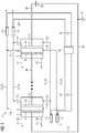
- Figure 1 shows an electrolysis system 1 with two electrolysis cells 2.
- two electrolysis cells 2 typically, significantly more than two electrolysis cells 2, in particular 50 to 100 electrolysis cells 2, are arranged in an electrolysis stack and thus in an electrolysis system 1. This is done in Figure 1 indicated by dots. For the sake of clarity, however, only two electrolysis cells 2 are shown in the figure.
- An electrolytic cell 2 comprises a separating membrane 14 which divides the electrolytic cell 2 into an anode compartment 3 and a cathode compartment.
- This separating membrane 14 can also be designed as a diaphragm.
- a cathode 6, in this example a gas diffusion electrode, is arranged in the cathode compartment.
- the cathode 6 divides the cathode compartment into a first cathode compartment 4 and a second cathode compartment 5.
- An anode 7 is arranged in the anode compartment 3. Appropriately, both the cathode 6 and the anode 7 are electrically connected.
- a gas comprising essentially carbon dioxide 10 is fed into the second cathode compartment 5. This is converted to valuable substances, in particular to carbon monoxide, at the cathode 6.
- the gas comprising carbon monoxide 11 leaves the second cathode compartment 5.
- a liquid catholyte 12 is fed into the first cathode compartment 4.
- the catholyte 12 is fed into the electrolytic cells 2 in parallel from a main feed line 50 of an electrolyte distributor. From this main feed line 50, feed lines 51 lead into the first cathode compartment 4 of the respective electrolysis cell 2.
- a liquid anolyte 13 is fed into the anode compartment 3.
- a feed line leads from the main feed line 50 to the individual electrolysis cells 2.
- the catholyte in turn leaves the electrolysis cell 2 via a discharge line 52.
- the discharge line 52 leads into a main discharge line 53.
- the discharge lines 52 from the first cathode compartment 4 of the electrolysis cells 2 are connected in parallel to this main discharge line 53.
- the anolyte also leaves the anode compartment 3 via a discharge line 52 and is led to a main discharge line 53.
- the leads 52 are in turn connected in parallel to this main lead 53.
- control electrodes made of silver are used on a negative potential. They are then inserted into the electrolyte supply lines and leads on the negative stack side.
- the polarity of the control electrodes can generally be selected independently of the polarity of the respective stack end. It is also possible to place the electrolyte-side stack connection in the middle of the stack. Then the interfaces of the electrolysis system to the environment are distributed over the stack surface.
- a first conductivity measuring device 15 is arranged in each of the main discharge lines 53.
- Second conductivity measuring devices 16 are arranged in each of the main supply lines 50.
- the first and second conductivity measuring devices 15, 16 are connected to an evaluation device 60 via data transmission lines 61.
- the first and the second conductivity measuring device 15, 16 measure the conductivity in the electrolyte and generate a measurement signal.
- the measurement signal is transmitted to an evaluation device 60 via the data transmission line 61.
- the Evaluation device evaluates the ratio of the conductivity measured at the first conductivity measuring device 15 in the catholyte after the electrolytic cell 2 to the conductivity measured at the second conductivity measuring device 16 in the catholyte upstream of the electrolytic cell. As soon as the ratio becomes smaller due to the reduced conductivity of the gas bubbles of a gas breakthrough through the gas diffusion electrode 6, the evaluation device outputs the information that a breakthrough point of the gas diffusion electrode 6 has been exceeded.
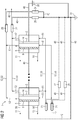
- Figure 2 shows a second example of an electrolysis system with two electrolysis cells and control electrodes with measuring resistors.
- the structure of the electrolysis cells corresponds to the structure of the electrolysis cells of the first example from FIG Figure 1 .
- control electrodes are arranged as first and second conductivity measuring devices in the main leads 50 and the main leads 53. These control electrodes are intended to keep corrosive stray currents in the aqueous electrolyte, that is to say anolyte 13 and catholyte 12, away from the surroundings of the electrolyte stack.
- the cells are typically connected electrically in series to form a stack, in particular a bipolar stack. The stray currents that occur are diverted from the electrolyte lines via the control electrodes and thus do not reach the system parts connected to the electrolysis cell via the electrolytes.
- control electrodes are designed as metallic pipe sections. These are only electronically connected to the negative end of the stack via the measuring resistors.
- the electrolytes can be conducted through these metallic pipe sections.
- the metallic pipe sections in particular have the circumference of the pipeline in which they are attached. They are connected to plastic pipes with the help of screw connections.
- the control electrodes are advantageous such an easy to manufacture geometry. Furthermore, there is an electronic connection to the negative end of the stack or the cathode only via the measuring resistors.
- the electrolysis system 1 comprises four control electrodes.
- a first control electrode 20 is arranged in the main discharge line 53 of the catholyte 12.
- a second control electrode 21 is arranged in the main supply line 50 of the catholyte 12.
- a third control electrode 22 is arranged in the main discharge line 53 of the anolyte 13.
- a fourth control electrode 23 is arranged in the main supply line 50 of the anolyte 13.
- the control electrodes are set to a defined potential, in this example the potential of the negative end of the stack, which also forms the grounding point.
- a measuring resistor 24, 25, 26, 27, English shunt, is arranged between the control electrodes 20, 21, 22, 23 and the grounding point 31. Each of these measuring resistors is used to measure a voltage drop, which in turn can be used to determine the stray currents flowing off via the measuring resistor (shunt).
- the diameter and length of the pipelines are to be selected depending on the resistances of the pipeline R R , the control electrode R M and the measuring resistor R M.
- Typical main distribution voltages are, depending on the design of the cell stack, in the range from 10 V to 100 V, from which R R / (R E + R M )> 10 follows. Ground currents in the range from 1 A to 10 A can be tolerated. A measuring resistor R M of 10 mQ is sufficient to generate easily measurable signals> 10 mV for the conductivity measurement, which on the other hand are so small that they do not negatively affect the quality of the grounding of the electrolyte. Technically sensible pipe lengths are therefore in a range from 0.5 m to 3 m. Larger electrical losses (> 0.1% of the nominal load) due to Joule heat release and gas development on the control electrode due to the earth currents are then excluded.
- control electrodes are not arranged in the immediate vicinity of the electrolysis cells 2, but at a distance of at least 10 cm, particularly preferably from 50 cm to 2 m, from the electrolysis cell 2.
- the line filled with electrolyte acts as an electrical resistor, which prevents excessive stray current.
- the voltage source is connected to the control electrodes in such a way that the negative pole of the voltage source is grounded. All control electrodes 20 to 23 thus act cathodically. A larger selection of material is advantageously available for the control electrodes. Reduction-stable metals, in particular silver in this example, are particularly preferably used.
- Figure 3 shows an electrical equivalent circuit diagram of a section of the electrolysis system 1 based on a derivative 52 of an anolyte.
- the electrolysis stack 33 comprises several electrolysis cells 2 with a cell voltage U Z. These are electrically connected in series.
- the electrolysis stack 33 is grounded on the negative side. This avoids an expensive bipolar power supply.
- the electrical equivalent circuit diagram of the anolyte supply line looks accordingly, that of the two catholyte leading lines 51, 52 differs from this in that the line resistance R S at the positive The end is omitted and instead is added at the negative end.
- the connection between the main discharge line 53 of the electrolyte stack 3 and the electrolyte conditioning system 17 has the stack connection resistance R P.
- the current resulting from the stray currents would flow via this resistor to the first electronically conductive and grounded surface of the electrolyte conditioning system 17, which is in contact with the electrolyte in the lines.
- a grounded control electrode 22 is attached before entry into the electrolyte conditioning system 17, which protects the following components.
- the control electrode 22 is connected to a third measuring resistor 26. A voltage drop 102 is measured here.
- Figure 4 shows the course of the voltage drop over time at the first control electrode 20 measured with the first measuring resistor 24.
- Time 100 is plotted on the x-axis.
- the differential pressure 101 over the gas diffusion electrode is plotted on the left y-axis.
- the voltage drop 102, which was measured at the first measuring resistor 24, is plotted on the right y-axis.
- the differential pressure is increased over time.
- the voltage drop across the first measuring resistor of 0.1 Ohm remains almost constant at the beginning. From the differential pressure at which gas bubbles break through the gas diffusion electrode, the voltage drop begins to decrease.
- a first differential pressure 106 can be read off the pressure drop curve, at which a breakdown point occurs across the gas diffusion electrode in the electrolysis system 1.
- the falling voltage drop across the first measuring resistor 24 indicates a lower leakage current. This lower stray current is based on an increased proportion of gas in the catholyte. Parameters such as the current strength of the electrolysis and volume flow rates of the media are kept constant in this example.
- the voltage drop which is present before the increase in the differential pressure across the gas diffusion electrode at the beginning is used as a reference value 104.
- a first voltage drop 105 is recognized when the voltage drop is below the reference value.
- the voltage drop that is measured across the second measuring resistor 25 can be used as a reference value. As soon as the value of the voltage drop across the first measuring resistor 24 deviates from the reference voltage drop, a gas breakdown through the gas diffusion electrode can be concluded. To determine a pressure difference at which the breakthrough takes place, the first voltage drop 105 can be used to infer the first pressure difference 106.
- the evaluation can in particular take place in an evaluation device with the aid of a computer.
- FIG. 10 shows a second example of a voltage drop which was measured across the first measuring resistor 24.
- Time 100 is again plotted on the x-axis.
- the gas breakthrough point was reached more quickly.
- the initially constant voltage drop 104 drops after a certain time. From this first voltage drop 105, it is then possible in turn to infer the presence of a gas breakdown through the gas diffusion electrode.
- the first differential pressure of the breakthrough point 106 can be inferred.
Landscapes
- Chemical & Material Sciences (AREA)
- Engineering & Computer Science (AREA)
- Chemical Kinetics & Catalysis (AREA)
- Electrochemistry (AREA)
- Materials Engineering (AREA)
- Metallurgy (AREA)
- Organic Chemistry (AREA)
- Inorganic Chemistry (AREA)
- Automation & Control Theory (AREA)
- Electrolytic Production Of Non-Metals, Compounds, Apparatuses Therefor (AREA)
Abstract
Die Erfindung betrifft ein Elektrolysesystem und ein Verfahren zum Speichern elektrischer Energie mittels des Elektrolysesystems. Es erfolgt zunächst das Bereitstellen eines Elektrolysesystems mit wenigstens einer Elektrolysezelle, wobei die Elektrolysezelle einen Kathodenraum aufweist, wobei in dem Kathodenraum eine Kathode angeordnet ist und die Kathode als eine Gasdiffusionselektrode ausgestaltet ist. Die Elektrolysezelle umfasst für jeden Elektrolyt eine Zuleitung und eine Ableitung. Das Elektrolysesystem umfasst auch wenigstens eine erste Leitfähigkeitsmessvorrichtung, die in einer der Ableitungen angebracht ist. Es wird eine erste Leitfähigkeit oder eine von der Leitfähigkeit abhängige Größe mit der ersten Leitfähigkeitsmessvorrichtung gemessen. Anschließend wird ein Gasdurchbruchspunkt durch die Gasdiffusionselektrode mittels Auswertens der ersten Leitfähigkeit oder eine von der Leitfähigkeit abhängige Größe in Relation zu einem Referenzwert in einer Auswertevorrichtung bestimmt.The invention relates to an electrolysis system and a method for storing electrical energy by means of the electrolysis system. An electrolysis system with at least one electrolysis cell is first provided, the electrolysis cell having a cathode space, a cathode being arranged in the cathode space and the cathode being designed as a gas diffusion electrode. The electrolytic cell comprises a supply line and a discharge line for each electrolyte. The electrolysis system also includes at least one first conductivity measuring device mounted in one of the downcomers. A first conductivity or a quantity dependent on the conductivity is measured with the first conductivity measuring device. A gas breakthrough point through the gas diffusion electrode is then determined by evaluating the first conductivity or a variable dependent on the conductivity in relation to a reference value in an evaluation device.
Description
Die Erfindung betrifft ein Elektrolysesystem und ein Verfahren zum Speichern elektrischer Energie mittels des Elektrolysesystems.The invention relates to an electrolysis system and a method for storing electrical energy by means of the electrolysis system.
Die Nachfrage nach Strom schwankt im tageszeitlichen Verlauf stark. Auch die Stromerzeugung schwankt mit zunehmendem Anteil an Strom aus erneuerbaren Energien während des Tagesverlaufs. Um ein Überangebot an Strom in Zeiten mit viel Sonne und starkem Wind bei niedriger Nachfrage nach Strom ausgleichen zu können, benötigt man regelbare Kraftwerke oder Speicher, um diese Energie zu speichern.The demand for electricity fluctuates strongly over the course of the day. Electricity generation also fluctuates over the course of the day as the share of electricity from renewable sources increases. In order to be able to compensate for an oversupply of electricity in times with a lot of sun and strong wind when there is low demand for electricity, controllable power plants or storage facilities are required to store this energy.
Eine der derzeitig angedachten Lösungen ist das Umwandeln von elektrischer Energie in Wertprodukte, die insbesondere als Plattformchemikalien, insbesondere Ethen, Methan, Ethan, oder Synthesegas, welches Kohlenstoffmonoxid und Wasserstoff umfasst, dienen können. Eine mögliche Technik zur Umwandlung der elektrischen Energie in Wertprodukte stellt die Elektrolyse dar.One of the solutions currently being considered is the conversion of electrical energy into products of value that can serve in particular as platform chemicals, in particular ethene, methane, ethane, or synthesis gas, which includes carbon monoxide and hydrogen. Electrolysis is a possible technique for converting electrical energy into valuable products.
Die Elektrolyse von Wasser zu Wasserstoff und Sauerstoff stellt eine im Stand der Technik bekannte Methode dar. Aber auch die Elektrolyse von Kohlenstoffdioxid zu Wertstoffen, insbesondere zu Kohlenstoffmonoxid wird seit einigen Jahren erforscht und es gibt Bemühungen, ein elektrochemisches System zu entwickeln, das eine Kohlenstoffdioxidmenge entsprechend des wirtschaftlichen Interesses reduzieren kann. Aktuell werden ca. 80 % des weltweiten Energiebedarfs durch die Verbrennung von fossilen Brennstoffen gedeckt, deren Verbrennungsprozesse eine weltweite Emission von etwa 34000 Millionen Tonnen Kohlenstoffdioxid in die Atmosphäre pro Jahr verursacht. Kohlenstoffdioxid gehört zu den sogenannten Treibhausgasen, deren negative Auswirkungen auf die Atmosphäre und das Klima diskutiert werden. Eine Verwertung dieses Kohlenstoffdioxids ist daher wünschenswert.The electrolysis of water to hydrogen and oxygen is a method known in the art. However, the electrolysis of carbon dioxide to form valuable substances, in particular to carbon monoxide, has been researched for several years and efforts are being made to develop an electrochemical system that can produce a corresponding amount of carbon dioxide of economic interest. Currently, around 80% of the world's energy needs are covered by burning fossil fuels, the combustion processes of which cause global emissions of around 34,000 million tons of carbon dioxide into the atmosphere every year. Carbon dioxide is one of the so-called greenhouse gases, their negative effects on the atmosphere and the climate will be discussed. Utilization of this carbon dioxide is therefore desirable.
Ein mögliches Zelldesign eines Kohlenstoffdioxid Elektrolyseurs umfasst einen Anodenraum und einen Kathodenraum. Im Kathodenraum ist eine Gasdiffusionselektrode als Kathode angeordnet. Eine Gasdiffusionselektrode ist eine poröse Struktur, die eine Gasphase, welche typischerweise das Edukt Kohlenstoffdioxid umfasst, und eine flüssige Phase voneinander trennt. Die flüssige Phase besteht typischerweise aus einer wässrigen Salzlösung, auch Elektrolyt genannt. Um diesen Typ des Kohlenstoffdioxid-Elektrolyseurs effizient zu betreiben, sollte über der Gasdiffusionselektrode ein definierter Differenzdruck eingestellt werden. Dieser Differenzdruck sollte so gewählt werden, dass die Poren der Gasdiffusionselektrode im Wesentlichen mit Gasphase gefüllt sind. Dieser Betriebspunktes der Gasdiffusionselektrode liegt nahe am Durchbruchspunkt, englisch "Bubble Point". Dieser Durchbruchspunkt bezeichnet den Betriebspunkt, bei dem das Gas beginnt durch die poröse Struktur der Gasdiffusionselektrode hindurch bis in den Elektrolytraum gedrückt zu werden. Dort, wo das Gas auf diese Weise den leitfähigen Elektrolyten verdrängt, sinkt die über den Elektrolytspalt gemittelte Leitfähigkeit, so dass bei gleichem Strom eine höhere Betriebsspannung erforderlich ist: Die Effizienz des Elektrolyse-Prozesses sinkt. Nachteilig kann es zur Schädigung der Gasdiffusionselektrode und anderer Zellkomponenten kommen, da insbesondere der Strom in blasenfreie Elektrolytbereiche ausweicht und dort dann höhere Stromdichten auftreten, die die Alterungsprozesse nachteilig beschleunigen. Das Überschreiten des Durchbruchspunktes sollte somit vermieden werden.One possible cell design of a carbon dioxide electrolyser comprises an anode compartment and a cathode compartment. A gas diffusion electrode is arranged as a cathode in the cathode space. A gas diffusion electrode is a porous structure that separates a gas phase, which typically comprises the starting material carbon dioxide, and a liquid phase from one another. The liquid phase typically consists of an aqueous salt solution, also called an electrolyte. In order to operate this type of carbon dioxide electrolyzer efficiently, a defined differential pressure should be set across the gas diffusion electrode. This differential pressure should be chosen so that the pores of the gas diffusion electrode are essentially filled with the gas phase. This operating point of the gas diffusion electrode is close to the breakthrough point, English "bubble point". This breakthrough point denotes the operating point at which the gas begins to be pressed through the porous structure of the gas diffusion electrode into the electrolyte space. Where the gas displaces the conductive electrolyte in this way, the conductivity averaged over the electrolyte gap decreases, so that a higher operating voltage is required for the same current: The efficiency of the electrolysis process decreases. Disadvantageously, the gas diffusion electrode and other cell components can be damaged, since in particular the current escapes into bubble-free electrolyte areas and higher current densities then occur there, which disadvantageously accelerate the aging process. Exceeding the break-through point should therefore be avoided.
Es ist vorteilhaft, den Kohlenstoffdioxid Elektrolyseur möglichst nahe am Durchbruchspunkt zu betreiben. Ein Überschreiten des Durchbruchspunktes muss aber vermieden werden. Der optimale Differenzdruck über der Gasdiffusionselektrode hängt dabei von einigen Faktoren ab. Durch zeitliche Effekte, insbesondere durch ein Quellen der Gasdiffusionselektrode, kann sich der Durchbruchspunkt mit der Zeit ändern. Somit ändert sich nachteilig auch der optimale Differenzdruck über der Gasdiffusionselektrode. Außerdem wird der Differenzdruck über der Gasdiffusionselektrode von hydrostatischen und dynamischen Effekten beeinflusst, wodurch lokal unterschiedliche Differenzdrücke an der aktiven Fläche einer Gasdiffusionselektrode vorliegen können. Der Differenzdruck zwischen Gas und Elektrolytraum, der an einer bestimmten Stelle in der Zelle oder in den entsprechenden Zuleitungen gemessen wird, ist erkennt den Durchbruchspunktes somit nachteilig nur sehr ungenau.It is advantageous to operate the carbon dioxide electrolyzer as close as possible to the breakthrough point. Exceeding the break-through point must be avoided. The optimum differential pressure across the gas diffusion electrode depends on a number of factors. By temporal effects, in particular by swelling of the gas diffusion electrode, the breakthrough point will change over time. The optimum differential pressure across the gas diffusion electrode therefore also changes disadvantageously. In addition, the differential pressure across the gas diffusion electrode is influenced by hydrostatic and dynamic effects, which means that locally different differential pressures can exist on the active surface of a gas diffusion electrode. The differential pressure between the gas and the electrolyte space, which is measured at a certain point in the cell or in the corresponding supply lines, is therefore disadvantageously only very imprecisely recognizing the breakout point.
Es ist daher Aufgabe der vorliegenden Erfindung einen Kohlenstoffdioxid-Elektrolyseur und ein Verfahren zum Betreiben eines Kohlenstoffdioxid-Elektrolyseurs anzugeben, welches eine zuverlässige Erkennung des Durchbuchpunktes erreicht und somit ein möglichst effizientes Umsetzen des Kohlenstoffdioxid-Elektrolyseurs am Durchbruchspunkt ermöglicht.It is therefore the object of the present invention to provide a carbon dioxide electrolyzer and a method for operating a carbon dioxide electrolyzer which achieves reliable detection of the through-hole point and thus enables the carbon dioxide electrolyzer to be implemented as efficiently as possible at the breakthrough point.
Die Aufgabe wird mit einem Elektrolysesystem gemäß Anspruch 1 und einem Verfahren zum Betreiben eines Elektrolysesystems gemäß Anspruch 10 gelöst.The object is achieved with an electrolysis system according to claim 1 and a method for operating an electrolysis system according to
Das erfindungsgemäße Elektrolysesystem zur Kohlenstoffdioxid-Elektrolyse umfasst wenigstens eine Elektrolysezelle, wobei eine Elektrolysezelle einen Kathodenraum umfasst. In dem Kathodenraum ist eine Kathode angeordnet. Die Kathode ist als eine Gasdiffusionselektrode ausgestaltet. Die Elektrolysezelle umfasst wenigstens eine erste Zuleitung und eine erste Ableitung zum Führen eines Katholyten. Das Elektrolysesystem umfasst wenigstens eine erste Leitfähigkeitsmessvorrichtung, welche in der ersten Ableitung angeordnet ist. Die Leitfähigkeitsmessvorrichtung ist zum Messen der Leitfähigkeit oder einer von der Leitfähigkeit abhängigen Größe und zum Erzeugen eines Messsignals geeignet. Das Elektrolysesystem umfasst weiterhin eine Auswertevorrichtung zum Bestimmen eines Durchbruchpunktes durch die Gasdiffusionselektrode basierend auf dem ersten Messsignal der ersten Leitfähigkeitsmessvorrichtung in Relation zu einem Referenzwert.The electrolysis system according to the invention for carbon dioxide electrolysis comprises at least one electrolysis cell, one electrolysis cell including a cathode compartment. A cathode is arranged in the cathode compartment. The cathode is designed as a gas diffusion electrode. The electrolytic cell comprises at least a first supply line and a first discharge line for guiding a catholyte. The electrolysis system comprises at least one first conductivity measuring device, which is arranged in the first derivative. The conductivity measuring device is suitable for measuring the conductivity or a quantity dependent on the conductivity and for generating a measurement signal. The electrolysis system further comprises an evaluation device for determining a breakdown point through the gas diffusion electrode based on the first measurement signal of the first conductivity measuring device in relation to a reference value.
Das erfindungsgemäße Verfahren zum Betreiben eines Elektrolysesystems zur Kohlenstoffdioxid-Elektrolyse umfasst zunächst das Bereitstellen eines Elektrolysesystems. Das Elektrolysesystem umfasst wenigstens eine Elektrolysezelle. Eine Elektrolysezelle umfasst einen Kathodenraum. In dem Kathodenraum ist eine Kathode angeordnet. Die Kathode ist als eine Gasdiffusionselektrode ausgestaltet. Die Kathode umfasst wenigstens eine erste Zuleitung und eine erste Ableitung zum Führen eines Katholyten. Das Elektrolysesystem umfasst wenigstens eine erste Leitfähigkeitsmessvorrichtung, welche in der ersten Ableitung angeordnet ist, zum Messen der Leitfähigkeit oder einer von der Leitfähigkeit abhängigen Größe und zum Erzeugen eines Messsignals. Das Elektrolysesystem umfasst auch eine Auswertevorrichtung zum Bestimmen eines Gasdurchbruchpunktes durch die Gasdiffusionselektrode basierend auf dem Messsignal der ersten Leitfähigkeitsmessvorrichtung in Relation zu einem Referenzwert. Die Leitfähigkeit oder einer von der Leitfähigkeit abhängigen proportionalen Größe wird mittels der ersten Leitfähigkeitsmessvorrichtung gemessen und ein erstes Messsignal wird erzeugt. Ein Gasdurchbruchspunkt durch die Gasdiffusionselektrode wird basierend auf dem Messsignal der Leitfähigkeitsmessvorrichtung in Relation zu einem Referenzwert in bestimmt.The method according to the invention for operating an electrolysis system for carbon dioxide electrolysis initially comprises the provision of an electrolysis system. The electrolysis system comprises at least one electrolysis cell. An electrolysis cell includes a cathode compartment. A cathode is arranged in the cathode compartment. The cathode is designed as a gas diffusion electrode. The cathode comprises at least a first supply line and a first discharge line for guiding a catholyte. The electrolysis system comprises at least one first conductivity measuring device, which is arranged in the first derivation, for measuring the conductivity or a quantity dependent on the conductivity and for generating a measurement signal. The electrolysis system also includes an evaluation device for determining a gas breakthrough point through the gas diffusion electrode based on the measurement signal of the first conductivity measurement device in relation to a reference value. The conductivity or a proportional variable dependent on the conductivity is measured by means of the first conductivity measuring device and a first measurement signal is generated. A gas breakthrough point through the gas diffusion electrode is determined based on the measurement signal of the conductivity measuring device in relation to a reference value in.
Es hat sich gezeigt, dass sich die Leitfähigkeit in der ersten Ableitung der Elektrolysezelle, also der Katholytableitung, in Abhängigkeit des Betriebspunktes, insbesondere des Durchbruchspunkt der Gasdiffusionselektrode, verändert. Wird der Durchbruchspunkt, engl.: "Bubble Point", überschritten, so gelangen Gasbläschen in den Elektrolyten. Der Elektrolyt mit den Gasbläschen verlässt den Kohlenstoffdioxid-Elektrolyseur und strömt durch die Leitfähigkeitsmessvorrichtung. Aufgrund der Gasbläschen im Elektrolyten wird die Leitfähigkeit des Elektrolyts herabgesetzt. Es ist somit vorteilhaft möglich, den Durchbruchspunkt der Gasdiffusionselektrode zuverlässig anhand eines Abfalls der Leitfähigkeit zu bestimmen.It has been shown that the conductivity in the first derivative of the electrolysis cell, that is to say the catholyte discharge, changes depending on the operating point, in particular the breakdown point of the gas diffusion electrode. If the breakthrough point, or "bubble point", is exceeded, gas bubbles enter the electrolyte. The electrolyte with the gas bubbles leaves the carbon dioxide electrolyser and flows through the conductivity measuring device. Due to the gas bubbles in the electrolyte, the conductivity of the electrolyte is reduced. It is thus advantageously possible to use the breakdown point of the gas diffusion electrode can be reliably determined on the basis of a drop in conductivity.
In einer vorteilhaften Ausgestaltung und Weiterbildung der Erfindung wird als das Messsignal eine Leitfähigkeit oder ein Spannungsabfall verwendet. Vorteilhaft kann sowohl über eine direkte Leitfähigkeitsmessung in dem Elektrolyten, insbesondere in dem Katholyten, als auch über eine von der Leitfähigkeit abhängige Größe, nämlich einem Spannungsabfall in dem Elektrolyten, der Durchbruchspunkt über die Gasdiffusionselektrode zuverlässig bestimmt werden.In an advantageous embodiment and development of the invention, a conductivity or a voltage drop is used as the measurement signal. The breakdown point via the gas diffusion electrode can advantageously be reliably determined both via a direct conductivity measurement in the electrolyte, in particular in the catholyte, and via a quantity dependent on the conductivity, namely a voltage drop in the electrolyte.
In einer weiteren vorteilhaften Ausgestaltung und Weiterbildung der Erfindung wird der Referenzwert zeitlich vor dem ersten Messsignal mit der ersten Leitfähigkeitsmessvorrichtung gemessen. Vorteilhaft wird so nur ein Messaufbau in einer Elektrolysezelle benötigt, um den Durchbruchspunkt zu bestimmen. In der Auswertevorrichtung werden die Messsignale insbesondere auf einem Datenträger gespeichert und der Durchbruchspunkt wird anhand mehrere zeitlich versetzter Messsignale ausgewertet. Zweckmäßigerweise erfolgt die zeitlich frühere Messung vor einem Durchbruch durch die Gasdiffusionselektrode, also bevor eine signifikante Gasmenge in der Ableitung in dem Elektrolyten vorliegt. Es ist insbesondere sinnvoll die Leitfähigkeit oder eine von der Leitfähigkeit abhängige Größe, insbesondere einen Spannungsabfall, an der ersten Leitfähigkeitsmessvorrichtung bereits ab Inbetriebnahme der Elektrolysezelle zu messen. Wird die Leitfähigkeit geringer, so kann auf einen Durchbruchspunkt durch die Gasdiffusionselektrode geschlossen werden.In a further advantageous embodiment and development of the invention, the reference value is measured with the first conductivity measuring device before the first measurement signal. Advantageously, only one measurement setup in an electrolysis cell is required to determine the breakout point. In the evaluation device, the measurement signals are stored, in particular on a data carrier, and the break-through point is evaluated on the basis of several time-shifted measurement signals. The earlier measurement is expediently carried out before a breakthrough through the gas diffusion electrode, that is to say before a significant amount of gas is present in the discharge line in the electrolyte. It is particularly useful to measure the conductivity or a variable that is dependent on the conductivity, in particular a voltage drop, at the first conductivity measuring device as soon as the electrolysis cell is started up. If the conductivity becomes lower, a breakdown point through the gas diffusion electrode can be deduced.
Die Auswertung und somit Bestimmung des Durchbruchspunktes kann insbesondere beruhend auf folgenden Zusammenhängen erfolgen:
Der Elektrolytvolumenstrom, der in eine Elektrolysezelle im Wesentlichen frei von Gasblasen eingeführt wird, insbesondere der Katholyteingangsstrom, beträgt JL1. Ein flüssiger Elektrolytvolumenstrom, der die Elektrolysezelle, insbesondere den Kathodenraum, verlässt, beträgt JL2, wenn die Gasdiffusionselektrode unterhalb des Bubble-Points betrieben wird. Die Leitfähigkeit des flüssigen Katholyten in der Zuleitung oder Hauptzuleitung beträgt σL1. Die Leitfähigkeit des flüssigen Elektrolyten in der Ableitung oder Hauptableitung beträgt σL2. Der flüssige Katholyteingangsstrom und der flüssige Katholytausgangsstrom sind im Wesentlichen gleich. Es gibt lediglich geringe Abweichungen durch eine geringfügige Änderung der Elektrolytzusammensetzung durch die Zellreaktion und eine geringe Temperaturerhöhung. Daher können folgende Annahmen getroffen werden: ![]()
The electrolyte volume flow that is introduced into an electrolysis cell essentially free of gas bubbles, in particular the catholyte input flow, is J L1 . A liquid electrolyte volume flow, which leaves the electrolysis cell, in particular the cathode compartment, is J L2 if the gas diffusion electrode is operated below the bubble point. The conductivity of the liquid catholyte in the supply line or main supply line is σ L1 . The conductivity of the liquid electrolyte in the discharge or main discharge is σ L2 . The liquid catholyte input stream and the liquid catholyte output stream are essentially the same. There are only minor deviations due to a slight change in the electrolyte composition due to the cell reaction and a slight increase in temperature. Therefore, the following assumptions can be made:![]()
Die Katholytableitung aus der Elektrolysezelle und die Hauptableitung des Elektrolytverteilers enthält bei einem Betriebspunkt unterhalb des Gas-Durchbruchpunktes durch die Gasdiffusionselektrode nur wenige Blasen. Die wenigen Blasen entstehen durch eine Freisetzung geringer Reaktionsmengen auf der Katholytseite der Gasdiffusionselektrode. Der Gasvolumenstrom, der im Katholyt in Form einer Zweiphasenströmung mitgeführt wird, beträgt JG0. Gleichung 2 beschreibt näherungsweise die Leitfähigkeit σ2 in einem Volumenelement nach der Elektrolysezelle unter Berücksichtigung dieses Gasanteils. Dabei entspricht σ2 der Leitfähigkeit vor einem Gasdurchbruch durch die Gasdiffusionselektrode. Aufgrund der Annahme aus Gleichung 1, kann die Gesamt-Leitfähigkeit σ2 auch mittels der Leitfähigkeit des Elektrolyten vor der Elektrolysezelle σL1 und dem Elektrolytvolumenstrom JL1 näherungsweise beschrieben werden. ![]()
![]()
Bei Erreichen des Durchbruchpunktes tritt ein mit dem Differenzdruck über der Gasdiffusionselektrode rasch ansteigender Gasstrom JGE vom Eduktgasraum durch die Gasdiffusionselektrode in den Katholyt über und führt dort entsprechend zu einem starken Anstieg des Gasvolumenstroms hin zu (JG0 + JGE). Die Leitfähigkeit σ2' entspricht der Leitfähigkeit nach einem Gasdurchbruch durch die Gasdiffusionselektrode. Die Leitfähigkeit sinkt entsprechend der Gleichung 3. ![]()
![]()
Da sich bei einem Gasdurchbruch rasch JGE >> JG0 einstellt, gilt folgende Näherung: ![]()
![]()
Der Gasdurchbruch durch die Gasdiffusionselektrode ist über eine Verminderung der Leitfähigkeit oder über ein Verringern eines Spannungsabfalls, gemessen in einem ersten Messwiderstand in der ersten Ableitung, also durch ein indirektes Messen der Leitfähigkeit in der Katholytableitung um den in Gleichung 5 angegebenen Faktor messbar. Dieser Wert der Leitfähigkeit σ2' kann zeitlich nacheinander mehrmals aufgenommen werden. Ein Absinken des Wertes deutet auf einen Gasdurchbruch durch die Gasdiffusionselektrode hin. ![]()
![]()
Vorteilhaft wird in diesem Fall nur eine Messvorrichtung eingesetzt, die mehrmals zeitlich hintereinander Messwerte aufnimmt und ein Messignal ausgibt.In this case, only one measuring device is advantageously used which records measured values several times in succession and outputs a measuring signal.
In einer weiteren vorteilhaften Ausgestaltung und Weiterbildung der Erfindung wird der Referenzwert mittels einer zweiten Leitfähigkeitsmessvorrichtung, welche in einer Zuleitung der Elektrolysezelle angeordnet ist, gemessen. In anderen Worten umfasst das Elektrolysesystem nun zwei Leitfähigkeitsmessvorrichtungen. Die erste Leitfähigkeitsmessvorrichtung misst die Leitfähigkeit oder eine von der Leitfähigkeit abhängige Größe nach der Elektrolysezelle in einer ersten Ableitung, insbesondere in einer Katholytableitung. Die zweite Leitfähigkeitsmessvorrichtung misst die Leitfähigkeit oder eine von der Leitfähigkeit abhängende Größe vor der Elektrolysezelle, also in einer Zuleitung zur Elektrolysezelle. Der Messwert der zweiten Leitfähigkeitsmessvorrichtung stellt dann den Referenzwert für eine Auswertung des Durchbruchspunktes dar.In a further advantageous embodiment and development of the invention, the reference value is measured by means of a second conductivity measuring device which is arranged in a feed line of the electrolytic cell. In other words, the electrolysis system now comprises two conductivity measuring devices. The first conductivity measuring device measures the conductivity or one that is dependent on the conductivity Size after the electrolysis cell in a first discharge, in particular in a catholyte discharge. The second conductivity measuring device measures the conductivity or a quantity dependent on the conductivity upstream of the electrolytic cell, that is to say in a feed line to the electrolytic cell. The measured value of the second conductivity measuring device then represents the reference value for an evaluation of the breakthrough point.
Vorteilhaft kann mit der in Gleichung 4 beschriebenen Näherung die Leitfähigkeit in der Katholytableitung beschrieben werden. Mit dieser Näherung kann ein Referenzwert ohne eine zeitlich frühere Messung bestimmt werden. Es wird als Referenzwert eine Leitfähigkeit oder ein Spannungsabfall an dem Elektrolytzulauf gemessen. Daraus kann auf die den Gasvolumenstrom JGE in der Ableitung der Elektrolysezelle geschlossen werden und somit der Durchbruchspunkt bestimmt werden. Vorteilhaft kann somit in Echtzeit der Betriebspunkt der Gasdiffusionselektrode bestimmt werden, da keine zeitlich vorherigen Messungen nötig sind.The conductivity in the catholyte discharge can advantageously be described with the approximation described in
In einer weiteren vorteilhaften Ausgestaltung und Weiterbildung der Erfindung umfasst das Elektrolysesystem eine Regelvorrichtung zum Regeln eines Differenzdruckes über der Gasdiffusionselektrode in Abhängigkeit des Messsignals der Leitfähigkeitsmessvorrichtung. In anderen Worten heißt das, das in dem Fall, dass das Auswerten ergibt, dass ein Gasdurchbruchspunkt überschritten ist, der Differenzdruck über der Gasdiffusionselektrode mittels der Regelvorrichtung vermindert wird. Das Regelsystem ermöglich somit vorteilhaft, die Elektrolysezelle möglichst nah am Gasdurchbruchspunkt zu betreiben und bei einem Gasdurchbruch die Druckdifferenz derart zu vermindern, dass der Betriebspunkt der Gasdiffusionselektrode unterhalb des Gasdurchbruchpunktes bleibt.In a further advantageous embodiment and development of the invention, the electrolysis system comprises a control device for controlling a differential pressure across the gas diffusion electrode as a function of the measurement signal from the conductivity measurement device. In other words, this means that in the event that the evaluation shows that a gas breakthrough point has been exceeded, the differential pressure across the gas diffusion electrode is reduced by means of the control device. The control system thus advantageously enables the electrolysis cell to be operated as close as possible to the gas breakthrough point and, in the event of a gas breakthrough, to reduce the pressure difference such that the operating point of the gas diffusion electrode remains below the gas breakthrough point.
In einer weiteren vorteilhaften Ausgestaltung und Weiterbildung der Erfindung weist die erste Leitfähigkeitsmessvorrichtung Leitfähigkeitssensoren oder Widerstandsmessstrecken in der ersten Ableitung und/oder in der ersten Zuleitung auf. Alternativ oder zusätzlich weist das Elektrolysesystem eine zweite Zuleitung in die Elektrolysezelle und eine zweite Ableitung aus der Elektrolysezelle zum Führen eines Anolyten auf. Eine zweite Leitfähigkeitsmessvorrichtung weist dann auch Leitfähigkeitssensoren oder Widerstandsmessstrecken in der zweiten Zuleitung und/oder der zweiten Ableitung auf. Vorteilhaft sind dies robuste Messeinheiten, welche wartungsarm sind und zuverlässig messen.In a further advantageous embodiment and development of the invention, the first conductivity measuring device has conductivity sensors or resistance measuring sections the first derivation and / or in the first supply line. Alternatively or additionally, the electrolysis system has a second supply line into the electrolysis cell and a second discharge line from the electrolysis cell for carrying an anolyte. A second conductivity measuring device then also has conductivity sensors or resistance measuring sections in the second supply line and / or the second discharge line. These are advantageously robust measuring units that require little maintenance and measure reliably.
In einer weiteren vorteilhaften Ausgestaltung und Weiterbildung der Erfindung umfasst die erste Leitfähigkeitsmessvorrichtung eine erste Steuerelektrode zur Aufnahme von Streuströmen und einen ersten Messwiderstand zum Messen eines ersten Spannungsabfalls. Die wenigstens eine erste Steuerelektrode ist in der ersten Ableitung angebracht und der erste Messwiderstand ist elektrisch mit der ersten Steuerelektrode verbunden. In anderen Worten ist der erste Messwiderstand in der elektrischen Leitung angebracht, durch die der Streustrom die Katholytableitung oder die Anolytableitung verlässt. Vorteilhaft kann mittels des ersten Messwiderstands ein Spannungsabfall gemessen werden, welcher abhängig von der Leitfähigkeit ist.In a further advantageous embodiment and development of the invention, the first conductivity measuring device comprises a first control electrode for receiving stray currents and a first measuring resistor for measuring a first voltage drop. The at least one first control electrode is attached in the first derivative and the first measuring resistor is electrically connected to the first control electrode. In other words, the first measuring resistor is fitted in the electrical line through which the stray current leaves the catholyte discharge or the anolyte discharge. The first measuring resistor can advantageously be used to measure a voltage drop which is dependent on the conductivity.
Steuerelektroden sind in Elektrolysesystemen, insbesondere mit wenigstens zwei Elektrolysezellen, die als Stack miteinander verbunden sind, zur Aufnahme von Streuströmen angeordnet. Die einzelnen Elektrolysezellen sind mit Zuleitungen und Ableitungen zur Versorgung mit Elektrolyt verbunden. Die einzelnen Zuleitungen sind, um die Rohrverbindungen effizient zu gestalten wiederum mit einer gemeinsamen Zuleitung, einer Hauptzuleitung, jeweils parallel verbunden. Die Ableitungen sind mit einer gemeinsamen Ableitung, einer Hauptableitung, jeweils parallel verbunden. Die erste und/oder zweite Leitfähigkeitsmessvorrichtung kann auch in dieser Hauptableitung oder Hauptzuleitung angeordnet sein. In anderen Worten ist Ableitung und Zuleitung jeweils ein Oberbegriff, der auch die hier verwendeten Begriffe Hauptableitung oder Hauptzuleitung umfasst.Control electrodes are arranged in electrolysis systems, in particular with at least two electrolysis cells, which are connected to one another as a stack, for receiving stray currents. The individual electrolysis cells are connected to supply lines and discharge lines for the supply of electrolyte. In order to make the pipe connections efficient, the individual feed lines are in turn connected in parallel to a common feed line, a main feed line. The leads are connected in parallel to a common lead, a main lead. The first and / or second conductivity measuring device can also be arranged in this main discharge line or main supply line. In other words, derivation and supply are each a generic term that also includes the Terms used here include main derivation or main supply line.
Durch das Ergänzen dieser bereits in einem Elektrolysesystem vorliegenden Steuerelektroden um einen ersten Messwiderstand, können diese Steuerelektroden zusätzlich zur Aufnahme von Streuströmen auch zur Analyse des Gasdurchbruchpunktes herangezogen werden. Es ist vorteilhafterweise nicht nötig, zusätzliche Sensoren in die Zuleitung und/oder Ableitung des Elektrolysesystems einzubringen.By adding a first measuring resistor to these control electrodes already present in an electrolysis system, these control electrodes can also be used to analyze the gas breakdown point in addition to recording stray currents. It is advantageously not necessary to introduce additional sensors in the supply line and / or discharge line of the electrolysis system.
In einer weiteren vorteilhaften Ausgestaltung und Weiterbildung der Erfindung umfasst das Elektrolysesystem wenigstens zwei Steuerelektroden, wobei die zweite Leitfähigkeitsmessvorrichtung eine zweite Steuerelektrode, die in der Zuleitung der Elektrolysezelle angeordnet ist, aufweist. Die zweite Steuerelektrode ist vorteilhaft elektrisch mit einem zweiten Messwiderstand zum Messen eines zweiten Spannungsabfalls an diesem verbunden. Die zweite Steuerelektrode ist in der Zuleitung zu der Elektrolysezelle, also in Strömungsrichtung vor der Elektrolysezelle, angeordnet. An dem zweiten Messwiderstand wird ein zweiter Spannungsabfall gemessen. Dieser zweite Spannungsabfall wird als Referenzwert eingesetzt. Da der zweite Messwiderstand in Strömungsrichtung vor der Elektrolysezelle angeordnet ist, kann davon ausgegangen werden, dass dieser Spannungsabfall dem Spannungsabfall entspricht, bei dem im Elektrolyt im Wesentlichen kein Gas umfassend Kohlenstoffdioxid vorliegt. Vorteilhaft kann somit der Betriebspunkt der Gasdiffusionselektrode in Echtzeit aufgenommen werden. Wird der Durchbruchspunkt überschritten ist somit vorteilhaft ein schnelles Anpassen der Druckdifferenz über der Gasdiffusionselektrode möglich.In a further advantageous embodiment and development of the invention, the electrolysis system comprises at least two control electrodes, the second conductivity measuring device having a second control electrode which is arranged in the feed line of the electrolysis cell. The second control electrode is advantageously electrically connected to a second measuring resistor for measuring a second voltage drop across it. The second control electrode is arranged in the feed line to the electrolytic cell, that is to say in front of the electrolytic cell in the direction of flow. A second voltage drop is measured at the second measuring resistor. This second voltage drop is used as a reference value. Since the second measuring resistor is arranged upstream of the electrolytic cell in the direction of flow, it can be assumed that this voltage drop corresponds to the voltage drop at which there is essentially no gas comprising carbon dioxide in the electrolyte. The operating point of the gas diffusion electrode can thus advantageously be recorded in real time. If the breakthrough point is exceeded, a quick adjustment of the pressure difference across the gas diffusion electrode is thus advantageously possible.
In einer weiteren vorteilhaften Ausgestaltung und Weiterbildung der Erfindung sind die erste und die zweite Steuerelektrode über den ersten und zweiten Messwiderstand auf ein selbes Potential gelegt. Das heißt in anderen Worten, dass zwischen der Steuerelektrode und dem Potentialpunkt der Messwiderstand angeordnet ist.In a further advantageous embodiment and development of the invention, the first and the second control electrode are connected to the same potential via the first and second measuring resistor. In other words, that means between the control electrode and the potential point of the measuring resistor is arranged.
In einer weiteren vorteilhaften Ausgestaltung und Weiterbildung der Erfindung sind die erste und die zweite Steuerelektrode über den jeweils ersten Messwiderstand oder den zweiten Messwiderstand geerdet. Das heißt in anderen Worten, dass zwischen der Steuerelektrode und dem Erdungspunkt der Messwiderstand angeordnet ist. Vorteilhaft verhindert dieser Aufbau eine Korrosion von Elektrolysesystemteilen, die mit dem Elektrolyten in Kontakt stehen, da die Elektroden den Elektrolyten erden.In a further advantageous embodiment and development of the invention, the first and the second control electrode are grounded via the respective first measuring resistor or the second measuring resistor. In other words, that means that the measuring resistor is arranged between the control electrode and the grounding point. This structure advantageously prevents corrosion of parts of the electrolysis system that are in contact with the electrolyte, since the electrodes ground the electrolyte.
In einer weiteren vorteilhaften Ausgestaltung und Weiterbildung der Erfindung ist die Kathode der Elektrolysezelle mit einem Minuspol einer Spannungsquelle elektrisch verbunden und der Minuspol ist geerdet. Somit wirken sämtliche Steuerelektroden kathodisch. Dies hat den Vorteil, dass eine Vielzahl an Materialen für die Steuerelektrode einsetzbar ist. Insbesondere können reduktionsstabile Metalle, insbesondere Silber, eingesetzt werden.In a further advantageous embodiment and development of the invention, the cathode of the electrolysis cell is electrically connected to a negative pole of a voltage source and the negative pole is grounded. All control electrodes thus act cathodically. This has the advantage that a large number of materials can be used for the control electrode. In particular, reduction-stable metals, in particular silver, can be used.
In einer weiteren vorteilhaften Ausgestaltung und Weiterbildung der Erfindung umfasst die Elektrolysezelle einen Anodenraum und den Kathodenraum. Der Anodenraum ist von dem Kathodenraum durch eine Membran getrennt. Als Membran wird hier sowohl ein Diaphragma als auch eine klassische Membran bezeichnet. Die Aufgabe dieser Membran ist es, Gase zu trennen und Ionen zu leiten, um einen elektrischen Strom aufzubringen. Vorteilhaft werden in dem Anodenraum und dem Kathodenraum getrennt voneinander unterschiedliche Produkte, insbesondere Gase, produziert. Diese können den Elektrolyseur dann auch getrennt verlassen, was vorteilhaft ein Auftrennen der Produkte überflüssig macht. Da Trennprozesse einen hohen Energiebedarf haben, wird vorteilhaft auch Energie gespart. Das macht den Elektrolyseur energieeffizient.In a further advantageous embodiment and development of the invention, the electrolysis cell comprises an anode compartment and the cathode compartment. The anode compartment is separated from the cathode compartment by a membrane. Both a diaphragm and a classic membrane are referred to here as a membrane. The job of this membrane is to separate gases and conduct ions to apply an electric current. Different products, in particular gases, are advantageously produced separately from one another in the anode compartment and the cathode compartment. These can then also leave the electrolyser separately, which advantageously makes separating the products superfluous. Since separation processes have a high energy requirement, energy is also advantageously saved. That makes the electrolyzer energy efficient.
In einer weiteren vorteilhaften Ausgestaltung und Weiterbildung der Erfindung ist die erste und/oder zweite Steuerelektrode längs entlang der Elektrolytleitung wenigstens 10 cm, besonders bevorzugt wenigstens 50 cm von der Elektrolysezelle entfernt angeordnet. Dies hat den Vorteil, dass größere elektrische Verluste durch hohe Erdungströme vermieden werden. Insbesondere wird der Anteil des elektrischen Widerstands des Elektrolyten größer in Relation zum gesamten gemessenen Widerstand, wobei sich der gesamte Widerstand im Wesentlichen aus dem Widerstand der Rohrleitung, dem Messwiderstand und dem elektrischen Widerstand zusammensetzt. Dadurch wird die Veränderung des Spannungsabfalls am Durchbruchspunkt größer, je weiter die Messstelle von der Elektrolysezelle entfernet ist. In anderen Worten wird die Messqualität vorteilhaft besser, wenn die Steuerelektrode wenigstens 10 cm, besonders bevorzugt wenigstens 50 cm von der Elektrolysezelle entfernt ist.In a further advantageous embodiment and development of the invention, the first and / or second control electrode is arranged along the electrolyte line at least 10 cm, particularly preferably at least 50 cm, from the electrolytic cell. This has the advantage that major electrical losses due to high grounding currents are avoided. In particular, the proportion of the electrical resistance of the electrolyte becomes greater in relation to the total measured resistance, the total resistance being essentially composed of the resistance of the pipeline, the measuring resistor and the electrical resistance. As a result, the change in the voltage drop at the breakdown point increases the further away the measuring point is from the electrolytic cell. In other words, the measurement quality is advantageously better if the control electrode is at least 10 cm, particularly preferably at least 50 cm, from the electrolytic cell.
In einer weiteren vorteilhaften Ausgestaltung und Weiterbildung der Erfindung sind die Leitfähigkeitsmesselektroden als Rohrabschnitte in der Zuleitung und/oder Ableitung der Elektrolysezelle ausgebildet. Die Rohrabschnitte weisen dabei insbesondere einen Zu- oder Ableitungsdurchmesser auf. Die Länge der Rohrabschnitte entspricht insbesondere höchstens der Länge von einigen Leitungsdurchmessern der Leitung, in der sie angeordnet sind. Eine Wandstärke der Rohrabschnitte kann dabei 0,1 mm bis einige mm betragen. Vorteilhaft sind bei diesen Wandstärken mechanische Stabilität und Standzeit auch im Fall eines schwachen korrosiven Angriffs gewährleistet.In a further advantageous embodiment and development of the invention, the conductivity measuring electrodes are designed as pipe sections in the feed line and / or discharge line of the electrolytic cell. The pipe sections have in particular an inlet or outlet diameter. In particular, the length of the pipe sections corresponds at most to the length of a few pipe diameters of the pipe in which they are arranged. A wall thickness of the pipe sections can be 0.1 mm to a few mm. With these wall thicknesses, mechanical stability and service life are advantageously guaranteed even in the event of a weak corrosive attack.
In einer weiteren vorteilhaften Ausgestaltung und Weiterbildung der Erfindung erfolgt das Auswerten derart, dass die Leitfähigkeitsmesswerte über die Zeit detektiert wird. Die Werte können in einer Datenspeichereinrichtung gespeichert und in einer Datenauswerteeinrichtung ausgewertet werde. Insbesondere kann ein Grenzwert festgelegt werden, ab welchem Spannungsabfall ein Gasdurchbruchspunkt (Bubble-Point) erreicht wurde.In a further advantageous embodiment and development of the invention, the evaluation takes place in such a way that the measured conductivity values are detected over time. The values can be stored in a data storage device and evaluated in a data evaluation device. In particular, a limit value can be set from which Voltage drop a gas breakdown point (bubble point) has been reached.
In einer weiteren vorteilhaften Ausgestaltung und Weiterbildung der Erfindung erfolgt das Auswerten der Leitfähigkeit mit dem Referenzwert, also einer zeitlich früheren Leitfähigkeit oder einer Leitfähigkeit, gemessen in der Zuleitung der Elektrolysezelle, mittels eines Verhältniswertes aus Leitfähigkeit und dem Referenzwert. Es ist möglich als Grenzwert ein festes Verhältnis der beiden Größen zueinander anzugeben. Es ist ebenso möglich, den Grenzwert für den Verhältniswert dynamisch an die Elektrolysezelle anzupassen und insbesondere Alterungseffekte mit zu betrachten.In a further advantageous embodiment and development of the invention, the conductivity is evaluated with the reference value, that is, an earlier conductivity or a conductivity measured in the feed line of the electrolysis cell, using a ratio of conductivity and the reference value. It is possible to specify a fixed ratio of the two variables to one another as a limit value. It is also possible to dynamically adapt the limit value for the ratio value to the electrolysis cell and, in particular, to also consider aging effects.
In einer weiteren vorteilhaften Ausgestaltung und Weiterbildung der Erfindung umfasst das Elektrolysesystem eine Elektrolytkonditionierungsanlage. Die Elektrolytkonditionierungsanlage stellt Elektrolyte für die Kohlendioxidelektrolyse bereit. Weiterhin können die Elektrolyte nach der Kohlendioxidelektrolyse zurück in die Elektrolytkonditionierungsanlage geführt werden, wo sie regeneriert werden. Insbesondere heißt das, sie werden gereinigt und gekühlt und/oder ein pH-Wert wird eingestellt.In a further advantageous embodiment and development of the invention, the electrolysis system includes an electrolyte conditioning system. The electrolyte conditioning system provides electrolytes for carbon dioxide electrolysis. Furthermore, after the carbon dioxide electrolysis, the electrolytes can be fed back into the electrolyte conditioning system, where they are regenerated. In particular, this means that they are cleaned and cooled and / or a pH value is adjusted.
Weitere Merkmale, Eigenschaften und Vorteile der vorliegenden Erfindung ergeben sich aus der nachfolgenden Beschreibung unter Bezugnahme auf die beiliegenden Figuren. Darin zeigen schematisch:
-
Figur 1 ein Elektrolysesystem mit zwei Elektrolysezellen und Leitfähigkeitsmessvorrichtungen; -
Figur 2 -
Figur 3 -
Figur 4 -
Figur 5
-
Figure 1 an electrolysis system with two electrolysis cells and conductivity measuring devices; -
Figure 2 an electrolysis system with two electrolysis cells, control electrodes and measuring resistors; -
Figure 3 an electrical equivalent circuit diagram of a section of the electrolysis system; -
Figure 4 a first profile of a voltage drop in the first measuring resistor over time and a differential pressure over time; -
Figure 5 a second profile of a voltage drop in the first measuring resistor over time and a differential pressure over time.
Eine Elektrolysezelle 2 umfasst eine Trennmembran 14, welche die Elektrolysezelle 2 in einen Anodenraum 3 und einen Kathodenraum unterteilt. Diese Trennmembran 14 kann auch als Diaphragma ausgestaltet sein. In dem Kathodenraum ist eine Kathode 6, in diesem Beispiel eine Gasdiffusionselektrode, angeordnet. Die Kathode 6 unterteilt den Kathodenraum in einen ersten Kathodenteilraum 4 und einen zweiten Kathodenteilraum 5. In dem Anodenraum 3 ist eine Anode 7 angeordnet. Zweckmäßigerweise sind sowohl die Kathode 6 als auch die Anode 7 elektrisch angebunden.An
In den zweiten Kathodenteilraum 5 wird ein Gas umfassend im Wesentlichen Kohlenstoffdioxid 10 zugeführt. Dieser wird an der Kathode 6 zu Wertstoffen, insbesondere zu Kohlenstoffmonoxid, umgesetzt. Das Gas umfassend Kohlenstoffmonoxid 11 verlässt den zweiten Kathodenteilraum 5. In den ersten Kathodenteilraum 4 wird ein flüssiger Katholyt 12 zugeführt. Das Zuführen des Katholyts 12 in die Elektrolysezellen 2 erfolgt parallel aus einer Hauptzuleitung 50 eines Elektrolytverteilers. Von dieser Hauptzuleitung 50 führen Zuleitungen 51 in den ersten Kathodenteilraum 4 der jeweiligen Elektrolysezelle 2. In den Anodenraum 3 wird ein flüssiger Anolyt 13 geführt.A gas comprising essentially
Dieser wird ebenfalls über eine Hauptzuleitung 50 parallel in die einzelnen Elektrolysezellen 2 zugeführt. Von der Hauptzuleitung 50 führt wiederum eine Zuleitung zu den einzelnen Elektrolysezellen 2.This is also fed in parallel into the
Der Katholyt verlässt wiederum über eine Ableitung 52 die Elektrolysezelle 2. Die Ableitung 52 führt in eine Hauptableitung 53. An diese Hauptableitung 53 sind die Ableitungen 52 aus dem ersten Kathodenteilraum 4 der Elektrolysezellen 2 parallel angeschlossen. Der Anolyt verlässt ebenfalls über eine Ableitung 52 den Anodenraum 3 und wird zu einer Hauptableitung 53 geführt. An diese Hauptableitung 53 sind wiederum die Ableitungen 52 parallel angeschlossen.The catholyte in turn leaves the
Um die Schnittstellen mit der Umgebung räumlich zu konzentrieren verlassen alle Elektrolyt Zu- und Ableitungen den Stack vorteilhaft auf einer Seite. Dies ist in
In diesem Beispiel sind in den Hauptableitungen 53 jeweils eine erste Leitfähigkeitsmessvorrichtung 15 angeordnet. In den Hauptzuleitungen 50 sind jeweils zweite Leitfähigkeitsmessvorrichtungen 16 angeordnet. Die ersten und zweiten Leitfähigkeitsmessvorrichtungen 15, 16 sind über Datenübertragungsleitungen 61 mit einer Auswertevorrichtung 60 verbunden.In this example, a first
Die erste und die zweite Leitfähigkeitsmessvorrichtung 15, 16 messen die Leitfähigkeit in dem Elektrolyten und erzeugen ein Messsignal. Das Messsignal wird über die Datenübertragungsleitung 61 an eine Auswertevorrichtung 60 übermittelt. Die Auswertevorrichtung wertet das Verhältnis der Leitfähigkeit gemessen an der ersten Leitfähigkeitsmessvorrichtung 15 in dem Katholyt nach der Elektrolysezelle 2 zu der Leitfähigkeit gemessen an der zweiten Leitfähigkeitsmessvorrichtung 16 in dem Katholyt vor der Elektrolysezelle aus. Sobald das Verhältnis aufgrund der verminderten Leitfähigkeit der Gasblasen eines Gasdurchbruchs durch die Gasdiffusionselektrode 6 kleiner wird, gibt die Auswertevorrichtung die Information aus, dass ein Durchbruchspunkt der Gasdiffusionselektrode 6 überschritten wurde.The first and the second
In diesem Beispiel sind als erste und zweite Leitfähigkeitsmessvorrichtungen in den Hauptzuleitungen 50 und den Hauptableitungen 53 Steuerelektroden angeordnet. Diese Steuerelektroden sollen korrosiv wirkende Streuströme in den wässrigen Elektrolyten, also Anolyt 13 und Katholyt 12, von der Umgebung des Elekrolysestacks fernhalten. Die Zellen werden typischerweise elektrisch seriell zu einem, insbesondere einem bipolaren, Stack zusammengeschlossen. Die auftretenden Streuströme werden über die Steuerelektroden aus den Elektrolytleitungen abgeleitet und gelangen so nicht über die Elektrolyte in die an die Elektrolysezelle angeschlossenen Anlagenteile.In this example, control electrodes are arranged as first and second conductivity measuring devices in the main leads 50 and the main leads 53. These control electrodes are intended to keep corrosive stray currents in the aqueous electrolyte, that is to say anolyte 13 and
In diesem Beispiel sind die Steuerelektroden als metallische Rohrstücke ausgeführt. Diese sind nur über die Messwiderstände elektronisch an das negative Ende des Stacks angebunden. Durch diese metallischen Rohrstücke können die Elektrolyte geleitet werden. Die metallischen Rohrstücke weisen insbesondere den Umfang der Rohrleitung auf, in der sie angebracht sind. Mithilfe von Verschraubungen werden sie an Kunststoffleitungen angebunden. Vorteilhaft haben die Steuerelektroden so eine einfach herzustellende Geometrie. Weiterhin besteht eine elektronische Verbindung zu dem negativen Stackende, beziehungsweise der Kathode nur über die Messwiderstände.In this example, the control electrodes are designed as metallic pipe sections. These are only electronically connected to the negative end of the stack via the measuring resistors. The electrolytes can be conducted through these metallic pipe sections. The metallic pipe sections in particular have the circumference of the pipeline in which they are attached. They are connected to plastic pipes with the help of screw connections. The control electrodes are advantageous such an easy to manufacture geometry. Furthermore, there is an electronic connection to the negative end of the stack or the cathode only via the measuring resistors.
In diesem Ausführungsbeispiel umfasst das Elektrolysesystem 1 vier Steuerelektroden. Eine erste Steuerelektrode 20 ist in der Hauptableitung 53 des Katholyts 12 angeordnet. Eine zweite Steuerelektrode 21 ist in der Hauptzuleitung 50 des Katholyts 12 angeordnet. Eine dritte Steuerelektrode 22 ist in der Hauptableitung 53 des Anolyts 13 angeordnet. Eine vierte Steuerelektrode 23 ist in der Hauptzuleitung 50 des Anolyts 13 angeordnet.In this exemplary embodiment, the electrolysis system 1 comprises four control electrodes. A
Die Steuerelektroden werden auf ein definiertes Potenzial, in diesem Beispiel das Potential des negativen Stackendes gelegt, das auch den Erdungspunkt bildet. Zwischen den Steuerelektroden 20, 21, 22, 23 und dem Erdungspunkt 31 ist jeweils ein Messwiderstand 24, 25, 26, 27, englisch Shunt, angeordnet. Mit jedem dieser Messwiderstände wird ein Spannungsabfall gemessen, mit dem wiederum die über den Messwiderstand (engl.: shunt) abfließenden Streuströme bestimmt werden können.The control electrodes are set to a defined potential, in this example the potential of the negative end of the stack, which also forms the grounding point. A measuring
Durchmesser und Länge der Rohrleitungen sind in Abhängigkeit der Widerstände der Rohrleitung RR, der Steuerelektrode RM und des Messwiderstands RM zu wählen. Der Widerstand der Rohrleitungen RR = L/(σA) L: Rohrlänge, A: Querschnittsfläche) zwischen dem Anschluss am Stack mit dem Potential UHV und der Steuerelektrode muss so hoch sein, dass der durch ihn zur Steuerelektrode fließende Strom ISE = UHV / (RE +RM +RR) an dieser Steuerelektrode und dem Messwiderstand eine Spannung U erzeugt, die ein Volt nicht wesentlich überschreiten sollte: 1V > U = ISE(RE + RM). Damit sind geerdete, elektrolytseitig angebundene, elektrisch-leitende Anlagenteile vor der korrosiven Wirkung jenes Streustromanteils geschützt, der über die Steuerelektrode nicht abgeleitet werden konnte. Das bedeutet, dass RE und RM gegenüber RR vernachlässigbar sein müssen.The diameter and length of the pipelines are to be selected depending on the resistances of the pipeline R R , the control electrode R M and the measuring resistor R M. The resistance of the pipelines R R = L / (σA) L: pipe length, A: cross-sectional area) between the connection on the stack with the potential U HV and the control electrode must be so high that the current I SE = U flowing through it to the control electrode HV / (R E + R M + R R ) generates a voltage U on this control electrode and the measuring resistor that should not significantly exceed one volt: 1V> U = I SE (R E + R M ). In this way, earthed, electrically conductive system parts connected to the electrolyte side are protected from the corrosive effect of the stray current that could not be discharged via the control electrode. This means that R E and R M must be negligible compared to R R.
Typische Hauptverteilerspannungen liegen je nach Auslegung des Zellstapels (engl.: "stacks") im Bereich von 10 V bis 100 V, woraus RR/(RE +RM) > 10 folgt. Erdungsströme im Bereich von 1 A bis 10 A sind tolerierbar. Ein Messwiderstand RM von 10 mQ reicht aus, um gut messbare Signale > 10 mV für die Leitfähigkeitsmessung zu erzeugen, die andererseits so klein sind, dass sie die Qualität der Erdung des Elektrolyten nicht negativ beeinflussen. Technisch sinnvolle Rohrlängen liegen somit in einem Bereich von 0,5 m bis 3 m. Größere elektrische Verluste (> 0,1% der Nennlast) durch Joule'sche Wärmefreisetzung und Gasentwicklung an der Steuerelektrode aufgrund der Erdungsströme sind dann ausgeschlossen.Typical main distribution voltages are, depending on the design of the cell stack, in the range from 10 V to 100 V, from which R R / (R E + R M )> 10 follows. Ground currents in the range from 1 A to 10 A can be tolerated. A measuring resistor R M of 10 mQ is sufficient to generate easily measurable signals> 10 mV for the conductivity measurement, which on the other hand are so small that they do not negatively affect the quality of the grounding of the electrolyte. Technically sensible pipe lengths are therefore in a range from 0.5 m to 3 m. Larger electrical losses (> 0.1% of the nominal load) due to Joule heat release and gas development on the control electrode due to the earth currents are then excluded.
In diesem Beispiel sind die Steuerelektroden nicht in unmittelbarer Nähe der Elektrolysezellen 2 angeordnet, sondern in einem Abstand von wenigstens 10 cm, besonders bevorzugt von 50 cm bis zu 2 m von der Elektrolyse Zelle 2 entfernt. Die mit Elektrolyt gefüllte Leitung wirkt dabei als elektrischer Widerstand, der einen zu großen Streustrom verhindert.In this example, the control electrodes are not arranged in the immediate vicinity of the
In diesem Beispiel ist die Spannungsquelle so mit den Steuerelektroden verschaltet, dass der Minuspol der Spannungsquelle geerdet ist. Somit wirken sämtliche Steuerelektroden 20 bis 23 kathodisch. Vorteilhaft steht eine größere Auswahl an Material für die Steuerelektroden zur Verfügung. Besonders bevorzugt werden reduktionsstabile Metalle, insbesondere in diesem Beispiel Silber, eingesetzt.In this example, the voltage source is connected to the control electrodes in such a way that the negative pole of the voltage source is grounded. All
Die Verbindung zwischen der Hauptableitung 53 des Elektrolyt-Stacks 3 und der Elektrolytkonditionierungsanlage 17 hat den Stackanschlusswiderstand RP. Der aus den Streuströmen resultierende Strom würde über diesen Widerstand zu der ersten elektronisch leitenden und geerdeten Fläche der Elektrolytkonditionierungsanlage 17 fließen, die sich in Kontakt mit dem Elektrolyten in den Leitungen befindet. Um an dieser Stelle Korrosion zu verhindern, ist vor Eintritt in die Elektrolytkonditionierungsanlage 17 eine geerdete Steuerelektrode 22 angebracht, die die nachfolgenden Komponenten schützt.The connection between the
Die Steuerelektrode 22 ist mit einem dritten Messwiderstand 26 verbunden. Hier wird ein Spannungsabfall 102 gemessen.The
- 11
- ElektrolysesystemElectrolysis system
- 22
- ElektrolysezelleElectrolytic cell
- 33
- AnodenraumAnode compartment
- 44th
- erster Kathodenteilraumfirst cathode compartment
- 55
- zweiter Kathodenteilraumsecond cathode compartment
- 66th
- Kathodecathode
- 77th
- Anodeanode
- 1010
- Kohlenstoffdioxidcarbon dioxide
- 1111
- Kohlenstoffmonoxid umfassendes GasGas comprising carbon monoxide
- 1212th
- KatholytCatholyte
- 1313
- AnolytAnolyte
- 1414th
- TrennmembranSeparating membrane
- 1515th
- erste Leitfähigkeitsmessvorrichtungfirst conductivity measuring device
- 1616
- zweite Leitfähigkeitsmessvorrichtungsecond conductivity measuring device
- 1717th
- ElektrolytkonditionierungsanlageElectrolyte conditioning plant
- 2020th
- erste Steuerelektrodefirst control electrode
- 2121st
- zweite Steuerelektrodesecond control electrode
- 2222nd
- dritte Steuerelektrodethird control electrode
- 2323
- vierte Steuerelektrodefourth control electrode
- 2424
- erster Messwiderstandfirst measuring resistor
- 2525th
- zweiter Messwiderstandsecond measuring resistor
- 2626th
- dritter Messwiderstandthird measuring resistor
- 2727
- vierter Messwiderstandfourth measuring resistor
- 3030th
- GleichstromquelleDC power source
- 3131
- ErdungGrounding
- 3333
- StackStack
- 4040
- elektrische Leitungelectrical line
- 5050
- HauptzuleitungMain line
- 5151
- ZuleitungSupply line
- 5252
- AbleitungDerivation
- 5353
- HauptableitungMain derivative
- 6060
- AuswertevorrichtungEvaluation device
- 6161
- DatenübertragungsleitungData transmission line
- 100100
- Zeittime
- 101101
- DifferenzdruckDifferential pressure
- 102102
- SpannungsabfallVoltage drop
- 104104
- ReferenzwertReference value
- 105105
- erster Spannungsabfallfirst voltage drop
- 106106
- erster Differenzdruckfirst differential pressure
- RSRS
- LeitungswiderstandLine resistance
- ISNISN
- StreustromStray current
- RPRP
- StackanschlusswiderstandStack connection resistance
- IPIP
- StackanschlussstromStack connection current
- UMAROUND
- Spannung am dritten MesswiderstandVoltage at the third measuring resistor
- UZUZ
- ZellspannungCell voltage
Claims (15)
Priority Applications (2)
| Application Number | Priority Date | Filing Date | Title |
|---|---|---|---|
| EP19182017.4A EP3757253A1 (en) | 2019-06-24 | 2019-06-24 | Electrolysis system and method for storing electric energy using the electrolysis system |
| PCT/EP2020/059413 WO2020259888A1 (en) | 2019-06-24 | 2020-04-02 | Electrolysis system and method for storing electric energy using the electrolysis system |
Applications Claiming Priority (1)
| Application Number | Priority Date | Filing Date | Title |
|---|---|---|---|
| EP19182017.4A EP3757253A1 (en) | 2019-06-24 | 2019-06-24 | Electrolysis system and method for storing electric energy using the electrolysis system |
Publications (1)
| Publication Number | Publication Date |
|---|---|
| EP3757253A1 true EP3757253A1 (en) | 2020-12-30 |
Family
ID=67003298
Family Applications (1)
| Application Number | Title | Priority Date | Filing Date |
|---|---|---|---|
| EP19182017.4A Withdrawn EP3757253A1 (en) | 2019-06-24 | 2019-06-24 | Electrolysis system and method for storing electric energy using the electrolysis system |
Country Status (2)
| Country | Link |
|---|---|
| EP (1) | EP3757253A1 (en) |
| WO (1) | WO2020259888A1 (en) |
Families Citing this family (2)
| Publication number | Priority date | Publication date | Assignee | Title |
|---|---|---|---|---|
| JP7204619B2 (en) * | 2019-09-17 | 2023-01-16 | 株式会社東芝 | Carbon dioxide electrolysis device and carbon dioxide electrolysis method |
| EP4124676A1 (en) * | 2021-07-30 | 2023-02-01 | Siemens Energy Global GmbH & Co. KG | Electrolysis system with a plurality of electrolysis cells |
Citations (4)
| Publication number | Priority date | Publication date | Assignee | Title |
|---|---|---|---|---|
| US20150068913A1 (en) * | 2013-09-06 | 2015-03-12 | Skyler Guest | Method and apparatus for controlling electrolytic processes |
| DE102016211819A1 (en) * | 2016-06-30 | 2018-01-18 | Siemens Aktiengesellschaft | Arrangement and method for carbon dioxide electrolysis |
| WO2018168876A1 (en) * | 2017-03-14 | 2018-09-20 | 千代田化工建設株式会社 | Organic substance generation system and method for producing organic substance |
| US20190157685A1 (en) * | 2013-07-31 | 2019-05-23 | Aquahydrex Pty Ltd | Method and electrochemical cell for managing electrochemical reactions |
-
2019
- 2019-06-24 EP EP19182017.4A patent/EP3757253A1/en not_active Withdrawn
-
2020
- 2020-04-02 WO PCT/EP2020/059413 patent/WO2020259888A1/en active Application Filing
Patent Citations (4)
| Publication number | Priority date | Publication date | Assignee | Title |
|---|---|---|---|---|
| US20190157685A1 (en) * | 2013-07-31 | 2019-05-23 | Aquahydrex Pty Ltd | Method and electrochemical cell for managing electrochemical reactions |
| US20150068913A1 (en) * | 2013-09-06 | 2015-03-12 | Skyler Guest | Method and apparatus for controlling electrolytic processes |
| DE102016211819A1 (en) * | 2016-06-30 | 2018-01-18 | Siemens Aktiengesellschaft | Arrangement and method for carbon dioxide electrolysis |
| WO2018168876A1 (en) * | 2017-03-14 | 2018-09-20 | 千代田化工建設株式会社 | Organic substance generation system and method for producing organic substance |
Also Published As
| Publication number | Publication date |
|---|---|
| WO2020259888A1 (en) | 2020-12-30 |
Similar Documents
| Publication | Publication Date | Title |
|---|---|---|
| EP3489394B1 (en) | Electrolyzer for low pressure pem electrolysis | |
| EP3384069B1 (en) | Method and device for the electrochemical utilization of carbon dioxide | |
| DE102015119671B4 (en) | Fuel cell system with dispensing valve | |
| EP3757253A1 (en) | Electrolysis system and method for storing electric energy using the electrolysis system | |
| DE102010005644A1 (en) | A system and method for monitoring an anode fluid composition during a fuel cell system startup | |
| DE112008000595T5 (en) | Concentration distribution determining apparatus for anode side contamination and fuel cell system using this apparatus | |
| DE69311946T2 (en) | Process and electrolysis cell for fluorine production | |
| DE102006007077A1 (en) | Method for operating a fuel cell | |
| DE102008047390A1 (en) | Fuel cell system and startup procedure | |
| DE102017108439A1 (en) | Electrochemical device, functional element and process for its preparation | |
| DE102016201034A1 (en) | Apparatus and method for dosing a fluid | |
| WO2021043578A1 (en) | Cross-flow water electrolysis | |
| AT523373B1 (en) | Sensor device for a fuel cell system | |
| AT517685B1 (en) | Measuring method and measuring device for determining the recirculation rate | |
| DE102008018941B4 (en) | Device having a fuel cell stack with an oxygen pump | |
| DE102018206396A1 (en) | Electrolysis system for CO2 electrolysis | |
| WO2010054937A1 (en) | Fuel cell system with energy-efficient reactant recycling | |
| DE3888967T2 (en) | METHOD FOR DETECTING FAULTY ION EXCHANGE MEMBRANES IN MONO- AND BIPOLAR ELECTROLYSIS. | |
| DE102019216662A1 (en) | Method for operating a fuel cell system, fuel cell system | |
| DE102014103554A1 (en) | Process and apparatus for recovering nitrogen from air | |
| DE102019129430A1 (en) | Method and device for the continuous determination of the mixing ratio of flammable and oxidative gases in an explosive high-pressure environment and arrangement | |
| WO2023174586A2 (en) | Method for operating an electrolysis plant, and electrolysis plant | |
| DE102018219373A1 (en) | Electrolysis device and method for operating an electrolysis device | |
| DE102009018881B3 (en) | Control device for determining an actual fuel conversion for a fuel cell assembly, method for determining a fuel conversion of a fuel cell assembly and fuel cell assembly | |
| DE102011087802A1 (en) | High-temperature fuel cell system for use in power production plant, has temperature detecting unit for determining ohmic portion of impedance of cell stack based on alternating voltage portion modulated on direct current of cell stack |
Legal Events
| Date | Code | Title | Description |
|---|---|---|---|
| PUAI | Public reference made under article 153(3) epc to a published international application that has entered the european phase |
Free format text: ORIGINAL CODE: 0009012 |
|
| STAA | Information on the status of an ep patent application or granted ep patent |
Free format text: STATUS: THE APPLICATION HAS BEEN PUBLISHED |
|
| AK | Designated contracting states |
Kind code of ref document: A1 Designated state(s): AL AT BE BG CH CY CZ DE DK EE ES FI FR GB GR HR HU IE IS IT LI LT LU LV MC MK MT NL NO PL PT RO RS SE SI SK SM TR |
|
| AX | Request for extension of the european patent |
Extension state: BA ME |
|
| STAA | Information on the status of an ep patent application or granted ep patent |
Free format text: STATUS: THE APPLICATION IS DEEMED TO BE WITHDRAWN |
|
| 18D | Application deemed to be withdrawn |
Effective date: 20210701 |