KR20150086288A - Device and method of forming a device - Google Patents
Device and method of forming a device Download PDFInfo
- Publication number
- KR20150086288A KR20150086288A KR1020157014500A KR20157014500A KR20150086288A KR 20150086288 A KR20150086288 A KR 20150086288A KR 1020157014500 A KR1020157014500 A KR 1020157014500A KR 20157014500 A KR20157014500 A KR 20157014500A KR 20150086288 A KR20150086288 A KR 20150086288A
- Authority
- KR
- South Korea
- Prior art keywords
- layer
- electrode layer
- composite electrode
- composite
- binder
- Prior art date
Links
Images


Classifications
-
- H—ELECTRICITY
- H01—ELECTRIC ELEMENTS
- H01M—PROCESSES OR MEANS, e.g. BATTERIES, FOR THE DIRECT CONVERSION OF CHEMICAL ENERGY INTO ELECTRICAL ENERGY
- H01M4/00—Electrodes
- H01M4/02—Electrodes composed of, or comprising, active material
- H01M4/13—Electrodes for accumulators with non-aqueous electrolyte, e.g. for lithium-accumulators; Processes of manufacture thereof
- H01M4/133—Electrodes based on carbonaceous material, e.g. graphite-intercalation compounds or CFx
-
- H—ELECTRICITY
- H01—ELECTRIC ELEMENTS
- H01M—PROCESSES OR MEANS, e.g. BATTERIES, FOR THE DIRECT CONVERSION OF CHEMICAL ENERGY INTO ELECTRICAL ENERGY
- H01M10/00—Secondary cells; Manufacture thereof
- H01M10/05—Accumulators with non-aqueous electrolyte
- H01M10/052—Li-accumulators
- H01M10/0525—Rocking-chair batteries, i.e. batteries with lithium insertion or intercalation in both electrodes; Lithium-ion batteries
-
- H—ELECTRICITY
- H01—ELECTRIC ELEMENTS
- H01M—PROCESSES OR MEANS, e.g. BATTERIES, FOR THE DIRECT CONVERSION OF CHEMICAL ENERGY INTO ELECTRICAL ENERGY
- H01M10/00—Secondary cells; Manufacture thereof
- H01M10/05—Accumulators with non-aqueous electrolyte
- H01M10/054—Accumulators with insertion or intercalation of metals other than lithium, e.g. with magnesium or aluminium
-
- H—ELECTRICITY
- H01—ELECTRIC ELEMENTS
- H01M—PROCESSES OR MEANS, e.g. BATTERIES, FOR THE DIRECT CONVERSION OF CHEMICAL ENERGY INTO ELECTRICAL ENERGY
- H01M4/00—Electrodes
- H01M4/02—Electrodes composed of, or comprising, active material
- H01M4/04—Processes of manufacture in general
- H01M4/0402—Methods of deposition of the material
- H01M4/0404—Methods of deposition of the material by coating on electrode collectors
-
- H—ELECTRICITY
- H01—ELECTRIC ELEMENTS
- H01M—PROCESSES OR MEANS, e.g. BATTERIES, FOR THE DIRECT CONVERSION OF CHEMICAL ENERGY INTO ELECTRICAL ENERGY
- H01M4/00—Electrodes
- H01M4/02—Electrodes composed of, or comprising, active material
- H01M4/04—Processes of manufacture in general
- H01M4/0402—Methods of deposition of the material
- H01M4/0409—Methods of deposition of the material by a doctor blade method, slip-casting or roller coating
-
- H—ELECTRICITY
- H01—ELECTRIC ELEMENTS
- H01M—PROCESSES OR MEANS, e.g. BATTERIES, FOR THE DIRECT CONVERSION OF CHEMICAL ENERGY INTO ELECTRICAL ENERGY
- H01M4/00—Electrodes
- H01M4/02—Electrodes composed of, or comprising, active material
- H01M4/04—Processes of manufacture in general
- H01M4/0402—Methods of deposition of the material
- H01M4/0416—Methods of deposition of the material involving impregnation with a solution, dispersion, paste or dry powder
-
- H—ELECTRICITY
- H01—ELECTRIC ELEMENTS
- H01M—PROCESSES OR MEANS, e.g. BATTERIES, FOR THE DIRECT CONVERSION OF CHEMICAL ENERGY INTO ELECTRICAL ENERGY
- H01M4/00—Electrodes
- H01M4/02—Electrodes composed of, or comprising, active material
- H01M4/04—Processes of manufacture in general
- H01M4/0402—Methods of deposition of the material
- H01M4/0419—Methods of deposition of the material involving spraying
-
- H—ELECTRICITY
- H01—ELECTRIC ELEMENTS
- H01M—PROCESSES OR MEANS, e.g. BATTERIES, FOR THE DIRECT CONVERSION OF CHEMICAL ENERGY INTO ELECTRICAL ENERGY
- H01M4/00—Electrodes
- H01M4/02—Electrodes composed of, or comprising, active material
- H01M4/04—Processes of manufacture in general
- H01M4/0402—Methods of deposition of the material
- H01M4/0421—Methods of deposition of the material involving vapour deposition
- H01M4/0428—Chemical vapour deposition
-
- H—ELECTRICITY
- H01—ELECTRIC ELEMENTS
- H01M—PROCESSES OR MEANS, e.g. BATTERIES, FOR THE DIRECT CONVERSION OF CHEMICAL ENERGY INTO ELECTRICAL ENERGY
- H01M4/00—Electrodes
- H01M4/02—Electrodes composed of, or comprising, active material
- H01M4/04—Processes of manufacture in general
- H01M4/043—Processes of manufacture in general involving compressing or compaction
- H01M4/0435—Rolling or calendering
-
- H—ELECTRICITY
- H01—ELECTRIC ELEMENTS
- H01M—PROCESSES OR MEANS, e.g. BATTERIES, FOR THE DIRECT CONVERSION OF CHEMICAL ENERGY INTO ELECTRICAL ENERGY
- H01M4/00—Electrodes
- H01M4/02—Electrodes composed of, or comprising, active material
- H01M4/13—Electrodes for accumulators with non-aqueous electrolyte, e.g. for lithium-accumulators; Processes of manufacture thereof
- H01M4/134—Electrodes based on metals, Si or alloys
-
- H—ELECTRICITY
- H01—ELECTRIC ELEMENTS
- H01M—PROCESSES OR MEANS, e.g. BATTERIES, FOR THE DIRECT CONVERSION OF CHEMICAL ENERGY INTO ELECTRICAL ENERGY
- H01M4/00—Electrodes
- H01M4/02—Electrodes composed of, or comprising, active material
- H01M4/13—Electrodes for accumulators with non-aqueous electrolyte, e.g. for lithium-accumulators; Processes of manufacture thereof
- H01M4/139—Processes of manufacture
- H01M4/1393—Processes of manufacture of electrodes based on carbonaceous material, e.g. graphite-intercalation compounds or CFx
-
- H—ELECTRICITY
- H01—ELECTRIC ELEMENTS
- H01M—PROCESSES OR MEANS, e.g. BATTERIES, FOR THE DIRECT CONVERSION OF CHEMICAL ENERGY INTO ELECTRICAL ENERGY
- H01M4/00—Electrodes
- H01M4/02—Electrodes composed of, or comprising, active material
- H01M4/13—Electrodes for accumulators with non-aqueous electrolyte, e.g. for lithium-accumulators; Processes of manufacture thereof
- H01M4/139—Processes of manufacture
- H01M4/1395—Processes of manufacture of electrodes based on metals, Si or alloys
-
- H—ELECTRICITY
- H01—ELECTRIC ELEMENTS
- H01M—PROCESSES OR MEANS, e.g. BATTERIES, FOR THE DIRECT CONVERSION OF CHEMICAL ENERGY INTO ELECTRICAL ENERGY
- H01M4/00—Electrodes
- H01M4/02—Electrodes composed of, or comprising, active material
- H01M4/36—Selection of substances as active materials, active masses, active liquids
- H01M4/362—Composites
- H01M4/366—Composites as layered products
-
- H—ELECTRICITY
- H01—ELECTRIC ELEMENTS
- H01M—PROCESSES OR MEANS, e.g. BATTERIES, FOR THE DIRECT CONVERSION OF CHEMICAL ENERGY INTO ELECTRICAL ENERGY
- H01M4/00—Electrodes
- H01M4/02—Electrodes composed of, or comprising, active material
- H01M4/36—Selection of substances as active materials, active masses, active liquids
- H01M4/38—Selection of substances as active materials, active masses, active liquids of elements or alloys
- H01M4/386—Silicon or alloys based on silicon
-
- H—ELECTRICITY
- H01—ELECTRIC ELEMENTS
- H01M—PROCESSES OR MEANS, e.g. BATTERIES, FOR THE DIRECT CONVERSION OF CHEMICAL ENERGY INTO ELECTRICAL ENERGY
- H01M4/00—Electrodes
- H01M4/02—Electrodes composed of, or comprising, active material
- H01M4/36—Selection of substances as active materials, active masses, active liquids
- H01M4/58—Selection of substances as active materials, active masses, active liquids of inorganic compounds other than oxides or hydroxides, e.g. sulfides, selenides, tellurides, halogenides or LiCoFy; of polyanionic structures, e.g. phosphates, silicates or borates
- H01M4/583—Carbonaceous material, e.g. graphite-intercalation compounds or CFx
- H01M4/587—Carbonaceous material, e.g. graphite-intercalation compounds or CFx for inserting or intercalating light metals
-
- H—ELECTRICITY
- H01—ELECTRIC ELEMENTS
- H01M—PROCESSES OR MEANS, e.g. BATTERIES, FOR THE DIRECT CONVERSION OF CHEMICAL ENERGY INTO ELECTRICAL ENERGY
- H01M4/00—Electrodes
- H01M4/02—Electrodes composed of, or comprising, active material
- H01M4/62—Selection of inactive substances as ingredients for active masses, e.g. binders, fillers
- H01M4/621—Binders
- H01M4/622—Binders being polymers
- H01M4/623—Binders being polymers fluorinated polymers
-
- H—ELECTRICITY
- H01—ELECTRIC ELEMENTS
- H01M—PROCESSES OR MEANS, e.g. BATTERIES, FOR THE DIRECT CONVERSION OF CHEMICAL ENERGY INTO ELECTRICAL ENERGY
- H01M4/00—Electrodes
- H01M4/02—Electrodes composed of, or comprising, active material
- H01M4/62—Selection of inactive substances as ingredients for active masses, e.g. binders, fillers
- H01M4/624—Electric conductive fillers
- H01M4/625—Carbon or graphite
-
- H—ELECTRICITY
- H01—ELECTRIC ELEMENTS
- H01M—PROCESSES OR MEANS, e.g. BATTERIES, FOR THE DIRECT CONVERSION OF CHEMICAL ENERGY INTO ELECTRICAL ENERGY
- H01M4/00—Electrodes
- H01M4/02—Electrodes composed of, or comprising, active material
- H01M4/64—Carriers or collectors
-
- H—ELECTRICITY
- H01—ELECTRIC ELEMENTS
- H01M—PROCESSES OR MEANS, e.g. BATTERIES, FOR THE DIRECT CONVERSION OF CHEMICAL ENERGY INTO ELECTRICAL ENERGY
- H01M2220/00—Batteries for particular applications
- H01M2220/20—Batteries in motive systems, e.g. vehicle, ship, plane
-
- H—ELECTRICITY
- H01—ELECTRIC ELEMENTS
- H01M—PROCESSES OR MEANS, e.g. BATTERIES, FOR THE DIRECT CONVERSION OF CHEMICAL ENERGY INTO ELECTRICAL ENERGY
- H01M2220/00—Batteries for particular applications
- H01M2220/30—Batteries in portable systems, e.g. mobile phone, laptop
-
- Y—GENERAL TAGGING OF NEW TECHNOLOGICAL DEVELOPMENTS; GENERAL TAGGING OF CROSS-SECTIONAL TECHNOLOGIES SPANNING OVER SEVERAL SECTIONS OF THE IPC; TECHNICAL SUBJECTS COVERED BY FORMER USPC CROSS-REFERENCE ART COLLECTIONS [XRACs] AND DIGESTS
- Y02—TECHNOLOGIES OR APPLICATIONS FOR MITIGATION OR ADAPTATION AGAINST CLIMATE CHANGE
- Y02E—REDUCTION OF GREENHOUSE GAS [GHG] EMISSIONS, RELATED TO ENERGY GENERATION, TRANSMISSION OR DISTRIBUTION
- Y02E60/00—Enabling technologies; Technologies with a potential or indirect contribution to GHG emissions mitigation
- Y02E60/10—Energy storage using batteries
-
- Y02E60/122—
Abstract
2차 배터리에 사용하기에 적합한 다층 전극을 개시한다. 어느 한 층의 주요 활성 성분은 인접한 층의 주요 활성 성분과 상이하다. 층상화된 전극의 사용은 상기와 같은 층상화된 전극을 포함하는 배터리의 정전용량 보존 및 주기수명을 모두 개선시킨다.A multilayer electrode suitable for use in a secondary battery is disclosed. The major active component of either layer is different from the major active component of the adjacent layer. The use of layered electrodes improves both the electrostatic capacity retention and cycle life of batteries comprising layered electrodes as described above.
Description
본 발명은 일반적으로 전기활성 물질의 입자 및 첨가제를 포함하는 조성물, 및 연료 전지 및 충전식 금속 이온 배터리를 포함한 장치에서 상기 조성물의 용도에 관한 것이다.The present invention generally relates to compositions comprising particles of an electroactive material and additives, and to the use of such compositions in an apparatus comprising a fuel cell and a rechargeable metal ion battery.
충전식 금속-이온 배터리, 예를 들어 리튬 이온 배터리는 이동 전화 및 휴대용 컴퓨터와 같은 휴대용 전자 장치에 광범위하게 사용되며, 전기 또는 하이브리드 전기 차량에서 용도가 점점 증가하고 있다.BACKGROUND OF THE INVENTION Rechargeable metal-ion batteries, such as lithium-ion batteries, are widely used in portable electronic devices such as mobile phones and portable computers and are increasingly used in electric or hybrid electric vehicles.
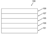
도 1에 관하여, 공지된 충전식 금속 이온 배터리(100)는 전도성 층(101), 예를 들어 금속층; 애노드층(103); 금속 이온을 방출하고 재삽입할 수 있는 캐쏘드층(107); 상기 애노드와 캐쏘드층(103) 및 (107) 사이의 전해질(105); 및 금속층과 같은 전도성 층(109)을 갖는다. 배터리 전지가 완전히 충전되면, 금속 이온이 상기 금속-이온-함유 캐쏘드(107)층으로부터 전해질(105)을 통해 애노드층(103)으로 운반되었다.1, a known rechargeable
상기 애노드층(103)은 전기활성 물질의 입자 및 결합제 물질(본 발명의 어디에서나 사용되는 바와 같은 "활성 물질" 또는 "전기활성 물질"은 금속 이온, 예를 들어 리튬, 나트륨, 칼륨, 칼슘 또는 마그네슘을 배터리의 각각의 충전 단계 및 방전 단계 동안, 그의 구조내에 삽입하고 상기 구조로부터 방출할 수 있는 물질을 의미한다)을 함유할 수 있다.The
리튬 이온 배터리의 그라파이트-기재 애노드층의 경우에, 리튬의 삽입은 화합물 LixC6(0 <= x <= 1)을 형성시킨다. 그라파이트는 372 mAh/g의 최대 정전용량을 갖는다.In the case of the graphite-based anode layer of a lithium ion battery, the insertion of lithium forms the compound Li x C 6 (0 < = x < = 1). The graphite has a maximum capacitance of 372 mAh / g.
규소-기재 활성 애노드 물질의 사용이 또한 당해 분야에 공지되어 있다. 규소는 그라파이트보다 실질적으로 더 높은 최대 정전용량을 갖는다. 그러나, 금속 이온의 삽입 및 방출 동안 실질적으로 변하지 않고 남아있는 활성 그라파이트와 달리, 규소내로의 금속 이온의 삽입 과정은 상당한 구조적 변화를 생성시키고, 상당한 팽창을 동반한다. 예를 들어, 규소내로 리튬 이온의 삽입은 Si-Li 합금을 형성시킨다. 상기 애노드 물질에 대한 Li 이온 삽입의 영향이 예를 들어 문헌["Insertion Electrode Materials for Rechargeable Lithium Batteries", Winter et al, Adv. Mater. 1988, 10, No. 10, pages 725-763]에 개시되어 있다.The use of silicon-based active anode materials is also known in the art. Silicon has a substantially higher maximum capacitance than graphite. However, unlike the active graphite that remains substantially unchanged during the insertion and release of the metal ion, the process of inserting the metal ion into the silicon produces significant structural changes and is accompanied by significant expansion. For example, insertion of lithium ions into silicon forms Si-Li alloys. The effect of Li ion insertion on the anode material is described, for example, in " Insertion Electrode Materials for Rechargeable Lithium Batteries ", Winter et al, Adv. Mater. 1988,10, No. 10, pages 725-763.
US 2009/301866은 고체 지지체, 상기 고체 지지체에 부착되는 제1 고체층 및 상기 제1 고체층에 부착되는 제2 고체층의 다층을 개시하며, 여기에서 상기 제1 및 제2 고체층은 각각 전기화학적으로 활성인 물질의 입자 및 결합제를 함유한다. 상기 제1 및 제2 층은 모두 탄성중합체성 결합제를 포함한다.US 2009/301866 discloses a multilayer of a solid support, a first solid layer attached to the solid support, and a second solid layer adhered to the first solid layer, wherein the first and second solid layers are electrically Containing particles of a chemically active substance and a binder. The first and second layers all comprise an elastomeric binder.
US 2012/040242는 리튬 이온 2차 배터리의 애노드를 개시하며, 상기 애노드는 규소를 함유하는 제1층 및 규소 및 금속 원소를 함유하는 제2층으로 구성된 다층 구조를 갖는다. 상기 금속 원소의 존재는 애노드의 확대 및 수축을 억제시키는 것으로 서술된다.US 2012/040242 discloses an anode of a lithium ion secondary battery, which has a multilayer structure consisting of a first layer containing silicon and a second layer containing silicon and a metallic element. The presence of the metal element is described as inhibiting the expansion and contraction of the anode.
US 7311999는 애노드 집전체의 애노드, 애노드 활성 물질층 및 상기 애노드 활성 물질층상의 산화 규소의 층을 개시한다. 상기 산화 규소의 층은 상기 애노드 활성 물질층과 전해질간의 반응을 억제하기 위해 포함된다.US 7311999 discloses an anode of an anode current collector, a layer of an anode active material, and a layer of silicon oxide on the anode active material layer. The layer of silicon oxide is included to suppress the reaction between the anode active material layer and the electrolyte.
US 7638239는 구리를 함유하는 집전체, 활성 물질 및 상기 집전체와 상기 활성물질 사이의 2개 층으로부터 형성된 완충제의 전극을 개시한다. 상기 완충제는 상기 집전체로부터 상기 활성 물질로의 구리의 과도한 확산, 및 상기 활성 물질로부터 상기 집전체로의 규소의 확산을 방지하기 위해 제공된다.US 7638239 discloses an electrode of a current collector containing copper, an active material and a buffer formed from two layers between said current collector and said active material. The buffer is provided to prevent excessive diffusion of copper from the current collector to the active material and diffusion of silicon from the active material to the current collector.
US 7824801은 집전체, 산소가 없거나 또는 낮은 산소 대 규소비를 갖는 제1 규소층 및 더 높은 산소 대 규소비를 갖는 제2 규소층의 전극을 개시한다. 상기 제1 층은 높은 충전/방전 정전용량 및 높은 전자 전도도를 갖지만, 큰 팽창 계수 및 낮은 이온 전도도를 갖는 것으로 서술된다. 상기 제2 층은 상기 제1 층보다 더 작은 팽창 계수 및 더 낮은 충전/방전 정전용량을 갖지만, 더 높은 이온 전도도를 갖는 것으로 서술된다.US 7824801 discloses an electrode of a current collector, a first silicon layer with no oxygen or low oxygen to silicon content and a second silicon layer with a higher oxygen to silicon content. The first layer has a high charge / discharge electrostatic capacity and a high electronic conductivity, but is described as having a high coefficient of expansion and a low ionic conductivity. The second layer has a lower coefficient of expansion and lower charge / discharge capacitance than the first layer, but is described as having a higher ionic conductivity.
US 8080337은 집전체 및 교번하는 제1 및 제2 층을 개시한다. 상기 제1 층은 활성 물질을 함유한다. 상기 제2 층은 상기 제1 층보다 더 큰 영률을 가지며 전도성이다. 상기 제2 층은 전도성 금속 화합물, 예를 들어 금속 나이트라이드, 금속 카바이드 또는 금속 보라이드일 수 있다.US 8080337 discloses a current collector and alternating first and second layers. The first layer contains the active material. The second layer has a greater Young's modulus than the first layer and is conductive. The second layer may be a conductive metal compound, for example, a metal nitride, a metal carbide or a metal boride.
바람직하게, 본 발명은 개선된 성능을 갖는 에너지 발생 장치, 예를 들어 비제한적으로 금속 이온 배터리를 제공한다.Preferably, the present invention provides an energy generating device with improved performance, such as, but not limited to, a metal ion battery.
본 발명의 첫 번째 태양에 따라, 전도성층, 제1 복합 전극층 및 제2 복합 전극층을 순서대로 포함하는 다층 전극을 제공하며, 각각의 복합 전극층은 금속 이온 배터리에 활성 물질로서 사용하기에 적합한 미립자 물질 및 결합제를 포함하고, 여기에서 상기 제1 복합 전극층의 활성 물질의 주성분(제1 주요 활성 성분)은 상기 제2 복합 전극층의 활성 물질의 주성분(제2 주요 활성 성분)을 형성하는 물질과 상이한 물질이다.According to a first aspect of the present invention there is provided a multilayer electrode comprising in order a conductive layer, a first composite electrode layer and a second composite electrode layer, each composite electrode layer comprising a particulate material suitable for use as an active material in a metal ion battery And a binder, wherein the main component (the first major active component) of the active material of the first composite electrode layer is a material different from the main component (the second main active component) of the active material of the second composite electrode layer to be.
임의로, 상기 다층 전극은 상기 제1 복합층과 상기 제2 복합층 사이에 계면을 포함한다.Optionally, the multilayer electrode comprises an interface between the first composite layer and the second composite layer.
임의로, 상기 제1 및 제2 복합 전극층의 결합제는 상이하다.Optionally, the binders of the first and second composite electrode layers are different.
임의로, 상기 제1 복합 전극층의 결합제는 탄성중합체성 중합체이고, 상기 제2 복합 전극층의 결합제는 비-탄성중합체성 중합체이다.Optionally, the binder of the first composite electrode layer is an elastomeric polymer and the binder of the second composite electrode layer is a non-elastomeric polymer.
임의로, 상기 제2 복합 전극층의 주요 활성 성분의 이론적인 비정전용량은 상기 제1 복합 전극층의 주요 활성 성분의 경우보다 더 높다.Optionally, the theoretical non-capacitance of the major active component of the second composite electrode layer is higher than that of the major active component of the first composite electrode layer.
임의로 하나 또는 각층은 하나 이상의 하위-층들을 포함한다.Optionally, one or each layer comprises one or more sub-layers.
임의로 상기 제1 복합 전극층은 상기 집전체의 영역에 인접하거나 또는 상기 영역 중에 하나 이상의 하부 하위-층을 포함한다. 임의로 상기 제1 복합 전극층은 상기 제1 복합 전극층과 상기 제2 복합 전극층 사이의 계면에 또는 상기 계면의 영역 중에 하나 이상의 상부 하위-층을 포함한다.Optionally, the first composite electrode layer includes one or more lower sub-layers adjacent to or in the region of the current collector. Optionally, the first composite electrode layer comprises one or more upper sub-layers at or near the interface between the first composite electrode layer and the second composite electrode layer.
임의로 상기 제2 복합층은 상기 계면에 인접한 하부 표면 및 상기 계면에서 먼 상부 표면을 포함한다.Optionally, the second composite layer comprises a lower surface adjacent the interface and an upper surface remote from the interface.
임의로 상기 제2 복합층은 상기 제1 복합 전극층과 상기 제2 복합 전극층 사이의 계면에 인접하거나 또는 상기 계면의 영역 중에 하나 이상의 하부 하위-층을 포함한다. 임의로 상기 제2 복합층은 상기 제2 복합 전극층의 상부 표면에 또는 상기 표면의 영역 중에 하나 이상의 상부 하위-층을 포함한다. Optionally, the second composite layer comprises one or more lower sub-layers adjacent to or in the interface between the first composite electrode layer and the second composite electrode layer. Optionally, the second composite layer comprises one or more upper sub-layers on the upper surface of the second composite electrode layer or in the region of the surface.
임의로 하나의 하위-층의 주요 활성 성분의 농도는 상기 다층 전극의 복합층 내의 인접한 하위-층 중의 주요 활성 성분의 농도와 상이하다.Optionally, the concentration of the major active component in one sub-layer is different than the concentration of the major active component in the adjacent sub-layer in the composite layer of the multilayer electrode.
임의로 상기 제1 주요 활성 성분의 농도는 상기 집전체와, 상기 제2 복합 전극층과의 계면 사이에서 감소한다.Optionally, the concentration of the first major active component decreases between the interface between the current collector and the second composite electrode layer.
임의로 상기 제2 활성 성분의 농도는 상기 제1 복합 전극층과의 계면과 상기 제2 복합 전극층의 상부 표면사이의 방향으로 증가한다.Optionally, the concentration of the second active component increases in a direction between the interface with the first composite electrode layer and the upper surface of the second composite electrode layer.
임의로 하나의 하위-층 중의 결합제의 조성은 상기 다층 전극의 한 층내의 인접한 하위-층 중의 결합제의 조성과 상이하다. 임의로 상기 결합제는 탄성중합체성 및 비-탄성중합체성 중합체의 공-중합체를 포함한다. 임의로 상기 결합제는 탄성중합체성 및 비-탄성중합체성 중합체를 포함하는 공-중합체를 90:10 내지 10:90의 비로 포함한다.Optionally, the composition of the binder in one sub-layer is different from the composition of the binder in the adjacent sub-layer in one layer of the multilayer electrode. Optionally, the binder comprises co-polymers of elastomeric and non-elastomeric polymeric polymers. Optionally, the binder comprises a co-polymer comprising an elastomeric and a non-elastomeric polymer in a ratio of 90:10 to 10:90.
임의로 상기 제1 복합 전극층의 다공도는 상기 제2 복합 전극층의 다공도와 상이하다.Optionally, the porosity of the first composite electrode layer is different from the porosity of the second composite electrode layer.
임의로 상기 제1 복합 전극층의 다공도는 상기 제2 복합 전극층의 다공도보다 작다.Optionally, the porosity of the first composite electrode layer is less than the porosity of the second composite electrode layer.
임의로 상기 제1 복합 전극층의 다공도는 5 부피% 초과이다.Optionally, the porosity of the first composite electrode layer is greater than 5% by volume.
임의로 상기 제1 복합 전극층의 다공도는 30 부피% 미만이다.Optionally, the porosity of the first composite electrode layer is less than 30% by volume.
임의로 상기 제1 복합 전극층의 다공도는 20 내지 25 부피%의 범위이다.Optionally, the porosity of the first composite electrode layer ranges from 20 to 25% by volume.
임의로 상기 제2 복합 전극층의 다공도는 20 부피% 초과이다.Optionally, the porosity of the second composite electrode layer is greater than 20% by volume.
임의로 상기 제2 복합 전극층의 다공도는 80 부피% 미만이다.Optionally, the porosity of the second composite electrode layer is less than 80 vol%.
임의로 상기 제2 복합 전극층의 다공도는 30 내지 70 부피%의 범위이다.Optionally, the porosity of the second composite electrode layer ranges from 30 to 70% by volume.
임의로 하나의 하위-층의 다공도는 상기 다층 전극 층 내부의 인접한 하위-층의 다공도와 상이하다.Optionally, the porosity of one sub-layer is different from the porosity of an adjacent sub-layer within the multi-layer electrode layer.
임의로 상기 제2 복합 전극층의 상부 하위-층의 다공도는 하부 하위-층의 다공도보다 작다.Optionally, the porosity of the upper sub-layer of the second composite electrode layer is less than the porosity of the lower sub-layer.
임의로 상기 제1 복합 전극층은 동일하거나 유사한 형태의 입자들을 포함하는 제1 주요 활성 성분을 포함한다. 임의로 상기 제1 복합 전극층은 상이한 형태의 입자를 포함하는 제1 주요 활성 성분을 포함한다.Optionally, the first composite electrode layer comprises a first major active component comprising particles of the same or similar type. Optionally, the first composite electrode layer comprises a first major active component comprising different types of particles.
임의로 상기 제2 복합 전극층은 동일하거나 유사한 형태의 입자들을 포함하는 제2 주요 활성 성분을 포함한다. Optionally, the second composite electrode layer comprises a second major active component comprising particles of the same or similar type.
임의로 상기 제2 복합 전극층은 상이한 형태의 입자를 포함하는 제2 주요 활성 성분을 포함한다.Optionally, the second composite electrode layer comprises a second major active component comprising different types of particles.
임의로 상기 제1 복합층의 주요 활성 성분은 전기활성 탄소를 포함한다. 임의로 상기 전기활성 탄소는 천연 및/또는 인공 그라파이트 또는 경질 탄소이다.Optionally, the primary active component of the first multiple layer comprises electroactive carbon. Optionally, the electroactive carbon is natural and / or artificial graphite or light carbon.
임의로, 상기 제2 복합 전극층의 주요 활성 성분은 규소, 주석, 알루미늄, 납 및 안티몬으로 이루어진 그룹 중에서 선택된다.Optionally, the major active component of the second composite electrode layer is selected from the group consisting of silicon, tin, aluminum, lead and antimony.
임의로, 상기 제2 복합 전극층의 주요 활성 성분의 이론적인 비정전용량은 500 mAh/g 초과이고 상기 제1 복합 전극층의 주요 활성 성분의 이론적인 비정전용량은 400 mAh/g 미만이다.Optionally, the theoretical noncontact capacity of the major active component of the second composite electrode layer is greater than 500 mAh / g and the theoretical noncontact capacity of the major active component of the first composite electrode layer is less than 400 mAh / g.
임의로 하나의 하위-층의 이론적인 비정전용량은 상기 다층 전극 층 내부의 인접한 층의 이론적인 비정전용량과 상이하다.Optionally, the theoretical non-conducting capacity of one sub-layer is different from the theoretical non-conducting capacity of an adjacent layer within the multi-layered electrode layer.
임의로 제2 복합 전극층의 상부 하위-층의 이론적인 비정전용량은 하부 하위-층의 이론적인 비정전용량보다 크다.Optionally, the theoretical non-conducting capacity of the upper sub-layer of the second composite electrode layer is greater than the theoretical non-conducting capacity of the lower sub-layer.
임의로, 상기 제1 복합 애노드층 중의 주요 활성 성분의 농도는 상기 제2 복합 애노드층 중의 주요 활성 성분의 농도보다 크다.Optionally, the concentration of the major active component in the first composite anode layer is greater than the concentration of the major active component in the second composite anode layer.
임의로, 상기 제2 복합 전극층의 주요 활성 성분의 부피 증가 V1은 90% 이상이다.Optionally, the volume increase V 1 of the major active component of the second composite electrode layer is greater than 90%.
임의로, 상기 제2 복합 전극층은 20 g/㎡ 이하의 상기 층의 주요 활성 성분을 함유한다.Optionally, the second composite electrode layer contains the major active component of the layer at 20 g /
임의로, 상기 제1 복합 애노드층의 주요 활성 성분의 부피 증가 V1은 30% 이하이다.Optionally, the volume increase V 1 of the major active component of the first composite anode layer is 30% or less.
임의로, 상기 제2 복합 전극층은 30 g/㎡ 이상의 상기 층의 주요 활성 성분을 함유한다.Optionally, the second composite electrode layer contains 30 g / m < 2 > or more of the major active component of the layer.
임의로, 도핑되거나 도핑되지 않은 규소는 상기 제2 복합 전극층의 주요 활성 성분이고 활성 탄소는 상기 제1 복합 전극층의 주요 활성 성분이다.Optionally, the doped or undoped silicon is the major active component of the second composite electrode layer and the activated carbon is the major active component of the first composite electrode layer.
임의로, 활성 탄소는 경질 탄소, 탄소 나노-튜브 및 그라파이트 중 하나 이상으로부터 선택된다.Optionally, the activated carbon is selected from at least one of light carbon, carbon nano-tube and graphite.
임의로 상기 그라파이트는 천연 또는 합성 그라파이트를 포함한다. 임의로 상기 그라파이트는 박편, 중간-탄소 미세-비드 및 큰 인공 그라파이트의 형태로 제공된다. 작은, 중간 및 큰 탄소 박편을 임의로 사용할 수도 있다.Optionally, the graphite comprises natural or synthetic graphite. Optionally, the graphite is provided in the form of flakes, medium-carbon micro-beads and large artificial graphites. Small, medium and large carbon flakes may optionally be used.
임의로 상기 그라파이트는 중간-탄소 미세-비드를 포함한다.Optionally, the graphite comprises medium-carbon micro-beads.
임의로 상기 활성 탄소는 탄소 나노-튜브 및 탄소 섬유와 같은 연장물(elongate)을 포함한다.Optionally, the activated carbon comprises carbon nanotubes and elongates such as carbon fibers.
임의로 상기 활성 탄소는 경질 탄소를 포함한다. 임의로, 상기 활성 탄소는 상기 제1 복합 전극층의 유일한 주요 활성 성분이다.Optionally, the activated carbon comprises light carbon. Optionally, the activated carbon is the only major active component of the first composite electrode layer.
임의로, 도핑되거나 도핑되지 않은 규소는 상기 제2 복합 전극층의 유일한 활성 성분이다.Optionally, the doped or undoped silicon is the only active component of the second composite electrode layer.
임의로 상기 활성 규소는 박편, 입자, 섬유, 리본, 스캐폴드 구조, 튜브 및 이들의 혼합물을 포함한다. 임의로, 상기 활성 규소 입자는 고유 입자, 필러가 있는 입자, 다공성 입자, 다공성 입자 단편 및 이들의 혼합물을 포함한다. 임의로, 상기 입자는 회전타원형, 입방형, 연장물 또는 구형의 모양이다. 임의로, 상기 제2 복합 전극층은 하나 이상의 추가의 활성 물질을 포함한다. 임의로 상기 추가의 활성 물질은 활성 탄소 물질이다.Optionally, the active silicon includes flakes, particles, fibers, ribbons, scaffold structures, tubes, and mixtures thereof. Optionally, the active silicon particles include eigenparticles, particles with fillers, porous particles, porous particle fragments, and mixtures thereof. Optionally, the particles are in the form of a spheroidal, oval, cubic, elongated or spherical shape. Optionally, the second composite electrode layer comprises one or more additional active materials. Optionally, the further active material is an activated carbon material.
임의로, 상기 제1 복합 전극층의 결합제는 PVDF이다. 임의로 상기 제1 복합층의 결합제는 폴리이미드이다.Optionally, the binder of the first composite electrode layer is PVDF. Optionally, the binder of the first composite layer is polyimide.
임의로, 상기 제2 복합 전극층의 결합제는 PAA 또는 그의 염이다. 임의로 상기 제2 복합 전극층의 결합제는 카복시메틸셀룰로스(CMC) 또는 그의 염, 스타이렌 부타다이엔 고무(SBR) 또는 이들의 2원 또는 3원 혼합물이다.Optionally, the binder of the second composite electrode layer is PAA or a salt thereof. Optionally, the binder of the second composite electrode layer is carboxymethylcellulose (CMC) or a salt thereof, styrene butadiene rubber (SBR), or a binary or ternary mixture thereof.
임의로 상기 제1 복합층의 결합제는 PVDF와 PAA의 혼합물 또는 공중합체를 포함하며, 여기에서 상기 PVDF 및 PAA는 90:10 내지 55:45의 범위로 존재한다.Optionally, the binder of the first composite layer comprises a mixture or copolymer of PVDF and PAA, wherein the PVDF and PAA are present in the range of 90:10 to 55:45.
임의로 상기 제2 복합층의 결합제는 PVDF와 PAA의 혼합물 또는 공중합체를 포함하며, 여기에서 상기 PVDF 및 PAA는 10:90 내지 45:55의 범위로 존재한다.Optionally, the binder of the second composite layer comprises a mixture or copolymer of PVDF and PAA, wherein the PVDF and PAA are present in the range of 10:90 to 45:55.
임의로 상기 제1 복합층이나 상기 제2 복합층의 결합제는 PVDF 및 PAA의 혼합물을 포함한다. 임의로 상기 제1 복합층의 결합제는 PVDF 및 PAA를 포함하고, 여기에서 상기 PVDF 및 PAA는 90:10 내지 55:45의 비로 존재한다. 임의로 상기 제2 복합층의 결합제는 PVDF 및 PAA를 포함하고, 여기에서 상기 PVDF 및 PAA는 10:90 내지 55:45의 비로 존재한다. Optionally, the binder of the first composite layer or the second composite layer comprises a mixture of PVDF and PAA. Optionally, the binder of the first composite layer comprises PVDF and PAA, wherein the PVDF and PAA are present in a ratio of 90:10 to 55:45. Optionally, the binder of the second composite layer comprises PVDF and PAA, wherein the PVDF and PAA are present in a ratio of 10:90 to 55:45.
임의로 상기 제1 복합층이나 상기 제2 복합층의 결합제는 폴리이미드(PI) 및 카복시메틸셀룰로스(CMC) 또는 스타이렌 부타다이엔 고무(SBR)의 혼합물을 포함한다. 임의로 상기 제1 복합층의 결합제는 폴리이미드 및 CMC/SBR을 포함하며, 여기에서 상기 PI 및 CMC/SBR은 90:10 내지 55:45의 비로 존재한다. 임의로 상기 제2 복합층의 결합제는 PI 및 CMC/SBR을 포함하며, 여기에서 상기 PI 및 CMC/SBR은 10:90 내지 55:45의 비로 존재한다. Optionally, the binder of the first composite layer or the second composite layer comprises a mixture of polyimide (PI) and carboxymethyl cellulose (CMC) or styrene butadiene rubber (SBR). Optionally, the binder of the first composite layer comprises polyimide and CMC / SBR, wherein the PI and CMC / SBR are present in a ratio of 90:10 to 55:45. Optionally, the binder of the second composite layer comprises PI and CMC / SBR, wherein the PI and CMC / SBR are present in a ratio of 10:90 to 55:45.
임의로, 상기 제1 복합 전극층을 상기 전도성 층 위에 형성시킨다.Optionally, the first composite electrode layer is formed on the conductive layer.
임의로, 상기 제2 복합 전극층을 상기 제1 복합 전극층 위에 형성시킨다.Optionally, the second composite electrode layer is formed on the first composite electrode layer.
임의로, 상기 제1 및 제2 전극 사이에 접착층을 제공한다.Optionally, an adhesive layer is provided between the first and second electrodes.
임의로 상기 접착층은 탄성중합체성 및 비-탄성중합체성 중합체의 혼합물을 포함한다.Optionally, the adhesive layer comprises a mixture of elastomeric and non-elastomeric polymeric polymers.
임의로, 접착층은 전도성 탄소를 추가로 포함한다. 임의로 상기 전도성 탄소는 탄소 섬유, 탄소 나노-튜브, 켓젠 블랙, 램프 블랙, 아세틸렌 블랙, 피치 블랙, 그래핀 및 이들의 혼합물을 포함한다.Optionally, the adhesive layer further comprises conductive carbon. Optionally, the conductive carbon includes carbon fibers, carbon nano-tubes, Ketjen black, lamp black, acetylene black, pitch black, graphene, and mixtures thereof.
임의로, 상기 복합 전극층들 중 하나 이상은 전도성 미립자 첨가제를 추가로 포함한다. 임의로, 상기 전도성 미립자는 탄소 섬유, 탄소 나노-튜브, 켓젠 블랙, 램프 플랙, 아세틸렌 블랙, 그래핀 및 피치 블랙을 포함한다.Optionally, at least one of the composite electrode layers further comprises a conductive particulate additive. Optionally, the conductive fine particles include carbon fibers, carbon nano-tubes, Ketjen black, lamp flakes, acetylene black, graphene and pitch black.
본 발명의 두 번째 태양에서, 본 발명의 첫 번째 태양에 따른 애노드를 포함하는 금속 이온 배터리를 제공한다.In a second aspect of the present invention, there is provided a metal ion battery including an anode according to the first aspect of the present invention.
본 발명의 세 번째 태양에서, 제1 복합 전극층을 전도성 층 위에 형성시키고; 제2 복합 전극층을 상기 제1 복합 전극층 위에 형성시키는 단계들을 포함하는, 본 발명의 첫 번째 태양에 따른 다층 전극의 형성 방법을 제공한다.In a third aspect of the invention, a first composite electrode layer is formed over the conductive layer; And forming a second composite electrode layer on the first composite electrode layer according to the first aspect of the present invention.
임의로, 상기 세 번째 태양의 제1 및 제2 복합 전극층을 각각, 상기 복합 전극층의 성분들 및 하나 이상의 용매를 포함하는 슬러리를 침착시키고, 상기 하나 이상의 용매를 증발시킴으로써 형성시킬 수 있다.Optionally, the first and second composite electrode layers of the third aspect may be formed by depositing a slurry comprising components of the composite electrode layer and at least one solvent, respectively, and evaporating the at least one solvent.
임의로 접착층을 상기 제1 복합층과 상기 제2 복합층 사이에 침착시킨다. 임의로 상기 접착층은 탄소 섬유, 중합체성 섬유, 금속 섬유 또는 이들의 혼합물을 포함한다.Optionally an adhesive layer is deposited between the first composite layer and the second composite layer. Optionally, the adhesive layer comprises carbon fibers, polymeric fibers, metal fibers or mixtures thereof.
임의로 상기 제1 및 제2 복합 전극층을 닥터 블레이드 코팅, 정전기 코팅 기법, 예를 들어 분말 코팅, 회전 코팅, 분무 코팅, 수직 코팅, 딥 코팅 및 화학적 증착 중에서 선택된 하나 이상의 방법을 사용하여 침착시킨다.Optionally, the first and second composite electrode layers are deposited using one or more methods selected from doctor blade coating, electrostatic coating techniques such as powder coating, spin coating, spray coating, vertical coating, dip coating and chemical vapor deposition.
임의로, 본 발명의 세 번째 태양에서, 상기 하나 이상의 용매의 증발 도중에 또는 상기 증발 후에 적어도 상기 제1 복합 전극층에 압력을 적용시킬 수 있다.Optionally, in a third aspect of the invention, pressure may be applied to at least the first composite electrode layer either during or after evaporation of the one or more solvents.
임의로, 본 발명의 세 번째 태양에서, 압력을 캘린더링에 의해 적용할 수 있다.Optionally, in the third aspect of the invention, the pressure can be applied by calendering.
임의로, 본 발명의 세 번째 태양에서, 제1 압력을 상기 제2 복합 전극층의 형성 전에 상기 제1 복합 전극층에 적용할 수 있으며, 상기 제2 복합 전극층에 압력을 적용하지 않거나 제2 압력을 적용할 수도 있고, 여기에서 상기 제2 압력은 상기 제1 압력보다 낮다.Optionally, in a third aspect of the present invention, a first pressure may be applied to the first composite electrode layer prior to formation of the second composite electrode layer, wherein no pressure is applied to the second composite electrode layer, or a second pressure is applied And wherein the second pressure is lower than the first pressure.
임의로, 본 발명의 세 번째 태양에서, 상기 제1 복합 전극층의 결합제는 상기 제2 복합 전극층의 형성에 사용되는 슬러리의 용매 또는 용매 혼합물 중에 불용성이다.
Optionally, in the third aspect of the present invention, the binder of the first composite electrode layer is insoluble in the solvent or solvent mixture of the slurry used to form the second composite electrode layer.
이제 본 발명을 도면을 참조하여 보다 상세히 개시할 것이며, 도면에서:
도 1은 종래 기술의 금속 이온 배터리를 예시하고;
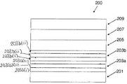
도 2a는 2개의 애노드층을 갖는 본 발명의 하나의 실시태양에 따른 금속 이온 배터리를 예시하고;
도 2b는 각 층이 2개 이상의 하위-층을 포함하는, 2개의 애노드층을 갖는 실시태양에 따른 금속 이온 배터리를 예시하고;
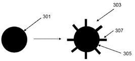
도 3a 및 3b는 필러가 있는 입자의 형성 방법을 예시하고;
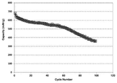
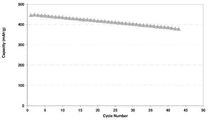
도 4는 본 발명의 하나의 실시태양에 따른 하이브리드 반쪽 전지의 정전용량을 예시하고;
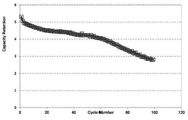
도 5는 본 발명의 하나의 실시태양에 따른 하이브리드 반쪽 전지의 정전용량 보존을 예시하고;
도 6은 본 발명의 하나의 실시태양에 따른 이중-층 애노드 및 리튬 캐쏘드를 포함하는 반쪽 전지의 정전용량을 예시하고;
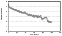
도 7은 본 발명의 하나의 실시태양에 따른 전체 이중-층 전지의 정전용량 보존을 예시하고;
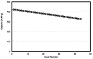
도 8은 본 발명의 하나의 실시태양에 따른 이중-층 전체 전지의 이중-층에 대한 정전용량 대 주기수를 예시하고;
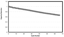
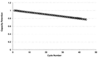
도 9는 본 발명의 하나의 실시태양에 따른 이중-층 전체 전지에 대한 정전용량 보존 대 주기수를 예시하고;
도 10은 본 발명의 하나의 실시태양에 따른 이중-층 반쪽 전지에 대한 정전용량 대 주기수를 예시하고;
도 11은 본 발명의 하나의 실시태양에 따른 이중-층 반쪽 전지에 대한 정전용량 보존 대 주기수를 예시하고;
도 12는 본 발명의 하나의 실시태양에 따른 이중-층 전체 전지에 대한 정전용량 대 주기수를 예시하고;
도 13은 본 발명의 하나의 실시태양에 따른 이중-층 전체 전지에 대한 정전용량 보존 대 주기수를 예시하고;
도 14는 본 발명의 하나의 실시태양에 따른 이중-층 전체 전지에 대한 정전용량 대 주기수를 예시하고;
도 15는 본 발명의 하나의 실시태양에 따른 이중-층 전체 전지에 대한 정전용량 보존 대 주기수를 예시하고;
도 16은 본 발명의 하나의 실시태양에 따른 이중-층 반쪽 전지에 대한 정전용량 대 주기수를 예시하고;
도 17은 본 발명의 하나의 실시태양에 따른 이중-층 반쪽 전지에 대한 정전용량 보존 대 주기수를 예시하고;
도 18은 본 발명의 하나의 실시태양에 따른 이중-층 전체 전지에 대한 정전용량 대 주기수를 예시하고;
도 19는 본 발명의 하나의 실시태양에 따른 이중-층 전체 전지에 대한 정전용량 보존 대 주기수를 예시한다.The present invention will now be described in more detail with reference to the drawings, in which:
Figure 1 illustrates a prior art metal ion battery;
Figure 2A illustrates a metal ion battery according to one embodiment of the present invention having two anode layers;
Figure 2b illustrates a metal ion battery according to an embodiment having two anode layers, each layer comprising two or more sub-layers;
Figures 3a and 3b illustrate a method of forming particles with fillers;
Figure 4 illustrates the capacitance of a hybrid half-cell according to one embodiment of the present invention;
Figure 5 illustrates the storage of capacitance of a hybrid half-cell according to one embodiment of the present invention;
Figure 6 illustrates the capacitance of a half-cell comprising a dual-layer anode and a lithium cathode according to one embodiment of the present invention;
Figure 7 illustrates the capacitance storage of an entire dual-layer cell in accordance with one embodiment of the present invention;
Figure 8 illustrates the capacitance vs. period number for a double-layer of a dual-layer overall cell in accordance with one embodiment of the present invention;
Figure 9 illustrates the capacitance conservation period number for a dual-layer full battery in accordance with one embodiment of the present invention;
Figure 10 illustrates the capacitance versus number of cycles for a dual-layer half-cell according to one embodiment of the present invention;
Figure 11 illustrates the capacitance conservation period number for a dual-layer half-cell according to one embodiment of the present invention;
Figure 12 illustrates the capacitance vs. period number for a dual-layer full battery in accordance with one embodiment of the present invention;
Figure 13 illustrates the capacitance conservation period number for a dual-layer full battery in accordance with one embodiment of the present invention;
Figure 14 illustrates the capacitance vs. period number for a dual-layer overall cell in accordance with one embodiment of the present invention;
Figure 15 illustrates the capacitance conservation period number for a dual-layer full battery in accordance with one embodiment of the present invention;
Figure 16 illustrates the capacitance vs. period number for a dual-layer half-cell according to one embodiment of the present invention;
Figure 17 illustrates the capacitance conservation period number for a dual-layer half-cell according to one embodiment of the present invention;
Figure 18 illustrates the capacitance vs. period number for a dual-layer full battery in accordance with one embodiment of the present invention;
Figure 19 illustrates the capacitance conservation period number for a dual-layer full battery in accordance with one embodiment of the present invention.
도 2a는 본 발명의 하나의 실시태양에 따른 충전식 금속 이온 배터리(200)를 예시한다. 상기 배터리(200)는 전도성 애노드 집전체층(201), 예를 들어 금속의 층; 제1 복합 애노드층(203a); 제2 복합 애노드층(203b); 금속 이온을 방출 및 재삽입할 수 있는 캐쏘드층(207); 상기 애노드층(203a) 및 (203b) 및 캐쏘드층(207) 사이의 전해질(205); 및 전도성 층(209), 예를 들어 금속의 층을 갖는다.2A illustrates a rechargeable
복합 애노드층(203a) 및 (203b)는 각각 적어도 결합제 및 하나 이상의 전기활성 물질의 입자를 함유한다. 애노드층(203a) 및 (203b)는 상이한 조성을 갖는다. 상기 애노드층(203a) 및 (203b)는 각각의 복합층을 형성하는 물질들의 비 중 하나 이상, 또는 각각의 복합층을 형성하는 물질들 중 하나 이상이 상이할 수 있다. 복합 애노드층(203a) 및 (203b)는 각각 결합제 및 하나 이상의 전기활성 물질로 필수적으로 이루어지거나, 또는 하나 이상의 추가의 성분들, 예를 들어 하나 이상의 비-활성 전도성 물질, 예를 들어 카본 블랙의 입자를 함유할 수 있다.
상기 제1 및 제2 복합 애노드층(203a) 및 (203b)의 주요 활성 성분은 상이하다(본 발명에 사용되는 바와 같은 "주요 활성 성분"으로서 층 중에 존재하는 물질은 상기 물질이 상기 층 중의 상기 활성 물질(들)의 50 중량% 초과 100 중량% 이하, 임의로 상기 층 중의 상기 활성 물질의 51 내지 100 중량%, 60 내지 100 중량%, 75 내지 100 중량% 또는 90 내지 100 중량%를 형성함을 의미한다). 본 발명에서, 상기 제1 및 제2 복합층 중에 존재하는 물질들은 그들의 고유 정전용량, 및 금속 삽입시 부피 증가 중 어느 하나 또는 둘 다가 상이한 경우 "상이한" 것으로 간주될 수 있다.The major active components of the first and second
동일한 활성 물질이 상기 두 복합 애노드층(203a) 및 (203b) 중에 존재할 수 있으나, 단 상기 물질은 하나의 애노드층 중에 주요 활성 성분으로서 존재하고 다른 애노드층 중에서는 단지 부 활성 성분으로서만 존재해야 하거나, 또는 동일한 활성 물질이 상기 두 층 모두 중에 부 활성 성분으로서 제공되어야 한다. 부 활성 성분은 층의 활성 물질의 0.5 내지 20 중량% 이하를 구성할 수 있다. 부 활성 성분은 애노드층의 전체 중량의 0.5 내지 10 중량%를 구성할 수 있다.The same active material may be present in the two
상기 주요 활성 성분은 복합 애노드층의 전체 중량의 50 내지 98 중량%, 임의로 50 내지 90 중량%를 구성할 수 있고, 나머지 중량은 상기 결합제 및 임의의 다른 성분, 예를 들어 하나 이상의 부 활성 성분 및 비-활성 전도성 첨가제로 구성된다.The major active ingredient may constitute from 50 to 98% by weight, optionally from 50 to 90% by weight, of the total weight of the composite anode layer, and the balance weight comprises the binder and any other ingredients, Non-active conductive additive.
도 2b는 각각의 층(203a) 및 (203b)가 하위-층들 203a(i), 203a(ii), 203a(iii)...., 203a(n), 203b(i), 203b(ii), 203b(iii), 203b(n)을 포함할 수 있음을 예시한다. 층 내의 각 하위-층의 주요 활성 성분들은 동일하다. 하위-층 중의 주요 활성 성분의 농도는 인접한 하위-층 중의 주요 활성 성분의 농도와 동일하거나 상이할 수 있다. 그러나, 하위-층 중의 주요 활성 성분의 농도는 인접한 하위-층의 경우와 상이할 수 있으나, 단 전체 하위-층들에 대한 주요 활성 성분의 평균 농도는 전체로서 상기 층 중의 주요 활성 성분의 농도에 상응해야 한다. 각 하위-층의 이론적인 고유 정전용량은 인접한 하위-층의 경우와 상이할 수도 있다.Figure 2b illustrates that each of the
예시적인 활성 물질은 그라파이트, 경질 탄소, 규소, 주석, 게르마늄, 갈륨, 납, 알루미늄, 비스무스 및 아연을 포함한다. 바람직한 실시태양에서, 제1 및 제2 활성 물질을 그라파이트-함유 및 규소-함유 활성 물질로부터 선택할 수 있다. 상기 제1 및 제2 활성 물질은 독립적으로, 도핑되지 않거나 또는 p- 또는 n-도핑된 그라파이트 또는 규소를 포함하여, 그라파이트 또는 규소로 필수적으로 이루어질 수 있다. 상기 제1 및 제2 활성 물질은 각각 독립적으로 복합 물질일 수도 있다.Exemplary active materials include graphite, hard carbon, silicon, tin, germanium, gallium, lead, aluminum, bismuth and zinc. In a preferred embodiment, the first and second active materials can be selected from graphite-containing and silicon-containing active materials. The first and second active materials may be made independently of graphite or silicon, including undoped or p- or n-doped graphite or silicon. The first and second active materials may each independently be a composite material.
활성 그라파이트는 현저한 정전용량의 상실 없이 활성 규소보다 더 큰 수의 충전/방전 주기를 제공할 수 있는 반면, 규소는 그라파이트보다 더 큰 정전용량을 제공할 수 있다. 따라서, 규소-함유 활성 물질 및 그라파이트 활성 물질을 포함하는 전극 조성물은 높은 정전용량 및 큰 수의 충전/방전 주기 모두의 이점을 갖는 리튬 이온 배터리를 제공할 수 있다.Active graphite can provide a greater number of charge / discharge cycles than active silicon without loss of significant capacitance, while silicon can provide greater capacitance than graphite. Thus, an electrode composition comprising a silicon-containing active material and a graphite active material can provide a lithium ion battery having the advantages of both high capacitance and a large number of charge / discharge cycles.
바람직한 실시태양에서, 상기 제1 및 제2 복합 애노드층 중 하나의 주요 활성 성분은 규소-함유 활성 물질(도핑되거나 도핑되지 않은 규소로 필수적으로 이루어지는 물질, 및 도핑되거나 도핑되지 않은 규소 및 하나 이상의 추가적인 물질을 함유하는 복합 활성 물질 포함)이고, 상기 제1 및 제2 복합 애노드층 중 다른 하나의 활성 물질의 주요 활성 성분은 그라파이트이다.In a preferred embodiment, the major active component of one of the first and second composite anode layers is a silicon-containing active material (a material that is essentially doped or undoped silicon, and doped or undoped silicon and one or more additional And the major active ingredient of the active material of the other of the first and second composite anode layers is graphite.
바람직하게 상기 제1 복합층은 주요 활성 성분으로서 그라파이트를 포함하고 상기 제2 복합층은 주요 활성 성분으로서 규소를 포함한다.Preferably, the first composite layer comprises graphite as a major active component and the second composite layer comprises silicon as a major active component.
상기 결합제는 상기 복합 애노드 전극의 입자들에 대한 밀착을 제공하며 그 자체로서 상기 복합 애노드 전극층 밖으로의 입자의 이동을 방지하고/하거나 결합제가 없는 복합 애노드 전극층에 비해 상기 복합 애노드 전극층의 탈층을 감소시키는 작용을 할 수 있다. 본 발명자들은 활성 물질이 상이한 결합제들과 상이한 양립성을 가질 수도 있음을 발견하였다. "양립성"이란 용어는 본 발명에 개시된 주요 활성 성분들 중 하나 및 결합제를 포함하는 복합 물질로부터 제조된 전지가 50회의 충전/방전 주기에 걸쳐 10%를 초과하는 방전 정전용량의 손실을 나타내지 않음을 의미하는 것으로 이해해야 한다.The binder provides adhesion to the particles of the composite anode electrode and as such prevents migration of particles outside the composite anode electrode layer and / or reduces de-layering of the composite anode electrode layer as compared to a composite anode electrode layer without a binder . The present inventors have found that the active material may have different compatibility with different binders. The term "compatible" means that a battery made from a composite material comprising one of the major active ingredients disclosed herein and a binder does not exhibit a loss of discharge capacitance greater than 10% over 50 charge / discharge cycles It should be understood as meaning.
본 발명자들은 활성 물질들을 다수의 복합 애노드층으로 분류함을 사용하여 장치 성능을 증대시킬 수 있음을 발견하였다. 각각의 층이 인접한 층의 주요 활성 성분과 상이한 주요 활성 성분을 포함하는 다층 복합 전극을 포함하는 배터리 전지는, 상기 주요 활성 성분들 중 하나와 효율적으로 결합할 수 있는 결합제는 다른 주요 활성 성분과 효율적으로 결합할 수 없기 때문에, 상기 주요 활성 성분들의 혼합물을 포함하는 단일의 복합층을 포함하는 배터리에 비해 증대된 충전 방전 정전용량 특성을 나타낸다. 상기 결합제의 성질을, 상기 결합제가 일부를 형성하는 층의 조성에 맞출 수 있다. 예를 들어, 하나의 층 또는 하위-층이, 제1 결합제와 양립성이고 제2 결합제 및 제2 전기활성 성분(상기는 제2 결합제와는 양립성이나 제1 결합제와는 비양립성이다)과는 비양립성인 제1 주요 전기활성 성분의 혼합물을 포함하는 경우, 상기 층에 대한 결합제는 상기 제1 및 제2 결합제의 공중합체이거나 또는 혼합물 일 수 있으며; 상기 혼합물 또는 공중합체 중의 상기 제1 및 제2 결합제 성분의 상대적인 비율은 부분적으로 상기 제1 주요 및 제2 전기활성 성분이 상기 층 또는 하위-층내에 존재하는 상대적인 비율에 따라 변할 것이다. 층의 주요 성분은 상기 성분이 일부를 형성하는 층의 50 중량%를 초과하기 때문에, 상기 결합제 조성물은 일반적으로, 상기 주요 전기활성 성분과 양립성인 결합제를 50 중량%를 초과하여 포함하는 혼합물 또는 공중합체를 포함할 것이다.The present inventors have found that classifying active materials into multiple composite anode layers can be used to enhance device performance. A battery cell comprising a multi-layer composite electrode wherein each layer comprises a major active component different from the major active component of the adjacent layer, characterized in that the binder capable of efficiently binding with one of the major active components Exhibits increased charge-discharge electrostatic capacity characteristics over batteries comprising a single composite layer comprising a mixture of the major active components. The properties of the binder can be tailored to the composition of the layer in which the binder is formed. For example, if one layer or sub-layer is compatible with the first binder and the second binder and the second electroactive component (which is compatible with the second binder but incompatible with the first binder) When comprising a mixture of first major electroactive components which are compatible, the binder for said layer may be a copolymer or a mixture of said first and second binders; The relative proportions of the first and second binder components in the mixture or copolymer will vary in part depending on the relative proportions in which the first and second electroactive components are present in the layer or sub-layer. Because the major component of the layer exceeds 50% by weight of the layer in which the component forms a part, the binder composition generally comprises a mixture comprising more than 50% by weight of a binder compatible with the major electroactive component, Will include coalescence.
중합체들의 혼합물을 사용하여 제1 주요 전기활성 성분 및 제2 전기활성 성분을 포함하는 복합 전극층을 제조하는 경우, 상기 결합제는 적합하게는 상기 제1 주요 활성 성분과 양립성인 결합제를 50 내지 100 중량%, 바람직하게는 60 내지 90 중량% 및 특히 70 내지 80 중량%로 포함한다.When a mixture of polymers is used to produce a composite electrode layer comprising a first major electroactive component and a second electroactive component, the binder suitably comprises from 50 to 100% by weight of a binder compatible with the first major active component, By weight, preferably 60 to 90% by weight and especially 70 to 80% by weight.
중합체들의 혼합물을 사용하여 제2 주요 전기활성 성분 및 제1 전기활성 성분을 포함하는 복합 전극층을 제조하는 경우, 상기 결합제는 적합하게는 상기 제2 주요 활성 성분과 양립성인 결합제를 50 내지 100 중량%, 바람직하게는 60 내지 90 중량% 및 특히 70 내지 80 중량%로 포함한다.When preparing a composite electrode layer comprising a second major electroactive component and a first electroactive component using a mixture of polymers, the binder suitably comprises from 50 to 100% by weight of a binder compatible with the second major active component, By weight, preferably 60 to 90% by weight and especially 70 to 80% by weight.
바람직한 배열에서, 상기 제1 복합 애노드층(203a)의 주요 활성 성분은 금속 삽입시 상기 제2 복합 애노드층의 주요 활성 성분보다 더 작은 부피 증가를 겪는다.In a preferred arrangement, the major active component of the first
일련의 활성 물질들에 대한 부피 변화를 표 1에 제공한다. 표 1의 부피 백분율 값은 리튬 삽입시 상기 활성 물질의 이론적인 비정전용량에 대한 상기 활성 물질의 부피 증가(V1)와 관련되며, 부피 증가에 따른 전체 부피는 V0 + V1이고, 여기에서 V0는 임의의 리튬 삽입 전의 활성 물질의 부피이다. 상기 부피 증가 V1은 충전 전후의 전극 물질의 단위 부피를 비교함으로써 측정된다.Volume changes for a series of active materials are provided in Table 1. The volume percentage values in Table 1 are related to the volume increase (V 1 ) of the active material with respect to the theoretical non-reactive capacity of the active material upon lithium insertion, and the total volume with volume increase is V 0 + V 1 V 0 is the volume of active material before any lithium insertion. The volume increase V 1 is measured by comparing the unit volume of the electrode material before and after charging.
[표 1][Table 1]

임의로, 상기 제2 복합 애노드층의 주요 활성 성분의 부피 증가 V1은 90% 이상이고(즉 부피가 원래 부피 V0의 190% 이상까지 증가한다), 임의로 300% 이하이다.Optionally, the volume increase V 1 of the major active component of the second composite anode layer is at least 90% (i.e., the volume increases to at least 190% of the original volume V 0 ), optionally less than or equal to 300%.
임의로, 상기 제1 복합 애노드층의 주요 활성 성분의 부피 증가 V1은 30% 이하, 바람직하게는 5 내지 30%의 범위이다.Optionally, the volume increase V 1 of the major active component of the first composite anode layer is in the range of 30% or less, preferably 5 to 30%.
따라서, 팽창 정도 및 팽창과 관련된 손해 효과가 본 발명에 따른 다층 전극의 형성을 통해 감소될 수 있음을 알 것이다. 30%를 초과하지 않는 부피 증가를 갖는 제1 또는 하부층 및 90% 이상의 부피 증가를 갖는 제2 상부층을 포함하는 전극은 상기 전극을 포함하는 배터리 전지의 충전 및 방전 단계 동안 탈층되거나 또는 기복으로서 공지된 현상을 나타내는 경향이 없다(기복은 상기 전극 덩어리가 전체로서, 상기 충전 및 방전 과정의 결과로서 기판으로부터 멀리 이동하는 과정을 의미하는 것으로 이해해야 한다). 상부층에 비해 하부층의 보다 작은 부피 증가는, 상기 상부층상에 발휘되는 압력이, 상기 하부층이 충전시 보다 큰 부피 증가를 갖는 물질 또는 보다 큰 부피 증가를 갖는 물질과 보다 작은 부피 증가를 갖는 물질의 혼합물을 포함하는 경우에 있게 되는 경우보다 더 작음을 의미하며; 전극층 내의 압력 형성은 상기 팽창의 결과로서 상기 전극내 응력의 형성이 상기 물질을 균열되게 하기 때문에 탈층의 원인이 된다.Thus, it will be appreciated that the degree of expansion and the damaging effects associated with expansion can be reduced through the formation of the multilayer electrode in accordance with the present invention. An electrode comprising a first or bottom layer having a volume increase of not more than 30% and a second top layer having a volume increase of at least 90% may be formed during the filling and discharging of the battery cell comprising the electrode, (Undulation should be understood to mean the process by which the electrode agglomerates as a whole move away from the substrate as a result of the charging and discharging process). The smaller volume increase of the lower layer relative to the upper layer is achieved by the fact that the pressure exerted on the upper layer is greater than the mass of the substance having a larger volume increase or greater ≪ / RTI > is meant to be smaller than when it is present; The formation of pressure in the electrode layer is a cause of delamination because the formation of stresses in the electrode as a result of the expansion causes the material to crack.
전극층 내의 응력의 형성을, 2개 이상의 하위-층들로부터 각각의 복합층을 형성시킴으로써 추가로 감소시킬 수 있다. 바람직하게 각각의 하위-층은 그의 인접한 하위-층의 조성과 상이한 조성을 갖는다. 바람직하게 각각의 하위-층은 50 중량% 초과의 상기 층에 대한 주요 활성 성분을 포함한다. 바람직하게 각 하위-층 중의 주요 활성 성분의 농도는 인접한 하위-층의 경우에 대해 집전체에 수직 방향으로 증가하거나 감소한다.Formation of stress in the electrode layer can be further reduced by forming each composite layer from two or more sub-layers. Preferably each sub-layer has a composition that is different from that of its adjacent sub-layer. Preferably each sub-layer comprises greater than 50% by weight of the major active ingredient for said layer. Preferably, the concentration of the major active component in each sub-layer increases or decreases in the direction perpendicular to the current collector for the case of the adjacent sub-layer.
제1 복합층은 50 중량% 초과의 제1 주요 전기활성 성분을 포함하며, 상기 성분은 90% 이상의 부피 증가를 나타내는 제2 전기활성 성분의 30% 이하 및 40 중량% 이하의 부피 증가를 나타낸다. 바람직하게 상기 제1 주요 전기활성 성분은 상기 제1 복합층의 60 중량% 초과, 바람직하게는 70 중량% 초과, 특히 75 중량% 초과를 차지한다. 바람직하게, 상기 제2 전기활성 성분은 30 중량% 이하, 바람직하게는 20 중량% 이하를 차지한다. 적합하게 상기 제2 전기활성 성분은 상기 제1 복합층의 1 중량% 이상, 바람직하게는 2 중량% 이상 및 특히 10 중량% 이상을 차지한다. 상기 제1 복합층은 하위-층들을 포함할 수 있다. 각 하위-층 중의 상기 제1 주요 전기활성 성분의 농도는 적합하게는 하위-층에서 하위-층으로 통과시 상기 집전체에 수직 방향으로 감소한다. 상기 제2 전기활성 성분의 농도는 하위-층에서 하위-층으로 통과시 동일하게 남아있거나 증가할 수도 있다. 이러한 층들의 배열은, 본 발명의 첫 번째 태양에 따른 전극을 포함하는 배터리 전지의 충전시, 하부 인접한 하위-층에 비해 상부 하위-층의 팽창의 보다 큰 점증적인 증가가 존재함을 의미한다. 그 결과, 상기 전극층 내 압력의 형성이 전체적으로 감소하고, 내부 응력이 최소화되며, 상기 전극은 상기 전극을 포함하는 배터리 전지의 수명에 걸쳐 보다 안정한 양상을 나타낸다. 또한 상기 전지의 단위부피당 정전용량은, 상기 제1 복합층이 상기 제2 복합층의 어떠한 주요 전기활성 성분도 함유하지 않는 상황에 비해 증가될 수 있다.The first composite layer comprises greater than 50% by weight of the first major electroactive component and the component exhibits a volume increase of less than 30% and less than 40% by weight of the second electroactive component exhibiting a volume increase of greater than 90%. Preferably, the first major electroactive component comprises more than 60 wt%, preferably more than 70 wt%, especially more than 75 wt% of the first composite layer. Preferably, the second electroactive component comprises up to 30 wt%, preferably up to 20 wt%. Suitably the second electroactive component comprises at least 1 wt%, preferably at least 2 wt% and especially at least 10 wt% of the first composite layer. The first multiple layer may comprise sub-layers. The concentration of the first major electroactive component in each sub-layer suitably decreases in a direction perpendicular to the current collector as it passes from the sub-layer to the sub-layer. The concentration of the second electroactive component may remain the same or increase when passing from the lower layer to the lower layer. The arrangement of these layers means that there is a larger incremental increase in the expansion of the upper sub-layer compared to the underlying adjacent sub-layer, when charging the battery cell comprising the electrode according to the first aspect of the present invention. As a result, the formation of pressure in the electrode layer as a whole is reduced, internal stress is minimized, and the electrode exhibits a more stable pattern over the life of the battery cell including the electrode. The capacitance per unit volume of the battery may also be increased compared to the situation where the first composite layer does not contain any major electroactive component of the second composite layer.
유사하게, 제2 복합층은 90% 초과의 부피 증가를 나타내는, 50 중량% 초과의 제2 주요 전기활성 성분, 및 30% 이하의 부피 증가를 나타내는, 40 중량% 이하의 제2 전기활성 성분을 포함할 수 있다. 바람직하게, 상기 제2 주요 전기활성 성분은 상기 제2 복합층의 60 중량% 초과, 바람직하게는 70 중량% 초과, 특히 75 중량% 초과를 차지한다. 바람직하게, 상기 제1 전기활성 성분은 30 중량% 이하, 바람직하게는 20 중량% 이하를 차지한다. 적합하게 상기 제1 전기활성 성분은 상기 복합층의 1 중량% 이상, 바람직하게는 2 중량% 이상 및 특히 10 중량% 이상을 차지한다. 상기 제2 복합층은 하위-층들을 포함할 수 있다. 각 하위-층 중의 상기 제2 주요 전기활성 성분의 농도는 적합하게는 하위-층에서 하위-층으로 통과시 상기 집전체에 수직 방향으로 증가한다. 상기 제1 전기활성 성분의 농도는 감소하거나 또는 동일하게 남아있을 수도 있다. 이러한 층들의 배열은, 본 발명의 첫 번째 태양에 따른 전극을 포함하는 배터리 전지의 충전시, 하부 인접한 하위-층에 비해 상부 하위-층의 팽창의 보다 큰 점증적인 증가가 존재함을 의미한다. 그 결과, 상기 전극층 내 압력의 형성이 전체적으로 감소하고, 내부 응력이 최소화되며, 상기 전극은 상기 전극을 포함하는 배터리 전지의 수명에 걸쳐 보다 안정한 양상을 나타낸다. 또한 상기 전지의 단위부피당 정전용량은 상기 제2 복합층이 상기 제1 복합층의 어떠한 주요 전기활성 성분도 함유하지 않는 상황에 비해 증가될 수 있다.Similarly, the second composite layer may comprise greater than 50% by weight of the second major electroactive component exhibiting a volume increase of greater than 90% and up to 40% by weight of the second electroactive component exhibiting a volume increase of less than 30% . Preferably, the second major electroactive component comprises more than 60%, preferably more than 70%, in particular more than 75% by weight of the second composite layer. Preferably, the first electroactive component comprises up to 30% by weight, preferably up to 20% by weight. Suitably the first electroactive component comprises at least 1 wt%, preferably at least 2 wt% and especially at least 10 wt% of the composite layer. The second multiple layer may comprise sub-layers. The concentration of the second major electroactive component in each sub-layer suitably increases in a direction perpendicular to the current collector as it passes from the sub-layer to the sub-layer. The concentration of the first electroactive component may be reduced or remained the same. The arrangement of these layers means that there is a larger incremental increase in the expansion of the upper sub-layer compared to the underlying adjacent sub-layer, when charging the battery cell comprising the electrode according to the first aspect of the present invention. As a result, the formation of pressure in the electrode layer as a whole is reduced, internal stress is minimized, and the electrode exhibits a more stable pattern over the life of the battery cell including the electrode. Also, the capacitance per unit volume of the battery can be increased compared to the situation where the second multiple layer does not contain any major electroactive component of the first multiple layer.
비-탄성 중합체 결합제를 사용하여, 30% 이하의 부피 증가를 나타내지만 50 중량% 이하로 떨어지지 않는 상기 주요 전기활성 성분의 농도를 제공하는 다수의 하위-층을 포함하는 복합층을 결합시킬 수 있다. 그러나, 전체적으로 상기 층의 밀착성을, 상기 결합제의 조성을 상기 복합층의 조성에 맞춤으로서 개선시킬 수 있음을 알 것이다. 예를 들어, 상기 결합제는 비-탄성중합체성 중합체 및 탄성중합체성 중합체의 공중합체 또는 혼합물을 포함할 수 있으며, 여기에서 상기 결합제는 100 중량% 내지 55 중량%의 비-탄성 결합제 및 0 내지 45 중량%의 탄성 결합제를 포함한다. 바람직하게는 상기 비-탄성 결합제는 PVDF이다. 바람직하게 상기 탄성 결합제는 NaPAA이다.A non-elastomeric binder can be used to bind a composite layer comprising a plurality of sub-layers providing a concentration of the major electroactive component that exhibits a volume increase of 30% or less but does not fall below 50% by weight . However, it will be understood that the adhesion of the layer as a whole can be improved by adjusting the composition of the binder to the composition of the composite layer. For example, the binder may comprise a copolymer or mixture of non-elastomeric polymer and elastomeric polymer, wherein the binder comprises 100% to 55% by weight of a non-elastomeric binder and 0 to 45% By weight of an elastomeric binder. Preferably the non-elastic binder is PVDF. Preferably the elastic binder is NaPAA.
탄성 중합체 결합제를 사용하여, 90% 이상의 부피 증가를 나타내지만 상기 복합체 중의 전기활성 물질의 전체 중량의 50 중량% 이하로 떨어지지 않는 상기 주요 전기활성 성분의 농도를 제공하는 다수의 하위-층을 포함하는 복합층을 결합시킬 수 있다. 그러나, 전체적으로 상기 층의 밀착성을, 상기 결합제의 조성을 상기 복합층의 조성에 맞춤으로서 개선시킬 수 있음을 알 것이다. 예를 들어, 상기 결합제는 비-탄성중합체성 중합체 및 탄성중합체성 중합체의 공중합체 또는 혼합물을 포함할 수 있으며, 여기에서 상기 결합제는 100 중량% 내지 55 중량%의 탄성 결합제 및 0 내지 45 중량%의 비-탄성 결합제를 포함한다. 바람직하게는 상기 비-탄성 결합제는 PVDF이다. 바람직하게 상기 탄성 결합제는 NaPAA이다. Using an elastomeric binder, comprising a plurality of sub-layers providing a concentration of said major electroactive component which exhibits a volume increase of at least 90% but which does not fall below 50% by weight of the total weight of the electroactive material in said composite The composite layer can be bonded. However, it will be understood that the adhesion of the layer as a whole can be improved by adjusting the composition of the binder to the composition of the composite layer. For example, the binder may comprise a copolymer or mixture of non-elastomeric polymer and elastomeric polymer, wherein the binder comprises 100 wt% to 55 wt% elastic binder and 0 to 45 wt% Of a non-elastic binder. Preferably the non-elastic binder is PVDF. Preferably the elastic binder is NaPAA.
임의로, 상기 제2 복합 애노드층의 주요 활성 성분은 500 mAh/g 초과의 고유 정전용량을 갖는다. 임의로, 상기 제1 복합 애노드층의 주요 활성 성분은 400 mAh/g 미만의 고유 정전용량을 갖는다.Optionally, the major active component of the second composite anode layer has a specific capacitance of greater than 500 mAh / g. Optionally, the major active component of the first composite anode layer has an intrinsic electrostatic capacity of less than 400 mAh / g.
하나의 하위-층의 이론적인 비정전용량은 다층 전극의 복합층 내의 인접한 하위-층의 이론적인 비정전용량과 상이하다. 복합층이 2개 이상의 하위-층을 포함하는 경우, 상부 하위-층의 이론적인 비정전용량은 적합하게는 하부 하위-층의 경우보다 더 크다.The theoretical non-conducting capacity of one sub-layer differs from the theoretical non-conducting capacity of an adjacent sub-layer in a multiple layer of a multilayer electrode. When the composite layer comprises two or more sub-layers, the theoretical non-conducting capacity of the upper sub-layer is suitably larger than that of the lower sub-layer.
바람직한 배열에서, 상기 제1 복합 애노드층의 전도도는 상기 제2 복합 애노드층의 경우보다 더 크다.In a preferred arrangement, the conductivity of the first composite anode layer is greater than that of the second composite anode layer.
바람직한 배열에서, 상기 제1 복합 애노드층은 상기 제2 복합 애노드층보다 더 큰 밀도를 갖는다. 상기 제1 활성 물질이 상기 제1 주요 전기활성 성분 및 제2 전기활성 성분의 혼합물을 포함하는 하위-층을 포함하는 경우, 상기 제1 주요 전기활성 성분의 농도는 적합하게는 상기 제2 전기활성 성분의 경우보다 더 크다.In a preferred arrangement, the first composite anode layer has a greater density than the second composite anode layer. When the first active material comprises a sub-layer comprising a mixture of the first major electroactive component and the second electroactive component, the concentration of the first major electroactive component is suitably less than the second electroactive component Component. ≪ / RTI >
바람직한 배열에서, 상기 제2 복합 애노드층의 활성 물질에 의해 제공된 고유 정전용량은 상기 제1 복합 애노드층에 의해 제공된 경우보다 더 크다.In a preferred arrangement, the intrinsic electrostatic capacity provided by the active material of the second composite anode layer is greater than that provided by the first composite anode layer.
적합하게는 상기 제1 복합층의 다공도는 상기 제2 복합층의 경우와 상이하다. 바람직한 배열에서, 상기 제2 복합 애노드층의 다공도는 상기 제1 복합 애노드층의 경우보다 더 높다. 상기 제1 복합층의 다공도는 적합하게는 5 부피%를 초과한다. 바람직하게 상기 제1 복합층의 다공도는 50 부피% 미만, 보다 바람직하게는 30 부피% 미만, 및 특히 20 내지 25 부피%의 범위이다.Suitably, the porosity of the first composite layer is different from that of the second composite layer. In a preferred arrangement, the porosity of the second composite anode layer is higher than that of the first composite anode layer. The porosity of the first composite layer suitably exceeds 5% by volume. Preferably, the porosity of the first composite layer is less than 50% by volume, more preferably less than 30% by volume, and especially in the range of 20 to 25% by volume.
상기 제2 복합층의 다공도는 적합하게는 80 부피% 미만이다. 상기 제2 복합층의 다공도는 적합하게는 20 부피% 초과이다. 상기 제2 복합층의 다공도는 30 내지 70 부피%의 범위가 특히 바람직하다.The porosity of the second composite layer is suitably less than 80% by volume. The porosity of the second composite layer is suitably greater than 20% by volume. The porosity of the second composite layer is particularly preferably in the range of 30 to 70% by volume.
각각의 복합층이 2개 이상의 하위-층을 포함하는 경우, 하나의 하위-층의 다공도는 인접한 하위-층의 경우와 동일하거나 상이할 수 있다. 바람직하게 상부 하위-층의 다공도는 상기 전극의 복합층 내에서 인접한 하부 하위-층의 경우보다 더 크다.When each composite layer comprises two or more sub-layers, the porosity of one sub-layer may be the same as or different from that of the adjacent sub-layer. The porosity of the upper sub-layer is preferably greater in the composite layer of the electrode than in the case of the adjacent lower sub-layer.
상기 제1 복합층 및 상기 제2 복합층 모두 중의 주요 활성 성분은 미립자 물질을 포함한다 각 물질의 입자를 상이한 형태학적 상태로 제공할 수 있다. 상이한 형태학의 예는 고유 입자, 섬유, 와이어, 튜브, 박편, 리본, 구조화된 입자, 다공성 입자, 다공성 입자 단편 및 스캐폴드 구조를 포함한다. 각 복합 전기활성층 또는 하위-층의 주요 전기활성 성분은 한 가지 유형의 형태학 또는 형태학들의 혼합물의 입자를 포함할 수 있다. 바람직하게는 하나의 하위-층 내 주요 활성 성분의 입자는 모두 동일한 형태학을 갖는다.The major active component in both the first and second composite layers comprises a particulate material. The particles of each material can be provided in different morphological states. Examples of different morphologies include intrinsic particles, fibers, wires, tubes, flakes, ribbons, structured particles, porous particles, porous particle fragments and scaffold structures. The major electroactive component of each composite electroactive layer or sub-layer may comprise particles of one type of morphology or mixture of morphologies. Preferably, the particles of the major active ingredient in one sub-layer all have the same morphology.
바람직한 배열에서, 상기 제1 복합 애노드층(203a)은 주요 활성 성분으로서 그라파이트를 함유하고 상기 제2 복합 애노드층(203b)은 주요 활성 성분으로서 규소를 함유한다.In a preferred arrangement, the first
그라파이트는 금속 이온의 삽입 및 방출시 현저한 확대 및 수축을 겪지 않는다. 따라서, 주요 활성 성분으로서 그라파이트를 함유하는 복합 애노드층에 사용되는 결합제는 상기 활성 물질의 팽창을 수용할 수 있는 물질들, 예를 들어 PVDF 중에서 선택할 필요가 없다. 더욱 또한, 그라파이트의 현저한 팽창의 결여는 주요 활성 성분으로서 그라파이트를 갖는 층 중의 활성 물질의 농도가 상기 주요 활성 성분으로서 규소(또는 현저한 부피 증가를 겪는 또 다른 물질)를 갖는 층(여기에서 상기 농도는 금속 삽입시 규소의 팽창을 허용하기 위해 더 낮을 수도 있다)에 비해 비교적 높을 수 있음을 의미한다.Graphite does not undergo significant expansion and contraction upon insertion and release of metal ions. Thus, the binder used in the composite anode layer containing graphite as the main active ingredient need not be selected from materials capable of accommodating the expansion of the active substance, for example PVDF. Furthermore, the lack of significant expansion of the graphite is due to the fact that the concentration of the active substance in the layer with graphite as the main active ingredient is higher than that in the layer with the silicon as the main active ingredient (or another substance which undergoes a significant volume increase) Which may be lower to allow for the expansion of silicon upon metal insertion).
바람직하게 상기 그라파이트는 구형 그라파이트 입자, 예를 들어 팀칼(Timcal)(등록상표)에 의해 판매되는 유형의 SFG6 그라파이트 입자를 포함한다.Preferably, the graphite comprises SFG6 graphite particles of the type sold by spherical graphite particles, for example, Timcal (R).
주요 활성 성분으로서 그라파이트를 함유하는 복합 애노드층은 30 g/㎡(gsm) 이상의 그라파이트, 임의로 40 gsm 이상, 임의로 50 gsm 이상의 그라파이트를 함유할 수 있다.The composite anode layer containing graphite as the main active ingredient may contain graphite of 30 g / m < 2 > (gsm) or greater, optionally greater than 40 gsm, optionally greater than 50 gsm.
주요 활성 성분으로서 90% 이상의 부피 증가 V1을 겪는 물질을 함유하는 복합 애노드층은 20 gsm 이하 또는 10 gsm 이하의 주요 활성 성분을 함유할 수 있다.A composite anode layer containing a substance that undergoes a volume increase V1 of greater than 90% as a major active ingredient may contain less than 20 gsm or less than 10 gsm of the major active ingredient.
상기 주요 활성 성분으로서 규소를 함유하는 복합 애노드층의 적합한 결합제는 충전 및 방전 동안 상기 규소의 팽창을 수용할 수 있는, 즉 허용할 수 있는 결합제, 예를 들어 폴리아크릴산 및 폴리아크릴산의 염, 예를 들어 폴리아크릴산의 알칼리, 알칼리 토 또는 전이 금속 염을 포함한다. 탄성중합체성 결합제와 폴리아크릴산 유형 결합제의 공중합체 또는 혼합물을 또한 사용할 수 있으나, 단 상기 공중합체 또는 혼합물은 50 중량% 초과의 PAA를 포함해야 한다. 폴리이미드(PI) 및 카복시메틸셀룰로스 또는 CMC 및 또는 스타이렌 부타다이엔 고무(SBR)의 공중합체 또는 혼합물을 또한 사용할 수 있으나, 단 상기 공중합체 또는 그의 혼합물은 50 중량% 초과의 PI를 포함해야 한다.Suitable binders for the composite anode layer containing silicon as the main active component are those which are capable of accepting the expansion of the silicon during filling and discharging, that is to say acceptable, for example, salts of polyacrylic acid and polyacrylic acid, For example, alkali, alkaline earth or transition metal salts of polyacrylic acid. Copolymers or mixtures of elastomeric and polyacrylic acid type binders may also be used, provided that the copolymers or mixtures contain more than 50% by weight of PAA. Copolymers or mixtures of polyimide (PI) and carboxymethylcellulose or CMC and / or styrene butadiene rubber (SBR) may also be used, provided that the copolymer or mixture thereof contains more than 50% by weight of PI do.
주요 활성 성분으로서 그라파이트를 함유하는 제1 복합 애노드층(203a)은, 주요 활성 성분으로서 규소를 함유하는 제2 복합 애노드층(203b)보다 단위 부피당 더 큰 전도도 및/또는 더 높은 정전용량을 가질 수 있다. 금속 삽입시 그라파이트의 현저한 팽창의 결여는 상기 제2 복합 애노드층(203b)에서보다 상기 제1 복합 애노드층(203a)의 단위부피당 더 낮은 다공성 제1 복합 애노드층(203a) 및 더 높은 농도의 그라파이트 및/또는 전도성 첨가제를 허용할 수 있다. 상기 제1 복합 애노드층(203a)의 높은 전도도는 애노드 집전체층(201) 및 상기 제1 복합 애노드층(203a) 사이에 낮은 접촉 저항을 허용할 수 있다. 복합 전극층의 다공도를, 옥살산과 같은 물질의 포함에 의해 증가시킬 수 있다.The first
상기 배터리(200)의 효율적인 충전 및 방전을 위해서 상기 전해질(205)과 상기 복합 애노드층의 활성 물질간에 양호한 접촉이 필요함을 알 것이다. 리튬 이온 배터리(200)의 제2 복합 애노드층(203b) 중에 함유된 활성 물질(들)을 상기 배터리의 충전시 부분적으로 또는 완전히 리튬화할 수 있다. 제2 복합 애노드층(203b)이 충분히 리튬화될 때까지 상기 제1 복합 애노드층(203a) 중에 함유된 활성 물질은 거의 또는 전혀 충전되지 않을 수도 있다. 상기 제1 복합 애노드층(203a)의 활성 물질(들)은 상기 배터리(200)의 충전 중 구동 조건에 따라, 완전히 리튬화되거나, 부분 리튬화되거나 또는 리튬화되지 않을 수도 있다. 따라서, 상기 제1 복합 애노드층(203a)의 비교적 낮은 다공도는 상기 제2 복합 애노드층(203b)에서 발생하는 대부분의 금속 이온 삽입 및 방출로 인해 충전 및 방전 효율에 거의 또는 전혀 영향을 미치지 않을 수 있다.It will be appreciated that good contact between the
상기 각각의 제1 및 제2 복합 전극층들을 적합한 코팅 방법, 예를 들어 회전-코팅, 딥-코팅 또는 닥터-블레이드 코팅을 사용하여 액체 중의 각 층의 성분들의 슬러리를 침착시킴으로써 형성시킬 수 있다. 닥터-블레이드 코팅이 바람직하다.Each of the first and second composite electrode layers can be formed by depositing a slurry of the components of each layer in the liquid using a suitable coating method, for example, spin-coating, dip-coating or doctor-blade coating. Doctor-blade coating is preferred.
적합한 액체는 물, 유기 용매 및 이들의 혼합물을 포함한다. 사용될 수 있는 추가적인 코팅 방법은 분무 코팅 기법, 특히 정전 코팅 기법, 분말 코팅, 회전 코팅, 수직 코팅, 딥 코팅 및 화학적 증착을 포함한다.Suitable liquids include water, organic solvents and mixtures thereof. Additional coating methods that may be used include spray coating techniques, particularly electrostatic coating techniques, powder coating, spin coating, vertical coating, dip coating and chemical vapor deposition.
닥터 블레이드 코팅 기법이 다층 전극의 기판상에 균일한 단일층을 형성시키기에 특히 적합하다. 2개 이상의 하위-층을 포함하는 복합 층을 분무 코팅 기법, 특히 정전 코팅 기법 및 회전 코팅 기법을 사용하여 적합하게 형성시킨다.The doctor blade coating technique is particularly suitable for forming a uniform monolayer on the substrate of the multilayer electrode. A composite layer comprising two or more sub-layers is suitably formed using a spray coating technique, particularly an electrostatic coating technique and a spin coating technique.
주요 활성 성분으로서 그라파이트를 함유하는 제1 복합 애노드층(203a)의 형성에 사용되는 슬러리의 침착에 이어서, 및 상기 슬러리의 액체 또는 액체들의 증발 도중 또는 상기 증발 후에, 상기 제1 복합 애노드층에 압력을 적용할 수 있다. 이러한 압력의 적용은 저항을 감소시킬 수 있고 상기 제1 복합 애노드층(203a)과 전도성 집전체층(201)간의 접착을 개선시킬 수 있다. 상기 저항의 감소는 상기 제1 복합 애노드층(203a)의 활성 물질과 집전체층(201)간의 접촉 표면적의 증가 및/또는 상기 제1 복합 애노드층(203a)의 단위부피당 전도성 물질의 농도의 증가에 기인할 수 있다. 더욱 또한, 압력의 적용은 상기 제1 복합 애노드층(203a)의 단위부피당 충전용량을 증가시킬 수 있다. 적합한 압력 적용 방법은 캘린더링이다.Subsequent to the deposition of the slurry used to form the first
금속 삽입 또는 합금시 비교적 낮은 부피 변화를 겪는, 50 중량% 초과의 제1 전기활성 성분 및 금속 삽입 또는 합금시 비교적 큰 부피 변화를 겪는, 40 중량% 미만의 제2 전기활성 성분을 포함하는 혼합물을 포함하는 하위-층들을 또한 캘린더링하여 상기 복합층의 단위부피당 정전용량을 증가시킬 수 있다. 그러나, 상기 캘린더링의 정도는 상기 하위-층 중의 상기 제1 및 제2 전기활성 성분의 상대적인 비율 및 결합제의 조성에 따라 변할 것이다.A mixture comprising greater than 50 wt.% Of the first electroactive component and less than 40 wt.% Of the second electroactive component undergoing a relatively large volume change during metal insertion or alloying, undergoing a relatively low volume change during metal insertion or alloying, The containing sub-layers may also be calendered to increase the capacitance per unit volume of the composite layer. However, the degree of calendering will vary depending on the relative proportions of the first and second electroactive components in the sub-layer and the composition of the binder.
바람직하게, 주요 활성 성분으로서 규소를 함유하는 제2 복합 애노드층(203b)은 비교적 큰 다공도를 가져 규소의 팽창을 허용한다. 바람직하게는 비교적 높은 다공도를 유지시키기 위해, 상기와 같은 층의 형성시 압력을 적용하지 않거나, 또는 상기 제1 복합 애노드층(203a)에 적용되는 압력에 비해 더 낮은 압력을 적용한다.Preferably, the second
또 다른 실시태양에서, 주요 활성 성분으로서 금속 삽입 또는 합금시 비교적 작은 부피 변화를 겪는 활성 물질, 예를 들어 그라파이트를 포함하는 복합 애노드층을 기판상에 형성시키고 상기 층에, 예를 들어 캘린더링에 의해 압력을 적용한다. 상기 층상에, 주요 활성 성분으로서 금속 삽입 또는 합금시 비교적 큰 부피 변화를 겪는 활성 물질, 예를 들어 규소를 포함하는 또 다른 복합 애노드층을 형성시키고, 전도성 층을 상기 두 층 모두 위에 형성시킨다.In another embodiment, a composite anode layer comprising an active material, such as graphite, which undergoes a relatively small volume change upon metal insertion or alloying as a major active ingredient is formed on a substrate and the layer is subjected to a calendering Apply pressure by. On this layer, another composite anode layer comprising an active material, for example silicon, which undergoes a relatively large volume change upon metal insertion or alloying as the main active component, is formed and a conductive layer is formed on both layers.
상기 구조를 뒤집어, 상기 제1 복합 전극층이 주요 활성 성분으로서 금속 삽입 또는 합금시 비교적 큰 부피 변화를 겪는 물질을 함유하고, 상기 제1 복합 전극층에 적용되는 압력과 동일하지 않은 압력이 적용되는 제2 전극층이 위에 놓이는 복합 전극 구조를 제공한다.Wherein the first composite electrode layer comprises a material that undergoes a relatively large volume change upon metal insertion or alloying as a major active component and that contains a material that undergoes a second volume change, Thereby providing a composite electrode structure in which the electrode layer is placed on top.
주요 활성 성분으로서 그라파이트를 갖는 복합 애노드층을 형성시키기 위한 슬러리는 1 g/㎤ 내지 2 g/㎤, 바람직하게는 1.4 내지 1.7 g/㎤의 그라파이트 농도를 가질 수 있고, 주요 활성 성분으로서 규소를 갖는 복합 애노드층을 형성시키기 위한 슬러리는 0.1 g/㎤ 이상 1.5 g/㎤ 이하, 바람직하게는 0.2 내지 1 g/㎤의 규소 농도를 가질 수 있다. 상기 층 또는 하위-층의 두께를, 상기 슬러리 중의 고체의 농도를 변화시킴으로써 조절할 수 있다. 일반적으로 희석된 슬러리를 사용하여 보다 얇은 층 또는 하위-층을 제조할 수 있다.The slurry for forming the composite anode layer having graphite as the main active ingredient may have a graphite concentration of 1 g / cm3 to 2 g / cm3, preferably 1.4 to 1.7 g / cm3, The slurry for forming the composite anode layer may have a silicon concentration of 0.1 g / cm3 to 1.5 g / cm3, preferably 0.2 to 1 g / cm3. The thickness of the layer or sub-layer can be controlled by varying the concentration of solids in the slurry. Generally, thinner slurries can be used to produce thinner layers or sub-layers.
상이한 액체 또는 액체 조성물을 사용하여 상이한 복합 애노드층을 침착시킬 수 있다. 인접한 복합 애노드층들의 혼합을 방지하거나 최소화하기 위해서, 아래에 놓이는 복합 애노드층상에 복합 애노드층을 침착시키기 위해 사용되는 슬러리의 액체 또는 액체들을, 상기 슬러리의 결합제는 용해성이지만 상기 아래에 놓이는 복합 애노도층의 결합제는 좀처럼 용해되지 않거나 또는 완전히 불용성인 액체들 중에서 선택할 수 있다. 상기 위에 놓이는 층의 형성에 사용되는 슬러리는 결합제 및 상기 결합제에 대한 용매 또는 용매 혼합물을 함유할 수 있으며, 여기에서 상기 결합제는 실온에서 상기 용매 또는 용매 혼합물 중에 1 중량% 초과 또는 3 중량% 초과의 용해도를 갖는다. 상기 아래에 놓이는 복합 애노드층의 결합제는 상기 위에 놓이는 층의 형성에 사용되는 슬러리 중에 함유된 용매 또는 용매 혼합물에 대해, 실온에서 0.1 중량% 미만 또는 0.05 중량% 미만의 용해도를 가질 수 있다.Different liquid or liquid compositions can be used to deposit different composite anode layers. In order to prevent or minimize mixing of adjacent composite anode layers, the slurry liquid or liquids used for depositing the composite anode layer on the underlying composite anode layer are mixed with the composite anode The binder in the layer may be selected from liquids that are seldom or completely insoluble. The slurry used to form the overlying layer may contain a binder and a solvent or solvent mixture for the binder wherein the binder is present in the solvent or solvent mixture at room temperature in an amount greater than 1 weight percent or greater than 3 weight percent Solubility. The binder of the underlying composite anode layer may have a solubility of less than 0.1 wt.% Or less than 0.05 wt.% At room temperature, relative to the solvent or solvent mixture contained in the slurry used to form the overlying layer.
옥살산과 같은 물질을 상기 제1 또는 제2 복합 전극층의 형성에 사용되는 슬러리에 포함시켜 상기 층의 다공도를 증가시킬 수 있다. 한편으로 상기 슬러리를 2개 이상의 용매를 포함하는 다-성분 용매를 사용하여 제조할 수 있으며, 여기에서 제1 용매는 다른것보다 더 낮은 온도에서 비등한다. 기판 표면상에 슬러리층의 형성시, 더 낮은 비등점을 갖는 제1 용매가 초기 건조 공정 동안 제거되어 복합 물질을 남기며, 상기 물질은 그의 부피내에 더 높은 비등점을 갖는 제2 용매의 분자를 포함하고; 상기를, 적어도 상기 제2 용매가 증발하여 구조내에 기공 또는 공극을 포함하는 복합 물질을 형성시키는 온도로 상기 복합 물질을 추가로 가열함으로써 제거할 수 있다. 완전한 복합층 및 하위-층 모두 상기 기법을 사용하여 형성시킬 수 있다.A material such as oxalic acid may be included in the slurry used to form the first or second composite electrode layer to increase the porosity of the layer. Alternatively, the slurry may be prepared using a multi-component solvent comprising two or more solvents, wherein the first solvent boils at a lower temperature than the other. Upon formation of the slurry layer on the substrate surface, the first solvent having a lower boiling point is removed during the initial drying process leaving a composite material, said material comprising molecules of a second solvent having a higher boiling point in its volume; The above can be removed by further heating the composite material to a temperature such that at least the second solvent evaporates to form a composite material comprising pores or voids in the structure. Both the complete composite layer and the sub-layer can be formed using the above technique.
중합체 형태로 상기 결합제를 함유하는 슬러리를 침착시키는 것에 대한 대안으로서, 슬러리를 상술한 바와 같이 사용할 수 있으나, 단 여기에서 상기 중합체성 결합제의 일부 또는 전부를 단량체성 물질로 대체한다. 상기 슬러리의 침착시, 상기 단량체들을 중합시켜 상기 결합제를 형성시킬 수 있다. 적합한 중합 방법은 전기-중합, 라디칼 개시 중합, 축합 중합 및 부가 중합을 포함한다. 기판상에 침착후 중합체성 결합제 종으로 중합될 수 있는 단량체 종의 사용이 하위-층의 형성에 특히 유리한 것으로 밝혀졌다. 중합체보다는 단량체를 포함하는 용액을 사용하여 층 두께의 보다 양호한 조절을 성취할 수 있다.As an alternative to depositing the slurry containing the binder in polymer form, the slurry can be used as described above, except that some or all of the polymeric binder is replaced by a monomeric material. Upon deposition of the slurry, the monomers can be polymerized to form the binder. Suitable polymerization methods include electropolymerization, radical initiated polymerization, condensation polymerization and addition polymerization. It has been found that the use of monomer species that can be polymerized as a polymeric binder species after deposition on a substrate is particularly advantageous for the formation of sub-layers. Better control of the layer thickness can be achieved using a solution comprising monomers rather than a polymer.
접촉 접착제를 상이한 결합제를 갖는 인접한 복합 애노드층들 사이에 사용할 수 있다. 예시적인 접촉 접착제는 상기 인접한 복합 애노드층들 각각의 결합제의 특성을 갖는 중합체, 예를 들어 VDF 및 아크릴산 또는 산염의 공중합체를 포함하며 인접한 복합 애노드층의 경우에 하나의 층은 폴리아크릴산 또는 산염 결합제를 함유하고 다른층은 PVDF 결합제를 함유한다. 접촉 접착제의 층은 다층 전극의 전도도를 증대시키기 위해서 전도성 성분, 예를 들어 VGCF, 탄소 나노튜브 및 박편을 추가로 포함할 수 있다.Contact adhesives can be used between adjacent composite anode layers with different binders. Exemplary contact adhesives include copolymers of a polymer having the properties of a binder of each of the adjacent composite anode layers, for example, VDF and acrylic acid or acid salt, and in the case of adjacent composite anode layers, one layer is a polyacrylic acid or acid salt binder And the other layer contains a PVDF binder. The layer of contact adhesive may further comprise a conductive component such as VGCF, carbon nanotubes and flakes to increase the conductivity of the multilayer electrode.
상기 제1 복합 전극층의 결합제는 바람직하게는 전도성 층(209)에 강하게 결합한다.The binder of the first composite electrode layer preferably binds strongly to the
상기 제1 복합 애노드층(203a)의 두께는 바람직하게는 약 20 내지 40 마이크론의 범위이다. 상기 제2 복합 애노드층(203b)의 두께는 바람직하게는 5 내지 20 마이크론의 범위이다. 바람직하게, 상기 제2 복합 전극층(203b)은 상기 제1 복합 전극층(203a)보다 더 얇다.The thickness of the first
추가의 실시태양에서, 본 발명의 장치를 도 2를 참조하여 개시할 수 있지만, 상기 장치는 3개 이상의 애노드층을 함유할 수도 있으며, 각층은 적어도 결합제 및 전기활성 물질을 함유하고, 여기에서 상기 3개 이상의 층 중 2개 이상, 임의로 전부의 조성이 상이하다. 2개 초과의 복합 애노드층이 존재하는 경우 상기 복합 애노드층의 2개 이상의 주요 활성 성분이 동일할 수 있지만, 단 상기 복합 애노드층 중 적어도 2개의 주요 활성 성분은 상이해야 한다. 2개를 초과하는 층이 존재하는 경우, 캐쏘드에 가장 가까운 복합 애노드층이, 존재하는 복합 애노드층들 중 가장 높은 다공도를 가지며, 상기 층의 주요 활성 성분은 바람직하게는 상기 복합 애노드층의 가장 높은 고유 정전용량을 갖는다.In a further embodiment, although the apparatus of the present invention can be described with reference to Figure 2, the apparatus may contain three or more anode layers, each containing at least a binder and an electroactive material, Two or more of the three or more layers, and optionally all of the compositions. Where more than two composite anode layers are present, two or more major active components of the composite anode layer may be the same, provided that at least two major active components of the composite anode layer must be different. When more than two layers are present, the composite anode layer closest to the cathode has the highest porosity of the existing composite anode layers, and the major active component of the layer is preferably the most active of the composite anode layer And has a high intrinsic electrostatic capacity.
집전체Whole house
애노드 집전체층(201)은 임의의 전도성 물질, 바람직하게는 금속 또는 금속 합금으로부터 형성될 수 있다. 예시적인 금속 및 합금은 구리, 니켈, 강철 및 티타늄이다. 전도성 탄소는 애노드 집전체층(201)의 형성에 사용될 수 있는 비-금속 전도성 물질의 일례이다. 상기 애노드 집전체층은 상기 복합 애노드층이 상부에 형성될 수 있는 기판을 제공한다.The anode
도 2의 독특한 층에 대한 대안으로서, 상기 애노드 집전체를 상기 집전체와 상기 제1 복합 애노드의 성분들간의 증가된 접촉을 위해 상기 제1 복합 애노드층내로 연장시킬 수 있다. 상기 애노드 집전체는 상기 제1 복합 애노드층의 길이의 적어도 일부를 따라 측방향으로 연장되는 전도성 연장물 핑거 또는 전도성 메쉬를 함유할 수 있다.As an alternative to the unique layer of Figure 2, the anode current collector may extend into the first composite anode layer for increased contact between the current collector and the components of the first composite anode. The anode current collector may contain a conductive extension finger or conductive mesh extending laterally along at least a portion of the length of the first composite anode layer.
활성 물질Active substance
바람직한 활성 미립자 물질은 도핑되거나 도핑되지 않은 규소로 필수적으로 이루어지는 물질; 도핑되거나 도핑되지 않은 규소 및 하나 이상의 추가의 원소 또는 화합물을 함유하는 복합 규소-함유 활성 물질; 그라파이트 및 하나 이상의 추가의 원소를 함유할 수 있는 복합 그라파이트-함유 활성 물질; 또는 그라파이트로 필수적으로 이루어질 수도 있는 화합물을 포함하며, 이들은 각각 하기에 개시되는 바와 같은 임의의 구조를 가질 수 있다.A preferred active particulate material is a material essentially consisting of doped or undoped silicon; A complex silicon-containing active material containing doped or undoped silicon and at least one additional element or compound; A composite graphite-containing active material which may contain graphite and one or more additional elements; Or graphite, each of which may have any structure as disclosed below.
예시적인 미립자 활성 그라파이트 물질은 천연 및 인공 그라파이트, 예를 들어 중간-탄소 미세-비드, 경질 탄소 및 큰 인공 그라파이트의 입자를 포함한다. 구체적인 예를 팀칼 리미티드에 의해 제조되는 팀렉스(Timrex)RTM SFG6, SFG10, SGF15, KS4 또는 KS6로서 입수할 수 있다.Exemplary particulate active graphite materials include particles of natural and artificial graphite, such as mid-carbon fine-beads, hard carbon, and large artificial graphite. Specific examples are available as Timrex RTM SFG6, SFG10, SGF15, KS4 or KS6 manufactured by Timcal Limited.
상기 입자들은 임의의 모양을 가질 수 있으며, 비제한적으로 연장물 입자, 예를 들어 막대, 섬유, 튜브 또는 와이어; 스캐폴드 구조; 구형, 회전타원체 또는 입방체 모양; 및 박편일 수 있다. 연장물 입자의 분말은 서로로부터 또는 상기 연장물 입자들의 다발, 예를 들어 연장물 튜브 또는 섬유의 다발로부터 단리되는 연장물 입자를 함유할 수 있다.The particles can have any shape and include, but are not limited to, elongate particles such as rods, fibers, tubes or wires; Scaffold structure; Spherical, spheroid, or cuboidal shape; And flakes. The powder of elongate particles may contain elongate particles isolated from one another or from a bundle of said elongate particles, for example from a bundle of elongate tubes or fibers.
상기 입자는 약 100 ㎛ 이하, 바람직하게는 50 ㎛ 미만, 보다 바람직하게는 30 ㎛ 미만의 최장 치수를 갖는 크기를 가질 수 있다. 상기 입자는 25 ㎛ 미만의 하나 이상의 최소 치수를 가질 수도 있다. 상기 최소 치수는 0.5 ㎚ 초과일 수 있다. 입자의 최소 치수는 상기 입자의 요소의 최소 치수, 예를 들어 상기 입자가 막대, 섬유, 와이어, 입방체, 회전타원체, 리본, 박편 또는 시트 자체로 이루어지거나 또는 상기 입자의 구조 요소로서 막대, 섬유, 와이어, 입방체, 회전타원체, 리본, 박편 또는 시트를 포함할 수 있는 경우, 막대, 섬유 또는 와이어의 직경, 입방체 또는 회전타원체의 최소 직경 또는 리본, 박편 또는 시트의 최소 평균 두께의 크기로서 정의된다.The particles may have a size with a longest dimension of less than about 100 占 퐉, preferably less than 50 占 퐉, more preferably less than 30 占 퐉. The particles may have one or more minimum dimensions of less than 25 [mu] m. The minimum dimension may be greater than 0.5 nm. The minimum dimension of the particles is determined by the minimum dimension of the elements of the particle, for example, whether the particles are rods, fibers, wires, cubes, spheroids, ribbons, flakes or sheets themselves, The diameter of the rod, fiber or wire, the minimum diameter of the cube or spheroid, or the minimum average thickness of the ribbon, flake or sheet, when it can comprise a wire, a cube, a spheroid, a ribbon, a flake or a sheet.
와이어, 섬유, 막대 또는 리본은 2 마이크론 이하, 임의로 약 0.1 마이크론의 직경 또는 최소 두께로서 최소 치수를 가질 수 있으며 2:1 이상, 임의로 5:1 이상, 10:1 이상, 100:1 이상 또는 1000:1 이상의 종횡비와 함께 1 ㎛ 초과, 임의로 5 ㎛ 초과의 길이를 가질 수 있다. 상기 최소 치수는 약 10 ㎚ 이상일 수 있다. 상기 리본은 상기 최소 두께의 2배 이상, 임의로 상기 최소 두께의 5배 이상인 너비를 가질 수 있다.The wire, fiber, rod or ribbon may have a minimum dimension of 2 microns or less, optionally a diameter or minimum thickness of about 0.1 microns, and may have a minimum dimension of 2: 1 or more, optionally 5: 1 or more, 10: 1 or more, : May have a length of more than 1 [mu] m, optionally greater than 5 [mu] m with an aspect ratio of 1 or more. The minimum dimension may be about 10 nm or greater. The ribbon may have a width that is at least twice the minimum thickness, and optionally at least five times the minimum thickness.
박편은 20 ㎚ 이상의 두께, 및 약 20 마이크론 이하 또는 10 마이크론, 2 마이크론, 임의로 약 0.1 마이크론의 두께, 및 5 내지 50 마이크론 범위의 다른 치수를 가질 수 있다.The flakes may have a thickness of 20 nm or greater, and other dimensions of about 20 microns or less or 10 microns, 2 microns, optionally about 0.1 microns thick, and 5 to 50 microns.
입자 크기 분포를 레이저 회절 방법, 예를 들어 마스터사이저(MasterSizer)RTM 또는 광 디지털 영상화 방법을 사용하여 측정할 수 있다. 필러가 있는 입자의 형성에 사용되는 출발 물질 입자의 분말의 입자 크기의 분포를, 예를 들어 맬번 인스트루먼츠 리미티드(Malvern Instruments Ltd.)로부터 입수할 수 있는 마스터사이저(상표) 입자 크기 분석기를 사용하여, 레이저 회절에 의해 측정할 수 있으며, 여기에서 상기 측정되는 입자는 전형적으로 구형인 것으로 가정되고, 입자 크기를 구형 당량 부피 직경으로서 나타낸다. 이러한 방식으로 측정된 분말 중 입자의 크기 분포를 직경값 Dn으로서 나타낼 수 있으며, 여기에서 상기 분말의 부피의 n% 이상은 D 이하로 측정된 구형 당량 부피 직경을 갖는 입자로부터 형성된다.The particle size distribution can be measured using laser diffraction methods, such as MasterSizer RTM or optical digital imaging methods. The distribution of the particle size of the powder of the starting material particles used in the formation of the particles with filler can be determined using a Mastersizer particle size analyzer available, for example, from Malvern Instruments Ltd. , And can be measured by laser diffraction, wherein the particles to be measured are typically assumed to be spherical and the particle size is expressed as spherical equivalent volume diameters. The size distribution of the particles in the powder measured in this manner can be expressed as a diameter value Dn, wherein at least n% of the volume of the powder is formed from particles having a spherical equivalent volume diameter measured at D or less.
활성 입자의 분말에서, 바람직하게는 상기 분말의 부피의 20% 이상, 보다 바람직하게는 50% 이상이 본 발명에서 한정된 범위내의 직경 Dn을 갖는 입자들로부터 형성된다.In powders of active particles, preferably at least 20%, more preferably at least 50% of the volume of the powder is formed from particles having a diameter Dn within the limits defined in the present invention.
BET(브루나우어, 에메트 앤드 텔러(Brunauer, Emmett and Teller)) 기법을 사용하여 측정된 활성 입자의 단위 질량당 표면적은 0.1 ㎡/g의 범위일 수 있다. 바람직하게 상기는 1 ㎡/g 초과이고, 보다 바람직하게 상기는 5 ㎡/g 초과이다. 단위 질량당 표면적은 바람직하게는 200 ㎡/g 미만이다. 바람직하게 상기는 100 ㎡/g 미만이고, 보다 바람직하게 상기는 60 ㎡/g 미만 또는 50 ㎡/g 미만이고, 가장 바람직하게 상기는 35 ㎡/g 미만이다.The surface area per unit mass of active particles measured using the BET (Brunauer, Emmett and Teller) technique may be in the range of 0.1 m < 2 > / g. Preferably, the above is greater than 1 m2 / g, more preferably greater than 5 m2 / g. The surface area per unit mass is preferably less than 200 m < 2 > / g. Preferably less than 100
활성 미립자 물질은 구조화된 입자, 예를 들어 코어 및 상기 코어로부터 연장되는 필러, 바람직하게는 미세다공성 또는 중간다공성 필러를 갖는 입자, 및 입자 표면상에 기공을 갖는 입자 또는 입자 부피 전체를 통해 기공을 갖는 입자일 수 있다.The active particulate material may comprise structured particles, for example, a core and a filler extending from the core, preferably particles having a microporous or mesoporous filler, and particles or particles having pores on the surface of the particles. . ≪ / RTI >
거대다공성 입자의 표면은 상기 입자의 표면에, 50 ㎚ 이상의 치수를 가질 수 있는 상기 입자 물질 내 공간, 공극 또는 채널과 상기 물질의 실질적으로 연속적인 네트워크를 가질 수 있다. 상기와 같은 공극은 상기 입자 부피 전체를 통해 존재하거나 또는 상기 입자의 영역으로 한정될 수 있다. 입자는 필러 영역 및 기공 영역을 가질 수 있다. 다공성 입자는 50 ㎚ 이상 100 ㎚ 이하의 기공 벽 두께를 가질 수 있다. 다공성 입자는 30 ㎚ 이상 120 ㎚ 이하의 물질 두께를 가질 수 있다.The surface of the macroporous particles may have a substantially continuous network of the material with spaces, voids or channels in the particulate material that may have a dimension of 50 nm or more on the surface of the particles. Such voids may be present throughout the volume of the particle or may be confined to the region of the particle. The particles may have a filler region and a pore region. The porous particles may have a pore wall thickness of 50 nm or more and 100 nm or less. The porous particles may have a material thickness of 30 nm or more and 120 nm or less.
바람직한 구조화된 입자는 규소 및 다공성 규소의 필러가 있는 입자를 포함하는 구조화된 규소, 및 구조화된 규소 복합 입자이다.Preferred structured particles are structured silicon, including structured particles of silicon and porous silicon fillers, and structured silicon composite particles.
벌크 형태 또는 미립자 형태의 다공성 규소를 분쇄하여 목적하는 범위 내의 표면적 및 정전용량을 갖는 다공성 규소를 제공할 수 있다. 본 발명에서 다공성 입자 단편의 사용은 또한 본 발명의 범위 내에 포함된다.The porous silicon in a bulk or particulate form can be ground to provide porous silicon having surface area and capacitance within the desired range. The use of porous particle fragments in the present invention is also included within the scope of the present invention.
필러가 있는 입자의 경우에 상기 입자는 하기 중 하나로부터 선택될 수 있다:In the case of particles with fillers, the particles can be selected from one of the following:
-규소 코어로부터 연장되고 상기 코어와 일체형인 규소 필러를 갖는 상기 규소 코어를 갖는 입자- particles having the silicon core extending from the silicon core and having a silicon pillar integral with the core
-전도성 물질의 비-규소 코어, 예를 들어 그라파이트 코어와 상기 코어로부터 연장되는 필러를 갖는 입자; 및A non-silicon core of a conductive material, for example a graphite core and a particle having a filler extending from the core; And
-전도성 물질의 비-규소 코어, 예를 들어 그라파이트 코어를 갖고, 규소 쉘로 코팅되며, 상기 규소 쉘로부터 연장되고 상기 쉘과 일체형인 규소 필러를 갖는 입자.Particles having a non-silicon core of a conductive material, for example a graphite core, coated with a silicon shell, having a silicon filler extending from the silicon shell and integral with the shell.
상기 필러는 코어-쉘 구조일 수 있으며, 상기 내부 코어는 외부 쉘 물질에 대해 상이한 물질의 것이고 이때 상기 코어 및/또는 쉘은 규소를 함유한다. 상기 코어 및 필러가 상이한 물질의 것인 경우에, 상기 코어는 전기활성 물질, 예를 들어 전도성 비-활성 물질, 예를 들어 전도성 탄소일 수도, 아닐 수도 있다.The filler may be a core-shell structure, wherein the inner core is of a different material to the outer shell material, wherein the core and / or shell contain silicon. When the core and the filler are of different materials, the core may or may not be an electroactive material, for example, a conductive non-active material, e.g., conductive carbon.
필러가 있는 입자는 15 내지 50%, 20 내지 40% 또는 25 내지 25% 범위의 필러 질량 분획(PMF)을 가질 수 있으며, 여기에서 PMF는 필러의 질량/필러가 있는 입자의 총 질량에 의해 제공된다.The particles with filler may have a filler mass fraction (PMF) ranging from 15 to 50%, from 20 to 40%, or from 25 to 25%, wherein the PMF is provided by the mass of the filler / do.
도 3A는 출발 물질을 에칭시켜 필러가 있는 입자를 형성시키는, 상기 필러가 있는 입자의 첫 번째 형성 방법을 예시하며, 여기에서 출발 물질(301)을 상기 출발 물질의 표면에 선택적인 에칭을 위한 에칭 제형에 노출시켜 코어(305) 및 필러(307)를 갖는 필러가 있는 입자(303)를 생성시킨다.3A illustrates a first method of forming the filler-bearing particles, in which the starting material is etched to form particles with fillers, wherein the starting
상기 방법에 의해 형성된 필러가 있는 입자 코어의 부피가 상기 출발 물질의 부피보다 작고, 상기 코어의 표면이 상기 필러와 일체형임을 알 것이다. 상기 필러가 있는 입자의 크기는 상기 출발 물질의 크기와 동일하거나 또는 이보다 작을 수 있다.It will be appreciated that the volume of the particle core with the filler formed by the method is smaller than the volume of the starting material and the surface of the core is integral with the filler. The size of the particles with the filler may be equal to or less than the size of the starting material.
표면에 규소를 갖는 물질의 적합한 에칭 공정은, 상기 규소 중에 기공을 형성시키든 또는 에칭된 규소 표면으로부터 연장되는 필러를 형성시키든, 상기 출발 물질을 불화 수소, 금속 이온의 공급원, 예를 들어 은 또는 구리로 처리하고, 이를 규소 및 산화제, 예를 들어 나이트레이트 이온의 공급원의 표면상에 무전해 침착시킴을 포함하는 금속을 이용한 화학 에칭(한편으로 갈바닉 교환 에칭 또는 갈바닉 에칭이라 칭한다)이다. 적합한 에칭 공정에 대한 보다 상세한 내용은 예를 들어 문헌[Huang et al., Adv. Mater. 23, pp 285-308(2011)]에서 찾을 수 있다.A suitable etching process for the silicon-containing material on the surface may be performed by forming pores in the silicon or by forming a filler extending from the etched silicon surface, the starting material being hydrogen fluoride, a source of metal ions, (Or alternatively referred to as galvanic exchange etch or galvanic etch), which comprises treating the substrate with copper and / or copper and then electroless depositing it on the surface of a source of silicon and an oxidizing agent such as a nitrate ion. More details on suitable etching processes can be found, for example, in Huang et al., Adv. Mater. 23, pp 285-308 (2011).
상기 에칭 공정은 금속을 출발 물질의 규소 표면상에 형성시키는 단계 및 에칭 단계를 포함한 2 개의 단계를 포함할 수 있다. 상기 에칭 단계에는 환원될 수 있는 이온의 존재가 필요하다. 상기 목적에 적합한 예시적인 양이온은 은, 철(III), 알칼리 금속 및 암모늄의 나이트레이트를 포함한다. 필러의 형성은 무전해 침착된 금속 아래의 영역에서 선택적으로 발생하는 에칭의 결과인 것으로 생각된다.The etching process may comprise two steps including forming a metal on the silicon surface of the starting material and an etching step. The etching step requires the presence of ions that can be reduced. Exemplary cations suitable for this purpose include silver, iron (III), alkali metal and ammonium nitrates. It is believed that the formation of the filler is the result of etching that occurs selectively in the area under the electrolessly deposited metal.
상기 금속 침착 및 에칭 단계는 단일 용액 중에서 발생하거나 또는 2 개의 별도의 용액 중에서 발생할 수도 있다.The metal deposition and etching steps may occur in a single solution or in two separate solutions.
상기 에칭 공정에 사용된 금속을 재사용을 위해, 특히 상기 금속이 은과 같은 값비싼 금속인 경우, 상기 반응 혼합물로부터 회수할 수도 있다.The metal used in the etching process may also be recovered from the reaction mixture for reuse, especially if the metal is an expensive metal such as silver.
필러가 있는 입자의 형성에 적합한 예시적인 에칭 공정은 WO 2009/010758 및 WO 2010/040985에 개시되어 있다.Exemplary etching processes suitable for the formation of particles with fillers are disclosed in WO 2009/010758 and WO 2010/040985.
사용될 수 있는 다른 에칭 공정은 반응성 이온 에칭, 및 임의로 상기 필러 배열을 한정하기 위해 리소그래피를 사용하는, 다른 화학 또는 전기화학 에칭 기법을 포함한다.Other etching processes that may be used include reactive ion etching, and other chemical or electrochemical etching techniques that use lithography to define the filler arrangement, as desired.
상기 필러가 있는 입자가 제2 물질, 예를 들어 규소로 코팅된 탄소로부터 형성된 쉘과 함께 그의 코어 중심에 제1 물질을 포함하는 경우, 상기 입자는 복합 탄소/규소 코어를 갖는 필러가 있는 입자를 형성시키기 위해서 규소-코팅된 탄소를 상기 규소 쉘의 두께 미만의 깊이까지 에칭시킴으로써 형성될 수 있다.When the filler-bearing particles comprise a first material at the center of the core thereof with a shell formed from a second material, for example silicon coated with carbon, the particles may comprise particles with a filler having a composite carbon / silicon core And then etching the silicon-coated carbon to a depth less than the thickness of the silicon shell to form the silicon-coated carbon.
에칭은 10 마이크론 이하의 높이를 갖는 필러를 형성시키기 위해 2 내지 10 마이크론 미만, 임의로 0.5 마이크론 이상의 깊이로 있을 수 있다. 상기 필러는 임의의 모양을 가질 수 있다. 예를 들어, 상기 필러는 분지되거나 분지되지 않을 수도 있으며; 실질적으로 직선이거나 휜 것일 수 있고; 실질적으로 일정한 두께 또는 테이퍼링을 가질 수도 있다.The etch may be less than 2 to 10 microns, optionally a depth of 0.5 microns or more, to form a filler having a height of 10 microns or less. The filler may have any shape. For example, the filler may be branched or unbranched; May be substantially straight or curved; It may have a substantially constant thickness or tapering.
상기 필러를 코어 또는 코어 밖으로 성장하는 필러 상에서의 성장, 부착 또는 융합 필러와 같은 방법을 사용하여 입자 코어 상에서 형성시키거나 상기 코어에 부착시킬 수 있다. 도 3B는 필러(307), 바람직하게는 규소 필러, 예를 들어 규소 나노와이어가 출발 물질(301), 예를 들어 규소 또는 탄소(예를 들어 그라파이트 또는 그래핀) 출발 물질 상에서 성장하거나 또는 상기 물질에 부착되는, 필러가 있는 입자의 제2 형성 방법을 예시한다. 상기 생성된 필러가 있는 입자(303)의 입자 코어(305)의 부피는 상기 출발 물질(301)의 부피와 실질적으로 동일할 수도 있다. 즉, 상기 출발 물질의 표면은 상기 필러(307)가 연장되는 상기 입자 코어(305)의 표면을 제공할 수도 있다.The filler may be formed on, or affixed to, the particle core using methods such as growth, attachment, or fusion filler on the filler that grows out of the core or core. Figure 3B illustrates a method in which a
필러의 예시적인 성장 방법은 화학 증착(CVD) 및 증기-액체-고체(VLS) 방법을 사용하는 유동화된 층상 반응기를 포함한다. 상기 VLS 방법은 상기 출발 물질 표면 상에 액체 합금 소적을 형성시킨 다음(여기에서 와이어가 성장한다) 증기 형태의 상기 물질을 도입시켜 필러를 형성시키며, 상기 필러는 상기 액체 내로 확산된다. 상기 액체/고체 계면에서의 과포화 및 핵형성은 축방향 결정 성장을 유도한다. 상기 액체 합금 소적의 형성에 사용되는 촉매 물질은 예를 들어 Au, Ni 또는 Sn을 포함한다.Exemplary growth methods of the filler include fluidized layered reactors using chemical vapor deposition (CVD) and vapor-liquid-solid (VLS) methods. The VLS method involves forming a liquid alloy droplet on the surface of the starting material (where the wire grows) and then introducing the material in vapor form to form a filler, which is diffused into the liquid. The supersaturation and nucleation at the liquid / solid interface induces axial crystal growth. The catalytic material used to form the liquid alloy droplets includes, for example, Au, Ni or Sn.
나노와이어는 출발 물질의 하나 이상의 표면상에서 성장할 수 있다.The nanowire may grow on at least one surface of the starting material.
필러를 또한 열 플라스마 또는 레이저 삭마 기법을 사용하여 상기 출발 물질의 표면 상에 생성시킬 수 있다.The filler can also be produced on the surface of the starting material using thermal plasma or laser ablation techniques.
상기 필러를 또한 고체-액체-고체 성장 기법과 같은 방법을 사용하여 상기 출발 물질 밖으로의 나노와이어 성장에 의해 형성시킬 수도 있다. 일례로, 규소 또는 규소-기재 출발 물질 과립을 촉매 입자(예를 들어 Ni)로 코팅하고, 또 다른 원소를 함유하는 증기를 도입시키면서 액체 합금 소적이 상기 표면 상에 형성되도록 가열한다. 상기 증기는 상기 출발 물질을 함유하는 생성물과 상기 증기로부터의 다른 원소와의 축합을 유도하여, 상기 출발 물질 밖으로의 나노와이어의 성장을 발생시킨다. 상기 공정을, 상기 출발 물질이 모두 나노와이어에 포함되어 필러가 있는 입자를 생성시키기 전에 정지시킨다. 이 방법에서 상기 필러가 있는 입자의 코어는 상기 출발 물질보다 작을 것이다.The filler may also be formed by nanowire growth out of the starting material using methods such as solid-liquid-solid growth techniques. In one example, the silicon or silicon-based starting material granules are coated with catalyst particles (e.g., Ni) and heated to form liquid alloy droplets on the surface while introducing vapor containing another element. The vapor induces condensation of the product containing the starting material with other elements from the vapor, resulting in the growth of nanowires outside the starting material. The process is stopped before all of the starting material is included in the nanowire to generate particles with fillers. In this method the core of the particle with the filler will be smaller than the starting material.
출발 물질상에서 또는 상기 물질 밖으로 성장한 규소 필러는 도핑되지 않은 규소로서 성장하거나 또는, 상기 나노와이어 성장 동안 또는 성장-후 가공 단계 동안 도판트를 도입시킴으로써 도핑될 수도 있다.Silicon fillers grown on or out of the starting material may be doped by growing as undoped silicon or by introducing the dopant during the nanowire growth or during the post-growth processing step.
상기 필러들은 상기 코어의 표면상에서 이격된다. 하나의 배열에서, 실질적으로 모든 필러들이 이격될 수도 있다. 또 다른 배열에서, 상기 필러 중 일부는 함께 덩어리를 이룰 수도 있다.The fillers are spaced on the surface of the core. In one arrangement, substantially all of the fillers may be spaced apart. In another arrangement, some of the fillers may form a lump together.
상기 입자 코어에 대한 출발 물질은 바람직하게는 미립자 형태, 예를 들어 분말이며, 상기 출발 물질의 입자는 임의의 모양을 가질 수 있다. 예를 들어, 상기 출발 물질 입자는 입방형, 실질적으로 구형 또는 회전 타원형 또는 박편 모양일 수 있다. 상기 입자 표면은 매끄럽거나, 거칠거나 각이 질 수 있고 상기 입자는 다면형이거나 단일의 연속적으로 굽은 표면을 가질 수도 있다. 상기 입자는 다공성이거나 비-다공성일 수도 있다. 상기 입자의 형태를 당해 분야의 숙련가에게 공지된 광학 기법을 사용하여 측정할 수 있다. 주사 전자 현미경검사(SEM)를 사용하여 입자의 형태를 측정할 수 있다.The starting material for the particle core is preferably in particulate form, for example a powder, and the particles of the starting material may have any shape. For example, the starting material particles may be cubic, substantially spherical, or oval or flaky. The particle surface may be smooth, rough or angled and the particles may be polyhedral or have a single continuously curved surface. The particles may be porous or non-porous. The morphology of the particles can be determined using optical techniques known to those skilled in the art. Scanning electron microscopy (SEM) can be used to measure particle morphology.
입방형, 다면형, 박편형, 실질적으로 구형 또는 회전타원형의 출발 물질은 전구체 물질, 예를 들어 하기에 개시하는 바와 같은 도핑되거나 도핑되지 않은 규소를 분쇄하고, 이어서 상기 분쇄된 전구체 물질을 체질하거나 분류함으로써 수득될 수 있다. 예시적인 분쇄 방법은 분말 분쇄, 제트 밀링 또는 볼 밀링을 포함한다. 상기 전구체 물질의 크기, 모양 및 형태에 따라, 상이한 밀링 공정들이 상이한 크기, 모양 및 표면 평활도의 입자들을 생성시킬 수 있다. 박편 입자는 또한 상기 전구체 물질의 편평한 시트를 쪼개거나/분쇄함으로써 제조될 수 있다. 상기 출발 물질을 한편으로 다양한 침착, 열 플라스마 또는 레이저 삭마 기법에 의해 필름 또는 미립자층을 기재상에 침착시키고 상기 기재로부터 상기 필름 또는 미립자층을 제거하고 필요에 따라 이를 보다 작은 입자로 분쇄시킴으로써 제조할 수도 있다.A starting material of cubic, polyhedral, flake, substantially spherical or elliptical type may be prepared by milling a precursor material, such as doped or undoped silicon as disclosed below, and then sieving the milled precursor material . ≪ / RTI > Exemplary grinding methods include powder milling, jet milling or ball milling. Depending on the size, shape and shape of the precursor material, different milling processes can produce particles of different size, shape and surface smoothness. The flake particle may also be prepared by cleaving / crushing a flat sheet of the precursor material. The starting material is prepared by first depositing a film or particulate layer onto a substrate by means of various deposition, thermal plasma or laser ablation techniques, removing the film or particulate layer from the substrate, and optionally grinding it into smaller particles It is possible.
상기 출발 물질은 실질적으로 동일한 크기의 입자를 포함할 수 있다. 한편으로, 상기 출발 물질은 입자 크기의 분포를 가질 수도 있다. 어느 경우든, 체 및/또는 분류기를 사용하여 목적하는 크기 한계 밖의 최대 또는 최소 크기를 갖는 일부 또는 전체 출발 물질을 제거할 수 있다.The starting material may comprise particles of substantially the same size. On the other hand, the starting material may have a distribution of particle sizes. In either case, the sieves and / or sorters can be used to remove some or all of the starting material having a maximum or minimum size outside the desired size limit.
필러가 있는 입자가 규소를 포함하는 물질을 에칭시킴으로써 형성되는 경우에, 상기 출발 물질은 p- 또는 n-형의 도핑되지 않은 규소 또는 도핑된 규소 또는 혼합물, 예를 들어 게르마늄, 인, 알루미늄, 은, 붕소 및/또는 아연으로 도핑된 규소일 수 있다. 상기 규소는 약간의 도핑을 갖는 것이 바람직한데, 그 이유는 상기 도핑이 도핑되지 않은 규소에 비해 상기 에칭 공정 동안 상기 규소의 전도도를 개선시키기 때문이다. 상기 출발 물질은 1019 내지 1020 담체/cc를 갖는 임의로 p-도핑된 규소이다.When the filler-containing particles are formed by etching a material containing silicon, the starting material may be p- or n-type undoped silicon or doped silicon or a mixture such as germanium, phosphorus, aluminum, silver , Silicon doped with boron and / or zinc. The silicon preferably has some doping because the doping improves the conductivity of the silicon during the etching process relative to undoped silicon. The starting material is optionally p-doped silicon with 10 19 to 10 20 carriers / cc.
상기 필러가 있는 입자의 형성에 사용되는 규소 과립은 질량 기준으로 90.00% 이상, 예를 들어 95.0% 내지 99.99%, 임의로 98% 내지 99.98%의 규소-순도를 가질 수 있다.The silicon granules used to form the filler-bearing particles may have a silicon-purity of at least 90.00%, for example from 95.0% to 99.99%, and optionally from 98% to 99.98%, by mass.
상기 출발 물질은 과립으로 형성되는 반도체 산업에 사용되는 비교적 높은 순도의 규소 웨이퍼일 수 있다. 한편으로, 상기 과립은 비교적 낮은 순도의 야금 등급 규소일 수 있으며, 이는 상업적으로 입수될 수 있고 98% 이상의 규소 순도를 가질 수 있으며; 야금 등급 규소는 비교적 저렴한 비용 및 비교적 높은 결함 밀도(반도체 산업에 사용되는 규소 웨이퍼에 비해)로 인해 특히 적합하다. 이는 낮은 저항 및 따라서 높은 전도도를 유도하며, 이는 상기 필러 입자 또는 섬유가 충전식 전지에 애노드 물질로서 사용될 때 유리하다. 야금 등급 규소 중에 존재하는 불순물은 철, 알루미늄, 니켈, 붕소, 칼슘, 구리, 티타늄 및 바나듐, 산소, 탄소, 망간 및 인을 포함할 수 있다. 몇몇 불순물들, 예를 들어 Al, C, Cu, P 및 B는 도핑 원소를 제공함으로써 상기 출발 물질의 전도도를 더욱 개선시킬 수 있다. 상기와 같은 규소를 상기에 논의된 바와 같이 분쇄하고 분류할 수 있다. 상기와 같은 규소의 일례는 노르웨이 엘켐(Elkem)의 "실그레인(Silgrain)(상표)"이며, 이를 분쇄하고 체질하여(필요에 따라) 규소 과립을 생성시킬 수 있으며, 상기 과립은 입방형 및/또는 회전타원형일 수 있다.The starting material may be a relatively high purity silicon wafer used in the semiconductor industry formed by granules. On the one hand, the granules can be metallurgical grade silicon of relatively low purity, which is commercially available and can have a purity of more than 98% silicon; Metallurgical grade silicon is particularly suitable because of its relatively low cost and relatively high defect density (compared to silicon wafers used in the semiconductor industry). This leads to a low resistance and thus a high conductivity, which is advantageous when the filler particles or fibers are used as an anode material in a rechargeable battery. The impurities present in the metallurgical grade silicon may include iron, aluminum, nickel, boron, calcium, copper, titanium and vanadium, oxygen, carbon, manganese and phosphorus. Some impurities, such as Al, C, Cu, P, and B, can further improve the conductivity of the starting material by providing a doping element. Such silicon can be pulverized and classified as discussed above. An example of such a silicon is "Silgrain (trademark)" from Elkem, Norway, which can be pulverized and sieved (if necessary) to produce silicon granules, Or a rotational oval.
상기 에칭에 사용되는 과립은 결정성, 예를 들어 필요한 필러 높이 이상의 결정자 크기를 갖는 단- 또는 다중-결정성일 수 있지만, 비결정성 출발 물질도 또한 에칭시킬 수 있음을 알 것이다. 상기 다중결정성 과립은 임의의 수, 예를 들어 2개 이상의 결정을 포함할 수도 있다.It will be appreciated that the granules used for the etching may be mono-or multi-crystalline with crystallinity, for example a crystallite size above the required filler height, but amorphous starting materials may also be etched. The multi-crystalline granules may comprise any number, for example two or more crystals.
상기 필러가 있는 입자를 상술한 바와 같은 규소 필러의 성장에 의해 제조하는 경우, 상기 출발 물질은 전기활성 또는 비-전기활성 물질을 포함할 수 있으며, 금속 또는 탄소 기재 입자를 포함할 수 있다. 탄소 기재 출발 물질은 연질 탄소, 경질 탄소, 천연 및 합성 그라파이트, 그라파이트 산화물, 플루오르화된 그라파이트, 불소-삽입된 그라파이트, 그래핀을 포함할 수 있다.When the filler-containing particles are prepared by growth of a silicon filler as described above, the starting material may comprise an electroactive or non-electroactive material and may include metal or carbon-based particles. The carbon-based starting materials may include soft carbon, light carbon, natural and synthetic graphite, graphite oxide, fluorinated graphite, fluorine-embedded graphite, graphene.
그래핀 기재 출발 물질은 다수의 그래핀 나노시트(GNS) 및/또는 산화된 그래핀 나노시트(ox-GNS) 또는 나노 그래핀 소판(NGP)을 포함하는 입자를 포함할 수 있다. 그래핀 입자의 제조 방법은 박리 기법(물리적, 화학적 또는 기계적), MWCNT 또는 CNT의 언지핑(unzipping), CVD에 의한 에피택셜 성장 및 당의 환원을 포함한다.The graphene-based starting material may comprise a plurality of graphene nanosheets (GNS) and / or particles comprising oxidized graphene nanosheets (ox-GNS) or nano-graphene platelets (NGP). Methods of making graphene grains include peeling techniques (physical, chemical or mechanical), unzipping of MWCNTs or CNTs, epitaxial growth by CVD and reduction of sugars.
도 3a 및 3b에 예시된 규소-포함 입자의 코어는 실질적으로 구형이나, 상기 입자 코어는 실질적으로 구형, 회전타원형(편구 및 장축 타원체), 및 불규칙적인 또는 규칙인 다면형 모양(실질적으로 입방체 및 입방형 모양)을 포함한 임의의 모양을 가질 수도 있다. 상기 필러가 연장되는 입자 코어 표면은 매끄럽거나, 거칠거나 각이질 수 있으며 다면형이거나 또는 단일의 연속적으로 굽은 표면을 가질 수도 있다. 상기 입자 코어는 다공성 또는 비-다공성일 수 있다. 입방형 코어는 상기 코어가 오직 2 개의 주면을 갖도록 그의 길이 또는 너비보다 실질적으로 더 작은 두께를 갖는 박편의 형태일 수도 있다.The core of the silicon-containing particles illustrated in FIGS. 3A and 3B is substantially spherical, but the particle core may be substantially spherical, rotationally elliptical (oval and long axis ellipsoid), and irregular or regular polyhedral And a cubic shape). The particle core surface from which the filler extends may be smooth, coarse, angled, polyhedral, or may have a single continuously curved surface. The particle cores may be porous or non-porous. The cubic core may be in the form of a flake having a thickness that is substantially less than its length or width so that the core has only two major surfaces.
길이 L, 너비 W 및 두께 T의 치수들을 갖는 필러가 있는 입자 코어의 종횡비는 상기 코어의 길이 L 대 두께 T(L:T) 또는 너비 W 대 두께 T(W:T)의 비이며, 여기에서 상기 두께 T는 상기 입자 코어의 3 개 치수들 중 가장 작은 것으로 간주된다. 상기 종횡비는 완벽하게 구형인 코어의 경우에 1:1이다. 장축 타원체 또는 편구, 입방형 또는 불규칙한 모양의 코어는 바람직하게는 1.2:1 이상, 보다 바람직하게는 1.5:1 이상 및 가장 바람직하게는 2:1 이상의 종횡비를 갖는다. 박편형 코어는 3:1 이상의 종횡비를 가질 수 있다. 종횡비는 또한 당해 분야의 숙련가에게 공지된 광학 기법에 의해 측정될 수 있다.The aspect ratio of the particle core with filler having dimensions of length L, width W and thickness T is the ratio of the length L to the thickness L (T) of the core or width W to thickness T (W: T) The thickness T is considered to be the smallest of the three dimensions of the particle core. The aspect ratio is 1: 1 for a perfectly spherical core. The core of the elongated ellipsoid or of the elliptical, cuboid or irregular shape preferably has an aspect ratio of 1.2: 1 or more, more preferably 1.5: 1 or more, and most preferably 2: 1 or more. The flaky core may have an aspect ratio of at least 3: 1. The aspect ratio can also be measured by optical techniques known to those skilled in the art.
실질적으로 구형인 코어의 경우에, 필러는 상기 코어의 한쪽 또는 양쪽 반구상에 제공될 수 있다. 다면형 코어의 경우에, 필러는 상기 코어의 하나 이상(전부 포함)의 표면상에 제공될 수 있다. 예를 들어, 박편 코어의 경우에, 상기 필러는 상기 박편의 주면 중 단지 하나 또는 2 개의 주면 모두 상에 제공될 수 있다.In the case of a core that is substantially spherical, a filler may be provided on one or both hemispheres of the core. In the case of a polyhedral core, a filler may be provided on one or more (including all) surfaces of the core. For example, in the case of a flaky core, the filler may be provided on only one or two major surfaces of the major surface of the flake.
상기 코어 물질을 비교적 높은 전도성 물질, 예를 들어 상기 필러보다 더 높은 전도도를 갖는 물질인 것으로 선택할 수 있으며, 상기 코어 물질의 하나 이상의 표면은 필러로 덮이지 않은 채로 있을 수도 있다. 상기 전도성 코어 물질의 하나 이상의 노출면은 모든 표면이 필러로 덮인 입자에 비해 더 높은 전도도의 상기 필러가 있는 입자를 포함하는 복합 애노드층을 제공할 수 있다.The core material may be selected to be a relatively high conductivity material, for example, a material having a higher conductivity than the filler, and one or more surfaces of the core material may remain uncovered with a filler. The one or more exposed surfaces of the conductive core material may provide a composite anode layer comprising particles with the filler of higher conductivity than particles whose entire surface is covered with a filler.
다공성 입자를 다수의 방법들, 예를 들어 EP2321441에 개시된 방법을 사용하여 제조할 수 있다. 특히, 침전된 규소를 벌크 금속의 에칭에 의해 벌크 합금으로부터 단리시킬 수 있으나, 단 상기 에칭 방법은 상기 규소 구조를 에칭하는 것이 아니고 상기 금속을 에칭시켜야 한다. 부식제는 액체이거나 기체상일 수 있으며, 에칭을 지연시키는 임의의 부산물 형성을 제거하기 위한 첨가제 또는 하위-공정들을 포함할 수도 있다. 에칭을 화학적으로, 예를 들어 (Al의 경우에) 염화 제2철을 사용하여, 또는 황산 구리/염화 나트륨 전해질을 사용하여 전기화학적으로 수행할 수 있다. 방대한 다수의 공지된 알루미늄 부식제/방법들이 정교한 Si 구조물을 공격하지 않고, 상기 알루미늄을 에칭시킨 후에 완전하게 남긴다. 에칭 후에 남아있는, 예를 들어 결정성 규소에 부착되어 있는 임의의 알루미늄 또는 알루미늄 실리사이드는, 상기 규소 자체가 탁월한 Li-이온 애노드 후보이므로 애노드의 형성에 규소가 사용되는 경우 허용될 수 있으며, 임의의 알루미늄 및 금속간화합물 구조가 상기 규소에 필적하는 두께를 갖는 한 Li 삽입 순환을 견딜 수 있는 것으로 예상될 수 있다. 실제로, 알루미늄 및 금속간화합물은 또한 상기 규소와 금속 전극간의 전기 접촉을 이루는데 도움이 될 수 있다.Porous particles can be prepared using a number of methods, for example the methods disclosed in EP2321441. In particular, the precipitated silicon may be isolated from the bulk alloy by etching the bulk metal, provided that the etching method does not etch the silicon structure but etches the metal. The caustic agent may be liquid or gaseous and may include additives or sub-processes to remove any by-product formation that would retard etching. The etching can be carried out chemically, for example using ferric chloride (in the case of Al) or electrochemically using a copper sulfate / sodium chloride electrolyte. A vast number of known aluminum caustics / methods do not attack sophisticated Si structures, leaving them completely etched after etching the aluminum. Any aluminum or aluminum suicide remaining after etching, for example, attached to crystalline silicon, is acceptable if silicon is used to form the anode since the silicon itself is a superior Li-ion anode candidate, It can be expected that the aluminum and intermetallic compound structure can withstand the Li insertion cycle as long as it has a thickness comparable to the silicon. Indeed, aluminum and intermetallic compounds may also help to establish electrical contact between the silicon and the metal electrode.
상기 금속 기질의 충분한 에칭 후에, 상기 규소 구조물은 부식제내로 유리될 것이다. 상기는 일반적으로 오염물질, 부산물(예를 들어 에칭처리에서 수산화 알루미늄), 및 에칭 도중 발생한 잔여물을 제거하기 위해 세척을 필요로 할 것이며, 이는 산 또는 다른 화학물질을 사용한 다음 상기 액체로부터 규소 구조물의 세정 및 분리에 의해 성취될 수 있고, 상기 분리는 여과, 원심분리 또는 다른 분리 방법에 의해 성취될 수 있다. 이어서 상기 구조물을 액체 현탁액 중에서 처리할 수 있다.After sufficient etching of the metal substrate, the silicon structure will be released into the caustic. This will generally require cleaning to remove contaminants, by-products (e.g., aluminum hydroxide in the etching process), and residues generated during etching, which can be removed by using an acid or other chemical, , And the separation can be accomplished by filtration, centrifugation or other separation methods. The structure can then be treated in a liquid suspension.
결합제Binder
예시적인 결합제는 폴리이미드, 폴리아크릴산(PAA) 및 그의 금속염, 특히 그의 알칼리 금속염, 폴리비닐알콜(PVA) 및 폴리비닐리덴 플루오라이드(PVDF), 나트륨 카복시메틸셀룰로스(Na-CMC), 스타이렌-부타다이엔 고무(SBR) 및 임의로 비-활성 전도성 첨가제를 포함한다. 결합제들의 공중합체 및 혼합물을 또한 사용할 수도 있다. 공-중합체 중의 각 단량체 또는 중합체 혼합물 중의 각 중합체의 상대적인 비율은 층 또는 하위-층 내 주요 활성 성분의 조성에 따라 변할 것이다.Exemplary binders include polyimide, polyacrylic acid (PAA) and metal salts thereof, especially alkali metal salts thereof, polyvinyl alcohol (PVA) and polyvinylidene fluoride (PVDF), sodium carboxymethylcellulose (Na- Butadiene rubber (SBR) and optionally non-active conductive additives. Copolymers and mixtures of binders may also be used. The relative proportions of each polymer in each monomer or polymer mixture in the co-polymer will vary depending on the composition of the major active ingredient in the layer or sub-layer.
상기 결합제의 중량 평균 분자량(Mw)을 주어진 용매 또는 용매 혼합물 중의 상기 결합제의 목적하는 용해도에 따라 선택할 수 있다. 예를 들어, PVDF는 약 200,000 내지 1,500,000 Da 범위의 Mw를 가질 수 있고, PAA는 약 400,000 내지 3,500,000 범위의 Mw를 가질 수 있다.The weight average molecular weight (Mw) of the binder can be selected according to the desired solubility of the binder in a given solvent or solvent mixture. For example, PVDF can have a Mw in the range of about 200,000 to 1,500,000 Da, and the PAA can have a Mw in the range of about 400,000 to 3,500,000.
중합체 또는 공중합체의 분자량은 당해 분야의 숙련가에게 널리 공지된 기법을 사용하여 쉽게 측정될 수 있다. 적합한 기법의 예는 정적 광산란, 작은각 중성자 산란, X-선 산란 및 용매 중 중합체 또는 공중합체 샘플의 침강 속도의 측정을 포함한다.The molecular weight of the polymer or copolymer can be readily determined using techniques well known to those skilled in the art. Examples of suitable techniques include static light scattering, small angular neutron scattering, X-ray scattering, and determination of the sedimentation rate of polymer or copolymer samples in a solvent.
결합제를 복합 애노드층의 0.5 중량% 이상 20 중량% 이하의 양으로 제공할 수 있다. 예를 들어, 결합제를 상기 복합 애노드층의 0.5 내지 20 중량%의 범위로 제공할 수 있다.The binder may be present in an amount of from 0.5 wt% to 20 wt% of the composite anode layer. For example, a binder may be provided in the range of 0.5 to 20 weight percent of the composite anode layer.
본 발명자들은 상기 층의 주요 활성 성분에 따라 복합 애노드층에 대한 결합제를 선택함으로써 장치 성능을 개선시킬 수 있음을 발견하였다.The present inventors have found that device performance can be improved by selecting a binder for the composite anode layer depending on the main active component of the layer.
결합제를 하기 중 하나 이상에 따라 선택할 수 있다: 주어진 활성 물질에 대해 제공된 밀착도; 활성 물질의 팽창을 수용하는 상기 결합제의 능력; 및 상기 결합제가 용해성인 용매.The binder can be selected according to one or more of the following: the degree of adhesion provided for a given active material; The ability of the binder to accommodate the expansion of the active material; And the binder is soluble.
예를 들어, 활성 규소의 비교적 높은 고유 정전용량은 금속 삽입시 상당한 팽창을 겪음을 의미한다. 따라서, 주요 활성 성분으로서 규소를 갖는 층에 대한 결합제는 바람직하게는 제한된 균열 또는 균열 없이 상기 팽창을 수용할 수 있는 물질들 중에서 선택된다. 상당한 팽창을 겪는 활성 물질에 대한 결합제는 비-탄성중합체성 중합체일 수 있다. 상기 규소 입자의 양호한 밀착성을 제공하고 상기 복합 애노드의 팽창을 허용하는 활성 규소에 적합한 예시적인 결합제는 폴리아크릴산(PAA) 및 그의 염, 예를 들어 나트륨 폴리아크릴레이트(NaPAA), 폴리에틸렌 말레산 무수물/말레산(PEMA), 나트륨 폴리에틸렌 말레산 무수물/산 NaPEMA, 폴리비닐 알콜(PVA), 폴리아미드, 폴리이미드, 폴리아닐린, 폴리피롤, 폴리실록산, 폴리티오펜, 폴리페닐렌 설파이드, 폴리파이렌, 폴리카바졸, 폴리인돌, 폴리아제핀, 폴리퀴놀렌, 폴리퀴녹살렌, 폴리(퍼플루오로설폰산), 설폰화된 폴리테트라플루오로에틸렌 및 설폰화된 폴리에테르 케톤, 유멜라닌 및 그의 유도체이다. PAA 및 그의 염이 특히 바람직하다.For example, the relatively high intrinsic electrostatic capacity of active silicon means that it undergoes considerable expansion upon metal insertion. Thus, the binder for the layer with silicon as the main active ingredient is preferably selected from materials capable of accommodating the expansion without limited cracking or cracking. The binder for the active material undergoing significant swelling can be a non-elastomeric polymer. Exemplary binders suitable for active silicon that provide good adhesion of the silicon particles and permit expansion of the composite anode include polyacrylic acid (PAA) and its salts such as sodium polyacrylate (NaPAA), polyethylene maleic anhydride / (PEMA), sodium polyethylene maleic anhydride / acid NaPEMA, polyvinyl alcohol (PVA), polyamide, polyimide, polyaniline, polypyrrole, polysiloxane, polythiophene, polyphenylene sulfide, , Polyindole, polyazepine, polyquinolene, polyquinoxalane, poly (perfluorosulfonic acid), sulfonated polytetrafluoroethylene and sulfonated polyether ketone, eumelanin and derivatives thereof. PAA and its salts are particularly preferred.
상당한 팽창을 겪지 않는 물질에 대한 결합제는 탄성중합체성 중합체일 수 있다. 그라파이트는 금속 삽입시 상당힌 팽창을 겪지 않으며, 따라서 주요 활성 성분으로서 그라파이트를 갖는 층에 사용되는 결합제는 상당한 팽창을 수용할 필요는 없지만, 바람직하게는 그라파이트 입자에 대해 양호한 밀착성을 제공한다. 주요 활성 성분으로서 그라파이트를 갖는 층에 사용되는 예시적인 결합제는 폴리비닐리덴 플루오라이드(PVDF), 스타이렌 부타다이엔 고무(SBR), 폴리페닐렌 비닐렌, 폴리(플루오렌), 폴리나프탈렌, 폴리아릴비닐렌, 카복시메틸셀룰로스(CMC) 및 폴리아세틸렌이다. PVDF가 특히 바람직하다.The binder for a material that does not undergo significant expansion can be an elastomeric polymer. The graphite does not undergo considerable expansion upon metal insertion, and therefore the binder used in the layer with graphite as the main active ingredient need not accommodate significant expansion, but preferably provides good adhesion to the graphite particles. Exemplary binders for use in the layer with graphite as the major active ingredient include polyvinylidene fluoride (PVDF), styrene butadiene rubber (SBR), polyphenylene vinylene, poly (fluorene), polynaphthalene, poly Arylvinylene, carboxymethylcellulose (CMC) and polyacetylene. PVDF is particularly preferred.
탄성 및 비-탄성 중합체의 혼합물 또는 공-중합체를 포함하는 결합제는, 상기 활성 물질이 30% 이하의 부피 팽창을 갖는 전기활성 물질 및 90 부피% 초과의 부피 팽창을 갖는 전기활성 물질의 혼합물을 포함하는 경우 사용될 수 있다. 상기 공-중합체 결합제의 조성은 30% 이하의 부피 팽창을 갖는 전기활성 물질 및 90 부피% 초과의 부피 팽창을 갖는 전기활성 물질이 존재하는 상대적인 비율에 따라 변할 것이다.The binder comprising a mixture of elastic and non-elastic polymers or a co-polymer is characterized in that the active material comprises an electroactive substance having a volume expansion of 30% or less and a mixture of electroactive substances having a volume expansion of more than 90% . ≪ / RTI > The composition of the co-polymeric binder will vary depending on the relative proportions of the electroactive material having a volume expansion of less than 30% and the electroactive material having a volume expansion greater than 90% by volume.
인접한 복합 애노드층들에 대한 결합제는 상이한 용매에 용해성일 수 있다. 예를 들어, 제1 복합 애노드층에 대한 결합제는 비극성 용매에 용해성이고 극성 용매에는 실질적으로 불용성일 수 있으며, 제2의 인접한 복합 애노드층에 대한 결합제는 극성 용매에 용해성이고 비-극성 용매에는 실질적으로 불용성일 수 있다.Binders for adjacent composite anode layers may be soluble in different solvents. For example, the binder for the first composite anode layer may be soluble in the non-polar solvent and substantially insoluble in the polar solvent, the binder for the second adjacent composite anode layer is soluble in the polar solvent and the non- Lt; / RTI >
10 중량%의 규소 및 90 중량%의 그라파이트를 포함하는 전기활성 성분을 80 중량% 이하로 포함하는 층 또는 하위-층은 10 중량% NaPAA 및 90 중량% PVDF를 포함하는 결합제를 포함할 수 있다. 적합하게는 상기 층 또는 하위-층을, 각각의 성분을 그의 양립성 결합제의 용액과 혼합하여 슬러리를 형성시키고 이어서 상기 2개의 슬러리를 혼합하여 상기 활성 물질 및 상기 결합제 모두의 혼합물을 포함하는 슬러리를 형성시킴으로써 제조한다. 예를 들어, 제1 슬러리는, NMP 중의 PVDF의 용액을 전기활성 물질로서 그라파이트 입자와 혼합함으로써 제조한다. 제2 슬러리는, 수중의 NaPAA의 용액을 규소 입자와 혼합함으로써 제조한다. 이어서 상기 제1 및 제2 슬러리를 목적하는 비율로 합하여 규소 및 그라파이트의 혼합물을 포함하는 복합 하위-층을 제공한다.The layer or sub-layer comprising up to 80% by weight of the electroactive component comprising 10% by weight of silicon and 90% by weight of graphite may comprise a binder comprising 10% by weight of NaPAA and 90% by weight of PVDF. Preferably, the layer or sub-layer is mixed with a solution of its compatible binder to form a slurry, and then the two slurries are mixed to form a slurry comprising a mixture of both the active material and the binder . For example, a first slurry is prepared by mixing a solution of PVDF in NMP with graphite particles as an electroactive material. The second slurry is prepared by mixing a solution of NaPAA in water with silicon particles. And then combining the first and second slurries in the desired proportions to provide a composite sub-layer comprising a mixture of silicon and graphite.
첨가제additive
각각의 복합 애노드층은 독립적으로 하나 이상의 미립자 비-활성 전도성 첨가제, 예를 들어 탄소 섬유, 탄소 나노튜브, 켓젠 블랙, 램프 블랙, 아세틸렌 블랙, 피치 블랙 및 그래핀을 함유할 수 있다. 카본 블랙의 혼합물을 사용할 수 있다. 구체적인 예는 증기 성장한 카본 섬유(VGCF), 탄소 나노튜브(CNT) 및 켓젠 블랙 EC600을 포함하는 혼합물을 포함한다. 존재하는 경우, 첨가제를 상기 조성물의 0.25 내지 20 중량%, 임의로 0.25 내지 10 중량%의 양으로 제공할 수 있다. 탄소 섬유의 예는 VGCF 및 중간-단계 피치 기재 탄소 섬유를 포함한다.Each composite anode layer may independently contain one or more particulate non-active conductive additives such as carbon fibers, carbon nanotubes, Ketjen black, lamp black, acetylene black, pitch black and graphene. Mixtures of carbon black may be used. Specific examples include mixtures comprising vapor grown carbon fibers (VGCF), carbon nanotubes (CNT) and Ketjen Black EC600. If present, the additive may be present in an amount of from 0.25 to 20 wt.%, Optionally 0.25 to 10 wt.% Of the composition. Examples of carbon fibers include VGCF and medium-stage pitch-based carbon fibers.
전지 제작Battery manufacturing
전극 기판, 예를 들어 집전체상에 층들 또는 하위-층들을 침착시키는 방법은 닥터 블레이드 스프레딩, 분무 코팅, 정전기 코팅, 회전 코팅, 분말 코팅, 수직 코팅, 딥 코팅 및 화학적 증착을 포함한다. 이들 기법 중 다수와 관련된 코팅 매개변수들은 당해 분야의 숙련가에게 공지되어 있다.Methods of depositing layers or sub-layers on an electrode substrate, e.g., a current collector, include doctor blade spreading, spray coating, electrostatic coating, spin coating, powder coating, vertical coating, dip coating and chemical vapor deposition. Coating parameters associated with many of these techniques are known to those skilled in the art.
상기 슬러리를 집전체(상술한 바와 같을 수 있다) 상에 침착시킬 수 있다. 필요한 경우, 예를 들어 규소 입자를 서로 및/또는 집전체에 직접 결합시키기 위해서 추가의 처리를 수행할 수도 있다. 결합제 물질 또는 다른 코팅층들을 또한 초기 형성 후 상기 복합 전극층의 표면에 적용할 수도 있다.The slurry can be deposited on a current collector (which may be as described above). If necessary, further treatment may be carried out, for example, to bond the silicon particles directly to each other and / or to the current collector. A binder material or other coating layers may also be applied to the surface of the composite electrode layer after initial formation.
적합한 캐쏘드 물질의 예는 LiCoO2, LiCo0 . 99Al0 . 01O2, LiNiO2, LiMnO2, LiCo0.5Ni0.5O2, LiCo0 . 7Ni0 . 3O2, LiCo0 . 8Ni0 . 2O2, LiCo0 . 82Ni0 . 18O2, LiCo0 . 8Ni0 . 15Al0 . 05O2, LiNi0.4Co0.3Mn0.3O2, 및 LiNi0 . 33Co0 . 33Mn0 . 34O2를 포함한다. 상기 캐쏘드 집전체는 일반적으로 3 내지 500 ㎛의 두께를 갖는다. 상기 캐쏘드 집전체로서 사용될 수 있는 물질의 예는 알루미늄, 스테인레스 강, 니켈, 티타늄 및 소결된 탄소를 포함한다.Examples of suitable cathode materials include LiCoO 2, LiCo 0. 99 Al 0 . 01 O 2 , LiNiO 2 , LiMnO 2 , LiCo 0.5 Ni 0.5 O 2 , LiCo 0 . 7 Ni 0 . 3 O 2 , LiCo 0 . 8 Ni 0 . 2 O 2 , LiCo 0 . 82 Ni 0 . 18 O 2 , LiCo 0 . 8 Ni 0 . 15 Al 0 . 05 O 2 , LiNi 0.4 Co 0.3 Mn 0.3 O 2 , and LiNi 0 . 33 Co 0 . 33 Mn 0 . 34 O 2 . The cathode current collector generally has a thickness of 3 to 500 mu m. Examples of materials that can be used as the cathode current collector include aluminum, stainless steel, nickel, titanium, and sintered carbon.
상기 전해질은 적합하게는 리튬염을 함유하는 비-수성 전해질이며, 비제한적으로 비-수성 전해질 용액, 고체 전해질 및 무기 고체 전해질을 포함할 수 있다. 사용될 수 있는 비-수성 전해질 용액의 예는 비-양성자성 유기 용매, 예를 들어 프로필렌 카보네이트, 에틸렌 카보네이트, 부틸렌 카보네이트, 다이메틸 카보네이트, 다이에틸 카보네이트, 감마 부티로 락톤, 1,2-다이메톡시 에탄, 2-메틸 테트라하이드로퓨란, 다이메틸설폭사이드, 1,3-다이옥소란, 폼아미드, 다이메틸폼아미드, 아세토나이트릴, 나이트로메탄, 메틸포메이트, 메틸 아세테이트, 인산 트라이메스터, 트라이메톡시 메탄, 설폴란, 메틸 설폴란 및 1,3-다이메틸-2-이미다졸리디온을 포함한다.The electrolyte is suitably a non-aqueous electrolyte containing a lithium salt, and may include, but is not limited to, a non-aqueous electrolyte solution, a solid electrolyte and an inorganic solid electrolyte. Examples of non-aqueous electrolyte solutions that can be used include non-protic organic solvents such as propylene carbonate, ethylene carbonate, butylene carbonate, dimethyl carbonate, diethyl carbonate, gamma butyrolactone, Methyl formate, methyl acetate, phosphoric acid trimesters, benzoic acid, benzoic acid, benzoic acid, benzoic acid, benzoic acid, Trimethoxymethane, sulfolane, methylsulfolane, and 1,3-dimethyl-2-imidazolidione.
유기 고체 전해질의 예는 폴리에틸렌 유도체 폴리에틸렌옥사이드 유도체, 폴리프로필렌 옥사이드 유도체, 인산 에스터 중합체, 폴리에스터 설파이드, 폴리비닐 알콜, 폴리비닐리덴 플루오라이드 및 이온 해리기를 함유하는 중합체를 포함한다.Examples of the organic solid electrolyte include a polymer containing a polyethylene derivative polyethylene oxide derivative, a polypropylene oxide derivative, a phosphate ester polymer, a polyester sulfide, a polyvinyl alcohol, a polyvinylidene fluoride and an ion dissociation group.
무기 고체 전해질의 예는 리튬염의 나이트라이드, 할라이드 및 설파이드, 예를 들어 Li5NI2, Li3N, LiI, LiSiO4, Li2SiS3, Li4SiO4, LiOH 및 Li3PO4를 포함한다.Examples of inorganic solid electrolytes include nitrides, halides and sulfides of lithium salts such as Li 5 NI 2 , Li 3 N, LiI, LiSiO 4 , Li 2 SiS 3 , Li 4 SiO 4 , LiOH and Li 3 PO 4 do.
상기 리튬염은 적합하게는 선택된 용매 또는 용매들의 혼합물 중에 용해성이다. 적합한 리튬염의 예는 LiCl, LiBr, LiI, LiClO4, LiBF4, LiBC4O8, LiPF6, LiCF3SO3, LiAsF6, LiSbF6, LiAlCl4, CH3SO3Li 및 CF3SO3Li를 포함한다.The lithium salt is suitably soluble in the selected solvent or mixture of solvents. For suitable lithium salts include LiCl, LiBr, LiI, LiClO 4 , LiBF 4, LiBC 4 O 8,
상기 전해질이 비-수성 유기 용액인 경우, 상기 애노드와 캐쏘드 사이에 분리기가 삽입된 배터리를 제공한다. 상기 분리기는 전형적으로, 높은 이온 투과성 및 높은 기계적 강도를 갖는 절연 물질로 형성된다. 상기 분리기는 전형적으로 0.01 내지 100 ㎛의 기공 직경 및 5 내지 300 ㎛의 두께를 갖는다. 적합한 전극 분리기의 예는 미세-다공성 폴리에틸렌 필름을 포함한다.When the electrolyte is a non-aqueous organic solution, a battery having a separator inserted between the anode and the cathode is provided. The separator is typically formed of an insulating material having high ion permeability and high mechanical strength. The separator typically has a pore diameter of 0.01 to 100 mu m and a thickness of 5 to 300 mu m. Examples of suitable electrode separators include micro-porous polyethylene films.
실시예Example
일반적인 장치 제작 공정 - Typical device fabrication process - 비교상의Comparative 하이브리드hybrid 장치 Device
단일 복합 하이브리드 애노드층을 갖는 스웨이지록(Swagelok)(상표)-스타일 시험 전지를, 활성 물질로서 활성 규소 물질 및 그라파이트, 쇼와 덴코(Showa Denko)로부터 입수할 수 있는 연장물 전도성 탄소 첨가제 VGCF 및 BOC로부터 입수할 수 있는 PVDF 결합제의 조성을 갖는 애노드층을 사용하여 제조하였다. 상기 복합 애노드층을, 10 ㎛ 두께의 구리 호일상에 상기 복합층 성분들의 슬러리로부터 침착시켰다. 알루미늄 호일상의 NCA 캐쏘드(Li1 + xNi0 . 8Co0 . 15Al0 . 05O2) 및 상기 두 전극 사이에 토넨(Tonen) 분리기를 사용하였다. 상기 전극들 및 분리기를, 첨가제로서 VC(비닐리덴 카보네이트, 3 중량%), FEC(플루오로에틸렌 카보네이트, 10 중량%) 및 CO2(0.2 중량%)를 함유하는 EC/EMC 중의 1M LiPF6의 전해질 용액으로 적셨다.A Swagelok (trademark) -style test cell with a single composite hybrid anode layer was coated with an active silicon material and graphite as the active material, the extended conductive carbon additive VGCF available from Showa Denko and BOC Lt; RTI ID = 0.0 > PVDF < / RTI > The composite anode layer was deposited from a slurry of the composite layer components onto copper foil with a thickness of 10 [mu] m. Aluminum foil a tonen (Tonen) separator was used between the daily NCA cathode (Li 1 + x Ni 0. 8
VC는 중국 항조우 시놀라이트 인더스트리얼(Hangzhou Sinolite Industrial)로부터 입수할 수 있다.VC is available from Hangzhou Sinolite Industrial, China.
EC는 중국 파마블록(Pharmablock)으로부터 입수할 수 있다.EC is available from China Pharmablock.
EMC는 중국 셴양 메이야오 켐 리미티드(Shenyang Meiyao Chem. Ltd)로부터 입수할 수 있다.EMC is available from Shenyang Meiyao Chem. Ltd., China.
PAA는 중국 샹하이 유킹 켐 테크 캄파니 리미티드(Shanghai Yuking Chem Tech Co Ltd)로부터 입수할 수 있다.PAA is available from Shanghai Yuking Chem Tech Co. Ltd. of Shanghai, China.
상기 애노드의 성분들을 중량비 85:9:3:3 그라파이트:규소:VGCF:결합제로 제공하였다.The components of the anode were provided in a weight ratio of 85: 9: 3: 3 graphite: silicon: VGCF: binder.
일반적인 장치 제작 공정 - 예시적인 이중 층 장치General Device Fabrication Process - Exemplary Dual Layer Device
장치를, 2개의 복합 애노드층을 형성시킴을 제외하고, 비교 장치에 대한 일반적인 공정에 따라 제조하였다.The apparatus was prepared according to the general procedure for the comparative apparatus except that two composite anode layers were formed.
제1 복합 애노드층을, 그라파이트:VGCF:PVDF9400 성분들을 94:3:3 중량비로 함유하는 슬러리를 침착시켜 ㎡당 65 그램(gsm)의 그라파이트의 코트 중량을 형성시킴으로써 구리 호일상에 형성시켰다. 상기 슬러리는 입방 센티미터당 1.6 그램의 그라파이트를 함유하였다.A first composite anode layer was formed on the copper foil by depositing a slurry containing graphite: VGCF: PVDF 9400 components in a 94: 3: 3 weight ratio to form a coat weight of graphite of 65 grams (gsm) per square meter. The slurry contained 1.6 grams of graphite per cubic centimeter.
제2 복합 애노드층을, 활성 규소:PAANa:SFG6:Cmix 성분들을 70:14:12:4 중량비로 함유하는 슬러리를 침착시킴으로써 상기 제1 복합 애노드층상에 형성시켰으며, 여기에서 PAANa는 폴리아크릴산의 나트륨염이고; SGF6은 팀칼 리미티드에 의해 제조된 팀렉스RTM SGF6 그라파이트 입자이고; Cmix는 각각 탄소 나노튜브, 쇼와 덴코로부터 입수할 수 있는 VGCF 탄소 나노섬유, 및 애즈코노벨(AzkoNobel)로부터 입수할 수 있는 EC600 카본 블랙 물질의 5:5:2 중량 혼합물이다.A second composite anode layer was formed on the first composite anode layer by depositing a slurry containing active silicon: PAANa: SFG6: Cmix components in a weight ratio of 70: 14: 12: 4, wherein PAANa is an aqueous solution of polyacrylic acid Sodium salt; SGF6 is Timex RTM SGF6 graphite particles manufactured by Timcal Limited; Cmix is a 5: 5: 2 weight mixture of carbon nanotubes, VGCF carbon nanofibers available from Showa Denko, and EC600 carbon black material available from AzkoNobel.
상기 코트 중량은 ㎡당 65 그램의 그라파이트였다. 상기 슬러리는 ㎡당 6 그램의 활성 규소를 함유하였다.The coat weight was 65 grams per square meter of graphite. The slurry contained 6 grams of active silicon per m < 2 >.
비교 및 예시적인 장치를 규소 섬유; 규소 입자; 규소 코어와 상기 코어로부터 연장되는 규소 필러를 갖는 필러가 있는 규소 입자; 및 다공성 규소(다공성 입자 단편 포함) 중에서 선택된 활성 규소를 사용하여 제조하였다.Comparative and exemplary devices are shown in Fig. Silicon particles; Silicon particles with a filler having a silicon core and a silicon filler extending from the core; And porous silicon (including porous particle fragments).
규소 입자를 99.86%의 순도, 148 μV/K의 시벡(Seebeck) 계수 및 5.2의 BET 값을 갖는, 노르웨이 엘켐의 "실그레인(상표)" 분말로서 입수할 수 있다.Silicone particles are available as "Seal Grain (trademark)" powder from Norwegelechem, having a purity of 99.86%, a Seebeck coefficient of 148 μV / K and a BET value of 5.2.
필러가 있는 규소 입자는, 출발 "실그레인(상표)" 입자를 WO 2009/010758에 개시된 바와 같은 공정에 의해 에칭함으로써 제조하였다.The filler-containing silicon particles were prepared by etching the starting "Seal Grain (trademark)" particles by a process as described in WO 2009/010758.
규소 섬유는, 99.5 중량% 초과의 순도를 갖는 규소 입자를 에칭시켜 제조한 필러가 있는 규소 입자로부터 필러를 탈착시킴으로써 제조하였다.The silicon fibers were prepared by desiccating fillers from silicon particles with fillers prepared by etching silicon particles having a purity of greater than 99.5 wt%.
다공성 규소는, WO 2012/028857에 개시된 바와 같은 공정에 의해 Al-Si 기질 물질을 에칭시켜 제조하였다.Porous silicon was prepared by etching an Al-Si substrate material by a process as described in WO 2012/028857.
하기 표 2는 상기 규소 구조(직경, 길이 및 표면적 포함)가, 최초 주기 손실, 및 전지가 그의 초기 정전용량의 80%에 도달하기 전에 겪을 수 있는 주기수에 어떻게 영향을 미치는지를 나타낸다.Table 2 below shows how the silicon structure (including diameter, length and surface area) affects the initial cycle loss and the number of cycles that the cell can experience before reaching 80% of its initial capacitance.
[표 2][Table 2]
최초 주기 손실 및 80% 정전용량까지의 주기수를 가리키는 하이브리드 및 이중-층 전지에 대한 실험 데이터Experimental data on hybrid and double-layered cells indicating initial cycle loss and number of cycles to 80% capacitance

상기 표 1에 나타낸 바와 같이, 최초 주기 손실 및 80% 정전용량까지의 주기수를, 이중 층 애노드 구조를 갖는 장치, 및 모든 활성 물질을 함유하는 단일 복합 애노드층을 갖는 "하이브리드" 장치에 대해서 획득하였다.As shown in Table 1 above, the initial period loss and the number of cycles to 80% capacitance were obtained for a "hybrid" device having a device with a dual layer anode structure and a single composite anode layer containing all active materials Respectively.
필러가 있는 규소 입자를 함유하는 장치를 참조하여, 최초 주기 손실은 상기 비교상의 하이브리드 장치에 비해 예시적인 이중 층 장치의 경우 실질적으로 더 낮고 80% 정전용량까지의 주기수는 실질적으로 더 높다.With reference to a device containing silicon particles with filler, the initial period loss is substantially lower for an exemplary dual layer device than for the comparative hybrid device, and the number of cycles to 80% capacitance is substantially higher.
본 발명의 어딘가에 사용된 바와 같은 "최초 주기 손실"은 상기 배터리의 최초 충전 및 방전 주기 동안 상실된 상기 배터리의 초기 충전 용량의 비율을 의미한다. 본 발명의 어딘가에 사용된 바와 같은 "80% 정전용량까지의 주기수"는 상기 배터리의 초기 충전 용량이 80% 아래로 떨어지기 전에 가능한 상기 배터리의 충전 및 방전 주기의 수를 의미한다."Initial cycle loss" as used elsewhere in the present invention means the ratio of the initial charge capacity of the battery that was lost during the initial charge and discharge cycles of the battery. The term " number of cycles up to 80% capacitance "as used elsewhere in the present invention means the number of charge and discharge cycles of the battery before the initial charge capacity of the battery drops below 80%.
하이브리드 반쪽 전지를, 그라파이트, 규소, 증기 성장된 탄소 섬유 및 PVDF 결합제를 85:9:3:3의 비로 포함하는 전극 조성물을 사용하여 제조하였다. 상기 물질을 상기 집전체상에 66 gsm의 두께로 주조하였으며 1.5 g/cc의 밀도를 갖는다. 리튬 캐쏘드 및 토넨 분리기를 사용하였다. 1 부피부의 에틸 카보네이트(EC), 3 부피부의 에틸 메틸 카보네이트(EMC), 15 중량%의 플루오로 에틸 카보네이트(FEC) 및 3 중량%의 비닐카보네이트(VC)를 포함하는 용매 중의 1.2M의 LiPF6 용액을 포함하는 전해질을 사용하였다.A hybrid half cell was prepared using an electrode composition comprising graphite, silicon, vapor grown carbon fibers and a PVDF binder in a ratio of 85: 9: 3: 3. The material is cast on the current collector to a thickness of 66 gsm and has a density of 1.5 g / cc. A lithium cathode and a separator were used. (1.2 M) in a solvent comprising 1 part of ethyl carbonate (EC), 3 parts of ethyl methyl carbonate (EMC), 15 weight% of fluoroethyl carbonate (FEC) and 3 weight% of vinyl carbonate An electrolyte comprising a LiPF6 solution was used.
스웨이지록(상표) 반쪽 전지를, 상기 전지를 1 내지 0.005 V에서 1주기 동안 c/25의 충전 속도로 충전함으로써 형성시켰다. 상기 배터리를 일정한 전압에서 2시간 동안 c/5의 속도로 또는 일정한 전류에서 c/20의 속도로 충전함으로써 충전시켰다. 상기 전지를 일정한 전압에서 c/5의 속도로 방전시켰다.A Swage Rock (trademark) half-cell was formed by charging the cell at a charging rate of c / 25 for 1 cycle at 1 to 0.005 V. The battery was charged by charging at a constant voltage for 2 hours at a rate of c / 5 or at a constant current at a rate of c / 20. The cell was discharged at a constant voltage and at a rate of c / 5.
하이브리드 전체 전지를, 1.2 mAh㎝-2의 애노드 정전용량, 2.7 mAh㎝-2의 정전용량을 갖는 캐쏘드 및 상술한 바와 같은 분리기 및 전해질을 갖는 상술한 바와 같은 전극 조성물을 사용하여 제조하였다. 스웨이지록(상표) 전체 전지를, 1 내지 0.005 V에서 1주기 동안 c/25의 충전 속도로 충전함으로써 형성시켰다. 상기 배터리를 일정한 전압에서 2시간 동안 c/5의 속도로 또는 일정한 전류에서 c/20의 속도로 충전함으로써 충전시켰다. 상기 전지를 일정한 전압에서 c/5의 속도로 방전시켰다.A hybrid full cell was prepared using a cathode having an anode capacitance of 1.2 mAh cm -2 , a capacitance of 2.7 mAh cm -2 and an electrode composition as described above with a separator and electrolyte as described above. The Swage Rock (trademark) whole cell was formed by charging at a charging rate of c / 25 for 1 cycle at 1 to 0.005 V. The battery was charged by charging at a constant voltage for 2 hours at a rate of c / 5 or at a constant current at a rate of c / 20. The cell was discharged at a constant voltage and at a rate of c / 5.
이중-층 반쪽 전지를, 그라파이트를 포함하는 제1 그라파이트층, 증기 성장된 탄소 섬유(VGCF) 및 폴리비닐리덴플루오라이드 결합제를 94:3:3의 비로 포함하고 구리 집전체상에 70 gsm의 활성 그라파이트를 포함하는 애노드를 형성시킴으로써 제조하였다. 활성 규소, 나트륨 폴리아크릴레이트 결합제, 그라파이트 및 전도성 탄소를 70:14:12:4의 비로 포함하고 8 gsm의 활성 규소를 포함하는 제2 규소층을 상기 제1 층 위에 적용시켰다. 리튬 캐쏘드 및 토넨(상표) 분리기를 사용하였다. 상기 애노드, 캐쏘드 및 분리기를 스웨이지록(상표) 전지에서 함께 결합시키고 1 부피부의 에틸 카보네이트(EC), 3 부피부의 에틸 메틸 카보네이트(EMC), 15 중량%의 플루오로 에틸 카보네이트(FEC) 및 3 중량%의 비닐카보네이트(VC)를 포함하는 용매 중의 1.2M의 LiPF6 용액을 포함하는 전해질을 가하였다.The dual-layer half-cell was fabricated by mixing a first graphite layer comprising graphite, a vapor grown carbon fiber (VGCF) and a polyvinylidene fluoride binder in a ratio of 94: 3: 3 and having an activity of 70 gsm on the copper current collector Lt; / RTI > to form an anode containing graphite. A second silicon layer containing active silicon, sodium polyacrylate binder, graphite and conductive carbon in a ratio of 70: 14: 12: 4 and containing 8 gsm of active silicon was applied over the first layer. Lithium cathode and Tonen (trademark) separator were used. The anode, cathode and separator were coupled together in a Swage Rock (trademark) cell and mixed with 1 part skin ethyl carbonate (EC), 3 parts skin ethyl methyl carbonate (EMC), 15 weight% fluoroethyl carbonate (FEC) And a 1.2 M LiPF6 solution in a solvent containing 3% by weight of vinyl carbonate (VC).
이중-층 반쪽 전지를 (4 mAh의 추정된 캡을 기준으로)1 내지 0.005 V에서 1주기 동안 c/25의 충전 속도로 충전 및 방전시킴으로써 형성시켰다. 이어서 상기 전지를 일정한 전압에서 2시간 동안 c/5의 속도로 또는 일정한 전류에서 c/20의 속도로 충전시키고 c/5에서 방전시킴으로써 순환시켰다.Layer half-cell by charging and discharging at a charging rate of c / 25 for 1 cycle at 1 to 0.005 V (based on the estimated cap of 4 mAh). The cell was then cycled by charging at a constant voltage for 2 hours at a rate of c / 5 or at a constant current at a rate of c / 20 and discharging at c / 5.
이중-층 전체 전지를, 1.2 mAh/㎝2의 정전용량을 갖는 상술한 이중-층 애노드, 2.7 mAh/㎝2의 정전용량을 갖는 캐쏘드, 상술한 바와 같은 토넨(상표) 분리기 및 전해질을 사용하여 제조하였다. 상기 애노드, 캐쏘드, 분리기 및 전해질을 스웨이지록(상표) 전지로 조립하였다. 상기 전지를, 1 충전/방전 주기 동안 3 내지 4.3 V에서 c/25에서 충전함으로써 형성시켰다. 이어서 상기 전지를 일정한 전류 일정한 전압 조건하에서 3 내지 4.2 V에서 c/3으로 충전시켰다.A double-layer full cell was fabricated using the above described double-layer anode with a capacitance of 1.2 mAh / cm 2 , a cathode with a capacitance of 2.7 mAh / cm 2 , a tonen (trademark) separator as described above and an electrolyte . The anode, cathode, separator and electrolyte were assembled into a Swage Rock (trademark) cell. The battery was formed by charging at c / 25 at 3 to 4.3 V during one charge / discharge cycle. The cell was then charged with c / 3 at 3 to 4.2 V under constant current and constant voltage conditions.
도 4는 하이브리드 애노드 및 리튬 캐쏘드를 포함하는 스웨이지록(상표) 반쪽 전지에 대한 정전용량 대 주기수를 예시한다. 애노드 물질은 그라파이트, 분말화된(에칭되지 않은) 규소 분말, VGCF & PVDF 결합제의 85:9:3:3의 혼합물을 포함한다. 상기 전지의 캐쏘드는 리튬이다.Figure 4 illustrates the capacitance versus number of cycles for a swage rock (trademark) half cell comprising a hybrid anode and a lithium cathode. The anode material includes graphite, powdered (unetched) silicon powder, and a mixture of 85: 9: 3: 3 of VGCF & PVDF binder. The cathode of the battery is lithium.
도 5는 도 4에 사용된 스웨이지록(상표) 하이브리드 반쪽 전지에 대한 정전용량 보존 대 주기수를 예시한다. 상기 하이브리드 반쪽 전지는 대략 4.6 ㎛의 D50 반경을 갖는 에칭되지 않은 규소 분말을 포함한다.Figure 5 illustrates the capacitance conservation period number for the Swage Rock (TM) hybrid half-cell used in Figure 4. The hybrid half-cell comprises un-etched silicon powder with a D50 radius of approximately 4.6 [mu] m.
도 6은 이중-층 애노드 및 리튬 캐쏘드를 포함하는 스웨이지록(상표) 반쪽 전지에 대한 정전용량 대 주기수를 예시한다. 애노드 물질은 제1 그라파이트층, 및 분말화된 규소 분말로부터의 pp-Si, PAA 결합제, VGCF & 그라파이트를 70:14:12:4의 비로 포함하는 제2 층을 포함하는 이중 층을 포함한다. 상기 그라파이트층은 94:3:3 비의 그라파이트, VGCF 및 PVDF 결합제로부터 형성된다. 상기 전지의 캐쏘드는 리튬이다.Figure 6 illustrates the capacitance versus number of cycles for a swage rock (trademark) half cell comprising a dual-layer anode and a lithium cathode. The anode material comprises a double layer comprising a first graphite layer and a second layer comprising pp-Si from the powdered silicon powder, PAA binder, VGCF & graphite in a ratio of 70: 14: 12: 4. The graphite layer is formed from 94: 3: 3 ratio graphite, VGCF and PVDF binder. The cathode of the battery is lithium.
도 7은 Si 층 중에 활성 물질로서 pp-Si를 포함하는 전체 이중-층 전지에 대한 정전용량 보존을 예시한다.Figure 7 illustrates capacitance retention for an entire double-layer cell comprising pp-Si as the active material in the Si layer.
도 8은 이중-층 전체 전지에 대한 정전용량 대 주기수를 예시하며, 여기에서 캐쏘드는 그라파이트 기재 물질의 제1 층 및 4.6 ㎛의 평균 직경을 갖는 규소의 필러가 있는 입자를 포함하는 제2 층을 포함한다. 상기 제1 층은, 70 gsm의 두께로 주조되고 1.6 g/cc의 활성 그라파이트를 함유하는, 94:3:3 비의 그라파이트, VGCF, PVDF 결합제로부터 형성된다. 상기 제2 층은 70:14:12:4의 비로 pp-Si, 나트륨 폴리아크릴레이트 결합제 그라파이트 및 전도성 탄소를 포함하고 8 gsm 활성 규소를 함유한다. 상기 애노드는 1.2 mAh/㎠의 정전용량을 갖는다. 상기 캐쏘드는 2.7 mAh/㎠의 정전용량을 갖는다.8 illustrates the capacitance vs. cycle number for a dual-layer full cell, where the cathode is a first layer of graphite based material and a second layer comprising particles with a filler of silicon having an average diameter of 4.6 [ . The first layer is formed from graphite, VGCF, PVDF binder in a 94: 3: 3 ratio, cast to a thickness of 70 gsm and containing 1.6 g / cc of active graphite. The second layer contains pp-Si, sodium polyacrylate binder graphite and conductive carbon in a ratio of 70: 14: 12: 4 and contains 8 gsm active silicon. The anode has an electrostatic capacity of 1.2 mAh / cm2. The cathode has a capacitance of 2.7 mAh / cm < 2 >.
도 9는 이중-층 전체 전지에 대한 정전용량 보존 대 주기수를 예시하며, 여기에서 애노드는 그라파이트 기재 물질의 제1 층 및 4.6 ㎛의 평균 직경을 갖는 규소의 필러가 있는 입자를 포함하는 제2 층을 포함한다.9 illustrates a capacitance conservation period number for a dual-layer full cell, wherein the anode comprises a first layer of graphite-based material and a second layer of graphite-based material having a second filler-bearing silicon particle having an average diameter of 4.6 & Layer.
도 10은 이중-층 반쪽 전지에 대한 정전용량 대 주기수를 예시하며, 여기에서 애노드는 70 gsm의 두께로 주조되고 1.6 g/cc의 활성 그라파이트를 함유하는, 94:3:3 비의 그라파이트, 증기 성장된 탄소 섬유 및 PVDF 결합제를 포함하는 제1 층, 및 70:14:12:4의 비로 웨이퍼 유래된 규소 섬유, 나트륨 폴리아크릴레이트 결합제, 그라파이트 및 전도성 탄소를 포함하고 8 gsm 활성 규소의 두께로 주조된 제2 층을 포함한다. 상기 캐쏘드는 리튬이다.10 illustrates the capacitance versus period number for a dual-layer half-cell, wherein the anode is a 94: 3: 3 ratio graphite, cast to a thickness of 70 gsm and containing 1.6 g / cc of active graphite, A first layer comprising a vapor grown carbon fiber and a PVDF binder, and a second layer comprising a silicon derived fiber, sodium polyacrylate binder, graphite and conductive carbon at a ratio of 70: 14: 12: 4 and having a thickness of 8 gsm active silicon Lt; RTI ID = 0.0 > a < / RTI > The cathode is lithium.
도 11은 이중-층 반쪽 전지에 대한 정전용량 보존 대 주기수를 예시하며, 여기에서 애노드는 70 gsm의 두께로 주조되고 1.6 g/cc의 활성 그라파이트를 함유하는, 94:3:3 비의 그라파이트, 증기 성장된 탄소 섬유 및 PVDF 결합제를 포함하는 제1 층, 및 70:14:12:4의 비로 웨이퍼 유래된 규소 섬유, 나트륨 폴리아크릴레이트 결합제, 그라파이트 및 전도성 탄소를 포함하고 8 gsm 활성 규소의 두께로 주조된 제2 층을 포함한다. 상기 캐쏘드는 리튬이다.11 illustrates the capacitance conservation cycle number for a dual-layer half-cell, wherein the anode is a graphite 94: 3: 3 ratio cast in a thickness of 70 gsm and containing 1.6 g / cc of active graphite , A first layer comprising vapor grown carbon fibers and a PVDF binder, and a second layer comprising a silicon-based fiber, sodium polyacrylate binder, graphite and conductive carbon at a ratio of 70: 14: 12: 4, And a second layer cast to thickness. The cathode is lithium.
도 12는 이중-층 전체 전지에 대한 정전용량 대 주기수를 예시하며, 여기에서 애노드는 70 gsm의 두께로 주조되고 1.6 g/cc의 활성 그라파이트를 갖는, 94:3:3 비의 그라파이트, 증기 성장된 탄소 섬유 및 PVDF 결합제를 포함하는 제1 층, 및 70:14:12:4의 비로, 174 m2/g의 BET 및 0.33 cc/g의 다공도를 갖는 규소 섬유, 나트륨 폴리아크릴레이트 결합제, 그라파이트 및 전도성 탄소를 포함하고 8 gsm의 활성 Si의 두께로 주조된 제2 층을 포함한다. 상기 애노드는 1.2 mAh/㎝2의 정전용량을 갖는다. 2.7 mAh/㎝2의 정전용량을 갖는 캐쏘드를 사용한다.12 illustrates the capacitance versus period number for a dual-layer full-cell, where the anode is a graphite 94: 3: 3 ratio, cast to a thickness of 70 gsm and having an active graphite of 1.6 g / cc, A first layer comprising a grown carbon fiber and a PVDF binder and a silicon fiber having a BET of 174 m 2 / g and a porosity of 0.33 cc / g at a ratio of 70: 14: 12: 4, a sodium polyacrylate binder, And a second layer comprising graphite and conductive carbon and cast to a thickness of 8 gsm of active Si. The anode has a capacitance of 1.2 mAh / cm < 2 & gt ;. Use a cathode with a capacitance of 2.7 mAh / cm 2 .
도 13은 이중-층 전체 전지에 대한 정전용량 보존 대 주기수를 예시하며, 여기에서 애노드는 70 gsm의 두께로 주조되고 1.6 g/cc의 활성 그라파이트를 갖는, 94:3:3 비의 그라파이트, 증기 성장된 탄소 섬유 및 PVDF 결합제를 포함하는 제1 층, 및 70:14:12:4의 비로, 174 m2/g의 BET 및 0.33 cc/g의 다공도를 갖는 규소 섬유, 나트륨 폴리아크릴레이트 결합제, 그라파이트 및 전도성 탄소를 포함하고 8 gsm의 활성 Si의 두께로 주조된 제2 층을 포함한다. 상기 애노드는 1.2 mAh/㎝2의 정전용량을 갖는다. 2.7 mAh/㎝2의 정전용량을 갖는 캐쏘드를 사용한다.Figure 13 illustrates the capacitance conservation period number for a dual-layer full cell, wherein the anode is a 94: 3: 3 ratio graphite, cast to a thickness of 70 gsm and having an active graphite of 1.6 g / cc, A first layer comprising vapor grown carbon fibers and a PVDF binder, and a silicone fiber having a BET of 174 m 2 / g and a porosity of 0.33 cc / g at a ratio of 70: 14: 12: 4, a sodium polyacrylate binder , A second layer comprising graphite and conductive carbon and cast to a thickness of 8 gsm of active Si. The anode has a capacitance of 1.2 mAh / cm < 2 & gt ;. Use a cathode with a capacitance of 2.7 mAh / cm 2 .
도 14는 이중-층 전체 전지에 대한 정전용량 대 주기수를 예시하며, 여기에서 애노드는 70 gsm의 두께로 주조되고 1.6 g/cc의 활성 그라파이트를 갖는, 94:3:3 비의 그라파이트, 증기 성장된 탄소 섬유 및 PVDF 결합제를 포함하는 제1 층, 및 70:14:12:4의 비로, 51.5 m2/g의 BET 및 0.1616 cc/g의 다공도를 갖는 규소 섬유, 나트륨 폴리아크릴레이트 결합제, 그라파이트 및 전도성 탄소를 포함하고 8 gsm의 활성 Si의 두께로 주조된 제2 층을 포함한다. 상기 애노드는 1.2 mAh/㎝2의 정전용량을 갖는다. 2.7 mAh/㎝2의 정전용량을 갖는 캐쏘드를 사용한다.14 illustrates the capacitance versus period number for a dual-layer full-cell, wherein the anode is a graphite 94: 3: 3 ratio, graphite cast to a thickness of 70 gsm and having an active graphite of 1.6 g / cc, A first layer comprising a grown carbon fiber and a PVDF binder and a silicon fiber having a BET of 51.5 m 2 / g and a porosity of 0.1616 cc / g at a ratio of 70: 14: 12: 4, a sodium polyacrylate binder, And a second layer comprising graphite and conductive carbon and cast to a thickness of 8 gsm of active Si. The anode has a capacitance of 1.2 mAh / cm < 2 & gt ;. Use a cathode with a capacitance of 2.7 mAh / cm 2 .
도 15는 이중-층 전체 전지에 대한 정전용량 보존 대 주기수를 예시하며, 여기에서 애노드는 70 gsm의 두께로 주조되고 1.6 g/cc의 활성 그라파이트를 갖는, 94:3:3 비의 그라파이트, 증기 성장된 탄소 섬유 및 PVDF 결합제를 포함하는 제1 층, 및 70:14:12:4의 비로, 51.5 m2/g의 BET 및 0.1616 cc/g의 다공도를 갖는 규소 섬유, 나트륨 폴리아크릴레이트 결합제, 그라파이트 및 전도성 탄소를 포함하고 8 gsm의 활성 Si의 두께로 주조된 제2 층을 포함한다. 상기 애노드는 1.2 mAh/㎝2의 정전용량을 갖는다. 2.7 mAh/㎝2의 정전용량을 갖는 캐쏘드를 사용한다.15 illustrates the capacitance conservation period number for a dual-layer whole cell, wherein the anode is a 94: 3: 3 ratio graphite, cast to a thickness of 70 gsm and having an active graphite of 1.6 g / cc, A first layer comprising vapor grown carbon fibers and a PVDF binder, and a silicone fiber having a porosity of 516 m 2 / g BET and 0.1616 cc / g at a ratio of 70: 14: 12: 4, a sodium polyacrylate binder , A second layer comprising graphite and conductive carbon and cast to a thickness of 8 gsm of active Si. The anode has a capacitance of 1.2 mAh / cm < 2 & gt ;. Use a cathode with a capacitance of 2.7 mAh / cm 2 .
도 16은 이중-층 반쪽 전지에 대한 정전용량 대 주기수를 예시하며, 여기에서 애노드는 71 gsm의 두께로 주조되고 1.6 g/cc의 활성 그라파이트를 갖는, 94:3:3 비의 그라파이트, 증기 성장된 탄소 섬유 및 PVDF 결합제를 포함하는 제1 층, 및 70:14:12:4의 비로, 27.3 m2/g의 BET 및 0.64 cc/g의 다공도를 갖는 에칭된 알루미늄 규소 유래된 규소, 나트륨 폴리아크릴레이트 결합제, 그라파이트 및 전도성 탄소를 포함하고 8 gsm의 활성 Si의 두께로 주조된 제2 층을 포함한다. 상기 애노드는 리튬이다.Figure 16 illustrates the capacitance versus period number for a dual-layer half-cell, where the anode is a graphite of 94: 3: 3 ratio, graphite cast to a thickness of 71 gsm and having an active graphite of 1.6 g / cc, A first layer comprising a grown carbon fiber and a PVDF binder, and an etched aluminum silicon-derived silicon having a BET of 27.3 m 2 / g and a porosity of 0.64 cc / g at a ratio of 70: 14: 12: A polyacrylate binder, a second layer comprising graphite and conductive carbon and cast to a thickness of 8 gsm of active Si. The anode is lithium.
도 17은 이중-층 반쪽 전지에 대한 정전용량 보존 대 주기수를 예시하며, 여기에서 애노드는 71 gsm의 두께로 주조되고 1.6 g/cc의 활성 그라파이트를 갖는, 94:3:3 비의 그라파이트, 증기 성장된 탄소 섬유 및 PVDF 결합제를 포함하는 제1 층, 및 70:14:12:4의 비로, 27.3 m2/g의 BET 및 0.64 cc/g의 다공도를 갖는 에칭된 알루미늄 규소 유도된 규소, 나트륨 폴리아크릴레이트 결합제, 그라파이트 및 전도성 탄소를 포함하고 8 gsm의 활성 Si의 두께로 주조된 제2 층을 포함한다. 상기 캐쏘드는 리튬이다.Figure 17 illustrates the capacitance conservation period number for a dual-layer half-cell, wherein the anode is a 94: 3: 3 ratio graphite, cast to a thickness of 71 gsm and having an active graphite of 1.6 g / cc, A first layer comprising a vapor grown carbon fiber and a PVDF binder, and an etched aluminum silicon-derived silicon having a BET of 27.3 m 2 / g and a porosity of 0.64 cc / g at a ratio of 70: 14: 12: 4, A sodium polyacrylate binder, graphite and conductive carbon and a second layer cast to a thickness of 8 gsm of active Si. The cathode is lithium.
도 18은 이중-층 전체 전지에 대한 정전용량 대 주기수를 예시하며, 여기에서 애노드는 70 gsm의 두께로 주조되고 1.6 g/cc의 활성 그라파이트를 갖는, 94:3:3 비의 그라파이트, 증기 성장된 탄소 섬유 및 PVDF 결합제를 포함하는 제1 층, 및 70:14:12:4의 비로, 27.3 m2/g의 BET 및 0.64 cc/g의 다공도를 갖는 에칭된 알루미늄 규소 유래된 규소, 나트륨 폴리아크릴레이트 결합제, 그라파이트 및 전도성 탄소를 포함하고 8 gsm의 활성 Si의 두께로 주조된 제2 층을 포함한다. 상기 애노드는 1.2 mAh/㎝2의 정전용량을 갖는다. 2.7 mAh/㎝2의 정전용량을 갖는 캐쏘드를 사용한다.18 illustrates the capacitance versus period number for a dual-layer full-cell, wherein the anode is a graphite 94: 3: 3 ratio, graphite cast to a thickness of 70 gsm and having an active graphite of 1.6 g / cc, A first layer comprising a grown carbon fiber and a PVDF binder, and an etched aluminum silicon-derived silicon having a BET of 27.3 m 2 / g and a porosity of 0.64 cc / g at a ratio of 70: 14: 12: A polyacrylate binder, a second layer comprising graphite and conductive carbon and cast to a thickness of 8 gsm of active Si. The anode has a capacitance of 1.2 mAh / cm < 2 & gt ;. Use a cathode with a capacitance of 2.7 mAh / cm 2 .
도 19는 이중-층 전체 전지에 대한 정전용량 보존 대 주기수를 예시하며, 여기에서 애노드는 70 gsm의 두께로 주조되고 1.6 g/cc의 활성 그라파이트를 갖는, 94:3:3 비의 그라파이트, 증기 성장된 탄소 섬유 및 PVDF 결합제를 포함하는 제1 층, 및 70:14:12:4의 비로, 27.3 m2/g의 BET 및 0.64 cc/g의 다공도를 갖는 에칭된 알루미늄 규소 유래된 규소, 나트륨 폴리아크릴레이트 결합제, 그라파이트 및 전도성 탄소를 포함하고 8 gsm의 활성 Si의 두께로 주조된 제2 층을 포함한다. 상기 애노드는 1.2 mAh/㎝2의 정전용량을 갖는다. 2.7 mAh/㎝2의 정전용량을 갖는 캐쏘드를 사용한다.19 illustrates the capacitance conservation period number for a dual-layer full cell, wherein the anode is a 94: 3: 3 ratio graphite, cast to a thickness of 70 gsm and having an active graphite of 1.6 g / cc, A first layer comprising a vapor grown carbon fiber and a PVDF binder, and an etched aluminum silicon-derived silicon having a BET of 27.3 m 2 / g and a porosity of 0.64 cc / g at a ratio of 70: 14: 12: 4, A sodium polyacrylate binder, graphite and conductive carbon and a second layer cast to a thickness of 8 gsm of active Si. The anode has a capacitance of 1.2 mAh / cm < 2 & gt ;. Use a cathode with a capacitance of 2.7 mAh / cm 2 .
본 발명을 주로 충전식 리튬 이온 배터리를 참조하여 개시하였지만, 본 발명을 다른 충전식 금속 이온 배터리, 예를 들어 비제한적으로 나트륨, 칼륨, 칼슘 및 마그네슘 이온 배터리에 적용할 수도 있음을 알 것이다. 더욱이, 본 발명에 개시된 다층 구조물을 금속 이온 배터리 외의 일련의 전기 및/또는 광학 장치, 예를 들어 비제한적으로 유동 전지 배터리, 연료 전지, 태양전지, 필터, 센서, 전기 및 열 캐패시터, 미세-유체 장치, 기체 또는 증기 센서, 열 또는 유전체 절연 장치, 광 또는 다른 형태의 전자기 조사의 투과, 흡수 또는 반사율의 조절 또는 변화를 위한 장치에 사용할 수 있음을 알 것이다.Although the present invention has been described primarily with reference to a rechargeable lithium ion battery, it will be appreciated that the present invention may be applied to other rechargeable metal ion batteries, such as, but not limited to, sodium, potassium, calcium and magnesium ion batteries. Moreover, it is contemplated that the multilayered structures described herein may be used in conjunction with a series of electrical and / or optical devices other than metal-ion batteries, such as but not limited to, fluid battery cells, fuel cells, solar cells, filters, sensors, electrical and thermal capacitors, Devices, gas or vapor sensors, thermal or dielectric isolation devices, devices for controlling or changing the transmission, absorption or reflectance of optical or other forms of electromagnetic radiation.
본 발명을 특정한 예시적인 실시태양들에 관하여 개시하였지만, 본 발명에 개시된 다양한 변화, 변경 및/또는 조합들은 하기 특허청구범위에 설명된 바와 같은 본 발명의 범위로부터 이탈됨 없이 당해 분야의 숙련가들에게 자명함을 알 것이다.While the present invention has been described with respect to specific exemplary embodiments, it should be understood that various changes, modifications, and / or combinations disclosed in the present invention may be made by those skilled in the art without departing from the scope of the invention as set forth in the following claims You will know the obviousness.
Claims (69)
제1 복합층과 제2 복합층 사이에 계면을 포함하는 다층 전극.The method according to claim 1,
And an interface between the first composite layer and the second composite layer.
제1 및 제2 복합 전극층의 결합제가 상이한 다층 전극.3. The method according to claim 1 or 2,
Wherein the binder of the first and second composite electrode layers is different.
제1 복합 전극층의 결합제가 탄성중합체성 중합체이고, 제2 복합 전극층의 결합제가 비-탄성중합체성 중합체인 다층 전극.The method of claim 3,
Wherein the binder of the first composite electrode layer is an elastomeric polymer and the binder of the second composite electrode layer is a non-elastomeric polymer.
제2 복합 전극층의 주요 활성 성분의 이론적인 비정전용량이 제1 복합 전극층의 주요 활성 성분의 경우보다 더 높은 다층 전극.5. The method according to any one of claims 1 to 4,
Wherein the theoretical non-capacitance of the main active component of the second composite electrode layer is higher than that of the main active component of the first composite electrode layer.
각각의 복합 전극층이 하나 이상의 하위-층들을 포함하는 다층 전극.6. The method according to any one of claims 1 to 5,
Wherein each composite electrode layer comprises one or more sub-layers.
제1 복합 전극층이 집전체에 또는 상기 집전체의 영역 중에 하나 이상의 하부 하위-층을 포함하는 다층 전극.The method according to claim 6,
Wherein the first composite electrode layer comprises at least one lower sub-layer in the current collector or in the region of the current collector.
제1 복합 전극층이 상기 제1 복합 전극층과 제2 복합 전극층 사이의 계면에 또는 상기 계면의 영역 중에 하나 이상의 상부 하위-층을 포함하는 다층 전극.8. The method according to claim 6 or 7,
Wherein the first composite electrode layer comprises at least one upper sub-layer at or near the interface between the first composite electrode layer and the second composite electrode layer.
제2 복합층이 계면의 또는 상기 계면 영역 중의 하부 표면, 및 상기 계면에서 먼 상부 표면을 포함하는 다층 전극.9. The method according to any one of claims 6 to 8,
Wherein the second composite layer comprises a lower surface in the interface or in the interface region, and an upper surface remote from the interface.
제2 복합층이 제1 복합 전극층과 제2 복합 전극층 사이의 계면에 또는 상기 계면의 영역 중에 하나 이상의 하부 하위-층을 포함하는 다층 전극.10. The method according to any one of claims 6 to 9,
Wherein the second composite layer comprises at least one lower sub-layer at or near the interface between the first composite electrode layer and the second composite electrode layer.
제2 복합층이 제2 복합 전극층의 상부 표면에 또는 상기 표면의 영역 중에 하나 이상의 상부 하위-층을 포함하는 다층 전극.11. The method according to any one of claims 6 to 10,
Wherein the second composite layer comprises one or more upper sub-layers on or in the upper surface of the second composite electrode layer.
하나의 하위-층의 주요 활성 성분의 농도가 다층 전극의 복합층 내의 인접한 하위-층 중의 주요 활성 성분의 농도와 상이한 다층 전극.12. The method according to any one of claims 6 to 11,
Wherein the concentration of the main active component in one sub-layer is different from the concentration of the major active component in the adjacent sub-layer in the composite layer of the multilayer electrode.
제1 주요 활성 성분의 농도가 집전체와, 제2 복합 전극층과의 계면 사이에서 감소하는 다층 전극.13. The method according to any one of claims 6 to 12,
Wherein the concentration of the first major active component decreases between the current collector and the interface of the second composite electrode layer.
제2 주요 활성 성분의 농도가 제1 복합 전극층과의 계면과 제2 복합 전극층의 상부 표면사이의 방향으로 감소하는 다층 전극.14. The method according to any one of claims 6 to 13,
Wherein the concentration of the second major active component decreases in a direction between the interface with the first composite electrode layer and the upper surface of the second composite electrode layer.
하나의 하위-층 중의 결합제의 조성이 다층 전극의 한 층내의 인접한 하위-층 중의 결합제의 조성과 상이한 다층 전극.15. The method according to any one of claims 6 to 14,
Wherein the composition of the binder in one sub-layer is different from the composition of the binder in the adjacent sub-layer in one layer of the multilayer electrode.
결합제가 탄성중합체성 중합체 및 비-탄성중합체성 중합체의 혼합물 또는 공-중합체를 포함하는 다층 전극.16. The method according to any one of claims 6 to 15,
Wherein the binder comprises a mixture or co-polymer of an elastomeric polymer and a non-elastomeric polymer.
결합제가 탄성중합체성 및 비-탄성중합체성 중합체를 포함하는 공-중합체를 90:10 내지 10:90의 비로 포함하는 다층 전극.17. The method according to any one of claims 6 to 16,
Wherein the binder comprises a co-polymer comprising elastomeric and non-elastomeric polymer in a ratio of 90:10 to 10:90.
제1 복합 전극층의 다공도가 제2 복합 전극층의 다공도와 상이한 다층 전극.18. The method according to any one of claims 6 to 17,
Wherein the porosity of the first composite electrode layer is different from the porosity of the second composite electrode layer.
제1 복합 전극층의 다공도가 제2 복합 전극층의 다공도보다 작은 다층 전극.19. The method according to any one of claims 6 to 18,
Wherein the first composite electrode layer has a porosity smaller than the porosity of the second composite electrode layer.
제1 복합 전극층의 다공도가 5 부피% 초과인 다층 전극.20. The method according to any one of claims 6 to 19,
Wherein the first composite electrode layer has a porosity of more than 5% by volume.
제1 복합 전극층의 다공도가 30 부피% 미만인 다층 전극.21. The method according to any one of claims 6 to 20,
Wherein the first composite electrode layer has a porosity of less than 30% by volume.
제1 복합 전극층의 다공도가 20 내지 25 부피%인 다층 전극.22. The method according to any one of claims 6 to 21,
Wherein the first composite electrode layer has a porosity of 20 to 25% by volume.
제2 복합층의 다공도가 20 부피% 초과인 다층 전극.23. The method according to any one of claims 6 to 22,
Wherein the porosity of the second composite layer is greater than 20% by volume.
제2 복합층의 다공도가 80 부피% 미만인 다층 전극.24. The method according to any one of claims 6 to 23,
And the porosity of the second composite layer is less than 80% by volume.
제2 복합 전극층의 다공도가 30 내지 70 부피%인 다층 전극.25. The method according to any one of claims 6 to 24,
And the second composite electrode layer has a porosity of 30 to 70% by volume.
하나의 하위-층의 다공도가 다층 전극 층 내부의 인접한 하위-층의 다공도와 상이한 다층 전극.26. The method according to any one of claims 6 to 25,
Wherein the porosity of one sub-layer is different from the porosity of an adjacent sub-layer within the multi-layer electrode layer.
제2 복합 전극층의 상부 하위-층의 다공도가 하부 하위-층의 다공도보다 작은 다층 전극.27. The method according to any one of claims 6 to 26,
Wherein the porosity of the upper sub-layer of the second composite electrode layer is less than the porosity of the lower sub-layer.
제1 복합 전극층이 동일하거나 유사한 형태의 입자들을 포함하는 다층 전극.28. The method according to any one of claims 6 to 27,
Wherein the first composite electrode layer comprises particles of the same or similar type.
제1 복합 전극층이 상이한 형태의 입자를 포함하는 다층 전극.29. The method according to any one of claims 6 to 28,
Wherein the first composite electrode layer comprises particles of different types.
제2 복합 전극층이 동일하거나 유사한 형태의 입자들을 포함하는 제2 주요 활성 성분을 포함하는 다층 전극.30. The method according to any one of claims 6 to 29,
Wherein the second composite electrode layer comprises a second major active component comprising particles of the same or similar type.
제2 복합 전극층이 상이한 형태의 입자를 포함하는 제2 주요 활성 성분을 포함하는 다층 전극.32. The method according to any one of claims 6 to 30,
And the second composite electrode layer comprises a second major active component comprising different types of particles.
제1 복합층의 주요 활성 성분이 전기활성 탄소를 포함하는 다층 전극.32. The method according to any one of claims 6 to 31,
Wherein the main active component of the first multiple layer comprises electroactive carbon.
제2 복합 전극층의 주요 활성 성분이 규소, 주석, 알루미늄, 납 및 안티몬으로 이루어진 그룹 중에서 선택되는 다층 전극.33. The method according to any one of claims 1 to 32,
Wherein the main active component of the second composite electrode layer is selected from the group consisting of silicon, tin, aluminum, lead and antimony.
제2 복합 전극층의 주요 활성 성분의 이론적인 비정전용량이 500 mAh/g 초과이고 제1 복합 전극층의 주요 활성 성분의 이론적인 비정전용량이 400 mAh/g 미만인 다층 전극.34. The method according to any one of claims 1 to 33,
Wherein the theoretical nonconductive capacity of the major active component of the second composite electrode layer is greater than 500 mAh / g and the theoretical nonconductive capacity of the major active component of the first composite electrode layer is less than 400 mAh / g.
하나의 하위-층의 이론적인 비정전용량이 다층 전극 층 내부의 인접한 하위-층의 이론적인 비정전용량과 상이한 다층 전극.35. The method according to any one of claims 6 to 34,
Wherein the theoretical non-conducting capacity of one sub-layer is different from the theoretical non-conducting capacity of adjacent sub-layers within the multi-layer electrode layer.
제2 복합 전극층의 상부 하위-층의 이론적인 비정전용량이 하부 하위-층의 이론적인 비정전용량보다 작은 다층 전극.37. The method according to any one of claims 6 to 35,
Wherein the theoretical non-capacitance of the upper sub-layer of the second composite electrode layer is less than the theoretical non-capacitance of the lower sub-layer.
제1 복합 애노드층 중의 주요 활성 성분의 농도가 제2 복합 애노드층 중의 주요 활성 성분의 농도보다 큰 다층 전극.37. The method according to any one of claims 1 to 36,
Wherein the concentration of the main active component in the first composite anode layer is larger than that of the main active component in the second composite anode layer.
제2 복합 전극층의 주요 활성 성분의 부피 증가 V1이 90% 이상인 다층 전극.37. The method according to any one of claims 1 to 37,
Wherein a volume increase V 1 of a major active component of the second composite electrode layer is 90% or more.
제2 복합 전극층이 20 g/㎡ 이하의 상기 층의 주요 활성 성분을 함유하는 다층 전극.39. The method according to any one of claims 1 to 38,
And the second composite electrode layer contains the main active component of the layer at 20 g / m 2 or less.
제1 복합 애노드층의 주요 활성 성분의 부피 증가 V1이 30% 이하인 다층 전극.40. The method according to any one of claims 1 to 39,
Wherein a volume increase V 1 of the main active component of the first composite anode layer is 30% or less.
제1 복합 전극층이 30 g/㎡ 이상의 상기 층의 주요 활성 성분을 함유하는 다층 전극.41. The method according to any one of claims 1 to 40,
Wherein the first composite electrode layer contains 30 g / m < 2 > or more of the main active component of the layer.
도핑되거나 도핑되지 않은 규소가 제2 복합 전극층의 주요 활성 성분이고 활성 탄소가 제1 복합 전극층의 주요 활성 성분인 다층 전극.42. The method according to any one of claims 1 to 41,
Wherein the doped or undoped silicon is the main active component of the second composite electrode layer and the activated carbon is the major active component of the first composite electrode layer.
활성 탄소가 경질 탄소, 탄소 나노-튜브 및 그라파이트 중 하나 이상으로부터 선택되는 다층 전극.43. The method according to any one of claims 1 to 42,
Wherein the activated carbon is selected from at least one of light carbon, carbon nano-tube and graphite.
그라파이트가 박편, 중간-탄소 미세-비드 및 큰 인공 그라파이트 중에서 선택되는 천연 또는 합성 그라파이트인 다층 전극.44. The method of claim 43,
Wherein the graphite is a natural or synthetic graphite selected from flakes, medium-carbon micro-beads and large artificial graphites.
활성 탄소가 제1 복합 전극층의 유일한 활성 성분인 다층 전극.45. The method according to any one of claims 1 to 44,
Wherein the activated carbon is the only active component of the first composite electrode layer.
도핑되거나 도핑되지 않은 규소가 제2 복합 전극층의 유일한 활성 성분인 다층 전극.46. The method according to any one of claims 1 to 45,
Wherein the doped or undoped silicon is the only active component of the second composite electrode layer.
활성 규소가 박편, 입자, 섬유, 리본, 스캐폴드 구조, 튜브 및 이들의 혼합물을 포함하는 다층 전극.46. The method according to any one of claims 33 to 46,
Wherein the active silicon comprises flakes, particles, fibers, ribbons, scaffold structures, tubes and mixtures thereof.
규소 입자가 고유 입자, 필러가 있는 입자, 다공성 입자, 다공성 입자 단편 및 이들의 혼합물을 포함하는 다층 전극.47. The method according to any one of claims 33 to 47,
Wherein the silicon particles comprise a native particle, a particle with a filler, a porous particle, a porous particle fragment and a mixture thereof.
제2 복합 전극층이 하나 이상의 추가의 활성 물질을 포함하는 다층 전극.49. The method according to any one of claims 1 to 48,
Wherein the second composite electrode layer comprises one or more additional active materials.
추가의 활성 물질이 활성 탄소 물질인 다층 전극.A method according to any one of claims 1 to 49,
Wherein the additional active material is an activated carbon material.
제1 복합 전극층의 결합제가 PVDF, 폴리이미드(PI) 또는 이들의 혼합물인 다층 전극.50. The method according to any one of claims 1 to 50,
Wherein the binder of the first composite electrode layer is PVDF, polyimide (PI) or a mixture thereof.
제2 복합 전극층의 결합제가 PAA 또는 그의 염, 카복시메틸셀룰로스(CMC) 또는 그의 염, 스타이렌 부타다이엔 고무(SBR) 또는 이들의 2원 또는 3원 혼합물인 다층 전극.52. The method according to any one of claims 1 to 51,
Wherein the binder of the second composite electrode layer is PAA or a salt thereof, carboxymethyl cellulose (CMC) or a salt thereof, styrene butadiene rubber (SBR), or a binary or ternary mixture thereof.
제1 복합 전극의 결합제가 PVDF와 PAA의 혼합물 또는 공중합체를 포함하며, 상기 PVDF 및 PAA가 90:10 내지 55:45의 비로 존재하는 다층 전극.53. The method of claim 52,
Wherein the binder of the first composite electrode comprises a mixture or copolymer of PVDF and PAA, wherein the PVDF and PAA are present in a ratio of 90:10 to 55:45.
제2 복합 전극의 결합제가 PVDF와 PAA의 혼합물 또는 공중합체를 포함하며, 상기 PVDF 및 PAA가 10:90 내지 45:55의 비로 존재하는 다층 전극.54. The method of claim 52 or 53,
Wherein the binder of the second composite electrode comprises a mixture or copolymer of PVDF and PAA and wherein the PVDF and PAA are present in a ratio of 10:90 to 45:55.
제1 복합 전극층이 전도성 층 위에 형성되는 다층 전극.55. The method according to any one of claims 1 to 54,
Wherein the first composite electrode layer is formed on the conductive layer.
제2 복합 전극층이 제1 복합 전극층 위에 형성되는 다층 전극.55. The method according to any one of claims 1 to 55,
And the second composite electrode layer is formed on the first composite electrode layer.
제1 및 제2 전극 사이에 접착층이 제공되는 다층 전극.57. The method of any one of claims 1 to 56,
Wherein an adhesive layer is provided between the first and second electrodes.
접착층이 탄성중합체성 및 비-탄성중합체성 중합체의 혼합물을 포함하는 다층 전극.58. The method of claim 57,
Wherein the adhesive layer comprises a mixture of elastomeric and non-elastomeric polymeric polymers.
접착층이 전도성 탄소를 또한 포함하는 다층 전극.58. The method of claim 57 or 58,
Wherein the adhesive layer further comprises conductive carbon.
복합 전극층들 중 하나 이상이 전도성 미립자 첨가제를 또한 포함하는 다층 전극.60. The method of any one of claims 1 to 59,
Wherein at least one of the composite electrode layers further comprises a conductive particulate additive.
제1 및 제2 복합 전극층을 각각, 상기 복합 전극층의 성분들 및 하나 이상의 용매를 포함하는 슬러리를 침착시키고, 상기 하나 이상의 용매를 증발시킴으로써 형성시키는 방법.63. The method of claim 62,
Depositing the first and second composite electrode layers, respectively, a slurry comprising components of the composite electrode layer and at least one solvent, and evaporating the at least one solvent.
접착층을 제1 복합층과 제2 복합층 사이에 침착시키는 방법.63. The method of claim 62 or 63,
And depositing an adhesive layer between the first composite layer and the second composite layer.
제1 및 제2 전극층을 닥터 블레이딩, 정전기 코팅, 회전 코팅, 분무 코팅, 수직 코팅, 딥 코팅 및 화학적 증착에 의해 침착시키는 방법.65. The method of claim 64,
Wherein the first and second electrode layers are deposited by doctor blading, electrostatic coating, spin coating, spray coating, vertical coating, dip coating and chemical vapor deposition.
하나 이상의 용매의 증발 도중에 또는 상기 증발 후에 적어도 제1 복합 전극층에 압력을 적용시키는 방법.65. The method of claim 64 or 65,
Applying pressure to at least the first composite electrode layer during or after the evaporation of the at least one solvent.
압력을 캘린더링에 의해 적용하는 방법.67. The method of claim 66,
Method of applying pressure by calendering.
제1 압력을 제2 복합 전극층의 형성 전에 제1 복합 전극층에 적용하고, 상기 제2 복합 전극층에 압력을 적용하지 않거나 제2 압력을 적용하고, 상기 제2 압력이 상기 제1 압력보다 낮은 방법.67. The method of claim 66 or 67,
Applying a first pressure to the first composite electrode layer prior to formation of the second composite electrode layer, applying no pressure or applying a second pressure to the second composite electrode layer, and wherein the second pressure is lower than the first pressure.
제1 복합 전극층의 결합제가 제2 복합 전극층의 형성에 사용되는 슬러리의 용매 또는 용매 혼합물 중에 불용성인 방법.69. The method according to any one of claims 64 to 68,
Wherein the binder of the first composite electrode layer is insoluble in the solvent or solvent mixture of the slurry used to form the second composite electrode layer.
Applications Claiming Priority (2)
| Application Number | Priority Date | Filing Date | Title |
|---|---|---|---|
| GB1219729.9 | 2012-11-02 | ||
| GB1219729.9A GB2507535B (en) | 2012-11-02 | 2012-11-02 | Multilayer electrode |
Publications (1)
| Publication Number | Publication Date |
|---|---|
| KR20150086288A true KR20150086288A (en) | 2015-07-27 |
Family
ID=47359057
Family Applications (1)
| Application Number | Title | Priority Date | Filing Date |
|---|---|---|---|
| KR1020157014500A KR20150086288A (en) | 2012-11-02 | 2013-10-31 | Device and method of forming a device |
Country Status (7)
| Country | Link |
|---|---|
| US (1) | US10008716B2 (en) |
| EP (1) | EP2915204B1 (en) |
| JP (1) | JP6277197B2 (en) |
| KR (1) | KR20150086288A (en) |
| CN (1) | CN104885262B (en) |
| GB (1) | GB2507535B (en) |
| WO (1) | WO2014068318A1 (en) |
Cited By (6)
| Publication number | Priority date | Publication date | Assignee | Title |
|---|---|---|---|---|
| WO2017164702A1 (en) * | 2016-03-24 | 2017-09-28 | 주식회사 엘지화학 | Negative electrode and method for manufacturing same |
| WO2021215830A1 (en) * | 2020-04-22 | 2021-10-28 | 주식회사 엘지에너지솔루션 | Negative electrode and secondary battery including same |
| US11196043B2 (en) | 2017-11-24 | 2021-12-07 | Lg Chem, Ltd. | Silicon-based particle-polymer composite and negative electrode active material comprising the same |
| WO2022080836A1 (en) * | 2020-10-12 | 2022-04-21 | 주식회사 엘지에너지솔루션 | Negative electrode for lithium ion secondary battery |
| WO2022244918A1 (en) * | 2021-05-20 | 2022-11-24 | 한국산업기술대학교산학협력단 | Anode having multilayer structure and secondary battery comprising same |
| US11929495B2 (en) | 2022-05-18 | 2024-03-12 | Sk On Co., Ltd. | Anode for lithium secondary battery and lithium secondary battery including the same |
Families Citing this family (61)
| Publication number | Priority date | Publication date | Assignee | Title |
|---|---|---|---|---|
| GB2492167C (en) | 2011-06-24 | 2018-12-05 | Nexeon Ltd | Structured particles |
| CN104094454B (en) | 2012-01-30 | 2019-02-01 | 奈克松有限公司 | The composition of SI/C electroactive material |
| GB2499984B (en) | 2012-02-28 | 2014-08-06 | Nexeon Ltd | Composite particles comprising a removable filler |
| GB2502625B (en) | 2012-06-06 | 2015-07-29 | Nexeon Ltd | Method of forming silicon |
| GB2507535B (en) | 2012-11-02 | 2015-07-15 | Nexeon Ltd | Multilayer electrode |
| US10741842B2 (en) | 2012-12-07 | 2020-08-11 | Samsung Electronics Co., Ltd. | Solid-state battery |
| KR101567203B1 (en) | 2014-04-09 | 2015-11-09 | (주)오렌지파워 | Negative electrode material for rechargeable battery and method of fabricating the same |
| KR101604352B1 (en) | 2014-04-22 | 2016-03-18 | (주)오렌지파워 | Negative electrode active material and rechargeable battery having the same |
| KR101550781B1 (en) | 2014-07-23 | 2015-09-08 | (주)오렌지파워 | Method of forming silicon based active material for rechargeable battery |
| GB2532275A (en) * | 2014-11-14 | 2016-05-18 | Isis Innovation | Electrode Structure and method of manufacture thereof |
| JP6518685B2 (en) * | 2014-11-14 | 2019-05-22 | 株式会社日立製作所 | Negative electrode active material for lithium ion secondary battery, and lithium ion secondary battery |
| GB2533161C (en) | 2014-12-12 | 2019-07-24 | Nexeon Ltd | Electrodes for metal-ion batteries |
| JP6571330B2 (en) * | 2014-12-26 | 2019-09-04 | 三星エスディアイ株式会社Samsung SDI Co., Ltd. | Positive electrode active material layer for secondary battery, winding element, and secondary battery |
| KR101614016B1 (en) | 2014-12-31 | 2016-04-20 | (주)오렌지파워 | Silicon based negative electrode material for rechargeable battery and method of fabricating the same |
| KR20160100863A (en) * | 2015-02-16 | 2016-08-24 | 주식회사 엘지화학 | Electrode, secondary battery comprising the same and methode for producing the same, electrode and secondary battery manufactured by the same |
| KR101726037B1 (en) | 2015-03-26 | 2017-04-11 | (주)오렌지파워 | Silicon based negative electrode material for rechargeable battery and method of fabricating the same |
| DE102015212182A1 (en) * | 2015-06-30 | 2017-01-05 | Robert Bosch Gmbh | Anode for a battery cell, method for making an anode and battery cell |
| CN108292779B (en) * | 2015-11-30 | 2021-06-15 | 日本电气株式会社 | Lithium ion secondary battery |
| US11127945B2 (en) | 2016-06-14 | 2021-09-21 | Nexeon Limited | Electrodes for metal-ion batteries |
| KR101918815B1 (en) | 2016-08-23 | 2018-11-15 | 넥시온 엘티디. | Anode Active Material for Rechargeable Battery and Preparing Method thereof |
| KR101773719B1 (en) | 2016-08-23 | 2017-09-01 | (주)오렌지파워 | Silicon based active material for rechargeable battery and method of fabricating the same |
| FR3056336A1 (en) * | 2016-09-19 | 2018-03-23 | Commissariat A L'energie Atomique Et Aux Energies Alternatives | LITHIUM TYPE BATTERY HAVING NEGATIVE ELECTRODE WITH IMPROVED LIFETIME |
| JP6443421B2 (en) * | 2016-10-12 | 2018-12-26 | トヨタ自動車株式会社 | Electrode manufacturing method |
| JP6813332B2 (en) * | 2016-10-26 | 2021-01-13 | 株式会社東芝 | Electrodes, electrode bodies, secondary batteries, battery modules and vehicles |
| WO2018089517A1 (en) * | 2016-11-09 | 2018-05-17 | Fuelcell Energy, Inc. | Two-layer anode for molten carbonate fuel cells |
| WO2018136564A1 (en) * | 2017-01-17 | 2018-07-26 | Sila Nanotechnologies Inc. | Electrolytes for improved performance of cells with high-capacity anodes based on micron-scale moderate volume-changing particles |
| US20180301698A1 (en) * | 2017-04-14 | 2018-10-18 | Rhode Island Council On Postsecondary Education | Carboxylic Acids As Surface Modifier for Improved Electrode |
| CN107240673A (en) * | 2017-05-26 | 2017-10-10 | 江苏银基烯碳能源科技有限公司 | A kind of manufacture method of composite negative pole pole piece |
| GB2563455B (en) | 2017-06-16 | 2019-06-19 | Nexeon Ltd | Particulate electroactive materials for use in metal-ion batteries |
| TWI690112B (en) * | 2017-08-29 | 2020-04-01 | 國立成功大學 | Composite electrode material and method for manufacturing the same, composite electrode containing the said composite electrode material, and li-based battery comprising the said composite electrode |
| US11177509B2 (en) * | 2017-09-12 | 2021-11-16 | Sila Nanotechnologies, Inc. | Electrolytes for a metal-ion battery cell with high-capacity, micron-scale, volume-changing anode particles |
| US11171362B2 (en) * | 2017-09-12 | 2021-11-09 | Sila Nanotechnologies, Inc. | Electrolyte for a metal-ion battery cell with high-capacity, micron-scale, volume-changing anode particles |
| GB201803983D0 (en) * | 2017-09-13 | 2018-04-25 | Unifrax I Llc | Materials |
| JP6834921B2 (en) * | 2017-11-28 | 2021-02-24 | トヨタ自動車株式会社 | Manufacturing method of sulfide solid-state battery and sulfide solid-state battery |
| US20190198934A1 (en) * | 2017-12-21 | 2019-06-27 | GM Global Technology Operations LLC | Method of generating silicon thick electrodes with improved life performance |
| US11196045B2 (en) | 2018-02-01 | 2021-12-07 | GM Global Technology Operations LLC | Plasma pretreatment on current collectors for thin film lithium metallization |
| US20200403221A1 (en) * | 2018-02-28 | 2020-12-24 | Panasonic Intellectual Property Management Co., Ltd. | Nonaqueous electrolyte secondary battery |
| US10608241B2 (en) | 2018-04-17 | 2020-03-31 | GM Global Technology Operations LLC | Methods of preparing lithium metal anodes |
| US20210194002A1 (en) * | 2018-07-25 | 2021-06-24 | Panasonic Intellectual Property Management Co., Ltd. | Negative electrode for nonaqueous electrolyte secondary battery and nonaqueous electrolyte secondary battery |
| JP7139973B2 (en) * | 2019-01-25 | 2022-09-21 | トヨタ自動車株式会社 | negative electrode layer |
| CN111640913B (en) * | 2019-03-01 | 2021-08-06 | 宁德时代新能源科技股份有限公司 | Negative plate and secondary battery |
| CN111668452B (en) * | 2019-03-06 | 2021-06-04 | 宁德时代新能源科技股份有限公司 | Negative electrode and lithium ion secondary battery thereof |
| KR102564970B1 (en) * | 2019-03-12 | 2023-08-09 | 주식회사 엘지에너지솔루션 | Negative electrode and secondary battery comprising the same |
| CN112542570B (en) * | 2019-09-23 | 2022-08-09 | 北京小米移动软件有限公司 | Silicon negative pole piece, preparation method thereof and lithium ion battery |
| CN114730862A (en) * | 2019-11-27 | 2022-07-08 | 三洋电机株式会社 | Nonaqueous electrolyte secondary battery |
| CN114830391A (en) * | 2019-12-13 | 2022-07-29 | 松下知识产权经营株式会社 | Non-aqueous electrolyte secondary battery |
| US10917973B1 (en) * | 2020-02-26 | 2021-02-09 | Compass Technology Company Limited | Method of direct embedding a lithium ion battery on a flexible printed circuit board |
| CN113875049A (en) * | 2020-04-30 | 2021-12-31 | 宁德时代新能源科技股份有限公司 | Secondary battery, method of manufacturing the same, and device including the same |
| KR20220020533A (en) * | 2020-08-12 | 2022-02-21 | 현대자동차주식회사 | All solid state battery having precipitated lithium |
| KR102585559B1 (en) * | 2020-10-15 | 2023-10-05 | 에스케이온 주식회사 | Anode for secondary battery, secondary battery including the same |
| US20220131133A1 (en) * | 2020-10-26 | 2022-04-28 | Electronics And Telecommunications Research Institute | Composite electrode for all-solid-state secondary battery |
| KR20220068773A (en) * | 2020-11-19 | 2022-05-26 | 삼성에스디아이 주식회사 | Negative electrode for rechargeable lithium battery and rechargeable lithium battery including same |
| KR102543843B1 (en) * | 2020-12-28 | 2023-06-14 | 컨템포러리 엠퍼렉스 테크놀로지 씨오., 리미티드 | Anode electrode plate and its manufacturing method, secondary battery, battery module, battery pack and device |
| CN115706202A (en) * | 2021-08-06 | 2023-02-17 | 比亚迪股份有限公司 | Electrode, preparation method of electrode and battery |
| KR20230050528A (en) * | 2021-10-07 | 2023-04-17 | 삼성에스디아이 주식회사 | Negative electrode for rechargeable lithium battery and rechargeable lithium battery including same |
| EP4231370A1 (en) * | 2022-02-16 | 2023-08-23 | Volkswagen Ag | Method of manufacturing of an electrode for a lithium-ion battery with increased porosity |
| WO2023249444A1 (en) * | 2022-06-23 | 2023-12-28 | 주식회사 엘지에너지솔루션 | Negative electrode composition, negative electrode for lithium secondary battery comprising same, and lithium secondary battery comprising negative electrode |
| SE2250838A1 (en) * | 2022-07-04 | 2024-01-05 | Northvolt Ab | Electrode for a secondary cell |
| SE2250839A1 (en) * | 2022-07-04 | 2024-01-05 | Northvolt Ab | Electrode for a secondary cell |
| US20240021798A1 (en) * | 2022-07-15 | 2024-01-18 | Solid Power Operating, Inc. | Silicon anode multilayer for electrochemical cells |
| KR20240014878A (en) * | 2022-07-26 | 2024-02-02 | 에스케이온 주식회사 | Anode for lithium secondary battery and lithium secondary battery including the same |
Family Cites Families (199)
| Publication number | Priority date | Publication date | Assignee | Title |
|---|---|---|---|---|
| GB980513A (en) | 1961-11-17 | 1965-01-13 | Licentia Gmbh | Improvements relating to the use of silicon in semi-conductor devices |
| US4002541A (en) | 1972-11-03 | 1977-01-11 | Design Systems, Inc. | Solar energy absorbing article and method of making same |
| SU471402A1 (en) | 1973-03-02 | 1975-05-25 | Предприятие П/Я Г-4671 | Pickling solution |
| US4192720A (en) | 1978-10-16 | 1980-03-11 | Exxon Research & Engineering Co. | Electrodeposition process for forming amorphous silicon |
| DE3020012C2 (en) | 1980-05-24 | 1983-03-03 | Daimler-Benz Ag, 7000 Stuttgart | Method of exposing the silicon crystals on the surface of a body made of an aluminum alloy with a high silicon content |
| US4686013A (en) | 1986-03-14 | 1987-08-11 | Gates Energy Products, Inc. | Electrode for a rechargeable electrochemical cell and method and apparatus for making same |
| JP2997741B2 (en) | 1992-07-29 | 2000-01-11 | セイコーインスツルメンツ株式会社 | Non-aqueous electrolyte secondary battery and method of manufacturing the same |
| EP0656668B1 (en) | 1993-06-23 | 1999-03-31 | Toray Industries, Inc. | Cell electrode, secondary cell using the cell electrode, and method for manufacturing the cell electrode |
| DE69429668T2 (en) | 1993-12-06 | 2002-09-12 | Qinetiq Ltd | POROUS SEMICONDUCTOR MATERIAL |
| JPH097638A (en) | 1995-06-22 | 1997-01-10 | Seiko Instr Inc | Nonaqueous electrolytic secondary battery |
| GB9611437D0 (en) | 1995-08-03 | 1996-08-07 | Secr Defence | Biomaterial |
| US6337156B1 (en) | 1997-12-23 | 2002-01-08 | Sri International | Ion battery using high aspect ratio electrodes |
| JPH11250896A (en) | 1998-02-27 | 1999-09-17 | Sii Micro Parts:Kk | Chemical battery |
| US6132724A (en) | 1998-04-29 | 2000-10-17 | City Of Hope National Medical Center | Allelic polygene diagnosis of reward deficiency syndrome and treatment |
| US6376063B1 (en) | 1998-06-15 | 2002-04-23 | The Boeing Company | Making particulates of controlled dimensions by electroplating |
| JP2000022162A (en) | 1998-07-06 | 2000-01-21 | Advanced Display Inc | Manufacturing of liquid crystal display |
| GB9815819D0 (en) | 1998-07-22 | 1998-09-16 | Secr Defence | Transferring materials into cells and a microneedle array |
| US6809229B2 (en) | 1999-01-12 | 2004-10-26 | Hyperion Catalysis International, Inc. | Method of using carbide and/or oxycarbide containing compositions |
| EP1126536B1 (en) * | 2000-02-16 | 2007-05-16 | Nisshinbo Industries, Inc. | Multi-layer electrode structure, and method of manufacturing same |
| JP2001266866A (en) | 2000-03-21 | 2001-09-28 | Nippon Steel Corp | Negative electrode active material for lithium ion secondary battery and lithium ion secondary battery |
| US6334939B1 (en) | 2000-06-15 | 2002-01-01 | The University Of North Carolina At Chapel Hill | Nanostructure-based high energy capacity material |
| EP1184918B1 (en) | 2000-08-28 | 2009-10-14 | Nissan Motor Co., Ltd. | Rechargeable lithium ion battery |
| JP4626105B2 (en) * | 2000-08-28 | 2011-02-02 | 日産自動車株式会社 | Lithium ion secondary battery |
| KR100501142B1 (en) | 2000-09-01 | 2005-07-18 | 산요덴키가부시키가이샤 | Negative electrode for lithium secondary cell and method for producing the same |
| US6733922B2 (en) | 2001-03-02 | 2004-05-11 | Samsung Sdi Co., Ltd. | Carbonaceous material and lithium secondary batteries comprising same |
| JP4136344B2 (en) * | 2001-09-05 | 2008-08-20 | アオイ電子株式会社 | Lithium secondary battery and manufacturing method thereof |
| US20030099883A1 (en) | 2001-10-10 | 2003-05-29 | Rosibel Ochoa | Lithium-ion battery with electrodes including single wall carbon nanotubes |
| JP3714665B2 (en) | 2002-01-25 | 2005-11-09 | Necトーキン栃木株式会社 | Method for producing lithium ion secondary battery |
| AU2003211024A1 (en) | 2002-02-14 | 2003-09-04 | Advanced Silicon Materials Llc | Energy efficient method for growing polycrystalline silicon |
| WO2003078688A1 (en) | 2002-03-15 | 2003-09-25 | Canon Kabushiki Kaisha | Porous material and process for producing the same |
| JP3896025B2 (en) | 2002-04-10 | 2007-03-22 | 三洋電機株式会社 | Secondary battery electrode |
| CN100414743C (en) | 2002-05-08 | 2008-08-27 | 株式会社杰士汤浅 | Nonaqueous electrolyte secondary cell |
| JP2004095264A (en) * | 2002-08-30 | 2004-03-25 | Mitsubishi Materials Corp | Negative electrode for lithium ion secondary battery and lithium ion secondary battery manufactured by using the same |
| US20040140222A1 (en) | 2002-09-12 | 2004-07-22 | Smedley Stuart I. | Method for operating a metal particle electrolyzer |
| KR100484642B1 (en) | 2002-09-23 | 2005-04-20 | 삼성에스디아이 주식회사 | Positive active material for lithium-sulfur battery and method for preparing the same |
| GB2395059B (en) | 2002-11-05 | 2005-03-16 | Imp College Innovations Ltd | Structured silicon anode |
| JP3664252B2 (en) | 2002-11-19 | 2005-06-22 | ソニー株式会社 | Negative electrode and battery using the same |
| JP4046601B2 (en) | 2002-12-03 | 2008-02-13 | 大阪瓦斯株式会社 | Negative electrode material for lithium secondary battery and lithium secondary battery using the same |
| JP3827642B2 (en) | 2003-01-06 | 2006-09-27 | 三星エスディアイ株式会社 | Negative electrode active material for lithium secondary battery, method for producing the same, and lithium secondary battery |
| US20040214085A1 (en) | 2003-01-06 | 2004-10-28 | Kyou-Yoon Sheem | Negative active material for rechargeable lithium battery, method of preparing same, and rechargeable lithium battery |
| US7244513B2 (en) | 2003-02-21 | 2007-07-17 | Nano-Proprietary, Inc. | Stain-etched silicon powder |
| JP2004281317A (en) | 2003-03-18 | 2004-10-07 | Matsushita Electric Ind Co Ltd | Electrode material for nonaqueous electrolyte secondary battery, its manufacturing method and nonaqueous electrolyte secondary battery using it |
| JP3930002B2 (en) | 2003-07-28 | 2007-06-13 | 昭和電工株式会社 | High density electrode and battery using the electrode |
| KR20120088005A (en) | 2003-07-28 | 2012-08-07 | 쇼와 덴코 가부시키가이샤 | High density electrode and battery using the electrode |
| US7479351B2 (en) | 2003-10-09 | 2009-01-20 | Samsung Sdi Co., Ltd. | Electrode material for a lithium secondary battery, lithium secondary battery, and preparation method for the electrode material for a lithium secondary battery |
| US7553371B2 (en) | 2004-02-02 | 2009-06-30 | Nanosys, Inc. | Porous substrates, articles, systems and compositions comprising nanofibers and methods of their use and production |
| US8025960B2 (en) | 2004-02-02 | 2011-09-27 | Nanosys, Inc. | Porous substrates, articles, systems and compositions comprising nanofibers and methods of their use and production |
| US20110039690A1 (en) | 2004-02-02 | 2011-02-17 | Nanosys, Inc. | Porous substrates, articles, systems and compositions comprising nanofibers and methods of their use and production |
| CN100338800C (en) * | 2004-02-17 | 2007-09-19 | 比亚迪股份有限公司 | Lithium cell plus plate and its preparation method and lithium ion secondary battery |
| US20050186378A1 (en) | 2004-02-23 | 2005-08-25 | Bhatt Sanjiv M. | Compositions comprising carbon nanotubes and articles formed therefrom |
| DE102004016766A1 (en) | 2004-04-01 | 2005-10-20 | Degussa | Nanoscale silicon particles in negative electrode materials for lithium-ion batteries |
| CN1263677C (en) | 2004-04-22 | 2006-07-12 | 华中师范大学 | Preparation for composite material with nanometal or metal oxide distributed on surface of carbon nanotube uniformly |
| JP3799049B2 (en) | 2004-05-12 | 2006-07-19 | 三井金属鉱業株式会社 | Negative electrode for non-aqueous electrolyte secondary battery and method for producing the same |
| CN100481581C (en) | 2004-07-20 | 2009-04-22 | 三菱化学株式会社 | Anode material for lithium secondary battery, manufacturing method of the same, lithium secondary battery anode using the same, and lithium secondary battery |
| JP4999292B2 (en) * | 2004-07-21 | 2012-08-15 | 三洋電機株式会社 | Non-aqueous electrolyte battery |
| US20070207318A1 (en) | 2004-07-21 | 2007-09-06 | Sungho Jin | Catalytically Grown Mano-Bent Nanostructure and Method for Making the Same |
| US7713849B2 (en) | 2004-08-20 | 2010-05-11 | Illuminex Corporation | Metallic nanowire arrays and methods for making and using same |
| JP5256403B2 (en) | 2004-09-06 | 2013-08-07 | 有限会社ジーイーエム | Negative electrode active material particles for lithium secondary battery, negative electrode, and production method thereof |
| GB2418144A (en) | 2004-09-17 | 2006-03-22 | Psimedica Ltd | Medical device for delivery of beneficial substance |
| JP2006134770A (en) * | 2004-11-08 | 2006-05-25 | Sony Corp | Cathode and battery |
| JP4646612B2 (en) | 2004-12-08 | 2011-03-09 | パナソニック株式会社 | Negative electrode for nonaqueous electrolyte secondary battery, method for producing the same, and nonaqueous electrolyte secondary battery |
| JP2006172860A (en) | 2004-12-15 | 2006-06-29 | Matsushita Electric Ind Co Ltd | Negative electrode for lithium secondary battery and its manufacturing method, and lithium secondary battery |
| JP4824394B2 (en) | 2004-12-16 | 2011-11-30 | パナソニック株式会社 | Negative electrode for lithium ion secondary battery, method for producing the same, and lithium ion secondary battery using the same |
| KR100855166B1 (en) | 2004-12-24 | 2008-08-29 | 마쯔시다덴기산교 가부시키가이샤 | Composite electrode active material for nonaqueous electrolyte secondary battery or nonaqueous electrolyte electrochemical capacitor, and method for producing same |
| US20060147802A1 (en) | 2005-01-05 | 2006-07-06 | Kiyotaka Yasuda | Anode for nonaqueous secondary battery, process of producing the anode, and nonaqueous secondary battery |
| WO2006075552A1 (en) | 2005-01-11 | 2006-07-20 | Matsushita Electric Industrial Co., Ltd. | Material of negative electrode for lithium secondary battery, negative electrode utilizing the material, lithium secondary battery utilizing the negative electrode, and process for producing the material of negative electrode |
| DE102005011940A1 (en) | 2005-03-14 | 2006-09-21 | Degussa Ag | Process for the preparation of coated carbon particles and their use in anode materials for lithium-ion batteries |
| JP4024254B2 (en) | 2005-03-23 | 2007-12-19 | 三井金属鉱業株式会社 | Non-aqueous electrolyte secondary battery |
| US20060216603A1 (en) | 2005-03-26 | 2006-09-28 | Enable Ipc | Lithium-ion rechargeable battery based on nanostructures |
| US7560085B2 (en) | 2005-05-09 | 2009-07-14 | Vesta Research, Ltd. | Porous silicon particles |
| JP2006339092A (en) | 2005-06-06 | 2006-12-14 | Matsushita Electric Ind Co Ltd | Nonaqueous electrolyte secondary battery and its negative electrode |
| JP2007019638A (en) | 2005-07-05 | 2007-01-25 | Toshiba Corp | Key managing device and method thereof |
| US7851085B2 (en) | 2005-07-25 | 2010-12-14 | 3M Innovative Properties Company | Alloy compositions for lithium ion batteries |
| US8080334B2 (en) | 2005-08-02 | 2011-12-20 | Panasonic Corporation | Lithium secondary battery |
| JP4942319B2 (en) | 2005-09-07 | 2012-05-30 | 三洋電機株式会社 | Lithium secondary battery |
| KR100745733B1 (en) | 2005-09-23 | 2007-08-02 | 삼성에스디아이 주식회사 | Anode active material, producing method thereof and lithium battery using the same |
| CN100456533C (en) | 2005-11-14 | 2009-01-28 | 松下电器产业株式会社 | Negative electrode for non-aqueous electrolyte secondary batteries, non-aqueous electrolyte secondary battery having the electrode, and method for producing negative electrode for non-aqueous electrol |
| JP5162825B2 (en) | 2005-12-13 | 2013-03-13 | パナソニック株式会社 | Negative electrode for non-aqueous electrolyte secondary battery and non-aqueous electrolyte secondary battery using the same |
| FR2895572B1 (en) | 2005-12-23 | 2008-02-15 | Commissariat Energie Atomique | MATERIAL BASED ON CARBON AND SILICON NANOTUBES FOR USE IN NEGATIVE ELECTRODES FOR LITHIUM ACCUMULATOR |
| GB0526332D0 (en) | 2005-12-23 | 2006-02-01 | Psimedica Ltd | Pharmaceutical product |
| US8080337B2 (en) | 2005-12-27 | 2011-12-20 | Panasonic Corporation | Electrode for lithium secondary battery and lithium secondary battery using same |
| GB0601319D0 (en) | 2006-01-23 | 2006-03-01 | Imp Innovations Ltd | A method of fabricating pillars composed of silicon-based material |
| GB0601318D0 (en) | 2006-01-23 | 2006-03-01 | Imp Innovations Ltd | Method of etching a silicon-based material |
| CA2535064A1 (en) * | 2006-02-01 | 2007-08-01 | Hydro Quebec | Multi-layer material, production and use thereof as an electrode |
| TWI368347B (en) | 2006-02-16 | 2012-07-11 | Lg Chemical Ltd | Electrode including organic/inorganic composite coating layer and electrochemical device prepared thereby |
| JP4208034B2 (en) | 2006-02-17 | 2009-01-14 | パナソニック株式会社 | Method for producing conductive composite particles |
| US7776473B2 (en) | 2006-03-27 | 2010-08-17 | Shin-Etsu Chemical Co., Ltd. | Silicon-silicon oxide-lithium composite, making method, and non-aqueous electrolyte secondary cell negative electrode material |
| JP4985949B2 (en) | 2006-03-27 | 2012-07-25 | 信越化学工業株式会社 | Method for producing silicon-silicon oxide-lithium composite, and negative electrode material for non-aqueous electrolyte secondary battery |
| JP5003047B2 (en) | 2006-04-28 | 2012-08-15 | 東ソー株式会社 | Etching composition and etching method |
| US20100008841A1 (en) | 2006-05-09 | 2010-01-14 | Christian Rosenkilde | Method for the Manufacture of Silicon Tetrachloride |
| JP2007335198A (en) | 2006-06-14 | 2007-12-27 | Matsushita Electric Ind Co Ltd | Composite active material for nonaqueous secondary battery, and nonaqueous secondary battery using it |
| JP5200339B2 (en) * | 2006-06-16 | 2013-06-05 | パナソニック株式会社 | Nonaqueous electrolyte secondary battery |
| JP5398962B2 (en) | 2006-06-30 | 2014-01-29 | 三洋電機株式会社 | Lithium secondary battery and manufacturing method thereof |
| US7615206B2 (en) | 2006-08-11 | 2009-11-10 | Georgia Tech Research Corporation | Methods of fabricating nanoscale-to-microscale structures |
| CN101496199B (en) | 2006-10-10 | 2010-12-22 | 松下电器产业株式会社 | Negative electrode for nonaqueous electrolyte secondary battery |
| CN101188281A (en) | 2006-11-16 | 2008-05-28 | 吴乃立 | Cathode active material for lithium ion secondary battery, its making method and lithium ion secondary battery including this cathode active material |
| US20090010833A1 (en) | 2006-11-28 | 2009-01-08 | Cima Nano Tech Israel Ltd. | Process for producing ultra-fine powder of crystalline silicon |
| JP2008171802A (en) | 2006-12-13 | 2008-07-24 | Matsushita Electric Ind Co Ltd | Negative electrode for nonaqueous electrolyte secondary battery and its manufacturing method, and nonaqueous electrolyte secondary battery using the same |
| KR100818263B1 (en) | 2006-12-19 | 2008-03-31 | 삼성에스디아이 주식회사 | Porous anode active material, method of preparing the same, and anode and lithium battery containing the material |
| JP2008166013A (en) | 2006-12-27 | 2008-07-17 | Matsushita Electric Ind Co Ltd | Composite active material and electrochemical element using same |
| JP5143437B2 (en) | 2007-01-30 | 2013-02-13 | 日本カーボン株式会社 | Method for producing negative electrode active material for lithium ion secondary battery, negative electrode active material, and negative electrode |
| JP5162934B2 (en) | 2007-03-23 | 2013-03-13 | Jsr株式会社 | Composition for forming upper antireflection film and method for forming resist pattern |
| KR101400994B1 (en) | 2007-04-10 | 2014-05-29 | 한국과학기술원 | High Capacity Electrode for Lithium Secondary Battery and Lithium Secondary Battery Containing the Same |
| JP2008269827A (en) | 2007-04-17 | 2008-11-06 | Matsushita Electric Ind Co Ltd | Electrode material of electrochemical element, its manufacturing method, electrode plate of electrode using it, and electrochemical element |
| GB0709165D0 (en) * | 2007-05-11 | 2007-06-20 | Nexeon Ltd | A silicon anode for a rechargeable battery |
| JP4501963B2 (en) | 2007-05-28 | 2010-07-14 | ソニー株式会社 | Negative electrode for lithium ion secondary battery and lithium ion secondary battery |
| JP5218808B2 (en) * | 2007-06-11 | 2013-06-26 | トヨタ自動車株式会社 | Lithium ion battery |
| GB0713895D0 (en) | 2007-07-17 | 2007-08-29 | Nexeon Ltd | Production |
| GB0713896D0 (en) | 2007-07-17 | 2007-08-29 | Nexeon Ltd | Method |
| GB0713898D0 (en) | 2007-07-17 | 2007-08-29 | Nexeon Ltd | A method of fabricating structured particles composed of silcon or a silicon-based material and their use in lithium rechargeable batteries |
| EP2197508B1 (en) | 2007-09-06 | 2014-12-10 | Boston Scientific Limited | Medical devices containing silicate and carbon particles |
| ES2379900T3 (en) | 2007-09-14 | 2012-05-04 | Hong Fu Jin Precision Industry (Shenzhen) Co., (Shenzhen) Co., Ltd. | Lithium battery and method to manufacture an anode from it |
| JP2009099495A (en) * | 2007-10-19 | 2009-05-07 | Toyota Motor Corp | Lithium secondary battery |
| JP5143700B2 (en) | 2007-10-24 | 2013-02-13 | パナソニック株式会社 | Electrode for electrochemical element and electrochemical element using the same |
| KR101522963B1 (en) | 2007-11-12 | 2015-05-26 | 산요덴키가부시키가이샤 | Negative electrode material for rechargeable battery with nonaqueous electrolyte, negative electrode for rechargeable battery with nonaqueous electrolyte, rechargeable battery with nonaqueous electrolyte, and process for producing polycrystalline silicon particles for active material for negative electrode material for rechargeable battery with nonaqueous electrolyte |
| CN101442124B (en) | 2007-11-19 | 2011-09-07 | 比亚迪股份有限公司 | Method for preparing composite material of lithium ion battery cathode, and cathode and battery |
| JP2009176719A (en) | 2007-12-26 | 2009-08-06 | Sony Corp | Electrolyte, secondary battery, and sulfone compound |
| EP2240973B1 (en) | 2008-01-08 | 2018-03-28 | Sion Power Corporation | Porous electrodes and associated methods |
| US20090186267A1 (en) | 2008-01-23 | 2009-07-23 | Tiegs Terry N | Porous silicon particulates for lithium batteries |
| GB2457664A (en) | 2008-02-19 | 2009-08-26 | Science Technology Res Partner | Electrolyte composition for a dye sensitized solar cell |
| US20110104480A1 (en) | 2008-02-19 | 2011-05-05 | Steven Malekos | Targets and processes for fabricating same |
| JP4998358B2 (en) | 2008-04-08 | 2012-08-15 | ソニー株式会社 | Negative electrode for lithium ion secondary battery and lithium ion secondary battery |
| WO2009128800A1 (en) | 2008-04-17 | 2009-10-22 | The Board Of Trustees Of The University Of Illinois | Silicon nanowire and composite formation and highly pure and uniform length silicon nanowires |
| CN101591478B (en) | 2008-05-26 | 2013-03-20 | 连云港东海硅微粉有限责任公司 | Dry surface modification method for electronic grade super-fine silicon micro-powder |
| CN102084022B (en) | 2008-07-07 | 2013-03-20 | 松下电器产业株式会社 | Thin film manufacturing method and silicon material that can be used with said method |
| KR101441447B1 (en) | 2008-07-15 | 2014-09-17 | 유니베르시타트 뒤스부르크-에쎈 | Intercalation of silicon and/or tin into porous carbon substrates |
| CN101335342A (en) | 2008-07-30 | 2008-12-31 | 郑力 | Accumulator electrode with internal particle movable and producing process thereof |
| FR2935546B1 (en) | 2008-09-02 | 2010-09-17 | Arkema France | ELECTRODE COMPOSITE MATERIAL, BATTERY ELECTRODE CONSISTING OF SAID MATERIAL AND LITHIUM BATTERY COMPRISING SUCH AN ELECTRODE. |
| GB0817936D0 (en) | 2008-09-30 | 2008-11-05 | Intrinsiq Materials Global Ltd | Porous materials |
| GB2464157B (en) | 2008-10-10 | 2010-09-01 | Nexeon Ltd | A method of fabricating structured particles composed of silicon or a silicon-based material |
| GB2464158B (en) | 2008-10-10 | 2011-04-20 | Nexeon Ltd | A method of fabricating structured particles composed of silicon or a silicon-based material and their use in lithium rechargeable batteries |
| JP2010135170A (en) | 2008-12-04 | 2010-06-17 | Hitachi Vehicle Energy Ltd | Lithium secondary battery, secondary battery module, and secondary battery pack |
| US8580432B2 (en) | 2008-12-04 | 2013-11-12 | Nanotek Instruments, Inc. | Nano graphene reinforced nanocomposite particles for lithium battery electrodes |
| JP5348706B2 (en) | 2008-12-19 | 2013-11-20 | Necエナジーデバイス株式会社 | Negative electrode for nonaqueous electrolyte secondary battery, nonaqueous electrolyte secondary battery using the same, and method for producing negative electrode for nonaqueous electrolyte secondary battery |
| MY152442A (en) | 2008-12-26 | 2014-09-30 | Sekisui Chemical Co Ltd | Process for producing carbon particles for electrode, carbon particles for electrode, and negative-electrode material for lithium-ion secondary battery |
| KR20110109810A (en) | 2009-01-28 | 2011-10-06 | 도요 알루미늄 가부시키가이샤 | Carbon-coated aluminum member and method for producing the same |
| JP2010205609A (en) | 2009-03-04 | 2010-09-16 | Nissan Motor Co Ltd | Electrode and battery using this |
| JP2010225494A (en) | 2009-03-25 | 2010-10-07 | Shin-Etsu Chemical Co Ltd | Anode material for nonaqueous electrolyte secondary battery, its manufacturing method, and lithium ion secondary battery |
| JP4835881B2 (en) | 2009-03-31 | 2011-12-14 | 宇部興産株式会社 | Lithium ion battery electrode and method for producing the same |
| US9023896B2 (en) | 2009-05-04 | 2015-05-05 | Psivida Us, Inc. | Porous silicon drug-eluting particles |
| US20100285358A1 (en) | 2009-05-07 | 2010-11-11 | Amprius, Inc. | Electrode Including Nanostructures for Rechargeable Cells |
| GB2470056B (en) | 2009-05-07 | 2013-09-11 | Nexeon Ltd | A method of making silicon anode material for rechargeable cells |
| GB0908089D0 (en) | 2009-05-11 | 2009-06-24 | Nexeon Ltd | A binder for lithium ion rechargaable battery cells |
| FR2945378B1 (en) | 2009-05-11 | 2011-10-14 | Commissariat Energie Atomique | HIGH TEMPERATURE FUEL CELL CELL WITH INTERNAL HYDROCARBON REFORM. |
| GB2495951B (en) | 2011-10-26 | 2014-07-16 | Nexeon Ltd | A composition for a secondary battery cell |
| GB2470190B (en) | 2009-05-11 | 2011-07-13 | Nexeon Ltd | A binder for lithium ion rechargeable battery cells |
| HUE059099T2 (en) | 2009-05-19 | 2022-10-28 | Oned Mat Inc | Nanostructured materials for battery applications |
| GB0909460D0 (en) | 2009-06-02 | 2009-07-15 | Intrinsiq Materials Global Ltd | Mesoporus material |
| WO2011008539A2 (en) | 2009-06-29 | 2011-01-20 | Applied Materials, Inc. | Passivation film for solid electrolyte interface of three dimensional copper containing electrode in energy storage device |
| CN101938013B (en) | 2009-06-30 | 2014-07-02 | 比亚迪股份有限公司 | Polymer electrolyte and preparation method thereof and polymer lithium secondary battery |
| KR101858760B1 (en) | 2009-08-28 | 2018-05-16 | 시온 파워 코퍼레이션 | Electrochemical cells comprising porous structures comprising sulfur |
| WO2011029058A2 (en) * | 2009-09-03 | 2011-03-10 | Molecular Nanosystems, Inc. | Methods and systems for making electrodes having at least one functional gradient therein and devices resulting therefrom |
| GB0917635D0 (en) | 2009-10-08 | 2009-11-25 | Intrinsiq Materials Global Ltd | Process for the preparation of nano-scale particulate silicon |
| US7964172B2 (en) | 2009-10-13 | 2011-06-21 | Alexander Mukasyan | Method of manufacturing high-surface-area silicon |
| US20110111279A1 (en) | 2009-11-09 | 2011-05-12 | Florida State University Research Foundation Inc. | Binder-free nanocomposite material and method of manufacture |
| JP5175826B2 (en) | 2009-12-02 | 2013-04-03 | トヨタ自動車株式会社 | Active material particles and use thereof |
| JP5573146B2 (en) * | 2009-12-21 | 2014-08-20 | パナソニック株式会社 | Electrochemical element |
| JP5617265B2 (en) | 2010-02-05 | 2014-11-05 | ソニー株式会社 | Negative electrode for lithium ion secondary battery, lithium ion secondary battery, electric tool, electric vehicle and power storage system |
| WO2011101930A1 (en) | 2010-02-19 | 2011-08-25 | パナソニック株式会社 | Coin-shaped lithium secondary battery |
| US9172088B2 (en) | 2010-05-24 | 2015-10-27 | Amprius, Inc. | Multidimensional electrochemically active structures for battery electrodes |
| JP5557003B2 (en) | 2010-03-19 | 2014-07-23 | 株式会社豊田自動織機 | Negative electrode material, non-aqueous electrolyte secondary battery, and negative electrode material manufacturing method |
| ES2350334B1 (en) | 2010-03-24 | 2011-11-11 | Alberto Muñoz Herencia | PROCESS FOR MEASURING THE QUALITY OF THE SEXUAL STIMULATION OFFERED. |
| GB201005979D0 (en) | 2010-04-09 | 2010-05-26 | Nexeon Ltd | A method of fabricating structured particles composed of silicon or a silicon-based material and their use in lithium rechargeable batteries |
| US9876221B2 (en) | 2010-05-14 | 2018-01-23 | Samsung Sdi Co., Ltd. | Negative active material for rechargeable lithium battery and rechargeable lithium battery including same |
| KR101120053B1 (en) * | 2010-06-04 | 2012-03-22 | 삼화콘덴서공업주식회사 | Hybrid super capacitor using composite electrode |
| JP5676173B2 (en) * | 2010-08-09 | 2015-02-25 | 日本電気株式会社 | Method for producing negative electrode for secondary battery |
| US8526166B2 (en) | 2010-08-31 | 2013-09-03 | Samsung Electro-Mechanics Co., Ltd. | Lithium ion capacitor |
| GB201014706D0 (en) | 2010-09-03 | 2010-10-20 | Nexeon Ltd | Porous electroactive material |
| GB201014707D0 (en) | 2010-09-03 | 2010-10-20 | Nexeon Ltd | Electroactive material |
| JP5535158B2 (en) | 2010-09-17 | 2014-07-02 | 古河電気工業株式会社 | Negative electrode for lithium ion secondary battery, lithium ion secondary battery, and method for producing negative electrode for lithium ion secondary battery |
| KR101920942B1 (en) | 2010-09-17 | 2018-11-21 | 후루카와 덴키 고교 가부시키가이샤 | Porous silicon particles and complex porous silicon particles, and method for producing both |
| JP5809897B2 (en) | 2010-09-17 | 2015-11-11 | 古河電気工業株式会社 | Porous silicon particles, production method thereof, negative electrode for lithium ion secondary battery, and lithium ion secondary battery |
| KR102096193B1 (en) | 2010-10-22 | 2020-04-02 | 암프리우스, 인코포레이티드 | Composite structures containing high capacity porous active materials constrained in shells |
| DE102010063815A1 (en) * | 2010-12-21 | 2012-06-21 | Sgl Carbon Se | Carbon-silicon multilayer systems |
| FR2970245B1 (en) | 2011-01-07 | 2013-01-25 | Commissariat Energie Atomique | SILICON / CARBON COMPOSITE MATERIAL, PROCESS FOR THE SYNTHESIS AND USE OF SUCH A MATERIAL |
| CN102157731B (en) | 2011-03-18 | 2015-03-04 | 上海交通大学 | Silicon and carbon compound anode material of lithium ion battery and preparation method of silicon and carbon compound anode material |
| GB2492167C (en) | 2011-06-24 | 2018-12-05 | Nexeon Ltd | Structured particles |
| JP2014199714A (en) * | 2011-08-09 | 2014-10-23 | パナソニック株式会社 | Negative electrode for nonaqueous electrolyte secondary battery and nonaqueous electrolyte secondary battery |
| GB2500163B (en) | 2011-08-18 | 2016-02-24 | Nexeon Ltd | Method |
| CN103165870B (en) | 2011-12-13 | 2016-03-16 | 上海杉杉科技有限公司 | A kind of silicon based composite material, lithium ion battery and its preparation method and application |
| CN104094454B (en) | 2012-01-30 | 2019-02-01 | 奈克松有限公司 | The composition of SI/C electroactive material |
| GB2499984B (en) | 2012-02-28 | 2014-08-06 | Nexeon Ltd | Composite particles comprising a removable filler |
| KR101368474B1 (en) | 2012-03-23 | 2014-03-03 | 강원대학교산학협력단 | Negative active material for rechargeable lithium battery, method of preparing the same, and rechargeable lithium battery including the same |
| GB201205178D0 (en) | 2012-03-23 | 2012-05-09 | Nexeon Ltd | Etched silicon structures, method of forming etched silicon structures and uses thereof |
| JPWO2013146658A1 (en) | 2012-03-26 | 2015-12-14 | 古河電気工業株式会社 | Negative electrode material for lithium ion secondary battery, method for producing the same, negative electrode for lithium ion secondary battery and lithium ion secondary battery using the same |
| GB2502625B (en) | 2012-06-06 | 2015-07-29 | Nexeon Ltd | Method of forming silicon |
| CN103633295B (en) | 2012-08-23 | 2018-03-02 | 上海杉杉科技有限公司 | A kind of Si-C composite material, lithium ion battery and its preparation method and application |
| GB2507535B (en) | 2012-11-02 | 2015-07-15 | Nexeon Ltd | Multilayer electrode |
| CN103840140B (en) | 2012-11-21 | 2017-12-26 | 清华大学 | porous carbon-silicon composite material and preparation method thereof |
| KR101494715B1 (en) | 2012-11-30 | 2015-02-23 | 강원대학교산학협력단 | Negative active material for rechargeable lithium battery, method of preparing the same, and negative electrode and rechargeable lithium battery including the same |
| JP2016510360A (en) | 2013-01-07 | 2016-04-07 | ウィリアム・マーシュ・ライス・ユニバーシティ | Combined electrochemical and chemical etching process to obtain porous silicon particles |
| US20140235884A1 (en) | 2013-02-20 | 2014-08-21 | The Governors Of The University Of Alberta | Method of preparing silicon nanocrystals |
| GB2516895C (en) | 2013-08-05 | 2019-05-15 | Nexeon Ltd | Structured particles |
| EP2873646B1 (en) | 2013-09-02 | 2019-04-03 | LG Chem, Ltd. | Porous silicon based particles, method for preparing same and anode active material comprising same |
| KR101704103B1 (en) | 2013-09-17 | 2017-02-07 | 주식회사 엘지화학 | Porous silicon based anode active material and lithium secondary battery comprising the same |
| GB2520946A (en) | 2013-12-03 | 2015-06-10 | Nexeon Ltd | Electrodes for Metal-Ion Batteries |
| GB2529411A (en) | 2014-08-18 | 2016-02-24 | Nexeon Ltd | Electroactive materials for metal-ion batteries |
| GB2529410A (en) | 2014-08-18 | 2016-02-24 | Nexeon Ltd | Electroactive materials for metal-ion batteries |
| GB2533161C (en) | 2014-12-12 | 2019-07-24 | Nexeon Ltd | Electrodes for metal-ion batteries |
-
2012
- 2012-11-02 GB GB1219729.9A patent/GB2507535B/en not_active Expired - Fee Related
-
2013
- 2013-10-31 US US14/436,186 patent/US10008716B2/en active Active
- 2013-10-31 KR KR1020157014500A patent/KR20150086288A/en not_active Application Discontinuation
- 2013-10-31 EP EP13792941.0A patent/EP2915204B1/en not_active Not-in-force
- 2013-10-31 CN CN201380069106.0A patent/CN104885262B/en not_active Expired - Fee Related
- 2013-10-31 JP JP2015540208A patent/JP6277197B2/en active Active
- 2013-10-31 WO PCT/GB2013/052846 patent/WO2014068318A1/en active Application Filing
Cited By (10)
| Publication number | Priority date | Publication date | Assignee | Title |
|---|---|---|---|---|
| WO2017164702A1 (en) * | 2016-03-24 | 2017-09-28 | 주식회사 엘지화학 | Negative electrode and method for manufacturing same |
| KR20170110840A (en) * | 2016-03-24 | 2017-10-12 | 주식회사 엘지화학 | Negative electrode and method for manufacturing the same |
| CN107851777A (en) * | 2016-03-24 | 2018-03-27 | 株式会社Lg化学 | Negative pole and its manufacture method |
| US10700346B2 (en) | 2016-03-24 | 2020-06-30 | Lg Chem, Ltd. | Negative electrode and method for manufacturing same |
| CN107851777B (en) * | 2016-03-24 | 2021-05-07 | 株式会社Lg化学 | Negative electrode and method for producing same |
| US11196043B2 (en) | 2017-11-24 | 2021-12-07 | Lg Chem, Ltd. | Silicon-based particle-polymer composite and negative electrode active material comprising the same |
| WO2021215830A1 (en) * | 2020-04-22 | 2021-10-28 | 주식회사 엘지에너지솔루션 | Negative electrode and secondary battery including same |
| WO2022080836A1 (en) * | 2020-10-12 | 2022-04-21 | 주식회사 엘지에너지솔루션 | Negative electrode for lithium ion secondary battery |
| WO2022244918A1 (en) * | 2021-05-20 | 2022-11-24 | 한국산업기술대학교산학협력단 | Anode having multilayer structure and secondary battery comprising same |
| US11929495B2 (en) | 2022-05-18 | 2024-03-12 | Sk On Co., Ltd. | Anode for lithium secondary battery and lithium secondary battery including the same |
Also Published As
| Publication number | Publication date |
|---|---|
| EP2915204B1 (en) | 2018-01-10 |
| WO2014068318A1 (en) | 2014-05-08 |
| CN104885262A (en) | 2015-09-02 |
| JP6277197B2 (en) | 2018-02-07 |
| CN104885262B (en) | 2019-04-05 |
| GB2507535A (en) | 2014-05-07 |
| JP2015537347A (en) | 2015-12-24 |
| EP2915204A1 (en) | 2015-09-09 |
| GB201219729D0 (en) | 2012-12-12 |
| US10008716B2 (en) | 2018-06-26 |
| GB2507535B (en) | 2015-07-15 |
| US20150280221A1 (en) | 2015-10-01 |
Similar Documents
| Publication | Publication Date | Title |
|---|---|---|
| US10008716B2 (en) | Device and method of forming a device | |
| US10822713B2 (en) | Structured particles | |
| US9947920B2 (en) | Electroactive material | |
| US10388948B2 (en) | Composition of SI/C electro active material | |
| US20150140423A1 (en) | Composite particle | |
| US8900748B2 (en) | Negative active material and lithium battery including the negative active material | |
| JP2013541806A5 (en) |
Legal Events
| Date | Code | Title | Description |
|---|---|---|---|
| E902 | Notification of reason for refusal | ||
| E601 | Decision to refuse application |