KR20140027912A - Industrial cleaning system - Google Patents
Industrial cleaning system Download PDFInfo
- Publication number
- KR20140027912A KR20140027912A KR1020137014757A KR20137014757A KR20140027912A KR 20140027912 A KR20140027912 A KR 20140027912A KR 1020137014757 A KR1020137014757 A KR 1020137014757A KR 20137014757 A KR20137014757 A KR 20137014757A KR 20140027912 A KR20140027912 A KR 20140027912A
- Authority
- KR
- South Korea
- Prior art keywords
- cover
- lifting arm
- cleaning
- cleaning chamber
- industrial
- Prior art date
Links
Images


Classifications
-
- B—PERFORMING OPERATIONS; TRANSPORTING
- B08—CLEANING
- B08B—CLEANING IN GENERAL; PREVENTION OF FOULING IN GENERAL
- B08B3/00—Cleaning by methods involving the use or presence of liquid or steam
- B08B3/02—Cleaning by the force of jets or sprays
-
- B—PERFORMING OPERATIONS; TRANSPORTING
- B08—CLEANING
- B08B—CLEANING IN GENERAL; PREVENTION OF FOULING IN GENERAL
- B08B15/00—Preventing escape of dirt or fumes from the area where they are produced; Collecting or removing dirt or fumes from that area
- B08B15/02—Preventing escape of dirt or fumes from the area where they are produced; Collecting or removing dirt or fumes from that area using chambers or hoods covering the area
-
- B—PERFORMING OPERATIONS; TRANSPORTING
- B08—CLEANING
- B08B—CLEANING IN GENERAL; PREVENTION OF FOULING IN GENERAL
- B08B3/00—Cleaning by methods involving the use or presence of liquid or steam
- B08B3/04—Cleaning involving contact with liquid
Abstract
본 발명은 세정 챔버에서 세정 대상물 "G"를 처리하기 위한 산업용 세척 플랜트에 관한 것이다. 또한, 로딩과 언로딩 목적을 가진 이동, 회전, 피봇 가능한 수송 기구(2)에 관한 것이다. 상기 수송 기구(2)는 대상물 "G"를 위한 그리핑툴(20)을 구비한 리프팅 기구(28)를 구비하고, 세정 챔버(1) 내로 수직 이동이 가능하다. 상기 세정 챔버(1)는 커버(11)에 의해 밀폐될 수 있다. 본 발명은 대세정 챔버 내에 위치한 세정 대상물 "G"의 위치를 조작하는 것을 향상시킨다. 상기 커버(11)는 구멍(13)을 통해 리프팅 기구(28)의 리프팅 아암(15)의 샤프트(14)를 따라 이동 가능하게 안내된다. 이는, 동조 기구(23)에 의해 상기 리프팅 아암(15)이 상기 리프팅 아암(47)이 상향 이동할 때 커버(11)를 함께 동조하게 하고 상기 커버(11)의 정지를 형성하고, 세정 챔버(1)를 닫기 위하여 리프팅 아암(47)이 하향 이동할 때 커버(11)가 세정 위에 위치할 수 있게 함으로써도 가능하다. The present invention relates to an industrial cleaning plant for treating a cleaning object "G" in a cleaning chamber. It also relates to a movable, rotatable, pivotable transport mechanism 2 for loading and unloading purposes. The transport mechanism 2 has a lifting mechanism 28 with a gripping tool 20 for the object "G" and is capable of vertical movement into the cleaning chamber 1. The cleaning chamber 1 may be sealed by the cover 11. The present invention improves the manipulation of the position of the cleaning object "G" located in the large cleaning chamber. The cover 11 is movably guided along the shaft 14 of the lifting arm 15 of the lifting mechanism 28 through the hole 13. This causes the lifting arm 15 to be synchronized with the cover 11 together when the lifting arm 47 moves upward by the tuning mechanism 23 and forms a stop of the cover 11, and the cleaning chamber 1. It is also possible by allowing the cover 11 to be positioned above the cleaning when the lifting arm 47 is moved downward to close it.
Description
본 발명은 세정 대상물을 처리하기 위한 한 개 이상의 세정챔버와, 작동하고 회전하며 피봇되는 수송 기구, 세정 대상물을 지지하는 그리핑툴을 구비한 리프팅 기구를 구비한 상기 수송 기구, 그리고 상기 그리핑툴을 구비한 리프팅 기구가 커버에 의해 밀폐될 수 있는 세정 챔버의 중앙 입구 내로 출입할 수 있도록 구성된 산업용 세정 플랜트를 개시한다. The present invention relates to a transport mechanism having at least one cleaning chamber for processing a cleaning object, a transport mechanism which is operated, rotated and pivoted, a lifting mechanism having a gripping tool for supporting the cleaning object, and the gripping tool. Disclosed is an industrial cleaning plant configured to allow a lifting mechanism having a lid to enter and exit a central inlet of a cleaning chamber that can be closed by a cover.
DE 10 2006 026 171 A1에 의하면 세정 대상물을 부분적으로 조사(irradiation)하는 장치가 제안되고, 이 장치는 세정 플랜트의 구성요소로서 대상물이 세정되고, 헹궈지고, 건조되도록 한다. 상기 조사를 위한 기구는 돌출된 빔 튜브(beam tube)를 구비한 다수 개의 챔버를 구비하고, 상기 챔버는 베이스 주변에 위치한다. 상기 조사 챔버는 베이스의 방향으로 수직으로 이동하는 것이 가능하도록 가이드 수단에 의해 장착된 후드(hood)를 구비한다. 후드에 관하여는, 베이스는 정적인 상태로 설치되고, 장치 작동 시 완전 밀폐된 상태를 유지하게 하기 위해 후드에 수에 상응하는 수의 커버를 구비한다. 장치가 로딩하면, 상기 후드는 커버에서 일정 거리 분리되어 설치된다. 갈퀴처럼 작동하는 그리핑툴은 커버의 일면으로부터 돌출되어 있다. 상기 그리핑툴은 회전 가능한 상태로 장착되고, 구동 장치에 의해 베이스에 피봇된다. 따라서 대상물의 여러 면에 조사가 될 수 있도록 빔튜브에 대하여 나열될 수 있는 것이다.According to
상기 장치에 의하면, 후드와 커버는 각각 짝을 이루도록 하여 각 커버가 후드를 밀폐하도록 함으로써 장치를 수직으로 구성 시 세정 물질이 배출되는 것을 방지하도록 한다. 그러나 조사 챔버에는 파지 수단의 회전 외에 상하좌우로 이동하게 하는 방법이 개시되지 않는다. 파지 공구 움직임의 다양성은 기술된 경우에만 한정된다. 이러한 한계성 때문에, 세정되기 위한 물질의 모든 면에 처리하는 것이 최적화 되어있지 아니하며, 처리 시간이 연장된다는 단점이 제기된다.According to the device, the hood and the cover are each paired so that each cover seals the hood, thereby preventing the cleaning material from being discharged when the device is configured vertically. However, the irradiation chamber does not disclose a method of moving up, down, left and right in addition to the rotation of the holding means. The variety of gripping tool movements is limited only when described. Because of these limitations, treatment on all sides of the material to be cleaned is not optimized and the disadvantage is that the treatment time is extended.
DE 197 03 310 C1에 의하면, 원형으로 움직이는 두 개의 세정 챔버를 구비하고, 상기 세정 챔버 내 세정되어야 할 물질을 위한 리셉터클을 구비한 세정 플랜트가 제안된다. 그리고 상기 세정 플랜트는 이동 통로 위에 위치한 처리 고정물이 정적으로 설치된 커버 장치를 구비한다. 작동 시에, 상기 커버 장치는 세정 챔버 위에 위치하도록 하강되어 세정 챔버를 밀봉한다. 상기 플랜트에서 상기 커버 장치는 이동 장치와 함께 열린 위치에서 닫힌 위치로까지 이동되는 것이 가능하다. 그러나 기본적으로 상기 플랜트는 처리 중에 리프팅 장치의 상하 움직임이 있도록 구성되지는 않는다. According to DE 197 03 310 C1 a cleaning plant is proposed which has two cleaning chambers which move in a circular manner and which has receptacles for the substances to be cleaned in the cleaning chamber. The cleaning plant then has a cover device with statically installed treatment fixtures located above the travel passage. In operation, the cover device is lowered to be positioned above the cleaning chamber to seal the cleaning chamber. In the plant the cover device can be moved from the open position to the closed position together with the moving device. Basically, however, the plant is not configured to have a vertical movement of the lifting device during processing.
DE 41 25 891 C2는 세정 챔버로 더러워진 부분을 세정하는 밀봉 장치를 제안한다. 세정 챔버는 리프팅 세정 대상 물질을 위한 리셉터클을 구비한다. 상기 리셉터클은 커버 위에 연결되어 작동 포지션과 로딩 스테이션(loading station) 사이에 위치하는 레일에서 작동하는 이동 장치 위에 매달리게 된다. 로딩 스테이션에서 로딩될 때에, 세정 대상물을 가진 상기 커버는 상승하여 로딩 위치로 이동하게 된다. 그리고 커버는 세정 챔버의 벽 위에 놓여 챔버를 밀봉하기 전까지 세정 챔버 내로 하강한다. 세정 대상물은 모터에 의해 세정 과정 동안 전후로 회전하거나 피봇될 수 있다. 그러나 상기 장치는 오직 한 개의 세정 챔버를 구비하고, 커버가 열려서 처리 물질이 방출되는 것을 방지하기 위해 처리 중에는 작동되지 않도록 설정한 이동 장치를 구비한다. 뿐만 아니라, 리프팅 장치로 세정 챔버 내에서 세정 대상 물질을 조정하는 것은 가능하지 않다. 지금껏 세정 대상물질이 회전하거나 전후 움직이는 것은 리프팅 장치와 함께 일어나는 것이 아닌 별도의 구동물(drive)을 제공함으로써 가능하기 때문이다.DE 41 25 891 C2 proposes a sealing device for cleaning soiled parts with a cleaning chamber. The cleaning chamber has a receptacle for lifting cleaning material. The receptacle is connected on a cover and suspended above a moving device operating on a rail located between the operating position and the loading station. When loaded at the loading station, the cover with the object to be cleaned is raised and moved to the loading position. The cover is then placed on the wall of the cleaning chamber and lowered into the cleaning chamber until the chamber is sealed. The object to be cleaned may be rotated or pivoted back and forth during the cleaning process by the motor. However, the device has only one cleaning chamber and a moving device which is set to be inoperative during the process in order to prevent the cover from being opened to release the treatment material. In addition, it is not possible to adjust the material to be cleaned in the cleaning chamber with the lifting device. This is because so far the material to be cleaned can be rotated or moved back and forth by providing a separate drive rather than with the lifting device.
본 발명의 목적은 리프팅 장치의 이동 방향에 상응하는 커버장치를 사용하여 세정 챔버를 밀폐하도록 하여 세정 플랜트의 작동 효율성을 향상하는 것에 있다. 상기 목적은 제1청구항에 기술된 방법으로 구현된 제1실시예와 제2청구항에 기술된 방법으로 구현된 제2실시예에 의해 이루어진다. 상기 발명에 대한 진보는 종속항에 기재된다. An object of the present invention is to improve the operating efficiency of the cleaning plant by closing the cleaning chamber using a cover device corresponding to the direction of movement of the lifting device. The object is achieved by a first embodiment embodied by the method described in the first claim and a second embodiment embodied by the method described in the second claim. Advances to the invention are described in the dependent claims.
상기 목적을 해결하기 위한 본 발명에 의하면, 한 개 이상의 세정 챔버와, 로딩 언로딩을 위해 작동하고 회전하며 피봇되는 수송 기구를 포함하고, 상기 수송 기구는 세정 대상 물질(G)를 위한 그리핑툴을 구비하고 세정 챔버 내부로의 이송이 가능한 리프팅 기구를 구비하고, 상기 그리핑툴은 커버에 의해서 밀폐되는 것이 가능한 세정 챔버 입구를 통하여 안내되어, 상기 리프팅 기구와 상기 커버는 하나의 구조 단위를 이루는 산업용 세척 플랜트에 있어서; 상기 커버는 리프팅 기구의 리프팅 아암의 샤프트를 따라서 구멍에서 가이드에 이동 가능하도록 지지되고, 세정 챔버를 열기 위한 리프팅 아암의 상향 이동 및 세정 챔버를 달기 위한 리프팅 아암의 하향 이동에서 상기 세정 챔버 상의 커버를 멈추는 동조 기구가 구비되어, 커버가 닫힌 상태에서 세정 챔버 내의 그리핑툴의 상하 이동이 상기 리프팅 아암에 의하여 제어됨을 특징으로 한다. According to the present invention for solving the above object, it comprises at least one cleaning chamber and a transport mechanism which is operated, rotated and pivoted for loading unloading, the transport mechanism being a gripping tool for the material to be cleaned (G). And a lifting mechanism capable of being transported into the cleaning chamber, wherein the gripping tool is guided through a cleaning chamber inlet capable of being closed by a cover, such that the lifting mechanism and the cover form a structural unit. In an industrial washing plant; The cover is supported to be movable in the guide at the hole along the shaft of the lifting arm of the lifting mechanism, the cover on the cleaning chamber in the upward movement of the lifting arm for opening the cleaning chamber and in the downward movement of the lifting arm for attaching the cleaning chamber. A stopping tuning mechanism is provided, characterized in that the vertical movement of the gripping tool in the cleaning chamber with the cover closed is controlled by the lifting arm.
본 발명의 또 다른 실시예로서, 한 개 이상의 세정 챔버와, 로딩 언로딩을 위해 작동하고 회전하며, 피봇되는 수송 기구를 포함하고, 상기 수송 기구는 세정 대상 물질(G)를 위한 그리핑툴을 구비하고 세정 챔버 내부로의 이송이 가능한 리프팅 기구를 구비하고, 상기 그리핑툴은 커버에 의해서 밀폐되는 것이 가능한 세정 챔버의 입구를 통하여 안내되어, 상기 리프팅 기구와 상기 커버는 하나의 구조 단위를 이루는 산업용 세척 플랜트에 있어서; 상기 리프팅 기구는 축을 따라 제어 가능한 조작기 아암과 그리핑툴을 가진 리프팅 아암을 구비하고, 상기 커버는 구멍을 통해 리프팅 아암의 샤프트를 따라 이동 가능하게 안내되고, 상기 커버와 리프팅 아암은 자동 조심 베어링을 통해 연결이 형성되고, 상기 리프팅 아암을 사용하기 위한 축 가이드를 구비하고, 동조 기구를 포함하여 상기 동조기구는 상기 리프팅 아암이 상향 이동할 때 커버를 함께 동조하게 하고 상기 커버의 정지를 형성하고, 세정 챔버를 닫기 위하여 리프팅 아암이 하향 이동할 때 커버가 세정 챔버 위에 위치할 수 있도록 하여, 세정 챔버 내에서 가이드에서의 리프팅 아암의 직선 움직임, 또는 자동 조정 베어링 내의 리프팅 아암의 자동 조정 움직임은 상기 조작기 아암에 의해 제어 가능한 것을 특징으로 한다. In still another embodiment of the present invention, there is provided at least one cleaning chamber and a transport mechanism which is operated, rotated and pivoted for loading unloading, the transport mechanism comprising a gripping tool for the material to be cleaned (G). And a lifting mechanism capable of being transported into the cleaning chamber, wherein the gripping tool is guided through an inlet of the cleaning chamber that can be sealed by a cover, such that the lifting mechanism and the cover form a structural unit. In an industrial washing plant; The lifting mechanism has a lifting arm with a manipulator arm and a gripping tool controllable along an axis, the cover being guided to move along the shaft of the lifting arm through a hole, the cover and lifting arm for self-aligning bearings. A connection is formed, the shaft guide for using the lifting arm, including a tuning mechanism, the tuning mechanism to synchronize the cover together when the lifting arm moves upward and to form a stop of the cover, and to clean The cover can be positioned above the cleaning chamber as the lifting arm moves downward to close the chamber, so that the linear movement of the lifting arm in the guide within the cleaning chamber, or the automatic adjustment movement of the lifting arm in the self-adjusting bearing, is applied to the manipulator arm. It can be controlled by.
상기 수송 기구(2)는 산업용 로봇(45)인 것을 특징으로 할 수 있다.The
상기 리프팅 아암의 샤프트 상의 자동 조심 베어링을 위해 커버의 중앙 구멍 안에 갭을 가지고 삽입된 가이드 유닛이 고정되고, 시스나 슬리브 같은 플렉시블 실링 유닛이 일측은 커버에 타측은 가이드 유닛 또는 리프팅 아암에 연결되고, 가이드 유닛을 둘러싼 형태로 제공되는 것을 특징으로 할 수 있다.A guide unit inserted with a gap in the center hole of the cover is fixed for the self-aligning bearing on the shaft of the lifting arm, a flexible sealing unit, such as a sheath or sleeve, is connected at one side to the cover and the other to the guide unit or lifting arm, It may be characterized in that it is provided in a form surrounding the guide unit.
상기 커버는 상기 가이드 유닛을 따라 중앙 구멍 안에 지지되는 것을 특징으로 할 수 있다.The cover may be supported in a central hole along the guide unit.
상기 커버는 운반 끈에 의해 지지되는 것을 특징으로 할 수 있다.The cover may be characterized by being supported by a carrying strap.
상기 실링 유닛은 방수 소재로 구성되는 것을 특징으로 할 수 있다.The sealing unit may be made of a waterproof material.
상기 자동 조심 베어링은 볼 소켓 조인트의 형태로 구성되고, 상기 볼 소켓 조인트는 리프팅 아암 상의 볼 헤드와 커버 상의 볼 소켓으로 구성된 것을 특징으로 할 수 있다. The self-aligning bearing may be configured in the form of a ball socket joint, the ball socket joint comprising a ball head on the lifting arm and a ball socket on the cover.
상기 볼 소켓은 중앙 구멍 주변에 형성되는 것을 특징으로 할 수 있다. The ball socket may be formed around the central hole.
상기 중앙 입구의 지름은 상기 커버의 지름보다 작고, 리프팅 아암과 함께 밀폐하는 상기 커버는 정면 벽 상에서 움직이는 것이 가능한 것을 특징으로 할 수 있다.The diameter of the central inlet is smaller than the diameter of the cover, and the cover sealing with the lifting arm can be characterized in that it is possible to move on the front wall.
상기 가이드는 커버에서 리프팅 아암에 이르는 텔레스코픽 구조 또는 교합식의 지역(region)을 구비하는 것을 특징으로 할 수 있다.The guide may be characterized by having a telescopic structure or occlusal region from the cover to the lifting arm.
상기 가이드는 텔레스코픽한 밀봉 구조를 형성하기 위해, 커버 내부에 칼라 같은 원통형의 연장부를 구비하고, 단부에 그리핑툴을 구비한 리프팅 아암에 원통형의 칼라를 구비하고, 상기 연장부와 칼라는 서로 슬라이딩할 수 있도록 형성된 것을 특징으로 할 수 있다. The guide has a cylindrical extension like a collar inside the cover, a lifting arm with a gripping tool at the end, and a cylindrical collar to form a telescopic sealing structure, the extension and the collar sliding together. It may be characterized in that it is formed to be.
상기 커버와 세정 챔버의 중앙 입구의 주변부에 자리한 지지표면은 상호 열십자 방향으로 이동 가능한 밀봉 구조를 형성하는 것을 특징으로 할 수 있다.The cover and the support surface located at the periphery of the central inlet of the cleaning chamber may form a sealing structure that is movable in the crosswise direction.
상기 커버는 중앙 입구의 주변에 위치한 실링 웹에 의해 정면 벽에 지지되는 것을 특징으로 할 수 있다. The cover may be supported on the front wall by a sealing web located around the central entrance.
상기 세정 챔버의 상기 정면 벽 위에는, 중앙 입구의 주변부 표면 위에서 이동 가능한 중간 커버가 중앙 입구의 주변부 가장자리부에 구비되고, 상기 중간 커버는 세정 챔버의 리프팅 아암이 이동하는 방향에 대하여 커버와 결합되는 것을 특징으로 할 수 있다. On the front wall of the cleaning chamber, an intermediate cover movable on the peripheral surface of the central inlet is provided at the peripheral edge of the central inlet, the intermediate cover being coupled with the cover with respect to the direction in which the lifting arm of the cleaning chamber moves. It can be characterized.
상기 중간 커버의 내부 가장자리에는 상기 커버 방향으로 둥글게 둘러싼 웹을 구비하고, 외부 가장자리에는 정면 벽 방향으로 둥글게 둘러싼 칼라를 구비하는 것을 특징으로 할 수 있다. The inner edge of the intermediate cover may be provided with a rounded web in the cover direction, and the outer edge may have a collar rounded in the front wall direction.
상기 중앙 입구의 가장자리는 둥글게 둘러싼 칼라 웹이 형성된 것을 특징으로 할 수 있다.The edge of the central inlet may be characterized in that the rounded collar web is formed.
상기 수송 기구는 선반과 세정 챔버 사이를 따라 이동하는 트롤리를 구비한 것을 특징으로 할 수 있다.The transport mechanism may be characterized by having a trolley moving between the shelf and the cleaning chamber.
상기 리프팅 아암을 상향 이동시키는 캐리지가 이동하는 방향의 열십자 방향으로 형성된 레일이 상기 트롤리에 설치되는 것을 특징으로 할 수 있다. A rail formed in a crosswise direction in a direction in which the carriage for moving the lifting arm upward may be installed in the trolley.
상기 리프팅 아암은 가이드에 고정된 기둥(column)처럼 수행되고, 상기 기둥은 그리핑툴을 위해 종단 방향으로 연속적인 구동축을 구비하는 것을 특징으로 할 수 있다. The lifting arm is performed like a column fixed to the guide, which may be characterized by having a continuous drive shaft in the longitudinal direction for the gripping tool.
상기 리프팅 아암은, 그 상측 단부에서 락과 함께 체인 전동에 고정되고, 상기 체인 전동은 상측 피니언과 하측 피니언 사이에서 안내되고, 상기 트롤리의 콘솔에 설치되는 것을 특징으로 할 수 있다. The lifting arm may be fixed to the chain transmission with a lock at its upper end, the chain transmission being guided between the upper pinion and the lower pinion and mounted to the console of the trolley.
본 발명의 장점은 세정 대상물이 세정 챔버에서 선반으로 이동될 때, 또는 다수개의 챔버를 구비한 플랜트의 경우 하나의 세정 챔버에서 다음 챔버로 이동될 때, 커버가 이동 장치에 설치된 리프팅 아암에 부착된 것이 유지된다는 점에 있다. 이와 같이 리프팅 아암과 커버가 하나의 구조적 유닛을 형성하게 하여, 커버가 수송 기구와 함께 대상물의 이동에 의해 끌려가도록 한다. 특히, 리프팅 아암은 중앙 구멍에서 커버를 들어올려서 커버가 리프팅 아암의 종단방향으로 이동되도록 한다. 따라서, 세정 대상물의 상방 움직임이 폐쇄된 세정 챔버에서도 가능해진다. 상기 리프팅 암은 커버를 위한 동조 기구를 구비한다. 따라서 리프팅 아암을 특정 높이에서 상승시킬 때 커버의 동조현상도 함께 일어난다. 이와 같이, 리프팅 아암을 하강함에 의해, 즉 세정 챔버를 로딩할 때에, 상기 리프팅 아암의 특정 높이에서 하강시킬 때, 세정 챔버의 입구를 지지하는 커버와 것 상기 리프팅 아암 사이에 접촉 연결이 이루어진다. 이와 같은 구성으로 인하여, 세정 챔버 내에서 세정 대상물질이 처리될 때, 리프팅 아암이 상승되고 하강됨으로써 세정 대상물질이 함께 상하로 움직일 수 있는 동시에 세정 챔버가 항상 밀폐되어 있는 상태를 유지하도록 할 수 있다. 게다가, 세정 대상 물질을 빼내고자 할 때, 리프팅 아암을 상승시킴으로써 세정 챔버를 자동적으로 개방할 수 있다. 이와 같은 방법으로, 리프팅 아암의 동조 기구는 커버와 접촉 연결상태가 된다. 본 발명의 또 다른 장점은 커버가 밀폐되어 있을 때에도 세정 챔버 내 리프팅 아암의 높이를 조정함으로써 세정 챔버 내에 있는 세정 대상 물질의 위치를 제어할 수 있다는 점이다. 이와 같은 방법으로 인해 다양한 크기를 가지는 세정 대상 물질이 세정 챔버의 배출 유닛에 정확히 위치하도록 할 수 있다. An advantage of the present invention is that the cover is attached to a lifting arm installed in the moving device when the object to be cleaned is moved from the cleaning chamber to the shelf, or in the case of a plant with multiple chambers, from one cleaning chamber to the next. Is maintained. The lifting arm and the cover thus form a structural unit such that the cover is pulled by the movement of the object with the transport mechanism. In particular, the lifting arm lifts the cover from the central hole so that the cover moves in the longitudinal direction of the lifting arm. Therefore, the upward movement of the cleaning object is possible even in the closed cleaning chamber. The lifting arm has a tuning mechanism for the cover. Thus, synchronism of the cover also occurs when the lifting arm is raised at a certain height. Thus, by lowering the lifting arm, i.e. when loading the cleaning chamber, a contact connection is made between the cover supporting the inlet of the cleaning chamber and the lifting arm when lowering at a certain height of the lifting arm. Due to this configuration, when the cleaning target material is processed in the cleaning chamber, the lifting arm is raised and lowered, thereby allowing the cleaning target material to move up and down together, and at the same time keeping the cleaning chamber closed at all times. . In addition, when the material to be cleaned is to be withdrawn, the cleaning chamber can be automatically opened by raising the lifting arm. In this way, the tuning mechanism of the lifting arm is brought into contact with the cover. Another advantage of the present invention is that the position of the material to be cleaned in the cleaning chamber can be controlled by adjusting the height of the lifting arm in the cleaning chamber even when the cover is closed. Such a method allows the cleaning material having various sizes to be accurately positioned in the discharge unit of the cleaning chamber.
상기 수평과 수직의 이동을 사용하는 간단한 방법으로 그리핑툴을 위치할 수 있게 한 본 실시예에 대해서도 개시된다. Also disclosed is this embodiment which makes it possible to position the gripping tool in a simple manner using the above horizontal and vertical movements.
상기 그리핑툴은 처리 물질이 세정 대상물에 뿌려지고, 스프레이되고, 배출되도록 하기 위해 세정 챔버 고정 장치에 맞추어 정확히 배열될 수 있다. 그리고 처리 과정 중 세정 대상물이 상하 좌우로 움직일 수 있게 하는 것에 의해 처리 결과의 향상을 가져올 수 있다. 이는 세정 대상물이 노즐 조립부를 따라 안내 될 수 있기 때문이다. 커버가 밀폐된 상태에서도, 리프팅 아암이 수직의 상하 운동과 수평의 전후 운동을 실시할 수 있다. 이러한 방법으로 커버가 바람직하게는 세정 챔버의 전면 벽인 지지부까지 이동되고 안내될 수 있을 것이다. 또한 커버는 일정 한계 내에서 리프팅 아암의 수평방향 이동에 의해 이동되는 것도 가능하다. The gripping tool can be accurately aligned with the cleaning chamber fixture to allow the treatment material to be sprayed, sprayed, and discharged onto the cleaning object. The treatment result can be improved by allowing the object to be cleaned to move up, down, left, and right during the treatment. This is because the object to be cleaned can be guided along the nozzle assembly. Even in a state where the cover is closed, the lifting arm can perform vertical vertical movement and horizontal horizontal movement. In this way the cover may be moved and guided to the support, which is preferably the front wall of the cleaning chamber. It is also possible for the cover to be moved by the horizontal movement of the lifting arm within certain limits.
상기 리프팅 기구의 리프팅 아암은 가이드 내에 수직으로 형성된 기둥모양으로 구성되며 체인 전동에 의해 이동된다. 구동 체인은 두 개의 피니언 사이에서 이동하며, 그 중 하나의 피니언은 모터에 의해 작동한다. 체인 전동은 콘솔에 접해있고, 트롤리에 장착된다. 상기 트롤리는 가이드 레일을 이동하면서 리프팅 기구의 리프팅 아암을 세정 대상 물질이 선반에서 세정 챔버 위로 옮겨지도록 이동한다. 그리고 리프팅 아암의 상하 수직 운동이 세정 챔버에서 행해진다. 이로 인해 그리핑툴을 가지고 세정물을 선반에서 받아서 세정 챔버 내부로 상승 또는 하강시킬 수 있는 것이다. 세정 챔버 내의 리프팅 아암의 위치를 작동 시에는, 이동 기구에 전후 움직임이 행해져서 처리시에 처리물이 세정 대상물에 흩뿌리고, 스프레이하고 배출하는 노즐에 맞는 적합한 위치에 있도록 인도할 수 있다. 상기 커버는 또한 상기와 같이 상하로 움직이고, 이로 인해 중앙입구를 개폐하는 역할을 한다. 이동 장치의 리프팅 아암은 세정 챔버 내에서 처리 과정 중에 수직으로 상하 이동하도록 조정된다. 따라서 세정 대상 물질이 위치하는 모든 장소가 일면에서 닿을 수 있게 한다. 바람직하게는, 그리핑툴과 리프팅 아암이 종축을 중심으로 하여 회전 가능한 상태로 고정되도록 구성되어, 회전하는 그리핑 툴에 의해 세정 대상물의 모든 주변부에도 세정이 일어날 수 있게 한다. 그리고 리프팅 아암의 타측 단면에 구비된 모터에 의해서 연속적으로 작동하는 구동 샤프트의 경우, 바람직하게는 그리핑툴을 위해 구동 샤프트가 리프팅 아암에 고정되도록 한다. The lifting arm of the lifting mechanism is configured in the form of a column formed vertically in the guide and is moved by chain transmission. The drive chain moves between two pinions, one of which is driven by a motor. The chain drive is attached to the console and mounted on the trolley. The trolley moves the lifting arm of the lifting mechanism while moving the guide rail so that the material to be cleaned is moved from the shelf to the cleaning chamber. And the vertical movement of the lifting arm is performed in the cleaning chamber. This allows the cleaning material to be taken from the shelf with the gripping tool and raised or lowered into the cleaning chamber. When operating the position of the lifting arm in the cleaning chamber, the movement mechanism can be moved back and forth to guide the treatment to be in a suitable position for the nozzle to be sprayed and discharged onto the cleaning object during processing. The cover also moves up and down as above, thereby serving to open and close the central entrance. The lifting arm of the moving device is adjusted to move vertically vertically during the processing in the cleaning chamber. Therefore, all the places where the material to be cleaned are located can be reached from one surface. Preferably, the gripping tool and the lifting arm are configured to be secured in a rotatable state about the longitudinal axis, such that cleaning can also occur at all periphery of the object to be cleaned by the rotating gripping tool. And in the case of a drive shaft continuously operated by a motor provided on the other end face of the lifting arm, it is preferably such that the drive shaft is fixed to the lifting arm for the gripping tool.
상기 수송 기구의 유연성을 향상하기 위하여, 가이드레일이 다수의 세정 챔버 열을 따라 선반에까지 연결되도록 설치된다. 상기 선반은 리프팅 기구를 구비한 트롤리가 이송을 수행하도록 설치된다. 상기 리프팅 기구는 그리핑툴을 구비한 리프팅 아암을 구비하고 있으므로 더러운 상태의 세정 대상물이 선반에서 옮겨져서 첫 번째 세정 챔버로 유입되어 첫 번째 처리 과정, 예를 들면 세정 과정이 수행될 수 있다. 그리고 세정 대상물이 마지막 세정 챔버로 유입되어 마지막 처리 과정, 예를 들면 건조 과정이 수행되고 나면, 세정된 세정물은 선반으로 내보내져 외부 이송이 진행된다. 바람직하게는, 트롤리 위의 레일이 이송 방향의 직각방향으로 형성되어 캐리지가 인도되도록 한다. 캐리지는 리프팅 기구를 수반하고, 그리핑툴을 구비한 리프팅 아암이 트롤리의 이송 방향과는 독립적으로 이동하는 것을 가능하게 한다. 이러한 구성으로 인해, 선반에서 거리를 둔 세정 챔버들이 불규칙하게 배열되어 있더라도 3-좌표계에 맞추어 작동될 수 있게 된다. 가장 간단한 경우, 세정 챔버가 일렬로 정렬되고 선반과 일정거리를 두어 배치될 때, 상기 세정 챔버는 세정 대상물을 컨베이어 밸트에서 옮겨서 챔버 내에 적재할 수 있다. 이를 위해 그리핑툴이 세정 대상물을 집으면, 리프팅 아암이 상기 세정 대상물을 세정 챔버의 높이 이상으로 수직 상부 이동한 뒤, 트롤리가 X좌표에 대하여 첫 번째 세정 챔버를 조정하고, 캐리지는 세정 대상물을 구비한 리프팅 아암을 Y좌표에 대하여 이동시켜서, 세정 챔버의 중앙입구에 도달하도록 이동시킨다. 그리고 리프팅 아암은 세정 대상물과 함께 그리핑툴을 하측으로 이동하게 하여 중앙입구를 통과하게 한 뒤, 처리과정 동안 그 상태를 유지한다. 이러한 위치로 인하여, 캐리지, 트롤리, 리프팅 아암이 세정 움직임을 포함한 모든 이동에 대해 상호 제어될 수 있다In order to improve the flexibility of the transport mechanism, guide rails are installed to be connected to the shelves along a plurality of rows of cleaning chambers. The shelf is installed such that a trolley with a lifting mechanism performs the transfer. Since the lifting mechanism has a lifting arm with a gripping tool, the dirty object to be cleaned may be removed from the shelf and introduced into the first cleaning chamber to perform a first treatment process, for example, a cleaning process. After the object to be cleaned is introduced into the last cleaning chamber and the final treatment process, for example, a drying process, is performed, the cleaned object is sent out to a shelf for external transfer. Preferably, the rails on the trolley are formed in a direction perpendicular to the conveying direction so that the carriage is delivered. The carriage carries a lifting mechanism and enables the lifting arm with the gripping tool to move independently of the transport direction of the trolley. This configuration allows the cleaning chambers spaced from the shelves to operate in a three-coordinate system even when arranged irregularly. In the simplest case, when the cleaning chambers are aligned in a row and placed at a distance from the shelf, the cleaning chambers may move the objects to be cleaned from the conveyor belt and loaded into the chambers. To do this, the gripping tool picks up the object to be cleaned, the lifting arm moves the cleaning object vertically above the height of the cleaning chamber, and the trolley adjusts the first cleaning chamber with respect to the X coordinate, and the carriage removes the cleaning object. The provided lifting arm is moved with respect to the Y coordinate to reach the center inlet of the cleaning chamber. The lifting arm then moves the gripping tool down with the object to be cleaned, through the central inlet, and remains there during the treatment. Due to this position, the carriage, trolley and lifting arms can be mutually controlled for all movements, including cleaning movements.
청구항 2에 의한 실시예에 의하면, 수송 기구는 다수의 축(axes)으로 제어 가능한 다층의 조작 아암과 그리핑툴을 구비한 리프팅 아암을 포함한다. 중앙 구멍에서는 커버가 리프팅 아암의 샤프트 방향으로 움직일 수 있도록 구성된다. 그리고 커버와 리프팅 아암 사이는 시계 추(pendulum) 또는 자동 조심 베어링의 형태로 결합된다. 상기 자동 조심 베어링은 바람직하게는 볼 소켓 조인트의 형상으로 형성되고, 리프팅 아암의 활용을 위한 축방향 가이드를 포함한다. 볼 소켓 조인트는 리프팅 아암 위에 형성된 볼 헤드와 중앙 구명 가장자리에 형성된 커버 위에 형성된 볼 소켓으로 구성된다. 볼 소켓은 바람직하게는 그 지름으로 볼 헤드를 감싸는 것으로 결합이 이루어지게 한다. 그리고 커버를 통해 밀폐가 일어날 수 있도록 구성된다. 또한, 커버를 위한 동조 기구는 리프팅 아암의 단부에 형성된다. 이로 인해, 리프팅 아암이 상부로 이동할 때 커버 또한 동조하여 이동하게 하고, 동조 기구가 커버를 정지하도록 할 수 있다. 리프팅 아암의 하부 이동 시에는 세정 챔버를 밀폐하기 위하여, 커버가 세정 챔버 위에 위치하도록 한다. 밀폐된 세정 챔버에서, 리프팅 아암의 직선 운동 움직임이 가이드에서 일어날 수 있으며 리프팅 아암의 자동 조심 움직임이 조작 아암을 구비한 자동 조심 베어링 안에서 일어날 수 있다. According to an embodiment according to
본 발명의 장점을 더욱 극대화하기 위하여, 자동 조심 베어링은 커버의 중앙 구멍 사이의 갭(Gap)으로 삽입되고 세로로 길쭉한 형태의 가이드 유닛을 구비한다. 본 발명에 의하면, 커버가 밀폐될 때 커버에 대해 상응하는 커버의 중앙 구멍에 있는 가이드 유닛의 움직임을 자동 조심 베어링이라고 정의할 수 있을 것이다. 가이드 유닛이 리프팅 암의 샤프트에 단단히 연결되고 커버는 이동이 가능하도록 가이드 유닛에 지지된다. 작동 상태에서 가이드 유닛과 커버 구멍 사이의 갭은 조작 아암이 움직일 때 리프팅 아암이 커버에서 독립적으로 움직일 수 있게 하는 가이드로서 작용한다. 또한 이것은 가이드 유닛이나 그리핑툴을 구비한 샤프트의 상하 움직임을 가능하게 해주며, 리프팅 아암의 기울기를 변동하여 자동 조심 움직임을 가능하게 해 준다. In order to further maximize the advantages of the present invention, the self-aligning bearing is provided with a guide unit of a longitudinally elongated shape inserted into a gap between the center holes of the cover. According to the invention, the movement of the guide unit in the center hole of the corresponding cover relative to the cover when the cover is closed may be defined as a self-aligning bearing. The guide unit is firmly connected to the shaft of the lifting arm and the cover is supported by the guide unit to allow movement. In the operating state, the gap between the guide unit and the cover hole acts as a guide that allows the lifting arm to move independently on the cover when the operating arm moves. It also enables the up and down movement of the shaft with the guide unit or gripping tool and allows for self-aligning movement by varying the inclination of the lifting arm.
상기 가이드 유닛은 그리핑툴과 조작 아암 사이에서 리프팅 아암의 주변 부에 형성되고, 단면이 원형이나 사각형의 단면을 가진 실린더 유닛 또는 동심원의 케이지(cage) 등으로 형성된다. 작동 도중에는, 세정액이 가이드 유닛의 외부로 배출되는 것을 방지하기 위하여, 가이드 유닛의 내부 단면은 리프팅 암의 샤프트 맞은편에 밀폐된다. 그리고 가이드 유닛과 커버의 구멍에 형성된 갭을 덮기 위해 신축성 있는 방수소재인 시스(Sheath)나 슬리브(Sleeve) 등으로 구성된 밀봉 유닛을 사용하여 커버와 가이드 유닛 사이에 접합을 만들고 리프팅 아암과 함께 하나의 구조적 유닛을 형성한다. 시스나 슬리브의 일면은 커버와 접하고 타면은 가이드 유닛과 접한다. 그리고 시스나 슬리브에 압력을 가하거나 가이드 유닛의 이동 움직임에 상응하도록 확대시켜서 벨로우로서 구성할 수도 있다. 상기 밀봉 유닛은 방수소재로 형성된다. 이에 더하여, 만약 커버가 이동 시에 가이드 유닛에 접촉된 채로 남아있다면 상기 밀봉 유닛은 커버를 위한 홀더의 기능이 더해진 것으로도 볼 수 있다. 그 대신에, 상기 홀더를 운반 끈을 사용하는 것으로도 대신할 수 있다. 상기 운반 끈은 한쪽에는 커버와 접하고 다른 한쪽은 가이드 유닛과 접촉함으로써 밀봉 유닛이 커버의 무게에서 자유로워 질 수 있도록 하는 기능을 가진다. The guide unit is formed at the periphery of the lifting arm between the gripping tool and the operating arm, and is formed as a cylinder unit or a concentric cage having a circular or rectangular cross section. During operation, the inner cross section of the guide unit is sealed opposite the shaft of the lifting arm in order to prevent the cleaning liquid from draining out of the guide unit. In order to cover the gap formed in the hole of the guide unit and the cover, a sealing unit composed of sheath or sleeve, which is an elastic waterproof material, is used to make a bond between the cover and the guide unit and together with a lifting arm To form a structural unit. One side of the sheath or sleeve is in contact with the cover and the other side is in contact with the guide unit. It can also be configured as a bellows by applying pressure to the sheath or sleeve or expanding it to correspond to the movement of the guide unit. The sealing unit is formed of a waterproof material. In addition, if the cover remains in contact with the guide unit at the time of movement, the sealing unit can also be seen as a function of the holder for the cover. Alternatively, the holder may be replaced by using a carrying strap. The carrying strap has a function of allowing the sealing unit to be free from the weight of the cover by contacting the cover on one side and the guide unit on the other.
상술된 실시예에 의한 장점은 세정 챔버 내에 있는 세정 대상물을 처리하는 효율이 향상되었다는 점이다. 리프팅 아암에 수반된 그리핑툴이 상하로 움직이는 것에 더하여, 세정 챔버 내 그리핑툴이 조작 아암의 제어에 의하여 여전히 전 방향에 대한 자동 조심 움직임이 수행될 수 있다. 조작 아암은 바람직하게는 산업용 로봇에 의해 제어될 수 있다. 상기 산업용 로봇은 복잡한 프로그래밍으로 설계되어 자율적이고 유연하게 작업 환경을 제어할 수 있어서, 세정 대상물이 처리되기 위한 최적의 상황을 제공할 수 있다. 그리고 처리 챔버에 설치된 처리 고정기구에 맞추어 세정 대상 물질의 개별 조작 및 배열을 하도록 하는 제어 가능한 기능 또한 제공된다. An advantage with the embodiments described above is that the efficiency of treating the cleaning objects in the cleaning chamber is improved. In addition to the gripping tool accompanying the lifting arm moving up and down, the self-aligning movement of the gripping tool in the cleaning chamber can still be performed in all directions by the control of the operating arm. The operating arm can preferably be controlled by an industrial robot. The industrial robot can be designed with complex programming to control the work environment autonomously and flexibly, thereby providing an optimal situation for the cleaning object to be processed. In addition, a controllable function is provided to allow individual manipulation and arrangement of the material to be cleaned in accordance with a treatment fixture installed in the treatment chamber.
다수개의 세정 챔버에 있어, 모든 세정 챔버와 맞는 한 개의 커버가 필요하다. 상기 커버는 세정 챔버 내부로 유입됨에 따라 세정 챔버의 입구를 자동으로 밀폐하게 된다. 그리고 이러한 밀폐된 상태는 세정 챔버에서 세정 대상 물질이 옮겨지기 전까지 계속 유지된다.For many cleaning chambers, one cover is required to fit all of the cleaning chambers. The cover automatically closes the inlet of the cleaning chamber as it flows into the cleaning chamber. This closed state is maintained until the material to be cleaned is removed from the cleaning chamber.
본 발명의 향상된 실시예에 따르면, 커버가 밀폐된 상태에서 리프팅 아암에 수평적인 움직임이 행해 지면 동시에 커버가 세정 챔버의 입구에서 슬라이딩 및 수평적으로 움직이는 것이 가능하도록 형성된다. 상기 커버의 수평적 이동 능력은 세정 챔버의 입구와 커버가 동시에 밀봉되도록 하는 것도 가능하게 한다. 따라서 커버의 전후 움직임이 형성되는 동시에 세정 챔버가 확실히 밀봉되도록 할 수 있다. According to an improved embodiment of the present invention, the horizontal movement of the lifting arm in the closed state is made so that the cover can slide and move horizontally at the inlet of the cleaning chamber. The horizontal movement capability of the cover also makes it possible to seal the inlet of the cleaning chamber and the cover at the same time. Therefore, the front and rear movement of the cover is formed, and the cleaning chamber can be reliably sealed.
이로 인한 장점은 커버가 전후로 움직이고, 상하로 움직이거나 자동 조심 움직임이 형성되는 동시에 세정 챔버를 밀봉할 수 있기 때문에, 세정 물질이 외부로 배출되는 것을 방지할 수 있다는 점이다. 그리고 밀봉이 수평방향뿐만 아니라 수직 방향에 대해서도 이루어 지기 때문에 수평적으로 조절이 가능한 플랩(flap) 같은 슬라이딩 커버가 리프팅 암 주변에 베이스 요소로 형성될 수 있다. 상기 커버는 세정 챔버의 입구 가장자리에 형성된다. 예를 들어, 슬라이딩 커버는 한쪽으로는 실린더 형의 동심원 튜브 연장부을 구비하고, 다른 한쪽으로는 상기 실린더 형의 동심원 튜브 연장부가 리프팅 아암의 주변에 연결된다. 두 부분 모두 텔레스코픽한, 다단의 슬라이딩하는 접합점을 주어 리프팅 암에 수직 방향으로 견고함을 주게 된다. 세정 챔버의 입구에 비해 상대적으로 필요한 슬라이딩 커버의 포함 범위는 정량되어져서 슬라이딩 방향에도 커버가 포함 되도록 형성된다. The advantage of this is that the cleaning material can be prevented from being discharged to the outside because the cover can move back and forth, move up and down or self-aligning movements and seal the cleaning chamber. And since the sealing is made not only in the horizontal direction but also in the vertical direction, a horizontally adjustable sliding cover such as a flap can be formed as the base element around the lifting arm. The cover is formed at the inlet edge of the cleaning chamber. For example, the sliding cover has a cylindrical concentric tube extension on one side and the cylindrical concentric tube extension on the other side is connected around the lifting arm. Both parts give telescopic, multi-stage sliding joints to give rigidity to the lifting arm in the vertical direction. Compared with the inlet of the cleaning chamber, the necessary coverage of the sliding cover is quantified so that the cover is also included in the sliding direction.
슬라이딩 커버를 형성하는 플랩 부분과 세정 챔버의 입구 가장자리부 사이에 행해지는 밀봉의 효율 향상을 위하여, 외주 주변에 형성되는 밀봉 웹이 더 포함될 수 있다. 상기 웹은 입구의 가장자리부에서 표면에 대하여 지지된다. In order to improve the efficiency of the sealing performed between the flap portion forming the sliding cover and the inlet edge portion of the cleaning chamber, a sealing web formed around the outer periphery may be further included. The web is supported against the surface at the edge of the inlet.
밀봉 효율을 향상하기 위해, 종속항에 기술된 중간 커버를 사용할 수 있다. 상기 중간 커버는 수평방향에 대하여 이동될 수 있고, 입구의 주변부에서 원형의 칼라와 함께 형성된다. 또한, 리프팅 아암과 동조하여 이동하지는 않고 리프팅 암이 세정 챔버에서 제거될 때 세정 챔버에 머물러 있는다.In order to improve the sealing efficiency, the intermediate cover described in the dependent claims can be used. The intermediate cover can be moved relative to the horizontal direction and is formed with a circular collar at the periphery of the inlet. Also, it does not move in synchronization with the lifting arm but stays in the cleaning chamber when the lifting arm is removed from the cleaning chamber.
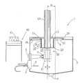
도 1은 본 발명의 세정 챔버와 수송 기구를 포함한 세정 플랜트의 도식도.
도 2는 본 발명의 챔버 입구의 밀봉 구조의 일례를 보인 예시도.
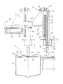
도 3은 본 발명의 세정 챔버와 수송 기구를 포함하고 수송 기구가 선반 위에 놓였을 때의 세정 플랜트의 예시도.
도 4는 본 발명의 세정 챔버와 수송 기구를 포함한 세정 플랜트의 측면도.
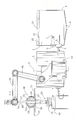
도 5는 본 발명의 산업용 로봇을 수송 기구로 사용한 세정 플랜트의 예시도.
도 6은 본 발명의 산업용 로봇을 수송 기구로 사용하고 세정 대상물을 이동하는 세정 플랜트의 예시도.
도 7은 본 발명의 산업용 로봇을 수송 기구로 사용하고 세정 대상물을 세정하는 세정 플랜트의 예시도.
도 8은 본 발명의 산업용 로봇을 수송 기구로 사용하고 세정 대상물을 또 다른 작동 위치에서 세정하는 세정 플랜트의 예시도.
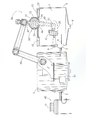
도 9는 도 5 내지 도 8에 따른 실시의 변형예를 보인 예시도.
도 10은 도 9의 세정 플랜트를 자세하게 나타낸 예시도.
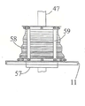
도 11은 리프팅 아암의 자동 조심 위치를 자세하게 나타낸 예시도.1 is a schematic view of a cleaning plant including a cleaning chamber and a transport mechanism of the present invention.
Figure 2 is an exemplary view showing an example of the sealing structure of the chamber inlet of the present invention.
3 is an illustration of a cleaning plant that includes the cleaning chamber and the transport mechanism of the present invention when the transport mechanism is placed on a shelf.
4 is a side view of a cleaning plant including the cleaning chamber and the transport mechanism of the present invention.
5 is an exemplary view of a cleaning plant using the industrial robot of the present invention as a transport mechanism.
6 is an exemplary view of a cleaning plant using the industrial robot of the present invention as a transport mechanism and moving a cleaning object.
7 is an illustration of a cleaning plant for cleaning a cleaning object using the industrial robot of the present invention as a transport mechanism.
8 is an exemplary view of a cleaning plant using the industrial robot of the present invention as a transport mechanism and cleaning the cleaning object in another operating position.
9 is an exemplary view showing a modification of the embodiment according to FIGS. 5 to 8.
10 is an exemplary view showing in detail the cleaning plant of FIG.
11 is an exemplary view showing in detail the self-aligning position of the lifting arm.
다음은 본 발명 세정 플랜트의 실시예를 개시한다. 첫 번째 실시예는 도 1 내지 도 4에 도시되어 있고, 두 번째 실시예는 도 5 내지 도 8에 도시되어 있다. 도 9 내지 도 11은 도 5 내지 도 8에 따른 실시예의 변형이 도시되어 있다. 플랜트의 동일한 부분은 동일한 참조 번호로 제공된다. The following discloses an embodiment of the cleaning plant of the present invention. The first embodiment is shown in Figs. 1 to 4, and the second embodiment is shown in Figs. 9 to 11 show a variant of the embodiment according to FIGS. 5 to 8. The same parts of the plant are given the same reference numbers.
도 1 내지 도 4에 도시된 세정 플랜트는 한 개의 세정챔버(1)를 구비하고, 도 5 내지 도 8에 도시된 세정 플랜트는 복수의 세정챔버(1)를 구비하며, 각 플랜트는 수송 기구(2)를 구비한다. 상기 세정 챔버(1)는 사용된 세정액을 배출하는 하단 배수관(4)이 구비된 판금제 하우징(3)을 포함하여 구성된다. 처리물질을 분사하는 배출수단(5)(6)은 세정챔버(1)의 외주면에 설치되고, 세정 챔버(1) 내부로 돌출된다. 각 수단은 회전하여 흩뿌리거나 스프레이하거나 또는 배출하는 노즐(7)로 구성하거나 높은 압력으로 스프레이하기 위하여 랜스(8)로 구성할 수도 있다. 중앙입구(9)는 판금제 하우징(3)의 상부 정면 벽(10)에 형성되어 세정챔버(1) 배수관(4)의 반대측에 위치한다. 이때, 판금제 하우징(3)은 커버(11)에 의해 폐쇄될 수 있다. 실시예에는 중앙입구(9)가 원형으로 형성되었지만, 커버(11)와 중앙입구(9)를 사각형이나 정사각형으로 형성하는 것도 가능하다. 중앙입구(9)의 주변은 외부로 돌출되어 형성된 원형의 칼라 웹(Collar web, 12)이 구비되어 있다. 상기 커버(11)는 리프트 암(15)의 샤프트(14)를 들어올리기 위한 중앙구멍(13)을 포함한다. 도 1 내지 도 3에는 슬라이드가 가능한 다단식 밀폐 구조, 즉 텔레스코픽 구조를 형성하기 위한 가이드(18)가 도시되어있다. 상기 커버(11)는 칼라와 유사한 형태의 실린더형 연장관(19)을 내부에 구비하고 있고, 리프팅아암(15)은 실린더 칼라(21)에 구비되어 그 끝이 함께 그리핑툴(Gripping tool, 20)에 연결된다. 상기 연장관(19)과 칼라(21)은 텔레스코픽 구조로 설치되어 서로에 대해 슬라이드가 될 수 있도록 구성된다. 상기 칼라(21)는 바닥부(22)에 의해 리프팅아암(15)의 전단과도 연결되고, 동조기구(23)로서 수행되는 플랜지를 구비한다. 만약 리프팅아암(15)이 상측으로 이동하면, 상기 동조기구(23)가 특정 상승 높이로부터 시작하여 커버(11)와 연결되게 되고, 함께 상측으로 이동된다. 반대의 경우로는, 커버(11)는 정면 벽(10) 또는 중간 커버(24)에 형성된다. 도 4에 도시된 바와 같이 커버(11)는 가이드(16)에 연결되어 있다. 상기 가이드(16)는 중앙 구멍(13)의 주변 지역에 형성된 부시(17)를 구비하고, 커버(11)는 샤프트(14)를 따라 슬라이드 가능하게 연결된다. The cleaning plant shown in FIGS. 1 to 4 has one
도 2에서 도시된 바와 같이, 입구(25)를 구비한 헐거운 중간 커버(24)는 정면 벽(10)에 설치된다. 상기 입구(25)의 지름은 정면 벽(10)에 형성된 중앙입구(9)의 지름에 상응하거나 약간 더 작을 수 있다. 중간 커버(24)의 지름은 중앙입구(9)의 지름보다 크고, 지름의 외주면에는 중간 커버(24)가 정면 벽(10)에 설치될 수 있도록 하는 칼라(26)를 구비한다. 상기 중간 커버(24)는 중앙입구(9) 주변에 형성되고 외부를 향하도록 형성된 웹(27)이 구비된다. 그리고 중간 커버(24)와 중앙 입구(9)의 지름의 차이로 인해 디멘션(B)가 형성되며, 이로 인해 중간 커버(24)가 정면 벽(10) 위에서 어느 방향으로나 이동하는 것이 가능하다. 중간 커버(24)가 정면 벽(10) 위에서 이동할 수 있는 반경은 칼라 웹(12)과 칼라(26)에 의해 제한된다. 즉, 칼라 웹(12)과 칼라(26)가 중간 커버(24)를 정지하게 하는 수단으로 사용되는 것이다. As shown in FIG. 2, a loose
도 1에 도시된 바와 같이, 리프팅기구(28)의 리프팅아암(15)은 세정챔버(1) 내부로 돌출 삽입된다. 그리고 그리핑툴(20)은 리프팅아암(15)의 단부에 형성되어 세정 대상물인 (G)를 집는다. 그리고 커버(11)의 외측 단부에는 원형의 실링 웹(29)이 구비되고, 상기 커버(11)는 중간 커버(24)와 함께 이동한다. 이는, 실링 웹(29) 내로 대략 동일한 갭을 가진 중간 커버(24)의 웹(27)이 삽입되어, 리프팅 아암(15)이 중앙 입구(9)를 통해 하부로 이동하면, 실링 웹(29)이 중간 커버(24) 위에 놓여 짐으로써 자동적으로 실질적인 연결이 형성된다. As shown in FIG. 1, the lifting
도 1에 도시된 바와 같이 리프팅아암(15)이 위치할 때, 커버(11)는 이동기구(2) 또는 리프팅아암(15)이 전후로 이동하는 것에 따라 중간 커버(24)를 동반 이동시킨다. 이때, 중간 커버(24)의 실링 웹(29)과 웹(27)은 동조 기구로서 작동한다. 전후 이동하는 경우 실질적인 이동 경로는 상술한 커버(11)의 움직임과 같은 디멘션"B”에 상응할 것이다. 본 실시예에는 커버(11)(24)와 중앙입구(9)(25)가 모두 원형으로 설계되었다. When the lifting
도 2에는 변형된 실링 구조가 간단하게 도시되어 있다. 본 실시예는 중앙 커버(24)를 구비하지 않기 때문에 커버(11)가 정면 벽(10) 위에 위치한 실링 웹(29)에 의해 지지된다. 이때 리프팅아암(15)은 세정챔버(1)의 중앙으로부터 이동되어져서 노즐(7)의 방향인 좌측으로 옮겨져 갔음을 발견할 수 있다. 2 shows a simplified sealing structure. Since this embodiment does not have a
도 1 내지 도 4에 도시된 바와 같이, 리프팅아암(15)은 가이드(30)에 수직으로 형성된 기둥으로 형성되며 리프팅아암(15)의 상단부와 드라이브 체인(33)의 락(Lock, 32)을 연결하는 것에 의해 이동하는 것이 가능하다. 드라이브 체인(33)은 두 개의 피니언(34)(35)에 의해 움직이고, 이 중 제 1 피니언(32)는 모터(36)에 의해 작동한다. 체인 전동(31)은 트롤리(38)에 수용되거나 트롤리(38)에 장착된 캐리지(41)를 수용하는 콘솔(37)에 부착되도록 한다. 상기 트롤리(38)는 가이드 레일(39) 위를 이동하고, 세정 대상 물질인 “G”를 이동시키도록 선반(40) 위에 있는 리프팅아암(15)을 세정챔버(1)의 중앙입구(9) 위로 이동하는 것이 가능하다. 상기 수직 이동은 리프팅아암(15)에 의해 수행된다. 그리고 세정 대상 물질인 “G”는 그리핑툴(20)에 의해 선반(40)에 수납되고, 리프팅아암(15)에 의해 상측 이동되며, 세정챔버(1) 내부로 하측 이동한다. 세정 챔버(1) 내부에서 작동된 상태의 리프팅 암(15)은 촉륜(38) 또는 캐리지(41) 와 함께 전후로 움직인다. 따라서 세정 대상 물질인 “G”를 분사, 스프레이, 분출하는 노즐(7)(8)의 주변으로 이동시킬 수 있는 것이다. 상기 커버(11)은 중간 커버(24)와 함께 이동하면서 중앙입구(9)를 닫는다. 상기 리프팅아암(15)은 세정챔버(1) 내에 위치할 때뿐만 아니라 세정될 때에도 수직 방향으로 상하 이동하도록 조정하는 것이 가능하다. 따라서 세정 대상물질인 “G”의 모든 부분이 한 쪽으로도 도달할 수 있게 한다. 더욱 바람직하게는, 그리핑툴(20)을 구비한 리프팅아암(15)은 종축 주변으로 회전 가능하도록 장착될 수 있다. 이로 인해 그리핑툴(20)이 회전할 수 있어서 세정 대상 물질의 모든 주변부가 세정될 수 있는 것이다. 또한 바람직하게는, 모터(43)에 의해 회전하는 그리핑툴(20)의 구동축(42)은 리프팅아암(15)의 타측 단부에 구비되고, 상기 리프팅 암(15)의 전체를 통과하여 장착될 수 있다. As shown in FIGS. 1 to 4, the lifting
수송기구(2)의 유연성을 향상하기 위하여, 캐리지(41)는 트롤리(38)의 레일(44)에 설치된다. 상기 가이드 레일(39)은 다수의 세정 챔버(1)를 따라 선반(40)까지 연결된다. 이때, 구성을 다수의 세정챔버(1)를 원호 모양으로 배치하고 선반(40)을 두 개의 인접한 세정 챔버(1) 사이에 삽입함으로써, 원형의 구조를 가지도록 할 수 있다. 따라서 때묻은 세정 대상물 "G”가 선반(40)에서 옮겨져서 첫 번째 처리 과정, 예를 들어 세정 과정이 이루어지는 첫 번째 세정 챔버로 들어간다. 그리고 마지막 세정 챔버(1)에서는 마지막 처리 과정, 예를 들어 건조 과정이 수행되고, 그 곳에서 세정된 물질인 “G”가 선반(40)으로 이동되어 외부로 배출된다. 만약 캐리지(41)가 트롤리(38) 이동방향의 열십자방향으로 위치한다면, 그리핑툴(20)를 구비한 리프팅아암(15)은 상기 트롤리(38)의 이동방향과 독립적으로 이동하게 할 수 있다. 이러한 구성으로 인하여, 세정 챔버(1)가 불규칙하게 배열되더라도 선반(40)에서 떨어진 거리에서 3-좌표에서 작동할 수 있게 된다. 가장 간단한 예를 들자면, 선반(40)은 예를 들면,원점으로서, 일렬로 정렬된 세정 챔버(1)와 일정거리를 두어 배치된다. 그리고 상기 선반(40)은 컨베이어 벨트에서 세정 대상물인 “G”를 로딩한다. 그리고 그리핑툴(20)을 구비하는 리프팅아암(15)이 세정 대상 물질인 “G”를 집고, 세정 챔버(1)의 높이 이상으로 수직 상부 이동한 뒤, 트롤리(38)가 X좌표에 대하여 첫 번째 세정 챔버(1)를 조정하고, 캐리지(41)는 세정 대상 물질인 “G”를 수반한 리프팅아암(15)을 Y좌표에 대하여 이동시켜서, 세정챔버(1) 내의 중앙입구(9) 또는 다른 입구(25)에 도달하도록 이동시킨다. 그리고 상기 리프팅아암(15)은 세정 대상 물질인 “G”과 함께 그리핑툴(20)을 하측으로 이동시켜 중앙입구(25)(9)를 통과하게 한 뒤 처리과정 동안 그 상태를 유지한다. 이러한 위치로 인하여, 캐리지(41), 트롤리(38), 리프팅아암(15)의 이동 및 세정 위치가 상호 조정되어 개시되도록 할 수 있다In order to improve the flexibility of the
도 1은 수송 기구(2)가 작동되는 위치가 도시되어 있다. 도 3을 통하여는 세정 대상 물질 “G”가 선반(40) 위에 놓여졌을 때 수송 기구(2)는 설정되는 위치를 알 수 있다. 커버(11)와 리프팅 암(15)은 서로 연결된 상태가 도시된다. 도 4에 의하면, 세정 플랜트의 측면이 도시되고, 축륜(38)의 이동 방향에 대하여 직각 방향으로 리프팅 암(15)이 이동하는 것이 캐리지(41)와 함께 이루어 지고 있음을 알 수 있다. 1 shows the position in which the
도5 내지 도8과 도9 내지 도11은 수송 기구(2)로 다수의 축(axes)으로 조종이 가능한 조작기 아암(46)을 구비한 산업용 로봇(45)과 자유단에 그리핑툴(20)을 구비한 리프팅 아암(47)을 포함하는 세정 플랜트가 도시되어 있다. 커버(11)는 리프팅 아암(47)의 샤프트(49)를 따라 중앙 구멍(48)에서 움직일 수 있도록 가이드된다. 상기 커버(11)와 리프팅 아암(47)은 자동 조심 베어링(self-aligning bearing, 50) 형태로 결합 되어져서, 커버(11)가 자유롭게 걸쳐져서 흔들리는 것이 가능하도록 구성된다. 상기 자동 조심 베어링(50)은 도 5 내지 도 8에 도시된 바와 같이 볼 헤드(52)와 볼 소켓(53)을 구비하는 볼 소켓 조인트(51)의 형상으로 형성된다. 상기 볼 헤드(52)는 리프팅 아암(47)의 샤프트(49) 위의 가이드에서 이동 가능하게 고정되고, 볼 소켓(53)은 중앙 구멍(48)내 주변부의 커버(11) 위에 위치한다. 상기 리프팅 아암(47) 단부에 설치된 동조 기구(55)는 상기 커버(11)가 리프팅 아암(47)에 동조하여 이동하는 것이 정지할 수 있도록 형성된다. 그리고 상기 리프팅 아암(47)이 하측으로 이동시에 세정 챔버(1)과 커버(11)가 일렬로 위치하여 커버(11)가 닫힐 수 있도록 상기 커버(11)는 세정 챔버(1) 위에 위치한다. 작동 중에는, 그리핑툴(20)은 리프팅 아암(47)과 같이 가이드(54) 내에서 상하로 움직일 수도 있고, 또는 그리핑툴(20)은 조작기 아암(46)과 같이 자동 조정 움직임이 있는 자동 조심 베어링(50) 내로 움직일 수도 있다. 이러한 이동을 수행하는 또 다른 방법은, 커버(11)가 중앙입구(9)의 주변부의 지지 표면에 의해 움직인다는 점을 이용하는 것이다. 이로 인해, 그리핑툴(20)의 전후 움직임이 실행될 수 있다. 이와 같이, 세정 챔버의 다양한 측면에서 세정 대상 물질인 “G”를 최적의 상태로 조정하고 일렬로 배열하는 것이 가능하다. 게다가, 그리핑툴(20)을 회전시키고 피보팅하는 것은 도 7에서 도시된 것 같이 리프팅 아암(47)의 샤프트(56)에 의해 가능하다. 도 7은 세정 챔버(1)의 우측 주변부로 커버(11)가 이동된 것이 도시되어 있다. 그리고 도 8은 세정 챔버(1)의 좌측 주변부로 커버(11)가 이동된 것이 도시되어 있다. 5-8 and 9-11 show an
도 9 내지 도 11에 의하면, 도시 5 내지 8에 도시되어 다양하게 변형된 형태의 세정 플랜트가 도시되어 있다. 이 중, 중요한 상이점을 보이는 부분은 자동 조심 베어링(50)의 구조이다. 도 5 내지 도 8에서 도시된 플랜트의 다른 부분들은 도 9 내지 도 11에도 동일하게 적용되어, 상술한 동일한 설명이 적용될 수 있다. 자동 조심 베어링(50)은 세정 챔버(1) 내에서 그리핑툴(20)을 구비한 리프팅 아암(47)의 움직임이 다양한 방향으로 이루어지도록 한다. 이는, 커버(11)와 리프팅 암(47) 사이에 별도의 회전하는 조인트나 힌지를 형성하지 않고도 가능하다. 세정 챔버(1) 내에서 처리 과정이 수행될 때, 즉, 커버(11)가 닫힌 상태일 때, 리프팅 암(47)의 자동 일렬 배치 움직임(self-aligning movement)은 가이드 유닛(57)에 의해 이루어진다. 상기 가이드 유닛(57)은 갭(60)을 통해 커버(11)의 중앙 구멍(48) 안으로 삽입된다. 이 갭(60)은 가이드 유닛(57)이 수평면에 대해 일정한 각도로 경사지더라도 커버(11)와 물리적인 잼(jamming)현상이 발생하지 않을 만큼 충분한 크기로 형성된다. 또한, 상기 갭(60)은 세정 챔버(1)의 정면 벽(10) 상에서 커버(11)의 수평 변위가 리프팅 아암(47)의 수평 변위에 반응할 수 있도록 충분히 작게 형성되기도 한다. 그뿐만 아니라, 가이드 유닛(57)은 길쭉한 형태로 형성되어, 리프팅 아암(47)이 상승하는 전체 과정을 구멍(48) 내에서 인도할 수 있게 한다. 9 to 11, there are shown cleaning plants of various modifications as shown in FIGS. 5 to 8. Among these, the part showing an important difference is the structure of the self-aligning
리프팅 아암(47)은 가이드 유닛(57)을 통과하고, 접속부(61)에 의해 리프팅 암(47)의 샤프트(47)에 견고하게 고정된다. 리프팅 아암(47)과 가이드 유닛(57)은 접속부(61)와 함께 하나의 구조를 형성한다. 단면이 원형이나 사각형인 실린더 또는 오픈-사이드 케이지 등이 가이드 유닛(57)으로 사용될 수 있다. 그리고 갭(60)을 밀봉하기 위하여, 신축성있는 실링 유닛(58)이 방수소재(liquid-tight material)로 만들어져 벨로우(bellows)나 슬리브(sleeve)로 형성되어, 커버(11)와 가이드 유닛(57) 사이에 설치되며, 커버(11)의 플랜지(미도시)의 일측면과 가이드 유닛(57)의 상측 주변부의 타측 단면에 의해 부착된다. 세정 챔버(1)를 청소 시에는 리프팅 암(47)의 움직임을 이용하여 아코디언 악기처럼 실링 유닛(58)에 압력을 가한 뒤 분리해낼 수 있다. 이동 과정 중에 실링 유닛(58)에 적재된 것들을 감소하기 위하여, 가이드 유닛(57) 또는 리프팅 아아암(47)에서 커버(11)를 떼어내도록 운반 끈(59)을 사용하여 커버(11)를 지지하도록 한다.The lifting
1: 세정챔버 2: 수송 기구
3: 판금제 하우징 4: 배수관
5: 배출수단 6: 배출수단
7: 노즐 8: 랜스
9: 중앙 입구 10: 정면 벽 (front wall)
11: 커버(cover) 12: 칼라 웹(collar web)
13: 커버 구멍 14: 샤프트
15: 리프팅 아암 16: 가이드
17: 부시(Bush) 18: 가이드
19: 연장부 20: 그리핑툴 (gripping tool)
21: 칼라(collar) 22: 바닥부(bottom)
23: 동조 기구 (entrainment mechanism) 24: 중간 커버
25: 중간 커버 입구 26: 칼라
27: 웹(web) 28: 리프팅 기구
29: 실링 웹 30: 리프팅 아암의 가이드
31: 체인 전동 32: 락(Lock)
33: 구동 체인 34: 제 1 피니언
35: 제 2 피니언 36: 모터
37: 콘솔 38: 트롤리
39: 가이드 레일 40: 선반
41: 캐리지 42: 구동축
43: 리프팅 암의 모터 44: 레일
45: 로봇 46: 조작기 아암 (manipulator arm)
47: 리프팅 아암 48: 중앙 구멍
49: 샤프트 50: 자동 조심 베어링
51: 볼 소켓 조인트 52: 볼 헤드
53: 볼 소켓 54: 볼 소켓 조인트의 가이드
55: 동조 기구 56: 샤프트
57: 가이드 유닛 58: 실링 유닛
59: 운반 끈 60: 갭
61: 접속부1: cleaning chamber 2: transport mechanism
3: sheet metal housing 4: drain pipe
5: discharge means 6: discharge means
7: Nozzle 8: Lance
9: central entrance 10: front wall
11: cover 12: collar web
13: cover hole 14: shaft
15: Lifting Arm 16: Guide
17: Bush 18: Guide
19: extension 20: gripping tool
21: collar 22: bottom
23: Entrainment mechanism 24: Intermediate cover
25: middle cover opening 26: collar
27: web 28: lifting mechanism
29: sealing web 30: lifting arm guide
31: Chain movement 32: Lock
33: drive chain 34: first pinion
35: second pinion 36: motor
37: console 38: trolley
39: guide rail 40: shelf
41: carriage 42: drive shaft
43: motor of lifting arm 44: rail
45: robot 46: manipulator arm
47: lifting arm 48: center hole
49: shaft 50: self-aligning bearing
51: ball socket joint 52: ball head
53: ball socket 54: guide of ball socket joint
55: tuning mechanism 56: shaft
57: guide unit 58: sealing unit
59: carrying string 60: gap
61: connection
Claims (21)
상기 수송 기구(2)는 세정 대상 물질(G)를 위한 그리핑툴(20)을 구비하고 세정 챔버(1) 내부로의 이송이 가능한 리프팅 기구(28)를 구비하고, 상기 그리핑툴(20)은 커버(11)에 의해서 밀폐되는 것이 가능한 세정 챔버(1)의 입구(9)를 통하여 안내되어,
상기 리프팅 기구(28)와 상기 커버(11)는 하나의 구조 단위를 이루는 산업용 세척 플랜트에 있어서;
상기 커버(11)는 리프팅 기구(28)의 리프팅 아암(15)의 샤프트(14)를 따라서 구멍(13)에서 가이드(18)(16)에 이동가능하도록 지지되고,
세정 챔버(1)를 열기 위한 리프팅 아암(15)의 상향 이동 및 세정 챔버(1)를 달기 위한 리프팅 아암(15)의 하향 이동에서 상기 세정 챔버(1)상의 커버(11)를 멈추는 동조 기구(23)가 구비되어,
커버(11)가 닫힌 상태에서 세정 챔버(1)내의 그리핑툴(20)의 상하 이동이 상기 리프팅 아암(15)에 의하여 제어됨을 특징으로 하는 산업용 세척 플랜트.One or more cleaning chambers and a transport mechanism (2) actuated, rotated and pivoted for loading unloading,
The transport mechanism 2 has a gripping tool 20 for cleaning the substance G and a lifting mechanism 28 which can be transported into the cleaning chamber 1. ) Is guided through the inlet 9 of the cleaning chamber 1, which can be sealed by the cover 11,
The lifting mechanism 28 and the cover 11 in an industrial cleaning plant forming one structural unit;
The cover 11 is supported to be movable from the hole 13 to the guide 18, 16 along the shaft 14 of the lifting arm 15 of the lifting mechanism 28,
A tuning mechanism for stopping the cover 11 on the cleaning chamber 1 in the upward movement of the lifting arm 15 for opening the cleaning chamber 1 and in the downward movement of the lifting arm 15 for attaching the cleaning chamber 1 ( 23) is provided,
Industrial cleaning plant, characterized in that the up and down movement of the gripping tool (20) in the cleaning chamber (1) with the cover (11) closed is controlled by the lifting arm (15).
상기 수송 기구(2)는 세정 대상 물질(G)를 위한 그리핑툴(20)을 구비하고 세정 챔버(1) 내부로의 이송이 가능한 리프팅 기구(28)를 구비하고, 상기 그리핑툴(20)은 커버(11)에 의해서 밀폐되는 것이 가능한 세정 챔버(1)의 입구(9)를 통하여 안내되어,
상기 리프팅 기구(28)와 상기 커버(11)는 하나의 구조 단위를 이루는 산업용 세척 플랜트에 있어서;
상기 리프팅 기구(28)는 축을 따라 제어 가능한 조작기 아암(46)과 그리핑툴(20)을 가진 리프팅 아암(47)을 구비하고,
상기 커버(11)는 구멍(13)을 통해 리프팅 아암(15)의 샤프트(14)를 따라 이동 가능하게 안내되고,
상기 커버(11)와 리프팅 아암(47)은 자동 조심 베어링(50)을 통해 연결이 형성되고,
상기 리프팅 아암(47)을 사용하기 위한 축 가이드(54)를 구비하고,
동조 기구(55)를 포함하여 상기 동조기구(55)는 상기 리프팅 아암(47)이 상향 이동할 때 커버(11)를 함께 동조하게 하고 상기 커버(11)의 정지를 형성하고,
세정 챔버(1)를 닫기 위하여 리프팅 아암(47)이 하향 이동할 때 커버(11)가 세정 챔버 위에 위치할 수 있도록 하여,
세정 챔버(1) 내에서 가이드(54)에서의 리프팅 아암(47)의 직선 움직임, 또는 자동 조정 베어링(50) 내의 리프팅 아암(47)의 자동 조정 움직임은 상기 조작기 아암(46)에 의해 제어 가능한 것을 특징으로 하는 산업용 세척 플랜트.One or more cleaning chambers, and a transport mechanism (2) that is pivoted and operated for loading and unloading,
The transport mechanism 2 has a gripping tool 20 for cleaning the substance G and a lifting mechanism 28 which can be transported into the cleaning chamber 1. ) Is guided through the inlet 9 of the cleaning chamber 1, which can be sealed by the cover 11,
The lifting mechanism 28 and the cover 11 in an industrial cleaning plant forming one structural unit;
The lifting mechanism 28 has a lifting arm 47 having a manipulator arm 46 and a gripping tool 20 which are controllable along an axis,
The cover 11 is movably guided along the shaft 14 of the lifting arm 15 via a hole 13,
The cover 11 and the lifting arm 47 are connected via a self-aligning bearing 50,
With a shaft guide 54 for using the lifting arm 47,
The tuning mechanism 55, including the tuning mechanism 55, causes the cover 11 to tune together when the lifting arm 47 moves upwards and forms a stop of the cover 11,
The cover 11 can be positioned above the cleaning chamber when the lifting arm 47 moves downward to close the cleaning chamber 1,
The linear movement of the lifting arm 47 in the guide 54 in the cleaning chamber 1 or the automatic adjustment movement of the lifting arm 47 in the automatic adjustment bearing 50 is controllable by the manipulator arm 46. Industrial washing plant, characterized in that.
상기 수송 기구(2)는 산업용 로봇(45)인 것을 특징으로 하는 산업용 세척 플랜트.3. The method of claim 2,
Industrial transport plant, characterized in that the transport mechanism (2) is an industrial robot (45).
상기 리프팅 아암(47)의 샤프트(49) 상의 자동 조심 베어링(50)을 위해 커버(11)의 중앙 구멍(48) 안에 갭(60)을 가지고 삽입된 가이드 유닛(57)이 고정되고, 시스나 슬리브 같은 플렉시블 실링 유닛(58)이 일측은 커버(11)에 타측은 가이드 유닛(57) 또는 리프팅 아암(47)에 연결되고, 가이드 유닛(57)을 둘러싼 형태로 제공되는 것을 특징으로 하는 산업용 세척 플랜트. The method according to claim 2 or 3,
For the self-aligning bearing 50 on the shaft 49 of the lifting arm 47 a guide unit 57 inserted with a gap 60 in the central hole 48 of the cover 11 is fixed, Industrial cleaning, characterized in that the flexible sealing unit 58, such as a sleeve, is connected to the guide unit 57 or the lifting arm 47 on one side to the cover 11, and is provided in a form surrounding the guide unit 57 plant.
상기 커버(11)는 상기 가이드 유닛(57)을 따라 중앙 구멍(48) 안에 지지되는 것을 특징으로 하는 산업용 세척 플랜트.3. The method of claim 2,
Industrial cover, characterized in that the cover (11) is supported in the central hole (48) along the guide unit (57).
상기 커버(11)는 운반 끈(59)에 의해 지지되는 것을 특징으로 하는 산업용 세척 플랜트.6. The method according to any one of claims 2 to 5,
Industrial cover, characterized in that the cover (11) is supported by a carrying strap (59).
상기 실링 유닛(58)은 방수 소재로 구성되는 것을 특징으로 하는 산업용 세척 플랜트.The method of claim 3, wherein
The sealing unit 58 is an industrial cleaning plant, characterized in that consisting of a waterproof material.
상기 자동 조심 베어링(50)은 볼 소켓 조인트(51)의 형태로 구성되고,
상기 볼 소켓 조인트(51)는 리프팅 아암(47) 상의 볼 헤드(52)와 커버(11) 상의 볼 소켓(53)으로 구성된 산업용 세척 플랜트.The method according to claim 2 or 3,
The self-aligning bearing 50 is configured in the form of a ball socket joint 51,
Said ball socket joint (51) consisting of a ball head (52) on a lifting arm (47) and a ball socket (53) on a cover (11).
상기 볼 소켓(53)은 중앙 구멍(48) 주변에 형성되는 것을 특징으로 하는 산업용 세척 플랜트.The method of claim 8,
The ball socket (53) is an industrial cleaning plant, characterized in that formed around the central hole (48).
상기 중앙 입구(9)의 지름은 상기 커버(11)의 지름보다 작고, 리프팅 아암(15)(47)과 함께 밀폐하는 상기 커버(11)는 정면 벽(10) 상에서 움직이는 것이 가능한 것을 특징으로 하는 산업용 세척 플랜트.10. The method according to any one of claims 1 to 9,
The diameter of the central inlet 9 is smaller than the diameter of the cover 11, characterized in that the cover 11 sealing together with the lifting arms 15, 47 is movable on the front wall 10. Industrial washing plant.
상기 가이드(18)는 커버(11)에서 리프팅 아암(15)에 이르는 텔레스코픽 구조 또는 교합식의 지역(region)을 구비하는 것을 특징으로 하는 산업용 세척 플랜트.The method of claim 1,
The guide (18) is characterized in that it has a telescopic structure or occlusal region from the cover (11) to the lifting arm (15).
상기 가이드(18)는,
텔레스코픽한 밀봉 구조를 형성하기 위해, 커버(11) 내부에 칼라 같은 원통형의 연장부(19)를 구비하고, 단부에 그리핑툴(20)을 구비한 리프팅 아암(15)에 원통형의 칼라(21)를 구비하고, 상기 연장부(19)와 칼라(21)는 서로 슬라이딩 할 수 있도록 형성된 것을 특징으로 하는 산업용 세척 플랜트.The method of claim 11,
The guide 18,
To form a telescopic sealing structure, a cylindrical collar 21 is provided on a lifting arm 15 with a collar-like cylindrical extension 19 inside the cover 11 and a gripping tool 20 at the end. ) And the extension part (19) and the collar (21) are formed to slide with each other.
상기 커버(11)와 세정 챔버(1)의 중앙 입구(9)의 주변부에 자리한 지지표면은 상호 열십자 방향으로 이동 가능한 밀봉 구조를 형성하는 것을 특징으로 하는 산업용 세척 플랜트.13. The method according to any one of claims 1 to 12,
An industrial cleaning plant, characterized in that the support surface located at the periphery of the cover (11) and the central inlet (9) of the cleaning chamber (1) forms a sealing structure that is movable in a crosswise direction.
상기 커버(11)는,
중앙 입구(9)의 주변에 위치한 실링 웹(29)에 의해 정면 벽(10)에 지지되는 것을 특징으로 하는 산업용 세척 플랜트.14. The method according to any one of claims 1 to 13,
The cover 11,
Industrial cleaning plant, characterized in that it is supported on the front wall (10) by a sealing web (29) located around the central inlet (9).
상기 세정 챔버(1)의 상기 정면 벽(10) 위에는, 중앙 입구(9)의 주변부 표면 위에서 이동 가능한 중간 커버(24)가 중앙 입구(9)의 주변부 가장자리부에 구비되고,
상기 중간 커버(24)는 세정 챔버(1)의 리프팅 아암(15)(48)이 이동하는 방향에 대하여 커버(11)와 결합되는 것을 특징으로 하는 산업용 세척 플랜트.15. The method according to any one of claims 1 to 14,
On the front wall 10 of the cleaning chamber 1, an intermediate cover 24, which is movable on the peripheral surface of the central inlet 9, is provided at the peripheral edge of the central inlet 9,
The intermediate cover (24) is an industrial cleaning plant, characterized in that it is coupled with the cover (11) with respect to the direction in which the lifting arm (15) (48) of the cleaning chamber (1) moves.
상기 중간 커버(24)의 내부 가장자리에는 상기 커버(11) 방향으로 둥글게 둘러싼 웹(27)을 구비하고, 외부 가장자리에는 정면 벽(10) 방향으로 둥글게 둘러싼 칼라(26)를 구비하는 것을 특징으로 하는 산업용 세척 플랜트.The method of claim 15,
An inner edge of the intermediate cover 24 is provided with a web 27 rounded in the direction of the cover 11 and an outer edge with a collar 26 rounded in the direction of the front wall 10. Industrial washing plant.
상기 중앙 입구(9)의 가장자리는 둥글게 둘러싼 칼라 웹(12)이 형성된 것을 특징으로 하는 산업용 세척 플랜트.17. The method according to any one of claims 1 to 16,
The edge of the central inlet (9) is an industrial cleaning plant, characterized in that the rounded collar web (12) is formed.
상기 수송 기구(2)는 선반(40)과 세정 챔버(1) 사이를 따라 이동하는 트롤리(38)를 구비한 것을 특징으로 하는 산업용 세척 플랜트.The method of claim 1,
The transport mechanism (2) is an industrial cleaning plant, characterized in that it has a trolley (38) that moves between the shelf (40) and the cleaning chamber (1).
리프팅 아암(15)을 상향 이동시키는 캐리지(41)가 이동하는 방향의 열십자 방향으로 형성된 레일(44)이 상기 트롤리(38)에 설치되는 것을 특징으로 하는 산업용 세척 플랜트.19. The method of claim 18,
Industrial trolley (38), characterized in that the trolley (38) is provided with a rail (44) formed in a crisscross direction in the direction in which the carriage (41) for moving the lifting arm (15) upwards.
상기 리프팅 아암(15)은 가이드(30)에 고정된 기둥(column)처럼 수행되고,
상기 기둥은 그리핑툴(20)을 위해 종단 방향으로 연속적인 구동축(42)을 구비하는 것을 특징으로 하는 산업용 세척 플랜트.The method according to any one of claims 1 and 10 to 15,
The lifting arm 15 is performed like a column fixed to the guide 30,
The pillar is characterized in that the industrial cleaning plant, characterized in that it has a continuous drive shaft (42) in the longitudinal direction for the gripping tool (20).
상기 리프팅 아암(15)은, 그 상측 단부에서, 상기 리프팅 암(15)은 락(32)과 함께 체인 전동(31)에 고정되고,
상기 체인 전동(31)은 상측 피니언(34)과 하측 피니언(35) 사이에서 안내되고, 상기 트롤리(38)의 콘솔(37)에 설치되는 것을 특징으로 하는 산업용 세척 플랜트.The method according to any one of claims 1 and 18 to 20,
The lifting arm 15, at its upper end, the lifting arm 15 is fixed to the chain transmission 31 together with the lock 32,
The chain transmission (31) is guided between the upper pinion (34) and the lower pinion (35), industrial washing plant, characterized in that installed in the console (37) of the trolley (38).
Applications Claiming Priority (5)
| Application Number | Priority Date | Filing Date | Title |
|---|---|---|---|
| DE102010051686 | 2010-11-17 | ||
| DE102010051686.4 | 2010-11-17 | ||
| DE102011112692.2A DE102011112692B4 (en) | 2010-11-17 | 2011-09-07 | Industrial cleaning system |
| DE102011112692.2 | 2011-09-07 | ||
| PCT/DE2011/075277 WO2012065607A1 (en) | 2010-11-17 | 2011-11-17 | Industrial cleaning system |
Publications (1)
| Publication Number | Publication Date |
|---|---|
| KR20140027912A true KR20140027912A (en) | 2014-03-07 |
Family
ID=45554408
Family Applications (1)
| Application Number | Title | Priority Date | Filing Date |
|---|---|---|---|
| KR1020137014757A KR20140027912A (en) | 2010-11-17 | 2011-11-17 | Industrial cleaning system |
Country Status (9)
| Country | Link |
|---|---|
| US (1) | US9186708B2 (en) |
| EP (1) | EP2640530B1 (en) |
| JP (1) | JP2013544183A (en) |
| KR (1) | KR20140027912A (en) |
| CN (1) | CN103221154B (en) |
| DE (1) | DE102011112692B4 (en) |
| PL (1) | PL2640530T3 (en) |
| RU (1) | RU2568214C2 (en) |
| WO (1) | WO2012065607A1 (en) |
Families Citing this family (23)
| Publication number | Priority date | Publication date | Assignee | Title |
|---|---|---|---|---|
| DE102014001117A1 (en) | 2014-01-28 | 2015-07-30 | Werner Meissner | Device for a treatment chamber of a cleaning system |
| US9968974B2 (en) * | 2014-02-28 | 2018-05-15 | Fives Cinetic Corporation | Assembly and method for removing a robot from an enclosure |
| DE102014003346A1 (en) | 2014-03-07 | 2015-09-10 | Werner Meissner | Cleaning system for the treatment of workpieces |
| JP6196588B2 (en) * | 2014-07-24 | 2017-09-13 | 株式会社スギノマシン | Feed base device and object drive device |
| JP6227496B2 (en) * | 2014-07-24 | 2017-11-08 | 株式会社スギノマシン | Cleaning device |
| JP6531972B2 (en) * | 2014-11-25 | 2019-06-19 | シブヤマシナリー株式会社 | Cleaning device |
| DE102015207598A1 (en) * | 2015-04-24 | 2016-10-27 | Fraunhofer-Gesellschaft zur Förderung der angewandten Forschung e.V. | An image capture device for automatically creating a computer tomographic image of a component, a method of operating an image capture device, and an in-line component inspection system having an image capture device |
| US9828094B2 (en) * | 2015-07-26 | 2017-11-28 | John B. McMillion | Autonomous cleaning system |
| DE102015011511A1 (en) | 2015-09-03 | 2017-03-09 | Werner Meissner | Device for an industrial cleaning system |
| DE102015011923A1 (en) | 2015-09-12 | 2017-03-16 | Werner Meissner | Cleaning fitting for an industrial cleaning device |
| JP6756539B2 (en) * | 2016-08-04 | 2020-09-16 | オークマ株式会社 | Machine Tools |
| USD865010S1 (en) * | 2017-01-17 | 2019-10-29 | Sugino Machine Limited | Washing machine for machined parts |
| DE102016013245A1 (en) * | 2016-11-08 | 2018-06-07 | Westinghouse Electric Germany Gmbh | Drill for working pipes in radioactive environment |
| DE102018003143A1 (en) | 2018-04-18 | 2019-10-24 | Golo Meißner | Charging station for an industrial cleaning system |
| US11318506B2 (en) * | 2018-08-16 | 2022-05-03 | Taiwan Semiconductor Manufacturing Company Ltd. | Apparatus for cleaning semiconductor equipment |
| DE102018008841A1 (en) | 2018-11-09 | 2020-05-14 | Werner Meissner | Plant and method for cleaning and quality inspection of workpieces |
| DE102018008842A1 (en) | 2018-11-09 | 2020-05-14 | Werner Meissner | Industrial cleaning facility |
| KR102036589B1 (en) * | 2018-11-14 | 2019-10-25 | 주식회사 윈텍오토메이션 | Carbide insert cleaning device of high speed carbide inserts using orthogonal robot |
| US20210146406A1 (en) * | 2019-11-18 | 2021-05-20 | Ford Global Technologies, Llc | Cleaning apparatus for sensor |
| US20220041139A1 (en) * | 2020-08-05 | 2022-02-10 | Ford Global Technologies, Llc | Sensor cleaning apparatus |
| KR20220059756A (en) * | 2020-11-03 | 2022-05-10 | 코닝 인코포레이티드 | Glass sheet cleaning apparatus |
| CN113894109B (en) * | 2021-08-17 | 2023-02-21 | 无锡先导智能装备股份有限公司 | Dust removal mechanism and laser cleaning device |
| CN113894072B (en) * | 2021-09-29 | 2022-10-11 | 东海县红鑫新材料有限公司 | Quartz sand processing equipment and processing method based on circulating preparation mechanism |
Family Cites Families (28)
| Publication number | Priority date | Publication date | Assignee | Title |
|---|---|---|---|---|
| US3603037A (en) * | 1969-04-01 | 1971-09-07 | Carborundum Co | Workpiece-treating system |
| JPS5116464U (en) | 1974-07-24 | 1976-02-06 | ||
| US4038155A (en) * | 1976-04-05 | 1977-07-26 | Purex Corporation Ltd. | Energy saving vapor degreasing apparatus |
| JPS5630964U (en) * | 1979-08-20 | 1981-03-25 | ||
| JPS6212470Y2 (en) * | 1979-10-27 | 1987-03-31 | ||
| DE3242719C2 (en) * | 1981-12-01 | 1986-05-22 | LPW-Reinigungstechnik GmbH, 7024 Filderstadt | Device for the solvent treatment of, in particular, metallic items to be treated |
| JPS58127396U (en) | 1982-02-22 | 1983-08-29 | 株式会社東芝 | Control rod drive mechanism automatic disassembly and cleaning equipment |
| JPS5965792U (en) | 1982-10-22 | 1984-05-02 | ジヤパン・フイ−ルド株式会社 | cleaning equipment |
| SU1282926A1 (en) * | 1985-05-16 | 1987-01-15 | Головное Специализированное Конструкторско-Технологическое Бюро Моечного Оборудования | Installation for cleaning articles |
| SU1558519A1 (en) * | 1987-02-13 | 1990-04-23 | Головное Специализированное Конструкторско-Технологическое Бюро Моечного Оборудования | Installation for cleaning articles |
| US5261715A (en) * | 1988-11-14 | 1993-11-16 | John A. Blatt | Work holder support apparatus |
| US5062758A (en) * | 1989-03-31 | 1991-11-05 | Wentgate Dynaweld, Inc. | Shuttle system for rapidly manipulating a workpiece into and out of an atmospherically controlled chamber for doing work thereon in the chamber |
| US5105932A (en) * | 1990-03-09 | 1992-04-21 | Bryson Iii Charles E | Linear and rotary positioning device |
| US5148714A (en) * | 1990-10-24 | 1992-09-22 | Ag Processing Technology, Inc. | Rotary/linear actuator for closed chamber, and reaction chamber utilizing same |
| DE4125891C2 (en) | 1991-08-05 | 1995-01-19 | Hermann Ziegler | Process for cleaning dirty parts |
| JP2866954B2 (en) | 1992-10-19 | 1999-03-08 | 旭エンジニアリング株式会社 | Automatic tank cleaning device |
| JPH08340077A (en) | 1995-06-12 | 1996-12-24 | Hitachi Cable Ltd | Method for removing solvent |
| JPH0919663A (en) | 1995-07-06 | 1997-01-21 | Kyodo Kumiai Ekoro Clean Plaza | Washing device |
| DE19703310C1 (en) | 1997-01-30 | 1998-04-23 | Meisner Werner | Industrial cleaning plant for surface treatment of workpieces |
| JP2001170576A (en) | 1999-12-20 | 2001-06-26 | Mitsuo Wazawa | Pallet washing apparatus |
| JP2001232320A (en) * | 2000-02-21 | 2001-08-28 | Sugino Mach Ltd | Can body washing apparatus |
| DE10230396B4 (en) | 2002-07-05 | 2010-11-25 | Rösler Oberflächentechnik GmbH | working chamber |
| DE10314181A1 (en) * | 2003-03-28 | 2004-10-14 | Rösler Oberflächentechnik GmbH | working chamber |
| DE102005003093B4 (en) * | 2005-01-22 | 2018-12-13 | Ecoclean Gmbh | purifier |
| DE102005031515B4 (en) * | 2005-07-06 | 2023-06-01 | Werner Meissner | Industrial cleaning plant |
| DE102006026171B4 (en) | 2006-06-06 | 2024-03-28 | Werner Meissner | Device for surface treatment of industrial parts |
| DE102007047934A1 (en) | 2007-12-20 | 2009-06-25 | Moll Maschinenbau Gmbh | Apparatus and method for cleaning workpieces |
| JP5089628B2 (en) | 2009-02-18 | 2012-12-05 | 三菱電機株式会社 | Cleaning device, cleaning method and object to be cleaned |
-
2011
- 2011-09-07 DE DE102011112692.2A patent/DE102011112692B4/en active Active
- 2011-11-17 CN CN201180055379.0A patent/CN103221154B/en active Active
- 2011-11-17 KR KR1020137014757A patent/KR20140027912A/en not_active Application Discontinuation
- 2011-11-17 RU RU2013122924/05A patent/RU2568214C2/en active
- 2011-11-17 US US13/988,129 patent/US9186708B2/en active Active
- 2011-11-17 JP JP2013539139A patent/JP2013544183A/en active Pending
- 2011-11-17 PL PL11813774T patent/PL2640530T3/en unknown
- 2011-11-17 EP EP11813774.4A patent/EP2640530B1/en active Active
- 2011-11-17 WO PCT/DE2011/075277 patent/WO2012065607A1/en active Application Filing
Also Published As
| Publication number | Publication date |
|---|---|
| DE102011112692A1 (en) | 2012-05-24 |
| DE102011112692B4 (en) | 2024-03-28 |
| EP2640530A1 (en) | 2013-09-25 |
| RU2568214C2 (en) | 2015-11-10 |
| CN103221154B (en) | 2016-07-20 |
| CN103221154A (en) | 2013-07-24 |
| RU2013122924A (en) | 2015-01-20 |
| WO2012065607A1 (en) | 2012-05-24 |
| US20130233359A1 (en) | 2013-09-12 |
| JP2013544183A (en) | 2013-12-12 |
| US9186708B2 (en) | 2015-11-17 |
| EP2640530B1 (en) | 2015-04-01 |
| PL2640530T3 (en) | 2015-08-31 |
Similar Documents
| Publication | Publication Date | Title |
|---|---|---|
| KR20140027912A (en) | Industrial cleaning system | |
| CA2595327C (en) | Cleaning plant | |
| US6321760B1 (en) | Industrial cleaning facility | |
| KR102343623B1 (en) | Stations and plants for the surface-treatment of objects | |
| US9027312B2 (en) | Machine and method for treating containers of liquids, and loading device for said containers | |
| KR101244381B1 (en) | Cleaner for wafer container | |
| EP2682197B1 (en) | Machine and method for treating containers of liquids | |
| CN111017487B (en) | Chain type lifting device for cleaning and drying chain type wafer | |
| CN216679261U (en) | Automatic cleaning equipment for semiconductor wafer box | |
| CN109550621B (en) | Automatic flocking production line | |
| EP0060055B1 (en) | Apparatus and method for treating work pieces | |
| KR102009114B1 (en) | Cylinderical type battery of washing machine | |
| JP4950247B2 (en) | Cleaning apparatus, substrate processing system, cleaning method, program, and storage medium | |
| JP2009233596A (en) | Sterilization washing process and sterilization washing device | |
| JP2021023915A (en) | Container washing device | |
| KR20120056485A (en) | Purge systems for a wafer container | |
| JPH044082A (en) | Washing and drying device for moving container | |
| US20140311855A1 (en) | Method for cyclically screening a working chamber opening and a screening device for carrying out the method | |
| JP3226900U (en) | Cleaning equipment | |
| CN113953276A (en) | Quartz tube cleaning and drying device | |
| FR2569168A1 (en) | Semiconductor water handling device |
Legal Events
| Date | Code | Title | Description |
|---|---|---|---|
| WITN | Application deemed withdrawn, e.g. because no request for examination was filed or no examination fee was paid |