KR20140010072A - Motor vehicle door lock - Google Patents
Motor vehicle door lock Download PDFInfo
- Publication number
- KR20140010072A KR20140010072A KR20137024207A KR20137024207A KR20140010072A KR 20140010072 A KR20140010072 A KR 20140010072A KR 20137024207 A KR20137024207 A KR 20137024207A KR 20137024207 A KR20137024207 A KR 20137024207A KR 20140010072 A KR20140010072 A KR 20140010072A
- Authority
- KR
- South Korea
- Prior art keywords
- open
- drive
- closing
- vehicle door
- lever
- Prior art date
Links
Images
Classifications
-
- E—FIXED CONSTRUCTIONS
- E05—LOCKS; KEYS; WINDOW OR DOOR FITTINGS; SAFES
- E05B—LOCKS; ACCESSORIES THEREFOR; HANDCUFFS
- E05B81/00—Power-actuated vehicle locks
- E05B81/02—Power-actuated vehicle locks characterised by the type of actuators used
- E05B81/04—Electrical
-
- E—FIXED CONSTRUCTIONS
- E05—LOCKS; KEYS; WINDOW OR DOOR FITTINGS; SAFES
- E05B—LOCKS; ACCESSORIES THEREFOR; HANDCUFFS
- E05B77/00—Vehicle locks characterised by special functions or purposes
-
- E—FIXED CONSTRUCTIONS
- E05—LOCKS; KEYS; WINDOW OR DOOR FITTINGS; SAFES
- E05B—LOCKS; ACCESSORIES THEREFOR; HANDCUFFS
- E05B81/00—Power-actuated vehicle locks
- E05B81/12—Power-actuated vehicle locks characterised by the function or purpose of the powered actuators
- E05B81/14—Power-actuated vehicle locks characterised by the function or purpose of the powered actuators operating on bolt detents, e.g. for unlatching the bolt
-
- E—FIXED CONSTRUCTIONS
- E05—LOCKS; KEYS; WINDOW OR DOOR FITTINGS; SAFES
- E05B—LOCKS; ACCESSORIES THEREFOR; HANDCUFFS
- E05B81/00—Power-actuated vehicle locks
- E05B81/12—Power-actuated vehicle locks characterised by the function or purpose of the powered actuators
- E05B81/20—Power-actuated vehicle locks characterised by the function or purpose of the powered actuators for assisting final closing or for initiating opening
-
- E—FIXED CONSTRUCTIONS
- E05—LOCKS; KEYS; WINDOW OR DOOR FITTINGS; SAFES
- E05B—LOCKS; ACCESSORIES THEREFOR; HANDCUFFS
- E05B85/00—Details of vehicle locks not provided for in groups E05B77/00 - E05B83/00
- E05B85/20—Bolts or detents
- E05B85/24—Bolts rotating about an axis
- E05B85/243—Bolts rotating about an axis with a bifurcated bolt
-
- E—FIXED CONSTRUCTIONS
- E05—LOCKS; KEYS; WINDOW OR DOOR FITTINGS; SAFES
- E05B—LOCKS; ACCESSORIES THEREFOR; HANDCUFFS
- E05B81/00—Power-actuated vehicle locks
- E05B81/12—Power-actuated vehicle locks characterised by the function or purpose of the powered actuators
- E05B81/20—Power-actuated vehicle locks characterised by the function or purpose of the powered actuators for assisting final closing or for initiating opening
- E05B81/21—Power-actuated vehicle locks characterised by the function or purpose of the powered actuators for assisting final closing or for initiating opening with means preventing or detecting pinching of objects or body parts
-
- Y—GENERAL TAGGING OF NEW TECHNOLOGICAL DEVELOPMENTS; GENERAL TAGGING OF CROSS-SECTIONAL TECHNOLOGIES SPANNING OVER SEVERAL SECTIONS OF THE IPC; TECHNICAL SUBJECTS COVERED BY FORMER USPC CROSS-REFERENCE ART COLLECTIONS [XRACs] AND DIGESTS
- Y10—TECHNICAL SUBJECTS COVERED BY FORMER USPC
- Y10S—TECHNICAL SUBJECTS COVERED BY FORMER USPC CROSS-REFERENCE ART COLLECTIONS [XRACs] AND DIGESTS
- Y10S292/00—Closure fasteners
- Y10S292/23—Vehicle door latches
-
- Y—GENERAL TAGGING OF NEW TECHNOLOGICAL DEVELOPMENTS; GENERAL TAGGING OF CROSS-SECTIONAL TECHNOLOGIES SPANNING OVER SEVERAL SECTIONS OF THE IPC; TECHNICAL SUBJECTS COVERED BY FORMER USPC CROSS-REFERENCE ART COLLECTIONS [XRACs] AND DIGESTS
- Y10—TECHNICAL SUBJECTS COVERED BY FORMER USPC
- Y10T—TECHNICAL SUBJECTS COVERED BY FORMER US CLASSIFICATION
- Y10T292/00—Closure fasteners
- Y10T292/08—Bolts
- Y10T292/1043—Swinging
- Y10T292/1044—Multiple head
- Y10T292/1045—Operating means
- Y10T292/1047—Closure
-
- Y—GENERAL TAGGING OF NEW TECHNOLOGICAL DEVELOPMENTS; GENERAL TAGGING OF CROSS-SECTIONAL TECHNOLOGIES SPANNING OVER SEVERAL SECTIONS OF THE IPC; TECHNICAL SUBJECTS COVERED BY FORMER USPC CROSS-REFERENCE ART COLLECTIONS [XRACs] AND DIGESTS
- Y10—TECHNICAL SUBJECTS COVERED BY FORMER USPC
- Y10T—TECHNICAL SUBJECTS COVERED BY FORMER US CLASSIFICATION
- Y10T292/00—Closure fasteners
- Y10T292/08—Bolts
- Y10T292/1043—Swinging
- Y10T292/1075—Operating means
- Y10T292/108—Lever
-
- Y—GENERAL TAGGING OF NEW TECHNOLOGICAL DEVELOPMENTS; GENERAL TAGGING OF CROSS-SECTIONAL TECHNOLOGIES SPANNING OVER SEVERAL SECTIONS OF THE IPC; TECHNICAL SUBJECTS COVERED BY FORMER USPC CROSS-REFERENCE ART COLLECTIONS [XRACs] AND DIGESTS
- Y10—TECHNICAL SUBJECTS COVERED BY FORMER USPC
- Y10T—TECHNICAL SUBJECTS COVERED BY FORMER US CLASSIFICATION
- Y10T292/00—Closure fasteners
- Y10T292/08—Bolts
- Y10T292/1043—Swinging
- Y10T292/1075—Operating means
- Y10T292/1082—Motor
Abstract
본 발명은 록킹 메커니즘(1, 2)과 닫힘/개방 장치(7 내지 16)를 구비한 차량 도어 록킹 장치에 관한 것이다. 닫힘/개방 장치(7 내지 16)는 적어도 하나의 구동부(7 내지 11 및 13, 14), 적어도 하나의 이송 요소(12, 16) 그리고 구동 폴(16)을 갖는다. 구동부(7 내지 11 및 13, 14)는 록킹 메커니즘(1, 2)을 개방하거나 닫는 기능을 수행하며, 각 이송 요소(12, 15)는 구동 폴(16)에 따라 작용한다. 본 발명에 따르며, 기계적 및/또는 전기적 개방 구동부(7 내지 11) 그리고 기계적 및/또는 전기적 닫힘 구동부(13, 14)는 관련된 개방 이송 레버(12)와 관련된 닫힘 이송 레버(15)를 각각 갖도록 설계된다. 록킹 메커니즘(1, 2)을 위한 개방 기능과 상호 보완적으로, 개방 이송 레버(12)와 함께 개방 구동부(7 내지 11)는 닫힘 이송 레버(15)와 관련하여 닫힘 구동부(13, 14)에 의하여 시작된 닫힘 기능을 방해하도록 설계된다. The present invention relates to a vehicle door locking device having locking mechanisms 1 and 2 and closing / opening devices 7 to 16. The closing / opening device 7-16 has at least one drive 7-11 and 13, 14, at least one conveying element 12, 16 and a drive pawl 16. The drives 7 to 11 and 13 and 14 perform the function of opening or closing the locking mechanisms 1 and 2, with each conveying element 12 and 15 acting in accordance with the drive pawl 16. According to the present invention, the mechanical and / or electrical open drive 7 to 11 and the mechanical and / or electrical closed drive 13, 14 are designed to have a closed transfer lever 15 associated with the associated open transfer lever 12, respectively. do. Complementary with the opening function for the locking mechanism 1, 2, the open drive 7 to 11 together with the open feed lever 12 is connected to the closed drive 13, 14 with respect to the closed feed lever 15. Is designed to interfere with the closing function initiated.
Description
본 발명은 적어도 하나의 구동부, 적어도 하나의 이송 요소 및 구동 폴을 갖는 닫힘/개방 장치 및 록킹 메커니즘을 갖되, 구동부는 이송 요소의 도움으로 구동 폴에 작용하여 록킹 메커니즘을 개방 또는 닫는 차량 도어 록킹 장치에 관한 것이다. The present invention has a closing / opening device and a locking mechanism having at least one drive, at least one transport element and a drive pawl, wherein the drive acts on the drive pawl with the aid of the transport element to open or close the locking mechanism. It is about.
위의 구조를 갖는 차량 도어 록킹 장치가, 예를 들어 독일실용신안 DE 20 2008 015 789 U1에 개시되어 있다. 차량 도어용 닫힘 장치는 일반적으로 예를 들어 차량 도어를 그 중간 록킹 위치에서 그 메인 록킹 위치로 이동시키기 위하여 사용된다. 이 과정 동안, 일반적으로 상당한 반력(counterforce)이 극복되어야 하며, 이 과정 동안에 일반적으로 이 반력은 압축 고무 도어 밀봉재에 의하여 가해진다. 일반적으로 전기적으로 작동하는 닫힘 장치의 도움으로, 닫힘 동작은 특히 편안하고 간단하다.A vehicle door locking device having the above structure is disclosed, for example, in German Utility Model DE 20 2008 015 789 U1. The closing device for a vehicle door is generally used for example to move the vehicle door from its intermediate locking position to its main locking position. During this process, a significant counterforce must generally be overcome, during which the reaction force is generally exerted by the compressed rubber door seal. In general, with the help of an electrically operated closing device, the closing operation is particularly comfortable and simple.
더 나아가, 개방 장치는 일반적으로 록킹 장치의 개방을 보장하는 것으로 알려져 있다. 예를 들어, 이러한 개방 보조 기구가 DE 10 2004 052 599 A1 에 개시되어 있으며, 이는 관련된 DE 20 2008 007 310 U1에 참고적으로 언급되어 있다. 가장 간단한 경우에, 이러한 개방 장치 또는 개방 보조 기구는 전기 구동부를 사용하여 닫혀진 록킹 메커니즘의 로터리 래치로부터 폴을 들어올린다. 그 결과, 로터리 래치는 스프링 그리고 이전에 맞물려진 록킹 볼트의 도움으로 개방될 수 있으며, 따라서 전체 차량 도어를 해제한다. Furthermore, the opening device is generally known to ensure the opening of the locking device. For example, such an opening aid is disclosed in
닫힘 장치 또는 닫힘 보조 기구는 위에서 언급된 DE 20 2008 015 789 U1에 개시된 바와 같이 가끔 소위 비상 중단의 문제점을 갖는다. 그 중에서도 특히, 닫힘 동작이 취소될 때 이러한 비상 중단이 요구된다. 이러한 시나리오의 예가 조작자의 손가락 또는 손이 닫혀질 도어 틈(door gap)으로 들어가는 경우 또는 예를 들어 조작자의 코트가 도어 틈 내에 끼어있는 경우이다. Closing devices or closing aids sometimes have the problem of so-called emergency interruptions as disclosed in DE 20 2008 015 789 U1 mentioned above. In particular, such an emergency stop is required when the closing operation is canceled. An example of such a scenario is when the operator's finger or hand enters a door gap to be closed or when the operator's coat is sandwiched in the door gap, for example.
이 모든 비상 중단의 경우에, 닫힘 작동은 가능하다면 지체 없이 그리고 신뢰할 수 있는 방식으로 중지되어야 하며, 가장 유리한 경우에 도어는 동시에 개방 또는 해제되어야 한다. 이 목적을 위하여 DE 20 2008 015 789는 이송 요소를 갖는 닫힘/개방 장치가 이동을 차단하고 록킹 메커니즘을 작동시키지 않는 절차를 제안하고 있다. 이렇게 하여, 이송 요소와 상호 작용하는 멈춤부는 설명된 블록킹 케이스에서, 발생된 차단력(blocking force)의 일부가 멈춤부로 직접적으로 전달되는 것을 보장한다. 그 결과, 구동 폴과 록킹 메커니즘 사이에서 작용하는 전체 힘은 감소된다. In the case of all these emergency interruptions, the closing operation should be stopped without delay and in a reliable manner if possible, and in the most advantageous case the doors should be opened or released simultaneously. For this purpose DE 20 2008 015 789 proposes a procedure in which a closing / opening device with a transfer element blocks movement and does not activate the locking mechanism. In this way, the stop interacting with the conveying element ensures that in the blocking case described, part of the blocking force generated is transferred directly to the stop. As a result, the overall force acting between the drive pawl and the locking mechanism is reduced.
일반적으로, 구동 폴 또는 닫힘 폴은 로터리 래치에 직접적으로 또는 간접적으로 작용한다. 로터리 래치가 중간 록킹 위치에 있자마자, 로터리 래치가 중간 록킹 위치에서 메인 록킹 위치로 이동되는 방식으로 구동 폴은 모터에 의하여 작동한다. 이는 당연히 단지 한 예이다. In general, the drive pole or the closing pole acts directly or indirectly on the rotary latch. As soon as the rotary latch is in the intermediate locking position, the drive pole is actuated by the motor in such a way that the rotary latch is moved from the intermediate locking position to the main locking position. This is of course only one example.
실질적인 응용에서 닫힘 보조 기구 및 개방 보조 기구를 구비한 또는 구비해야 하는 점점 더 많은 차량 도어 록킹 장치가 사용되고 있다. 이는 한편으로는 높은 편안함의 요구 조건 때문이며, 다른 한편으로는 이미 매우 많은 수의 장치가 생산되었다는 것 때문에 이러한 보조 기구가 점점 더 저렴해져 대량 생산된다는 점에 기인한다. 그러나, 특히 록킹 장치가 또한 닫힘 작동의 비상 중단을 제공하는 옵션을 제공해야만 하는 경우, 이러한 차량 도어 록킹 장치는 비교적 복잡한 디자인을 갖는다. In practical applications more and more vehicle door locking devices are being used with or with the closing and opening aids. This is due, on the one hand, to the requirement of high comfort, and on the other hand, due to the fact that a very large number of devices have already been produced, these assistive devices are becoming cheaper and mass produced. However, such a vehicle door locking device has a relatively complex design, especially if the locking device must also provide the option of providing an emergency interruption of the closing operation.
본 발명의 목적은 이러한 상황을 개선하기 위한 것이다. 본 발명은 전체로서 구성의 복잡함을 줄이고 시너지 효과가 사용될 수 있는 방식으로 이러한 차량 도어 록킹 장치의 추가적인 개발의 기술적 문제점에 기반한다. The object of the present invention is to remedy this situation. The present invention is based on the technical problems of further development of such a vehicle door locking device in such a way that the complexity of the construction as a whole and the synergy effect can be used.
이 기술적 문제를 해결하기 위하여, 본 발명의 차량 도어 록킹 장치는 기계적 및/또는 전기적 개방 구동부 및 기계적 및/또는 전기적 닫힘 구동부가 특징이며, 각 구동부는 관련된 개방 이송 레버와 닫힘 이송 레버를 포함하고, 록킹 메커니즘을 위한 개방 기능을 제공하는 것을 제외하고 개방 이송 레버를 포함하는 개방 구동부는 닫힘 이송 레버와 관련하여 닫힘 구동부에 의하여 시작된 닫힘 기능을 중단시키도록 설계된다. To solve this technical problem, the vehicle door locking device of the present invention is characterized by a mechanical and / or electrically open drive and a mechanical and / or electrically closed drive, each drive including an associated open feed lever and a closed feed lever, Except for providing an opening function for the locking mechanism, an open drive comprising an open transfer lever is designed to stop the closing function initiated by the close drive in relation to the closed transfer lever.
따라서, 본 발명은 개방 기능과 닫힘 기능의 일반적인 기능적 상태가 제공될 수 있도록 개방 구동부와 닫힘 구동부를 사용한다. 개방 기능은 일반적으로 기계적 및/또는 전기적으로 수행된다. 후자의 경우에, 이는 "전기적 개방"으로 언급된다. 다른 한편으로는 닫힘 기능은 일반적으로 단지 전기적이다. Thus, the present invention uses an open drive and a closed drive so that the general functional state of the open and close functions can be provided. The opening function is generally performed mechanically and / or electrically. In the latter case, this is referred to as "electrical opening". On the other hand, the closing function is usually just electrical.
본 발명의 부분으로서, 비상 중단과 관련한 닫힘 기능의 중단은 개방 구동부에 의하여 제공된다. 이는 비상 중단을 생성하기 위하여 본 발명이 부가적인 장치 또는 구동부를 필요로 하지 않고 대신 이 비상 중단은 기존의 개방 구동부에 의하여 생성된다는 것을 의미한다. 본 명세서에서, 닫힘 기능은 기계적으로 그리고/또는 전기적으로 중단될 수 있다. 전자의 경우, 개방 구동부는 기계적인 작동을 발생시켜 닫힘 기능이 중단된다는 것을 보장한다. 후자의 형태에서, 전기적 개방 구동부 "EO"는 닫힘 기능의 중단을 보장한다. As part of the invention, the interruption of the closing function in connection with the emergency interruption is provided by an open drive. This means that the present invention does not require additional devices or drives to create an emergency stop and instead this emergency stop is created by an existing open drive. In the present specification, the closing function may be mechanically and / or electrically interrupted. In the former case, the open drive generates mechanical actuation to ensure that the closing function is stopped. In the latter form, the electrically open drive "EO" ensures the interruption of the closing function.
이렇게 하여, 닫힘 기능의 비상 중단을 위한 경우에 전체적인 복잡도는 감소하고 구동부 간의 시너지 효과가 사용될 수 있다. 이는 제조 비용을 감소시키고 기능적 신뢰도를 증가시킨다. In this way, in case of emergency interruption of the closing function, the overall complexity is reduced and synergies between the drives can be used. This reduces manufacturing costs and increases functional reliability.
이를 세부적으로 달성하기 위하여, 개방 구동부는 개방 이송 레버로 닫힘 폴을 분리하여 닫힘 기능을 중단시킨다. 닫힘 폴은 일반적으로 록킹 메커니즘의 로터리 래치와 맞물린다. 록킹 메커니즘이 어떤 닫힘 위치, 예를 들어 중간 록킹 위치를 취하자마자, 닫힘 구동부는 작동하고 로터리 래치가 현재 닫힘 위치로부터 메인 록킹 위치로 이동하는 것을 닫힘 폴을 통하여 보장한다In order to achieve this in detail, the open drive disengages the closing pawl by means of an open transfer lever. The closing pawl is generally engaged with the rotary latch of the locking mechanism. As soon as the locking mechanism takes any closed position, for example an intermediate locking position, the closing drive is activated and ensures that the rotary latch moves from the current closed position to the main locking position via the closing pole.
이렇게 하여, 본 발명이 어떠한 경우에 차량 도어 록킹 장치와 상호 작용하는 차량 도어가 메인 록킹 위치로 이송되는 것을 보장하고 따라서 사고의 경우에 차량 도어 내부의 모든 안전 장치가 계획된 대로 효과적으로 될 수 있다는 것을 보장함으로써 편안한 닫힘 동작이 제공될 뿐만 아니라 전체적인 신뢰도 또한 증가한다. In this way, the invention ensures that in some cases the vehicle door interacting with the vehicle door locking device is transported to the main locking position and thus that in the event of an accident all safety devices inside the vehicle door can be effectively as planned. This not only provides a comfortable closing action but also increases overall reliability.
예를 들어 걸려진 옷, 손가락, 손 등의 경우의 비상 중단의 부분으로서 설명된 닫힘 작동 또는 닫힘 기능을 중단시키기 위하여, 개방 구동부는 개방 구동부에 배치된 개방 이송 레버의 도움으로 닫힘 폴이 분리되는 것을 보장한다. 분리된 닫힘 폴은 (더 이상) 로터리 래치를 작동시킬 수 없거나 로터리 래치를 닫을 수 없다. 대신, 로터리 래치는 닫힘 폴로부터 해제되고 스프링의 도움으로 그의 개방 위치로 선회될 수 있다. 이전에 결합된 록킹 볼트는 해제된다. 동일한 작동이 관련된 차량 도어를 위하여 적용된다. In order to interrupt the closing action or the closing function described as part of an emergency interruption, for example in the case of hanging clothes, fingers, hands, etc., the open drive is separated with the aid of an open feed lever disposed on the open drive. To ensure that. A separate closing pole cannot (rotate) the rotary latch or close the rotary latch. Instead, the rotary latch can be released from the closing pawl and pivoted to its open position with the aid of the spring. The previously engaged locking bolt is released. The same operation applies for the vehicle door involved.
이를 세부적으로 달성하기 위하여, 장치는 이젝터 레버(ejector lever)를 포함한다. 이젝터 레버는 개방 이송 레버에 의하여 작동되어 닫힘 폴을 꺼낸다. 이 목적을 위하여, 이젝터 레버는 개방 이송 레버와 닫힘 폴 사이에 배치된다. 이젝터 레버가 개방 이송 레버에 의하여 선회되자마자 이젝터 레버는 닫힘 폴이 로터리 래치로부터 들어 올려지는 것을 보장한다. To achieve this in detail, the device comprises an ejector lever. The ejector lever is operated by the open transfer lever to pull out the closing pawl. For this purpose, the ejector lever is arranged between the open transfer lever and the closing pawl. As soon as the ejector lever is pivoted by the open transfer lever, the ejector lever ensures that the closing pawl is lifted from the rotary latch.
본 명세서에서, 본 발명은 또한 이젝터 레버가 닫힘 폴과 동일한 축에 장착되는 구조를 제안한다. 이는 닫힘 이송 레버 상에 장착될 이젝터 레버와 닫힘 폴을 위하여 유리하다. 닫힘 이송 레버는 결국 닫힘 구동부에 연결되어 있다. 닫힘 구동부가 작동하면, 닫힘 이송 레버는 바로 선회된다.In the present specification, the present invention also proposes a structure in which the ejector lever is mounted on the same shaft as the closing pawl. This is advantageous for the ejector lever and the closing pole to be mounted on the closing transfer lever. The closing feed lever is in turn connected to the closing drive. When the closing drive is activated, the closing feed lever is immediately turned.
그 결과, 닫힘 폴 역시 선회되며, 설명한 바와 같이 닫힘 폴은 로터리 래치가 닫히는 것을 보장한다. 닫힘 구동부는 닫힘 이송 레버를 기계적 및/또는 전기적으로 작동시킬 수 있으며, 따라서 설명된 선회를 보장한다. 닫힘 이송 레버는 로터리 래치와 동일 축 상에 장착될 수 있어 전체적으로 콤팩트한 배치를 야기한다. As a result, the closing pole is also pivoted, and as described, the closing pole ensures that the rotary latch is closed. The closed drive can actuate the closed transfer lever mechanically and / or electrically, thus ensuring the described turning. The closed feed lever can be mounted on the same axis as the rotary latches, resulting in a compact arrangement as a whole.
개방 이송 레버는 구동 아암과 작동 아암을 포함하는 적어도 2개의 아암을 포함한다. 구동 아암은 개방 구동부와 상호 작용한다. 한편, 작동 아암은 닫힘 폴의 작동을 제공한다. 이 목적을 위하여, 작동 아암은 이미 위에서 설명된 이젝터 레버에 따라 규칙적으로 작동하며 따라서 닫힘 폴에 작용 또는 닫힘 폴에 직접적으로 작용한다. The open transfer lever includes at least two arms including a drive arm and an actuating arm. The drive arm interacts with the open drive. On the other hand, the actuating arm provides actuation of the closing pole. For this purpose, the actuating arm already works regularly according to the ejector lever described above and thus acts directly on the closing pole or directly on the closing pole.
대부분의 경우, 기계적 그리고 전기적 개방 구동부가 제공된다. 본 명세서에서, 개방 이송 레버는 전기적 개방 구동부의 구동 휠과 상호 작용한다. 이 목적을 위하여, 대부분의 경우 구동 휠은 개방 이송 레버를 작동시키는 캠을 포함한다.In most cases, mechanical and electrical open drives are provided. In the present specification, the open transfer lever interacts with the drive wheel of the electrically open drive. For this purpose, in most cases the drive wheel comprises a cam for operating the open transfer lever.
전기적 개방 구동부의 회전 또는 전기적 개방 구동부에 의하여 작동하는 구동 휠의 회전은 캠에 의하여 개방 이송 레버의 선회 운동으로 변환된다. 개방 이송 레버가 구동 아암 상에서 선회하면, 그 작동 아암은 바로 이젝터 레버가 작동하는 것을 보장한다. 작동하는 이젝터 레버는 이전에 로터리 래치와 맞물려진 닫힘 폴이 로터리 래치로부터 들어 올려지는 것을 보장한다. The rotation of the electrically open drive or the rotation of the drive wheel actuated by the electrically open drive is converted by the cam to the pivoting movement of the open transfer lever. When the open transfer lever pivots on the drive arm, the actuating arm ensures that the ejector lever is actuated. An actuating ejector lever ensures that the closing pawl previously engaged with the rotary latch is lifted from the rotary latch.
설명된 전기적 개방 구동부에 더하여, 기계적 개방 구동부가 개방 이송 레버를 위하여 제공된다. 이 기계적 개방 구동부는 개방 이송 레버의 연결 아암으로 맞물려질 수 있다. 대부분의 경우, 결합 요소가 제공되며, 이 결합 요소는 개방 이송 레버 또는 그 연결 아암을 기계적 개방 구동부에 연결한다. 기계적 개방 구동부는 레버, 감추어진 핸들 등으로 설계될 수 있다. 내부 도어 핸들 및/또는 외부 도어 핸들로의 기계적 연결 또한 가능하다. In addition to the electrically open drive described, a mechanical open drive is provided for the open transfer lever. This mechanical open drive can be engaged with the connecting arm of the open transfer lever. In most cases, a coupling element is provided, which couples the open transfer lever or its connecting arm to the mechanical open drive. Mechanically open drives can be designed with levers, hidden handles, and the like. Mechanical connections to the inner door handle and / or to the outer door handle are also possible.
어떠한 경우, 레버의 작동 또는 각 도어 핸들의 작동 또는 기계적 개방 구동부의 작동은 개방 이송 레버가 다시 선회하는 것을 보장하며, 또한 이러한 방식으로 개방 이송 레버가 그 작동 아암으로 로터리 래치로부터 닫힘 폴을 제거하는 것을 보장한다. 이를 이루기 위하여, 작동 아암은 결국 닫힘 레버를 꺼내는 이젝터 레버에 작용한다. In any case, actuation of the lever or actuation of each door handle or actuation of the mechanically open drive ensures that the open transfer lever pivots again, and in this way also the open feed lever removes the closing pawl from the rotary latch with its operating arm. To ensure that. To accomplish this, the actuating arm acts on the ejector lever which eventually pulls out the closing lever.
이러한 다른 기능적 상태를 세부적으로 제공하기 위하여, 개방 이송 레버는 유리하게는 작동 요소를 포함한다. 이 작동 요소는 개방 기능에서 폴이 록킹 메커니즘의 로터리 래치로부터 들려지는 것을 보장한다. 이는 소위 전기적 개방 "EO" 과정 동안 그리고 기계적 개방 과정 동안에서의 정상적인 기능이다. 개방 이송 레버가 기계적으로/전기적으로 선회(그리고 닫힘 기능이 정지)하자마자, 작동 요소는 폴이 로터리 래치로부터 들려지는 것을 보장한다. 결과적으로, 로터리 래치는 스프링의 도움으로 그 개방 위치로 이동할 수 있으며, 또한 이전에 맞물려진 록킹 볼트를 해제할 수 있다. 록킹 볼트를 수용하는 차량 도어는 개방될 수 있다. In order to provide these other functional details in detail, the open transfer lever advantageously comprises an actuating element. This actuating element ensures that in the open function the pole is lifted from the rotary latch of the locking mechanism. This is a normal function during the so-called electrical opening "EO" process and during the mechanical opening process. As soon as the open transfer lever is mechanically / electrically turned (and the closing function stops), the actuation element ensures that the pawl is lifted from the rotary latch. As a result, the rotary latch can be moved to its open position with the aid of a spring and can also release the previously engaged locking bolt. The vehicle door which receives the locking bolt can be opened.
본 발명의 부분으로서, 작동 요소는 또한 닫힘 기능을 중단하도록 설계된다. 이 목적을 위하여, 작동 요소는 닫힘 폴 및/또는 닫힘 폴의 상부에 있는 이젝터 레버와 상호 작용하여 닫힘 기능을 중단시킨다. As part of the invention, the actuating element is also designed to stop the closing function. For this purpose, the actuation element interacts with the ejector lever on top of the closing pawl and / or the closing pawl to interrupt the closing function.
이 목적을 위하여, 작동 요소는 통상적으로 작동 저널로서 설계된다. 닫힘 기능의 중단 동안에, 이 작동 저널은 이젝트 레버에 작용한다. 이렇게 하여, 닫힘 폴은 로터리 래치로부터 분리된다. 동시에, 작동 요소 또는 작동 저널은 폴이 로터리 래치로부터 들어 올려지는 것을 보장한다. . For this purpose, the actuation element is usually designed as an acting journal. During interruption of the closing function, this working journal acts on the eject lever. In this way, the closing pawl is separated from the rotary latch. At the same time, the actuation element or actuation journal ensures that the pawl is lifted from the rotary latch. .
따라서 폴이 동시에 로터리 래치로부터 들어 올려짐에 따라 닫힘 기능의 중단은 작동 요소 또는 작동 저널의 이중 기능과 기능적으로 관련되어 있다. 다시 말해, 닫힘 폴의 도움으로의 닫힘 작동 동안에, 닫혀진 로터리 래치는 닫혀지고 있는 닫힘 폴로부터 기계적으로 해제될 뿐만 아니라 이 과정 동안에 스프링의 도움을 받는, 로터리 래치의 개방 동작이 지연되지 않는다. 이는 작동 요소 또는 작동 저널이 동시에 "전기적 개방"의 일부로서 폴이 로터리 래치로부터 들어 올려지는 것을 보장하기 때문이다. Thus, the interruption of the closing function is functionally related to the dual function of the actuating element or actuating journal as the pawl is simultaneously lifted out of the rotary latch. In other words, during the closing operation with the help of the closing pawl, the closed rotary latch is not only mechanically released from the closing pawl but also with the aid of the spring during this process, the opening operation of the rotary latch is not delayed. This is because the actuation element or the acting journal at the same time ensures that the pole is lifted from the rotary latch as part of the "electrical opening".
그 결과, 닫힘 기능의 중단 동안에 로터리 래치는 스프링에 의하여 초기 닫힘 위치에서 개방 위치로 자유롭게 선회될 수 있으며, 이전에 맞물려진 차량 도어는 해제된다. As a result, during the interruption of the closing function, the rotary latch can be freely pivoted from the initial closed position to the open position by the spring, and the previously engaged vehicle door is released.
이미 설명된 바와 같이, 개방 구동부는 기계적인 작동을 위하여, 예를 들어 차실(passenger compartment) 내의, 도어 핸들 등을 갖는 부가적인 레버를 포함한다. 또한, 전기적 개방 구동부를 원하는 대로 작동시키기 위하여, 전기 스위칭 요소가 가끔 차실 내에 또는 차실에 인접하게 제공된다. 이 전기적 스위칭 요소는 전형적으로 "전기적 개방" 작동 동안에 효율적으로 사용된다. 동일하게, 전기 스위칭 요소는 필요할 때 닫힘 기능의 설명된 비상 중단을 제공한다. 동일한 것이 레버를 위하여 적용된다. 각 레버와 전기 스위칭 요소는 서로에 대하여 대안으로서 사용될 수 있다. As already explained, the open drive comprises an additional lever with a door handle or the like, for example in a passenger compartment, for mechanical operation. In addition, in order to operate the electrically open drive as desired, electrical switching elements are sometimes provided in or adjacent the compartment. This electrical switching element is typically used efficiently during "electrically open" operation. Equally, the electrical switching element provides the described emergency shutdown of the closing function when necessary. The same applies for the lever. Each lever and electrical switching element can be used as an alternative to each other.
그 결과, 개방 기능뿐만 아니라 닫힘 기능을 구비한 차량 도어 록킹 장치가 제공된다. 전형적으로, 소위 "전기적 개방"이 사용된다. 닫힘 기능의 비상 중단이 요구되는 경우, 본 발명은 공동 작용적으로 개방 구동부를 사용한다. 이 경우, 개방 구동부가 닫힘 장치의 기계적인 연결 체인을 중단시키도록 되어 있다. 상세하게 설명하면, 개방 구동부는 로터리 래치와 맞물려져 있는 닫힘 장치의 닫힘 폴이 이 래치로부터 들려지는 것을 보장한다. As a result, a vehicle door locking device having a closing function as well as a closing function is provided. Typically, so-called "electrical opening" is used. If an emergency stop of the closing function is required, the present invention uses the open drive synergistically. In this case, the open drive is adapted to interrupt the mechanical connection chain of the closing device. In detail, the open drive ensures that the closing pawl of the closing device engaged with the rotary latch is lifted from this latch.
이 과정 동안에 폴이 전형적으로 그리고 동시에 로터리 래치에 대하여 들려 올려짐에 따라, 그 결과 로터리 래치는 기계적인 차단 없이 그리고 스프링에 의하여 선회될 수 있으며, 따라서 이전에 맞물려진 록킹 볼트를 해제한다. 동일한 작용이 록킹 볼트와 상호 작용하는 차량 도어를 위하여 적용된다.이것이 주요 이점이다. As the pawl is lifted against the rotary latch typically and simultaneously during this process, the rotary latch can thus be pivoted without mechanical interruption and by the spring, thus releasing the previously engaged locking bolt. The same action applies for vehicle doors that interact with the locking bolt, which is the main advantage.
본 발명의 해결책은 부가적인 블록킹 폴이 폴을 위하여 사용되는, 로터리 래치와 하나 또는 2개의 폴로 이루어진 록킹 메커니즘을 위하여 또는 다중 폴 록킹 메커니즘을 위하여 동일하게 사용될 수 있다. The solution of the invention can equally be used for a locking mechanism consisting of a rotary latch and one or two poles, or for multiple pole locking mechanisms, in which additional blocking poles are used for the poles.
도 1은 닫힘 과정 동안의 본 발명의 차량 도어 록킹 장치를 도시한 도면.
도 2는 닫힌 상태에서의 록킹 메커니즘을 도시한 도면.
도 3은 닫힘 기능의 중단 (비상 중단) 동안의 도 1에 따른 차량 도어 록킹 장치를 도시한 도면. 1 shows a vehicle door locking device of the invention during a closing process;
2 shows the locking mechanism in the closed state.
3 shows the vehicle door locking device according to FIG. 1 during an interruption of the closing function (emergency interruption).
이하, 본 발명이 단지 한 실시예만을 도시한 첨부된 도면을 참고하여 상세히 설명된다. Hereinafter, the present invention will be described in detail with reference to the accompanying drawings showing only one embodiment.
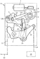
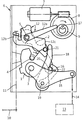
도면들은 로터리 래치(1)와 폴(2)로 이루어진 록킹 메커니즘(1, 2)을 일반적인 방식으로 갖추고 있는 차량 도어 록킹 장치를 도시한다. 로터리 래치(1)가 도 2에 도시된 메인 록킹 위치 또는 닫혀진 위치를 취하자마자, 폴(2)은 로터리 래치(1)에 맞물리고 로터리 래치를 차단한다. 도시된 예에서, 엄격히 말하면 래칭된 연결이 메인 록킹 위치에서 또는 이전의 중간 록킹 위치에서 폴(2)과 로터리 래치(1) 사이에서 일어나지 않는다. 그러나, 이들 용어는 하기의 설명을 위하여 사용되어야만 한다. 메인 록킹 위치는 일반적으로 메인 닫힘 위치 또는 닫혀진 위치에 의하여 확인되는 반면에, 중간 록킹 위치는 초기의 닫혀진 위치의 부분이다. The figures show a vehicle door locking device having a
로터리 래치(1)가 폴(2)에 의하여 더 이상 차단되지 않으면, -명확하게 도시되지 않은-스프링의 힘 때문에 로터리 래치(1)는 그 축(3)을 중심으로 반시계 방향으로 회전할 수 있으며, 개방 위치를 취한다. 이 작동 동안, 이전에 포획된, 도 2에서만 나타난, -도시되지 않은- 차량 도어에 일반적인 방식으로 기계적으로 연결된 록킹 볼트(4)는 해제된다. 이 과정의 일부가 도 3에 도시된다. If the rotary latch 1 is no longer blocked by the
폴(2)은 축(5) 상에 회전 가능하게 장착된다. 로터리 래치(1)와 폴(2)뿐만 아니라 계속해서 설명될 차량 도어 록킹 장치의 다른 요소 모두 도시된 록킹 케이스(6) 내에 수용되고 장착된다. The
본 발명을 위하여 특히 중요한 것은 적어도 하나의 구동부(7 내지 13 및 13, 14), 하나의 이송 요소(12, 15) 및 하나의 구동 폴(16)을 포함하는 닫힘/개방 장치(7 내지 16)이다. 적어도 하나의 구동부(7 내지 11 및 13, 14)는 이송 요소(12, 15)에 의하여 구동 폴(16) 에 작용한다. 이렇게 하여, 록킹 메커니즘(1, 2)은 개방 또는 닫혀질 수 있다.Of particular importance for the present invention is a closing / opening device 7-16 comprising at least one
본 발명에 따르면, 기계적인 개방 구동부(10, 11) 및/또는 전기적인 개방 구동부(7 내지 9) 그리고 부가적으로 기계적 및/또는 전기적 닫힘 구동부(13, 14)가 제공된다. 기계적인 개방 구동부(10, 11) 및/또는 전기적인 개방 구동부(7 내지 9)는 공통적인 개방 이송 레버(12)를 포함한다. 반대로, 닫힘 이송 레버(15)는 기계적 및/또는 전기적 닫힘 구동부(13, 14)에 배치되어 있다. 특히 중요한 것은 록킹 메커니즘(1, 2)을 위한 개방 기능을 제공하는 것을 제외하고 개방 이송 레버(12)를 포함하는 개방 구동부(7 내지 11)는 닫힘 이송 레버(15)와 관련하여 닫힘 구동부(13, 14)에 의하여 시작된 닫힘 기능을 중단시킨다는 환경이다. According to the invention, mechanical open drives 10, 11 and / or electrical
이를 더 설명하기 위하여, 무엇보다도 개방 구동부(7 내지 11)가 더욱 상세히 설명된다. 개방 구동부(7 내지 11)는 실제로 전기적 개방 구동부(7 내지 9)와 기계적 개방 구동부(10, 11)로 이루어진다. 전기적 개방 구동부(7 내지 9)는 구동 샤프트의 도움으로 공지된 방식으로 워엄 기어를 회전시키는 전기 모터(7)를 가지며, 여기서 워엄 기어는 구동 휠(8)의 환경에 따라 작동한다. 구동 휠(8)은 록킹 케이스(6) 내에 축(17)을 중심으로 회전 가능하게 장착된다.To further explain this, first of all, the
구동 휠(8)은 캠(9)을 포함한다. 캠(9)은 도 3에 도시된 기능적 위치에서 개방 이송 레버(12)에 작용한다. 개방 이송 레버(12)와 함께, 캠(9)은 또한 개방 기능을 생성한다. 즉, 전기적인 개방 구동부(7 내지 9)는 개방 이송 레버(12)와 관련하여 기능 "전기적 개방(electric opening; EO)"을 제공한다.The
이 목적을 위하여, 도 2에 도시된 기능 위치부터 구동 휠(8)이 록킹 메커니즘(1, 2)의 닫힘 위치에서 축(17)을 중심으로 시계 방향으로 회전하는 방식으로 모터(7)의 구동 휠(8)은 작동한다. 이 과정 동안, 캠(9)은 개방 이송 레버(12) 또는 그 구동 아암(12a)과 상호 작용한다. For this purpose, the drive of the
개방 이송 레버(12)는 실제로 구동 아암(12a), 연결 아암(12b) 그리고 마지막으로 작동 아암(12c)을 포함한다. 축(17)을 중심으로 하는 구동 휠(8)의 설명된 시계 방향 이동에 의하여 적어도 2개-암을 갖는 개방 이송 레버(12)의 구동 암(12a)에 캠(9)이 작용하자마자, 개방 이송 레버(12)는 화살표에 의하여 도시된 바와 같이 그 축(5)을 중심으로 반시계 방향으로 선회한다. 개방 이송 레버(12)는 실제로 공통 축(5) 상의 폴(2)과 동일 축 상에 배치된다.The
도 3에서 화살표로 지시된, 축(5)을 중심으로 하는 개방 이송 레버(12)의 반시계 방향의 이동은 도 2에서 도시된 바와 같이, 닫힘 위치에서 폴(2)이 로터리 래치로부터 들어올려지게 한다. 이를 이루기 위하여, 이하에서 상세하게 설명된 작동 요소(21)는 폴(2)과 상호 작용하며 폴을 로터리 래치(1)로부터 들어올린다. 그 결과, 로터리 래치(1)는 스프링의 도움으로 개방 위치를 취할 수 있으며, 이전에 유지된 록킹 볼트(4)와 또한 차량 도어를 해제할 수 있다. 이 과정은 개방 기능 또는 이미 설명된 "전기적 개방(EO)"과 대응한다. The counterclockwise movement of the
닫힘 기능은 닫힘 구동부(13, 14)의 도움으로 생성된다. 이 목적을 위하여 단지 개략적으로 도시된 전기 모터(13)는 이송 요소(14)에 작용하며, 예의 경우에 이송 요소는 보덴 케이블(Bowden cable) 또는 다른 이송 요소(14)이다. 이 과정 동안, 도 1에 지시된 화살표로 도시된 바와 같이 닫힘 이송 레버(15)가 그 축(3)을 중심으로 시계 방향으로 선회하는 방식으로 사실상 보덴 케이블(14)은 작동한다. The closing function is created with the help of the closing drives 13, 14. The
도 1은 실제로 닫힘 동작 동안의 차량 도어 록킹 장치를 도시한다. 1 actually shows the vehicle door locking device during the closing operation.
닫힘 폴(16)이 이젝터 레버(18)와 동일 축 상에 장착되고 이와 함께 이젝터 레버(18)가 공통 축(19) 상의 닫힘 이송 레버(15) 상에 장착됨에 따라 이 과정은 도 1로부터 도 2로의 이행 (transition) 동안 로터리 래치(1)가 도 2에 도시된 바와 같은 메인 록킹 위치 또는 닫힘 위치로 이동되게 한다. As the closing
이전에, 로터리 래치(1)가 도 1 에 도시된 바와 같은 초기 록킹 위치 또는 중간 록킹 위치를 취하면 닫힘 폴(16)은 곧바로 로터리 래치(1) 상에서 저널(20) 주변으로 연장된다. 이 초기 록킹 위치로부터 시작하여 닫힘 이송 레버(15)가 화살표로 지시된 바와 같은 시계 방향으로 축(3)을 중심으로 선회하자마자, 닫힘 폴(16)은 또한 이 선회 운동을 뒤따르게 된다. 그 결과, 로터리 래치(1) 또한 공통 축(3)을 중심으로 시계 방향으로 선회한다. 이러한 과정이 도 1에서 화살표로 나타나 있다. 이렇게 하여 로터리 래치(1)는 도 1에 도시된 초기 록킹 위치에서 도 2에 도시된 메인 록킹 위치 또는 닫힘 위치로 이동한다. Previously, the closing
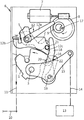
도 1의 기능적 위치에서 도 2로의 이행 동안 설명된 닫힘 과정은 중단될 수 있다. 예를 들어, 손, 손가락 또는 코트 등이 천천히 닫혀지는 차량 도어와 차체 사이에 걸리는 경우에 이 닫힘 과정 중단이 필요하다. 전형적으로, 이는 비상 중단으로 불린다. 이 비상 중단을 세부적으로 실행하기 위하여, 개방 구동부(7 내지 11)는 닫힘 폴(16)이 꺼내지는 것을 보장한다. 이는 닫힘 구동부(13, 14)로부터 닫힘 이송 레버(15), 닫힘 폴(16) 그리고 로터리 래치(1)까지의 기계적 연결이 개방 구동부(7 내지 11)의 도움으로 중단된다는 것을 의미한다. The closing process described during the transition to FIG. 2 in the functional position of FIG. 1 can be interrupted. For example, if a hand, finger or coat is caught between the vehicle door and the vehicle body which is slowly closed, this closing process is needed to stop. Typically, this is called an emergency stop. In order to carry out this emergency interruption in detail, the
이 목적을 위하여, 개방 이송 레버(12)는 위에서 언급된 작동 요소(21)를 포함한다. 작동 요소(21)는 -설명한 바와 같은- 개방 기능 동안 폴(2)이 록킹 메커니즘(1, 2)의 로터리 래치(1)로부터 들어 올려지는 것을 보장한다. 덧붙여, 작동 요소(21)는 또한 이하에서 상세하게 설명된 바와 같이 닫힘 기능을 중단하도록 설계되어 있다. 본 실시예에서 도시된 바와 같이, 작동 요소(21)는 실제로 닫힘 폴(16)과 직접적으로 상호 작용하거나 상류 이젝터 레버(18)를 통하여 닫힘 폴(16)과 상호 작용하여 닫힘 기능을 중단시킨다. For this purpose, the
작동 요소(21)는 개방 이송 레버(12)와 비교하여 수직적으로 연장된 작동 저널로서 설계된다. 닫힘 기능을 중단시키기 위하여, 이송 레버(12)의 작동 아암(12c) 상에 배치된 작동 저널(21)은 이젝터 레버(18)에 작용하며, 따라서 닫힘 폴(16)은 로터리 래치(1)와의 맞물림으로부터 제거된다. 동시에, 작동 저널(21)은 폴(2)이 로터리 래치(1)로부터 들어 올려지는 것을 보장한다. 이 과정을 시작하기 위하여, 도시되지 않지만 레버가 차실 내에 제공될 수 있으며, 이 레버는 기계적인 개방 구동부(10, 11)로서 작용하고 결합 요소(11)를 통하여 개방 이송 레버(12)와 맞물린다. 대안적으로, 개방 이송 레버(12) 또한 전기적 개방 구동부(7 내지 9)의 도움으로 작동할 수 있다. The
시스템은 다음과 같이 기능을 수행한다. 록킹 메커니즘(1, 2)이 당겨져 닫혀지자 마자, 닫힘 이송 레버(15)는 닫힘 폴(16)이 이 과정을 뒤따르는 것을 보장한다. 실제로 닫힘 이송 레버(15), 이 레버 상에 장착된 닫힘 폴(16) 그리고 닫힘 폴(16)이 저널(20)에 접촉함에 따라 회전하는 로터리 래치(1) 모두는 시계 방향으로 선회한다. 이는 또한 이젝터 레버(18)를 위하여 적용된다. 이 과정이 도 1에 도시되어 있다. The system performs the following functions. As soon as the locking
닫힘 과정을 중단시키기 위하여, 도 3에 도시된 바와 같이, 개방 이송 레버(12) 전부는 그 축(5)을 중심으로 하는 반시계 방향으로의 선회 운동을 수행할 수 있다. 이는 전기 모터(7)에 의하여 작동하는 캠(9)의 도움으로 이루어지며 또한 기계적인 개방 구동부(10, 11)가 결합 요소(11)를 통하여 개방 이송 레버(12)의 연결 아암(12b)에 작용한다는 사실에 의하여 이루어진다. 어떠한 경우에, 기계적 및/또는 전기적 개방 구동부(7 내지 11)에 의한 닫힘 과정의 각각의 중단은 축(5)을 중심으로 하는 설명된 반시계 방향 선회 이동을 수행하는 개방 이송 레버(12)와 부합한다. In order to stop the closing process, as shown in FIG. 3, all of the open transfer levers 12 can carry out a counterclockwise rotational movement about their
그 결과, 작동 저널(21)은 이젝터 레버(18)에 작용하며, 이젝터 레버는 닫힘 폴(16)과 공유된 축(19)을 중심으로 시계 방향으로 선회한다. 이 과정 동안에, 이젝터 레버(18)는 닫힘 폴(16) 상의 저널(22)에 작용하여 닫힘 폴(16)은 전체적으로 로터리 래치(1) 상의 저널(20)로부터 전체적으로 들어 올려진다. 로터리 래치(1)는 해제된다 (축(3)을 중심으로 하는 로터리 래치(1)의 관련된 반시계 방향의 이동을 나타내는 도 3에 나타난 화살표 참조). 본 발명에 따르면, 스프링 력의 결과로서 작용하는 경우 전체 닫힘 과정 동안에 이젝터 레버는 작동 저널(21)에 부딪힌다. As a result, the
설명된 과정 동안에, 작동 저널(21)은 로터리 래치(1)에 부딪히는 또는 로터리 래치(1)에 맞물리는 폴(2)이 로터리 래치(1)로부터 들어 올려지는 것을 보장한다. 이 목적을 위하여, 작동 저널(21)의 종단은 폴(2)에 작용하여 폴(2)이 축(5)을 중심으로 반시계 방향으로 선회하는 것을 보장한다. 그 결과, 폴(2)은 로터리 래치(1)로부터 들어 올려진다. During the process described, the working
실제적으로 동시에 일어나는 설명된 양 과정은 축(3)을 중심으로 반시계 반향으로 선회함에 의하여 스프링 력에 의해 로터리 래치(1)가 개방되게 한다. 그 결과, 이전에 포획된 록킹 볼트(4)는 해제된다. 분명하게 도시되지 않았지만, 동일한 과정이 록킹 볼트(4)에 기계적으로 연결된 차량 도어에 적용된다. Both described processes that occur at the same time in real time cause the rotary latch 1 to be opened by spring force by turning counterclockwise about the
이는 기계적 및/또는 전기적 개방 구동부(7 내지 11)의 도움으로의 닫힘의 중단이 또한 폴(2)이 로터리 래치(1)로부터 들어 올려지는 것을 야기한다는 것을 의미한다. 그 결과, 로터리 래치(1)는 충돌없이 그리고 스프링 력의 도움으로 상향 선회할 수 있어 록킹 볼트(4)를 해제한다. 이는 개방 구동부(7 내지 11)의 도움으로 직접적이고 그리고 신뢰성 있는 닫힘 기능의 비상 중단을 발생시킨다. This means that the interruption of the closure with the aid of the mechanical and / or electrically
Claims (15)
Applications Claiming Priority (3)
| Application Number | Priority Date | Filing Date | Title |
|---|---|---|---|
| DE102011012656.2 | 2011-02-28 | ||
| DE201110012656 DE102011012656A1 (en) | 2011-02-28 | 2011-02-28 | Motor vehicle door lock |
| PCT/DE2012/000195 WO2012116686A2 (en) | 2011-02-28 | 2012-02-24 | Motor vehicle door lock |
Publications (1)
| Publication Number | Publication Date |
|---|---|
| KR20140010072A true KR20140010072A (en) | 2014-01-23 |
Family
ID=46017733
Family Applications (1)
| Application Number | Title | Priority Date | Filing Date |
|---|---|---|---|
| KR20137024207A KR20140010072A (en) | 2011-02-28 | 2012-02-24 | Motor vehicle door lock |
Country Status (8)
| Country | Link |
|---|---|
| US (1) | US9810004B2 (en) |
| EP (1) | EP2681388B1 (en) |
| JP (1) | JP6051433B2 (en) |
| KR (1) | KR20140010072A (en) |
| CN (1) | CN103502550B (en) |
| CA (1) | CA2827996A1 (en) |
| DE (1) | DE102011012656A1 (en) |
| WO (1) | WO2012116686A2 (en) |
Families Citing this family (38)
| Publication number | Priority date | Publication date | Assignee | Title |
|---|---|---|---|---|
| EP3567196A1 (en) * | 2010-02-05 | 2019-11-13 | Magna Closures SpA | Vehicular latch with double pawl arrangement |
| DE202012003171U1 (en) * | 2012-03-28 | 2013-07-01 | Kiekert Aktiengesellschaft | Motor vehicle door lock |
| DE102012207443A1 (en) * | 2012-05-04 | 2013-11-07 | Kiekert Ag | Lock for a flap or door |
| DE102012216976B4 (en) | 2012-09-21 | 2023-11-09 | Kiekert Aktiengesellschaft | Lock for a flap or door |
| DE202012010338U1 (en) * | 2012-10-30 | 2014-02-03 | Kiekert Aktiengesellschaft | Motor vehicle door lock |
| DE102012023236A1 (en) * | 2012-11-28 | 2014-05-28 | Kiekert Aktiengesellschaft | Motor vehicle door lock |
| US9920555B2 (en) * | 2013-01-18 | 2018-03-20 | Kiekert Ag | Lock for a motor vehicle |
| US9593511B2 (en) | 2013-03-27 | 2017-03-14 | Kiekert Ag | Lock for a motor vehicle |
| DE102013103245A1 (en) * | 2013-03-28 | 2014-10-02 | Kiekert Aktiengesellschaft | Motor vehicle door lock |
| JP5972919B2 (en) * | 2014-02-04 | 2016-08-17 | 本田技研工業株式会社 | Vehicle door device |
| US20150250312A1 (en) * | 2014-03-05 | 2015-09-10 | Advantage Pharmacy Services Llc | Pivotable Spring-Loadable Product |
| DE102014003737A1 (en) * | 2014-03-18 | 2015-09-24 | Kiekert Aktiengesellschaft | Closing device for a motor vehicle hood |
| KR101560979B1 (en) * | 2014-05-30 | 2015-10-15 | 평화정공 주식회사 | Hood latch having dual unlocking function |
| DE102014107771A1 (en) * | 2014-06-03 | 2015-12-03 | Wietmarscher Ambulanz- Und Sonderfahrzeug Gmbh | locking mechanism |
| DE202014103819U1 (en) * | 2014-08-18 | 2015-11-19 | BROSE SCHLIEßSYSTEME GMBH & CO. KG | Motor vehicle lock |
| FR3027045A1 (en) * | 2014-10-08 | 2016-04-15 | Inteva Products Llc | |
| US20160168883A1 (en) * | 2014-12-15 | 2016-06-16 | GM Global Technology Operations LLC | Double pull action vehicle hood latch |
| CN107407110B (en) * | 2015-02-17 | 2019-07-26 | Gecom公司 | Automobile-use door latch apparatus |
| KR101836620B1 (en) * | 2016-04-21 | 2018-03-08 | 현대자동차주식회사 | Cinching latch assembly for vehicle |
| DE102016107507A1 (en) * | 2016-04-22 | 2017-10-26 | Kiekert Ag | Curing aid for motor vehicles |
| DE102017209376A1 (en) * | 2016-06-07 | 2017-12-07 | Magna Closures Inc. | Vehicle lock latch assembly with double pawl latch mechanism |
| US20180058112A1 (en) * | 2016-09-01 | 2018-03-01 | AISIN Technical Center of America, Inc. | Vehicle door closing and releasing apparatus |
| DE102016011162A1 (en) * | 2016-09-16 | 2018-03-22 | Magna BÖCO GmbH | Locking device for a vehicle door and method |
| JP6609826B2 (en) * | 2016-09-30 | 2019-11-27 | 三井金属アクト株式会社 | Vehicle door latch device |
| DE102016121083A1 (en) | 2016-11-04 | 2018-05-09 | Kiekert Ag | MOTOR VEHICLE DOOR |
| KR20180071434A (en) * | 2016-12-19 | 2018-06-28 | 현대자동차주식회사 | Switchger of tailgate for vehicle |
| KR20180071435A (en) * | 2016-12-19 | 2018-06-28 | 현대자동차주식회사 | Switchger of tailgate for vehicle |
| CN107060533A (en) * | 2017-03-29 | 2017-08-18 | 绍兴市上虞永生汽车部件有限公司 | The device of emergency release is realized using the rotation shift fork associated with external-open mechanism action |
| US11377880B2 (en) * | 2017-05-25 | 2022-07-05 | Magna Closures Inc. | Vehicular latch assembly with latch mechanism having self-locking ratchet |
| DE102017009902A1 (en) | 2017-10-24 | 2019-04-25 | Daimler Ag | Lock actuator with emergency opening function |
| CN107654133A (en) * | 2017-10-31 | 2018-02-02 | 无锡瑞林控制软件有限公司 | Self-priming side door lock transmission mechanism |
| US20190301212A1 (en) * | 2018-03-27 | 2019-10-03 | Magna BOCO GmbH | Closure latch assembly with latch mechanism having a dual-pawl configuration |
| JP7052173B2 (en) * | 2018-10-01 | 2022-04-12 | 三井金属アクト株式会社 | Vehicle door latch device |
| WO2021143980A1 (en) | 2020-01-14 | 2021-07-22 | Kiekert Ag | Motor vehicle lock |
| DE102020102336A1 (en) * | 2020-01-30 | 2021-08-05 | Brose Schließsysteme GmbH & Co. Kommanditgesellschaft | Front hood lock for a motor vehicle |
| FR3111371B1 (en) * | 2020-06-11 | 2022-10-07 | Minebea Mitsumi Inc | Electric locking mechanism for a sash including a mechanical emergency function |
| DE102020118721A1 (en) * | 2020-07-15 | 2022-01-20 | Kiekert Aktiengesellschaft | motor vehicle lock |
| US11680435B2 (en) * | 2020-11-17 | 2023-06-20 | Brose Fahrzeugteile Gmbh & Co. Kommanditgesellschaft, Bamberg | Single drive system for driving multiple driven assemblies |
Family Cites Families (43)
| Publication number | Priority date | Publication date | Assignee | Title |
|---|---|---|---|---|
| IT1196889B (en) * | 1986-12-30 | 1988-11-25 | Gilardini Spa | ELECTRICALLY OPERABLE LOCK FOR APPLICATION ON MOTOR VEHICLES |
| DE3836771A1 (en) * | 1988-07-16 | 1990-01-18 | Daimler Benz Ag | Motor-vehicle door lock, bonnet lock or the like with a motive locking aid |
| JP2658272B2 (en) * | 1988-09-30 | 1997-09-30 | アイシン精機株式会社 | Door closing device |
| US5411302A (en) * | 1992-06-29 | 1995-05-02 | Ohi Seisakusho Co., Ltd. | Powered closing device |
| JP2847459B2 (en) * | 1993-04-07 | 1999-01-20 | 三井金属鉱業株式会社 | Automatic door lock device for sliding doors |
| DE4319122C1 (en) * | 1993-06-09 | 1994-10-20 | Daimler Benz Ag | Power-assisted rotary-latch closure for vehicles |
| JP2855557B2 (en) * | 1993-07-30 | 1999-02-10 | 株式会社大井製作所 | Door lock device for automobile |
| US5639130A (en) * | 1995-05-31 | 1997-06-17 | General Motors Corporation | Rotary door cinching mechanism with manual override |
| DE29612524U1 (en) * | 1996-07-19 | 1996-10-02 | Kiekert Ag | Device for closing and closing as well as opening the tailgate of a motor vehicle |
| DE19828040B4 (en) * | 1998-06-24 | 2005-05-19 | Siemens Ag | Power assisted closing device |
| JP4227684B2 (en) * | 1998-07-08 | 2009-02-18 | 株式会社城南製作所 | Door lock device |
| US6422615B1 (en) * | 1998-07-20 | 2002-07-23 | Mannesmann Vdo Ag | Closure device with shutting aid |
| DE19933371A1 (en) * | 1998-08-11 | 2000-02-17 | Mannesmann Vdo Ag | Locking device with closing aid |
| DE19919765A1 (en) * | 1999-04-29 | 2000-11-09 | Bosch Gmbh Robert | Motor vehicle door lock or the like. with electrical opening aid and closing aid |
| US6550825B2 (en) * | 2000-06-06 | 2003-04-22 | Delphi Technologies, Inc. | Cinching door latch with planetary release mechanism |
| JP4474811B2 (en) * | 2000-11-27 | 2010-06-09 | 株式会社デンソー | Door lock drive device |
| DE10114438A1 (en) * | 2001-03-23 | 2002-10-02 | Siemens Ag | Locking device with closing aid |
| DE10155307A1 (en) * | 2001-11-10 | 2003-05-22 | Bayerische Motoren Werke Ag | Lock with motorised pull-to device has coupling nose of lever only engaging with force in coupling ratchet of rotary catch when there is no resistance through jammed body part etc |
| DE10157597B4 (en) * | 2001-11-23 | 2013-07-18 | Witte-Strattec Llc | Motor vehicle door lock |
| DE10164438A1 (en) | 2001-12-29 | 2003-07-10 | Witte Velbert Gmbh & Co Kg | Rotating locking mechanism for motor vehicle doors has a retracting element to ensure the door sealing is established |
| DE10216845B4 (en) * | 2002-04-16 | 2005-06-30 | Atoma International Corp. Germany | Lock, in particular motor vehicle rear lock |
| DE10251382A1 (en) * | 2002-11-01 | 2004-05-13 | Siemens Ag | Method for actuating a pawl in a lock with a rotary latch for a motor vehicle |
| FR2850698A1 (en) * | 2003-01-30 | 2004-08-06 | Valeo Securite Habitacle | Hatch lock for automobile vehicle, has opening assistance unit for discharging blocking unit that blocks latch in closing position and for activating disengaging unit to disengage closing assistance unit |
| JP4136903B2 (en) * | 2003-11-12 | 2008-08-20 | 三井金属鉱業株式会社 | Latch device |
| DE102004052599A1 (en) | 2004-10-29 | 2006-05-04 | Bayerische Motoren Werke Ag | Lock for motor vehicle door, has opening aid to produce torsional moment in closing direction of latch and activated by opening signal or movement of hand, handgrips or switches until pin is adjusted from opening adjustable range of latch |
| JP4502824B2 (en) * | 2005-01-11 | 2010-07-14 | 三井金属鉱業株式会社 | Vehicle door closer device |
| JP4444157B2 (en) * | 2005-05-10 | 2010-03-31 | 三井金属鉱業株式会社 | Door opener |
| DE102006024203B4 (en) * | 2005-05-24 | 2013-08-29 | Mitsui Kinzoku Act Corp. | Locking device and device for controlling a door opening / closing |
| DE102005048564A1 (en) * | 2005-10-11 | 2007-04-12 | Huf Hülsbeck & Fürst Gmbh & Co. Kg | Closing device in vehicles has latch and locking pawl with emergency actuator acting on bend area of elbow joint pairs to release rigid joint and pawl from latch if motor fails |
| JP4695549B2 (en) * | 2006-06-07 | 2011-06-08 | 三井金属アクト株式会社 | Door opener |
| JP4851869B2 (en) * | 2006-07-03 | 2012-01-11 | 三井金属アクト株式会社 | Vehicle door latch device |
| DE102007003948A1 (en) * | 2006-11-22 | 2008-05-29 | Kiekert Ag | Locking unit with multipart pawl |
| US20080224482A1 (en) * | 2007-02-15 | 2008-09-18 | Cumbo Francesco | Electrical Door Latch |
| DE102007052890A1 (en) * | 2007-11-02 | 2009-05-07 | Kiekert Ag | Motor vehicle door lock |
| JP4962283B2 (en) * | 2007-11-22 | 2012-06-27 | アイシン精機株式会社 | Vehicle door opening and closing device |
| DE102008009506A1 (en) | 2008-02-15 | 2009-08-20 | Kiekert Ag | Motor vehicle door lock |
| DE102008048772A1 (en) * | 2008-09-24 | 2010-03-25 | Kiekert Ag | Motor vehicle door lock |
| DE102008048773A1 (en) * | 2008-09-24 | 2010-03-25 | Kiekert Ag | Motor vehicle door lock |
| DE202008015789U1 (en) | 2008-11-28 | 2010-04-22 | Kiekert Ag | Motor vehicle door lock |
| CN201531171U (en) * | 2009-10-16 | 2010-07-21 | 镇江美驰轻型车系统(第二)有限公司 | Emergency locking device for a door lock in automobile collision |
| DE102012003743A1 (en) * | 2012-02-28 | 2013-08-29 | Kiekert Aktiengesellschaft | Motor vehicle door lock |
| DE202013102505U1 (en) * | 2012-09-07 | 2013-06-17 | Kiekert Aktiengesellschaft | Zuzieheinrichtung for a motor vehicle lock |
| DE202012010338U1 (en) * | 2012-10-30 | 2014-02-03 | Kiekert Aktiengesellschaft | Motor vehicle door lock |
-
2011
- 2011-02-28 DE DE201110012656 patent/DE102011012656A1/en not_active Withdrawn
-
2012
- 2012-02-24 JP JP2013555750A patent/JP6051433B2/en active Active
- 2012-02-24 US US14/001,923 patent/US9810004B2/en active Active
- 2012-02-24 KR KR20137024207A patent/KR20140010072A/en not_active Application Discontinuation
- 2012-02-24 WO PCT/DE2012/000195 patent/WO2012116686A2/en active Application Filing
- 2012-02-24 EP EP12717152.8A patent/EP2681388B1/en active Active
- 2012-02-24 CA CA 2827996 patent/CA2827996A1/en not_active Abandoned
- 2012-02-24 CN CN201280020333.XA patent/CN103502550B/en active Active
Also Published As
| Publication number | Publication date |
|---|---|
| DE102011012656A1 (en) | 2012-08-30 |
| US20140049056A1 (en) | 2014-02-20 |
| US9810004B2 (en) | 2017-11-07 |
| EP2681388B1 (en) | 2018-04-04 |
| CN103502550B (en) | 2015-10-07 |
| CN103502550A (en) | 2014-01-08 |
| CA2827996A1 (en) | 2012-09-07 |
| EP2681388A2 (en) | 2014-01-08 |
| JP2014511446A (en) | 2014-05-15 |
| JP6051433B2 (en) | 2016-12-27 |
| WO2012116686A2 (en) | 2012-09-07 |
| WO2012116686A3 (en) | 2012-11-01 |
Similar Documents
| Publication | Publication Date | Title |
|---|---|---|
| KR20140010072A (en) | Motor vehicle door lock | |
| US8757682B2 (en) | Motor vehicle door lock | |
| US8757681B2 (en) | Motor vehicle door lock | |
| JP6255631B2 (en) | Automotive door closing device | |
| US9574379B2 (en) | Motor vehicle door lock | |
| US10508476B2 (en) | Electric vehicle door lock with increased operating reliability | |
| EP3140479B1 (en) | Closure and latching mechanisms | |
| US11933091B2 (en) | Motor-vehicle door lock | |
| KR102005604B1 (en) | Lock for a flap or door | |
| CN103670065B (en) | Vehicle door latch system | |
| KR20100123658A (en) | Vehicle lock | |
| US20140203570A1 (en) | Actuating device | |
| GB2458567A (en) | Door latch in a motor vehicle | |
| US20150308156A1 (en) | Closing mechanism for a motor vehicle comprising a closing aid | |
| KR20220005078A (en) | car door lock | |
| CN113710863B (en) | Door lock, in particular motor vehicle door lock | |
| CN110857606B (en) | Lock for a hood of a vehicle | |
| WO2013139109A1 (en) | Electric locking-type outward swinging door | |
| CN114080484A (en) | Motor vehicle door lock | |
| EP2112306B1 (en) | Vehicle door latch apparatus | |
| EP3029230B1 (en) | Relay mechanism of vehicle sliding door | |
| CN215485361U (en) | Automobile side door lock with self-suction function | |
| TWI509142B (en) | Vehicle door lock device | |
| KR20240042068A (en) | Closure device for car locks | |
| CN113389446A (en) | Door lock, in particular motor vehicle door lock |
Legal Events
| Date | Code | Title | Description |
|---|---|---|---|
| WITN | Application deemed withdrawn, e.g. because no request for examination was filed or no examination fee was paid |