EP3029230B1 - Relay mechanism of vehicle sliding door - Google Patents
Relay mechanism of vehicle sliding door Download PDFInfo
- Publication number
- EP3029230B1 EP3029230B1 EP15196970.6A EP15196970A EP3029230B1 EP 3029230 B1 EP3029230 B1 EP 3029230B1 EP 15196970 A EP15196970 A EP 15196970A EP 3029230 B1 EP3029230 B1 EP 3029230B1
- Authority
- EP
- European Patent Office
- Prior art keywords
- lever
- open
- sliding door
- child
- lock
- Prior art date
- Legal status (The legal status is an assumption and is not a legal conclusion. Google has not performed a legal analysis and makes no representation as to the accuracy of the status listed.)
- Active
Links
- 230000007246 mechanism Effects 0.000 title claims description 60
- 238000010586 diagram Methods 0.000 description 6
- 230000008878 coupling Effects 0.000 description 4
- 238000010168 coupling process Methods 0.000 description 4
- 238000005859 coupling reaction Methods 0.000 description 4
- 230000002265 prevention Effects 0.000 description 3
- 230000009471 action Effects 0.000 description 2
- 238000010276 construction Methods 0.000 description 1
- 238000005516 engineering process Methods 0.000 description 1
- 230000002452 interceptive effect Effects 0.000 description 1
- 238000000034 method Methods 0.000 description 1
- 238000012986 modification Methods 0.000 description 1
- 230000004048 modification Effects 0.000 description 1
- 239000002699 waste material Substances 0.000 description 1
Images


Classifications
-
- E—FIXED CONSTRUCTIONS
- E05—LOCKS; KEYS; WINDOW OR DOOR FITTINGS; SAFES
- E05B—LOCKS; ACCESSORIES THEREFOR; HANDCUFFS
- E05B77/00—Vehicle locks characterised by special functions or purposes
- E05B77/22—Functions related to actuation of locks from the passenger compartment of the vehicle
- E05B77/24—Functions related to actuation of locks from the passenger compartment of the vehicle preventing use of an inner door handle, sill button, lock knob or the like
- E05B77/28—Functions related to actuation of locks from the passenger compartment of the vehicle preventing use of an inner door handle, sill button, lock knob or the like for anti-theft purposes, e.g. double-locking or super-locking
-
- E—FIXED CONSTRUCTIONS
- E05—LOCKS; KEYS; WINDOW OR DOOR FITTINGS; SAFES
- E05B—LOCKS; ACCESSORIES THEREFOR; HANDCUFFS
- E05B77/00—Vehicle locks characterised by special functions or purposes
- E05B77/22—Functions related to actuation of locks from the passenger compartment of the vehicle
- E05B77/24—Functions related to actuation of locks from the passenger compartment of the vehicle preventing use of an inner door handle, sill button, lock knob or the like
- E05B77/245—Functions related to actuation of locks from the passenger compartment of the vehicle preventing use of an inner door handle, sill button, lock knob or the like by blocking the movement of a movable element
-
- E—FIXED CONSTRUCTIONS
- E05—LOCKS; KEYS; WINDOW OR DOOR FITTINGS; SAFES
- E05B—LOCKS; ACCESSORIES THEREFOR; HANDCUFFS
- E05B77/00—Vehicle locks characterised by special functions or purposes
- E05B77/22—Functions related to actuation of locks from the passenger compartment of the vehicle
- E05B77/30—Functions related to actuation of locks from the passenger compartment of the vehicle allowing opening by means of an inner door handle, even if the door is locked
-
- E—FIXED CONSTRUCTIONS
- E05—LOCKS; KEYS; WINDOW OR DOOR FITTINGS; SAFES
- E05B—LOCKS; ACCESSORIES THEREFOR; HANDCUFFS
- E05B83/00—Vehicle locks specially adapted for particular types of wing or vehicle
- E05B83/36—Locks for passenger or like doors
- E05B83/40—Locks for passenger or like doors for sliding doors
Definitions
- a relay mechanism of a vehicle sliding door having the features according to claim 1.
- FIG. 1 A side surface of a vehicle body 11 having a sliding door 10 is illustrated in FIG. 1 .
- the sliding door 10 is opened and closed by sliding in the front-back direction along the side surface of the vehicle body 11.
- the sliding door 10 has an outer open handle 12 and an inner open handle 13.
- the sliding door 10 has a front-side latch unit 15, which engages with a front-side striker 14 fixed to the vehicle body 11, on a front end.
- the sliding door 10 has a rear-side latch unit 17, which engages with a rear-side striker 16 fixed to the vehicle body 11, on a rear end.
- the sliding door 10 is held in a door closed state by engaging the front-side latch unit 15 with the front-side striker 14 and engaging the rear-side latch unit 17 with the rear-side striker 16.
- a sill knob and a door key cylinder are not provided in the sliding door 10.
- a relay mechanism 18 is attached in the sliding door 10, and the open handles 12 and 13 are respectively coupled with the latch units 15 and 17 by the relay mechanism 18.
- the relay mechanism 18 has a base plate 19 fixed to a metallic inner plate of the sliding door 10.
- An outer open lever 21 ( FIG. 7 ) is rotatably attached to the base plate 19 with a central shaft 20.
- An arc-shaped hole 22 having the central shaft 20 as the center is provided in an arm unit extending upward of the outer open lever 21.
- An end portion of a coupling tool 23 ( FIG. 3 ) such as a rod which extends to the outer open handle 12 is engaged with the arc-shaped hole 22.
- an L-shaped hole 24 is formed in the arm unit extending to the right of the outer open lever 21.
- An outer lock pin 25 ( FIG. 3 ) is slidably engaged with the L-shaped hole 24.
- a ratchet lever 26 ( FIG. 8 ) is rotatably supported by the central shaft 20.
- the ratchet lever 26 is arranged to overlap with the outer open lever 21.
- An engagement window 27 which can be engaged with the outer lock pin 25 is provided in the ratchet lever 26.
- the engagement window 27 is overlapped with the L-shaped hole 24.
- the ratchet lever 26 is coupled with the front-side latch unit 15 and the rear-side latch unit 17 respectively with coupling tools 28 and 29 ( FIG. 8 ) such as a rod.
- An outer actuator 33 is fixed to the base plate 19.
- An output lever 34 of the outer actuator 33 is engaged with the outer lock lever 31.
- the inner open lever mechanism 35 is provided in the base plate 19 ( FIGS. 2 and 4 ).
- the inner open lever mechanism 35 includes a main inner open lever 37 ( FIG. 9 ) and a sub inner open lever 38 ( FIG. 10 ).
- the main inner open lever 37 and the sub inner open lever 38 are supported by the central shaft 20 and are integrally rotated by an elastic force of a pressed spring 36.
- the main inner open lever 37 is coupled with the inner open handle 13 via a coupling tool 39 such as a rod.
- a rotatable leg unit 40 of the sub inner open lever 38 is faced to an inner lock pin 42 which is slidably engaged with a horizontally long slot 41 of the ratchet lever 26.
- the rotatable leg unit 40 is engaged with the inner lock pin 42, and the ratchet lever 26 is rotated via the inner lock pin 42. Accordingly, the sliding door 10 is in a state where the door can be opened.
- a child-proof lever 48 ( FIG. 12 ) is supported by the lock shaft 44.
- the lock shaft 44 may be integrally formed with the child-proof lever 48.
- a vertically long slot 50 is provided in the child-proof lever 48, and the inner lock pin 42 is slidably engaged with the vertically long slot 50.
- the inner lock pin 42 moves in the horizontally long slot 41 of the ratchet lever 26 by the contact with the slot 50 and switched between a position which overlaps with a rotational locus of the rotatable leg unit 40 provided in the sub inner open lever 38 (non-child-proof position) and a position which separates from the rotational locus of the rotatable leg unit 40 (child-proof position).
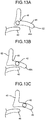
- FIG. 13B a state is illustrated where the inner lock lever 43 is lock-rotated (anti-theft rotation) from the state of FIG. 13A .
- the inner lock pin 42 is positioned in the block slot 45A, and the state is switched to the anti-theft state.
- the inner lock pin 42 cannot move upward as it has a contact with the block slot 45A, and the mechanism block is performed. Therefore, the state becomes excellent in crime prevention.
- the lock levers 31 and 43 are respectively provided in the outer open handle 12 and the inner open handle 13, and the respective levers can be individually switched. However, naturally, when the sliding door 10 is locked, it is desirable that both of the lock levers 31 and 43 be switched to the locked state (anti-theft state) by the actuators 33 and 46.
- the inner lock pin can be commonly used in the child-proof mechanism and the anti-theft mechanism, the design can be reasonable.
- the structure is more specific, and the design can be easily realized.
Description
- The present invention relates to a relay mechanism of a vehicle sliding door, and specifically, to a relay mechanism which transmits an operating force from an open handle of the door to a latch unit of the door while performing relay control to the operating force.
- An "anti-theft mechanism (double lock mechanism)" and a "child-proof mechanism" have been provided in a relay mechanism and a latch unit in the related art(see Japanese Patent Application Laid-open No.
2009-30362 2009-30363 8-74455 2000-345751 - An anti-theft mechanism, which has been proposed until now, has acted relative to a single lock lever of a locking/unlocking mechanism. That is, the lock lever functions relative to both the outer open handle and the inner open handle of the door. When the lock lever is in the unlocked state, the door can be opened by both the open handles. When the lock lever is in the locked state, the door cannot be opened by both the open handles.
- However, in recent years, a number of doors in which an inside lock operating unit (sill knob) is omitted has been employed. When the sill knob-less relay mechanism and the latch unit in which the sill knob is omitted are designed, there is a problem in that the conventional anti-theft mechanism for a common lock lever has less generality, and especially, waste is increased in a combination with the child-proof mechanism.
-
EP 1 030 013 A1 describes a relay mechanism for a vehicle door according to the preamble of claim 1. In -
WO 00/79079 A1 WO 98/33998 US 5,676,003 describes a central locking system for motor vehicles that has all of the opening and closing functions occurring in normal operation also in the event of failure of individual components. Finally,EP 1 059 407 A2 describes a vehicle door latch providing a power child security lock for a vehicle door. - It is an object of the present invention to at least partially solve the problems in the conventional technology.
- To solve the problem described above, a relay mechanism of a vehicle sliding door is provided having the features according to claim 1.
- The above and other objects, features, advantages and technical and industrial significance of this invention will be better understood by reading the following detailed description of presently preferred embodiments of the invention, when considered in connection with the accompanying drawings.
-
-
FIG. 1 is a side view of a relation between a sliding door and a vehicle body to which a relay mechanism has been applied; -
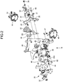
FIG. 2 is an exploded sectional view of the relay -
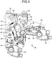
FIG. 3 is a rear view of the relay mechanism; -
FIG. 4 is a front view of the relay mechanism; -
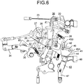
FIG. 5 is an enlarged rear view of a main part of the relay mechanism; -
FIG. 6 is an enlarged front view of the main part of the relay mechanism; -
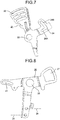
FIG. 7 is a rear view of an outer open lever which is applied to the relay mechanism; -
FIG. 8 is a rear view of a ratchet lever which is applied to the relay mechanism; -
FIG. 9 is a front view of a main inner open lever which is applied to the relay mechanism; -
FIG. 10 is a front view of a sub inner open lever which is applied to the relay mechanism; -
FIG. 11 is a front view of an inner lock lever which is applied to the relay mechanism; -
FIG. 12 is a front view of a child-proof lever which is applied to the relay mechanism; and -
FIGS. 13A to 13C are action brief explanatory diagrams of the relay mechanism.FIG. 13A is a diagram of a state where the inner lock lever is placed at an unlock position.FIG. 13B is a diagram of a state where the inner lock lever is placed at a lock position (anti-theft position).FIG. 13C is a diagram of a child-proof state. - One embodiment of the present invention will be described with reference to the drawings. A side surface of a
vehicle body 11 having a slidingdoor 10 is illustrated inFIG. 1 . The slidingdoor 10 is opened and closed by sliding in the front-back direction along the side surface of thevehicle body 11. As is well known, the slidingdoor 10 has an outeropen handle 12 and an inneropen handle 13. The slidingdoor 10 has a front-side latch unit 15, which engages with a front-side striker 14 fixed to thevehicle body 11, on a front end. The slidingdoor 10 has a rear-side latch unit 17, which engages with a rear-side striker 16 fixed to thevehicle body 11, on a rear end. The slidingdoor 10 is held in a door closed state by engaging the front-side latch unit 15 with the front-side striker 14 and engaging the rear-side latch unit 17 with the rear-side striker 16. In the present embodiment, a sill knob and a door key cylinder are not provided in the slidingdoor 10. - A
relay mechanism 18 is attached in the slidingdoor 10, and theopen handles latch units relay mechanism 18. - A detail on the
relay mechanism 18 will be illustrated afterFIG. 2 . Therelay mechanism 18 has abase plate 19 fixed to a metallic inner plate of the slidingdoor 10. An outer open lever 21 (FIG. 7 ) is rotatably attached to thebase plate 19 with acentral shaft 20. An arc-shaped hole 22 having thecentral shaft 20 as the center is provided in an arm unit extending upward of the outeropen lever 21. An end portion of a coupling tool 23 (FIG. 3 ) such as a rod which extends to the outeropen handle 12 is engaged with the arc-shaped hole 22. When the outeropen handle 12 is rotated to open the door, the outeropen lever 21 rotates clockwise inFIG. 3 . - As illustrated in
FIG. 7 , an L-shaped hole 24 is formed in the arm unit extending to the right of the outeropen lever 21. An outer lock pin 25 (FIG. 3 ) is slidably engaged with the L-shaped hole 24. - A ratchet lever 26 (
FIG. 8 ) is rotatably supported by thecentral shaft 20. Theratchet lever 26 is arranged to overlap with the outeropen lever 21. Anengagement window 27 which can be engaged with theouter lock pin 25 is provided in theratchet lever 26. Theengagement window 27 is overlapped with the L-shapedhole 24. Theratchet lever 26 is coupled with the front-side latch unit 15 and the rear-side latch unit 17 respectively withcoupling tools 28 and 29 (FIG. 8 ) such as a rod. When theratchet lever 26 rotates clockwise inFIG. 3 , thelatch units strikers - Two pieces of an
outer lock lever 31 is rotatably attached to thebase plate 19 with alock shaft 30, and the two pieces of theouter lock lever 31 are coupled with thelock shaft 30. Aslot 32 with which theouter lock pin 25 is slidably engaged is provided in theouter lock lever 31. When theouter lock lever 31 rotates, theouter lock pin 25 moves in an engageslot 24A of the L-shapedhole 24. - As illustrated in
FIG. 3 , when theouter lock pin 25 moves in the engageslot 24A and moves to a position close to thecentral shaft 20, a state of the door becomes an unlocked state. In the unlocked state, clockwise rotation of the outeropen lever 21 is transmitted to theratchet lever 26 via theouter lock pin 25, and the slidingdoor 10 can be opened. On the other hand, when theouter lock pin 25 is separated from thecentral shaft 20 and moves to a position to face to auselessly swinging slot 24B of the L-shapedhole 24, the state of the door becomes a locked state. In the locked state, even when the outeropen lever 21 rotates clockwise, theouter lock pin 25 relatively moves in theuselessly swinging slot 24B. Accordingly, theratchet lever 26 does not rotate, and an operation to open the door becomes invalid. - An
outer actuator 33 is fixed to thebase plate 19. Anoutput lever 34 of theouter actuator 33 is engaged with theouter lock lever 31. - An inner
open lever mechanism 35 is provided in the base plate 19 (FIGS. 2 and4 ). The inneropen lever mechanism 35 includes a main inner open lever 37 (FIG. 9 ) and a sub inner open lever 38 (FIG. 10 ). The main inneropen lever 37 and the sub inneropen lever 38 are supported by thecentral shaft 20 and are integrally rotated by an elastic force of a pressedspring 36. The main inneropen lever 37 is coupled with the inneropen handle 13 via acoupling tool 39 such as a rod. - A
rotatable leg unit 40 of the sub inneropen lever 38 is faced to aninner lock pin 42 which is slidably engaged with a horizontallylong slot 41 of theratchet lever 26. When the sub inneropen lever 38 rotates, therotatable leg unit 40 is engaged with theinner lock pin 42, and theratchet lever 26 is rotated via theinner lock pin 42. Accordingly, the slidingdoor 10 is in a state where the door can be opened. - An inner lock lever 43 (
FIG. 11 ) is provided on the side of the inneropen lever mechanism 35. Theinner lock lever 43 is attached to thebase plate 19 with alock shaft 44. An L-shapedhole 45 is provided in an upper portion of theinner lock lever 43, and theinner lock pin 42 is slidably engaged with the L-shapedhole 45. The L-shapedhole 45 includes ablock slot 45A having thelock shaft 44 as the center and afree slot 45B having thecentral shaft 20 as the center. When theinner lock lever 43 rotates, theinner lock pin 42 relatively moves in theblock slot 45A. Theinner lock lever 43 is coupled to anoutput lever 47 of aninner actuator 46. - When the
inner lock lever 43 is rotated counterclockwise from the state inFIG. 4 , theinner lock pin 42 relatively moves in theblock slot 45A. In this state, upward movement of theinner lock pin 42 is prevented by the engagement with theblock slot 45A, and the state becomes a mechanism block state. Therefore, when the sub inneropen lever 38 is rotated to open the door and therotatable leg unit 40 is engaged with theinner lock pin 42, theratchet lever 26 cannot be rotated. This state is to switch the state to the locked state by theinner lock lever 43, and also, this state is an anti-theft state where the rotation of theratchet lever 26 is prevented by the mechanism block state. - When the operation to open the door has been actually performed to the inner
open handle 13 in the anti-theft state, the main inneropen lever 37 is rotated via thecoupling tool 39, and the torque is transmitted to the sub inneropen lever 38 via the pressedspring 36. However, the sub inneropen lever 38 cannot rotate according to the mechanism block state made by theinner lock lever 43 and theinner lock pin 42, and the pressedspring 36 is elastically widened. Accordingly, an excessive operating force is not transmitted to the sub inneropen lever 38 and theinner lock pin 42, and damage of components is reduced. - A child-proof lever 48 (
FIG. 12 ) is supported by thelock shaft 44. Thelock shaft 44 may be integrally formed with the child-proof lever 48. When the slidingdoor 10 is in the door closed state, a switchingoperation knob 49 of the child-proof lever 48 is arranged at a position where the switchingoperation knob 49 cannot be operated as it is hidden from outside. - A vertically
long slot 50 is provided in the child-proof lever 48, and theinner lock pin 42 is slidably engaged with the verticallylong slot 50. When the child-proof lever 48 is switched, theinner lock pin 42 moves in the horizontallylong slot 41 of theratchet lever 26 by the contact with theslot 50 and switched between a position which overlaps with a rotational locus of therotatable leg unit 40 provided in the sub inner open lever 38 (non-child-proof position) and a position which separates from the rotational locus of the rotatable leg unit 40 (child-proof position). -
FIGS. 13A to 13C are action explanatory diagrams by using positions of theinner lock pin 42 and theinner lock lever 43. As illustrated inFIG. 13A , when theinner lock lever 43 is placed on the slightly right side relative to therotatable leg unit 40 and theinner lock pin 42 is placed on the left, theinner lock pin 42 is placed at a position facing to thefree slot 45B and overlapping with the rotational locus of therotatable leg unit 40. Therefore, the state becomes a normal unlocked state. That is, in this state, when therotatable leg unit 40 rotates, theinner lock pin 42 moves upward so that theratchet lever 26 is rotated. - Also, in
FIG. 13B , a state is illustrated where theinner lock lever 43 is lock-rotated (anti-theft rotation) from the state ofFIG. 13A . Theinner lock pin 42 is positioned in theblock slot 45A, and the state is switched to the anti-theft state. In this state, even when theinner lock pin 42 is made to move upward by rotating therotatable leg unit 40, theinner lock pin 42 cannot move upward as it has a contact with theblock slot 45A, and the mechanism block is performed. Therefore, the state becomes excellent in crime prevention. -
FIG. 13C is a diagram of a state where the child-proof lever 48 is switched from the state inFIG. 13A to the child-proof position. Although theinner lock pin 42 moves in theblock slot 45A, theinner lock lever 43 stays at the unlock position. This state is a normal child-proof state, and therotatable leg unit 40 uselessly swings without being engaged with theinner lock pin 42. - In the present invention, the lock levers 31 and 43 are respectively provided in the outer
open handle 12 and the inneropen handle 13, and the respective levers can be individually switched. However, naturally, when the slidingdoor 10 is locked, it is desirable that both of the lock levers 31 and 43 be switched to the locked state (anti-theft state) by theactuators - Also, as illustrated in
FIG. 13C , when a locking operation is performed in the child-proof state, theinner lock lever 43 rotates counterclockwise and is changed to a lock position (anti-theft position). At this time, since theblock slot 45A of theinner lock lever 43 has enough length, theblock slot 45A can move without interfering with theinner lock pin 42. Accordingly, when the child-proof state is continuously used, both or one of the lock levers 31 and 43 can be selectively switched by theactuators - In the embodiment of the present invention, since the lock lever is set relative to both the outer open handle and the inner open handle of the door, it is easy to design the anti-theft mechanism.
- In the embodiment of the present invention, since it is only necessary to set the child-proof mechanism relative to the inner lock lever for acting relative to the inner open handle, it is easy to design the anti-theft mechanism and the child-proof mechanism.
- In the embodiment of the present invention, since the inner lock pin can be commonly used in the child-proof mechanism and the anti-theft mechanism, the design can be reasonable.
- In the embodiment of the present invention, the structure is more specific, and the design can be easily realized.
- In the embodiment of the present invention, the crime prevention can be improved by using the anti-theft mechanism with a mechanism block, and a damage relative to a component caused by the unauthorized access can be reduced.
- Although the invention has been described with respect to specific embodiments for a complete and clear disclosure, the appended claims are not to be thus limited but are to be construed as embodying all modifications and alternative constructions that may occur to one skilled in the art that fairly fall within the basic teaching herein set forth.
Claims (4)
- A relay mechanism (18) of a vehicle sliding door (10), comprising:an outer open lever (21) configured to be coupled with an outer open handle (12) of a sliding door (10) and to release latch units (15, 17) to open the sliding door (10) when the outer open lever (21) is operated;an inner open lever mechanism (35) configured to be coupled with an inner open handle (13) of the sliding door (10) and to release the latch units (15, 17) to open the sliding door (10) when the inner open lever mechanism (35) is operated;an outer lock lever (31) configured to disable the release of the latch units (15, 17) by the operation of the outer open lever (21);an inner lock lever (43) configured to disable the release of the latch units (15, 17) by the operation of the inner open lever mechanism (35),the outer lock lever (31) and the inner lock lever (43) are individually switchable,a child-proof lever (48); andan inner lock pin (42) which is switched between a child-proof position and a non-child-proof position by the operation of the child-proof lever (48),characterized in that the inner lock lever (43) is configured to switch between an unlock position where the inner open lever mechanism (35) is operated and an anti-theft position where the inner open lever mechanism (35) is disabled to be operated.
- The relay mechanism (18) of the vehicle sliding door (10), according to claim 1, wherein
the inner lock lever (43) is configured to relatively move with respect to the inner lock pin 42 so as to be switched between the unlock position and the anti-theft position. - The relay mechanism (18) of the vehicle sliding door (10), according to any one of claims 1 to 2, wherein
when the inner lock lever (43) is placed at the anti-theft position, the inner lock lever (43) is configured to disable the operation of the inner open lever mechanism (35) by a mechanism block state. - The relay mechanism (18) of the vehicle sliding door (10), according to claim 3, wherein
the inner open lever mechanism (35) includes a main inner open lever (37) which is coupled with the inner open handle (13) without a play and a sub inner open lever (38) which is connected so as to rotate integrally with respect to the main inner open lever (37) by an elastic force of a pressed spring (36).
Applications Claiming Priority (1)
| Application Number | Priority Date | Filing Date | Title |
|---|---|---|---|
| JP2014245405A JP6450992B2 (en) | 2014-12-03 | 2014-12-03 | Vehicle sliding door relay mechanism |
Publications (2)
| Publication Number | Publication Date |
|---|---|
| EP3029230A1 EP3029230A1 (en) | 2016-06-08 |
| EP3029230B1 true EP3029230B1 (en) | 2019-10-23 |
Family
ID=54707693
Family Applications (1)
| Application Number | Title | Priority Date | Filing Date |
|---|---|---|---|
| EP15196970.6A Active EP3029230B1 (en) | 2014-12-03 | 2015-11-30 | Relay mechanism of vehicle sliding door |
Country Status (2)
| Country | Link |
|---|---|
| EP (1) | EP3029230B1 (en) |
| JP (1) | JP6450992B2 (en) |
Families Citing this family (1)
| Publication number | Priority date | Publication date | Assignee | Title |
|---|---|---|---|---|
| DE102015116283A1 (en) * | 2015-09-25 | 2017-03-30 | Kiekert Ag | Actuation device for a motor vehicle lock |
Citations (1)
| Publication number | Priority date | Publication date | Assignee | Title |
|---|---|---|---|---|
| EP1030013A1 (en) * | 1999-02-16 | 2000-08-23 | Valeo Securite Habitacle | Lock with a child safety function for a motor vehicle wing |
Family Cites Families (10)
| Publication number | Priority date | Publication date | Assignee | Title |
|---|---|---|---|---|
| DE4222868A1 (en) * | 1992-07-11 | 1994-01-13 | Bosch Gmbh Robert | Locking device for doors of a motor vehicle |
| JP2952161B2 (en) | 1994-08-31 | 1999-09-20 | 三井金属鉱業株式会社 | Anti-theft mechanism in door lock device |
| BR9807162A (en) * | 1997-02-04 | 2000-03-14 | Atoma Int Corp | Mechanically operated vehicle door locking device and system |
| JP3400747B2 (en) | 1999-06-03 | 2003-04-28 | 三井金属鉱業株式会社 | Vehicle door latch device with block type anti-theft mechanism |
| US6199923B1 (en) * | 1999-06-10 | 2001-03-13 | Delphi Technologies, Inc. | Vehicle door latch |
| US6328353B1 (en) * | 1999-06-16 | 2001-12-11 | Atoma International | Vehicle door latch assembly |
| JP4448870B2 (en) | 2007-07-27 | 2010-04-14 | 三井金属鉱業株式会社 | Relay operation device for vehicle door latch |
| JP4444315B2 (en) | 2007-07-27 | 2010-03-31 | 三井金属鉱業株式会社 | Relay operation device for vehicle door latch |
| JP4910218B2 (en) * | 2009-11-05 | 2012-04-04 | 三井金属アクト株式会社 | Door latch device for automobile |
| JP6131449B2 (en) * | 2013-02-07 | 2017-05-24 | 三井金属アクト株式会社 | Vehicle door opening and closing device |
-
2014
- 2014-12-03 JP JP2014245405A patent/JP6450992B2/en active Active
-
2015
- 2015-11-30 EP EP15196970.6A patent/EP3029230B1/en active Active
Patent Citations (1)
| Publication number | Priority date | Publication date | Assignee | Title |
|---|---|---|---|---|
| EP1030013A1 (en) * | 1999-02-16 | 2000-08-23 | Valeo Securite Habitacle | Lock with a child safety function for a motor vehicle wing |
Also Published As
| Publication number | Publication date |
|---|---|
| EP3029230A1 (en) | 2016-06-08 |
| JP2016108777A (en) | 2016-06-20 |
| JP6450992B2 (en) | 2019-01-16 |
Similar Documents
| Publication | Publication Date | Title |
|---|---|---|
| JP6236678B2 (en) | Car door lock | |
| RU2413825C2 (en) | Vehicle and door lock for vehicle door | |
| JP6051433B2 (en) | Automotive door lock | |
| EP1473428B1 (en) | A lock mechanism | |
| US6371538B1 (en) | Vehicle door latch device with block type anti-theft mechanism | |
| CN108603386B (en) | Door latch device for motor vehicle | |
| EP2460960B1 (en) | Door lock device for vehicle | |
| CN108138522B (en) | Actuating device for a motor vehicle lock | |
| JP2003090158A (en) | Gate lock device for vehicle | |
| JP6777678B2 (en) | Vehicle door latch device | |
| GB2477612A (en) | Vehicle latch with double locking | |
| US20180094460A1 (en) | Vehicular door latch device | |
| GB2458567A (en) | Door latch in a motor vehicle | |
| JP4555871B2 (en) | Door lock device | |
| CA2872071A1 (en) | Lock for a flap or door | |
| US6082158A (en) | Closing device | |
| KR101806612B1 (en) | vehicle door latch for preventing locking | |
| EP3029230B1 (en) | Relay mechanism of vehicle sliding door | |
| EP3081730B1 (en) | Vehicle door system comprising door latch device | |
| US10472868B2 (en) | Vehicle door latch device | |
| WO2020179098A1 (en) | Door latch device for automobile | |
| WO2011026014A2 (en) | Vehicle latch and method of operating | |
| JP4802341B2 (en) | Door lock device | |
| JP4967172B2 (en) | Door lock device | |
| GB2415740A (en) | Vehicle door lock apparatus |
Legal Events
| Date | Code | Title | Description |
|---|---|---|---|
| PUAI | Public reference made under article 153(3) epc to a published international application that has entered the european phase |
Free format text: ORIGINAL CODE: 0009012 |
|
| 17P | Request for examination filed |
Effective date: 20151130 |
|
| AK | Designated contracting states |
Kind code of ref document: A1 Designated state(s): AL AT BE BG CH CY CZ DE DK EE ES FI FR GB GR HR HU IE IS IT LI LT LU LV MC MK MT NL NO PL PT RO RS SE SI SK SM TR |
|
| AX | Request for extension of the european patent |
Extension state: BA ME |
|
| GRAP | Despatch of communication of intention to grant a patent |
Free format text: ORIGINAL CODE: EPIDOSNIGR1 |
|
| STAA | Information on the status of an ep patent application or granted ep patent |
Free format text: STATUS: GRANT OF PATENT IS INTENDED |
|
| INTG | Intention to grant announced |
Effective date: 20190628 |
|
| GRAS | Grant fee paid |
Free format text: ORIGINAL CODE: EPIDOSNIGR3 |
|
| GRAA | (expected) grant |
Free format text: ORIGINAL CODE: 0009210 |
|
| STAA | Information on the status of an ep patent application or granted ep patent |
Free format text: STATUS: THE PATENT HAS BEEN GRANTED |
|
| AK | Designated contracting states |
Kind code of ref document: B1 Designated state(s): AL AT BE BG CH CY CZ DE DK EE ES FI FR GB GR HR HU IE IS IT LI LT LU LV MC MK MT NL NO PL PT RO RS SE SI SK SM TR |
|
| REG | Reference to a national code |
Ref country code: GB Ref legal event code: FG4D |
|
| REG | Reference to a national code |
Ref country code: CH Ref legal event code: EP |
|
| REG | Reference to a national code |
Ref country code: IE Ref legal event code: FG4D |
|
| REG | Reference to a national code |
Ref country code: DE Ref legal event code: R096 Ref document number: 602015040192 Country of ref document: DE |
|
| REG | Reference to a national code |
Ref country code: AT Ref legal event code: REF Ref document number: 1193801 Country of ref document: AT Kind code of ref document: T Effective date: 20191115 |
|
| REG | Reference to a national code |
Ref country code: NL Ref legal event code: MP Effective date: 20191023 |
|
| REG | Reference to a national code |
Ref country code: LT Ref legal event code: MG4D |
|
| PG25 | Lapsed in a contracting state [announced via postgrant information from national office to epo] |
Ref country code: SE Free format text: LAPSE BECAUSE OF FAILURE TO SUBMIT A TRANSLATION OF THE DESCRIPTION OR TO PAY THE FEE WITHIN THE PRESCRIBED TIME-LIMIT Effective date: 20191023 Ref country code: LV Free format text: LAPSE BECAUSE OF FAILURE TO SUBMIT A TRANSLATION OF THE DESCRIPTION OR TO PAY THE FEE WITHIN THE PRESCRIBED TIME-LIMIT Effective date: 20191023 Ref country code: NL Free format text: LAPSE BECAUSE OF FAILURE TO SUBMIT A TRANSLATION OF THE DESCRIPTION OR TO PAY THE FEE WITHIN THE PRESCRIBED TIME-LIMIT Effective date: 20191023 Ref country code: LT Free format text: LAPSE BECAUSE OF FAILURE TO SUBMIT A TRANSLATION OF THE DESCRIPTION OR TO PAY THE FEE WITHIN THE PRESCRIBED TIME-LIMIT Effective date: 20191023 Ref country code: PT Free format text: LAPSE BECAUSE OF FAILURE TO SUBMIT A TRANSLATION OF THE DESCRIPTION OR TO PAY THE FEE WITHIN THE PRESCRIBED TIME-LIMIT Effective date: 20200224 Ref country code: BG Free format text: LAPSE BECAUSE OF FAILURE TO SUBMIT A TRANSLATION OF THE DESCRIPTION OR TO PAY THE FEE WITHIN THE PRESCRIBED TIME-LIMIT Effective date: 20200123 Ref country code: FI Free format text: LAPSE BECAUSE OF FAILURE TO SUBMIT A TRANSLATION OF THE DESCRIPTION OR TO PAY THE FEE WITHIN THE PRESCRIBED TIME-LIMIT Effective date: 20191023 Ref country code: PL Free format text: LAPSE BECAUSE OF FAILURE TO SUBMIT A TRANSLATION OF THE DESCRIPTION OR TO PAY THE FEE WITHIN THE PRESCRIBED TIME-LIMIT Effective date: 20191023 Ref country code: GR Free format text: LAPSE BECAUSE OF FAILURE TO SUBMIT A TRANSLATION OF THE DESCRIPTION OR TO PAY THE FEE WITHIN THE PRESCRIBED TIME-LIMIT Effective date: 20200124 Ref country code: NO Free format text: LAPSE BECAUSE OF FAILURE TO SUBMIT A TRANSLATION OF THE DESCRIPTION OR TO PAY THE FEE WITHIN THE PRESCRIBED TIME-LIMIT Effective date: 20200123 |
|
| PG25 | Lapsed in a contracting state [announced via postgrant information from national office to epo] |
Ref country code: HR Free format text: LAPSE BECAUSE OF FAILURE TO SUBMIT A TRANSLATION OF THE DESCRIPTION OR TO PAY THE FEE WITHIN THE PRESCRIBED TIME-LIMIT Effective date: 20191023 Ref country code: RS Free format text: LAPSE BECAUSE OF FAILURE TO SUBMIT A TRANSLATION OF THE DESCRIPTION OR TO PAY THE FEE WITHIN THE PRESCRIBED TIME-LIMIT Effective date: 20191023 Ref country code: IS Free format text: LAPSE BECAUSE OF FAILURE TO SUBMIT A TRANSLATION OF THE DESCRIPTION OR TO PAY THE FEE WITHIN THE PRESCRIBED TIME-LIMIT Effective date: 20200224 |
|
| PG25 | Lapsed in a contracting state [announced via postgrant information from national office to epo] |
Ref country code: AL Free format text: LAPSE BECAUSE OF FAILURE TO SUBMIT A TRANSLATION OF THE DESCRIPTION OR TO PAY THE FEE WITHIN THE PRESCRIBED TIME-LIMIT Effective date: 20191023 |
|
| REG | Reference to a national code |
Ref country code: CH Ref legal event code: PL |
|
| REG | Reference to a national code |
Ref country code: DE Ref legal event code: R097 Ref document number: 602015040192 Country of ref document: DE |
|
| PG2D | Information on lapse in contracting state deleted |
Ref country code: IS |
|
| PG25 | Lapsed in a contracting state [announced via postgrant information from national office to epo] |
Ref country code: IS Free format text: LAPSE BECAUSE OF FAILURE TO SUBMIT A TRANSLATION OF THE DESCRIPTION OR TO PAY THE FEE WITHIN THE PRESCRIBED TIME-LIMIT Effective date: 20200223 Ref country code: EE Free format text: LAPSE BECAUSE OF FAILURE TO SUBMIT A TRANSLATION OF THE DESCRIPTION OR TO PAY THE FEE WITHIN THE PRESCRIBED TIME-LIMIT Effective date: 20191023 Ref country code: DK Free format text: LAPSE BECAUSE OF FAILURE TO SUBMIT A TRANSLATION OF THE DESCRIPTION OR TO PAY THE FEE WITHIN THE PRESCRIBED TIME-LIMIT Effective date: 20191023 Ref country code: RO Free format text: LAPSE BECAUSE OF FAILURE TO SUBMIT A TRANSLATION OF THE DESCRIPTION OR TO PAY THE FEE WITHIN THE PRESCRIBED TIME-LIMIT Effective date: 20191023 Ref country code: LI Free format text: LAPSE BECAUSE OF NON-PAYMENT OF DUE FEES Effective date: 20191130 Ref country code: CZ Free format text: LAPSE BECAUSE OF FAILURE TO SUBMIT A TRANSLATION OF THE DESCRIPTION OR TO PAY THE FEE WITHIN THE PRESCRIBED TIME-LIMIT Effective date: 20191023 Ref country code: LU Free format text: LAPSE BECAUSE OF NON-PAYMENT OF DUE FEES Effective date: 20191130 Ref country code: CH Free format text: LAPSE BECAUSE OF NON-PAYMENT OF DUE FEES Effective date: 20191130 Ref country code: ES Free format text: LAPSE BECAUSE OF FAILURE TO SUBMIT A TRANSLATION OF THE DESCRIPTION OR TO PAY THE FEE WITHIN THE PRESCRIBED TIME-LIMIT Effective date: 20191023 Ref country code: MC Free format text: LAPSE BECAUSE OF FAILURE TO SUBMIT A TRANSLATION OF THE DESCRIPTION OR TO PAY THE FEE WITHIN THE PRESCRIBED TIME-LIMIT Effective date: 20191023 |
|
| REG | Reference to a national code |
Ref country code: AT Ref legal event code: MK05 Ref document number: 1193801 Country of ref document: AT Kind code of ref document: T Effective date: 20191023 |
|
| REG | Reference to a national code |
Ref country code: BE Ref legal event code: MM Effective date: 20191130 |
|
| PLBE | No opposition filed within time limit |
Free format text: ORIGINAL CODE: 0009261 |
|
| STAA | Information on the status of an ep patent application or granted ep patent |
Free format text: STATUS: NO OPPOSITION FILED WITHIN TIME LIMIT |
|
| PG25 | Lapsed in a contracting state [announced via postgrant information from national office to epo] |
Ref country code: SM Free format text: LAPSE BECAUSE OF FAILURE TO SUBMIT A TRANSLATION OF THE DESCRIPTION OR TO PAY THE FEE WITHIN THE PRESCRIBED TIME-LIMIT Effective date: 20191023 Ref country code: IT Free format text: LAPSE BECAUSE OF FAILURE TO SUBMIT A TRANSLATION OF THE DESCRIPTION OR TO PAY THE FEE WITHIN THE PRESCRIBED TIME-LIMIT Effective date: 20191023 Ref country code: SK Free format text: LAPSE BECAUSE OF FAILURE TO SUBMIT A TRANSLATION OF THE DESCRIPTION OR TO PAY THE FEE WITHIN THE PRESCRIBED TIME-LIMIT Effective date: 20191023 |
|
| GBPC | Gb: european patent ceased through non-payment of renewal fee |
Effective date: 20200123 |
|
| 26N | No opposition filed |
Effective date: 20200724 |
|
| PG25 | Lapsed in a contracting state [announced via postgrant information from national office to epo] |
Ref country code: GB Free format text: LAPSE BECAUSE OF NON-PAYMENT OF DUE FEES Effective date: 20200123 Ref country code: IE Free format text: LAPSE BECAUSE OF NON-PAYMENT OF DUE FEES Effective date: 20191130 |
|
| PG25 | Lapsed in a contracting state [announced via postgrant information from national office to epo] |
Ref country code: BE Free format text: LAPSE BECAUSE OF NON-PAYMENT OF DUE FEES Effective date: 20191130 Ref country code: SI Free format text: LAPSE BECAUSE OF FAILURE TO SUBMIT A TRANSLATION OF THE DESCRIPTION OR TO PAY THE FEE WITHIN THE PRESCRIBED TIME-LIMIT Effective date: 20191023 Ref country code: AT Free format text: LAPSE BECAUSE OF FAILURE TO SUBMIT A TRANSLATION OF THE DESCRIPTION OR TO PAY THE FEE WITHIN THE PRESCRIBED TIME-LIMIT Effective date: 20191023 |
|
| PG25 | Lapsed in a contracting state [announced via postgrant information from national office to epo] |
Ref country code: CY Free format text: LAPSE BECAUSE OF FAILURE TO SUBMIT A TRANSLATION OF THE DESCRIPTION OR TO PAY THE FEE WITHIN THE PRESCRIBED TIME-LIMIT Effective date: 20191023 |
|
| PG25 | Lapsed in a contracting state [announced via postgrant information from national office to epo] |
Ref country code: HU Free format text: LAPSE BECAUSE OF FAILURE TO SUBMIT A TRANSLATION OF THE DESCRIPTION OR TO PAY THE FEE WITHIN THE PRESCRIBED TIME-LIMIT; INVALID AB INITIO Effective date: 20151130 Ref country code: MT Free format text: LAPSE BECAUSE OF FAILURE TO SUBMIT A TRANSLATION OF THE DESCRIPTION OR TO PAY THE FEE WITHIN THE PRESCRIBED TIME-LIMIT Effective date: 20191023 |
|
| PG25 | Lapsed in a contracting state [announced via postgrant information from national office to epo] |
Ref country code: TR Free format text: LAPSE BECAUSE OF FAILURE TO SUBMIT A TRANSLATION OF THE DESCRIPTION OR TO PAY THE FEE WITHIN THE PRESCRIBED TIME-LIMIT Effective date: 20191023 |
|
| PG25 | Lapsed in a contracting state [announced via postgrant information from national office to epo] |
Ref country code: MK Free format text: LAPSE BECAUSE OF FAILURE TO SUBMIT A TRANSLATION OF THE DESCRIPTION OR TO PAY THE FEE WITHIN THE PRESCRIBED TIME-LIMIT Effective date: 20191023 |
|
| PGFP | Annual fee paid to national office [announced via postgrant information from national office to epo] |
Ref country code: DE Payment date: 20221004 Year of fee payment: 8 |
|
| PGFP | Annual fee paid to national office [announced via postgrant information from national office to epo] |
Ref country code: FR Payment date: 20230929 Year of fee payment: 9 |