KR102193422B1 - Method for manufacturing all-solid-state batteries in a multilayer structure - Google Patents
Method for manufacturing all-solid-state batteries in a multilayer structure Download PDFInfo
- Publication number
- KR102193422B1 KR102193422B1 KR1020157017986A KR20157017986A KR102193422B1 KR 102193422 B1 KR102193422 B1 KR 102193422B1 KR 1020157017986 A KR1020157017986 A KR 1020157017986A KR 20157017986 A KR20157017986 A KR 20157017986A KR 102193422 B1 KR102193422 B1 KR 102193422B1
- Authority
- KR
- South Korea
- Prior art keywords
- layer
- battery
- anode
- cathode
- deposition
- Prior art date
Links
Images


Classifications
-
- H—ELECTRICITY
- H01—ELECTRIC ELEMENTS
- H01M—PROCESSES OR MEANS, e.g. BATTERIES, FOR THE DIRECT CONVERSION OF CHEMICAL ENERGY INTO ELECTRICAL ENERGY
- H01M4/00—Electrodes
- H01M4/02—Electrodes composed of, or comprising, active material
- H01M4/04—Processes of manufacture in general
- H01M4/0438—Processes of manufacture in general by electrochemical processing
- H01M4/045—Electrochemical coating; Electrochemical impregnation
- H01M4/0457—Electrochemical coating; Electrochemical impregnation from dispersions or suspensions; Electrophoresis
-
- C—CHEMISTRY; METALLURGY
- C25—ELECTROLYTIC OR ELECTROPHORETIC PROCESSES; APPARATUS THEREFOR
- C25D—PROCESSES FOR THE ELECTROLYTIC OR ELECTROPHORETIC PRODUCTION OF COATINGS; ELECTROFORMING; APPARATUS THEREFOR
- C25D13/00—Electrophoretic coating characterised by the process
- C25D13/02—Electrophoretic coating characterised by the process with inorganic material
-
- H—ELECTRICITY
- H01—ELECTRIC ELEMENTS
- H01M—PROCESSES OR MEANS, e.g. BATTERIES, FOR THE DIRECT CONVERSION OF CHEMICAL ENERGY INTO ELECTRICAL ENERGY
- H01M10/00—Secondary cells; Manufacture thereof
- H01M10/04—Construction or manufacture in general
- H01M10/0436—Small-sized flat cells or batteries for portable equipment
-
- H—ELECTRICITY
- H01—ELECTRIC ELEMENTS
- H01M—PROCESSES OR MEANS, e.g. BATTERIES, FOR THE DIRECT CONVERSION OF CHEMICAL ENERGY INTO ELECTRICAL ENERGY
- H01M10/00—Secondary cells; Manufacture thereof
- H01M10/05—Accumulators with non-aqueous electrolyte
- H01M10/052—Li-accumulators
-
- H—ELECTRICITY
- H01—ELECTRIC ELEMENTS
- H01M—PROCESSES OR MEANS, e.g. BATTERIES, FOR THE DIRECT CONVERSION OF CHEMICAL ENERGY INTO ELECTRICAL ENERGY
- H01M10/00—Secondary cells; Manufacture thereof
- H01M10/05—Accumulators with non-aqueous electrolyte
- H01M10/052—Li-accumulators
- H01M10/0525—Rocking-chair batteries, i.e. batteries with lithium insertion or intercalation in both electrodes; Lithium-ion batteries
-
- H—ELECTRICITY
- H01—ELECTRIC ELEMENTS
- H01M—PROCESSES OR MEANS, e.g. BATTERIES, FOR THE DIRECT CONVERSION OF CHEMICAL ENERGY INTO ELECTRICAL ENERGY
- H01M10/00—Secondary cells; Manufacture thereof
- H01M10/05—Accumulators with non-aqueous electrolyte
- H01M10/056—Accumulators with non-aqueous electrolyte characterised by the materials used as electrolytes, e.g. mixed inorganic/organic electrolytes
- H01M10/0561—Accumulators with non-aqueous electrolyte characterised by the materials used as electrolytes, e.g. mixed inorganic/organic electrolytes the electrolyte being constituted of inorganic materials only
- H01M10/0562—Solid materials
-
- H—ELECTRICITY
- H01—ELECTRIC ELEMENTS
- H01M—PROCESSES OR MEANS, e.g. BATTERIES, FOR THE DIRECT CONVERSION OF CHEMICAL ENERGY INTO ELECTRICAL ENERGY
- H01M10/00—Secondary cells; Manufacture thereof
- H01M10/05—Accumulators with non-aqueous electrolyte
- H01M10/058—Construction or manufacture
- H01M10/0585—Construction or manufacture of accumulators having only flat construction elements, i.e. flat positive electrodes, flat negative electrodes and flat separators
-
- H—ELECTRICITY
- H01—ELECTRIC ELEMENTS
- H01M—PROCESSES OR MEANS, e.g. BATTERIES, FOR THE DIRECT CONVERSION OF CHEMICAL ENERGY INTO ELECTRICAL ENERGY
- H01M4/00—Electrodes
- H01M4/02—Electrodes composed of, or comprising, active material
- H01M4/13—Electrodes for accumulators with non-aqueous electrolyte, e.g. for lithium-accumulators; Processes of manufacture thereof
- H01M4/139—Processes of manufacture
-
- H—ELECTRICITY
- H01—ELECTRIC ELEMENTS
- H01M—PROCESSES OR MEANS, e.g. BATTERIES, FOR THE DIRECT CONVERSION OF CHEMICAL ENERGY INTO ELECTRICAL ENERGY
- H01M50/00—Constructional details or processes of manufacture of the non-active parts of electrochemical cells other than fuel cells, e.g. hybrid cells
- H01M50/10—Primary casings, jackets or wrappings of a single cell or a single battery
- H01M50/147—Lids or covers
-
- H—ELECTRICITY
- H01—ELECTRIC ELEMENTS
- H01M—PROCESSES OR MEANS, e.g. BATTERIES, FOR THE DIRECT CONVERSION OF CHEMICAL ENERGY INTO ELECTRICAL ENERGY
- H01M2220/00—Batteries for particular applications
- H01M2220/30—Batteries in portable systems, e.g. mobile phone, laptop
-
- Y—GENERAL TAGGING OF NEW TECHNOLOGICAL DEVELOPMENTS; GENERAL TAGGING OF CROSS-SECTIONAL TECHNOLOGIES SPANNING OVER SEVERAL SECTIONS OF THE IPC; TECHNICAL SUBJECTS COVERED BY FORMER USPC CROSS-REFERENCE ART COLLECTIONS [XRACs] AND DIGESTS
- Y02—TECHNOLOGIES OR APPLICATIONS FOR MITIGATION OR ADAPTATION AGAINST CLIMATE CHANGE
- Y02E—REDUCTION OF GREENHOUSE GAS [GHG] EMISSIONS, RELATED TO ENERGY GENERATION, TRANSMISSION OR DISTRIBUTION
- Y02E60/00—Enabling technologies; Technologies with a potential or indirect contribution to GHG emissions mitigation
- Y02E60/10—Energy storage using batteries
-
- Y—GENERAL TAGGING OF NEW TECHNOLOGICAL DEVELOPMENTS; GENERAL TAGGING OF CROSS-SECTIONAL TECHNOLOGIES SPANNING OVER SEVERAL SECTIONS OF THE IPC; TECHNICAL SUBJECTS COVERED BY FORMER USPC CROSS-REFERENCE ART COLLECTIONS [XRACs] AND DIGESTS
- Y02—TECHNOLOGIES OR APPLICATIONS FOR MITIGATION OR ADAPTATION AGAINST CLIMATE CHANGE
- Y02P—CLIMATE CHANGE MITIGATION TECHNOLOGIES IN THE PRODUCTION OR PROCESSING OF GOODS
- Y02P70/00—Climate change mitigation technologies in the production process for final industrial or consumer products
- Y02P70/50—Manufacturing or production processes characterised by the final manufactured product
-
- Y—GENERAL TAGGING OF NEW TECHNOLOGICAL DEVELOPMENTS; GENERAL TAGGING OF CROSS-SECTIONAL TECHNOLOGIES SPANNING OVER SEVERAL SECTIONS OF THE IPC; TECHNICAL SUBJECTS COVERED BY FORMER USPC CROSS-REFERENCE ART COLLECTIONS [XRACs] AND DIGESTS
- Y10—TECHNICAL SUBJECTS COVERED BY FORMER USPC
- Y10T—TECHNICAL SUBJECTS COVERED BY FORMER US CLASSIFICATION
- Y10T29/00—Metal working
- Y10T29/49—Method of mechanical manufacture
- Y10T29/49002—Electrical device making
- Y10T29/49117—Conductor or circuit manufacturing
Abstract
본 발명은, 전-고체-상태 배터리를 제조하는 방법으로서, 상기 배터리는 애노드 물질을 포함하는 적어도 하나의 층("애노드 층"), 고체 전해질 물질을 포함하는 적어도 하나의 층("전해질 층"), 및 캐소드 물질을 포함하는 적어도 하나의 층("캐소드 층")을 포함하고, 상기 3개의 층들 각각은 전기 영동에 의해 증착되고, 전기 영동에 의해 획득된 2개의 층은 다중층을 획득하기 위하여 면대면 스택되고, 전-고체-상태 배터리는 서로 병렬로 연결된 복수의 기본 셀의 조립체로 구성되고, 상기 방법은, 전기 영동에 의해 획득된 상기 층을 면대면 스택하기 전에, 면대면 스택되는, 전기 영동에 의해 획득된 상기 2개의 층들 중 적어도 하나의 층의 표면 상에 물질 M을 링크하는 층이 증착되는 것을 특징으로 하는 배터리 제조 방법에 관한 것이다.The present invention is a method of manufacturing an all-solid-state battery, the battery comprising at least one layer comprising an anode material ("anode layer"), at least one layer comprising a solid electrolyte material ("electrolyte layer") ), and at least one layer comprising a cathode material (“cathode layer”), each of the three layers being deposited by electrophoresis, and the two layers obtained by electrophoresis to obtain a multilayer In order to be stacked face to face, the full-solid-state battery is composed of an assembly of a plurality of basic cells connected in parallel with each other, and the method includes stacking face to face before stacking the layers obtained by electrophoresis face to face. , A layer linking material M is deposited on the surface of at least one of the two layers obtained by electrophoresis.
Description
본 발명은 배터리에 관한 것으로, 특히 리튬 이온 배터리에 관한 것이다. 본 발명은 보다 구체적으로 전-고체-상태(all-solid-state)의 리튬 이온 배터리 및 이러한 배터리를 제조하는 신규한 방법에 관한 것이다.The present invention relates to a battery, and more particularly to a lithium ion battery. The present invention relates more particularly to all-solid-state lithium ion batteries and novel methods of making such batteries.
리튬 이온 배터리("Li-이온 배터리")를 제조하는 방식은 많은 논문과 특허 문헌에 제시되어 있고, 서적 "Advances in Lithium-Ion Batteries" (편저: W. van Schalkwijk 및 B. Scrosati), 2002년 발행 (Kluever Academic/Plenum 출판사)은 이 리튬 이온 배터리의 우수한 평가를 제공한다. Li-이온 배터리의 전극은 프린트 기술(특히, 롤 코팅, 닥터 블레이드, 테이프 주조)에 의하여 제조될 수 있다. 이들 기술은 50 내지 400 μm의 두께를 가지는 증착물(deposit)을 제조할 수 있게 한다. 증착물의 두께에 따라, 그 공극율(porosity)과 활성 입자(active particle)의 사이즈, 배터리의 전력과 에너지가 변조될 수 있다. 전극을 형성하기 위하여 증착된 잉크(또는 페이스트(paste))는 활성 물질의 입자 뿐아니라 바인더(유기물), 입자들 사이에 전기 접촉을 보장할 수 있게 하는 카본 분말, 및 전극 건조 단계에서 증발되는 용매를 포함한다. 입자들 사이에 전기 접촉의 품질을 개선시키고 증착물을 콤팩트하게 하기 위하여, 칼렌더링(calendering) 단계가 전극에 수행되는데, 이 칼렌더링 단계 후 전극의 활성 입자는 증착물 부피의 약 60%를 차지하는데, 이는 입자들 사이에 일반적으로 40%의 공극이 있다는 것을 의미한다. 이후 이들 공극에는 고체 이온 및/또는 전기 전도성 입자를 포함할 수 있는 액체 또는 겔(gelled) 전해질이 충전된다.The method of manufacturing lithium-ion batteries ("Li-ion batteries") has been suggested in many papers and patent literature, and the book "Advances in Lithium-Ion Batteries" (edited by W. van Schalkwijk and B. Scrosati), 2002 Publication (Kluever Academic/Plenum Publisher) provides an excellent evaluation of this lithium-ion battery. Electrodes of Li-ion batteries can be manufactured by printing techniques (especially roll coating, doctor blade, tape casting). These techniques make it possible to produce deposits having a thickness of 50 to 400 μm. Depending on the thickness of the deposited material, its porosity, the size of active particles, and power and energy of the battery may be modulated. The ink (or paste) deposited to form the electrode is not only the particles of the active material, but also the binder (organic), the carbon powder that makes it possible to ensure electrical contact between the particles, and the solvent evaporated in the electrode drying step. Includes. In order to improve the quality of the electrical contact between the particles and to make the deposit compact, a calendering step is performed on the electrode, and after this calendering step, the active particles of the electrode occupy about 60% of the volume of the deposit, This means that there are generally 40% voids between the particles. These voids are then filled with a liquid or gelled electrolyte, which may contain solid ions and/or electrically conductive particles.
그러나, 다른 리튬-이온 배터리 아키텍처들이 전기 에너지 마이크로-저장 응용을 위해 개발되었다. 이들은 박막 마이크로-배터리이다. 소형화와 온도 안정성의 요구조건을 만족시키기 위해, 이들 마이크로-배터리는 전-고체이고, 바인더 또는 리튬염-기반 전해질이 없으며, 2 내지 5 마이크론 정도의 매우 얇은 전극을 구비한다. 이러한 박막 배터리 셀은 우수한 질량과 볼륨 에너지 밀도를 구비한다. 사실, 이들 전극은 전-고체이고, 공극이 없어서 완전히 콤팩트하다. 전극 상에 증착된 전해질 층은 단락 위험 또는 과다한 자가-방전의 위험을 생성함이 없이 매우 미세한(fine) 두께로 증착될 수 있는 고절연성 세라믹 또는 유리-세라믹 물질로 구성된다.However, other lithium-ion battery architectures have been developed for electrical energy micro-storage applications. These are thin-film micro-batteries. To meet the requirements of miniaturization and temperature stability, these micro-batteries are all-solid, have no binders or lithium salt-based electrolytes, and have very thin electrodes on the order of 2 to 5 microns. Such thin film battery cells have excellent mass and volume energy density. In fact, these electrodes are all-solid and completely compact as there are no voids. The electrolyte layer deposited on the electrode consists of a highly insulating ceramic or glass-ceramic material that can be deposited to a very fine thickness without creating a risk of short circuit or excessive self-discharge.
전-고체이고, 공극이 없고, 바인더 또는 리튬염-기반 전해질이 없는, 이 배터리 셀 아키텍처는 질량과 볼륨 에너지 밀도의 증가로 표현된, 볼륨 단위마다 활성 물질의 양을 최대화시킬 수 있게 한다.All-solid, void-free, and free of binders or lithium salt-based electrolytes, this battery cell architecture makes it possible to maximize the amount of active material per volume unit, expressed as an increase in mass and volume energy density.
상기 셀이 너무 저항적이 되는 것을 방지하기 위해, 전극은 얇게 유지되어야 하고, 그 두께는 바람직하게는 5 마이크론 이하이거나, 또는 전극은 활성 물질 상태로 공동-증착된 리튬 이온 및/또는 전자의 전도성 상태를 포함하여야 한다. 이들 박막 전극을 제조하기 위하여 다수의 기술이 설명되었다.In order to prevent the cell from becoming too resistive, the electrode must be kept thin and its thickness is preferably 5 microns or less, or the electrode is in the conductive state of co-deposited lithium ions and/or electrons in the active material state. Must include. A number of techniques have been described to fabricate these thin film electrodes.
화학적 증기 증착 기술이 전자 공학 분야에서 얇은 층을 제조하는데 일반적으로 사용된다. 이 기술과 그 변형예들 전부는, 공극 없이 고품질 전극 박막을 획득할 수 있게 한다. 유사하게 물리적 증착 기술이 사용될 수 있다.Chemical vapor deposition techniques are commonly used in electronics to make thin layers. All of this technology and its variants make it possible to obtain a high-quality electrode thin film without voids. Similarly, physical vapor deposition techniques can be used.
"열적 스프레이 기술" 기법은 상대적으로 두꺼운 증착물을 제조하는데 보다 적절한 것인 반면, 물리적 증착 기술은 5 마이크론 미만의 두께의 박막을 제조하는데 보다 적절하다. 물리적 증착 기술은 스프레이 방식에 따라 다수의 변형예를 포함한다. 증착될 화합물을 증발시키는 것은 무선 주파수(radiofrequency: RF) 여기(excitation) 또는 이온 빔 지원 증착(ion beam assisted deposition: IBAD)에 의해 수행될 수 있다. 물리적 증착 기술은 우발적인 결함을 거의 포함하지 않는 매우 고품질의 증착물을 획득할 수 있게 하고, 상대적으로 저온에서 증착물을 제조할 수 있게 한다.The "thermal spray technique" technique is more suitable for making relatively thick deposits, while the physical deposition technique is more suitable for making thin films less than 5 microns thick. The physical vapor deposition technique includes a number of variations depending on the spray method. Evaporation of the compound to be deposited can be performed by radiofrequency (RF) excitation or ion beam assisted deposition (IBAD). Physical vapor deposition techniques make it possible to obtain very high quality deposits containing few accidental defects, and to produce deposits at relatively low temperatures.
박막을 제조하는데 현재 이용가능한 다른 기술은 입자 증착물의 고밀화(densification)에 기초한 실시예를 포함한다. 이들 기술 중에서, 졸-겔 증착이 언급될 수 있다. 이 기술은 기판의 표면 상에 폴리머 망상(polymer network)을 증착하는 것으로 구성되는데, 여기서 이 폴리머 망상은 가수 분해 단계, 폴리머화 단계 및 응축(condensation) 단계 후에 획득된다. 졸-겔 전이(transition)는 용매를 증발시키는 동안 나타나서, 표면에서 반응 공정을 가속시킨다. 이 기술은 콤팩트한 매우 얇은 증착물을 제조할 수 있게 한다. 전-고체 박막 증착물을 제조하기 위하여 구현될 수 있는 또 다른 기술은 그린 세라믹 시트 형태로 전극을 형성하는 물질 분말을 증착하고 적절한 열역학인 처리에 의하여 상기 증착물을 고밀화하는 것으로 구성된다.Other techniques currently available for making thin films include embodiments based on densification of particle deposits. Among these techniques, sol-gel deposition may be mentioned. This technique consists in depositing a polymer network on the surface of a substrate, where the polymer network is obtained after a hydrolysis step, a polymerization step and a condensation step. The sol-gel transition appears during evaporation of the solvent, accelerating the reaction process at the surface. This technique makes it possible to produce compact very thin deposits. Another technique that can be implemented to produce an all-solid thin film deposit consists in depositing a material powder forming an electrode in the form of a green ceramic sheet and densifying the deposit by suitable thermodynamic treatment.
이들 전-고체 박막 배터리 아키텍처는 "종래의" Li-이온 배터리에 비해 다수의 잇점을 구비한다. 금속염( 보다 구체적으로 액체 전해질에 포함된 리튬 이온)이 석출(precipitating)될 수 있는 공극 또는 가연성 유기 요소(organic element)를 전해질 층이 더 이상 포함하지 않는 것으로 인해 내부 단락 위험과 열 폭주(thermal runaway) 위험이 거의 제거된다.These all-solid thin film battery architectures have a number of advantages over "conventional" Li-ion batteries. Risk of internal short circuit and thermal runaway due to the no longer containing voids or flammable organic elements in which metal salts (more specifically lithium ions contained in the liquid electrolyte) may be precipitated. ) Risk is almost eliminated.
단락 위험과는 별도로, 리튬염을 갖는 비수용성 전해질(aprotic electrolyte)을 포함하는 종래의 배터리의 성능은 매우 온도에 의존하여, 극한 조건 하에서 사용하는 것이 불가능하지는 않다 하더라도 매우 곤란하다.Apart from the risk of short circuit, the performance of a conventional battery comprising an aprotic electrolyte with a lithium salt is very temperature dependent, so it is very difficult, if not impossible, to use under extreme conditions.
사실, 이들 배터리는 두꺼운 전극을 구비하고, 전극의 공극에 함침된(impregnated) 전해질은 전극의 두께 내에서 리튬 이온의 수송을 가속시키는 것을 도와주는데, 고체 상태(활성 입자)의 리튬 이온이 확산하는 것은 액체 전해질에서 리튬 이온이 수송되는 것보다 훨씬 더 느리다.In fact, these batteries have thick electrodes, and the electrolyte impregnated in the pores of the electrode helps to accelerate the transport of lithium ions within the thickness of the electrode, where lithium ions in the solid state (active particles) diffuse. It is much slower than the transport of lithium ions in a liquid electrolyte.
그러나, 전해질에서 리튬 이온의 수송의 동역학(kinetics)과 그 안정성은 온도에 의존한다. 과도하게 낮은 동작 온도는 전해질에서 리튬염의 석출을 초래하고, 이온 전도 특성이 감소되는 것으로 인해 배터리의 내부 저항의 과다한 증가를 초래할 수 있다.However, the kinetics of transport of lithium ions in the electrolyte and its stability depend on temperature. Excessively low operating temperature may lead to precipitation of lithium salts in the electrolyte, and an excessive increase in internal resistance of the battery due to a decrease in ion conduction characteristics.
매우 고온에서, 유기 물질은 급격히 분해(break down)되고, 유기 용매는 증발할 수 있고, 전해질 상에 있는 패시베이션 층은 발열법(exothermal method)에서 용해(dissolve)될 수 있다. 이런 현상은 전부 배터리의 불가역적인 열화를 초래하여 셀 연소를 초래할 수 있다.At very high temperatures, the organic material breaks down rapidly, the organic solvent can evaporate, and the passivation layer on the electrolyte can dissolve in an exothermal method. All of these phenomena cause irreversible deterioration of the battery, which can lead to cell burning.
이들은 다수의 단점을 구비하지만, 리튬염을 포함하는 비수용성 액체 형태의 전해질은 배터리 셀의 스택을 조립할 수 있게 하여 고용량 배터리를 제조할 수 있게 한다. 사실, 이들 액체 전해질은 배터리 전극의 이온 접촉을 매우 간단히 제조할 수 있게 하여 전기 화학 셀을 제조할 수 있게 한다.Although they have a number of drawbacks, the electrolyte in the form of a non-aqueous liquid containing a lithium salt makes it possible to assemble a stack of battery cells, thereby making a high capacity battery. In fact, these liquid electrolytes make it possible to manufacture the ionic contacts of the battery electrodes very simply, making it possible to manufacture electrochemical cells.
이후 배터리의 다공성 전극이 스택 또는 나선형으로 배열되고, 애노드와 캐소드는 다공성 세퍼레이터에 의해 분리된다. 이후 전기적 연결이 애노드 콜렉터들을 서로 연결하고 캐소드 콜렉터들을 서로 연결시키는 것에 의해 제조된다. 애노드와 캐소드 사이에 이온 전도는 이후 배터리 셀의 공극(즉, 전극의 공극과, 전극들 사이에 위치된 세퍼레이터의 공극)에 액체 전해질이 함침하는 것에 의해 보장된다.Thereafter, the porous electrodes of the battery are arranged in a stack or spiral, and the anode and the cathode are separated by a porous separator. Then an electrical connection is made by connecting the anode collectors to each other and the cathode collectors to each other. Ion conduction between the anode and the cathode is then ensured by the impregnation of the liquid electrolyte in the voids of the battery cell (i.e. the voids of the electrodes and the voids of the separator located between the electrodes).
전-고체이고 공극이 없는 전극(및/또는 전해질)이 사용될 때에는, 계면에서 이온의 우수한 수송을 보장하는 액체/고체 접촉에 비하여 2개의 고체들 사이에 기계적인 접촉이 충분히 "친밀하지(intimate)"않기 때문에 이 접촉은 제조하는 것이 거의 불가능하게 된다.When all-solid and void-free electrodes (and/or electrolytes) are used, the mechanical contact between the two solids is not sufficiently “intimate” compared to a liquid/solid contact that ensures good transport of ions at the interface. "Because not, this contact becomes almost impossible to manufacture.
나아가, 박막 배터리는 현재 결과적으로 평면 구조물을 구비하는 기본 셀로 구성된다. 이들 배터리는 각 상기 층을 연속적으로 증착시켜 제조된 단일 캐소드/전해질/애노드 스택으로 구성되어, 원피스형 부품(one-piece component)의 형태로 전-고체 다중층 셀을 제조하기 위하여 조립될 수 없다.Furthermore, thin-film batteries currently consist of basic cells with a planar structure as a result. These batteries consist of a single cathode/electrolyte/anode stack manufactured by successively depositing each of the above layers, and cannot be assembled to produce an all-solid multilayer cell in the form of a one-piece component. .
오직 복수의 독립적인 셀을 평행하게 전기적으로 연결하는 것만이 제조될 수 있다.Only the electrical connection of a plurality of independent cells in parallel can be manufactured.
본 발명은, 전-고체 배터리를 제조하는 방법으로서, 상기 배터리는 애노드 물질을 포함하는 적어도 하나의 층("애노드 층"), 고체 전해질 물질을 포함하는 적어도 하나의 층("전해질 층"), 및 캐소드 물질을 포함하는 적어도 하나의 층("캐소드 층")을 포함하고, 상기 3개의 층 각각은 서로 병렬로 연결된 복수의 기본 셀의 조립체로 구성된 전-고체 다중층 배터리를 획득하기 위하여 전기 영동에 의하여 증착되고, 상기 방법은, 전기 영동에 의해 획득된 상기 층들을 면대면(face-to-face) 스택하기 전에, Ms 접합 물질 층이 면대면(face-to-face) 스택될 수 있는, 전기 영동에 의해 획득된 상기 2개의 층들 중 적어도 하나의 층의 면 상에 증착되고; 상기 Ms 접합 물질이 증착된 상기 층은 조밀한 층인 것을 특징으로 하는 전-고체 배터리를 제조하는 방법에 관한 것이다.The present invention provides a method of manufacturing an all-solid battery, wherein the battery comprises at least one layer comprising an anode material ("anode layer"), at least one layer comprising a solid electrolyte material ("electrolyte layer"), And at least one layer comprising a cathode material (“cathode layer”), wherein each of the three layers is electrophoretic to obtain an all-solid multilayer battery consisting of an assembly of a plurality of basic cells connected in parallel with each other. The method is deposited by, the Ms bonding material layer may be stacked face-to-face prior to the face-to-face stacking of the layers obtained by electrophoresis, Deposited on the side of at least one of the two layers obtained by electrophoresis; It relates to a method for manufacturing an all-solid battery, characterized in that the layer on which the Ms bonding material is deposited is a dense layer.
상기 Ms 접합 물질 층은 우수한 리튬 이온 전도체이어야 한다.The layer of Ms bonding material should be a good lithium ion conductor.
증착된 상기 Ms 접합 물질 층의 용융점은 이 층이 접촉하는 상기 층들의 용융점보다 더 낮아야 한다.The melting point of the deposited layer of Ms bonding material should be lower than the melting point of the layers with which this layer contacts.
상기 Ms 접합 물질은 이 물질이 접촉하는 적어도 하나의 층의 물질과 동일한 것이거나 또는 상이한 것일 수 있다. 동일한 물질인 경우, 유리하게는 임의의 경우에, 상기 Ms 접합 물질 층은 바람직하게는 나노미터-사이즈의 입자를 포함한다.The Ms bonding material may be the same as or different from the material of at least one layer to which the material contacts. In the case of the same material, advantageously in any case, the layer of Ms bonding material preferably comprises nanometer-sized particles.
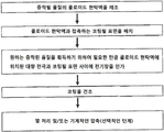
본 방법은 보다 구체적으로 다음의 연속적인 단계를 포함한다:The method more specifically comprises the following successive steps:
a) 애노드 층과 캐소드 층을 각 전도성 기판, 바람직하게는 금속 시트 또는 스트립 또는 금속화된 절연 시트 또는 스트립 또는 막 상에 각각 증착하는 단계 (여기서 상기 전도성 기판 또는 그 전도성 요소는 애노드와 캐소드의 전류 콜렉터로 각각 기능할 수 있다);a) depositing an anode layer and a cathode layer on each conductive substrate, preferably a metal sheet or strip or a metallized insulating sheet or strip or film, respectively, wherein the conductive substrate or its conductive element is the current between the anode and the cathode. Each can function as a collector);
b) 고체 전해질 층을 단계 a)에서 획득된 2개의 층들 중 적어도 하나 상에 증착하는 단계;b) depositing a solid electrolyte layer on at least one of the two layers obtained in step a);
c) Ms 접합 물질 층을 단계 a) 및/또는 b)에서 획득된 층들 중 적어도 하나 상에 증착하는 단계;c) depositing a layer of Ms bonding material on at least one of the layers obtained in steps a) and/or b);
d) 스택을 획득하기 위하여 단계 c)에서 획득된 층을 단계 a), b) 또는 c)에서 획득된 층과 면대면 스택하고, 배터리로 동작할 수 있는 기본 셀의 전-고체이고 원피스형의 다중층의 조립체를 획득하기 위하여 면대면 스택된 상기 2개의 층들 사이에 접촉을 촉진하는(promoting) 열 처리 및/또는 기계적인 압축을 수행하는 단계.d) To obtain a stack, the layer obtained in step c) is stacked face to face with the layer obtained in step a), b) or c), and is an all-solid, one-piece, battery-operated base cell. Performing a thermal treatment and/or mechanical compression promoting contact between the two layers stacked face to face to obtain a multi-layer assembly.
바람직하게는, 상기 애노드와 캐소드 층의 증착은 각 전도성 기판의 2개의 면 상에 수행된다.Preferably, the deposition of the anode and cathode layers is performed on two sides of each conductive substrate.
상기 Ms 접합 물질 층을 증착하는 것은 다음 기술들 중 하나에 의해 수행될 수 있다:Depositing the layer of the Ms bonding material can be performed by one of the following techniques:
i. 진공 증착 기술, 보다 구체적으로 물리적 증기 증착, 화학적 증기 증착, 또는 플라즈마-강화된 화학적 증기 증착;i. Vacuum deposition techniques, more specifically physical vapor deposition, chemical vapor deposition, or plasma-enhanced chemical vapor deposition;
ii. 졸-겔 증착 기술;ii. Sol-gel deposition technology;
iii. 현탁된 나노입자 증착 기술, 보다 구체적으로 잉킹(inking), 딥핑(dipping), 원심 분리(스핀-코팅) 및 랑뮤어-블로젯(Langmuir-Blodgett) 기술;iii. Suspended nanoparticle deposition technology, more specifically inking, dipping, centrifugation (spin-coating) and Langmuir-Blodgett technology;
iv. 전기 스프레이 기술;iv. Electric spray technology;
v. 에어로졸 증착 기술; 또는v. Aerosol deposition technology; or
vi. 전기 영동 증착 기술.vi. Electrophoretic deposition technology.
특정 실시예에 따라, 단계 a), b) 및 c)에서 획득된, 전기 영동에 의해 증착된 층들은 상기 층들이 증착 직후에 조밀하고 콤팩트할 수 없을 때 열 처리 및/또는 기계적인 압축에 의해 단계 d) 전에 고밀화될 수 있다.According to a specific embodiment, the layers deposited by electrophoresis, obtained in steps a), b) and c), are subjected to thermal treatment and/or mechanical compression when the layers cannot be dense and compact immediately after deposition. It can be densified before step d).
유리하게는, 고체 전해질 층이 단계 a)에서 획득된 2개의 층들 중 적어도 하나 상에 증착될 때, 단계 c)에서 획득된 Ms 접합 물질 층의 두께는 100 nm 미만, 바람직하게는 50 nm 미만, 훨씬 더 바람직하게는 30 nm 미만이다.Advantageously, when a solid electrolyte layer is deposited on at least one of the two layers obtained in step a), the thickness of the layer of Ms bonding material obtained in step c) is less than 100 nm, preferably less than 50 nm, Even more preferably less than 30 nm.
바람직한 실시예에서, 단계 d)의 스택의 기계적인 압축은 10 내지 100 MPa의 압력, 바람직하게는 20 내지 50 MPa의 압력에서 수행된다. 유사하게, 단계 d)의 열 처리는, 유리하게는, 바람직하게는, 상기 열 고밀화 단계를 받은 적어도 하나의 가장 융해가능한 Ms 접합 물질의 용융 또는 분해 온도(℃로 표현된)의 0.7 배를 초과하지 않는, 보다 바람직하게는, 용융 또는 분해 온도(℃로 표현된)의 0.5 배를 초과하지 않는, 훨씬 더 바람직하게는 0.3 배를 초과하지 않는 온도(TR)에서 수행된다.In a preferred embodiment, the mechanical compression of the stack of step d) is carried out at a pressure of 10 to 100 MPa, preferably at a pressure of 20 to 50 MPa. Similarly, the heat treatment in step d) advantageously exceeds 0.7 times the melting or decomposition temperature (expressed in °C) of the at least one most meltable Ms bonding material subjected to the thermal densification step. It is carried out at a temperature (T R ) that does not, more preferably does not exceed 0.5 times the melting or decomposition temperature (expressed in °C), even more preferably does not exceed 0.3 times.
상기 Ms 접합 물질은 다음 물질들 중 하나 이상으로부터 선택된다:The Ms bonding material is selected from one or more of the following materials:
a) Li3.6Ge0.6V0.4O4; Li2O-Nb2O5; LiSiO4; Li2O; Li14Zn(GeO4)4; Li0.35La0.55TiO3; Li0.5La0.5TiO3; Li7La3Zr2O12; Li5+xLa3(Zrx,A2-x)O12 (여기서 A=Sc, Ti, V, Y, Nb, Hf, Ta, Al, Si, Ga, Ge, Sn 및 1.4 ≤ x ≤ 2)로부터 선택된 산화물(oxide)-기반 물질;a) Li 3.6 Ge 0.6 V 0.4 O 4 ; Li 2 O-Nb 2 O 5 ; LiSiO 4 ; Li 2 O; Li 14 Zn(GeO 4 ) 4 ; Li 0.35 La 0.55 TiO 3 ; Li 0.5 La 0.5 TiO 3 ; Li 7 La 3 Zr 2 O 12 ; Li 5+x La 3 (Zr x, A 2-x )O 12 (where A=Sc, Ti, V, Y, Nb, Hf, Ta, Al, Si, Ga, Ge, Sn and 1.4 ≤ x ≤ 2 ) Oxide-based materials selected from;
b) Li3N; Li3PO4-xN2x/3, Li4SiO4-xN2x/3, Li4GeO4-xN2x/3 (여기서 0 < x < 4) 또는 Li3BO3-xN2x/3 (여기서 0 < x < 3)로부터 선택된 질화물(nitride)- 또는 옥시질화물-기반 물질; 실리콘(LiSiPON라고 지칭된다), 붕소(LiPONB라고 지칭된다), 황(LiPONS라고 지칭된다) 또는 알루미늄(LiPAON라고 지칭된다), 또는 알루미늄, 붕소, 황 및/또는 실리콘의 조합을 포함할 수 있는 리튬 및 인 (LiPON라고 지칭된다)의 옥시질화물-기반 물질; 실리콘(LiSiBON라고 지칭된다), 황(LiBONS라고 지칭된다) 또는 알루미늄(LiBAON라고 지칭된다), 또는 알루미늄, 황 및 실리콘의 조합을 포함할 수 있는 리튬 및 붕소(LiBON라고 지칭된다)의 옥시질화물-기반 물질; 및 보다 구체적으로 LixPOyNz (여기서 x ~ 2.8 및 2y = 3z, 0.16 ≤ z ≤ 0.46); 또는 LiwPOxNySz (여기서 (2x+3y+2z) = (5+w) 및 3.2 ≤ x ≤ 3.8; 0.13 ≤ y ≤ 0.4; 0 ≤ z ≤ 0.2; 2.9 ≤ w ≤ 3.3); 또는 LitPxAlyOuNvSw (여기서 (5x+3y)=5; (2u+3v+2w) = (5+t); 2.9 ≤ t ≤ 3.3; 0.84 ≤ x ≤ 0.94; 0.094 ≤ y ≤ 0.26; 3.2 ≤ u ≤ 3.8; 0.13 ≤ v ≤ 0.46; 0 ≤ w ≤ 0.2); 또는 Li1.9Si0.2P1.0O1.1N1.0; 또는 Li2.9PO3.3N0.46 유형의 물질;b) Li 3 N; Li 3 PO 4-x N 2x/3 , Li 4 SiO 4-x N 2x/3, Li 4 GeO 4-x N 2x/3 (where 0 <x <4) or Li 3 BO 3-x N 2x/ A nitride- or oxynitride-based material selected from 3 (where 0 <x <3); Lithium, which may include silicon (referred to as LiSiPON), boron (referred to as LiPONB), sulfur (referred to as LiPONS) or aluminum (referred to as LiPAON), or a combination of aluminum, boron, sulfur and/or silicon And oxynitride-based materials of phosphorus (referred to as LiPON); Oxynitrides of lithium and boron (referred to as LiBON), which may include silicon (referred to as LiSiBON), sulfur (referred to as LiBONS) or aluminum (referred to as LiBAON), or a combination of aluminum, sulfur and silicon- Base material; And more specifically Li x PO y N z (where x ~ 2.8 and 2y = 3z, 0.16≦z≦0.46); Or Li w PO x N y S z (where (2x+3y+2z) = (5+w) and 3.2≦x≦3.8; 0.13≦y≦0.4; 0≦z≦0.2; 2.9≦w≦3.3); Or Li t P x Al y O u N v S w (where (5x+3y)=5; (2u+3v+2w) = (5+t); 2.9 ≤ t ≤ 3.3; 0.84 ≤ x ≤ 0.94; 0.094 ≤ y ≤ 0.26; 3.2 ≤ u ≤ 3.8; 0.13 ≤ v ≤ 0.46; 0 ≤ w ≤ 0.2); Or Li 1.9 Si 0.2 P 1.0 O 1.1 N 1.0 ; Or a material of type Li 2.9 PO 3.3 N 0.46 ;
c) LixM1-yM'yS4 (여기서 M=Si, Ge, Sn 및 M'=P, Al, Zn, Ga, Sb); Li2S; B2S3; P2S5; 70Li2S-30P2S5; Li7P3S11; Li10GeP2S12; Li7PS6; Li3.25Ge0.25P0.75S4; Li10MP2S12 (여기서 M = Si, Ge, Sn) 및 Li2S와 P2S5, GeS2, Ga2S3 또는 SiS2 중에 있는 화합물 중 하나 사이의 혼합물로부터 선택된 황화물-기반 물질;c) Li x M 1-y M'y S 4 (where M=Si, Ge, Sn and M'=P, Al, Zn, Ga, Sb); Li 2 S; B 2 S 3 ; P 2 S 5 ; 70 Li 2 S-30P 2 S 5 ; Li 7 P 3 S 11 ; Li 10 GeP 2 S 12 ; Li 7 PS 6 ; Li 3.25 Ge 0.25 P 0.75 S 4 ; Li 10 MP 2 S 12 (where M = Si, Ge, Sn) and a sulfide-based material selected from a mixture between Li 2 S and one of the compounds in P 2 S 5 , GeS 2 , Ga 2 S 3 or SiS 2 ;
d) Li3PO4; LiTi(PO4)3; Li1+xAlxM2-x(PO4)3 (또는 M = Ge, Ti, 및/또는 Hf 및 0 < x < 1); Li1.3Al0.3Ti1.7(PO4)3; Li1+x+yAlxTi2-xSiyP3-yO12 (여기서 0 ≤ x ≤ 1 및 0 ≤ y ≤ 1); Li1+x+zMx (Ge1-yTiy)2-xSizP3-zO12 (여기서 0 ≤ x ≤ 0.8, 0 ≤ y ≤ 1.0, 0 ≤ z ≤ 0.6); 2(Li1.4Ti2Si0.4P2.6O12)-AlPO4; LixAlz-yGaySw(PO4)c 또는 LixAlz-yGaySw(BO3)c 또는 LixGez-ySiySw(PO4)c 또는 LixGez-ySiySw(BO3)c 또는 보다 일반적으로 LixMz-yM'ySw(PO4)c 또는 LixMz-yM'ySw(BO3)c (여기서 4 < w < 20, 3 < x < 10, 0 ≤ y ≤ 1 , 1 ≤ z ≤ 4 및 0 < c < 20, M 또는 M'는 Al, Si, Ge, Ga, P, Zn, Sb 중의 하나의 요소이다)로부터 선택된 인산염 또는 붕산염-기반 물질;d) Li 3 PO 4 ; LiTi(PO 4 ) 3 ; Li 1+x Al x M 2-x (PO 4 ) 3 (or M = Ge, Ti, and/or Hf and 0 <x <1); Li 1.3 Al 0.3 Ti 1.7 (PO 4 ) 3 ; Li 1+x+y Al x Ti 2-x Si y P 3 -y O 12 (where 0≦x≦1 and 0≦y≦1); Li 1+x+z Mx (Ge 1-y Ti y ) 2-x Si z P 3-z O 12 (where 0≦x≦0.8, 0≦y≦1.0, 0≦z≦0.6); 2(Li 1.4 Ti 2 Si 0.4 P 2.6 O 12 )-AlPO 4 ; Li x Al zy Ga y S w (PO 4 ) c or Li x Al zy Ga y S w (BO 3 ) c or Li x Ge zy Si y S w (PO 4 ) c or Li x Ge zy Si y S w (BO 3) c, or more generally, Li x M zy M 'y Sw (PO 4) c , or Li x M zy M' y Sw (BO 3) c ( where 4 <w <20, 3 < x <10, Phosphate or borate-based material selected from 0 ≤ y ≤ 1, 1 ≤ z ≤ 4 and 0 <c <20, M or M'is one of Al, Si, Ge, Ga, P, Zn, Sb) ;
e) Li2S와 Li3PO4, Li3PO4-xN2x/3, Li4SiO4-xN2x/3, Li4GeO4-xN2x/3 (여기서 0 < x < 4) 또는 Li3ΒO3-xN2x/3 (여기서 0 < x < 3) 중에 있는 화합물 중 하나 사이의 혼합물; Li2S 및/또는 B2S3 SiS2, P2S5, GeS2, Ga2S3와, 리튬 규산염(Li4SiO4), 리튬 붕산염(Li3BO3) 또는 리튬 인산염(Li3PO4)일 수 있는 LiaMOb 유형의 화합물 사이의 혼합물로부터 선택된 혼합된 물질.e) Li 2 S and Li 3 PO 4 , Li 3 PO 4 -x N 2x/3 , Li 4 SiO 4-x N 2x/3 , Li 4 GeO 4-x N 2x/3 (where 0 <x <4 ) Or a mixture between one of the compounds in Li 3 ΒO 3-x N 2x/3 (where 0 <x <3); Li 2 S and/or B 2 S 3 SiS 2 , P 2 S 5 , GeS 2 , Ga 2 S 3 with lithium silicate (Li 4 SiO 4 ), lithium borate (Li 3 BO 3 ) or lithium phosphate (Li 3 Mixed materials selected from mixtures between compounds of type Li a MO b , which may be PO 4 ).
일반적으로, 상기 Ms 접합 물질 입자의 사이즈 D50는 바람직하게는 100 nm 미만, 바람직하게는 50 nm 미만, 훨씬 더 바람직하게는 30 nm 미만이다. In general, the size D 50 of the Ms bonding material particles is preferably less than 100 nm, preferably less than 50 nm, and even more preferably less than 30 nm.
유리하게는, 상기 Ms 접합 물질은 리튬염에 함침된 적어도 하나의 폴리머를 포함하고 (또는 적어도 하나의 폴리머로 구성되고), 상기 폴리머는 바람직하게는 폴리에틸렌 산화물, 폴리이미드, 비닐리덴 폴리플루오라이드, 폴리아크릴로니트릴, 폴리메틸 메타크릴레이트, 폴리실록산에 의해 형성된 그룹으로부터 선택되고, 및 리튬염은 바람직하게는 LiCl, LiBr, LiI, Li(ClO4), Li(BF4), Li(PF6), Li(AsF6), Li(CH3CO2), Li(CF3SO3), Li(CF3SO2)2N, Li(CF3SO2)3, Li(CF3CO2), Li(B(C6H5)4), Li(SCN), Li(NO3)으로부터 선택된다.Advantageously, the Ms conjugation material comprises at least one polymer (or consists of at least one polymer) impregnated with a lithium salt, and the polymer is preferably polyethylene oxide, polyimide, vinylidene polyfluoride, Selected from the group formed by polyacrylonitrile, polymethyl methacrylate, polysiloxane, and the lithium salt is preferably LiCl, LiBr, LiI, Li(ClO 4 ), Li(BF 4 ), Li(PF 6 ) , Li(AsF 6 ), Li(CH 3 CO 2 ), Li(CF 3 SO 3 ), Li(CF 3 SO 2 ) 2 N, Li(CF 3 SO 2 ) 3 , Li(CF 3 CO 2 ), Li(B(C 6 H 5 ) 4 ), Li(SCN), Li(NO 3 ).
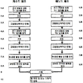
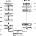
또한 본 발명은, 전-고체 배터리를 제조하는 방법으로서, 상기 배터리는 애노드 물질을 포함하는 적어도 하나의 층("애노드 층")을 포함하고, 고체 전해질 물질을 포함하는 적어도 하나의 층("전해질 층"), 및 캐소드 물질을 포함하는 적어도 하나의 층("캐소드 층")을 포함하고, 상기 3개의 층 각각은 전기 영동에 의해 증착되고, 상기 방법은 다음의 연속적인 단계를 포함한다:In addition, the present invention is a method of manufacturing an all-solid battery, wherein the battery includes at least one layer comprising an anode material ("anode layer"), and at least one layer comprising a solid electrolyte material ("electrolyte Layer"), and at least one layer comprising a cathode material ("cathode layer"), each of the three layers being deposited by electrophoresis, the method comprising the following successive steps:
a) 임의의 순서로, 애노드 층과 캐소드 층을 각 전도성 기판, 바람직하게는 금속 시트 또는 스트립 또는 금속화된 절연 시트 또는 스트립 또는 막 상에 각각 증착하는 단계(여기서 상기 전도성 기판 또는 그 전도성 요소는 각각 애노드와 캐소드의 전류 콜렉터로 기능할 수 있다);a) in any order, depositing an anode layer and a cathode layer on each conductive substrate, preferably a metal sheet or strip or metallized insulating sheet or strip or film, respectively, wherein the conductive substrate or conductive element Each can function as a current collector for anode and cathode);
b) 전해질 물질 입자의 현탁액으로부터 고체 전해질 층을 단계 a)에서 획득된 상기 애노드 층 및/또는 상기 캐소드 층 상에 증착하는 단계;b) depositing a solid electrolyte layer from a suspension of particles of electrolyte material on the anode layer and/or the cathode layer obtained in step a);
c) Ms 접합 물질 층을 다음 면 상에 증착하는 단계:c) depositing a layer of Ms bonding material on the next side:
i. 단계 a)에서 획득된 애노드 또는 캐소드 층의 면; 또는i. The side of the anode or cathode layer obtained in step a); or
ii. 단계 b)에서 획득된 전해질 층으로 커버된 상기 애노드 및/또는 캐소드 층의 면; 또는ii. The side of the anode and/or cathode layer covered with the electrolyte layer obtained in step b); or
iii. 단계 b)에서 획득된 전해질 층으로 커버된 상기 애노드 층의 면 및 단계 a)에서 획득된 상기 캐소드 층의 면 상에; 또는 단계 a)에 획득된 상기 애노드 층의 면 상에 및 단계 b)에서 획득된 전해질 층으로 커버된 상기 캐소드 층의 면 상에;iii. On the side of the anode layer covered with the electrolyte layer obtained in step b) and on the side of the cathode layer obtained in step a); Or on the side of the anode layer obtained in step a) and on the side of the cathode layer covered with the electrolyte layer obtained in step b);
d) 스택을 획득하기 위하여 단계 c)에서 획득된 층을 단계 a), b) 또는 c)에서 획득된 층과 면대면 스택하고, 배터리로 동작할 수 있는 스택된 다중층 구조 조립체를 획득하기 위하여 면대면 스택된 상기 2개의 층들 사이에 접촉을 촉진하는 열 처리 및/또는 기계적인 압축을 수행한다.d) stack the layer obtained in step c) face-to-face with the layer obtained in step a), b) or c) to obtain a stack, and to obtain a stacked multilayer structure assembly capable of operating as a battery A thermal treatment and/or mechanical compression is performed to facilitate contact between the two layers stacked face to face.
또한 본 발명은 본 발명에 따른 방법에 의해 제조될 수 있는 전-고체 배터리에 관한 것이다. 보다 구체적으로, 상기 배터리는 서로 병렬로 연결된 복수의 기본 셀의 조립체로 구성된다.The invention also relates to an all-solid battery that can be produced by the method according to the invention. More specifically, the battery is composed of an assembly of a plurality of basic cells connected in parallel with each other.
유리하게는, 상기 애노드 전류와 캐소드 전류의 전도성 기판은 귀금속으로 선택적으로 커버된 금속 시트, 또는 귀금속으로 선택적으로 커버된 폴리머 시트, 또는 귀금속으로 선택적으로 커버된 흑연 시트이다. 보다 구체적으로, 금속 시트 형태의 상기 애노드 전류와 캐소드 전류의 전도성 기판은 알루미늄 또는 구리이다. 보다 구체적으로, 폴리머 시트 형태의 상기 애노드 전류와 캐소드 전류의 전도성 기판은 다음 폴리머, 즉 폴리에틸렌 나프탈레이트(PEN), 폴리에틸렌 테레프탈레이트 (PET), 폴리프로필렌 (PP), 테프론![]()
![]()
![]()
![]()
유리하게는, 상기 귀금속은 다음 금속, 즉 금, 백금, 팔라듐, 바나듐, 코발트, 니켈, 망간, 니오븀, 탄탈륨, 크롬, 몰리브덴, 티타늄, 팔라듐, 지르코늄, 텅스텐 또는 이들 금속들 중 적어도 하나를 포함하는 임의의 합금으로부터 선택된다.Advantageously, the noble metal comprises at least one of the following metals: gold, platinum, palladium, vanadium, cobalt, nickel, manganese, niobium, tantalum, chromium, molybdenum, titanium, palladium, zirconium, tungsten or these metals. Selected from any alloy.
본 발명에 따른 배터리의 일 실시예에서, 상기 배터리는 적어도 하나의 캡슐 층, 바람직하게는 세라믹 또는 유리-세라믹 층을 포함한다. 유리하게는, 상기 배터리는 상기 제1 캡슐 층 상에 증착된 제2 캡슐 층을 포함하고, 상기 제2 층은 바람직하게는 실리콘 폴리머로 만들어진다.In one embodiment of the battery according to the invention, the battery comprises at least one encapsulating layer, preferably a ceramic or glass-ceramic layer. Advantageously, the battery comprises a second capsule layer deposited on the first capsule layer, and the second layer is preferably made of a silicon polymer.
유리하게는, 상기 배터리는 상기 캐소드와 애노드의 전류 콜렉터들을 볼 수 있는 단자들을 포함한다. 바람직하게는, 상기 애노드 연결과 캐소드 연결은 스택의 대향하는 측면들 상에 위치된다. 유리하게는, 상기 단자들은 또한 전기 화학 셀과 접촉하는 니켈 층으로 커버되고, 상기 니켈 층은 주석 층으로 커버된다.Advantageously, the battery comprises terminals through which current collectors of the cathode and anode are visible. Preferably, the anode and cathode connections are located on opposite sides of the stack. Advantageously, the terminals are also covered with a layer of nickel in contact with the electrochemical cell, the layer of nickel being covered with a layer of tin.
바람직하게는, 상기 적어도 하나의 캡슐 층은 상기 배터리의 6개의 면들 중 4개를 커버하고, 상기 2개의 다른 배터리 면은 단자로 커버된다.Preferably, the at least one capsule layer covers four of the six faces of the battery, and the two other battery faces are covered with terminals.
도 1a, 도 1b, 도 1c, 도 1d, 도 1e 및 도 1f은 본 발명에 따른 복수의 실시예에 따라 획득될 수 있는 제품을 도시하는 도면.
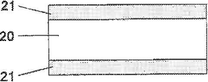
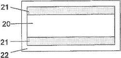
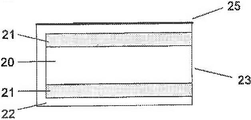
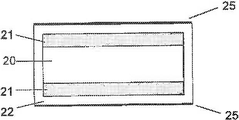
도 2는 전해질 층과 Ms 접합 물질 층으로 커버된 애노드와 캐소드의 스택을 도시하는 도면.
도 3은 본 발명의 실시예 중 하나에 따른 배터리의 조립체를 도시하는 도면.
도 4는 전기 영동 증착 방법의 일반적인 실시예를 도시하는 도면.
도 5a 및 도 5b는 본 발명에 따른 방법을 구현하는 디바이스를 개략적으로 도시하는 도면.
도 6 및 도 7은 본 발명의 2개의 상이한 실시예에 따른 배터리를 제조하는 단계를 개략적으로 도시하는 도면.
도 8은 전해질 층으로 커버된 캐소드 막(도면의 좌측)과 애노드 막(도면의 우측)을 개략적으로 도시하는 도면이고, 여기서 상기 2개의 막은 천공에 의해 컷아웃(cut out)된 패턴을 포함한다. 흑색 화살표는 전해질로 커버된 캐소드와 애노드 시트를 교대로 스택하는 동작을 도시하며, 그 컷아웃 패턴은 머리-꼬리 배열(head-to-tail configuration)로 스택된다.
도 9는 도 8에 도시된 스택으로부터 초래되는 전해질 층으로 커버된 캐소드와 애노드 시트를 스택하는 상세를 개략적으로 도시하는 도면.
도 10은 특정 실시예에 따라 본 발명에 따른 방법에 의해 획득될 수 있는 다중층 배터리를 도시하는 도면. 보다 구체적으로, 상기 다중층 배터리는, 다음 구성을 포함한다:
- 금속 시트, 또는 귀금속으로 커버된 금속 시트, 또는 귀금속으로 금속화된 폴리머 시트, 또는 귀금속으로 커버된 흑연 시트로 만들어진 복수의 기판 층(20);
- 복수의 고체 전해질 층(22);
- 복수의 얇은 애노드 층(21);
- 복수의 얇은 캐소드 층(24);
- 복수의 Ms 접합 물질 층(도면에는 미도시);
- 예를 들어, 산화물, 질화물, 인산염, 옥시질화물 또는 실록산 형태일 수 있는 폴리머, 세라믹 또는 유리-세라믹 물질로 구성될 수 있는 적어도 하나의 얇은 캡슐 층(37). 유리하게는, 이 캡슐 층은 에폭시 또는 실리콘 수지로 커버된 세라믹 또는 유리-세라믹 층을 포함한다;
- 단부들 각각에 양과 음의 전기적 연결을 교대로 사용할 수 있게 하는 단자(35, 36). 이들 단자는 상이한 배터리 요소들 사이에 전기적 연결을 병렬로 생성할 수 있게 한다. 이를 위해, 연결(+) 만이 일 단부에 남아 있고, (-)는 다른 단부에서 이용가능하다. 바람직하게는, 연결 (+) 및 (-)는 측방향으로 오프셋되고, 캡슐층은 상기 단부들에 단락이 존재하는 것을 방지하기 위해 유전체 물질로 기능한다. 상기 단자(35, 36)는 여기서 이중 층으로 도시되어 있으나 단일 층으로 제조될 수 있다.1A, 1B, 1C, 1D, 1E and 1F illustrate a product that can be obtained according to a plurality of embodiments according to the invention.
2 is a diagram showing a stack of anode and cathode covered with an electrolyte layer and a layer of Ms bonding material.
3 is a diagram showing an assembly of a battery according to one of the embodiments of the present invention.
4 is a diagram showing a general embodiment of an electrophoretic deposition method.
5a and 5b schematically show a device implementing the method according to the invention.
6 and 7 schematically show steps of manufacturing a battery according to two different embodiments of the present invention.
Fig. 8 is a diagram schematically showing a cathode film (left side of the figure) and an anode film (right side of the figure) covered with an electrolyte layer, wherein the two films comprise a pattern cut out by perforation. . The black arrows show the operation of alternately stacking the cathode and anode sheets covered with the electrolyte, and the cutout pattern is stacked in a head-to-tail configuration.
Fig. 9 schematically shows a detail of stacking a cathode and anode sheet covered with an electrolyte layer resulting from the stack shown in Fig. 8;
Fig. 10 shows a multilayer battery that can be obtained by the method according to the invention according to a specific embodiment. More specifically, the multilayer battery includes the following configuration:
-A plurality of substrate layers 20 made of a metal sheet, or a metal sheet covered with a noble metal, or a polymer sheet metalized with a noble metal, or a graphite sheet covered with a noble metal;
-A plurality of solid electrolyte layers 22;
-A plurality of thin anode layers 21;
-A plurality of thin cathode layers 24;
-A plurality of layers of Ms bonding material (not shown in the drawing);
-At least one
-Terminals (35, 36) allowing alternating positive and negative electrical connections to each of the ends. These terminals make it possible to create electrical connections in parallel between different battery elements. To this end, only the connection (+) remains at one end, and the (-) is available at the other end. Preferably, the connections (+) and (-) are laterally offset, and the encapsulation layer functions as a dielectric material to prevent the presence of a short at the ends. The
정의Justice
본 발명의 문맥에서, "전기 영동 증착" 또는 "전기 영동에 의한 증착"은 제일 먼저 액체 매질에 현탁된 입자를 바람직하게는 전도성 기판 상에 증착하는 방법에 의하여 증착된 층을 말하는데, 여기서 기판의 표면 쪽으로 입자가 움직이는 것은 현탁액에 놓인 2개의 전극들 사이에 전기장을 인가하는 것에 의해 형성되고, 이 전극들 중 하나는 증착이 수행되는 전도성 기판을 형성하고, 다른 전극 ("대향-전극")은 액체 상태에 놓여 있다. 아래에 설명되는 바와 같이 입자 현탁액의 제타 전위(zeta potential)가 적절한 값을 구비하는 경우, 및/또는 아래에 설명되는 바와 같이 특정 열적인 및/또는 기계적인 고밀화 처리 후에 소위 입자의 "조밀한" 증착물이 기판 상에 형성된다. 이 증착물은 임의의 다른 기술에 의해 획득된 증착과 본 증착물을 구별할 수 있는 이 기술 분야에 통상의 지식을 가진 자라면 인식할 수 있는 특정 구조물을 구비한다. In the context of the present invention, “electrophoretic deposition” or “electrophoretic deposition” refers to a layer deposited by a method of first depositing particles suspended in a liquid medium, preferably on a conductive substrate, wherein The movement of the particles toward the surface is formed by applying an electric field between two electrodes placed in the suspension, one of these electrodes forming a conductive substrate on which deposition is performed, and the other electrode ("counter-electrode") It lies in a liquid state. When the zeta potential of the particle suspension has an appropriate value, as described below, and/or after a certain thermal and/or mechanical densification treatment, the so-called "dense" of the particles, as described below. Deposits are formed on the substrate. This deposit has a specific structure recognizable to one of ordinary skill in the art that can distinguish the present deposit from the deposition obtained by any other technique.
본 문헌의 문맥에서 입자의 사이즈는 최대 크기이다. 따라서, "나노입자"는 크기들 중 적어도 하나는 100 nm 미만인 입자이다. 분말 또는 입자 그룹의 "입자 사이즈" 또는 "평균 입자 사이즈"는 D50으로 주어진다.In the context of this document the size of the particles is the largest. Thus, "nanoparticles" are particles in which at least one of the sizes is less than 100 nm. The “particle size” or “average particle size” of a powder or group of particles is given by D 50 .
현탁액의 "제타 전위"는 용액의 내부와 입자의 전단면(shear plane) 사이의 전위차로 정의된다. 이 전위는 현탁액의 안정성을 나타낸다. 이 전단면(또는 유체역학적 반경(hydrodynamic radius)은 입자가 용액에서 이동할 때 용매가 입자와 함께 이동하는 입자 주위의 가상의 구(imaginary sphere)에 대응한다. 제타 전위의 이론적인 기초와 결정은 전기 영동에 의한 증착물을 개발하는 전기화학자에 알려져 있고; 이 전위는 전기 영동 이동성으로부터 추론될 수 있다. 제타 전위를 직접 측정하기 위해 시판되는 여러 기술과 디바이스가 있다. 건조 추출물(extract)이 작을 때, 말버른사(Malvern company)의 제타사이저 나노 ZS(Zetasizer Nano ZS) 장비에 의하여 제타 전위를 측정할 수 있다. 이 장비는, 광 디바이스에 의하여, 입자에 인가되는 전기장의 함수로 입자의 변위 속도를 측정한다. 나아가, 광을 통과시키기 위하여 용액이 매우 희석될 필요가 있다. 건조 추출물이 더 많을 때, 예를 들어, 콜로이달 다이나믹스사(Colloidal Dynamics company)의 "어쿠스토사이저(acoustosizer)"라고 불리우는 디바이스를 사용하여 음파 영동(acoustophoresis) 기술에 의하여 제타 전위를 측정할 수 있다. 여기서 입자의 속도는 음향 기술에 의해 측정된다.The "zeta potential" of a suspension is defined as the difference in potential between the inside of the solution and the shear plane of the particle. This potential indicates the stability of the suspension. This shear plane (or hydrodynamic radius) corresponds to an imaginary sphere around a particle in which the solvent moves with the particle as the particle moves in solution. The theoretical basis of zeta potential and the determination is electricity. It is known to electrochemists who develop deposits by electrophoresis; this potential can be inferred from the electrophoretic mobility. There are several techniques and devices on the market to directly measure the zeta potential. When the dry extract is small, The zeta potential can be measured by the Malvern company's Zetasizer Nano ZS, which, by means of an optical device, measures the displacement velocity of the particle as a function of the electric field applied to the particle. Further, the solution needs to be very diluted in order to pass the light, when there is more dry extract, for example, the "acoustosizer" from the Colloidal Dynamics company. A device called a device can be used to measure the zeta potential by acoustophoresis technique, where the velocity of the particle is measured by acoustic technique.
"분산제"는 콜로이드 현탁액을 안정시키고 특히 입자들이 응집(agglomerating)하는 것을 방지할 수 있는 화합물을 말한다."Dispersant" refers to a compound that is capable of stabilizing a colloidal suspension and in particular preventing particles from agglomerating.
본 발명에 따른 "전-고체 다중층 배터리"는 복수의 "기본 셀"을 스택하고 조립하여 형성된 원피스형 배터리이다. 본 발명에서 "기본 셀"은 리튬 이온을 전도하는 고체 전해질에 의해 분리된 리튬 이온을 삽입한 애노드와 캐소드로 구성된 전기 화학 셀이다.The "all-solid multilayer battery" according to the present invention is a one-piece battery formed by stacking and assembling a plurality of "basic cells". In the present invention, the "basic cell" is an electrochemical cell composed of an anode and a cathode into which lithium ions separated by a solid electrolyte conducting lithium ions are inserted.
"전-고체" 배터리는 액체-상태 물질을 포함하지 않는 배터리이다. "Ms 접합 물질"은 상기 스택을 저온 열 처리 후 및/또는 기계적인 압축에 의하여 전-고체 다중층 배터리를 스택에 의해 형성하기 위하여, 상기 애노드 및 캐소드 층들 중 적어도 하나를 전해질 층으로 커버하고 열적으로 처리하고 및/또는 기계적으로 압축하여, 애노드 층과 캐소드 층을 조립시킬 수 있는 임의의 리튬 이온-전도성 물질을 말한다. 본 발명에 따라, 상기 Ms 접합 물질은 면대면 스택될 수 있는 전기 영동에 의해 증착된 2개의 면(층)들 중 적어도 하나 상에 증착된다.“All-solid” batteries are batteries that do not contain liquid-state materials. "Ms bonding material" covers at least one of the anode and cathode layers with an electrolyte layer in order to form an all-solid multilayer battery by the stack after low temperature heat treatment and/or by mechanical compression It refers to any lithium ion-conducting material that can be treated with and/or mechanically compressed to assemble the anode layer and the cathode layer. In accordance with the present invention, the Ms bonding material is deposited on at least one of two electrophoretically deposited sides (layers) that can be stacked face to face.
상세한 설명details
캐소드, 애노드 및 전해질 층을 전기 영동으로 증착하기 위한 콜로이드 현탁액("SP+", "SP-" 및 "SPn")의 준비Preparation of colloidal suspensions ("SP+", "SP-" and "SPn") for electrophoretic deposition of cathode, anode and electrolyte layers
완전히 균일한 두께를 가지고, 러프니스(roughness) 없이 적은 결함을 가지고 있고, 가능한 한 콤팩트한 증착물을 구비하기 위하여, 전기 영동 증착 방법의 결과, 증착물은 바람직하게는 매우 안정적인 콜로이드 현탁액(SP+, SP-, SPn)으로 수행된다. 현탁액의 안정성은 입자(P+, P-, Pn)의 사이즈 및 사용되는 용매에 의존하고 콜로이드 현탁액을 안정화시키는데 사용되는 안정제의 특성에 의존한다. "SP+"은 캐소드 층을 획득할 수 있게 하는 물질을 포함하는 입자("P+")의 콜로이드 현탁액을 말하고, "SP-"는 애노드 층을 획득할 수 있게 하는 물질의 입자(P-)을 포함하는 콜로이드 현탁액을 말하고, "SPn"은 전해질 층을 획득할 수 있게 하는 물질의 입자("Pn")의 콜로이드 현탁액을 말한다.In order to have a completely uniform thickness, have few defects without roughness, and have a deposit that is as compact as possible, as a result of the electrophoretic deposition method, the deposit is preferably a very stable colloidal suspension ( SP+, SP-). , SPn ). The stability of the suspension depends on the size of the particles ( P+, P-, Pn ) and the solvent used and on the properties of the stabilizer used to stabilize the colloidal suspension. " SP+ " refers to a colloidal suspension of particles (" P+ ") comprising a material that allows obtaining a cathode layer, and " SP- " includes particles of a material ( P- ) that enable obtaining an anode layer. Refers to a colloidal suspension, and " SPn " refers to a colloidal suspension of particles of a substance (" Pn ") that make it possible to obtain an electrolyte layer.
증착물의 가능한 후속 고밀화를 용이하게 하고 매우 정밀한 두께와 프로파일(러프니스)을 가지는 증착물을 제조하는 가능성을 보장하기 위해, 나노미터-사이즈의 입자를 포함하는 콜로이드 현탁액이 바람직하다. 이들 입자는 바람직하게는 100 nm 미만, 보다 바람직하게는 (특히 현탁액이 높은 용융점을 갖는 물질 입자를 가지는 경우) 30 nm 미만의 평균 입자 사이즈(D50)를 구비한다. 사실, 작은 입자로, 증착물을 고밀화하는 것은, 증착물이 콤팩트한 한, 매우 용이하게 된다.Colloidal suspensions comprising nanometer-sized particles are preferred to facilitate possible subsequent densification of the deposit and to ensure the possibility of producing deposits with very precise thickness and profile (roughness). These particles preferably have an average particle size (D 50 ) of less than 100 nm, more preferably less than 30 nm (especially if the suspension has material particles with a high melting point). In fact, with small particles, densifying the deposit becomes very easy, as long as the deposit is compact.
안정적인 콜로이드 현탁액으로부터 전기 영동 증착물을 제조하는 것은 증착물의 고밀화에 악영향을 미치는 다공, 공동 및 클러스터(cluster)의 형성을 회피할 수 있게 한다. 나아가, 이 기술로, 기계적인 프레스를 사용할 필요 없이 및 증착된 입자의 사이즈에 상관없이 우수한 콤팩트함을 가지는 증착물을 획득할 수 있다. 나아가, 증착된 입자의 사이즈가 작을 때, 즉 50 nm 미만의 입자 사이즈에 대해, 증착물의 고밀화는 열 처리를 요구함이 없이 건조할 때 시작할 수 있고; 특정 경우에는 증착물을 건조시키는 단계만으로도 충분할 수 있다.Preparing an electrophoretic deposit from a stable colloidal suspension makes it possible to avoid the formation of pores, cavities and clusters that adversely affect the densification of the deposit. Furthermore, with this technology, it is possible to obtain a deposited material having excellent compactness without the need to use a mechanical press and regardless of the size of the deposited particles. Furthermore, when the size of the deposited particles is small, i.e., for a particle size of less than 50 nm, the densification of the deposit can start when drying without requiring heat treatment; In certain cases, drying the deposit may be sufficient.
현탁액의 안정성은 제타 전위로 표현될 수 있다. 본 발명의 문맥에서, 현탁액은 제타 전위가 40 mV를 초과할 때 안정적이고, 60 mV를 초과할 때 매우 안정적인 것으로 고려된다. 그러나, 제타 전위가 20 mV 미만일 때, 입자 응집물(agglomerate)이 나타날 수 있다. 나아가, 층에 우수한 콤팩트함을 보장하기 위하여, 증착물은, 일부 실시예에서, (절대 값으로) 40 mV를 초과하는 제타 전위를 가지는 콜로이드 현탁액으로 제조된다. 그러나, 다른 바람직한 실시예에서 본 발명의 문맥에서, 현탁액은 적은 건조 입자 추출물을 가지고 있고, 제타 전위는 아래에 보다 상세히 설명된 바와 같이 40 mV 미만이다.The stability of the suspension can be expressed as the zeta potential. In the context of the present invention, suspensions are considered to be stable when the zeta potential exceeds 40 mV and very stable when the zeta potential exceeds 60 mV. However, when the zeta potential is less than 20 mV, particle agglomerates may appear. Furthermore, in order to ensure good compactness in the layer, the deposits are, in some embodiments, prepared as colloidal suspensions with a zeta potential in excess of 40 mV (absolute value). However, in the context of the present invention in another preferred embodiment, the suspension has less dry particle extract and the zeta potential is less than 40 mV, as explained in more detail below.
전기 영동에 사용되도록 의도된 콜로이드 현탁액은 유기 용매 또는 탈염수(demineralized water) 또는 용매 혼합물일 수 있는 전기 절연 용매와 증착될 입자를 포함한다.Colloidal suspensions intended for use in electrophoresis contain particles to be deposited with an electrically insulating solvent, which may be an organic solvent or demineralized water or solvent mixture.
안정적인 현탁액에서, 입자들이 서로 응집하지 않아 증착물에 공동을 제조할 수 있는 클러스터, 응집물 및/또는 상당한 결함을 형성할 수 있다. 입자들은 현탁액에서 격리된 채 유지된다.In a stable suspension, the particles do not agglomerate with each other and can form clusters, agglomerates and/or significant defects that can create cavities in the deposit. The particles remain isolated from the suspension.
나아가, 본 발명의 일 실시예에서, 콤팩트한 증착물을 획득하는데 필요한 현탁액의 안정성은 안정제를 추가하는 것에 의해 획득된다. 안정제는 분말이 응집되는 것과 응집물이 형성되는 것을 방지할 수 있게 한다. 이것은 정전 효과(electrostatic effect), 입체 효과(steric effect)에 의해 또는 이 2개의 효과의 조합에 의해 작용할 수 있다. 정전 안정은 현탁된 나노입자들 사이에 정전 반발의 배치에 기초한다.Furthermore, in one embodiment of the present invention, the stability of the suspension required to obtain a compact deposit is obtained by adding a stabilizer. Stabilizers make it possible to prevent the powder from agglomeration and the formation of agglomerates. This can act by an electrostatic effect, a stereo effect, or a combination of the two effects. Electrostatic stability is based on the placement of electrostatic repulsion between the suspended nanoparticles.
정전 안정(electrostatic stabilization)은 입자의 표면 전하에 의해 제어된다; 이 정전 안정은 그 결과 pH에 의존할 수 있다. 입체 안정(steric stabilization)은, 현탁액에 추가되어 입자의 표면에 흡수되어 상호 특정 공간의 밀집(congestion)에 의해 반발을 야기하는 폴리머 비-이온 계면활성제 또는 심지어 단백질을 사용한다. 이 2개의 안정 메커니즘의 조합이 또한 가능하다. 본 발명의 문맥에서, 정전 안정이 입체 안정에 비해 바람직하다. 정전 안정은 구현하기 용이하고, 가역적이고, 저렴하고 또 후속 응고(consolidation) 공정을 용이하게 한다.Electrostatic stabilization is controlled by the surface charge of the particle; This electrostatic stability can as a result depend on the pH. Steric stabilization uses polymeric non-ionic surfactants or even proteins that are added to the suspension and are absorbed by the surface of the particles and cause repulsion by congestion of mutually specific spaces. A combination of these two stabilization mechanisms is also possible. In the context of the present invention, electrostatic stability is preferred over steric stability. Electrostatic stability is easy to implement, reversible, inexpensive and facilitates the subsequent consolidation process.
그러나, 본 발명자는, 본 발명의 문맥에서 사용된 배터리 물질의 나노 입자를 통해, 안정제를 추가함이 없이, 서로 응집하지 않은 입자의 안정적인 콜로이드 현탁액 및/또는 수 개의 입자의 응집물을 획득할 수 있다는 것을 발견하였다. 입자 및/또는 응집물은 바람직하게는 100 nm 미만, 보다 바람직하게는 50 nm 미만의 사이즈를 구비한다.However, the inventors have found that, through the nanoparticles of the battery material used in the context of the present invention, it is possible to obtain a stable colloidal suspension of particles not agglomerated with each other and/or agglomerates of several particles without adding a stabilizer. Found it. The particles and/or aggregates preferably have a size of less than 100 nm, more preferably less than 50 nm.
이들 현탁액은 일반적으로 2 g/L 내지 20 g/L, 바람직하게는 3 내지 10 g/L의 적은 건조 추출물과, 보다 구체적으로 액체 알코올 상태, 바람직하게는 에탄올 및/또는 세톤(cetone), 바람직하게는 아세톤에서 4 g/L 정도의 건조 추출물에 대해 획득되었다. 안정제를 추가함이 없는 이들 안정적인 콜로이드 입자 현탁액이 본 발명의 문맥에서 특히 선호된다.These suspensions are generally in the form of a small dry extract of 2 g/L to 20 g/L, preferably 3 to 10 g/L, more specifically in a liquid alcohol state, preferably ethanol and/or cetone, preferably It was obtained for a dry extract of about 4 g / L in acetone. These stable colloidal particle suspensions without the addition of a stabilizer are particularly preferred in the context of the present invention.
이러한 현탁액의 제타 전위는 일반적으로 40 mV 미만, 보다 구체적으로 25 내지 40 mV이다. 이것은 이러한 현탁액이 불안정한 경향이 있다는 것을 의미할 수 있으나; 본 발명자는 전기 영동 증착을 위해 이들 현탁액을 사용하면 매우 고품질의 증착된 층을 초래할 수 있다는 것을 관찰하였다.The zeta potential of these suspensions is generally less than 40 mV, more specifically 25 to 40 mV. This could mean that these suspensions tend to be unstable; The inventors have observed that using these suspensions for electrophoretic deposition can result in very high quality deposited layers.
비-휘발성 유기 안정제는 나노입자의 전기 절연을 초래하여, 임의의 전기 화학 응답을 방지할 수 있다.Non-volatile organic stabilizers can result in electrical insulation of the nanoparticles, preventing any electrochemical response.
물이 용매로 사용될 때, 5 V 미만의 증착 전압이 바람직하다. 사실, 5 V를 넘으면, 물은 전기 분해될 위험이 있어서, 전극 상에 가스를 생성할 수 있어서, 증착물을 다공성으로 만들고 기판에의 부착력을 감소시킬 수 있다. 나아가, 수성 매질(aqueous medium)에서 갈바닉 반응은 증착물을 오염시킬 수 있는 금속 카티온(cation)을 형성할 수 있다.When water is used as the solvent, a deposition voltage of less than 5 V is preferred. In fact, above 5 V, there is a risk that the water will be electrolyzed, which can create a gas on the electrode, making the deposit porous and reducing adhesion to the substrate. Furthermore, galvanic reactions in an aqueous medium can form metal cations that can contaminate the deposit.
바람직한 실시예에서, 증착물은 용매 상태로 제조된다. 이것은 더 높은 전압 값에서 동작하여, 증착 속도(deposition rate)를 증가시킬 수 있다.In a preferred embodiment, the deposit is prepared in a solvent state. It can operate at higher voltage values, increasing the deposition rate.
본 발명에 따라, 캐소드 층을 제조하는데 사용되는 나노입자는 다음 물질들 중 하나 이상으로부터 선택되는 것이 바람직하지만, 완전히 그러한 것은 아니다:According to the present invention, the nanoparticles used to prepare the cathode layer are preferably selected from one or more of the following materials, but not entirely:
(i) 산화물: LiMn2O4, LiCoO2, LiNiO2, LiMn1.5Ni0.5O4, LiMn1.5Ni0.5-xXxO4 (여기서 X는 Al, Fe, Cr, Co, Rh, Nd, 다른 희토류 원소로부터 선택되고, 0 < x < 0.1), LiFeO2, LiMn1/3N1/3Co1/3O4;(i) Oxide: LiMn 2 O 4 , LiCoO 2 , LiNiO 2 , LiMn 1.5 Ni 0.5 O 4 , LiMn 1.5 Ni 0.5-x X x O 4 (where X is Al, Fe, Cr, Co, Rh, Nd, other Selected from rare earth elements, 0 <x <0.1), LiFeO 2 , LiMn 1/3 N 1/3 Co 1/3 O 4 ;
(ii) 인산염: LiFePO4, LiMnPO4, LiCoPO4, LiNiPO4, Li3V2(PO4)3;(ii) Phosphate: LiFePO 4 , LiMnPO 4 , LiCoPO 4 , LiNiPO 4 , Li 3 V 2 (PO 4 ) 3 ;
(iii) 다음과 같은 칼코게나이드(chalcogenide): V2O5, V3O8, TiS2, TiOySz, WOySz, CuS, CuS2의 모든 리튬화된 형태(lithiated form). (iii) The following chalcogenides: V 2 O 5 , V 3 O 8 , TiS 2 , TiO y S z , WO y S z , all lithiated forms of CuS, CuS 2 .
본 발명에 따라, 애노드 층을 제조하는데 사용되는 나노입자는 다음 물질들 중 하나 이상으로부터 선택되는 것이 바람직하지만, 완전히 그러한 것은 아니다:In accordance with the present invention, the nanoparticles used to make the anode layer are preferably selected from one or more of the following materials, but not entirely:
(i) 주석 옥시질화물(일반식 SnOxNy);(i) tin oxynitride (general formula SnO x N y );
(ii) 혼합된 실리콘 및 주석 옥시질화물(일반식 SiaSnbOyNz, 여기서 a>0, b>0, a+b≤2, 0<y≤4, 0<z≤3 (SiTON라고도 지칭된다), 및 특히 SiSn0.87O1.2N1.72); 및 SiaSnbCcOyNz 형태의 옥시질화물(여기서 a>0, b>0, a+b≤2, 0<c-10, 0<y<24, 0<z<17); SiaSnbCcOyNzXn 및 SiaSnbOyNzXn (여기서 Xn는 F, Cl, Br, I, S, Se, Te, P, As, Sb, Bi, Ge, Pb 중 적어도 하나의 요소이다). (ii) Mixed silicon and tin oxynitride (general formula Si a Sn b O y N z , where a>0, b>0, a+b≤2, 0<y≤4, 0<z≤3 (SiTON Also referred to as), and in particular SiSn 0.87 O 1.2 N 1.72 ); And an oxynitride in the form of Si a Sn b C c O y N z (where a>0, b>0, a+b≦2, 0<c-10, 0<y<24, 0<z<17); Si a Sn b C c O y N z X n and Si a Sn b O y N z X n (where Xn is F, Cl, Br, I, S, Se, Te, P, As, Sb, Bi, Ge , Pb is at least one element).
(iii) SixNy (특히 x=3 및 y=4), SnxNy (특히 x=3 및 y=4), ZnxNy (특히 x=3 및 y=4), Li3-XMXN (여기서 M = Co, Ni, Cu) 유형의 질화물;(iii) Si x N y (especially x=3 and y=4), Sn x N y (especially x=3 and y=4), Zn x N y (especially x=3 and y=4), Li 3 -X M X N (where M = Co, Ni, Cu) type nitride;
(iv) 산화물 SnO2, Li4Ti5O12, SnB0.6P0.4O2.9.(iv) Oxide SnO 2 , Li 4 Ti 5 O 12 , SnB 0.6 P 0.4 O 2.9 .
애노드 층을 제조하는데 Li4Ti5O12 나노입자가 보다 구체적으로 바람직하다.Li 4 Ti 5 O 12 nanoparticles are more specifically preferred for preparing the anode layer.
애노드 또는 캐소드를 제조하기 위하여, 전해질 층을 제조하는데 사용되는 유형의 전기 전도성 물질의 나노입자, 특히 흑연 및/또는 리튬 이온 전도성 물질의 나노입자를 전술된 물질에 추가할 수 있다. 사실, 특정 전극 물질은 불량한 이온 및 전기 전도체이다. 그 결과, 이들 물질은 3 μm를 초과하는 두께로 증착될 때, 전극은 너무 저항적일 수 있다. 우수한 에너지 밀도를 갖는 배터리를 제공하기 위하여 1 내지 10 μm의 두께는 일반적으로 전극에 바람직하다. 이 경우에, 전극 물질 입자와 (이온 및/또는 전기) 전도성 입자의 공동 증착물을 제조하는데 필요하다.To prepare the anode or cathode, nanoparticles of an electrically conductive material of the type used to prepare the electrolyte layer, in particular nanoparticles of graphite and/or lithium ion conductive material, can be added to the above-described material. In fact, certain electrode materials are poor ionic and electrical conductors. As a result, when these materials are deposited to a thickness exceeding 3 μm, the electrode may be too resistive. A thickness of 1 to 10 μm is generally preferred for the electrode to provide a battery with good energy density. In this case, it is necessary to make a co-deposit of electrode material particles and (ionic and/or electrically) conductive particles.
전해질은 우수한 이온 전도체이어야 하지만 또한 전기 절연체이어야 한다. 본 발명에 따라, 전해질 층을 제조하는데 사용되는 나노입자는 바람직하게는 다음 물질들 중 하나 이상으로부터 선택된다:The electrolyte must be a good ion conductor, but it must also be an electrical insulator. According to the invention, the nanoparticles used to prepare the electrolyte layer are preferably selected from one or more of the following materials:
a) Li3.6Ge0.6,6V0.4O4; Li2O-Nb2O5; LiSiO4; Li2O; Li14Zn(GeO4)4; Li0.35La0.55TiO3; Li0.5La0.5TiO3; Li7La3Zr2O12; Li5+xLa3(Zrx,A2-x)O12 (여기서 A=Sc, Ti, V, Y, Nb, Hf, Ta, Al, Si, Ga, Ge, Sn 및 1.4 ≤ x ≤ 2)로부터 선택된 산화물-기반 물질;a) Li 3.6 Ge 0.6 , 6V 0.4 O 4 ; Li 2 O-Nb 2 O 5 ; LiSiO 4 ; Li 2 O; Li 14 Zn(GeO 4 ) 4 ; Li 0.35 La 0.55 TiO 3 ; Li 0.5 La 0.5 TiO 3 ; Li 7 La 3 Zr 2 O 12 ; Li 5+x La 3 (Zr x ,A 2-x )O 12 (where A=Sc, Ti, V, Y, Nb, Hf, Ta, Al, Si, Ga, Ge, Sn and 1.4 ≤ x ≤ 2 ) Oxide-based materials selected from;
b) Li3N; Li3PO4-xN2x/3, Li4SiO4-xN2x/3, Li4GeO4-xN2x/3 (여기서 0 < x < 4) 또는 Li3BO3-xN2x/3 (여기서 0 < x < 3)로부터 선택된 질화물 또는 옥시질화물-기반 물질; 실리콘 (LiSiPON), 붕소 (LiPONB) 또는 황 (LiPONS) 또는 알루미늄 (LiPAON), 또는 알루미늄, 붕소, 황 및/또는 실리콘의 조합을 포함할 수 있는 리튬 및 인의 옥시질화물-기반 물질 (LiPON라고 지칭된다); 실리콘 (LiSiBON), 황 (LiBONS) 또는 알루미늄 (LiBAON), 또는 알루미늄, 황 및 실리콘의 조합을 포함할 수 있는 리튬 및 붕소의 옥시질화물-기반 물질 (LiBON라고 지칭된다); 및 보다 구체적으로 LixPOyNz (여기서 x ~2.8 및 2y = 3z , 0.16 ≤ z ≤ 0.46); 또는 LiwPOxNySz (여기서 (2x+3y+2z) = (5+w) 및 3.2 ≤ x ≤ 3.8; 0.13 ≤ y ≤ 0.4; 0 ≤ z ≤ 0.2; 2.9 ≤ w ≤ 3.3); 또는 LitPxAlyOuNvSw (여기서 (5x+3y) = 5; (2u+3v+2w) = (5+t); 2.9 ≤ t≤ 3.3; 0.84 ≤ x ≤ 0.94; 0.094 ≤ y ≤ 0.26; 3.2 ≤ u ≤ 3.8; 0.13 ≤ v ≤ 0.46; 0 ≤ w ≤ 0.2); 또는 Li1.9Si0.2P1.0O1.1N1.0; 또는 Li2.9PO3.3N0.46 유형의 물질; b) Li 3 N; Li 3 PO 4-x N 2x/3 , Li 4 SiO 4-x N 2x/3 , Li 4 GeO 4-x N 2x/3 (where 0 <x <4) or Li 3 BO 3-x N 2x/ A nitride or oxynitride-based material selected from 3 , wherein 0 <x <3; Oxynitride-based materials of lithium and phosphorus (LiPON), which may include silicon (LiSiPON), boron (LiPONB) or sulfur (LiPONS) or aluminum (LiPAON), or combinations of aluminum, boron, sulfur and/or silicon. ); Oxynitride-based materials of lithium and boron (referred to as LiBON), which may include silicon (LiSiBON), sulfur (LiBONS) or aluminum (LiBAON), or combinations of aluminum, sulfur and silicon; And more specifically Li x PO y N z (where x ~ 2.8 and 2y = 3z, 0.16≦z≦0.46); Or Li w PO x N y S z (where (2x+3y+2z) = (5+w) and 3.2≦x≦3.8; 0.13≦y≦0.4; 0≦z≦0.2; 2.9≦w≦3.3); Or Li t P x Al y O u N v S w (where (5x+3y) = 5; (2u+3v+2w) = (5+t); 2.9 ≤ t ≤ 3.3; 0.84 ≤ x ≤ 0.94; 0.094 ≤ y ≤ 0.26; 3.2 ≤ u ≤ 3.8; 0.13 ≤ v ≤ 0.46; 0 ≤ w ≤ 0.2); Or Li 1.9 Si 0.2 P 1.0 O 1.1 N 1.0 ; Or a material of type Li 2.9 PO 3.3 N 0.46 ;
c) LixM1-yM'yS4 (여기서 M=Si, Ge, Sn 및 M'=P, Al, Zn, Ga, Sb); Li2S; B2S3; P2S5; 70Li2S-30P2S5; Li7P3S11; Li10GeP2Si12; Li7PS6; Li3.25Ge0.25P0.75S4; Li10MP2Si12 (여기서 M = Si, Ge, Sn), 및 Li2S와 P2S5, GeS2, Ga2S3 또는 SiS2 중에 있는 하나의 화합물 사이의 혼합물로부터 선택된 황화물-기반 물질;c) Li x M 1-y M'y S 4 (where M=Si, Ge, Sn and M'=P, Al, Zn, Ga, Sb); Li 2 S; B 2 S 3 ; P 2 S 5 ; 70 Li 2 S-30P 2 S 5 ; Li 7 P 3 S 11 ; Li 10 GeP 2 Si 12 ; Li 7 PS 6 ; Li 3.25 Ge 0.25 P 0.75 S 4 ; Li 10 MP 2 Si 12 (where M = Si, Ge, Sn), and a sulfide-based mixture selected from a mixture between Li 2 S and one compound in P 2 S 5 , GeS 2 , Ga 2 S 3 or SiS 2 matter;
d) Li3PO4; LiTi(PO4)3; Li1+xAlxM2-x(PO4)3 (또는 M = Ge, Ti, 및/또는 Hf 및 0 < x < 1); Li1.3Al0.3Ti1.7(PO4)3; Li1+x+yAlxTi2-xSiyP3-yO12 (여기서 0 ≤ x ≤ 1 및 0 ≤ y ≤ 1 ); Li1+x+zMx(Ge1-yTiy)2-xSizP3-zO12 (여기서 0 ≤ x ≤ 0.8, 0 ≤ y ≤ 1.0, 0 ≤ z ≤ 0.6); 2(Li1.4Ti2Si0.4P2.6O12)-AlPO4; LixAlz-yGaySw(PO4)c 또는; LixAlz-yGaySw(BO3)c 또는 LixGez-ySiySw(PO4)c 또는; LixGez-ySiySw(BO3)c 또는 보다 일반적으로 LixMz-yM'ySw(PO4)c 또는 LixMz-yM'ySw(BO3)c (여기서 4 < w < 20, 3 < x < 10, 0 ≤ y ≤ 1, 1 ≤ z ≤ 4 및 0 < c < 20, M 또는 M'는 Al, Si, Ge, Ga, P, Zn, Sb 중 하나의 요소이다)로부터 선택된 인산염 또는 붕산염-기반 물질;d) Li 3 PO 4 ; LiTi(PO 4 ) 3 ; Li 1+x Al x M 2-x (PO 4 ) 3 (or M = Ge, Ti, and/or Hf and 0 <x <1); Li 1.3 Al 0.3 Ti 1.7 (PO 4 ) 3 ; Li 1+x+y Al x Ti 2-x Si y P 3-y O 12 (where 0≦x≦1 and 0≦y≦1); Li 1+x+z Mx(Ge 1-y Ti y ) 2-x Si z P 3-z O 12 (where 0≦x≦0.8, 0≦y≦1.0, 0≦z≦0.6); 2(Li 1.4 Ti 2 Si 0.4 P 2.6 O 12 )-AlPO 4 ; Li x Al zy Ga y S w (PO 4 ) c or; Li x Al zy Ga y S w (BO 3 ) c or Li x Ge zy Si y S w (PO 4 ) c or; Li x Ge zy Si y S w (BO 3) c, or more generally, Li x M zy M 'y S w (PO 4) c, or Li x M zy M' y S w (BO 3) c ( where 4 < w <20, 3 <x <10, 0 ≤ y ≤ 1, 1 ≤ z ≤ 4 and 0 <c <20, M or M'is one of Al, Si, Ge, Ga, P, Zn, Sb A phosphate or borate-based material selected from;
e) Li2S와 Li3PO4, Li3PO4-xN2x/3, Li4SiO4-xN2x/3, Li4Ge04-xN2x/3 (여기서 0 < x < 4) 또는 Li3BO3-xN2x/3 (여기서 0 < x < 3) 중에 있는 하나의 화합물 사이의 혼합물; Li2S 및/또는 B2S3, SiS2, P2S5, GeS2, Ga2S3와, 리튬 규산염(Li4SiO4), 리튬 붕산염(Li3BO3) 또는 리튬 인산염(Li3PO4)일 수 있는 LiaMOb 유형의 화합물 사이의 혼합물로부터 선택된 혼합된 물질.e) Li 2 S and Li 3 PO 4 , Li 3 PO 4 -x N 2x/3 , Li 4 SiO 4-x N 2x/3 , Li 4 Ge0 4-x N 2x/3 (where 0 <x <4 ) Or a mixture between one compound in Li 3 BO 3-x N 2x/3 (where 0 <x <3); Li 2 S and/or B 2 S 3 , SiS 2 , P 2 S 5 , GeS 2 , Ga 2 S 3 with lithium silicate (Li 4 SiO 4 ), lithium borate (Li 3 BO 3 ) or lithium phosphate (Li 3 PO 4 ) Mixed material selected from mixtures between compounds of type Li a MO b which may be.
원하는 타깃 화학적 조성이 한정되었다면, 즉 분말 또는 분말 혼합물의 특성이 한정되었다면, 나노입자는 적절한 액체 상태로 현탁된다. 특정 실시예에서, 제타 전위가 바람직하게는 40 mV를 초과하는 현탁액을 획득하기 위하여 안정제가 추가된다.If the desired target chemical composition has been defined, ie the properties of the powder or powder mixture have been defined, the nanoparticles are suspended in an appropriate liquid state. In certain embodiments, a stabilizer is added to obtain a suspension with a zeta potential of preferably greater than 40 mV.
그러나, 유리하게는, 안정제를 전혀 포함하지 않거나 거의 포함하지 않는 (<10 ppm) 현탁액과, 특히 적은 건조 추출물(일반적으로 20 g/L 미만, 바람직하게는 10 g/l 미만)을 구비하는 현탁액과, 특히 100 nm 미만, 바람직하게는 50 nm 미만의 사이즈를 구비하는 입자를 포함하는 현탁액이 사용된다. 이 경우에, 현탁액의 제타 전위는 일반적으로 25 내지 40 mV이다.However, advantageously, suspensions containing little or no stabilizers (<10 ppm) and especially with little dry extract (generally less than 20 g/L, preferably less than 10 g/l) And, in particular, suspensions comprising particles having a size of less than 100 nm, preferably less than 50 nm are used. In this case, the zeta potential of the suspension is generally 25 to 40 mV.
일례로서, 사용된 용매는 세톤, 알코올 또는 이들 둘의 혼합물에 기초할 수 있다.As an example, the solvent used may be based on cetone, alcohol or a mixture of both.
사용될 수 있는 입체 안정제 중에, 선택된 유기 용매에 용해가능한 조건에서 특히 폴리에틸렌 이민(PEI), 폴리아크릴산(PAA), 구연산, 니트로셀룰로스 또는 아세틸아세톤을 언급할 수 있다.Among the steric stabilizers that can be used, mention may be made of polyethylene imine (PEI), polyacrylic acid (PAA), citric acid, nitrocellulose or acetylacetone, in particular under conditions soluble in the selected organic solvent.
정전 안정은 요오드화물, 산 또는 염기를 추가하는 것에 의해 수행될 수 있다.Electrostatic stabilization can be accomplished by adding iodide, acid or base.
현탁액의 전기 전도율은 2개의 전극들 사이에 높은 전위 구배를 획득하기 위하여 제어될 수 있다. 바람직하게는, 콜로이드 현탁액의 전도율은 1 내지 20 μS/cm이다. 약성이든 강성이든 간에 산 및 염기는 적은 양이 추가되어 현탁액의 전도율을 제어하고 입자 표면을 대전시킬 수 있다.The electrical conductivity of the suspension can be controlled to obtain a high potential gradient between the two electrodes. Preferably, the conductivity of the colloidal suspension is 1 to 20 μS/cm. Small amounts of acids and bases, whether weak or rigid, can be added in small amounts to control the conductivity of the suspension and charge the particle surface.
안정적인 현탁액을 획득하기 위하여, 응집 없이 나노미터-사이즈의 입자로, 현탁 전에, 분말을 그라인드(grinding)하고 및/또는 분산하는 단계를 수행하여 입자를 응집 해제(de-agglomerate)하고 그 사이즈를 조절하고 (100 nm 미만 또는 심지어 30 nm 미만의 평균 사이즈를 획득하고), 사이즈 분산(dispersion)을 감소시키는 것이 필요할 수 있다. 입자의 응집 해제와 현탁을 도와주기 위하여 초음파를 더 사용할 수 있다.To obtain a stable suspension, a step of grinding and/or dispersing the powder into nanometer-sized particles without agglomeration, prior to suspension, is performed to de-agglomerate the particles and adjust their size. And (to obtain an average size of less than 100 nm or even less than 30 nm), it may be necessary to reduce the size dispersion. Ultrasound can be used to further aid in deagglomeration and suspension of particles.
분산 그라인드 단계 동안 입자에 형성된 결함은 또한 기계적인 압축을 수행할 때와 같이 고밀화 온도를 감소시킬 수 있다.Defects formed in the particles during the dispersion grinding step can also reduce the densification temperature, such as when performing mechanical compression.
전기 영동에 의한 애노드, 캐소드 및 고체 전해질 층의 증착Deposition of anode, cathode and solid electrolyte layers by electrophoresis
본 발명에 따라, 애노드, 캐소드 및 고체 전해질은 모두 전기 영동 수단에 의해 증착된다. 입자의 전기 영동 증착은 증착이 수행되는 기판과 대향-전극 사이에 전기장을 인가하여, 콜로이드 현탁액의 대전된 입자를 이동시켜, 기판에 증착시키는 것에 의해 수행된다. 입자를 표면에 증착하는 바인더 및 다른 용매가 없으면 매우 콤팩트한 증착물을 획득할 수 있게 한다. 전기 영동 증착에 의해 획득된 콤팩트함은 건조 단계 동안 증착물에 다른 결함이 나타나거나 크랙의 위험을 제한하거나 심지어 방지한다. 그러나, 두꺼운 증착물을 제조하기 위하여, 연속적인 증착/건조 단계를 구현하는 것이 고려될 수 있다. 유기 화합물이 없으면 우발적으로 단락된 경우에 배터리가 연소할 위험을 감소시킨다.According to the invention, the anode, cathode and solid electrolyte are all deposited by means of electrophoresis. The electrophoretic deposition of particles is carried out by applying an electric field between the substrate on which the deposition is performed and the counter-electrode to move the charged particles of the colloidal suspension to deposit on the substrate. The absence of binders and other solvents for depositing the particles on the surface makes it possible to obtain very compact deposits. The compactness obtained by electrophoretic deposition limits or even prevents the risk of cracking or the appearance of other defects in the deposit during the drying step. However, in order to produce thick deposits, it may be considered to implement a continuous deposition/drying step. The absence of organic compounds reduces the risk of battery burning in case of accidental short circuit.
나아가, 전기 영동에 의해 획득된 증착물은 바인더 또는 다른 유기 화합물을 포함하지 않으므로, 본 발명에 따른 방법은 소결하기 전에 부식 또는 유해 화합물을 태우거나(burning) 증발시키는 단계를 요구하지 않는다. 경제 성장과 환경 제약(constraint)은 대기에 폐기물의 방출을 감소시킬 수 있게 한다. 본 발명은 이들 제약을 만족시킨다.Furthermore, since the deposits obtained by electrophoresis do not contain binders or other organic compounds, the method according to the invention does not require corrosion or burning of harmful compounds or evaporating steps prior to sintering. Economic growth and environmental constraints make it possible to reduce the emission of waste into the atmosphere. The present invention satisfies these limitations.
나아가, 증착 속도는 인가된 전기장과, 현탁액의 입자의 전기 영동 이동성에 따라 매우 높을 수 있다. 100 V/m의 인가된 전압에서, 수 μm/min 정도의 증착 속도가 획득될 수 있다.Furthermore, the deposition rate can be very high depending on the applied electric field and the electrophoretic mobility of the particles in the suspension. At an applied voltage of 100 V/m, a deposition rate of the order of several μm/min can be obtained.
본 발명자는 이 기술이 (입자의 농도와 전기장이 기판의 표면에 걸쳐 균일하다는 조건에서) 매우 큰 표면에 증착물을 우수한 균일성으로 제조할 수 있게 한다는 것을 관찰하였다. 이것은 또한 연속적인 스트립 방법에 적절한데, 즉 기판은 유리하게는 스트립이고; 전기 영동 증착 동안, 스트립은 유리하게는 액체 상태에 대해 정지해 있다.The inventors have observed that this technique makes it possible to produce deposits on very large surfaces with good uniformity (provided that the particle concentration and electric field are uniform across the surface of the substrate). It is also suitable for a continuous strip method, ie the substrate is advantageously a strip; During electrophoretic deposition, the strip is advantageously stationary to the liquid state.
기판은 전도성 표면 또는 그 전도성 요소, 예를 들어 전도성 구역(zone)을 구비하는 시트 또는 스트립일 수 있다. 전극과 접촉하는 기판의 특성은 불활성이어야 하고, Li-이온 배터리의 전위 동작 범위와 간섭하지 않아야 하고 이 범위에서 기생 반응을 초래하지 않아야 한다. 일례로서, 예를 들어 6 μm일 수 있는 두께를 구비하는 구리 또는 알루미늄 스트립이 사용될 수 있거나, 또는 전기 전도성 표면 증착물(여기서 금속화된 폴리머 막이라고도 지칭된다)을 구비하는 폴리머 스트립이 사용될 수 있다.The substrate may be a conductive surface or a conductive element thereof, for example a sheet or strip having a conductive zone. The properties of the substrate in contact with the electrode should be inert, should not interfere with the potential operating range of the Li-ion battery, and should not cause parasitic reactions in this range. As an example, a copper or aluminum strip having a thickness that may be for example 6 μm may be used, or a polymer strip with an electrically conductive surface deposit (also referred to herein as a metallized polymer film) may be used.
본 발명의 문맥에서, 기판은 작은 두께를 구비하여야, 전극의 미세한 컷아웃이 도 3 및 도 10에 잘 도시된 바와 같이 제조될 수 있다. 금속 막 및/또는 금속화된 폴리머 막이 바람직하다.In the context of the present invention, the substrate must have a small thickness so that a fine cutout of the electrode can be produced as well illustrated in FIGS. 3 and 10. Metal films and/or metallized polymer films are preferred.
본 발명에 따른 방법의 잇점은 저온에서 "전-고체" 다중층 구조물을 제조할 수 있게 한다는 것이다. 따라서, 금속화된 폴리머 막에 기반한 기판이 또한 유리하게는 사용될 수 있다. 이러한 막은 1 μm 정도의 두께로 산업적으로 제조될 수 있고, 이는 박막 배터리의 볼륨 에너지 밀도를 증가시킬 수 있게 한다.An advantage of the method according to the invention is that it makes it possible to produce "all-solid" multilayer structures at low temperatures. Thus, substrates based on metallized polymer films can also advantageously be used. Such films can be manufactured industrially to a thickness of the order of 1 μm, which makes it possible to increase the volume energy density of thin film batteries.
유리하게는, 전기 접촉의 품질을 개선시키고 전극 물질과 기생 반응이 나타나는 것을 방지하기 위해, 코팅된 전류 콜렉터 표면은 금속화에 의해 귀금속과 전이 금속으로 코팅된다. 바람직하게는, 전류 콜렉터의 표면에 증착될 수 있는 금속은 다음 금속, 즉 금, 백금, 팔라듐, 바나듐, 코발트, 니켈, 망간, 니오븀, 탄탈륨, 크롬, 몰리브덴, 티타늄, 팔라듐, 지르코늄, 텅스텐, 또는 이들 금속 중 적어도 하나를 포함하는 임의의 합금으로부터 선택된다. 대안적으로, 인듐-주석 산화물(ITO)과 같은 전도성 산화물 막은 기판과 전극 사이에 접촉 품질을 개선시키기 위하여 기판 상에 코팅 물질로 사용될 수 있다.Advantageously, in order to improve the quality of the electrical contact and prevent parasitic reactions with the electrode material from appearing, the coated current collector surface is coated with noble metals and transition metals by metallization. Preferably, the metals that can be deposited on the surface of the current collector are the following metals: gold, platinum, palladium, vanadium, cobalt, nickel, manganese, niobium, tantalum, chromium, molybdenum, titanium, palladium, zirconium, tungsten, or It is selected from any alloy comprising at least one of these metals. Alternatively, a conductive oxide film such as indium-tin oxide (ITO) can be used as a coating material on the substrate to improve the quality of contact between the substrate and the electrode.
바람직하게는, 이들 코팅은 얇게 유지되어야 하고 이들의 두께는 500 nm를 초과하여서는 안되고, 바람직하게는 표면 금속화 층의 두께는 100 nm 정도일 수 있다. 이들 금속화 층은 예를 들어 알루미늄 또는 구리의 막, 얇은 금속 스트립 상에 제조될 수 있다. 바람직하게는, 이들 스트립의 두께는 20 μm 미만, 보다 바람직하게는 10 μm 미만, 훨씬 더 바람직하게는 5 μm 이하일 수 있다. Preferably, these coatings should be kept thin and their thickness should not exceed 500 nm, preferably the thickness of the surface metallization layer may be on the order of 100 nm. These metallization layers can be produced on thin metal strips, for example films of aluminum or copper. Preferably, the thickness of these strips may be less than 20 μm, more preferably less than 10 μm and even more preferably less than 5 μm.
금속화된 폴리머 막은 또한 작은 두께, 바람직하게는 5 μm 미만, 보다 바람직하게는 1 μm 정도의 두께를 구비하여야 한다. 금속화 층의 특성은 전술된 바와 같고, 이 막은 폴리에틸렌 나프탈레이트(PEN), 폴리에틸렌 테레프탈레이트(PET), 폴리프로필렌(PP), 또는 테프론![]()
![]()
![]()
![]()
바람직하게는, 기판의 러프니스는 배터리 요소들 사이에 최적의 접촉을 보장하고 전극 특성의 균일성을 보장하기 위하여 증착된 전극의 두께의 10%를 초과하지 않는다.Preferably, the roughness of the substrate does not exceed 10% of the thickness of the deposited electrode to ensure optimal contact between the battery elements and to ensure uniformity of electrode properties.
기판은, 예를 들어, 다음과 같이 준비될 수 있다: 5 내지 20 μm의 두께, 바람직하게는 15 μm 정도의 두께를 가지는 알루미늄 스트립이 제공된다. 이 스트립은 "평탄하게" 유지되도록 위치된다. 알루미늄 스트립의 표면은 바람직하게는 예를 들어 클리닝 배쓰(cleaning bath)에 침지(immersion)하는 것에 의해 클리닝된다. 이 클리닝은, 예를 들어, 초음파 하에서 NGL 기술 세제 배쓰(detergent bath)에 침지하고 나서, 증류수(distilled water)로 헹굼으로써 수행될 수 있다. 유리하게는, 스트립은 그 두께를 감소시키거나, 및/또는 표면 러프니스와 마이크로러프니스를 제거하기 위하여 전기 연마에 의해 처리된다. 이 전기 연마 처리는 다음 화학적 조성, 즉 절대 에탄올 80%, 증류수 13.8%, 70% 과염소산(perchloric acid) 6.2%를 가지는 용액에서 수행될 수 있다. 인가된 전압은 15V 정도이다. 필요한 경우, 처리 배쓰는 고전류 밀도와 연관된 가열을 방지하기 위하여 냉각될 수 있다.The substrate can, for example, be prepared as follows: an aluminum strip is provided having a thickness of 5 to 20 μm, preferably of the order of 15 μm. This strip is positioned to remain "flat". The surface of the aluminum strip is preferably cleaned, for example by immersion in a cleaning bath. This cleaning can be performed, for example, by immersion in an NGL technology detergent bath under ultrasonic waves and then rinsing with distilled water. Advantageously, the strip is treated by electropolishing to reduce its thickness and/or remove surface roughness and microroughness. This electropolishing treatment can be carried out in a solution with the following chemical composition: 80% absolute ethanol, 13.8% distilled water, and 6.2% 70% perchloric acid. The applied voltage is about 15V. If necessary, the treatment bath can be cooled to prevent heating associated with high current densities.
더 우수한 표면 품질을 위하여, 예를 들어, EP 시스템의 EPS 1250 또는 EPS 1300 용액에 기초한 배쓰와 같은 다른 배쓰 제제(formulation)가 사용될 수 있다.For better surface quality, other bath formulations can be used, such as, for example, a bath based on the EPS 1250 or EPS 1300 solution of the EP system.
전기 연마 처리 후에, 표면은 증류수로 헹궈진다. 이 처리 후 스트립의 두께는 일반적으로 1 내지 10 μm이다.After electropolishing treatment, the surface is rinsed with distilled water. The thickness of the strip after this treatment is generally 1 to 10 μm.
이 스트립은 유리하게는 본 발명에 따른 방법에서 애노드 기판과 캐소드 기판으로 사용된다.This strip is advantageously used as an anode substrate and a cathode substrate in the method according to the invention.
유리하게는, 니켈 도금 처리는 전기 연마 처리 직후에 알루미늄 스트립의 표면에 직접 수행될 수 있다. 이 처리는 상이한 방법으로, 전기 화학 증착에 의해, 니켈 염을 포함하는 용액에 침지시키는 것에 의해, 또는 이들 둘 모두를 연속적으로 행하는 것에 의해 수행될 수 있다. 일례로서, 전기 분해 증착이 다음 조성, 즉 300 g/l의 니켈 술파민산염(sulfamate), 30 g/l의 H3BO3, 30 g/l의 NiCl2 을 갖는 배쓰에서 수행될 수 있다. 니켈 도금이 알루미늄 스트립에 수행되고, 그 표면은 니켈 대향-전극을 사용하여 2 A/dm2 정도의 전류 밀도 하에서 전기 연마에 의해 미리 활성화되었다. 이 니켈 도금 처리는 알루미늄의 표면에 산화물 층을 형성하는 것을 방지하고, 전기 접촉의 품질과 증착물의 부착력을 개선시킬 수 있게 한다. Advantageously, the nickel plating treatment can be performed directly on the surface of the aluminum strip immediately after the electropolishing treatment. This treatment can be carried out in different ways, by electrochemical vapor deposition, by immersion in a solution containing a nickel salt, or by performing both in succession. As an example, electrolytic deposition can be carried out in a bath with the following composition: 300 g/l of nickel sulfamate, 30 g/l of H 3 BO 3 , 30 g/l of NiCl 2 . Nickel plating was performed on an aluminum strip, and its surface was previously activated by electropolishing under a current density of the order of 2 A/dm 2 using a nickel counter-electrode. This nickel plating treatment prevents the formation of an oxide layer on the surface of aluminum, and makes it possible to improve the quality of electrical contact and adhesion of the deposit.
전술된 처리는 전술된 바와 같이 알루미늄 스트립의 표면 상에 증착될 수 있는 다른 금속, 즉 금, 백금, 팔라듐, 바나듐, 코발트, 망간, 니오븀, 탄탈륨, 크롬, 몰리브덴, 티타늄, 팔라듐, 지르코늄, 텅스텐, 니켈 또는 이들 금속 중 적어도 하나를 포함하는 임의의 합금으로 수행될 수 있다. 이 증착은 이 기술 분야에 통상의 지식을 가진 자에 잘 알려진 기술, 특히 화학적 증기 증착, 또는 물리적 증착, 특히 증발 및/또는 물리적 증기 증착에 의해 수행될 수 있다.The above-described treatments include other metals that can be deposited on the surface of the aluminum strip as described above, i.e. gold, platinum, palladium, vanadium, cobalt, manganese, niobium, tantalum, chromium, molybdenum, titanium, palladium, zirconium, tungsten, Nickel or any alloy containing at least one of these metals may be used. This deposition can be carried out by techniques well known to those skilled in the art, in particular chemical vapor deposition, or physical vapor deposition, in particular evaporation and/or physical vapor deposition.
캐소드 및 애노드 층들 각각의 두께는 바람직하게는 0.5 μm 내지 10 μm이다. 전해질 층의 두께는 바람직하게는 2 μm 미만, 훨씬 더 바람직하게는 1 μm 미만이다.The thickness of each of the cathode and anode layers is preferably between 0.5 μm and 10 μm. The thickness of the electrolyte layer is preferably less than 2 μm, even more preferably less than 1 μm.
전도성 기판 상에 캐소드 층과 애노드 층을 각각 증착한 후, (예를 들어 프레스에 의해) 기계적인 고밀화 단계가 입자를 더 콤팩트하게 하고 입자의 변형을 야기하여 후속 고밀화를 더 용이하게 하기 위하여 수행될 수 있다. After depositing the cathode layer and anode layer respectively on the conductive substrate, a mechanical densification step (e.g. by pressing) can be performed to make the particles more compact and cause deformation of the particles to facilitate subsequent densification. have.
그러나, 다른 실시예에서 기계적인 고밀화 단계 전에 열 처리를 수행하는 것이 바람직하다.However, in other embodiments it is preferred to perform the heat treatment prior to the mechanical densification step.
본 발명에 따른 특정 실시예에서, 전기 영동에 의해 증착된 층은 이미 조밀하고 콤팩트하기 때문에 열적인 및/또는 기계적인 고밀화 단계를 수행할 필요가 없다. 사실, 본 발명자는 안정적인 입자 현탁액이 안정제를 전혀 포함하지 않거나 또는 거의 포함함이 없이 (<10 ppm) 획득될 때, 임의의 열적인 및/또는 기계적인 고밀화가 수행됨이 없이 전기 영동에 의해 증착 후 획득된 층은 조밀하고 콤팩트하고, 이것은 전기 영동에 의해 증착된 입자의 사이즈가 50 nm 미만일 때 특히 그러하다는 것을 관찰하였다.In certain embodiments according to the invention, there is no need to perform thermal and/or mechanical densification steps since the layer deposited by electrophoresis is already dense and compact. In fact, the inventors have found that when a stable particle suspension is obtained with no or little stabilizer (<10 ppm), after deposition by electrophoresis, without any thermal and/or mechanical densification being performed. It was observed that the obtained layer was dense and compact, especially when the size of the particles deposited by electrophoresis was less than 50 nm.
전기 영동에 의한 증착은 "배치(batch)"-유형 방법(정적 방법(static))으로 또는 연속적인 방법으로 구현될 수 있다. 도 5a 및 도 5b는 전도성 기판 상에 스트립과 코팅을 모두 제조하기 위해 전기 영동에 의해 증착하는 상이한 실시예를 도시한다.Deposition by electrophoresis can be implemented in a "batch"-type method (static) or in a continuous method. 5A and 5B show different embodiments of electrophoretic deposition to produce both a strip and a coating on a conductive substrate.
전기 영동 증착 동안, 안정화된 공급은 상기 기판의 어느 측면에 위치된 전도성 기판과 2개의 전극 사이에 전압을 인가할 수 있게 한다. 이 전압은 직류 또는 교류일 수 있다. 획득된 전류를 정밀하게 모니터링하는 것은 증착된 두께를 모니터링하고 정밀하게 체크할 수 있게 한다. 증착된 층이 절연적일 때, 그 두께에 따라, 이 층은 전기장 값을 할당할 수 있고, 이 경우에, 제어된-전류 증착 방식이 바람직하다. 계면의 저항율에 따라, 전기장 값이 변화된다.During electrophoretic deposition, a stabilized supply makes it possible to apply a voltage between two electrodes and a conductive substrate located on either side of the substrate. This voltage can be direct current or alternating current. Precise monitoring of the acquired current makes it possible to monitor and precisely check the deposited thickness. When the deposited layer is insulating, depending on its thickness, this layer can be assigned an electric field value, in which case a controlled-current deposition method is preferred. Depending on the resistivity of the interface, the electric field value changes.
도 5a는 본 발명에 따른 방법을 구현하는 시스템을 개략적으로 도시한다. 대향-전극(43)과 전도성 기판(44) 사이에 위치된 전기 전원은 도시되어 있지 않다. 기판(44)의 2개의 면에 콜로이드 현탁액(42)의 입자를 증착하기 위하여 2개의 대향-전극(43)과 기판(44) 사이에는 전기장이 인가된다.Fig. 5a schematically shows a system for implementing the method according to the invention. The electric power source located between the counter-electrode 43 and the
기판으로 기능하는 전기 전도성 스트립(44)의 릴(reel)은 언와인더(unwinder)(41)로부터 풀린다. 증착 후, 증착된 층이 건조 오븐(45)에서 건조되고 나서, 적절한 압밀작용(46)에 의하여 기계적인 압밀에 의하여 응고된다. 이 압밀은 제어된 대기 하에서 증착된 물질의 용융 온도와 주위 온도 사이의 온도에 대해 수행될 수 있다.The reel of the electrically
도 5a는 배터리 전극을 제조하는데 사용되는 전류 콜렉터 상에 활성 물질의 증착물을 제조하는데 유리하다. 그러나, 기판의 일면만을 코팅할 수 있다. 나아가, 도 5b는 기계적인 고밀화 없이 단일 전도성 면에 코팅을 제조하는 디바이스를 도시한다.5A is advantageous for making a deposit of active material on a current collector used to make a battery electrode. However, only one surface of the substrate may be coated. Further, FIG. 5B shows a device for making a coating on a single conductive side without mechanical densification.
나아가, 이 증착 기술은 그 형상과 거칠기(asperity) 결함의 존재에 상관없이 그 표면을 완전히 코팅할 수 있게 한다. 그리하여 이것은 증착물의 유전 특성을 보장할 수 있게 한다.Furthermore, this deposition technique makes it possible to completely coat the surface regardless of its shape and the presence of asperity defects. Thus, this makes it possible to ensure the dielectric properties of the deposit.
기계적인 접촉이 없이 극히 큰 표면에 이들 증착물을 제조할 수 있다. 사실, 롤 코팅, 닥터 블레이드 등과 같은 알려진 증착 기술로, 넓은 기판 상에 두께의 완전한 균일성을 보장하는 것이 곤란하여, 코팅 라인은 종종 그 폭이 제한된다. 일례로서, 강력한 Li-이온 배터리 증착물이 제조되어야 할 때, 다시 말해, 얇은 증착물이 제조되어야 할 때, 최대 스트립 폭은 약 200 내지 300 mm이고, 이는 종래 기술에 따른 코팅 라인의 제조 용량을 상당히 제한시킨다.These deposits can be produced on extremely large surfaces without mechanical contact. In fact, with known deposition techniques such as roll coating, doctor blade, etc., it is difficult to ensure complete uniformity of thickness on a wide substrate, so that the coating line is often limited in width. As an example, when strong Li-ion battery deposits are to be produced, that is, when thin deposits are to be produced, the maximum strip width is about 200 to 300 mm, which significantly limits the production capacity of coating lines according to the prior art. Let it.
전기 전도율이 없거나 거의 없는 물질이 기판의 표면 상에 증착될 때, 덜 코팅된 구역이 더 전도성이 있어서 국부적으로 더 높은 증착 속도에 집중하여, 결함을 보상하거나 심지어 억제하는 경향이 있다. 획득된 증착물은 본질적으로 우수한 품질을 가지고 있고, 거의 결함이 없고 매우 균일하다.When a material with little or no electrical conductivity is deposited on the surface of the substrate, the less coated areas are more conductive and tend to focus locally on higher deposition rates to compensate or even suppress defects. The obtained deposits are of essentially good quality, almost defect free and very uniform.
도 4는 본 발명에 따른 방법의 일반적인 실시예를 도시한다:4 shows a general embodiment of the method according to the invention:
- 단계 1: 현탁액을 준비하는 단계. 제1 단계에서, 원하는 코팅의 화학적 조성의 분말이 사용된다.-Step 1: Preparing the suspension. In the first step, a powder of the desired coating chemical composition is used.
- 단계 2: 콜로이드 현탁액에 금속 기판을 침지하는 단계. 콜로이드 현탁액은 기판의 전체 표면을 커버할 수 있다. 특정 실시예에서, 마스크는 현탁액과 접촉하는 표면을 제한하고 이에 따라 증착 표면을 감소시키기 위하여 기판의 표면에 적용될 수 있다.-Step 2: Immersing the metal substrate in the colloidal suspension. The colloidal suspension can cover the entire surface of the substrate. In certain embodiments, a mask may be applied to the surface of the substrate to limit the surface in contact with the suspension and thus reduce the deposition surface.
- 단계 3: 기판과 콜로이드 현탁액에 위치된 대향-전극 사이에 전기장을 인가하는 단계. 이 전기장은 일정하거나 및/또는 가변적일 수 있다(교류). 전기장의 평균 방향, 즉 전극에 인가되는 전위는 증착되는 입자의 전하에 적응된다(음극으로의 이동 또는 양극으로의 이동).-Step 3: applying an electric field between the substrate and the counter-electrode placed in the colloidal suspension. This electric field can be constant and/or variable (alternating current). The average direction of the electric field, i.e. the potential applied to the electrode, is adapted to the charge of the deposited particles (move to the cathode or move to the anode).
- 단계 4: 건조 조건은 용매의 특성 뿐만 아니라 증착된 두께에 의존한다.-Step 4: Drying conditions depend not only on the properties of the solvent but also on the deposited thickness.
- 단계 5: 증착물을 고밀화하는 단계(본 발명에 따른 특정 실시예에 따른 선택적인 단계).-Step 5: densifying the deposit (optional step according to a specific embodiment according to the invention).
본 발명에 따른 특정 실시예에서, 보다 구체적으로 콜로이드 현탁액에서 입자의 사이즈가 50 nm 미만일 때, 건조 동안 고밀화하기 시작하기 때문에 건조 단계(제4 단계)와 열적 응고 처리 단계(제5 단계) 사이에 더 이상 구별이 없다. 건조 동안 증착물을 고밀화하는 것은 입자의 물리화학적 특성, 특히 화학적 특성, 그 사이즈, 그 용융점, 그 탄성율(modulus of elasticity)을 포함하는 복수의 파라미터에 의해 설명될 수 있으나, 전기장의 특성 뿐아니라 사용되는 용매의 유형과 안정제의 존재와도 관련이 있을 수 있다.In certain embodiments according to the invention, more specifically, when the size of the particles in the colloidal suspension is less than 50 nm, it starts to densify during drying, so between the drying step (step 4) and the thermal coagulation treatment step (step 5). There is no more distinction. Densification of the deposited material during drying can be explained by a plurality of parameters including the physicochemical properties of the particles, in particular their chemical properties, their size, their melting point, and their modulus of elasticity, but not only the properties of the electric field. It may also be related to the type of solvent and the presence of stabilizers.
애노드, 캐소드 및/또는 전해질 층의 증착물의 고밀화Densification of deposits of anode, cathode and/or electrolyte layers
본 발명에 따른 특정 실시예에서, 증착된 층, 즉 애노드, 캐소드 및/또는 전해질 층은, 공동, 다공, 크랙 및 콤팩트함의 다른 결함을 최소화하기 위하여 열 처리 및/또는 기계적인 압축에 의해 고밀화된다. 증착물의 이 고밀화 단계는 다음 수단에 의하여 수행될 수 있다:In certain embodiments according to the invention, the deposited layer, i.e., the anode, cathode and/or electrolyte layer, is densified by thermal treatment and/or mechanical compression to minimize voids, porosity, cracks and other defects in compactness. . This densification step of the deposit can be carried out by the following means:
i. 기계적인 수단, 특히 단축 압축에 의하여. 인가되는 압력은 바람직하게는 10 내지 100 MPa이고; 50 MPa 정도의 값이 매우 우수한 결과를 제공한다; 다른 실시예에서, 인가되는 압력은 250 MPa를 초과하거나, 또는 심지어 400 MPa을 초과한다;i. By mechanical means, in particular uniaxial compression. The applied pressure is preferably 10 to 100 MPa; Values on the order of 50 MPa give very good results; In other embodiments, the applied pressure exceeds 250 MPa, or even exceeds 400 MPa;
ii. 열 처리에 의하여. 온도는 증착된 분말의 화학적 조성에 크게 의존한다. 증착된 물질의 특성에 따라, 이것은 코팅의 특성의 열화를 방지하기 위하여 제어된 대기를 유지하는데 사용할 수도 있다;ii. By heat treatment. The temperature is highly dependent on the chemical composition of the deposited powder. Depending on the properties of the deposited material, it may be used to maintain a controlled atmosphere to prevent degradation of the properties of the coating;
iii. 열적인 수단과 기계적인 수단의 조합에 의하여, 특히 압력 하에서 소결하는 것에 의하여.iii. By a combination of thermal and mechanical means, in particular by sintering under pressure.
본 발명에 따른 또 다른 실시예에서, 증착된 애노드 및 캐소드 층은 증착 직후 조밀하고 콤팩트할 수 있을 때에는 증착 후 열 처리 및/또는 기계적인 압축을 받지 않는다. 사실, 애노드 및 캐소드 층이 매우 작은 입자 사이즈, 일반적으로 50 nm 미만의 입자 사이즈를 가지는 콜로이드 현탁액으로부터 전기 영동에 의하여 증착될 때, 및 상기 현탁액이 안정제를 전혀 포함하지 않거나 거의 포함하지 않을 때(수 ppm 정도)에는, 전기장에 의해 가해지고 증착 단계 동안 인가되는 정전 압력의 영향 하에서 증착된 나노입자가 응고하기 시작하여 직접 조밀한 증착물을 형성할 수 있다. 이 메커니즘은 증착된 입자가 절연성이고, 작고, 낮은 용융 온도를 가지고 높은 전기장으로 증착될 때 보다 명백해진다. 따라서, 이러한 나노입자 현탁액은 매우 적은 결함을 포함하는 얇고 조밀한 증착물을 제조할 수 있게 한다. 응고와 연관된 제약은 상당히 감소되고, 응고 후 크랙 없이 얇은 조밀한 막을 제조할 수 있으며, 작은 잔류 수축은 막 두께 방향으로 일어난다.In another embodiment according to the invention, the deposited anode and cathode layers are not subjected to post-deposition heat treatment and/or mechanical compression when they can be dense and compact immediately after deposition. In fact, when the anode and cathode layers are deposited by electrophoresis from colloidal suspensions having a very small particle size, generally less than 50 nm, and when the suspension contains no or little stabilizer (water ppm or so), the deposited nanoparticles begin to solidify under the influence of the electrostatic pressure applied by the electric field and applied during the deposition step, thereby directly forming a dense deposit. This mechanism becomes more apparent when the deposited particles are insulating, small, have a low melting temperature and are deposited with a high electric field. Thus, such a nanoparticle suspension makes it possible to produce thin and dense deposits containing very few defects. The constraints associated with coagulation are significantly reduced, and after coagulation, a thin dense film can be produced without cracking, and small residual shrinkage occurs in the direction of the film thickness.
일부 경우에, 응고가 건조 동안 시작한 경우에도, 일부 경우에 더 높은 온도에서 열 처리하여 이를 완성하는 것이 바람직하다.In some cases, even if coagulation has started during drying, in some cases it is desirable to complete this by heat treatment at a higher temperature.
나아가, 이러한 물질의 전기 영동에 의한 증착은, 잉크에 포함된 분말을 소결하여, 응고 온도와 연관된 제조 제약과 이와 연관된 수축 문제를 가지는 종래 기술과 달리, 금속 기판 및/또는 금속화된 막에 직접 작업할 수 있게 한다.Furthermore, electrophoretic deposition of such a material is performed directly on a metal substrate and/or a metallized film, unlike the prior art, which has manufacturing constraints associated with solidification temperature and shrinkage problems associated therewith by sintering the powder contained in the ink. Make it work.
배터리 층이 증착된 기판은 일반적으로 금속 전기 전도성 물질로 이루어진다. 기판이 금속일 때, 표면 특성의 열화와 산화 위험을 방지하기 위하여 배터리를 제조하는 동안 고온으로 가열하는 것을 회피하는 것이 바람직하다. 표면 산화의 감소는 에너지 생산 및/또는 저장 디바이스의 동작에 필수적인 전기 접촉 저항을 감소시키는데 특히 유리하다.The substrate on which the battery layer is deposited is generally made of a metallic electrically conductive material. When the substrate is a metal, it is desirable to avoid heating to high temperatures during battery manufacturing in order to avoid the risk of oxidation and deterioration of surface properties. The reduction of surface oxidation is particularly advantageous for reducing the electrical contact resistance essential for the operation of the energy production and/or storage device.
전술된 바와 같이 매우 고품질의 전기 영동 층, 특히 콤팩트한 층을 획득하는 것은, 열 처리 시간과 온도를 감소시키고 상기 처리의 수축을 제한하고, 균일한 나노결정 구조물을 획득할 수 있게 한다. 이것은 결함 없이 조밀한 층을 획득하는 것을 도와준다.Obtaining an electrophoretic layer of very high quality, especially a compact layer, as described above, reduces the heat treatment time and temperature, limits the shrinkage of the treatment, and makes it possible to obtain a uniform nanocrystalline structure. This helps to obtain a dense layer without defects.
본 발명자는, 증착된 입자의 사이즈가 작으면 작을수록, 열 처리 온도가 더 감소될 수 있거나, 또는 심지어 입자 사이즈가 100 nm 미만, 바람직하게는 50 nm 미만일 때에는 선택적인 것일 수 있다는 것을 관찰하였다. 따라서 상당한 열 처리 온도 및/또는 시간을 요구함이 없이 5% 미만 또는 심지어 2% 미만의 공극율로 얇은 층 또는 상대적으로 두꺼운 층으로 증착물을 제조하는 것이 가능하다. 나아가, 저온에서 증착물을 압밀하기 위한 이 기술은 수축 위험을 상당히 감소시킨다. 나아가 배터리 전해질과 전극 층의 세라믹 증착물을 응고시키기 위하여 매우 복잡하고 값비싼 열 처리 사이클을 사용할 필요가 더 이상 없다.The inventors have observed that the smaller the size of the deposited particles, the further the heat treatment temperature can be reduced, or even optional when the particle size is less than 100 nm, preferably less than 50 nm. Thus, it is possible to produce deposits in thin or relatively thick layers with a porosity of less than 5% or even less than 2% without requiring significant heat treatment temperature and/or time. Furthermore, this technique for consolidating deposits at low temperatures significantly reduces the risk of shrinkage. Furthermore, it is no longer necessary to use very complicated and expensive heat treatment cycles to solidify the ceramic deposits of the battery electrolyte and electrode layers.
기계적인 및/또는 열적인 고밀화 상태 동안, 필요한 경우, 입자 고밀화 메커니즘에 유해할 수 있는 입자 표면에 오염물이 보이는 것을 방지하기 위하여 불활성 대기에서 또는 진공에서 작업하는 것이 유리할 수 있다.During mechanical and/or thermal densification conditions, if necessary, it may be advantageous to work in an inert atmosphere or in a vacuum to avoid the appearance of contaminants on the surface of the particles that could be detrimental to the particle densification mechanism.
본 발명에 따른 방법에서 사용된 것과 같은 입자 사이즈에 대해, 열 처리에 의해 고밀화의 주요 구동력이 되는 것은 표면 에너지의 증가이다; 이것은 입자 사이즈가 감소할 때 고밀화 온도가 상당한 감소하는 것에 의해 반영된다. 그러나, 이 응고 온도 감소가 실현되기 위하여, 입자가 제일 먼저 기계적으로 압축되거나, 및/또는 콤팩트 스택으로 증착될 필요가 있다. 이 경우에, 이 입자들 사이에 기계적인 접촉을 증가시키면 고밀화를 야기하는 확산(diffusion) 공정을 용이하게 할 수 있다. 나아가, 증착물을 압축하기 위해, 프레스 동작이 일반적으로 적용된다. 프레스(칼렌더링)에 의해 압밀하는 이 기술은 마이크론-사이즈 또는 이보다 더 큰 입자에 의해 형성된 증착물에 잘 적응된다.For particle sizes such as those used in the method according to the invention, it is the increase in surface energy that becomes the main driving force for densification by heat treatment; This is reflected by a significant decrease in densification temperature as the particle size decreases. However, for this reduction in solidification temperature to be realized, the particles first need to be mechanically compressed, and/or deposited into a compact stack. In this case, increasing the mechanical contact between these particles can facilitate the diffusion process leading to densification. Furthermore, to compress the deposit, a press operation is generally applied. This technique of compacting by press (calendering) is well suited to deposits formed by micron-sized or larger particles.
응집물과 상호 응집물 공동이 존재하면 또한 고밀화에 영향을 미친다. 그 사이즈가 크면 클수록, 확산 거리가 더 많이 증가하고 우수한 고밀화를 획득하기 위한 고밀화 온도가 더 높아진다. 따라서, 전기 영동에 의해 증착된 나노입자로, 기계적인 압밀 단계 없이 구(sphere)의 콤팩트 스택의 이론적인 기하학적인 밀도(74%)에 접근하는 것이 가능하다.The presence of agglomerates and mutual agglomerate cavities also affects densification. The larger the size, the more the diffusion distance increases and the higher the densification temperature to obtain good densification. Thus, with the nanoparticles deposited by electrophoresis, it is possible to approach the theoretical geometrical density (74%) of a compact stack of spheres without a mechanical consolidation step.
전기 영동에 의해 획득된 증착물이 상당히 콤팩트한 것과, 증발될 용매의 양이 적은 것에 의해, 건조 후 크랙이 나타날 위험이 매우 실질적으로 제한된다. 나아가, 입자와 그 큰 특정 표면의 작은 사이즈는 열 처리(본 문맥에서 종종 "소결"이라고 지칭된다)에 의해 응고 단계를 용이하게 하는 경향이 있다. 증착물의 열 처리에 의한 고밀화는, 필요한 경우, 0.7Tf 또는 심지어 0.5Tf 또는 0.3Tf를 초과하지 않는 온도에서 수행될 수 있는데, 여기서 Tf는 증착된 입자의 것과 동일한 질량 화학적 조성 물질의 용융 또는 분해 온도(℃로 표현된)이다. 복수의 입자가 공동-증착된 경우, 이들 입자 중 가장 융해가능한 입자가 고려되어야 한다. 이 고밀화 온도를 더 감소시키기 위하여, 그 콤팩트함을 더 증가시키기 위해 및/또는 고밀화 방법과 공극 없는 층의 제조를 가속시키는 것을 도와주는 포인트 결함을 형성하기 위해 상기 증착물에 기계적인 압축을 인가하는 것이 더 가능하다. 이런 제조 방법은 낮은 용융 온도를 구비하는 알루미늄 스트립과 같은 기판에 직접 사용될 수 있다.Due to the fairly compact deposit obtained by electrophoresis and the small amount of solvent to be evaporated, the risk of cracks after drying is very substantially limited. Furthermore, the small size of the particles and their large specific surfaces tend to facilitate the solidification step by heat treatment (sometimes referred to in this context as “sintering”). Gomilhwa by heat treatment of the deposition material is, there, if necessary, f 0.7T or even be carried out at a temperature below 0.5T or 0.3T f f, where T f is the mass of the same material as the chemical composition of the deposited particles The melting or decomposition temperature (expressed in °C). If a plurality of particles are co-deposited, the most fusible of these particles should be considered. In order to further reduce this densification temperature, it is recommended to apply mechanical compression to the deposit to further increase its compactness and/or to form point defects that help accelerate the densification method and fabrication of the void-free layer. More possible. This manufacturing method can be used directly on substrates such as aluminum strips with low melting temperatures.
나노입자는 표면 오염에 매우 민감하므로, 진공 또는 불활성 대기에서 이 응고 처리를 수행하는 것이 바람직하다.Since nanoparticles are very sensitive to surface contamination, it is preferable to carry out this coagulation treatment in a vacuum or in an inert atmosphere.
Ms 접합 물질 층의 증착Deposition of Ms bonding material layer
전도성 기판 상에 애노드 및 캐소드 층을 전기 영동에 의해 각각 증착하는 단계 후에, 또는 애노드 층 및/또는 캐소드 층 상에 전해질 층을 증착하는 단계 후, 획득된 층은, 특히 입자("P+" "P-" 및 "Pn")의 사이즈가 극히 작을 때, 즉 입자 사이즈가 100 nm 미만, 바람직하게는 50 nm 미만일 때 조밀할 수 있다. 본 발명자는 서로 층을 조립하는 것이 곤란할 수 있고 (열적으로 및/또는 기계적으로) 입자를 접합시키는데 많은 에너지를 공급하는 것이 필요하다는 것을 관찰하였다. 고온을 사용하여 층을 조립하는 것은 층이 산화될 수 있어서 매우 불리하고, 층에서 상호 확산하는 문제가 발생할 수 있고 콜렉터가 상당히 열화될 수 있다.After the step of depositing the anode and cathode layers respectively by electrophoresis on the conductive substrate, or after the step of depositing an electrolyte layer on the anode and/or cathode layer, the obtained layer is in particular particles (" P+ "" P - "and" when the size of the Pn ") is extremely small, that is, it is possible to compact the particles size is less than 100 nm, when preferably 50 nm or less. The inventors have observed that it can be difficult to assemble the layers with each other and that it is necessary to supply a lot of energy to bond the particles (thermally and/or mechanically). Assembling the layers using high temperatures is very disadvantageous as the layers may be oxidized, problems of interdiffusion in the layers may occur and the collector may be significantly deteriorated.
본 발명의 본질적인 측면에 따라, 전기 영동 증착에 의해 획득된 층의 스택을 용이하게 하기 위해, 상기 스택 단계 전에, Ms 접합 물질 층이 다음 면 상에 증착된다:According to an essential aspect of the invention, in order to facilitate the stacking of layers obtained by electrophoretic deposition, before the stacking step, a layer of Ms bonding material is deposited on the following side:
- 전기 영동에 의해 획득된 애노드 또는 캐소드 층의 면 상에 직접; 또는-Directly on the side of the anode or cathode layer obtained by electrophoresis; or
- 전기 영동에 의해 획득된 전해질 층으로 코팅된 애노드 및/또는 캐소드 층의 면 상에; 또는-On the side of the anode and/or cathode layer coated with an electrolyte layer obtained by electrophoresis; or
- 전해질 층으로 코팅된 애노드 층의 면 상에 및 전기 영동에 의해 획득된 캐소드 층의 면 상에; 또는 전기 영동에 의해 획득된 전해질 층으로 코팅된 애노드 층의 면 상에 및 캐소드 층의 면 상에.-On the side of the anode layer coated with an electrolyte layer and on the side of the cathode layer obtained by electrophoresis; Or on the side of the anode layer and on the side of the cathode layer coated with an electrolyte layer obtained by electrophoresis.
Ms 접합 물질 층은, 전해질과 같이, 우수한 리튬 이온 전도체이어야 한다.The layer of the Ms bonding material, like the electrolyte, should be a good lithium ion conductor.
증착된 접합 물질 층의 용융점은 이것이 접촉하는 층의 것보다 더 낮아야 한다. 이것은 Ms 물질의 선택으로부터 초래될 뿐만 아니라, 이 층의 형태로부터 초래될 수 있다. 특히, 나노입자 형태의 물질의 용융점은 나노입자의 고표면 에너지와 연관된 조밀한 물질의 용융점보다 더 낮은 것으로 알려져 있다. The melting point of the deposited bonding material layer should be lower than that of the layer it contacts. This can result not only from the selection of the Ms material, but also from the shape of this layer. In particular, it is known that the melting point of a material in the form of nanoparticles is lower than that of a dense material associated with the high surface energy of the nanoparticles.
유리한 실시예에서, Ms 접합 물질은 단계 d)에서 수행된 열 처리 온도를 감소시키기 위하여, 예를 들어 전기 영동에 의해 나노입자로 구성된 층의 형태로 증착되거나 및/또는 (예를 들어 50 nm 또는 20 nm 미만의 두께를 가지는) 매우 얇은 층 형태로 증착된다. 상기 2개의 조밀한 층들 중 적어도 하나에 Ms 접합 물질 층을 증착하는 것에 의해 2개의 조밀한 층을 면대면 스택하는 것이 가능하고, 조밀한 층을 형성하는 물질(들)의 용융 온도보다 더 낮은, 단계 d)의 열 처리 온도(TR)는, 만약 수행된다면, 상기 2개의 조밀한 층이 접합될 수 있게 한다.In an advantageous embodiment, the Ms bonding material is deposited in the form of a layer consisting of nanoparticles, for example by electrophoresis, and/or (for example 50 nm or It is deposited in the form of a very thin layer (with a thickness of less than 20 nm). It is possible to stack two dense layers face to face by depositing a layer of Ms bonding material on at least one of the two dense layers, which is lower than the melting temperature of the material(s) forming the dense layer, The heat treatment temperature T R in step d), if carried out, allows the two dense layers to be bonded.
Ms 접합 물질로 2개의 동일한 물질의 기계적인 스택을 제조하는 본 발명에 따른 방법의 가능성을 도시하는 일 실시예에서, 전해질 물질의 나노미터 입자의 얇은 층이 고밀화된 전해질 층 상에 증착되고 나서, 상기 얇은 접합 물질 층 상에 증착되고, 제2 고밀화된 전해질 층이 (일반적으로 기계적인 수단에 의하여) 스택되고, 조립체는 열 처리 및/또는 기계적인 고밀화 처리를 받고, 이 동안 접합 물질은 2개의 전해질 층들 사이에 접합을 보장한다. 이 접합은 접합 물질이 접촉하는 덜 융해가능하지만 화학적으로 동일한 층 방향으로 보다 융해가능한 접합 물질이 확산하거나 이동하는 메커니즘에 의해 발생할 수 있다.In one embodiment showing the possibility of the method according to the invention to produce a mechanical stack of two identical materials with Ms bonding material, a thin layer of nanometer particles of electrolyte material is deposited on the densified electrolyte layer, Deposited on the thin layer of bonding material, a second densified electrolyte layer is stacked (generally by mechanical means), and the assembly is subjected to heat treatment and/or mechanical densification treatment, during which the bonding material is Ensures bonding between the electrolyte layers. This bonding can occur by the mechanism by which the less fusible but more fusible bonding material diffuses or moves in the direction of the chemically same layer to which the bonding material contacts.
일반적으로, 전기 영동에 의해 획득된 상기 층을 스택에 의해 조립하기 위하여, Ms 접합 물질은 다음 물질들 중 하나 이상으로부터 선택된다:In general, in order to assemble the layer obtained by electrophoresis by a stack, the Ms bonding material is selected from one or more of the following materials:
a) Li3.6Ge0.6V0.4O4; Li2O-Nb2O5; LiSiO4; Li2O; Li14Zn(GeO4)4; Li0.35La0.55TiO3; Li0.5La0.5TiO3; Li7La3Zr2O12; Li5+xLa3(Zrx,A2-x)O12 (여기서 A=Sc, Ti, V, Y, Nb, Hf, Ta, Al, Si, Ga, Ge, Sn 및 1.4 ≤ x ≤ 2)로부터 선택된 산화물-기반 물질;a) Li 3.6 Ge 0.6 V 0.4 O 4 ; Li 2 O-Nb 2 O 5 ; LiSiO 4 ; Li 2 O; Li 14 Zn(GeO 4 ) 4 ; Li 0.35 La 0.55 TiO 3 ; Li 0.5 La 0.5 TiO 3 ; Li 7 La 3 Zr 2 O 12 ; Li 5+x La 3 (Zr x, A 2-x )O 12 (where A=Sc, Ti, V, Y, Nb, Hf, Ta, Al, Si, Ga, Ge, Sn and 1.4 ≤ x ≤ 2 ) Oxide-based materials selected from;
b) Li3N, Li3PO4 - xN2x /3, Li4SiO4 - xN2x /3, Li4GeO4 - xN2x /3 (여기서 0 < x < 4) 또는 Li3BO3-xN2x/3 (여기서 0 < x < 3)으로부터 선택된 질화물- 또는 옥시질화물-기반 물질; 실리콘 (LiSiPON라고 지칭된다), 붕소 (LiPONB라고 지칭된다), 황 (LiPONS라고 지칭된다) 또는 알루미늄 (LiPAON라고 지칭된다), 또는 알루미늄, 붕소, 황 및/또는 실리콘의 조합을 포함할 수 있는 리튬 및 인의 옥시질화물-기반 물질 (LiPON라고 지칭된다); 실리콘 (LiSiBON라고 지칭된다), 황 (LIBONS라고 지칭된다) 또는 알루미늄 (LiBAON라고 지칭된다), 또는 알루미늄, 황 및 실리콘의 조합을 포함할 수 있는 리튬 및 붕소의 옥시질화물-기반 물질 (LiBON라고 지칭된다); 및 보다 구체적으로 LixPOyNz (여기서 x ~ 2.8 및 2y = 3z , 0.16 ≤ z ≤ 0.46); 또는 LiwPOxNySz (여기서 (2x+3y+2z) = (5+w) 및 3.2 ≤ x ≤ 3.8; 0.13 ≤ y ≤ 0.4; 0 ≤ z ≤ 0.2; 2.9 ≤ w ≤ 3.3); 또는 LitPxAlyOuNvSw (여기서 (5x+3y)=5; (2u+3v+2w) = (5+t); 2.9 ≤ t ≤ 3.3; 0.84 ≤ x ≤ 0.94; 0.094 ≤ y ≤ 0.26; 3.2 ≤ u ≤ 3.8; 0.13 ≤ v ≤ 0.46; 0 ≤ w ≤ 0.2); 또는 Li1.9Si0.2P1.0O1.1N1.0; 또는 Li2.9PO3.3N0.46 유형의 물질;b) Li 3 N, Li 3 PO 4 - x N 2x /3, Li 4 SiO 4 - x N 2x /3 , Li 4 GeO 4 - x N 2x /3 (where 0 <x <4) or Li 3 BO A nitride- or oxynitride-based material selected from 3-x N 2x/3 , wherein 0 <x <3; Lithium, which may include silicon (referred to as LiSiPON), boron (referred to as LiPONB), sulfur (referred to as LiPONS) or aluminum (referred to as LiPAON), or a combination of aluminum, boron, sulfur and/or silicon And an oxynitride-based material of phosphorus (referred to as LiPON); Oxynitride-based materials of lithium and boron (referred to as LiBON), which may include silicon (referred to as LiSiBON), sulfur (referred to as LIBONS) or aluminum (referred to as LiBAON), or a combination of aluminum, sulfur and silicon do); And more specifically Li x PO y N z (where x ~ 2.8 and 2y = 3z, 0.16 < z <0.46); Or Li w PO x N y S z (where (2x+3y+2z) = (5+w) and 3.2≦x≦3.8; 0.13≦y≦0.4; 0≦z≦0.2; 2.9≦w≦3.3); Or Li t P x Al y O u N v S w (where (5x+3y)=5; (2u+3v+2w) = (5+t); 2.9 ≤ t ≤ 3.3; 0.84 ≤ x ≤ 0.94; 0.094 ≤ y ≤ 0.26; 3.2 ≤ u ≤ 3.8; 0.13 ≤ v ≤ 0.46; 0 ≤ w ≤ 0.2); Or Li 1.9 Si 0.2 P 1.0 O 1.1 N 1.0 ; Or a material of type Li 2.9 PO 3.3 N 0.46 ;
c) LixM1-yM'yS4 (여기서 M=Si, Ge, Sn 및 M'=P, Al, Zn, Ga, Sb); Li2S; B2S3; P2S5; 70Li2S-30P2S5; Li7P3S11; Li10GeP2S12; Li7PS6; Li3.25Ge0.25P0.75S4; Li10MP2S12 (여기서 M = Si, Ge, Sn) 및 Li2S와 P2S5, GeS2, Ga2S3 또는 SiS2 중 하나의 화합물 사이의 혼합물로부터 선택된 황화물-기반 물질;c) Li x M 1-y M'y S 4 (where M=Si, Ge, Sn and M'=P, Al, Zn, Ga, Sb); Li 2 S; B 2 S 3 ; P 2 S 5 ; 70 Li 2 S-30P 2 S 5 ; Li 7 P 3 S 11 ; Li 10 GeP 2 S 12 ; Li 7 PS 6 ; Li 3.25 Ge 0.25 P 0.75 S 4 ; A sulfide-based material selected from Li 10 MP 2 S 12 (where M = Si, Ge, Sn) and a mixture between Li 2 S and a compound of one of P 2 S 5 , GeS 2 , Ga 2 S 3 or SiS 2 ;
d) Li3PO4; LiTi(PO4)3; Li1+xAlxM2-x(PO4)3 (여기서 M = Ge, Ti, 및/또는 Hf 및 0 < x < 1); Li1.3Al0.3Ti1.7(PO4)3; Li1+x+yAlxTi2-xSiyP3-yO12 (여기서 0 ≤ x ≤ 1 및 0 ≤ y ≤ 1); Li1+x+zMx (Ge1-yTiy)2-xSizP3-zO12 (여기서 0 ≤ x ≤ 0.8, 0 ≤ y ≤ 1.0, 0 ≤ z ≤ 0.6); 2(Li1.4Ti2Si0.4P2.6O12)-AIPO4; LixAlz-yGaySw(PO4)c 또는 LixAlz-yGaySw(BO3)c 또는 LixGez-ySiySw(PO4)c 또는 LixGez-ySiySw(BO3)c 또는 보다 일반적으로 LixMz-yM'ySw(PO4)c 또는 LixMz-yM'ySw(BO3)c (여기서 4 < w < 20, 3 < x < 10, 0 ≤ y ≤ 1 , 1 ≤ z ≤ 4 및 0 < c < 20, M 또는 M'는 Al, Si, Ge, Ga, P, Zn, Sb 중 하나의 요소이다)로 선택된 인산염 또는 붕산염-기반 물질;d) Li 3 PO 4 ; LiTi(PO 4 ) 3 ; Li 1+x Al x M 2-x (PO 4 ) 3 (where M = Ge, Ti, and/or Hf and 0 <x <1); Li 1.3 Al 0.3 Ti 1.7 (PO 4 ) 3 ; Li 1+x+y Al x Ti 2-x Si y P 3 -y O 12 (where 0≦x≦1 and 0≦y≦1); Li 1+x+z Mx (Ge 1-y Ti y ) 2-x Si z P 3-z O 12 (where 0≦x≦0.8, 0≦y≦1.0, 0≦z≦0.6); 2(Li 1.4 Ti 2 Si 0.4 P 2.6 O 12 )-AIPO 4 ; Li x Al zy Ga y S w (PO 4 ) c or Li x Al zy Ga y S w (BO 3 ) c or Li x Ge zy Si y S w (PO 4 ) c or Li x Ge zy Si y S w (BO 3) c, or more generally, Li x M zy M 'y Sw (PO 4) c , or Li x M zy M' y Sw (BO 3) c ( where 4 <w <20, 3 < x <10, Phosphate or borate-based materials selected from 0 ≤ y ≤ 1, 1 ≤ z ≤ 4 and 0 <c <20, M or M'is one of Al, Si, Ge, Ga, P, Zn, Sb) ;
e) Li2S와 Li3PO4, Li3PO4-xN2x/3, Li4SiO4-xN2x/3, Li4GeO4-xN2x/3 (여기서 0 < x < 4) 또는 Li3ΒO3-xN2x/3 (여기서 0 < x < 3) 중 하나의 화합물 사이의 혼합물; Li2S 및/또는 B2S3 SiS2, P2S5, GeS2, Ga2S3와, 리튬 규산염(Li4SiO4), 리튬 붕산염(Li3BO3) 또는 리튬 인산염(Li3PO4)일 수 있는 LiaMOb 유형의 화합물 사이의 혼합물로 선택된 혼합된 물질.e) Li 2 S and Li 3 PO 4 , Li 3 PO 4 -x N 2x/3 , Li 4 SiO 4-x N 2x/3 , Li 4 GeO 4-x N 2x/3 (where 0 <x <4 ) Or a mixture between compounds of one of Li 3 ΒO 3-x N 2x/3 (where 0 <x <3); Li 2 S and/or B 2 S 3 SiS 2 , P 2 S 5 , GeS 2 , Ga 2 S 3 with lithium silicate (Li 4 SiO 4 ), lithium borate (Li 3 BO 3 ) or lithium phosphate (Li 3 Mixed materials selected as mixtures between compounds of type Li a MO b , which may be PO 4 ).
대안적인 실시예에서, Ms 접합 물질은 리튬염으로 함침된 적어도 하나의 폴리머를 포함하거나 이 폴리머로 구성되고, 상기 폴리머는 바람직하게는 폴리에틸렌 산화물, 폴리이미드, 비닐리덴 폴리플루오라이드, 폴리아크릴로니트릴, 폴리메틸 메타크릴레이트, 폴리실록산에 의해 형성된 그룹으로부터 선택되고, 및 리튬염은 바람직하게는 LiCl, LiBr, LiI, Li(ClO4), Li(BF4), Li(PF6), Li(AsF6), Li(CH3CO2), Li(CF3SO3), Li(CF3SO2)2N, Li(CF3SO2)3, Li(CF3CO2), Li(B(C6H5)4), Li(SCN), Li(NO3)으로부터 선택된다.In an alternative embodiment, the Ms conjugation material comprises or consists of at least one polymer impregnated with a lithium salt, wherein the polymer is preferably polyethylene oxide, polyimide, vinylidene polyfluoride, polyacrylonitrile. , Polymethyl methacrylate, selected from the group formed by polysiloxane, and the lithium salt is preferably LiCl, LiBr, LiI, Li(ClO 4 ), Li(BF 4 ), Li(PF 6 ), Li(AsF 6 ), Li(CH 3 CO 2 ), Li(CF 3 SO 3 ), Li(CF 3 SO 2 ) 2 N, Li(CF 3 SO 2 ) 3 , Li(CF 3 CO 2 ), Li(B( C 6 H 5 ) 4 ), Li(SCN), Li(NO 3 ).
Ms 접합 물질 층의 증착은 다음 기술 중 하나에 의해 차별 없이 수행될 수 있다:The deposition of the Ms bonding material layer can be performed without discrimination by one of the following techniques:
i. 진공 증착 기술, 보다 구체적으로 물리적 증기 증착, 화학적 증기 증착, 또는 플라즈마-강화된 화학적 증기 증착; 또는i. Vacuum deposition techniques, more specifically physical vapor deposition, chemical vapor deposition, or plasma-enhanced chemical vapor deposition; or
ii. 졸-겔 증착 기술; 또는ii. Sol-gel deposition technology; or
iii. 현탁된 나노입자 증착 기술, 보다 구체적으로 잉킹, 딥핑, 원심 분리 (스핀-코팅) 및 랑뮤어-블로젯(Langmuir-Blodgett) 기술;iii. Suspended nanoparticle deposition technology, more specifically inking, dipping, centrifugation (spin-coating) and Langmuir-Blodgett technology;
iv. 전기 스프레이 기술;iv. Electric spray technology;
v. 에어로졸 증착 기술; 또는v. Aerosol deposition technology; or
vi. 전기 영동 증착 기술.vi. Electrophoretic deposition technology.
우수한 전극 성능을 보장하기 위하여, 이들 증착물은 바람직하게는 배터리 셀에 과다한 저항 효과를 생성하지 않기 위하여 200 nm 미만, 훨씬 더 바람직하게는 100 nm 미만으로 얇아야 한다.In order to ensure good electrode performance, these deposits should preferably be thin, less than 200 nm, even more preferably less than 100 nm, in order not to create an excessive resistance effect on the battery cell.
졸-겔 증착 기술은 "Ms" 접합 물질의 콤팩트 증착물을 제조할 수 있게 한다. 이 기술은 200 nm 미만의 두께를 가지는 층을 제조하는데 매우 적절하다.The sol-gel deposition technique makes it possible to produce compact deposits of "Ms" bonding materials. This technique is very suitable for producing layers with a thickness of less than 200 nm.
이후 증발될 수 있는 적절한 액체에 Ms 접합 물질의 나노입자를 이전에 포함하는 현탁액을 사용하여 Ms 접합 물질 층을 증착하는 것이 가능하다. 이것은 보다 구체적으로 잉킹, 딥핑, 스핀-코팅 또는 랑뮤어-블로젯 기술을 수반한다.It is possible to deposit a layer of the Ms bonding material using a suspension previously containing nanoparticles of the Ms bonding material in a suitable liquid that can then be evaporated. This involves more specifically inking, dipping, spin-coating or Langmuir-blozzet techniques.
전기 스프레이 증착 기술은 나노입자 형태의 Ms 접합 물질의 증착물을 제조하는데 사용될 수 있다. 이 증착은 전기장의 영향 하에서 작용하는 화학적 화합물을 스프레이하여, 건조 후 표면에, Ms 접합 물질 층을 형성하는 것에 의해 수행된다. 이러한 증착 기술은 논문 "The production of thin film of LiMn 2 O 4 by electrospraying"(J. of Aerosol Science, Vol. 25, no 6, p. 1229-1235)에 설명되어 있다.Electrospray deposition techniques can be used to prepare deposits of Ms bonding materials in the form of nanoparticles. This deposition is carried out by spraying a chemical compound acting under the influence of an electric field to form a layer of Ms bonding material on the surface after drying. This deposition technique is described in the paper "The production of thin film of LiMn 2 O 4 by electrospraying " (J. of Aerosol Science, Vol. 25, n o 6, p. 1229-1235).
또 다른 실시예에서, Ms 접합 물질의 나노입자의 증착은 "에어로졸" 증착 기술에 의해 수행될 수 있다. 탱크에 포함된 Ms 물질 나노입자는 가압된 가스를 용기에 주입하여 이동된다. 응집 해제 디바이스가 응집을 해제하고 제어된 사이즈의 입자 흐름을 보장하기 위하여 입자 제트에 설치될 수 있다.In another embodiment, the deposition of the nanoparticles of the Ms bonding material may be performed by an “aerosol” deposition technique. Ms material nanoparticles contained in the tank are moved by injecting pressurized gas into the container. A deagglomeration device may be installed on the particle jet to deaggregate and ensure a controlled size particle flow.
마지막으로, 애노드, 캐소드 및 전극 층을 증착하기 위해 전술된 전기 영동 증착 기술은 얇은 Ms 접합 물질 층을 획득할 수 있게 한다.Finally, the electrophoretic deposition technique described above to deposit the anode, cathode and electrode layers makes it possible to obtain a thin layer of Ms bonding material.
전기 영동에 의해 획득된 층들 중 적어도 하나의 층의 면 상에 Ms 물질 층들을 증착한 후, 상기 층들은 면대면 스택되고 나서, 스택된 전-고체 다중층 구조물을 구비하는 배터리를 획득하기 위하여 기계적으로 압축되거나 및/또는 열적으로 처리된다. 바람직하게는, 조립될 층들을 열 처리하는 것은, 바람직하게는, Ms 접합 물질의 용융 또는 분해 온도 (℃로 표현된)의 0.7 배를 초과하지 않는, 보다 바람직하게는 용융 또는 분해 온도(℃로 표현된)의 0.5 배를 초과하지 않는 (훨씬 더 바람직하게는 0.3 배를 초과하지 않는) 온도(TR)에서 수행된다.After depositing layers of Ms material on the side of at least one of the layers obtained by electrophoresis, the layers were stacked face to face, then mechanically to obtain a battery having a stacked all-solid multilayer structure. Compressed and/or thermally treated. Preferably, heat treatment of the layers to be assembled is preferably not exceeding 0.7 times the melting or decomposition temperature (expressed in °C) of the Ms bonding material, more preferably at a melting or decomposition temperature (in °C). It is carried out at a temperature (T R ) not exceeding 0.5 times (expressed) (much more preferably not exceeding 0.3 times).
유리하게는, 조립될 층들을 기계적으로 압축하는 것은 10 내지 100 MPa, 바람직하게는 10 내지 50 MPa의 압력에서 수행된다.Advantageously, mechanical compression of the layers to be assembled is carried out at a pressure of 10 to 100 MPa, preferably 10 to 50 MPa.
Ms 접합 물질 층의 총 두께는 조립될 층의 특성에도 의존한다. 예를 들어, 고체 전해질 층으로 각각 코팅된 캐소드 층과 애노드 층을 조립하기를 원하는 경우, Ms 접합 물질 층의 두께는 획득된 전해질이 우수한 이온 전도체로 유지되기 위하여 100 nm 미만, 바람직하게는 50 nm 미만, 훨씬 더 바람직하게는 30 nm 미만으로 매우 작아야 한다. 마지막으로, 전해질 층으로 코팅되지 않은 애노드 층 (또는 캐소드 층)을 조립하기를 원하는 경우, Ms 접합 물질 층의 두께는 100 nm 미만, 바람직하게는 50 nm 미만, 훨씬 더 바람직하게는 30 nm 미만이다. 유리하게는, Ms 물질 입자의 사이즈는 Ms 물질이 증착된 층의 두께 미만이다.The total thickness of the layer of Ms bonding material also depends on the properties of the layer to be assembled. For example, when it is desired to assemble a cathode layer and an anode layer each coated with a solid electrolyte layer, the thickness of the Ms bonding material layer is less than 100 nm, preferably 50 nm, in order to maintain the obtained electrolyte as a good ion conductor. It should be very small, less than, even more preferably less than 30 nm. Finally, if you want to assemble the anode layer (or cathode layer) not coated with the electrolyte layer, the thickness of the Ms bonding material layer is less than 100 nm, preferably less than 50 nm, even more preferably less than 30 nm. . Advantageously, the size of the Ms material particles is less than the thickness of the layer on which the Ms material is deposited.
배터리의 조립Battery assembly
도 6 및 도 7은 본 발명에 따른 방법의 상이한 실시예에 따른 배터리를 제조하는 단계를 개략적으로 도시한다. 이들 실시예는 발명을 제한하기 위한 것이 아니라 단지 예하는 것으로서 제공된다.6 and 7 schematically show the steps of manufacturing a battery according to a different embodiment of the method according to the invention. These examples are provided by way of example only and not by way of limiting the invention.
본 발명의 제1 실시예(도 6)에 따라 각 단계에서 획득된 제품은 도 1a 내지 도 1d에 개략적으로 도시된다. 단계 1.A 및 단계 1.B에서, 캐소드(24) 및 애노드(21) 층은, 전기 영동에 의해, 전도성 기판(20) 상에 각각 증착된다. 애노드(21)에 대해 도 1a에 도시된 바와 같이, 이 증착은 전도성 기판의 2개의 면 상에 수행될 수 있다. 단계 2.A 및 단계 2.B에서, 전기 영동에 의해 증착된 층이 건조된다. The product obtained in each step according to the first embodiment of the present invention (Fig. 6) is schematically shown in Figs. 1A to 1D. In steps 1.A and 1.B, the
본 발명의 특정 실시예에서, 증착물은 기계적인 수단 및/또는 열 수단에 의해 단계 3.A 및 단계 3.B에서 고밀화된다. 이 기계적인 고밀화는 질량 본체의 이론적인 밀도의 90%를 초과하는 밀도, 또는 심지어 95%를 초과하는 밀도를 획득할 수 있게 한다. 건조는 기계적인 고밀화 전이나 후에 수행될 수 있다. 캐소드 층 및/또는 애노드 층이 건조 단계 후에 조밀하고 콤팩트할 때에는, 단계 3.A 및 단계 3.B는 필요치 않다.In a specific embodiment of the invention, the deposit is densified in steps 3.A and 3.B by mechanical and/or thermal means. This mechanical densification makes it possible to obtain a density in excess of 90%, or even in excess of 95% of the theoretical density of the mass body. Drying can be done before or after mechanical densification. When the cathode layer and/or the anode layer is dense and compact after the drying step, steps 3.A and 3.B are not required.
단계 4.A 및 단계 4.B에서, 전해질 층(22)은 애노드(21)와 캐소드(24) 상에 각각 증착된다(도 6). 그 두께는 바람직하게는 3 μm 미만이다. 이 두께는 또한 도 1b에 개략적으로 도시된 바와 같이 전극의 에지를 커버한다. 전극 에지의 이 절연성은 단락 위험과 누설 전류의 위험을 방지한다. 이것은 또한 캡슐화를 단순화할 수 있게 한다. 특정 리튬 이온-전도성 세라믹 및/또는 유리-세라믹은 외부 환경으로부터 셀을 보호할 수 있다. 폴리머 또는 실리콘 형태의 단일 캡슐 층은 배터리 셀을 보호하는데 사용될 수 있다. 단계 5.A 및 단계 5.B에서, 상기 전해질 증착물이 건조된다.In steps 4.A and 4.B, an
본 발명에 따른 특정 실시예에서, 증착물은 기계적인 수단 및/또는 열적인 수단에 의해 단계 6.A 및 단계 6.B에서 고밀화된다. 획득된 전해질 층이 건조 단계 후에 이미 조밀하고 콤팩트할 때에는 이 단계는 필요치 않다.In a specific embodiment according to the invention, the deposit is densified in steps 6.A and 6.B by mechanical and/or thermal means. This step is not necessary when the obtained electrolyte layer is already dense and compact after the drying step.
또 다른 실시예에서, 도 7에 도시된 바와 같이, 전해질 층(22)은 캐소드(24) 상에만 증착된다. 그 두께는 바람직하게는 1 μm 미만이다. 이 증착물은 또한 도 1b에 개략적으로 도시된 바와 같이 전극의 에지를 커버한다. 전극 에지의 이 절연은 단락 위험과 누설 전류 위험을 방지한다. 단계 5.A에서, 상기 전해질 증착물이 건조된다.In another embodiment, as shown in FIG. 7, the
단계 7.A 및 단계 7.B(도 6 및 도 7)에서 Ms 접합 물질의 층은 면대면 스택될 수 있고 전기 영동에 의해 획득된 상기 2개의 층들 중 적어도 하나의 면 상에 증착된다.In steps 7.A and 7.B (FIGS. 6 and 7) a layer of Ms bonding material may be stacked face-to-face and deposited on at least one of the two layers obtained by electrophoresis.
단계 8.A 및 단계 8.B에서, 전극의 에지는 도 1d 또는 도 1f에 도시된 바와 같이 절단된다. 유리하게는, 스트립에 연결된 에지는 이 에지가 전해질로 코팅된 3개의 에지를 남기고 절단된다. 상기 전해질은 유전체 물질이므로, 더 높은 용량 배터리 셀을 형성하도록 배터리 요소의 평행한 조립체를 형성하기 위하여 그 다음 스택 단계에서 셀의 일측에서는 애노드 접점만을 노출시키고, 다른 측에서는 캐소드 접점을 각각 노출하는 것이 가능하다. 도 1d 또는 도 1f는 절단 후 이러한 셀의 단면을 개략적으로 도시하는데: 기판(20)은 (이 경우에 두 면 상에) 캐소드 층(21)으로 코팅되었고 에지(23)에서 절단되었다. 단계 9에서, 스택의 2개의 대향하는 측면이 전해질(22)로 선택적으로 코팅되고, Ms 접합 물질 층(25)으로 선택적으로 코팅된 절단된 애노드(21) 에지(23)와 캐소드(24) 에지의 시리즈가 교대로 있도록 스택이 제조된다. 도 2는 2개의 기판(20)의 스택을 도시하는데, 이들 기판 중 하나는, 두 면이 전해질(22)로 코팅된 애노드 층(21)과, 전해질 층(22)의 단일 면에 Ms 접합 물질 층(25)을 구비하고, 다른 기판은 전해질 층(22)으로 코팅된 캐소드 층(24)과 전해질 층(22)의 두 면에 Ms 접합 물질 층(25)을 구비하며, 전해질 층(22)의 두 면은 애노드(21)와 캐소드(24) 상에 각각 증착되고, Ms 접합 물질 층(25)으로 코팅된 각 면은 공통 계면(26)을 형성하기 위하여 서로 상하로 배치된다.In steps 8.A and 8.B, the edge of the electrode is cut as shown in Fig. 1D or 1F. Advantageously, the edge connected to the strip is cut leaving three edges that are coated with an electrolyte. Since the electrolyte is a dielectric material, it is possible to expose only the anode contact on one side of the cell and expose the cathode contact on the other side in the next stacking step to form a parallel assembly of battery elements to form a higher capacity battery cell. Do. 1D or 1F schematically shows a cross section of this cell after cutting: the
단계 10에서, 스택된 다중층 구조물을 갖는 배터리를 획득하기 위하여 면대면 스택된 2개의 층들 사이에 접촉을 촉진하는 열 처리 및/또는 기계적인 압축이 수행된다.In
특정 실시예에서, 바람직하게는 스택 후에 및 단자들이 추가되기 전에, 대기로부터 배터리 셀을 보호하기 위하여 세라믹 또는 유리-세라믹 층을 증착하는 것에 의해 스택을 캡슐화하는 것이 유리하다. 이들 캡슐 층은 화학적으로 안정적이고, 고온에 견디며 대기(장벽 층)로 불투과성이어야 한다. 이들 층은 유리하게는 화학적 증기 증착(CVD)에 의해 증착될 수 있어서, 접근가능한 스택 표면 전부를 커버할 수 있다. 따라서, 캡슐화는 스택 상에 직접 수행될 수 있고, 코팅은 이용가능한 공동 전부를 침투(penetration)할 수 있다. 유리하게는, 제2 캡슐 층은 외부 환경으로부터 배터리 셀을 더 보호하기 위하여 제1 캡슐 층 상에 증착될 수 있다. 일반적으로, 이 제2 층의 증착은 실리콘을 함침시켜 수행될 수 있다. 이러한 물질은, 고온에 견디고 배터리가 유리 전이를 나타냄이 없이 전자 카드 상에 솔리더링하는 것에 의해 용이하게 조립될 수 있기 때문에 선택된다.In certain embodiments, it is advantageous to encapsulate the stack by depositing a ceramic or glass-ceramic layer to protect the battery cell from the atmosphere, preferably after the stack and before the terminals are added. These capsule layers must be chemically stable, withstand high temperatures and impermeable to the atmosphere (barrier layer). These layers can advantageously be deposited by chemical vapor deposition (CVD), so that they can cover all of the accessible stack surfaces. Thus, encapsulation can be carried out directly on the stack, and the coating can penetrate all of the available cavities. Advantageously, a second capsule layer can be deposited on the first capsule layer to further protect the battery cells from the external environment. In general, the deposition of this second layer can be performed by impregnating silicon. This material is chosen because it withstands high temperatures and can be easily assembled by solidering on an electronic card without the battery exhibiting a glass transition.
유리하게는, 배터리의 캡슐화는 스택의 6개의 면들 중 4개의 면 상에 수행된다. 캡슐 층은 스택의 주변을 둘러싸고, 대기로부터 나머지를 보호하는 것은 단자들에 의해 획득된 층들에 의해 보장된다.Advantageously, the encapsulation of the battery is carried out on four of the six sides of the stack. The capsule layer surrounds the periphery of the stack, and protecting the rest from the atmosphere is ensured by the layers obtained by the terminals.
스택이 제조되고 나서, 스택을 캡슐화하는 단계가 수행되는 경우 이 스택을 캡슐화하는 단계 후에, 단자(전기 접점)(35, 36)가 추가되는데 여기서 캐소드와 애노드의 전류 콜렉터가 노출된다(절연 전해질로 커버되지 않는다). 이들 접촉 영역은 도 3에 도시된 바와 같이 전류를 수집하기 위하여 스택의 대향하는 측면 상에 뿐만 아니라 동일한 측과 인접한 측 상에 있을 수 있다.After the stack is fabricated, if the step of encapsulating the stack is performed, after the step of encapsulating the stack, terminals (electrical contacts) 35, 36 are added, where the current collectors of the cathode and anode are exposed (with an insulating electrolyte). Not covered). These contact areas may be on the same side and adjacent sides as well as on opposite sides of the stack to collect current as shown in FIG. 3.
단자(35, 36)를 제조하기 위하여, 선택적으로 코팅된 스택은 절단 면을 따라 절단되어, 단일의 배터리 성분을 획득할 수 있게 하여, 배터리의 연결 (+) 및 (-) 절단면이 각각 노출시킨다. 이 연결은 이 기술 분야에 통상의 지식을 가진 자에 알려진 플라즈마 증착 기술에 의하여 금속화될 수 있다. 단자(35, 36)는 바람직하게는 배터리의 솔더링 가능성을 촉진시키기 위한 외부 주석 층과, 배터리 셀을 열적으로 보호하기 위한 주석 층 아래 니켈 층으로 구성된다.To fabricate
따라서, 본 발명에 따른 방법은 모두가 서로 병렬로 연결된 복수의 기본 셀로 구성된 전-고체 3차원 배터리를 제조할 수 있게 한다.Thus, the method according to the invention makes it possible to manufacture an all-solid three-dimensional battery consisting of a plurality of basic cells all connected in parallel with each other.
본 발명에 따른 제조 방법은 다음 이유 때문에 다수의 잇점을 제공한다:The manufacturing method according to the invention offers a number of advantages for the following reasons:
(i) 고온을 사용함이 없이 콤팩트 전-고체 배터리를 제조할 수 있다;(i) it is possible to produce compact all-solid batteries without using high temperatures;
(ii) 사용되는 저온이 계면에서 상호 확산 또는 고체-상태 반응 위험을 제한한다;(ii) the low temperature used limits the risk of interdiffusion or solid-state reactions at the interface;
(iii) 본 방법은 조립 단계 동안 전극과 전해질 층의 수축과 연관된 크랙의 위험 없이 전-고체 배터리를 제조할 수 있게 한다;(iii) the method makes it possible to manufacture an all-solid battery without the risk of cracking associated with shrinkage of the electrode and electrolyte layers during the assembly step;
(iv) 본 발명에 따른 방법은 기본 셀을 조립하는 것에 의해 전-고체 콤팩트 배터리를 제조할 수 있게 한다. 사실, 본 발명에 따른 방법은 전-고체 배터리 셀의 3차원 조립체를 제조할 수 있게 한다. 모든 셀을 이렇게 원스톱으로 조립하면 모두 서로 병렬로 연결된 복수의 기본 셀로 구성된 전-고체 원피스형 배터리를 제조할 수 있다. 이 기본 셀들은 서로 독립적이다.(iv) The method according to the invention makes it possible to manufacture an all-solid compact battery by assembling a basic cell. In fact, the method according to the invention makes it possible to manufacture a three-dimensional assembly of an all-solid battery cell. By assembling all the cells in this one-stop way, you can manufacture an all-solid one-piece battery consisting of a plurality of basic cells all connected in parallel. These basic cells are independent of each other.
본 발명에 따른 방법은 또한 구조물의 전-고체 조립체와 스택에 의하여 강성이 부여되므로 강성의 기판이 없을 수 있다. 나아가, 이 제조 기술은 매우 얇은 금속화된 막 상에 직접 작업할 수 있어서, 매우 고전력 및 에너지 밀도를 갖는 배터리 셀을 획득할 수 있게 한다.The method according to the invention may also be devoid of rigid substrates as rigidity is imparted by the all-solid assembly and stack of the structure. Furthermore, this fabrication technique can work directly on very thin metallized films, making it possible to obtain battery cells with very high power and energy density.
나아가, 이 기술은 내부 단락 위험 없이 및 낮은 자가-방전을 특징으로 하는 전체적으로 안전한 배터리를 제조할 수 있게 한다.Furthermore, this technology makes it possible to manufacture a totally safe battery characterized by low self-discharge and without the risk of internal short circuit.
마지막으로, 본 방법에 따라 획득된 배터리는 고전력 및 에너지 밀도를 특징으로 하고, 물리적 및 화학적 특성을 변경시킴이 없이 극한 온도 조건에서 동작할 수 있다.Finally, the battery obtained according to the present method is characterized by high power and energy density, and can be operated under extreme temperature conditions without changing physical and chemical properties.
예제들Examples
본 발명은 2개의 예(예 1 및 예 2)에 의해 예시되었으나, 이들 예는 본 발명을 임의의 방법으로 제한하지 않는다. 예 1은 애노드 또는 캐소드 전류 콜렉터로 작용하는 기판이 알루미늄으로 만들어진 다중층 셀을 포함하는 배터리를 획득하는 방법을 기술한다. 예 2는 애노드 또는 캐소드 전류 콜렉터로 작용하는 기판이 구리로 만들어진 다중층 셀을 구비하는 배터리를 획득하는 방법을 기술한다; 이 방법은 또한 다중층 셀을 캡슐화하는 단계를 포함한다.The invention has been illustrated by two examples (Examples 1 and 2), but these examples do not limit the invention in any way. Example 1 describes a method of obtaining a battery comprising a multilayer cell in which the substrate acting as an anode or cathode current collector is made of aluminum. Example 2 describes a method of obtaining a battery having a multilayer cell in which the substrate acting as an anode or cathode current collector is made of copper; The method also includes the step of encapsulating the multilayer cell.
예 1Example 1
a) 기판의 준비a) Preparation of the substrate
15 μm 두께를 갖는 알루미늄 스트립이 제공된다. 이 스트립은 주름짐이 없이 알루미늄 스트림을 홀딩하기 위한 강성의 구조물을 형성하기 위하여 언와인더에 배치되고 홀딩 프레임 상에 위치된다. 이 홀딩 프레임은 외부 절연 표면을 구비하지만; 그 내부 전도성 표면은 알루미늄 스트립과 전기적으로 접촉하고, 이에 전위를 부여할 수 있게 한다.Aluminum strips with a thickness of 15 μm are provided. This strip is placed on the unwinder and placed on the holding frame to form a rigid structure for holding the aluminum stream without corrugation. This holding frame has an external insulating surface; Its inner conductive surface makes it possible to electrically contact and impart an electric potential to the aluminum strip.
b) Lib) Li 44 TiTi 55 OO 1212 나노입자의 콜로이드 현탁액의 제조/애노드 층의 증착/애노드 층 상에 전해질 층의 증착 Preparation of colloidal suspension of nanoparticles/deposition of anode layer/deposition of electrolyte layer on anode layer
이전에 준비된 알루미늄 기판 상에 애노드 전극을 제조하기 위해, 콜로이드 현탁액이 다음 화학적 조성, 즉 2g/l의 Li4Ti5O12, 0.02g/l의 카본 블랙 분말, 0.3g/l의 Li1.3Al0.3Ti1.7(PO4)3 및 수 ppm의 구연산을 구비하는 나노입자의 에탄올에서 제조된다. 이 콜로이드 현탁액에서 입자의 사이즈는 20 내지 70 nm이다. 이 콜로이드 현탁액으로부터, 상기 현탁액에 포함된 나노입자의 전기 영동에 의한 증착이 알루미늄 기판 상에 수행된다. 애노드 층 증착물은 80V의 전압 하에서 제조된다. 오븐에서 건조되면, 이 증착물은 40 MPa의 단축 압력 하에서 400℃에서 열 처리로 응고되었다.To prepare the anode electrode on the previously prepared aluminum substrate, the colloidal suspension was prepared with the following chemical composition: 2 g/l of Li 4 Ti 5 O 12 , 0.02 g/l of carbon black powder, 0.3 g/l of Li 1.3 Al Nanoparticles of 0.3 Ti 1.7 (PO 4 ) 3 and several ppm citric acid are prepared in ethanol. The size of the particles in this colloidal suspension is 20 to 70 nm. From this colloidal suspension, electrophoretic deposition of nanoparticles contained in the suspension is performed on an aluminum substrate. The anode layer deposit was prepared under a voltage of 80V. When dried in an oven, the deposit solidified by heat treatment at 400° C. under a uniaxial pressure of 40 MPa.
애노드 전극이 제조되었다면, 전해질 층이 Li1.3Al0.3Ti1.7(PO4)3의 현탁액으로부터 전기 영동에 의해 표면에 증착된다. 이것은 10g/l의 에탄올에서 Li1.3Al0.3T1.7(PO4)3의 입자 현탁액이다. 입자 사이즈는 30 nm이고 증착 조건이 30 초 동안 10V이고, 이는 약 0.5 μm 두께를 구비하는 막을 획득할 수 있게 한다. 전해질 층은 이후 건조되고 50 MPa 하에서 프레스된다.If the anode electrode has been prepared, an electrolyte layer is deposited on the surface by electrophoresis from a suspension of Li 1.3 Al 0.3 Ti 1.7 (PO 4 ) 3 . This is a particle suspension of Li 1.3 Al 0.3 T 1.7 (PO 4 ) 3 in 10 g/l of ethanol. The particle size is 30 nm and the deposition conditions are 10 V for 30 seconds, which makes it possible to obtain a film having a thickness of about 0.5 μm. The electrolyte layer is then dried and pressed under 50 MPa.
c) LiMnc) LiMn 1.51.5 NiNi 0.40.4 CrCr 0.10.1 OO 44 의 나노입자의 콜로이드 현탁액의 제조/캐소드 층의 증착/애노드 층 상에 전해질 층의 증착Preparation of colloidal suspension of nanoparticles/deposition of cathode layer/deposition of electrolyte layer on anode layer
제2 스트립 상에, 양의 전극이 LiMn1.5Ni0.4Cr0.1O4의 나노입자의 현탁액을 전기 영동에 의해 증착하여 제조된다. 아세톤에서 LiMn1.5Ni0.4Cr0.1O4의 현탁이 수 ppm의 아세틸아세톤-유형 안정제로 하여 LiMn1.5Ni0.4Cr0.1O4의 나노입자의 5 g/l와 같은 농도에서 수행되었다. 사용되는 증착 조건은 캐소드 층을 획득하기 위하여 30초 동안 100V이다. 건조 후, 층은 300℃ 및 50 MPa에서 열 하에서 단축 압축 처리에 의해 응고되었다.On the second strip, a positive electrode is prepared by depositing a suspension of nanoparticles of LiMn 1.5 Ni 0.4 Cr 0.1 O 4 by electrophoresis. LiMn 1.5 Ni 0.4 Cr 0.1 O 4 acetylacetone suspension can ppm in acetone-type to a stabilizer was carried out at a concentration such as LiMn 1.5 Ni 0.4 5 g / l of nano-particles of Cr 0.1 O 4. The deposition conditions used are 100V for 30 seconds to obtain the cathode layer. After drying, the layer was solidified by uniaxial compression treatment under heat at 300° C. and 50 MPa.
캐소드 전극이 제조되었으면, 전해질 층이 Li1.3Al0.3Ti1.7(PO4)3의 현탁액을 전기 영동에 의해 표면 상에 증착된다. 이것은 10g/l의 에탄올에서 Li1.3Al0.3Ti1.7(PO4)3의 현탁액이다. 입자 사이즈는 30 nm이고 증착 조건이 30 초 동안 10V이고, 이는 약 0.5 μm 두께를 가지는 막을 가능하게 한다. 이 전해질 막은 이후 건조되고 50 MPa 하에서 프레스된다.Once the cathode electrode has been prepared, an electrolyte layer is deposited on the surface by electrophoresis of a suspension of Li 1.3 Al 0.3 Ti 1.7 (PO 4 ) 3 . This is a suspension of Li 1.3 Al 0.3 Ti 1.7 (PO 4 ) 3 in 10 g/l of ethanol. The particle size is 30 nm and the deposition conditions are 10 V for 30 seconds, which enables a film with a thickness of about 0.5 μm. This electrolyte membrane is then dried and pressed under 50 MPa.
d) Ms 접합 물질 층의 증착d) Deposition of the layer of Ms bonding material
2개의 고체 전해질 표면에서 2개의 반-전극(half-electrode)의 조립체를 제조하기 위하여, Li3PO4의 나노입자는 제일 먼저 상기 표면 각각 상에 증착된다. 이 증착은 에탄올에서 Li3PO4의 나노입자의 현탁액에서 전해질-코팅된 전극을 침지하여 수행된다. 입자 사이즈는 약 15 nm이다. 고체 전해질 막으로 코팅된 전극은 Li3PO4의 콜로이드 현탁액에 딥핑되고 100 mm/min 속도로 제거된다. 증착된 두께는 50 nm이다.To fabricate an assembly of two half-electrodes on two solid electrolyte surfaces, nanoparticles of Li 3 PO 4 are first deposited on each of the surfaces. This deposition is carried out by immersing the electrolyte-coated electrode in a suspension of nanoparticles of Li 3 PO 4 in ethanol. The particle size is about 15 nm. The electrode coated with the solid electrolyte membrane was dipped in a colloidal suspension of Li 3 PO 4 and removed at a rate of 100 mm/min. The deposited thickness is 50 nm.
e) 반-전극의 조립e) assembly of the half-electrode
2개의 반-전극들 사이에 조립은 100℃/min으로부터 350℃까지 온도 증가율로 80 MPa 하에서 어닐링 처리를 하고 나서, 조립체를 냉각시키기 전에 5분 동안 상기 온도를 유지하는 것에 의해 수행되었다. 마지막으로, 2개의 반-전극은 압력 하에서 열 처리에 의해 면대면 조립된다.Assembly between the two semi-electrodes was carried out by annealing treatment under 80 MPa at a rate of temperature increase from 100° C./min to 350° C., and then holding the temperature for 5 minutes before cooling the assembly. Finally, the two semi-electrodes are assembled face to face by heat treatment under pressure.
예 2Example 2
a) 기판의 준비a) Preparation of the substrate
전기 연마에 의해 이전에 평활하게 만들어진 평활한 표면이 형성된 5 μm 두께를 가지는 구리 스트립은 금속화로 제조된 100 nm의 크롬(Cr)의 박막으로 코팅된다. 기판은 주름짐이 없이 스트립을 홀딩하기 위한 강성의 구조물을 형성하기 위하여 언와인더에 배치되고 홀딩 프레임 상에 배치된다. 이 홀딩 프레임은 외부 절연 표면을 구비하지만; 그 내부 전도성 표면은 크롬-코팅된 구리 스트립과 전기적으로 접촉하고, 이에 전위를 부여할 수 있게 한다.A 5 μm thick copper strip with a smooth surface previously made smooth by electropolishing is coated with a thin film of 100 nm chromium (Cr) made by metallization. The substrate is placed on the unwinder and on the holding frame to form a rigid structure for holding the strip without wrinkles. This holding frame has an external insulating surface; Its inner conductive surface makes it possible to electrically contact and impart an electric potential to the chromium-coated copper strip.
b) Lib) Li 44 TiTi 55 OO 1212 의 나노입자의 콜로이드 현탁액의 제조/애노드 층의 증착/애노드 층 상에 전해질 층의 증착Preparation of a colloidal suspension of nanoparticles/deposition of the anode layer/deposition of the electrolyte layer on the anode layer
이전에 준비된 기판 상에 애노드 전극을 제조하기 위하여, 다음 화학적 조성을 구비하는 나노입자의 콜로이드 현탁액은 에탄올에서 수 ppm (<10 ppm)의 구연산을 갖는 10 g/l의 Li4Ti5O12 나노분말로 제조된다.In order to prepare the anode electrode on the previously prepared substrate, a colloidal suspension of nanoparticles having the following chemical composition is 10 g/l Li 4 Ti 5 O 12 nanopowder with several ppm (<10 ppm) citric acid in ethanol. Is manufactured with
이 현탁액에서 입자 사이즈는 20 내지 70 nm이다. 이 콜로이드 현탁액으로부터, 상기 현탁액에 포함된 나노입자의 전기 영동에 의한 증착물이 기판 상에 제조된다. 애노드 층 증착물은 90 V/cm 전압에서 제조되었다. 증착물은 건조되었고 10 분 동안 450℃에서 응고되었다.The particle size in this suspension is 20 to 70 nm. From this colloidal suspension, a deposit by electrophoresis of nanoparticles contained in the suspension is prepared on a substrate. The anode layer deposit was prepared at a voltage of 90 V/cm. The deposit was dried and solidified at 450° C. for 10 minutes.
애노드가 제조되었다면, 고체 전해질 층이 Li3.6Si0.6P0.4O4의 나노입자의 콜로이드 현탁액으로부터 전기 영동에 의해 표면 상에 증착된다. 이 현탁액은 에탄올에서 10g/l의 건조 추출물과 30 nm 정도의 입자 사이즈로 제조되었다. 이 막은 10 초 동안 30 V 하에서 증착되었다. 전해질 막은 10 분 동안 300℃에서 열 처리에 의해 건조되고 응고되었다.Once the anode has been prepared, a solid electrolyte layer is deposited on the surface by electrophoresis from a colloidal suspension of nanoparticles of Li 3.6 Si 0.6 P 0.4 O 4 . This suspension was prepared in ethanol with a dry extract of 10 g/l and a particle size of about 30 nm. This film was deposited under 30 V for 10 seconds. The electrolyte membrane was dried and solidified by heat treatment at 300° C. for 10 minutes.
c) LiMnc) LiMn 1.51.5 NiNi 0.50.5 OO 44 의 나노입자의 콜로이드 현탁액의 제조Preparation of colloidal suspension of nanoparticles
제2 스트립 상에, 양의 전극이 LiMn1.5Ni0.5O4의 나노입자의 현탁액을 전기 영동에 의해 증착하여 제조되었다. 콜로이드 현탁액은 5:1 용매 혼합물(부탄온: 에탄올)에서 안정제로 수 ppm(< 10 ppm)의 아세틸-아세톤과 10 g/l의 건조 추출물로 제조되었다. 사용되는 증착 조건은 캐소드 층을 획득하기 위하여 수 초 동안 150 V/cm이었고, 이는 10 분 동안 450℃에서 열 처리에 의해 건조되고 응고되었다.On the second strip, a positive electrode was prepared by depositing a suspension of nanoparticles of LiMn 1.5 Ni 0.5 O 4 by electrophoresis. Colloidal suspensions were prepared with several ppm (<10 ppm) of acetyl-acetone and 10 g/l of dry extract as a stabilizer in a 5:1 solvent mixture (butanone: ethanol). The deposition conditions used were 150 V/cm for several seconds to obtain the cathode layer, which was dried and solidified by heat treatment at 450° C. for 10 minutes.
d) Ms 접합 물질 층의 증착d) Deposition of the layer of Ms bonding material
2개의 고체 전해질 표면에서 2개의 반-전극의 조립체를 제조하기 위하여, Li3.6Si0.6P0.4O4의 나노입자는 제일 먼저 캐소드 상에 증착되었다. 이 증착은 에탄올에서 Li3.6Si0.6P0.4O4의 나노입자의 현탁액에 캐소드를 침지하여 수행되었다. 입자 사이즈는 20 nm 정도이다. 캐소드는 Li3.6Si0.6P0.4O4의 콜로이드 현탁액에서 딥핑되고 100 mm/min 속도로 제거되었다. 증착된 두께는 50 nm 정도이다.In order to fabricate an assembly of two semi-electrodes on two solid electrolyte surfaces, nanoparticles of Li 3.6 Si 0.6 P 0.4 O 4 were first deposited on the cathode. This deposition was carried out by immersing the cathode in a suspension of nanoparticles of Li 3.6 Si 0.6 P 0.4 O 4 in ethanol. The particle size is about 20 nm. The cathode was dipped in a colloidal suspension of Li 3.6 Si 0.6 P 0.4 O 4 and removed at a rate of 100 mm/min. The deposited thickness is about 50 nm.
e) 다중층 셀을 제조하기 위해 반-전극의 조립e) assembly of half-electrodes to fabricate multilayer cells
스택되기 전에, 고체 전해질 막으로 코팅된 애노드와 캐소드는 제조될 배터리의 크기를 갖는 컷아웃을 제조하기 위하여 "천공"되었다. 이들 패턴(참조 도 8 및 도 9, 참조 B)은 서로 인접하고 배터리의 크기를 한정하는 3개의 컷아웃을 포함한다. 제2 슬롯(참조 도 8 및 도 9, 참조 A)은 성분들을 캡슐화하는데 필요한 제품의 통과를 보장할 수 있기 위하여 비-절단측에서 제조되었다.Prior to being stacked, the anode and cathode coated with the solid electrolyte membrane were "perforated" to produce a cutout having the size of the battery to be manufactured. These patterns (see Figs. 8 and 9, reference B) comprise three cutouts adjacent to each other and defining the size of the battery. The second slot (see FIGS. 8 and 9, reference A) was made on the non-cut side to ensure the passage of the product required to encapsulate the ingredients.
Ms 접합 물질의 증착은 이 전극 천공 단계 전이나 후에 제조될 수 있었다. 애노드 및 캐소드 전극은 복수의 기본 셀의 스택을 형성하기 위하여 교대로 스택되었다. 애노드와 캐소드의 컷아웃 패턴은 도 9에 도시된 바와 같은 "머리-꼬리"배열로 배치되었다. 이 스택은 50 MPa에서 프레스되었고, 원피스형이고 강성의 다중층 스택된 구조물을 획득하기 위하여 10 분 동안 350℃에서 가열되었다.Deposition of the Ms bonding material could be prepared before or after this electrode drilling step. The anode and cathode electrodes were alternately stacked to form a stack of a plurality of basic cells. The cutout patterns of the anode and cathode were arranged in a "head-tail" arrangement as shown in FIG. 9. The stack was pressed at 50 MPa and heated at 350° C. for 10 minutes to obtain a one-piece, rigid multi-layer stacked structure.
스택된 시트의 이러한 조립체는 컷아웃 영역 내를 포함하는 상기 스택의 표면 전체를 커버할 수 있는 보호 캡슐화 물질에 순응하는 증착물을 제조하기 위하여 진공 하에서 증착 챔버 내에 배치되었다. 오리피스(A)(참조 도 8 및 도 9)는 스택된 층의 내부 면 상에 증착된 물질의 침투를 촉진시킨다. 이 보호 물질은 플라즈마-강화된 화학적 증기 증착에 의해 증착된 헥사메틸디실록산(HMDSO) 코팅일 수 있다. 이 제1 코팅 층은 배터리 셀을 외부 환경으로부터 및 보다 구체적으로 수분으로부터 보호할 수 있다. 15 μm의 실리콘의 제2 층은 기계적인 손상으로부터 배터리를 보호하는 층으로 배터리 셀을 코팅하기 위하여 주입에 의해 인가된다.This assembly of stacked sheets was placed in a deposition chamber under vacuum to produce a deposit compliant with a protective encapsulation material capable of covering the entire surface of the stack, including within the cutout area. The orifice A (see FIGS. 8 and 9) promotes penetration of the deposited material on the inner surface of the stacked layer. This protective material may be a hexamethyldisiloxane (HMDSO) coating deposited by plasma-enhanced chemical vapor deposition. This first coating layer can protect the battery cell from the external environment and more specifically from moisture. A second layer of 15 μm silicon is applied by injection to coat the battery cell with a layer that protects the battery from mechanical damage.
스택되고 코팅된 배터리 요소의 이러한 조립체는 절단 면에 따라 절단되어 단위 배터리 성분을 획득할 수 있게 하여, 대향하는 면 상에 배터리의 연결 (+) 및 (-)의 절단면 각각 상에 노출한다. 이들 연결은 도 10에 도시된 배터리 성분을 획득하기 위하여 플라즈마 증착 기술에 의하여 금속화된다. 단자는 획득된 배터리의 솔더링 가능성을 용이하게 하는 주석 층과 배터리 셀을 열적으로 보호하는 니켈 층으로 구성된다. This assembly of the stacked and coated battery elements can be cut along the cut plane to obtain a unit battery component, exposing on each of the cut planes of the connection (+) and (-) of the battery on the opposite side. These connections are metallized by plasma deposition techniques to obtain the battery components shown in FIG. 10. The terminals consist of a layer of tin to facilitate the solderability of the obtained battery and a layer of nickel to thermally protect the battery cells.
Claims (24)
상기 배터리는 애노드 물질을 포함하는 적어도 하나의 층("애노드 층"), 고체 전해질 물질을 포함하는 적어도 하나의 층("전해질 층"), 및 캐소드 물질을 포함하는 적어도 하나의 층("캐소드 층")을 포함하고, 상기 3개의 층 각각은 전기 영동에 의해 증착되고, 서로 병렬로 연결된 복수의 기본 셀의 조립체로 구성되는 전-고체 다중층 배터리를 획득하기 위하여 전기 영동에 의해 획득된 2개의 층이 면대면(face-to-face) 스택되는, 전-고체(all-solid) 배터리를 제조하는 방법에 있어서,
상기 방법은, 전기 영동에 의해 획득된 상기 층들을 면대면 스택하기 전에, 면대면 스택될, 전기 영동에 의해 획득된 상기 2개의 층들 중 적어도 하나의 면 상에 Ms 접합 물질의 층이 증착되는 것을 특징으로 하는 방법.As a method of manufacturing an all-solid battery,
The battery comprises at least one layer comprising an anode material (“anode layer”), at least one layer comprising a solid electrolyte material (“electrolyte layer”), and at least one layer comprising a cathode material (“cathode layer”). "), wherein each of the three layers is deposited by electrophoresis, and two obtained by electrophoresis to obtain an all-solid multilayer battery consisting of an assembly of a plurality of basic cells connected in parallel with each other. In the method of manufacturing an all-solid battery, in which the layers are stacked face-to-face,
The method comprises depositing a layer of Ms bonding material on at least one of the two layers obtained by electrophoresis, to be stacked face to face, before stacking the layers obtained by electrophoresis face to face. How to characterize.
a) 애노드 층과 캐소드 층을 각 전도성 기판 상에 각각 증착하는 단계로서, 상기 전도성 기판 또는 그 전도성 요소는 각각 애노드와 캐소드의 전류 콜렉터로 기능할 수 있는, 단계;
b) 고체 전해질 층을 단계 a)에서 획득된 2개의 층들 중 적어도 하나 상에 증착하는 단계;
c) Ms 접합 물질 층을 단계 a) 및/또는 b)에서 획득된 층들 중 적어도 하나 상에 증착하는 단계;
d) 스택을 획득하기 위하여, 단계 c)에서 획득된 층이 단계 a), b) 또는 c)에서 획득된 층과 면대면 스택되고, 그리고 배터리로 동작할 수 있는 기본 셀의 전-고체이고 원피스형의 다중층 조립체를 획득하기 위하여 면대면 스택된 상기 2개의 층들 사이에 접촉을 촉진하는 열 처리 및/또는 기계적인 압축을 수행하는 단계;를 포함하는 방법.The method of claim 1, wherein the following successive steps:
a) depositing an anode layer and a cathode layer on each conductive substrate, respectively, wherein the conductive substrate or the conductive element can function as a current collector of the anode and the cathode, respectively;
b) depositing a solid electrolyte layer on at least one of the two layers obtained in step a);
c) depositing a layer of Ms bonding material on at least one of the layers obtained in steps a) and/or b);
d) To obtain a stack, the layer obtained in step c) is stacked face-to-face with the layer obtained in step a), b) or c), and is an all-solid and one piece of battery-operated base cell. Performing a heat treatment and/or mechanical compression to facilitate contact between the two layers stacked face to face to obtain a multilayer assembly of type.
상기 Ms 접합 물질 층의 증착은 다음의 기술:
i. 보다 구체적으로 물리적 증기 증착, 화학적 증기 증착, 또는 플라즈마-강화된 화학적 증기 증착인 진공 증착 기술;
ii. 졸-겔 증착 기술;
iii. 보다 구체적으로 잉킹(inking), 딥핑(dipping), 원심 분리(스핀-코팅) 및 랑뮤어-블로젯(Langmuir-Blodgett) 기술인 현탁된 나노입자 증착 기술;
iv. 전기 스프레이 기술;
v. 에어로졸 증착 기술; 또는
vi. 전기 영동 증착 기술;
중의 하나에 의해 수행되는 것을 특징으로 하는 방법.The method of claim 2,
The deposition of the Ms bonding material layer is the following technique:
i. Vacuum deposition techniques, more specifically physical vapor deposition, chemical vapor deposition, or plasma-enhanced chemical vapor deposition;
ii. Sol-gel deposition technology;
iii. More specifically inking (inking), dipping (dipping), centrifugation (spin-coating), and Langmuir-Blodgett technology of suspended nanoparticle deposition technology;
iv. Electric spray technology;
v. Aerosol deposition technology; or
vi. Electrophoretic deposition technology;
Method characterized in that carried out by one of.
고체 전해질 층이 단계 a)에서 획득된 2개의 층들 중 적어도 하나 상에 증착될 때, 단계 c)에서 획득된 Ms 접합 물질 층의 두께는 100 nm 미만인 것을 특징으로 하는 방법.The method according to claim 2 or 3,
A method, characterized in that when the solid electrolyte layer is deposited on at least one of the two layers obtained in step a), the thickness of the layer of Ms bonding material obtained in step c) is less than 100 nm.
단계 d)의 기계적인 압축은 10 내지 50 MPa의 압력으로 수행되는 것을 특징으로 하는 방법.The method according to claim 2 or 3,
The method, characterized in that the mechanical compression in step d) is carried out with a pressure of 10 to 50 MPa.
단계 d)의 열 처리는, 열 고밀화 단계에 적용되는 온도(TR)에서 수행되는 것을 특징으로 하는 방법.The method according to claim 2 or 3,
The method characterized in that the heat treatment in step d) is carried out at a temperature T R applied to the heat densification step.
상기 Ms 접합 물질은 다음 물질:
a) Li3.6Ge0.6V0.4O4; Li2O-Nb2O5; LiSiO4; Li2O; Li14Zn(GeO4)4; Li0.35La0.55TiO3; Li0.5La0.5TiO3; Li7La3Zr2O12; Li5+xLa3(Zrx,A2-x)O12(여기서 A=Sc, Ti, V, Y, Nb, Hf, Ta, Al, Si, Ga, Ge, Sn 및 1.4≤x≤2);로부터 선택된 산화물-기반 물질;
b) Li3N; Li3PO4-xN2x/3, Li4SiO4-xN2x/3, Li4GeO4-xN2x/3(여기서 0<x<4) 또는 Li3BO3-xN2x/3(여기서 0<x<3)으로부터 선택된 질화물- 또는 옥시질화물-기반 물질; 실리콘(LiSiPON로 지칭), 붕소(LiPONB로 지칭), 황(LiPONS로 지칭) 또는 알루미늄(LiPAON로 지칭), 또는 알루미늄, 붕소, 황 및/또는 실리콘의 조합을 포함할 수 있는 리튬 및 인의 옥시질화물-기반 물질(LiPON로 지칭); 실리콘(LiSiBON로 지칭), 황(LIBONS로 지칭) 또는 알루미늄(LiBAON로 지칭), 또는 알루미늄, 황 및 실리콘의 조합을 포함할 수 있는 리튬 및 붕소의 옥시질화물-기반 물질(LiBON로 지칭); 및 더 구체적으로 LixPOyNz(여기서 x ~2.8 및 2y=3z, 0.16≤z≤0.46); 또는 LiwPOxNySz (여기서 (2x+3y+2z)=(5+w) 및 3.2≤x≤3.8; 0.13≤y≤0.4; 0≤z≤0.2; 2.9≤w≤3.3); 또는 LitPxAlyOuNvSw(여기서 (5x+3y)=5; (2u+3v+2w)=(5+t); 2.9≤t≤3.3; 0.84≤x≤0.94; 0.094≤y≤0.26; 3.2≤u≤3.8; 0.13≤v≤0.46; 0≤w≤0.2); 또는 Li1.9Si0.2P1.0O1.1N1.0; 또는 Li2.9PO3.3N0.46; 유형의 물질;
c) LixM1-yM'yS4(여기서 M=Si, Ge, Sn 및 M'=P, Al, Zn, Ga, Sb); Li2S; B2S3; P2S5; 70Li2S-30P2S5; Li7P3S11; Li10GeP2S12; Li7PS6; Li3.25Ge0.25P0.75S4; Li10MP2S12(여기서 M = Si, Ge, Sn) 및 Li2S와 P2S5, GeS2, Ga2S3 또는 SiS2 중 하나의 화합물 사이의 혼합물;로부터 선택된 황화물-기반 물질;
d) Li3PO4; LiTi(PO4)3; Li1+xAlxM2-x(PO4)3(또는 M = Ge, Ti, 및/또는 Hf 및 0<x<1); Li1.3Al0.3Ti1.7(PO4)3; Li1+x+yAlxTi2-xSiyP3-yO12(여기서 0≤x≤1 및 0≤y≤1); Li1+x+zMx(Ge1-yTiy)2-xSizP3-zO12(여기서 0≤x≤0.8, 0≤y≤1.0, 0≤z≤0.6); 2(Li1.4Ti2Si0.4P2.6O12)-AlPO4; LixAlz-yGaySw(PO4)c 또는 LixAlz-yGaySw(BO3)c 또는 LixGez-ySiySw(PO4)c 또는 LixGez-ySiySw(BO3)c 또는 더 일반적으로 LixMz-yM'ySw(PO4)c 또는 LixMz-yM'ySw(BO3)c(여기서 4<w<20, 3<x<10, 0≤y≤1, 1≤z≤4 및 0<c<20, 및 M 또는 M'는 Al, Si, Ge, Ga, P, Zn, Sb 중 하나의 요소);로부터 선택된 인산염 또는 붕산염-기반 물질;
e) Li2S와 Li3PO4, Li3PO4-xN2x/3, Li4SiO4-xN2x/3, Li4GeO4-xN2x/3(여기서 0<x<4) 또는 Li3ΒO3-xN2x/3 (여기서 0<x<3) 중 하나의 화합물 사이의 혼합물; Li2S 및/또는 B2S3, SiS2, P2S5, GeS2, Ga2S3와, 리튬 규산염(Li4SiO4), 리튬 붕산염(Li3BO3) 또는 리튬 인산염(Li3PO4)일 수 있는 LiaMOb 유형의 화합물 사이의 혼합물;로부터 선택된 혼합된 물질;
중 하나 이상으로부터 선택되는 것을 특징으로 하는 방법.The method according to any one of claims 1 to 3,
The Ms bonding material is the following material:
a) Li 3.6 Ge 0.6 V 0.4 O 4 ; Li 2 O-Nb 2 O 5 ; LiSiO 4 ; Li 2 O; Li 14 Zn(GeO 4 ) 4 ; Li 0.35 La 0.55 TiO 3 ; Li 0.5 La 0.5 TiO 3 ; Li 7 La 3 Zr 2 O 12 ; Li 5+x La 3 (Zr x, A 2-x )O 12 (where A=Sc, Ti, V, Y, Nb, Hf, Ta, Al, Si, Ga, Ge, Sn and 1.4≤x≤2 ); oxide-based material selected from;
b) Li 3 N; Li 3 PO 4-x N 2x/3 , Li 4 SiO 4-x N 2x/3 , Li 4 GeO 4-x N 2x/3 (where 0<x<4) or Li 3 BO 3-x N 2x/ A nitride- or oxynitride-based material selected from 3 , wherein 0<x<3; Oxynitrides of lithium and phosphorus, which may include silicon (referred to as LiSiPON), boron (referred to as LiPONB), sulfur (referred to as LiPONS) or aluminum (referred to as LiPAON), or a combination of aluminum, boron, sulfur and/or silicon -Based material (referred to as LiPON); Oxynitride-based materials of lithium and boron (referred to as LiBON), which may include silicon (referred to as LiSiBON), sulfur (referred to as LiBONS) or aluminum (referred to as LiBAON), or a combination of aluminum, sulfur and silicon; And more specifically Li x PO y N z (where x ~2.8 and 2y=3z, 0.16≤z≤0.46); Or Li w PO x N y S z (where (2x+3y+2z)=(5+w) and 3.2≦x≦3.8; 0.13≦y≦0.4; 0≦z≦0.2; 2.9≦w≦3.3); Or Li t P x Al y O u N v S w (where (5x+3y)=5; (2u+3v+2w)=(5+t); 2.9≤t≤3.3; 0.84≤x≤0.94; 0.094 ≤y≤0.26; 3.2≤u≤3.8; 0.13≤v≤0.46; 0≤w≤0.2); Or Li 1.9 Si 0.2 P 1.0 O 1.1 N 1.0 ; Or Li 2.9 PO 3.3 N 0.46 ; Tangible substance;
c) Li x M 1-y M'y S 4 (where M=Si, Ge, Sn and M'=P, Al, Zn, Ga, Sb); Li 2 S; B 2 S 3 ; P 2 S 5 ; 70 Li 2 S-30P 2 S 5 ; Li 7 P 3 S 11 ; Li 10 GeP 2 S 12 ; Li 7 PS 6 ; Li 3.25 Ge 0.25 P 0.75 S 4 ; Li 10 MP 2 S 12 (where M = Si, Ge, Sn) and a mixture between Li 2 S and a compound of one of P 2 S 5 , GeS 2 , Ga 2 S 3 or SiS 2 ; a sulfide-based material selected from ;
d) Li 3 PO 4 ; LiTi(PO 4 ) 3 ; Li 1+x Al x M 2-x (PO 4 ) 3 (or M = Ge, Ti, and/or Hf and 0<x<1); Li 1.3 Al 0.3 Ti 1.7 (PO 4 ) 3 ; Li 1+x+y Al x Ti 2-x Si y P 3-y O 12 (where 0≦x≦1 and 0≦y≦1); Li 1+x+z Mx(Ge 1-y Ti y ) 2-x Si z P 3-z O 12 (where 0≦x≦0.8, 0≦ y ≦1.0, 0≦ z ≦0.6); 2(Li 1.4 Ti 2 Si 0.4 P 2.6 O 12 )-AlPO 4 ; Li x Al zy Ga y S w (PO 4 ) c or Li x Al zy Ga y S w (BO 3 ) c or Li x Ge zy Si y S w (PO 4 ) c or Li x Ge zy Si y S w (BO 3) c, or more generally, Li x M zy M 'y Sw (PO 4) c , or Li x M zy M' y Sw (BO 3) c ( where 4 <w <20, 3 < x <10, 0≤y≤1, 1≤z≤4 and 0<c<20, and M or M'is one of Al, Si, Ge, Ga, P, Zn, Sb); phosphate or borate-based matter;
e) Li 2 S and Li 3 PO 4 , Li 3 PO 4 -x N 2x/3 , Li 4 SiO 4-x N 2x/3 , Li 4 GeO 4-x N 2x/3 (where 0<x<4 ) Or a mixture between compounds of either Li 3 ΒO 3-x N 2x/3 (where 0<x<3); Li 2 S and/or B 2 S 3 , SiS 2 , P 2 S 5 , GeS 2 , Ga 2 S 3 with lithium silicate (Li 4 SiO 4 ), lithium borate (Li 3 BO 3 ) or lithium phosphate (Li A mixture between compounds of type Li a MO b , which may be 3 PO 4 ); mixed materials selected from;
A method, characterized in that it is selected from one or more of.
상기 Ms 접합 물질은 리튬염으로 함침된 적어도 하나의 폴리머를 포함하거나 이 폴리머로 구성되는 것을 특징으로 하는 방법.The method according to any one of claims 1 to 3,
The method, characterized in that the Ms conjugation material comprises or consists of at least one polymer impregnated with a lithium salt.
적어도 하나의 캡슐 층을 증착하는 것에 의해 배터리를 캡슐화하는 단계를 더 포함하는 것을 특징으로 하는 방법.The method according to any one of claims 1 to 3,
The method further comprising encapsulating the battery by depositing at least one capsule layer.
서로 병렬로 연결된 복수의 기본 셀의 조립체로 구성되는 것을 특징으로 하는 배터리.The method of claim 10,
Battery, characterized in that consisting of an assembly of a plurality of basic cells connected in parallel with each other.
애노드와 캐소드의 전류 전도체는 귀금속으로 선택적으로 코팅된 금속 시트, 또는 귀금속으로 선택적으로 코팅된 폴리머 시트, 또는 귀금속으로 선택적으로 코팅된 흑연 시트인 것을 특징으로 하는 배터리.The method of claim 10,
A battery, characterized in that the current conductor of the anode and the cathode is a metal sheet selectively coated with a noble metal, a polymer sheet selectively coated with a noble metal, or a graphite sheet selectively coated with a noble metal.
금속 시트 형태의 애노드와 캐소드의 전류 전도체는 알루미늄 또는 구리로 만들어지는 것을 특징으로 하는 배터리.The method of claim 12,
A battery, characterized in that the current conductors of the anode and cathode in the form of a metal sheet are made of aluminum or copper.
폴리머 시트 형태의 애노드 전류와 캐소드 전류의 전도성 기판은, 다음의 폴리머:
폴리에틸렌 나프탈레이트(PEN), 폴리에틸렌 테레프탈레이트(PET), 폴리프로필렌(PP), 테프론
A conductive substrate with anode current and cathode current in the form of a polymer sheet, the following polymer:
Polyethylene naphthalate (PEN), polyethylene terephthalate (PET), polypropylene (PP), Teflon
상기 귀금속은, 다음의 금속들:
금, 백금, 팔라듐, 바나듐, 코발트, 니켈, 망간, 니오븀, 탄탈륨, 크롬, 몰리브덴, 티타늄, 팔라듐, 지르코늄, 텅스텐 또는 이들 금속들 중 적어도 하나를 포함하는 임의의 합금으로부터 선택되는 것을 특징으로 하는 배터리.The method of claim 12,
The noble metal is the following metals:
Battery, characterized in that it is selected from gold, platinum, palladium, vanadium, cobalt, nickel, manganese, niobium, tantalum, chromium, molybdenum, titanium, palladium, zirconium, tungsten or any alloy containing at least one of these metals .
적어도 하나의 캡슐 층을 포함하는 것을 특징으로 하는 배터리.The method of claim 11,
A battery comprising at least one capsule layer.
상기 캡슐 층은 세라믹 또는 유리-세라믹으로 만들어지는 것을 특징으로 하는 배터리.The method of claim 16,
The battery, characterized in that the capsule layer is made of ceramic or glass-ceramic.
상기 캡슐 층 상에 증착된 제2 캡슐 층을 포함하는 것을 특징으로 하는 배터리.The method of claim 17,
Battery comprising a second capsule layer deposited on the capsule layer.
상기 제2 캡슐 층은 실리콘 폴리머로 만들어지는 것을 특징으로 하는 배터리.The method of claim 18,
The battery, characterized in that the second capsule layer is made of a silicone polymer.
상기 적어도 하나의 캡슐 층은 상기 배터리의 6개의 면들 중 4개의 면을 커버하는 것을 특징으로 하는 배터리.The method of claim 16,
The battery, characterized in that the at least one capsule layer covers four of the six faces of the battery.
캐소드와 애노드의 전류 콜렉터를 각각 볼 수 있는 곳에 단자(35, 36)를 포함하는 것을 특징으로 하는 배터리. The method of claim 11,
Battery, characterized in that it comprises terminals (35, 36) where the current collectors of the cathode and the anode can be seen, respectively.
애노드 연결부과 캐소드 연결부는 스택의 대향하는 측면들 상에 위치되는 것을 특징으로 하는 배터리. The method of claim 21,
A battery, characterized in that the anode connection and the cathode connection are located on opposite sides of the stack.
상기 단자는 전기화학 셀과 접촉하는 니켈 층으로 커버되고, 상기 니켈 층은 주석 층으로 커버되는 것을 특징으로 하는 배터리.The method of claim 21,
Wherein the terminal is covered with a layer of nickel in contact with the electrochemical cell, and the layer of nickel is covered with a layer of tin.
상기 층들 중 적어도 하나는, 입자들이 서로 응집하지 않은 안정적인 현탁액으로부터 전기 영동에 의해 증착되는 것을 특징으로 하는 방법.The method of claim 1,
A method, characterized in that at least one of the layers is deposited by electrophoresis from a stable suspension in which the particles do not aggregate with each other.
Applications Claiming Priority (3)
| Application Number | Priority Date | Filing Date | Title |
|---|---|---|---|
| FR1262967A FR3000616B1 (en) | 2012-12-31 | 2012-12-31 | PROCESS FOR MANUFACTURING SOLID BATTERIES IN MULTILAYER STRUCTURE |
| FR1262967 | 2012-12-31 | ||
| PCT/FR2013/053289 WO2014102520A1 (en) | 2012-12-31 | 2013-12-31 | Method for manufacturing all-solid-state batteries in a multilayer structure |
Publications (2)
| Publication Number | Publication Date |
|---|---|
| KR20150103041A KR20150103041A (en) | 2015-09-09 |
| KR102193422B1 true KR102193422B1 (en) | 2020-12-21 |
Family
ID=48521076
Family Applications (1)
| Application Number | Title | Priority Date | Filing Date |
|---|---|---|---|
| KR1020157017986A KR102193422B1 (en) | 2012-12-31 | 2013-12-31 | Method for manufacturing all-solid-state batteries in a multilayer structure |
Country Status (8)
| Country | Link |
|---|---|
| US (2) | US10454092B2 (en) |
| EP (1) | EP2939295B1 (en) |
| JP (1) | JP6644549B2 (en) |
| KR (1) | KR102193422B1 (en) |
| CN (1) | CN104904039B (en) |
| BR (1) | BR112015015702B1 (en) |
| FR (1) | FR3000616B1 (en) |
| WO (1) | WO2014102520A1 (en) |
Cited By (1)
| Publication number | Priority date | Publication date | Assignee | Title |
|---|---|---|---|---|
| KR20230001720A (en) * | 2021-06-29 | 2023-01-05 | 충남대학교산학협력단 | Manufacturing method of all-solid-state lithium-ion battery |
Families Citing this family (43)
| Publication number | Priority date | Publication date | Assignee | Title |
|---|---|---|---|---|
| FR3002695B1 (en) * | 2013-02-28 | 2021-04-02 | I Ten | PROCESS FOR MANUFACTURING AN ENTIRELY SOLID MONOLITHIC BATTERY |
| TWI600780B (en) * | 2014-12-18 | 2017-10-01 | 沙克堤公司 | Manufacture of high capacity solid state batteries |
| JP2016219130A (en) * | 2015-05-15 | 2016-12-22 | セイコーエプソン株式会社 | Solid electrolyte battery, electrode assembly, composite solid electrolyte, and method for manufacturing solid electrolyte battery |
| CN105470567B (en) * | 2015-11-18 | 2018-02-09 | 何整风 | A kind of solid electrolyte material and preparation method thereof, solid electrolyte, lithium battery |
| CN105470566B (en) * | 2015-11-18 | 2018-06-26 | 何整风 | A kind of all-solid-state battery and preparation method thereof |
| FR3046498B1 (en) * | 2015-12-31 | 2019-11-29 | I-Ten | COMPLETELY SOLID BATTERY COMPRISING A SOLID ELECTROLYTE AND A LAYER OF IONIC CONDUCTIVE MATERIAL |
| CN113937350A (en) * | 2016-01-12 | 2022-01-14 | 株式会社Lg化学 | Sulfide-type solid electrolyte, method for preparing same, and all-solid battery comprising same |
| US11214789B2 (en) | 2016-05-03 | 2022-01-04 | Flodesign Sonics, Inc. | Concentration and washing of particles with acoustics |
| EP3455892B1 (en) | 2016-05-13 | 2024-02-07 | QuantumScape Battery, Inc. | Solid electrolyte separator bonding agent |
| US9893361B1 (en) | 2016-09-19 | 2018-02-13 | Marc Jaker | Electrochemical cells and methods for making same |
| KR101913338B1 (en) * | 2016-10-28 | 2018-10-30 | 한국과학기술연구원 | Lithium metal anode comprising Langmuir-Blodgett layer, battery comprising the same, and preparation method thereof |
| WO2018123319A1 (en) * | 2016-12-29 | 2018-07-05 | 株式会社 村田製作所 | All-solid battery, electronic device, electronic card, wearable device, and electric vehicle |
| US20190341584A1 (en) * | 2017-01-02 | 2019-11-07 | 3Dbatteries Ltd. | Energy storage devices and systems |
| CN106684437B (en) * | 2017-01-22 | 2019-10-18 | 中国科学院物理研究所 | Solid electrolyte material and secondary cell including it |
| US10950912B2 (en) | 2017-06-14 | 2021-03-16 | Milwaukee Electric Tool Corporation | Arrangements for inhibiting intrusion into battery pack electrical components |
| DE102017010031A1 (en) * | 2017-10-23 | 2019-04-25 | Iontech Systems Ag | Alkaline-ion battery, based on selected allotropes of sulfur, as well as methods of their preparation |
| WO2019093215A1 (en) * | 2017-11-13 | 2019-05-16 | 株式会社村田製作所 | Stacked all-solid-state battery |
| WO2019176940A1 (en) * | 2018-03-12 | 2019-09-19 | 株式会社村田製作所 | Battery, circuit board, electronic equipment, and electric vehicle |
| KR20190109284A (en) * | 2018-03-15 | 2019-09-25 | 에스케이이노베이션 주식회사 | Electrode for Secondary Battery and the Fabrication Method Thereof |
| CN108539022B (en) * | 2018-03-30 | 2020-05-05 | 武汉理工大学 | Low-damage perovskite solar cell and packaging method thereof |
| FR3080957B1 (en) | 2018-05-07 | 2020-07-10 | I-Ten | MESOPOROUS ELECTRODES FOR THIN FILM ELECTROCHEMICAL DEVICES |
| FR3080862B1 (en) | 2018-05-07 | 2022-12-30 | I Ten | METHOD FOR MANUFACTURING ANODES FOR LITHIUM ION BATTERIES |
| WO2019241745A1 (en) * | 2018-06-15 | 2019-12-19 | Quantumscape Corporation | All sulfide electrochemical cell |
| CN108832172B (en) * | 2018-06-22 | 2021-01-15 | 中国科学院宁波材料技术与工程研究所 | All-solid-state electrolyte material, preparation method thereof and all-solid-state lithium secondary battery |
| JP2021530089A (en) * | 2018-07-03 | 2021-11-04 | スリーディーバッテリーズ リミテッド3Dbatteries Ltd. | Glue and its use as slurries and EPD bath stabilizers |
| GB2575792B (en) * | 2018-07-20 | 2021-11-03 | Dyson Technology Ltd | Stack for an energy storage device |
| GB2575787B (en) * | 2018-07-20 | 2021-12-01 | Dyson Technology Ltd | Stack for an energy storage device |
| JP6962287B2 (en) * | 2018-07-30 | 2021-11-05 | トヨタ自動車株式会社 | All-solid-state battery and its manufacturing method |
| CN109193017B (en) | 2018-08-27 | 2020-04-14 | 京东方科技集团股份有限公司 | Battery with a battery cell |
| US11658336B2 (en) | 2018-11-30 | 2023-05-23 | Samsung Electronics Co., Ltd. | Lithium-ion solid state conductor containing a compound of Li1+(4-a)αHf2-αMaα(PO4-δ)3, Electrode and battery including the conductor, and methods of manufacture thereof |
| CN109638344B (en) * | 2018-12-14 | 2022-08-19 | 深圳先进技术研究院 | Organic gel polymer electrolyte, preparation method and application thereof, sodium-based dual-ion battery and preparation method thereof |
| DE102018221983B4 (en) * | 2018-12-17 | 2023-07-27 | Vitesco Technologies Germany Gmbh | Process for producing an electrolyte layer on a cathode layer and a battery cell containing the same |
| JP7417951B2 (en) * | 2018-12-28 | 2024-01-19 | パナソニックIpマネジメント株式会社 | Lithium ion conductive solid electrolyte material and battery using the same |
| JPWO2020184476A1 (en) * | 2019-03-08 | 2020-09-17 | ||
| US11430974B2 (en) * | 2019-05-17 | 2022-08-30 | Ppg Industries Ohio, Inc. | System for roll-to-roll electrocoating of battery electrode coatings onto a foil substrate |
| CN110120547B (en) * | 2019-05-20 | 2021-03-09 | 河南固锂电技术有限公司 | Preparation method of electrolyte membrane for all-solid-state lithium ion battery and electrolyte membrane |
| EP4000121A1 (en) * | 2019-07-17 | 2022-05-25 | The Regents Of The University Of California | Nanoporous lithium vanadium fluorophosphate materials and cathodes for fast charging li-ion batteries |
| JP7415452B2 (en) * | 2019-11-05 | 2024-01-17 | セイコーエプソン株式会社 | Solid electrolyte coated positive electrode active material powder and method for producing solid electrolyte coated positive electrode active material powder |
| JP7279648B2 (en) * | 2020-01-14 | 2023-05-23 | トヨタ自動車株式会社 | electrode slurry |
| KR20210113878A (en) | 2020-03-09 | 2021-09-17 | 삼성전자주식회사 | All Solid secondary battery, and method for preparing all solid secondary battery |
| EP3944388A1 (en) * | 2020-07-22 | 2022-01-26 | ETH Zurich | Method, coating device and preparation for forming functional layers of an electrochemical storage device |
| CN112397699B (en) * | 2020-11-16 | 2021-08-13 | 西北大学 | Transition metal chalcogenide/carbon composite material rich in anion vacancies and preparation method and application thereof |
| US20230133563A1 (en) * | 2021-11-01 | 2023-05-04 | Solid Power Operating, Inc. | Protected electrode structures for solid-state cells |
Citations (4)
| Publication number | Priority date | Publication date | Assignee | Title |
|---|---|---|---|---|
| JP2002203562A (en) * | 2000-12-28 | 2002-07-19 | Toshiba Corp | Non-aqueous electrolyte secondary battery |
| JP2012014892A (en) * | 2010-06-30 | 2012-01-19 | Sumitomo Electric Ind Ltd | Nonaqueous electrolyte battery |
| WO2012076950A1 (en) * | 2010-12-05 | 2012-06-14 | Ramot At Tel-Aviv University Ltd. | Electrophoretic deposition of thin film batteries |
| US20120321938A1 (en) * | 2010-03-01 | 2012-12-20 | Sami Oukassi | Microbattery and method for manufacturing same |
Family Cites Families (30)
| Publication number | Priority date | Publication date | Assignee | Title |
|---|---|---|---|---|
| US3841914A (en) * | 1972-05-19 | 1974-10-15 | Mallory & Co Inc P R | Solid state battery structure |
| US5561004A (en) * | 1994-02-25 | 1996-10-01 | Bates; John B. | Packaging material for thin film lithium batteries |
| JPH11339771A (en) * | 1998-05-22 | 1999-12-10 | Fuji Photo Film Co Ltd | Nonaqueous secondary battery |
| CN100353584C (en) * | 1999-04-08 | 2007-12-05 | 大日本印刷株式会社 | meterial for packaging cell, bag for packaging cell, and its production method |
| JP2001243984A (en) * | 2000-02-28 | 2001-09-07 | Kyocera Corp | Solid electrolyte battery and its manufacturing method |
| JP4501247B2 (en) * | 2000-07-27 | 2010-07-14 | 株式会社デンソー | Battery electrode manufacturing method and battery electrode manufacturing apparatus |
| JP4686825B2 (en) * | 2000-07-31 | 2011-05-25 | 株式会社デンソー | Method for producing battery electrode with solid electrolyte layer |
| ITPN20000054A1 (en) * | 2000-09-13 | 2002-03-13 | Electrolux Professional Spa | COOKING OVEN WITH STERILIZATION CONTROL |
| JP4213474B2 (en) * | 2001-04-24 | 2009-01-21 | パナソニック株式会社 | Secondary battery and manufacturing method thereof |
| JP2003077451A (en) * | 2001-08-30 | 2003-03-14 | Rohm Co Ltd | Battery protection module connecting structure |
| US8021778B2 (en) * | 2002-08-09 | 2011-09-20 | Infinite Power Solutions, Inc. | Electrochemical apparatus with barrier layer protected substrate |
| US8445130B2 (en) * | 2002-08-09 | 2013-05-21 | Infinite Power Solutions, Inc. | Hybrid thin-film battery |
| JP2004253350A (en) * | 2002-12-27 | 2004-09-09 | Matsushita Electric Ind Co Ltd | Manufacturing method of electrochemical element |
| JP2004227959A (en) * | 2003-01-23 | 2004-08-12 | Sii Micro Parts Ltd | Nonaqueous electrolyte battery and electric double layer capacitor |
| US20040185336A1 (en) * | 2003-02-18 | 2004-09-23 | Matsushita Electric Industrial Co., Ltd. | All solid-state thin-film cell and application thereof |
| JP4688406B2 (en) * | 2003-04-17 | 2011-05-25 | セイコーインスツル株式会社 | Electrochemical cell with terminal |
| JP2005085716A (en) * | 2003-09-11 | 2005-03-31 | Nobuyuki Koura | Manufacturing method of composite electrode of oxide and carbon material, and lithium secondary battery |
| JP2007022385A (en) * | 2005-07-19 | 2007-02-01 | Takata Corp | Cover for air bag device, and air bag device |
| US7828619B1 (en) * | 2005-08-05 | 2010-11-09 | Mytitek, Inc. | Method for preparing a nanostructured composite electrode through electrophoretic deposition and a product prepared thereby |
| JP2007123192A (en) * | 2005-10-31 | 2007-05-17 | Nippon Zeon Co Ltd | Current collector and electrode for solid electrolyte secondary battery |
| EP1961060B1 (en) * | 2005-11-17 | 2017-12-20 | Sapurast Research LLC | Hybrid thin-film battery |
| KR101506045B1 (en) * | 2007-05-11 | 2015-03-25 | 나믹스 코포레이션 | Lithium ion rechargeable battery and process for producing the lithium ion rechargeable battery |
| JP5151692B2 (en) * | 2007-09-11 | 2013-02-27 | 住友電気工業株式会社 | Lithium battery |
| KR20090102940A (en) * | 2008-03-27 | 2009-10-01 | 주식회사 경동나비엔 | Boiler suppliable heating-water and hot-water simultaneously |
| JP2010033877A (en) * | 2008-07-29 | 2010-02-12 | Idemitsu Kosan Co Ltd | Electrode mixture and all-solid secondary battery using the same |
| FR2936106B1 (en) * | 2008-09-16 | 2010-10-01 | Commissariat Energie Atomique | LITHIUM MICRO BATTERY HAVING AN ENCAPSULATION LAYER AND METHOD FOR MANUFACTURING THE SAME |
| US20110171528A1 (en) * | 2010-01-12 | 2011-07-14 | Oladeji Isaiah O | Solid state electrolytes having high lithium ion conduction |
| CN102892775A (en) * | 2010-03-26 | 2013-01-23 | 科罗拉多州立大学研究基金会 | Self-assembly of coatings utilizing surface charge |
| JP2012089421A (en) * | 2010-10-21 | 2012-05-10 | Sumitomo Electric Ind Ltd | Method for manufacturing nonaqueous electrolyte battery, and nonaqueous electrolyte battery |
| JP2012155994A (en) * | 2011-01-26 | 2012-08-16 | Toyota Motor Corp | Electrode for solid-state battery |
-
2012
- 2012-12-31 FR FR1262967A patent/FR3000616B1/en active Active
-
2013
- 2013-12-31 BR BR112015015702-5A patent/BR112015015702B1/en active IP Right Grant
- 2013-12-31 JP JP2015550140A patent/JP6644549B2/en active Active
- 2013-12-31 US US14/758,229 patent/US10454092B2/en active Active
- 2013-12-31 EP EP13820845.9A patent/EP2939295B1/en active Active
- 2013-12-31 WO PCT/FR2013/053289 patent/WO2014102520A1/en active Application Filing
- 2013-12-31 KR KR1020157017986A patent/KR102193422B1/en active IP Right Grant
- 2013-12-31 CN CN201380069486.8A patent/CN104904039B/en active Active
-
2019
- 2019-09-28 US US16/586,950 patent/US11569491B2/en active Active
Patent Citations (4)
| Publication number | Priority date | Publication date | Assignee | Title |
|---|---|---|---|---|
| JP2002203562A (en) * | 2000-12-28 | 2002-07-19 | Toshiba Corp | Non-aqueous electrolyte secondary battery |
| US20120321938A1 (en) * | 2010-03-01 | 2012-12-20 | Sami Oukassi | Microbattery and method for manufacturing same |
| JP2012014892A (en) * | 2010-06-30 | 2012-01-19 | Sumitomo Electric Ind Ltd | Nonaqueous electrolyte battery |
| WO2012076950A1 (en) * | 2010-12-05 | 2012-06-14 | Ramot At Tel-Aviv University Ltd. | Electrophoretic deposition of thin film batteries |
Cited By (2)
| Publication number | Priority date | Publication date | Assignee | Title |
|---|---|---|---|---|
| KR20230001720A (en) * | 2021-06-29 | 2023-01-05 | 충남대학교산학협력단 | Manufacturing method of all-solid-state lithium-ion battery |
| KR102601450B1 (en) * | 2021-06-29 | 2023-11-13 | 충남대학교산학협력단 | Manufacturing method of all-solid-state lithium-ion battery |
Also Published As
| Publication number | Publication date |
|---|---|
| BR112015015702A2 (en) | 2017-07-11 |
| US11569491B2 (en) | 2023-01-31 |
| US20200303718A1 (en) | 2020-09-24 |
| JP6644549B2 (en) | 2020-02-12 |
| US20150333376A1 (en) | 2015-11-19 |
| BR112015015702B1 (en) | 2021-09-14 |
| KR20150103041A (en) | 2015-09-09 |
| CN104904039A (en) | 2015-09-09 |
| EP2939295A1 (en) | 2015-11-04 |
| US10454092B2 (en) | 2019-10-22 |
| FR3000616A1 (en) | 2014-07-04 |
| WO2014102520A1 (en) | 2014-07-03 |
| FR3000616B1 (en) | 2015-01-02 |
| JP2016507865A (en) | 2016-03-10 |
| EP2939295B1 (en) | 2018-10-31 |
| CN104904039B (en) | 2019-05-31 |
Similar Documents
| Publication | Publication Date | Title |
|---|---|---|
| KR102193422B1 (en) | Method for manufacturing all-solid-state batteries in a multilayer structure | |
| US10749206B2 (en) | Method for manufacturing all-solid-state thin-film batteries | |
| JP6717889B2 (en) | Method of manufacturing thin film lithium-ion microbattery and microbattery obtained by the method | |
| KR102185038B1 (en) | Process for manufacturing a monolithic all-solid-state battery | |
| KR102018724B1 (en) | Method for the production of thin films of solid electrolyte for lithium ion batteries | |
| JP2016507865A5 (en) | ||
| CN112074921B (en) | Electrolyte for thin-layer electrochemical device | |
| KR102020272B1 (en) | Method for the production of electrodes for fully solid batteries | |
| CN106537676B (en) | All-solid-state battery with solid electrolyte and polymer material layer | |
| CN106688134B (en) | All-solid-state battery containing lithium phosphate solid electrolyte in stable contact with anode | |
| US20210104777A1 (en) | Solid electrolyte for electrochemical devices | |
| KR20180093082A (en) | A solid-state battery comprising a solid electrolyte and a layer of ion conductive material | |
| US20230261171A1 (en) | High energy and power density anode for batteries and method for the production thereof | |
| US20230246188A1 (en) | High energy and power density anode for batteries and method for the production thereof |
Legal Events
| Date | Code | Title | Description |
|---|---|---|---|
| E902 | Notification of reason for refusal | ||
| E701 | Decision to grant or registration of patent right | ||
| GRNT | Written decision to grant |