KR101986852B1 - Display device and electronic apparatus, and driving method of display panel - Google Patents
Display device and electronic apparatus, and driving method of display panel Download PDFInfo
- Publication number
- KR101986852B1 KR101986852B1 KR1020130087267A KR20130087267A KR101986852B1 KR 101986852 B1 KR101986852 B1 KR 101986852B1 KR 1020130087267 A KR1020130087267 A KR 1020130087267A KR 20130087267 A KR20130087267 A KR 20130087267A KR 101986852 B1 KR101986852 B1 KR 101986852B1
- Authority
- KR
- South Korea
- Prior art keywords
- unit
- display
- pixel
- pixel circuits
- drive
- Prior art date
Links
Images


Classifications
-
- G—PHYSICS
- G09—EDUCATION; CRYPTOGRAPHY; DISPLAY; ADVERTISING; SEALS
- G09G—ARRANGEMENTS OR CIRCUITS FOR CONTROL OF INDICATING DEVICES USING STATIC MEANS TO PRESENT VARIABLE INFORMATION
- G09G3/00—Control arrangements or circuits, of interest only in connection with visual indicators other than cathode-ray tubes
- G09G3/20—Control arrangements or circuits, of interest only in connection with visual indicators other than cathode-ray tubes for presentation of an assembly of a number of characters, e.g. a page, by composing the assembly by combination of individual elements arranged in a matrix no fixed position being assigned to or needed to be assigned to the individual characters or partial characters
- G09G3/22—Control arrangements or circuits, of interest only in connection with visual indicators other than cathode-ray tubes for presentation of an assembly of a number of characters, e.g. a page, by composing the assembly by combination of individual elements arranged in a matrix no fixed position being assigned to or needed to be assigned to the individual characters or partial characters using controlled light sources
- G09G3/30—Control arrangements or circuits, of interest only in connection with visual indicators other than cathode-ray tubes for presentation of an assembly of a number of characters, e.g. a page, by composing the assembly by combination of individual elements arranged in a matrix no fixed position being assigned to or needed to be assigned to the individual characters or partial characters using controlled light sources using electroluminescent panels
- G09G3/32—Control arrangements or circuits, of interest only in connection with visual indicators other than cathode-ray tubes for presentation of an assembly of a number of characters, e.g. a page, by composing the assembly by combination of individual elements arranged in a matrix no fixed position being assigned to or needed to be assigned to the individual characters or partial characters using controlled light sources using electroluminescent panels semiconductive, e.g. using light-emitting diodes [LED]
-
- G—PHYSICS
- G09—EDUCATION; CRYPTOGRAPHY; DISPLAY; ADVERTISING; SEALS
- G09G—ARRANGEMENTS OR CIRCUITS FOR CONTROL OF INDICATING DEVICES USING STATIC MEANS TO PRESENT VARIABLE INFORMATION
- G09G3/00—Control arrangements or circuits, of interest only in connection with visual indicators other than cathode-ray tubes
- G09G3/20—Control arrangements or circuits, of interest only in connection with visual indicators other than cathode-ray tubes for presentation of an assembly of a number of characters, e.g. a page, by composing the assembly by combination of individual elements arranged in a matrix no fixed position being assigned to or needed to be assigned to the individual characters or partial characters
- G09G3/34—Control arrangements or circuits, of interest only in connection with visual indicators other than cathode-ray tubes for presentation of an assembly of a number of characters, e.g. a page, by composing the assembly by combination of individual elements arranged in a matrix no fixed position being assigned to or needed to be assigned to the individual characters or partial characters by control of light from an independent source
- G09G3/36—Control arrangements or circuits, of interest only in connection with visual indicators other than cathode-ray tubes for presentation of an assembly of a number of characters, e.g. a page, by composing the assembly by combination of individual elements arranged in a matrix no fixed position being assigned to or needed to be assigned to the individual characters or partial characters by control of light from an independent source using liquid crystals
- G09G3/3611—Control of matrices with row and column drivers
-
- G—PHYSICS
- G09—EDUCATION; CRYPTOGRAPHY; DISPLAY; ADVERTISING; SEALS
- G09G—ARRANGEMENTS OR CIRCUITS FOR CONTROL OF INDICATING DEVICES USING STATIC MEANS TO PRESENT VARIABLE INFORMATION
- G09G3/00—Control arrangements or circuits, of interest only in connection with visual indicators other than cathode-ray tubes
- G09G3/20—Control arrangements or circuits, of interest only in connection with visual indicators other than cathode-ray tubes for presentation of an assembly of a number of characters, e.g. a page, by composing the assembly by combination of individual elements arranged in a matrix no fixed position being assigned to or needed to be assigned to the individual characters or partial characters
- G09G3/22—Control arrangements or circuits, of interest only in connection with visual indicators other than cathode-ray tubes for presentation of an assembly of a number of characters, e.g. a page, by composing the assembly by combination of individual elements arranged in a matrix no fixed position being assigned to or needed to be assigned to the individual characters or partial characters using controlled light sources
- G09G3/30—Control arrangements or circuits, of interest only in connection with visual indicators other than cathode-ray tubes for presentation of an assembly of a number of characters, e.g. a page, by composing the assembly by combination of individual elements arranged in a matrix no fixed position being assigned to or needed to be assigned to the individual characters or partial characters using controlled light sources using electroluminescent panels
- G09G3/32—Control arrangements or circuits, of interest only in connection with visual indicators other than cathode-ray tubes for presentation of an assembly of a number of characters, e.g. a page, by composing the assembly by combination of individual elements arranged in a matrix no fixed position being assigned to or needed to be assigned to the individual characters or partial characters using controlled light sources using electroluminescent panels semiconductive, e.g. using light-emitting diodes [LED]
- G09G3/3208—Control arrangements or circuits, of interest only in connection with visual indicators other than cathode-ray tubes for presentation of an assembly of a number of characters, e.g. a page, by composing the assembly by combination of individual elements arranged in a matrix no fixed position being assigned to or needed to be assigned to the individual characters or partial characters using controlled light sources using electroluminescent panels semiconductive, e.g. using light-emitting diodes [LED] organic, e.g. using organic light-emitting diodes [OLED]
- G09G3/3225—Control arrangements or circuits, of interest only in connection with visual indicators other than cathode-ray tubes for presentation of an assembly of a number of characters, e.g. a page, by composing the assembly by combination of individual elements arranged in a matrix no fixed position being assigned to or needed to be assigned to the individual characters or partial characters using controlled light sources using electroluminescent panels semiconductive, e.g. using light-emitting diodes [LED] organic, e.g. using organic light-emitting diodes [OLED] using an active matrix
-
- H—ELECTRICITY
- H10—SEMICONDUCTOR DEVICES; ELECTRIC SOLID-STATE DEVICES NOT OTHERWISE PROVIDED FOR
- H10K—ORGANIC ELECTRIC SOLID-STATE DEVICES
- H10K59/00—Integrated devices, or assemblies of multiple devices, comprising at least one organic light-emitting element covered by group H10K50/00
- H10K59/10—OLED displays
- H10K59/12—Active-matrix OLED [AMOLED] displays
- H10K59/131—Interconnections, e.g. wiring lines or terminals
-
- G—PHYSICS
- G09—EDUCATION; CRYPTOGRAPHY; DISPLAY; ADVERTISING; SEALS
- G09G—ARRANGEMENTS OR CIRCUITS FOR CONTROL OF INDICATING DEVICES USING STATIC MEANS TO PRESENT VARIABLE INFORMATION
- G09G2320/00—Control of display operating conditions
- G09G2320/04—Maintaining the quality of display appearance
- G09G2320/043—Preventing or counteracting the effects of ageing
- G09G2320/045—Compensation of drifts in the characteristics of light emitting or modulating elements
Abstract
색 표시 유닛은 매트릭스 형상에 배치된 서브픽셀을 포함한다. 표시 화소는, 다중 서브픽셀행에 걸쳐서 함께 그룹화되고 각각의 표시색 중 하나인, 다중 서브픽셀로 형성된다. 구동 유닛은 공통 전력선에 접속되는 표시화소의 다중 행을 포함하여 형성한다. 공통 기록 주사선은, 구동 유닛마다 공통 기록 주사선의 개수가 표시화소를 포함하는 서브픽셀의 행의 개수와 동일하도록 제공된다. 각 공통 기록 주사선은 각각의 구동 유닛에서 적어도 하나의 특정 색의 모든 화소에 접속된다. 구동 유닛은 구동-유닛-주사 방향으로 순차적으로 구동된다. 각각의 개별 구동 유닛 내에서는, 신호 기록 동작을 위해, 구동-유닛-주사 방향과 반대인 주사 방향으로 순차적으로 주사된다.The color display unit includes sub-pixels arranged in a matrix shape. The display pixels are formed of multiple subpixels grouped together over multiple subpixel rows and being one of each display color. The drive unit includes multiple rows of display pixels connected to the common power line. The common write scan lines are provided such that the number of common write scan lines for each drive unit is the same as the number of rows of subpixels including the display pixels. Each common recording scan line is connected to all pixels of at least one specific color in each drive unit. The drive unit is sequentially driven in the drive-unit-scan direction. In each individual drive unit, for the signal write operation, the scan is sequentially performed in the scan direction opposite to the drive-unit-scan direction.

Description
본 기술은, 예를 들면 유기 EL(Electro Luminescence) 소자 등의 발광 소자를 화소마다 갖는 표시 패널을 구비한 표시 장치 및 전자 기기와, 그와 같은 표시 패널의 구동 방법에 관한 것이다.The present technology relates to a display device and an electronic apparatus provided with a display panel having, for example, a light emitting element such as an organic EL (Electro Luminescence) element for each pixel, and a driving method of such a display panel.
근래, 화상 표시를 행한하는 표시 장치의 분야에서는, 화소의 발광 소자로서, 흐르는 전류치에 응하여 발광 휘도가 변화하는 전류 구동형의 발광 소자, 예를 들면 유기 EL 소자를 이용한 표시 장치가 개발되고, 상품화가 진행되고 있다. 유기 EL 소자는, 액정 소자 등과 달리 자발광 소자이다. 그 때문에, 유기 EL 소자를 이용한 표시 장치(유기 EL 표시 장치)에서는, 광원(백라이트)이 필요 없기 때문에, 광원을 필요로 하는 액정 표시 장치에 비하여, 박형화, 고휘도화할 수 있다.In recent years, in the field of a display device that performs image display, a display device using a current-driven type light emitting element, for example, an organic EL element, whose light emission luminance changes in response to a flowing current value has been developed as a light emitting element of a pixel, . The organic EL element is a self-luminous element unlike a liquid crystal element or the like. Therefore, a display device (organic EL display device) using an organic EL element does not need a light source (backlight), so that it can be made thinner and brighter than a liquid crystal display device requiring a light source.
그런데, 일반적으로, 유기 EL 소자의 전류-전압(I-V) 특성은, 시간의 경과에 따라 열화(경시(經時) 열화)한다. 유기 EL 소자를 전류 구동하는 화소 회로에서는, 유기 EL 소자의 I-V 특성이 경시 변화하면, 유기 EL 소자와, 유기 EL 소자에 직렬로 접속된 구동 트랜지스터와의 분압비가 변화하기 때문에, 구동 트랜지스터의 게이트-소스 사이 전압도 변화한다. 그 결과, 구동 트랜지스터에 흐르는 전류치가 변화하기 때문에, 유기 EL 소자에 흐르는 전류치도 변화하고, 그 전류치에 응하여 발광 휘도도 변화한다.However, in general, the current-voltage (I-V) characteristic of the organic EL element deteriorates with time (deterioration with time). In the pixel circuit for driving the organic EL element, when the IV characteristic of the organic EL element changes with the passage of time, the partial pressure ratio of the organic EL element and the driving transistor connected in series to the organic EL element changes, The source-to-source voltage also changes. As a result, since the current value flowing through the driving transistor changes, the current value flowing through the organic EL element also changes, and the light emission luminance changes in response to the current value.
또한, 구동 트랜지스터의 임계 전압(Vth)이나 이동도(μ)가 경시적으로 변화하거나, 제조 프로세스의 편차에 의해 Vth나 μ가 화소 회로마다 다르거나 하는 경우가 있다. 구동 트랜지스터의 Vth나 μ가 화소 회로마다 다른 경우에는, 구동 트랜지스터에 흐르는 전류치가 화소 회로마다 흐트러지기 때문에, 구동 트랜지스터의 게이트에 동일한 전압을 인가하여도, 유기 EL 소자의 발광 휘도가 흐트러져, 화면의 균일성(유니포미티)이 손상된다.In addition, the threshold voltage (Vth) and the mobility (μ) of the driving transistor may change over time, or Vth or μ may vary depending on the pixel circuit depending on a variation in the manufacturing process. In the case where Vth and mu of the driving transistor are different for each pixel circuit, the current value flowing in the driving transistor is disturbed for each pixel circuit, so that even if the same voltage is applied to the gate of the driving transistor, the light emission luminance of the organic EL element is disturbed, The uniformity (uniformity) is damaged.
그래서, 유기 EL 소자의 I-V 특성이 경시 변화하거나, 구동 트랜지스터의 Vth나 μ가 경시 변화하거나 하여도, 그와 같은 영향을 받는 일 없이, 유기 EL 소자의 발광 휘도를 일정하게 유지하도록 하기 위해 유기 EL 소자의 I-V 특성의 변동에 대한 보상 기능 및 구동 트랜지스터의 Vth나 μ의 변동에 대한 보정 기능을 편입한 표시 장치가 개발되어 있다(예를 들면, 특허 문헌 1 참조).Thus, in order to maintain constant the emission luminance of the organic EL element without being affected by the change of the IV characteristic of the organic EL element over time or Vth or mu of the drive transistor with time, There has been developed a display device incorporating a compensation function for the variation of the IV characteristic of the device and a correction function for the variation of Vth and mu of the driving transistor (for example, see Patent Document 1).
그런데, 구동 트랜지스터의 게이트-소스 사이 전압을 유지하는 유지 커패시터를 보간하는 목적으로, 구동 트랜지스터의 소스에 보조 커패시터를 접속하는 일이 있다. 이때, 보조 커패시터의 일단에 접속한 일정 전압의 배선(일정 전압선)을 다른 화소와 공유하는 일이 있다. 그러나, 그와 같이 한 경우에는, 일정 전압선을 서로 공유하고 있는 복수의 화소에서, 한쪽의 화소가 구동되고 있을 때에, 그 영향이 일정 전압선을 통하여 다른쪽의 화소에 전파되고, 다른쪽의 화소에서의 구동 트랜지스터의 소스 전압이 흔들린다. 그 결과, 다른쪽의 화소에서 구동 트랜지스터의 게이트 전압도 소스 전압의 흔들림에 응하여 흔들린다.Incidentally, for the purpose of interpolating the holding capacitor for holding the gate-source voltage of the driving transistor, an auxiliary capacitor may be connected to the source of the driving transistor. At this time, a wiring (constant voltage line) having a constant voltage connected to one end of the auxiliary capacitor may be shared with other pixels. However, in such a case, in a plurality of pixels sharing a constant voltage line, when one pixel is driven, its influence is propagated to the other pixel through a constant voltage line, and the other pixel The source voltage of the driving transistor of the transistor Tr2 fluctuates. As a result, the gate voltage of the driving transistor in the other pixel fluctuates in response to the fluctuation of the source voltage.
이와 같이, 복수의 화소 사이에서 커플링이 생기고 있는 동안, 커플링에 의한 영향을 받는 화소에서는, 게이트 전압의 흔들림은 소스 전압의 흔들림에 응하여 변화한다. 커플링이 생기는 타이밍이, 구동 트랜지스터의 μ의 변동에 대한 보정의 후가 되는 경우에는, 구동 트랜지스터의 게이트-소스 사이 전압은, 커플링 전의 값과 거의 변하지 않는다. 그런데, 커플링이 생기는 타이밍이, 구동 트랜지스터의 μ의 변동에 대한 보정의 전(前)이 되는 경우에는, 구동 트랜지스터의 게이트-소스 사이 전압이, 커플링 전의 값보다도 작아지고, 발광 휘도가 어두워진다. 그 결과, 구동 트랜지스터의 게이트-소스 사이 전압이 커플링 전의 값과 거의 변하지 않는 화소와, 구동 트랜지스터의 게이트-소스 사이 전압이 커플링 전의 값보다도 작아지는 화소가 혼재하는 경우에는, 그들 사이에서, 발광 휘도의 변화의 경향에 차이가 생기고, 휘도 얼룩이 생긴다는 문제가 있다.In this way, while coupling occurs between a plurality of pixels, in a pixel affected by coupling, the shaking of the gate voltage changes in response to the shaking of the source voltage. When the timing at which the coupling occurs is after the correction for the fluctuation of the driving transistor, the gate-source voltage of the driving transistor is hardly changed from the value before coupling. However, when the timing at which the coupling occurs is before the correction of the fluctuation of the driving transistor, the gate-source voltage of the driving transistor becomes smaller than the value before coupling, and the light emission luminance becomes dark Loses. As a result, when a pixel in which the gate-source voltage of the driving transistor does not substantially change from the value before coupling and a pixel in which the gate-source voltage of the driving transistor becomes smaller than the value before coupling are mixed, There is a difference in the tendency of the variation of the light emission luminance, and there is a problem that luminance unevenness occurs.
본 기술은 이러한 문제점을 감안하여 이루어진 것이고, 그 목적은, 커플링에 기인하는 휘도 얼룩을 저감하는 것이 가능한 표시 장치 및 전자 기기와, 커플링에 기인하는 휘도 얼룩을 저감하는 것이 가능한 표시 패널의 구동 방법을 제공하는 것에 있다.The present invention has been made in view of the above problems, and it is an object of the present invention to provide a display device and an electronic apparatus capable of reducing luminance unevenness caused by coupling, a display panel drive capable of reducing luminance unevenness caused by coupling, And to provide a method.
본 개시의 목적의 대표적인 하나의 실시례로서, 표시 유닛은 표시 소자, 제1의 트랜지스터, 커패시터, 제2의 트랜지스터를 포함하고, 행과 열로 구성된 매트릭스 형상에 배치된 복수의 화소 회로, 상기 복수의 화소 회로의 각각 대응하는 행에 각각 접속된 복수의 기록 주사선, 상기 복수의 화소 회로의 각각 대응하는 열에 각각 접속된 복수의 신호선, 상기 복수의 화소 회로의 각각 대응하는 2개의 근접 행에 각각 접속된 복수의 전원선 및 구동 제어부를 포함한다. 상기 복수의 화소 회로는, 대응하는 유닛 전원선에 접속되는 화소 회로의 K개(K≥4)의 연속된 행으로 각각 구성되는 구동 유닛으로 분류되고, 상기 유닛 전원선은 공통선으로써 구성된 상기 복수의 전원선 중 K/2개로 이루어진다. 각각의 상기 구동 유닛은, 공통선으로써 구성된 M개(M≥2)의 상기 복수의 기록 주사선으로 각각 구성되는 L개(L≥2)의 유닛 기록 주사선을 포함할 수 있다(K=L·M). 상기 구동 제어부는, 발광을 위한 상기 구동 유닛을 구동하는 순서로 진행하는 방향과 다른 방향으로 진행하는 순서로, 신호 기록 동작을 위한 기록 주사 펄스가 특정된 하나의 상기 구동 유닛의 상기 유닛 기록 주사선에 순차적으로 인가되도록 구성될 수 있다.As one representative example of the object of the present disclosure, a display unit includes a plurality of pixel circuits including a display element, a first transistor, a capacitor, and a second transistor and arranged in a matrix form composed of rows and columns, A plurality of scanning lines connected to respective corresponding rows of the pixel circuits, a plurality of signal lines respectively connected to corresponding columns of the plurality of pixel circuits, and a plurality of signal lines connected to the corresponding two adjacent rows of the plurality of pixel circuits And a plurality of power supply lines and a drive control unit. Wherein the plurality of pixel circuits are classified into driving units each composed of K rows (K? 4) of consecutive rows of pixel circuits connected to corresponding unit power supply lines, and the unit power supply lines are divided into a plurality Of the power lines of the battery. Each of the drive units may include L (L? 2) unit write scan lines each composed of M (M? 2) plurality of write scan lines configured as a common line (K = L.multidot.M ). Wherein the drive control unit controls the drive unit to drive the drive unit for light emission in a direction different from the direction in which the drive unit is driven in the order of driving the drive unit, May be configured to be sequentially applied.
또한, 상기 설명한 실시례에서, 상기 복수의 화소 회로의 각각은 N개의 표시색 중 하나와 대응하고, 상기 복수의 화소 회로는 상기 N개의 표시색에 각각 대응하는 상기 복수의 화소 회로 중 N개로 각각 구성되는 표시 화소 유닛으로 분류되고, 상기 N개의 표시색은 M개(M≤N)의 연속된 행에 연속적으로 배치된다.Further, in the above-described embodiment, each of the plurality of pixel circuits corresponds to one of N display colors, and the plurality of pixel circuits are respectively connected to N of the plurality of pixel circuits respectively corresponding to the N display colors , And the N display colors are successively arranged in M (M? N) consecutive rows.
또한, 상기 설명한 실시례에서, 각각의 상기 유닛 기록 주사선은 적어도 상기 표시색 중 하나에 대응하고 상기 화소 회로의 전부에 접속되고, 상기 화소 회로는 각각의 상기 유닛 기록 주사선에 대응하는 상기 표시색 중 어느 하나에 대응되고 각각의 상기 유닛 기록 주사선이 속하는 상기 구동 유닛에 포함된다.In addition, in the above-described embodiment, each of the unit recording scan lines corresponds to at least one of the display colors and is connected to all of the pixel circuits, and the pixel circuit is connected to each of the display colors And is included in the drive unit to which each unit write scan line belongs.
또한, 상기 설명한 실시례에서, 각각의 상기 복수의 화소 회로에서, 상기 제1의 트랜지스터는, 주사 펄스가 상기 제1의 트랜지스터에 접속되는 상기 복수의 기록 주사선 중 하나에 인가될 때, 상기 복수의 신호선 중 하나에 전송된 전위를 샘플링하도록 구성되고, 제1의 터미널을 갖는 상기 커패시터는, 상기 제1의 트랜지스터에 의하여 샘플링된 전위를 유지하도록 구성되고, 상기 제2의 트랜지스터는, 상기 표시 소자에 구동 전류를 공급하도록 구성되고, 상기 구동 전류의 양은 상기 커패시터의 상기 제1의 터미널과 상기 커패시터의 제2의 터미널 사이의 전압에 대응한다.In the above-described embodiments, in each of the plurality of pixel circuits, when the first transistor is applied to one of the plurality of recording scan lines to which the scan pulse is connected to the first transistor, Wherein the capacitor having the first terminal is configured to hold a potential sampled by the first transistor, and the second transistor is configured to supply a potential to the display element Wherein the amount of the driving current corresponds to a voltage between the first terminal of the capacitor and the second terminal of the capacitor.
또한, 상기 설명한 실시례에서, 상기 구동 유닛은, 유닛에 순차적으로 상기 표시 유닛의 제1측에 가장 가까운 제1의 구동 유닛으로부터 상기 제1측과 상반되는 상기 표시 유닛의 제2측에 가장 가까운 마지막 구동 유닛까지 진행하는 순서로 구동되고, 상기 기록 주사 펄스는, 특정된 하나의 상기 구동 유닛의 마지막 유닛 기록 주사선으로부터 특정된 하나의 상기 구동 유닛의 제1의 유닛 기록 주사선까지 진행하는 순서로 순차적으로 특정된 하나의 상기 구동 유닛의 상기 유닛 기록 주사선에 인가되고, 특정된 하나의 상기 구동 유닛의 상기 마지막 유닛 기록 주사선은 상기 표시 유닛의 상기 제2측과 가장 가까운 특정된 하나의 상기 구동 유닛의 상기 복수의 기록 주사선 중 하나를 포함하고 특정된 하나의 상기 구동 유닛의 상기 제1의 유닛 기록 주사선은 상기 표시 유닛의 상기 제1측과 가장 가까운 특정된 하나의 상기 구동 유닛의 상기 복수의 기록 주사선 중 하나를 포함한다.In addition, in the above-described embodiment, the drive unit may be configured such that the drive unit sequentially moves from the first drive unit closest to the first side of the display unit to the second drive unit closest to the second side of the display unit opposite to the first side And the recording scan pulse is sequentially driven in the order of proceeding from the last unit write scan line of one drive unit to the first unit write scan line of one drive unit specified from the specified one of the drive units, And the last unit recording scan line of one specified drive unit is applied to the unit recording scan line of a specified one of the drive units closest to the second side of the display unit And a second unit recording scan line of one drive unit including one of the plurality of recording scan lines, It includes the first one of the first side and the nearest scan line of the plurality of recording a specified one of the driving unit of the display unit.
또한, 상기 설명한 실시례에서, 상기 구동 제어부는, 상기 복수의 기록 주사선, 상기 복수의 신호선 및 상기 복수의 전원선의 구동 제어에 의한 입력 화상 데이터에 대응하여 상기 복수의 화소 회로가 화상 프레임을 표시하도록 구성되고, 상기 복수의 화소 회로는, 상기 구동 제어부의 제어하에서, 상기 복수의 화소 회로 중 각각 하나의 상기 커패시터에 상기 복수의 화소 회로 중 각각 하나의 상기 제2의 트랜지스터의 임계 전압을 저장하는 임계값 보정 동작을 수행하도록 구성되고, 상기 구동 제어부는, 특정된 화상 프레임 기간에 특정된 하나의 구동 유닛에 포함된 상기 복수의 화소 회로 각각이 임계값 보정 동작을 동시에 수행하도록 구성된다.In the above-described embodiment, the drive control unit controls the plurality of pixel circuits to display image frames corresponding to the input image data by the drive control of the plurality of recording scan lines, the plurality of signal lines, and the plurality of power supply lines Wherein the plurality of pixel circuits are controlled by the drive control section such that a threshold voltage of each of the plurality of pixel circuits is stored in a capacitor of one of the plurality of pixel circuits, Value correction operation, and the drive control unit is configured so that each of the plurality of pixel circuits included in one drive unit specified in the specified image frame period simultaneously performs the threshold value correction operation.
또한, 상기 설명한 실시례에서, 상기 구동 제어부는, 기준 전위가 상기 화소 회로 각각에 접속된 상기 신호선에 전송되고 구동 전압이 각각의 상기 화소 회로의 상기 제2의 트랜지스터에 인가될 때, 각각의 상기 화소 회로의 상기 제1의 트랜지스터가 도전 상태로 함에 의하여, 특정된 하나의 상기 구동 유닛에 포함된 각각의 상기 복수의 화소 회로가 상기 임계값 보정 동작을 수행하도록 구성된다.In addition, in the above-described embodiment, the drive control section is configured such that when a reference potential is transmitted to the signal line connected to each of the pixel circuits and a drive voltage is applied to the second transistor of each pixel circuit, Each of the plurality of pixel circuits included in one specified driving unit is configured to perform the threshold value correcting operation by making the first transistor of the pixel circuit into a conductive state.
또한, 상기 설명한 실시례에서, 상기 복수의 화소 회로 중 특정한 하나에서, 영상 신호 전위가 상기 복수의 화소 회로 중 특정된 하나에 접속된 상기 신호선에 인가될 때, 상기 복수의 화소 회로 중 특정된 하나의 상기 제1의 트랜지스터를 도전 상태로 둠으로써, 상기 신호 기록 동작은 상기 복수의 화소 회로 중 특정된 하나가 영상 신호 전위를 샘플링하도록 구성된다.In the above-described embodiments, when a video signal potential is applied to the signal line connected to one of the plurality of pixel circuits in a specific one of the plurality of pixel circuits, a specified one of the plurality of pixel circuits The signal recording operation is configured so that one of the plurality of pixel circuits samples the video signal potential.
또한, 상기 설명한 실시례에서, 상기 N은 4, 상기 M은 2, 상기 K는 4이고, 상기 표시색은 적색, 녹색 및 청색으로 구성된다.In the above-described embodiment, N is 4, M is 2, K is 4, and the display colors are red, green, and blue.
또한, 상기 설명한 실시례에서, 상기 표시색은 백색을 더 포함한다.Further, in the above-described embodiment, the display color further includes white.
또한, 상기 설명한 실시례에서, 상기 표시색은 황색을 더 포함한다.Further, in the above-described embodiment, the display color further includes yellow.
본 개시의 목적의 대표적인 제2의 실시례로서, 표시 유닉은, 표시 소자, 제1의 트랜지스터, 커패시터, 제2의 트랜지스터를 포함하고, 행과 열로 구성된 매트릭스 형상에 배치된 복수의 화소 회로, 상기 복수의 화소 회로의 각각 대응하는 행에 각각 접속된 복수의 기록 주사선, 상기 복수의 화소 회로의 각각 대응하는 열에 각각 접속된 복수의 신호선, 상기 복수의 화소 회로의 각각 대응하는 2개의 근접 행에 각각 접속된 복수의 전원선 및 구동 제어부로 구성된다. 상기 복수의 화소 회로는, 대응하는 유닛 전원선에 접속되는 화소 회로의 4개의 연속된 행으로 각각 구성되는 구동 유닛으로 분류되고, 상기 유닛 전원선은 공통선으로써 구성된 상기 복수의 전원선 중 2개로 이루어진다. 각각의 상기 구동 유닛은, 공통선으로써 구성된 2개의 상기 복수의 기록 주사선으로 각각 구성되는 2개의 유닛 기록 주사선을 포함하고, 상기 구동 제어부는, 발광을 위한 상기 구동 유닛을 구동하는 순서로 진행하는 방향과 다른 방향으로 진행하는 순서로, 신호 기록 동작을 위한 기록 주사 펄스가 특정된 하나의 상기 구동 유닛의 상기 유닛 기록 주사선에 순차적으로 인가되도록 구성된다.As a second exemplary embodiment of the object of the present disclosure, the display uniquely includes a plurality of pixel circuits including a display element, a first transistor, a capacitor, and a second transistor and arranged in a matrix form composed of rows and columns, A plurality of scanning lines connected to respective corresponding rows of the plurality of pixel circuits respectively; a plurality of signal lines respectively connected to the corresponding columns of the plurality of pixel circuits; And a plurality of connected power lines and a drive control unit. Wherein the plurality of pixel circuits are classified into driving units each composed of four consecutive rows of pixel circuits connected to corresponding unit power supply lines, and the unit power supply lines are divided into two of the plurality of power supply lines constituted by a common line . Wherein each of the drive units includes two unit write scan lines each composed of two of the plurality of write scan lines configured as a common line, and the drive control unit is configured to drive the drive unit in a direction And the recording scan pulse for the signal recording operation is sequentially applied to the specified unit recording scan line of one of the drive units.
또한, 상기 설명한 실시례에서, 각각의 상기 복수의 화소 회로는 4개의 표시색 중 하나에 대응하고, 상기 복수의 화소 회로는, 2개의 근접 행에 연속하여 배치되고 상기 4개의 표시색에 각각 대응하는 상기 복수의 화로 중 각각 4개로 구성되는 표시 화소 유닛으로 분류된다.Further, in the above-described embodiment, each of the plurality of pixel circuits corresponds to one of four display colors, and the plurality of pixel circuits are arranged continuously in two adjacent rows and correspond to the four display colors The display pixel units each including four of the plurality of furnaces.
또한, 상기 설명한 실시례에서, 각각의 상기 유닛 기록 주사선은, 상기 표시색 중 2개와 대응하고, 각각의 상기 유닛 기록 주사선이 대응하고 각각의 상기 유닛 기록 주사선이 속하는 상기 구동 유닛에 포함되는 상기 표시색 중 어느 하나에 대응하는 상기 화소 회로 모두와 접속된다.Further, in the above-described embodiment, each of the unit recording scan lines corresponds to two of the display colors, and each of the unit recording scan lines corresponds to each of the unit recording scan lines, And all of the pixel circuits corresponding to any one of the colors.
또한, 상기 설명한 실시례에서, 각각의 상기 복수의 화소 회로에서, 상기 제1의 트랜지스터는, 주사 펄스가 상기 제1의 트랜지스터에 접속되는 상기 복수의 기록 주사선 중 하나에 인가될 때, 상기 복수의 신호선 중 하나에 전송된 전위를 샘플링하도록 구성되고, 제1의 터미널을 갖는 상기 커패시터는, 상기 제1의 트랜지스터에 의하여 샘플링된 전위를 유지하도록 구성되고, 상기 제2의 트랜지스터는, 상기 표시 소자에 구동 전류를 공급하도록 구성되고, 상기 구동 전류의 양은 상기 커패시터의 상기 제1의 터미널과 상기 커패시터의 제2의 터미널 사이의 전압에 대응한다.In the above-described embodiments, in each of the plurality of pixel circuits, when the first transistor is applied to one of the plurality of recording scan lines to which the scan pulse is connected to the first transistor, Wherein the capacitor having the first terminal is configured to hold a potential sampled by the first transistor, and the second transistor is configured to supply a potential to the display element Wherein the amount of the driving current corresponds to a voltage between the first terminal of the capacitor and the second terminal of the capacitor.
또한, 상기 설명한 실시례에서, 상기 구동 유닛은, 유닛에 순차적으로 상기 표시 유닛의 제1측에 가장 가까운 제1의 구동 유닛으로부터 상기 제1측과 상반되는 상기 표시 유닛의 제2측에 가장 가까운 마지막 구동 유닛까지 진행하는 순서로 구동되고, 상기 기록 주사 펄스는, 특정된 하나의 상기 구동 유닛의 마지막 유닛 기록 주사선으로부터 특정된 하나의 상기 구동 유닛의 제1의 유닛 기록 주사선까지 진행하는 순서로 순차적으로 특정된 하나의 상기 구동 유닛의 상기 유닛 기록 주사선에 인가되고, 특정된 하나의 상기 구동 유닛의 상기 마지막 유닛 기록 주사선은 상기 표시 유닛의 상기 제2측과 가장 가까운 특정된 하나의 상기 구동 유닛의 상기 복수의 기록 주사선 중 하나를 포함하고 특정된 하나의 상기 구동 유닛의 상기 제1의 유닛 기록 주사선은 상기 표시 유닛의 상기 제1측과 가장 가까운 특정된 하나의 상기 구동 유닛의 상기 복수의 기록 주사선 중 하나를 포함한다.In addition, in the above-described embodiment, the drive unit may be configured such that the drive unit sequentially moves from the first drive unit closest to the first side of the display unit to the second drive unit closest to the second side of the display unit opposite to the first side And the recording scan pulse is sequentially driven in the order of proceeding from the last unit write scan line of one drive unit to the first unit write scan line of one drive unit specified from the specified one of the drive units, And the last unit recording scan line of one specified drive unit is applied to the unit recording scan line of a specified one of the drive units closest to the second side of the display unit And a second unit recording scan line of one drive unit including one of the plurality of recording scan lines, It includes the first one of the first side and the nearest scan line of the plurality of recording a specified one of the driving unit of the display unit.
또한, 상기 설명한 실시례에서, 상기 구동 제어부는, 상기 복수의 기록 주사선, 상기 복수의 신호선 및 상기 복수의 전원선의 구동 제어에 의한 입력 화상 데이터에 대응하여 상기 복수의 화소 회로가 화상 프레임을 표시하도록 구성되고, 상기 복수의 화소 회로는, 상기 구동 제어부의 제어하에서, 상기 복수의 화소 회로 중 각각 하나의 상기 커패시터에 상기 복수의 화소 회로 중 각각 하나의 상기 제2의 트랜지스터의 임계 전압을 저장하는 임계값 보정 동작을 수행하도록 구성되고, 상기 구동 제어부는, 특정된 화상 프레임 기간에 특정된 하나의 구동 유닛에 포함된 상기 복수의 화소 회로 각각이 임계값 보정 동작을 동시에 수행하도록 구성된다.In the above-described embodiment, the drive control unit controls the plurality of pixel circuits to display image frames corresponding to the input image data by the drive control of the plurality of recording scan lines, the plurality of signal lines, and the plurality of power supply lines Wherein the plurality of pixel circuits are controlled by the drive control section such that a threshold voltage of each of the plurality of pixel circuits is stored in a capacitor of one of the plurality of pixel circuits, Value correction operation, and the drive control unit is configured so that each of the plurality of pixel circuits included in one drive unit specified in the specified image frame period simultaneously performs the threshold value correction operation.
또한, 상기 설명한 실시례에서, 상기 구동 제어부는, 기준 전위가 상기 화소 회로 각각에 접속된 상기 신호선에 전송되고 구동 전압이 각각의 상기 화소 회로의 상기 제2의 트랜지스터에 인가될 때, 각각의 상기 화소 회로의 상기 제1의 트랜지스터가 도전 상태로 함에 의하여, 특정된 하나의 상기 구동 유닛에 포함된 각각의 상기 복수의 화소 회로가 상기 임계값 보정 동작을 수행하도록 구성된다.In addition, in the above-described embodiment, the drive control section is configured such that when a reference potential is transmitted to the signal line connected to each of the pixel circuits and a drive voltage is applied to the second transistor of each pixel circuit, Each of the plurality of pixel circuits included in one specified driving unit is configured to perform the threshold value correcting operation by making the first transistor of the pixel circuit into a conductive state.
또한, 상기 설명한 실시례에서, 상기 복수의 화소 회로 중 특정한 하나에서, 영상 신호 전위가 상기 복수의 화소 회로 중 특정된 하나에 접속된 상기 신호선에 인가될 때, 상기 복수의 화소 회로 중 특정된 하나의 상기 제1의 트랜지스터를 도전 상태로 둠으로써, 상기 신호 기록 동작은 상기 복수의 화소 회로 중 특정된 하나가 영상 신호 전위를 샘플링하도록 구성된다.In the above-described embodiments, when a video signal potential is applied to the signal line connected to one of the plurality of pixel circuits in a specific one of the plurality of pixel circuits, a specified one of the plurality of pixel circuits The signal recording operation is configured so that one of the plurality of pixel circuits samples the video signal potential.
본 개시의 목적의 대표적인 제3의 실시례로서, 표시 유닛 구동 방법은, 구동 유닛을 특정한 방향으로 진행하는 순서로 순차적으로 발광하도록 하고, 신호 기록 동작을 위한 기록 주사 펄스를, 상기 특정한 방향과 다른 방향으로 진행하는 순서로, 특정한 하나의 상기 구동 유닛의 유닛 기록 주사선에 순차적으로 인가하도록 구성된다. 상기 표시 유닛은, 표시 소자, 제1의 트랜지스터, 커패시터, 제2의 트랜지스터를 포함하고, 행과 열로 구성된 매트릭스 형상에 배치된 복수의 화소 회로, 상기 복수의 화소 회로의 각각 대응하는 행에 각각 접속된 복수의 기록 주사선, 상기 복수의 화소 회로의 각각 대응하는 열에 각각 접속된 복수의 신호선, 및 상기 복수의 화소 회로의 각각 대응하는 2개의 근접 행에 각각 접속된 복수의 전원선으로 구성된다. 상기 구동 유닛 각각은, 동일 유닛 전원선에 접속된 화소 회로의 K개(K≥4)의 연속된 행으로 구성되고, 상기 유닛 전원선은 공통선으로써 구성된 K/2개의 상기 복수의 전원선으로 이루진다. 상기 구동 유닛 각각은, 공통선으로써 구성된 M개(M≥2)의 상기 복수의 기록 주사선으로 각각 구성되는 L개(L≥2)의 유닛 기록 주사선을 포함한다(K=L·M).As a third exemplary embodiment of the object of the present disclosure, a display unit driving method is a driving method in which a driving unit is caused to sequentially emit light in the order of advancing in a specific direction, and a recording scanning pulse for a signal recording operation is emitted In order from the beginning to the end of the unit recording scan line of the specific one drive unit. The display unit includes a plurality of pixel circuits, each pixel circuit including a display element, a first transistor, a capacitor, and a second transistor, the pixel circuit being arranged in a matrix composed of rows and columns, A plurality of signal lines connected to corresponding columns of the plurality of pixel circuits, and a plurality of power supply lines respectively connected to two corresponding adjacent rows of the plurality of pixel circuits. Each of the drive units is constituted by K rows (K? 4) of the pixel circuits connected to the same unit power supply line, and the unit power supply lines are connected to K / 2 of the plurality of power supply lines . Each of the drive units includes L (L? 2) unit write scan lines (K = L.multidot.M) each composed of M (M? 2) plurality of write scan lines configured as a common line.
본 기술의 표시 장치, 본 기술의 전자 기기, 및 본 기술의 표시 패널의 구동 방법에 의하면, 복수의 화소 사이에서 커플링이 생길 수 있는 회로 구성으로 되어 있는 경우라도, 커플링에 의한 영향을 받는 모든 화소에서, 그 영향의 받는 방식의 경향을 일치시키는 것이 가능하다. 이에 의해, 커플링에 의한 영향을 받는 모든 화소에서, 발광 휘도의 변화의 경향이 거의 일치하기 때문에, 휘도 얼룩을 저감할 수 있다.According to the display device of the present invention, the electronic device of the present invention, and the driving method of the display panel of the present technology, even when the circuit configuration is such that coupling occurs between a plurality of pixels, In all pixels, it is possible to match the tendency of the manner of receiving the influence. Thereby, in all the pixels influenced by the coupling, tendencies of changes in the light emission luminance are substantially matched, so that luminance unevenness can be reduced.
도 1은 본 기술에 의한 한 실시의 형태에 관한 표시 장치의 개략 구성도.
도 2는 각 화소(서브픽셀)의 회로 구성의 한 예를 도시하는 도면.
도 3은 행방향으로 서로 인접하는 2개의 표시화소의 회로 구성의 한 예를 도시하는 도면.
도 4는 행방향으로 서로 인접하는 2개의 표시화소의 회로 구성의 다른 예를 도시하는 도면.
도 5는 도 3, 도 4의 DTL에 인가되는 전압의 한 예를 도시하는 도면.
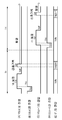
도 6은 행방향으로 서로 인접하는 2개의 유닛에 주목한 때의 각 화소(서브픽셀)행에 인가된 선택 펄스의 경시 변화의 한 예를 도시하는 파형도.
도 7은 하나의 화소(서브픽셀)에 주목한 때의 WSL, DSL, DTL에 인가되는 전압, 게이트 전압, 및 소스 전압의 경시 변화의 한 예를 도시하는 파형도.
도 8은 행방향으로 서로 인접하는 2개의 유닛에 주목한 때의 WSL, DSL, DTL에 인가되는 전압의 경시 변화의 한 예를 도시하는 파형도.
도 9는 도 6의 A로 둘러싸여진 2개의 WSL에 대응하는 2개의 화소 사이의 커플링에 관해 설명하기 위한 파형도.
도 10은 도 6의 B로 둘러싸여진 2개의 WSL에 대응하는 2개의 화소 사이의 커플링에 관해 설명하기 위한 파형도.
도 11은 비교례에 관한 표시 패널에서의 각 화소의 회로 구성의 한 예를 도시하는 도면.
도 12는 도 11의 레이아웃을 구비한 표시 장치에서, 행방향으로 서로 인접하는 2개의 화소에 주목한 때의 WSL, DSL, DTL에 인가되는 전압의 경시 변화의 한 예를 도시하는 파형도.
도 13은 도 11의 레이아웃을 구비한 표시 장치에서, 행방향으로 서로 인접하는 2개의 화소에 주목한 때의 WSL, DSL, DTL에 인가되는 전압의 경시 변화의 다른 예를 도시하는 파형도.
도 14는 묶음 구동에 의해 생기는 휘도 얼룩의 한 예를 도시하는 도면.
도 15는 도 3, 도 4의 레이아웃을 구비한 표시 장치에서, 행방향으로 서로 인접하는 2개의 유닛에 주목한 때의 WSL, DSL, DTL에 인가되는 전압의 경시 변화의 비교례를 도시하는 파형도.
도 16은 도 15의 파형을 WSL의 분지마다 도시하는 파형도.
도 17은 도 16의 D로 둘러싸여진 2개의 WSL에 대응하는 2개의 화소 사이의 커플링에 관해 설명하기 위한 파형도.
도 18은 상기 실시의 형태의 발광 장치의 적용례 1의 외관을 도시하는 사시도.
도 19의 A는 적용례 2의 앞측에서 본 외관을 도시하는 사시도, B는 뒤측에서 본 외관을 도시하는 사시도.
도 20은 적용례 3의 외관을 도시하는 사시도.
도 21은 적용례 4의 외관을 도시하는 사시도.
도 22의 A는 적용례 5의 연 상태의 정면도, B는 그 측면도, C는 닫은 상태의 정면도, D는 좌측면도, E는 우측면도, F는 상면도, G는 하면도.BRIEF DESCRIPTION OF THE DRAWINGS Fig. 1 is a schematic configuration diagram of a display device according to an embodiment of the present technology. Fig.
2 is a diagram showing an example of a circuit configuration of each pixel (subpixel);
3 is a diagram showing an example of a circuit configuration of two display pixels adjacent to each other in the row direction;
4 is a diagram showing another example of the circuit configuration of two display pixels adjacent to each other in the row direction;
5 is a diagram showing an example of a voltage applied to the DTLs of Figs. 3 and 4. Fig.
6 is a waveform diagram showing an example of a change over time of a selection pulse applied to each pixel (subpixel) row when attention is paid to two units adjacent to each other in the row direction.
FIG. 7 is a waveform diagram showing an example of a change over time of a voltage applied to WSL, DSL, and DTL, a gate voltage, and a source voltage when attention is paid to one pixel (subpixel); FIG.
8 is a waveform diagram showing an example of a change with time in voltage applied to WSL, DSL, and DTL when attention is paid to two units adjacent to each other in the row direction;
Fig. 9 is a waveform diagram for explaining coupling between two pixels corresponding to two WSLs surrounded by A in Fig. 6; Fig.
Fig. 10 is a waveform diagram for explaining coupling between two pixels corresponding to two WSLs surrounded by B in Fig. 6; Fig.
11 is a diagram showing an example of a circuit configuration of each pixel in a display panel according to a comparative example.
FIG. 12 is a waveform diagram showing an example of a change over time of a voltage applied to WSL, DSL, and DTL when attention is paid to two pixels adjacent to each other in the row direction in the display device having the layout of FIG. 11;
FIG. 13 is a waveform diagram showing another example of a change over time of voltage applied to WSL, DSL, and DTL when attention is paid to two pixels adjacent to each other in the row direction in the display device having the layout of FIG. 11;
14 is a diagram showing an example of luminance unevenness caused by bundling drive.
15 is a waveform diagram showing a comparative example of changes in voltage applied to WSL, DSL, and DTL when attention is paid to two units adjacent to each other in the row direction in the display device having the layouts of Figs. 3 and 4. Fig. Degree.
Fig. 16 is a waveform diagram showing the waveform of Fig. 15 for each branch of the WSL; Fig.
Fig. 17 is a waveform diagram for explaining coupling between two pixels corresponding to two WSLs surrounded by D in Fig. 16; Fig.
18 is a perspective view showing the external appearance of Application Example 1 of the light emitting device of the above embodiment.
Fig. 19A is a perspective view showing the appearance of the application example 2 as seen from the front side, and B is a perspective view showing the appearance as seen from the rear side.
20 is a perspective view showing the external appearance of Application Example 3;
21 is a perspective view showing the external appearance of Application Example 4;
22A is a front view of the open state of application example 5, B is a side view thereof, C is a front view in a closed state, D is a left side view, E is a right side view, F is a top view, and G is a bottom view.
이하, 발명을 실시하기 위한 형태에 관해, 도면을 참조하여 상세히 설명한다. 또한, 설명은 이하의 순서로 행한다.Hereinafter, embodiments for carrying out the invention will be described in detail with reference to the drawings. The description will be made in the following order.
1. 실시의 형태(표시 장치)1. Embodiment (display device)
2. 변형례(표시 장치)2. Modification (Display)
3. 적용례(전자 기기)3. Application (electronic equipment)
1. 실시의 형태1. Embodiment
구성Configuration
도 1은, 본 기술의 한 실시의 형태에 관한 표시 장치(1)의 개략 구성을 도시한 것이다. 이 표시 장치(1)는, 표시 패널(10)과, 외부로부터 입력된 영상 신호(20A) 및 동기 신호(20B)에 의거하여 표시 패널(10)을 구동하는 구동 회로(20)를 구비하고 있다. 구동 회로(20)는, 예를 들면, 타이밍 생성 회로(21), 영상 신호 처리 회로(22), 신호선 구동 회로(23), 주사선 구동 회로(24), 및 전원선 구동 회로(25)를 갖고 있다.Fig. 1 shows a schematic configuration of a
표시 패널(10)The display panel (10)
표시 패널(10)은, 복수의 화소(11)가 표시 패널(10)의 표시 영역(10A) 전면에 걸쳐서 매트릭스형상으로 배치된 것이다. 표시 패널(10)은, 구동 회로(20)에 의해 각 화소(11)가 액티브 매트릭스 구동됨에 의해, 외부로부터 입력된 영상 신호(20A)에 의거한 화상을 표시하는 것이다.The display panel 10 has a plurality of
도 2는, 화소(11)의 회로 구성의 한 예를 도시한 것이다. 각 화소(11)는, 예를 들면, 화소 회로(12)와, 유기 EL 소자(13)를 갖고 있다. 유기 EL 소자(13)는, 예를 들면, 애노드 전극, 유기층 및 캐소드 전극이 차례로 적층된 구성을 갖고 있다. 유기 EL 소자(13)는, 소자 커패시터(Coled)(도시 생략)를 갖고 있다. 화소 회로(12)는, 예를 들면, 구동 트랜지스터(Tr1), 기록 트랜지스터(Tr2), 유지 커패시터(Cs) 및 보조 커패시터(Csub)에 의해 구성된 것이고, 2Tr2C의 회로 구성으로 되어 있다.Fig. 2 shows an example of the circuit configuration of the
기록 트랜지스터(Tr2)는, 구동 트랜지스터(Tr1)의 게이트에 대한, 영상 신호에 대응하는 신호 전압의 인가를 제어하는 것이다. 구체적으로는, 기록 트랜지스터(Tr2)는, 후술하는 신호선(DTL)의 전압을 샘플링함과 함께 구동 트랜지스터(Tr1)의 게이트에 기록하는 것이다. 구동 트랜지스터(Tr1)는, 유기 EL 소자(13)를 구동하는 것이고, 유기 EL 소자(13)에 직렬로 접속되어 있다. 구동 트랜지스터(Tr1)는, 기록 트랜지스터(Tr2)에 의해 기록된 전압의 크기에 응하여 유기 EL 소자(13)에 흐르는 전류를 제어하는 것이다. 유지 커패시터(Cs)는, 구동 트랜지스터(Tr1)의 게이트-소스 사이에 소정의 전압을 유지하는 것이다. 보조 커패시터(Csub)는, 구동 트랜지스터(Tr1)로부터 공급된 전류의 일부를 유입하는 것이다. 또한, 화소 회로(12)는, 상술한 2Tr2C의 회로에 대해 각종 커패시터나 트랜지스터를 부가한 회로 구성으로 되어 있어도 좋고, 상술한 2Tr2C의 회로 구성과는 다른 회로 구성으로 되어 있어도 좋다.The writing transistor Tr2 controls the application of the signal voltage corresponding to the video signal to the gate of the driving transistor Tr1. Specifically, the writing transistor Tr2 samples the voltage of the signal line DTL to be described later and records it in the gate of the driving transistor Tr1. The driving transistor Tr1 drives the
구동 트랜지스터(Tr1) 및 기록 트랜지스터(Tr2)는, 예를 들면, n채널 MOS형의 박막 트랜지스터(TFT(Thin Film Transistor))에 의해 형성되어 있다. 또한, TFT의 종류는 특히 한정되는 것이 아니고, 예를 들면, 역스태거 구조(이른바 보텀 게이트형)라도 좋고, 스태거 구조(톱 게이트형)라도 좋다. 또한, 구동 트랜지스터(Tr1) 및 기록 트랜지스터(Tr2)는, p채널 MOS형의 TFT에 의해 형성되어 있어도 좋다.The driving transistor Tr1 and the writing transistor Tr2 are formed by, for example, an n-channel MOS type thin film transistor (TFT (Thin Film Transistor)). The type of the TFT is not particularly limited. For example, a reverse stagger structure (so-called bottom gate type) or a stagger structure (top gate type) may be used. The driving transistor Tr1 and the writing transistor Tr2 may be formed by a p-channel MOS type TFT.
표시 패널(10)은, 행방향으로 연재되는 복수의 주사선(WSL)과, 열방향으로 연재되는 복수의 신호선(DTL)과, 행방향으로 연재되는 복수의 전원선(DSL)과, 행방향으로 연재되는 복수의 캐소드선(CTL)(기준 전압선)을 갖고 있다. 주사선(WSL)은, 각 화소(11)의 선택에 이용된 것이다. 신호선(DTL)은, 영상 신호에 응한 신호 전압의, 각 화소(11)에의 공급에 이용되는 것이다. 전원선(DSL)은, 각 화소(11)에의 구동 전류의 공급에 이용되는 것이다.The display panel 10 includes a plurality of scanning lines WSL extending in the row direction, a plurality of signal lines DTL extending in the column direction, a plurality of power supply lines DSL extending in the row direction, And has a plurality of cathode lines CTL (reference voltage lines) extending in series. The scanning line WSL is used for selection of each
각 신호선(DTL)과 각 주사선(WSL)과의 교차점 부근에는, 화소(11)가 마련되어 있다. 각 신호선(DTL)은, 후술하는 신호선 구동 회로(23)의 출력단(도시 생략)과, 기록 트랜지스터(Tr2)의 소스 또는 드레인에 접속되어 있다. 각 주사선(WSL)은, 후술하는 주사선 구동 회로(24)의 출력단(도시 생략)과, 기록 트랜지스터(Tr2)의 게이트에 접속되어 있다. 각 전원선(DSL)은, 고정의 전압을 출력하는 전원의 출력단(도시 생략)과, 구동 트랜지스터(Tr1)의 소스 또는 드레인에 접속되어 있다. 캐소드선(CTL)은, 예를 들면, 표시 영역(10A)의 주위에 마련된 부재로서, 또한 기준의 전압으로 되어 있는 부재에 접속되어 있다.A
기록 트랜지스터(Tr2)의 게이트는, 주사선(WSL)에 접속되어 있다. 기록 트랜지스터(Tr2)의 소스 또는 드레인이 신호선(DTL)에 접속되고, 기록 트랜지스터(Tr2)의 소스 및 드레인중 신호선(DTL)에 미접속의 단자가 구동 트랜지스터(Tr1)의 게이트에 접속되어 있다. 구동 트랜지스터(Tr1)의 소스 또는 드레인이 전원선(DSL)에 접속되고, 구동 트랜지스터(Tr1)의 소스 및 드레인중 전원선(DSL)에 미접속의 단자가 유기 EL 소자(13)의 애노드에 접속되어 있다. 유지 커패시터(Cs)의 일단이 구동 트랜지스터(Tr1)의 게이트에 접속되고, 유지 커패시터(Cs)의 타단이 구동 트랜지스터(Tr1)의 소스(도 2에서는 유기 EL 소자(13)측의 단자)에 접속되어 있다. 즉, 유지 커패시터(Cs)는, 구동 트랜지스터(Tr1)의 게이트-소스 사이에 삽입되어 있다. 보조 커패시터(Csub)의 일단이 구동 트랜지스터(Tr1)의 소스(도 2에서는 유기 EL 소자(13)측의 단자)에 접속되고, 보조 커패시터(Csub)의 타단이 캐소드선(CTL)에 접속되어 있다.The gate of the writing transistor Tr2 is connected to the scanning line WSL. The source or the drain of the writing transistor Tr2 is connected to the signal line DTL and the terminal not connected to the signal line DTL of the source and the drain of the writing transistor Tr2 is connected to the gate of the driving transistor Tr1. The source or the drain of the driving transistor Tr1 is connected to the power source line DSL and the terminal of the source and the drain of the driving transistor Tr1 which is not connected to the power source line DSL is connected to the anode of the
표시 패널(10)은, 또한, 도 2에 도시한 바와 같이, 유기 EL 소자(13)의 캐소드에 접속된 그라운드선(GND)을 갖고 있다. 그라운드선(GND)은, 그라운드 전위로 되어 있는 외부 회로(도시 생략)와 전기적으로 접속되는 것이다. 그라운드선(GND)은, 예를 들면, 표시 영역(10A) 전체에 걸쳐서 형성된 시트형상의 전극이다. 또한, 그라운드선(GND)은, 화소행 또는 화소렬에 대응하여 작은꼬리표형상((短冊狀)으로 형성된 띠형상의 전극이라도 좋다. 표시 패널(10)은, 또한, 예를 들면, 표시 영역(10A)의 주연(周緣)에, 영상을 표시하지 않는 프레임 영역을 갖고 있다. 프레임 영역은, 예를 들면, 차광 부재에 의해 덮여 있다.The display panel 10 also has a ground line (GND) connected to the cathode of the
도 3, 도 4는, 열방향으로 서로 인접하는 2개의 표시 화소(14)(후술)에서의 회로 구성의 한 예를 도시한 것이다. 도 3은, n번째(1≤n<N, N은 표시 화소행의 총수(짝수)) 및 n+1번째의 표시 화소행에서의 각 표시 화소(14)의 회로 구성의 한 예를 도시한 것이다. 도 4는, n+2번째 및 n+3번째의 표시 화소행에서의 각 표시 화소(14)의 회로 구성의 한 예를 도시한 것이다. 여기서, 표시 화소행이란, 행방향으로 나열하여 배치된 복수의 표시 화소(14)에 의해 형성된 라인을 가리키고 있다. 한편, 화소행이란, 행방향으로 나열하여 배치된 복수의 화소(11)에 의해 형성된 라인을 가리키고 있고, 서브픽셀행(行)에 상당하는 것이다. 이하에서는, 화소행과 표시 화소행과의 혼동을 피하기 위해, 화소행을 서브픽셀행이라고 칭한다.Figs. 3 and 4 show an example of a circuit configuration in two display pixels 14 (described later) that are adjacent to each other in the column direction. 3 shows an example of the circuit configuration of each
각 화소(11)의 회로 레이아웃은, n번째 표시 화소행과, n+2번째 표시 화소행에서, 서로 공통으로 되어 있고, 또한, n+1번째 표시 화소행과, n+3번째 표시 화소행에서, 서로 공통으로 되어 있다. 이하에서는, 설명의 중복을 피하는 취지로, n+2번째 표시 화소행 및 n+3번째 표시 화소행에서의 각 화소(11)의 회로 레이아웃에 관한 설명을 생략한다.The circuit layout of each
각 화소(11)는, 표시 패널(10)상의 화면을 구성하는 최소 단위의 점에 대응하는 것이다. 표시 패널(10)은, 컬러 표시 패널로 되어 있고, 화소(11)는, 예를 들면 적, 녹, 청, 또는 백 등의 단색의 광을 발하는 서브픽셀에 상당한다. 또한, 화소(11)는, 예를 들면 적, 녹, 청, 또는 백 등의 단색의 광을 발하는 서브픽셀에 상당하고 있어도 좋다.Each
본 실시의 형태에서는, 발광색이 서로 다른 4개의 화소(11)에 의해 표시화소(14)가 구성되어 있다. 즉, 발광색의 종류의 수는 4이고, 각 표시화소(14)에 포함되는 화소(11)의 수도 4이다. 표시화소(14)에 포함되는 4개의 화소(11)는, 예를 들면, 적색광을 발하는 화소(11R), 녹색광을 발하는 화소(11G), 청색광을 발하는 화소(11B), 및 백색광을 발하는 화소(11W)로 구성되어 있다. 각 표시화소(14)에서, 4개의 화소(11)는, 이른바 밭전자(田字) 배열(4 square)로 되어 있고, 2×2의 매트릭스로 배치되어 있다. 또한, 각 표시화소(14)에서, 4개의 화소(11)는 공통의 색 배열로 되어 있다. 예를 들면, 도 3에 도시한 바와 같이, 밭전자 배열의 좌상에 화소(11R)가 배치되고, 밭전자 배열의 좌하에 화소(11G)가 배치되고, 밭전자 배열의 우하에 화소(11B)가 배치되고, 밭전자 배열의 우상에 화소(11W)가 배치되어 있다.In the present embodiment, the
표시 화소행은 k개(k≥2)의 표시 화소행을 각각 포함하는 구동 유닛으로 분류된다. 각각의 구동 유닛은 L개의 유닛 기록 주사선(WSL)을 포함한다. 1개의 구동 유닛에 포함되는 표시 화소행의 수는 2 이상, 발광색의 종류의 수 이하이다. 구체적으로는, 2개의 유닛 기록 주사선(WSL)과 2개의 표시 화소행은, 각각의 구동 유닛에 포함된다(예를 들면, L=2, k=2). 유닛 기록 주사선(WSL)의 총수는, 표시 화소행의 총수와 동등하게 되어 있고, N개로 되어 있다. 또한, 도 3중의 n은, 1 이상, N 이하의 정의 정수이다. 도 3중의 WSL(n)은, n번째(n행째)의 유닛 기록 주사선(WSL)을 의미하고 있다.And the display pixel row is classified into a drive unit each including k (k? 2) display pixel rows. Each drive unit includes L unit write scan lines WSL. The number of display pixel lines included in one drive unit is not less than 2 and not more than the number of kinds of light emission colors. Specifically, two unit write scan lines WSL and two display pixel rows are included in each drive unit (for example, L = 2, k = 2). The total number of unit recording scanning lines WSL is equal to the total number of display pixel rows, and is N number. In Fig. 3, n is a positive integer of 1 or more and N or less. WSL (n) in Fig. 3 means the n-th (n-th) unit write scan line WSL.
각 유닛 기록 주사선(WSL)은, 특정한 발광색을 갖는 각각의 구동 유닛 내에서 화소(11) 전부에 접속되어 있다. 구체적으로는, 하나의 구동 유닛에 포함되는 2개의 유닛 기록 주사선(WSL(n), WSL(n+1))에서, 유닛 기록 주사선(WSL(n))은, 하나의 구동 유닛에 포함되는 적색 화소(11R) 및 백색 화소(11W) 모두에 접속되어 있고, 유닛 기록 주사선(WSL(n+1))은, 하나의 구동 유닛에 포함되는 녹색 화소(11G) 및 청색 화소(11B) 모두에 접속되어 있다. 하나의 구동 유닛 내에서 행이 서로 다르고, 또한 열방향에서 서로 인접하는 2개의 표시화소(14)에서, 각 주사선(WSL)에 의하여 공유되는 2종류의 발광색을 갖는 화소(11)의 발광색의 조합이 동등하게 되어 있다.Each unit write scan line WSL is connected to all of the
각 유닛 기록 주사선(WSL)(WSL(n) 내지 WSL(n+3))은, 공통선으로써 구성된 복수의 기록 주사선(분지(分枝))에 의하여, 각각의 유닛 기록 주사선(WSL)은 하나의 구동 유닛에 포함되는 표시 화소행의 수와 동일한 개수의 구성을 이루는 단일의 기록 주사선(분지)을 포함하도록 구성된다(예를 들면, k개 분지)(즉, 2개의 분지(제1 배선, 제2 배선))을 갖고 있다. 각 단일의 기록 주사선(분지)는 하나의 서브픽셀행에 할당되어 있다. 신호 구동 유닛에서, 특정된 유닛 기록 주사선(WSL)의 분지는 구동 유닛에 포함된 표시 화소행의 유사하게 위치한 서브픽셀행에 각각 접속되어 있어서, 동일 색의 구동 유닛에서 각각의 픽셀은 동일한 유닛 기록 주사선(WSL)에 접속된다. 예를 들면, 이러한 특정한 실시의 형태에서, 유닛 기록 주사선(WSL(n+1))의 분지가 구동 유닛을 포함하는 2개의 표시 화소행의 하단의 서브픽셀행에 접속되어 있을 때, 유닛 기록 주사선(WSL(n))의 분지는 구동 유닛에 포함된 2개의 표시 화소행의 상단 서브픽셀행에 접속된다. 이러한 특정한 실시의 형태에서, 특정한 유닛 기록 주사선의 각각의 분지는 당해 표시 패널(10) 내에서의 분지와 서로 접속되어 있다. 분지끼리의 접속점(C1)은, 표시 영역(10A) 내에 있어도 좋고, 표시 영역(10A)의 주연(프레임 영역) 내에 있어도 좋다. 또한, 표시 패널(10)의 법선 방향에서 본 때에, 동일 유닛 내에서, 각 유닛 기록 주사선(WSL)은, 다른 유닛 기록 주사선(WSL)과 교차하고 있다. 각 유닛 기록 주사선(WSL)의 분지는, 밭전자 배열의 중앙을 횡단하고 있다. 기록 트랜지스터(Tr2)의 게이트 전극(14A)은, 유닛 기록 주사선(WSL)의 분지에 접속되어 있다.Each unit write scan line WSL (WSL (n) to WSL (n + 3)) is formed by a plurality of write scan lines (branch) (For example, k branches) (that is, two branches (the first wiring, the second wiring, and the third wiring) constituting the same number of display pixel lines as the number of display pixel lines included in the driving unit of the driving unit Second wiring). Each single recording scan line (branch) is assigned to one subpixel row. In the signal driving unit, the branches of the specified unit recording scan line WSL are connected to the similarly located sub pixel rows of the display pixel rows included in the driving unit, respectively, so that in the driving units of the same color, And is connected to the scanning line WSL. For example, in this specific embodiment, when the branch of the unit write scan line WSL (n + 1) is connected to the lower sub-pixel row of the two display pixel rows including the drive unit, (WSL (n)) is connected to the upper sub-pixel row of the two display pixel rows included in the driving unit. In this particular embodiment, each branch of a particular unit write scan line is connected to a branch within the display panel 10 in question. The connection point C1 between the branches may be within the
복수의 유닛 전원선(DSL)은, 하나의 구동 유닛마다 1개씩 할당되어 있다. 따라서, 하나의 구동 유닛에 포함되는 유닛 전원선(DSL)의 수는 1이다. 유닛 전원선(DSL)의 총수는 J(=N/k)이다. 이러한 특정한 실시의 형태에서, k=2 이고, 따라서 J=N/2로 표시 화소행의 총수의 반분에 상당하고 있다. 또한, 도 3중의 j는, 1 이상, N/2 이하의 정의 정수이고, 도 3중의 DSL(j)은, j번째의 전원선(DSL)을 의미하고 있다. 각 유닛 전원선(DSL)은, 하나의 구동 유닛 내의 모든 화소(11)에 접속되어 있다. 구체적으로는, 하나의 구동 유닛에 포함되는 하나의 유닛 전원선(DSL)은, 하나의 유닛에 포함되는 모든 화소(11)(11R, 11G, 11B, 11W)에 접속되어 있다.One unit power supply line (DSL) is allocated for each one drive unit. Therefore, the number of unit power supply lines (DSL) included in one driving unit is one. The total number of unit power supply lines (DSL) is J (= N / k). In this particular embodiment, k = 2 and thus J = N / 2 corresponds to half the total number of display pixel rows. 3 is a positive integer equal to or greater than 1 and equal to or smaller than N / 2, and DSL (j) in FIG. 3 means the j-th power supply line DSL. Each unit power supply line (DSL) is connected to all the
또한, 각 유닛 전원선(DSL)은 공통선으로써 구성된 복수의 전원선(분지)에 의하여 구성되고, 각 유닛 전원선(DSL)은 k개의 구성을 이루는 단일의 전원선(분지)을 포함하고, 예를 들면, 하나의 유닛에 포함되는 표시 화소행과 동일한 개수를 갖는다(즉, 이러한 특정한 실시의 형태에서, 2개의 분지). 이러한 특정한 실시의 형태에서, 유닛 전원선(DSL(DSL(j), DSL(j+1))의 각 분지는, 당해 표시 패널(10) 내에서 서로 접속되어 있다. 분지 사이의 접속점(C2)은, 표시 영역(10A) 내에 있어도 좋고, 표시 영역(10A)의 주연(프레임 영역) 내에 있어도 좋다. 이와 같이, 유닛 기록 주사선(WSL) 및 유닛 전원선(DSL)에 분지를 마련함에 의해, 유닛 주사선(WSL)의 간격이나, 유닛 전원선(DSL)의 간격을 넓게 할 수 있다. 그 결과, 배선 레이아웃이 용이해진다. 각 전원선(DSL)의 분지는, 밭전자 배열의 중앙을 횡단하고 있다.Each unit power supply line (DSL) is constituted by a plurality of power supply lines (branches) constituted by a common line, and each unit power supply line (DSL) includes a single power supply line (branch) For example, it has the same number of display pixel lines included in one unit (i. E., Two branches in this particular embodiment). In this specific embodiment, each branch of the unit power supply lines DSL (DSL (j), DSL (j + 1)) is connected to each other in the display panel 10. The connection point C2 between branches (Frame region) of the
유닛 전원선(DSL) 및 유닛 기록 주사선(WSL)의 분지 구성은 실례로서 설명되었으므로, 본 개시는 특정 구성으로 제한되지 않는다. 특히, 본 개시와 첨부된 청구항에서, 멀티플와이어링(multiple wiring)은 "공통선으로 구성된"으로 하였으며, 이러한 와이어링은 동시에 인가된 동일한 전압을 갖는다. 이것은, 예를 들면, 와이어링은 직접적으로 서로 접속되기 때문이다. 그러나, "공통선으로 구성된"인 멀티플와이어링은 동시에 동일한 전압이 인가되기만 하면 서로 직접적으로 연결될 필요가 없다(예를 들면, 물리적으로 분리되더라도 동일 선과 같이 실질적으로 취급된다). 예를 들면, 구동 회로는 동시에 복수의 와이어링에 동일한 전압을 인가하도록 구성되며, 이 경우 복수의 와이어링은 "공통선으로 구성된" 것이다.Since the branch structure of the unit power supply line DSL and the unit recording scan line WSL has been described as an example, the present disclosure is not limited to a specific structure. In particular, in the present disclosure and in the appended claims, multiple wirings are referred to as "consisting of common lines ", and such wiring has the same voltage applied at the same time. This is because, for example, wiring is directly connected to each other. However, multiple wirings, which are "composed of common lines, " need not be connected directly to one another (e.g., physically separated, but treated substantially like the same line) as long as the same voltage is applied. For example, the driving circuit is configured to simultaneously apply the same voltage to a plurality of wirings, in which case the plurality of wirings are "composed of a common line ".
신호선(DTL)은 열방향으로 연재하게 제공된다. 서브픽셀(11)열마다 신호선(DTL)의 개수는 구동 유닛마다 표시 화소행의 개수(k)와 동일하다. 본 실시의 형태에서, k=2이고, 따라서 각 서브픽셀(11)의 열에 2개의 신호선(DTL)이 있다. 하나의 구동 유닛 내에, 각 신호선(DTL)은 신호선(DTL)에 대응하는 신호 열에 있는 하나의 표시 화소의 화소(11) 전부와 접속된다. 따라서, 도 3에서 도시한 본 실시의 형태에서, 신호선(DTL(m))은 화소(11)의 제1의 열에 있는 제1의 표시 화소의 화소(11) 양쪽 모두에 접속되고, 신호선(DTL(m+1))은 화소(11)의 제1의 열에 있는 제2의 표시 화소의 화소(11) 양쪽 모두에 접속되고, 신호선(DTL(m+2))은 화소(11)의 제2의 열에 있는 제1의 표시 화소의 화소(11) 양쪽 모두에 접속되고, 신호선(DTL(m+3))은 화소(11)의 제2의 열에 있는 제2의 표시 화소의 화소(11) 양쪽 모두에 접속된다. 도 3의 예에서, 복수의 신호선(DTL)은, 각 표시 화소행에서 표시 화소(14)마다 2개씩 할당되어 있다. 각 표시 화소행에서 표시 화소(14)마다 할당된 2개의 신호선(DTL)에서, 하나의 신호선(DTL)은, 동일 유닛 주사선(WSL)이 공유되지 않은 2종류의 발광색을 갖는 화소(11)에 접속되어 있고, 다른쪽의 신호선(DTL)은, 나머지 2종류의 발광색을 갖는 화소(11)에 접속되어 있다. 이하에서는, n행째 및 n+1행째의 표시 화소행에 포함되는 복수의 표시 화소(14)중, 열방향으로 서로 인접하는 2개의 표시 화소(14)에 주목하여, 상기한 접속 상태에 관해 설명한다. 또한, 상기한 2개의 표시 화소(14)는, 하나의 구동 유닛 내에서 표시 화소행이 서로 다르고, 또한 열방향으로 서로 인접하는 2개의 표시 화소(14)에 상당한다.The signal line DTL is provided serially in the column direction. The number of signal lines DTL for each column of
2개의 표시 화소(14)중 n번째의 표시 화소행에 포함되는 표시 화소(14)에는, 2개의 신호선(DTL(m), DTL(m+2))이 할당되어 있다. 또한, 2개의 표시 화소(14)중 n+1번째의 표시 화소행에 포함되는 표시 화소(14)에는, 2개의 신호선(DTL(m+2), DTL(m+3))이 할당되어 있다. 즉, 하나의 구동 유닛 내에서 표시 화소행이 서로 다르고, 또한 열방향으로 서로 인접하는 2개의 표시 화소(14)에서, 한쪽의 표시 화소(14)에 대해서는 짝수열째의 2개의 신호선(DTL(m), DTL(m+2))이 할당되고, 다른쪽의 표시 화소(14)에 대해서는 홀수열째의 2개의 신호선(DTL(m+1), DTL(m+3))이 할당되어 있다. 이에 의해, 신호선(DTL)의 총수가 최소한으로 억제되어 있다.Two signal lines DTL (m) and DTL (m + 2) are assigned to the
복수의 신호선(DTL)은, 열방향에서 서로 인접하는 2개의 표시 화소(14)마다 4개씩 할당되어 있다. 따라서, 신호선(DTL)의 총 개수는, M개로 되어 있다(M=k·C이고 C는 서브픽셀 회로의 열의 총 개수이다). 도 3에서, m은, 1 이상, M-4 이하의 정의 정수이고, 1 이외의 경우에는 [4의 배수+1]에 상당하는 수이다. 따라서, 도 3중의 DTL(m)은, m번째의 신호선(DTL)을 의미하고 있다. 열방향에서 서로 인접하는 2개의 표시 화소(14)에는, 예를 들면, 4개의 신호선(DTL(m), DTL(m+1), DTL(m+2), DTL(m+3))이 할당되어 있다. 4개의 신호선(DTL(m), DTL(m+1), DTL(m+2), DTL(m+3))은, 행방향에서, 이 순서로 나열하여 배치되어 있다. 각 표시 화소(14)에서, 4개의 화소(11)중 좌측의 2개의 화소(11)가, 행방향에서 신호선(DTL(m))과 신호선(DTL)(m+1)에 의해 끼어져 있다. 또한, 각 표시 화소(14)에서, 4개의 화소(11)중 우측의 2개의 화소(11)가, 행방향에서 신호선(DTL(m+2))과 신호선(DTL(m+3))에 의해 끼어져 있다.The plurality of signal lines DTL are allocated for each of the two
또한, 하나의 구동 유닛 내에서 표시 화소행이 서로 다르고, 또한 열방향에서 서로 인접하는 2개의 표시 화소(14)에서, 발광색이 서로 동등한 2개의 화소(11)가 공통의 2개의 신호선(DTL)의 사이에 배치되어 있다. 구체적으로는, 하나의 구동 유닛 내에서 표시 화소행이 서로 다르고, 또한 열방향에서 서로 인접하는 2개의 표시 화소(14)에서, 2개의 화소(11R)가 2개의 신호선(DTL(m), DTL(m+1))의 사이에 배치되어 있다. 마찬가지로, 하나의 구동 유닛 내에서 표시 화소행이 서로 다르고, 또한 서로 인접하는 2개의 표시 화소(14)에서, 2개의 화소(11G)가 2개의 신호선(DTL(m), DTL(m+1))의 사이에 배치되어 있다. 또한, 하나의 구동 유닛 내에서 표시 화소행이 서로 다르고, 또한 서로 인접하는 2개의 표시 화소(14)에서, 2개의 화소(11B)가 2개의 신호선(DTL(m+2), DTL(m+3))의 사이에 배치되어 있다. 또한, 하나의 구동 유닛 내에서 표시 화소행이 서로 다르고, 또한 서로 인접하는 2개의 표시 화소(14)에서, 2개의 화소(11W)가 2개의 신호선(DTL(m+2), DTL(m+3))의 사이에 배치되어 있다.Two
상기한 2개의 신호선(DTL(m), DTL(m+2))은, 각각, 주사선(WSL)이 서로 공유되지 않는 2종류의 발광색을 갖는 화소(11)에 접속되어 있다. 구체적으로는, 신호선(DTL(m))은, 주사선(WSL)이 서로 공유되지 않은 2종류의 발광색을 갖는 화소(11R, 11G)에 접속되어 있고, 신호선(DTL(m+2))은, 주사선(WSL)이 서로 공유되지 않은 2종류의 발광색을 갖는 화소(11B, 11W)에 접속되어 있다. 또한, 상기 2개의 표시 화소(14)중 n+1번째의 표시 화소행에 포함되는 표시 화소(14)에는, 2개의 신호선(DTL(m+1), DTL(m+3))이 할당되어 있다. 그 2개의 신호선(DTL(m+1), DTL(m+3))은, 주사선(WSL)이 서로 공유되지 않은 2종류의 발광색을 갖는 화소(11)에 접속되어 있다. 구체적으로는, 신호선(DTL)(m+1)은, 주사선(WSL)이 공유되지 않은 2종류의 발광색을 갖는 화소(11R, 11G)에 접속되어 있고, 신호선(DTL(m+3))은, 나머지 2종류의 발광색을 갖는 화소(11B, 11W)에 접속되어 있다.The two signal lines DTL (m) and DTL (m + 2) described above are connected to the
복수의 캐소드선(CTL)은, 2개의 서브픽셀행마다 1개씩 할당되어 있다. 구체적으로는, 복수의 캐소드선(CTL)은, 열방향에서 서로 인접함과 함께 표시 화소행의 서로 다른 2개의 서브픽셀행마다 1개씩 할당되어 있다. 예를 들면, 도 3에 도시한 바와 같이, n번째 표시 화소행 내의 하단의 서브픽셀의 하나인 화소(11G)와, n+1번째 표시 화소행 내의 상단의 서브픽셀의 하나인 화소(11R)가, 공통의 캐소드선(CTL)에 접속되어 있다. 마찬가지로, 예를 들면, n+1번째 표시 화소행 내의 하단의 서브픽셀의 하나인 화소(11G)와, n+2번째 표시 화소행 내의 상단의 서브픽셀의 하나인 화소(11R)가, 공통의 캐소드선(CTL)에 접속되어 있다. 또한, 예를 들면, 도 3에 도시한 바와 같이, n번째 표시 화소행 내의 하단의 서브픽셀의 하나인 화소(11B)와, n+1번째 표시 화소행 내의 상단의 서브픽셀의 하나인 화소(11W)가, 공통의 캐소드선(CTL)에 접속되어 있다. 마찬가지로, 예를 들면, n+1번째 표시 화소행 내의 하단의 서브픽셀의 하나인 화소(11B)와, n+2번째 표시 화소행 내의 상단의 서브픽셀의 하나인 화소(11W)가, 공통의 캐소드선(CTL)에 접속되어 있다.One of the plurality of cathode lines CTL is allocated to each of two subpixel rows. Specifically, the plurality of cathode lines CTL are adjacent to each other in the column direction, and one pixel line CTL is allocated to each of two different sub-pixel rows of the display pixel row. For example, as shown in Fig. 3, a
각 캐소드선(CTL)은, 할당된 2개의 서브픽셀행에 포함되는 모든 보조 커패시터(Csub)에 접속되어 있다. 예를 들면, 도 3에 도시한 바와 같이, n번째 표시 화소행 내의 하단의 서브픽셀행에 포함되는 모든 화소(11G, 11B)의 보조 커패시터(Csub)와, n+1번째 표시 화소행 내의 상단의 서브픽셀행에 포함되는 모든 화소(11R, 11W)의 보조 커패시터(Csub)가, 공통의 캐소드선(CTL)에 접속되어 있다. 마찬가지로, 예를 들면, 도 3, 도 4에 도시한 바와 같이, n+1번째 표시 화소행 내의 하단의 서브픽셀행에 포함되는 모든 화소(11G, 11B)의 보조 커패시터(Csub)와, n+2번째 표시 화소행 내의 상단의 서브픽셀행에 포함되는 모든 화소(11R, 11W)의 보조 커패시터(Csub)가, 공통의 캐소드선(CTL)에 접속되어 있다.Each cathode line CTL is connected to all the auxiliary capacitors Csub included in the two allocated subpixel rows. For example, as shown in Fig. 3, an auxiliary capacitor Csub of all the
구동 회로(20)In the driving
다음에, 구동 회로(20)에 관해 설명한다. 구동 회로(20)는, 상술한 바와 같이, 예를 들면, 타이밍 생성 회로(21), 영상 신호 처리 회로(22), 신호선 구동 회로(23), 주사선 구동 회로(24) 및 전원선 구동 회로(25)를 갖고 있다. 타이밍 생성 회로(21)는, 구동 회로(20) 내의 각 회로가 연동하여 동작하도록 제어하는 것이다. 타이밍 생성 회로(21)는, 예를 들면, 외부로부터 입력된 동기 신호(20B)에 응하여(동기하여), 상술한 각 회로에 대해 제어 신호(21A)를 출력하도록 되어 있다.Next, the driving
영상 신호 처리 회로(22)는, 예를 들면, 외부로부터 입력된 디지털의 영상 신호(20A)에 대해 소정의 보정을 행하고, 그에 의해 얻어진 영상 신호(22A)를 신호선 구동 회로(23)에 출력하는 것이다. 소정의 보정으로서는, 예를 들면, 감마 보정이나, 오버드라이브 보정 등을 들 수 있다.The video
신호선 구동 회로(23)는, 예를 들면, 제어 신호(21A)의 입력에 응하여(동기하여), 영상 신호 처리 회로(22)로부터 입력된 영상 신호(22A)에 대응하는 아날로그의 신호 전압을, 각 신호선(DTL)에 인가하는 것이다. 신호선 구동 회로(23)는, 예를 들면, 2종류의 전압(Vofs, Vsig)을 출력 가능하게 되어 있다. 구체적으로는, 신호선 구동 회로(23)는, 주사선 구동 회로(24)에 의해 선택된 화소(11)에, 신호선(DTL)을 통하여 2종류의 전압(Vofs, Vsig)을 공급하도록 되어 있다.The signal
도 5는, 열방향으로 서로 인접하는 2개의 구동 유닛에서 열방향으로 배열된 4개의 표시 화소(14)에 접속된 4개의 신호선(DTL)(DTL(m), DTL(m+1, DTL(m+2), DTL(m+3))에 대해, 유닛 기록 주사선(WSL)의 주사에 응하여 순차적으로, 인가되는 신호 전압(V(n), V(n+1), V(n+2), V(n+3))의 한 예를 도시한 것이다. 신호선 구동 회로(23)는, 유닛 기록 주사선(WSL(n))의 선택에 대응하여 신호 전압(V(n))을 출력하고, 유닛 기록 주사선(WSL(n+1))의 선택에 대응하여 신호 전압(V(n+1))을 출력하도록 되어 있다. 마찬가지로, 신호선 구동 회로(23)는, 유닛 기록 주사선(WSL(n+2))의 선택에 대응하여 신호 전압(V(n+2))을 출력하고, 유닛 기록 주사선(WSL)(n+3)의 선택에 대응하여 신호 전압(V(n+3))을 출력하도록 되어 있다. 여기서, 주사선 구동 회로(24)는, 후술하는 바와 같이, 신호 전압의 기록에 즈음하여, 유닛 기록 주사선(WSL)을, WSL(n+1), WSL(n), WSL(n+3), WSL(n+2)의 순서로 선택하도록 되어 있다. 그 때문에, 신호선 구동 회로(23)는, 신호 전압의 기록에 즈음하여, 신호 전압(Vsig)을, V(n+1), V(n), V(n+3), V(n+2)의 순서로 출력하도록 되어 있다.5 shows the relationship between the four signal lines DTL (DTL (m), DTL (m + 1, DTL (m)) connected to the four
신호선 구동 회로(23)는, 예를 들면, 도 5에 도시한 바와 같이, 주사선 구동 회로(24)에 의해 동시에 선택된 복수의 화소(11)중, n번째 표시 화소행에 속하는 복수의 화소(11)에 대해서는, 짝수번째 열의 신호선(DTL(m), DTL(m+2))을 통하여, n번째 표시 화소행에 대응하는 전압(Vsig)(Vsig(n, m), Vsig(n, m+2))을 공급하도록 되어 있다. 또한, 신호선 구동 회로(23)는, 주사선 구동 회로(24)에 의해 동시에 선택된 복수의 화소(11)중, n+1번째 표시 화소행에 속하는 복수의 화소(11)에 대해서는, 홀수번째 열의 신호선(DTL(m+1), DTL(m+3))을 통하여, n+1번째 표시 화소행에 대응하는 전압(Vsig)(Vsig(n+1, m+1), Vsig(n+1, m+3))을 공급하도록 되어 있다.5, the signal
즉, 신호선 구동 회로(23)는, 신호 기록시에, 주사선(WSL(n))이 선택된 때에는, 짝수번째 열의 신호선(DTL(m), DTL(m+2))에 대해 n번째 표시 화소행에 대응하는 전압(Vsig(n, m), Vsig(n, m+2))을 출력하는 동시에, 홀수번째 열의 신호선(DTL(m+1), DTL(m+3))에 대해 n+1번째 표시 화소행에 대응하는 전압(Vsig(n, m+1), Vsig(n, m+3))을 출력하도록 되어 있다. 또한, 신호선 구동 회로(23)는, 신호 기록시에, 주사선(WSL(n+1))이 선택된 때에는, 짝수번째 열의 신호선(DTL(m), DTL(m+2))에 대해 n+1번째 표시 화소행에 대응하는 전압(Vsig(n+1, m), Vsig(n+1, m+2))을 출력하는 동시에, 홀수번째 열의 신호선(DTL(m+1), DTL(m+3))에 대해 n번째 표시 화소행에 대응하는 전압(Vsig(n, m+1), Vsig(n, m+3))을 출력하도록 되어 있다. 또한, 신호선 구동 회로(23)는, n+2번째 표시 화소행 및 n+3번째 표시 화소행에 대해서도, n번째 표시 화소행 및 n+1번째 표시 화소행과 마찬가지로 하여, 전압을 인가하도록 되어 있다.That is, when the signal
Vsig는, 영상 신호(20A)에 대응하는 전압값으로 되어 있다. Vofs는, 영상 신호(20A)와는 관계가 없는 일정 전압이다. Vsig의 최소 전압은 Vofs보다도 낮은 전압값으로 되어 있고, Vsig의 최대 전압은 Vofs보다도 높은 전압값으로 되어 있다.Vsig is a voltage value corresponding to the
주사선 구동 회로(24)에 의해 동시에 선택된 복수의 화소(11)중, 짝수번째의 신호선(DTL(m))과, 홀수번째의 신호선(DTL(m+1))과의 사이에 배치된 2개의 화소(11)는, 발광색이 서로 동등한 화소이다. 마찬가지로, 주사선 구동 회로(24)에 의해 동시에 선택된 복수의 화소(11)중, 짝수번째의 신호선(DTL(m+2))과, 홀수번째의 신호선(DTL(m+3))과의 사이에 배치된 2개의 화소(11)도, 발광색이 서로 동등한 화소이다. 따라서, 신호선 구동 회로(23)는, 유닛 기록 주사선(WSL(n))이 선택된 때에, 신호선(DTL(m), DTL(m+1))에 대해, 발광색이 서로 동등한 화소에 대응하는 전압(Vsig)을 출력하는 동시에, 신호선(DTL(m+2), DTL(m+3))에 대해, 다른 종류로 발광색이 서로 동등한 화소에 대응하는 전압(Vsig)을 출력하도록 되어 있다. 예를 들면, 신호선 구동 회로(23)는, 유닛 기록 주사선(WSL(n))이 선택된 때에, 신호선(DTL(m), DTL(m+1))에 대해, 화소(11R)에 대응하는 전압(Vsig)을 출력하는 동시에, 신호선(DTL(m+2), DTL(m+3))에 대해, 화소(11W)에 대응하는 전압(Vsig)을 출력하도록 되어 있다.Numbered signal line DTL (m + 1) among the plurality of
주사선 구동 회로(24)는, 예를 들면, 제어 신호(21A)의 입력에 응하여(동기하여), 복수의 주사선(WSL)을 소정의 시퀀스로 선택함에 의해, Vth보정이나, 신호 전압(Vsig)의 기록, 및 μ보정을 소망하는 순번으로 실행시키는 것이다. 여기서, Vth보정이란, 구동 트랜지스터(Tr1)의 게이트-소스 사이 전압(Vgs)을 구동 트랜지스터의 임계 전압에 접근시키는 보정 동작을 가리키고 있다. 신호 전압(Vsig)의 기록(신호 기록)이란, 구동 트랜지스터(Tr1)의 게이트에 대해, 신호 전압(Vsig)을, 기록 트랜지스터(Tr2)를 통하여 기록하는 동작을 가리키고 있다. μ보정이란, 구동 트랜지스터(Tr1)의 게이트-소스 사이에서 유지되는 전압(Vgs)을, 구동 트랜지스터(Tr1)의 이동도(μ)의 크기에 응하여 보정하는 동작을 가리키고 있다. 신호 기록과, μ보정은, 서로 별개의 타이밍에서 행하여지는 일도 있다. 본 실시의 형태에서는, 주사선 구동 회로(24)가, 하나의 선택 펄스를, 유닛 기록 주사선(WSL)에 출력함에 의해, 신호 기록과, μ보정을 동시에 (또는 즉각 연속해서) 행하도록 되어 있다.The scanning
그런데, 구동 회로(20)는, Vth보정 및 신호 기록을 유닛마다 일괄하여 실행하도록 되어 있다. 구체적으로는, 구동 회로(20)는, 도 6에 도시한 바와 같이, 제1의 구동 유닛에서, Vth보정 및 신호 기록을 실행한 후에, 제1의 구동 유닛과 열방향에서 인접하는 제2의 구동 유닛에서, Vth보정 및 신호 기록을 실행하도록 되어 있다. 즉, 구동 회로(20)는, 일련의 동작(Vth보정 및 신호 기록)을, 유닛 단위로 순차적으로, 실행하도록 되어 있다.Incidentally, the driving
또한, 도 6은, 열방향으로 서로 인접하는 2개의 구동 유닛 내의 각 서브픽셀행에 인가되는 선택 펄스의 경시 변화의 한 예를 도시한 것이다. 도 6에서, Vw1는, n번째 표시 화소행에서의 상단의 서브픽셀행에 대응하여 마련된 유닛 기록 주사선(WSL)의 분지의 전압 파형이다. Vw2는, n번째 표시 화소행에서의 하단의 서브픽셀행에 대응하여 마련된 유닛 기록 주사선(WSL)의 분지의 전압 파형이다. Vw3는, n+1번째 표시 화소행에서의 상단의 서브픽셀행에 대응하여 마련된 유닛 기록 주사선(WSL)의 분지의 전압 파형이다. Vw4는, n+1번째 표시 화소행에서의 하단의 서브픽셀행에 대응하여 마련된 유닛 기록 주사선(WSL)의 분지의 전압 파형이다. Vw5는, n+2번째 표시 화소행에서의 상단의 서브픽셀행에 대응하여 마련된 유닛 기록 주사선(WSL)의 분지의 전압 파형이다. Vw6는, n+2번째 표시 화소행에서의 하단의 서브픽셀행에 대응하여 마련된 유닛 기록 주사선(WSL)의 분지의 전압 파형이다. Vw7는, n+3번째 표시 화소행에서의 상단의 서브픽셀행에 대응하여 마련된 유닛 기록 주사선(WSL)의 분지의 전압 파형이다. Vw8는, n+3번째 표시 화소행에서의 하단의 서브픽셀행에 대응하여 마련된 유닛 기록 주사선(WSL)의 분지의 전압 파형이다. 또한, 도 6중에서 1점 쇄선으로 둘러싼 A, B에 관해서는, 후에 상세히 기술한다.6 shows an example of a change over time of a selection pulse applied to each subpixel row in two drive units adjacent to each other in the column direction. In Fig. 6, Vw1 is a voltage waveform of a branch of the unit recording scan line WSL provided corresponding to the upper sub-pixel row in the n-th display pixel row. Vw2 is a voltage waveform of a branch of the unit write scan line WSL provided corresponding to the sub-pixel row at the lower end in the n-th display pixel row. Vw3 is the voltage waveform of the branch of the unit recording scan line WSL provided corresponding to the upper sub-pixel row in the (n + 1) th display pixel row. Vw4 is a voltage waveform of a branch of the unit recording scan line WSL provided corresponding to the sub-pixel row of the lower stage in the (n + 1) th display pixel row. Vw5 is a voltage waveform of a branch of the unit recording scan line WSL provided corresponding to the upper sub-pixel row in the (n + 2) th display pixel row. Vw6 is a voltage waveform of a branch of the unit recording scan line WSL provided corresponding to the sub-pixel row of the lower stage in the (n + 2) th display pixel row. Vw7 is a voltage waveform of a branch of the unit write scan line WSL provided corresponding to the upper sub-pixel row in the (n + 3) th display pixel row. Vw8 is a voltage waveform of a branch of the unit recording scan line WSL provided corresponding to the sub-pixel row of the lower stage in the (n + 3) th display pixel row. The A and B surrounded by the one-dot chain line in Fig. 6 will be described later in detail.
주사선 구동 회로(24)는, Vth보정에 즈음하여서는, 하나의 구동 유닛에 포함되는 모든 유닛 기록 주사선(WSL)을, 동시에(또는 같은 시기에) 선택하도록 되어 있다. 구체적으로는, 주사선 구동 회로(24)는, Vth보정에 즈음하여서는, 하나의 구동 유닛에 포함되는 2개의 유닛 기록 주사선(WSL(n), WSL(n+1))을, 동시에(또는 같은 시기에) 선택하도록 되어 있다. 즉, 주사선 구동 회로(24)는, Vth보정에 즈음하여서는, n번째 표시 화소행의 상단의 서브픽셀행에 포함되는 복수의 화소(11)(예를 들면 화소(11R, 11W))와, n번째 표시 화소행의 하단의 서브픽셀행에 포함되는 복수의 화소(11)(예를 들면 화소(11G, 11B))와, n+1번째 표시 화소행의 상단의 서브픽셀행에 포함되는 복수의 화소(11)(예를 들면 화소(11R, 11W))와, n+1번째 표시 화소행의 하단의 서브픽셀행에 포함되는 복수의 화소(11)(예를 들면 화소(11G, 11B))를, 동시에(또는 같은 시기에) 선택하도록 되어 있다.The scanning
또한, 주사선 구동 회로(24)는, 신호 기록에 즈음하여서는, 하나의 구동 유닛에 포함되는 복수의 유닛 기록 주사선(WSL)을, 구동 유닛을 주사하는 주사 방향(이하, "구동 유닛 주사 방향"이라고 칭한다)과는 반대 방향으로 순차적으로, 선택하도록 되어 있다. 구동 유닛 주사 방향은, 예를 들면, 표시 패널(10)의 상단측부터 하단측을 향하는 방향과 평행한 방향이다. 따라서, 주사선 구동 회로(24)는, 하나의 표시 화소행에서의 각 화소(11)에의 신호 기록을, 제2 배선(하단의 서브픽셀행)에 접속된 각 화소(11)에 대해 실행한 후, 제1 배선(상단의 서브픽셀행)에 접속된 각 화소(11)에 대해 실행하도록 되어 있다. 또한, 구동 유닛 주사 방향은, 표시 패널(10)의 하단측부터 상단측을 향하는 방향과 평행한 방향이라도 좋다. 이때는, 도시하지 않지만, 주사선 구동 회로(24)는, 하나의 표시 화소행에서의 각 화소(11)에의 신호 기록을, 제1 배선에 접속된 각 화소(11)에 대해 실행한 후, 제2 배선에 접속된 각 화소(11)에 대해 실행하도록 되어 있다.The scanning
주사선 구동 회로(24)는, 신호 기록에 즈음하여, 하나의 구동 유닛에 포함되는 2개의 유닛 기록 주사선(WSL(n), WSL(n+1))을, 유닛 기록 주사선(WSL(n+1)), 유닛 기록 주사선(WSL(n))의 순서로 선택하도록 되어 있다. 그 때문에, 주사선 구동 회로(24)는, 신호 기록에 즈음하여, 유닛 기록 주사선(WSL(n+1))을 통하여, n번째 표시 화소행의 하단의 서브픽셀행에 포함되는 복수의 화소(11)와, n+1번째 표시 화소행의 하단의 서브픽셀행에 포함되는 복수의 화소(11)를 동시에 선택한 후, 유닛 기록 주사선(WSL(n))을 통하여, n번째 표시 화소행의 상단의 서브픽셀행에 포함되는 복수의 화소(11)와, n+1번째 표시 화소행의 상단의 서브픽셀행에 포함되는 복수의 화소(11)를, 동시에 선택하도록 되어 있다.The scanning
주사선 구동 회로(24)는, 예를 들면, 2종류의 전압(Von, Voff)을 출력 가능하게 되어 있다. 구체적으로는, 주사선 구동 회로(24)는, 구동 대상의 화소(11)에, 유닛 기록 주사선(WSL)을 통하여 2종류의 전압(Von, Voff)을 공급하고, 기록 트랜지스터(Tr2)의 온 오프 제어를 행하도록 되어 있다. 여기서, Von는, 기록 트랜지스터(Tr2)의 온 전압 이상의 값으로 되어 있다. Von는, 후술하는 "Vth보정 준비 기간의 후반부분"이나, "Vth보정 기간", "신호 기록·μ보정 기간" 등에 주사선 구동 회로(24)로부터 출력되는 기록 펄스의 파고치이다. Voff는, 기록 트랜지스터(Tr2)의 온 전압보다도 낮은 값으로 되어 있고, 또한, Von보다도 낮은 값으로 되어 있다. Voff는, 후술하는 "Vth보정 준비 기간의 전반부분"이나, "발광 기간" 등에 주사선 구동 회로(24)로부터 출력되는 기록 펄스의 파고치이다.The scanning
전원선 구동 회로(25)는, 예를 들면, 제어 신호(21A)의 입력에 응하여(동기하여), 복수의 전원선(DSL)을 소정의 단위마다 순차적으로 선택하는 것이다. 전원선 구동 회로(25)는, 예를 들면, 2종류의 전압(Vcc, Vss)을 출력 가능하게 되어 있다. 전원선 구동 회로(25)는, 주사선 구동 회로(24)에 의해 선택된 화소(11)를 포함하는 하나의 구동 유닛 전체(즉 하나의 구동 유닛에 포함되는 모든 화소(11))에, 전원선(DSL)을 통하여 2종류의 전압(Vcc, Vss)을 공급하도록 되어 있다. 여기서, Vss는, 유기 EL 소자(13)의 임계 전압(Vel)과, 유기 EL 소자(13)의 캐소드 전압(Vcath)를 서로 더한 전압(Vel+Vcath)보다도 낮은 전압값이다. Vcc는, 전압(Vel+Vcath) 이상의 전압값이다.The power
동작action
다음에, 본 실시의 형태의 표시 장치(1)의 동작(소광부터 발광까지의 동작)에 관해 설명한다. 본 실시의 형태에서는, 유기 EL 소자(13)의 I-V 특성이 경시 변화하거나, 구동 트랜지스터(Tr1)의 임계 전압이나 이동도가 경시 변화하거나 하여도, 그와 같은 영향을 받는 일 없이, 유기 EL 소자(13)의 발광 휘도를 일정하게 유지하도록 하기 위해, 유기 EL 소자(13)의 I-V 특성의 변동에 대한 보상 동작 및 구동 트랜지스터(Tr1)의 임계 전압이나 이동도의 변동에 대한 보정 동작을 편입하고 있다.Next, the operation of the
도 7은, 표시 장치(1)에서의 각종 파형의 한 예를 도시한 것이다. 도 7에는, 주사선(WSL), 전원선(DSL) 및 신호선(DTL)에서, 시시각각 2치(値)의 전압 변화가 생기고 있는 양상이 도시되어 있다. 또한, 도 7에는, 주사선(WSL), 전원선(DSL) 및 신호선(DTL)의 전압 변화에 응하여, 구동 트랜지스터(Tr1)의 게이트 전압(Vg) 및 소스 전압(Vs)이 시시각각 변화하고 있는 양상이 도시되어 있다.Fig. 7 shows an example of various waveforms in the
Vth보정 준비 기간Vth calibration preparation period
우선, 구동 회로(20)는, 구동 트랜지스터(Tr1)의 게이트-소스 사이 전압(Vgs)을 구동 트랜지스터(Tr1)의 임계 전압에 접근시키는 Vth보정의 준비를 행한다. 구체적으로는, 주사선(WSL)의 전압이 Voff로 되어 있고, 신호선(DTL)의 전압이 Vofs로 되어 있고, 전원선(DSL)의 전압이 Vcc로 되어 있을 때(즉 유기 EL 소자(13)가 발광하고 있을 때)에, 전원선 구동 회로(25)는, 제어 신호(21A)에 응하여 전원선(DSL)의 전압을 Vcc로부터 Vss로 내린다(T1). 그러면, 소스 전압(Vs)이 Vss까지 내려가고, 유기 EL 소자(13)가 소광한다. 이때, 유지 커패시터(Cs)를 통한 커플링에 의해 게이트 전압(Vg)도 내려간다.First, the driving
다음에, 전원선(DSL)의 전압이 Vss로 되어 있고, 또한 신호선(DTL)의 전압이 Vofs로 되어 있는 동안에, 주사선 구동 회로(24)는, 제어 신호(21A)에 응하여 주사선(WSL)의 전압을 Voff로부터 Von로 올린다(T2). 그러면, 게이트 전압(Vg)이 Vofs까지 내려간다. 이때, 게이트 전압(Vg)과 소스 전압(Vs)과의 전위차(Vgs)가 구동 트랜지스터(Tr2)의 임계 전압보다도 작아져 있어도 좋고, 그것과 동등하든지, 또는 그보다도 커져 있어도 좋다.Next, while the voltage of the power supply line DSL is Vss and the voltage of the signal line DTL is Vofs, the scanning
Vth보정 기간Vth correction period
다음에, 구동 회로(20)는, Vth의 보정을 행한다. 구체적으로는, 신호선(DTL)의 전압이 Vofs로 되어 있고, 또한, 주사선(WSL)의 전압이 Von로 되어 있는 동안에, 전원선 구동 회로(25)는, 제어 신호(21A)에 응하여 전원선(DSL)의 전압을 Vss로부터 Vcc로 올린다(T3). 그러면, 구동 트랜지스터(Tr1)의 드레인-소스 사이에 전류(Ids)가 흐르고, 소스 전압(Vs)이 상승한다. 이때, 소스 전압(Vs)이 Vofs-Vth보다도 낮은 경우(Vth보정이 아직 완료되지 않은 경우)에는, 구동 트랜지스터(Tr1)가 컷오프하기 까지(전위차(Vgs)가 Vth가 될 때까지), 구동 트랜지스터(Tr1)의 드레인-소스 사이에 전류(Ids)가 흐른다. 이에 의해, 게이트 전압(Vg)이 Vofs로 되고, 소스 전압(Vs)이 상승하고, 그 결과, 유지 커패시터(Cs)가 Vth로 충전되고, 전위차(Vgs)가 Vth로 된다.Next, the driving
그 후, 신호선 구동 회로(23)는, 제어 신호(21A)에 응하여 신호선(DTL)의 전압을 Vofs로부터 Vsig로 전환하기 전에, 주사선 구동 회로(24)가 제어 신호(21A)에 응하여 주사선(WSL)의 전압을 Von로부터 Voff로 내린다(T4). 그러면, 구동 트랜지스터(Tr1)의 게이트가 플로팅으로 되기 때문에, 전위차(Vgs)를 신호선(DTL)의 전압의 크기에 관계없이 Vth인 채로 유지할 수 있다. 이와 같이, 전위차(Vgs)를 Vth로 설정함에 의해, 구동 트랜지스터(Tr1)의 임계 전압(Vth)이 화소 회로(12)마다 흐트러진 경우라도, 유기 EL 소자(13)의 발광 휘도가 흐트러지는 것을 없앨 수 있다.Thereafter, the signal
Vth보정 휴지 기간Vth correction idle period
그 후, Vth보정의 휴지 기간중에, 신호선 구동 회로(23)는, 신호선(DTL)의 전압을 Vofs로부터 Vsig로 전환한다.Thereafter, during the idle period of the Vth correction, the signal
신호 기록·μ보정 기간Signal recording · μ correction period
Vth보정 휴지 기간이 종료된 후(즉 Vth보정이 완료된 후), 구동 회로(20)는, 영상 신호(20A)에 응한 신호 전압의 기록과, μ보정을 행한다. 구체적으로는, 신호선(DTL)의 전압이 Vsig로 되어 있고, 또한 전원선(DSL)의 전압이 Vcc로 되어 있는 동안에, 주사선 구동 회로(24)는, 제어 신호(21A)에 응하여 주사선(WSL)의 전압을 Voff로부터 Von로 올리고(T5), 구동 트랜지스터(Tr1)의 게이트를 신호선(DTL)에 접속한다. 그러면, 구동 트랜지스터(Tr1)의 게이트 전압(Vg)이 신호선(DTL)의 전압(Vsig)이 된다. 이때, 유기 EL 소자(13)의 애노드 전압은 이 단계에서는 아직 유기 EL 소자(13)의 임계 전압(Vel)보다도 작고, 유기 EL 소자(13)는 컷오프하고 있다. 그 때문에, 전류(Ids)는 유기 EL 소자(13)의 소자 커패시터(Coled) 및 보조 커패시터(Csub)에 흐르고, 소자 커패시터(Coled) 및 보조 커패시터(Csub)가 충전되기 때문에, 소스 전압(Vs)이 △Vs만큼 상승하고, 이윽고 전위차(Vgs)가 Vsig+Vth-△Vs로 된다. 이와 같이 하여, 기록과 함께 μ보정이 행하여진다. 여기서, 구동 트랜지스터(Tr1)의 이동도(μ)가 클수록, △Vs도 커지기 때문에, 전위차(Vgs)를 발광 전에 △V만큼 작게 함에 의해, 화소(11)마다의 이동도(μ)의 편차를 제거할 수 있다.After the Vth correction idle period is completed (i.e., after the Vth correction is completed), the
발광radiation
최후로, 주사선 구동 회로(24)는, 제어 신호(21A)에 응하여 주사선(WSL)의 전압을 Von로부터 Voff로 내린다(T6). 그러면, 구동 트랜지스터(Tr1)의 게이트가 플로팅으로 되고, 구동 트랜지스터(Tr1)의 드레인-소스 사이에 전류(Ids)가 흐르고, 소스 전압(Vs)이 상승한다. 그 결과, 유기 EL 소자(13)에 임계 전압(Vel) 이상의 전압이 인가되고, 유기 EL 소자(13)가 소망하는 휘도로 발광한다.Lastly, the scanning
다음에, 도 7, 도 8을 참조하면서, 본 실시의 형태의 표시 장치(1)에서의 Vth보정과 신호 기록·μ보정의 주사의 한 예에 관해 설명한다. 또한, 도 8은, 열방향으로 서로 인접하는 2개의 유닛에서의 Vth보정과 신호 기록·μ보정의 주사의 한 예를 도시한 것이다.Next, with reference to Figs. 7 and 8, an example of scanning of Vth correction and signal recording / correction in the
또한, 이하에서는, 하나의 구동 유닛 내의 모든 화소(11)를, 접속된 주사선(WSL)마다 그룹으로 나눈 것으로 하여, 설명을 행한다. 본 실시의 형태에서는, 하나의 구동 유닛 내의 모든 화소(11R) 및 모든 화소(11W)가 하나의 그룹으로 되고, 하나의 구동 유닛 내의 모든 화소(11G) 및 모든 화소(11B)가 하나의 그룹으로 된다. 그래서, 이하에서는, 주사선(WSL(n), WSL(n+1))이 접속된 하나의 구동 유닛 내의 모든 화소(11R) 및 모든 화소(11W)가 제1의 그룹으로 되어 있고, 그 구동 유닛 내의 모든 화소(11G) 및 모든 화소(11B)가 제2의 그룹으로 되어 있는 것으로 한다. 또한, 주사선(WSL(n+2), WSL(n+3))이 접속된 하나의 구동 유닛 내의 모든 화소(11R) 및 모든 화소(11W)가 제3의 그룹으로 되어 있고, 그 구동 유닛 내의 모든 화소(11G) 및 모든 화소(11B)가 제4의 그룹으로 되어 있는 것으로 한다.In the following description, all
구동 회로(20)는, Vth보정을 하나의 구동 유닛 내의 모든 그룹(제1 및 제2의 그룹)에 대해 같은 시기에 행한 후, 신호 기록을, 그 구동 유닛 내의 모든 그룹(제1 및 제2의 그룹)에 대해, 그룹마다 순번대로 행한다. 이때, 구동 회로(20)는, 신호 기록을, 하나의 표시 화소행 내의 하단에 배치된 화소(11)로 이루어지는 제2의 그룹에 대해 행한 후, 그 표시 화소행 내의 상단에 배치된 화소(11)로 이루어지는 제1의 그룹에 대해 행한다.The driving
그 후, 구동 회로(20)는, Vth보정을 다음의 구동 유닛 내의 모든 그룹(제3 및 제4의 그룹)에 대해 같은 시기에 행한 후, 신호 기록을, 그 구동 유닛 내의 모든 그룹(제3 및 제4의 그룹)에 대해, 그룹마다 순번대로 행한다. 이때, 구동 회로(20)는, 상기한 바와 마찬가지로, 신호 기록을, 하나의 표시 화소행 내의 하단에 배치된 화소(11)로 이루어지는 제2의 그룹에 대해 행한 후, 그 표시 화소행 내의 상단에 배치된 화소(11)로 이루어지는 제1의 그룹에 대해 행한다.Thereafter, the
이때, 구동 회로(20)는, 하나의 구동 유닛에 대해, 1수평 기간(1H) 내에서 Vth보정을 행한 후, 다음의 1수평 기간(1H) 내에서, 신호 기록을 행한다. 즉, 구동 회로(20)는, 하나의 구동 유닛에 대해, 2수평 기간(2H)을 연속해서 사용하여, Vth보정과, 신호 기록을 행한다.At this time, the driving
또한, 구동 회로(20)는, 그룹마다 신호 기록을 행할 때에, 그 그룹에 포함되는 모든 화소(11)에 대해 신호 기록을 동시에 행한다. 구체적으로는, 구동 회로(20)는, 유닛 기록 주사선(WSL(n))이 선택된 때에는, 각 신호선(DTL)에 대해, 상술한 전압(V(n))을 출력한다. 즉, 구동 회로(20)는, 유닛 기록 주사선(WSL(n))이 선택된 때에는, 짝수번째의 신호선(DTL)(DTL(m), DTL(m+2))에 대해 n번째 표시 화소행의 Vsig(Vsig(n, m), Vsig(n, m+2))를 출력하는 동시에, 홀수번째의 신호선(DTL(m+1), DTL(m+3))에 대해 n+1번째 표시 화소행에 대응하는 전압(Vsig)(Vsig(n+1, m+1), Vsig(n+1, m+3))을 출력한다. 또한, 구동 회로(20)는, 유닛 기록 주사선(WSL(n+1))이 선택된 때에는, 짝수번째의 신호선(DTL)(DTL(m), DTL(m+2))에 대해 n+1번째 표시 화소행의 Vsig(Vsig(n+1, m), Vsig(n+1, m+2))를 출력하는 동시에, 홀수번째의 신호선(DTL(m+1), DTL(m+3))에 대해 n번째 표시 화소행에 대응하는 전압(Vsig)(Vsig(n, m+1), Vsig(n, m+3))을 출력한다.Further, when the signal recording is performed for each group, the driving
그와 같이 한 결과, 동일색의 각 화소(11R)에서, Vth보정이 끝나고 나서 μ보정이 시작되기까지의 기간(이른바, 대기 시간(△t1))이 일치하기 때문에, 복수의 화소(11R)에서의 대기 시간(△t1)이 표시 화소행마다 일치한다. 본 실시의 형태에서는, 각 화소(11W)의 대기 시간(△t2)은, 각 화소(11R)의 대기 시간(△t1)과 동등하다. 그 때문에, 동일색의 각 화소(11W)에서도, 대기 시간(△t2)이 일치하기 때문에, 복수의 화소(11W)에서의 대기 시간(△t2)이 표시 화소행마다 일치한다. 또한, 동일색의 각 화소(11G)에서도, 대기 시간(△t3)이 일치하기 때문에, 복수의 화소(11G)에서의 대기 시간(△t3)이 표시 화소행마다 일치한다. 본 실시의 형태에서는, 각 화소(11B)의 대기 시간(△t4)은, 각 화소(11G)의 대기 시간(△t3)과 동등하다. 그 때문에, 동일색의 각 화소(11B)에서도, 대기 시간(△t4)이 일치하기 때문에, 복수의 화소(11B)에서의 대기 시간(△t4)이 표시 화소행마다 일치한다. 또한, 화소(11R, 11W)의 대기 시간(△t1, △t2)과, 화소(11G, 11B)의 대기 시간(△t3, △t4)이 서로 다르지만, 이것은 색 재현성에 약간 영향을 줄뿐이고, 색 얼룩에 영향을 주는 일은 없다.As a result, in each
다음에, 캐소드선(CTL)을 통한 복수의 화소에서의 커플링에 관해 설명한다. 도 9는, 도 6중에서 1점 쇄선으로 동그라미를 붙인 A 내의 각각의 파형이 인가되는 2개의 화소(11)에서의 커플링의 양상을 도시한 것이다. 도 10은, 도 6중에서 1점 쇄선으로 동그라미를 붙인 B 내의 각각의 파형이 인가된 2개의 화소(11)에서의 커플링의 양상을 도시한 것이다. 또한, 도 9에서, 커플링의 발생원(發生元)이 n+1번째 표시 화소행의 하단의 화소(11)로 되어 있고, 커플링의 영향을 받는 화소가 n+2번째 표시 화소행의 상단의 화소(11)로 되어 있다. 또한, 도 10에서, 커플링의 발생원이 n+2번째 표시 화소행의 하단의 화소(11)로 되어 있고, 커플링의 영향을 받는 화소가 n+3번째 표시 화소행의 상단의 화소(11)로 되어 있다.Next, coupling in a plurality of pixels via the cathode line CTL will be described. Fig. 9 shows an aspect of coupling in two
n+1번째 표시 화소행의 하단의 화소(11)(예를 들면, 화소(11G))의 보조 커패시터(Csub)와, n+2번째 표시 화소행의 상단의 화소(11)(예를 들면, 화소(11R))의 보조 커패시터(Csub)는, 도 3, 도 4에 도시한 바와 같이, 캐소드선(CTL)을 통하여 서로 접속되어 있다. 그 때문에, n+1번째 표시 화소행의 하단의 화소(11)에서, 신호 기록이 행하여지면, n+1번째 표시 화소행의 하단의 화소(11)의 구동 트랜지스터(Tr1)의 소스 전압(Vs)의 변동(상승)이, 캐소드선(CTL) 및 보조 커패시터(Csub)를 통하여, n+2번째 표시 화소행의 상단의 화소(11)의 구동 트랜지스터(Tr1)의 소스 전극에 전파된다. 그 결과, n+2번째 표시 화소행의 상단의 화소(11)의 구동 트랜지스터(Tr1)에서, 소스 전압(Vs)이 변동(상승)하고, 그에 수반하여 게이트 전압(Vg)도 변동(상승)한다. 이때, 게이트-소스 사이 전압(Vgs)에는, 소스 전압(Vs) 및 게이트 전압(Vg)의 변동의 전후에서 큰 변화는 없다. 그러나, n+2번째 표시 화소행의 상단의 화소(11)에서는, 그와 같은 전압 변동이 일어난 후에, Vth보정이 행하여진다. 이때, 소스 전압(Vs)에는, 게이트 전압(Vg)의 크기에 응한 변동(상승)이 생기기 때문에, 소스 전압(Vs)은, 게이트 전압(Vg)의 상승분만큼 더욱 변동(상승)한다. 그 결과, Vth보정 후의 게이트-소스 사이 전압(Vgs)은, 커플링의 영향을 받지 않은 경우보다도 작아진다.the auxiliary capacitor Csub of the lower pixel 11 (for example, the
한편, n+2번째 표시 화소행의 하단의 화소(11)(예를 들면, 화소(11G))의 보조 커패시터(Csub)와, n+3번째 표 시화소행의 상단의 화소(11)(예를 들면, 화소(11R))의 보조 커패시터(Csub)는, 도 4에 도시한 바와 같이, 캐소드선(CTL)을 통하여 서로 접속되어 있다. 그 때문에, n+2번째 표시 화소행의 하단의 화소(11)에서, 신호 기록이 행하여지면, n+2번째 표시 화소행의 하단의 화소(11)의 구동 트랜지스터(Tr1)의 소스 전압(Vs)의 변동(상승)이, 캐소드선(CTL) 및 보조 커패시터(Csub)를 통하여, n+3번째 표시 화소행의 상단의 화소(11)의 구동 트랜지스터(Tr1)의 소스 전극에 전파된다. 그 결과, n+3번째 표시 화소행의 상단의 화소(11)의 구동 트랜지스터(Tr1)에서, 소스 전압(Vs)이 변동(상승)하고, 그에 수반하여 게이트 전압(Vg)도 변동(상승)한다. 이때, 게이트-소스 사이 전압(Vgs)에는, 소스 전압(Vs) 및 게이트 전압(Vg)의 변동의 전후에서 큰 변화는 없다. 그러나, n+3번째 표시 화소행의 상단의 화소(11)에서는, 그와 같은 전압 변동이 일어난 후에, 신호 기록(및 μ보정)이 행하여진다. 이때, 게이트 전압(Vg)은, 게이트 전압(Vg)의 상승분만큼, Vofs보다도 큰 전압값으로 되어 있다. 그 때문에, 실효적인 신호 전압이 감소하기 때문에, 신호 기록(및 μ보정)시의 게이트-소스 사이 전압(Vgs)은, 커플링의 영향을 받지 않은 경우보다도 작아진다.The auxiliary capacitor Csub of the pixel 11 (for example, the
이와 같이, 본 실시의 형태에서는, n+1번째 표시 화소행의 하단의 화소(11)에서의 신호 기록이 n+2번째 표시 화소행의 상단의 화소(11)에 주는 영향과, n+2번째 표시 화소행의 하단의 화소(11)에서의 신호 기록이 n+3번째 표시 화소행의 상단의 화소(11)에 주는 영향이, 서로 동등하게 되어 있다. 즉, 복수의 화소(11) 사이에서 커플링이 생길 수 있는 회로 구성으로 되어 있는 경우라도, 커플링에 의한 영향을 받는 모든 화소(11)에서, 그 영향의 받는 방식의 경향이 일치한다. 이에 의해, 커플링에 의한 영향을 받는 모든 화소(11)에서, 발광 휘도의 변화의 경향이 거의 일치한다.As described above, in this embodiment, the influence of the signal writing in the
효과effect
다음에, 본 실시의 형태의 표시 장치(1)에서의 효과에 관해 설명한다.Next, effects of the
도 11은, 종래로부터 일반적으로 이용되는 화소 배열의 한 예를 도시한 것이다. 종래에서는, 표시 화소(140)에 포함되는 각 화소(110R, 110G, 110B)가 공통의 주사선(WSL(n)) 및 전원선(DSL(n))에 접속되어 있다. 이와 같은 화소 배열으로 되어 있는 경우에, 예를 들면, 도 12에 도시한 바와 같이, Vth보정 및 신호 기록이 1H 기간마다 행하여질 때에는, 1H 기간을 단축하고, 1H당의 주사 기간을 단축하는(즉, 고속 구동화하는) 것이 어려웠다. 그 때문에, 예를 들면, 도 13에 도시한 바와 같이, Vth보정이 공통의 1H 기간 내에 2라인 통합하여 행하여진 후, 신호 기록이 다음의 1H 기간 내에 라인마다 행하여진다. 이 구동 방법은, Vth보정이 묶여져 있기 때문에, 고속 구동에 적합하다. 그러나, Vth보정이 끝나고 나서 신호 기록이 시작되기까지의 대기 기간(△t)이 라인마다 다르다. 그 때문에, 동일 계조(階調, gradation)의 신호 전압이 각각의 라인의 구동 트랜지스터의 게이트에 인가되었다고 하여도, 도 14에 도시한 바와 같이, 발광 휘도가 라인마다 달라져 버려, 휘도 얼룩이 생긴다는 문제가 있다.Fig. 11 shows an example of a pixel arrangement which is conventionally used. Conventionally, each
한편, 본 실시의 형태에서는, 각 화소(11)의 선택에 이용되는 각 유닛 기록 주사선(WSL)이, 하나의 구동 유닛 내에서 동일 발광색의 복수의 화소(11)에 접속되어 있다. 또한, 각 화소(11)에의 구동 전류의 공급에 이용되는 각 유닛 기록 전원선(DSL)이, 하나의 구동 유닛 내의 모든 화소(11)에 접속되어 있다. 이에 의해, 상술한 바와 같이, Vth보정을, 하나의 구동 유닛 내의 모든 그룹에 대해 같은 시기에 행한 후, 신호 전압의 기록을, 그 구동 유닛 내의 모든 그룹에 대해 그룹마다 행할 수 있다. 그 결과, 동일색의 각 화소(11)에서, Vth보정이 끝나고 나서 μ보정이 시작되기까지의 대기 시간이 일치하기 때문에, 동일색의 화소(11)에서의 대기 시간이 라인마다 일치한다. 따라서, Vth보정을 묶음에 의한 휘도 얼룩의 발생을 저감할 수 있다.On the other hand, in the present embodiment, each unit recording scan line WSL used for selection of each
도 15는, 비교례에 관한 표시 장치에서, 열방향으로 서로 인접하는 2개의 구동 유닛에서의 Vth보정과 신호 기록·μ보정의 주사의 한 예를 도시한 것이다. 도 16은, 열방향으로 서로 인접하는 2개의 구동 유닛 내의 각 서브픽셀행에 인가되는 선택 펄스의 경시 변화의 한 예를 도시하는 파형도이다. 또한, 비교례에 관한 표시 장치에서, 화소 구성은, 본 실시의 형태의 화소 구성과 동일하게 되어 있다.Fig. 15 shows an example of Vth correction and signal recording / correction in two drive units adjacent to each other in the column direction in the display device according to the comparative example. 16 is a waveform diagram showing an example of changes over time of a selection pulse applied to each subpixel row in two drive units adjacent to each other in the column direction. In the display device according to the comparative example, the pixel configuration is the same as the pixel configuration of the present embodiment.
본 비교례에서는, 구동 회로(20)는, 본 실시의 형태와 마찬가지로, Vth보정을 하나의 구동 유닛 내의 모든 그룹(제1 및 제2의 그룹)에 대해 같은 시기에 행한 후, 신호 전압의 기록(및 μ보정)을, 그 구동 유닛 내의 모든 그룹(제1 및 제2의 그룹)에 대해, 그룹마다 순번대로 행한다. 이때, 주사선 구동 회로(24)는, 신호 기록에 즈음하여서는, 하나의 구동 유닛에 포함되는 복수의 유닛 기록 주사선(WSL)을, 일련의 동작(Vth보정 및 신호 기록)을 구동 유닛 단위로 순차적으로 실행할 때의 주사 방향(이하, "구동 유닛 주사 방향"이라고 칭한다)과 동일한 방향으로 순차적으로, 선택하도록 되어 있다. 그와 같이 한 결과, 동일색의 각 화소(11)에서, Vth보정이 끝나고 나서 μ보정이 시작되기까지의 기간(이른바, 대기 시간)이 일치하기 때문에, 동일색의 각 화소(11)에서의 대기 시간이 표시 화소행마다 일치한다. 이 점에서는, 비교례에 관한 표시 장치와, 본 실시의 형태에 관한 표시 장치(1)와의 사이에 상위는 없다.In this comparative example, the driving
다음에, 본 비교례에서의 커플링에 관해 설명한다. 도 17은, 도 16중에서 1점 쇄선으로 동그라미를 붙인 B 내의 각각의 파형이 인가된 2개의 화소(11)에서의 커플링의 양상을 도시한 것이다. 또한, 도 16중에서 1점 쇄선으로 동그라미를 붙인 C 내의 각각의 파형이 인가된 2개의 화소(11)에서의 커플링의 양상은, 도 9와 마찬가지이다.Next, the coupling in this comparative example will be described. 17 shows an aspect of coupling in two
본 비교례에서, n+2번째 표시 화소행의 하단의 화소(11)(예를 들면, 화소(11G))의 보조 커패시터(Csub)와, n+3번째 표시 화소행의 상단의 화소(11)(예를 들면, 화소(11R))의 보조 커패시터(Csub)는, 도 4에 도시한 바와 같이, 캐소드선(CTL)을 통하여 서로 접속되어 있다. 그 때문에, n+2번째 표시 화소행의 하단의 화소(11)에서, 신호 기록이 행하여지면, n+2번째 표시 화소행의 하단의 화소(11)의 구동 트랜지스터(Tr1)의 소스 전압(Vs)의 변동(상승)이, 캐소드선(CTL) 및 보조 커패시터(Csub)를 통하여, n+3번째 표시 화소행의 상단의 화소(11)의 구동 트랜지스터(Tr1)의 소스 전극에 전파된다. 그 결과, n+3번째 표시 화소행의 상단의 화소(11)의 구동 트랜지스터(Tr1)에서, 소스 전압(Vs)이 변동(상승) 하고, 그에 수반하여 게이트 전압(Vg)도 변동(상승)한다. 이때, 게이트-소스 사이 전압(Vgs)에는, 소스 전압(Vs) 및 게이트 전압(Vg)의 변동의 전후에서 큰 변화는 없다. 그런데, 본 비교례에서는, 그와 같은 전압 변동은, 신호 기록(및 μ보정)의 후에 생긴다. 그 때문에, 다음의 소광 기간이 시작되기까지의 사이(즉, 발광 기간의 사이), 게이트-소스 사이 전압(Vgs)에는, 특별한 변화는 없다.The auxiliary capacitor Csub of the pixel 11 (for example, the
이와 같이, 본 비교례에서는, n+1번째 표시 화소행의 하단의 화소(11)에서의 신호 기록이 n+2번째 표시 화소행의 상단의 화소(11)에 주는 영향과, n+2번째 표시 화소행의 하단의 화소(11)에서의 신호 기록이 n+3번째 표시 화소행의 상단의 화소(11)에 주는 영향이, 서로 다르다. 그 때문에, n+2번째 표시 화소행의 상단의 화소(11)에서는, 게이트-소스 사이 전압(Vgs)이 작아진 것에 기인하여, 발광 휘도가 약간 어두워진다. 그 한편으로, n+3번째 표시 화소행의 상단의 화소(11)에서는, 게이트-소스 사이 전압(Vgs)에 변화가 생기지 않은 것에 기인하여, 발광 휘도가 n+2번째 표시 화소행의 상단의 화소(11)의 발광 휘도보다도 밝게 된다. 그 결과, 도 14에 도시한 바와 같은 휘도 얼룩이 생겨 버린다.Thus, in this comparative example, the influence of the signal writing in the
한편, 본 실시의 형태에서는, 상술한 바와 같이, n+1번째 표시 화소행의 하단의 화소(11)에서의 신호 기록이 n+2번째 표시 화소행의 상단의 화소(11)에 주는 영향과, n+2번째 표시 화소행의 하단의 화소(11)에서의 신호 기록이 n+3번째 표시 화소행의 상단의 화소(11)에 주는 영향이, 서로 동등하게 되어 있다. 즉, 복수의 화소(11) 사이에서 커플링이 생길 수 있는 회로 구성으로 되어 있는 경우라도, 커플링에 의한 영향을 받는 모든 화소(11)에서, 그 영향의 받는 방식의 경향이 일치한다. 이에 의해, 커플링에 의한 영향을 받는 모든 화소(11)에서, 발광 휘도의 변화의 경향이 거의 일치하기 때문에, 휘도 얼룩을 저감할 수 있다.On the other hand, in the present embodiment, as described above, the influence of the signal writing in the
2. 변형례2. Modifications
이하에, 상기 실시의 형태의 표시 장치(1)의 여러 가지의 변형례에 관해 설명한다. 또한, 이하에서는, 상기 실시의 형태의 표시 장치(1)와 공통되는 구성 요소에 대해서는, 동일한 부호가 부여된다. 또한, 상기 실시의 형태의 표시 장치(1)와 공통되는 구성 요소에 관한 설명은, 적절히, 생략되는 것으로 한다.Various modifications of the
변형례 1
상기 실시의 형태에서, 복수의 유닛 기록 주사선(WSL)은, 구동 유닛마다 2개씩 할당되고, 하나의 구동 유닛에 포함되는 주사선(WSL)의 수가 2로 되어 있다. 그러나, 도시하지 않지만, 복수의 주사선(WSL)이, 구동 유닛마다, 하나의 구동 유닛에 포함되는 표시 화소행의 수와 같은 수씩 할당되고, 하나의 구동 유닛에 포함되는 주사선(WSL)의 수가, 하나의 구동 유닛에 포함되는 표시 화소행의 수와 같은 수로 되어 있어도 좋다. 단, 그 경우에는, 복수의 유닛 기록 주사선(WSL)은, 2개마다 동일한 전압이 인가되도록 되어 있다.In the above embodiment, two unit write scan lines WSL are assigned to each drive unit, and the number of the scan lines WSL included in one drive unit is two. Although not shown, the number of scanning lines WSL included in one driving unit is assigned to each of the plurality of scanning lines WSL by the same number as the number of display pixel lines included in one driving unit, The number of display pixel rows included in one drive unit may be the same as the number of display pixel rows included in one drive unit. In this case, however, the same voltage is applied to each of the plurality of unit recording scanning lines WSL.
변형례 2
상기 실시의 형태에서, 복수의 유닛 전원선(DSL)은, 구동 유닛마다 1개씩 할당되고, 하나의 구동 유닛에 포함되는 전원선(DSL)의 수가 1로 되어 있다. 그러나, 도시하지 않지만, 복수의 전원선(DSL)이, 구동 유닛마다, 하나의 구동 유닛에 포함되는 표시 화소행의 수와 같은 수씩 할당되고, 하나의 구동 유닛에 포함되는 전원선(DSL)의 수가, 하나의 구동 유닛에 포함되는 표시 화소행의 수와 같은 수로 되어 있어도 좋다. 단, 그 경우에는, 복수의 전원선(DSL)은, 구동 유닛마다 동일한 전압이 인가되도록 되어 있다.In the above embodiment, a plurality of unit power supply lines DSL are assigned to each drive unit, and the number of power supply lines DSL included in one drive unit is one. However, although not shown, a plurality of power supply lines (DSL) are assigned to each of the drive units, the number of which is the same as the number of display pixel lines included in one drive unit, and the number of display lines May be the same as the number of display pixel lines included in one drive unit. However, in this case, the same voltage is applied to each of the plurality of power supply lines (DSL) for each drive unit.
변형례 3
상기 실시의 형태에서, 하나의 구동 유닛 내에서 행이 서로 다르고, 또한 서로 인접하는 2개의 표시 화소(14)에서, 발광색이 서로 동등한 2개의 화소(11)가 공통의 2개의 신호선(DTL)의 사이에 배치되어 있다. 그러나, 하나의 구동 유닛 내에서 행이 서로 다르고, 또한 서로 인접하는 2개의 표시 화소(14)에서, 발광색이 서로 동등한 2개의 화소(11)중 한쪽의 화소(11)가, 2개의 신호선(DTL(m), DTL(m+1))의 사이에 배치되고, 다른쪽의 화소(11)가, 2개의 신호선(DTL(m+2), DTL(m+3))의 사이에 배치되어 있어도 좋다. 예를 들면, 하나의 구동 유닛 내에서 행이 서로 다르고, 또한 서로 인접하는 2개의 표시 화소(14)에서, 2개의 화소(11R)중 한쪽의 화소(11R)가, 2개의 신호선(DTL(m), DTL(m+1))의 사이에 배치되고, 다른쪽의 화소(11R)가, 2개의 신호선(DTL(m+2), DTL(m+3))의 사이에 배치되어 있어도 좋다.In the above embodiment, two
[변형례 4][Modification 4]
상기 실시의 형태에서는, 표시 화소(14)가, 발광색이 서로 다른 4개의 화소(11)에 의해 구성되어 있다. 또한, 각 표시 화소(14)에서, 4개의 화소(11)는, 이른바 밭전자 배열(4 square)로 되어 있고, 2×2의 매트릭스로 배치되어 있다. 그러나, 표시 화소(14)가, 발광색이 서로 다른 6개 이상의 짝수개의 화소(11)에 의해 구성되어 있어도 좋다. 이때, 각 표시 화소(14)에서, 6개 이상의 짝수개의 화소(11)는, 2×a의 매트릭스로 배치되어 있어도 좋다. 여기서, a는, (표시 화소(14) 내의 화소(11)의 수)/2이다.In the above embodiment, the
3. 적용례3. Examples
이하, 상기 실시의 형태 및 그 변형례(이하, "상기 실시의 형태 등"이라고 칭한다)에서 설명한 표시 장치(1)의 적용례에 관해 설명한다. 상기 실시의 형태의 표시 장치(1)는, 텔레비전 장치, 디지털 카메라, 노트형 퍼스널 컴퓨터, 휴대 전화 등의 휴대 단말 장치 또는 비디오 카메라 등, 외부로부터 입력된 영상 신호 또는 내부에서 생성한 영상 신호를, 화상 또는 영상으로서 표시하는 모든 분야의 전자 기기의 표시 장치에 적용하는 것이 가능하다.Hereinafter, an application example of the
적용례 1Application example 1
도 18은, 상기 실시의 형태 등의 표시 장치(1)가 적용되는 텔레비전 장치의 외관을 도시한 것이다. 이 텔레비전 장치는, 예를 들면, 프런트 패널(310) 및 필터 유리(320)을 포함하는 영상 표시 화면부(300)를 갖고 있고, 이 영상 표시 화면부(300)는, 상기 실시의 형태에 관한 표시 장치(1)에 의해 구성되어 있다.Fig. 18 shows an appearance of a television apparatus to which the
적용례 2Application example 2
도 19는, 상기 실시의 형태 등의 표시 장치(1)가 적용되는 디지털 카메라의 외관을 도시한 것이다. 이 디지털 카메라는, 예를 들면, 플래시용의 발광부(410), 표시부(420), 메뉴 스위치(430) 및 셔터 버튼(440)을 갖고 있고, 그 표시부(420)는, 상기 실시의 형태 등에 관한 표시 장치(1)에 의해 구성되어 있다.Fig. 19 shows the appearance of a digital camera to which the
적용례 3Application example 3
도 20은, 상기 실시의 형태 등의 표시 장치(1)가 적용되는 노트형 퍼스널 컴퓨터의 외관을 도시한 것이다. 이 노트형 퍼스널 컴퓨터는, 예를 들면, 본체(510), 문자 등의 입력 조작을 위한 키보드(520) 및 화상을 표시하는 표시부(530)를 갖고 있고, 그 표시부(530)는, 상기 실시의 형태 등에 관한 표시 장치(1)에 의해 구성되어 있다.Fig. 20 shows an appearance of a notebook personal computer to which the
적용례 4Application example 4
도 21은, 상기 실시의 형태 등의 표시 장치(1)가 적용되는 비디오 카메라의 외관을 도시한 것이다. 이 비디오 카메라는, 예를 들면, 본체부(610), 이 본체부(610)의 전방 측면에 마련된 피사체 촬영용의 렌즈(620), 촬영시의 스타트/스톱 스위치(630) 및 표시부(640)를 갖고 있고, 그 표시부(640)는, 상기 실시의 형태 등에 관한 표시 장치(1)에 의해 구성되어 있다.Fig. 21 shows an appearance of a video camera to which the
적용례 5Application example 5
도 22는, 상기 실시의 형태 등의 표시 장치(1)가 적용되는 휴대 전화기의 외관을 도시한 것이다. 이 휴대 전화기는, 예를 들면, 상측 몸체(710)와 하측 몸체(720)를 연결부(힌지부)(730)로 연결한 것이고, 디스플레이(740), 서브 디스플레이(750), 픽처 라이트(760) 및 카메라(770)를 갖고 있다. 그 디스플레이(740) 또는 서브 디스플레이(750)는, 상기 실시의 형태 등에 관한 표시 장치(1)에 의해 구성되어 있다.Fig. 22 shows an appearance of a mobile phone to which the
이상, 실시의 형태 및 적용례를 들어 본 기술을 설명하였지만, 본 기술은 상기 실시의 형태 등으로 한정되는 것이 아니고, 여러 가지 변형이 가능하다.Although the present technique has been described above with reference to the embodiments and the application examples, the present technology is not limited to the above-described embodiments, and various modifications are possible.
예를 들면, 상기 실시의 형태 등에서는, 액티브 매트릭스 구동을 위한 화소 회로(12)의 구성은, 상기 각 실시의 형태에서 설명한 것으로 한정되지 않고, 필요에 응하여 용량 소자나 트랜지스터를 추가하여도 좋다. 그 경우, 화소 회로(12)의 변경에 응하여, 상술한 신호선 구동 회로(23)나, 주사선 구동 회로(24), 전원선 구동 회로(25) 등의 외에, 필요한 구동 회로를 추가하여도 좋다.For example, in the above-described embodiments and the like, the configuration of the
또한, 상기 실시의 형태 등에서는, 신호선 구동 회로(23), 주사선 구동 회로(24) 및 전원선 구동 회로(25)의 구동을 타이밍 생성 회로(21) 및 영상 신호 처리 회로(22)가 제어하고 있지만, 다른 회로가 이들의 구동을 제어하도록 하여도 좋다. 또한, 신호선 구동 회로(23), 주사선 구동 회로(24) 및 전원선 구동 회로(25)의 제어는, 하드웨어(회로)로 행하여지고 있어도 좋고, 소프트웨어(프로그램)로 행하여지고 있어도 좋다.The timing generating circuit 21 and the video
또한, 상기 실시의 형태 등에서는, 기록 트랜지스터(Tr2)의 소스 및 드레인이나, 구동 트랜지스터(Tr1)의 소스 및 드레인이 고정된 것으로 하여 설명되어 있지만, 말할 것도 없이, 전류가 흐르는 방향에 의해서는, 소스와 드레인의 대향 관계가 상기한 설명과는 역으로 되는 일이 있다. 그때는, 상기 실시의 형태 등에서, 소스를 드레인으로 바꾸어 읽음과 함께, 드레인을 소스로 바꾸어 읽어도 좋다.Although the source and the drain of the write transistor Tr2 and the source and the drain of the drive transistor Tr1 are described as being fixed in the above-described embodiments and the like, needless to say, depending on the direction in which the current flows, The opposite relationship between the source and the drain may be reversed from that described above. At that time, in the above-described embodiment and the like, the source may be changed to the drain and read, and the drain may be replaced with the source.
또한, 상기 실시의 형태 등에서는, 기록 트랜지스터(Tr2) 및 구동 트랜지스터(Tr1)가 n채널 MOS형의 TFT에 의해 형성되어 있는 것으로 하여 설명되어 있지만, 기록 트랜지스터(Tr2) 및 구동 트랜지스터(Tr1)의 적어도 한쪽이 p채널 MOS형의 TFT에 의해 형성되어 있어도 좋다. 또한, 구동 트랜지스터(Tr1)가 p채널 MOS형의 TFT에 의해 형성되어 있는 경우에는, 상기 실시의 형태 등에서, 유기 EL 소자(13)의 애노드가 캐소드로 되고, 유기 EL 소자(13)의 캐소드가 애노드로 된다. 또한, 상기 실시의 형태 등에서, 기록 트랜지스터(Tr2) 및 구동 트랜지스터(Tr1)는, 항상, 어모퍼스 실리콘형의 TFT나 마이크로 실리콘형의 TFT일 필요는 없고, 예를 들면, 저온 폴리실리콘형의 TFT나, 산화물 반도체 TFT이고도 좋다.Although the recording transistor Tr2 and the driving transistor Tr1 are formed by n-channel MOS-type TFTs in the above-described embodiments and the like, the writing transistor Tr2 and the driving transistor Tr1 At least one of them may be formed by a p-channel MOS type TFT. When the driving transistor Tr1 is formed by a p-channel MOS type TFT, the anode of the
또한, 예를 들면, 본 기술은 이하와 같은 구성을 취할 수 있다.Further, for example, this technology can take the following configuration.
(1)(One)
표시 소자, 제1의 트랜지스터, 커패시터, 제2의 트랜지스터를 포함하고, 행과 열로 구성된 매트릭스 형상에 배치된 복수의 화소 회로,A plurality of pixel circuits including a display element, a first transistor, a capacitor, and a second transistor and arranged in a matrix form composed of rows and columns,
상기 복수의 화소 회로의 각각 대응하는 행에 각각 접속된 복수의 기록 주사선,A plurality of recording scanning lines respectively connected to the corresponding rows of the plurality of pixel circuits,
상기 복수의 화소 회로의 각각 대응하는 열에 각각 접속된 복수의 신호선,A plurality of signal lines respectively connected to corresponding columns of the plurality of pixel circuits,
상기 복수의 화소 회로의 각각 대응하는 2개의 근접 행에 각각 접속된 복수의 전원선 및A plurality of power supply lines respectively connected to two corresponding adjacent rows of the plurality of pixel circuits,
구동 제어부로 구성되고,And a drive control section,
상기 복수의 화소 회로는, 대응하는 유닛 전원선에 접속되는 화소 회로의 K개(K≥4)의 연속된 행으로 각각 구성되는 구동 유닛으로 분류되고, 상기 유닛 전원선은 공통선으로써 구성된 상기 복수의 전원선 중 K/2개로 이루어지고,Wherein the plurality of pixel circuits are classified into driving units each composed of K rows (K? 4) of consecutive rows of pixel circuits connected to corresponding unit power supply lines, and the unit power supply lines are divided into a
각각의 상기 구동 유닛은, 공통선으로써 구성된 M개(M≥2)의 상기 복수의 기록 주사선으로 각각 구성되는 L개(L≥2)의 유닛 기록 주사선을 포함하고(K=L·M),Each of said drive units includes L (L? 2) unit write scan lines (K = L.multidot.M) each composed of M (M? 2) said plurality of write scan lines configured as common lines,
상기 구동 제어부는, 발광을 위한 상기 구동 유닛을 구동하는 순서로 진행하는 방향과 다른 방향으로 진행하는 순서로, 신호 기록 동작을 위한 기록 주사 펄스가 특정된 하나의 상기 구동 유닛의 상기 유닛 기록 주사선에 순차적으로 인가되도록 구성되는 것을 특징으로 하는 표시 유닛.Wherein the drive control unit controls the drive unit to drive the drive unit for light emission in a direction different from the direction in which the drive unit is driven in the order of driving the drive unit, The display unit is configured to be sequentially applied.
(2)(2)
(1)에 있어서,(1)
상기 복수의 화소 회로의 각각은 N개의 표시색 중 하나와 대응하고, 상기 복수의 화소 회로는 상기 N개의 표시색에 각각 대응하는 상기 복수의 화소 회로 중 N개로 각각 구성되는 표시 화소 유닛으로 분류되고, 상기 N개의 표시색은 M개(M≤N)의 연속된 행에 연속적으로 배치된 것을 특징으로 하는 표시 유닛.Wherein each of the plurality of pixel circuits corresponds to one of N display colors and the plurality of pixel circuits are classified into display pixel units each composed of N of the plurality of pixel circuits respectively corresponding to the N display colors , And the N display colors are consecutively arranged in M (M? N) consecutive rows.
(3)(3)
(2)에 있어서,(2)
각각의 상기 유닛 기록 주사선은 적어도 상기 표시색 중 하나에 대응하고 상기 화소 회로의 전부에 접속되고, 상기 화소 회로는 각각의 상기 유닛 기록 주사선에 대응하는 상기 표시색 중 어느 하나에 대응되고 각각의 상기 유닛 기록 주사선이 속하는 상기 구동 유닛에 포함되는 것을 특징으로 하는 표시 유닛.Each of the unit recording scan lines corresponds to at least one of the display colors and is connected to all of the pixel circuits, the pixel circuit corresponds to any one of the display colors corresponding to each of the unit recording scan lines, Wherein the drive unit to which the unit recording scan line belongs is included.
(4)(4)
(1)에 있어서,(1)
각각의 상기 복수의 화소 회로에서,In each of the plurality of pixel circuits,
상기 제1의 트랜지스터는, 주사 펄스가 상기 제1의 트랜지스터에 접속되는 상기 복수의 기록 주사선 중 하나에 인가될 때, 상기 복수의 신호선 중 하나에 전송된 전위를 샘플링하도록 구성되고,Wherein the first transistor is configured to sample a potential transferred to one of the plurality of signal lines when a scan pulse is applied to one of the plurality of recording scan lines connected to the first transistor,
제1의 터미널을 갖는 상기 커패시터는, 상기 제1의 트랜지스터에 의하여 샘플링된 전위를 유지하도록 구성되고,The capacitor having the first terminal is configured to maintain the potential sampled by the first transistor,
상기 제2의 트랜지스터는, 상기 표시 소자에 구동 전류를 공급하도록 구성되고, 상기 구동 전류의 양은 상기 커패시터의 상기 제1의 터미널과 상기 커패시터의 제2의 터미널 사이의 전압에 대응하는 것을 특징으로 하는 표시 유닛.Wherein the second transistor is configured to supply a driving current to the display element and the amount of the driving current corresponds to a voltage between the first terminal of the capacitor and the second terminal of the capacitor Display unit.
(5)(5)
(1)에 있어서,(1)
상기 구동 유닛은, 유닛에 순차적으로 상기 표시 유닛의 제1측에 가장 가까운 제1의 구동 유닛으로부터 상기 제1측과 상반되는 상기 표시 유닛의 제2측에 가장 가까운 마지막 구동 유닛까지 진행하는 순서로 구동되고,The drive unit sequentially moves from the first drive unit closest to the first side of the display unit to the unit to the last drive unit closest to the second side of the display unit opposite to the first side Is driven,
상기 기록 주사 펄스는, 특정된 하나의 상기 구동 유닛의 마지막 유닛 기록 주사선으로부터 특정된 하나의 상기 구동 유닛의 제1의 유닛 기록 주사선까지 진행하는 순서로 순차적으로 특정된 하나의 상기 구동 유닛의 상기 유닛 기록 주사선에 인가되고, 특정된 하나의 상기 구동 유닛의 상기 마지막 유닛 기록 주사선은 상기 표시 유닛의 상기 제2측과 가장 가까운 특정된 하나의 상기 구동 유닛의 상기 복수의 기록 주사선 중 하나를 포함하고 특정된 하나의 상기 구동 유닛의 상기 제1의 유닛 기록 주사선은 상기 표시 유닛의 상기 제1측과 가장 가까운 특정된 하나의 상기 구동 유닛의 상기 복수의 기록 주사선 중 하나를 포함하는 것을 특징으로 하는 표시 유닛.Wherein the write scan pulse is generated by sequentially writing the unit scan lines of one drive unit specified in the order of proceeding from the last unit write scan line of one specified drive unit to the first unit write scan line of one drive unit specified, The last unit recording scan line of one of the drive units specified is one of the plurality of recording scan lines of a specified one drive unit closest to the second side of the display unit, Wherein the first unit recording scan line of one of the plurality of drive units includes one of the plurality of recording scan lines of a specified one of the drive units closest to the first side of the display unit .
(6)(6)
(1)에 있어서,(1)
상기 구동 제어부는, 상기 복수의 기록 주사선, 상기 복수의 신호선 및 상기 복수의 전원선의 구동 제어에 의한 입력 화상 데이터에 대응하여 상기 복수의 화소 회로가 화상 프레임을 표시하도록 구성되고,Wherein the drive control unit is configured to display image frames corresponding to input image data by drive control of the plurality of recording scanning lines, the plurality of signal lines, and the plurality of power supply lines,
상기 복수의 화소 회로는, 상기 구동 제어부의 제어하에서, 상기 복수의 화소 회로 중 각각 하나의 상기 커패시터에 상기 복수의 화소 회로 중 각각 하나의 상기 제2의 트랜지스터의 임계 전압을 저장하는 임계값 보정 동작을 수행하도록 구성되고,Wherein the plurality of pixel circuits includes a threshold correction operation for storing a threshold voltage of each of the second transistors in each of the plurality of pixel circuits in each of the plurality of pixel circuits under the control of the drive control section , ≪ / RTI >
상기 구동 제어부는, 특정된 화상 프레임 기간에 특정된 하나의 구동 유닛에 포함된 상기 복수의 화소 회로 각각이 임계값 보정 동작을 동시에 수행하도록 구성되는 것을 특징으로 하는 표시 유닛.Wherein the drive control unit is configured so that each of the plurality of pixel circuits included in one drive unit specified in the specified image frame period simultaneously performs the threshold value correction operation.
(7)(7)
(6)에 있어서,(6)
상기 구동 제어부는, 기준 전위가 상기 화소 회로 각각에 접속된 상기 신호선에 전송되고 구동 전압이 각각의 상기 화소 회로의 상기 제2의 트랜지스터에 인가될 때, 각각의 상기 화소 회로의 상기 제1의 트랜지스터가 도전 상태로 함에 의하여, 특정된 하나의 상기 구동 유닛에 포함된 각각의 상기 복수의 화소 회로가 상기 임계값 보정 동작을 수행하도록 구성되는 것을 특징으로 하는 표시 유닛.Wherein the drive control section is configured to be turned on when the reference potential is transmitted to the signal line connected to each of the pixel circuits and a drive voltage is applied to the second transistor of each pixel circuit, Wherein each of the plurality of pixel circuits included in one specified driving unit performs the threshold value correcting operation.
(8)(8)
(1)에 있어서,(1)
상기 복수의 화소 회로 중 특정한 하나에서, 영상 신호 전위가 상기 복수의 화소 회로 중 특정된 하나에 접속된 상기 신호선에 인가될 때, 상기 복수의 화소 회로 중 특정된 하나의 상기 제1의 트랜지스터를 도전 상태로 둠으로써, 상기 신호 기록 동작은 상기 복수의 화소 회로 중 특정된 하나가 영상 신호 전위를 샘플링하도록 구성되는 것을 특징으로 하는 표시 유닛.When a video signal potential is applied to the signal line connected to a specified one of the plurality of pixel circuits in a specific one of the plurality of pixel circuits, The signal recording operation is configured so that a specified one of the plurality of pixel circuits samples the video signal potential.
(9)(9)
(2)에 있어서,(2)
상기 N은 4, 상기 M은 2, 상기 K는 4이고, 상기 표시색은 적색, 녹색 및 청색으로 구성되는 특징으로 하는 표시 유닛.N is 4, M is 2, K is 4, and the display color is red, green, and blue.
(10)(10)
(9)에 있어서,(9)
상기 표시색은 백색을 더 포함하는 것을 특징으로 하는 표시 유닛.Wherein the display color further comprises white.
(11)(11)
(9)에 있어서,(9)
상기 표시색은 황색을 더 포함하는 것을 특징으로 하는 표시 유닛.And the display color further includes yellow.
(12)(12)
표시 소자, 제1의 트랜지스터, 커패시터, 제2의 트랜지스터를 포함하고, 행과 열로 구성된 매트릭스 형상에 배치된 복수의 화소 회로,A plurality of pixel circuits including a display element, a first transistor, a capacitor, and a second transistor and arranged in a matrix form composed of rows and columns,
상기 복수의 화소 회로의 각각 대응하는 행에 각각 접속된 복수의 기록 주사선,A plurality of recording scanning lines respectively connected to the corresponding rows of the plurality of pixel circuits,
상기 복수의 화소 회로의 각각 대응하는 열에 각각 접속된 복수의 신호선,A plurality of signal lines respectively connected to corresponding columns of the plurality of pixel circuits,
상기 복수의 화소 회로의 각각 대응하는 2개의 근접 행에 각각 접속된 복수의 전원선 및A plurality of power supply lines respectively connected to two corresponding adjacent rows of the plurality of pixel circuits,
구동 제어부로 구성되고,And a drive control section,
상기 복수의 화소 회로는, 대응하는 유닛 전원선에 접속되는 화소 회로의 4개의 연속된 행으로 각각 구성되는 구동 유닛으로 분류되고, 상기 유닛 전원선은 공통선으로써 구성된 상기 복수의 전원선 중 2개로 이루어지고,Wherein the plurality of pixel circuits are classified into driving units each composed of four consecutive rows of pixel circuits connected to corresponding unit power supply lines, and the unit power supply lines are divided into two of the plurality of power supply lines constituted by a common line Lt; / RTI &
각각의 상기 구동 유닛은, 공통선으로써 구성된 2개의 상기 복수의 기록 주사선으로 각각 구성되는 2개의 유닛 기록 주사선을 포함하고,Each of the drive units includes two unit write scan lines each composed of two of the plurality of write scan lines configured as a common line,
상기 구동 제어부는, 발광을 위한 상기 구동 유닛을 구동하는 순서로 진행하는 방향과 다른 방향으로 진행하는 순서로, 신호 기록 동작을 위한 기록 주사 펄스가 특정된 하나의 상기 구동 유닛의 상기 유닛 기록 주사선에 순차적으로 인가되도록 구성되는 것을 특징으로 하는 표시 유닛.Wherein the drive control unit controls the drive unit to drive the drive unit for light emission in a direction different from the direction in which the drive unit is driven in the order of driving the drive unit, The display unit is configured to be sequentially applied.
(13)(13)
(12)에 있어서,(12)
각각의 상기 복수의 화소 회로는 4개의 표시색 중 하나에 대응하고, 상기 복수의 화소 회로는, 2개의 근접 행에 연속하여 배치되고 상기 4개의 표시색에 각각 대응하는 상기 복수의 화로 중 각각 4개로 구성되는 표시 화소 유닛으로 분류되는 것을 특징으로 하는 표시 유닛.Each of the plurality of pixel circuits corresponds to one of four display colors, and the plurality of pixel circuits are arranged in consecutive two adjacent rows, and each of the plurality of pixel circuits includes four Wherein the display unit is divided into a plurality of display pixel units.
(14)(14)
(13)에 있어서,(13)
각각의 상기 유닛 기록 주사선은, 상기 표시색 중 2개와 대응하고, 각각의 상기 유닛 기록 주사선이 대응하고 각각의 상기 유닛 기록 주사선이 속하는 상기 구동 유닛에 포함되는 상기 표시색 중 어느 하나에 대응하는 상기 화소 회로 모두와 접속되는 것을 특징으로 하는 표시 유닛.Wherein each of the unit recording scan lines corresponds to two of the display colors and corresponds to one of the display colors corresponding to the unit recording scan lines to which each of the unit recording scan lines belongs, Wherein the display unit is connected to all of the pixel circuits.
(15)(15)
(14)에 있어서,(14)
각각의 상기 복수의 화소 회로에서,In each of the plurality of pixel circuits,
상기 제1의 트랜지스터는, 주사 펄스가 상기 제1의 트랜지스터에 접속되는 상기 복수의 기록 주사선 중 하나에 인가될 때, 상기 복수의 신호선 중 하나에 전송된 전위를 샘플링하도록 구성되고,Wherein the first transistor is configured to sample a potential transferred to one of the plurality of signal lines when a scan pulse is applied to one of the plurality of recording scan lines connected to the first transistor,
제1의 터미널을 갖는 상기 커패시터는, 상기 제1의 트랜지스터에 의하여 샘플링된 전위를 유지하도록 구성되고,The capacitor having the first terminal is configured to maintain the potential sampled by the first transistor,
상기 제2의 트랜지스터는, 상기 표시 소자에 구동 전류를 공급하도록 구성되고, 상기 구동 전류의 양은 상기 커패시터의 상기 제1의 터미널과 상기 커패시터의 제2의 터미널 사이의 전압에 대응하는 것을 특징으로 하는 표시 유닛.Wherein the second transistor is configured to supply a driving current to the display element and the amount of the driving current corresponds to a voltage between the first terminal of the capacitor and the second terminal of the capacitor Display unit.
(16)(16)
(12)에 있어서,(12)
상기 구동 유닛은, 유닛에 순차적으로 상기 표시 유닛의 제1측에 가장 가까운 제1의 구동 유닛으로부터 상기 제1측과 상반되는 상기 표시 유닛의 제2측에 가장 가까운 마지막 구동 유닛까지 진행하는 순서로 구동되고,The drive unit sequentially moves from the first drive unit closest to the first side of the display unit to the unit to the last drive unit closest to the second side of the display unit opposite to the first side Is driven,
상기 기록 주사 펄스는, 특정된 하나의 상기 구동 유닛의 마지막 유닛 기록 주사선으로부터 특정된 하나의 상기 구동 유닛의 제1의 유닛 기록 주사선까지 진행하는 순서로 순차적으로 특정된 하나의 상기 구동 유닛의 상기 유닛 기록 주사선에 인가되고, 특정된 하나의 상기 구동 유닛의 상기 마지막 유닛 기록 주사선은 상기 표시 유닛의 상기 제2측과 가장 가까운 특정된 하나의 상기 구동 유닛의 상기 복수의 기록 주사선 중 하나를 포함하고 특정된 하나의 상기 구동 유닛의 상기 제1의 유닛 기록 주사선은 상기 표시 유닛의 상기 제1측과 가장 가까운 특정된 하나의 상기 구동 유닛의 상기 복수의 기록 주사선 중 하나를 포함하는 것을 특징으로 하는 표시 유닛.Wherein the write scan pulse is generated by sequentially writing the unit scan lines of one drive unit specified in the order of proceeding from the last unit write scan line of one specified drive unit to the first unit write scan line of one drive unit specified, The last unit recording scan line of one of the drive units specified is one of the plurality of recording scan lines of a specified one drive unit closest to the second side of the display unit, Wherein the first unit recording scan line of one of the plurality of drive units includes one of the plurality of recording scan lines of a specified one of the drive units closest to the first side of the display unit .
(17)(17)
(12)에 있어서,(12)
상기 구동 제어부는, 상기 복수의 기록 주사선, 상기 복수의 신호선 및 상기 복수의 전원선의 구동 제어에 의한 입력 화상 데이터에 대응하여 상기 복수의 화소 회로가 화상 프레임을 표시하도록 구성되고,Wherein the drive control unit is configured to display image frames corresponding to input image data by drive control of the plurality of recording scanning lines, the plurality of signal lines, and the plurality of power supply lines,
상기 복수의 화소 회로는, 상기 구동 제어부의 제어하에서, 상기 복수의 화소 회로 중 각각 하나의 상기 커패시터에 상기 복수의 화소 회로 중 각각 하나의 상기 제2의 트랜지스터의 임계 전압을 저장하는 임계값 보정 동작을 수행하도록 구성되고,Wherein the plurality of pixel circuits includes a threshold correction operation for storing a threshold voltage of each of the second transistors in each of the plurality of pixel circuits in each of the plurality of pixel circuits under the control of the drive control section , ≪ / RTI >
상기 구동 제어부는, 특정된 화상 프레임 기간에 특정된 하나의 구동 유닛에 포함된 상기 복수의 화소 회로 각각이 임계값 보정 동작을 동시에 수행하도록 구성되는 것을 특징으로 하는 표시 유닛.Wherein the drive control unit is configured so that each of the plurality of pixel circuits included in one drive unit specified in the specified image frame period simultaneously performs the threshold value correction operation.
(18)(18)
(12)에 있어서,(12)
상기 구동 제어부는, 기준 전위가 상기 화소 회로 각각에 접속된 상기 신호선에 전송되고 구동 전압이 각각의 상기 화소 회로의 상기 제2의 트랜지스터에 인가될 때, 각각의 상기 화소 회로의 상기 제1의 트랜지스터가 도전 상태로 함에 의하여, 특정된 하나의 상기 구동 유닛에 포함된 각각의 상기 복수의 화소 회로가 상기 임계값 보정 동작을 수행하도록 구성되는 것을 특징으로 하는 표시 유닛.Wherein the drive control section is configured to be turned on when the reference potential is transmitted to the signal line connected to each of the pixel circuits and a drive voltage is applied to the second transistor of each pixel circuit, Wherein each of the plurality of pixel circuits included in one specified driving unit performs the threshold value correcting operation.
(19)(19)
(12)에 있어서,(12)
상기 복수의 화소 회로 중 특정한 하나에서, 영상 신호 전위가 상기 복수의 화소 회로 중 특정된 하나에 접속된 상기 신호선에 인가될 때, 상기 복수의 화소 회로 중 특정된 하나의 상기 제1의 트랜지스터를 도전 상태로 둠으로써, 상기 신호 기록 동작은 상기 복수의 화소 회로 중 특정된 하나가 영상 신호 전위를 샘플링하도록 구성되는 것을 특징으로 하는 표시 유닛.When a video signal potential is applied to the signal line connected to a specified one of the plurality of pixel circuits in a specific one of the plurality of pixel circuits, The signal recording operation is configured so that a specified one of the plurality of pixel circuits samples the video signal potential.
(20)(20)
구동 유닛을 특정한 방향으로 진행하는 순서로 순차적으로 발광하도록 하고,The drive unit is caused to sequentially emit light in the order of advancing in a specific direction,
신호 기록 동작을 위한 기록 주사 펄스를, 상기 특정한 방향과 다른 방향으로 진행하는 순서로, 특정한 하나의 상기 구동 유닛의 유닛 기록 주사선에 순차적으로 인가하도록 구성되는 표시 유닛 구동 방법에 있어서,A display unit driving method configured to sequentially apply a write scan pulse for a signal write operation to a unit write scan line of a specific one of the drive units in the order of proceeding in a direction different from the specific direction,
상기 표시 유닛은, 표시 소자, 제1의 트랜지스터, 커패시터, 제2의 트랜지스터를 포함하고, 행과 열로 구성된 매트릭스 형상에 배치된 복수의 화소 회로, 상기 복수의 화소 회로의 각각 대응하는 행에 각각 접속된 복수의 기록 주사선, 상기 복수의 화소 회로의 각각 대응하는 열에 각각 접속된 복수의 신호선, 및 상기 복수의 화소 회로의 각각 대응하는 2개의 근접 행에 각각 접속된 복수의 전원선으로 구성되고,The display unit includes a plurality of pixel circuits, each pixel circuit including a display element, a first transistor, a capacitor, and a second transistor, the pixel circuit being arranged in a matrix composed of rows and columns, A plurality of signal lines connected to respective columns of the plurality of pixel circuits respectively and a plurality of power supply lines connected to two adjacent rows respectively corresponding to the plurality of pixel circuits,
상기 구동 유닛 각각은, 동일 유닛 전원선에 접속된 화소 회로의 K개(K≥4)의 연속된 행으로 구성되고, 상기 유닛 전원선은 공통선으로써 구성된 K/2개의 상기 복수의 전원선으로 이루어지고,Each of the drive units is constituted by K rows (K? 4) of the pixel circuits connected to the same unit power supply line, and the unit power supply lines are connected to K / 2 of the plurality of power supply lines Lt; / RTI &
상기 구동 유닛 각각은, 공통선으로써 구성된 M개(M≥2)의 상기 복수의 기록 주사선으로 각각 구성되는 L개(L≥2)의 유닛 기록 주사선을 포함하는 것(K=L·M)을 특징으로 하는 표시 유닛 구동 방법.Each of the drive units includes one of (L = 2) unit write scan lines (K = L.multidot.M) each consisting of M (M? 2) And the display unit is driven.
(21)(21)
표시 패널과,A display panel,
상기 표시 패널을 구동하는 구동 회로를 구비하고,And a driving circuit for driving the display panel,
상기 표시 패널은, 복수의 서브픽셀을 포함하는 복수의 화소를 가지며,Wherein the display panel has a plurality of pixels including a plurality of subpixels,
각 서브픽셀은, 발광 소자와, 상기 발광 소자를 구동하는 구동 트랜지스터와, 영상 신호에 대응하는 신호 전압을 상기 구동 트랜지스터의 게이트에 기록하는 기록 트랜지스터와, 상기 구동 트랜지스터의 게이트-소스 사이 전압을 유지하는 유지 커패시터를 포함하고,Each of the sub-pixels includes a light emitting element, a driving transistor for driving the light emitting element, a writing transistor for writing a signal voltage corresponding to the video signal to the gate of the driving transistor, A storage capacitor,
상기 구동 회로는, k개(k≥2)의 화소행을 1유닛으로 하였을 때에, 제1의 유닛에서, 상기 구동 트랜지스터의 게이트-소스 사이 전압을 상기 구동 트랜지스터의 임계 전압에 접근시키는 Vth보정, 및 상기 신호 전압의 기록을 실행한 후에, 상기 제1의 유닛과 열방향에서 인접하는 제2의 유닛에서, 상기 Vth보정, 및 상기 신호 전압의 기록을 실행하고,Wherein the driving circuit includes a first unit for performing Vth correction for bringing the gate-source voltage of the driving transistor closer to the threshold voltage of the driving transistor when k (k? 2) And performing the Vth correction and the writing of the signal voltage in a second unit adjacent to the first unit in the column direction after recording of the signal voltage,
상기 구동 회로는, 1화소행에서의 각 서브픽셀에의 상기 신호 전압의 기록을, 유닛 단위로 당해 신호 전압의 기록을 행할 때의 주사 방향과는 반대 방향으로 주사함에 의해 실행하는 표시 장치.Wherein the driving circuit executes the writing of the signal voltage to each sub pixel in one pixel row by scanning in a direction opposite to the scanning direction when the signal voltage is written for each unit.
(22)(22)
각 화소에 포함되는 복수의 서브픽셀은, 2×y(y≥2)의 매트릭스로 배치되고,A plurality of subpixels included in each pixel are arranged in a matrix of 2 x y (y? 2)
상기 구동 회로는, 1화소행에서의 각 서브픽셀에의 상기 신호 전압의 기록을, 하단의 서브픽셀에 대해 실행한 후, 상단의 서브픽셀에 대해 실행하는 (21)에 기재된 표시 장치.(21) wherein the driving circuit executes the writing of the signal voltage to each subpixel in one pixel row for the subpixel in the lower stage, and then the execution is performed for the uppermost subpixel.
(23)(23)
상기 표시 패널은, 1유닛 내의 각 화소행에서의 상단의 서브픽셀행에 대해 1개씩 할당된 복수의 제1 배선과, 1유닛 내의 각 화소행에서의 하단의 서브픽셀행에 대해 1개씩 할당된 복수의 제2 배선을 가지며,The display panel includes a plurality of first wirings assigned to the uppermost subpixel row in each pixel row in one unit and a plurality of second wirings assigned to the lower subpixel row in each pixel row in one unit A plurality of second wirings,
각 화소에서, 각 서브픽셀의 발광색은 서로 다르고,In each pixel, the light emission colors of the respective sub pixels are different from each other,
각 제1 배선은, 1유닛 내에서 동일 발광색의 복수의 서브픽셀에 접속되고,Each of the first wirings is connected to a plurality of subpixels of the same emission color in one unit,
각 제2 배선은, 상기 제1 배선에 접속된 서브픽셀의 발광색과는 다른 발광색이고, 또한 1유닛 내에서 동일 발광색의 복수의 서브픽셀에 접속되어 있고,Each of the second wirings is connected to a plurality of subpixels having the same luminescent color in one unit and different from the luminescent color of the subpixel connected to the first wiring,
상기 구동 회로는, 1화소행에서의 각 서브픽셀에의 상기 신호 전압의 기록을, 상기 제2 배선에 접속된 각 서브픽셀에 대해 실행한 후, 상기 제1 배선에 접속된 각 서브픽셀에 대해 실행하는 (22)에 기재된 표시 장치.Wherein the driving circuit performs writing of the signal voltage to each subpixel in one pixel line for each subpixel connected to the second wiring and then for each subpixel connected to the first wiring, (22).
(24)(24)
각 서브픽셀은, 또한, 상기 구동 트랜지스터의 소스에 접속된 보조 커패시터를 포함하고,Each sub-pixel further includes an auxiliary capacitor connected to the source of the driving transistor,
상기 표시 패널은, 또한, 열방향에서 서로 인접함과 함께 화소행의 서로 다른 2개의 서브픽셀행마다 1개씩 할당되고, 또한 상기 보조 커패시터에 접속된 복수의 기준 전압선을 갖는 (23)에 기재된 표시 장치.The display panel according to
(25)(25)
각 기준 전압선은, 할당된 2개의 서브픽셀행에 포함되는 모든 보조 커패시터에 접속되어 있는 (24)에 기재된 표시 장치.And each reference voltage line is connected to all the auxiliary capacitors included in the two subpixel rows to be assigned.
(26)(26)
표시 장치를 구비하고,A display device,
상기 표시 장치는, 표시 패널과, 상기 표시 패널을 구동하는 구동 회로를 가지며,The display device has a display panel and a drive circuit for driving the display panel,
상기 표시 패널은, 복수의 서브픽셀을 포함하는 복수의 화소를 가지며,Wherein the display panel has a plurality of pixels including a plurality of subpixels,
각 서브픽셀은, 발광 소자와, 상기 발광 소자를 구동하는 구동 트랜지스터와, 영상 신호에 대응하는 신호 전압을 상기 구동 트랜지스터의 게이트에 기록하는 기록 트랜지스터와, 상기 구동 트랜지스터의 게이트-소스 사이 전압을 유지하는 유지 커패시터를 포함하고,Each of the sub-pixels includes a light emitting element, a driving transistor for driving the light emitting element, a writing transistor for writing a signal voltage corresponding to the video signal to the gate of the driving transistor, A storage capacitor,
상기 구동 회로는, k개(k≥2)의 화소행을 1유닛으로 하였을 때에, 제1의 유닛에서, 상기 구동 트랜지스터의 게이트-소스 사이 전압을 상기 구동 트랜지스터의 임계 전압에 접근시키는 Vth보정, 및 상기 신호 전압의 기록을 실행한 후에, 상기 제1의 유닛과 열방향에서 인접하는 제2의 유닛에서, 상기 Vth보정, 및 상기 신호 전압의 기록을 실행하고,Wherein the driving circuit includes a first unit for performing Vth correction for bringing the gate-source voltage of the driving transistor closer to the threshold voltage of the driving transistor when k (k? 2) And performing the Vth correction and the writing of the signal voltage in a second unit adjacent to the first unit in the column direction after recording of the signal voltage,
상기 구동 회로는, 1화소행에서의 각 서브픽셀에의 상기 신호 전압의 기록을, 유닛 단위로 당해 신호 전압의 기록을 행할 때의 주사 방향과는 반대 방향으로 주사함에 의해 실행하는 전자 기기.Wherein the driving circuit executes the writing of the signal voltage to each subpixel in one pixel line by scanning in a direction opposite to the scanning direction in which the writing of the signal voltage is performed on a unit basis.
(27)(27)
복수의 서브픽셀을 포함하는 복수의 화소를 구비한 표시 패널의 구동 방법으로서,A method of driving a display panel having a plurality of pixels including a plurality of subpixels,
각 서브픽셀은, 발광 소자와, 상기 발광 소자를 구동하는 구동 트랜지스터와, 영상 신호에 대응하는 신호 전압을 상기 구동 트랜지스터의 게이트에 기록하는 기록 트랜지스터와, 상기 구동 트랜지스터의 게이트-소스 사이 전압을 유지하는 유지 커패시터를 포함하고,Each of the sub-pixels includes a light emitting element, a driving transistor for driving the light emitting element, a writing transistor for writing a signal voltage corresponding to the video signal to the gate of the driving transistor, A storage capacitor,
당해 구동 방법은, k개(k≥2)의 화소행을 1유닛으로 하였을 때에, 제1의 유닛에서, 상기 구동 트랜지스터의 게이트-소스 사이 전압을 상기 구동 트랜지스터의 임계 전압에 접근시키는 Vth보정, 및 상기 신호 전압의 기록을 실행한 후에, 상기 제1의 유닛과 열방향에서 인접하는 제2의 유닛에서, 상기 Vth보정, 및 상기 신호 전압의 기록을 실행하는 스텝을 포함하고,In this driving method, when k (k? 2) pixel lines are set as one unit, in the first unit, Vth correction for approaching the gate-source voltage of the driving transistor to the threshold voltage of the driving transistor, And performing the Vth correction and the recording of the signal voltage in a second unit adjacent in the column direction to the first unit after the recording of the signal voltage is performed,
상기 스텝에서, 1화소행에서의 각 서브픽셀에의 상기 신호 전압의 기록을, 유닛 단위로 당해 신호 전압의 기록을 행할 때의 주사 방향과는 반대 방향으로 주사함에 의해 실행하는 표시 패널의 구동 방법.In the above step, the writing of the signal voltage to each sub pixel in one pixel row is performed by scanning in the direction opposite to the scanning direction when the signal voltage is written on a unit-by-unit basis .
본 발명은 공개된 일본 특허청에 2012년 7월 31일에 출원되어 우선권 주장된 일본 특허 출원 JP2012-170306과 관계된 주제를 포함하며, 이는 참조로서 전체 내용에 포함된다.The present invention includes the subject matter of Japanese Patent Application JP2012-170306, filed on July 31, 2012, which is open to the Japanese Patent Office, and which is hereby incorporated by reference in its entirety.
다양한 수정, 조합, 하위 조합 및 변경은 관련 기술분야의 기술자의 설계의 요구 및 첨부된 청구항과 그 균등물 범위 내에 있는 다른 요인에 의하여 발생할 수 있음을 이해해야 한다.It should be understood that various modifications, combinations, subcombinations, and alterations may occur depending on the design requirements of the artisan in the relevant art and other factors within the scope of the appended claims and their equivalents.
1 : 표시 장치
10 : 표시 패널
10A : 표시 영역
11, 11R, 11G, 11B, 11W : 화소
12, 12R, 12G, 12B, 12W : 화소 회로
13 : 유기 EL 소자
14 : 표시화소
14A, 15A : 게이트 전극
14B, 15B : 소스 전극
14C, 15C : 드레인 전극
15D : 콘택트
20 : 구동 회로
20A : 영상 신호
20B : 동기 신호
21 : 타이밍 생성 회로
21A : 제어 신호
22 : 영상 신호 처리 회로
22A : 영상 신호
23 : 신호선 구동 회로
24 : 주사선 구동 회로
25 : 전원선 구동 회로
300 : 영상 표시 화면부
310 : 프런트 패널
320 : 필터 유리
410 : 발광부
420, 530, 640 : 표시부
430 : 메뉴 스위치
440 : 셔터 버튼
510 : 본체
520 : 키보드
610 : 본체부
620 : 렌즈
630 : 스타트/스톱 스위치
710 : 상측 몸체
720 : 하측 몸체
730 : 연결부
740 : 디스플레이
750 : 서브 디스플레이
760 : 픽처 라이트
770 : 카메라
Cs : 유지 커패시터
DTL, DTL(m), DTL(m+1, DTL(m+2), DTL(m+3)) : 신호선
DSL, DSL(j), DSL(i+1) : 전원선
GND : 그라운드선
Ids : 전류
Tr1 : 구동 트랜지스터
Tr2 : 기록 트랜지스터
Vcc, Vofs, Von, Vsig, Vss : 전압
Vg : 게이트 전압
Vgs : 게이트-소스 사이 전압
Voled : 유기 EL 소자의 전압
Vs : 소스 전압
Vth : 임계 전압
WSL, WSL(n, WSL(n+1)) : 주사선
△t, △t1, △t2, △t3 : 대기 시간1: Display device
10: Display panel
10A: display area
11, 11R, 11G, 11B, 11W: pixels
12, 12R, 12G, 12B, and 12W:
13: Organic EL device
14: Display pixel
14A, 15A: gate electrode
14B, 15B: source electrode
14C, 15C: drain electrode
15D: Contact
20: driving circuit
20A: video signal
20B: Synchronization signal
21: Timing generating circuit
21A: control signal
22: Video signal processing circuit
22A: Video signal
23: Signal line driving circuit
24: scanning line driving circuit
25: Power line driving circuit
300: image display screen part
310: front panel
320: Filter glass
410:
420, 530, 640:
430: Menu switch
440: Shutter button
510:
520: keyboard
610:
620: lens
630: Start / stop switch
710: upper body
720: lower body
730: Connection
740: Display
750: Subdisplay
760: Picture light
770: Camera
Cs: Holding capacitor
DTL (m + 1), DTL (m + 2), DTL (m + 3)
DSL, DSL (j), DSL (i + 1): Power line
GND: ground line
Ids: Current
Tr1: driving transistor
Tr2:
Vcc, Vofs, Von, Vsig, Vss: Voltage
Vg: gate voltage
Vgs: gate-source voltage
Voled: Voltage of organic EL device
Vs: source voltage
Vth: threshold voltage
WSL, WSL (n, WSL (n + 1)):
Δt, Δt1, Δt2, Δt3: waiting time
Claims (20)
상기 복수의 화소 회로의 각각 대응하는 행에 각각 접속된 복수의 기록 주사선,
상기 복수의 화소 회로의 각각 대응하는 열에 각각 접속된 복수의 신호선,
상기 복수의 화소 회로의 각각 대응하는 2개의 근접 행에 각각 접속된 복수의 전원선 및
구동 제어부로 구성되고,
상기 복수의 화소 회로는, 대응하는 유닛 전원선에 접속되는 화소 회로의 K개(K≥4)의 연속된 행으로 각각 구성되는 구동 유닛으로 분류되고, 상기 유닛 전원선은 공통선으로써 구성된 상기 복수의 전원선 중 K/2개로 이루어지고,
각각의 상기 구동 유닛은, 공통선으로써 구성된 M개(M≥2)의 상기 복수의 기록 주사선으로 각각 구성되는 L개(L≥2)의 유닛 기록 주사선을 포함하고(K=L·M),
상기 구동 제어부는, 발광을 위한 상기 구동 유닛을 구동하는 순서로 진행하는 방향과 다른 방향으로 진행하는 순서로, 신호 기록 동작을 위한 기록 주사 펄스가 특정된 하나의 상기 구동 유닛의 상기 유닛 기록 주사선에 순차적으로 인가되도록 구성되는 것을 특징으로 하는 표시 유닛.A plurality of pixel circuits including a display element, a first transistor, a capacitor, and a second transistor and arranged in a matrix form composed of rows and columns,
A plurality of recording scanning lines respectively connected to the corresponding rows of the plurality of pixel circuits,
A plurality of signal lines respectively connected to corresponding columns of the plurality of pixel circuits,
A plurality of power supply lines respectively connected to two corresponding adjacent rows of the plurality of pixel circuits,
And a drive control section,
Wherein the plurality of pixel circuits are classified into driving units each composed of K rows (K? 4) of consecutive rows of pixel circuits connected to corresponding unit power supply lines, and the unit power supply lines are divided into a plurality 2 > of the power lines of < RTI ID = 0.0 >
Each of said drive units includes L (L? 2) unit write scan lines (K = L.multidot.M) each composed of M (M? 2) said plurality of write scan lines configured as common lines,
Wherein the drive control unit controls the drive unit to drive the drive unit for light emission in a direction different from the direction in which the drive unit is driven in the order of driving the drive unit, The display unit is configured to be sequentially applied.
상기 복수의 화소 회로의 각각은 N개의 표시색 중 하나와 대응하고, 상기 복수의 화소 회로는 상기 N개의 표시색에 각각 대응하는 상기 복수의 화소 회로 중 N개로 각각 구성되는 표시 화소 유닛으로 분류되고, 상기 N개의 표시색은 M개(M≤N)의 연속된 행에 연속적으로 배치된 것을 특징으로 하는 표시 유닛.The method according to claim 1,
Wherein each of the plurality of pixel circuits corresponds to one of N display colors and the plurality of pixel circuits are classified into display pixel units each composed of N of the plurality of pixel circuits respectively corresponding to the N display colors , And the N display colors are consecutively arranged in M (M? N) consecutive rows.
각각의 상기 유닛 기록 주사선은 적어도 상기 표시색 중 하나에 대응하고 상기 화소 회로의 전부에 접속되고, 상기 화소 회로는 각각의 상기 유닛 기록 주사선에 대응하는 상기 표시색 중 어느 하나에 대응되고 각각의 상기 유닛 기록 주사선이 속하는 상기 구동 유닛에 포함되는 것을 특징으로 하는 표시 유닛.3. The method of claim 2,
Each of the unit recording scan lines corresponds to at least one of the display colors and is connected to all of the pixel circuits, the pixel circuit corresponds to any one of the display colors corresponding to each of the unit recording scan lines, Wherein the drive unit to which the unit recording scan line belongs is included.
각각의 상기 복수의 화소 회로에서,
상기 제1의 트랜지스터는, 주사 펄스가 상기 제1의 트랜지스터에 접속되는 상기 복수의 기록 주사선 중 하나에 인가될 때, 상기 복수의 신호선 중 하나에 전송된 전위를 샘플링하도록 구성되고,
제1의 터미널을 갖는 상기 커패시터는, 상기 제1의 트랜지스터에 의하여 샘플링된 전위를 유지하도록 구성되고,
상기 제2의 트랜지스터는, 상기 표시 소자에 구동 전류를 공급하도록 구성되고, 상기 구동 전류의 양은 상기 커패시터의 상기 제1의 터미널과 상기 커패시터의 제2의 터미널 사이의 전압에 대응하는 것을 특징으로 하는 표시 유닛.The method according to claim 1,
In each of the plurality of pixel circuits,
Wherein the first transistor is configured to sample a potential transferred to one of the plurality of signal lines when a scan pulse is applied to one of the plurality of recording scan lines connected to the first transistor,
The capacitor having the first terminal is configured to maintain the potential sampled by the first transistor,
Wherein the second transistor is configured to supply a driving current to the display element and the amount of the driving current corresponds to a voltage between the first terminal of the capacitor and the second terminal of the capacitor Display unit.
상기 구동 유닛은, 유닛에 순차적으로 상기 표시 유닛의 제1측에 가장 가까운 제1의 구동 유닛으로부터 상기 제1측과 상반되는 상기 표시 유닛의 제2측에 가장 가까운 마지막 구동 유닛까지 진행하는 순서로 구동되고,
상기 기록 주사 펄스는, 특정된 하나의 상기 구동 유닛의 마지막 유닛 기록 주사선으로부터 특정된 하나의 상기 구동 유닛의 제1의 유닛 기록 주사선까지 진행하는 순서로 순차적으로 특정된 하나의 상기 구동 유닛의 상기 유닛 기록 주사선에 인가되고, 특정된 하나의 상기 구동 유닛의 상기 마지막 유닛 기록 주사선은 상기 표시 유닛의 상기 제2측과 가장 가까운 특정된 하나의 상기 구동 유닛의 상기 복수의 기록 주사선 중 하나를 포함하고 특정된 하나의 상기 구동 유닛의 상기 제1의 유닛 기록 주사선은 상기 표시 유닛의 상기 제1측과 가장 가까운 특정된 하나의 상기 구동 유닛의 상기 복수의 기록 주사선 중 하나를 포함하는 것을 특징으로 하는 표시 유닛.The method according to claim 1,
The drive unit sequentially moves from the first drive unit closest to the first side of the display unit to the unit to the last drive unit closest to the second side of the display unit opposite to the first side Is driven,
Wherein the write scan pulse is generated by sequentially writing the unit scan lines of one drive unit specified in the order of proceeding from the last unit write scan line of one specified drive unit to the first unit write scan line of one drive unit specified, The last unit recording scan line of one of the drive units specified is one of the plurality of recording scan lines of a specified one drive unit closest to the second side of the display unit, Wherein the first unit recording scan line of one of the plurality of drive units includes one of the plurality of recording scan lines of a specified one of the drive units closest to the first side of the display unit .
상기 구동 제어부는, 상기 복수의 기록 주사선, 상기 복수의 신호선 및 상기 복수의 전원선의 구동 제어에 의한 입력 화상 데이터에 대응하여 상기 복수의 화소 회로가 화상 프레임을 표시하도록 구성되고,
상기 복수의 화소 회로는, 상기 구동 제어부의 제어하에서, 상기 복수의 화소 회로 중 각각 하나의 상기 커패시터에 상기 복수의 화소 회로 중 각각 하나의 상기 제2의 트랜지스터의 임계 전압을 저장하는 임계값 보정 동작을 수행하도록 구성되고,
상기 구동 제어부는, 특정된 화상 프레임 기간에 특정된 하나의 구동 유닛에 포함된 상기 복수의 화소 회로 각각이 임계값 보정 동작을 동시에 수행하도록 구성되는 것을 특징으로 하는 표시 유닛.The method according to claim 1,
Wherein the drive control unit is configured to display image frames corresponding to input image data by drive control of the plurality of recording scanning lines, the plurality of signal lines, and the plurality of power supply lines,
Wherein the plurality of pixel circuits includes a threshold correction operation for storing a threshold voltage of each of the second transistors in each of the plurality of pixel circuits in each of the plurality of pixel circuits under the control of the drive control section , ≪ / RTI >
Wherein the drive control unit is configured so that each of the plurality of pixel circuits included in one drive unit specified in the specified image frame period simultaneously performs the threshold value correction operation.
상기 구동 제어부는, 기준 전위가 상기 화소 회로 각각에 접속된 상기 신호선에 전송되고 구동 전압이 각각의 상기 화소 회로의 상기 제2의 트랜지스터에 인가될 때, 각각의 상기 화소 회로의 상기 제1의 트랜지스터가 도전 상태로 함에 의하여, 특정된 하나의 상기 구동 유닛에 포함된 각각의 상기 복수의 화소 회로가 상기 임계값 보정 동작을 수행하도록 구성되는 것을 특징으로 하는 표시 유닛.The method according to claim 6,
Wherein the drive control section is configured to be turned on when the reference potential is transmitted to the signal line connected to each of the pixel circuits and a drive voltage is applied to the second transistor of each pixel circuit, Wherein each of the plurality of pixel circuits included in one specified driving unit performs the threshold value correcting operation.
상기 복수의 화소 회로 중 특정한 하나에서, 영상 신호 전위가 상기 복수의 화소 회로 중 특정된 하나에 접속된 상기 신호선에 인가될 때, 상기 복수의 화소 회로 중 특정된 하나의 상기 제1의 트랜지스터를 도전 상태로 둠으로써, 상기 신호 기록 동작은 상기 복수의 화소 회로 중 특정된 하나가 영상 신호 전위를 샘플링하도록 구성되는 것을 특징으로 하는 표시 유닛.The method according to claim 1,
When a video signal potential is applied to the signal line connected to a specified one of the plurality of pixel circuits in a specific one of the plurality of pixel circuits, The signal recording operation is configured so that a specified one of the plurality of pixel circuits samples the video signal potential.
상기 N은 4, 상기 M은 2, 상기 K는 4이고, 상기 표시색은 적색, 녹색 및 청색으로 구성되는 특징으로 하는 표시 유닛.3. The method of claim 2,
N is 4, M is 2, K is 4, and the display color is red, green, and blue.
상기 표시색은 백색을 더 포함하는 것을 특징으로 하는 표시 유닛.10. The method of claim 9,
Wherein the display color further comprises white.
상기 표시색은 황색을 더 포함하는 것을 특징으로 하는 표시 유닛.10. The method of claim 9,
And the display color further includes yellow.
상기 복수의 화소 회로의 각각 대응하는 행에 각각 접속된 복수의 기록 주사선,
상기 복수의 화소 회로의 각각 대응하는 열에 각각 접속된 복수의 신호선,
상기 복수의 화소 회로의 각각 대응하는 2개의 근접 행에 각각 접속된 복수의 전원선 및
구동 제어부로 구성되고,
상기 복수의 화소 회로는, 대응하는 유닛 전원선에 접속되는 화소 회로의 4개의 연속된 행으로 각각 구성되는 구동 유닛으로 분류되고, 상기 유닛 전원선은 공통선으로써 구성된 상기 복수의 전원선 중 2개로 이루어지고,
각각의 상기 구동 유닛은, 공통선으로써 구성된 2개의 상기 복수의 기록 주사선으로 각각 구성되는 2개의 유닛 기록 주사선을 포함하고,
상기 구동 제어부는, 발광을 위한 상기 구동 유닛을 구동하는 순서로 진행하는 방향과 다른 방향으로 진행하는 순서로, 신호 기록 동작을 위한 기록 주사 펄스가 특정된 하나의 상기 구동 유닛의 상기 유닛 기록 주사선에 순차적으로 인가되도록 구성되는 것을 특징으로 하는 표시 유닛.A plurality of pixel circuits including a display element, a first transistor, a capacitor, and a second transistor and arranged in a matrix form composed of rows and columns,
A plurality of recording scanning lines respectively connected to the corresponding rows of the plurality of pixel circuits,
A plurality of signal lines respectively connected to corresponding columns of the plurality of pixel circuits,
A plurality of power supply lines respectively connected to two corresponding adjacent rows of the plurality of pixel circuits,
And a drive control section,
Wherein the plurality of pixel circuits are classified into driving units each composed of four consecutive rows of pixel circuits connected to corresponding unit power supply lines, and the unit power supply lines are divided into two of the plurality of power supply lines constituted by a common line Lt; / RTI &
Each of the drive units includes two unit write scan lines each composed of two of the plurality of write scan lines configured as a common line,
Wherein the drive control unit controls the drive unit to drive the drive unit for light emission in a direction different from the direction in which the drive unit is driven in the order of driving the drive unit, The display unit is configured to be sequentially applied.
각각의 상기 복수의 화소 회로는 4개의 표시색 중 하나에 대응하고, 상기 복수의 화소 회로는, 2개의 근접 행에 연속하여 배치되고 상기 4개의 표시색에 각각 대응하는 상기 복수의 화로 중 각각 4개로 구성되는 표시 화소 유닛으로 분류되는 것을 특징으로 하는 표시 유닛.13. The method of claim 12,
Each of the plurality of pixel circuits corresponds to one of four display colors, and the plurality of pixel circuits are arranged in consecutive two adjacent rows, and each of the plurality of pixel circuits includes four Wherein the display unit is divided into a plurality of display pixel units.
각각의 상기 유닛 기록 주사선은, 상기 표시색 중 2개와 대응하고, 각각의 상기 유닛 기록 주사선이 대응하고 각각의 상기 유닛 기록 주사선이 속하는 상기 구동 유닛에 포함되는 상기 표시색 중 어느 하나에 대응하는 상기 화소 회로 모두와 접속되는 것을 특징으로 하는 표시 유닛.14. The method of claim 13,
Wherein each of the unit recording scan lines corresponds to two of the display colors and corresponds to one of the display colors corresponding to the unit recording scan lines to which each of the unit recording scan lines belongs, Wherein the display unit is connected to all of the pixel circuits.
각각의 상기 복수의 화소 회로에서,
상기 제1의 트랜지스터는, 주사 펄스가 상기 제1의 트랜지스터에 접속되는 상기 복수의 기록 주사선 중 하나에 인가될 때, 상기 복수의 신호선 중 하나에 전송된 전위를 샘플링하도록 구성되고,
제1의 터미널을 갖는 상기 커패시터는, 상기 제1의 트랜지스터에 의하여 샘플링된 전위를 유지하도록 구성되고,
상기 제2의 트랜지스터는, 상기 표시 소자에 구동 전류를 공급하도록 구성되고, 상기 구동 전류의 양은 상기 커패시터의 상기 제1의 터미널과 상기 커패시터의 제2의 터미널 사이의 전압에 대응하는 것을 특징으로 하는 표시 유닛.15. The method of claim 14,
In each of the plurality of pixel circuits,
Wherein the first transistor is configured to sample a potential transferred to one of the plurality of signal lines when a scan pulse is applied to one of the plurality of recording scan lines connected to the first transistor,
The capacitor having the first terminal is configured to maintain the potential sampled by the first transistor,
Wherein the second transistor is configured to supply a driving current to the display element and the amount of the driving current corresponds to a voltage between the first terminal of the capacitor and the second terminal of the capacitor Display unit.
상기 구동 유닛은, 유닛에 순차적으로 상기 표시 유닛의 제1측에 가장 가까운 제1의 구동 유닛으로부터 상기 제1측과 상반되는 상기 표시 유닛의 제2측에 가장 가까운 마지막 구동 유닛까지 진행하는 순서로 구동되고,
상기 기록 주사 펄스는, 특정된 하나의 상기 구동 유닛의 마지막 유닛 기록 주사선으로부터 특정된 하나의 상기 구동 유닛의 제1의 유닛 기록 주사선까지 진행하는 순서로 순차적으로 특정된 하나의 상기 구동 유닛의 상기 유닛 기록 주사선에 인가되고, 특정된 하나의 상기 구동 유닛의 상기 마지막 유닛 기록 주사선은 상기 표시 유닛의 상기 제2측과 가장 가까운 특정된 하나의 상기 구동 유닛의 상기 복수의 기록 주사선 중 하나를 포함하고 특정된 하나의 상기 구동 유닛의 상기 제1의 유닛 기록 주사선은 상기 표시 유닛의 상기 제1측과 가장 가까운 특정된 하나의 상기 구동 유닛의 상기 복수의 기록 주사선 중 하나를 포함하는 것을 특징으로 하는 표시 유닛.13. The method of claim 12,
The drive unit sequentially moves from the first drive unit closest to the first side of the display unit to the unit to the last drive unit closest to the second side of the display unit opposite to the first side Is driven,
Wherein the write scan pulse is generated by sequentially writing the unit scan lines of one drive unit specified in the order of proceeding from the last unit write scan line of one specified drive unit to the first unit write scan line of one drive unit specified, The last unit recording scan line of one of the drive units specified is one of the plurality of recording scan lines of a specified one drive unit closest to the second side of the display unit, Wherein the first unit recording scan line of one of the plurality of drive units includes one of the plurality of recording scan lines of a specified one of the drive units closest to the first side of the display unit .
상기 구동 제어부는, 상기 복수의 기록 주사선, 상기 복수의 신호선 및 상기 복수의 전원선의 구동 제어에 의한 입력 화상 데이터에 대응하여 상기 복수의 화소 회로가 화상 프레임을 표시하도록 구성되고,
상기 복수의 화소 회로는, 상기 구동 제어부의 제어하에서, 상기 복수의 화소 회로 중 각각 하나의 상기 커패시터에 상기 복수의 화소 회로 중 각각 하나의 상기 제2의 트랜지스터의 임계 전압을 저장하는 임계값 보정 동작을 수행하도록 구성되고,
상기 구동 제어부는, 특정된 화상 프레임 기간에 특정된 하나의 구동 유닛에 포함된 상기 복수의 화소 회로 각각이 임계값 보정 동작을 동시에 수행하도록 구성되는 것을 특징으로 하는 표시 유닛.13. The method of claim 12,
Wherein the drive control unit is configured to display image frames corresponding to input image data by drive control of the plurality of recording scanning lines, the plurality of signal lines, and the plurality of power supply lines,
Wherein the plurality of pixel circuits includes a threshold correction operation for storing a threshold voltage of each of the second transistors in each of the plurality of pixel circuits in each of the plurality of pixel circuits under the control of the drive control section , ≪ / RTI >
Wherein the drive control unit is configured so that each of the plurality of pixel circuits included in one drive unit specified in the specified image frame period simultaneously performs the threshold value correction operation.
상기 구동 제어부는, 기준 전위가 상기 화소 회로 각각에 접속된 상기 신호선에 전송되고 구동 전압이 각각의 상기 화소 회로의 상기 제2의 트랜지스터에 인가될 때, 각각의 상기 화소 회로의 상기 제1의 트랜지스터가 도전 상태로 함에 의하여, 특정된 하나의 상기 구동 유닛에 포함된 각각의 상기 복수의 화소 회로가 상기 임계값 보정 동작을 수행하도록 구성되는 것을 특징으로 하는 표시 유닛.18. The method of claim 17,
Wherein the drive control section is configured to be turned on when the reference potential is transmitted to the signal line connected to each of the pixel circuits and a drive voltage is applied to the second transistor of each pixel circuit, Wherein each of the plurality of pixel circuits included in one specified driving unit performs the threshold value correcting operation.
상기 복수의 화소 회로 중 특정한 하나에서, 영상 신호 전위가 상기 복수의 화소 회로 중 특정된 하나에 접속된 상기 신호선에 인가될 때, 상기 복수의 화소 회로 중 특정된 하나의 상기 제1의 트랜지스터를 도전 상태로 둠으로써, 상기 신호 기록 동작은 상기 복수의 화소 회로 중 특정된 하나가 영상 신호 전위를 샘플링하도록 구성되는 것을 특징으로 하는 표시 유닛.13. The method of claim 12,
When a video signal potential is applied to the signal line connected to a specified one of the plurality of pixel circuits in a specific one of the plurality of pixel circuits, The signal recording operation is configured so that a specified one of the plurality of pixel circuits samples the video signal potential.
신호 기록 동작을 위한 기록 주사 펄스를, 상기 특정한 방향과 다른 방향으로 진행하는 순서로, 특정한 하나의 상기 구동 유닛의 유닛 기록 주사선에 순차적으로 인가하도록 구성되는 표시 유닛 구동 방법에 있어서,
상기 표시 유닛은, 표시 소자, 제1의 트랜지스터, 커패시터, 제2의 트랜지스터를 포함하고, 행과 열로 구성된 매트릭스 형상에 배치된 복수의 화소 회로, 상기 복수의 화소 회로의 각각 대응하는 행에 각각 접속된 복수의 기록 주사선, 상기 복수의 화소 회로의 각각 대응하는 열에 각각 접속된 복수의 신호선, 및 상기 복수의 화소 회로의 각각 대응하는 2개의 근접 행에 각각 접속된 복수의 전원선으로 구성되고,
상기 구동 유닛 각각은, 동일 유닛 전원선에 접속된 화소 회로의 K개(K≥4)의 연속된 행으로 구성되고, 상기 유닛 전원선은 공통선으로써 구성된 K/2개의 상기 복수의 전원선으로 이루어지고,
상기 구동 유닛 각각은, 공통선으로써 구성된 M개(M≥2)의 상기 복수의 기록 주사선으로 각각 구성되는 L개(L≥2)의 유닛 기록 주사선을 포함하는 것(K=L·M)을 특징으로 하는 표시 유닛 구동 방법.The drive unit is caused to sequentially emit light in the order of advancing in a specific direction,
A display unit driving method configured to sequentially apply a write scan pulse for a signal write operation to a unit write scan line of a specific one of the drive units in the order of proceeding in a direction different from the specific direction,
The display unit includes a plurality of pixel circuits, each pixel circuit including a display element, a first transistor, a capacitor, and a second transistor, the pixel circuit being arranged in a matrix composed of rows and columns, A plurality of signal lines connected to respective columns of the plurality of pixel circuits respectively and a plurality of power supply lines connected to two adjacent rows respectively corresponding to the plurality of pixel circuits,
Each of the drive units is constituted by K rows (K? 4) of the pixel circuits connected to the same unit power supply line, and the unit power supply lines are connected to K / 2 of the plurality of power supply lines Lt; / RTI &
Each of the drive units includes one of (L = 2) unit write scan lines (K = L.multidot.M) each consisting of M (M? 2) And the display unit is driven.
Applications Claiming Priority (2)
| Application Number | Priority Date | Filing Date | Title |
|---|---|---|---|
| JP2012170306A JP6074585B2 (en) | 2012-07-31 | 2012-07-31 | Display device, electronic apparatus, and display panel driving method |
| JPJP-P-2012-170306 | 2012-07-31 |
Publications (2)
| Publication Number | Publication Date |
|---|---|
| KR20140016824A KR20140016824A (en) | 2014-02-10 |
| KR101986852B1 true KR101986852B1 (en) | 2019-06-07 |
Family
ID=50025017
Family Applications (1)
| Application Number | Title | Priority Date | Filing Date |
|---|---|---|---|
| KR1020130087267A KR101986852B1 (en) | 2012-07-31 | 2013-07-24 | Display device and electronic apparatus, and driving method of display panel |
Country Status (5)
| Country | Link |
|---|---|
| US (1) | US9466250B2 (en) |
| JP (1) | JP6074585B2 (en) |
| KR (1) | KR101986852B1 (en) |
| CN (1) | CN103578422B (en) |
| TW (1) | TWI508044B (en) |
Families Citing this family (14)
| Publication number | Priority date | Publication date | Assignee | Title |
|---|---|---|---|---|
| JP6074587B2 (en) * | 2012-08-06 | 2017-02-08 | 株式会社Joled | Display panel, display device and electronic device |
| JP2015175921A (en) * | 2014-03-13 | 2015-10-05 | 株式会社ジャパンディスプレイ | display device |
| JP2015225150A (en) * | 2014-05-27 | 2015-12-14 | ソニー株式会社 | Display device and electronic apparatus |
| CN105336752B (en) * | 2014-06-23 | 2018-08-21 | 上海箩箕技术有限公司 | Area array sensor device and forming method thereof |
| US9761171B2 (en) * | 2015-08-20 | 2017-09-12 | Chunghwa Picture Tubes, Ltd. | Pixel array of active matrix organic lighting emitting diode display, method of driving the same, and method of driving dual pixel of active matrix organic lighting emitting diode display |
| US10515606B2 (en) | 2016-09-28 | 2019-12-24 | Samsung Electronics Co., Ltd. | Parallelizing display update |
| CN106710525B (en) * | 2017-01-06 | 2019-02-05 | 上海天马有机发光显示技术有限公司 | Organic light emitting display panel and its driving method, organic light-emitting display device |
| CN106875909B (en) * | 2017-03-23 | 2018-10-16 | 深圳市华星光电技术有限公司 | Driving circuit and liquid crystal display device |
| CN108364982B (en) * | 2018-02-01 | 2020-12-22 | 武汉华星光电半导体显示技术有限公司 | OLED display device |
| US10339869B1 (en) | 2018-02-01 | 2019-07-02 | Wuhan China Star Optoelectronics Semiconductor Display Technology Co., Ltd. | OLED display device |
| CN108962120B (en) * | 2018-08-01 | 2021-10-22 | 京东方科技集团股份有限公司 | Display substrate, display panel, display device and display driving method |
| CN109036281A (en) * | 2018-08-17 | 2018-12-18 | 京东方科技集团股份有限公司 | A kind of driving circuit, display panel and its control method |
| CN209103799U (en) * | 2018-11-13 | 2019-07-12 | 惠科股份有限公司 | Pixel driving circuit and display device |
| CN113870762B (en) * | 2021-09-29 | 2024-01-19 | 京东方科技集团股份有限公司 | Display panel, driving method thereof and display device |
Citations (3)
| Publication number | Priority date | Publication date | Assignee | Title |
|---|---|---|---|---|
| US6559433B1 (en) | 1997-09-01 | 2003-05-06 | Seiko Epson Corporation | Display type image sensor |
| US6771028B1 (en) | 2003-04-30 | 2004-08-03 | Eastman Kodak Company | Drive circuitry for four-color organic light-emitting device |
| US7173279B2 (en) | 2000-01-11 | 2007-02-06 | Semiconductor Energy Laboratory Co., Ltd. | Semiconductor display device |
Family Cites Families (13)
| Publication number | Priority date | Publication date | Assignee | Title |
|---|---|---|---|---|
| JP4488709B2 (en) * | 2003-09-29 | 2010-06-23 | 三洋電機株式会社 | Organic EL panel |
| KR100592646B1 (en) * | 2004-11-08 | 2006-06-26 | 삼성에스디아이 주식회사 | Light Emitting Display and Driving Method Thereof |
| TW200703216A (en) * | 2005-07-12 | 2007-01-16 | Sanyo Electric Co | Electroluminescense display device |
| JP4915195B2 (en) | 2006-09-27 | 2012-04-11 | ソニー株式会社 | Display device |
| JP4591511B2 (en) * | 2008-01-15 | 2010-12-01 | ソニー株式会社 | Display device and electronic device |
| JP4438869B2 (en) * | 2008-02-04 | 2010-03-24 | ソニー株式会社 | Display device, driving method thereof, and electronic apparatus |
| JP2009237041A (en) * | 2008-03-26 | 2009-10-15 | Sony Corp | Image displaying apparatus and image display method |
| US8044984B2 (en) * | 2008-03-27 | 2011-10-25 | Himax Technologies Limited | Methods for driving an OLED panel |
| KR101685713B1 (en) * | 2009-03-06 | 2016-12-12 | 가부시키가이샤 제이올레드 | Image display device and method for driving the same |
| TWI529942B (en) * | 2009-03-27 | 2016-04-11 | 半導體能源研究所股份有限公司 | Semiconductor device |
| JP2011064957A (en) * | 2009-09-17 | 2011-03-31 | Sony Corp | Display device and electronic equipment |
| JP5532964B2 (en) * | 2010-01-28 | 2014-06-25 | ソニー株式会社 | Display device and display driving method |
| JP5891493B2 (en) * | 2012-03-16 | 2016-03-23 | 株式会社Joled | Display panel, driving method thereof, display device, and electronic apparatus |
-
2012
- 2012-07-31 JP JP2012170306A patent/JP6074585B2/en active Active
-
2013
- 2013-07-02 TW TW102123699A patent/TWI508044B/en not_active IP Right Cessation
- 2013-07-10 US US13/938,319 patent/US9466250B2/en active Active
- 2013-07-24 KR KR1020130087267A patent/KR101986852B1/en active IP Right Grant
- 2013-07-24 CN CN201310314446.7A patent/CN103578422B/en not_active Expired - Fee Related
Patent Citations (3)
| Publication number | Priority date | Publication date | Assignee | Title |
|---|---|---|---|---|
| US6559433B1 (en) | 1997-09-01 | 2003-05-06 | Seiko Epson Corporation | Display type image sensor |
| US7173279B2 (en) | 2000-01-11 | 2007-02-06 | Semiconductor Energy Laboratory Co., Ltd. | Semiconductor display device |
| US6771028B1 (en) | 2003-04-30 | 2004-08-03 | Eastman Kodak Company | Drive circuitry for four-color organic light-emitting device |
Also Published As
| Publication number | Publication date |
|---|---|
| CN103578422B (en) | 2017-03-01 |
| JP2014029424A (en) | 2014-02-13 |
| CN103578422A (en) | 2014-02-12 |
| JP6074585B2 (en) | 2017-02-08 |
| TWI508044B (en) | 2015-11-11 |
| KR20140016824A (en) | 2014-02-10 |
| US9466250B2 (en) | 2016-10-11 |
| US20140035895A1 (en) | 2014-02-06 |
| TW201405519A (en) | 2014-02-01 |
Similar Documents
| Publication | Publication Date | Title |
|---|---|---|
| KR101986852B1 (en) | Display device and electronic apparatus, and driving method of display panel | |
| JP6074587B2 (en) | Display panel, display device and electronic device | |
| JP6159965B2 (en) | Display panel, display device and electronic device | |
| TWI408644B (en) | A display device and a driving method thereof, and an electronic device | |
| JP4826597B2 (en) | Display device | |
| CN111326100B (en) | Electroluminescent display device | |
| US20180137817A1 (en) | Pixel circuit, driving method applied to the pixel circuit, and array substrate | |
| US20170018225A1 (en) | Display unit, display panel, and method of driving the same, and electronic apparatus | |
| KR20110097638A (en) | Pixel circuit, display device, method of driving the display device, and electronic unit | |
| JP5891493B2 (en) | Display panel, driving method thereof, display device, and electronic apparatus | |
| JP5909759B2 (en) | Pixel circuit, display panel, display device, and electronic device | |
| EP4145436A1 (en) | Display panel and display device including the same | |
| JP2013097050A (en) | Display panel, display unit, and electronic unit | |
| CN110751928B (en) | Pixel circuit, working method thereof and display device | |
| KR102618390B1 (en) | Display device and driving method thereof | |
| KR102612739B1 (en) | Display Device And Driving Method Thereof | |
| KR20190064265A (en) | Electroluminescent display device | |
| KR20190064267A (en) | Electroluminescent display device | |
| KR20090104721A (en) | Display apparatus | |
| KR20190043767A (en) | Electroluminescent display device and driving method thereof |
Legal Events
| Date | Code | Title | Description |
|---|---|---|---|
| N231 | Notification of change of applicant | ||
| A201 | Request for examination | ||
| E902 | Notification of reason for refusal | ||
| E701 | Decision to grant or registration of patent right |