KR101743412B1 - Medication dispensing device - Google Patents
Medication dispensing device Download PDFInfo
- Publication number
- KR101743412B1 KR101743412B1 KR1020167022313A KR20167022313A KR101743412B1 KR 101743412 B1 KR101743412 B1 KR 101743412B1 KR 1020167022313 A KR1020167022313 A KR 1020167022313A KR 20167022313 A KR20167022313 A KR 20167022313A KR 101743412 B1 KR101743412 B1 KR 101743412B1
- Authority
- KR
- South Korea
- Prior art keywords
- medicine
- medicament
- receiving
- drug
- container
- Prior art date
Links
Images


Classifications
-
- G—PHYSICS
- G07—CHECKING-DEVICES
- G07F—COIN-FREED OR LIKE APPARATUS
- G07F17/00—Coin-freed apparatus for hiring articles; Coin-freed facilities or services
- G07F17/0092—Coin-freed apparatus for hiring articles; Coin-freed facilities or services for assembling and dispensing of pharmaceutical articles
-
- A—HUMAN NECESSITIES
- A61—MEDICAL OR VETERINARY SCIENCE; HYGIENE
- A61J—CONTAINERS SPECIALLY ADAPTED FOR MEDICAL OR PHARMACEUTICAL PURPOSES; DEVICES OR METHODS SPECIALLY ADAPTED FOR BRINGING PHARMACEUTICAL PRODUCTS INTO PARTICULAR PHYSICAL OR ADMINISTERING FORMS; DEVICES FOR ADMINISTERING FOOD OR MEDICINES ORALLY; BABY COMFORTERS; DEVICES FOR RECEIVING SPITTLE
- A61J3/00—Devices or methods specially adapted for bringing pharmaceutical products into particular physical or administering forms
-
- A—HUMAN NECESSITIES
- A61—MEDICAL OR VETERINARY SCIENCE; HYGIENE
- A61J—CONTAINERS SPECIALLY ADAPTED FOR MEDICAL OR PHARMACEUTICAL PURPOSES; DEVICES OR METHODS SPECIALLY ADAPTED FOR BRINGING PHARMACEUTICAL PRODUCTS INTO PARTICULAR PHYSICAL OR ADMINISTERING FORMS; DEVICES FOR ADMINISTERING FOOD OR MEDICINES ORALLY; BABY COMFORTERS; DEVICES FOR RECEIVING SPITTLE
- A61J7/00—Devices for administering medicines orally, e.g. spoons; Pill counting devices; Arrangements for time indication or reminder for taking medicine
- A61J7/04—Arrangements for time indication or reminder for taking medicine, e.g. programmed dispensers
-
- B—PERFORMING OPERATIONS; TRANSPORTING
- B65—CONVEYING; PACKING; STORING; HANDLING THIN OR FILAMENTARY MATERIAL
- B65B—MACHINES, APPARATUS OR DEVICES FOR, OR METHODS OF, PACKAGING ARTICLES OR MATERIALS; UNPACKING
- B65B1/00—Packaging fluent solid material, e.g. powders, granular or loose fibrous material, loose masses of small articles, in individual containers or receptacles, e.g. bags, sacks, boxes, cartons, cans, or jars
- B65B1/04—Methods of, or means for, filling the material into the containers or receptacles
-
- B—PERFORMING OPERATIONS; TRANSPORTING
- B65—CONVEYING; PACKING; STORING; HANDLING THIN OR FILAMENTARY MATERIAL
- B65B—MACHINES, APPARATUS OR DEVICES FOR, OR METHODS OF, PACKAGING ARTICLES OR MATERIALS; UNPACKING
- B65B1/00—Packaging fluent solid material, e.g. powders, granular or loose fibrous material, loose masses of small articles, in individual containers or receptacles, e.g. bags, sacks, boxes, cartons, cans, or jars
- B65B1/30—Devices or methods for controlling or determining the quantity or quality or the material fed or filled
-
- G—PHYSICS
- G07—CHECKING-DEVICES
- G07F—COIN-FREED OR LIKE APPARATUS
- G07F11/00—Coin-freed apparatus for dispensing, or the like, discrete articles
- G07F11/02—Coin-freed apparatus for dispensing, or the like, discrete articles from non-movable magazines
- G07F11/04—Coin-freed apparatus for dispensing, or the like, discrete articles from non-movable magazines in which magazines the articles are stored one vertically above the other
- G07F11/16—Delivery means
- G07F11/165—Delivery means using xyz-picker or multi-dimensional article picking arrangements
- G07F11/1653—Delivery means using xyz-picker or multi-dimensional article picking arrangements the picking arrangements being collecting buckets
-
- G—PHYSICS
- G07—CHECKING-DEVICES
- G07F—COIN-FREED OR LIKE APPARATUS
- G07F11/00—Coin-freed apparatus for dispensing, or the like, discrete articles
- G07F11/62—Coin-freed apparatus for dispensing, or the like, discrete articles in which the articles are stored in compartments in fixed receptacles
-
- G—PHYSICS
- G16—INFORMATION AND COMMUNICATION TECHNOLOGY [ICT] SPECIALLY ADAPTED FOR SPECIFIC APPLICATION FIELDS
- G16H—HEALTHCARE INFORMATICS, i.e. INFORMATION AND COMMUNICATION TECHNOLOGY [ICT] SPECIALLY ADAPTED FOR THE HANDLING OR PROCESSING OF MEDICAL OR HEALTHCARE DATA
- G16H20/00—ICT specially adapted for therapies or health-improving plans, e.g. for handling prescriptions, for steering therapy or for monitoring patient compliance
- G16H20/10—ICT specially adapted for therapies or health-improving plans, e.g. for handling prescriptions, for steering therapy or for monitoring patient compliance relating to drugs or medications, e.g. for ensuring correct administration to patients
- G16H20/13—ICT specially adapted for therapies or health-improving plans, e.g. for handling prescriptions, for steering therapy or for monitoring patient compliance relating to drugs or medications, e.g. for ensuring correct administration to patients delivered from dispensers
Abstract
장치 본체(3)와, 장치 본체(3)에 장착되어, 수용된 약제를 약제 배출부를 통해서 불출 가능한 복수의 약제 수용 용기(9)를 구비한 약제 수용 유닛(4)과, 장치 본체(3)에 이동 가능하게 설치되어, 약제 수용 유닛(4)의 각 약제 수용 용기(9)로 이동하고, 약제 배출부로부터 불출된 약제를 수취하여, 배출 위치로 이동해서 수취한 약제를 배출하는, 적어도 2개의 약제 수취부(26)를 갖는 약제 수취 유닛(5)과, 배출 위치에서 각 약제 수취부(26)로부터 배출된 약제를 각각 회수하는 복수의 약제 회수부(44)를 갖는 약제 회수 유닛(6)과, 각 약제 수취부(26)를 이동시켜서 해당하는 약제 수용부로부터 불출된 약제를 수취하고, 상기 약제를 약제 회수 유닛(6)의 해당하는 약제 회수부(44)로 배출시키는 제어 유닛(7)을 구비한 구성으로 한다.A medicine receiving unit 4 having a plurality of medicament receiving containers 9 which are mounted on the apparatus main body 3 and are accommodated and can be dispensed through the medicament discharging unit; And at least two of them are provided so as to be movable so as to move to each of the medicament accommodation containers 9 of the medicament receiving unit 4 and to receive medicines dispensed from the medicament discharging portion, A medicament recovery unit (6) having a medicament receiving unit (5) having a medicament receiving unit (26) and a plurality of medicament recovery units (44) for respectively recovering medicines discharged from the medicament receivers (26) And a control unit (7) for transferring the medicines dispensed from the medicament accommodation portion by moving each medicament receiving portion (26) and discharging the medicines to the corresponding medicament recovery portion (44) of the medicinal recovery unit (6) ).
Description
본 발명은, 약제 불출 장치에 관한 것이다.The present invention relates to a medicine dispensing apparatus.
종래, 약제 불출 장치로서, 예를 들어 복수 개의 앰플을 수용한 카세트를, 장치 본체에 매트릭스 형상으로 배치하고, 앰플 회수부에 설치한 4 군데의 앰플 저장실을 이용해서 4 처방분을 한데 모아 회수한 후, 약제 회수 용기에 불출하도록 한 구성의 것이 공지이다(예를 들어, 특허 문헌 1 참조).Conventionally, as a medicine dispensing apparatus, for example, cassettes containing a plurality of ampoules are arranged in a matrix form in a main body of the apparatus, and four prescription parts are collected together by using four ampoule storage chambers provided in the ampoule recovery section (For example, refer to Patent Document 1).
그러나 상기 종래의 약제 불출 장치에서는, 카세트로부터 앰플을 회수할 경우, 앰플 수용 드럼을 회전시켜서 각 앰플 저장실을 회수 가능한 위치로 이동시켜야만 해 회수 시간이 걸린다. 또한, 각 앰플 저장실로 회수한 앰플을, 차례로 트레이 내에서 분할된 각 수용실로 불출하도록 구성되어 있어, 불출 시간을 억제할 수 없다. 최근에는 점점 약제의 불출 업무의 신속화가 요청되고 있어, 상기 구성이라도 충분히 대응할 수 없는 경우도 있을 수 있다.However, in the conventional medicine dispensing apparatus, when the ampoule is withdrawn from the cassette, the ampoule storage drum must be rotated to move each ampoule storage room to a position where it can be recovered. In addition, since the ampules collected in the respective ampule storage chambers are sequentially discharged to the respective storage chambers divided in the tray, the dispensing time can not be suppressed. In recent years, there has been a demand for accelerating the dispensing work of the medicine gradually, and there are cases where even the above configuration can not sufficiently cope.
그래서, 본 발명은 약제 수용 유닛으로부터의 약제 회수와, 약제 회수 유닛으로의 약제 불출을 한층 더 신속하게 행할 수 있는 약제 불출 장치를 제공하는 것을 과제로 한다.SUMMARY OF THE INVENTION Accordingly, it is an object of the present invention to provide a medicine dispensing apparatus capable of more quickly recovering a medicine from a medicine receiving unit and dispensing medicine to a medicine returning unit.
본 발명은, 상기 과제를 해결하기 위한 수단으로서, 장치 본체와, 상기 장치 본체에 장착되어, 수용된 약제를 불출 가능한 복수의 약제 수용 용기와, 상기 장치 본체에 이동 가능하게 설치되어, 상기 약제 수용 용기로부터 불출된 약제를 수취 및 배출 가능한 제1 약제 수취부 및 제2 약제 수취부와, 상기 제1 약제 수취부로부터 배출된 약제를 저류 및 배출 가능한 제1 약제 저류부, 및 상기 제2 약제 수취부로부터 배출된 약제를 저류 및 배출 가능한 제2 약제 저류부와, 상기 제1 약제 저류부에 저류된 약제를 회수하는 제1 약제 회수부, 및 상기 제2 약제 저류부에 저류된 약제를 회수하는 제2 약제 회수부를 적어도 포함하는 약제 회수 용기와, 처방 데이터를 기초로 하여, 상기 제1 약제 수취부 및 상기 제2 약제 수취부를 이동시켜서, 해당하는 약제가 수용된 약제 수용 용기로부터 불출한 약제를 상기 제1 약제 수취부 및 상기 제2 약제 수취부에서 각각 수취하는 약제 수취 처리를 실행하고, 상기 제1 약제 수취부를 상기 제1 약제 저류부에 위치 결정하고, 상기 제2 약제 수취부를 상기 제2 약제 저류부에 위치 결정한 후, 상기 제1 약제 수취부 및 상기 제2 약제 수취부에 각각 수취된 약제를, 상기 제1 약제 저류부 및 상기 제2 약제 저류부로 각각 배출시키는 약제 배출 처리를 실행하고, 상기 제1 약제 저류부 및 상기 제2 약제 저류부로부터 저류한 약제를 불출하는 약제 불출 처리를 실행하고, 상기 약제 수취 처리와 상기 약제 불출 처리가 독립하여 실행 가능하게 하는 제어 유닛을 구비한 것을 특징으로 하는, 약제 불출 장치를 제공한다.
상기 제1 및 제2 약제 저류부는, 복수 일체로 승강 구동 가능한 구성이며, 또한 제1 및 제2 약제 저류부 각각은, 개별로 승강 가능하게 지지되어 있는 것이 바람직하다.
상기 제1 및 제2 약제 수취부는, 상기 약제 수용 용기의 전면을 따라 연직 방향 및 수평 방향으로 왕복 이동 가능하고, 수평 방향 일단부의 제1 약제 수취부가, 수평 방향 일단부의 약제 수용 용기로부터 약제를 회수하고, 수평 방향 타단부의 제1 약제 회수부로 배출하거나, 또는 수평 방향 타단부의 제2 약제 수취부가, 수평 방향 타단부의 약제 수용 용기로부터 약제를 회수하고, 수평 방향 일단부의 제2 약제 회수부로 배출하는 것이 바람직하다.
본 발명은, 상기 과제를 해결하기 위한 수단으로서, 장치 본체와, 상기 장치 본체에 장착되어, 수용한 약제를 불출 가능한 복수의 약제 수용 용기를 갖는 약제 수용 유닛과, 상기 장치 본체에 이동 가능하게 설치되어, 상기 약제 수용 유닛의 각 약제 수용 용기로 이동하고, 상기 약제 수용 용기로부터 불출된 약제를 수취하고, 배출 위치로 이동해서 수취한 약제를 배출하는, 수평 방향으로 병설한 적어도 2개의 약제 수취부를 갖는 약제 수취 유닛과, 상기 배출 위치로 이동한 약제 수취 유닛의 각 약제 수취부로부터 배출된 약제를 저류하는 복수의 약제 저류부를 갖는 약제 저류 부재와, 처방 데이터에 기초하여, 상기 각 약제 수취부를 이동시키고, 해당하는 약제가 수용된 약제 수용 용기로부터 불출한 약제를 상기 약제 수취부에서 각각 수취하는 약제 수취 처리를 실행하고, 상기 약제 수취부를 약제 저류 부재의 대응하는 약제 저류부에 위치 결정한 후, 상기 약제 수취부에서 수취한 약제를, 상기 약제 저류부로 각각 배출시키는 약제 배출 처리를 실행하고, 상기 약제 저류부로부터 저류한 약제를 불출하는 약제 불출 처리를 실행하고, 상기 약제 수취 처리와 상기 약제 불출 처리가 독립하여 실행 가능하게 하는 제어 유닛을 구비한 것을 특징으로 하는 약제 불출 장치를 제공한다.
상기 복수의 약제 저류부는, 복수 일체로 승강 구동 가능한 구성이며, 또한 각 약제 저류부는, 개별로 승강 가능하게 지지되어 있는 것이 바람직하다.
상기 복수의 약제 저류부에 저류된 약제를 회수하는 복수의 약제 회수부를 포함하는 약제 회수 용기를 더 포함하고, 상기 적어도 2개의 약제 수취부는, 상기 약제 수용 용기의 전면을 따라 연직 방향 및 수평 방향으로 왕복 이동 가능하고, 수평 방향 일단부의 약제 수취부가, 수평 방향 일단부의 약제 수용 용기로부터 약제를 회수하고, 수평 방향 타단부의 약제 회수부로 배출하거나, 또는 수평 방향 타단부의 약제 수취부가, 수평 방향 타단부의 약제 수용 용기로부터 약제를 회수하고, 수평 방향 일단부의 약제 회수부로 배출하는 것이 바람직하다.The present invention provides, as means for solving the above-mentioned problems, a medical device comprising a device main body, a plurality of medicament containing containers mounted on the device main body and capable of dispensing medicines contained therein, A first medicine holding section capable of storing and discharging the medicine discharged from the first medicine receiving section, and a second medicine holding section capable of holding and discharging the medicine discharged from the first medicine receiving section, A second drug reservoir capable of reserving and discharging the drug discharged from the first reservoir, a first drug recovery unit for recovering the drug stored in the first drug reservoir, and a second drug reservoir for recovering the drug stored in the
It is preferable that the first and second medicament reservoirs are configured so that they can be lifted and lowered in a plurality of ways, and each of the first and second medicament reservoirs is individually supported so as to be able to ascend and descend.
Wherein the first and second medicament receiving portions are reciprocatable in the vertical direction and the horizontal direction along the entire surface of the medicament container, and the first medicament receiving portion at one end in the horizontal direction collects the medicament from the medicament- Or the second drug receiving portion at the other end in the horizontal direction, the drug is collected from the drug receiving container at the other end in the horizontal direction, and discharged to the second drug collecting portion at the other end in the horizontal direction, It is preferable to discharge it.
The present invention provides, as means for solving the above-mentioned problems, a device comprising a main body of a device, a medicine accommodating unit mounted on the main body of the device and having a plurality of medicament- Receiving the medicines dispensed from the medicament container and moving the medicines dispensed from the medicament container to the discharge position and discharging the received medicament, A medicine storage member having a plurality of medicine storage portions for storing the medicine discharged from each medicine receiving portion of the medicine receiving unit moved to the discharge position; And the medicines dispensed from the medicament container containing the medicines are received by the medicament receivers And a medicine discharging process for discharging the medicament received from the medicament receiving section to the medicament storing section after the medicament receiving section is positioned in the medicament storing section of the medicament storing member, And a control unit that executes a medicine dispensing process for dispensing a medicine stored from the storage portion and enables the medicament dispensing process and the medicament dispensing process to be executed independently.
It is preferable that the plurality of medicament reservoirs are configured so that they can be lifted and lowered in a plurality of units, and each medicament reservoir unit is supported so as to be able to ascend and descend individually.
And a plurality of medicament collecting parts for collecting medicines stored in the plurality of medicament storing parts, wherein the at least two medicament receiving parts are arranged in the vertical direction and the horizontal direction along the front surface of the medicament- The medicine receiving portion of one end in the horizontal direction is capable of reciprocating and the medicine is collected from the medicine receiving container of one end in the horizontal direction and discharged to the medicine returning portion of the other end in the horizontal direction or the medicine receiving portion of the other end in the horizontal direction It is preferable that the medicines are recovered from the drug storage container at the end portion and discharged to the drug recovery portion at one end in the horizontal direction.
삭제delete
삭제delete
삭제delete
삭제delete
삭제delete
삭제delete
삭제delete
삭제delete
삭제delete
삭제delete
삭제delete
삭제delete
삭제delete
삭제delete
삭제delete
삭제delete
삭제delete
삭제delete
삭제delete
삭제delete
삭제delete
삭제delete
삭제delete
삭제delete
삭제delete
삭제delete
본 발명에 따르면, 적어도 2개의 약제 수취부를 이동시켜서, 약제 수용 유닛으로부터 불출한 약제를 수취하는 동시에, 약제 회수 유닛으로 동시에 배출하도록 했으므로, 정확하면서도 또한 고속의 처리가 가능해진다.According to the present invention, since at least two medicament receiving portions are moved to receive the medicines dispensed from the medicament containing unit and simultaneously discharged to the medicament recovery unit, accurate and high-speed processing becomes possible.
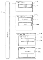
도 1은 본 실시 형태에 관한 약제 불출 장치의 개략 사시도이다.
도 2는 도 1에서 카세트를 인출한 상태를 도시하는 일부 확대 사시도이다.
도 3은 도 1의 약제 수취 유닛을 도시하는 사시도이다.
도 4는 도 3의 바닥면도이다.
도 5는 도 1의 약제 저류 부재를 상방으로부터 본 상태를 도시하는 사시도이다.
도 6은 도 1의 약제 저류 부재를 하방으로부터 본 상태를 도시하는 사시도이다.
도 7은 본 실시 형태에 관한 약제 불출 장치의 블록도이다.
도 8은 본 실시 형태에 관한 약제 불출 장치의 동작을 도시하는 흐름도이다.
도 9는 도 8의 불출 수량 연산 처리를 도시하는 흐름도이다.
도 10은 도 8의 약제 불출 처리를 도시하는 흐름도이다.
도 11은 다른 실시 형태에 관한 약제 수취 유닛을 정면측으로부터 본 상태를 도시하는 사시도이다.
도 12는 다른 실시 형태에 관한 약제 수취 유닛의 측면도이다.
도 13은 다른 실시 형태에 관한 약제 수취 유닛을 배면측으로부터 본 상태를 도시하는 사시도이다.
도 14는 도 11에 도시하는 약제 수용부의 동작 예를 나타내는 설명도이다.
도 15는 도 11에 도시하는 약제 수용부의 다른 동작 예를 나타내는 설명도이다.
도 16은 도 11에 도시하는 약제 수용부의 다른 동작 예를 나타내는 설명도이다.
도 17은 다른 실시 형태에 관한 약제 저류 부재 및 그 주변 부재를 도시하는 사시도이다.
도 18은 도 17의 평면도이다.
도 19는 도 17의 정면도이다.
도 20은 도 17의 우측 2 군데의 방향 변환 용기의 동작을 도시하는 개략 설명도이다.
도 21은 도 20의 방향 변환 용기의 회전 동작을 행하기 위한 기구를 설명하는 도면이다.
도 22는 다른 실시 형태에 관한 약제 저류 부재 및 그 주변 부재를 도시하는 사시도이다.
도 23은 도 22의 배면측으로부터 본 상태를 도시하는 사시도이다.
도 24는 도 22의 측면도이다.
도 25는 다른 실시 형태에 관한 약제 수용 용기로부터의 약제 불출 기구를 도시하는 불출 부재의 측면도이다.
도 26은 다른 실시 형태에 관한 약제 수취 유닛의 개략 사시도이다.
도 27은 도 26의 약제 수취 유닛에 의한 약제 저류 부재로의 약제의 불출 동작을 도시하는 설명도이다.
도 28의 (a)는 도 26의 약제 수취 유닛의 평면도, (b)는 바닥면도, (c)는 배면도이다.
도 29는 도 26의 약제 수취 유닛에 의한 좌열의 약제 수용 용기로부터 약제를 불출할 때의 동작을 도시하는 도면이다.
도 30은 도 26의 약제 수취 유닛에 의한 우열의 약제 수용 용기로부터 약제를 불출할 때의 동작을 도시하는 도면이다.1 is a schematic perspective view of a medicine dispensing apparatus according to the present embodiment.
2 is a partially enlarged perspective view showing a state in which the cassette is pulled out in Fig.
Fig. 3 is a perspective view showing the medicine receiving unit of Fig. 1; Fig.
Figure 4 is a bottom view of Figure 3;
Fig. 5 is a perspective view showing a state in which the medicine holding member of Fig. 1 is viewed from above. Fig.
Fig. 6 is a perspective view showing a state in which the medicine holding member of Fig. 1 is viewed from below. Fig.
7 is a block diagram of the medicine dispensing apparatus according to the present embodiment.
8 is a flowchart showing the operation of the medicine dispensing apparatus according to the present embodiment.
9 is a flowchart showing the dispensation quantity calculation process of Fig.
10 is a flowchart showing the medicine dispensing process of FIG.
11 is a perspective view showing a state in which the medicine-receiving unit according to another embodiment is viewed from the front side.
12 is a side view of a medicine receiving unit according to another embodiment.
13 is a perspective view showing a state in which the medicine receiving unit according to another embodiment is viewed from the back side.
14 is an explanatory view showing an example of the operation of the medicine accommodating portion shown in Fig.
Fig. 15 is an explanatory view showing another operation example of the medicine accommodating portion shown in Fig. 11. Fig.
Fig. 16 is an explanatory view showing another operation example of the medicine accommodating portion shown in Fig. 11. Fig.
17 is a perspective view showing a medicine holding member and its peripheral members according to another embodiment.
18 is a plan view of Fig.
19 is a front view of Fig.
Fig. 20 is a schematic explanatory diagram showing the operation of the two directional conversion containers on the right side in Fig. 17;
Fig. 21 is a view for explaining a mechanism for performing the rotating operation of the orientation changing container of Fig. 20;
22 is a perspective view showing a medicine holding member and its peripheral members according to another embodiment;
23 is a perspective view showing the state as viewed from the rear side of Fig.
24 is a side view of Fig.
25 is a side view of a dispensing member showing a medicine dispensing mechanism from a medicine container according to another embodiment;
26 is a schematic perspective view of a medicine receiving unit according to another embodiment.
Fig. 27 is an explanatory view showing the dispensing operation of the medicine to the medicine holding member by the medicine receiving unit of Fig. 26; Fig.
FIG. 28A is a plan view of the medicine receiving unit of FIG. 26, FIG. 28B is a bottom view, and FIG. 28C is a rear view.
Fig. 29 is a diagram showing the operation when the medicine is taken out from the medicament-accommodating container in the left-hand column by the medicament receiving unit in Fig. 26; Fig.
Fig. 30 is a diagram showing the operation when dispensing the medicine from the medicine container of the superiority by the medicine receiving unit of Fig. 26; Fig.
이하, 본 발명에 관한 실시 형태를 첨부 도면을 따라서 설명한다. 단, 이하의 설명에서는, 구성 요소의 종류, 조합, 형상, 상대 배치 등은 특정적인 기재가 없는 한, 본 발명의 기술적 범위를 그것에만 한정하는 것이 아니다. 또한, 적절하게 필요에 따라서 특정 방향이나 위치를 나타내는 용어(예를 들어, 「상」, 「하」, 「전」, 「후」, 「일단부」, 「타단부」 등)를 사용하지만, 그들 용어의 사용은 도면을 참조한 발명의 이해를 쉽게 하기 위해서이며, 그들 용어의 의미에 의해 본 발명의 기술적 범위가 한정되는 것은 아니다.DESCRIPTION OF THE PREFERRED EMBODIMENTS Hereinafter, embodiments of the present invention will be described with reference to the accompanying drawings. It should be noted, however, that the technical scope of the present invention is not limited thereto unless the type, combination, shape, relative arrangement, and the like of the components are described in the following description. Further, although terms (for example, "top", "bottom", "front", "back", "one end", "other end", etc.) The use of the terms is intended to facilitate understanding of the invention with reference to the drawings, and the technical scope of the present invention is not limited by the meanings of the terms.
(1. 전체 구성)(1. Overall configuration)
도 1은 본 실시 형태에 관한 약제 불출 장치를 도시한다. 이 약제 불출 장치는, 프레임(1)에 외부 장착 패널(2)을 장착한 대략 직육면체 형상의 장치 본체(3) 내에, 약제 수용 유닛(4), 약제 수취 유닛(5), 약제 회수 유닛(6) 및, 제어 유닛(7)(도 7 참조)을 각각 설치한 구성이다.Fig. 1 shows a medicine dispensing apparatus according to the present embodiment. This medicine dispensing apparatus is provided with a
[1-1. 약제 수용 유닛(4)][1-1. Drug receiving unit (4)]
약제 수용 유닛(4)은, 도 2에 도시한 바와 같이, 카세트 수용부(8)와, 거기에 착탈되는 복수의 카세트(9)(약제 수용부)를 구비한다. 카세트 수용부(8)는 장치 본체(3)의 내부 공간을 복수의 구획벽(10)에 의해 좌우 방향으로 소정의 간격으로 분할하고, 수평 선반(11)에 의해 다시 상하로 2 분할함으로써 세로로 긴 공간을 형성한 것이다. 구획벽(10)의 대향면에는 홈부(상세하게는 도시하지 않음)이 각각 형성되고, 상하 방향으로 복수의 카세트(9)가 착탈 가능하게 병설되어 있다.2, the
카세트(9)는, 종류별로 복수의 약제가 각각 수용되고, 수용하는 앰플(12)의 사이즈에 따라서 폭 치수 및 높이 치수, 경우에 따라서는 길이(깊이) 치수가 다르다. 여기에서는, 카세트(9) 내에는 약제로서 대략 원통 형상의 앰플(12)이, 그 지름 방향으로 정렬된 상태로 수용되어 있다. 앰플(12)은, 정(定) 하중 스프링(12a)에 의해 약제 불출측으로 압박됨으로써 간극 없이 병설되어 있다. 그리고 약제 배출부를 구성하는 로터(13)를 회전함으로써 1개씩 불출되도록 되어 있다. 로터(13)는, 앰플(12)의 외주면을 따른 오목부(도시하지 않음)를 구비하고 있다. 로터(13)의 회전은, 돌출 방향으로 압박된 로드(14)를 압입하고, 이 로드(14)에 형성된 랙을 통해서 로터(13)의 회전축에 설치한 피니언을 회전시킴으로써 행해진다. 또한, 각 카세트(9)는 로터(13)에 의한 배출 위치가 임의의 기준면[장치 본체(1)의 전방면에 평행한 면]에 대하여 평행해지도록 배치되어 있다. 또한, 카세트(9)에는 로터(13) 측의 상하 테두리부에 절결부(도시하지 않음)를 형성하고, 장치 본체(1)의 각 열마다 상하에 설치한 광 센서(1a) 및 반사판(1b)에 의해 절결 부분으로 앰플(12)이 불출되고 있는지의 여부를 검출하도록 하는 것이 바람직하다. 이에 따르면, 로터(13)가 회전해서 앰플(12)이 불출되면, 이 앰플(12)에 의해 절결 부분으로 조사광이 차단되어 광 센서(1a)에 수광되지 않게 되므로, 불출된 것을 확실하게 검출할 수 있다. 그리고 로터(13)를 회전시켜서 앰플(12)을 불출했음에도 광 센서(1a)로 수광된 상태이면, 후술하는 돌출 동작을 반복해서 로터(13)를 회전시킨다. 그런데도 센서로 수광된 상태이면, 에러라는 취지를 통지하도록 하면 좋다. 카세트(9)에 형성한 절결 부분에서 앰플(12)의 유무를 검출하므로, 손가락이나 약제 수취 유닛(5) 등에 의해 잘못 검출하는 등의 염려가 없다. 또한, 광 센서(1a) 및 반사판(1b)에 의해 카세트(9)의 삽입 발출 상태도 검출하도록 해도 좋다.Each of the
[1-2. 약제 수취 유닛(5)][1-2. Medicament Receiving Unit (5)]
약제 수취 유닛(5)은, 장치 본체(3)의 전방면측 프레임(1)[좌우 한 쌍의 수직 레일(15)]에, 상하(수직) 방향으로 왕복 이동 가능하게 부착된 수평 레일(16)과, 이 수평 레일(16)에 좌우(수평) 방향으로 왕복 이동 가능하게 부착한 슬라이드 베이스(17)를 구비한다. 슬라이드 베이스(17)에는, 돌출 유닛(18)과 약제 수취 용기(19)가 설치되어 있다.The
돌출 유닛(18)은, 돌출 베이스(20)에 돌출 모터(21)와 돌출 핀(22)을 설치한 것이다. 돌출 베이스(20)는 역 U자형이고, 돌출 핀(22)은 그 일단부측에 설치되어 있다. 돌출 핀(22)은, 돌출 모터(21)에 의해 도시하지 않은 피니언과 랙을 통해서 왕복 이동하고, 상기 약제 수용 유닛(4)에 설치한 로드(14)를 압입함으로써, 앰플(12)을 1개씩 불출시킨다.The protruding
약제 수취 용기(19)는, 도 3 및 도 4에 도시한 바와 같이, 정면판(23)의 양단부 및 중앙부에 각각 측판(24) 및 중앙판(25)을 각각 일체화하고, 둘러싸인 2개의 영역[제1 약제 수취부(26a) 및 제2 약제 수취부(26b)]의 바닥면 부분에 바닥판(27)을 각각 배치한 것이다. 도 3에 도시한 바와 같이, 바닥판(27)의 상면에는 탄성 시트(31)가 배치되어 있다. 바닥판(27)은 상기 지지축(28a)을 중심으로 해서 회전하고, 바닥면을 폐쇄한 상태에서는 정면판(23)을 향해 서서히 하방측으로 경사져 있다. 이에 의해, 카세트(9)로부터 불출된 앰플(12)이 원활하게 각 약제 수취부(26a, 26b)에 수용된다. 또한, 각 바닥판(27)은 지지축(28a)에 고정한 풀리(28b)에 걸친 벨트(28c)를 통해서 정면판(23)의 전방면에 설치한 모터(28d)로부터의 동력이 전달됨으로써, 동기 회전하여 바닥면을 개폐시키도록 되어 있다. 그리고 약제 수취 용기(19)는, 슬라이드 베이스(17)에 대하여 수평 이동하여, 카세트(9) 즉 돌출 유닛(18)의 돌출 베이스(20)에 대하여 각 약제 수취부(26a, 26b)가 각각 위치 결정된다.3 and 4, the
[1-3. 약제 회수 유닛(6)][1-3. Drug recovery unit (6)]
약제 회수 유닛(6)은, 약제 저류 부재(32)와, 그 하방측에 배치되어, 반송 부재(33)에 의해 반송되는 약제 회수 용기(34)를 구비한다.The
약제 저류 부재(32)는, 도 5 및 도 6에 도시한 바와 같이, 장치 본체(3)에 고정되는 지지부(35)와, 이 지지부(35)에 의해 지지되어 승강 가능한 본체부(36)를 구비한다. 본체부(36)는, 지지부(35)에 설치한 모터(도시하지 않음)의 구동에 의해 승강한다. 본체부(36)에는, 4개의 약제 저류부(37)가 설치되어 있다. 각 약제 저류부(37)의 바닥면은, 제1 경사판(38)과 제2 경사판(39)으로 구성되어 있다. 제1 경사판(38)은 본체부(36)에 고정되어 있고, 중간 부분에서 굴곡되어 있다. 제1 경사판(38)의 하반부에는 복수의 브러시(40)가 일체화되어, 선단부로부터 돌출하고 있다. 제2 경사판(39)은, 모터(39a)의 구동에 의해 지지축(39b)을 중심으로 해서 회전 가능하게 설치되어 있다. 각 지지축(39b)에는 풀리(39c)가 고정되고, 풀리(39c) 사이에 걸친 벨트(39d)를 통하여, 제2 경사판(39)은 동기 회전하도록 되어 있다. 제2 경사판(39)은, 상기 약제 수취 용기(19)의 바닥판(27)과 같은 구성으로, 힌지(38a)에 의해 회전 가능하게 연결된 제1 경사부(41)와 제2 경사부(42)로 구성되어 있다. 또한, 제1 경사판(38)과 제2 경사판(39)의 상면에는 각각 탄성 시트(43)가 적재되어 있다. 또한, 제2 경사판(39)을 중심측에 배치하면, 약제 회수 용기(34)의 각 약제 회수부(44) 내에 확실하게 앰플을 배출할 수 있게 된다. 또한, 제1 경사판(38)을 약제 회수부(44)의 위치에 맞춰서 내측으로 경사지게 함으로써, 앰플(12)의 수취량을 많게 할 수 있다. 이에 의해, 약제 회수 용기(34)에 대하여 약제 저류 부재(32)를 크게 할 수 있으므로, 앰플(12)의 저류량을 증대시킬 수 있게 된다.5 and 6, the
반송 부재(33)는, 도시하지 않은 모터에 의해 구동하는 반송 벨트(33a)를 구비하고, 장치 본체(3) 내에 약제 회수 용기(34)를 반입하여, 회수 위치에서 일단 정지시킨 후, 외부로 반출한다.The conveying member 33 is provided with a
약제 회수 용기(34)는, 내부가 구획판(34a)에 의해 4 분할됨으로써 약제 회수부(44)가 각각 형성되어 있다. 이것은, 환자 1명의 1일 최대 처방 수(아침, 점심, 저녁, 밤)에 맞춘 것이다. 각 약제 회수부(44)의 크기는, 상기 약제 저류 부재(32)의 각 약제 저류부(37)에 대응하고 있다.The
[1-4. 제어 유닛(7)][1-4. Control unit 7]
제어 유닛(7)은, 도 7에 도시한 바와 같이, 호스트 컴퓨터 등으로부터 입력된 처방 데이터를 기초로 하여, 각종 모터 등을 구동 제어함으로써, 약제 수취 용기(19)를 이동시킨다. 그리고 약제 수용 유닛(4)의 카세트(9)로부터 해당하는 약제를 불출시켜 회수하고, 약제 저류 부재(32)를 통해서 약제 회수 용기(34)로 약제를 회수시킨다. 그 후, 약제 회수 용기(34)를 이동시켜서 회수한 약제를 반출한다.As shown in Fig. 7, the
(2. 동작)(2nd operation)
다음에, 상기 구성으로 이루어지는 약제 불출 장치의 동작을 도 8에 도시하는 흐름도를 따라서 설명한다.Next, the operation of the medicine dispensing apparatus having the above configuration will be described with reference to the flowchart shown in Fig.
우선, 처방 데이터를 기초로 하여, 약제의 불출 명령이 있는지의 여부를 판단한다(스텝 S1). 불출 명령이 있으면, 약제의 불출 수량을 연산 처리한다(스텝 S2).First, based on the prescription data, it is determined whether or not there is an instruction to dispense medicine (step S1). If there is a dispense instruction, the dispensed quantity of medicine is calculated (step S2).
약제의 불출 수량의 연산 처리에서는, 도 9에 도시한 바와 같이, 약제 수취 용기(19)의 어떤 약제 수취부(26)에 약제를 불출할지를 결정한다(스텝 S21). 여기에서는, 약제 수취부(26)는 2개이므로, 처음에 제1 약제 수취부로 결정하고, 후술하는 스텝 S27에서 제2 약제 수취부로 변경한다.In the calculation processing of the dispensed quantity of the medicine, as shown in Fig. 9, it is determined which
제1 약제 수취부로 결정되면, 불출 수량을 초기화(n = 0)(스텝 S22)하여, 불출 수량 Y(i)가 미불출 수량 X 미만인지의 여부를 판단한다(스텝 S23). 그리고 불출 수량 Y(i)가 미불출 수량 X에 도달하는지, 혹은 다음 식을 만족할 때까지(스텝 S24), 약제의 불출 수량을 가산(n + 1) 한다(스텝 S25).(N = 0) (step S22), and it is determined whether or not the dispensed quantity Y (i) is less than the dispensed quantity X (step S23). (Step S25) until the dispensed quantity Y (i) reaches the dispensed quantity X or the following equation is satisfied (step S24).
[수학식 1][Equation 1]
T ≤ A ― (T × n + Z)T? A - (Txn + Z)
A : 약제 수취부(26)의 총 용량(수취 한계량)A: total capacity of the medicine receiving portion 26 (receiving limit amount)
T : 약제 사이즈T: Pharmaceutical size
n : 약제의 불출 가정 수량(개수)n: Quantity of dispensed medicines (number)
Z : 약제 수취부(26)의 초기 용량Z: Initial capacity of the
이와 같이 하여, 불출 수량 Y(i)를 가산하여, 그 값이 미불출 수량 X를 초과하는지, 혹은 불출 수량 Y(i)가 미불출 수량 X 미만이라도 상기 수학식 1을 만족하지 않아, 제1 약제 수취부에는 더 이상 약제를 수용할 수 없다고 판단되면, 불출 수량 Y(i)를 가산하기 전의 현재의 불출 수량(n)으로 결정한다(스텝 S26). 그리고 약제를 불출하는 약제 수취부(26)를 다음의 제2 약제 수취부로 변경한다(스텝 S27).In this way, even if the dispensed quantity Y (i) is added and the value exceeds the dispensed quantity X or the dispensed quantity Y (i) is less than the dispensed quantity X, the above formula (1) If it is determined that the medicine can not be accommodated any more, the medicine dispenser determines the dispensed quantity Y (i) as the current dispensed quantity n before addition (step S26). Then, the
이하, 마찬가지로 하여 상기 스텝 S21에서 S27을, 제2 약제 수취부로의 약제의 불출 수량이 연산될 때까지 속행한다(스텝 S28).Subsequently, similarly, steps S21 to S27 are continued until the dispensed quantity of medicine to the second medicine receiving section is calculated (step S28).
약제의 불출 수량이 연산되면, 약제를 불출 가능한 약제 수취부(26)가 있는지의 여부를 판단하고(스텝 S3), 불출 가능한 약제 수취부(26)가 있으면, 그 약제 수취부(26)를 해당하는 카세트(9)로 이동시킨다(스텝 S4). 여기에서는, 약제 수취 용기(19)를 이동시켜서, 제1 약제 수취부(26a)를 해당하는 약제가 수용된 카세트(9)로부터 불출 가능한 위치에 위치 결정한다. 그리고 돌출 유닛(18)의 돌출 핀(22)을 돌출시킴으로써, 약제 수용 유닛(4)에 설치한 로드(14)를 압입하고, 로터(13)를 회전시켜서 약제를 1개씩 불출시킨다. 이렇게 해서, 상기 스텝 S2에서 미리 연산된 수량의 약제를 카세트(9)로부터 약제 수취부(26)로 불출한다(스텝 S5). 약제의 불출이 완료되면, 불출 수량을 기초로 하여 미불출 수량을 갱신한다(스텝 S6).When the dispensed quantity of the medicine is calculated, it is judged whether or not the
이하 마찬가지로 하여, 스텝 S3에서, 약제를 불출 가능한 약제 수취부(26)가 없어질 때까지, 상기 스텝 S4 내지 S6의 처리를 속행한다. 여기에서는, 제1 약제 수취부(26a)와 제2 약제 수취부(26b)의 양쪽에, 연산된 불출 수량이 전부 불출될 때까지, 카세트(9)로부터 각 약제 수취부(26)로의 약제 불출을 속행한다. 또한, 카세트(9)로부터 제2 약제 수취부로 약제를 불출할 경우, 돌출 유닛(18)이 제1 약제 수취부(26a) 측에 설치되어 있으므로, 약제 수취 용기(19)를 미끄럼 이동시켜서, 제2 약제 수취부(26b)를 돌출 유닛(18)에 위치 결정한다.Likewise, the processing in steps S4 to S6 is continued until, at step S3, the medicament
또한, 복수 종류의 약제를 제1 약제 수취부(26a)와 제2 약제 수취부(26b)로 불출할 경우, 그 불출 순서는 자유롭게 설정할 수 있다. 예를 들어, 제1 약제 수취부(26a)로 A 약제를 1개 불출하고, 제2 약제 수취부(26b)로 A 약제를 1개, B 약제를 1개 불출할 경우, 제1 약제 수취부(26a)로 A 약제를 불출한 후, 제2 약제 수취부(26b)에서 A 약제가 아닌, 먼저 B 약제를 1개 불출하도록 해도 좋다. 또한, 제1 약제 수취부(26a)로 A 약제를 1개, B 약제를 1개 불출하고, 제2 약제 수취부(26b)로 A 약제를 1개 불출할 경우, 제1 약제 수취부(26a)로 A 약제를 1개 불출한 후, 제2 약제 수취부(26b)로 A 약제를 1개 불출하기 전에, 먼저 제1 약제 수취부(26a)로 B 약제를 1개 불출하도록 해도 좋고, 제1 약제 수취부(26a)보다도 먼저 제2 약제 수취부(26b)에서 A 약제를 1개 불출하도록 해도 좋다. 또한, 1개의 약제 수취부(26)에서 약제의 수취 동작을 행하는 경우에 대해서 설명한다. 예를 들어, 약제 수취부(26)의 수취 한계량이 10이고, 사이즈가 3인 A 약제를 6개, 사이즈가 2인 B 약제를 6개 불출할 경우, 약제 수취부(26)로 A 약제를 3개 불출하면, 이 약제 수취부(26)로는 더 이상의 약제 불출은 무리이다. 그래서, 일단 약제 수취부(26)로부터 약제 저류 부재(32)로 A 약제를 배출한다. 그리고 다시, 약제 수취부(26)를 이동시켜, A 약제를 3개 불출하는 2회째의 불출 동작을 실행한다. 계속해서, 3회째의 불출 동작에서, 약제 수취부(26)로 B 약제를 5개 불출하고, 4회째의 불출 동작에서, 약제 수취부(26)에 남은 1개의 B 약제를 불출한다. 이에 따르면, 불출 동작이 4회가 된다. 이에 대해, A 약제 2개와 B 약제 2개의 4개를 1 세트로 하여 불출하도록 하면, 3회의 불출 동작으로 종료할 수 있다.When a plurality of kinds of medicines are dispensed to the first
제1 약제 수취부(26a)와 제2 약제 수취부(26b)로의 약제 불출이 완료되면, 약제 수취 용기(19)를 약제 저류 부재(32)로 이동시켜, 불출한 약제를 전부 대응하는 각 약제 저류부(37)로 배출시킨다(스텝 S7). 여기에서는, 약제 저류 부재(32)의 제1 약제 저류부에 제1 약제 수취부(26a)를 위치 결정하고, 제2 약제 저류부에 제2 약제 수취부(26b)를 위치 결정한다. 그리고 바닥판(27)을 회전시켜서 바닥면을 개방하고, 약제를 각 약제 수취부(26)로부터 대응하는 각 약제 저류부(37)로 2 군데에서 동시에 배출한다. 이때, 각 약제 수취부(26)의 수용 수량을 리셋(= 0)한다.When the dispensing of the medicine into the first
상기 스텝 S1에서, 불출 명령이 없으면, 약제 수취 용기(19)의 각 약제 수취부(26)에 약제가 잔류하고 있는지의 여부를 판단한다(스텝 S8). 이 판단은, 예를 들어 카세트(9)로부터 약제 수취부(26)로 약제가 불출된 후, 그 약제 수취부(26)로부터 약제 저류 부재(32)로 약제가 불출되었는지의 여부에 의해 행하면 좋다. 약제 수취부(26)에 약제가 잔류되어 있으면, 약제 수취 용기(19)를 이동시켜, 약제 저류 부재(32)의 각 약제 저류부(37) 중, 남은 2 군데로 이동시켜 약제를 배출시킨다(스텝 S9). 이때, 상기와 마찬가지로, 각 약제 수취부(26)의 수용 수량을 리셋(= 0)한다. 그 후, 약제를 약제 저류 부재(32)로부터 약제 회수 용기(34)로 불출하는 불출 처리를 실행한다(스텝 S10).In step S1, if there is no dispense instruction, it is determined whether or not the medicine remains in each
불출 처리에서는, 도 10의 흐름도에 도시한 바와 같이, 우선 약제 저류 부재(32)의 모든 약제 저류부(37)에 약제가 저류되었는지의 여부를 판단한다(스텝 S31). 약제의 저류가 완료되면, 그 하방의 배출 위치에 약제 회수 용기(34)가 위치 결정될 때까지 대기한다(스텝 S32). 그리고 배출 위치에 약제 회수 용기(34)가 위치 결정되면, 약제 저류 부재(32)를 강하시킨다(스텝 S33). 계속해서, 도시하지 않은 강하 위치 검출 센서에 의해 약제 저류 부재(32)가 배출 위치 근방의 배출 준비 위치까지 강하된 것이 검출되면(스텝 S34), 약제 저류 부재(32)를 정지시켜서 제2 경사판(39)을 회전시킴으로써 바닥면을 개방한다(스텝 S35). 제2 경사판(39)의 회전은, 도시하지 않은 개방 위치 검출 센서에 의해 검출될 때까지 행한다(스텝 S36). 이에 의해, 저류된 약제가 일제히 약제 회수 용기(34)의 각 약제 회수부(44)로 불출된다. 그 후, 제2 경사판(39)이 소정 위치까지 회전하면, 약제 저류 부재(32)를 배출 대기 위치로 상승시켜(스텝 S37), 도시하지 않은 대기 위치 검출 센서에 의해 약제 저류 부재(32)가 검출되면(스텝 S38), 약제 저류 부재(32)의 상승을 정지하고, 제2 경사판(39)을 회전시켜서 바닥면을 폐쇄한다(스텝 S39). 또한, 약제가 불출된 약제 회수 용기(34)는 다음 공정으로 반출하고, 다음의 약제 회수 용기(34)를 반입한다.In the dispensing process, as shown in the flowchart of Fig. 10, first, it is judged whether or not the medicines are stored in all the
이와 같이, 상기 실시 형태에 관한 구성에 따르면, 한 쌍의 약제 수취부(26)를 인접한 상태에서, 상하 및 좌우로 이동만 시키면 되므로, 구성을 간략화해서 저렴하게 제작할 수 있다. 또한, 돌출 유닛(18)에 대하여 약제 수취 용기(19)를 수평 방향으로 이동시킴으로써, 각 약제 수취부(26)에서 돌출 유닛(18)을 겸용하도록 했으므로, 고속으로 확실하게 약제를 불출할 수 있다. 특히, 동일한 카세트(9)로부터 약제를 연속해서 불출하는 경우에 유효하다. 또한, 약제 회수 용기(34)의 근방에 배치한 약제 저류 부재(32)에, 일단 약제를 저류하고, 동시에 저류한 약제를 약제 회수 용기(34)로 배출할 수 있으므로, 신속한 불출 동작이 가능해지는 동시에, 약제인 앰플(12)에 깨짐 등의 문제가 발생하는 일도 없다.As described above, according to the configuration according to the above embodiment, since the pair of
(3. 다른 실시 형태)(3. Other Embodiments)
또한, 본 발명은, 상기 실시 형태에 한정되는 것은 아니며, 특허청구의 범위에 기재된 기술적 사항의 범위 내에 있어서 다양한 변경 등이 가능하다.The present invention is not limited to the above-described embodiments, but may be modified in various ways within the scope of the technical matters described in the claims.
상기 실시 형태에서는, 약제를 약제 수취 용기(19)로부터 약제 회수 용기(34)로 불출하기 전에, 일단 약제 저류 부재(32)에 저류시키도록 했지만, 이 약제 저류 부재(32)는 반드시 필요한 것은 아니며, 약제 수취 용기(19)로부터, 직접 약제 회수 용기(34)의 각 약제 회수부(44)로 약제를 불출하도록 해도 좋다.Although the medicine is temporarily stored in the
약제 수취 용기(19)는, 한 쌍의 약제 수취부(26)를, 인접한 상태에서 상하 및 좌우로 이동시키도록 구성했지만, 각 약제 수취부(26)를 개별로 상하 및 좌우로 이동시키도록 해도 좋다. 이에 따르면, 한쪽 약제 수취부(26)에서, 어떤 카세트(9)로부터 한창 약제를 수취하고 있는 중에, 다른 쪽 약제 수취부(26)에서 다른 카세트(9)(약제가 동일한지의 여부를 묻지 않음)로부터 약제를 받을 수 있어, 한층 더 고속으로 약제의 불출 처리를 행할 수 있게 된다.The
(3-2. 제3 실시 형태)(3-2 Third Embodiment)
상기 실시 형태에서는, 약제 수취 유닛(5)을 2개의 약제 수취부(26)로 이루어지는 약제 수취 용기(19)를 구비한 구성으로 했지만, 예를 들어 도 11에 도시한 바와 같이, 2개의 약제 수취부(26)로 이루어지는 약제 수취 용기(19)를 2개 구비한 구성으로 하는 것도 가능하다.In the above embodiment, the
즉, 약제 수취 유닛(5)은 상기와 마찬가지로 장치 본체(3)의 전방면측의 좌우 한 쌍의 수직 레일(15)과, 수직 레일(15)에 상하 방향으로 왕복 이동 가능하게 설치한 수평 레일(16)과, 이 수평 레일(16)에 좌우로 이동 가능하게 설치한 슬라이드 베이스(17)를 구비한다. 그리고 슬라이드 베이스(17)에는 각 약제 수취 용기(19)를 좌우 방향으로 구동하기 위한 수평 구동 기구가 설치되어 있다.That is, the
수평 구동 기구는, 한 쌍의 풀리(100)(한쪽은 도시하지 않음) 사이에 벨트(101)를 걸친 것으로, 한쪽 풀리(100)가 모터(102)의 구동에 의해 정역(正逆) 회전하도록 되어 있다. 또한, 벨트(101)에는 연결부(103)를 통해서 각 약제 수취 용기(19)가 각각 연결되어 있다. 연결 위치는, 각 약제 수취 용기(19)가 중앙에서 상하로 겹친 위치 관계에 있으면, 벨트(101)의 각 직선부의 중앙 부분이다. 이 상태로부터, 모터(102)를 정역 회전 구동시키면, 각 약제 수취 용기(19)가 좌우로 왕복 이동하도록 되어 있다.The horizontal driving mechanism includes a pair of pulleys 100 (one of which is not shown) and a
또한, 슬라이드 베이스(17)의 하면에는 돌출 유닛(45)이 부착되어 있다. 돌출 유닛(45)은 천장판(46)과, 그 양단부로부터 하방으로 연장되는 양측판(47)과, 천장판(46)의 중앙부 하면으로부터 하방으로 연장되어 양측면을 구획하는 구획판(48)을 구비한다. 구획판(48)에 의해 구획된 2개의 영역의 천장판(46)에는 모터(50a)가 각각 설치되어 있다. 각 모터(50a)는, 도시하지 않은 랙과 피니언에 의해 돌출 핀(50)을 각각 진퇴시킬 수 있게 되어 있다.Further, a protruding
돌출 유닛(45)의 양측면에는 수직 구동 기구가 설치되어 있다. 수직 구동 기구는, 돌출 유닛(45)의 양측판(47)으로부터 각각 하방으로 연장하는 한 쌍의 제1 슬라이더(52)와, 각 제1 슬라이더(52)에 상하 방향으로 슬라이드 가능하게 설치한 대략 U자형의 제2 슬라이더(53)를 구비한다. 돌출 유닛(45)의 천장판(46)의 양단부 상부와, 양측판(47)에는 풀리(110)가 각각 설치되어 있다. 일단부 상하에 위치하는 풀리(110)와 타단부 상하에 위치하는 풀리(110)에는 벨트(111)가 각각 걸쳐져 있다. 상방측에 위치하는 풀리(110)끼리는 지지축(112)에 의해 연결되고, 일단부 하방측에 위치하는 풀리(110)가 모터(113)의 구동에 의해 회전하도록 되어 있다. 각 벨트(111)에는, 연결부(114)를 통해서 각 약제 수취 용기(54)가 각각 연결되어 있다. 연결 위치는, 전후에 위치하는 벨트(111)의 각 직선부이다. 따라서, 모터(113)를 정역 회전 구동하면, 풀리(110) 및 벨트(111)를 통해서 제2 슬라이더(53)가 승강하고, 각 약제 수취 용기(19)가 상반하는 상하 방향으로 이동한다.On both sides of the protruding
약제 수취 용기(19)를 구성하는 각 약제 수취부(55)는, 대략 U자형의 프레임(56)과, 프레임(56)의 바닥면 및 한쪽 측면을 덮는 바닥판(57)으로 구성되어 있다. 각 바닥판(57)은, 동일한 지지축(57a)을 중심으로 해서 회전 가능하게 설치되고, 모터(120)(예를 들어, 스테핑 모터)의 정역 회전 구동에 의해 풀리(121) 및 벨트(122)를 통해서 동력이 전달되도록 되어 있다. 이에 의해, 각 약제 수취부(26)의 바닥면은 동기해서 바닥면 및 측면을 폐쇄 또는 개방한다.Each medicine receiving portion 55 constituting the
상기 약제 수취 유닛(5)은, 2개의 약제 수취부로 이루어지는 약제 수취 용기(19)를 2개 구비하여, 약제 수취 용기 단위로, 도 14의 (a)에서 (i)에 도시한 바와 같이, 상하 좌우로 이동시킨다.The
즉, 도 14의 (a)에 도시한 바와 같이, 제3 및 제4 약제 수취부(26c 및 26d)와, 제1 및 제2 약제 수취부(26a 및 26b)가 상하로 겹친 위치로부터, 각 세트를 좌우로 이동시킨다. 그리고 도 14의 (b)에 도시한 바와 같이, 상하 방향에는 서로 겹치지 않는 위치에 이르면, 도 14의 (c)에 도시한 바와 같이, 제1 및 제2 약제 수취부(26a 및 26b)를 상방으로 이동시켜, 각 약제 수취부(26a 내지 26d)를 이 순서로 일렬로 정렬시킨다. 또한, 제1 및 제2 약제 수취부(26a 및 26b)와, 제3 및 제4 약제 수취부(26c 및 26d)의 좌우 위치를 변경할 경우에는, 도 14의 (d), (e)의 동작을 행하게 해서 원래의 위치로 복귀시킨 후, 도 14의 (f), (g)에 도시한 바와 같이, 전술한 것과는 반대의 동작을 행하게 하면 좋다. 그리고 도 14의 (h), (i)의 동작으로 원래의 위치로 복귀시키면 좋다. 이와 같이, 2개의 약제 수취부(26a, 26b 또는 26c, 26d)로 이루어지는 약제 수취 용기(19) 단위로 상하 좌우로 이동시킴으로써, 카세트(9)로부터 불출하는 약제를 어떠한 약제 수취부(26a 내지 26d)라도 수취할 수 있다.That is, as shown in Fig. 14 (a), from the position where the third and fourth medicament receivers 26c and 26d and the first and
상기 약제 수취 유닛(5)의 이동은, 다음과 같이 구성해도 좋다.The movement of the
즉, 도 15에 도시한 바와 같이, 4개의 약제 수취부를 단부로부터 순서대로, 제1 내지 제4 약제 수취부(55a 내지 55d)(도면 중, 동그라미로 1에서 4의 숫자로 나타냄)라 하고, 중앙에 위치하는 제2 약제 수취부(55b) 및 제3 약제 수취부(55c)에 대하여, 제1 약제 수취부(55a)와 제4 약제 수취부(55d)를 상하 좌우로 이동 가능하게 한다. 도면 중, 돌출 핀(50)의 위치를 삼각형으로 나타낸다. 카세트(9)로부터 제2 약제 수취부(55b) 및 제3 약제 수취부(55c)로 약제를 불출할 경우, 도 15의 (a)에 도시한 바와 같이, 각 약제 수취부(55a 내지 55d)를 위치 결정한다. 그리고 도 15의 (a)에 도시한 상태로부터, 도 15의 (b)에 도시한 바와 같이, 제1 약제 수취부(55a) 및 제4 약제 수취부(55d)를 하방으로 이동시켜, 서로 접근하는 방향으로 이동시킴으로써, 제2 약제 수취부(55b) 및 제3 약제 수취부(55c)의 하방에 위치시킨다. 그 후, 이들 약제 수취부(55a 내지 55d)의 전부를 상방으로 이동시켜, 돌출 핀(50)을 이용해서 카세트(9)로부터 불출하는 약제를 제1 약제 수취부(55a) 및 제4 약제 수취부(55d)에 의해 수취 가능하게 한다.That is, as shown in Fig. 15, the four medicament receiving portions are referred to as first to fourth
또한, 상기 약제 수취 유닛(5)에서는, 도 16에 도시한 바와 같이, 4개의 약제 수취부(55a 내지 55d)(도면 중, 동그라미로 1에서 4의 숫자로 나타냄)를 이동 가능하게 구성해도 좋다. 예를 들어, 도 16에 도시한 바와 같이, 제1 약제 수취부(55a)와 제2 약제 수취부(55b)를 링크에 의해 회전 가능하게 연결한다. 또한, 제3 약제 수취부(55c)와 제4 약제 수취부(55d)를 링크에 의해 회전 가능하게 연결한다. 그리고 양자의 링크를 링크에 의해 회전 가능하게 연결한다. 이에 의해, 도 16에 도시하는 다양한 배치 패턴으로 각 약제 수취부(55a 내지 55d)를 배치할 수 있다. 장착된 양측 및 상하로 정렬되는 카세트(9), 특히 4 구석의 카세트(9)라도, 어느 하나의 약제 수취부(55a 내지 55d)로 약제를 불출할 수 있도록, 각 약제 수취부(55a 내지 55d)의 배치 패턴을 변경할 수 있다.In addition, in the
또한, 상기 약제 수취부(26)의 수는 2 또는 4에 한정되지 않으며, 3 또는 5 이상이라도 상관없다.Further, the number of the
또한, 상기 약제 수취 유닛(5)과 약제 저류 부재(32) 사이에는, 약제 저류 부재(32)로의 약제의 전달을 원활하게 행할 수 있도록, 별도로 약제의 방향을 변환하기 위한 방향 변환 용기(61)를 설치하는 것이 바람직하다.A
즉, 방향 변환 용기(61)는, 도 17에 도시한 바와 같이, 한쪽 측연부의 일단부에 설치한 지지축(62)을 중심으로 하여, 수평면 내를 약제 회수 용기(34)의 반송 방향(도면 중, 우측 방향)을 따른 횡 방향 위치와, 이에 직교하는 종 방향 위치와의 사이의 약 90도의 범위에서 회전한다.That is, as shown in Fig. 17, the orientation-changing
방향 변환 용기(61)의 바닥판(61a)은, 하나의 측연부의 회전축(도시하지 않음)을 중심으로 해서 회전 가능하게 설치되어 있다. 바닥판(61a)은, 지지 플레이트(63)의 상면에 의해 지지되어 폐쇄 상태를 유지하고, 약제 저류 부재(32)에 이름으로써 상면의 지지를 잃고 자중에 의해 개방한다. 또한, 바닥판(61a)은 약제 저류 부재(32)로부터 지지 플레이트(63)의 상면에 이름으로써 바닥면이 압박되어 자동적으로 폐쇄 상태로 복귀한다.The
상기 지지축(62)에는 제1 캠(64)이 일체화되고, 제2 캠(65), 종동 기어(66) 및 구동 기어(67)를 통해서 모터(68)로부터의 동력이 전달되도록 되어 있다.The
제1 캠(64)은, 지지축(62)으로부터 양측으로 연장하는 제1 아암부(69)와, 이 제1 아암부(69)와는 직교하는 방향으로 연장되는 제2 아암부(70)를 구비한다. 제2 아암부(70)의 중앙에는 선단부로부터 절결 홈(71)이 형성되어 있다. 또한, 제2 아암부(70)의 양측부에는, 제1 아암부(69)를 향해 제1 원호면(72)이 각각 형성되어 있다.The
제2 캠(65)은, 제1 캠(64)의 근방에 지지축(73)을 중심으로 해서 회전 가능하게 설치되어 있다. 제2 캠(65)은 대경부(74)와, 그 중앙부에 일체화한 소경부(75)로 구성되어 있다. 소경부(75)는, 그 외주면이 제1 캠(64)의 제1 원호면(72)에 미끄럼 접촉하여, 제1 캠(64)의 회전 위치를 규제한다. 또한, 소경부(75)에는 대칭인 위치 2 군데에 제2 원호면(76)이 각각 형성되어 있다. 대경부(74)에는 소경부(75)의 한쪽 제2 원호면(76)을 2분하는 외주측의 위치에 돌기(77)가 형성되어 있다. 이 돌기(77)는, 제1 캠(64)의 절결 홈(71)에 결합 분리되어, 결합 상태에서 제1 캠(64)을 제2 캠(65)과 연동해서 회전 가능하게 한다. 또한, 대경부(74)의 외주부에는 기어(도시하지 않음)가 형성되어 있다.The
종동 기어(66)는, 대경 기어(78)와, 도시하지 않은 소경 기어로 이루어진다. 소경 기어에는, 상기 제2 캠(65)의 대경부(74)에 형성한 기어(도시하지 않음)와 맞물려져 있다.The driven
구동 기어(67)는, 모터(68)의 회전축에 일체화되어, 종동 기어(66)와 맞물려 있다. 구동 기어(67)에는, 인접해서 배치한 2개의 방향 변환 용기(61)의 각 종동 기어(66)가 맞물려져 있으며, 구동 기어(67)를 통해서 양 방향 변환 용기(61)를 동기 회전시킬 수 있게 되어 있다.The
상기 방향 변환 용기(61)에서는, 인접하는 2 군데에서, 회전 개시 시기가 벗어나 회전하도록 되어 있다(이하, 도 17 중, 우측 2 군데 중, 좌측 부재에 첨자 A를, 우측 부재에 첨자 B를 부여함). 즉, 도 21의 (a)에 도시한 바와 같이, 제2 캠(65A, 65B)은, 한쪽 소경부(75A)와 다른 쪽 소경부(75B)의 위치 관계를 회전 방향으로 90도 벗어난 것으로 한다. 이에 의해, 모터(68)를 구동해서 구동 기어(67)를 통해서 종동 기어(66A, 66B)를 각각 시계 반대 방향으로 회전시키면, 각 부는 다음과 같이 동작한다.In the
좌측에서는, 제2 캠(65A)의 돌기(77A)가 제1 캠(64A)의 절결 홈(71A)으로 침입하고, 도 21의 (b)에 도시한 바와 같이, 제1 캠(64A)을, 지지축(62A)을 중심으로 해서 시계 반대 방향으로 회전시킨다. 이에 의해, 도 20의 (b)에 도시한 바와 같이, 방향 변환 용기(61A)가 회전을 개시한다. 그리고 제1 캠(64A)이 90도 회전한 시점에서, 돌기(77A)가 절결 홈(71A)으로부터 탈락하고, 제1 캠(64A)이 정지하여, 도 20의 (c)에 도시한 바와 같이, 방향 변환 용기(61A)는 종 방향 위치가 된다. 이때, 방향 변환 용기(61A)의 바닥판(61a)이 지지 플레이트(63)에 의한 지지를 잃어 개방되어, 수용된 약제가 약제 저류 부재(32)로 배출된다.The
한편, 우측에서는 방향 변환 용기(61A)가 회전하고 있는 동안은, 제2 캠(65B)의 소경부(75B)의 외주면이, 제1 캠(64B)의 제1 원호면(72A)을 미끄럼 이동한다. 이로 인해, 제1 캠(64B)의 회전이 저지되어, 방향 변환 용기(61B)는 횡 방향 위치의 상태를 유지한다. 그리고 방향 변환 용기(61A)가 종 방향 위치까지 회전한 시점에서, 제2 캠(65B)의 돌기(77B)가 제1 캠(64B)의 절결 홈(71B)으로 침입하고, 도 21의 (c)에 도시한 바와 같이, 제2 캠(64B)을, 지지축(62B)을 중심으로 해서 시계 반대 방향으로 회전시킨다. 이에 의해, 방향 변환 용기(61B)가 회전을 개시한다. 그리고 도 21의 (d)에 도시한 바와 같이, 제2 캠(64B)이 90도 회전한 시점에서, 돌기(77B)가 절결 홈(71B)으로부터 탈락하여, 제2 캠(64B)이 정지한다. 이에 의해, 도 20의 (d)에 도시한 바와 같이, 방향 변환 용기(61B)는 종 방향 위치가 되어, 상기와 마찬가지로 수용된 약제가 약제 저류 부재(32)로 배출된다.On the other hand, on the right side, while the
이와 같이, 우선 방향 변환 용기(61A)가 횡 방향 위치로부터 종 방향 위치로 회전한 후, 방향 변환 용기(61B)의 회전을 개시시켜, 횡 방향 위치로부터 종 방향 위치로 회전시킬 수 있다. 따라서, 한정된 영역 내에서 방향 변환 용기(61A 및 61B)를 서로 간섭하는 일 없이, 무리 없이 원활하게 회전시킬 수 있다.In this manner, after the preferential
또한, 방향 변환 용기(61A 및 61B)를 종 방향 위치로부터 횡 방향 위치로 회전시킬 경우, 모터(68)를 역회전 구동하여, 전술한 것과 반대의 동작을 행하게 하면 좋다. 또한, 좌측 2 군데의 방향 변환 용기(61)에 대해서는, 전술한 우측 2 군데의 것과 선 대칭이 되는 것만으로, 기본적인 움직임은 같기 때문에, 그 설명을 생략한다.When the
상기 실시 형태에서는, 2 군데의 방향 변환 용기(61)에 대하여 1개의 모터로 구동할 수 있도록 했지만, 각 방향 변환 용기(61)를 개별로 설치한 모터에 의해, 기어를 통해서 각각 정역 회전시키는 것도 가능하다.In the above-described embodiment, the two
또한, 상기 실시 형태에서는 약제 저류 부재(32)는 승강해서 제1 경사판(38)에 대하여 제2 경사판(39)을 개폐만 하는 구성으로 했지만, 다음과 같이 구성하는 것이 바람직하다.In the above embodiment, the
도 22 내지 도 24에 도시한 구성에서는, 약제 저류 부재(32)는 우측 2 군데와 좌측 2 군데에서, 각각 일체적으로 승강 가능하고, 또한 우측 2 군데와 좌측 2 군데가 각각 독립하여 승강 가능하게 되어 있다.22 to 24, the
각 약제 저류 부재(32)는, 그 배면측에 상방으로 연장하는 배면부(81)를 각각 구비한다. 배면부의 배면에는, 단면 대략 コ자형의 가이드편(82)이 각각 고정되어 있다. 가이드편(82)의 상하면에는 상하 방향으로 연장되는 2개의 가이드 축(83)이 각각 병설 일체화되어 있다. 우측 2군데의 약제 저류 부재(32)의 배면부(81)에 설치한 2개의 가이드 축(83)은, 제1 지지 블록(84)의 전방면에 설치한 2군데의 지지부(84a)에 관통하고 있다. 또한, 좌측 2군데의 약제 저류 부재(32)의 배면부에 설치한 2개의 가이드 축(83)은, 제2 지지 블록(85)의 전방면에 설치한 2군데의 지지부(85a)에 관통하고 있다. 이에 의해, 가이드 축(83)을 통해서 배면부(81) 즉 각 약제 저류 부재(32)가 지지 블록(84, 85)에 대하여 독립하여 승강 가능하게 지지된다.Each medicine reservoir member (32) has a back surface portion (81) extending upward on the back surface side thereof. A
지지 블록(84, 85)은, 장치 본체(3)에 설치한 슬라이드 샤프트(86)에 승강 가능하게 지지되어 있다. 각 슬라이드 샤프트(86)에는 코일 스프링(87)이 외부 장착되어 있다. 이 코일 스프링(87)은, 지지 블록(84, 85)이 강하했을 때, 탄성 지지함으로써, 약제 저류 부재(32)가 약제 회수 용기(34)에 충돌하는 것을 방지한다. 또한, 코일 스프링(87)은, 직접 각 지지 블록(84, 85)에 부착하도록 해도 상관없다[반드시, 슬라이드 샤프트(86)에 외부 장착할 필요는 없음).The support blocks 84 and 85 are supported on a
지지 블록(84, 85) 및 약제 저류 부재(32)의 승강은, 모터(88)의 정역 회전 구동에 의해, 구동 기어(89), 종동 기어(90), 풀리(91) 및 벨트(92)를 통해서 행해진다. 즉, 모터(88)의 회전축(88a)에는 구동 기어(89)가 일체화되고, 이 구동 기어(89)에는 종동 기어(90)가 맞물려 있다. 또한, 종동 기어(90)에는 풀리(91)가 일체화되어 있다. 또한, 풀리(91)에는 벨트(92)의 일단부가 고정되어 있다. 그리고 풀리(91)를 정역 회전시킴으로써, 벨트(92)를 권취 및 되감기 가능하게 되어 있다. 벨트(92)의 타단부는, 2개의 약제 저류 부재(32)를 지지하는 지지 블록(84, 85)에 연결되어 있다. 이에 의해, 모터(88)를 정역 회전 구동하면, 기어(89, 90), 풀리(91) 및 벨트(92)를 통해서 지지 블록(84, 85) 및 약제 저류 부재(32)가 승강한다.The lifting and lowering of the support blocks 84 and 85 and the
상기 각 약제 저류 부재(32)의 배면부(81)에는, 상하에 배치되는 각 풀리(93, 94)에 걸친 벨트(95)가 내장되어 있다. 하방측 풀리(94)의 회전축(94a)에는 기어(96a)가 일체화되어 있다. 약제 저류 부재(32)의 일단부측에는, 상기 기어(96a) 이외에, 3개의 기어(96b, 96c, 96d)(사정에 따라서는 4개의 기어)가 병설되어 있다. 이들 기어(96a 내지 96d)는, 인접하는 것끼리가 서로 맞물려 있다. 양측에 위치하는 기어(96a, 96d)의 회전축은 제1 바닥판(97)과 제2 바닥판(98)의 회전 중심으로 되어 있다. 이에 의해, 모터(88)를 정역 회전 구동하면, 기어(96a 내지 96d)를 통해서 제1 바닥판(97)과 제2 바닥판(98)이 동기 회전하여, 약제 저류 부재(32)의 바닥면을 개폐하게 된다.A
상기 구성의 약제 저류 부재(32)에서는, 상기 실시 형태와 마찬가지로, 약제 수취 용기(19)나 방향 변환 용기(61)로부터 약제가 공급된다. 이때, 모터(88)를 구동함으로써, 지지 블록(84, 85)을 슬라이드 샤프트(86)에 따라 상승시켜서, 약제 저류 부재(32)를 상방의 수취 위치에 위치시킨다.In the
각 약제 저류부(37)에 약제가 수용되면, 약제 저류 부재(32)의 하방의 적절한 위치에 약제 회수 용기(34)가 위치 결정됨으로써, 이번에는 모터(88)를 역회전 구동하여, 약제 저류 부재(32)를 하방의 전달 위치에 위치시킨다. 이때, 약제 저류 부재(32)가 소정 위치까지 강하되면, 지지 블록(84, 85)이 코일 스프링(87)에 접촉하여 상방으로의 압박력을 받아, 강하 속도를 약화시킬 수 있다. 이로 인해, 약제 저류 부재(32)가 약제 회수 용기(34)에 충돌하여, 어느 한쪽 또는 양쪽이 손상되는 등의 문제를 방지할 수 있다.When the medicine is received in each
이와 같이 하여 약제 회수 용기(34)가 전달 위치에 위치 결정되면, 바닥판(97, 98)을 개방해서 약제를 약제 회수 용기(34)의 각 약제 회수부(44)로 불출한다. 이때, 약제 회수 용기(34) 내에 수용된 약제와 개방된 바닥판(97, 98)이 간섭했다고 해도, 코일 스프링(87)에 의해 탄성 지지되고, 게다가 각 약제 저류부(37)는 가이드 축(83)이 슬라이드 가능하게 지지되어 있으므로, 상방으로 이동해서 약제에 무리한 부하가 걸리는 일이 없다.When the
상기 실시 형태에서는, 카세트(9)로부터 앰플(12)을 횡 방향으로 배출하도록 했지만, 앰플(12)을 종 방향으로 배출하도록 해도 좋다.In the above embodiment, the
즉, 카세트(9) 내에 랜덤하게 수용된 앰플(12)은, 도 25에 도시한 바와 같이, 불출 부재(200)에 의해 종 방향(길이 방향을 따라서)으로 배출되도록 되어 있다. 불출 부재(200)는, 안내 통로(201)에 대략 원기둥 형상으로, 외주부에 축 방향을 따른 복수의 보유 지지 오목부(도시하지 않음)를 구비한 로터(202)를 회전 가능하게 배치한 것이다. 보유 지지 오목부에서 종 방향으로 보유 지지된 앰플(12)은, 로터(202)가 회전함으로써 1개씩 안내 통로(201)로부터 배출되도록 되어 있다.That is, the
카세트(9)로부터 배출된 앰플(12)은, 도 26에 도시한 약제 수취 유닛(203)에 의해 수취된다. 이 약제 수취 유닛(203)은, 프레임(204) 내를 한 쌍의 구획 플레이트(205)에 의해 2 분할함으로써, 병설된 2개의 수취부(206)를 형성한 것이다. 그리고 그 이동 범위는, 수취부(206)가 정렬 배치된 카세트(9)의 점유 스페이스의 전방 영역(약제가 배출되는 측)뿐이며, 그 측방 부분으로는 밀려나오지 않도록 설정되어 있다. 따라서, 장치 전체를 콤팩트하게 형성할 수 있다.The
구체적으로, 약제 수취 유닛(203)의 특징적인 동작에 대해서 설명한다.Specifically, the characteristic operation of the
상하 좌우로 정렬된 카세트(9) 중, 좌우 단부의(상하 방향의) 열에서는, 전술한 바와 같이 약제 수취 유닛(203)의 이동 범위를 제한하고 있는 관계상, 수취부(206) 중 어느 한쪽 이외에는 불출된 약제를 수취할 수 없다. 예를 들어, 도 29의 (a)에 도시한 바와 같이, 최상단에 1번에서 7번까지의 카세트(9)가 장착되어 있고, 약제 수취 유닛(203)의 각 수취부(206)에서, 1번 카세트(9)로부터 약제를 수취할 경우, 도 29의 (b)에 도시한 바와 같이, X 위치의 수취부(206) 이외에는 수취할 수 없다. 이 경우, 약제 저류 부재(32)의 a 내지 d의 각 약제 저류부(37)에, 1번 카세트(9)에 수용된 약제를 불출하기 위해서는, 도 29의 (b) 내지 (e)에 도시한 바와 같이, 약제 수취 유닛(203)을 이동시킬 필요가 있다. 또한 반대로, 도 30에 도시한 바와 같이, 7번 카세트(9)로부터 약제를 불출할 경우, Y 위치의 수취부(206) 이외에는 수취할 수 없다. 이 경우, 도 30의 (b) 내지 (e)에 도시한 바와 같이, 약제 수취 유닛(203)을 이동시킬 필요가 있다.In the
또한, 좌우 단부의 열에 배치된 카세트(9)에는 사용 빈도가 낮은 약제를 수용하도록 하면 좋다. 이에 의해, 한쪽 수취부(206)에서만 약제를 수취하는 기회를 줄일 수 있어, 약제의 불출 시간의 단축화를 도모할 수 있다. 이 경우, 사용 빈도가 낮음은, 예를 들어 과거의 처방 데이터에 포함되는 처방 빈도(예를 들어, 처방되는 약제수)에 의해 결정하면 좋다.Further, the
상기 각 수취부(206)는, 수취 회전체(207)와 바닥 플레이트(208)를 구비하고, 이들은 프레임(204)에 회전 가능하게 부착되어 있다. 각 구획 플레이트(205)는, 상하에 내측을 향해 서서히 돌출하는 만곡면(205a)이 형성되어 있다.Each of the receiving
수취 회전체(207)는, 합성 수지 재료를 성형 가공한 것으로, 단면 대략 U자형의 수취 홈부(209)를 구비하고, 프레임(204)의 전방면 판(204a)에 지지축(207a)을 중심으로 해서 회전 가능하게 외팔보 지지되어 있다. 수취 홈부(209)는, 도 27의 (1)에 도시하는 통상 위치에서는, 상방과 카세트(9) 측으로 개방하고, 카세트(9) 측으로부터 전방을 향해 서서히 하방측으로 경사지도록(깊어짐) 형성되어 있다. 수취 홈부(209)의 카세트(9) 측의(반원 형상의) 개구는 불출 부재(200)의 불출구에 위치 결정된다. 또한, 수취 홈부(209)의 경사 각도는 카세트(9)로부터 불출된 앰플(12)을 원활하게 이동할 수 있고, 게다가 이동 속도가 지나치게 빨라지지 않는 값으로 되어 있다. 여기에서는, 약 20도로 하고 있다. 단, 이 각도는 수취 회전체(207)의 재질, 수취 홈부(209)의 표면 조도 등의 영향에 의한 앰플(12)의 미끄러지기 쉬움의 차이에 의해 변경된다.The receiving
수취 회전체(207)의 지지축(207a)에는, 도 28의 (a), (c)에 도시한 바와 같이, 종동 기어(210)가 일체화되어 있다. 종동 기어(210)에는, 모터(211)로부터의 구동력이 구동 기어(212) 및 중간 기어(213)를 통해서 전달되고, 수취 회전체(207)는 회전한다. 수취 회전체(207)의 회전 방향은, 수취 홈부(209)가 구획 플레이트(205) 측으로부터 바닥 플레이트(208)를 향하는 방향이다.28 (a) and 28 (c), the driven
수취 회전체(207)는, 도 26에 도시한 바와 같이, 바닥면의 일부가 수취 홈부(209)의 경사에 맞추어 전방을 향해 서서히 경사지는 경사면으로 되어 있다. 또한, 수취 회전체(207)는 수취 홈부(209)의 양측 테두리부에 테이퍼면이 형성되고, 회전 시에 구획 플레이트(205)와의 간섭이 회피되고 있다. 또한, 수취 회전체(207)에는 도시하지 않았지만, 수취 홈부(209)의 상방측에 개방하는 관통 구멍이 형성되고, 이 관통 구멍을 통해서(발광 소자 및 수광 소자로 이루어짐) 광 센서에 의해 통과하는 앰플(12)을 검출할 수 있도록 되어 있다. 이에 의해, 예를 들어 카세트(9)로부터 앰플(12)을 불출했음에도, 센서에 의해 검출할 수 없는 경우, 도중에 앰플(12)이 막히는 등의 문제점이 발생한 것을 검출할 수 있다. 또한, 도시하지 않았지만, 수취 회전체(207)에는 수취 홈부(209)의 내측 단부면에 완충 수단으로서 우레탄 고무 등의 탄성 부재를 점착하는 것이 바람직하다. 이에 의해, 수취 홈부(209)를 슬라이드하는 앰플(12), 특히 그 헤드부측이 내측 단부면에 충돌했다고 해도, 손상에 이르는 일이 없다. 또한, 탄성 부재 대신에, 수취 회전체(207)가 통상 위치에 위치할 때, 경사의 최종 위치에 앰플(12)의 이동 속도를 저하시키는 감속 영역(예를 들어, 수평면이나 만곡면)을 마련하도록 해도 좋다. 이 경우, 감속 영역이 완충 수단이 된다.As shown in Fig. 26, a part of the bottom surface of the receiving
또한, 수취 홈부(209)의 전방측 내면에는 충격 흡수 재료(우레탄 등)를 점착하는 것이 바람직하다. 이에 따르면, 앰플(12)이 수취 홈부(209)를 미끄러져서 일단부측의 내면에 충돌했다고 해도, 그 충격력을 충분히 완화할 수 있다.It is preferable that an impact-absorbing material (urethane or the like) is adhered to the inner surface on the front side of the receiving
바닥 플레이트(208)는, 도 27에 도시한 바와 같이, 프레임(204)에 지지축(208a)을 중심으로 해서 폐쇄 위치와 개방 위치와의 사이를 회전 가능하게 설치되어 있다. 지지축(208a)에는, 도 28의 (b), (c)에 도시한 바와 같이, 종동 기어(215)가 일체화되어, 모터(216)로부터의 구동력이 구동 기어(217) 및 종동 기어(218)를 통해서 전달되도록 되어 있다. 또한, 모터(216)로의 통전을 정지함으로써, 바닥 플레이트(208)는 회전 가능해진다. 바닥 플레이트(208)에는, 양측부와 지지축 측의 테두리부로부터 상방을 향해 연장되는 가이드 벽(214)이 형성되어 있다. 또한, 바닥 플레이트(208)의 선단부 측[지지축(208a)과는 반대측]은, 선단부를 향함에 따라서 서서히 상방을 향해 경사지도록 형성되어 있다. 바닥 플레이트(208)는, 폐쇄 위치에 위치할 때, 구획 플레이트(205)의 하단부(수평으로 돌출하는 부분)의 하면에 접촉(또는 그 근방에 위치)하고, 구획 플레이트(205)와 가이드 벽 및 바닥면의 일부에서 앰플(12)을 보유 지지 가능한 보유 지지 영역이 형성된다.As shown in Fig. 27, the
상기 각 부재를 구비한 약제 불출 장치에서는, 다음과 같이 해서 앰플(12)의 불출을 행한다.In the medicine dispensing apparatus having the aforementioned members, the
즉, 처방 데이터를 기초로 하여 해당하는 앰플(12)이 수용된 카세트(9)가 특정되면, 그 카세트(9)의 전방까지 약제 수취 유닛(203)을 이동시킨다. 그리고 불출 부재(200)의 불출구에 약제 수취 유닛(203)의 수취 회전체(207)의 개구 부분을 위치시킨다. 이 상태에서, 불출 부재(200)의 로터(202)를 회전 구동시킴으로써, 카세트(9)로부터 앰플(12)을 1개씩 불출한다[도 28의 (1)]. 불출된 앰플(12)은 종 방향에서, 약제 수취 유닛(203)의 수취 회전체(207)의 수취 홈부(209)로 침입한다[도 28의 (2)].That is, when the
수취 홈부(209)는, 전술한 바와 같이, 앰플(12)의 불출 방향을 향해 서서히 하방측으로 경사지도록 형성되어 있다. 게다가, 그 경사 각도는 적절한 값으로 되어 있다. 따라서, 카세트(9)로부터 종 방향으로 불출된 앰플(12)은, 원활하게, 충격력을 그만큼 받는 일 없이 수취 홈부(209)를 이동하여, 선단부 부분이 내면에 접촉해서 정지된다.The receiving
수취 회전체(207)로의 앰플(12)의 전달이 완료되면, 모터(211)를 구동해서 수취 회전체(207)를 회전시킨다[도 28의 (3)]. 수취 회전체(207)의 회전에 의해, 수취 홈부(209)에 보유 지지된 앰플(12)은, 그 내면을 따라 가장 깊은 위치로부터 한쪽 측연부로 구름 이동한다[도 28의 (4)]. 그리고 측연부가 구획 플레이트(205)의 하단부측 만곡면(205a)으로부터 멀어짐으로써[도 28의 (5)], 이번에는 만곡면(205a)을 굴러가서 바닥 플레이트(208)에 이른다[도 28의 (6)]. 그 후, 수취 회전체(207)가 통상 위치로 복귀함으로써, 다음의 앰플(12) 불출을 행한다[도 28의 (7)].When the delivery of the
이하 마찬가지로 하여, 처방 데이터에 포함되는 소정 개수의 앰플(12)이 카세트(9)로부터 불출되면, 약제 수취 유닛(203)을 약제 회수 유닛의 약제 저류 부재(32)로 이동시킨다[도 28의 (8)]. 그리고 모터를 구동해서 바닥 플레이트(208)를 회전하고, 바닥면을 개방함으로써[도 29의 (9)], 바닥 플레이트(108)에 보유 지지한 앰플(12)을 약제 저류 부재(32)의 각 약제 저류부(37)로 배출한다. 또한, 바닥 플레이트(208)의 회전에 수반하여 약제 수취 유닛(203)을 서서히 상방으로 이동시킨다[도 28의 (10)]. 이때, 모터(216)로의 통전을 정지함으로써 바닥 플레이트(208)를 회전 가능한 상태로 한다. 이에 의해, 바닥 플레이트(208)와 약제 저류부(37) 사이에 앰플(12)이 협지되어 있다고 해도 바닥 플레이트(208)의 자중만이 작용할 뿐이며, 손상에 이르는 일이 없다. 이에 의해, 앰플(12)이 원활하게 약제 저류부(37)로 배출된다. 그 후, 바닥 플레이트(208)가 완전 개방된 상태에서, 약제 수취 유닛(203)이 약제 저류부(37)로부터 떨어져 상방 이동하고[도 28의 (11)], 약제 회수 유닛으로부터 충분히 떨어진 위치에서, 바닥 플레이트(208)를 폐쇄 위치로 회전시킨다[도 28의 (12)].Similarly, when a predetermined number of
이와 같이, 상기 구성의 약제 수취 유닛(203)을 구비함으로써, 카세트(9)로부터 앰플(12)을 종 방향으로 불출했다고 해도 손상시키는 일 없이, 원활하게 약제 회수 유닛으로 반송할 수 있다. 특히, 수취 회전체(207)에 의해 1개씩 앰플(12)을 바닥 플레이트(208) 위로 이송할 수 있으므로, 앰플끼리가 간섭하는 일이 없어, 손상되기 쉬운 헤드부에서 깨져 버린다고 하는 등의 문제 발생을 방지할 수 있다. 또한, 바닥 플레이트(208) 위에서는, 앰플은 가로로 나란히 정렬되어, 수취 회전체(207)의 회전에 의해 굴러 온 앰플(12)과, 이미 바닥 플레이트(208) 위에 위치하는 앰플(12)이 서로 충돌해도 손상되는 일은 없다.By providing the
또한, 상기 수취 회전체(207)는 단면 대략 U자형의 수취 홈부(209)를 구비한 구성뿐만 아니라, 예를 들어 대략 원통형으로 하고, 그 외주면의 일부에 앰플(12)이 통과 가능한 개구를 형성하도록 구성해도 좋다. 그리고 수취 회전체(207)를, 앰플(12)이 보유 지지된 상태에서 회전하고, 개구부가 하방측으로 이동한 시점에서, 구획 플레이트(205)의 하단부측의 만곡면(205a)으로 앰플(12)을 이동할 수 있도록 하면 좋다.The receiving
1 : 프레임
2 : 외부 장착 패널
3 : 장치 본체
4 : 약제 수용 유닛
5 : 약제 수취 유닛
6 : 약제 회수 유닛
7 : 제어 유닛
8 : 카세트 수용부
9 : 카세트(약제 수용 용기)
10 : 구획벽
11 : 수평 선반
12 : 앰플
13 : 로터
14 : 로드
15 : 수직 레일
16 : 수평 레일
17 : 슬라이드 베이스
18 : 돌출 유닛
19 : 약제 수취 용기
20 : 돌출 베이스
21 : 돌출 모터
22 : 돌출 핀
23 : 정면판
24 : 측판
25 : 중앙판
26 : 약제 수취부
27 : 바닥판
31 : 탄성 시트
32 : 약제 저류 부재
33 : 반송 부재
34 : 약제 회수 용기
35 : 지지부
36 : 본체부
37 : 약제 저류부
38 : 제1 경사판
39 : 제2 경사판
40 : 브러시
41 : 제1 경사부
42 : 제2 경사부
43 : 탄성 시트
44 : 약제 회수부
45 : 돌출 유닛
46 : 천장판
47 : 측판
48 : 구획판
49 : 전방판
50 : 돌출 핀
51 : 수직 구동 기구
52 : 제1 슬라이더
53 : 제2 슬라이더
54 : 약제 수취 용기
55 : 약제 수취부
56 : 프레임
57 : 바닥판
58 : 약제 수취부
61 : 방향 변환 용기
62 : 지지축
63 : 지지 플레이트
64 : 제1 캠
65 : 제2 캠
66 : 종동 기어
67 : 구동 기어
68 : 모터
69 : 제1 아암부
70 : 제2 아암부
71 : 절결 홈
72 : 제1 원호면
73 : 지지축
74 : 대경부
75 : 소경부
76 : 제2 원호면
77 : 돌기
78 : 대경 기어
81 : 배면부
82 : 가이드편
83 : 가이드 축
84 : 제1 지지 블록
85 : 제2 지지 블록
86 : 슬라이드 샤프트
87 : 코일 스프링
88 : 모터
89 : 구동 기어
90 : 종동 기어
91 : 풀리
92 : 벨트
93, 94 : 풀리
95 : 벨트
96a : 기어
97 : 제1 바닥판
98 : 제2 바닥판
100 : 풀리
101 : 벨트
102 : 모터
103 : 연결부
110 : 풀리
111 : 벨트
112 : 지지축
113 : 모터
114 : 연결부
120 : 모터
121 : 풀리
122 : 벨트
200 : 불출 부재
201 : 안내 통로
202 : 로터
203 : 약제 수취 유닛
204 : 프레임
204a : 전방면 판
205 : 구획 플레이트
205a : 만곡면
206 : 수취부
207 : 수취 회전체
207a : 지지축
208 : 바닥 플레이트
209 : 수취 홈부
210 : 종동 기어
211 : 모터
212 : 구동 기어
213 : 중간 기어
214 : 가이드 벽1: frame
2: External mounting panel
3:
4:
5: Drug receiving unit
6: drug recovery unit
7: Control unit
8: Cassette receiving part
9: Cassette (medicine container)
10: compartment wall
11: Horizontal shelf
12: ampoule
13: Rotor
14: Load
15: Vertical rail
16: Horizontal rail
17: Slide base
18: protruding unit
19: Drug receiving container
20: protruding base
21: protruding motor
22: projecting pin
23: front plate
24: shroud
25: center plate
26:
27: bottom plate
31: Elastic sheet
32:
33:
34: drug recovery container
35: Support
36:
37: drug reservoir
38: first swash plate
39: 2nd swash plate
40: Brush
41: first inclined portion
42: second inclined portion
43: Elastic sheet
44:
45: protruding unit
46: Ceiling board
47: side plate
48: partition plate
49: front plate
50: projecting pin
51: Vertical drive mechanism
52: first slider
53: second slider
54: drug container
55:
56: frame
57: bottom plate
58:
61: direction changing container
62: Support shaft
63: Support plate
64: first cam
65: Second cam
66:
67: drive gear
68: Motor
69: first arm portion
70: second arm arm
71: notch groove
72: first circular arc surface
73: Support shaft
74: large neck
75: Small neck
76: second circular arc surface
77: projection
78: Large diameter gear
81:
82: guide
83: Guide shaft
84: first support block
85: second supporting block
86: slide shaft
87: coil spring
88: Motor
89: Driving gear
90: driven gear
91: Pulley
92: Belt
93, 94: Pulley
95: Belt
96a: gear
97: first bottom plate
98: second bottom plate
100: Pulley
101: Belt
102: Motor
103: Connection
110: pulley
111: Belt
112: Support shaft
113: Motor
114:
120: motor
121: Pulley
122: belt
200: dispensing member
201: guide passage
202: Rotor
203: drug receiving unit
204: frame
204a: front plate
205: compartment plate
205a: curved face
206:
207: Receiver whole
207a: support shaft
208: bottom plate
209: Receiving groove
210:
211: Motor
212: drive gear
213: intermediate gear
214: guide wall
Claims (6)
상기 장치 본체(3)에 장착되어, 수용된 약제(12)를 불출 가능한 복수의 약제 수용 용기(9)와,
상기 장치 본체(3)에 이동 가능하게 설치되어, 상기 약제 수용 용기(9)로부터 불출된 약제(12)를 수취 및 배출 가능한 제1 약제 수취부(26) 및 제2 약제 수취부(26)와,
상기 제1 약제 수취부(26)로부터 배출된 약제(12)를 저류 및 배출 가능한 제1 약제 저류부(37), 및 상기 제2 약제 수취부(26)로부터 배출된 약제(12)를 저류 및 배출 가능한 제2 약제 저류부(37)와,
상기 제1 약제 저류부(37)에 저류된 약제(12)를 회수하는 제1 약제 회수부(44), 및 상기 제2 약제 저류부(37)에 저류된 약제(12)를 회수하는 제2 약제 회수부(44)를 적어도 포함하는 약제 회수 용기(34)와,
처방 데이터를 기초로 하여, 상기 제1 약제 수취부(26) 및 상기 제2 약제 수취부(26)를 이동시켜서, 해당하는 약제(12)가 수용된 약제 수용 용기(9)로부터 불출한 약제(12)를 상기 제1 약제 수취부(26) 및 상기 제2 약제 수취부(26)에서 각각 수취하는 약제 수취 처리를 실행하고, 상기 제1 약제 수취부(26)를 상기 제1 약제 저류부(37)에 위치 결정하고, 상기 제2 약제 수취부(26)를 상기 제2 약제 저류부(37)에 위치 결정한 후, 상기 제1 약제 수취부(26) 및 상기 제2 약제 수취부(26)에 각각 수취된 약제(12)를, 상기 제1 약제 저류부(37) 및 상기 제2 약제 저류부(37)로 각각 배출시키는 약제 배출 처리를 실행하고, 상기 제1 약제 저류부(37) 및 상기 제2 약제 저류부(37)로부터 저류한 약제(12)를 불출하는 약제 불출 처리를 실행하고, 상기 약제 수취 처리와 상기 약제 불출 처리가 독립하여 실행 가능하게 하는 제어 유닛(7)을 구비한 것을 특징으로 하는, 약제 불출 장치.An apparatus main body 3,
A plurality of medicine storage containers 9 mounted on the apparatus main body 3 and capable of discharging the contained medicines 12,
A first medicine receiving portion 26 and a second medicine receiving portion 26 movably installed in the apparatus main body 3 and capable of receiving and discharging the medicine 12 dispensed from the medicine receiving container 9, ,
A first medicine storage section 37 capable of storing and discharging the medicine 12 discharged from the first medicine receiving section 26 and a second medicine storing section 37 for storing and discharging the medicine 12 discharged from the second medicine receiving section 26 A second drug reservoir 37 capable of being discharged,
A first drug recovery unit 44 for recovering the drug 12 stored in the first drug storage unit 37 and a second drug recovery unit 44 for recovering the drug 12 stored in the second drug storage unit 37, A drug recovery container 34 including at least a drug recovery unit 44,
Based on the prescription data, the first medicine receiving portion 26 and the second medicine receiving portion 26 are moved so that the medicines 12 (12) dispensed from the medicine containing container 9 containing the medicines 12 ) Is received by the first medicament receiver (26) and the second medicament receiver (26), and the first medicament receiver (26) is received by the first medicament reservoir (37 And after positioning the second medicament receiving portion 26 in the second medicament holding portion 37, the first medicament receiving portion 26 and the second medicament receiving portion 26 are positioned The first medicine storage portion 37 and the second medicine storage portion 37 are respectively discharged to discharge the received medicines 12 to the first medicine storage portion 37 and the second medicine storage portion 37, The medicine dispensing process for dispensing the medicines 12 stored from the second medicament holding section 37 is executed and the medicament dispensing process and the medicament dispensing process are performed That the lip by a control unit (7) that enables run, it characterized the medicament dispenser.
상기 장치 본체(3)에 장착되어, 수용한 약제(12)를 불출 가능한 복수의 약제 수용 용기(9)를 갖는 약제 수용 유닛(4)과,
상기 장치 본체(3)에 이동 가능하게 설치되어, 상기 약제 수용 유닛(4)의 각 약제 수용 용기(9)로 이동하고, 상기 약제 수용 용기(9)로부터 불출된 약제(12)를 수취하고, 배출 위치로 이동해서 수취한 약제(12)를 배출하는, 수평 방향으로 병설한 적어도 2개의 약제 수취부(26)를 갖는 약제 수취 유닛(5)과,
상기 배출 위치로 이동한 약제 수취 유닛(5)의 각 약제 수취부(26)로부터 배출된 약제(12)를 저류하는 복수의 약제 저류부(37)를 갖는 약제 저류 부재(32)와,
처방 데이터에 기초하여, 상기 각 약제 수취부(26)를 이동시키고, 해당하는 약제(12)가 수용된 약제 수용 용기(9)로부터 불출한 약제(12)를 상기 약제 수취부(26)에서 각각 수취하는 약제 수취 처리를 실행하고, 상기 약제 수취부(26)를 약제 저류 부재(32)의 대응하는 약제 저류부(37)에 위치 결정한 후, 상기 약제 수취부(26)에서 수취한 약제(12)를, 상기 약제 저류부(37)로 각각 배출시키는 약제 배출 처리를 실행하고, 상기 약제 저류부(37)로부터 저류한 약제(12)를 불출하는 약제 불출 처리를 실행하고, 상기 약제 수취 처리와 상기 약제 불출 처리가 독립하여 실행 가능하게 하는 제어 유닛(7)을 구비한 것을 특징으로 하는 약제 불출 장치.An apparatus main body 3,
A medicine receiving unit (4) mounted on the apparatus main body (3) and having a plurality of medicament receiving containers (9) capable of discharging medicines (12)
And is movably provided in the apparatus main body 3 and moves to each of the medicine accommodation containers 9 of the medicine accommodation unit 4 to receive the medicine 12 dispensed from the medicine accommodation container 9, A medicament receiving unit (5) having at least two medicament receiving portions (26) arranged horizontally for discharging medicines (12)
A medicine storage member 32 having a plurality of medicine storage portions 37 for storing the medicine 12 discharged from each medicine receiving portion 26 of the medicine receiving unit 5 moved to the discharge position,
The medicines 12 dispensed from the medicament container 9 containing the medicines 12 are received by the medicament receivers 26 on the basis of the prescription data, And the medicines 12 received by the medicament receiver 26 after positioning the medicament receiver 26 in the corresponding medicament reservoir 37 of the medicament holding member 32. Then, To the medicine reservoir (37), executes a medicine dispensing process for dispensing the medicine (12) stored from the medicine reservoir (37), and performs the medicine dispensing process for dispensing the medicine And a control unit (7) for enabling the drug dispensing process to be executed independently.
Applications Claiming Priority (7)
| Application Number | Priority Date | Filing Date | Title |
|---|---|---|---|
| JPJP-P-2008-241657 | 2008-09-19 | ||
| JP2008241657 | 2008-09-19 | ||
| JP2009025113 | 2009-02-05 | ||
| JPJP-P-2009-025113 | 2009-02-05 | ||
| JP2009214708A JP5564868B2 (en) | 2008-09-19 | 2009-09-16 | Drug dispensing device |
| JPJP-P-2009-214708 | 2009-09-16 | ||
| PCT/JP2009/004697 WO2010032475A1 (en) | 2008-09-19 | 2009-09-17 | Medication dispensing device |
Related Parent Applications (1)
| Application Number | Title | Priority Date | Filing Date |
|---|---|---|---|
| KR1020117006283A Division KR101650090B1 (en) | 2008-09-19 | 2009-09-17 | Medication dispensing device |
Publications (2)
| Publication Number | Publication Date |
|---|---|
| KR20160101210A KR20160101210A (en) | 2016-08-24 |
| KR101743412B1 true KR101743412B1 (en) | 2017-06-02 |
Family
ID=42039322
Family Applications (2)
| Application Number | Title | Priority Date | Filing Date |
|---|---|---|---|
| KR1020117006283A KR101650090B1 (en) | 2008-09-19 | 2009-09-17 | Medication dispensing device |
| KR1020167022313A KR101743412B1 (en) | 2008-09-19 | 2009-09-17 | Medication dispensing device |
Family Applications Before (1)
| Application Number | Title | Priority Date | Filing Date |
|---|---|---|---|
| KR1020117006283A KR101650090B1 (en) | 2008-09-19 | 2009-09-17 | Medication dispensing device |
Country Status (6)
| Country | Link |
|---|---|
| US (1) | US8991138B2 (en) |
| EP (1) | EP2338459A4 (en) |
| JP (1) | JP5564868B2 (en) |
| KR (2) | KR101650090B1 (en) |
| CN (1) | CN102159171B (en) |
| WO (1) | WO2010032475A1 (en) |
Families Citing this family (43)
| Publication number | Priority date | Publication date | Assignee | Title |
|---|---|---|---|---|
| KR101254651B1 (en) * | 2011-03-15 | 2013-04-15 | (주)제이브이엠 | Drug dispenser |
| KR101254658B1 (en) * | 2011-03-15 | 2013-04-15 | (주)제이브이엠 | Drug dispenser |
| KR101293099B1 (en) | 2011-03-15 | 2013-08-12 | (주)제이브이엠 | Drug dispenser |
| KR101254659B1 (en) * | 2011-03-15 | 2013-04-15 | (주)제이브이엠 | Drug dispenser |
| CN102491041B (en) * | 2011-12-07 | 2014-12-10 | 深圳市瑞驰智能系统有限公司 | Dispensing system, control end and dispensing method |
| EP2840547A4 (en) * | 2012-04-18 | 2016-08-03 | Jvm Co Ltd | Medicine dispensing system and control method thereof |
| JP6015125B2 (en) * | 2012-05-18 | 2016-10-26 | 株式会社湯山製作所 | Drug dispensing device |
| US9098983B2 (en) * | 2012-05-29 | 2015-08-04 | Carefusion 303, Inc. | Single-item-access drawer |
| USD702273S1 (en) * | 2012-09-27 | 2014-04-08 | Jvm Co., Ltd. | Tablet distributing apparatus |
| US9150119B2 (en) | 2013-03-15 | 2015-10-06 | Aesynt Incorporated | Apparatuses, systems, and methods for anticipating and delivering medications from a central pharmacy to a patient using a track based transport system |
| US20140108027A1 (en) | 2012-10-12 | 2014-04-17 | Mckesson Automation Inc. | Apparatuses, systems, and methods for delivering medications from a central pharmacy to a patient in a healthcare facility |
| CN104684529B (en) * | 2012-11-01 | 2018-09-11 | 普和希控股公司 | Medicine containing box and the medicine delivering device for assembling the medicine containing box |
| CN105188638B (en) * | 2013-04-02 | 2019-06-14 | 株式会社汤山制作所 | Medicament dispensing system |
| CN103158993B (en) * | 2013-04-09 | 2016-03-16 | 苏州艾隆科技股份有限公司 | Send out basket machine |
| CN105377215B (en) * | 2013-09-05 | 2019-06-28 | 普和希控股公司 | Drug extraction unit, with it drug extraction element and drug extraction element control method |
| KR102114901B1 (en) * | 2013-10-02 | 2020-05-25 | (주)제이브이엠 | Medicine dispensing apparatus |
| JP6235320B2 (en) * | 2013-11-28 | 2017-11-22 | 株式会社イシダ | Automatic medicine dispensing device |
| CN103803104B (en) * | 2014-03-14 | 2016-02-03 | 四川新绿色药业科技发展股份有限公司 | The prepared slices of Chinese crude drugs are sent out medicine machine and are sent out prescription method |
| CN106163485B (en) * | 2014-05-09 | 2022-09-09 | 株式会社汤山制作所 | Drug sorting device and drug sorting method |
| US9944419B2 (en) * | 2014-07-23 | 2018-04-17 | Express Scripts Strategic Development, Inc. | Systems and methods for a unit-of-use wrap seal packing station |
| CA2898372C (en) | 2014-07-23 | 2021-05-18 | Express Scripts, Inc. | Systems and methods for a unit-of-use wrap seal packing station |
| CN104692012A (en) * | 2015-01-12 | 2015-06-10 | 深圳市创自技术有限公司 | Transmission mechanism for self-service delivery machine, conveying device and self-service delivery machine |
| KR102602951B1 (en) * | 2015-06-29 | 2023-11-16 | 가부시키가이샤 유야마 세이사쿠쇼 | drug dispensing device |
| EP3384891A4 (en) * | 2015-11-30 | 2019-06-12 | Yuyama Mfg. Co., Ltd. | Drug cassette, drug delivery device, and drug packaging device |
| US10521562B2 (en) * | 2016-06-02 | 2019-12-31 | Becton Dickinson Rowa Germany Gmbh | Automatic picking machine for filling a transport container |
| US10336541B2 (en) * | 2016-09-28 | 2019-07-02 | Hall Labs Llc | Automated storage and retrieval system with retractable mountings |
| EP3562461A4 (en) * | 2017-03-01 | 2020-08-12 | Synergie Medicale BRG Inc. | System for automatic filling of medication organizers |
| CN111164657B (en) * | 2017-09-29 | 2022-07-05 | 日本烟草产业株式会社 | Delivery device |
| CN108078780A (en) * | 2017-10-23 | 2018-05-29 | 苏州安充医疗科技有限公司 | A kind of automatic liquid taking device of syringe |
| WO2019163683A1 (en) * | 2018-02-20 | 2019-08-29 | 株式会社トーショー | Drug dispensing apparatus |
| CN108765732A (en) * | 2018-08-22 | 2018-11-06 | 大连理工大学 | A kind of lifting conveying type self-service machine |
| US10978193B2 (en) | 2018-12-09 | 2021-04-13 | Tech Pharmacy Services, Llc | System and method of pharmaceutical operations for post-acute care facilities long-term care facilities |
| TW202039314A (en) | 2019-01-31 | 2020-11-01 | 日商湯山製作所股份有限公司 | Cassette handling device and drug handling device |
| US10959917B2 (en) * | 2019-04-10 | 2021-03-30 | Tech Pharmacy Services, Llc | Medication containers in medication dispensing system |
| US10964154B2 (en) | 2019-06-04 | 2021-03-30 | Tech Pharmacy Services, Llc | Handling medication receptacles by pharmaceutical dispensing system and method |
| US11120905B2 (en) | 2019-04-10 | 2021-09-14 | Tech Pharmacy Services, Llc | Means and methods for providing a continuous pharmaceutical operation service |
| CN110013409B (en) * | 2019-04-28 | 2020-08-28 | 漯河医学高等专科学校 | A medicine feeding device for gynaecology and obstetrics's nursing |
| USD918892S1 (en) * | 2019-05-21 | 2021-05-11 | Walmart Apollo, Llc | Pickup kiosk |
| US11238970B2 (en) | 2019-06-04 | 2022-02-01 | Tech Pharmacy Services, Llc | Apparatuses and methods for handling pills within pharmaceutical dispensing devices |
| CN110539930B (en) * | 2019-09-05 | 2021-06-04 | 冯威华 | Medicine dispensing equipment |
| CN111968307A (en) * | 2020-08-31 | 2020-11-20 | 北京飞凡巧匠智能科技有限公司 | Medicine taking method of intelligent medicine selling equipment |
| CL2021000523A1 (en) * | 2021-03-02 | 2021-07-09 | System and procedure for the automated storage and dispensing of global management of medicines and medical supplies, capable of working with any presentation, format and dimension of medicines or supplies. | |
| CN113071722B (en) * | 2021-05-19 | 2022-09-09 | 江西润井康生物科技有限公司 | Quantitative medicinal powder split charging equipment |
Citations (3)
| Publication number | Priority date | Publication date | Assignee | Title |
|---|---|---|---|---|
| US5852911A (en) | 1996-02-07 | 1998-12-29 | Kabushiki Kaisha Yuyama Seisakusho | Tablet dispenser |
| JP2003230619A (en) | 2001-11-09 | 2003-08-19 | Yuyama Manufacturing Co Ltd | Ampul storage container |
| WO2007040092A1 (en) | 2005-09-30 | 2007-04-12 | Yuyama Mfg. Co., Ltd. | Apparatus for releasing drugs |
Family Cites Families (23)
| Publication number | Priority date | Publication date | Assignee | Title |
|---|---|---|---|---|
| US5797515A (en) * | 1995-10-18 | 1998-08-25 | Adds, Inc. | Method for controlling a drug dispensing system |
| JP3222374B2 (en) * | 1996-01-26 | 2001-10-29 | 株式会社湯山製作所 | Drug storage and removal device |
| US6213166B1 (en) * | 2000-01-12 | 2001-04-10 | Patrick Thibiant | Apparatus and process for forming novel spiral compositions |
| TW537997B (en) * | 2000-03-16 | 2003-06-21 | Yuyama Mfg Co Ltd | Automatic supplying machine for storage member of injection drug |
| US20020092275A1 (en) * | 2001-01-16 | 2002-07-18 | Jv Medi Co., Ltd. | Tablet supplying and packaging apparatus |
| JP4467850B2 (en) * | 2001-09-14 | 2010-05-26 | パナソニック株式会社 | Injection medicine automatic dispensing device |
| KR100972347B1 (en) * | 2001-11-09 | 2010-07-26 | 가부시키가이샤 유야마 세이사쿠쇼 | ampule receiving vessel |
| TWI290898B (en) * | 2002-08-05 | 2007-12-11 | Yuyama Mfg Co Ltd | Feeding device of drug |
| US7228198B2 (en) * | 2002-08-09 | 2007-06-05 | Mckesson Automation Systems, Inc. | Prescription filling apparatus implementing a pick and place method |
| US7123989B2 (en) * | 2003-07-01 | 2006-10-17 | Asteres, Inc. | System and method for providing a random access and random load dispensing unit |
| US20050192705A1 (en) * | 2003-07-01 | 2005-09-01 | Asteres Inc. | Random access and random load dispensing unit |
| US7228200B2 (en) * | 2004-04-22 | 2007-06-05 | Parata Systems, Llc | Apparatus, system and methods for dispensing products |
| JP4935353B2 (en) * | 2004-05-19 | 2012-05-23 | 株式会社湯山製作所 | Chemical dispensing device |
| KR101261062B1 (en) * | 2004-05-19 | 2013-05-06 | 가부시키가이샤 유야마 세이사쿠쇼 | Medicine dispensing device |
| JP4520814B2 (en) * | 2004-10-15 | 2010-08-11 | 株式会社湯山製作所 | Chemical dispensing device |
| JP2006232357A (en) * | 2005-02-25 | 2006-09-07 | Yuyama Manufacturing Co Ltd | Tablet-filling apparatus |
| JP4877586B2 (en) * | 2006-07-06 | 2012-02-15 | 株式会社湯山製作所 | Drug storage and removal device |
| EP2066281B1 (en) * | 2006-09-11 | 2017-12-06 | Synergie Medicale BRG INC. | Medication dispenser system and method |
| KR100787808B1 (en) * | 2006-12-22 | 2007-12-21 | (주)제이브이엠 | Medicine packing machine having a door locking part |
| US8251629B2 (en) * | 2007-02-09 | 2012-08-28 | Cerner Innovation, Inc. | Medication dispensing apparatus |
| CN101681457B (en) * | 2007-04-25 | 2012-09-05 | 规划技术国际有限公司 | Distribution system and method |
| EP2213274B1 (en) * | 2007-10-23 | 2016-10-05 | Yuyama Mfg. Co., Ltd. | Drug delivery system, and drug delivery device |
| US8281553B2 (en) * | 2009-05-29 | 2012-10-09 | Jvm Co., Ltd. | Automated medicine storage and medicine introduction/discharge management system |
-
2009
- 2009-09-16 JP JP2009214708A patent/JP5564868B2/en active Active
- 2009-09-17 US US13/119,933 patent/US8991138B2/en not_active Expired - Fee Related
- 2009-09-17 KR KR1020117006283A patent/KR101650090B1/en active IP Right Grant
- 2009-09-17 CN CN200980137002.2A patent/CN102159171B/en active Active
- 2009-09-17 WO PCT/JP2009/004697 patent/WO2010032475A1/en active Application Filing
- 2009-09-17 EP EP09814320.9A patent/EP2338459A4/en not_active Withdrawn
- 2009-09-17 KR KR1020167022313A patent/KR101743412B1/en active IP Right Grant
Patent Citations (3)
| Publication number | Priority date | Publication date | Assignee | Title |
|---|---|---|---|---|
| US5852911A (en) | 1996-02-07 | 1998-12-29 | Kabushiki Kaisha Yuyama Seisakusho | Tablet dispenser |
| JP2003230619A (en) | 2001-11-09 | 2003-08-19 | Yuyama Manufacturing Co Ltd | Ampul storage container |
| WO2007040092A1 (en) | 2005-09-30 | 2007-04-12 | Yuyama Mfg. Co., Ltd. | Apparatus for releasing drugs |
Also Published As
| Publication number | Publication date |
|---|---|
| CN102159171B (en) | 2015-02-18 |
| JP5564868B2 (en) | 2014-08-06 |
| KR20110063465A (en) | 2011-06-10 |
| CN102159171A (en) | 2011-08-17 |
| US8991138B2 (en) | 2015-03-31 |
| JP2010201152A (en) | 2010-09-16 |
| KR20160101210A (en) | 2016-08-24 |
| WO2010032475A1 (en) | 2010-03-25 |
| US20110173926A1 (en) | 2011-07-21 |
| KR101650090B1 (en) | 2016-08-22 |
| EP2338459A4 (en) | 2013-09-11 |
| EP2338459A1 (en) | 2011-06-29 |
Similar Documents
| Publication | Publication Date | Title |
|---|---|---|
| KR101743412B1 (en) | Medication dispensing device | |
| JP7337970B2 (en) | Unit dose dispensing system and method | |
| KR101704068B1 (en) | Medication dispensing apparatus | |
| KR101156278B1 (en) | Medicine tray supply device | |
| EP1981760B1 (en) | Automated solid pharmaceutical packaging machine utilizing robotic drive | |
| KR101776347B1 (en) | Drug dispensing device | |
| US20100147868A1 (en) | Apparatus for releasing drugs | |
| TW201339064A (en) | Medicine cassette | |
| JP2006288573A (en) | Cassette and putout device for drugs | |
| JP6965916B2 (en) | Drug dispensing device | |
| EP2727864A1 (en) | Drug gathering apparatus | |
| JP3860271B2 (en) | Dispensing drug dispensing method | |
| JP3860272B2 (en) | Dispensing drug dispensing device | |
| JP3907768B2 (en) | Drug storage and withdrawal cassette | |
| JP6096149B2 (en) | Dispensing device | |
| KR102000297B1 (en) | Dispensing box for ampoule-shaped drug and the control method thereof | |
| JPH09182779A (en) | Drug supplying method |
Legal Events
| Date | Code | Title | Description |
|---|---|---|---|
| A107 | Divisional application of patent | ||
| A201 | Request for examination | ||
| E902 | Notification of reason for refusal | ||
| GRNT | Written decision to grant |