JP7671663B2 - Substrate Processing Equipment - Google Patents
Substrate Processing Equipment Download PDFInfo
- Publication number
- JP7671663B2 JP7671663B2 JP2021155513A JP2021155513A JP7671663B2 JP 7671663 B2 JP7671663 B2 JP 7671663B2 JP 2021155513 A JP2021155513 A JP 2021155513A JP 2021155513 A JP2021155513 A JP 2021155513A JP 7671663 B2 JP7671663 B2 JP 7671663B2
- Authority
- JP
- Japan
- Prior art keywords
- cooling gas
- supply unit
- processing
- substrate
- fluid
- Prior art date
- Legal status (The legal status is an assumption and is not a legal conclusion. Google has not performed a legal analysis and makes no representation as to the accuracy of the status listed.)
- Active
Links
Images
Landscapes
- Cleaning Or Drying Semiconductors (AREA)
- Exposure Of Semiconductors, Excluding Electron Or Ion Beam Exposure (AREA)
Description
本発明は、基板処理装置に関する。 The present invention relates to a substrate processing apparatus.
従来、基板に処理流体を供給して基板を処理する基板処理ユニットと、基板処理ユニットに処理流体を供給する処理流体供給ユニットとを備えた基板処理装置が知られている(例えば、特許文献1参照)。特許文献1には、レジスト塗布ユニットを含む第1処理ユニット群と、第1処理ユニット群に所定の処理液を供給するケミカルユニットとを備えたレジスト塗布現像処理システムが記載されている。
Conventionally, there is known a substrate processing apparatus that includes a substrate processing unit that processes a substrate by supplying a processing fluid to the substrate, and a processing fluid supply unit that supplies the processing fluid to the substrate processing unit (see, for example, Patent Document 1).
ところで、特許文献1のように、基板処理ユニット(レジスト塗布ユニット)と、基板処理ユニットに処理流体を供給する処理流体供給ユニット(ケミカルユニット)とを備えた基板処理装置では、所定量の処理流体を所定のタイミングで処理流体供給ユニットから基板処理ユニットに供給する必要がある。このため、処理流体供給ユニットには、処理流体の通過経路を開閉するバルブと、バルブを駆動するモータとが設けられる。
Incidentally, in a substrate processing apparatus equipped with a substrate processing unit (resist coating unit) and a processing fluid supply unit (chemical unit) that supplies processing fluid to the substrate processing unit, as in
こうした開閉バルブのモータには、バルブ開閉時に加えて、バルブ開閉時以外の時にも待機電流が流れている。処理流体の供給を制御するために、モータを駆動し続けると、モータが高温になる。近年、基板の処理品質への要求増加に伴い、処理流体の温度への要求も高まっている。こうした中、本発明者は、モータの熱がバルブ等を介して処理流体に伝達され、処理流体の温度が上昇し、これが処理流体による基板の処理速度及び処理量の増加に影響し処理不良の原因となっていることを発見した。 A standby current flows through the motor of such an opening and closing valve not only when the valve is opening and closing, but also when the valve is not opening and closing. If the motor continues to be driven to control the supply of processing fluid, the motor becomes hot. In recent years, with the increasing demand for substrate processing quality, the demand for the temperature of the processing fluid has also increased. In this context, the inventor discovered that the heat of the motor is transferred to the processing fluid via the valve, etc., causing the temperature of the processing fluid to rise, which affects the processing speed and the increase in the processing amount of substrates by the processing fluid, causing processing defects.
本発明は上記課題に鑑みてなされたものであり、その目的は、モータの発熱によって処理流体が高温になることを抑制することが可能な基板処理装置を提供することにある。 The present invention was made in consideration of the above problems, and its purpose is to provide a substrate processing apparatus that can prevent the processing fluid from becoming too hot due to heat generated by the motor.
本発明の一局面による基板処理装置は、基板処理ユニットと、処理流体供給ユニットと、冷却用ガス供給部とを備える。前記基板処理ユニットは、基板に処理流体を供給して前記基板を処理する。前記処理流体供給ユニットは、前記基板処理ユニットに前記処理流体を供給する。前記冷却用ガス供給部は、前記処理流体供給ユニット内に配置される。前記処理流体供給ユニットは、前記処理流体の通過経路を開閉するバルブと、前記バルブを駆動するモータとを有する。前記冷却用ガス供給部は、前記モータの側面を通過するように冷却用ガスを吹き出す。 A substrate processing apparatus according to one aspect of the present invention includes a substrate processing unit, a processing fluid supply unit, and a cooling gas supply unit. The substrate processing unit processes a substrate by supplying a processing fluid to the substrate. The processing fluid supply unit supplies the processing fluid to the substrate processing unit. The cooling gas supply unit is disposed within the processing fluid supply unit. The processing fluid supply unit has a valve that opens and closes a passage through which the processing fluid passes, and a motor that drives the valve. The cooling gas supply unit blows out cooling gas so that it passes through the side of the motor.
本発明の一態様においては、基板処理装置において、前記処理流体供給ユニットは、前記バルブ及び前記モータを支持する支持部材をさらに有してもよい。前記冷却用ガス供給部は、前記支持部材に沿うように前記冷却用ガスを吹き出してもよい。 In one aspect of the present invention, in the substrate processing apparatus, the processing fluid supply unit may further include a support member that supports the valve and the motor. The cooling gas supply unit may blow out the cooling gas along the support member.
本発明の一態様においては、基板処理装置において、前記処理流体供給ユニットは、複数の前記バルブと複数の前記モータとを有してもよい。前記支持部材は、前記モータ同士を仕切る仕切り板であってもよい。 In one aspect of the present invention, in the substrate processing apparatus, the processing fluid supply unit may have a plurality of the valves and a plurality of the motors. The support member may be a partition plate that separates the motors.
本発明の一態様においては、基板処理装置において、前記処理流体供給ユニットは、複数の前記支持部材を有してもよい。前記複数の支持部材は、所定方向に互いに離隔してもよい。前記冷却用ガス供給部は、前記所定方向に延びる管部材であってもよい。前記冷却用ガス供給部は、前記冷却用ガスを吹き出す複数の吹出口を有してもよい。前記複数の吹出口は、前記所定方向に互いに離隔してもよい。 In one aspect of the present invention, in the substrate processing apparatus, the processing fluid supply unit may have a plurality of the support members. The plurality of support members may be spaced apart from one another in a predetermined direction. The cooling gas supply unit may be a pipe member extending in the predetermined direction. The cooling gas supply unit may have a plurality of outlets for blowing out the cooling gas. The plurality of outlets may be spaced apart from one another in the predetermined direction.
前記仕切り板が、前記所定方向に交差する方向に沿っていてもよい。隣り合う前記仕切り板が、前記モータを挟んで所定方向に対向していてもよい。前記複数の吹出口が、それぞれ複数の前記仕切り板に沿うように冷却用ガスを吹き出してもよい。
本発明の一態様においては、基板処理装置において、前記複数のモータは、上下方向に互いに離隔する第1モータおよび第2モータを含んでもよい。前記冷却用ガス供給部は、前記一対のモータの間を通過するように前記冷却用ガスを吹き出してもよい。
The partition plate may extend along a direction intersecting the predetermined direction. Adjacent partition plates may face each other in a predetermined direction with the motor therebetween. The plurality of blowing ports may blow out the cooling gas so as to be along the plurality of partition plates, respectively.
In an aspect of the present invention, in the substrate processing apparatus , the plurality of motors may include a first motor and a second motor spaced apart from each other in a vertical direction, and the cooling gas supply unit may blow out the cooling gas so as to pass between the pair of motors.
本発明の一態様においては、基板処理装置は、前記処理流体が内部を通過する配管をさらに備えてもよい。前記冷却用ガス供給部は、前記配管を避けつつ、前記モータの側面を通過するように冷却用ガスを吹き出してもよい。 In one aspect of the present invention, the substrate processing apparatus may further include a pipe through which the processing fluid passes. The cooling gas supply unit may blow out the cooling gas so as to pass through the side of the motor while avoiding the pipe.
本発明の一態様においては、基板処理装置は、複数の前記処理流体供給ユニットを備えてもよい。各前記処理流体供給ユニットは、複数の前記バルブおよび複数の前記モータを収容する筐体をさらに有していてもよい。前記複数の処理流体供給ユニットは、前記筐体の内部の空気が互いに通過可能な状態で上下方向に積層されてもよい。前記冷却用ガス供給部は、少なくとも最上段の前記処理流体供給ユニット内に配置されてもよい。前記冷却用ガス供給部が、最下段の前記処理流体供給ユニット内には配置されなくてもよい。 In one aspect of the present invention, the substrate processing apparatus may include a plurality of the processing fluid supply units. Each of the processing fluid supply units may further include a housing that houses a plurality of the valves and a plurality of the motors. The processing fluid supply units may be stacked vertically in a state in which air inside the housing can pass between the processing fluid supply units. The cooling gas supply unit may be disposed in at least the uppermost processing fluid supply unit. The cooling gas supply unit may not be disposed in the lowermost processing fluid supply unit.
本発明によれば、モータの発熱によって処理流体が高温になることを抑制することが可能な基板処理装置を提供できる。 The present invention provides a substrate processing apparatus that can prevent the processing fluid from becoming too hot due to heat generated by the motor.
以下、本発明の実施形態について、図面を参照しながら説明する。なお、図中、同一又は相当部分については同一の参照符号を付して説明を繰り返さない。また、図中、理解を容易にするために、X軸、Y軸、及び、Z軸を適宜図示している。X軸、Y軸、及びZ軸は互いに直交し、X軸及びY軸は水平方向に平行であり、Z軸は鉛直方向に平行である。また、図中、図面を見易くするために、断面を示すハッチングを省略する場合がある。 Hereinafter, an embodiment of the present invention will be described with reference to the drawings. Note that in the drawings, the same or corresponding parts are given the same reference symbols and the description will not be repeated. In addition, in the drawings, the X-axis, Y-axis, and Z-axis are appropriately illustrated to facilitate understanding. The X-axis, Y-axis, and Z-axis are mutually orthogonal, the X-axis and Y-axis are parallel to the horizontal direction, and the Z-axis is parallel to the vertical direction. In addition, in the drawings, hatching indicating a cross section may be omitted in some cases to make the drawings easier to see.
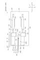
図1~図6を参照して、本発明の一実施形態に係る基板処理装置100を説明する。基板処理装置100は基板Wを処理する。基板Wは、例えば、半導体ウエハ、液晶表示装置用基板、プラズマディスプレイ用基板、電界放出ディスプレイ(Field Emission Display:FED)用基板、光ディスク用基板、磁気ディスク用基板、光磁気ディスク用基板、フォトマスク用基板、セラミック基板、又は、太陽電池用基板である。本実施形態では、基板Wは、半導体ウエハである。基板Wは、例えば、略円板状である。
A
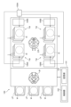
まず、図1及び図2を参照して本実施形態の基板処理装置100を説明する。図1は、本実施形態の基板処理装置100の模式図である。詳しくは、図1は、基板処理装置100の模式的な平面図である。図2は、基板処理装置100の処理ユニット1及び流体ボックス100Bを模式的に示す側面図である。基板処理装置100は、基板Wを処理する。より具体的には、基板処理装置100は、基板Wを一枚ずつ処理する枚葉式の装置である。
First, the
図1に示すように、基板処理装置100は、複数の処理ユニット1と、流体キャビネット100Aと、複数の流体ボックス100Bと、複数のロードポートLPと、インデクサロボットIRと、センタロボットCRと、制御装置101とを備える。なお、処理ユニット1は、本発明の「基板処理ユニット」の一例である。また、流体ボックス100Bは、本発明の「処理流体供給ユニット」の一例である。
As shown in FIG. 1, the
ロードポートLPの各々は、複数枚の基板Wを積層して収容する。インデクサロボットIRは、ロードポートLPとセンタロボットCRとの間で基板Wを搬送する。センタロボットCRは、インデクサロボットIRと処理ユニット1との間で基板Wを搬送する。なお、インデクサロボットIRとセンタロボットCRとの間に、基板Wを一時的に載置する載置台(パス)を設けて、インデクサロボットIRとセンタロボットCRとの間で載置台を介して間接的に基板Wを受け渡しする装置構成としてもよい。
Each load port LP accommodates multiple stacked substrates W. The indexer robot IR transports substrates W between the load port LP and the center robot CR. The center robot CR transports substrates W between the indexer robot IR and the
処理ユニット1の各々は、処理流体を基板Wの上面Wa及び下面Wb(図3参照)に供給して、基板Wの上面Wa及び下面Wbを処理する。なお、処理ユニット1の各々は、処理流体を基板Wの上面Waのみに供給して、基板Wの上面Waのみを処理してもよい。
Each of the
複数の処理ユニット1は、平面視においてセンタロボットCRを取り囲むように配置される複数のタワーTW(図1では4つのタワーTW)を形成している。各タワーTWは、上下に積層された複数の処理ユニット1(図1では3つの処理ユニット1)を含む。
The
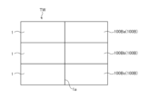
流体キャビネット100Aは、処理流体を収容する。複数の流体ボックス100Bは、それぞれ複数の処理ユニット1に対応している。具体的には、流体ボックス100Bは、上下に複数(図2では3つ)積層されている。各流体ボックス100Bは、処理ユニット1に隣接して配置される。処理ユニット1と流体ボックス100Bとの境界部分には、隔離壁1aが配置されている。隔離壁1aは、処理ユニット1内の処理流体が流体ボックス100B内に入ることを抑制する。なお、隔離壁1aは、処理ユニット1又は流体ボックス100Bに一体で設けられていてもよいし、処理ユニット1又は流体ボックス100Bとは別体で設けられていてもよい。流体キャビネット100A内の処理流体は、いずれかの流体ボックス100Bを介して、流体ボックス100Bに対応する処理ユニット1に供給される。
The
続いて、制御装置101について説明する。制御装置101は、基板処理装置100の各部の動作を制御する。例えば、制御装置101は、ロードポートLP、インデクサロボットIR、及びセンタロボットCRを制御する。また、制御装置101は、処理ユニット1及び流体ボックス100Bを制御する。制御装置101は、制御部102と、記憶部103とを含む。
Next, the
制御部102は、CPU(Central Processing Unit)のようなプロセッサを含む。制御部102のプロセッサは、記憶部103の記憶装置が記憶しているコンピュータプログラムを実行して、処理ユニット1を制御する。
The
記憶部103は、データ及びコンピュータプログラムを記憶する。データは、レシピデータを含む。レシピデータは、複数のレシピを示す情報を含む。複数のレシピの各々は、基板Wの処理内容及び処理手順を規定する。
The
記憶部103は、主記憶装置を有する。主記憶装置は、例えば、半導体メモリである。記憶部103は、補助記憶装置をさらに有してもよい。補助記憶装置は、例えば、半導体メモリ及びハードディスクドライブの少なくとも一方を含む。記憶部103はリムーバブルメディアを含んでいてもよい。制御部102は、記憶部103に記憶されているコンピュータプログラム及びデータに基づいて、基板処理装置100の各部の動作を制御する。
The
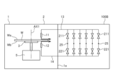
次に、図3を参照して、本実施形態の基板処理装置100の処理ユニット1及び流体ボックス100Bについてさらに説明する。図3は、本実施形態の基板処理装置100の処理ユニット1及び流体ボックス100Bの構造を示す模式図である。
Next, the
図3に示すように、処理ユニット1は、チャンバ2と、スピンチャック3と、スピンモータ部5と、第1ノズル11と、第2ノズル12とを備える。また、基板処理装置100は、第1供給配管13と、第2供給配管14とを備える。制御装置101(制御部102)は、スピンチャック3及びスピンモータ部5を制御する。なお、第1供給配管13及び第2供給配管14は、本発明の「配管」の一例である。
As shown in FIG. 3, the
チャンバ2は略箱形状を有する。チャンバ2は、基板W、スピンチャック3、スピンモータ部5、第1ノズル11、第2ノズル12、第1供給配管13の一部、及び、第2供給配管14の一部を収容する。
The
スピンチャック3は、基板Wを水平に保持する。スピンチャック3による基板Wの保持方法は、特に限定されるものではなく、例えば、基板Wの下面Wbを吸着してもよいし、基板Wの周縁部を支持してもよい。
The
スピンモータ部5は、回転軸線AX1を中心として基板Wとスピンチャック3とを一体に回転させる。回転軸線AX1は、上下方向に延びる。
The
第1ノズル11は、基板Wに処理流体を供給する。処理流体は、例えば、処理液又は処理ガスである。処理流体は、基板Wに接触する流体である限りは、特に限定されない。処理流体としての処理液は、例えば、薬液又はリンス液である。
The
薬液は、例えば、希フッ酸(DHF)、フッ酸(HF)、フッ硝酸(フッ酸と硝酸(HNO3)との混合液)、バファードフッ酸(BHF)、フッ化アンモニウム、HFEG(フッ酸とエチレングリコールとの混合液)、燐酸(H3PO4)、硫酸、酢酸、硝酸、塩酸、アンモニア水、過酸化水素水、有機酸(例えば、クエン酸、シュウ酸)、有機アルカリ(例えば、TMAH:テトラメチルアンモニウムハイドロオキサイド)、硫酸過酸化水素水混合液(SPM)、アンモニア過酸化水素水混合液(SC1)、塩酸過酸化水素水混合液(SC2)、イソプロピルアルコール(IPA)、界面活性剤、腐食防止剤、又は、疎水化剤である。 Examples of chemical solutions include dilute hydrofluoric acid (DHF), hydrofluoric acid (HF), hydronitric acid (a mixture of hydrofluoric acid and nitric acid ( HNO3 )), buffered hydrofluoric acid (BHF), ammonium fluoride, HFEG (a mixture of hydrofluoric acid and ethylene glycol ), phosphoric acid ( H3PO4 ), sulfuric acid, acetic acid, nitric acid, hydrochloric acid, ammonia water, hydrogen peroxide, organic acids (e.g., citric acid, oxalic acid), organic alkalis (e.g., TMAH: tetramethylammonium hydroxide), sulfuric acid/hydrogen peroxide mixture (SPM), ammonia/hydrogen peroxide mixture (SC1), hydrochloric acid/hydrogen peroxide mixture (SC2), isopropyl alcohol (IPA), surfactants, corrosion inhibitors, or hydrophobizing agents.
リンス液は、例えば、脱イオン水、炭酸水、電解イオン水、水素水、オゾン水、又は、希釈濃度(例えば、10ppm~100ppm程度)の塩酸水である。 The rinse liquid is, for example, deionized water, carbonated water, electrolytic ionized water, hydrogen water, ozone water, or hydrochloric acid water with a diluted concentration (for example, about 10 ppm to 100 ppm).
また、処理流体としての処理ガスは、例えば、基板Wと反応する反応ガス、又は、不活性ガスである。反応ガスは、例えば、オゾンガス、フッ素ガス、フッ化水素を含む気体、又は、IPAを含む気体である。不活性ガスは、例えば、窒素、ヘリウム、又は、アルゴンである。 The processing gas as the processing fluid is, for example, a reactive gas that reacts with the substrate W, or an inert gas. The reactive gas is, for example, ozone gas, fluorine gas, a gas containing hydrogen fluoride, or a gas containing IPA. The inert gas is, for example, nitrogen, helium, or argon.
本実施形態では、第1ノズル11は、基板Wの上面Waに処理液を供給する。処理液は、第1供給配管13を介して第1ノズル11に供給される。第1供給配管13は、処理液が流通する管状部材である。
In this embodiment, the
第2ノズル12は、基板Wに処理流体を供給する。本実施形態では、第2ノズル12は、基板Wの下面Wbに処理液を供給する。処理液は、第2供給配管14を介して第2ノズル12に供給される。第2供給配管14は、処理液が流通する管状部材である。
The
引き続き図3を参照して、流体ボックス100Bについて説明する。流体ボックス100Bは、略箱形状又は枠形状を有する。流体ボックス100Bは、バルブ211及び221と、モータ212及び222(図4参照)とを有する。バルブ211及び221には、流体キャビネット100Aから分岐部25を介して処理流体が供給される。
Continuing to refer to FIG. 3, the
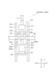
次に、図4から図6を参照して、流体ボックス100Bの詳細構造について説明する。図4は、本実施形態の基板処理装置100の流体ボックス100Bの構造を概略的に示す斜視図である。図5は、本実施形態の基板処理装置100の処理流体供給部200及び冷却用ガス供給部300の構造を示す側面図である。図6は、本実施形態の基板処理装置100の処理流体供給部200及び冷却用ガス供給部300の構造を示す正面図である。
Next, the detailed structure of the
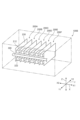
図4に示すように、流体ボックス100Bは、処理ユニット1に処理流体を供給する処理流体供給部200を有する。処理流体供給部200の数は、特に限定されるものではないが、本実施形態では、処理流体供給部200として、6つの処理流体供給部200A~200Fが設けられる。各処理流体供給部200A~200Fは、流体キャビネット100A(図1参照)に接続されており、流体キャビネット100Aから処理流体が供給される。また、各処理流体供給部200A~200Fは、第1供給配管13及び第2供給配管14(図3参照)に接続される。各処理流体供給部200A~200Fは、第1ノズル11及び第2ノズル12(図3参照)に処理流体を所定のタイミングで所定時間供給する。
As shown in FIG. 4, the
処理流体供給部200A~200Fは、互いに積層される。本実施形態では、処理流体供給部200A~200Fは、水平方向(ここではX方向)に積層される。処理流体供給部200A~200Fの各々には、上述した処理流体のうちの1つが供給される。本実施形態では、処理流体供給部200A~200Fの少なくとも1つには、高温の処理流体が供給される。また、処理流体供給部200A~200Fの少なくとも1つには、常温の処理流体が供給される。
The processing
図5及び図6に示すように、各処理流体供給部200A~200Fは、第1供給部210及び第2供給部220を有する。なお、各処理流体供給部200A~200Fは、第1供給部210及び第2供給部220のうちの一方のみを有してもよい。第1供給部210は、第1ノズル11に処理流体を供給する。第2供給部220は、第2ノズル12に処理流体を供給する。
As shown in Figures 5 and 6, each of the processing
第1供給部210は、バルブ211と、モータ(第1モータ)212と、流量計213と、接続配管214とを有する。バルブ211は、第1供給配管13に接続される。バルブ211は、処理流体の通過経路を開閉する。なお、接続配管214及び第1供給配管13等によって、処理流体が通過する通過経路が構成されている。バルブ211の種類は、特に限定されるものではないが、例えばニードルバルブである。モータ212は、バルブ211を駆動する。
The
流量計213は、流体キャビネット100Aに接続される。流量計213は、流通経路を通過する処理流体の量を計測する。接続配管214は、流量計213とバルブ211とを接続する。第1供給部210では、モータ212がバルブ211を駆動して、通過経路の開度を調整することによって、第1ノズル11に供給される処理流体の量が調整される。より具体的には、制御部102は、流量計213の計測結果に基づいてモータ212を駆動することによって、第1ノズル11に供給する処理流体の量を調整する。
The
第2供給部220は、バルブ221と、モータ(第2モータ)222と、流量計223と、接続配管224とを有する。バルブ221は、第2供給配管14に接続される。バルブ221は、処理流体の通過経路を開閉する。なお、接続配管224及び第2供給配管14等によって、処理流体が通過する通過経路が構成されている。バルブ221の種類は、特に限定されるものではないが、例えばニードルバルブである。モータ222は、バルブ221を駆動する。
The
流量計223は、流体キャビネット100Aに接続される。流量計223は、流通経路を通過する処理流体の量を計測する。接続配管224は、流量計223とバルブ221とを接続する。第2供給部220では、モータ222がバルブ221を駆動して、通過経路の開度を調整することによって、第2ノズル12に供給される処理流体の量が調整される。より具体的には、制御部102は、流量計223の計測結果に基づいてモータ222を駆動することによって、第2ノズル12に供給する処理流体の量を調整する。
The
ここで、基板Wの処理を続けると、モータ212及び222が駆動し続ける。このため、モータ212及び222が高温になる。モータ212及び222の熱は、バルブ211及び221を介して処理流体に伝達されるため、処理流体の温度が上昇する。よって、温度の上昇した処理流体が基板Wに供給されるため、基板Wに対する処理速度及び処理量が増加してしまう。
If the processing of the substrate W continues, the
そこで、本実施形態では、基板処理装置100は、モータ212及び222の温度が上昇するのを抑制するための冷却用ガス供給部300を備える。冷却用ガス供給部300は、冷却用ガスがモータ212の側面(ここでは下面)212a及びモータ222の側面(ここでは上面)222aを通過するように、冷却用ガスを吹き出す。従って、冷却用ガスによってモータ212及び222の温度が高温になることを抑制できる。よって、モータ212及び222の熱が処理流体に伝達されることを抑制できるので、処理流体の温度が上昇することを抑制できる。その結果、温度の上昇した処理流体が基板Wに供給されることを抑制できるため、基板Wの処理速度及び処理量が増加することを抑制できる。このように、本実施形態では、基板処理装置100が冷却用ガス供給部300を備えることによって、モータ212及び222の発熱によって処理流体が高温になることを抑制できる。
Therefore, in this embodiment, the
また、例えば、処理流体供給部200A~200Fの1つがアンモニア水を供給し、処理流体供給部200A~200Fの他の1つが過酸化水素水を供給して、アンモニア過酸化水素水混合液(SC1)を基板Wに吐出する場合、過酸化水素水に対して少量のアンモニア水を混ぜることになる。この場合、アンモニア水の温度が上昇し、アンモニア水の体積が変化すると、アンモニアの希釈度が大きく変化する。つまり、処理流体を希釈して用いる場合、温度変化の影響が大きくなるため、処理流体の温度変化を抑制することは、特に有効である。
For example, when one of the processing
なお、本実施形態では、冷却用ガス供給部300は、処理流体によって基板Wを処理している際は常時、冷却用ガスを吹き出すが、例えば、モータ212及び222の温度を計測し、モータ212及び222が所定温度以上になった場合のみ冷却用ガスを吹き出してもよい。
In this embodiment, the cooling
本実施形態では、冷却用ガス供給部300は、処理流体供給部200A~200Fの積層方向(X方向)に延びる管部材である。なお、処理流体供給部200A~200Fの積層方向は、本発明の「所定方向」の一例である。冷却用ガス供給部300は、冷却用ガスを吹き出す吹出口300aを有する。吹出口300aは、単数個であっても良いし、複数個あっても良い。以下、吹出口300aが複数ある実施態様について説明する。
In this embodiment, the cooling
複数の吹出口300aは、処理流体供給部200の積層方向(X方向)に、互いに離隔する。冷却用ガス供給部300には、流体キャビネット100Aから冷却用ガスが供給される。流体キャビネット100Aから冷却用ガス供給部300に供給された冷却用ガスは、複数の吹出口300aから吹き出される。このように、冷却用ガス供給部300は、複数の吹出口300aを有し、複数の吹出口300aは、積層方向(所定方向)に互いに離隔することによって、1つの冷却用ガス供給部300によって、複数のモータ212及び222が高温になることを抑制できる。
The
冷却用ガスの種類は、特に限定されるものではないが、例えば、空気、又は、窒素等の不活性ガスを用いることができる。また、冷却用ガスの温度は、特に限定されるものではないが、例えば常温である。 The type of cooling gas is not particularly limited, but may be, for example, air or an inert gas such as nitrogen. The temperature of the cooling gas is not particularly limited, but may be, for example, room temperature.
各処理流体供給部200A~200Fは、支持部材230をさらに有する。支持部材230は、バルブ211及び221と、モータ212及び222とを支持する。本実施形態では、支持部材230は、仕切り板である。具体的には、複数のバルブ211及び複数のモータ212は、水平方向に所定間隔をおいて複数(ここでは6個)ずつ配置される。複数のバルブ221及び複数のモータ222は、水平方向に所定間隔をおいて複数(ここでは6個)ずつ配置される。複数のバルブ211及び複数のモータ212と、複数のバルブ221及び複数のモータ222とは、上下方向に所定間隔をおいて配置される。そして、支持部材230は、水平方向(X方向)に隣接するバルブ211同士、モータ212同士、バルブ221同士、モータ222同士を仕切る。言い換えると、複数のモータ212及び222は、上下方向に互いに離隔する一対のモータ212及び222を複数組(ここでは6組)含む。複数のバルブ211及び221は、上下方向に互いに離隔する一対のバルブ211及び221を複数組(ここでは6組)含む。
Each of the processing
複数の支持部材230は、所定方向(X方向)に互いに離隔する。支持部材230は、板本体231と、2つの第1支持板部232と、2つの第2支持板部233とを有する。2つの第1支持板部232は、板本体231から水平方向に突出する。本実施形態では、2つの第1支持板部232は、板本体231から、処理ユニット1とは反対側(X方向の一方側X1)に突出する。2つの第1支持板部232は、上下方向に互いに離隔し、バルブ211及び221をそれぞれ支持する。2つの第2支持板部233は、板本体231から水平方向に突出する。本実施形態では、2つの第2支持板部233は、板本体231から、処理ユニット1とは反対側(X方向の一方側X1)に突出する。2つの第2支持板部233は、上下方向に互いに離隔し、流量計213及び223をそれぞれ支持する。2つの第2支持板部233は、2つの第1支持板部232に対して、処理流体供給部200の積層方向(X方向)に対して交差する方向(Y方向)に配置される。
The
第1供給配管13は、バルブ211に接続する接続部13aと、接続部13aから正面側(Y方向の一方側Y1)に延びる第1部分13bと、第1部分13bから上方に延びる第2部分13cとを有する。第2供給配管14は、バルブ221に接続する接続部14aと、接続部14aから正面側(Y方向の一方側Y1)に延びる第1部分14bと、第1部分14bから上方に延びる第2部分14cとを有する。
The
上述したように、支持部材230は、モータ212同士、モータ222同士を仕切る仕切り板である。従って、支持部材230に挟まれた空間の空気は、処理流体供給部200A~200Fの積層方向(X方向)に流通しにくい。よって、支持部材230に挟まれた空間には、熱が籠りやすい。このため、支持部材230が仕切り板である場合に、本発明を適用してモータ212及び222の温度が高温になることを抑制することは、特に有効である。また、本実施形態では、隣接する支持部材230、モータ212及び222によって、空間S200が形成される。空間S200は、上方にモータ212が配置されるため、熱が籠りやすい。
As described above, the
本実施形態では、冷却用ガス供給部300は、支持部材230に沿うように冷却用ガスを吹き出す。従って、空間S200の空気が支持部材230に沿って背面側(Y方向の他方側Y2)に流れるため、空間S200に熱が籠ることを抑制できる。よって、モータ212及び222が高温になることを効果的に抑制できる。具体的には、複数の吹出口300aは、冷却用ガス供給部300のうち背面側(Y方向の他方側Y2)の部分に形成される。
In this embodiment, the cooling
また、本実施形態では、冷却用ガス供給部300は、一対のモータ212及び222の間を通過するように冷却用ガスを吹き出す。従って、一対のモータ212及び222の間に籠る熱を効果的に背面側に導くことができる。よって、モータ212及び222が高温になることをより効果的に抑制できる。具体的には、冷却用ガス供給部300は、正面側(Y方向の一方側Y1)から見て一対のモータ212及び222の間に配置される。
In addition, in this embodiment, the cooling
また、本実施形態では、冷却用ガス供給部300は、第1供給配管13及び第2供給配管14を避けつつ、モータ212の側面212a及びモータ222の側面222aを通過するように冷却用ガスを吹き出す。従って、第1供給配管13及び第2供給配管14の内部を通過する処理流体の温度が低下しすぎることを抑制できる。具体的には、図6に示すように、正面側から見て、吹出口300aは、第1供給配管13及び第2供給配管14に重なっていない。本実施形態では、正面側から見て、吹出口300aは、第2供給配管14と支持部材230との間に配置される。
In addition, in this embodiment, the cooling
また、図5に示すように、冷却用ガス供給部300は、背面側の少しだけ下方向に向かって冷却用ガスを吹き出す。本実施形態では、冷却用ガス供給部300は、バルブ211とバルブ221との隙間の、上下方向の中心部C200に向かって冷却用ガスを吹き出す。よって、モータ212とモータ222との間の空気を、効率良くバルブ211とバルブ221との間を通過させることができる。
As shown in FIG. 5, the cooling
また、本実施形態では、図6に示すように、正面側から見て、空間S200は、第2供給配管14によって、第1空間S200aと第2空間S200bとに区分けされる。本実施形態では、1つの空間S200に対して吹出口300aが2つ配置される。2つの吹出口300aの一方は、第1空間S200aの中心部に向かって冷却用ガスを吹き出し、2つの吹出口300aの他方は、第2空間S200bの中心部に向かって冷却用ガスを吹き出す。
In addition, in this embodiment, as shown in FIG. 6, when viewed from the front side, the space S200 is divided into a first space S200a and a second space S200b by the
冷却用ガス供給部300は、上下に積層された複数の流体ボックス100Bのうち、少なくとも最上段の流体ボックス100Ba(図2参照)内に配置される。本実施形態では、複数の流体ボックス100Bは、内部の空気が互いに通過可能な状態で上下方向に積層される。このため、最下段の流体ボックス100Bc(図2参照)の熱、及び、1つ以上(ここでは1つ)の中段の流体ボックス100Bb(図2参照)の熱は、最上段の流体ボックス100Baに溜まりやすい。よって、最上段の流体ボックス100Baのモータ212及び222が高温になりやすい。本実施形態では、上述したように、冷却用ガス供給部300が少なくとも最上段の流体ボックス100Ba内に配置されることによって、高温になりやすい最上段の流体ボックス100Baのモータ212及び222が高温になることを抑制できる。従って、複数の流体ボックス100B間でモータ212及び222の温度がばらつくことを抑制できる。よって、複数の流体ボックス100B間で処理流体の温度がばらつくことを抑制できる。その結果、複数の処理ユニット1間で基板Wに対する処理速度及び処理量がばらつくことを抑制できる。
The cooling
また、本実施形態では、冷却用ガス供給部300は、少なくとも最下段の流体ボックス100Bc内には配置されない。従って、少なくとも最下段の流体ボックス100Bcのモータ212及び222の温度が低くなりすぎることを抑制できる。よって、複数の流体ボックス100B間で処理流体の温度がばらつくことをより抑制できる。
In addition, in this embodiment, the cooling
また、流体ボックス100B内は、負圧に保持される。これにより、処理流体の揮発成分等が流体ボックス100Bから外部に漏れることを抑制できる。具体的には、流体ボックス100Bには、吸引装置(図示せず)が接続されており、1分当たり数100リットル以上の空気が排気される。冷却用ガス供給部300は、吸引装置による排気量(数100リットル/分以上)よりも少ない量の冷却用ガスを流体ボックス100B内に吹き出す。従って、流体ボックス100B内が正圧になることを抑制できる。なお、冷却用ガス供給部300が冷却用ガスを吹き出す量は、吸引装置による排気量の10分の1以下であることが好ましい。
Furthermore, the inside of the
以上、図面を参照して本発明の実施形態について説明した。ただし、本発明は、上記の実施形態に限られるものではなく、その要旨を逸脱しない範囲で種々の態様において実施できる。また、上記の実施形態に開示される複数の構成要素は適宜改変可能である。例えば、ある実施形態に示される全構成要素のうちのある構成要素を別の実施形態の構成要素に追加してもよく、又は、ある実施形態に示される全構成要素のうちのいくつかの構成要素を実施形態から削除してもよい。 The above describes the embodiments of the present invention with reference to the drawings. However, the present invention is not limited to the above embodiments, and can be implemented in various aspects without departing from the gist of the present invention. In addition, the components disclosed in the above embodiments can be modified as appropriate. For example, a component among all the components shown in one embodiment may be added to a component of another embodiment, or some of all the components shown in one embodiment may be deleted from the embodiment.
また、図面は、発明の理解を容易にするために、それぞれの構成要素を主体に模式的に示しており、図示された各構成要素の厚さ、長さ、個数、間隔等は、図面作成の都合上から実際とは異なる場合もある。また、上記の実施形態で示す各構成要素の構成は一例であって、特に限定されるものではなく、本発明の効果から実質的に逸脱しない範囲で種々の変更が可能であることは言うまでもない。 In addition, the drawings mainly show each component in a schematic manner in order to facilitate understanding of the invention, and the thickness, length, number, spacing, etc. of each component shown in the drawings may differ from the actual ones due to the convenience of creating the drawings. Furthermore, the configuration of each component shown in the above embodiment is one example and is not particularly limited, and it goes without saying that various modifications are possible within a range that does not substantially deviate from the effects of the present invention.
例えば、上記の実施形態では、各流体ボックス100Bが複数のバルブ211及び221と、複数のモータ212及び222とを有する例について示したが、本発明はこれに限らない。例えば、各流体ボックス100Bが1つのバルブ211又は221と、1つのモータ212又は222とを有してもよい。
For example, in the above embodiment, an example is shown in which each
また、上記の実施形態では、流体ボックス100Bが上下に3段積層される例について示したが、本発明はこれに限らない。例えば、流体ボックス100Bは上下に積層されなくてもよい。また、例えば、流体ボックス100Bは、上下に2つだけ積層されてもよいし、上下に4つ以上積層されてもよい。
In addition, in the above embodiment, an example in which the
また、上記の実施形態では、冷却用ガス供給部300が少なくとも最下段の流体ボックス100Bc内には配置されない例について示したが、本発明はこれに限らない。例えば、冷却用ガス供給部300は、全ての流体ボックス100Bc内に配置されてもよい。
In addition, in the above embodiment, an example was shown in which the cooling
また、上記の実施形態では、支持部材230が仕切り板である例について示したが、本発明はこれに限らない。例えば、支持部材230は、板状でなくてもよい。
In addition, in the above embodiment, an example was shown in which the
また、上記の実施形態では、複数の処理流体供給部200が積層される例について示したが、本発明はこれに限らない。例えば、1つの流体ボックス100Bに対して、1つの処理流体供給部200のみが設けられてもよい。
In addition, in the above embodiment, an example in which multiple processing
また、上記の実施形態では、複数の処理流体供給部200が水平方向に積層される例について示したが、本発明はこれに限らない。例えば、複数の処理流体供給部200が上下方向に積層されてもよい。この場合、冷却用ガス供給部300は、上下方向に延びるように配置されてもよい。
In addition, in the above embodiment, an example in which multiple processing
また、上記の実施形態では、1つの流体ボックス100B内に1つの冷却用ガス供給部300が配置される例について示したが、本発明はこれに限らない。例えば、1つの流体ボックス100B内に2つ以上の冷却用ガス供給部300を配置してもよい。
In addition, in the above embodiment, an example in which one cooling
また、上記の実施形態では、冷却用ガス供給部300が一対のモータ212及び222の間を通過するように冷却用ガスを吹き出す例について示したが、本発明はこれに限らない。例えば、冷却用ガス供給部300がモータ212又は222に向かって冷却用ガスを吹き出してもよい。
In the above embodiment, the cooling
本発明は、基板処理装置に関するものであり、産業上の利用可能性を有する。 The present invention relates to a substrate processing apparatus and has industrial applicability.
1 :処理ユニット(基板処理ユニット)
13 :第1供給配管(配管)
14 :第2供給配管(配管)
100 :基板処理装置
100B、100Ba、100Bb、100Bc :流体ボックス(処理流体供給ユニット)
211、221 :バルブ
212、222 :モータ
212a、222a :側面
230 :支持部材
300 :冷却用ガス供給部
W :基板
1: Processing unit (substrate processing unit)
13: First supply pipe (piping)
14: Second supply pipe (piping)
100:
211, 221:
Claims (4)
前記基板処理ユニットに前記処理流体を供給する処理流体供給ユニットと、
前記処理流体供給ユニット内に配置される冷却用ガス供給部と
を備え、
前記処理流体供給ユニットは、前記処理流体の通過経路を開閉する複数のバルブと、前記バルブをそれぞれ駆動する複数のモータと、隣り合う前記モータを仕切る複数の仕切り板であって、所定方向に互いに離隔し、前記所定方向に交差する方向に沿う仕切り板とを有し、隣り合う前記仕切り板が、前記モータを挟んで前記所定方向に対向しており、
前記冷却用ガス供給部は、前記所定方向に互いに離隔した複数の吹出口を有し、
前記複数の吹出口は、それぞれ、複数の前記モータの側面を通過するようにかつ複数の前記仕切り板に沿うように冷却用ガスを吹き出す、基板処理装置。 a substrate processing unit that supplies a processing fluid to a substrate to process the substrate;
a processing fluid supply unit for supplying the processing fluid to the substrate processing unit;
a cooling gas supply unit disposed in the processing fluid supply unit,
the treatment fluid supply unit includes a plurality of valves for opening and closing a passageway for the treatment fluid, a plurality of motors for driving the valves , and a plurality of partition plates for separating adjacent motors, the partition plates being spaced apart from each other in a predetermined direction and extending along a direction intersecting the predetermined direction, the adjacent partition plates facing each other in the predetermined direction with the motors therebetween;
The cooling gas supply unit has a plurality of outlets spaced apart from each other in the predetermined direction,
The substrate processing apparatus, wherein the plurality of blowing ports blow out the cooling gas so as to pass through side surfaces of the plurality of motors and along the plurality of partition plates, respectively .
前記冷却用ガス供給部は、前記第1モータおよび前記第2モータの間を通過するように冷却用ガスを吹き出す、請求項1に記載の基板処理装置。 The motor includes a first motor and a second motor spaced apart from each other in a vertical direction,
The substrate processing apparatus according to claim 1 , wherein the cooling gas supply unit blows out the cooling gas so that the cooling gas passes between the first motor and the second motor .
前記冷却用ガス供給部は、前記配管を避けつつ、前記モータの側面を通過するように冷却用ガスを吹き出す、請求項1または請求項2に記載の基板処理装置。 Further comprising a pipe through which the processing fluid passes,
3 . The substrate processing apparatus according to claim 1 , wherein the cooling gas supply unit blows out the cooling gas so as to pass a side surface of the motor while avoiding the piping.
各前記処理流体供給ユニットは、複数の前記バルブおよび複数の前記モータを収容する筐体をさらに有し、
前記複数の処理流体供給ユニットは、前記筐体の内部の空気が互いに通過可能な状態で上下方向に積層され、
前記冷却用ガス供給部は、少なくとも最上段の前記処理流体供給ユニット内に配置され、
前記冷却用ガス供給部は、最下段の前記処理流体供給ユニット内には配置されない、請求項1から請求項3のいずれか1項に記載の基板処理装置。 A plurality of the processing fluid supply units are provided,
Each of the processing fluid supply units further includes a housing that houses a plurality of the valves and a plurality of the motors;
the plurality of treatment fluid supply units are stacked vertically in a state in which air inside the housing can pass through each other,
the cooling gas supply unit is disposed in at least the uppermost processing fluid supply unit ,
The substrate processing apparatus according to claim 1 , wherein the cooling gas supply unit is not disposed in a lowermost processing fluid supply unit .
Priority Applications (1)
| Application Number | Priority Date | Filing Date | Title |
|---|---|---|---|
| JP2021155513A JP7671663B2 (en) | 2021-09-24 | 2021-09-24 | Substrate Processing Equipment |
Applications Claiming Priority (1)
| Application Number | Priority Date | Filing Date | Title |
|---|---|---|---|
| JP2021155513A JP7671663B2 (en) | 2021-09-24 | 2021-09-24 | Substrate Processing Equipment |
Publications (2)
| Publication Number | Publication Date |
|---|---|
| JP2023046743A JP2023046743A (en) | 2023-04-05 |
| JP7671663B2 true JP7671663B2 (en) | 2025-05-02 |
Family
ID=85778406
Family Applications (1)
| Application Number | Title | Priority Date | Filing Date |
|---|---|---|---|
| JP2021155513A Active JP7671663B2 (en) | 2021-09-24 | 2021-09-24 | Substrate Processing Equipment |
Country Status (1)
| Country | Link |
|---|---|
| JP (1) | JP7671663B2 (en) |
Citations (5)
| Publication number | Priority date | Publication date | Assignee | Title |
|---|---|---|---|---|
| JP2006035185A (en) | 2004-07-30 | 2006-02-09 | Tokyo Electron Ltd | Treatment liquid supply method and treatment liquid supply apparatus |
| JP2011035135A (en) | 2009-07-31 | 2011-02-17 | Tokyo Electron Ltd | Liquid processing apparatus, liquid processing method, program, and program storage medium |
| US20140261805A1 (en) | 2013-03-15 | 2014-09-18 | Applied Materials, Inc. | Gas distribution apparatus for directional and proportional delivery of process gas to a process chamber |
| JP2016111306A (en) | 2014-12-10 | 2016-06-20 | 株式会社Screenホールディングス | Suck-back valve, suck-back valve system and substrate processing apparatus |
| JP2020155620A (en) | 2019-03-20 | 2020-09-24 | 株式会社Screenホールディングス | Control method of treatment liquid supply device and treatment liquid supply device |
Family Cites Families (9)
| Publication number | Priority date | Publication date | Assignee | Title |
|---|---|---|---|---|
| JPS61214520A (en) * | 1985-03-20 | 1986-09-24 | Hitachi Ltd | Coating device |
| EP0498006A1 (en) * | 1991-02-06 | 1992-08-12 | International Business Machines Corporation | Superheterodyning technique in the spatial frequency domain and structure for pattern registration measurement |
| JP3412704B2 (en) * | 1993-02-26 | 2003-06-03 | 株式会社ニコン | Projection exposure method and apparatus, and exposure apparatus |
| JP4222927B2 (en) * | 2002-09-20 | 2009-02-12 | エーエスエムエル ネザーランズ ビー.ブイ. | Lithographic apparatus alignment system using at least two wavelengths |
| KR100914745B1 (en) * | 2007-11-13 | 2009-08-31 | 세메스 주식회사 | Valve and apparatus for treating substrate with the valve |
| EP2458441B1 (en) * | 2010-11-30 | 2022-01-19 | ASML Netherlands BV | Measuring method, apparatus and substrate |
| CN104111594B (en) * | 2013-04-16 | 2016-09-28 | 上海微电子装备有限公司 | Two-dimentional self-reference based on signal frequency is interfered Barebone and alignment methods |
| CN109643071B (en) * | 2016-08-15 | 2021-04-23 | Asml荷兰有限公司 | Alignment method |
| JP7060695B2 (en) * | 2018-01-17 | 2022-04-26 | エーエスエムエル ネザーランズ ビー.ブイ. | Feature diagnosis of scan signal |
-
2021
- 2021-09-24 JP JP2021155513A patent/JP7671663B2/en active Active
Patent Citations (5)
| Publication number | Priority date | Publication date | Assignee | Title |
|---|---|---|---|---|
| JP2006035185A (en) | 2004-07-30 | 2006-02-09 | Tokyo Electron Ltd | Treatment liquid supply method and treatment liquid supply apparatus |
| JP2011035135A (en) | 2009-07-31 | 2011-02-17 | Tokyo Electron Ltd | Liquid processing apparatus, liquid processing method, program, and program storage medium |
| US20140261805A1 (en) | 2013-03-15 | 2014-09-18 | Applied Materials, Inc. | Gas distribution apparatus for directional and proportional delivery of process gas to a process chamber |
| JP2016111306A (en) | 2014-12-10 | 2016-06-20 | 株式会社Screenホールディングス | Suck-back valve, suck-back valve system and substrate processing apparatus |
| JP2020155620A (en) | 2019-03-20 | 2020-09-24 | 株式会社Screenホールディングス | Control method of treatment liquid supply device and treatment liquid supply device |
Also Published As
| Publication number | Publication date |
|---|---|
| JP2023046743A (en) | 2023-04-05 |
Similar Documents
| Publication | Publication Date | Title |
|---|---|---|
| US5988189A (en) | Method and apparatus for cleaning wafers using multiple tanks | |
| WO2019171670A1 (en) | Substrate treatment method and substrate treatment device | |
| TWI797826B (en) | Processing liquid circulation method and substrate processing method | |
| JP2009117824A (en) | Substrate processing apparatus and manufacturing method thereof | |
| JP7585124B2 (en) | Treatment liquid flow method and treatment liquid supply device | |
| US12142474B2 (en) | Substrate processing method and substrate processing system | |
| JP2009267167A (en) | Substrate-treating device | |
| JP7546749B2 (en) | SUBSTRATE PROCESSING METHOD AND SUBSTRATE PROCESSING APPARATUS | |
| JP7671663B2 (en) | Substrate Processing Equipment | |
| JP2010118498A (en) | Method for processing substrate and substrate processing equipment | |
| US20080163900A1 (en) | Ipa delivery system for drying | |
| JP2020088085A (en) | Substrate processing method and substrate processing apparatus | |
| TW202217947A (en) | Substrate processing apparatus and substrate processing method | |
| JP7203579B2 (en) | Substrate processing equipment | |
| JP7672841B2 (en) | Substrate processing apparatus and substrate processing method | |
| JP2008251657A (en) | Substrate treatment device | |
| JP6803737B2 (en) | Substrate processing method and substrate processing equipment | |
| TWI915282B (en) | Substrate processing system | |
| US11998954B2 (en) | Substrate processing apparatus and substrate processing method | |
| KR102620707B1 (en) | Liquid membrane forming apparatus, and liquid processing apparatus and substrate processing equipment including the same | |
| JP7843192B2 (en) | Substrate processing equipment | |
| US20250279293A1 (en) | Substrate processing apparatus and substrate processing method | |
| JP7853815B2 (en) | Method for supplying inert gas and substrate processing apparatus | |
| KR102134431B1 (en) | Substrate treating apparatus | |
| KR20150043893A (en) | Chemical liquid supply method |
Legal Events
| Date | Code | Title | Description |
|---|---|---|---|
| A621 | Written request for application examination |
Free format text: JAPANESE INTERMEDIATE CODE: A621 Effective date: 20240617 |
|
| RD02 | Notification of acceptance of power of attorney |
Free format text: JAPANESE INTERMEDIATE CODE: A7422 Effective date: 20240625 |
|
| A977 | Report on retrieval |
Free format text: JAPANESE INTERMEDIATE CODE: A971007 Effective date: 20241225 |
|
| A131 | Notification of reasons for refusal |
Free format text: JAPANESE INTERMEDIATE CODE: A131 Effective date: 20250109 |
|
| A521 | Request for written amendment filed |
Free format text: JAPANESE INTERMEDIATE CODE: A523 Effective date: 20250214 |
|
| TRDD | Decision of grant or rejection written | ||
| A01 | Written decision to grant a patent or to grant a registration (utility model) |
Free format text: JAPANESE INTERMEDIATE CODE: A01 Effective date: 20250410 |
|
| A61 | First payment of annual fees (during grant procedure) |
Free format text: JAPANESE INTERMEDIATE CODE: A61 Effective date: 20250421 |
|
| R150 | Certificate of patent or registration of utility model |
Ref document number: 7671663 Country of ref document: JP Free format text: JAPANESE INTERMEDIATE CODE: R150 |