JP7608830B2 - Authentication Devices and Films - Google Patents
Authentication Devices and Films Download PDFInfo
- Publication number
- JP7608830B2 JP7608830B2 JP2020534999A JP2020534999A JP7608830B2 JP 7608830 B2 JP7608830 B2 JP 7608830B2 JP 2020534999 A JP2020534999 A JP 2020534999A JP 2020534999 A JP2020534999 A JP 2020534999A JP 7608830 B2 JP7608830 B2 JP 7608830B2
- Authority
- JP
- Japan
- Prior art keywords
- film
- authentication device
- light
- light source
- wavelength
- Prior art date
- Legal status (The legal status is an assumption and is not a legal conclusion. Google has not performed a legal analysis and makes no representation as to the accuracy of the status listed.)
- Active
Links
Images


Classifications
-
- G—PHYSICS
- G02—OPTICS
- G02B—OPTICAL ELEMENTS, SYSTEMS OR APPARATUS
- G02B5/00—Optical elements other than lenses
- G02B5/30—Polarising elements
- G02B5/3025—Polarisers, i.e. arrangements capable of producing a definite output polarisation state from an unpolarised input state
- G02B5/3033—Polarisers, i.e. arrangements capable of producing a definite output polarisation state from an unpolarised input state in the form of a thin sheet or foil, e.g. Polaroid
-
- G—PHYSICS
- G02—OPTICS
- G02B—OPTICAL ELEMENTS, SYSTEMS OR APPARATUS
- G02B1/00—Optical elements characterised by the material of which they are made; Optical coatings for optical elements
- G02B1/04—Optical elements characterised by the material of which they are made; Optical coatings for optical elements made of organic materials, e.g. plastics
-
- G—PHYSICS
- G02—OPTICS
- G02B—OPTICAL ELEMENTS, SYSTEMS OR APPARATUS
- G02B5/00—Optical elements other than lenses
- G02B5/30—Polarising elements
-
- G—PHYSICS
- G06—COMPUTING OR CALCULATING; COUNTING
- G06T—IMAGE DATA PROCESSING OR GENERATION, IN GENERAL
- G06T1/00—General purpose image data processing
Landscapes
- Physics & Mathematics (AREA)
- General Physics & Mathematics (AREA)
- Optics & Photonics (AREA)
- Engineering & Computer Science (AREA)
- Theoretical Computer Science (AREA)
- Polarising Elements (AREA)
- Arrangement Of Elements, Cooling, Sealing, Or The Like Of Lighting Devices (AREA)
- Electroluminescent Light Sources (AREA)
- Planar Illumination Modules (AREA)
- Materials For Medical Uses (AREA)
- Separation Using Semi-Permeable Membranes (AREA)
Description
本発明は、光源、偏光子、フィルム、光感度センサーを有する認証デバイスに関するものである。 The present invention relates to an authentication device having a light source, a polarizer, a film and a light sensitivity sensor.
近年の画像処理技術およびデータ解析技術の発展に伴い、多様な認証システムが実用化されている。特に指紋認証、虹彩認証、静脈認証、顔認証などの生体認証デバイスは、精度の向上と低コスト化が進み、携帯電話や車両など様々な電子製品において使用され始めている。今後さらに車両や電子決済などで使用されていくと予想されることから、更なる精度や低コスト化、また長期で使用する場合の耐久性を持った認証デバイスが求められている。 With the recent development of image processing and data analysis technologies, a variety of authentication systems have been put into practical use. In particular, biometric authentication devices such as fingerprint, iris, vein, and face authentication have become more accurate and less expensive, and are beginning to be used in a variety of electronic products such as mobile phones and vehicles. As their use is expected to increase in vehicles and electronic payments in the future, there is a demand for authentication devices that are even more accurate, less expensive, and durable enough for long-term use.
特許文献1に示されているように、一般に光学式の認証デバイスは光源から発した光を認証対象物に照射し、反射した光を光感度センサーで受光、撮像し、パターン化した画像をあらかじめ登録されているパターンとマッチングすることで認証を行う。そのような認証デバイスでは、光源から発した以外の光が入射してしまうと誤認証の原因となるため、偏光子を用いて外光の反射を抑えている場合が多い。また、最表層にはポリエステルやポリカーボネートなど熱可塑性樹脂のフィルムを用いることで、破損やキズによる認証機能低下を防いでいる。As shown in
しかしながら、前記フィルムに偏光性や旋光性がある場合、光源からの光が偏光/旋光されてしまう結果、偏光/旋光された光は光感度センサーに届くまでに偏光子によって遮断されるため、認証性が低下するという問題が発生する。However, if the film has polarizing or optically rotatory properties, the light from the light source is polarized/rotated, and the polarized/rotated light is blocked by the polarizer before it reaches the light sensitivity sensor, resulting in a problem of reduced authenticity.
かかる問題に対しては二通りの対策が考えられる。一つ目は光学的にほぼ等方なポリカーボネートなどの未延伸、もしくは微延伸フィルムを保護フィルムとする方法がある。しかしながら、延伸倍率の低いフィルムは割れやすく、耐衝撃性に難がある。また、耐衝撃性の高いポリカーボネートフィルムは高価であるという課題を有する。There are two possible solutions to this problem. The first is to use an unstretched or slightly stretched film of an optically nearly isotropic material such as polycarbonate as the protective film. However, films with a low stretch ratio are prone to cracking and have poor impact resistance. Another issue is that polycarbonate films, which have high impact resistance, are expensive.
二つ目は配向せしめたポリエステルフィルムを保護フィルムとして用い、配向ポリエステルフィルムの主配向軸を偏光子の透過軸と平行にすることで、保護フィルムでの偏光を実質的に無くす方法である。しかしながら、かかる方法では、主配向軸の方向と、偏光子の透過軸が、わずか数度ずれると偏光性が顕在化してしまい、認証性が低下するという課題を有する。The second method is to use an oriented polyester film as a protective film and align the main orientation axis of the oriented polyester film parallel to the transmission axis of the polarizer, thereby substantially eliminating polarization in the protective film. However, this method has the problem that if the direction of the main orientation axis and the transmission axis of the polarizer are misaligned by just a few degrees, polarization becomes apparent, reducing authentication ability.
また光源としてOLED(Organic Light Emitting Diode)を用いている認証デバイスでは、紫外線などによるOLEDの劣化が長期使用のためのネックになっており、OLEDの耐久性を向上させることが認証デバイスの耐用年数向上に直結する課題となっている。 In addition, in authentication devices that use OLEDs (organic light emitting diodes) as the light source, degradation of the OLEDs due to ultraviolet rays and other factors is an obstacle to long-term use, and improving the durability of OLEDs is an issue that is directly linked to extending the service life of authentication devices.
本発明は、上記の課題を解決せんとするものであって、フィルムの配向角に認証性が依存することのない認証デバイスを提供することを課題とする。 The present invention aims to solve the above problems and provides an authentication device whose authenticity does not depend on the orientation angle of the film.
本発明は、上記の課題を解決せんとするものである。すなわち、光源、偏光子、フィルム、光感度センサーを有する認証デバイスであって、前記のフィルムは偏光子と認証対象物の間に配置され、かつ下記(1)および(2)を満足することを特徴とする認証デバイスである。
(1)前記光源から出射する光線の透過率が、当該光線の最も強い強度の波長において70%以上100%以下であること。
(2)下記(I)式を満足する整数nが存在すること。
(I)A×n-150 ≦ Re ≦ A×n+150
ここで、Aは前記光源から出射する光線において最も強い強度を示す波長(nm)であり、Reは前記フィルムを平行ニコル回転法を用いて入射角0°での波長587.8nmで測定したときの面内位相差(nm)である。
The present invention aims to solve the above problems, that is, an authentication device having a light source, a polarizer, a film, and a light sensitivity sensor, the film being disposed between the polarizer and an object to be authenticated, and satisfying the following (1) and (2):
(1) The transmittance of the light beam emitted from the light source is 70% or more and 100% or less at the wavelength at which the light beam has the strongest intensity.
(2) There exists an integer n that satisfies the following formula (I):
(I) A×n-150 ≦ Re ≦ A×n+150
Here, A is the wavelength (nm) at which the light emitted from the light source exhibits the strongest intensity, and Re is the in-plane retardation (nm) when the film is measured at a wavelength of 587.8 nm at an incident angle of 0° using the parallel Nicol rotation method.
本発明に依れば、フィルムの配向角に認証性が依存することのない認証デバイスを提供できる。また、安価なフィルムを用いることができ、光源の耐久性および画面の耐衝撃性を向上させることができる。 According to the present invention, it is possible to provide an authentication device whose authenticity does not depend on the orientation angle of the film. In addition, it is possible to use an inexpensive film, and it is possible to improve the durability of the light source and the impact resistance of the screen.
以下、本発明の実施の形態について詳細に述べるが、本発明は以下の実施例を含む実施の形態に限定して解釈されるものではなく、発明の目的を達成できて、かつ、発明の要旨を逸脱しない範囲においての種々の変更は当然ありうる。 The following describes in detail the embodiments of the present invention, but the present invention should not be construed as being limited to the embodiments including the examples below, and various modifications are naturally possible as long as the object of the invention is achieved and the gist of the invention is not deviated from.
本発明の認証デバイスは、光源、偏光子、フィルム、光感度センサーを有する認証デバイスであって、偏光子と認証対象物の間に下記(1)および(2)を満足するフィルムが配置されている認証デバイスである。
(1)前記フィルムが、前記光源から出射する光の最も強い強度を持つ波長における透過率が70%以上100%以下であること。
(2)前記光源から出射する光線の最も強い強度を持つ波長をA(nm)、前記フィルムの平行ニコル回転法で測定される入射角0°での波長587.8nmの面内位相差をRe(nm)としたとき、下記(I´)式を満足すること。
(I´)A×n-150 ≦ Re < A×n+150
ただし、nは整数である。
The authentication device of the present invention is an authentication device having a light source, a polarizer, a film, and a light sensitivity sensor, in which a film that satisfies the following (1) and (2) is placed between the polarizer and the object to be authenticated.
(1) The film has a transmittance of 70% or more and 100% or less at the wavelength having the strongest intensity of the light emitted from the light source.
(2) When the wavelength at which the light emitted from the light source has the strongest intensity is A (nm) and the in-plane retardation of the film at a wavelength of 587.8 nm at an incident angle of 0° measured by the parallel Nicol rotation method is Re (nm), the following formula (I') is satisfied:
(I') A×n-150 ≦ Re < A×n+150
Here, n is an integer.
より詳細には、本発明の認証デバイスは、光源、偏光子、フィルム、および光感度センサーを有する認証デバイスであって、前記のフィルムは偏光子と認証対象物の間に配置され、かつ下記(1)および(2)を満足することを特徴とする認証デバイスである。
(1)前記光源から出射する光線の透過率が、当該光線の最も強い強度の波長において70%以上100%以下であること。
(2)下記(I)式を満足する整数nが存在すること。
(I)A×n-150 ≦ Re ≦ A×n+150
ここで、Aは前記光源から出射する光線において最も強い強度を示す波長(nm)であり、Reは前記フィルムを平行ニコル回転法を用いて入射角0°での波長587.8nmで測定したときの面内位相差(nm)である。
More specifically, the authentication device of the present invention is an authentication device having a light source, a polarizer, a film, and a light sensitivity sensor, wherein the film is placed between the polarizer and the object to be authenticated, and is characterized in that it satisfies the following (1) and (2).
(1) The transmittance of the light beam emitted from the light source is 70% or more and 100% or less at the wavelength at which the light beam has the strongest intensity.
(2) There exists an integer n that satisfies the following formula (I):
(I) A×n-150 ≦ Re ≦ A×n+150
Here, A is the wavelength (nm) at which the light emitted from the light source exhibits the strongest intensity, and Re is the in-plane retardation (nm) when the film is measured at a wavelength of 587.8 nm at an incident angle of 0° using the parallel Nicol rotation method.
本発明の認証デバイスは、図1に示す通り光源(1)、偏光子(2)、フィルム(3)、光感度センサー(4)を含んでなる。光源、偏光子、フィルムの順で配置されてなることが好ましい。以下、これらの構成について記載する。The authentication device of the present invention comprises a light source (1), a polarizer (2), a film (3), and a light sensitivity sensor (4) as shown in Figure 1. It is preferable that the light source, polarizer, and film are arranged in this order. The configuration of these components is described below.
〈光源〉
本発明の認証デバイスを構成する光源の種類は、光感度センサーで検知可能な波長領域に発光を示すものであればいずれの光源でも用いることができる。例えば、熱陰極管や冷陰極管、無機ELなどの蛍光性光源、有機エレクトロルミネッセンス素子光源(有機EL)、発光ダイオード(LED)、白熱光源などいずれの光源でも利用可能である。特には有機ELまたはLEDが好適な光源である。後述するように、フィルムの面内位相差を前記光源から出射する光の最も強い強度を持つ波長(光源から出射する光の最も強い強度を持つ波長を、光源波長という場合がある)の略整数倍に調整することが認証性向上のために重要となる。フィルムの面内位相差の略約数から離れた波長の光が多いほど認証性の低下につながるため、発光波長帯域が狭く、また発光波長を調整可能な光源を用いることが好ましい。光源から出射する光線の最も強い強度を有するピークの半値幅は5nm以上150nm以下であることが好ましい。5nm以上70nm以下であることが更に好ましい。5nm以上50nm以下であることが特に好ましい。波長帯域が狭くフィルムの面内位相差の整数倍に近しいほど、認証性に影響を与える、フィルムの配向角依存性を抑えることができる。ここでいう配向角とは、偏光子の透過軸とフィルムの主配向軸のなす角を指す。なお、本発明においてフィルムの主配向軸は、後述する測定方法により求められる遅相軸の方向を表す。また、湾曲したディスプレイなどの表面に該認証デバイスを設置する場合は柔軟な有機ELを好ましく用いることができる。
<light source>
The type of light source constituting the authentication device of the present invention can be any light source that emits light in a wavelength region detectable by a light sensitivity sensor. For example, any light source can be used, such as a hot cathode tube, a cold cathode tube, a fluorescent light source such as an inorganic EL, an organic electroluminescence element light source (organic EL), a light emitting diode (LED), or an incandescent light source. In particular, an organic EL or an LED is a suitable light source. As described later, it is important to adjust the in-plane phase difference of the film to an approximately integer multiple of the wavelength at which the light emitted from the light source has the strongest intensity (the wavelength at which the light emitted from the light source has the strongest intensity may be referred to as the light source wavelength) in order to improve the authenticity. Since the more light with a wavelength that is farther away from an approximately divisor of the in-plane phase difference of the film leads to a decrease in authenticity, it is preferable to use a light source with a narrow emission wavelength band and an adjustable emission wavelength. The half-width of the peak at which the light emitted from the light source has the strongest intensity is preferably 5 nm or more and 150 nm or less. It is more preferable that it is 5 nm or more and 70 nm or less. It is particularly preferable that it is 5 nm or more and 50 nm or less. The narrower the wavelength band is and the closer it is to an integral multiple of the in-plane retardation of the film, the more the film's orientation angle dependency, which affects the authentication property, can be suppressed. The orientation angle here refers to the angle between the transmission axis of the polarizer and the main orientation axis of the film. In the present invention, the main orientation axis of the film represents the direction of the slow axis determined by the measurement method described below. In addition, when the authentication device is installed on the surface of a curved display or the like, a flexible organic EL can be preferably used.
有機ELを光源とする場合は、後述する、紫外線を遮へいする構成とすることが特に好ましい。紫外線を遮へいすることにより、フレキシブル性などの有機ELの優れる点を取り入れながら、紫外線劣化しやすいという有機ELの欠点を補うことが出来る。When using an organic electroluminescence (EL) light source, it is particularly preferable to use a structure that blocks ultraviolet rays, as described below. By blocking ultraviolet rays, it is possible to incorporate the advantages of organic electroluminescence (EL), such as flexibility, while compensating for the disadvantage of organic electroluminescence (EL), which is susceptible to degradation due to ultraviolet rays.
光源は1種類の発光ピークを持つものでもよく、2種類以上の発光ピークを持つものでもよいが、色純度を高めるためには1種類の発光ピークを持つものが好ましい。また、発光ピークの種類の異なる複数の光源を任意に組み合わせて使用することも、セキュリティ向上などの点から好ましい。複数の光源を使用する場合は、それぞれの光源に適した(面内位相差が光源波長の略整数倍となっている)フィルムを用いることが好ましい。The light source may have one type of emission peak or two or more types of emission peaks, but in order to increase color purity, it is preferable to have one type of emission peak. In addition, it is preferable to use multiple light sources with different types of emission peaks in any combination from the standpoint of improving security, etc. When using multiple light sources, it is preferable to use a film suitable for each light source (with an in-plane retardation that is approximately an integer multiple of the light source wavelength).
〈光感度センサー〉
本発明の認証デバイスは、対象から反射してきた光を認識するために光感度センサーを含む構成とすることが必要である。光感度センサーとしては、Charge―Coupled Device(CCD)、Complementary metal―oxide―semiconductor(CMOS)などが上げられる。中でもCMOS(Live MOS、裏面照射型CMOS、積層型CMOS、曲面CMOS、有機薄膜CMOS、Foveonなどを含む)を用いることが、製造コストや読み出しスピードの観点から好ましい。特に有機薄膜CMOSと後述する紫外線遮へいを組み合わせることで、薄膜などの有機薄膜CMOSを得ながらにして、紫外線劣化しやすいという有機薄膜CMOSの難点を補うことが出来る。
<Light sensitivity sensor>
The authentication device of the present invention needs to be configured to include a light-sensitive sensor to recognize light reflected from an object. Examples of light-sensitive sensors include a Charge-Coupled Device (CCD) and a Complementary Metal-Oxide-Semiconductor (CMOS). Among them, it is preferable to use a CMOS (including Live MOS, back-illuminated CMOS, stacked CMOS, curved CMOS, organic thin film CMOS, Foveon, etc.) from the viewpoint of manufacturing cost and read speed. In particular, by combining an organic thin film CMOS with ultraviolet shielding to be described later, it is possible to obtain an organic thin film CMOS such as a thin film while compensating for the drawback of the organic thin film CMOS being susceptible to ultraviolet degradation.
〈偏光子〉
本発明の認証デバイスには、外光の入射による誤認証を防止するために、偏光子を含む構成とすることが必要である。ここでいう外光とは、光源から発された光以外でフィルムより光感度センサー側に入射する光を指す。偏光子の素材としては、任意に選択することができるが、例えばポリビニルアルコール(PVA)フィルムをヨウ素化合物等の二色性材料により染色し、延伸処理を行うことにより形成することができる。PVAフィルムは、一例として、クラレ製VF-PS#7500などを適用することができる。
Polarizer
The authentication device of the present invention needs to be configured to include a polarizer in order to prevent erroneous authentication due to the incidence of external light. External light here refers to light other than light emitted from a light source that is incident on the light sensitivity sensor side from the film. The material of the polarizer can be selected arbitrarily, but for example, it can be formed by dyeing a polyvinyl alcohol (PVA) film with a dichroic material such as an iodine compound and performing a stretching process. As an example of the PVA film that can be used, VF-PS#7500 manufactured by Kuraray can be used.
〈フィルム〉
本発明の認証デバイスは、フィルムを含む構成とすることが必要である。前記フィルムは、光源から出射する光線の最も強い強度を持つ波長における透過率(光源光線透過率)が70%以上100%以下であることが必要となる。透過率が70%未満の場合、光が十分に光感度センサーに届かず認証性が低下する場合がある。より好ましくは80%以上100%以下である。
<film>
The authentication device of the present invention needs to be configured to include a film. The film needs to have a transmittance (light source light transmittance) of 70% or more and 100% or less at the wavelength with the strongest intensity of the light emitted from the light source. If the transmittance is less than 70%, the light may not reach the light sensitivity sensor sufficiently, resulting in a decrease in authenticity. More preferably, the transmittance is 80% or more and 100% or less.
また、本発明の認証デバイスでは、光源から出射する光線において最も強い強度を示す波長(光源波長)をA(nm)、前記フィルムの平行ニコル回転法で測定される入射角0°での波長587.8nmの面内位相差をRe(nm)としたとき、(I´)式を満足することが必要である。
(I´)A×n-150 ≦ Re < A×n+150
ただし、nは整数である。
Furthermore, in the authentication device of the present invention, when the wavelength (light source wavelength) showing the strongest intensity in the light beam emitted from the light source is A (nm) and the in-plane phase difference of the film at a wavelength of 587.8 nm at an incident angle of 0° measured by the parallel Nicol rotation method is Re (nm), it is necessary to satisfy formula (I').
(I') A×n-150 ≦ Re < A×n+150
Here, n is an integer.
より詳細には、本発明の認証デバイスは、光源、偏光子、フィルム、および光感度センサーを有する認証デバイスであって、前記のフィルムは偏光子と認証対象物の間に配置され、かつ下記(1)および(2)を満足することを特徴とする認証デバイスである。
(1)前記光源から出射する光線の透過率が、当該光線の最も強い強度の波長において70%以上100%以下であること。
(2)下記(I)式を満足する整数nが存在すること。
(I)A×n-150 ≦ Re ≦ A×n+150
ここで、Aは前記光源から出射する光線において最も強い強度を示す波長(nm)であり、Reは前記フィルムを平行ニコル回転法を用いて入射角0°での波長587.8nmで測定したときの面内位相差(nm)である。
More specifically, the authentication device of the present invention is an authentication device having a light source, a polarizer, a film, and a light sensitivity sensor, wherein the film is placed between the polarizer and the object to be authenticated, and is characterized in that it satisfies the following (1) and (2).
(1) The transmittance of the light beam emitted from the light source is 70% or more and 100% or less at the wavelength at which the light beam has the strongest intensity.
(2) There exists an integer n that satisfies the following formula (I):
(I) A×n-150 ≦ Re ≦ A×n+150
Here, A is the wavelength (nm) at which the light emitted from the light source exhibits the strongest intensity, and Re is the in-plane retardation (nm) when the film is measured at a wavelength of 587.8 nm at an incident angle of 0° using the parallel Nicol rotation method.
(I)式はフィルムの面内位相差が、光源波長の略整数倍(整数倍から±150nmの範囲)であることを示している。フィルムの面内位相差は光源波長の整数倍から±120nmの範囲であることが好ましく、±100nmの範囲であることがさらに好ましい。フィルムの面内位相差が上記範囲内でない場合は、光源から射出した光がフィルムを通過した時に偏光されるため、偏光子による光吸収の影響が大きくなり、認証性の低下が問題となる。なお、偏光の度合いは配向角に依存することになる。また、プロセスウィンドウを広げる観点からは面内位相差は400nm以上であることが好ましく、600nm以上がより好ましく、800nm以上がさらに好ましい。また、後述するように面内位相差調節の手段のひとつとして延伸倍率を調整することが挙げられるが、フィルム強度向上の観点からは一方向にのみ強く延伸することは好ましくないため、面内位相差3000nm未満であることが好ましい。面内位相差はフィルム厚みの影響を大きく受けるため、フィルム厚みが厚すぎる場合は面内位相差3000nm未満のフィルムを作成することは困難であり、同様にフィルム厚みが薄すぎると面内位相差400nm以上のフィルムを作成することは困難である。面内位相差を上記の好ましい範囲とするためには、厚み10μm以上100μm未満とすることが面内位相差調節の容易さの観点から好ましい。15μm以上50μm未満であることがさらに好ましい。Formula (I) indicates that the in-plane phase difference of the film is approximately an integer multiple of the light source wavelength (in the range of an integer multiple to ±150 nm). The in-plane phase difference of the film is preferably in the range of an integer multiple of the light source wavelength to ±120 nm, and more preferably in the range of ±100 nm. If the in-plane phase difference of the film is not within the above range, the light emitted from the light source is polarized when it passes through the film, so the effect of light absorption by the polarizer becomes large, and the deterioration of the authentication becomes a problem. The degree of polarization depends on the orientation angle. In addition, from the viewpoint of widening the process window, the in-plane phase difference is preferably 400 nm or more, more preferably 600 nm or more, and even more preferably 800 nm or more. In addition, as described later, one of the means for adjusting the in-plane phase difference is adjusting the stretching ratio, but from the viewpoint of improving the strength of the film, it is not preferable to stretch strongly in only one direction, so that the in-plane phase difference is preferably less than 3000 nm. Since the in-plane retardation is greatly affected by the film thickness, if the film thickness is too thick, it is difficult to prepare a film with an in-plane retardation of less than 3000 nm, and similarly, if the film thickness is too thin, it is difficult to prepare a film with an in-plane retardation of 400 nm or more. In order to set the in-plane retardation within the above-mentioned preferred range, it is preferable to set the thickness to 10 μm or more and less than 100 μm from the viewpoint of ease of in-plane retardation adjustment. It is more preferable to set the thickness to 15 μm or more and less than 50 μm.
また延伸倍率を下げることによって面内位相差を0に近づけることにより、認証性を向上させることも可能であるが、フィルムがもろくなるため耐衝撃性の観点からは好ましくない。 It is also possible to improve the authenticity by reducing the stretching ratio to bring the in-plane phase difference closer to zero, but this is not desirable from the standpoint of impact resistance as the film becomes brittle.
なお、面内位相差は光源波長にて測定することが最も好ましいが、測定装置の光強度安定性から587.8nmにて測定を行っている。光源波長での面内位相差と、測定装置にて測定可能な波長での面内位相差の差が40nm以下であることが好ましい。It is most preferable to measure the in-plane phase difference at the light source wavelength, but measurements are performed at 587.8 nm due to the light intensity stability of the measurement device. It is preferable that the difference between the in-plane phase difference at the light source wavelength and the in-plane phase difference at a wavelength measurable by the measurement device is 40 nm or less.
面内位相差が上記範囲内でない場合に偏光子による光吸収が大きくなるメカニズムについて説明する。本発明の認証デバイスにおいて認証対象物を認証する際、光源から射出された光は、偏光子、フィルムの順に通過した後、認証対象物に到達し、認証対象物にて反射された光は、フィルム、偏光子の順に通過し、光感度センサーで検出される。光の経路を矢印で示すと、図2のようになる。 The mechanism by which light absorption by the polarizer increases when the in-plane phase difference is not within the above range will be explained. When authenticating an object to be authenticated using the authentication device of the present invention, light emitted from the light source passes through the polarizer and film in that order before reaching the object to be authenticated, and the light reflected by the object to be authenticated passes through the film and polarizer in that order before being detected by the light sensitivity sensor. The light path is shown by arrows as shown in Figure 2.
偏光子は、特定の偏光状態の光を吸収し、その他の偏光状態の光のみを透過する。そのため、光源から射出された光が偏光子を通過すると、直線偏光または円偏光となる。フィルムに偏光性がない(光学的に等方性)である場合には、光源から射出されて偏光子を通過してフィルムに入射する光、および、認証対象物にて反射されてフィルムに入射する光は、フィルムを通過前後で偏光状態は変わることがない。そのため、フィルムに偏光性がない(光学的に等方性)である場合は、光源から射出されて偏光子を通過した後、フィルムを通過する際、および、認証対象物にて反射後フィルムを通過して偏光子に入射するまで偏光状態は変わらないため、偏光子で吸収されることなく通過し、光感度センサーにより認識されることとなる。 A polarizer absorbs light with a specific polarization state and transmits only light with other polarization states. Therefore, when light emitted from a light source passes through a polarizer, it becomes linearly polarized or circularly polarized. If the film is not polarized (optically isotropic), the polarization state of the light emitted from the light source, passing through the polarizer and entering the film, and the light reflected by the object to be authenticated and entering the film, does not change before and after passing through the film. Therefore, if the film is not polarized (optically isotropic), the polarization state of the light does not change when it is emitted from the light source and passes through the polarizer, and when it passes through the film, and when it is reflected by the object to be authenticated and passes through the film and enters the polarizer, so it passes through the polarizer without being absorbed and is recognized by the light sensitivity sensor.
しかしながら、フィルムに偏光性がある場合は、光源から射出されて偏光子を通過した光は、フィルムを通過する際、および、認証対象物により反射した後にフィルムを通過する際に偏光状態が変化する。そのため、一部の光は偏光子で吸収され、通過することができない。そのため、光感度センサーまで届く光の強度が低下し、認証性の低下に繋がる。フィルムの偏光性は主配向軸方向と主配向軸に垂直な方向の光路長差、つまり面内位相差により発生する。主配向軸方向に振動する光が垂直方向に振動する光に比べて速いまたは遅いことで二つの光の位相がずれ、偏光される。 However, if the film is polarized, the light emitted from the light source and passing through the polarizer changes its polarization state as it passes through the film and as it passes through the film after being reflected by the object to be authenticated. As a result, some of the light is absorbed by the polarizer and cannot pass through. This reduces the intensity of the light that reaches the light sensitivity sensor, leading to reduced authenticity. The polarization of the film is generated by the difference in optical path length between the main orientation axis direction and the direction perpendicular to the main orientation axis, that is, the in-plane phase difference. When the light vibrating in the main orientation axis direction is faster or slower than the light vibrating in the perpendicular direction, the phase of the two lights shifts and the light becomes polarized.
一方、本発明の認証デバイスでは、面内位相差を光源波長の略整数倍とすることで、位相のずれを2πの略整数倍とし、実質的に位相のずれをゼロに近くしている。位相のずれが小さくなれば、配向角がずれていても偏光子透過後の光の強度の低下は抑えられる。よって、フィルムの面内位相差が上記(I)式の範囲内であれば、認証性の低下を抑えることができる。On the other hand, in the authentication device of the present invention, the in-plane phase difference is set to approximately an integer multiple of the light source wavelength, making the phase shift approximately an integer multiple of 2π, and effectively bringing the phase shift close to zero. If the phase shift is small, the decrease in the intensity of light after passing through the polarizer can be suppressed even if the orientation angle is shifted. Therefore, if the in-plane phase difference of the film is within the range of the above formula (I), the decrease in authenticity can be suppressed.
例えば光源波長が525nmである場合には面内位相差が525nmの整数倍の時は配向角に依存せず高い透過率となることを見出した。認証性についても後述の方法で確認を行い、面内位相差を調整することで認証性がA又はBとなれば、画面内指紋認証スマートフォンの画面保護用途として良好な認証性能を示すことを確認した。スマートフォンの機種としては、例えば、Vivo製 X20 Plus UD、X21、NEXが挙げられる。For example, when the light source wavelength is 525 nm, it was found that when the in-plane phase difference is an integer multiple of 525 nm, high transmittance is achieved regardless of the orientation angle. Authenticity was also confirmed using the method described below, and it was confirmed that if the authenticity is A or B by adjusting the in-plane phase difference, good authentication performance is demonstrated when used to protect the screen of a smartphone with in-screen fingerprint authentication. Examples of smartphone models include Vivo's X20 Plus UD, X21, and NEX.
また、光源が複数色存在しており、いずれの色も光感度センサーに受光させたい場合は、光源から出射する光線の2番目に強い強度を持つ波長に対しても整数倍となるような面内位相差を持つフィルムとすることが好ましい。 In addition, if there are multiple color light sources and it is desired to have the light sensitivity sensor receive all of the colors, it is preferable to use a film that has an in-plane phase difference that is an integer multiple of the wavelength with the second strongest intensity of the light emitted from the light source.
つまり、光源から出射する光線において2番目に強い強度を示す波長をB(nm)、前記フィルムを平行ニコル回転法を用いて入射角0°での波長587.8nmで測定したときの面内位相差をRe(nm)としたとき、下記(II)式を満足する整数mが存在することが好ましい。
(II)B×m-150 ≦ Re ≦ B×m+150。
In other words, when the wavelength exhibiting the second strongest intensity among the light rays emitted from the light source is B (nm) and the in-plane retardation when the film is measured at a wavelength of 587.8 nm at an incident angle of 0° using the parallel Nicol rotation method is Re (nm), it is preferable that there exists an integer m that satisfies the following formula (II):
(II) B×m-150 ≦ Re ≦ B×m+150.
なお、ここでいう「2番目に強い強度を示す波長」は各光源の光線の強度の波長依存性をプロットしたときにピークとなる波長から選ばれる。ここでいう「ピーク」とは光線の発光強度の波長依存性をプロットしたときに極大値となる波長のことを指す。ここでいう「極大値」とは光線の強度を波長で微分したときに、符号が正から負に変化する波長を指す。光源が一つの場合は、ピークとなる波長の内、「最も強い強度を示す波長(A)」の次に強い強度であり、かつ次の2点に該当しない波長を「2番目に強い強度を示す波長(B)」とする。ただし、Aの強度をP(A)、Bの強度をP(B)とする。
1.A-20<B<A+20
2.P(B)×100<P(A)
上記の1点目は、Aのピークの先端が割れた状態やAのピークに肩がある状態の時に、Bのピークとみなされることを除外している。そのため、ピーク形状によってはAの±20nmの範囲にとどまらず除外範囲を広げることが必要な場合も考えられる。
The "wavelength showing the second strongest intensity" here is selected from the wavelength that is the peak when the wavelength dependency of the light intensity of each light source is plotted. The "peak" here refers to the wavelength that is the maximum value when the wavelength dependency of the emission intensity of the light is plotted. The "maximum value" here refers to the wavelength at which the sign changes from positive to negative when the light intensity is differentiated with respect to the wavelength. When there is only one light source, the wavelength that is the second strongest after the "wavelength (A) showing the strongest intensity" among the peak wavelengths and does not fall under the following two points is designated as the "wavelength (B) showing the second strongest intensity." Here, the intensity of A is designated as P(A) and the intensity of B is designated as P(B).
1. A-20<B<A+20
2. P(B)×100<P(A)
The first point above excludes cases where the tip of peak A is split or where there is a shoulder on peak A from being considered as peak B. Therefore, depending on the peak shape, it may be necessary to expand the excluded range beyond the range of ±20 nm of A.
上記の2点目はノイズがBのピークとしてみなされることを除外している。そのため、各光源の光線の強度の波長依存性を測定する際のノイズレベルによっては、Aの100分の一以上の強度でもノイズとみなすべき場合がある。 The second point above excludes noise from being considered as a peak of B. Therefore, depending on the noise level when measuring the wavelength dependence of the light intensity of each light source, even an intensity that is more than 1/100 of A may need to be considered as noise.
光源が二つの場合は、それぞれの光源で「最も強い強度を持つ波長」のうち、強度が強い方を「最も強い強度を示す波長(A)」、強度が弱い方を「2番目に強い強度を示す波長(B)」とする。 When there are two light sources, the "wavelength with the strongest intensity" from each light source is designated as the "wavelength with the strongest intensity (A)" and the "wavelength with the second strongest intensity (B)."
同様にして、光源が三つ以上の場合であっても、フィルムの面内位相差を、それぞれの光源の「最も強い強度を持つ波長」の公倍数とすることが好ましい。Similarly, even when there are three or more light sources, it is preferable to set the in-plane retardation of the film to a common multiple of the "wavelengths with the strongest intensity" of each light source.
また、それぞれの光源で「最も強い強度を持つ波長」ではなかったとしても、認証デバイスの構造上重要な役割を持つ波長に対しては整数倍となる面内位相差を持つフィルムを用いることが好ましい。ここでいう重要な役割とは、認証のための撮像に限定されず、対象物に影響を与えて変化を起こす役割や対象物以外の影響の排除なども含まれる。 In addition, even if the wavelength is not the "wavelength with the strongest intensity" for each light source, it is preferable to use a film with an in-plane retardation that is an integer multiple for a wavelength that plays an important role in the structure of the authentication device. The important role here is not limited to capturing images for authentication, but also includes roles such as influencing the target object to cause changes and eliminating influences from objects other than the target object.
フィルムの面内位相差を上記範囲内とするための方法は限定されないが、樹脂の屈折率の調整や延伸倍率および延伸温度を調整することにより達成される。There are no limitations on the method for achieving the in-plane retardation of the film within the above range, but this can be achieved by adjusting the refractive index of the resin, the stretching ratio and the stretching temperature.
本発明のフィルムを構成する樹脂としては、例えば、ポリエチレンテレフタレート(略称:PET)、ポリエチレンナフタレート(略称:PEN)等のポリエステル、ポリエチレン、ポリプロピレン、セロファン、セルロースジアセテート、セルローストリアセテート(略称:TAC)、セルロースアセテートブチレート、セルロースアセテートプロピオネート(略称:CAP)、セルロースアセテートフタレート、セルロースナイトレート等のセルロースエステル類及びそれらの誘導体、ポリ塩化ビニリデン、ポリビニルアルコール、ポリエチレンビニルアルコール、シンジオタクティックポリスチレン、ポリカーボネート(略称:PC)、ノルボルネン樹脂、ポリメチルペンテン、ポリエーテルケトン、ポリイミド、ポリエーテルスルホン(略称:PES)、ポリフェニレンスルフィド、ポリスルホン類、ポリエーテルイミド、ポリエーテルケトンイミド、ポリアミド、フッ素樹脂、ナイロン、ポリメチルメタクリレート、アクリル及びポリアリレート類、アートン(登録商標)(商品名、JSR社製)及びアペル(登録商標)(商品名、三井化学社製)等のシクロオレフィン系樹脂等を挙げることができる。Examples of resins constituting the film of the present invention include polyesters such as polyethylene terephthalate (abbreviation: PET) and polyethylene naphthalate (abbreviation: PEN), polyethylene, polypropylene, cellophane, cellulose esters such as cellulose diacetate, cellulose triacetate (abbreviation: TAC), cellulose acetate butyrate, cellulose acetate propionate (abbreviation: CAP), cellulose acetate phthalate, and cellulose nitrate, and derivatives thereof, polyvinylidene chloride, polyvinyl alcohol, and polyethylene vinyl. Examples of the polymerizable compound include alcohol, syndiotactic polystyrene, polycarbonate (abbreviation: PC), norbornene resin, polymethylpentene, polyether ketone, polyimide, polyether sulfone (abbreviation: PES), polyphenylene sulfide, polysulfones, polyether imide, polyether ketone imide, polyamide, fluororesin, nylon, polymethyl methacrylate, acrylics and polyarylates, cycloolefin resins such as ARTON (registered trademark) (product name, manufactured by JSR Corporation) and APEL (registered trademark) (product name, manufactured by Mitsui Chemicals, Inc.), and the like.
これらの樹脂のうち、コストや入手の容易性、製膜時のプロセスウィンドウの広さ、強度や破断点伸度など物性の点では少なくともポリエステルを構成材料とするフィルムが好ましく用いられる。Of these resins, films made of at least polyester are preferred in terms of cost, ease of availability, wide process window during film production, and physical properties such as strength and elongation at break.
本発明で述べるところのポリエステルとは、芳香族ジカルボン酸または脂肪族ジカルボン酸とジオールとを主たる構成成分とする単量体からの重合により得られる縮重合体のことである。ポリエステルの工業的製造方法としては、公知の如く、エステル交換反応(エステル交換法)や直接エステル化反応(直接重合法)が用いられる。ここで、芳香族ジカルボン酸としては、例えば、テレフタル酸、イソフタル酸、フタル酸、1,4-ナフタレンジカルボン酸、1,5-ナフタレンジカルボン酸、2,6-ナフタレンジカルボン酸、4,4′-ジフェニルジカルボン酸、4,4´-ジフェニルエーテルジカルボン酸、4,4´-ジフェニルスルホンジカルボン酸などを挙げることができる。脂肪族ジカルボン酸としては、例えば、アジピン酸、スベリン酸、セバシン酸、ダイマー酸、ドデカンジオン酸、1,4-シクロヘキサンジカルボン酸とそれらのエステル誘導体などが挙げられる。中でも高い屈折率を発現するテレフタル酸と2,6-ナフタレンジカルボン酸が好ましく用いられる。ジカルボン酸成分はこれらのうち1種類を用いても良く、2種類以上を併用して用いても良い。The polyester referred to in this invention is a condensation polymer obtained by polymerization of monomers mainly composed of aromatic dicarboxylic acid or aliphatic dicarboxylic acid and diol. As is well known, transesterification (transesterification method) and direct esterification (direct polymerization method) are used as industrial production methods of polyester. Examples of aromatic dicarboxylic acids include terephthalic acid, isophthalic acid, phthalic acid, 1,4-naphthalenedicarboxylic acid, 1,5-naphthalenedicarboxylic acid, 2,6-naphthalenedicarboxylic acid, 4,4'-diphenyldicarboxylic acid, 4,4'-diphenyletherdicarboxylic acid, and 4,4'-diphenylsulfonedicarboxylic acid. Examples of aliphatic dicarboxylic acids include adipic acid, suberic acid, sebacic acid, dimer acid, dodecanedioic acid, 1,4-cyclohexanedicarboxylic acid, and ester derivatives thereof. Among them, terephthalic acid and 2,6-naphthalenedicarboxylic acid, which exhibit high refractive index, are preferably used. As the dicarboxylic acid component, one of these may be used, or two or more of them may be used in combination.
また、ジオール成分としては、例えば、エチレングリコール、1,2-プロパンジオール、1,3-プロパンジオール、ネオペンチルグリコール、1,3-ブタンジオール、1,4-ブタンジオール、1,5-ペンタンジオール、1,6-ヘキサンジオール、1,2-シクロヘキサンジメタノール、1,3-シクロヘキサンジメタノール、1,4-シクロヘキサンジメタノール、ジエチレングリコール、トリエチレングリコール、ポリアルキレングリコール、2,2-ビス(4-ヒドロキシエトキシフェニル)プロパン、イソソルベート、スピログリコールなどを挙げることができる。中でもエチレングリコールが好ましく用いられる。これらのジオール成分は1種類のみ用いてもよく、2種類以上を併用して用いてもよい。 Examples of diol components include ethylene glycol, 1,2-propanediol, 1,3-propanediol, neopentyl glycol, 1,3-butanediol, 1,4-butanediol, 1,5-pentanediol, 1,6-hexanediol, 1,2-cyclohexanedimethanol, 1,3-cyclohexanedimethanol, 1,4-cyclohexanedimethanol, diethylene glycol, triethylene glycol, polyalkylene glycol, 2,2-bis(4-hydroxyethoxyphenyl)propane, isosorbate, and spiroglycol. Of these, ethylene glycol is preferably used. These diol components may be used alone or in combination of two or more.
フィルム強度の向上と延伸性の向上の観点からは、樹脂Aからなる層と樹脂Aとは異なる樹脂Cからなる層を交互に5層以上積層した積層フィルムであることが好ましい。さらに、前記樹脂Aが結晶性樹脂Aを主成分とし、前記樹脂Cが非晶性樹脂Cを主成分とすると、面内位相差の調節が容易となる観点から好ましい。低屈折率の樹脂としては、延伸時に屈折率の上昇しにくい非晶性樹脂などを用いることができる。From the viewpoint of improving the film strength and stretchability, it is preferable that the laminated film is formed by alternately laminating five or more layers of resin A and layers of resin C different from resin A. Furthermore, it is preferable that resin A is mainly composed of crystalline resin A and resin C is mainly composed of amorphous resin C, from the viewpoint of facilitating adjustment of the in-plane retardation. As the resin with a low refractive index, an amorphous resin whose refractive index does not easily increase when stretched can be used.
結晶性樹脂としては、例えば、ポリエチレンテレフタレートおよびその共重合体、ポリエチレンナフタレートおよびその共重合体、ポリブチレンテレフタレートおよびその共重合体、ポリブチレンナフタレートおよびその共重合体、さらにはポリヘキサメチレンテレフタレートおよびその共重合体、ポリヘキサメチレンナフタレートおよびその共重合体などを用いることも出来る。このとき、共重合成分としては、前記のジカルボン酸成分およびジオール成分が、それぞれ1種類以上、共重合されていることが好ましい。As the crystalline resin, for example, polyethylene terephthalate and its copolymers, polyethylene naphthalate and its copolymers, polybutylene terephthalate and its copolymers, polybutylene naphthalate and its copolymers, polyhexamethylene terephthalate and its copolymers, polyhexamethylene naphthalate and its copolymers, etc. can be used. In this case, it is preferable that at least one of the dicarboxylic acid components and diol components described above is copolymerized as the copolymerization component.
低屈折率の樹脂としては、特に限定されるものではなく、ポリエチレン、ポリプロピレン、ポリ(4-メチルペンテン-1),ポリアセタールなどの鎖状ポリオレフィン、ノルボルネン類の開環メタセシス重合,付加重合,他のオレフィン類との付加共重合体である脂環族ポリオレフィン、ポリ乳酸,ポリブチルサクシネートなどの生分解性ポリマー、ナイロン6,ナイロン11,ナイロン12,ナイロン66などのポリアミド、アラミド、ポリメチルメタクリレート、ポリ塩化ビニル、ポリ塩化ビニリデン、ポリビニルアルコール、ポリビニルブチラール、エチレン酢酸ビニルコポリマー、ポリアセタール、ポリグルコール酸、ポリスチレン、スチレン共重合ポリメタクリル酸メチル、ポリカーボネート、ポリプロピレンテレフタレート、ポリエチレンテレフタレート、ポリブチレンテレフタレート、ポリエチレン-2,6-ナフタレートなどのポリエステル、ポリエーテルサルフォン、ポリエーテルエーテルケトン、変性ポリフェニレンエーテル、ポリフェニレンサルファイド、ポリエーテルイミド、ポリイミド、ポリアリレート、4フッ化エチレン樹脂、3フッ化エチレン樹脂、3フッ化塩化エチレン樹脂、4フッ化エチレン-6フッ化プロピレン共重合体、ポリフッ化ビニリデンなどを用いることができる。この中で、強度や耐熱性、透明性および汎用性の観点から、特にまた、結晶性樹脂との密着性および積層性の観点からも、樹脂Cとしてポリエステルを構成成分として含むことが最も好ましい。ここで、低屈折率の樹脂は、共重合体であっても、混合物であってもよい。
Resins with a low refractive index are not particularly limited and include linear polyolefins such as polyethylene, polypropylene, poly(4-methylpentene-1), and polyacetal; alicyclic polyolefins which are obtained by ring-opening metathesis polymerization, addition polymerization, or addition copolymers of norbornenes with other olefins; biodegradable polymers such as polylactic acid and polybutyl succinate; polyamides such as
例えば、イソフタル酸を含むポリエステルは、結晶性を低下させることができるために、容易に面内位相差を抑制することができ、かつ、二軸延伸しても厚み方向の屈折率が低下しにくいために、光源からの光の入射角が変化しても虹ムラの発生を抑えられる。また、他の好ましい非晶性ポリエステルとしては、共重合成分としてスピログリコールを含むポリエステルが好ましい。スピログリコールを含むポリエステルは、二軸延伸やボーイングによるフィルム変形において配向しにくいため幅方向の面内位相差変動が生じにくい。また、ガラス転移点が上がる効果があるため、非晶性樹脂を用いることによる熱収縮率の増加を抑えられる。他に好ましい共重合非晶成分としては、シクロヘキサンジメタノール、ネオペンチルグリコール、シクロヘキサンジカルボン酸、イソソルビドなどが挙げられる。For example, polyesters containing isophthalic acid can reduce the crystallinity, so that the in-plane retardation can be easily suppressed, and the refractive index in the thickness direction is not likely to decrease even when biaxially stretched, so that the occurrence of rainbow unevenness can be suppressed even if the angle of incidence of light from the light source changes. Another preferred amorphous polyester is a polyester containing spiroglycol as a copolymerization component. Polyesters containing spiroglycol are not likely to be oriented during film deformation due to biaxial stretching or bowing, so that in-plane retardation fluctuations in the width direction are unlikely to occur. In addition, since it has the effect of raising the glass transition point, the increase in the thermal shrinkage rate due to the use of amorphous resins can be suppressed. Other preferred copolymerized amorphous components include cyclohexanedimethanol, neopentyl glycol, cyclohexanedicarboxylic acid, and isosorbide.
また、上記のフィルムは、未延伸フィルムでもよく、延伸フィルムでもよいが、強度や面内位相差調節、生産性の観点からは少なくとも一方向に延伸したフィルムが好ましい。特に認証デバイスのフィルムがガラスなど割れる可能性のある素材で支持されている場合は、適度に延伸することにより破断点伸度を向上させ、表面が破損することによる破片の飛散を防止できることが好ましい。長手方向、幅方向どちらかの延伸倍率を大きくすることで、フィルム内の分子が配向し、面内位相差を向上させることができる。幅方向の延伸倍率を大きくすることで、面内位相差および主配向軸が幅方向に均一となり、使用可能な製品幅を大きく取ることができるため好ましい。熱収縮率を低減させるために延伸後に熱処理を行う場合、熱処理しながら幅方向にさらに延伸する、熱処理前に一旦冷却する、延伸時の温度と熱処理時の温度差を小さくする、などの方法を用いることによっても、面内位相差および主配向軸が幅方向に均一となり、使用可能な製品幅を大きく取ることができるため好ましい。また、延伸温度を低くすると延伸時の配向が付きやすく、これによっても面内位相差を向上させることができる。逆に延伸時の温度を高めると分子が配向しないまま延伸されるため面内位相差は高まりにくい。本発明では面内位相差を光源波長の略整数倍とするために、延伸倍率および延伸温度を調整することが必要となる。しかしながら、延伸倍率、延伸温度はフィルムの強度や破断点伸度など、フィルムを使用する上で重要な物性に大きく影響するため、フィルムの強度や破断点伸度と狙いの面内位相差を両立することは難しい。そのため、面内位相差を調整する手法として、2種類以上の樹脂を交互に5層以上積層したフィルムを用いることが好ましい。延伸倍率、延伸温度に加えて、用いる樹脂の屈折率を調整することで、フィルムの強度や破断点伸度と面内位相差の設計の両立が容易になるためである。 The above film may be an unstretched film or a stretched film, but from the viewpoints of strength, in-plane retardation adjustment, and productivity, a film stretched in at least one direction is preferred. In particular, when the film of the authentication device is supported by a material that may break, such as glass, it is preferable to stretch it moderately to improve the elongation at break and prevent the scattering of fragments due to surface damage. By increasing the stretching ratio in either the longitudinal direction or the width direction, the molecules in the film can be oriented and the in-plane retardation can be improved. By increasing the stretching ratio in the width direction, the in-plane retardation and the main orientation axis become uniform in the width direction, and the usable product width can be made large, which is preferable. When performing heat treatment after stretching to reduce the thermal shrinkage rate, it is preferable to further stretch the film in the width direction while performing heat treatment, to cool the film once before heat treatment, or to reduce the temperature difference between the temperature during stretching and the temperature during heat treatment, because the in-plane retardation and the main orientation axis can be made uniform in the width direction and the usable product width can be made large. In addition, lowering the stretching temperature makes it easier to achieve orientation during stretching, which can also improve the in-plane retardation. Conversely, if the temperature during stretching is increased, the molecules are stretched without being oriented, so that the in-plane retardation is difficult to increase. In the present invention, it is necessary to adjust the stretching ratio and stretching temperature in order to make the in-plane retardation approximately an integer multiple of the light source wavelength. However, since the stretching ratio and stretching temperature greatly affect the physical properties that are important in using the film, such as the strength and elongation at break of the film, it is difficult to achieve both the strength and elongation at break of the film and the target in-plane retardation. Therefore, as a method for adjusting the in-plane retardation, it is preferable to use a film in which two or more types of resins are alternately laminated in five or more layers. This is because, by adjusting the refractive index of the resin used in addition to the stretching ratio and stretching temperature, it becomes easier to achieve both the strength and elongation at break of the film and the design of the in-plane retardation.
また、本発明の認証デバイスでは、以下の方法で測定されるPT(0)および、PT(45))が下記式(III)および式(IV)を満足することが好ましい。
(III) PT(45) ≧ 0.65
(IV)1 ≧ PT(45)/ PT(0)≧ 0.6
[PT(0)、およびPT(45)の測定方法]
(1)50Wタングステンランプを光源とした分光光度計を用いて測定を行う。
(2)偏光子を2枚にカットし、2枚の偏光子の面が分光光度計の光軸に垂直になるように、かつ2枚の偏光子の透過軸同士が平行になるように配置する。
(3)2枚の偏光子について、前記光源から出射する光線の最も強い強度を持つ波長における透過光量の測定(バックグラウンド測定)を行う。バックグラウンド測定で得られた光源消灯状態での透過光量をPT(D)、光源点灯状態での透過光量をPT(L)とした。
(4)2枚の偏光子の間に前記フィルムをフィルムの面が分光光度計の光軸に垂直になるように配置する。
(5)前記フィルムのみを分光光度計の光軸に垂直な面内で回転させつつ、前記光源から出射する光線の最も強い強度を持つ波長における透過光量の測定を行う。2枚の偏光子の透過軸と前記フィルムの主配向軸のなす角が0°のときの透過光量をPT’(0)、45°のときの透過光量をPT’(45)とする。
(6)下記式よりPT(0)、およびPT(45)を得る。
PT(0)=(PT’(0)- PT(D))/(PT(L)- PT(D))
PT(45)=(PT’(45)- PT(D))/(PT(L)- PT(D))
上記にて求められるPT(45)は、最も透過度が低下すると考えられる角度で貼り付けた場合の透過度であると解される。式(III)は、最も透過度が低下した状態でも、透過度が0.65以上となることが好ましいことを示している。透過度が0.65以下となると、認証性の低下に繋がる場合がある。
In addition, in the authentication device of the present invention, it is preferable that PT(0) and PT(45) measured by the following method satisfy the following formulas (III) and (IV).
(III) PT(45) ≧ 0.65
(IV) 1 ≧ PT (45) / PT (0) ≧ 0.6
[Method of measuring PT(0) and PT(45)]
(1) Measurements are performed using a spectrophotometer with a 50 W tungsten lamp as the light source.
(2) A polarizer is cut into two pieces, and the two polarizers are arranged so that the surfaces of the two polarizers are perpendicular to the optical axis of the spectrophotometer and the transmission axes of the two polarizers are parallel to each other.
(3) For the two polarizers, the amount of transmitted light at the wavelength having the strongest intensity of the light emitted from the light source is measured (background measurement). The amount of transmitted light obtained in the background measurement with the light source turned off is designated as PT(D), and the amount of transmitted light with the light source turned on is designated as PT(L).
(4) The film is placed between two polarizers so that the plane of the film is perpendicular to the optical axis of the spectrophotometer.
(5) While rotating only the film in a plane perpendicular to the optical axis of the spectrophotometer, the amount of transmitted light at the wavelength having the strongest intensity of the light emitted from the light source is measured. The amount of transmitted light when the angle between the transmission axes of the two polarizers and the main alignment axis of the film is 0° is defined as PT'(0), and the amount of transmitted light when the angle is 45° is defined as PT'(45).
(6) PT(0) and PT(45) are obtained from the following formula.
PT(0) = (PT'(0) - PT(D))/(PT(L) - PT(D))
PT (45) = (PT' (45) - PT (D)) / (PT (L) - PT (D))
The PT(45) calculated above is understood to be the transmittance when the film is attached at an angle at which the transmittance is thought to be the lowest. Formula (III) indicates that the transmittance is preferably 0.65 or more even when the transmittance is at its lowest. If the transmittance is 0.65 or less, it may lead to a decrease in the authenticity.
上記にて求められるPT(0)は配向角が0°、つまり透過度向上の観点から理想的な角度でフィルムを貼り付けた場合の透過度を表す。PT(45)との比の(PT(45)/ PT(0))はフィルムの貼り付け方が理想的な角度からずれた場合に、透過度が低下する度合いを表す。PT(0)、PT(45)の比が上記範囲内にない場合、すなわち、PT(45)がPT(0)よりも大きかったり、PT(45)がPT(0)に比べて小さすぎたりする場合、すなわち、PT(45)/ PT(0)が0.6より小さい場合には、認証デバイスの認証性を良好にするためには、偏光子の透過軸とフィルムの主配向軸が平行になるように設置することが必要となり、生産性が低下する場合がある。より好ましくは0.75以上1.0未満である。 The PT(0) calculated above represents the transmittance when the orientation angle is 0°, that is, the film is attached at an ideal angle from the viewpoint of improving transmittance. The ratio to PT(45), (PT(45)/PT(0)), represents the degree to which the transmittance decreases when the film is attached at a different angle from the ideal angle. If the ratio of PT(0) to PT(45) is not within the above range, that is, if PT(45) is larger than PT(0) or PT(45) is too small compared to PT(0), that is, if PT(45)/PT(0) is smaller than 0.6, in order to improve the authenticity of the authentication device, it is necessary to install the polarizer so that the transmission axis of the polarizer and the main orientation axis of the film are parallel, which may reduce productivity. More preferably, it is 0.75 or more and less than 1.0.
本発明に適用可能なフィルムは、樹脂の屈折率、延伸倍率、延伸温度を調節できれば、従来公知の一般的な製膜方法ではあるが、特定の製膜条件により製造することが可能である。例えば、材料となる樹脂を押出機により溶融し、環状ダイやTダイにより押し出して急冷することにより、実質的に無定形で配向していない未延伸のフィルムを製造することができる。前述したように、面内位相差の調節とフィルム強度向上を両立するためには2種類以上の樹脂を積層することも好ましい。同様の観点から2種類の樹脂が交互に5層以上積層された構造を含むことが特に好ましい。さらに、また、未延伸のフィルムを一軸延伸、テンター式逐次二軸延伸、テンター式同時二軸延伸、チューブラー式同時二軸延伸等の公知の方法により、フィルムの長手方向(搬送方向、縦軸方向、MD方向)、又はフィルムの長手方向と直角の方向(幅方向、横軸方向、TD方向)に延伸することにより、二軸延伸したフィルムを製造することができる。この場合の延伸倍率は、フィルムの原料となる樹脂に合わせて適宜選択することできるが、縦軸方向及び横軸方向にそれぞれ2~10倍の範囲内であることが好ましい。認証デバイスとして加工する際の収縮を抑えるために、延伸後に熱処理を施すことも好ましい。 The film applicable to the present invention can be produced under specific film-forming conditions, even if it is a conventionally known general film-forming method, as long as the refractive index, stretching ratio, and stretching temperature of the resin can be adjusted. For example, a substantially amorphous and unoriented unstretched film can be produced by melting the resin material with an extruder, extruding it with a circular die or a T-die, and quenching it. As mentioned above, it is also preferable to laminate two or more types of resins in order to achieve both adjustment of the in-plane retardation and improvement of the film strength. From the same viewpoint, it is particularly preferable to include a structure in which five or more layers of two types of resins are alternately laminated. Furthermore, a biaxially stretched film can be produced by stretching an unstretched film in the longitudinal direction of the film (transport direction, longitudinal axis direction, MD direction) or in a direction perpendicular to the longitudinal direction of the film (width direction, transverse axis direction, TD direction) by a known method such as uniaxial stretching, tenter-type sequential biaxial stretching, tenter-type simultaneous biaxial stretching, or tubular-type simultaneous biaxial stretching. In this case, the stretching ratio can be appropriately selected according to the resin used as the raw material of the film, but it is preferable that the stretching ratio is within the range of 2 to 10 times in both the longitudinal and transverse directions. In order to suppress shrinkage during processing into an authentication device, it is also preferable to perform a heat treatment after stretching.
上記条件の範囲内で製膜することにより、フィルムの主配向軸方向および主配向軸と直交する方向の25℃における破断点伸度がいずれも30%以上300%以下であることが、加工時のハンドリング性向上とフィルムとしての強度向上の観点から好ましい。50%以上200%以下であることがさらに好ましい。破断点伸度が30%以下の場合、加工時の破断や認証デバイスの表面の破損の可能性が高まるため好ましくない。また、300%を超えると加工時のたるみやフィルムとしての強度が低くなることによる、傷や凹みによる認証性の低下につながる場合がある。 By forming the film within the above conditions, it is preferable that the elongation at break at 25°C in both the main orientation axis direction and the direction perpendicular to the main orientation axis of the film is 30% or more and 300% or less, from the viewpoint of improving the handleability during processing and improving the strength of the film. It is even more preferable that it is 50% or more and 200% or less. If the elongation at break is 30% or less, it is not preferable because it increases the possibility of breakage during processing and damage to the surface of the authentication device. In addition, if it exceeds 300%, it may lead to sagging during processing or a decrease in the strength of the film, which may lead to a decrease in authenticity due to scratches and dents.
また後述するように、認証デバイスに設置する際に、透過率ひいては認証性の観点から偏光子の透過軸とフィルムの主配向軸が平行であることが好ましい。そのため、フィルムの主配向軸の方向がフィルムのMD方向、TD方向で一定であることが好ましい。配向角を一定にする手法は特に限定されないが、例えばMD方向またはTD方向の延伸倍率を他方の延伸倍率に対して大きくすることで、主配向軸方向および主配向軸と直交する方向の100℃で30分処理した際の熱収縮率の最大値と最小値の比(最大値/最小値)を一定の値以上とすることが上げられる。好ましくは最大値と最小値の比が1.7以上、更に好ましくは2.0以上、さらに好ましくは3.0以上である。 As described later, when the polarizer is installed in an authentication device, it is preferable that the transmission axis of the polarizer and the main orientation axis of the film are parallel from the viewpoint of transmittance and therefore authentication. Therefore, it is preferable that the direction of the main orientation axis of the film is constant in the MD and TD directions of the film. There are no particular limitations on the method for making the orientation angle constant, but for example, by making the stretching ratio in the MD or TD direction larger than the stretching ratio in the other direction, the ratio of the maximum value to the minimum value (maximum value/minimum value) of the heat shrinkage rate when treated at 100 ° C. for 30 minutes in the main orientation axis direction and in the direction perpendicular to the main orientation axis is made to be a certain value or more. Preferably, the ratio of the maximum value to the minimum value is 1.7 or more, more preferably 2.0 or more, and even more preferably 3.0 or more.
フィルムの厚さとしては、3~200μmの範囲内にあることが好ましいが、より好ましくは10~150μmの範囲内であり、特に好ましくは、20~120μmの範囲内である。上記範囲内とすることで、加工時に必要な強度を担保しつつ、認証デバイス全体の厚みを薄くすることが出来る。The thickness of the film is preferably in the range of 3 to 200 μm, more preferably in the range of 10 to 150 μm, and most preferably in the range of 20 to 120 μm. By keeping the thickness within the above range, it is possible to reduce the overall thickness of the authentication device while ensuring the necessary strength during processing.
また、フィルムの主配向軸と、上記偏光子の透過軸のなす角度が10°未満であることが認証性の低下を抑える観点から好ましい。10°を超える場合には、認証性が良好な面内位相差の範囲が狭くなり、フィルム面内での面内位相差のばらつきが認証性の低下につながる場合がある。しかし、フィルム製膜時には、特開2010-240976号公報に記載のボーイングという現象が発生するため、配向角が、認証性に影響を与えない程度に揃っている範囲は限られ、配向角が揃っていない範囲は生産ロスとなる。本発明のフィルム製膜条件において、縦延伸倍率を3.5倍以下、または/かつ、横延伸倍率は3.5倍以上とすることでフィルムの広い幅に渡って主配向軸の向きが一定に近くなるため、生産性の観点から好ましい。縦延伸倍率を3.2倍以下、または/かつ、横延伸倍率を4倍以上とすることがさらに好ましく、縦延伸倍率を2.9倍以下、または/かつ、横延伸倍率を4.5倍以上とすることが特に好ましい。その他、多層構造のフィルムとすることで幅方向の配向角の変化を抑えやすくなるため、好ましい。In addition, it is preferable that the angle between the main orientation axis of the film and the transmission axis of the polarizer is less than 10° from the viewpoint of suppressing a decrease in authenticity. If it exceeds 10°, the range of in-plane retardation with good authenticity becomes narrow, and the variation in in-plane retardation in the film plane may lead to a decrease in authenticity. However, during film production, a phenomenon called bowing described in JP-A-2010-240976 occurs, so the range in which the orientation angle is uniform to an extent that it does not affect the authenticity is limited, and the range in which the orientation angle is not uniform results in production loss. In the film production conditions of the present invention, the longitudinal stretching ratio is 3.5 times or less and/or the transverse stretching ratio is 3.5 times or more, so that the orientation of the main orientation axis becomes nearly constant over a wide width of the film, which is preferable from the viewpoint of productivity. It is more preferable to set the longitudinal stretching ratio to 3.2 times or less and/or the transverse stretching ratio to 4 times or more, and it is particularly preferable to set the longitudinal stretching ratio to 2.9 times or less and/or the transverse stretching ratio to 4.5 times or more. In addition, it is preferable to form a film having a multi-layer structure, since this makes it easier to suppress the change in the orientation angle in the width direction.
本発明の認証デバイスで用いられる上記のフィルムは、認証性のムラ低減の観点から、フィルム面内での面内位相差のムラが小さい方が好ましい。ムラの評価方法としては例えば、フィルム面内において最大長を示す両端(A,B)、点A、Bを結ぶ直線ABと直交し、かつ、直線ABの中点を通る直線のフィルムの両端(C,D)の合計4点の面内位相差を測定する方法があげられる。得られた4点の面内位相差の最大値と最小値の差が200nm以下であることが好ましい。上記面内位相差の差が150nm以下であることがさらに好ましく、100nm以下であることが特に好ましい。面内位相差を上記範囲内とするためには、特に手法は限定されないが、フィルム延伸時に一度に2.7倍以上延伸することで、フィルムにかかる応力を全体で安定させることが好ましい。From the viewpoint of reducing unevenness in authentication, the above-mentioned film used in the authentication device of the present invention preferably has a small unevenness in the in-plane phase difference in the film plane. For example, an evaluation method of unevenness can be a method of measuring the in-plane phase difference of a total of four points, namely, both ends (A, B) showing the maximum length in the film plane, and both ends (C, D) of the film of a straight line that is perpendicular to the straight line AB connecting points A and B and passes through the midpoint of the straight line AB. It is preferable that the difference between the maximum and minimum in-plane phase differences of the obtained four points is 200 nm or less. It is more preferable that the difference in the in-plane phase difference is 150 nm or less, and particularly preferably 100 nm or less. In order to make the in-plane phase difference within the above range, there is no particular limitation on the method, but it is preferable to stabilize the stress applied to the film as a whole by stretching the film by 2.7 times or more at once during stretching.
また内部の偏光子および光源の劣化を防ぐために、フィルムは紫外線(ここでは410nm以下の波長を有する光とする)を遮蔽することが好ましい。光源がOLEDなど有機材料によって構成されている場合は、特に紫外線遮蔽効果が望まれる。410nm以下の光を完全に遮断することが最も好ましいが、例えば波長380nmの光線透過率が5%以下とすることで内部の偏光子および光源の劣化を防ぐことが可能になる。紫外線を遮蔽する方法は特に限定されないが、多層構造によって紫外光を反射させることが好ましい。反射波長の設定は特開2016-215643号に記載されている通り、多層積層フィルムの各層の層厚みによって決定することができる。反射以外に紫外線吸収剤を使用、または反射設計と併用してもよい。In addition, in order to prevent deterioration of the internal polarizer and light source, it is preferable that the film blocks ultraviolet rays (here, light having a wavelength of 410 nm or less). When the light source is composed of an organic material such as an OLED, the ultraviolet ray blocking effect is particularly desirable. It is most preferable to completely block light of 410 nm or less, but it is possible to prevent deterioration of the internal polarizer and light source by setting the light transmittance of the wavelength of 380 nm to 5% or less, for example. There is no particular limitation on the method of blocking ultraviolet rays, but it is preferable to reflect ultraviolet light by a multilayer structure. The reflection wavelength can be determined by the layer thickness of each layer of the multilayer laminate film, as described in JP 2016-215643 A. In addition to reflection, an ultraviolet ray absorber may be used, or may be used in combination with a reflection design.
本発明で利用することができる紫外線吸収剤として、分子量が300g/mol以上の、ベンゾトリアゾール系、ベンゾフェノン系、ベンゾエート系、トリアジン系のものを用いることが好ましい。紫外線吸収剤は、これらのうち1種類を選択してもよく、2種類以上を併用しても良い。分子量と紫外線吸収剤をはじめとする添加剤の昇華性とは関連があり、分子量が大きい添加剤を利用した場合には、昇華は起こりにくい。分子量は、400g/mol以上がより好ましく、500g/mol以上がさらに好ましい。分子量が高い紫外線吸収剤は、基本の芳香族環骨格に長鎖アルキル鎖が付属しているものが多く、これらが紫外線吸収剤同士のスタッキングを阻害し、樹脂内において結晶化してヘイズの増加を招くなどの問題点を生じなくなるため望ましい。As the ultraviolet absorber that can be used in the present invention, it is preferable to use benzotriazole-based, benzophenone-based, benzoate-based, and triazine-based ones with a molecular weight of 300 g/mol or more. One of these ultraviolet absorbers may be selected, or two or more may be used in combination. There is a relationship between the molecular weight and the sublimation property of additives such as ultraviolet absorbers, and when additives with a large molecular weight are used, sublimation is less likely to occur. The molecular weight is more preferably 400 g/mol or more, and even more preferably 500 g/mol or more. Many ultraviolet absorbers with a high molecular weight have long alkyl chains attached to the basic aromatic ring skeleton, which is desirable because they inhibit stacking of ultraviolet absorbers and do not cause problems such as crystallization in the resin causing an increase in haze.
添加することが出来る紫外線吸収剤は、ベンゾトリアゾール系紫外線吸収剤としては、特に限定されないが、例えば、2-(2’-ヒドロキシ-5’-メチルフェニル)ベンゾトリアゾール、2-(2’-ヒドロキシ-3’,5’-ジ第三ブチルフェニル)-5-クロロベンゾトリアゾール、2-(2’-ヒドロキシ-3’-第三ブチル-5’-メチルフェニル)-5-クロロベンゾトリアゾール、2-(2’-ヒドロキシ-5’-第三オクチルフェニル)ベンゾトリアゾール、2-(2’-ヒドロキシ-3’,5’-ジクミルフェニル)ベンゾトリアゾール、2-(2’-ヒドロキシ-3’-第三ブチル-5’-カルボキシフェニル)ベンゾトリアゾール、2,2’-メチレンビス(4-第三オクチル-6-ベンゾトリアゾリル)フェノール等の2-(2’-ヒドロキシフェニル)ベンゾトリアゾール類等が挙げられる。
ベンゾフェノン系紫外線吸収剤としては、特に限定されないが、例えば、2,4-ジヒドロキシベンゾフェノン、2-ヒドロキシ-4-メトキシベンゾフェノン、2-ヒドロキシ-4-オクトキシベンゾフェノン、5,5’-メチレンビス(2-ヒドロキシ-4-メトキシベンゾフェノン)等の2-ヒドロキシベンゾフェノン類が挙げられる。
The ultraviolet absorber that can be added is not particularly limited as a benzotriazole-based ultraviolet absorber, and examples thereof include 2-(2'-hydroxyphenyl)benzotriazoles such as 2-(2'-hydroxy-5'-methylphenyl)benzotriazole, 2-(2'-hydroxy-3',5'-di-tert-butylphenyl)-5-chlorobenzotriazole, 2-(2'-hydroxy-3'-tert-butyl-5'-methylphenyl)-5-chlorobenzotriazole, 2-(2'-hydroxy-5'-tert-octylphenyl)benzotriazole, 2-(2'-hydroxy-3',5'-dicumylphenyl)benzotriazole, 2-(2'-hydroxy-3'-tert-butyl-5'-carboxyphenyl)benzotriazole, and 2,2'-methylenebis(4-tert-octyl-6-benzotriazolyl)phenol.
The benzophenone-based ultraviolet absorber is not particularly limited, but examples thereof include 2-hydroxybenzophenones such as 2,4-dihydroxybenzophenone, 2-hydroxy-4-methoxybenzophenone, 2-hydroxy-4-octoxybenzophenone, and 5,5'-methylenebis(2-hydroxy-4-methoxybenzophenone).
ベンゾエート系紫外線吸収剤としては、特に限定されないが、例えば、フェニルサリシレート、レゾルシノールモノベンゾエート、2,4-ジ第三ブチルフェニル-3,5-ジ第三ブチル-4-ヒドロキシベンゾエート、2,4-ジ第三アミルフェニル-3,5-ジ第三ブチル-4-ヒドロキシベンゾエート、ヘキサデシル-3,5-ジ第三ブチル-4-ヒドロキシベンゾエート等が挙げられる。Benzoate-based ultraviolet absorbers include, but are not limited to, phenyl salicylate, resorcinol monobenzoate, 2,4-di-tert-butylphenyl-3,5-di-tert-butyl-4-hydroxybenzoate, 2,4-di-tert-amylphenyl-3,5-di-tert-butyl-4-hydroxybenzoate, hexadecyl-3,5-di-tert-butyl-4-hydroxybenzoate, etc.
トリアジン系紫外線吸収剤としては、特に限定されないが、2-(2-ヒドロキシ-4-オクトキシフェニル)-4,6-ビス(2,4-ジメチルフェニル)-s-トリアジン、2-(2-ヒドロキシ-4-ヘキシルオキシフェニル)-4,6-ジフェニル-s-トリアジン、2-(2-ヒドロキシ-4-プロポキシ-5-メチルフェニル) -4,6-ビス(2,4-ジメチルフェニル)-s-トリアジン、2-(2-ヒドロキシ-4-ヘキシルオキシフェニル)-4,6-ジビフェニル-s-トリアジン、2,4-ビス(2-ヒドロキシ-4-オクトキシフェニル)-6-(2,4-ジメチルフェニル)-s-トリアジン、2,4,6-トリス(2-ヒドロキシ-4-オクトキシフェニル)-s-トリアジン、2-(4-イソオクチルオキシカルボニルエトキシフェニル)-4,6-ジフェニル-s-トリアジン等のトリアリールトリアジン類等が挙げられる。 Examples of triazine-based ultraviolet absorbers include, but are not limited to, triaryltriazines such as 2-(2-hydroxy-4-octoxyphenyl)-4,6-bis(2,4-dimethylphenyl)-s-triazine, 2-(2-hydroxy-4-hexyloxyphenyl)-4,6-diphenyl-s-triazine, 2-(2-hydroxy-4-propoxy-5-methylphenyl)-4,6-bis(2,4-dimethylphenyl)-s-triazine, 2-(2-hydroxy-4-hexyloxyphenyl)-4,6-diviphenyl-s-triazine, 2,4-bis(2-hydroxy-4-octoxyphenyl)-6-(2,4-dimethylphenyl)-s-triazine, 2,4,6-tris(2-hydroxy-4-octoxyphenyl)-s-triazine, and 2-(4-isooctyloxycarbonylethoxyphenyl)-4,6-diphenyl-s-triazine.
その他の紫外線吸収剤として、サリチル酸系では、たとえば、フェニルサリチレート、t-ブチルフェニルサリチレート、p-オクチルフェニルサリチレート等、その他では、天然物系(たとえば、オリザノール、シアバター、バイカリン等)、生体系(たとえば、角質細胞、メラニン、ウロカニン等)なども利用することが出来る。これらの紫外線吸収剤には、安定剤としてヒンダードアミン系化合物も併用することが出来る。無機系の紫外線吸収剤はベースとなる樹脂と相溶せずヘイズの上昇につながり、認証デバイスに画像表示した際の視認性を悪化させるため、好ましくない。 Other UV absorbers that can be used include salicylic acid-based ones such as phenyl salicylate, t-butylphenyl salicylate, p-octylphenyl salicylate, etc., as well as natural products (such as oryzanol, shea butter, baicalin, etc.) and biological systems (such as keratinocytes, melanin, urocanin, etc.). These UV absorbers can also be used in combination with hindered amine compounds as stabilizers. Inorganic UV absorbers are not preferred because they are not compatible with the base resin, leading to an increase in haze and reducing visibility when the image is displayed on the authentication device.
紫外線吸収剤を利用する場合、本発明の好ましい態様である積層した二軸配向フィルムの最外層を含むA層もしくは内層であるB層あるいはその両方に添加してもよい。中でも、B層にのみ紫外線吸収剤を含有することが最も好ましい。最外層に紫外線吸収剤を添加すると、添加した紫外線吸収剤がフィルム表面に析出する現象、およびそれが揮散する現象が発生しやすくなり、これによってフィルム製膜機が汚染され、析出物が加工工程において悪影響を及ぼすため好ましくないものである。内層にのみ添加することで、最外層が紫外線吸収剤の揮散を防ぐフタとしての役割を果たすため、析出現象が起こりにくくなり好ましいものである。When an ultraviolet absorber is used, it may be added to layer A, which includes the outermost layer of the laminated biaxially oriented film, which is a preferred embodiment of the present invention, or to layer B, which is the inner layer, or to both. Of these, it is most preferable to contain an ultraviolet absorber only in layer B. Adding an ultraviolet absorber to the outermost layer is undesirable because it tends to cause the added ultraviolet absorber to precipitate on the film surface and to volatilize, which contaminates the film-making machine and has a negative effect on the processing process. Adding an ultraviolet absorber only to the inner layer is preferable because the outermost layer acts as a lid to prevent the ultraviolet absorber from volatilizing, making it less likely for precipitation to occur.
フィルム表面に耐傷つき性などの機能性を付与するコーティングを施しても良い。コーティング方法としては硬化性樹脂を主成分として、メラミン・オキサゾリンなどの架橋剤を加えて、紫外光によって硬化させる方法を用いることができる。 A coating may be applied to the film surface to impart functionality such as scratch resistance. The coating method can be a method in which a curable resin is used as the main component, a crosslinking agent such as melamine or oxazoline is added, and the resin is cured by exposure to ultraviolet light.
硬化性樹脂としては高透明で耐久性があるものが好ましく、例えば、アクリル樹脂、ウレタン樹脂、フッソ系樹脂、シリコン樹脂、ポリカーボネート系樹脂、塩化ビニル系樹脂を単独または混合して使用できる。特に、硬化性や可撓性、生産性の点において、硬化性樹脂はポリアクリレート樹脂に代表されるアクリル樹脂などの活性エネルギー線硬化型樹脂からなることが好ましい。また、曲面追従性が求められる部位に適用するフィルムに求められる、折り曲げ時の耐擦傷性を付加する場合、硬化性樹脂は熱硬化性ウレタン樹脂からなることが好ましい。The curable resin is preferably one that is highly transparent and durable, and for example, acrylic resin, urethane resin, fluorine resin, silicone resin, polycarbonate resin, and vinyl chloride resin can be used alone or in combination. In particular, in terms of curability, flexibility, and productivity, the curable resin is preferably made of an active energy ray curable resin such as an acrylic resin, typically a polyacrylate resin. In addition, when adding scratch resistance when folded, which is required for a film applied to a portion requiring curved surface conformability, the curable resin is preferably made of a thermosetting urethane resin.
また認証デバイスが、例えば表皮に存在するメラニン色素の分布パターンを認識対象とする場合は、メラニン色素が紫外線から青色光を強く吸収するため、光源波長が青色光(最大ピークの波長が415nm以上495nm以下)であり、フィルムの面内位相差が、光源波長の整数倍から±120nmの範囲であること、すなわち下記(V)式を満たす整数nが存在することが、明瞭なパターンを得られる点から好ましい。光源波長が415nmよりも短い場合は、紫外線による光源の劣化やメラニン色素以外による吸収も大きくなることによる誤認証が問題となる場合がある。
(V)A×n-120 ≦ Re ≦ A×n+120、 かつ、415 ≦ A ≦ 495。
Furthermore, when the authentication device is intended to recognize the distribution pattern of melanin pigments present in the epidermis, for example, it is preferable that the light source wavelength is blue light (maximum peak wavelength is 415 nm or more and 495 nm or less) and that the in-plane retardation of the film is in the range of an integer multiple of the light source wavelength to ±120 nm, that is, there exists an integer n that satisfies the following formula (V), in order to obtain a clear pattern, since melanin pigments strongly absorb ultraviolet light and blue light. If the light source wavelength is shorter than 415 nm, there may be problems with erroneous authentication due to deterioration of the light source by ultraviolet light and large absorption by light other than melanin pigments.
(V) A×n-120≦Re≦A×n+120, and 415≦A≦495.
また、例えば静脈認証のようにヘモグロビンの分布パターンを認識対象とする場合には、ヘモグロビンが赤外線域に強い吸収ピークを持つことため、光源波長が赤外線域(最大ピークの波長が800nm以上1200nm以下)であり、フィルムの面内位相差が、光源波長の整数倍から±150nmの範囲であること、すなわち下記(VIII)式を満たす整数nが存在することが、明瞭なパターンを得られる点から好ましい。また、網膜、虹彩、顔認証などの場合も認証対象者が光を直接見ることになるため、認証対象者の不快感を和らげることができる点から赤外線を用いることが好ましい場合がある。
(VIII)A×n-150 ≦ Re ≦ A×n+150、かつ、800 ≦ A ≦ 1200。
Furthermore, when the distribution pattern of hemoglobin is to be recognized, for example, as in vein authentication, since hemoglobin has a strong absorption peak in the infrared region, it is preferable that the light source wavelength is in the infrared region (maximum peak wavelength is 800 nm or more and 1200 nm or less) and the in-plane retardation of the film is in the range of an integer multiple of the light source wavelength to ±150 nm, that is, there is an integer n that satisfies the following formula (VIII), in order to obtain a clear pattern. Also, in the case of retina, iris, face authentication, etc., the subject of authentication looks directly at the light, so it may be preferable to use infrared rays in order to reduce discomfort to the subject of authentication.
(VIII) A×n−150≦Re≦A×n+150, and 800≦A≦1200.
同様に認証対象の色や意匠性などによって、光源波長が緑色(最大ピークの波長が495nm以上570nm以下)、すなわち下記(VI)式を満たす整数nが存在することが好ましい場合がある。また黄~赤色(最大ピークの波長が570nm以上800nm以下))、すなわち下記(VII)式を満たす整数nが存在ことであることが好ましい場合がある。
(VI)A×n-100 ≦ Re ≦ A×n+100、かつ、495 ≦ A ≦ 570。
(VII)A×n-120 ≦ Re ≦ A×n+120、かつ、570 ≦ A ≦ 800。
Similarly, depending on the color or design of the object to be authenticated, it may be preferable that the light source wavelength is green (maximum peak wavelength is 495 nm or more and 570 nm or less), i.e., there exists an integer n that satisfies the following formula (VI). Also, it may be preferable that the light source wavelength is yellow to red (maximum peak wavelength is 570 nm or more and 800 nm or less), i.e., there exists an integer n that satisfies the following formula (VII).
(VI) A×n−100≦Re≦A×n+100, and 495≦A≦570.
(VII) A×n−120≦Re≦A×n+120, and 570≦A≦800.
また上記の波長を複数組み合わせることも認証精度の向上のために有効であるが、本発明の効果を得るためには、フィルムの面内位相差を使用している各光源波長の略公倍数とすること、もしくは各光源に対して異なる面内位相差のフィルムを用いることが好ましい。 Combining multiple of the above wavelengths is also effective in improving authentication accuracy, but in order to obtain the effects of the present invention, it is preferable to make the in-plane phase difference of the film an approximately common multiple of the wavelengths of each light source being used, or to use films with different in-plane phase differences for each light source.
本発明の認証デバイスにおける認証可能な領域の面積は特に限定されるものではなく、認証対象物や用途によって適宜調節される。本発明の認証デバイスは、均一な面内位相差および主配向軸を持つフィルムを用いているため、認証可能な領域の面積を大きく取ることができる。すなわち、本発明の認証デバイスは、認証可能な領域の面積が100cm2以上、さらには225cm2以上、さらには400cm2以上のデバイスに好適に用いることができる。 The area of the authenticable region in the authentication device of the present invention is not particularly limited, and is appropriately adjusted depending on the object to be authenticated and the purpose. The authentication device of the present invention uses a film having a uniform in-plane retardation and a main alignment axis, so that the area of the authenticable region can be made large. That is, the authentication device of the present invention can be suitably used for devices having an area of the authenticable region of 100 cm 2 or more, further 225 cm 2 or more, and further 400 cm 2 or more.
本発明の認証デバイスは、上記の通り、さまざまな認証対象物を精度よく認識できるため、指紋、虹彩、顔、手形、体形、静脈の少なくとも1種を認証の対象とする認証デバイスに好適に用いることができる。また、本発明の認証デバイスは、偏光子の透過軸とフィルムの主配向軸のなす角が大きくとも認証精度を良好にできるため、歩留まりを低減できる。As described above, the authentication device of the present invention can accurately recognize various authentication objects, and therefore can be suitably used as an authentication device that authenticates at least one of a fingerprint, an iris, a face, a handprint, a body shape, and veins. Furthermore, the authentication device of the present invention can provide good authentication accuracy even when the angle between the transmission axis of the polarizer and the main orientation axis of the film is large, thereby reducing the yield.
[特性の評価方法]
フィルムの評価
A.面内位相差(Re)および面内位相差の差(Δ位相差)
王子計測機器(株)製、「KOBRA-21ADH」を用い、入射角0°における波長587.8nmの面内位相差および遅相軸を測定した。遅相軸の方向を主配向軸とした。サンプルはフィルムから場所を変えて5カ所×4cm×4cmで切り出し、それぞれ測定した平均値を用いた。
[Method of evaluating characteristics]
Evaluation of Film A. In-plane Retardation (Re) and In-plane Retardation Difference (ΔRetardation)
Using "KOBRA-21ADH" manufactured by Oji Scientific Instruments, the in-plane retardation and slow axis were measured at a wavelength of 587.8 nm at an incident angle of 0°. The direction of the slow axis was taken as the main alignment axis. Samples were cut out from the film at 5 different locations x 4 cm x 4 cm, and the average value of each measurement was used.
面内位相差のムラはフィルム面内において最大長を示す両端(A,B)、点A、Bを結ぶ直線ABと直交し、かつ、直線ABの中点を通る直線のフィルムの両端(C,D)の合計4点の面内位相差を測定し、最大値と最小値の差を用いた。The in-plane phase difference unevenness was measured at a total of four points: both ends (A, B) that show the maximum length within the film plane, and both ends (C, D) of the film on a line that is perpendicular to the line AB connecting points A and B and passes through the midpoint of line AB, and the difference between the maximum and minimum values was used.
B.PT(45)およびPT(0)
(1)認証デバイスに用いられている偏光子、または用いられている偏光子と同等の偏光度を有する偏光子(TSワイヤーグリッド偏光フィルム(エドモンドオプティクスジャパン(株)製))を2枚にカットし、2枚の偏光子の面が50Wタングステンランプを光源とした分光光度計の光軸に垂直になるように、かつ2枚の偏光子の透過軸同士が平行になるように配置し、光源消灯状態と光源点灯状態でのバックグラウンド測定を行う。光源消灯状態で測定された透過光量をPT(D)、光源点灯状態で測定された透過光量をPT(L)とする。
(2)2枚の偏光子の間に前記フィルムをフィルムの面が分光光度計の光軸に垂直になるように配置する。
(3)前記フィルムのみを分光光度計の光軸に垂直な面内で回転させつつ、前記光源から出射する光線の最も強い強度を持つ波長における透過光量の測定を行う。2枚の偏光子の透過軸と前記フィルムの主配向軸のなす角が0°のときの透過光量をPT’(0)、45°のときの透過光量をPT’(45)とする。
(4)下記式よりPT(0)、PT(45)を得る。
PT(0)=(PT’(0)- PT(D))/(PT(L)- PT(D))
PT(45)=(PT’(45)- PT(D))/(PT(L)- PT(D))
C.光源光線透過率および380nm透過率
(株)日立ハイテクノロジーズ製 分光光度計(U-4100 Spectrophotometer)を用いて入射角度=0°における透過率を測定した。
測定条件:スリットは2nmとし、ゲインは2と設定し、走査速度を600nm/分とした。サンプルはフィルムから場所を変えて5カ所×4cm×4cmで切り出しそれぞれ測定した平均値を用いた。
B. PT(45) and PT(0)
(1) A polarizer used in the authentication device, or a polarizer having the same degree of polarization as the polarizer used (TS wire grid polarizing film (manufactured by Edmund Optics Japan, Inc.)) is cut into two pieces and arranged so that the faces of the two polarizers are perpendicular to the optical axis of a spectrophotometer using a 50 W tungsten lamp as the light source and the transmission axes of the two polarizers are parallel to each other, and background measurements are performed with the light source off and with the light source on. The amount of transmitted light measured with the light source off is designated PT(D), and the amount of transmitted light measured with the light source on is designated PT(L).
(2) The film is placed between two polarizers so that the plane of the film is perpendicular to the optical axis of the spectrophotometer.
(3) While rotating only the film in a plane perpendicular to the optical axis of the spectrophotometer, the amount of transmitted light at the wavelength having the strongest intensity of the light emitted from the light source is measured. The amount of transmitted light when the angle between the transmission axes of the two polarizers and the main alignment axis of the film is 0° is defined as PT'(0), and the amount of transmitted light when the angle is 45° is defined as PT'(45).
(4) PT(0) and PT(45) are obtained from the following formula.
PT(0) = (PT'(0) - PT(D))/(PT(L) - PT(D))
PT(45) = (PT'(45) - PT(D))/(PT(L) - PT(D))
C. Light Source Light Transmittance and 380 nm Transmittance The transmittance at an incident angle of 0° was measured using a spectrophotometer (U-4100 Spectrophotometer) manufactured by Hitachi High-Technologies Corporation.
Measurement conditions: the slit was set to 2 nm, the gain was set to 2, and the scanning speed was set to 600 nm/min. Samples were cut out from the film at different locations, each measuring 5 places x 4 cm x 4 cm, and the average value of the measurements was used.
積分球の反射板は酸化アルミニウムを用いており、測光方式はダブルビーム直接比率測光方式、分光器はプリズム、グレーティング・グレーティング形ダブルモノクロを用いた。 The integrating sphere's reflector is made of aluminum oxide, the photometry method is double-beam direct ratio photometry, and the spectrometer is a prism and grating-grating type double monochrome.
光源光線透過率とは、認証デバイスの光源から出射する光線の最も強い強度を持つ波長における透過率を示す。 Light source light transmittance indicates the transmittance at the wavelength with the strongest intensity of the light emitted from the light source of the authentication device.
D.破断点伸度
フィルムをサンプル幅中央部から10mm幅×150mm幅で切り出し。デジタル式マイクロメーター(松尾産業製HKT-1208)、引張試験機(RTG1210)を用い、JIS―C―2151、ASTM―D―882に準じて測定を行った。主配向軸方向にチャックで把持して、速度200mm/minで引張、試料が切断(破断)したときの強度(引張荷重値を試験片の断面積で除した値)、および伸びを求めた。引張伸びは次の式によって算出した。
引張伸び(%)=100×(L―Lo)/Lo
Lo:試験前の試料長さ L:破断時の試料長さ
測定は5回行い、その平均値を用いた。同様にして、主配向軸と直交する方向の破断点伸度も測定した。測定は25℃に保たれた部屋で行った。
D. Elongation at break The film was cut out from the center of the sample width to a size of 10 mm width x 150 mm width. Measurements were carried out in accordance with JIS-C-2151 and ASTM-D-882 using a digital micrometer (HKT-1208 manufactured by Matsuo Sangyo Co., Ltd.) and a tensile tester (RTG1210). The sample was held in a chuck in the direction of the main orientation axis and pulled at a speed of 200 mm/min, and the strength (the value obtained by dividing the tensile load value by the cross-sectional area of the test piece) and elongation were determined when the sample broke (fractured). The tensile elongation was calculated by the following formula.
Tensile elongation (%) = 100 x (L-Lo)/Lo
Lo: sample length before test L: sample length at break The measurement was performed five times, and the average value was used. Similarly, the elongation at break in the direction perpendicular to the main orientation axis was also measured. The measurement was performed in a room maintained at 25°C.
E.光源波長および光源半値幅
浜松ホトニクス製ミニ分光光度器(C10083MD、C9914GB)にNA0.22の光ファイバーを取り付け、光源の光を計測した。320nm以上1500nm以下の範囲で最も高い強度を持つ波長を光源波長、光源波長のピークの強度の1/2の強度におけるピークの幅を半値幅とする。
E. Light source wavelength and light source half-width An optical fiber with NA 0.22 was attached to a Hamamatsu Photonics mini spectrophotometer (C10083MD, C9914GB) to measure the light from the light source. The wavelength with the highest intensity in the range of 320 nm to 1500 nm was defined as the light source wavelength, and the width of the peak at half the intensity of the peak intensity of the light source wavelength was defined as the half-width.
F.厚み
デジタル式マイクロメーター(松尾産業製HKT-1208)を用いて、JIS―C―2151に準じてフィルム中央部分を測定した。測定は3回行い、その平均値を用いた。
F. Thickness: The thickness was measured at the center of the film using a digital micrometer (HKT-1208 manufactured by Matsuo Sangyo Co., Ltd.) in accordance with JIS-C-2151. The measurement was carried out three times, and the average value was used.
認証デバイスの評価
G.認証性
23℃65RH%の環境で、認証対象物αを登録する。実施例10の場合は虹彩、それ以外の場合は指紋を認証対象物とする。その後、認証対象物αと登録していない認証対象物βを交互に200回ずつ認証デバイスに認識させる。認識させる時間は2秒ずつとする。αを拒否する確率(本人拒否率:FRR)、βを受け入れる確率(他人受入率:FAR)から以下のように評価する。Aを良好、Bを可、C、Dを不適とした。
A:FRR≦1.0%、FAR≦0.5%
B:1.0%<FRR≦3.0%、FAR≦0.5%
C:3.0%<FRR≦5.0%もしくは/かつ、0.5%<FAR≦1.0%
D:5.0%<FRRもしくは、1.0%<FAR。
Evaluation of the authentication device G. Authenticability An authentication object α is registered in an environment of 23°C and 65% RH. In the case of Example 10, the iris is used as the authentication object, and in other cases, a fingerprint is used as the authentication object. After that, the authentication device is made to recognize the authentication object α and an unregistered authentication object β alternately 200 times each. The recognition time is set to 2 seconds each. The probability of rejecting α (false rejection rate: FRR) and the probability of accepting β (false acceptance rate: FAR) are evaluated as follows: A is good, B is fair, and C and D are unsuitable.
A: FRR≦1.0%, FAR≦0.5%
B: 1.0%<FRR≦3.0%, FAR≦0.5%
C: 3.0%<FRR≦5.0% or/and 0.5%<FAR≦1.0%
D: 5.0%<FRR or 1.0%<FAR.
H.光源耐久性
認証デバイスを23℃65RH%雰囲気下で光源点灯状態を1000h維持し、試験前後での認証性能の変化を評価した。判定基準は以下のとおりである。ただし、ΔFRR、ΔFARはそれぞれ試験後のFRR、FARから試験前のFRR、FARを引いた値を示す。
A:ΔFRR=0、かつΔFAR=0。
B:「0<ΔFRR≦1.0、かつ0<ΔFAR≦0.5」
C:「1.0<ΔFRR≦2.0、かつ0<ΔFAR≦0.5」、「0<ΔFRR≦1.0、かつ0.5<ΔFAR≦1.5」または「1.0<ΔFRR≦2.0、かつ0.5<ΔFAR≦1.5」
D:A、B、Cのいずれにも当てはまらない。
H. Light source durability The authentication device was maintained in a 23°C, 65% RH atmosphere with the light source turned on for 1000 hours, and the change in authentication performance before and after the test was evaluated. The evaluation criteria are as follows. Here, ΔFRR and ΔFAR indicate the values obtained by subtracting FRR and FAR before the test from FRR and FAR after the test, respectively.
A: ΔFRR=0 and ΔFAR=0.
B: "0<ΔFRR≦1.0 and 0<ΔFAR≦0.5"
C: "1.0<ΔFRR≦2.0, and 0<ΔFAR≦0.5", "0<ΔFRR≦1.0, and 0.5<ΔFAR≦1.5", or "1.0<ΔFRR≦2.0, and 0.5<ΔFAR≦1.5"
D: None of A, B, or C apply.
I.衝撃耐久性
フィルムインパクトテスター(東洋精機製作所製)により、直径1/2インチの半球状衝撃頭を用い、温度23℃、湿度65%RHの雰囲気下においてインパクト値の測定を行った。測定は1サンプルにつき5回行った。さらに、1回毎のインパクト値を測定サンプルに付属のフィルム厚みで割り返し、単位厚みあたりのインパクト値とし、5回の測定の平均値から求めた。測定値から下記のように評価した。
A:1.0N・m/mm以上
B:0.5N・m/mm以上1.0N・m/mm未満
C:0.5N・m/mm未満。
I. Impact durability Using a film impact tester (manufactured by Toyo Seiki Seisakusho), impact values were measured in an atmosphere of 23°C temperature and 65% RH using a hemispherical impact head with a diameter of 1/2 inch. Measurements were performed five times for each sample. Furthermore, the impact value for each measurement was divided by the film thickness attached to the measurement sample to obtain an impact value per unit thickness, and the average value of the five measurements was calculated. The measured values were evaluated as follows.
A: 1.0N・m/mm or more
B: 0.5 N·m/mm or more and less than 1.0 N·m/mm
C: Less than 0.5 N·m/mm.
J:熱収縮率
フィルムのMD方向およびTD方向のそれぞれについて、幅10mm、長さ200mm(測定方向)の試料を5本切り出し、両端から25mmの位置に標線として印しを付けて、万能投影機で標線間の距離を測定し試長(10)とする。次に、試験片を紙に挟み込み荷重ゼロの状態で100℃に保温されたオーブン内で、30分加熱後に取り出して、室温で冷却後、寸法(11)を万能投影機で測定して下記式にて求め、5本の平均値を熱収縮率とした。
熱収縮率={(10-11)/10}×100(%)
J: Heat shrinkage rate Five samples with a width of 10 mm and a length of 200 mm (measurement direction) were cut out for each of the MD and TD directions of the film, and marked with a gauge line at a position 25 mm from both ends. The distance between the gauge lines was measured with a universal projector to obtain the test length (10). Next, the test piece was sandwiched between paper and heated for 30 minutes in an oven kept at 100°C under zero load, and then removed. After cooling at room temperature, the dimension (11) was measured with a universal projector and calculated using the following formula, and the average value of the five pieces was used as the heat shrinkage rate.
Heat shrinkage rate = {(10-11)/10} x 100 (%)
以下、本発明について実施例を挙げて説明するが、本発明は必ずしもこれらに限定されるものではない。なお、実施例13、実施例14は、現在は参考例1、参考例2である。 The present invention will be described below with reference to examples, but the present invention is not necessarily limited to these. Note that Examples 13 and 14 are currently Reference Examples 1 and 2.
(実施例1)
光源および光感度センサーはSynaptics製ClearID FS9500(光源波長525nm、光源半値幅30nm)を用いた。
偏光子は偏光度80%以上の一般的な偏光フィルムとしてクラレ製VF-PS#7500を用いた。フィルムは以下の方法で作成した。
Example 1
The light source and the light sensitivity sensor used were ClearID FS9500 (light source wavelength: 525 nm, light source half-width: 30 nm) manufactured by Synaptics.
The polarizer used was a general polarizing film having a polarization degree of 80% or more, VF-PS#7500 manufactured by Kuraray Co., Ltd. The film was prepared in the following manner.
(フィルム作成に用いた樹脂)
樹脂A:ポリエチレンテレフタレート(PET)(固有粘度:0.65)
樹脂B:ジオール成分全体に対してスピログリコール25mol%、ジカルボン酸成分全体に対してシクロヘキサンジカルボン酸30mol%を共重合したポリエチレンテレフタレート(PET/SPG/CHDC)(固有粘度:0.72)
樹脂C:樹脂B(90重量%)と紫外線吸収剤である2,2’-メチレンビス[6-(2H-ベンゾトリアゾール-2-イル)-4-(1,1,3,3,-テトラメチルブチル)フェノール](10重量%)を押し出し機を用いて混合し、ペレット化した。
樹脂D:樹脂A(90重量%)と紫外線吸収剤である2,2’-メチレンビス[6-(2H-ベンゾトリアゾール-2-イル)-4-(1,1,3,3,-テトラメチルブチル)フェノール](10重量%)を押し出し機を用いて混合し、ペレット化した。
樹脂E:平均粒径0.70μmのジビニルベンゼン/スチレン共重合体粒子を0.8重量%と平均二次粒径0.08μmの凝集アルミナ粒子を1.5重量%含有した、ポリエチレンテレフタレート(PET)(固有粘度:0.65)。
(Resin used to make the film)
Resin A: Polyethylene terephthalate (PET) (intrinsic viscosity: 0.65)
Resin B: Polyethylene terephthalate copolymerized with 25 mol % of spiroglycol based on the total diol components and 30 mol % of cyclohexanedicarboxylic acid based on the total dicarboxylic acid components (PET/SPG/CHDC) (intrinsic viscosity: 0.72)
Resin C: Resin B (90% by weight) and the
Resin D: Resin A (90% by weight) and the
Resin E: Polyethylene terephthalate (PET) (intrinsic viscosity: 0.65) containing 0.8% by weight of divinylbenzene/styrene copolymer particles having an average particle size of 0.70 μm and 1.5% by weight of agglomerated alumina particles having an average secondary particle size of 0.08 μm.
(フィルムの作成)
A層を構成する樹脂として樹脂A、B層を構成する樹脂として樹脂Cを用いた。なお、この樹脂Cの固有粘度は0.72の非晶性樹脂で、フィルム化した後の面内平均屈折率は1.55であった。熱可塑性樹脂Aおよび熱可塑性樹脂Cを、それぞれ、押出機にて280℃で溶融させ、FSSタイプのリーフディスクフィルタを5枚介した後、ギアポンプにて吐出比(積層比)が樹脂A/樹脂C=1.5/1となり、かつ二軸延伸後のフィルム厚みが35μmとなるように計量しながら、201層フィードブロック(A層が101層、B層が100層)にて交互に合流させた。次いで、Tダイに供給し、シート状に成形した後、ワイヤーで8kVの静電印可電圧をかけながら、表面温度25℃に保たれたキャスティングドラム上で急冷固化し、未延伸多層積層フィルムを得た。この未延伸フィルムに逐次二軸延伸を実施した。まず105℃でテフロン(登録商標)ロールにて搬送した後に、長手方向に、出力を500Wとした赤外線ヒーターで加熱しながら、95℃で2.8倍延伸して一軸延伸フィルムを得た。この一軸延伸フィルムをテンター内で幅方向に100℃で4.5倍延伸し、続いて220℃で熱固定し、その際幅方向に1.7%弛緩し搬送工程にて冷却させた後、エッジを切断後に巻き取り、フィルムを得た。得られたフィルムの物性を表1および表3に示す。
(Creating the film)
Resin A was used as the resin constituting layer A, and resin C was used as the resin constituting layer B. The intrinsic viscosity of resin C was 0.72, and the in-plane average refractive index after filming was 1.55. Thermoplastic resin A and thermoplastic resin C were melted at 280°C in an extruder, respectively, and passed through five FSS-type leaf disk filters, and then alternately merged in a 201-layer feed block (101 layers of layer A and 100 layers of layer B) while being measured so that the discharge ratio (lamination ratio) was resin A/resin C = 1.5/1 by a gear pump and the film thickness after biaxial stretching was 35 μm. Next, the mixture was fed to a T-die and formed into a sheet, and then quenched and solidified on a casting drum whose surface temperature was kept at 25°C while applying an electrostatic voltage of 8 kV with a wire, to obtain an unstretched multilayer laminate film. Sequential biaxial stretching was performed on this unstretched film. First, the film was transported on a Teflon (registered trademark) roll at 105°C, and then stretched 2.8 times in the longitudinal direction at 95°C while being heated by an infrared heater with an output of 500 W to obtain a uniaxially stretched film. This uniaxially stretched film was stretched 4.5 times in the width direction at 100°C in a tenter, and then heat-set at 220°C, during which it was relaxed by 1.7% in the width direction and cooled in the transport process, after which the edges were cut and the film was wound up to obtain a film. The physical properties of the obtained film are shown in Tables 1 and 3.
(認証デバイスの作成)
ClearID(光源、光感度センサー)、偏光子、フィルムの順に光学用透明粘着剤(OCA:Optically Clear Adhesive)を用いて接着し、認証デバイスを得た。その際、フィルムの主配向軸が偏光子の透過軸と平行になるように配置した。認証デバイスの認証可能面積は1cm2とした。得られた認証デバイスの特性を表2および表4に示す。優れた認証性と耐久性を有する認証デバイスが得られた。
(Creating an authentication device)
The ClearID (light source, photosensitivity sensor), polarizer, and film were adhered in this order using an optically clear adhesive (OCA: Optically Clear Adhesive) to obtain an authentication device. At that time, the main orientation axis of the film was arranged parallel to the transmission axis of the polarizer. The authentication area of the authentication device was 1 cm2 . The characteristics of the obtained authentication device are shown in Tables 2 and 4. An authentication device with excellent authentication properties and durability was obtained.
(実施例2)
デバイスに貼りつけるフィルムの主配向軸を偏光子の透過軸に対して45°とした以外は実施例1と同様にして認証デバイスを得た。表2に示すように、優れた認証性と耐久性を有する認証デバイスが得られた。
Example 2
An authentication device was obtained in the same manner as in Example 1, except that the main orientation axis of the film attached to the device was set at 45° to the transmission axis of the polarizer. As shown in Table 2, an authentication device having excellent authentication properties and durability was obtained.
(実施例3)
幅方向の延伸倍率を5.5倍とする以外は実施例2と同様にしてフィルム、および認証デバイスを得た。優れた認証性と耐久性を有する認証デバイスが得られた。
Example 3
A film and an authentication device were obtained in the same manner as in Example 2, except that the stretching ratio in the width direction was 5.5 times. An authentication device having excellent authentication properties and durability was obtained.
(実施例4)
長手方向の延伸倍率を3.0倍とする以外は実施例1と同様にしてフィルム、および認証デバイスを得た。優れた認証性と耐久性を有する認証デバイスが得られた。
Example 4
A film and an authentication device were obtained in the same manner as in Example 1, except that the stretching ratio in the longitudinal direction was 3.0 times. An authentication device having excellent authentication properties and durability was obtained.
(実施例5)
フィルムの主配向軸を偏光子の透過軸に対して10°とした以外は実施例4と同様にして認証デバイスを得た。良好な認証性と優れた耐久性を有する認証デバイスが得られた。
Example 5
An authentication device was obtained in the same manner as in Example 4, except that the main orientation axis of the film was set at 10° to the transmission axis of the polarizer. An authentication device having good authentication properties and excellent durability was obtained.
(実施例6)
フィルムの主配向軸を偏光子の透過軸に対して45°とした以外は実施例4と同様にして認証デバイスを得た。良好な認証性と優れた耐久性を有する認証デバイスが得られた。
Example 6
An authentication device was obtained in the same manner as in Example 4, except that the main orientation axis of the film was set at 45° to the transmission axis of the polarizer. An authentication device having good authentication properties and excellent durability was obtained.
(実施例7)
長手方向の延伸倍率を2.6倍とする以外は実施例2と同様にしてフィルム、および認証デバイスを得た。良好な認証性と優れた耐久性を有する認証デバイスが得られた。
(Example 7)
A film and an authentication device were obtained in the same manner as in Example 2, except that the stretching ratio in the longitudinal direction was 2.6 times. An authentication device having good authentication properties and excellent durability was obtained.
(実施例8)
B層を構成する樹脂として樹脂Dを用いる以外は実施例2と同様にしてフィルム、および認証デバイスを得た。良好な認証性と耐久性を有する認証デバイスが得られた。
(Example 8)
A film and an authentication device were obtained in the same manner as in Example 2, except that Resin D was used as the resin constituting Layer B. An authentication device having good authentication properties and durability was obtained.
(実施例9)
長手方向に延伸する際の温度を90℃、幅方向に延伸する際の温度を120℃とする以外は実施例2と同様にしてフィルム、および認証デバイスを得た。良好な認証性と優れた耐久性を有する認証デバイスが得られた。
(Example 9)
A film and an authentication device were obtained in the same manner as in Example 2, except that the temperature during longitudinal stretching was 90° C. and the temperature during widthwise stretching was 120° C. An authentication device having good authentication properties and excellent durability was obtained.
(実施例10)
ClearIDの代わりにパナソニック製BM ET-200を光源および光感度センサーとして用いて、長手方向の延伸倍率を3.2倍とする以外は実施例2と同様にしてフィルム、および認証デバイスを得た。優れた認証性と耐久性を有する認証デバイスが得られた。
(Example 10)
A film and an authentication device were obtained in the same manner as in Example 2, except that a Panasonic BM ET-200 was used as a light source and a light sensitivity sensor instead of ClearID, and the stretching ratio in the longitudinal direction was set to 3.2 times. An authentication device with excellent authentication properties and durability was obtained.
(実施例11)
3層フィードブロック(A層が外側2層、B層が内側1層)を用いる以外は実施例2と同様にしてフィルム、および認証デバイスを得た。優れた認証性を有する認証デバイスとなった。
Example 11
A film and an authentication device were obtained in the same manner as in Example 2, except that a three-layer feedblock (two outer layers of A layer and one inner layer of B layer) was used. The authentication device had excellent authentication properties.
(実施例12)
B層を構成する樹脂として、樹脂Bを用いる以外は実施例2と同様にしてフィルム、および認証デバイスを得た。優れた認証性を有する認証デバイスとなった。
Example 12
A film and an authentication device were obtained in the same manner as in Example 2, except that resin B was used as the resin constituting layer B. The authentication device had excellent authentication properties.
(実施例13)
長手方向の延伸倍率を1.05倍、幅方向の延伸倍率を1.05倍として、熱処理を行わない以外は実施例2と同様にしてフィルム、および認証デバイスを得た。優れた認証性を有する認証デバイスとなった。
Example 13
A film and an authentication device were obtained in the same manner as in Example 2, except that the stretching ratio in the longitudinal direction was 1.05 times, the stretching ratio in the transverse direction was 1.05 times, and heat treatment was not performed. The authentication device had excellent authentication properties.
(実施例14)
フィルムとしてポリカーボネートフィルム(帝人製パンライト PC-7129)を用いる以外は実施例2と同様にしてフィルム、および認証デバイスを得た。優れた認証性を有する認証デバイスとなった。
(Example 14)
A film and an authentication device were obtained in the same manner as in Example 2, except that a polycarbonate film (Teijin Panlite PC-7129) was used as the film. The authentication device had excellent authentication properties.
(実施例15)
認証可能面積を50cm2とする以外は実施例1と同様にして認証デバイスを得た。優れた認証性を有する認証デバイスとなった。
(Example 15)
An authentication device was obtained in the same manner as in Example 1, except that the authentication area was set to 50 cm2 . The authentication device had excellent authentication properties.
(実施例16)
長手方向の延伸倍率を4.2倍、幅方向の延伸倍率を2.3倍とする以外は実施例15と同様にしてフィルム、および認証デバイスを得た。良好な認証性を有する認証デバイスとなった。
(Example 16)
A film and an authentication device were obtained in the same manner as in Example 15, except that the stretching ratio in the longitudinal direction was 4.2 times and the stretching ratio in the transverse direction was 2.3 times. The authentication device had good authentication properties.
(実施例17)
幅方向の延伸倍率を4.4倍とする以外は実施例1と同様にしてフィルム、および認証デバイスを得た。なお、本フィルムは面内位相差を測定する際に、光源波長を587.8nmとして測定するとともに、カラーフィルターにて光源波長を525nmとしても測定を行った。525nmにて測定した結果は、表3内のRe(nm)の列のかっこ内に示している。表4に示すように、認証性試験にて、FRR=0%の特に優れた認証性を有する認証デバイスとなった。
(Example 17)
A film and an authentication device were obtained in the same manner as in Example 1, except that the stretching ratio in the width direction was 4.4 times. When measuring the in-plane retardation of this film, the light source wavelength was set to 587.8 nm, and also the light source wavelength was set to 525 nm using a color filter. The results measured at 525 nm are shown in parentheses in the Re (nm) column in Table 3. As shown in Table 4, the authentication device had particularly excellent authenticity with FRR = 0% in the authenticity test.
(実施例18)
幅方向の延伸倍率を4.4倍とする以外は実施例2と同様にしてフィルム、および認証デバイスを得た。なお、本フィルムは面内位相差を測定する際に、光源波長を587.8nmとして測定するとともに、カラーフィルターにて光源波長を525nmとしても測定を行った。525nmにて測定した結果は、表3内のRe(nm)の列のかっこ内に示している。表4に示すように、認証性試験にて、FRR=0%の特に優れた認証性を有する認証デバイスとなった。
(Example 18)
A film and an authentication device were obtained in the same manner as in Example 2, except that the stretching ratio in the width direction was 4.4 times. When measuring the in-plane retardation of this film, the light source wavelength was set to 587.8 nm, and also the light source wavelength was set to 525 nm using a color filter. The results measured at 525 nm are shown in parentheses in the Re (nm) column in Table 3. As shown in Table 4, the authentication device had particularly excellent authenticity with FRR = 0% in the authenticity test.
(実施例19)
ClearIDの光源および光感度センサーと、BM ET-200の光源および光感度センサーを同時に用いる以外は実施例2と同様にして認証デバイスを得た。ClearIDとBM ET-200ではClearIDの方が光源の光線の強度が高かった。ClearIDの光感度センサーからのデータのみ優れた認証性を有する認証デバイスとなった。表3および表4内の測定項目の内、光源波長が測定に必要な項目については、かっこ外に525nmでの測定結果を記載し、かっこ内に850nmでの結果を記載している。
(Example 19)
An authentication device was obtained in the same manner as in Example 2, except that the light source and photosensitivity sensor of ClearID and the light source and photosensitivity sensor of BM ET-200 were used simultaneously. ClearID had a higher light intensity from the light source than BM ET-200. Only the data from the photosensitivity sensor of ClearID resulted in an authentication device with excellent authenticity. Among the measurement items in Tables 3 and 4, for items that require a light source wavelength for measurement, the measurement results at 525 nm are listed outside parentheses, and the results at 850 nm are listed inside parentheses.
(実施例20)
幅方向の延伸倍率を5.7倍とする以外は実施例19と同様にしてフィルム、および認証デバイスを得た。ClearIDとBM ET-200ではClearIDの方が光源の光線の強度が高かった。ClearIDの光感度センサーと、BM ET-200の光感度センサーのいずれからのデータも優れた認証性を有する認証デバイスとなった。表3および表4内の測定項目の内、光源波長が測定に必要な項目については、かっこ外に525nmでの測定結果を記載し、かっこ内に850nmでの結果を記載している。
(Example 20)
A film and an authentication device were obtained in the same manner as in Example 19, except that the stretching ratio in the width direction was 5.7 times. ClearID had a higher light intensity from the light source than BM ET-200. The data from both the ClearID light sensitivity sensor and the BM ET-200 light sensitivity sensor showed that the authentication device had excellent authentication properties. Among the measurement items in Tables 3 and 4, for items that require a light source wavelength for measurement, the measurement results at 525 nm are listed outside parentheses, and the results at 850 nm are listed inside parentheses.
(実施例21)
熱処理温度を240℃とする以外は実施例5と同様にしてフィルム、および認証デバイスを得た。表4に示すように、良好な認証性を有する認証デバイスとなった。
(Example 21)
A film and an authentication device were obtained in the same manner as in Example 5, except that the heat treatment temperature was 240° C. As shown in Table 4, the authentication device had good authentication properties.
(実施例22)
長手方向の延伸倍率を2.6倍、幅方向の延伸倍率を4.0倍とする以外は実施例2と同様にしてフィルム、および認証デバイスを得た。表4に示すように、面内位相差のバラつきがやや大きいものの、全体としては良好な認証性を有する認証デバイスとなった。
(Example 22)
A film and an authentication device were obtained in the same manner as in Example 2, except that the stretching ratio in the longitudinal direction was 2.6 times and the stretching ratio in the transverse direction was 4.0 times. As shown in Table 4, although the variation in the in-plane retardation was somewhat large, the authentication device had good authentication properties overall.
(実施例23)
樹脂Aの代わりに樹脂Eを用いる以外は実施例5と同様にしてフィルム、および認証デバイスを得た。表4に示すように、良好な認証性を有する認証デバイスとなった。
(Example 23)
A film and an authentication device were obtained in the same manner as in Example 5, except that Resin E was used instead of Resin A. As shown in Table 4, an authentication device with good authentication properties was obtained.
(実施例24)
9層フィードブロック(A層が外側5層、B層が内側4層)を用いる以外は実施例2と同様にしてフィルム、および認証デバイスを得た。表4に示すように、優れた認証性を有する認証デバイスとなった。
(Example 24)
A film and an authentication device were obtained in the same manner as in Example 2, except that a 9-layer feedblock (5 outer layers of A layer and 4 inner layers of B layer) was used. As shown in Table 4, an authentication device with excellent authentication properties was obtained.
(実施例25)
101層フィードブロック(A層が外側51層、B層が内側50層)を用いるとともに、吐出量を調整して延伸後の厚みを18μmとした以外は実施例2と同様にしてフィルム、および認証デバイスを得た。薄膜化により耐衝撃性はやや低下するが、薄膜が求められる用途にも適用可能なフィルムとなった。表4に示すように優れた認証性を有する認証デバイスとなった。
(Example 25)
A film and authentication device were obtained in the same manner as in Example 2, except that a 101-layer feedblock (51 outer A layers and 50 inner B layers) was used and the extrusion rate was adjusted to a thickness of 18 μm after stretching. Although the impact resistance was slightly reduced by reducing the thickness, the film was applicable to applications requiring a thin film. As shown in Table 4, an authentication device with excellent authentication properties was obtained.
(比較例1)
長手方向の延伸倍率を3.2倍として、フィルムの主配向軸を偏光子の透過軸に対して10°とする以外は実施例2と同様にしてフィルム、および認証デバイスを得た。認証性にやや劣る認証デバイスとなった。
(Comparative Example 1)
A film and an authentication device were obtained in the same manner as in Example 2, except that the stretching ratio in the longitudinal direction was set to 3.2 times and the main alignment axis of the film was set to 10° with respect to the transmission axis of the polarizer. The authentication device had slightly inferior authentication properties.
(比較例2)
長手方向の延伸倍率を3.2倍とする以外は実施例2と同様にしてフィルム、および認証デバイスを得た。認証性に劣る認証デバイスとなった。
(Comparative Example 2)
A film and an authentication device were obtained in the same manner as in Example 2, except that the stretching ratio in the longitudinal direction was 3.2 times. The authentication device had poor authentication properties.
(比較例3)
幅方向の延伸倍率を4.9倍とする以外は実施例2と同様にしてフィルム、および認証デバイスを得た。認証性に劣る認証デバイスとなった。
(Comparative Example 3)
A film and an authentication device were obtained in the same manner as in Example 2, except that the stretching ratio in the width direction was 4.9 times. The authentication device had poor authentication properties.
(比較例4)
長手方向の延伸倍率を3.2倍、幅方向の延伸倍率を4.4倍とする以外は比較例2と同様にしてフィルム、および認証デバイスを得た。認証性に劣る認証デバイスとなった。
(Comparative Example 4)
A film and an authentication device were obtained in the same manner as in Comparative Example 2, except that the stretching ratio in the longitudinal direction was 3.2 times and the stretching ratio in the transverse direction was 4.4 times. The authentication device had poor authentication properties.


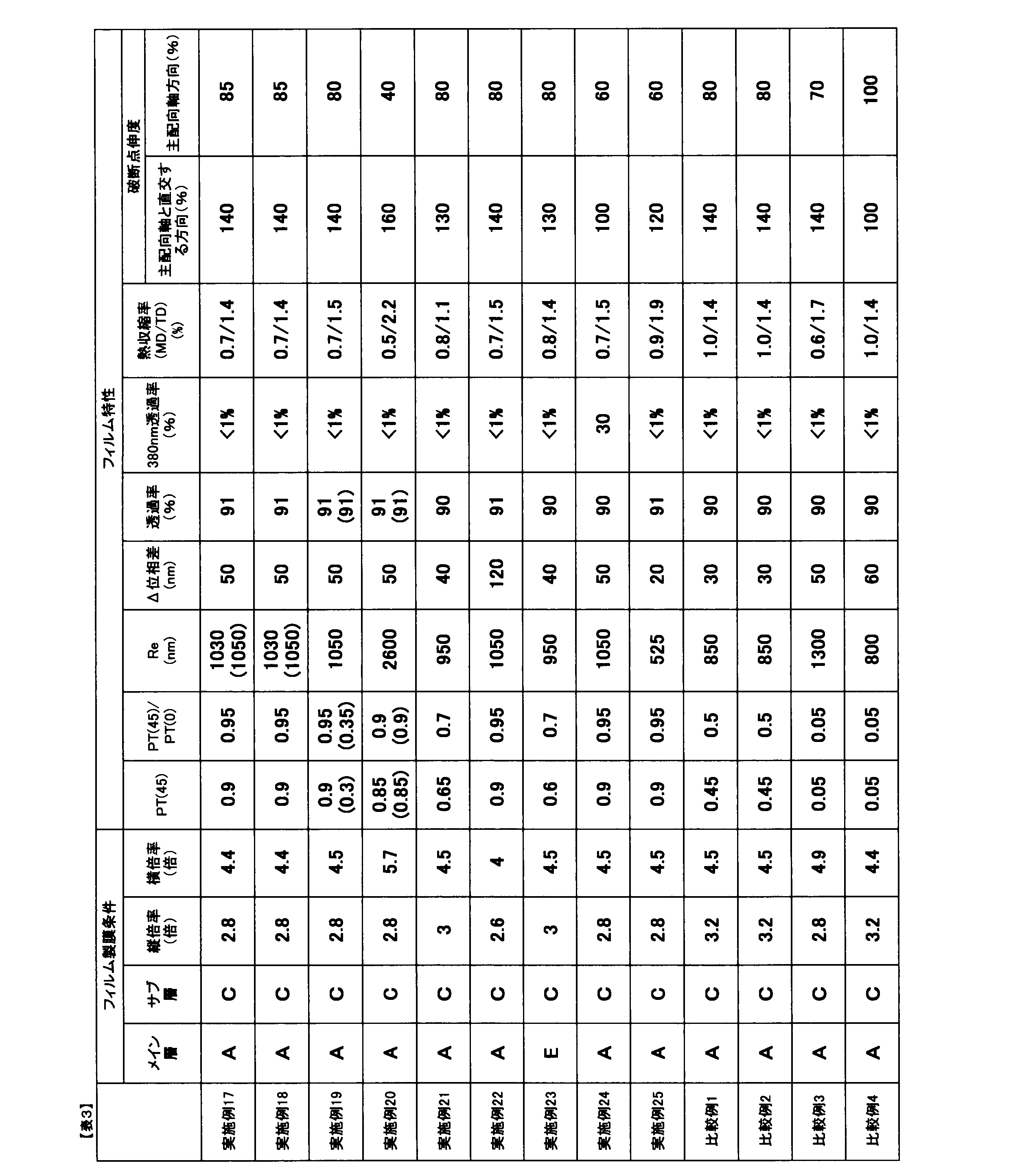
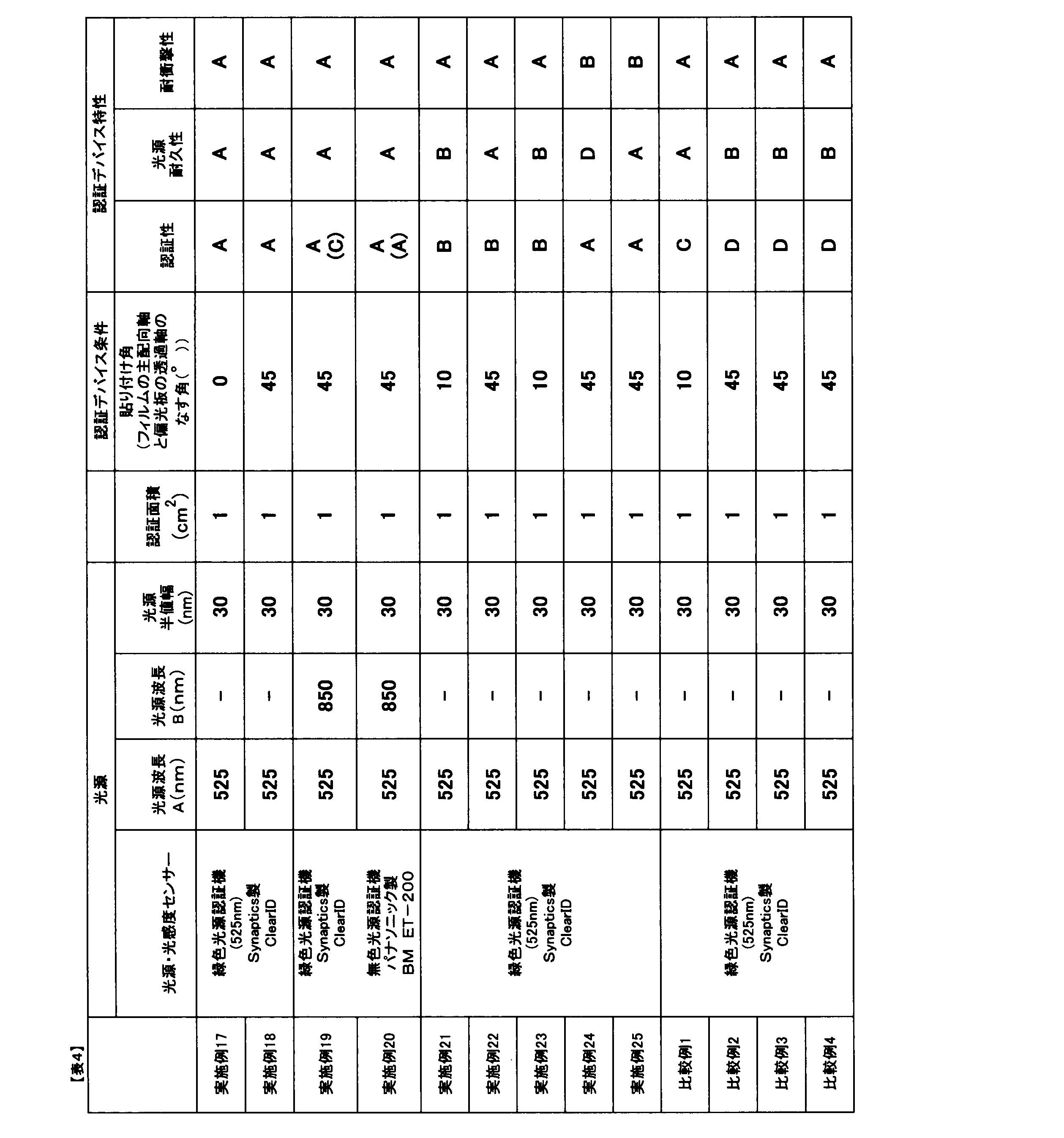
本発明の認証デバイスは、認証性能がフィルムの配向角に依存することなく、紫外線をフィルムが吸収、反射することにより光源、偏光子の耐久性を高めており、また安価なポリエステルをフィルムの原料とすることができるものである。そのため、良好な認証性能と耐久性を有し、安価かつ生産性に優れている。 The authentication device of the present invention has authentication performance that is not dependent on the orientation angle of the film, and the durability of the light source and polarizer is increased by the film absorbing and reflecting ultraviolet light, and inexpensive polyester can be used as the raw material for the film. Therefore, it has good authentication performance and durability, is inexpensive, and has excellent productivity.
1:光源
2:偏光子
3:フィルム
4:光感度センサー
5:光源から射出された光が認証対象物で反射された光
6:光源から射出された光
1: Light source 2: Polarizer 3: Film 4: Light sensitivity sensor 5: Light emitted from the light source and reflected by the object to be authenticated 6: Light emitted from the light source
Claims (15)
(1)前記光源から出射する光線の透過率が、当該光線の最も強い強度の波長において70%以上100%以下であること。
(2)下記(I)式を満足する整数nが存在すること。
(I)A×n-150 ≦ Re ≦ A×n+150
ここで、Aは前記光源から出射する光線において最も強い強度を示す波長(nm)であり、
Reは前記フィルムを平行ニコル回転法を用いて入射角0°での波長587.8nmで測定したときの面内位相差(nm)である。
(3)前記フィルムの面内位相差が400nm以上3000nm以下である。
(4)前記フィルムの主配向軸方向および主配向軸と直交する方向の25℃における破断点伸度がいずれも30%以上300%以下である。
(5)前記光源から出射する光線において最も強い強度を示すピークの半値幅が5nm以上70nm以下である。 An authentication device having a light source, a polarizer, a film, and a light sensitivity sensor for authenticating at least one of a fingerprint, an iris, a face, a handprint, a body shape, and a vein, wherein the film is placed between the polarizer and an object to be authenticated, and the authentication device satisfies the following (1) to (5).
(1) The transmittance of the light beam emitted from the light source is 70% or more and 100% or less at the wavelength at which the light beam has the strongest intensity.
(2) There exists an integer n that satisfies the following formula (I):
(I) A×n-150 ≦ Re ≦ A×n+150
Here, A is the wavelength (nm) at which the light emitted from the light source has the strongest intensity,
Re is the in-plane retardation (nm) of the film measured at a wavelength of 587.8 nm and an incident angle of 0° using the parallel Nicol rotation method.
(3) The in-plane retardation of the film is 400 nm or more and 3,000 nm or less.
(4) The film has an elongation at break at 25° C. in both the main orientation axis direction and the direction perpendicular to the main orientation axis of 30% or more and 300% or less.
(5) The half-width of the peak exhibiting the strongest intensity in the light beam emitted from the light source is 5 nm or more and 70 nm or less.
(II)B×m-150 ≦ Re ≦ B×m+150
ここで、Bは前記光源から出射する光線において2番目に強い強度を示す波長(nm)であり、
Reは前記フィルムを平行ニコル回転法を用いて入射角0°での波長587.8nmで測定したときの面内位相差(nm)である。 The authentication device according to claim 1 , wherein there exists an integer m that satisfies the formula (I) and also satisfies the following formula (II):
(II) B×m-150 ≦ Re ≦ B×m+150
Here, B is the wavelength (nm) exhibiting the second strongest intensity in the light beam emitted from the light source,
Re is the in-plane retardation (nm) of the film measured at a wavelength of 587.8 nm and an incident angle of 0° using the parallel Nicol rotation method.
(III) PT(45) ≧ 0.65
(IV)1 ≧ PT(45)/ PT(0)≧ 0.6
ここで、PT(45)とPT(0)は下記のとおりで求められる。
(1)偏光子を2枚にカットし、2枚の偏光子の面が50Wタングステンランプを光源とした分光光度計の光軸に垂直になるように、かつ2枚の偏光子の透過軸同士が平行になるように配置し、光源消灯状態と光源点灯状態でのバックグラウンド測定を行う。光源消灯状態で測定された透過光量をPT(D)、光源点灯状態で測定された透過光量をPT(L)とする。
(2)2枚の偏光子の間に前記フィルムをフィルムの面が分光光度計の光軸に垂直になるように配置する。
(3)前記フィルムのみを分光光度計の光軸に垂直な面内で回転させつつ、前記光源から出射する光線の最も強い強度を持つ波長における透過光量の測定を行う。2枚の偏光子の透過軸と前記フィルムの主配向軸のなす角が0°のときの透過光量をPT’(0)、45°のときの透過光量をPT’(45)とする。
(4)下記式よりPT(0)、PT(45)を得る。
PT(0)=(PT’(0)- PT(D))/(PT(L)- PT(D))
PT(45)=(PT’(45)- PT(D))/(PT(L)- PT(D))。 The authentication device according to claim 1 or 2, wherein the film satisfies the following formulas (III) and (IV).
(III) PT(45) ≧ 0.65
(IV) 1 ≧ PT (45) / PT (0) ≧ 0.6
Here, PT(45) and PT(0) are calculated as follows.
(1) Cut a polarizer into two pieces, and arrange them so that the surfaces of the two polarizers are perpendicular to the optical axis of a spectrophotometer using a 50 W tungsten lamp as the light source and the transmission axes of the two polarizers are parallel to each other, and perform background measurements with the light source turned off and on. The amount of transmitted light measured with the light source turned off is designated as PT(D), and the amount of transmitted light measured with the light source turned on is designated as PT(L).
(2) The film is placed between two polarizers so that the plane of the film is perpendicular to the optical axis of the spectrophotometer.
(3) While rotating only the film in a plane perpendicular to the optical axis of the spectrophotometer, the amount of transmitted light at the wavelength having the strongest intensity of the light emitted from the light source is measured. The amount of transmitted light when the angle between the transmission axes of the two polarizers and the main alignment axis of the film is 0° is defined as PT'(0), and the amount of transmitted light when the angle is 45° is defined as PT'(45).
(4) PT(0) and PT(45) are obtained from the following formula.
PT(0) = (PT'(0) - PT(D))/(PT(L) - PT(D))
PT(45) = (PT'(45) - PT(D))/(PT(L) - PT(D)).
(V)A×n-120 ≦ Re ≦ A×n+120、 かつ、415 ≦ A ≦ 495。 4. The authentication device according to claim 1, wherein an integer n exists that satisfies the following formula (V):
(V) A×n-120≦Re≦A×n+120, and 415≦A≦495.
(VI)A×n-100 ≦ Re ≦ A×n+100、かつ、495 ≦ A ≦ 570。 4. The authentication device according to claim 1, wherein an integer n exists that satisfies the following formula (VI):
(VI) A×n−100≦Re≦A×n+100, and 495≦A≦570.
(VII)A×n-120 ≦ Re ≦ A×n+120、かつ、570 ≦ A ≦ 800。 4. The authentication device according to claim 1, wherein an integer n exists that satisfies the following formula (VII):
(VII) A×n−120≦Re≦A×n+120, and 570≦A≦800.
(VIII)A×n-150 ≦ Re ≦ A×n+150、かつ、800 ≦ A ≦ 1600。 4. An authentication device according to claim 1, wherein there exists an integer n that satisfies the following formula (VIII):
(VIII) A×n−150≦Re≦A×n+150, and 800≦A≦1600.
Priority Applications (1)
| Application Number | Priority Date | Filing Date | Title |
|---|---|---|---|
| JP2024218343A JP2025031740A (en) | 2019-03-28 | 2024-12-13 | Authentication Devices and Films |
Applications Claiming Priority (3)
| Application Number | Priority Date | Filing Date | Title |
|---|---|---|---|
| JP2019063197 | 2019-03-28 | ||
| JP2019063197 | 2019-03-28 | ||
| PCT/JP2020/012450 WO2020196317A1 (en) | 2019-03-28 | 2020-03-19 | Authentication device and film |
Related Child Applications (1)
| Application Number | Title | Priority Date | Filing Date |
|---|---|---|---|
| JP2024218343A Division JP2025031740A (en) | 2019-03-28 | 2024-12-13 | Authentication Devices and Films |
Publications (3)
| Publication Number | Publication Date |
|---|---|
| JPWO2020196317A1 JPWO2020196317A1 (en) | 2020-10-01 |
| JPWO2020196317A5 JPWO2020196317A5 (en) | 2023-03-14 |
| JP7608830B2 true JP7608830B2 (en) | 2025-01-07 |
Family
ID=72611968
Family Applications (2)
| Application Number | Title | Priority Date | Filing Date |
|---|---|---|---|
| JP2020534999A Active JP7608830B2 (en) | 2019-03-28 | 2020-03-19 | Authentication Devices and Films |
| JP2024218343A Pending JP2025031740A (en) | 2019-03-28 | 2024-12-13 | Authentication Devices and Films |
Family Applications After (1)
| Application Number | Title | Priority Date | Filing Date |
|---|---|---|---|
| JP2024218343A Pending JP2025031740A (en) | 2019-03-28 | 2024-12-13 | Authentication Devices and Films |
Country Status (5)
| Country | Link |
|---|---|
| JP (2) | JP7608830B2 (en) |
| KR (1) | KR20210143754A (en) |
| CN (1) | CN113574427B (en) |
| TW (1) | TWI838492B (en) |
| WO (1) | WO2020196317A1 (en) |
Families Citing this family (1)
| Publication number | Priority date | Publication date | Assignee | Title |
|---|---|---|---|---|
| JP7608830B2 (en) * | 2019-03-28 | 2025-01-07 | 東レ株式会社 | Authentication Devices and Films |
Citations (6)
| Publication number | Priority date | Publication date | Assignee | Title |
|---|---|---|---|---|
| JP2002040249A (en) | 2000-07-25 | 2002-02-06 | Toray Ind Inc | Polyester film for polarizing film lamination |
| JP2003231214A (en) | 2002-10-22 | 2003-08-19 | Teijin Ltd | Release film |
| JP2011118190A (en) | 2009-12-04 | 2011-06-16 | Toray Ind Inc | Polarizing reflector |
| US20140176937A1 (en) | 2011-08-18 | 2014-06-26 | Tiegen Liu | Distributed disturbance sensing device and the related demodulation method based on polarization sensitive optical frequency domain reflectometry |
| JP2018189725A (en) | 2017-04-28 | 2018-11-29 | Jsr株式会社 | Optical filter and imaging apparatus using optical filter |
| JP2018194620A (en) | 2017-05-15 | 2018-12-06 | Jsr株式会社 | Optical filter |
Family Cites Families (6)
| Publication number | Priority date | Publication date | Assignee | Title |
|---|---|---|---|---|
| KR102384787B1 (en) * | 2014-04-09 | 2022-04-08 | 도레이 카부시키가이샤 | Polarizer-protecting polyester film, and polarization plate obtained using same |
| WO2017126153A1 (en) | 2016-01-22 | 2017-07-27 | コニカミノルタ株式会社 | Optical fingerprint authentication device |
| JP7120228B2 (en) * | 2017-05-31 | 2022-08-17 | 日本ゼオン株式会社 | Manufacturing method of retardation film |
| WO2020054529A1 (en) * | 2018-09-12 | 2020-03-19 | 東レ株式会社 | Laminate film |
| KR102532989B1 (en) * | 2018-09-28 | 2023-05-16 | 도요보 가부시키가이샤 | Image display device with fingerprint authentication sensor |
| JP7608830B2 (en) * | 2019-03-28 | 2025-01-07 | 東レ株式会社 | Authentication Devices and Films |
-
2020
- 2020-03-19 JP JP2020534999A patent/JP7608830B2/en active Active
- 2020-03-19 KR KR1020217029171A patent/KR20210143754A/en active Pending
- 2020-03-19 CN CN202080021395.7A patent/CN113574427B/en active Active
- 2020-03-19 WO PCT/JP2020/012450 patent/WO2020196317A1/en not_active Ceased
- 2020-03-23 TW TW109109566A patent/TWI838492B/en active
-
2024
- 2024-12-13 JP JP2024218343A patent/JP2025031740A/en active Pending
Patent Citations (6)
| Publication number | Priority date | Publication date | Assignee | Title |
|---|---|---|---|---|
| JP2002040249A (en) | 2000-07-25 | 2002-02-06 | Toray Ind Inc | Polyester film for polarizing film lamination |
| JP2003231214A (en) | 2002-10-22 | 2003-08-19 | Teijin Ltd | Release film |
| JP2011118190A (en) | 2009-12-04 | 2011-06-16 | Toray Ind Inc | Polarizing reflector |
| US20140176937A1 (en) | 2011-08-18 | 2014-06-26 | Tiegen Liu | Distributed disturbance sensing device and the related demodulation method based on polarization sensitive optical frequency domain reflectometry |
| JP2018189725A (en) | 2017-04-28 | 2018-11-29 | Jsr株式会社 | Optical filter and imaging apparatus using optical filter |
| JP2018194620A (en) | 2017-05-15 | 2018-12-06 | Jsr株式会社 | Optical filter |
Also Published As
| Publication number | Publication date |
|---|---|
| KR20210143754A (en) | 2021-11-29 |
| TWI838492B (en) | 2024-04-11 |
| JPWO2020196317A1 (en) | 2020-10-01 |
| JP2025031740A (en) | 2025-03-07 |
| WO2020196317A1 (en) | 2020-10-01 |
| TW202104949A (en) | 2021-02-01 |
| CN113574427A (en) | 2021-10-29 |
| CN113574427B (en) | 2023-07-14 |
Similar Documents
| Publication | Publication Date | Title |
|---|---|---|
| JP7290111B2 (en) | laminated film | |
| US10018757B2 (en) | Multilayer polymeric reflector | |
| JPH10511322A (en) | Multilayer optical film | |
| CN112771417B (en) | Light source unit, display device, and film | |
| KR20200143402A (en) | Laminated film and display device | |
| KR20200115495A (en) | Multilayer reflective polarizer with crystalline low refractive index layer | |
| JP2025031740A (en) | Authentication Devices and Films | |
| TW202031504A (en) | Multilayer reflective polarizer with crystalline low index layers | |
| KR102749234B1 (en) | Laminate and its manufacturing method, light guide plate unit, light source unit, display device, projection image display member, projection image display device and filter for display screen | |
| JP6891493B2 (en) | Multi-layer laminated film | |
| CN117897638A (en) | Multilayer laminated film and projection image display component | |
| CN116997835A (en) | Optical films and optical systems | |
| JP7494634B2 (en) | Image detection device and information device using same | |
| JP7259207B2 (en) | the film | |
| WO2022070512A1 (en) | Retardation film, polarizing plate with retardation layer, and image display device |
Legal Events
| Date | Code | Title | Description |
|---|---|---|---|
| A521 | Request for written amendment filed |
Free format text: JAPANESE INTERMEDIATE CODE: A523 Effective date: 20230306 |
|
| A621 | Written request for application examination |
Free format text: JAPANESE INTERMEDIATE CODE: A621 Effective date: 20230306 |
|
| A131 | Notification of reasons for refusal |
Free format text: JAPANESE INTERMEDIATE CODE: A131 Effective date: 20231121 |
|
| A521 | Request for written amendment filed |
Free format text: JAPANESE INTERMEDIATE CODE: A523 Effective date: 20240119 |
|
| A131 | Notification of reasons for refusal |
Free format text: JAPANESE INTERMEDIATE CODE: A131 Effective date: 20240507 |
|
| A601 | Written request for extension of time |
Free format text: JAPANESE INTERMEDIATE CODE: A601 Effective date: 20240702 |
|
| A521 | Request for written amendment filed |
Free format text: JAPANESE INTERMEDIATE CODE: A523 Effective date: 20240826 |
|
| TRDD | Decision of grant or rejection written | ||
| A01 | Written decision to grant a patent or to grant a registration (utility model) |
Free format text: JAPANESE INTERMEDIATE CODE: A01 Effective date: 20241119 |
|
| A61 | First payment of annual fees (during grant procedure) |
Free format text: JAPANESE INTERMEDIATE CODE: A61 Effective date: 20241202 |
|
| R150 | Certificate of patent or registration of utility model |
Ref document number: 7608830 Country of ref document: JP Free format text: JAPANESE INTERMEDIATE CODE: R150 |