KR20200115495A - Multilayer reflective polarizer with crystalline low refractive index layer - Google Patents
Multilayer reflective polarizer with crystalline low refractive index layer Download PDFInfo
- Publication number
- KR20200115495A KR20200115495A KR1020207020849A KR20207020849A KR20200115495A KR 20200115495 A KR20200115495 A KR 20200115495A KR 1020207020849 A KR1020207020849 A KR 1020207020849A KR 20207020849 A KR20207020849 A KR 20207020849A KR 20200115495 A KR20200115495 A KR 20200115495A
- Authority
- KR
- South Korea
- Prior art keywords
- reflective polarizer
- multilayer reflective
- polymer layers
- layers
- refractive index
- Prior art date
Links
Images


Classifications
-
- G—PHYSICS
- G02—OPTICS
- G02B—OPTICAL ELEMENTS, SYSTEMS OR APPARATUS
- G02B5/00—Optical elements other than lenses
- G02B5/30—Polarising elements
- G02B5/3025—Polarisers, i.e. arrangements capable of producing a definite output polarisation state from an unpolarised input state
- G02B5/3033—Polarisers, i.e. arrangements capable of producing a definite output polarisation state from an unpolarised input state in the form of a thin sheet or foil, e.g. Polaroid
- G02B5/3041—Polarisers, i.e. arrangements capable of producing a definite output polarisation state from an unpolarised input state in the form of a thin sheet or foil, e.g. Polaroid comprising multiple thin layers, e.g. multilayer stacks
- G02B5/305—Polarisers, i.e. arrangements capable of producing a definite output polarisation state from an unpolarised input state in the form of a thin sheet or foil, e.g. Polaroid comprising multiple thin layers, e.g. multilayer stacks including organic materials, e.g. polymeric layers
-
- B—PERFORMING OPERATIONS; TRANSPORTING
- B32—LAYERED PRODUCTS
- B32B—LAYERED PRODUCTS, i.e. PRODUCTS BUILT-UP OF STRATA OF FLAT OR NON-FLAT, e.g. CELLULAR OR HONEYCOMB, FORM
- B32B27/00—Layered products comprising a layer of synthetic resin
- B32B27/36—Layered products comprising a layer of synthetic resin comprising polyesters
-
- C—CHEMISTRY; METALLURGY
- C08—ORGANIC MACROMOLECULAR COMPOUNDS; THEIR PREPARATION OR CHEMICAL WORKING-UP; COMPOSITIONS BASED THEREON
- C08G—MACROMOLECULAR COMPOUNDS OBTAINED OTHERWISE THAN BY REACTIONS ONLY INVOLVING UNSATURATED CARBON-TO-CARBON BONDS
- C08G63/00—Macromolecular compounds obtained by reactions forming a carboxylic ester link in the main chain of the macromolecule
- C08G63/02—Polyesters derived from hydroxycarboxylic acids or from polycarboxylic acids and polyhydroxy compounds
- C08G63/12—Polyesters derived from hydroxycarboxylic acids or from polycarboxylic acids and polyhydroxy compounds derived from polycarboxylic acids and polyhydroxy compounds
- C08G63/16—Dicarboxylic acids and dihydroxy compounds
- C08G63/18—Dicarboxylic acids and dihydroxy compounds the acids or hydroxy compounds containing carbocyclic rings
- C08G63/181—Acids containing aromatic rings
- C08G63/183—Terephthalic acids
-
- C—CHEMISTRY; METALLURGY
- C08—ORGANIC MACROMOLECULAR COMPOUNDS; THEIR PREPARATION OR CHEMICAL WORKING-UP; COMPOSITIONS BASED THEREON
- C08G—MACROMOLECULAR COMPOUNDS OBTAINED OTHERWISE THAN BY REACTIONS ONLY INVOLVING UNSATURATED CARBON-TO-CARBON BONDS
- C08G63/00—Macromolecular compounds obtained by reactions forming a carboxylic ester link in the main chain of the macromolecule
- C08G63/91—Polymers modified by chemical after-treatment
- C08G63/914—Polymers modified by chemical after-treatment derived from polycarboxylic acids and polyhydroxy compounds
- C08G63/916—Dicarboxylic acids and dihydroxy compounds
-
- C—CHEMISTRY; METALLURGY
- C08—ORGANIC MACROMOLECULAR COMPOUNDS; THEIR PREPARATION OR CHEMICAL WORKING-UP; COMPOSITIONS BASED THEREON
- C08L—COMPOSITIONS OF MACROMOLECULAR COMPOUNDS
- C08L67/00—Compositions of polyesters obtained by reactions forming a carboxylic ester link in the main chain; Compositions of derivatives of such polymers
- C08L67/02—Polyesters derived from dicarboxylic acids and dihydroxy compounds
-
- G—PHYSICS
- G02—OPTICS
- G02B—OPTICAL ELEMENTS, SYSTEMS OR APPARATUS
- G02B1/00—Optical elements characterised by the material of which they are made; Optical coatings for optical elements
- G02B1/04—Optical elements characterised by the material of which they are made; Optical coatings for optical elements made of organic materials, e.g. plastics
-
- G—PHYSICS
- G02—OPTICS
- G02C—SPECTACLES; SUNGLASSES OR GOGGLES INSOFAR AS THEY HAVE THE SAME FEATURES AS SPECTACLES; CONTACT LENSES
- G02C7/00—Optical parts
- G02C7/12—Polarisers
-
- G—PHYSICS
- G02—OPTICS
- G02B—OPTICAL ELEMENTS, SYSTEMS OR APPARATUS
- G02B27/00—Optical systems or apparatus not provided for by any of the groups G02B1/00 - G02B26/00, G02B30/00
- G02B27/01—Head-up displays
- G02B2027/0192—Supplementary details
- G02B2027/0196—Supplementary details having transparent supporting structure for display mounting, e.g. to a window or a windshield
-
- G—PHYSICS
- G02—OPTICS
- G02B—OPTICAL ELEMENTS, SYSTEMS OR APPARATUS
- G02B27/00—Optical systems or apparatus not provided for by any of the groups G02B1/00 - G02B26/00, G02B30/00
- G02B27/01—Head-up displays
- G02B27/0101—Head-up displays characterised by optical features
Abstract
다층 반사 편광기들이 기술된다. 특히, 결정질 고 굴절률 층들 및 저 굴절률 층들 둘 모두를 포함하는 다층 반사 편광기들이 개시된다. 이들 반사 편광기는, 요구가 많은 주변 환경을 갖는 자동차 헤드 업 디스플레이 응용을 포함한 컴바이너 응용에 특히 적합할 수 있다. 층들은 PET 및 PETG로 제조된다.Multilayer reflective polarizers are described. In particular, multilayer reflective polarizers are disclosed that include both crystalline high index layers and low index layers. These reflective polarizers may be particularly suitable for combiner applications, including automotive head-up display applications with demanding surroundings. The layers are made of PET and PETG.
Description
다층 반사 편광기는, 교번하는 중합체 층들 사이의 굴절률의 차이가 하나의 직교 편광의 광이 실질적으로 반사되게 하는 반면에 다른 하나가 실질적으로 투과되도록 배향된, 교번하는 중합체 층들로 대체로 형성된 광학 필름이다. 층 스택(stack) 설계 및 재료 선택을 통해, 다층 반사 편광기는 원하는 범위의 가시광 및 적외선 파장에 걸쳐 광을 편광시킬 수 있다.A multilayer reflective polarizer is an optical film generally formed of alternating polymer layers oriented such that the difference in refractive index between alternating polymer layers causes light of one orthogonal polarization to be substantially reflected while the other is substantially transmitted. Through layer stack design and material selection, multilayer reflective polarizers can polarize light over a desired range of visible and infrared wavelengths.
일 태양에서, 본 발명은 다층 반사 편광기에 관한 것이다. 다층 반사 편광기는 복수의 교번하는 제1 중합체 층들 및 제2 중합체 층들을 포함한다. 제1 중합체 층들은 폴리에틸렌 테레프탈레이트를 포함하고, 제2 중합체 층들은 글리콜-개질된 코(폴리에틸렌 테레프탈레이트)를 포함한다. 제1 중합체 층들 및 제2 중합체 층들 둘 모두의 총 광학 두께에 대한 제1 중합체 층들의 평균 광학 두께의 비로서 정의되는 다층 반사 편광기의 f-비는 0.55 이상이다.In one aspect, the present invention relates to a multilayer reflective polarizer. The multilayer reflective polarizer includes a plurality of alternating first polymer layers and second polymer layers. The first polymer layers comprise polyethylene terephthalate and the second polymer layers comprise glycol-modified co (polyethylene terephthalate). The f-ratio of the multilayer reflective polarizer, defined as the ratio of the average optical thickness of the first polymer layers to the total optical thickness of both the first polymer layers and the second polymer layers, is at least 0.55.
다른 태양에서, 본 발명은 다층 반사 편광기에 관한 것이다. 다층 반사 편광기는 복수의 교번하는 제1 중합체 층들 및 제2 중합체 층들을 포함한다. 제1 중합체 층들 및 제2 중합체 층들 각각은 0.04 이상의 평면내 복굴절을 갖는다. 적어도 하나의 평면내 방향에 대해, 제1 중합체 층들과 제2 중합체 층들 각각 사이의 굴절률 차이가 0.04 이상이다. 상기 적어도 하나의 평면내 방향에 직교하는 제2 평면내 방향에 대해, 제1 중합체 층들과 제2 중합체 층들 각각 사이의 굴절률 차이가 0.04 미만이다.In another aspect, the present invention relates to a multilayer reflective polarizer. The multilayer reflective polarizer includes a plurality of alternating first polymer layers and second polymer layers. Each of the first and second polymer layers has an in-plane birefringence of 0.04 or more. For at least one in-plane direction, the difference in refractive index between each of the first polymer layers and the second polymer layers is at least 0.04. For a second in-plane direction orthogonal to the at least one in-plane direction, the difference in refractive index between each of the first polymer layers and the second polymer layers is less than 0.04.
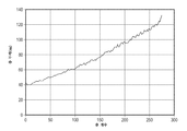
도 1은 실시예 1에 대한 층 두께 프로파일의 그래프.
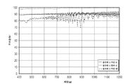
도 2는 실시예 1에 대한 투과율 스펙트럼의 그래프.
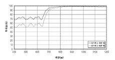
도 3은 실시예 1에 대한 열 응력 노출 전후의 60도 입사에서의 p-편광 차단 상태 투과율의 그래프.
도 4는 실시예 2에 대한 층 두께 프로파일의 그래프.
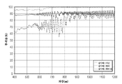
도 5는 실시예 2에 대한 투과율 스펙트럼의 그래프.
도 6은 실시예 2에 대한 열 응력 노출 전후의 60도 입사에서의 p-편광 차단 상태 투과율의 그래프.
도 7은 실시예 3에 대한 층 두께 프로파일의 그래프.
도 8은 실시예 3에 대한 투과율 스펙트럼의 그래프.
도 9는 실시예 3에 대한 열 응력 노출 전후의 60도 입사에서의 p-편광 차단 상태 투과율의 그래프.
도 10은 유리 시트들 사이에서의 실시예 4에 대한 투과율 스펙트럼의 그래프.
도 11은 유리 시트들 사이에서의 실시예 5에 대한 투과율 스펙트럼의 그래프.
도 12는 PVB 중간층을 갖는 2개의 유리 층에 대한 투과율 스펙트럼의 그래프.1 is a graph of the layer thickness profile for Example 1. FIG.
2 is a graph of the transmittance spectrum for Example 1.
3 is a graph of the transmittance of the p-polarized light blocking state at 60 degrees incidence before and after exposure to thermal stress for Example 1. FIG.
4 is a graph of the layer thickness profile for Example 2.
5 is a graph of the transmittance spectrum for Example 2.
6 is a graph of the p-polarized light blocking state transmittance at 60 degrees incidence before and after exposure to thermal stress for Example 2. FIG.
7 is a graph of the layer thickness profile for Example 3.
8 is a graph of the transmittance spectrum for Example 3.
9 is a graph of the transmittance of the p-polarized light blocking state at 60 degree incidence before and after exposure to thermal stress for Example 3. FIG.
10 is a graph of the transmittance spectrum for Example 4 between glass sheets.
11 is a graph of the transmittance spectrum for Example 5 between glass sheets.
12 is a graph of transmittance spectra for two glass layers with a PVB interlayer.
다층 광학 필름, 즉 상이한 굴절률의 미세층의 배열에 의해 적어도 부분적으로 바람직한 투과 및/또는 반사 특성을 제공하는 필름이 알려져 있다. 진공 챔버 내에서 기재(substrate) 상에 광학적으로 얇은 층("미세층")으로 일련의 무기 재료를 침착시킴으로써 그러한 다층 광학 필름을 제조하는 것이 알려져 있다. 무기 다층 광학 필름은, 예를 들어 문헌[H. A. Macleod, Thin-Film Optical Filters, 2nd Ed., Macmillan Publishing Co. (1986) and by A. Thelan, Design of Optical Interference Filters, McGraw-Hill, Inc. (1989)]의 교재에 기술되어 있다.Multilayer optical films are known, ie films that provide desirable transmission and/or reflection properties at least in part by an arrangement of microlayers of different refractive indices. It is known to make such multilayer optical films by depositing a series of inorganic materials in an optically thin layer (“fine layer”) on a substrate in a vacuum chamber. Inorganic multilayer optical films are described, for example, in HA Macleod, Thin-Film Optical Filters, 2nd Ed . , Macmillan Publishing Co. (1986) and by A. Thelan, Design of Optical Interference Filters , McGraw-Hill, Inc. (1989)].
다층 광학 필름은 또한 교번하는 중합체 층들의 공압출에 의해 입증되었다. 예컨대, 미국 특허 제3,610,729호(로저스(Rogers)), 제4,446,305호(로저스 등), 제4,540,623호(임(Im) 등), 제5,448,404호(슈렝크(Schrenk) 등), 및 제5,882,774호(존자(Jonza) 등)를 참조한다. 이들 중합체 다층 광학 필름에서, 중합체 재료가 개별 층의 구성에 주로 또는 전적으로 사용된다. 그러한 필름은 대량 제조 공정에 적합하고 대형 시트(sheet) 및 롤(roll) 제품으로 제조될 수 있다.Multilayer optical films were also demonstrated by coextrusion of alternating polymer layers. For example, U.S. Patent Nos. 3,610,729 (Rogers), 4,446,305 (Rogers et al.), 4,540,623 (Im et al.), 5,448,404 (Schrenk et al.), and 5,882,774 ( Jonza et al.). In these polymeric multilayer optical films, polymeric materials are mainly or exclusively used in the construction of the individual layers. Such films are suitable for high-volume manufacturing processes and can be made into large sheet and roll products.
다층 광학 필름은 일부 광이 인접한 미세층들 사이의 계면에서 반사되도록 상이한 굴절률 특성을 갖는 개별 미세층을 포함한다. 미세층은 다층 광학 필름에 원하는 반사 또는 투과 특성을 제공하기 위해 복수의 계면에서 반사된 광이 보강 또는 상쇄 간섭을 겪도록 충분히 얇다. 자외선, 가시광, 또는 근적외선 파장에서 광을 반사시키도록 설계된 다층 광학 필름의 경우, 각각의 미세층은 대체적으로 약 1 μm 미만의 광학 두께(즉, 물리적 두께에 굴절률을 곱한 것)를 갖는다. 다층 광학 필름의 외부 표면에 있는 스킨 층, 또는 미세층들의 일관된 그룹(본 명세서에서는 "패킷"으로 지칭됨)을 분리시키는 다층 광학 필름 내에 배치된 보호 경계 층(protective boundary layer, PBL)과 같은 두꺼운 층이 포함될 수 있다.Multilayer optical films include individual microlayers with different refractive index properties such that some light is reflected at the interface between adjacent microlayers. The microlayer is thin enough so that light reflected from a plurality of interfaces undergoes constructive or destructive interference to provide the desired reflective or transmissive properties to the multilayer optical film. For multilayer optical films designed to reflect light at ultraviolet, visible, or near infrared wavelengths, each microlayer typically has an optical thickness of less than about 1 μm (i.e., the physical thickness times the refractive index). A skin layer on the outer surface of a multilayer optical film, or thick, such as a protective boundary layer (PBL) disposed within a multilayer optical film that separates a coherent group of microlayers (referred to herein as "packets"). Layers may be included.
편광 응용의 경우, 예컨대 반사 편광기의 경우, 광학 층들 중 적어도 일부는 중합체의 굴절률이 중합체의 직교좌표축들을 따라 상이한 값들을 갖는 복굴절 중합체를 사용하여 형성된다. 일반적으로, 복굴절 중합체 미세층은 층 평면에 대한 법선(z-축)에 의해 정의되는 직교좌표축을 가지며, 여기서 x-축 및 y-축은 층 평면 내에 있다. 복굴절 중합체는 또한 비편광 응용에서 사용될 수 있다.For polarization applications, such as reflective polarizers, at least some of the optical layers are formed using a birefringent polymer in which the refractive index of the polymer has different values along the orthogonal coordinate axes of the polymer. In general, the birefringent polymer microlayer has a Cartesian coordinate axis defined by a normal to the layer plane (z-axis), where the x-axis and y-axis are within the layer plane. Birefringent polymers can also be used in non-polarization applications.
일부 경우에서, 미세층은 1/4 파장 스택에 대응하는 두께 및 굴절률 값을 갖는데, 즉, 이들은 각각이 동일한 광학 두께(f-비 = 50%)의 2개의 인접한 미세층을 갖는 광학 반복 유닛 또는 유닛 셀 내에 배열되며, 그러한 광학 반복 유닛은 파장 λ가 광학 반복 유닛의 전체 광학 두께의 2배인 보강 간섭광에 의한 반사에 효과적이다. 다른 층 배열, 예컨대 그의 f-비가 50%와 상이한 2-미세층 광학 반복 유닛을 갖는 다층 광학 필름, 또는 그의 광학 반복 유닛이 2개 초과의 미세층을 포함하는 필름이 또한 알려져 있다. 이들 광학 반복 유닛 설계는 소정의 고차 반사(higher-order reflection)를 감소시키거나 증가시키도록 구성될 수 있다. 예를 들어, 미국 특허 제5,360,659호(아렌즈(Arends) 등) 및 제5,103,337호(슈렝크 등)를 참조한다. 사람의 가시 영역 전체에 걸쳐 그리고 근적외선 내로 연장되는 반사 대역과 같은 확장된 반사 대역을 제공하도록 필름의 두께 축(예를 들어, z-축)을 따른 두께 구배가 이용될 수 있어, 이 대역이 경사 입사각에서 보다 짧은 파장으로 이동될 때 미세층 스택이 전체 가시 스펙트럼에 걸쳐 계속하여 반사하도록 한다. 대역 에지, 즉 고 반사와 고 투과 사이의 파장 전이를 선명하게 하도록 맞춰진 두께 구배가 미국 특허 제6,157,490호(휘틀리(Wheatley) 등)에 논의되어 있다.In some cases, the microlayers have a thickness and refractive index value corresponding to a quarter wavelength stack, i.e., they each have an optical repeating unit or two adjacent microlayers of the same optical thickness (f-ratio = 50%). Arranged in the unit cell, such an optical repeating unit is effective for reflection by constructive interference light whose wavelength λ is twice the total optical thickness of the optical repeating unit. Other layer arrangements, such as multilayer optical films having two-microlayer optical repeating units whose f-ratio differs from 50%, or films whose optical repeating units comprise more than two microlayers, are also known. These optical repeat unit designs can be configured to reduce or increase certain higher-order reflections. See, for example, U.S. Patent Nos. 5,360,659 (Arends et al.) and 5,103,337 (Schrenk et al.). A thickness gradient along the film's thickness axis (e.g., the z-axis) can be used to provide an extended reflective band, such as a reflective band that extends throughout the human visible area and into the near-infrared, so that this band is tilted. It causes the microlayer stack to continue to reflect across the entire visible spectrum as it is shifted to a shorter wavelength at the angle of incidence. A thickness gradient tailored to sharpen the band edge, ie the wavelength transition between high reflection and high transmission, is discussed in US Pat. No. 6,157,490 (Wheatley et al.).
다층 광학 필름 및 관련된 설계와 구조의 추가의 상세 사항이 미국 특허 제5,882,774호(존자 등) 및 제6,531,230호(웨버(Weber) 등), PCT 공개 WO 95/17303호(오더커크(Ouderkirk) 등) 및 WO 99/39224호(오더커크 등), 및 문헌["Giant Birefringent Optics in Multilayer Polymer Mirrors", Science, Vol. 287, March 2000 (Weber et al.)]에 논의되어 있다. 다층 광학 필름 및 관련된 물품은 그들의 광학적, 기계적, 및/또는 화학적 특성을 위해 선택되는 추가의 층 및 코팅을 포함할 수 있다. 예를 들어, UV 흡수 층이 구성요소를 UV 광에 의해 유발되는 열화로부터 보호하기 위해 필름의 입사 면에 추가될 수 있다. 다층 광학 필름은 UV-경화성 아크릴레이트 접착제 또는 다른 적합한 재료를 사용하여 기계적 강화 층에 부착될 수 있다. 그러한 강화 층은 PET 또는 폴리카르보네이트와 같은 중합체를 포함할 수 있고, 또한 예컨대 비드(bead) 또는 프리즘의 사용에 의해, 광 확산 또는 시준과 같은 광학 기능을 제공하는 구조화된 표면을 포함할 수 있다. 추가의 층 및 코팅은 또한 내스크래치성 층(scratch resistant layer), 내인열성 층(tear resistant layer), 및 경화제(stiffening agent)를 포함할 수 있다. 예컨대, 미국 특허 제6,368,699호(길버트(Gilbert) 등)를 참조한다. 다층 광학 필름을 제조하기 위한 방법 및 장치가 미국 특허 제6,783,349호(네빈(Neavin) 등)에 논의되어 있다.Further details of the multilayer optical film and related designs and structures can be found in U.S. Patent Nos. 5,882,774 (Zonza et al.) and 6,531,230 (Weber et al.), PCT Publication WO 95/17303 (Ouderkirk et al.) And WO 99/39224 (Orderkirk et al.), and in "Giant Birefringent Optics in Multilayer Polymer Mirrors", Science, Vol. 287, March 2000 (Weber et al.). Multilayer optical films and related articles may include additional layers and coatings selected for their optical, mechanical, and/or chemical properties. For example, a UV absorbing layer can be added to the incident side of the film to protect the component from degradation caused by UV light. The multilayer optical film can be attached to the mechanical strengthening layer using a UV-curable acrylate adhesive or other suitable material. Such a reinforcing layer may comprise a polymer such as PET or polycarbonate, and may also comprise a structured surface that provides optical functions such as light diffusion or collimation, such as by the use of beads or prisms. have. Additional layers and coatings may also include a scratch resistant layer, a tear resistant layer, and a stiffening agent. See, for example, US Pat. No. 6,368,699 (Gilbert et al.). Methods and apparatus for making multilayer optical films are discussed in US Pat. No. 6,783,349 (Neavin et al.).
다층 광학 필름의 반사 및 투과 특성들은 각각의 미세층의 굴절률 및 미세층의 두께와 두께 분포의 함수이다. 각각의 미세층은 적어도 필름 내의 국소화된 위치에서, 평면내 굴절률 nx, ny, 및 필름의 두께 축과 연관된 굴절률 nz에 의해 특징지어질 수 있다. 이들 굴절률은 각각 상호 직교하는 x-축, y-축, 및 z-축을 따라 편광되는 광에 대한 당해 재료의 굴절률을 나타낸다. 본 특허 출원에서 설명의 용이함을 위해, 달리 특정되지 않는 한, x-축, y-축, 및 z-축은 다층 광학 필름 상의 관심대상의 임의의 지점에 적용가능한 국소 직교좌표인 것으로 가정되며, 여기서 미세층은 x-y 평면에 평행하게 연장되고, x-축은 Δnx의 크기를 최대화하도록 필름의 평면 내에 배향된다. 따라서, Δny의 크기는 Δnx의 크기 이하 - 그러나, 초과하지는 않음 - 일 수 있다. 또한, 차이 Δnx, Δny, Δnz를 계산함에 있어서 어떤 재료 층으로 시작할지의 선택은 Δnx가 음이 되지 않을 것을 요구함으로써 정해진다. 다시 말하면, 계면을 형성하는 2개의 층들 사이의 굴절률 차이가 Δnj = n1j - n2j이고, 여기서 j = x, y, 또는 z이고, 층의 번호 1, 2는 n1x ≥ n2x, 즉 Δnx ≥ 0이 되도록 선택된다.The reflection and transmission properties of the multilayer optical film are a function of the refractive index of each microlayer and the thickness and thickness distribution of the microlayer. Each microlayer may be characterized by an in-plane refractive index n x , n y , and a refractive index n z associated with the thickness axis of the film, at least at a localized location within the film. These refractive indices represent the refractive index of the material for light polarized along the x-axis, y-axis, and z-axis, respectively, which are orthogonal to each other. For ease of explanation in this patent application, unless otherwise specified, the x-axis, y-axis, and z-axis are assumed to be local Cartesian coordinates applicable to any point of interest on the multilayer optical film, where The microlayer extends parallel to the xy plane, and the x-axis is oriented in the plane of the film to maximize the size of Δn x . Thus, the size of Δn y may be less than-but not exceeding-the size of Δn x . Also, in calculating the differences Δn x , Δn y , and Δn z , the choice of which material layer to start with is determined by requiring that Δn x not be negative. In other words, the difference in refractive index between the two layers forming the interface is Δn j = n 1j -n 2j , where j = x, y, or z, and the number of
실제로, 굴절률은 적절한 재료 선택 및 처리 조건에 의해 제어된다. 종래의 다층 필름은 2개의 교번하는 중합체(A, B)를 많은, 예를 들어 수십 또는 수백 개의 층들로 공압출하고, 가능하게는 이어서 다층 압출물을 하나 이상의 다중화 다이로 통과시키며, 그리고 나서 최종 필름을 형성하도록 압출물을 연신 또는 달리 배향시킴으로써 제조된다. 생성된 필름은 전형적으로, 가시광 또는 근적외선에서와 같은 원하는 스펙트럼 영역(들) 내에서 하나 이상의 반사 대역을 제공하도록 두께 및 굴절률이 조정된 많은 - 기백 또는 수백 개의 - 개별 미세층으로 구성된다. 적당한 개수의 층에 의한 원하는 반사율을 달성하기 위해, 인접한 미세층들은 전형적으로 x-축을 따라 편광되는 광에 대해 0.04 이상의 굴절률 차이(Δnx)를 나타낸다. 일부 실시 형태에서, 재료는 x-축을 따라 편광되는 광에 대한 굴절률 차이가 배향 후에 가능한 한 크도록 선택된다. 2개의 직교하는 편광에 대해 반사율이 요구되는 경우, 인접한 미세층들은 또한 y-축을 따라 편광되는 광에 대해 0.04 이상의 굴절률 차이(Δny)를 나타내도록 제조될 수 있다.In practice, the refractive index is controlled by appropriate material selection and processing conditions. Conventional multilayer films coextrusion two alternating polymers (A, B) into many, for example tens or hundreds of layers, possibly then passing the multilayer extrudate through one or more multiplexing dies, and then final It is prepared by stretching or otherwise orienting the extrudate to form a film. The resulting film is typically composed of many-white or hundreds-individual microlayers whose thickness and refractive index have been adjusted to provide one or more bands of reflection within the desired spectral region(s), such as in visible or near infrared. In order to achieve the desired reflectivity with an appropriate number of layers, adjacent microlayers typically exhibit a refractive index difference (Δn x ) of at least 0.04 for light polarized along the x-axis. In some embodiments, the material is selected such that the difference in index of refraction for light polarized along the x-axis is as large as possible after orientation. If reflectance is required for two orthogonal polarizations, adjacent microlayers can also be fabricated to exhibit a refractive index difference (Δn y ) of 0.04 or more for light polarized along the y-axis.
위에서 참조된 '774호(존자 등) 특허는 특히 z-축을 따라 편광되는 광에 대한 인접한 미세층들 사이의 굴절률 차이(Δnz)가 경사 입사 광의 p-편광 성분에 대한 바람직한 반사율 특성을 달성하도록 맞춰질 수 있는 방법을 기술한다. 경사 입사각에서의 p-편광된 광의 고 반사율을 유지하기 위해, 미세층들 사이의 z-굴절률 부정합 Δnz는 최대 평면내 굴절률 차이 Δnx보다 실질적으로 작도록 제어될 수 있고, 따라서 Δnz ≤ 0.5 * Δnx, 또는 Δnz ≤ 0.25 * Δnx가 된다. 0 또는 거의 0인 크기의 z-굴절률 부정합은 p-편광된 광에 대한 그의 반사율이 입사각의 함수로서 일정하거나 거의 일정한 미세층들 사이의 계면을 생성한다. 또한, z-굴절률 부정합 Δnz는 평면내 굴절률 차이 Δnx와 비교해 반대 극성을 갖도록, 즉 Δnz < 0이 되도록 제어될 수 있다. 이러한 조건은, s-편광된 광에 대해 그러한 바와 같이, p-편광된 광에 대한 그의 반사율이 입사각이 증가함에 따라 증가하는 계면을 생성한다.The '774 (Zonza et al.) patent referenced above specifically ensures that the difference in refractive index (Δn z ) between adjacent microlayers for light polarized along the z-axis achieves desirable reflectance characteristics for the p-polarized component of obliquely incident light. Describe how it can be fit. In order to maintain high reflectivity of p-polarized light at an oblique angle of incidence, the z-refractive index mismatch Δn z between microlayers can be controlled to be substantially less than the maximum in-plane refractive index difference Δn x , and thus Δn z ≤ 0.5 * Δn x , or Δn z ≤ 0.25 * Δn x . A z-refractive index mismatch of magnitude zero or near zero creates an interface between microlayers whose reflectivity for p-polarized light is constant or nearly constant as a function of the angle of incidence. In addition, the z-refractive index mismatch Δn z may be controlled to have an opposite polarity compared to the in-plane refractive index difference Δn x , that is, Δn z <0. This condition creates an interface in which its reflectivity for p-polarized light increases as the angle of incidence increases, as for s-polarized light.
'774 특허(존자 등)는 또한, 다층 반사형 또는 반사 편광기로 지칭되는 편광기로서 구성되는 다층 광학 필름에 관한 소정의 설계 고려사항들을 논의한다. 많은 응용에서, 이상적인 반사 편광기는 하나의 축("소광" 또는 "차단" 축)을 따라 고 반사율을, 그리고 다른 축("투과" 또는 "통과" 축)을 따라 0의 반사율을 갖는다. 이러한 응용의 목적을 위해, 편광 상태가 통과 축 또는 투과 축과 실질적으로 정렬되는 광은 통과 광이라고 지칭되고, 편광 상태가 차단 축 또는 소광 축과 실질적으로 정렬되는 광은 차단 광이라고 지칭된다. 달리 표시되지 않는다면, 60° 입사에서의 통과 광은 p-편광된 통과 광에서 측정된다. 일부 반사가 투과 축을 따라 일어나면, 비-수직(off-normal) 각도에서의 편광기의 효율이 감소될 수 있고, 반사율이 다양한 파장에 대해 상이하면, 투과된 광 내로 색상이 도입될 수 있다. 게다가, 2개의 y 굴절률 및 2개의 z 굴절률의 정확한 정합은 일부 다층 시스템에서 가능하지 않을 수 있으며, z-축 굴절률이 정합되지 않으면, 평면내 굴절률(n1y, n2y)에 대해 약간의 부정합의 도입이 요구될 수 있다. 특히, y-굴절률 부정합을 z-굴절률 부정합과 동일한 부호를 갖도록 조정함으로써, 브루스터(Brewster) 효과가 미세층들의 계면에서 생성되어, 다층 반사 편광기의 투과 축을 따라 축외(off-axis) 반사율 및 따라서 축외 색상을 최소화시킨다.The '774 patent (Zonza et al.) also discusses certain design considerations for multilayer optical films configured as polarizers referred to as multilayer reflective or reflective polarizers. In many applications, an ideal reflective polarizer has a high reflectivity along one axis (“extinction” or “blocking” axis) and zero reflectance along the other axis (“transmit” or “pass” axis). For the purposes of this application, light whose polarization state is substantially aligned with the pass axis or transmission axis is referred to as passing light, and light whose polarization state is substantially aligned with the blocking axis or extinction axis is referred to as blocking light. Unless otherwise indicated, the pass light at 60° incidence is measured in the p-polarized pass light. If some reflection occurs along the transmission axis, the efficiency of the polarizer at an off-normal angle can be reduced, and if the reflectivity is different for various wavelengths, color can be introduced into the transmitted light. In addition, accurate matching of two y and two z refractive indices may not be possible in some multilayer systems, and if the z-axis refractive indices are not matched, the introduction of some mismatch for the in-plane refractive indices (n1y, n2y) is May be required. In particular, by adjusting the y-refractive index mismatch to have the same sign as the z-refractive index mismatch, the Brewster effect is created at the interface of the microlayers, resulting in off-axis reflectance and thus off-axis reflectance along the transmission axis of the multilayer reflective polarizer. Minimize color.
'774호(존자 등)에서 논의된 다른 설계 고려사항은 다층 반사 편광기의 공기 계면에서의 표면 반사에 관한 것이다. 편광기가 투명한 광학 접착제에 의해 기존의 유리 구성요소에 또는 다른 기존의 필름에 양 면 상에서 라미네이팅되지(laminated) 않는 한, 그러한 표면 반사는 광학 시스템에서 원하는 편광의 광의 투과를 감소시킬 것이다. 따라서, 일부 경우에, 반사방지(antireflection, AR) 코팅을 반사 편광기에 추가하는 것이 유용할 수 있다.Another design consideration discussed in '774 (Zonza et al.) concerns surface reflections at the air interface of a multilayer reflective polarizer. Unless the polarizer is laminated on both sides to an existing glass component or to another existing film with a transparent optical adhesive, such surface reflection will reduce the transmission of light of the desired polarization in the optical system. Thus, in some cases, it may be useful to add an antireflection (AR) coating to the reflective polarizer.
반사 편광기는 흔히 액정 디스플레이와 같은 시각 디스플레이 시스템에 사용된다. 이들 시스템 - 현재 모바일 전화기, 태블릿, 노트북 및 서브노트북을 비롯한 컴퓨터, 및 몇몇 평판 TV와 같은 매우 다양한 전자 디바이스에서 발견됨 - 은 연장된 면적의 백라이트에 의해 후방으로부터 조명되는 액정(LC) 패널을 사용한다. 반사 편광기는 LC 패널에 의해 사용가능한 편광 상태의 광을 백라이트로부터 LC 패널로 투과시키도록 백라이트 위에 배치되거나 또는 그렇지 않다면 백라이트 내에 통합된다. LC 패널에 의해 사용가능하지 않은 직교 편광 상태의 광은 다시 백라이트 내로 반사되고, 여기서 그 광은 궁극적으로 다시 LC 패널을 향해 반사되어 가용 편광 상태로 적어도 부분적으로 변환될 수 있어서, 보통은 소실되곤 했던 광을 "재순환"시키고, 디스플레이의 생성된 휘도 및 전체 효율을 증가시킨다.Reflective polarizers are often used in visual display systems such as liquid crystal displays. These systems-currently found in computers, including mobile phones, tablets, notebooks and sub-notebooks, and in a wide variety of electronic devices such as some flat panel TVs-use liquid crystal (LC) panels that are illuminated from the rear by an extended area of the backlight. . A reflective polarizer is disposed over the backlight or otherwise integrated within the backlight to transmit light in the polarized state usable by the LC panel from the backlight to the LC panel. Light in the orthogonal polarization state that is not usable by the LC panel is reflected back into the backlight, where that light can ultimately be reflected back towards the LC panel and at least partially converted to an available polarization state, which would normally be lost. It "recycles" the light and increases the resulting brightness and overall efficiency of the display.
소정 실시 형태에서, 다층 반사 편광기가 자동차 응용에 유용할 수 있다. 예를 들어, 다층 반사 편광기는 차량 윈드실드(windshield)의 적어도 일부분 상에 또는 그 부근에 사용될 수 있다. 이러한 응용은 전통적인 액정 디스플레이 응용과 상당히 상이한데, 그 이유는 - 안전성 이유로 인해 - 운전자가 여전히 다층 반사 편광기를 통해 도로 또는 주위 환경을 관찰할 수 있어야 하기 때문이다. 또한, 다른 운전자들이 운전자의 윈드실드로부터의 밝은 반사에 의해 눈이 부시지 않아야 하거나 그들의 시력이 손상되지 않아야 한다. (하나의 편광 상태에 대해) 고 반사성인 고성능의 전통적인 반사 편광기는 이들 요건을 충족시키지 않을 것이다.In certain embodiments, multilayer reflective polarizers may be useful in automotive applications. For example, a multilayer reflective polarizer may be used on or near at least a portion of a vehicle windshield. These applications differ considerably from traditional liquid crystal display applications because-for safety reasons-the driver still needs to be able to observe the road or the surrounding environment through a multilayer reflective polarizer. In addition, other drivers should not be dazzled or their vision should be impaired by the bright reflections from the driver's windshield. High-performance traditional reflective polarizers that are highly reflective (for one polarization state) will not meet these requirements.
또한, 이전에 알려진 반사 편광기는 자동차 조립 및 일반적인 사용에 수반되는 처리 및 환경 노출에 민감하다. 예를 들어, 반사 편광기는 안전 유리 비산 방지(safety glass shatter resistance)를 위해 폴리비닐 부티랄(PVB)과 함께 사용되거나, 이에 의해 처리되거나, 이에 라미네이팅될 수 있다. PVB계 재료의 성분은 라미네이팅된 윈드실드 구성요소를 형성하는 데 사용되는 고온 처리 하에서 종래의 제조 및 설계된 반사 편광기에 침투하거나 이를 열화시킬 수 있다. 다른 예로서, 많은 구매가능한 반사 편광기에서 중합체 및/또는 공중합체로서 사용되는 폴리에틸렌 나프탈레이트 - 특히, NDC(다이메틸 -2,6-나프탈렌다이카르복실레이트)를 포함하는 폴리에틸렌 나프탈레이트(PEN) - 는 자외 방사선에 노출될 때 황변될 것이다. 차량 환경은 태양 방사선에의 충분한 노출을 제공하고, 이는 시간이 지남에 따라 반사 편광기를 열화시킬 것이다. 그러한 주변 환경에서, 자발적인 대규모 결정화가 또한 발생하여, 반사 편광기에서 탁도(haze)를 발생시킬 수 있다. 일부 실시 형태에서, 본 명세서에 기술된 반사 편광기는 폴리에틸렌 나프탈레이트를 포함하지 않는다. 일부 실시 형태에서, 본 명세서에 기술된 반사 편광기는 나프탈렌-2,6-다이카르복실산을 함유하지 않는다. 일부 실시 형태에서, 본 명세서에 기술된 반사 편광기는 550 nm에서 측정된 1.7 초과의, 임의의 방향을 따른 임의의 층 내에서의 굴절률을 갖지 않는다.In addition, previously known reflective polarizers are sensitive to environmental exposure and processing accompanying automotive assembly and general use. For example, reflective polarizers can be used with, treated by, or laminated to polyvinyl butyral (PVB) for safety glass shatter resistance. Components of PVB-based materials can penetrate or degrade conventional manufactured and designed reflective polarizers under the high temperature treatment used to form laminated windshield components. As another example, polyethylene naphthalates are used as polymers and/or copolymers in many commercially available reflective polarizers-in particular polyethylene naphthalates (PEN) including NDC (dimethyl-2,6-naphthalenedicarboxylate)- Will yellow when exposed to ultraviolet radiation. The vehicle environment provides sufficient exposure to solar radiation, which will degrade the reflective polarizer over time. In such a surrounding environment, spontaneous large-scale crystallization can also occur, resulting in haze in the reflective polarizer. In some embodiments, the reflective polarizers described herein do not include polyethylene naphthalate. In some embodiments, the reflective polarizers described herein do not contain naphthalene-2,6-dicarboxylic acid. In some embodiments, the reflective polarizers described herein do not have an index of refraction in any layer along any direction, greater than 1.7, measured at 550 nm.
다층 광학 필름은 전형적으로 2개의 상이한 중합체의 교번하는 층들로부터 형성된다. 하나의 층은 배향될 때 복굴절을 발생시킬 수 있는 층이다. 다층 광학 필름의 형성에 사용되는 거의 모든 중합체가 연신될 때 굴절률이 증가하기 때문에, 이러한 층은 또한 전형적으로 고 굴절률 층(또는 "고 굴절률 광학계(high index optics)" 또는 HIO)으로 알려져 있다. 교번하는 중합체 층들 중 다른 층은 전형적으로 고 굴절률 층의 굴절률과 동일하거나 그보다 작은 등방성 층이다. 이러한 이유로 인해, 이러한 층은 전형적으로 저 굴절률 층(또는 "저 굴절률 광학계(low index optics)" 또는 LIO)으로 지칭된다. 통상적으로, 고 굴절률 층은 결정질 또는 반결정질인 반면, 저 굴절률 층은 비정질이다. 이는 적어도, (소정 평면내 방향을 따른 고 굴절률 층과 저 굴절률 층 사이의 부정합에 기초한) 충분히 높은 차단축 반사율, 및 (제2의 직교하는 평면내 방향을 따른 고 굴절률 층과 저 굴절률 층 사이의 정합에 기초한) 충분히 낮은 통과축 반사율을 얻기 위해, 비정질 재료가 요구될 것이라는 믿음에 기초한다.Multilayer optical films are typically formed from alternating layers of two different polymers. One layer is a layer capable of generating birefringence when oriented. Because almost all of the polymers used in the formation of multilayer optical films increase in refractive index when stretched, such layers are also typically known as high index layers (or "high index optics" or HIO). The other of the alternating polymer layers is typically an isotropic layer equal to or less than the refractive index of the high refractive index layer. For this reason, these layers are typically referred to as low index layers (or "low index optics" or LIO). Typically, the high index layer is crystalline or semi-crystalline, while the low index layer is amorphous. This means at least a sufficiently high blocking axis reflectance (based on mismatch between the high and low refractive index layers along a given in-plane direction), and between the high and low refractive index layers (along a second orthogonal in-plane direction). It is based on the belief that in order to obtain a sufficiently low pass-axis reflectance (based on matching), an amorphous material will be required.
이제 놀랍게도, 폴리에틸렌 테레프탈레이트의 낮은 연신 온도로 인해 연신 동안 어느 정도의 결정성(crystallinity)을 갖는 저 굴절률 층들 및 고 굴절률 층들 둘 모두를 갖는 다층 반사 편광기가 이들 자동차 응용에 특히 적합한 것으로 밝혀졌다. 부가적으로, 고 굴절률 광학계와 저 굴절률 광학계 둘 모두가 연신을 통해 비대칭 굴절률 증가를 발생시키는 다층 반사 편광기가 자동차 응용에 유용할 수 있다는 것이 놀랍게도 밝혀졌다. 일부 실시 형태에서, 고 굴절률 층 및 저 굴절률 층 각각은 0.04 이상의 평면내 복굴절을 발생시키거나 가질 수 있다. 일부 실시 형태에서, 하나의 평면내 방향을 따라, 고 굴절률 층과 저 굴절률 층 사이의 차이는 0.04 이상일 수 있지만, 제2의 직교하는 평면내 방향을 따라 그 차이는 0.04 미만일 수 있다. 소정의 중간 연신 단계 동안, 소정의 다층 광학 필름은 유사한 복굴절 특성을 가질 수 있지만, 이들 필름은 후속적으로 차단축(연신축) 반사율을 최대화하기 위해 층들 중 적어도 하나(전형적으로 저 굴절률 층 또는 등방성 층)에서의 복굴절성을 최소화하였던 열 경화 공정에 처해졌는데, 이는 최종 필름(즉, 롤 형태의 필름 또는 적어도 4개의 에지를 갖는 변환된 필름)이 이들 특성을 나타내지 않았음을 의미한다.Now surprisingly, it has been found that multilayer reflective polarizers having both low and high refractive index layers with some degree of crystallinity during stretching due to the low stretching temperature of polyethylene terephthalate are particularly suitable for these automotive applications. Additionally, it has surprisingly been found that multilayer reflective polarizers can be useful in automotive applications, where both high and low index optics produce an asymmetric refractive index increase through stretching. In some embodiments, each of the high index layer and the low index layer may generate or have an in-plane birefringence of 0.04 or greater. In some embodiments, along one in-plane direction, the difference between the high index layer and the low index layer may be greater than or equal to 0.04, while the difference may be less than 0.04 along a second orthogonal in-plane direction. During a given intermediate stretching step, certain multilayer optical films may have similar birefringence properties, but these films subsequently have at least one of the layers (typically a low refractive index layer or isotropic) to maximize the blocking axis (stretch axis) reflectivity. The layer) was subjected to a thermal curing process that minimized the birefringence, which means that the final film (i.e. a rolled film or a transformed film with at least 4 edges) did not exhibit these properties.
일부 실시 형태에서, 고 굴절률 층은 폴리에틸렌 테레프탈레이트(PET)이도록 선택되고, 저 굴절률 층은 폴리에틸렌 테레프탈레이트와 글리콜 개질제로서 사용되는 사이클로헥산 다이메탄올의 코폴리에스테르(미국 테네시주 녹스빌 소재의 이스트만 케미칼스(Eastman Chemicals)로부터 입수가능한 것과 같은 PETG)이도록 선택된다. 일부 실시 형태에서, 고 굴절률 층은 PET이도록 선택되고, 저 굴절률 층은 PETG와 PCTG(또한 폴리에틸렌 테레프탈레이트와 글리콜 개질제로서의 사이클로헥산 다이메탄올, 그러나 PETG에 대한 것보다 개질제를 2배로 가짐, 미국 테네시주 녹스빌 소재의 이스트만 케미칼스로부터 입수가능함)의 50:50 블렌드이도록 선택된다. 일부 실시 형태에서, 고 굴절률 층은 PET이도록 선택되고, 저 굴절률 층은 PETG; PCTG; 및 40 몰% 테레프탈산, 10 몰% 아이소프탈산, 49.75 몰% 에틸렌 글리콜 및 0.25 몰% 트라이메틸 프로판올을 갖는 "80:20" 코폴리에스테르의 33:33:33 블렌드이도록 선택된다. 다른 코폴리에스테르가 본 명세서에 기재된 저 굴절률 층으로서 또는 저 굴절률 층에서 유용할 수 있다.In some embodiments, the high refractive index layer is selected to be polyethylene terephthalate (PET), and the low refractive index layer is a copolyester of polyethylene terephthalate and cyclohexane dimethanol used as a glycol modifier (Eastman Chemicals, Knoxville, Tenn. (PETG, such as available from Eastman Chemicals). In some embodiments, the high refractive index layer is selected to be PET, and the low refractive index layer has PETG and PCTG (also polyethylene terephthalate and cyclohexane dimethanol as a glycol modifier, but twice the modifier than for PETG, Tennessee, USA). It is selected to be a 50:50 blend of (available from Eastman Chemicals, Knoxville). In some embodiments, the high index layer is selected to be PET and the low index layer is PETG; PCTG; And a 33:33:33 blend of "80:20" copolyesters with 40 mole% terephthalic acid, 10 mole% isophthalic acid, 49.75 mole% ethylene glycol and 0.25 mole% trimethyl propanol. Other copolyesters may be useful as the low refractive index layer described herein or in the low refractive index layer.
상기 예시적인 세트들과 같은 재료들을 포함하는 반사 편광기들은 놀랍게도, 방사선 또는 열에 대한 노출 동안 (더 큰 결정 자리(crystal site)들을 동반하여) 자발적이라기보다는 오히려 처리 동안 점진적으로 발달되는 결정화로 인해, 고온 노출 후에 탁도의 더 양호한 억제를 나타낸다. 또한, 미세주름(microwrinkle) 또는 탈층(delamination)과 같은 장식적 및 외양 문제는 본 명세서에 예시된 결정질 재료 조합과는 상당히 덜 빈번하게 일어나는 것으로 보인다.Reflective polarizers comprising materials such as the above exemplary sets are surprisingly high temperature due to crystallization that develops gradually during processing rather than spontaneously (with larger crystal sites) during exposure to radiation or heat. It shows a better inhibition of turbidity after exposure. In addition, decorative and appearance problems such as microwrinkle or delamination appear to occur significantly less frequently than the crystalline material combinations exemplified herein.
수축률 - 특히 최대 연신의 방향을 따라 - 은 종래의 반사 편광기보다 더 클 수 있다. 그러나, 수축량은 열 경화 단계에 의해 제어될 수 있으며, 자동차를 위한 제조 및 조립 공정들에서 소정의 수축량이 요구된다. 예를 들어, 자동차 응용을 위한 반사 편광기는 자동차 윈도우 필름 - 즉, 가시 스펙트럼 내의 광을 실질적으로 반사시킴이 없이 적외광을 반사하는 필름 - 을 포함하거나 이에 라미네이팅될 수 있다. 쓰리엠 컴퍼니(3M Company)로부터 입수가능한 것과 같은 자동차 윈도우 필름은 전형적으로 PET 및 코-폴리(메틸 메타크릴레이트)(PMMA)의 교번하는 층들이다. 2개의 필름 간에 수축률이 유사하기 때문에, 2개의 필름의 라미네이트는 온도 변화 후에 주름지거나 뒤틀리는 경향이 낮다. 고 굴절률 층 및 저 굴절률 층 둘 모두에서 결정성을 갖는 반사 편광기는 또한 내화학성 및 다른 재료의 투과성(에지 침입)에 대해 더 양호하게 작동한다.The shrinkage-especially along the direction of maximum elongation-can be greater than conventional reflective polarizers. However, the amount of shrinkage can be controlled by the thermal curing step, and a certain amount of shrinkage is required in manufacturing and assembly processes for automobiles. For example, a reflective polarizer for automotive applications may include or be laminated to an automotive window film-that is, a film that reflects infrared light without substantially reflecting light in the visible spectrum. Automotive window films such as those available from 3M Company are typically alternating layers of PET and co-poly(methyl methacrylate) (PMMA). Because the shrinkage rates are similar between the two films, the laminate of the two films has a low tendency to wrinkle or warp after a temperature change. Reflective polarizers with crystallinity in both the high and low refractive index layers also work better with respect to chemical resistance and the permeability of other materials (edge penetration).
본 명세서에 기술된 반사 편광기는 또한 0.5 초과의 f-비를 가질 수 있다. 일부 실시 형태에서, f-비는 0.55 초과, 0.6 초과, 0.65 초과, 0.7 초과, 0.75 초과, 0.8 초과 또는 심지어 0.85 초과일 수 있다. 0.5 초과의 f-비의 이동은 고차의 반사 대역의 이익을 위하여 다층 반사 편광기의 1차 반사 대역을 감쇠시켜, 설계된 파장 범위에 대한 편광기의 반사율을 효과적으로 감소시킨다. 유사한 광학 효과가 0.5 미만의 f-비, 예를 들어 0.45 미만, 0.4 미만, 0.35 미만, 0.3 미만, 0.25 미만, 0.2 미만, 또는 심지어 0.15 미만의 f-비에 대해 관찰된다. (PEN 또는 coPEN에 비해) 연신 PET로부터 일어나는 더 낮게 발생된 복굴절과 조합될 때, 이들 반사 편광기는 충분한 수준의 반사율에 도달하는 데 더 많은 층을 필요로 한다. 반직관적으로, 이는 설계 주안점이다. 본 명세서에 기술된 것과 같은 약한 반사 편광기의 경우, 미세층 두께 변동은 필름의 전체 스펙트럼에 대해 막대한 그리고 불균형적인 영향을 미칠 수 있다. 각각의 개별 미세층 쌍을 훨씬 더 약하게 만듦으로써, 이웃하는 미세층 쌍들의 반사 대역들을 보강하고 중첩시키는 층이 설계에 추가될 수 있다. 이는 스펙트럼을 매끄럽게 하고, 필름 웨브(web) 상에서의 위치 또는 심지어 롤별(from roll to roll)에 상관없이 더 일관된 성능을 허용한다. 본 명세서에 기술된 반사 편광기는 100개 초과의 층, 150개 초과의 층, 200개 초과의 층, 250개 초과의 층, 또는 심지어 300개 초과의 층을 가질 수 있다.The reflective polarizers described herein may also have an f-ratio of greater than 0.5. In some embodiments, the f-ratio can be greater than 0.55, greater than 0.6, greater than 0.65, greater than 0.7, greater than 0.75, greater than 0.8, or even greater than 0.85. A shift of the f-ratio above 0.5 attenuates the first order reflection band of the multilayer reflective polarizer for the benefit of higher order reflection bands, effectively reducing the reflectivity of the polarizer over the designed wavelength range. Similar optical effects are observed for f-ratios of less than 0.5, such as less than 0.45, less than 0.4, less than 0.35, less than 0.3, less than 0.25, less than 0.2, or even less than 0.15. When combined with the lower generated birefringence arising from stretched PET (compared to PEN or coPEN), these reflective polarizers require more layers to reach a sufficient level of reflectivity. Counterintuitively, this is a design focus. For weakly reflective polarizers such as those described herein, microlayer thickness variations can have enormous and disproportionate effects over the entire spectrum of the film. By making each individual microlayer pair much weaker, a layer can be added to the design that reinforces and overlaps the reflection bands of neighboring microlayer pairs. This smoothes the spectrum and allows for more consistent performance regardless of location on the film web or even from roll to roll. The reflective polarizers described herein may have more than 100 layers, more than 150 layers, more than 200 layers, more than 250 layers, or even more than 300 layers.
본 명세서에 기술된 반사 편광기는 열에 대한 노출 후에도 탁도에 대한 저항성을 가질 수 있다. 일부 실시 형태에서, 반사 편광기는 85℃, 95℃, 또는 심지어 105℃에의 100 시간의 노출 후에 측정될 때 1% 초과의 탁도를 갖지 않을 수 있다. 일부 실시 형태에서, 반사 편광기는 105℃ 또는 심지어 120℃에의 100 시간의 노출 후에 2% 이하의 탁도를 가질 수 있다. 일부 실시 형태에서, 반사 편광기는 120℃에의 100 시간의 노출 후에 3% 또는 3.5% 이하의 탁도를 가질 수 있다. 일부 실시 형태에서, 이들 반사 편광기의 투과율은, 예를 들어 어닐링 단계에서, 심지어 극심한 열에의 짧은 노출에도 영향을 받지 않을 수 있다. 일부 실시 형태에서, 400 nm 내지 800 nm의 투과율 스펙트럼은 30초 어닐링 단계 동안 232℃(450℉) 후에 10% 이하 또는 심지어 5% 이하로 떨어진다.The reflective polarizer described herein may have resistance to turbidity even after exposure to heat. In some embodiments, the reflective polarizer may not have a haze of greater than 1% when measured after 100 hours of exposure to 85°C, 95°C, or even 105°C. In some embodiments, the reflective polarizer may have a haze of 2% or less after 100 hours of exposure to 105°C or even 120°C. In some embodiments, the reflective polarizer may have a haze of 3% or 3.5% or less after 100 hours of exposure to 120°C. In some embodiments, the transmittance of these reflective polarizers may not be affected even by brief exposure to extreme heat, for example in an annealing step. In some embodiments, the transmittance spectrum of 400 nm to 800 nm drops below 10% or even 5% after 232° C. (450° F.) during a 30 second annealing step.
본 명세서에 기술된 바와 같은 반사 편광기는 자동차 응용에 유용하지만, 또한 소정의 편광 빔 스플리터(beam splitter)/뷰 컴바이너(view combiner) 응용에 사용되거나 적합할 수 있다. 예를 들어, 소정의 증강 현실 디스플레이 또는 디스플레이 디바이스의 경우, 생성되어 투사된 이미지가 착용자의 뷰 프레임 위에 중첩될 수 있다. 예를 들어 자동차 응용을 위한 헤드 업 디스플레이에 적합할 수 있는 이점들 중 많은 것이 이들 증강 현실 응용에서 유사하게 바람직할 수 있다.Reflective polarizers as described herein are useful for automotive applications, but may also be used or suitable for certain polarizing beam splitter/view combiner applications. For example, in the case of a certain augmented reality display or display device, the generated and projected image may be superimposed on the view frame of the wearer. Many of the advantages that may be suitable for head-up displays, for example for automotive applications, may be similarly desirable in these augmented reality applications.
실시예Example
실시예 1Example 1
하기와 같이 복굴절 반사 편광기를 제조하였다. 2개의 중합체를 광학 층들에 사용하였다. 제1 중합체(제1 광학 층)는 이스트만 케미칼스(미국 테네시주 녹스빌 소재)로부터 입수가능한 이스타팩(EASTAPAK) PET 7352였다. 제2 중합체(제2 광학 층)는 이스트만 케미칼스로부터의 폴리에틸렌 테레프탈레이트 글리콜(PETG) GN071이었다. 제1 중합체 대 제2 중합체의 공급 속도의 비는 광학 층들이 0.75의 f-비를 갖게 하도록 선택되었다. 스킨 층들에 사용된 중합체는 이스타팩 PET 7352였다. 재료들을 별개의 압출기로부터 다층 공압출 피드블록으로 공급하였으며, 여기서 재료들은 275개의 교번하는 광학 층 + 각각의 면 상의 제1 광학 층의 더 두꺼운 보호 경계 층의, 총 277개 층의 패킷으로 조립되었다. 제2 광학 층 재료의 스킨 층들을 그 목적에 특정된 매니폴드 내에서 그 구조체의 양측에 추가하여, 279개의 층을 갖는 최종 구조체를 생성하였다. 이어서 폴리에스테르 필름에 대한 종래의 방식으로, 다층 용융물을 필름 다이를 통해 냉각 롤 상으로 캐스팅하였으며, 그 상에서 다층 용융물은 급랭되었다. 이어서 캐스팅된 웨브를 연신 섹션에서 대략 6:1의 연신비로 그리고 225F의 온도에서 상업적 규모 선형 텐터(tenter)에서 연신시켰다. 열 경화 섹션은 온도가 350F였다. 층 두께 프로파일이 도 1에 도시되어 있다. 층 프로파일, 제1 중합체 및 제2 중합체 재료들, 및 선택된 공정 조건들은 도 2에 도시된 결과적인 통과 및 차단 상태 투과율 스펙트럼들로 이어졌다. 이러한 필름은 대략 29.2um의 정전용량 게이지에 의해 측정된 바와 같은 결과적인 물리적 두께를 갖는다. 302F에서 측정된 수축률은 공압출 장비의 기계 방향(machine direction, MD)으로 2.1%였고 공압출 장비의 횡방향(transverse direction, TD)으로 1.9%였다. 필름의 1 인치 × 9 인치 스트립을 원하는 온도로 가열하고 15분 후에 샘플의 긴 방향으로의 수축률을 측정함으로써 필름의 수축률을 측정하였다. 샘플은 시험 동안 필름을 평평하게 유지하기에 충분한 무시할 만한 장력 하에 있다. 일부 최종 사용 응용의 경우, 필름은 직교 방향들에 대해 거의 동일한 수축률을 가질 것이다.A birefringent reflective polarizer was prepared as follows. Two polymers were used for the optical layers. The first polymer (first optical layer) was EASTAPAK PET 7352 available from Eastman Chemicals (Knoxville, TN). The second polymer (second optical layer) was polyethylene terephthalate glycol (PETG) GN071 from Eastman Chemicals. The ratio of the feed rate of the first polymer to the second polymer was chosen so that the optical layers had an f-ratio of 0.75. The polymer used for the skin layers was Estapac PET 7352. Materials were fed from separate extruders into a multi-layer coextrusion feedblock, where the materials were assembled into packets of a total of 277 layers, of 275 alternating optical layers + a thicker protective boundary layer of the first optical layer on each side. . Skin layers of the second optical layer material were added on both sides of the structure within the manifold specified for that purpose, resulting in a final structure with 279 layers. Then, in a conventional manner for polyester films, the multilayer melt was cast through a film die onto a cooling roll, on which the multilayer melt was quenched. The cast web was then stretched in a commercial scale linear tenter at a draw ratio of approximately 6:1 in the draw section and at a temperature of 225 F. The thermosetting section had a temperature of 350F. The layer thickness profile is shown in FIG. 1. The layer profile, first and second polymeric materials, and selected process conditions led to the resulting pass-through and block state transmittance spectra shown in FIG. 2. This film has a resulting physical thickness as measured by a capacitance gauge of approximately 29.2 μm. The shrinkage rate measured in the 302F was 2.1% in the machine direction (MD) of the coextrusion equipment and 1.9% in the transverse direction (TD) of the coextrusion equipment. The shrinkage of the film was measured by heating a 1 inch by 9 inch strip of film to the desired temperature and measuring the shrinkage in the long direction of the sample after 15 minutes. The sample is under negligible tension sufficient to keep the film flat during testing. For some end-use applications, the film will have approximately the same shrinkage for orthogonal directions.
이어서, 실시예 1의 필름을 프레임에 두어 수축을 제한하고, 450℉의 오븐에서 30초 동안 열처리하였다. 이러한 열처리는 아마도 저 굴절률 층에서 잔류 결정성을 제거하기에 충분한 어닐링을 제공한다. 이와 같이, 이러한 응력 노출 전과 후로부터의 투과율 스펙트럼을 비교하는 것은 저 굴절률 층에서의 잔류 결정성의 변화를 나타낼 것으로 예상된다. 응력 노출 전후의 60도에서의 p-편광 차단 상태의 투과율이 도 3에 도시되어 있다.Then, the film of Example 1 was placed on a frame to limit shrinkage, and heat-treated in an oven at 450° F. for 30 seconds. This heat treatment probably provides sufficient annealing to remove residual crystallinity in the low refractive index layer. As such, comparing the transmittance spectra from before and after such stress exposure is expected to indicate a change in residual crystallinity in the low refractive index layer. The transmittance of the p-polarized light blocking state at 60 degrees before and after stress exposure is shown in FIG. 3.
실시예Example 2 2
하기와 같이 복굴절 반사 편광기를 제조하였다. 2개의 중합체를 광학 층들에 사용하였다. 제1 중합체(제1 광학 층)는 이스트만 케미칼스로부터 입수가능한 이스타팩 PET 7352였다. 제2 중합체(제2 광학 층)는 이스트만으로부터의 폴리에틸렌 테레프탈레이트 글리콜(PETG) GN071 및 이스트만으로부터의 VM318D PCTg의 50:50 중량% 블렌드였다. 제1 중합체 대 제2 중합체의 공급 속도의 비는 광학 층들이 0.65의 f-비를 갖게 하도록 선택되었다. 스킨 층들에 사용된 중합체는 이스타팩 PET 7352였다. 재료들을 별개의 압출기로부터 다층 공압출 피드블록으로 공급하였으며, 여기서 재료들은 275개의 교번하는 광학 층 + 각각의 면 상의 제1 광학 층의 더 두꺼운 보호 경계 층의, 총 277개 층의 패킷으로 조립되었다. 제2 광학 층 재료의 스킨 층들을 그 목적에 특정된 매니폴드 내에서 그 구조체의 각각의 측에 추가하여, 279개의 층을 갖는 최종 구조체를 생성하였다. 이어서 폴리에스테르 필름에 대한 종래의 방식으로, 다층 용융물을 필름 다이를 통해 냉각 롤 상으로 캐스팅하였으며, 그 상에서 다층 용융물은 급랭되었다. 이어서 캐스팅된 웨브를 연신 섹션에서 대략 6:1의 연신비로 그리고 225F의 온도에서 상업적 규모 선형 텐터에서 연신시켰다. 열 경화 섹션은 온도가 350F였다. 층 두께 프로파일이 도 4에 도시되어 있다. 층 프로파일, 제1 중합체 및 제2 중합체 재료들, 및 선택된 공정 조건들은 도 5에서 아래에 도시된 결과적인 통과 및 차단 상태 투과율 스펙트럼들로 이어졌다. 이러한 필름은 대략 26.9um의 정전용량 게이지에 의해 측정된 바와 같은 결과적인 물리적 두께를 갖는다. 302F에서 측정된 수축률은 2.3% MD 및 2.4% TD였다. 일부 최종 사용 응용의 경우, 필름은 직교 방향들에 대해 거의 동일한 수축률을 가질 것이다.A birefringent reflective polarizer was prepared as follows. Two polymers were used for the optical layers. The first polymer (first optical layer) was Eastapak PET 7352 available from Eastman Chemicals. The second polymer (second optical layer) was a 50:50 wt% blend of polyethylene terephthalate glycol (PETG) GN071 from Eastman and VM318D PCTg from Eastman. The ratio of the feed rate of the first polymer to the second polymer was chosen so that the optical layers had an f-ratio of 0.65. The polymer used for the skin layers was Estapac PET 7352. Materials were fed from separate extruders into a multi-layer coextrusion feedblock, where the materials were assembled into packets of a total of 277 layers, of 275 alternating optical layers + a thicker protective boundary layer of the first optical layer on each side. . Skin layers of a second optical layer material were added to each side of the structure within a manifold specific to that purpose, resulting in a final structure with 279 layers. Then, in a conventional manner for polyester films, the multilayer melt was cast through a film die onto a cooling roll, on which the multilayer melt was quenched. The cast web was then stretched in a commercial scale linear tenter at a draw ratio of approximately 6:1 in the draw section and at a temperature of 225 F. The thermosetting section had a temperature of 350F. The layer thickness profile is shown in FIG. 4. The layer profile, the first and second polymeric materials, and the selected process conditions led to the resulting pass and block state transmittance spectra shown below in FIG. 5. This film has a resulting physical thickness as measured by a capacitance gauge of approximately 26.9 μm. The shrinkage measured at 302F was 2.3% MD and 2.4% TD. For some end-use applications, the film will have approximately the same shrinkage for orthogonal directions.
실시예 1과 같이, 실시예 2의 필름을 프레임에 두어 수축을 제한하고, 열처리를 위해 450℉의 오븐에서 30초 동안 열처리하였다. 열처리 전후의 60도에서의 p-편광 차단 상태의 투과율이 도 6에 도시되어 있다.As in Example 1, the film of Example 2 was placed on a frame to limit shrinkage, and heat-treated in an oven at 450° F. for 30 seconds for heat treatment. The transmittance of the p-polarized light blocking state at 60 degrees before and after heat treatment is shown in FIG. 6.
실시예 3Example 3
하기와 같이 복굴절 반사 편광기를 제조하였다. 2개의 중합체를 광학 층들에 사용하였다. 제1 중합체(제1 광학 층)는 이스트만 케미칼스로부터 입수가능한 이스타팩 PET 7352였다. 제2 중합체(제2 광학 층)는 이스트만으로부터의 폴리에틸렌 테레프탈레이트 글리콜(PETG) GN071, 이스트만 케미칼스(미국 테네시주 녹스빌 소재)로부터의 VM318D PCTG, 및 80:20 CoPET의 33:33:33 블렌드였다. 80:20 CoPET는 하기의 몰비를 포함하는 펠릿화된(pelletized) 비정질 코폴리에스테르이다:A birefringent reflective polarizer was prepared as follows. Two polymers were used for the optical layers. The first polymer (first optical layer) was Eastapak PET 7352 available from Eastman Chemicals. The second polymer (second optical layer) was a 33:33:33 blend of polyethylene terephthalate glycol (PETG) GN071 from Eastman, VM318D PCTG from Eastman Chemicals (Knoxville, TN), and 80:20 CoPET. . 80:20 CoPET is a pelletized amorphous copolyester comprising the following molar ratios:
40 몰%의 테레프탈산40 mol% terephthalic acid
10 몰%의 아이소프탈산10 mol% isophthalic acid
49.75 몰%의 에틸렌 글리콜49.75 mol% ethylene glycol
0.25 몰%의 트라이메틸 프로판올0.25 mol% trimethyl propanol
제1 중합체 대 제2 중합체의 공급 속도의 비는 광학 층들이 0.65의 f-비를 갖게 하도록 선택되었다. 스킨 층들에 사용된 중합체는 이스타팩 PET 7352였다. 재료들을 별개의 압출기로부터 다층 공압출 피드블록으로 공급하였으며, 여기서 재료들은 275개의 교번하는 광학 층 + 각각의 면 상의 제1 광학 층의 더 두꺼운 보호 경계 층의, 총 277개 층의 패킷으로 조립되었다. 제2 광학 층 재료의 스킨 층들을 그 목적에 특정된 매니폴드 내에서 그 구조체의 양측에 추가하여, 279개의 층을 갖는 최종 구조체를 생성하였다. 이어서 폴리에스테르 필름에 대한 종래의 방식으로, 다층 용융물을 필름 다이를 통해 냉각 롤 상으로 캐스팅하였으며, 그 상에서 다층 용융물은 급랭되었다. 이어서 캐스팅된 웨브를 연신 섹션에서 대략 6:1의 연신비로 그리고 225F의 온도에서 상업적 규모 선형 텐터에서 연신시켰다. 열 경화 섹션은 온도가 350F였다. 층 두께 프로파일이 도 7에 도시되어 있다. 층 프로파일, 제1 중합체 및 제2 중합체 재료들, 및 선택된 공정 조건들은 도 8에 도시된 결과적인 통과 및 차단 상태 투과율 스펙트럼들로 이어졌다. 이러한 필름은 대략 28.2μm의 정전용량 게이지에 의해 측정된 바와 같은 결과적인 물리적 두께를 갖는다.The ratio of the feed rate of the first polymer to the second polymer was chosen so that the optical layers had an f-ratio of 0.65. The polymer used for the skin layers was Estapac PET 7352. Materials were fed from separate extruders into a multi-layer coextrusion feedblock, where the materials were assembled into packets of a total of 277 layers, of 275 alternating optical layers + a thicker protective boundary layer of the first optical layer on each side. . Skin layers of the second optical layer material were added on both sides of the structure within the manifold specified for that purpose, resulting in a final structure with 279 layers. Then, in a conventional manner for polyester films, the multilayer melt was cast through a film die onto a cooling roll, on which the multilayer melt was quenched. The cast web was then stretched in a commercial scale linear tenter at a draw ratio of approximately 6:1 in the draw section and at a temperature of 225 F. The thermosetting section had a temperature of 350F. The layer thickness profile is shown in FIG. 7. The layer profile, the first and second polymeric materials, and the selected process conditions led to the resulting pass and block state transmittance spectra shown in FIG. 8. This film has a resulting physical thickness as measured by a capacitance gauge of approximately 28.2 μm.
실시예 3의 필름을 프레임에 두어 수축을 제한하고, 열처리를 위해 450℉의 오븐에서 30초 동안 열처리하였다. 열 응력 전후의 60도에서의 p-편광 차단 상태의 투과율이 도 9에 도시되어 있다. 실시예 3에 대한 열처리 후의 변화에 대한 증거의 결여는 저 굴절률 층의 결정성 상태에서의 무시할만한 변화를 나타내며, 생성된 다층 필름의 개선된 열 강건성과 상관되는 것으로 보인다.The film of Example 3 was placed on a frame to limit shrinkage, and heat treated in an oven at 450°F for 30 seconds for heat treatment. The transmittance of the p-polarized light blocking state at 60 degrees before and after thermal stress is shown in FIG. 9. The lack of evidence for the change after heat treatment for Example 3 indicates a negligible change in the crystalline state of the low refractive index layer and appears to correlate with the improved thermal robustness of the resulting multilayer film.
실시예 1 내지 실시예 3의 필름을 각각의 층의 굴절률에 대해 평가하였다. PET 층을 메트리콘(Metricon)에 의해 외부 필름 표면 상에서 직접 측정하였다. 필름의 투과율 측정치를 4x4 베리만 광학 스택 코드(Berriman optical stack code)에 의한 투과율 계산에 매칭시킴으로써 LIO 층의 굴절률을 계산하였다. 각각의 실시예에서, LIO 층에 상당한 복굴절이 존재하여, 상당한 결정성이 존재함을 암시한다.The films of Examples 1 to 3 were evaluated for the refractive index of each layer. The PET layer was measured directly on the outer film surface by Metricon. The refractive index of the LIO layer was calculated by matching the transmittance measurement of the film to the transmittance calculation by a 4x4 Berriman optical stack code. In each example, there is significant birefringence in the LIO layer, suggesting that there is significant crystallinity.
실시예 1 내지 실시예 3 각각이 LIO 층의 유사한 복굴절을 가졌을지라도, 실시예 3은 450F 열 경화 어닐링 후에 투과율이 변하지 않았다는 것이 주목할 만하고 놀랍다. 실시예 1 및 실시예 2에서, 어닐링 전후의 투과율의 변화는 결정성의 변화를 의미한다.Although each of Examples 1 to 3 had similar birefringence of the LIO layer, it is noteworthy and surprising that Example 3 did not change the transmittance after 450F thermal cure annealing. In Examples 1 and 2, the change in transmittance before and after annealing means a change in crystallinity.
[표 1][Table 1]

실시예 4 내지 실시예 6Examples 4 to 6
실시예 4 내지 실시예 6을 실시예 1 내지 실시예 3과 유사한 공정으로 그러나 하기의 차이를 가지고 제조하였다:Examples 4 to 6 were prepared in a similar process to Examples 1 to 3 but with the following differences:
[표 2][Table 2]

실시예 7 내지 실시예 9Examples 7 to 9
실시예 1 내지 실시예 6을 통상적인 선형 텐터 공정으로 연신시켰다. 덴커(Denker) 등이 저술하고, 명칭이 "액정 디스플레이의 성능 개선을 위한 향상된 편광기 필름(Advanced Polarizer Film for Improved Performance of Liquid Crystal Displays)"이며, 2006년 6월 4일부터 9일까지 미국 캘리포니아주 샌프란시스코에서의 소사이어티 포 인포메이션 디스플레이즈(Society for Information Displays, SID) 국제회의에 제출된 초청 논문 45.1에 기술된 바와 같은 하기의 포물선형 텐터 공정으로, 또는 제20070047080 A1호(스토버(Stover) 등)에 기술된 것과 유사한 온도 및 연신비로 연신된 것을 제외하고는, 실시예 1 내지 실시예 6과 유사한 압출 조건들을 가지고 실시예 7 내지 실시예 9를 제조하였다.Examples 1-6 were stretched by a conventional linear tenter process. Written by Denker et al. and named "Advanced Polarizer Film for Improved Performance of Liquid Crystal Displays", California, USA from June 4 to 9, 2006 With the following parabolic tenter process as described in Invitation Paper 45.1 submitted to the Society for Information Displays (SID) International Conference in San Francisco, or No. 20070047080 A1 (Stover, etc.) Examples 7 to 9 were prepared with extrusion conditions similar to those of Examples 1 to 6, except that they were drawn at a temperature and draw ratio similar to those described in.
[표 3][Table 3]

이어서, 실시예 1 내지 실시예 9의 필름을 접착제로서 PVB 층을 사용하여 1/8" 두께의 소다 석회 유리 시트들 사이에 라미네이팅하였다. 실시예 4 및 실시예 5의 이러한 유리-케이스형(glass-encased) 구성에 대한 투과율 스펙트럼들이 도 10 및 도 11에 각각 도시되어 있다. 도 12는 유리 시트들 사이에 PVB 층만을 사용하는 유리 라미네이트에 대한 유사한 스펙트럼을 도시한다.The films of Examples 1-9 were then laminated between 1/8" thick soda lime glass sheets using a PVB layer as an adhesive. These glass-cases of Examples 4 and 5 were then laminated. The transmittance spectra for the -encased) configuration are shown respectively in Figures 10 and 11. Figure 12 shows a similar spectrum for a glass laminate using only a PVB layer between the glass sheets.
실시예 10Example 10
다른 실시 형태에서, 본 발명은 고 반사성 근적외선 스택과 조합될 수 있다. 이는 2축 배향된 미러 필름(mirror film)을 구비하는, 또는 근적외선의 공진 파장을 갖는 층들의 공압출된 세트를 구비하는 라미네이트일 수 있다. 일부 실시 형태에서, 이들 파장은 900 내지 1200 nm일 수 있다. 이들 2개의 필름의 조합은 HUD에서와 같이 투사된 광을 반사시키기 위한 p-편광 가시광 반사, 및 IR 반사기의 태양열 차단 둘 모두를 제공한다. 일부 경우에, 반사 IR 스택은 반사 편광기일 수 있다.In other embodiments, the present invention can be combined with a highly reflective near-infrared stack. This may be a laminate having a biaxially oriented mirror film, or a coextruded set of layers having a resonant wavelength of near infrared. In some embodiments, these wavelengths can be 900 to 1200 nm. The combination of these two films provides both p-polarized visible light reflection to reflect the projected light as in the HUD, and solar blocking of the IR reflector. In some cases, the reflective IR stack can be a reflective polarizer.
실시예 10의 경우, 실시예 4로부터의 필름을 IR 미러 다층 스택에 라미네이팅하고, 이어서 유리에 라미네이팅하였다.For Example 10, the film from Example 4 was laminated to an IR mirror multilayer stack and then laminated to glass.
비교예 1Comparative Example 1
하기와 같이 복굴절 반사 편광기를 제조하였다. 2개의 중합체를 광학 층들에 사용하였다. 제1 중합체(제1 광학 층)는 이스트만 케미칼스(미국 테네시주 녹스빌 소재)로부터 입수가능한 이스타팩 PET 7352였다. 제2 중합체(제2 광학 층)는 이스트만 케미칼스로부터의 폴리에틸렌 테레프탈레이트 글리콜(PETG) GN071이었다. 제1 중합체 대 제2 중합체의 공급 속도의 비는 광학 층들이 0.50의 f-비를 갖게 하도록 선택되었다. 스킨 층들에 사용된 중합체는 이스타팩 PET 7352였다. 재료들을 별개의 압출기로부터 다층 공압출 피드블록으로 공급하였으며, 여기서 재료들은 각각 275개의 교번하는 광학 층 + 각각의 면 상의 제1 광학 층의 더 두꺼운 보호 경계 층의, 총 554개 층의 2개의 패킷으로 조립되었다. 제2 광학 층 재료의 스킨 층들을 그 목적에 특정된 매니폴드 내에서 그 구조체의 양측에 추가하여, 556개의 층을 갖는 최종 구조체를 생성하였다. 이어서 폴리에스테르 필름에 대한 종래의 방식으로, 다층 용융물을 필름 다이를 통해 냉각 롤 상으로 캐스팅하였으며, 그 상에서 다층 용융물은 급랭되었다. 이어서 캐스팅된 웨브를 연신 섹션에서 대략 6:1의 연신비로 그리고 210F의 온도에서 상업적 규모 선형 텐터에서 연신시켰다. 열 경화 섹션은 온도가 450F였다. 이러한 필름은 커패시턴스 게이지에 의해 측정될 때 대략 77.7 μm의 결과적인 물리적 두께를 갖는다.A birefringent reflective polarizer was prepared as follows. Two polymers were used for the optical layers. The first polymer (first optical layer) was Eastapak PET 7352 available from Eastman Chemicals (Knoxville, TN). The second polymer (second optical layer) was polyethylene terephthalate glycol (PETG) GN071 from Eastman Chemicals. The ratio of the feed rate of the first polymer to the second polymer was chosen so that the optical layers had an f-ratio of 0.50. The polymer used for the skin layers was Estapac PET 7352. The materials were fed from a separate extruder to a multi-layer coextrusion feedblock, where the materials were each 275 alternating optical layers + 2 packets of a total of 554 layers, of a thicker protective boundary layer of the first optical layer on each side. Was assembled. Skin layers of the second optical layer material were added to both sides of the structure within the manifold specified for that purpose, resulting in a final structure with 556 layers. Then, in a conventional manner for polyester films, the multilayer melt was cast through a film die onto a cooling roll, on which the multilayer melt was quenched. The cast web was then stretched in a commercial scale linear tenter at a draw ratio of approximately 6:1 in the draw section and a temperature of 210 F. The thermosetting section had a temperature of 450F. This film has a resulting physical thickness of approximately 77.7 μm as measured by a capacitance gauge.
승온 시험Temperature increase test
실시예 필름들을 85C, 95C 및 100C로부터 오븐들 내에서 승온들에서 에이징하였다. 탁도를 100 시간 및 1000 시간 후에 측정하였고 실온 에이징된 필름(RT)과 비교하였으며; 이들 결과가 표 4 및 표 5에 각각 열거되어 있다. 유사한 재료들을 비교할 때, 더 높은 결정질 함량을 갖는 필름은 열 노출에 의한 에이징에 따라 탁도의 적은 증가를 갖는다.Example films were aged at elevated temperatures in ovens from 85C, 95C and 100C. Turbidity was measured after 100 and 1000 hours and compared to room temperature aged film (RT); These results are listed in Table 4 and Table 5, respectively. When comparing similar materials, a film with a higher crystalline content has a small increase in haze with aging by thermal exposure.
[표 4][Table 4]

[표 5][Table 5]

본 발명은 전술된 특정 실시예 및 실시 형태로 제한되는 것으로 고려되지 않아야 하는데, 이는 그러한 실시 형태가 본 발명의 다양한 태양의 설명을 용이하게 하기 위해 상세히 기술되기 때문이다. 오히려, 본 발명은 첨부된 청구범위 및 그의 등가물에 의해 한정되는 바와 같은 본 발명의 범주 내에 속하는 다양한 변형, 등가의 공정, 및 대안적인 장치를 포함하여, 본 발명의 모든 태양을 포괄하는 것으로 이해되어야 한다.The invention should not be considered limited to the specific embodiments and embodiments described above, as such embodiments have been described in detail to facilitate description of various aspects of the invention. Rather, the invention should be understood to cover all aspects of the invention, including various modifications, equivalent processes, and alternative devices falling within the scope of the invention as defined by the appended claims and their equivalents. do.
Claims (19)
복수의 교번하는 제1 중합체 층들 및 제2 중합체 층들을 포함하고,
제1 중합체 층들은 폴리에틸렌 테레프탈레이트를 포함하며,
제2 중합체 층들은 글리콜-개질된 코(폴리에틸렌 테레프탈레이트)를 포함하고,
제1 중합체 층들 및 제2 중합체 층들 둘 모두의 총 광학 두께에 대한 제1 중합체 층들의 평균 광학 두께의 비로서 정의되는 다층 반사 편광기의 f-비는 0.55 이상인, 다층 반사 편광기.As a multilayer reflective polarizer,
Comprising a plurality of alternating first polymer layers and second polymer layers,
The first polymeric layers comprise polyethylene terephthalate,
The second polymeric layers comprise glycol-modified co (polyethylene terephthalate),
The multilayer reflective polarizer, wherein the f-ratio of the multilayer reflective polarizer, defined as the ratio of the average optical thickness of the first polymer layers to the total optical thickness of both the first polymer layers and the second polymer layers, is at least 0.55.
제1항의 다층 반사 편광기; 및
다층 반사 편광기에 라미네이팅되는 미러 필름(mirror film)
을 포함하고,
미러 필름은 가시광의 20% 미만, 그리고 900 내지 1200 nm의 광의 80% 이상을 반사시키는, 광학 라미네이트.As an optical laminate,
The multilayer reflective polarizer of claim 1; And
Mirror film laminated to multi-layer reflective polarizer
Including,
The optical laminate, wherein the mirror film reflects less than 20% of visible light and at least 80% of light from 900 to 1200 nm.
복수의 교번하는 제1 중합체 층들 및 제2 중합체 층들을 포함하고,
제1 중합체 층들 및 제2 중합체 층들 각각은 0.04 이상의 평면내 복굴절을 가지며,
적어도 하나의 평면내 방향에 대해, 제1 중합체 층들과 제2 중합체 층들 각각 사이의 굴절률 차이가 0.04 이상이고,
상기 적어도 하나의 평면내 방향에 직교하는 제2 평면내 방향에 대해, 제1 중합체 층들과 제2 중합체 층들 각각 사이의 굴절률 차이가 0.04 미만이며,
다층 반사 편광기는 적어도 4개의 에지들을 갖는, 다층 반사 편광기.As a multilayer reflective polarizer,
Comprising a plurality of alternating first polymer layers and second polymer layers,
Each of the first polymer layers and the second polymer layers has an in-plane birefringence of 0.04 or more,
For at least one in-plane direction, the difference in refractive index between each of the first polymer layers and the second polymer layers is at least 0.04,
For a second in-plane direction orthogonal to the at least one in-plane direction, the difference in refractive index between each of the first polymer layers and the second polymer layers is less than 0.04,
The multilayer reflective polarizer, wherein the multilayer reflective polarizer has at least four edges.
제14항의 다층 반사 편광기; 및
유리 층
을 포함하고,
다층 반사 편광기는 유리에 라미네이팅되는, 라미네이트.As a laminate,
The multilayer reflective polarizer of claim 14; And
Glass floor
Including,
A multilayer reflective polarizer is laminated to glass.
Applications Claiming Priority (3)
| Application Number | Priority Date | Filing Date | Title |
|---|---|---|---|
| US201862622526P | 2018-01-26 | 2018-01-26 | |
| US62/622,526 | 2018-01-26 | ||
| PCT/IB2019/050541 WO2019145860A1 (en) | 2018-01-26 | 2019-01-22 | Multilayer reflective polarizer with crystalline low index layers |
Publications (1)
| Publication Number | Publication Date |
|---|---|
| KR20200115495A true KR20200115495A (en) | 2020-10-07 |
Family
ID=65657495
Family Applications (1)
| Application Number | Title | Priority Date | Filing Date |
|---|---|---|---|
| KR1020207020849A KR20200115495A (en) | 2018-01-26 | 2019-01-22 | Multilayer reflective polarizer with crystalline low refractive index layer |
Country Status (5)
| Country | Link |
|---|---|
| US (1) | US20200355859A1 (en) |
| EP (1) | EP3743751A1 (en) |
| JP (1) | JP2021510856A (en) |
| KR (1) | KR20200115495A (en) |
| WO (1) | WO2019145860A1 (en) |
Families Citing this family (2)
| Publication number | Priority date | Publication date | Assignee | Title |
|---|---|---|---|---|
| JP2022531662A (en) | 2019-04-30 | 2022-07-08 | スリーエム イノベイティブ プロパティズ カンパニー | Optical stack |
| EP4100274A4 (en) * | 2020-02-07 | 2024-03-27 | 3M Innovative Properties Company | Optical systems for hud systems |
Family Cites Families (41)
| Publication number | Priority date | Publication date | Assignee | Title |
|---|---|---|---|---|
| US3610729A (en) | 1969-06-18 | 1971-10-05 | Polaroid Corp | Multilayered light polarizer |
| US4310584A (en) * | 1979-12-26 | 1982-01-12 | The Mearl Corporation | Multilayer light-reflecting film |
| US4446305A (en) | 1981-03-02 | 1984-05-01 | Polaroid Corporation | Optical device including birefringent polymer |
| US4540623A (en) | 1983-10-14 | 1985-09-10 | The Dow Chemical Company | Coextruded multi-layered articles |
| US5061042A (en) * | 1987-02-02 | 1991-10-29 | Sumitomo Chemical Co., Ltd. | Phase retarder and liquid crystal display using the same |
| US5278694A (en) * | 1990-01-11 | 1994-01-11 | The Dow Chemical Company | Optically dissimilar composition for polymeric reflective bodies |
| US5103337A (en) | 1990-07-24 | 1992-04-07 | The Dow Chemical Company | Infrared reflective optical interference film |
| DE69325283T2 (en) | 1992-10-29 | 1999-11-04 | Minnesota Mining & Mfg | MOLDABLE REFLECTIVE MULTILAYER BODY |
| US5360659A (en) | 1993-05-24 | 1994-11-01 | The Dow Chemical Company | Two component infrared reflecting film |
| US5882774A (en) | 1993-12-21 | 1999-03-16 | Minnesota Mining And Manufacturing Company | Optical film |
| DE69435174D1 (en) | 1993-12-21 | 2009-01-15 | Minnesota Mining & Mfg | Multilayer optical film |
| CN1119674C (en) * | 1995-06-26 | 2003-08-27 | 美国3M公司 | Transparent multilayer device |
| CN1106937C (en) | 1995-06-26 | 2003-04-30 | 美国3M公司 | Multilayer polymer film with additional coatings or layers |
| US6808658B2 (en) * | 1998-01-13 | 2004-10-26 | 3M Innovative Properties Company | Method for making texture multilayer optical films |
| US6207260B1 (en) * | 1998-01-13 | 2001-03-27 | 3M Innovative Properties Company | Multicomponent optical body |
| EP1047551B1 (en) * | 1998-01-13 | 2005-03-23 | Minnesota Mining And Manufacturing Company | Modified copolyesters and improved multilayer reflective films |
| US6531230B1 (en) | 1998-01-13 | 2003-03-11 | 3M Innovative Properties Company | Color shifting film |
| US6157490A (en) | 1998-01-13 | 2000-12-05 | 3M Innovative Properties Company | Optical film with sharpened bandedge |
| US6049419A (en) * | 1998-01-13 | 2000-04-11 | 3M Innovative Properties Co | Multilayer infrared reflecting optical body |
| AU2478499A (en) | 1998-01-28 | 1999-08-16 | Minnesota Mining And Manufacturing Company | Infrared interference filter |
| US7064897B2 (en) * | 2002-12-31 | 2006-06-20 | 3M Innovative Properties Company | Optical polarizing films with designed color shifts |
| US7345137B2 (en) * | 2004-10-18 | 2008-03-18 | 3M Innovative Properties Company | Modified copolyesters and optical films including modified copolyesters |
| CN101155690A (en) * | 2005-04-06 | 2008-04-02 | 3M创新有限公司 | Optical bodies with optical films having specific functional layers |
| US20070047080A1 (en) * | 2005-08-31 | 2007-03-01 | 3M Innovative Properties Company | Methods of producing multilayer reflective polarizer |
| US20080274293A1 (en) * | 2006-03-31 | 2008-11-06 | 3M Innovative Properties Company | Spiral Multilayer Fibers |
| KR101073845B1 (en) * | 2009-12-22 | 2011-10-17 | 에스케이씨 주식회사 | Double wavelength-reflective multi-layer film |
| CN105652358B (en) * | 2010-05-21 | 2019-01-22 | 3M创新有限公司 | Partially reflective multi-layer optical film |
| KR101821841B1 (en) * | 2010-06-30 | 2018-01-24 | 쓰리엠 이노베이티브 프로퍼티즈 컴파니 | Multilayer optical film |
| JP2012030563A (en) * | 2010-08-03 | 2012-02-16 | Toray Ind Inc | Laminated film and automotive window glass using the same |
| SG191244A1 (en) * | 2010-12-30 | 2013-07-31 | 3M Innovative Properties Co | Apparatus and method for laser cutting using a support member having a gold facing layer |
| US9322967B2 (en) * | 2011-10-20 | 2016-04-26 | 3M Innovative Properties Company | Apodized broadband partial reflectors |
| WO2013059228A1 (en) * | 2011-10-20 | 2013-04-25 | 3M Innovative Properties Company | Apodized broadband partial reflectors having differing optical packets |
| KR101417250B1 (en) * | 2012-02-20 | 2014-07-08 | (주)엘지하우시스 | High temperature resistant multilayer resistant opitical multilater film and its manufacturing method |
| US9279921B2 (en) * | 2013-04-19 | 2016-03-08 | 3M Innovative Properties Company | Multilayer stack with overlapping harmonics for wide visible-infrared coverage |
| US9864120B2 (en) * | 2013-09-05 | 2018-01-09 | 3M Innovative Properties Company | Patterned marking of multilayer optical film by thermal conduction |
| US10185068B2 (en) * | 2013-09-06 | 2019-01-22 | 3M Innovative Properties Company | Multilayer reflective polarizer |
| US9927609B2 (en) * | 2015-08-14 | 2018-03-27 | Gentex Corporation | Heads up display system |
| JP6960416B2 (en) * | 2016-05-25 | 2021-11-05 | スリーエム イノベイティブ プロパティズ カンパニー | Board for touch sensor |
| CN109154693B (en) * | 2016-05-26 | 2021-05-04 | 3M创新有限公司 | Polarizer stack |
| KR102447243B1 (en) * | 2016-07-13 | 2022-09-23 | 쓰리엠 이노베이티브 프로퍼티즈 컴파니 | optical film |
| US20230168421A1 (en) * | 2021-11-29 | 2023-06-01 | 3M Innovative Properties Company | Optical film, reflective polarizer, optical stack, and optical construction |
-
2019
- 2019-01-22 US US16/964,722 patent/US20200355859A1/en active Pending
- 2019-01-22 EP EP19708891.7A patent/EP3743751A1/en active Pending
- 2019-01-22 KR KR1020207020849A patent/KR20200115495A/en unknown
- 2019-01-22 JP JP2020560631A patent/JP2021510856A/en active Pending
- 2019-01-22 WO PCT/IB2019/050541 patent/WO2019145860A1/en unknown
Also Published As
| Publication number | Publication date |
|---|---|
| EP3743751A1 (en) | 2020-12-02 |
| WO2019145860A1 (en) | 2019-08-01 |
| JP2021510856A (en) | 2021-04-30 |
| US20200355859A1 (en) | 2020-11-12 |
Similar Documents
| Publication | Publication Date | Title |
|---|---|---|
| EP0736187B1 (en) | Optical polarizer | |
| KR102227059B1 (en) | Multilayer reflective polarizer | |
| JP4515682B2 (en) | Optical body manufactured using birefringent polymer | |
| JPH10511322A (en) | Multilayer optical film | |
| JP7129418B2 (en) | Vehicle projection assembly | |
| JP7276127B2 (en) | Laminated film and display device | |
| KR20160087843A (en) | Multilayer polymeric reflector | |
| US20220146728A1 (en) | Optical film and glass laminate | |
| EP3662309A1 (en) | Display device and infrared cut-off film | |
| KR20200115495A (en) | Multilayer reflective polarizer with crystalline low refractive index layer | |
| CN112424657B (en) | Optical film comprising an infrared reflector and a multilayer reflective polarizer with a crystalline low refractive index layer | |
| CN112654905B (en) | Multilayer reflective polarizer with crystalline low refractive index layer | |
| CN113924513A (en) | Laminate, method for producing same, light guide plate unit, light source unit, display device, projection image display member, projection image display device, and filter for display screen | |
| JP2022531662A (en) | Optical stack | |
| US20220019009A1 (en) | Optical stack | |
| JP2022140986A (en) | laminate |