JP7557166B2 - Corrective polishing method and corrective polishing device - Google Patents
Corrective polishing method and corrective polishing device Download PDFInfo
- Publication number
- JP7557166B2 JP7557166B2 JP2020034252A JP2020034252A JP7557166B2 JP 7557166 B2 JP7557166 B2 JP 7557166B2 JP 2020034252 A JP2020034252 A JP 2020034252A JP 2020034252 A JP2020034252 A JP 2020034252A JP 7557166 B2 JP7557166 B2 JP 7557166B2
- Authority
- JP
- Japan
- Prior art keywords
- workpiece
- polishing
- processing
- oscillation
- liquid
- Prior art date
- Legal status (The legal status is an assumption and is not a legal conclusion. Google has not performed a legal analysis and makes no representation as to the accuracy of the status listed.)
- Active
Links
- 238000005498 polishing Methods 0.000 title claims description 60
- 238000000034 method Methods 0.000 title claims description 27
- 230000010355 oscillation Effects 0.000 claims description 50
- 238000012545 processing Methods 0.000 claims description 45
- 230000007246 mechanism Effects 0.000 claims description 22
- 239000007788 liquid Substances 0.000 claims description 19
- 238000012937 correction Methods 0.000 claims description 17
- 239000002245 particle Substances 0.000 claims description 16
- 239000012530 fluid Substances 0.000 claims description 12
- XLYOFNOQVPJJNP-UHFFFAOYSA-N water Substances O XLYOFNOQVPJJNP-UHFFFAOYSA-N 0.000 claims description 10
- 239000011146 organic particle Substances 0.000 claims description 8
- 238000003754 machining Methods 0.000 description 27
- 230000003068 static effect Effects 0.000 description 19
- 230000003746 surface roughness Effects 0.000 description 19
- 239000000463 material Substances 0.000 description 9
- NIXOWILDQLNWCW-UHFFFAOYSA-N acrylic acid group Chemical group C(C=C)(=O)O NIXOWILDQLNWCW-UHFFFAOYSA-N 0.000 description 7
- 239000002002 slurry Substances 0.000 description 6
- VYPSYNLAJGMNEJ-UHFFFAOYSA-N Silicium dioxide Chemical compound O=[Si]=O VYPSYNLAJGMNEJ-UHFFFAOYSA-N 0.000 description 5
- 230000006872 improvement Effects 0.000 description 5
- 238000002347 injection Methods 0.000 description 5
- 239000007924 injection Substances 0.000 description 5
- 230000006866 deterioration Effects 0.000 description 4
- 229920001971 elastomer Polymers 0.000 description 4
- 238000007517 polishing process Methods 0.000 description 4
- YCKRFDGAMUMZLT-UHFFFAOYSA-N Fluorine atom Chemical compound [F] YCKRFDGAMUMZLT-UHFFFAOYSA-N 0.000 description 3
- 239000003082 abrasive agent Substances 0.000 description 3
- 230000008859 change Effects 0.000 description 3
- 230000001419 dependent effect Effects 0.000 description 3
- 238000002474 experimental method Methods 0.000 description 3
- 229910052731 fluorine Inorganic materials 0.000 description 3
- 239000011737 fluorine Substances 0.000 description 3
- 238000005259 measurement Methods 0.000 description 3
- 230000035515 penetration Effects 0.000 description 3
- JOYRKODLDBILNP-UHFFFAOYSA-N Ethyl urethane Chemical compound CCOC(N)=O JOYRKODLDBILNP-UHFFFAOYSA-N 0.000 description 2
- PPBRXRYQALVLMV-UHFFFAOYSA-N Styrene Chemical compound C=CC1=CC=CC=C1 PPBRXRYQALVLMV-UHFFFAOYSA-N 0.000 description 2
- 239000006061 abrasive grain Substances 0.000 description 2
- 238000006073 displacement reaction Methods 0.000 description 2
- 230000000694 effects Effects 0.000 description 2
- 239000013013 elastic material Substances 0.000 description 2
- 238000012360 testing method Methods 0.000 description 2
- 229910000420 cerium oxide Inorganic materials 0.000 description 1
- 229920001973 fluoroelastomer Polymers 0.000 description 1
- 230000005484 gravity Effects 0.000 description 1
- 239000011553 magnetic fluid Substances 0.000 description 1
- 229910052751 metal Inorganic materials 0.000 description 1
- 239000002184 metal Substances 0.000 description 1
- 230000003287 optical effect Effects 0.000 description 1
- 239000003960 organic solvent Substances 0.000 description 1
- BMMGVYCKOGBVEV-UHFFFAOYSA-N oxo(oxoceriooxy)cerium Chemical compound [Ce]=O.O=[Ce]=O BMMGVYCKOGBVEV-UHFFFAOYSA-N 0.000 description 1
- 238000003825 pressing Methods 0.000 description 1
- 230000008569 process Effects 0.000 description 1
- 238000011084 recovery Methods 0.000 description 1
- 238000011160 research Methods 0.000 description 1
- 230000004044 response Effects 0.000 description 1
- 239000000377 silicon dioxide Substances 0.000 description 1
- 230000003595 spectral effect Effects 0.000 description 1
- 229910001220 stainless steel Inorganic materials 0.000 description 1
- 239000010935 stainless steel Substances 0.000 description 1
Images

Landscapes
- Grinding And Polishing Of Tertiary Curved Surfaces And Surfaces With Complex Shapes (AREA)
- Finish Polishing, Edge Sharpening, And Grinding By Specific Grinding Devices (AREA)
Description
本発明は、局所的に研磨加工可能な回転ツールにより数値制御で走査加工する修正研磨加工方法に関する。 The present invention relates to a correction polishing method that uses a rotary tool capable of localized polishing to perform scanning processing under numerical control.
レンズやミラーなどの光学素子の表面形状は、光の集光性能や強度変化に大きく影響を及ぼす。一方で、要求される表面形状は様々である。特に非球面や自由曲面形状は、従来のすり合わせ研磨による作製は難しい。そこで、局所的に研磨加工可能な回転ツールを、スラリー状の研磨加工液を間に供給しつつ、ワーク(被加工物)に押し付けながら全面にわたって数値制御で走査加工する修正研磨加工が行われている。 The surface shape of optical elements such as lenses and mirrors has a significant effect on the light-gathering performance and intensity changes. At the same time, there are many different surface shapes that are required. Aspheric and free-form shapes are particularly difficult to produce using conventional grinding polishing. For this reason, a corrective polishing process is being used in which a rotating tool capable of localized polishing is pressed against the workpiece (piece to be processed) while a slurry-like polishing liquid is supplied between the tool and the entire surface is scanned and polished using numerical control.
修正研磨加工では、予めワークと同質の材料に回転ツールを走査せずに研磨加工することで静止加工痕を得、この静止加工痕を単位時間当たりに置き換えた単位加工形状を得る。そして、この単位加工形状とワーク上の形状誤差(修正目標形状)とをデコンボリューション(逆畳み込み積分)計算することで回転ツールの滞留時間(走査速度)を算出し、この滞留時間分布に沿って回転ツールを走査する、というプロセスにより目的の形状へと修正加工を行う(例えば、特許文献1参照。)。 In corrective polishing, a static machining mark is obtained by polishing a material of the same quality as the workpiece without scanning it with a rotating tool, and a unit machining shape is obtained by replacing this static machining mark per unit time. The unit machining shape and the shape error on the workpiece (corrective target shape) are then deconvoluted (deconvolution integral) to calculate the dwell time (scanning speed) of the rotating tool, and the rotating tool is scanned along this dwell time distribution, through this process to correct the workpiece to the desired shape (see, for example, Patent Document 1).
修正研磨加工では、ツール摩耗や加工液(スラリー)の供給方法によって発生する、加工レートの不安定性を抑えることが重要となる。特に、酸化セリウムやシリカなどの一般的な研磨砥粒を用いた場合、砥粒の分散性の悪さが加工レートの不安定性の要因となる。この課題に対し、本発明者は既に、アクリルなどの有機粒子を砥粒として用いるOrganic Abrasive Machining(OAM法)を開発した(特許文献2を参照。)。有機粒子を用いるメリットは、水と比重が近いため粒子の分散性が非常に高い、工作物と比べて柔らかく加工傷が付きにくい、有機溶剤に溶解するため加工後の除去が容易、安価で入手し易いといった点が挙げられる。 In corrective polishing, it is important to suppress instability in the processing rate caused by tool wear and the method of supplying the processing fluid (slurry). In particular, when using common polishing abrasives such as cerium oxide or silica, the poor dispersibility of the abrasives is a factor in the instability of the processing rate. In response to this issue, the present inventor has already developed Organic Abrasive Machining (OAM method), which uses organic particles such as acrylic as abrasives (see Patent Document 2). The advantages of using organic particles include that the particles have a specific gravity close to that of water, so they are very dispersible; they are softer than the workpiece and less likely to be scratched during processing; they dissolve in organic solvents, making them easy to remove after processing; and they are inexpensive and easy to obtain.
上記OAM法では、アクリル粒子を用いて100μm空間分解能の修正研磨加工が達成されている。しかしながら、このOAM法においても、図6に示す通り、静止加工痕にツールの回転方向に依存する縞が発生する。この結果、修正研磨加工の走査ピッチを上げると、研磨加工後の表面粗さはツール回転方向に異方性が見られ、わずかに悪化してしまう。このため、走査ピッチを上げることができず、加工の効率化が図れないといった課題があった。 In the above-mentioned OAM method, acrylic particles are used to achieve a 100 μm spatial resolution correction polishing process. However, even with this OAM method, as shown in Figure 6, stripes that depend on the rotation direction of the tool appear in the stationary processing marks. As a result, if the scanning pitch of the correction polishing process is increased, the surface roughness after polishing becomes anisotropic in the tool rotation direction, and deteriorates slightly. For this reason, there was an issue that the scanning pitch could not be increased, and processing efficiency could not be improved.
そこで、本発明が前述の状況に鑑み、解決しようとするところは、静止加工痕での縞の発生を抑え、修正研磨加工の走査ピッチを上げても表面粗さに異方性が出ず、加工の効率化を図ることができる修正研磨加工方法および修正研磨加工装置を提供する点にある。 In view of the above situation, the present invention aims to provide a method and device for corrective polishing that suppresses the occurrence of stripes in static processing marks, prevents anisotropy in the surface roughness even when the scanning pitch of the corrective polishing process is increased, and improves the efficiency of processing.
本発明者は、上述の課題を解決するべく鋭意検討した結果、ワークを揺動させることにより加工を平均化して縞の発生、ひいては異方性を抑制し、表面粗さを改善できる可能性があることを着想し、揺動による静止加工痕の変化を調査した結果、本発明を完成するに至ったものである。 After extensive research to solve the above problems, the inventor came up with the idea that by oscillating the workpiece, it is possible to average out the machining, suppress the occurrence of stripes and therefore anisotropy, and improve surface roughness. After investigating the changes in static machining marks caused by oscillation, the inventor completed the present invention.
すなわち本発明は、以下の発明を包含する。 That is, the present invention includes the following inventions:
(1) 局所的に研磨加工可能な回転ツールを、スラリー状の研磨加工液を間に供給しつつ、数値制御で走査加工する修正研磨加工方法において、前記ワークを揺動させながら加工を行うことを特徴とする、修正研磨加工方法。 (1) A correction polishing method in which a rotating tool capable of locally polishing is scanned and processed by numerical control while a slurry-like polishing liquid is supplied between the tool and the workpiece, characterized in that the workpiece is processed while being oscillated.
(2) 前記揺動の振動数を、0.1Hz以上とした、(1)記載の修正研磨加工方法。 (2) The correction polishing method described in (1), in which the oscillation frequency is 0.1 Hz or more.
(3) 前記揺動の振幅を、1μm以上とした、(1)又は(2)記載の修正研磨加工方法。 (3) The correction polishing method according to (1) or (2), in which the amplitude of the oscillation is 1 μm or more.
(4) 前記研磨加工液が、平均粒径5μm以上の有機粒子からなる砥粒を液体中に分散させた研磨加工液である、(1)~(3)の何れかに記載の修正研磨加工方法。 (4) A correction polishing method according to any one of (1) to (3), in which the polishing liquid is a liquid in which abrasive grains made of organic particles having an average grain size of 5 μm or more are dispersed.
(5) 前記液体が、純水または水を主成分とする液体である、(1)~(4)の何れかに記載の修正研磨加工方法。 (5) A correction polishing method according to any one of (1) to (4), in which the liquid is pure water or a liquid whose main component is water.
(6) 走査されない静止状態で局所的にワークを研磨できるワーク研磨用の回転ツールと、
該回転ツールとワークとの間に、スラリー状の研磨加工液を供給する加工液供給手段と、前記ワークをXYZ方向に移動可能に保持するワーク保持機構と、該ワーク保持機構に保持されたワークを揺動させる揺動手段とを備え、前記揺動手段によって揺動するワークに対し、前記ワーク保持機構を数値制御して走査加工する、修正研磨加工装置。
(6) a rotating tool for polishing a workpiece, capable of polishing the workpiece locally in a stationary state without being scanned;
The correction polishing device includes a polishing liquid supplying means for supplying a slurry-like polishing liquid between the rotating tool and the workpiece, a workpiece holding mechanism for holding the workpiece so that it can be moved in the XYZ directions, and a swinging means for swinging the workpiece held by the workpiece holding mechanism, and performs scanning processing on the workpiece swung by the swinging means by numerically controlling the workpiece holding mechanism.
(7) 前記揺動手段が、前記ワークを保持する保持体を、前記揺動方向に沿って案内するガイド機構と、前記保持体を前記揺動方向に沿って振動させる振動アクチュエータと、よりなる(6)記載の修正研磨加工装置。 (7) A correction polishing device as described in (6), in which the swinging means comprises a guide mechanism that guides a holder that holds the workpiece along the swing direction, and a vibration actuator that vibrates the holder along the swing direction.
以上にしてなる本願発明によれば、ワークを、回転ツールの回転方向に交差する方向にワークを揺動させながら加工を行うことで、該回転ツールによる静止加工痕での縞の発生が抑えられるため、数値制御で走査加工する際の走査ピッチを上げても、表面粗さに異方性が出ず、修正研磨加工の効率化を図ることができる。 According to the present invention, the workpiece is machined while oscillating it in a direction that intersects with the rotational direction of the rotating tool, which prevents the generation of stripes in the stationary machining marks caused by the rotating tool. Therefore, even if the scanning pitch is increased when performing scanning machining using numerical control, no anisotropy occurs in the surface roughness, and the efficiency of corrective polishing can be improved.
次に、本発明の実施形態を添付図面に基づき詳細に説明する。 Next, an embodiment of the present invention will be described in detail with reference to the attached drawings.
本発明の代表的実施形態に係る修正研磨加工装置1は、図1に示すように、ワーク9に対して局所的に押し付けられるワーク研磨用の回転ツール2と、回転ツール2とワーク9との間に、スラリー状の研磨加工液を供給する加工液供給手段3と、ワーク9をXYZ方向に移動可能に保持するワーク保持機構4と、ワーク保持機構4に保持されたワーク9を揺動させる揺動手段5とを備えている。
As shown in FIG. 1, a corrective polishing device 1 according to a representative embodiment of the present invention includes a
本実施形態では、OAM法(特許第6446590号公報記載の局所研磨加工方法)に、揺動手段5を組み合わせて構成したものについて説明するが、本発明は、このようなOAM法を用いたものに限定されるものではなく、EEM加工(Elastic Emission Machining)法や磁性流体研磨加工方法(特公平2-25745号公報)、その他の種々の局所研磨加工法に揺動手段を組み合わせて構成することが可能である。特に、工具ツールとワーク表面が直接接触せず、もしくは強い接触力を生じず、高速で揺動することが可能な修正研磨加工法に組み合わせて構成することが有効である。なお、本実施形態のOAM法に関する構成に関しては、上記特許第6446590号公報の記載が参照により援用される。
In this embodiment, the OAM method (a local polishing method described in Japanese Patent No. 6446590) is combined with a swinging
回転ツール2は、ゴム等の弾性素材よりなる回転体20と、先端に該回転体20が設けられ、該回転体20を回転させる軸方向に長い軸体21と、基端側で該軸体21を支持しつつ軸中心に回転させる回転支持部22とより構成されており、回転体20の外周面をワーク9側に押し当てることで、軸体21が湾曲し、該湾曲した軸体21の弾性復元力により回転体20がワーク9側に押し付け付勢される。図中符号70は錘、71の電子天秤であり、回転体20のワーク9への押し付け荷重(及び荷重変化)を電子天秤71で詳細に測定し、パソコン10に記録できるように構成されている。
The
回転体20は、ワーク9に対面する外周面における研磨作用領域の外径(領域内の最大直径)が5.0mm以下になるように構成され、回転体の直径(外周面の最大直径)は従来の回転ツールの直径と比較して小径に設定されている。具体的な弾性素材としては、フッ素ゴムを用いることが好ましい。回転体20の形状は、球状、部分球状、断面円のリング形状(トロイダル形状)その他、種々の形状が採用できる。
The rotating
軸体21は、ステンレス等の金属シャフトを用いることができる。本実施形態では、軸体21の先端部をトロイダル形状の回転体20に嵌め込んで固定し、かつ該軸体21の基端部を回転支持部22に固定することにより回転ツール11が構成されている。回転支持部22は電動モータなどを用いることができる。そして、回転体20とワーク被加工面90との間に介在する砥粒が、回転体20に押さえつけられながら被加工面90上を転動して被加工面90を研磨する。
The
加工液供給手段3は、噴出ノズル30と、該ノズルから噴射してワーク被加工面90に当って落下する研磨加工液8を受け入れる、噴出ノズル30の周りの回収槽31と、回収槽31に受け入れて回収された研磨加工液8を再度、噴出ノズル30に供給して上方に噴出させるスラリー循環ポンプ35とよりなる加工液噴射ユニットが構成されている。研磨加工液8はこれら噴出ノズル30、ワーク被加工面90、回収槽31およびポンプ35の間を循環する。
The machining fluid supply means 3 is configured as a machining fluid injection unit consisting of an
研磨加工液8の液体は、有機粒子の分散性の点で純水または水を主成分とする液体であることが好ましい。有機粒子は、種々のものを採用でき、とくに高分子材料からなるアクリル粒子、ウレタン粒子、スチレン粒子など、密度1g/cm3に近いものが好ましい。なかでもウレタンやアクリル(密度は共に1.2g/cm3)がより好ましい。異なる素材の有機粒子を混合してもよい。また、有機粒子の平均粒径は、5μm以上30μm以下が好ましい。
The liquid for the polishing
ワーク保持機構4は、被加工面90を下方に向けたワーク9を上方位置においてXYZ方向に移動可能に保持するX軸ステージ41、Y軸ステージ43及びZ軸ステージ42の3軸自動ステージより構成されている。ワーク保持機構4にワーク9を保持したまま回動させる回動機構(回転ステージ;θステージ)を付与すれば、ワークの位置に加えて姿勢を変えることができ、より加工の自由度を高めることができる。ワーク保持機構4や回転ツール2の支持台60の動作などを図示しないコンピュータにより数値制御することにより、回転ツール2と接触した状態のワーク9を動かし、被加工面90を自動で走査加工するように構成されている。
The
揺動手段5は、ワーク9を保持する保持体40を揺動方向に沿って案内するガイド機構51と、保持体40を揺動方向に沿って振動させる振動アクチュエータ52とを備えている。ガイド機構51はリニアガイドが好適であり、振動アクチュエータ52には圧電アクチュエータが好適である。圧電アクチュエータに正弦波の交流電流を流すことで、圧電アクチュエータの変位がガイド機構51を通じてワークに伝達され、ワークをガイド機構51の案内方向に沿って揺動させる。圧電アクチュエータとしては、たとえばメカノトランスフォーマ社製の変位拡大機構型圧電アクチュエータなどを好適に用いることができる。
The oscillation means 5 includes a
揺動の振動数は0.1Hz以上、振幅は1μm以上とすることが好ましい。本実施形態では、ガイド機構51による揺動の案内方向は、回転ツール2の被加工面90に沿った回転接線方向に直交する方向にまっすぐな方向とされ、この方向に揺動されることになるが、本発明はこのような揺動方向に限定されない。揺動の態様も直線往復以外に曲線往復、無端状(ループ状)に回転揺動など、種々の態様が可能である。
The oscillation frequency is preferably 0.1 Hz or more, and the amplitude is preferably 1 μm or more. In this embodiment, the guide direction of the oscillation by the
<静止加工痕試験1>
図1に示した加工装置を用い、揺動の振幅のみ変えて、静止加工痕(ツールの走査を停止した加工)の違いを確認する実験を行った結果について説明する。
<Static machining mark test 1>
Using the processing apparatus shown in FIG. 1, an experiment was conducted to confirm the difference in stationary processing marks (processing in which the scanning of the tool is stopped) by changing only the amplitude of oscillation. The results will be described.
(加工条件)
・ワークの素材:石英ガラス
・研磨加工液:平均粒径10μmのアクリル粒子を10wt%で純水と混合したスラリー
・回転ツールの回転体の素材:フッ素ゴム
・回転ツールの回転体の外径:3mm
・回転ツールの押し込み深さ:400μm
・回転ツールの回転速度:2000rpm
・ワーク揺動の振動数(圧電アクチュエータに入力する正弦波交流電流の周波数):1Hz
・ワーク揺動の振幅:0μm(揺動なし)/1μm/5μm/10μm/20μm/30μm
・加工時間:5分
(結果)
結果を図2(a)~図2(f)に示す。各図の左側は、各振幅におけるスポット加工痕全体の走査型白色干渉計による計測結果、右側は深さプロファイルを示している。深さプロファイルのうちツール(回転ツール)の回転と垂直方向(被加工面に沿った回転接線方向に直交する方向)のプロファイルを比較すると、揺動無しでは非常に表面粗さが粗いのに対し、揺動の振幅を増やすほど表面が滑らかになっていく様子が確認された。また、振幅が大きくなるにつれて静止加工痕のサイズが肥大化する様子も確認された。
<静止加工痕試験2>
次に、図1に示した加工装置を用い、揺動の周波数のみ変えて、静止加工痕の違いを確認する実験を行った結果について説明する。
(Processing conditions)
・Workpiece material: Quartz glass ・Polishing liquid: Slurry made by mixing acrylic particles with an average particle size of 10 μm with pure water at 10 wt% ・Material of the rotating body of the rotating tool: Fluorine rubber ・Outer diameter of the rotating body of the rotating tool: 3 mm
Rotary tool penetration depth: 400 μm
Rotational speed of the rotating tool: 2000 rpm
Workpiece oscillation frequency (frequency of sinusoidal AC current input to piezoelectric actuator): 1 Hz
Workpiece oscillation amplitude: 0 μm (no oscillation) / 1 μm / 5 μm / 10 μm / 20 μm / 30 μm
・Processing time: 5 minutes (Results)
The results are shown in Figures 2(a) to 2(f). The left side of each figure shows the measurement results of the entire spot machining mark at each amplitude using a scanning white light interferometer, and the right side shows the depth profile. Comparing the depth profile in the direction perpendicular to the rotation of the tool (rotating tool) (the direction perpendicular to the rotation tangent direction along the processed surface), it was confirmed that while the surface roughness was very high without oscillation, the surface became smoother as the oscillation amplitude was increased. It was also confirmed that the size of the static machining mark increased as the amplitude increased.
<Static
Next, a description will be given of the results of an experiment conducted using the processing apparatus shown in FIG. 1 to confirm the difference in static processing marks by changing only the oscillation frequency.
(加工条件)
・ワークの素材:石英ガラス
・研磨加工液:平均粒径10μmのアクリル粒子を10wt%で純水と混合したスラリー
・回転ツールの回転体の素材:フッ素ゴム
・回転ツールの回転体の外径:3mm
・回転ツールの押し込み深さ:400μm
・回転ツールの回転速度:2000rpm
・ワーク揺動の振幅:10μm
・ワーク揺動の振動数:0Hz(揺動なし)/0.1Hz/1Hz/10Hz
・加工時間:5分
(結果)
結果を、図3(a)~図3(d)に示す。各図の左側は、各振幅におけるスポット加工痕全体の走査型白色干渉計による計測結果、右側は深さプロファイルを示している。深さプロファイルのうちツール(回転ツール)の回転と垂直方向(被加工面に沿った回転接線方向に直交する方向)のプロファイルを比較すると、振動数は0.1Hzでも十分に表面粗さの改善が確認された。ただし、これ以上振動数を上げても、さらなる改善は見られなかった。これは、0.1Hzの揺動であってもも加工時間5分の間にワークは30往復しており、十分に加工の平均化作用が行われたことによると考えられる。
<走査加工痕の比較>
回転ツールを送り(ワークを移動させる)ながら、一定範囲の走査(スキャン)加工を行い、走査ピッチの違い、及び揺動の有無による表面粗さの違いを確認する実験を行った結果について説明する。
(Processing conditions)
・Workpiece material: Quartz glass ・Polishing liquid: Slurry made by mixing acrylic particles with an average particle size of 10 μm with pure water at 10 wt% ・Material of the rotating body of the rotating tool: Fluorine rubber ・Outer diameter of the rotating body of the rotating tool: 3 mm
Rotary tool penetration depth: 400 μm
Rotational speed of the rotating tool: 2000 rpm
・ Workpiece oscillation amplitude: 10 μm
・Workpiece oscillation frequency: 0Hz (no oscillation) / 0.1Hz / 1Hz / 10Hz
・Processing time: 5 minutes (Results)
The results are shown in Figures 3(a) to 3(d). The left side of each figure shows the measurement results of the entire spot processing mark at each amplitude using a scanning white light interferometer, and the right side shows the depth profile. When comparing the depth profile in the direction perpendicular to the rotation of the tool (rotating tool) (the direction perpendicular to the tangent direction of rotation along the surface to be processed), it was confirmed that the surface roughness was sufficiently improved even with a vibration frequency of 0.1 Hz. However, no further improvement was observed even if the vibration frequency was increased further. This is thought to be because even with a 0.1 Hz oscillation, the workpiece went back and forth 30 times during the processing time of 5 minutes, and the processing was sufficiently averaged.
<Comparison of scanning processing marks>
We will explain the results of an experiment in which scanning (scanning) processing was performed over a certain range while feeding the rotating tool (moving the workpiece) and confirming the difference in surface roughness due to differences in scanning pitch and the presence or absence of oscillation.
(加工条件)
・ワークの素材:石英ガラス
・研磨加工液:平均粒径10μmのアクリル粒子を10wt%で純水と混合したスラリー
・回転ツールの回転体の素材:フッ素ゴム
・回転ツールの回転体の外径:3mm
・回転ツールの押し込み深さ:400μm
・回転ツールの回転速度:2000rpm
・ワーク揺動:揺動無し/搖動あり(振幅30μm、振動数90Hz)
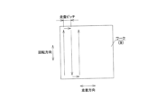
・走査ピッチ:10μm/50μm(走査ピッチは図7参照)
・走査範囲:走査ピッチ10μmでは690μm四方、走査ピッチ50μmでは650μm四方
・加工時間:30分
(結果)
結果を、図4(a)~図4(d)及び図5に示す。図4の各図の左側が加工痕全体の走査型白色干渉計による計測結果であり、右側が加工部分の拡大像である。50μmピッチの揺動無しでは、走査ピッチに依存する表面粗さの悪化がみられたのに対し、50μmピッチの揺動ありでは、走査ピッチに依存する表面粗さの悪化は見られず、表面粗さが改善した。10μmピッチでは、揺動の有無で表面粗さは変わりなかった。すなわち走査ピッチに依存する表面粗さの悪化はみられず、これ以上の表面粗さの改善もなかった。
(Processing conditions)
・Workpiece material: Quartz glass ・Polishing liquid: Slurry made by mixing acrylic particles with an average particle size of 10 μm with pure water at 10 wt% ・Material of the rotating body of the rotating tool: Fluorine rubber ・Outer diameter of the rotating body of the rotating tool: 3 mm
Rotary tool penetration depth: 400 μm
Rotational speed of the rotating tool: 2000 rpm
Workpiece oscillation: no oscillation/oscillation (
Scanning pitch: 10 μm/50 μm (see FIG. 7 for scanning pitch)
・Scanning range: 690 μm square at scanning pitch of 10 μm, 650 μm square at scanning pitch of 50 μm ・Processing time: 30 minutes (Results)
The results are shown in Figures 4(a) to 4(d) and 5. The left side of each figure in Figure 4 shows the measurement results of the entire processing mark using a scanning white light interferometer, and the right side shows an enlarged image of the processed part. Without oscillation at a 50 μm pitch, a deterioration in surface roughness dependent on the scanning pitch was observed, whereas with oscillation at a 50 μm pitch, no deterioration in surface roughness dependent on the scanning pitch was observed and the surface roughness improved. At a 10 μm pitch, the surface roughness did not change with or without oscillation. In other words, no deterioration in surface roughness dependent on the scanning pitch was observed and there was no further improvement in the surface roughness.
図5は揺動方向の表面粗さのPSD(パワースペクトル密度)の比較を示す。50μmピッチの低い空間周波数では表面粗さの改善がみられるが、10μmピッチの高い周波数領域では揺動による表面粗さの改善がみられない結果が得られた。 Figure 5 shows a comparison of the PSD (power spectral density) of surface roughness in the oscillation direction. Improvement in surface roughness was observed at a low spatial frequency of 50 μm pitch, but no improvement in surface roughness due to oscillation was observed in the high frequency region of 10 μm pitch.
この結果から推測するに、揺動の平均速度が回転ツールの回転速度と比較して1.7%程度しかなく、粒子一つ一つの流れは揺動の影響をほとんど受けないことから、走査ピッチを細かくしてスポット加工時の縞の影響がそもそも出ない状況下では、搖動を加えても更なる表面粗さの向上は図れなかったのであろう。これに対し、走査ピッチを上げた場合の表面粗さの悪化については、搖動により効果的に防止できることがわかる。 It can be inferred from these results that since the average oscillation speed is only about 1.7% of the rotational speed of the rotating tool and the flow of each particle is hardly affected by the oscillation, in a situation where the scanning pitch is made fine and the effects of stripes during spot processing do not occur in the first place, adding oscillation would not have resulted in further improvement in surface roughness. In contrast, it can be seen that the deterioration of surface roughness that occurs when the scanning pitch is increased can be effectively prevented by oscillation.
1 修正研磨加工装置
2 回転ツール
3 加工液供給手段
4 ワーク保持機構
5 揺動手段
8 研磨加工液
9 ワーク
20 回転体
21 軸体
22 回転支持部
30 噴出ノズル
31 回収槽
35 スラリー循環ポンプ
35 ポンプ
40 保持体
42 Z軸ステージ
41 X軸ステージ
43 Y軸ステージ
51 ガイド機構
52 振動アクチュエータ
70 錘
71 荷重測定装置
60 支持台
90 被加工面
REFERENCE SIGNS LIST 1
Claims (6)
前記ワークを圧電アクチュエータにより振幅1μm以上30μm以下で揺動させながら加工を行うことを特徴とする、修正研磨加工方法。 A correction polishing method in which a rotary tool capable of locally polishing is scanned and processed under numerical control while a slurry-like polishing liquid is supplied between the rotary tool and a workpiece,
A correction polishing method, characterized in that processing is performed while the workpiece is oscillated by a piezoelectric actuator with an amplitude of 1 μm to 30 μm.
該回転ツールとワークとの間に、スラリー状の研磨加工液を供給する加工液供給手段と、
前記ワークをXYZ方向に移動可能に保持するワーク保持機構と、
該ワーク保持機構に保持されたワークを圧電アクチュエータにより振幅1μm以上30μm以下で揺動させる揺動手段とを備え、
前記揺動手段によって揺動するワークに対し、前記ワーク保持機構を数値制御して走査加工する、修正研磨加工装置。 a rotating tool for polishing a workpiece, capable of polishing the workpiece locally in a stationary state without being scanned;
a processing fluid supplying means for supplying a slurry-like polishing fluid between the rotating tool and the workpiece;
a workpiece holding mechanism that holds the workpiece movably in X, Y and Z directions;
a swinging means for swinging the work held by the work holding mechanism with an amplitude of 1 μm or more and 30 μm or less by a piezoelectric actuator,
A correction polishing device in which the workpiece holding mechanism is numerically controlled to perform scanning processing on the workpiece oscillated by the oscillating means.
前記ワークを保持する保持体を、前記揺動方向に沿って案内するガイド機構と、
前記保持体を前記揺動方向に沿って振動させる振動アクチュエータと、
よりなる請求項5記載の修正研磨加工装置。 The rocking means is
a guide mechanism that guides a holder that holds the workpiece along the swing direction;
a vibration actuator that vibrates the holder along the swing direction;
6. The correction polishing apparatus according to claim 5 , further comprising:
Priority Applications (1)
| Application Number | Priority Date | Filing Date | Title |
|---|---|---|---|
| JP2020034252A JP7557166B2 (en) | 2020-02-28 | 2020-02-28 | Corrective polishing method and corrective polishing device |
Applications Claiming Priority (1)
| Application Number | Priority Date | Filing Date | Title |
|---|---|---|---|
| JP2020034252A JP7557166B2 (en) | 2020-02-28 | 2020-02-28 | Corrective polishing method and corrective polishing device |
Publications (2)
| Publication Number | Publication Date |
|---|---|
| JP2021133490A JP2021133490A (en) | 2021-09-13 |
| JP7557166B2 true JP7557166B2 (en) | 2024-09-27 |
Family
ID=77659699
Family Applications (1)
| Application Number | Title | Priority Date | Filing Date |
|---|---|---|---|
| JP2020034252A Active JP7557166B2 (en) | 2020-02-28 | 2020-02-28 | Corrective polishing method and corrective polishing device |
Country Status (1)
| Country | Link |
|---|---|
| JP (1) | JP7557166B2 (en) |
Citations (3)
| Publication number | Priority date | Publication date | Assignee | Title |
|---|---|---|---|---|
| JP2013006267A (en) | 2011-05-24 | 2013-01-10 | Canon Inc | Workpiece processing method |
| WO2016199612A1 (en) | 2015-06-12 | 2016-12-15 | 旭硝子株式会社 | Method for manufacturing glass plate, glass plate, and display device |
| JP2020025998A (en) | 2018-08-09 | 2020-02-20 | 国立大学法人 東京大学 | Local polishing method, local polishing apparatus, and modified polishing apparatus using the local polishing apparatus |
Family Cites Families (3)
| Publication number | Priority date | Publication date | Assignee | Title |
|---|---|---|---|---|
| JPS62193761A (en) * | 1986-02-17 | 1987-08-25 | Canon Inc | Polishing method |
| JPH02198758A (en) * | 1989-01-23 | 1990-08-07 | Olympus Optical Co Ltd | Processing method for optical element |
| JPH09225800A (en) * | 1996-02-22 | 1997-09-02 | Canon Inc | Polishing method |
-
2020
- 2020-02-28 JP JP2020034252A patent/JP7557166B2/en active Active
Patent Citations (3)
| Publication number | Priority date | Publication date | Assignee | Title |
|---|---|---|---|---|
| JP2013006267A (en) | 2011-05-24 | 2013-01-10 | Canon Inc | Workpiece processing method |
| WO2016199612A1 (en) | 2015-06-12 | 2016-12-15 | 旭硝子株式会社 | Method for manufacturing glass plate, glass plate, and display device |
| JP2020025998A (en) | 2018-08-09 | 2020-02-20 | 国立大学法人 東京大学 | Local polishing method, local polishing apparatus, and modified polishing apparatus using the local polishing apparatus |
Also Published As
| Publication number | Publication date |
|---|---|
| JP2021133490A (en) | 2021-09-13 |
Similar Documents
| Publication | Publication Date | Title |
|---|---|---|
| CA2234761C (en) | Deterministic magnetorheological finishing | |
| Bingham et al. | Novel automated process for aspheric surfaces | |
| EP1072357B1 (en) | Elid centerless grinding apparatus | |
| CN102794697B (en) | Method of manufacturing workpiece | |
| JP5061296B2 (en) | Flat double-side polishing method and flat double-side polishing apparatus | |
| US20210331283A1 (en) | Local polishing method, local polishing device, and corrective polishing apparatus using the local polishing device | |
| JP6617454B2 (en) | Cutting apparatus and cutting method | |
| WO2020201731A1 (en) | Shaping apparatus, method tool and composition | |
| JP7557166B2 (en) | Corrective polishing method and corrective polishing device | |
| JP2011083827A (en) | Magnetic fluid polishing method and polishing device | |
| JP4702765B2 (en) | Vibration polishing method and apparatus | |
| JP4458235B2 (en) | Concave end machining method and apparatus | |
| JP2007098541A (en) | Polishing tool and polish method | |
| JP2019166635A (en) | Cutting device and cutting method | |
| Walker et al. | Commissioning of the first Precessions 1.2 m CNC polishing machines for large optics | |
| JP2006218554A (en) | Method for creating shape of tool grinding wheel | |
| JP2005103668A (en) | Free-form surface machining method and device | |
| JP2009090414A (en) | Lens spherical grinding method | |
| JP2005111629A (en) | Polishing tool, polishing apparatus and polishing method using the same | |
| JPH11333702A (en) | Device and method for generating spherical surface | |
| JPH11170167A (en) | Polishing method and polishing apparatus for optical element | |
| JP2019155232A (en) | Cleaning method and cleaning device | |
| JP2009095973A (en) | Grinding wheel molding device and method | |
| Wu et al. | An ultra-precision polishing technique using high-velocity abrasive fluid | |
| Lin et al. | Development of X-ray mirrors manufacturing process with ELID-grinding and polishing methods |
Legal Events
| Date | Code | Title | Description |
|---|---|---|---|
| A621 | Written request for application examination |
Free format text: JAPANESE INTERMEDIATE CODE: A621 Effective date: 20221207 |
|
| A977 | Report on retrieval |
Free format text: JAPANESE INTERMEDIATE CODE: A971007 Effective date: 20230929 |
|
| A131 | Notification of reasons for refusal |
Free format text: JAPANESE INTERMEDIATE CODE: A131 Effective date: 20231003 |
|
| A601 | Written request for extension of time |
Free format text: JAPANESE INTERMEDIATE CODE: A601 Effective date: 20231204 |
|
| A521 | Request for written amendment filed |
Free format text: JAPANESE INTERMEDIATE CODE: A523 Effective date: 20240123 |
|
| A131 | Notification of reasons for refusal |
Free format text: JAPANESE INTERMEDIATE CODE: A131 Effective date: 20240416 |
|
| A521 | Request for written amendment filed |
Free format text: JAPANESE INTERMEDIATE CODE: A523 Effective date: 20240517 |
|
| TRDD | Decision of grant or rejection written | ||
| A01 | Written decision to grant a patent or to grant a registration (utility model) |
Free format text: JAPANESE INTERMEDIATE CODE: A01 Effective date: 20240730 |
|
| A61 | First payment of annual fees (during grant procedure) |
Free format text: JAPANESE INTERMEDIATE CODE: A61 Effective date: 20240827 |
|
| R150 | Certificate of patent or registration of utility model |
Ref document number: 7557166 Country of ref document: JP Free format text: JAPANESE INTERMEDIATE CODE: R150 |