JP7214729B2 - Sample container for optical measurement - Google Patents
Sample container for optical measurement Download PDFInfo
- Publication number
- JP7214729B2 JP7214729B2 JP2020526176A JP2020526176A JP7214729B2 JP 7214729 B2 JP7214729 B2 JP 7214729B2 JP 2020526176 A JP2020526176 A JP 2020526176A JP 2020526176 A JP2020526176 A JP 2020526176A JP 7214729 B2 JP7214729 B2 JP 7214729B2
- Authority
- JP
- Japan
- Prior art keywords
- sample container
- sample
- optical measurement
- area
- optical
- Prior art date
- Legal status (The legal status is an assumption and is not a legal conclusion. Google has not performed a legal analysis and makes no representation as to the accuracy of the status listed.)
- Active
Links
Images


Classifications
-
- G—PHYSICS
- G02—OPTICS
- G02B—OPTICAL ELEMENTS, SYSTEMS OR APPARATUS
- G02B21/00—Microscopes
- G02B21/0004—Microscopes specially adapted for specific applications
- G02B21/002—Scanning microscopes
- G02B21/0024—Confocal scanning microscopes (CSOMs) or confocal "macroscopes"; Accessories which are not restricted to use with CSOMs, e.g. sample holders
- G02B21/0052—Optical details of the image generation
- G02B21/0076—Optical details of the image generation arrangements using fluorescence or luminescence
-
- B—PERFORMING OPERATIONS; TRANSPORTING
- B01—PHYSICAL OR CHEMICAL PROCESSES OR APPARATUS IN GENERAL
- B01L—CHEMICAL OR PHYSICAL LABORATORY APPARATUS FOR GENERAL USE
- B01L3/00—Containers or dishes for laboratory use, e.g. laboratory glassware; Droppers
- B01L3/50—Containers for the purpose of retaining a material to be analysed, e.g. test tubes
- B01L3/502—Containers for the purpose of retaining a material to be analysed, e.g. test tubes with fluid transport, e.g. in multi-compartment structures
- B01L3/5027—Containers for the purpose of retaining a material to be analysed, e.g. test tubes with fluid transport, e.g. in multi-compartment structures by integrated microfluidic structures, i.e. dimensions of channels and chambers are such that surface tension forces are important, e.g. lab-on-a-chip
-
- G—PHYSICS
- G01—MEASURING; TESTING
- G01N—INVESTIGATING OR ANALYSING MATERIALS BY DETERMINING THEIR CHEMICAL OR PHYSICAL PROPERTIES
- G01N21/00—Investigating or analysing materials by the use of optical means, i.e. using sub-millimetre waves, infrared, visible or ultraviolet light
- G01N21/01—Arrangements or apparatus for facilitating the optical investigation
- G01N21/03—Cuvette constructions
-
- G—PHYSICS
- G01—MEASURING; TESTING
- G01N—INVESTIGATING OR ANALYSING MATERIALS BY DETERMINING THEIR CHEMICAL OR PHYSICAL PROPERTIES
- G01N21/00—Investigating or analysing materials by the use of optical means, i.e. using sub-millimetre waves, infrared, visible or ultraviolet light
- G01N21/62—Systems in which the material investigated is excited whereby it emits light or causes a change in wavelength of the incident light
- G01N21/63—Systems in which the material investigated is excited whereby it emits light or causes a change in wavelength of the incident light optically excited
- G01N21/64—Fluorescence; Phosphorescence
- G01N21/645—Specially adapted constructive features of fluorimeters
- G01N21/6456—Spatial resolved fluorescence measurements; Imaging
-
- G—PHYSICS
- G02—OPTICS
- G02B—OPTICAL ELEMENTS, SYSTEMS OR APPARATUS
- G02B21/00—Microscopes
- G02B21/36—Microscopes arranged for photographic purposes or projection purposes or digital imaging or video purposes including associated control and data processing arrangements
-
- B—PERFORMING OPERATIONS; TRANSPORTING
- B01—PHYSICAL OR CHEMICAL PROCESSES OR APPARATUS IN GENERAL
- B01L—CHEMICAL OR PHYSICAL LABORATORY APPARATUS FOR GENERAL USE
- B01L2200/00—Solutions for specific problems relating to chemical or physical laboratory apparatus
- B01L2200/06—Fluid handling related problems
- B01L2200/0689—Sealing
-
- B—PERFORMING OPERATIONS; TRANSPORTING
- B01—PHYSICAL OR CHEMICAL PROCESSES OR APPARATUS IN GENERAL
- B01L—CHEMICAL OR PHYSICAL LABORATORY APPARATUS FOR GENERAL USE
- B01L2300/00—Additional constructional details
- B01L2300/08—Geometry, shape and general structure
- B01L2300/0809—Geometry, shape and general structure rectangular shaped
- B01L2300/0822—Slides
-
- B—PERFORMING OPERATIONS; TRANSPORTING
- B01—PHYSICAL OR CHEMICAL PROCESSES OR APPARATUS IN GENERAL
- B01L—CHEMICAL OR PHYSICAL LABORATORY APPARATUS FOR GENERAL USE
- B01L2300/00—Additional constructional details
- B01L2300/08—Geometry, shape and general structure
- B01L2300/0861—Configuration of multiple channels and/or chambers in a single devices
- B01L2300/0877—Flow chambers
-
- B—PERFORMING OPERATIONS; TRANSPORTING
- B01—PHYSICAL OR CHEMICAL PROCESSES OR APPARATUS IN GENERAL
- B01L—CHEMICAL OR PHYSICAL LABORATORY APPARATUS FOR GENERAL USE
- B01L2300/00—Additional constructional details
- B01L2300/08—Geometry, shape and general structure
- B01L2300/0887—Laminated structure
-
- B—PERFORMING OPERATIONS; TRANSPORTING
- B01—PHYSICAL OR CHEMICAL PROCESSES OR APPARATUS IN GENERAL
- B01L—CHEMICAL OR PHYSICAL LABORATORY APPARATUS FOR GENERAL USE
- B01L9/00—Supporting devices; Holding devices
- B01L9/52—Supports specially adapted for flat sample carriers, e.g. for plates, slides, chips
-
- G—PHYSICS
- G01—MEASURING; TESTING
- G01N—INVESTIGATING OR ANALYSING MATERIALS BY DETERMINING THEIR CHEMICAL OR PHYSICAL PROPERTIES
- G01N21/00—Investigating or analysing materials by the use of optical means, i.e. using sub-millimetre waves, infrared, visible or ultraviolet light
- G01N21/01—Arrangements or apparatus for facilitating the optical investigation
- G01N21/03—Cuvette constructions
- G01N2021/0321—One time use cells, e.g. integrally moulded
-
- G—PHYSICS
- G01—MEASURING; TESTING
- G01N—INVESTIGATING OR ANALYSING MATERIALS BY DETERMINING THEIR CHEMICAL OR PHYSICAL PROPERTIES
- G01N21/00—Investigating or analysing materials by the use of optical means, i.e. using sub-millimetre waves, infrared, visible or ultraviolet light
- G01N21/62—Systems in which the material investigated is excited whereby it emits light or causes a change in wavelength of the incident light
- G01N21/63—Systems in which the material investigated is excited whereby it emits light or causes a change in wavelength of the incident light optically excited
- G01N21/64—Fluorescence; Phosphorescence
- G01N21/645—Specially adapted constructive features of fluorimeters
- G01N2021/6482—Sample cells, cuvettes
Description
関連出願の相互参照
本出願は、「Sample carrier for optical measurements」と題する、Yorav-raphaelによる2017年11月14日付出願の米国仮特許出願第62/585,621号に基づく優先権を主張する。
CROSS-REFERENCE TO RELATED APPLICATIONS This application claims priority to U.S. Provisional Patent Application No. 62/585,621, filed November 14, 2017, by Yorav-raphael, entitled "Sample carrier for optical measurements."
上記参照出願は、参照することにより本明細書に組み込まれる。 The above referenced applications are incorporated herein by reference.
発明の具体的態様の分野
ここに開示する主題のいくつかの応用は、一般的には光学測定に使用される試料収容器に関し、特に、身体由来の試料に対して行われる顕微鏡測定に使用される試料収容器に関する。
FIELD OF ILLUSTRATIVE EMBODIMENTS OF THE INVENTION Several applications of the presently disclosed subject matter relate to sample containers generally used for optical measurements, and particularly for microscopic measurements performed on samples from the body. It relates to a sample container.
背景
いくつかの光学ベースの方法(例、診断及び/または分析方法)において、血液試料等の生体試料の特性は、光学測定を行うことにより決定される。例えば、ある成分の密度(例、単位体積当たりのその成分の数)は顕微鏡画像内のその成分を数えることにより決定され得る。同様に、ある成分の濃度及び/または密度は、試料に対して光吸収、透過率、蛍光及び/または発光の測定を行うことにより測定され得る。典型的には、試料を試料収容器内に配置して、測定を試料収容器の小室内に含まれる試料の一部に対して行う。試料収容器の小室内に含まれる試料の一部に対して行われた測定値が、その試料の特性を決定するために分析される。
BACKGROUND In some optical-based methods (eg, diagnostic and/or analytical methods), properties of a biological sample, such as a blood sample, are determined by making optical measurements. For example, the density of a component (eg, number of that component per unit volume) can be determined by counting that component within a microscope image. Similarly, the concentration and/or density of a component can be measured by performing light absorption, transmittance, fluorescence and/or luminescence measurements on a sample. Typically, a sample is placed in a sample container and measurements are made on a portion of the sample contained within the sample container chamber. Measurements made on a portion of the sample contained within the sample container chamber are analyzed to determine characteristics of the sample.
いくつかの応用では、診断テストは、対象から採取した身体由来の試料で満たした試料収容器について行われる。そのような場合、ユーザーがカートリッジを(例えば、その洗浄後に)再使用しようとするリスクがある。これはさらに、一旦使用された試料収容器にその後配置される試料の診断において、例えば、試料収容器の先の使用からの交叉汚染(クロスコンタミネーション)及び/または残留物に起因する、誤った結果を得るリスクにつながり得る。 In some applications, diagnostic tests are performed on a sample container filled with a bodily sample taken from a subject. In such cases there is a risk that the user will try to reuse the cartridge (eg after washing it). This further leads to erroneous diagnosis of samples subsequently placed in sample containers once used, e.g., due to cross-contamination and/or residues from previous uses of the sample container. Can lead to risk of getting results.
具体的態様の概要
本発明のいくつかの応用では、試料収容器は、身体由来の試料を収納するように構成されており、該試料収容器の少なくとも一部が、少なくとも一定条件下において蛍光するように構成されている。いくつかの応用では、試料収容器の一部は、該一部またはその区域が光退色を受けたかどうかを決定するために分析される。該一部またはその区域が光退色を受けたとの検出に応答して、試料収容器またはその一部(例、その小室)が既に使用されたこと、及び/または試料収容器またはその一部(例、その小室)が使用された回数が決定される。いくつかの応用では、上記のステップは、コンピュータプロセッサによって行われる。いくつかの応用では、試料収容器またはその一部(例、その小室)が既に使用された、または、試料収容器またはその一部(例、その小室)の使用が所定の閾値を超えたとの検出に応答して、コンピュータプロセッサが、(a)試料収容器またはその一部(例、その小室)が使用されるべきでないことを示す出力を生成し、(b)試料収容器またはその一部(例、その小室)が汚染されていることを示す出力を生成し、及び/または(c)光学測定デバイスが試料収容器またはその一部(例、その小室)に対して光学測定を行うことを妨げる。
SUMMARY OF SPECIFIC EMBODIMENTS In some applications of the present invention, a sample container is configured to contain a sample from the body, and at least a portion of the sample container fluoresces at least under certain conditions. is configured as In some applications, a portion of the sample container is analyzed to determine whether the portion or area thereof has undergone photobleaching. that the sample container or portion thereof (e.g., chamber thereof) has been used in response to detection that the portion or area thereof has undergone photobleaching; For example, the number of times the chamber has been used is determined. In some applications, the above steps are performed by a computer processor. In some applications, the sample container or portion thereof (e.g., the chamber) has already been used, or the use of the sample container or portion thereof (e.g., the chamber) has exceeded a predetermined threshold. In response to the detection, the computer processor (a) produces an output indicating that the sample container or portion thereof (e.g., chamber thereof) is not to be used, and (b) the sample container or portion thereof. (e.g., the chamber) producing an output indicating that it is contaminated; and/or (c) the optical measurement device making an optical measurement on the sample container or a portion thereof (e.g., the chamber). hinder
いくつかの応用では、試料収容器が使用されると、試料収容器の所定区域が、その区域を光退色することによって標識される。例えば、光学測定デバイスは、試料収容器が光学測定デバイス内部に配置されると、および/または光学測定デバイスが試料収容器に光学測定を行うと、試料収容器の所定区域を光退色するように構成されていてもよい。いくつかの応用では、光学測定は、試料収容器に対して光学測定を行うことによって自動的に試料収容器の所定区域を光退色するように構成されている。例えば、光学測定デバイスは、試料に対して蛍光画像化(イメージング)を行う顕微鏡システムであってもよい。いくつかの応用では、顕微鏡システムが発する励起波長が、試料を蛍光させるために、試料収容器の所定区域の光退色も行う。いくつかの応用では、所定区域の光退色に先立って、コンピュータプロセッサが、上記の技術を使用して試料収容器がまだ使用されていないことを検証する。 In some applications, when the sample container is used, predetermined areas of the sample container are labeled by photobleaching the area. For example, the optical measurement device may be configured to photobleach predetermined areas of the sample container when the sample container is placed within the optical measurement device and/or when the optical measurement device performs an optical measurement on the sample container. may be configured. In some applications, the optical measurement is configured to automatically photobleach a predetermined area of the sample container by performing an optical measurement on the sample container. For example, the optical measurement device may be a microscope system that performs fluorescence imaging on the sample. In some applications, the excitation wavelengths emitted by the microscope system also cause photobleaching of predetermined areas of the sample container in order to fluoresce the sample. In some applications, prior to photobleaching a given area, a computer processor verifies that the sample container has not yet been used using the techniques described above.
いくつかの応用では、試料収容器は、再使用されるように構成されているが、限定された回数のみである。いくつかのそのような応用では、試料収容器が使用される度ごとに、試料収容器の異なる区域がそれぞれ光退色されて、コンピュータプロセッサが試料収容器に対して光退色された区域の数及び/または位置を検出することにより何回試料収容器が使用されたかを決定できるようにする。 In some applications, the sample container is configured to be reused, but only a limited number of times. In some such applications, different areas of the sample container are each photobleached each time the sample container is used, and a computer processor determines the number and number of photobleached areas for the sample container. /or to determine how many times the sample container has been used by detecting the position;
いくつかの応用では、上述の光退色効果は、試料収容器の製造メーカーによって、肉眼では見ることのできない方法で試料収容器に関する製造情報をコードするために使用される。例えば、そのような情報は、本物であることを示す標識(模倣の試料収容器が利用されている蓋然性を低くするためのもの)、試料収容器の型式、製造日、有効期限、製造場所、試験の正確な実行に必要な日付(例えば、試料収容器または複数の試料収容器のバッチに関する較正日)を含んでいてもよい。いくつかのそのような応用では、標識は、線、図、バーコード、英数字等を含む幾何学的模様を使用して付けられる。 In some applications, the photobleaching effect described above is used by sample container manufacturers to encode manufacturing information about sample containers in a way that is not visible to the naked eye. For example, such information may include authenticity tags (to reduce the likelihood of counterfeit sample containers being used), sample container model, date of manufacture, expiration date, place of manufacture, It may also include dates required for accurate execution of the test (eg, calibration date for a sample container or batch of sample containers). In some such applications, markings are applied using geometric patterns including lines, graphics, barcodes, alphanumeric characters, and the like.
従って、本発明のいくつかの応用に従い、身体由来の試料と共に使用するための装置が提供され、該装置は、
身体由来の試料の一部を収容するように構成されている試料収容器であって、該試料収容器の少なくとも一部が、少なくとも一定条件下において蛍光するように構成されている試料収容器と、
光学測定デバイスとを含み、該光学測定デバイスは、
試料収容器内に収納される身体由来の試料の一部に対して光学測定を行うように構成され、かつ、
試料収容器の一部内の区域を蛍光させることにより、該区域を少なくとも部分的に光退色させるように構成されている。
Accordingly, in accordance with some applications of the present invention, there is provided a device for use with bodily-derived samples, the device comprising:
A sample container configured to contain a portion of a body-derived sample, wherein at least a portion of the sample container is configured to fluoresce at least under certain conditions. ,
an optical measurement device, the optical measurement device comprising:
configured to perform optical measurements on a portion of a body-derived sample contained within the sample container, and
Fluorescing an area within a portion of the sample container is configured to at least partially photobleach the area.
いくつかの応用において、装置は、光学測定ユニットをさらに含み、該光学測定ユニットは、光学測定デバイスが身体由来の試料の一部に対して光学測定を行う間、試料収容器を収納するように構成され、かつ、該光学測定デバイスは、光学測定ユニットの内部に配置されている試料収容器に応答して、試料収容器の所定区域を光退色するように構成されている。 In some applications, the apparatus further includes an optical measurement unit to house the sample container while the optical measurement device performs optical measurements on the portion of the body-derived sample. and the optical measurement device is configured to photobleach a predetermined area of a sample container disposed within the optical measurement unit in response to the sample container.
いくつかの応用において、試料収容器は、光学測定デバイスによる複数の測定に使用されるように構成され、かつ、光学測定デバイスは、試料収容器が光学測定デバイスによる測定に使用される度ごとに、試料収容器の異なる区域をそれぞれ光退色するように構成されている。 In some applications, the sample container is configured to be used for multiple measurements with the optical measurement device, and the optical measurement device is adjusted each time the sample container is used for measurements with the optical measurement device. , each configured to photobleach different areas of the sample container.
いくつかの応用において、装置は、さらに、
出力デバイスと、
光学測定デバイスに操作可能に連結されている少なくとも1つのコンピュータプロセッサとを含み、該コンピュータプロセッサは、
試料収容器の一部内の区域が光退色されたことを検出するように構成され、かつ、
それに応答して、該試料収容器の少なくとも一部が汚染されていることを示す出力デバイスの出力を生成するように構成されている。
In some applications, the device further comprises:
an output device;
and at least one computer processor operably coupled to the optical measurement device, the computer processor comprising:
configured to detect when an area within a portion of the sample container has been photobleached; and
In response, it is configured to generate an output of an output device indicating that at least a portion of the sample container is contaminated.
いくつかの応用において、コンピュータプロセッサは、
試料収容器の一部内の区域が光退色されたとの検出に基づいて、該試料収容器の少なくとも一部が所定回数を超えて使用されたと決定するように構成され、かつ、
該試料収容器の少なくとも該一部が所定回数を超えて使用されたと決定したことに応答して、出力デバイスの出力を生成するように構成されている。
In some applications, the computer processor
configured to determine that at least a portion of the sample container has been used more than a predetermined number of times based on detecting that an area within the portion of the sample container has been photobleached;
An output device is configured to generate an output in response to determining that at least the portion of the sample container has been used more than a predetermined number of times.
いくつかの応用において、装置は、さらに、
出力デバイスと、
光学測定デバイスに操作可能に連結されている少なくとも1つのコンピュータプロセッサとを含み、該コンピュータプロセッサは、
試料収容器の一部内の区域が光退色されたことを検出するように構成され、かつ、
それに応答して、試料収容器の所定の一部内に収納されている試料の少なくとも一部について光学測定を行うことができないことを示す出力デバイスの出力を生成するように構成されている。
In some applications, the device further comprises:
an output device;
and at least one computer processor operably coupled to the optical measurement device, the computer processor comprising:
configured to detect when an area within a portion of the sample container has been photobleached; and
In response, it is configured to generate an output of the output device indicating that an optical measurement cannot be performed on at least a portion of the sample contained within the predetermined portion of the sample container.
いくつかの応用において、コンピュータプロセッサは、
試料収容器の一部内の区域が光退色されたとの検出に基づいて、該試料収容器の少なくとも一部が所定回数を超えて使用されたと決定するように構成され、かつ、
該試料収容器の少なくとも該一部が所定回数を超えて使用されたと決定したことに応答して、出力デバイスの出力を生成するように構成されている。
In some applications, the computer processor
configured to determine that at least a portion of the sample container has been used more than a predetermined number of times based on detecting that an area within the portion of the sample container has been photobleached;
An output device is configured to generate an output in response to determining that at least the portion of the sample container has been used more than a predetermined number of times.
いくつかの応用において、装置は、光学測定デバイスに操作可能に連結されている少なくとも1つのコンピュータプロセッサをさらに含み、該コンピュータプロセッサは、
試料収容器の一部内の区域が光退色されたことを検出するように構成され、かつ、
それに応答して、試料収容器の所定の一部内に収納されている試料の少なくとも一部について、光学測定デバイスが光学測定を行うことを妨げるように構成されている。
In some applications, the apparatus further includes at least one computer processor operably coupled to the optical measurement device, the computer processor:
configured to detect when an area within a portion of the sample container has been photobleached; and
In response, it is configured to prevent the optical measurement device from making optical measurements on at least a portion of the sample contained within the predetermined portion of the sample container.
いくつかの応用において、コンピュータプロセッサは、
試料収容器の一部内の区域が光退色されたとの検出に基づいて、該試料収容器の少なくとも一部が所定回数を超えて使用されたと決定するように構成され、かつ、
該試料収容器の少なくとも該一部が所定回数を超えて使用されたとの決定に応答して、光学測定デバイスが光学測定を行うことを妨げるように構成されている。
In some applications, the computer processor
configured to determine that at least a portion of the sample container has been used more than a predetermined number of times based on detecting that an area within the portion of the sample container has been photobleached;
An optical measurement device is configured to prevent an optical measurement in response to determining that at least the portion of the sample container has been used more than a predetermined number of times.
いくつかの応用において、光学測定デバイスは、試料に対する光学測定を行うことによって試料収容器の所定区域を光退色させるように構成されている。 In some applications, the optical measurement device is configured to photobleach a predetermined area of the sample container by performing optical measurements on the sample.
いくつかの応用において、光学測定デバイスは、試料について光学測定を行うために試料に放射線照射するように構成され、かつ、光学測定デバイスは、試料に放射線照射することによって試料収容器の所定区域を光退色させるように構成されている。 In some applications, the optical measurement device is configured to irradiate the sample to perform optical measurements on the sample, and the optical measurement device irradiates the sample to irradiate a predetermined area of the sample container. Configured for photobleaching.
さらに、本発明のいくつかの応用に従い、身体由来の試料と共に使用するための方法が提供され、該方法は、
試料収容器内に身体由来の試料の一部を配置することを含み、該試料収容器の少なくとも一部が、少なくとも一定条件下において蛍光するように構成され、及び、
該身体由来の試料の一部は試料収容器内に収納されたままで、光学測定デバイスを使用して、試料収容器内に収納されている身体由来の試料の一部に対する光学測定を行うことを含み、及び、
試料収容器の一部内の区域を蛍光させることによって、該区域を少なくとも部分的に光退色させることを含む。
Additionally, in accordance with some applications of the present invention, methods are provided for use with bodily-derived samples, the methods comprising:
placing a portion of a bodily-derived sample within a sample container, at least a portion of the sample container being configured to fluoresce at least under certain conditions; and
While the part of the body-derived sample is held in the sample container, an optical measurement device is used to perform optical measurements on the part of the body-derived sample held in the sample container. including, and
At least partially photobleaching an area within a portion of the sample container by fluorescing the area.
さらに、本発明のいくつかの応用に従い、身体由来の試料と出力デバイスと共に使用するための装置が提供され、該装置は、
身体由来の試料を収容するように構成されている試料収容器であって、該試料収容器の少なくとも一部が、少なくとも一定条件下において蛍光するように構成されている試料収容器と、
試料収容器内に収納される身体由来の試料の一部に対して光学測定を行うように構成されている光学測定デバイスと、
光学測定デバイスに操作可能に連結されている少なくとも1つのコンピュータプロセッサとを含み、該コンピュータプロセッサは、試料収容器の一部内の区域が光退色されたとの検出に応答して、以下の群、即ち、該試料収容器の少なくとも一部が汚染されていることを示す出力デバイスの出力を生成すること、該試料収容器の所定の一部内に収納されている試料の少なくとも一部について光学測定を行うことができないことを示す出力デバイスの出力を生成すること、及び、光学測定デバイスが、試料収容器の所定の一部内に収納されている試料の少なくとも一部について光学測定を行うことを妨げることからなる群から選択される作用を行うように構成されている。
Further, according to some applications of the present invention, there is provided an apparatus for use with a bodily-derived sample and an output device, the apparatus comprising:
a sample container configured to contain a bodily-derived sample, wherein at least a portion of the sample container is configured to fluoresce at least under certain conditions;
an optical measurement device configured to perform optical measurements on a portion of a bodily-derived sample contained within the sample container;
and at least one computer processor operably coupled to the optical measurement device, the computer processor being responsive to detecting that an area within a portion of the sample container has been photobleached, the following groups: generating an output device output indicating that at least a portion of the sample container is contaminated; making an optical measurement of at least a portion of the sample contained within a predetermined portion of the sample container; and preventing the optical measurement device from making optical measurements on at least a portion of the sample contained within the predetermined portion of the sample container. configured to perform an action selected from the group of
いくつかの応用において、該コンピュータプロセッサは、
試料収容器の一部内の区域が光退色されたとの検出に基づいて、該試料収容器の少なくとも一部が所定回数を超えて使用されたと決定するように構成され、かつ、
該試料収容器の少なくとも該一部が所定回数を超えて使用されたとの決定に応答して選択された作用を行うように構成されている。
In some applications, the computer processor
configured to determine that at least a portion of the sample container has been used more than a predetermined number of times based on detecting that an area within the portion of the sample container has been photobleached;
It is configured to perform a selected action in response to determining that at least the portion of the sample container has been used more than a predetermined number of times.
さらに、本発明のいくつかの応用に従い、身体由来の試料及び出力デバイスと共に使用するための方法が提供され、該方法は、
試料収容器の内部に身体由来の試料の一部を配置することを含み、該試料収容器の少なくとも一部が、少なくとも一定条件下において蛍光するように構成されており、
試料収容器内に収納されている身体由来の試料の一部に対する光学測定を行うことを含み、及び
少なくとも1つのコンピュータプロセッサを使用して、試料収容器の一部内の区域が光退色されたとの検出に応答して、以下の群、即ち、該試料収容器の少なくとも一部が汚染されていることを示す出力デバイスの出力を生成すること、該試料収容器の所定の一部内に収納されている試料の少なくとも一部について光学測定を行うことができないことを示す出力デバイスの出力を生成すること、及び、光学測定デバイスが、試料収容器の所定の一部内に収納されている試料の少なくとも一部について光学測定を行うことを妨げることからなる群から選択される作用を行うことを含む。
Additionally, in accordance with some applications of the present invention, methods are provided for use with bodily-derived samples and output devices, the methods comprising:
placing a portion of a bodily-derived sample within a sample container, wherein at least a portion of the sample container is configured to fluoresce at least under certain conditions;
comprising taking an optical measurement on a portion of the body-derived sample contained within the sample container; and using at least one computer processor to determine that an area within the portion of the sample container has been photobleached. In response to detection, producing an output of an output device indicating that at least a portion of said sample container is contaminated; generating an output of an output device indicating that an optical measurement cannot be performed on at least a portion of the sample containing the optical measurement device; and performing an action selected from the group consisting of preventing optical measurements from being made on the part.
さらに、本発明のいくつかの応用に従い、身体由来の試料及び画像化モジュールを有する顕微鏡と共に使用するための装置が提供され、該装置は、
内部に身体由来の試料の一部を収納するように構成された、少なくとも1つの小室を含み、該小室は、上側内表面と下側内表面とを含むものであって、
該上側内表面が第1の標識を含み、かつ、該下側内表面が第2の標識を含むことを特徴とし、及び、
コンピュータプロセッサを含み、該コンピュータプロセッサは、
画像化モジュールを第1の標識に焦点を合わせて、画像化モジュールと第1の標識との間の第1の焦点合わせ距離の表示を登録するように構成され、
画像化モジュールを第2の標識に焦点を合わせて、画像化モジュールと第2の標識との間の第2の焦点合わせ距離の表示を登録するように構成され、かつ、
第1の焦点合わせ距離と第2の焦点合わせ距離との差に基づいて、小室の高さを決定するように構成されている。
Further, in accordance with some applications of the present invention, there is provided an apparatus for use with a microscope having a body-derived sample and an imaging module, the apparatus comprising:
at least one chamber configured to contain a portion of a bodily-derived sample therein, the chamber including an upper inner surface and a lower inner surface;
wherein the upper inner surface comprises a first label and the lower inner surface comprises a second label; and
a computer processor, the computer processor comprising:
configured to focus the imaging module on the first landmark to register an indication of a first focusing distance between the imaging module and the first landmark;
configured to focus the imaging module on the second landmark to register an indication of a second focusing distance between the imaging module and the second landmark; and
It is configured to determine the height of the chamber based on the difference between the first focusing distance and the second focusing distance.
さらに、本発明のいくつかの応用に従い、身体由来の試料及び画像化モジュールを有する顕微鏡と共に使用するための方法が提供され、該方法は、
少なくとも1つの小室の内部に身体由来の試料の一部を配置させることを含むものであって、該小室は上側内表面と下側内表面とを含み、該上側内表面は第1の標識を含み、及び、該下側内表面は第2の標識を含んでおり、及び、
少なくとも1つのコンピュータプロセッサを使用することを含み、該コンピュータプロセッサは、
画像化モジュールを第1の標識に焦点を合わせて、画像化モジュールと第1の標識との間の第1の焦点合わせ距離の表示を登録し、
画像化モジュールを第2の標識に焦点を合わせて、画像化モジュールと第2の標識との間の第2の焦点合わせ距離表示を登録し、及び、
第1の焦点合わせ距離と第2の焦点合わせ距離との差に基づいて、小室の高さを決定する。
Further, in accordance with some applications of the present invention, methods are provided for use with a body-derived sample and a microscope having an imaging module, the method comprising:
placing a portion of the body-derived sample within at least one chamber, the chamber including an upper inner surface and a lower inner surface, the upper inner surface bearing a first label; and the lower inner surface includes a second mark, and
comprising using at least one computer processor, the computer processor comprising:
focusing the imaging module on the first landmark to register an indication of a first focusing distance between the imaging module and the first landmark;
focusing the imaging module on the second landmark to register a second focusing distance indication between the imaging module and the second landmark; and
A height of the chamber is determined based on the difference between the first focusing distance and the second focusing distance.
本発明は、以下の図面と共に示すその具体的態様の詳細な説明から、より十分に理解されるであろう。 The invention will be more fully understood from the detailed description of specific embodiments thereof taken in conjunction with the following drawings.
図面の簡単な説明Brief description of the drawing
具体的態様の詳細な説明
以下、本発明のいくつかの応用に従う生体試料分析システム20の構成要素を示すブロック図である、図1を参照する。典型的には、生体試料(例、血液試料)は、試料収容器22内に配置される。試料が試料収容器内に置かれている間、試料に対する光学測定が1以上の光学測定デバイス24を使用して行われる。例えば、光学測定デバイスは、顕微鏡(例、デジタル顕微鏡)、分光光度計、光度計、分光計、カメラ、スペクトルカメラ、ハイパースペクトルカメラ、蛍光光度計、分光蛍光光度計及び/または光検出器(例えば、光ダイオード、光レジスタ及び/または光トランジスタ)を含んでいてもよい。いくつかの応用では、光学測定デバイスは、専用の光源(例えば、発光ダイオード、白熱光源等)及び/または集光及び/または発光を操るための光学素子(レンズ、ディフューザー、フィルタ等)を含む。いくつかの応用では、参照することにより本明細書に組み込まれる、Greenfieldによる米国特許公開公報第2014/0347459号に記載されるものと概ね同様の顕微鏡システムが使用される。
DETAILED DESCRIPTION OF SPECIFIC EMBODIMENTS Reference is now made to FIG. 1, which is a block diagram illustrating components of a biological
コンピュータプロセッサ28は、典型的には、光学測定デバイスが行った光学測定を受け取って処理する。さらに典型的には、コンピュータプロセッサは、1以上の光学測定デバイスが行った光学測定の取得を制御する。コンピュータプロセッサは、メモリ30と情報交換する。ユーザー(例、ラボの技術者)は、コンピュータプロセッサにユーザーインターフェース32経由で指令を送る。いくつかの応用では、ユーザーインターフェースは、キーボード、マウス、ジョイスティック、タッチスクリーン装置(スマートフォンやタブレット型コンピュータ等)、タッチパッド、トラックボール、音声指令インターフェース及び/または本技術分野で知られているその他のタイプのユーザーインターフェースを含む。典型的には、コンピュータプロセッサは、出力デバイス34経由で出力を生成する。さらに典型的には、出力デバイスは、モニタ等のディスプレイを含み、出力は、ディスプレイ上に表示される出力を含む。いくつかの応用では、プロセッサは、例えば、スピーカー、ヘッドフォン、スマートフォンまたはタブレット型コンピュータ等の異なるタイプの視覚、文字、図形、触覚、聴覚、及び/またはビデオの出力デバイスの出力を生成する。いくつかの応用では、ユーザーインターフェース32は、入力インターフェース及び出力インターフェースの両方の役割(即ち、出入力インターフェースとしての役割)を果たす。いくつかの応用では、プロセッサは、ディスクや携帯USBドライブ等のコンピュータ読取り可能な媒体(例、コンピュータ読取り可能な非一時的な媒体)に出力を生成し、及び/またはプリンタに出力を生成する。
いくつかの応用では、光学測定デバイス24(及び/またはコンピュータプロセッサ28及びメモリ30)は、光学測定ユニット31の内部に収納される。試料に対して光学測定を行うために、試料収容器22は、光学測定ユニットの内部に配置される。
In some applications, optical measurement device 24 (and/or
以下、本発明のいくつかの応用に従って試料収容器22を様々に示す概略図である図2A及び図2Bを参照する。図2Aは試料収容器の平面図(説明用に図2Aにおいて不透明として示す試料収容器の上部のカバー)を示し、図2Bは底面図を示す(ここでは、図2Aに示す図に対して、試料収容器が短い方の端部の周りに回転されている。)。いくつかの応用では、試料収容器22は、複数の小室36(例えば、図2Aに示す5つの小室)を含む。典型的には、小室は、試料挿入孔38経由で、血液等の身体由来の試料で満たされる。いくつかの応用では、小室は、1以上の排出孔40を規定する。排出孔は、小室内に存在する空気が小室から放出されるのを許容することによって、小室が身体由来の試料で満たされるのを容易にするように構成されている。典型的には、図示するように、排出孔は、挿入孔の長手方向に向かい側(試料収容器の試料小室に対して)に位置している。いくつかの応用では、排出孔は、このようにして、挿入孔のより近くに配置されていた場合に比べて、より効率的に空気を逃がすメカニズムを提供する。
Reference is now made to Figures 2A and 2B, which are schematic diagrams showing
本発明のいくつかの応用に従う試料収容器22の展開図である図2Cを参照する。いくつかの応用では、試料収容器は、成形部42、ガラスシート44、及びガラスシートを成形部の裏側に接着するように構成されている接着層46という、少なくとも3つの構成要素を含んでいる。説明用に、ガラスシートを不存在とした成形部と接着層を示す図2Dも参照する。成形部は、典型的には、所望の幾何学形状をした小室を提供する成形(例、射出成形による)ポリマー(例、プラスチック)製である。例えば、図示する通り、成形部は、典型的には成形されて挿入孔38、排出孔40、及び各小室の中央部を囲む溝48を規定する。溝は、典型的には、空気が排出孔に流れるのを許容することにより、及び/または身体由来の試料が小室の中央部の周りを流れるのを許容することにより、小室を身体由来の試料で満たすのを容易にする。
Refer to FIG. 2C, which is an exploded view of
上述の通り、試料が試料収容器内に配置されている間に、1以上の光学測定デバイス24を使用して試料に対して光学測定が行われる。典型的には、試料は、少なくとも光学測定デバイスにより典型的に使用される波長に対して透明なガラスの、ガラス層越しに光学測定デバイスによって見ることができる。典型的には、試料収容器は、光学測定が行われている間光学測定デバイスを収納する光学測定ユニット31に挿入されている。典型的には、光学測定ユニットは、成形層がガラス層の上方に配置され、かつ、光学測定ユニットが試料収容器のガラス層の下方に配置されて、ガラス層越しに試料に対して光学測定を行うことができるように試料収容器を収納する。試料収容器は、ガラスシートを成形部に接着することにより形成される。例えば、ガラスシートと成形部は、(例えば、熱接合、溶媒の補助による接着、超音波溶接、レーザー溶接、熱杭打ち、接着、機械的クランプ及び/または追加の基板を使って)製造または組立て中に互いに接着されてもよい。いくつかの応用では、ガラス層と成形部は、接着層46を使用して、製造または組立て中に互いに接着される。
As described above, optical measurements are made on the sample using one or more
いくつかの応用では、診断テストは、対象から採取した身体由来の試料で満たした試料収容器について行われる。そのような場合、ユーザーがカートリッジを(例えば、その洗浄後に)再使用しようとするリスクがある。これはさらに、一旦使用された試料収容器にその後配置される試料の診断において、例えば、試料収容器の先の使用からの交叉汚染(クロスコンタミネーション)及び/または残留物に起因する、誤った結果を得るリスクにつながり得る。いくつかの応用では、図2A~図2Dに示す通り、試料収容器は、複数の小室を規定し、複数の試料を1本のカートリッジの対応する小室内に配置すること、及び/または複数のタイプの診断テストを対応する小室内に配置された1つの試料の対応する一部について行うことを容易にする。そのような場合には、それぞれ異なる時点で、ユーザーが様々なテストを行えるようにするのが望ましいかもしれない。しかしさらに望ましいのは、意図的であれ偶発的であれ、同じ小室を再使用しないことである。場合によっては、試料収容器は再使用されるように構成されていてもよいが、再使用は限定された回数である。いくつかの応用では、試料収容器の再使用、試料収容器の小室の再使用及び/または所定回数を超える試料収容器の再使用を防ぐために、図3A、図3B及び図3Cを参照して以下にさらに詳細に説明する、光退色を行う装置及び技術が使用される。 In some applications, diagnostic tests are performed on a sample container filled with a bodily sample taken from a subject. In such cases there is a risk that the user will try to reuse the cartridge (eg after washing it). This further leads to erroneous diagnosis of samples subsequently placed in sample containers once used, e.g., due to cross-contamination and/or residues from previous uses of the sample container. Can lead to risk of getting results. In some applications, as shown in FIGS. 2A-2D, the sample container defines multiple compartments, allowing multiple samples to be placed in corresponding compartments of a single cartridge and/or multiple It facilitates performing types of diagnostic tests on corresponding portions of a single sample placed in corresponding chambers. In such cases, it may be desirable to allow the user to run different tests at different times. Even more desirable, however, is not to reuse the same chamber, either intentionally or accidentally. In some cases, the sample container may be configured to be reused, but only a limited number of times. In some applications, to prevent reuse of sample containers, reuse of sample container compartments, and/or reuse of sample containers beyond a predetermined number of times, see FIGS. 3A, 3B, and 3C. Equipment and techniques for photobleaching are used, which are described in more detail below.
いくつかの応用では、試料収容器22の一部は、少なくとも一定条件下において蛍光するように構成されている。例えば、試料収容器の一部は、光学測定デバイス24が発する光(例、顕微鏡システムが発する明視野光または蛍光発光)に暴露されると蛍光するように構成されていてもよい。あるいは、試料収容器の一部が、光学測定デバイス24が収納される光学測定ユニット31内に配置されると蛍光するように構成されていてもよい。上述の通り、いくつかの応用では、試料収容器22は、接着層46を含む。いくつかの応用では、接着層またはその一部は、上記の方法によって(例、蛍光するように構成されている接着層内の接着剤によって、蛍光するように構成されている追加の材料を含む接着層によって、及び/またはそのような材料で被膜されている接着層によって)蛍光するように構成されている。いくつかの応用では、接着層は、少なくとも一部が蛍光するように構成されている加圧接着剤である。例えば、加圧接着は、少なくとも一部が蛍光するように構成されているアクリル系加圧接着剤であってもよい。いくつかの応用では、蛍光するように構成されている試料収容器の一部は、さらに、蛍光励起(例えば、電磁スペクトルの紫外線部分)に暴露された区域において光退色を受けるように構成されている。例えば、そのような区域は、1分未満、10秒未満または1秒未満の蛍光励起に暴露されると光退色を受けるように構成されていてもよい。典型的には、光退色される区域は、光学測定デバイス24(例、顕微鏡システム)を使用して見ることができ、また、さらに典型的には、光退色は、少なくとも1週間、例えば、少なくとも1ヵ月間または1年間、可視の状態を維持する。
In some applications, a portion of
以下、本発明のいくつかの応用に従い、短期の蛍光励起に暴露した直後(図3A)及び暴露から1週間後(図3B)の試料収容器の顕微鏡画像上の光退色した斑紋50を示す図3A及び図3Bを参照する。図3A及び図3Bに示す斑紋の直径はおよそ2mmであり、図に示す通り、顕微鏡画像において可視である。
Below are diagrams showing
また、本発明のいくつかの応用に従い、試料収容器を短期の蛍光励起に暴露した直後(x軸沿いの200~300に最も高いピークを有する曲線)、試料収容器を短期の蛍光励起に暴露した1週間後(x軸沿いの200~300に真ん中のピークを有する曲線)及び試料収容器を短期の蛍光励起に暴露した3週間後(x軸沿いの200~300に最も低いピークを有する曲線)に、試料収容器の長さ(x軸)に沿って測定した、試料収容器からの蛍光発光のプロット(y軸)である図3Cも参照する。プロットは、最も濃い斑紋と等しい強度を有するように正規化された。 Also, in accordance with some applications of the present invention, immediately after exposing the sample container to short-term fluorescence excitation (curve with highest peak at 200-300 along the x-axis), the sample container is exposed to short-term fluorescence excitation. 1 week after exposure (curve with middle peak at 200-300 along the x-axis) and 3 weeks after exposing the sample container to short-term fluorescence excitation (curve with lowest peak at 200-300 along the x-axis) ), see also FIG. 3C, which is a plot of fluorescence emission from the sample container (y-axis) measured along the length of the sample container (x-axis). Plots were normalized to have equal intensity with the darkest mottling.
図3A~図3Cに実証される効果に従えば、本発明のいくつかの応用では、試料収容器の一部は、該一部またはその区域が光退色を受けたかどうかを決定するために分析される。光退色を受けたとの検出に応答して、試料収容器またはその一部(例、その小室)が既に使用されたこと、及び/または試料収容器またはその一部(例、その小室)が使用された回数が決定される。いくつかの応用では、上記のステップは、コンピュータプロセッサ28によって行われる。いくつかの応用では、試料収容器またはその一部(例、その小室)が既に使用された、または試料収容器またはその一部(例、その小室)の使用が所定の閾値を超えたとの検出に応答して、コンピュータプロセッサが、試料収容器またはその一部(例、その小室)が使用されるべきでないことを示す出力を生成し、試料収容器またはその一部(例、その小室)が汚染されていることを示す出力を生成し、及び/または光学測定デバイスが試料収容器またはその一部(例、その小室)に対して光学測定を行うことを妨げる。
3A-3C, in some applications of the present invention, a portion of the sample container is analyzed to determine if the portion or area thereof has undergone photobleaching. be done. that the sample container or portion thereof (e.g., chamber thereof) has been used and/or that the sample container or portion thereof (e.g., chamber thereof) has been used in response to detection that it has undergone photobleaching; is determined. In some applications, the above steps are performed by
いくつかの応用では、試料収容器の所定区域は、試料収容器が使用されている場合にその区域を光退色することによって標識される。例えば、光学測定デバイス24は、光学測定が試料の一部に対して行われる間試料収容器を収納する光学測定ユニット31の内部に試料収容器が配置された場合に、試料収容器の所定区域を光退色するように構成されていてもよい。代替的または追加的に、光学測定デバイス24は、光学測定デバイスが試料収容器について光学測定を行う場合に、試料収容器の所定区域を光退色するように構成されていてもよい。いくつかの応用では、光学測定デバイスは、試料収容器に対して光学測定を行うことによって試料収容器の所定区域を自動的に光退色するように構成されている(即ち、特に光退色を行わせるための何らかの行為であって、光学測定デバイスが光学測定を行うためにいかなる場合も行わなかったであろう行為を特に行う必要なく)。例えば、光学測定デバイスは、試料及び/または試料の染色した一部を試料及び/または試料の染色した一部の励起波長に対応する光で励起することによって試料に対して蛍光画像化を行う顕微鏡システムであってもよく、その光で試料及び/または試料の染色した一部を蛍光させるようにしてもよい。試料及び/または試料の染色した一部を蛍光させるために顕微鏡システムが発する光は、試料収容器の所定区域の光退色も行ってもよい。いくつかの応用では、所定区域の光退色に先立って、コンピュータプロセッサが、上記の技術を使用して、試料収容器がまだ使用されていないことを検証する。
In some applications, predetermined areas of the sample container are marked by photobleaching the area when the sample container is in use. For example, the
上述の通り、いくつかの応用では、試料収容器は、再使用されるように構成されているが、限定された回数のみである。いくつかのそのような応用では、試料収容器が使用される度ごとに、試料収容器の異なる区域がそれぞれ光退色されて、コンピュータプロセッサが試料収容器に対して光退色された区域の数及び/または位置を検出することにより何回試料収容器が使用されたかを決定できるようにする。 As noted above, in some applications the sample container is configured to be reused, but only a limited number of times. In some such applications, different areas of the sample container are each photobleached each time the sample container is used, and a computer processor determines the number and number of photobleached areas for the sample container. /or to determine how many times the sample container has been used by detecting the position;
いくつかの応用では、上述の光退色効果は、試料収容器の製造メーカーによって、肉眼では見ることのできない方法で試料収容器に関する製造情報をコードするために使用される。例えば、そのような情報は、本物であることを示す標識(模倣の試料収容器が利用されている蓋然性を低くするためのもの)、試料収容器の型式、製造日、有効期限、製造場所、試験の正確な実行に必要な日付(例えば、試料収容器または複数の試料収容器のバッチに関する較正日)を含んでいてもよい。いくつかのそのような応用では、標識は、線、図、バーコード、英数字等を含む幾何学的模様を使用して付けられる。 In some applications, the photobleaching effect described above is used by sample container manufacturers to encode manufacturing information about sample containers in a way that is not visible to the naked eye. For example, such information may include authenticity tags (to reduce the likelihood of counterfeit sample containers being used), sample container model, date of manufacture, expiration date, place of manufacture, It may also include dates required for accurate execution of the test (eg, calibration date for a sample container or batch of sample containers). In some such applications, markings are applied using geometric patterns including lines, graphics, barcodes, alphanumeric characters, and the like.
いくつかの応用では、所定の試料を含む試料収容器が光学測定デバイスによって複数回分析される。例えば、試料は、分析された後、一定の時間間隔で再分析されてもよい。いくつかの応用では、同一試料の複数の一部がそれぞれ個別に試料収容器の小室内に配置されて、それぞれ別個の時間間隔で分析される。いくつかの応用では、同一試料が確実に再分析されるように、光学測定デバイスが、所定の方法で、光退色を通して試料収容器を標識するように構成されている。その後、試料収容器が光学測定ユニットまたは再分析用の別の光学測定ユニットの内部に戻されると、コンピュータプロセッサが、試料収容器に付けた標識を識別することによりそれが同一試料収容器であることを検証する。 In some applications, a sample container containing a given sample is analyzed multiple times by an optical measurement device. For example, a sample may be re-analyzed at regular time intervals after being analyzed. In some applications, multiple portions of the same sample are each individually placed in a sample container chamber and analyzed at each distinct time interval. In some applications, optical measurement devices are configured to label sample containers through photobleaching in a predetermined manner to ensure that the same sample is re-analyzed. Thereafter, when the sample container is returned inside the optical measurement unit or another optical measurement unit for reanalysis, the computer processor recognizes that it is the same sample container by identifying the label attached to the sample container. verify that
上述の装置及び方法は、少なくとも一定条件下で蛍光するように構成されている試料収容器の一部を光退色させることに関わるが、試料収容器の特定の設計に限定されないことが留意される。むしろ、試料収容器の任意の設計がそのような一部を組み込むように構成されていてもよい。同様に、上述の装置及び方法は、少なくとも一定条件下で蛍光するように構成されている試料収容器の一部を光退色させることに関わるが、試料収容器の特定の一部に限定されない。むしろ、試料収容器の任意の一部がそのような特徴を有するように構成されていてもよい。例えば、本明細書中に記載した試料収容器の成形部、接着層またはガラスシートの任意の一部がこのように構成されていてもよい。 It is noted that while the apparatus and methods described above involve photobleaching at least a portion of a sample container that is configured to fluoresce under certain conditions, it is not limited to any particular design of the sample container. . Rather, any design of sample container may be configured to incorporate such a portion. Similarly, the apparatus and methods described above involve photobleaching at least a portion of a sample container that is configured to fluoresce under certain conditions, but is not limited to any particular portion of the sample container. Rather, any portion of the sample container may be configured with such features. For example, any portion of the moldings, adhesive layers or glass sheets of the sample containers described herein may be configured in this manner.
以下、本発明のいくつかの応用に従う、試料に対する顕微鏡測定と光学密度測定の両方を容易にするように構成されている試料収容器である、試料収容器22を様々に示す概略図である図4A、図4B、図4C及び図4Dを参照する。図4Aは試料収容器の平面図(説明用に、図4Aにおいて不透明として示す試料収容器の上部のカバー)を示し、図4Bは底面図(ここでは、図4Aに示す図に対して、試料収容器が長い方の端部の周りに回転されている。)を示し、図4Cは展開側面図を示す。
DETAILED DESCRIPTION OF THE INVENTION Various schematic diagrams of a
いくつかの応用では、血液試料について全血球計算(CBC)を行う時に図4A~図4Cに示す試料収容器が使用される。いくつかの応用では、試料収容器は、試料に対して顕微鏡分析を行うために使用される小室の第1のセット52と、試料に対して光学密度測定を行うために使用される小室の第2のセット54を含む。図2A~図2Dを参照して上述した通り、いくつかの応用では、試料収容器は、図4Cに示す通り、成形部42、ガラスシート44及び接着層46から作られる。いくつかの応用では、上述の通り、接着層は、蛍光する及び/または光退色されるように構成されている。典型的には、概ね上述した通り、成形部は、挿入孔38、排出孔40及び/または溝48を規定するように構成されている。
In some applications, the sample container shown in Figures 4A-4C is used when performing a complete blood count (CBC) on a blood sample. In some applications, the sample container includes a first set of
参照することにより本明細書に組み込まれるPollackによる国際公報第WO17/195205号に記載される通り、いくつかの応用では、セット54に属する小室(これは光学密度測定用に使用される)は、典型的には少なくとも第1の領域56(これは典型的にはより深い)と第2の領域58(これは典型的にはより浅い)を規定し、第1及び第2の領域の間で小室の高さはあらかじめ決定された方法により異なっている。 As described in International Publication No. WO17/195205 by Pollack, which is incorporated herein by reference, in some applications the chambers belonging to set 54, which are used for optical density measurements, are Typically defining at least a first region 56 (which is typically deeper) and a second region 58 (which is typically shallower), and between the first and second regions The chamber heights differ in a predetermined manner.
典型的には、試料に対して光学分析を行うためには、光学測定が行われた対象の試料の一部の光路長、体積及び/または厚さをできる限り正確に知ることが望ましい。さらに典型的には、光学測定は、2以上の向かい合う表面によって規定される試料収容器内に配置される試料の一部に対して行われる。所望のレベルの精度を提供するためには、2以上の向かい合う表面が、同様に厳密にセットされるまたは厳密に制御される距離によって分離されていることが望ましい。ただし、製造または組立て工程によっては、向かい合う表面間の距離に実質的な違いがあることがある。例えば、図4A~図4Cに示す小室の上側及び下側表面は、それぞれ成形部及びガラスシートによって規定され、この成形部とガラスシートとは接着層を介して互いに連結されている。接着層は名目厚さを有するが、例えば、加圧接着剤の製造厚さのばらつきまたはその適用中にかかる圧力のばらつきのために、層の実際の厚さが名目厚さと異なるのが典型的である。例えば、成形部とガラスシートとは、100マイクロメートル離れて向かい合う表面によって分離するように構成されている、名目厚さを有する加圧接着層を使って結合されていてもよい。そのような場合には、加圧接着層の製造厚さのばらつきまたはその適用中にかかる圧力のばらつきによって、例えば、名目厚さよりも20マイクロメートルほど多くまたは少なくなった最終厚さになり得る。
Typically, in order to perform optical analysis on a sample, it is desirable to know as accurately as possible the optical path length, volume and/or thickness of the portion of the sample on which the optical measurement was performed. More typically, optical measurements are made on a portion of a sample positioned within a sample container defined by two or more facing surfaces. To provide the desired level of accuracy, it is desirable that two or more opposing surfaces are separated by a similarly tightly set or tightly controlled distance. However, depending on the manufacturing or assembly process, there may be substantial differences in the distance between facing surfaces. For example, the upper and lower surfaces of the chambers shown in FIGS. 4A-4C are defined by a molding and a glass sheet, respectively, which are connected to each other via an adhesive layer. Although the adhesive layer has a nominal thickness, the actual thickness of the layer typically differs from the nominal thickness due, for example, to variations in manufacturing thickness of the pressure adhesive or variations in the pressure applied during its application. is. For example, the molding and glass sheet may be bonded using a pressure adhesive layer having a nominal thickness configured to be separated by facing
典型的には、光学測定は、試料について行われる。例えば、ある成分の密度は顕微鏡画像内のその成分を数えることにより決定され得る。同様に、ある成分の濃度及び/または密度は、試料に対して光吸収、透過率、蛍光及び/または発光の測定を行うことによって測定され得る。理論に縛られることなく、2つの向かい合う表面を分離する距離における20パーセントの不確実性(上記の例で記載した通り)は、それがまた試料に対して行われる光学測定に由来する試料のパラメータにおける20パーセントの不確実性に対応し得る(試料内のある成分の導き出された濃度及び/または密度等)が、これは例えば、参照することにより本明細書に組み込まれるPollackによる国際公報第WO17/195205号に記載される通りである。 Typically, optical measurements are made on a sample. For example, the density of a component can be determined by counting that component within the microscope image. Similarly, the concentration and/or density of a component can be measured by performing light absorption, transmittance, fluorescence and/or luminescence measurements on a sample. Without being bound by theory, the 20 percent uncertainty in the distance separating two facing surfaces (as noted in the example above) is a sample parameter derived from optical measurements that are also made on the sample. (such as the derived concentrations and/or densities of certain components in the sample), which can be accommodated, for example, in International Publication No. WO17 by Pollack, incorporated herein by reference. /195205.
本発明のいくつかの応用に従えば、試料小室の高さに関係する不確実性に伴う上述の問題は、少なくとも部分的に克服される。再び図4Aを参照すると、セット54に属する試料小室は、第1の領域56及び第2の領域58を規定する。試料小室の第1の領域56及び第2の領域58の高さは、ガラスシートによって規定される下側表面と、成形部によって規定される上側表面とによって規定される。第2の領域における上側表面は、第1の領域における上側表面に対して段差がつけられている。第1及び第2の領域の上側表面間の段差は、領域間にあらかじめ定義された高低差Δhを提供して、領域の絶対的高さが十分な正確度で分からない場合でも、本明細書に記載される技術及び参照することにより本明細書に組み込まれるPollackによる国際公報第WO17/195205号に記載される通りの技術を使用して、高低差Δhは、試料のパラメータの決定に十分な正確度で分かる。
In accordance with some applications of the present invention, the above-described problems associated with uncertainties related to sample chamber height are at least partially overcome. Referring again to FIG. 4A, the sample chambers belonging to set 54 define
上述の通り、成形部は、段差のある表面を規定する形状であり、例えば、セット54に属する小室の高さが第1及び第2の領域間で変化する方法で規定する。典型的には、単一基板内の、特に、近接する表面間の相対的製作公差は、異なる基板間、あるいは同一基板内の向かい合う表面間でも、その位置決めの製作公差と比べてより厳格である。したがって、第1及び第2の領域間での1以上の試料小室の高さの変化の仕方を単一基板に規定させることで、第1及び第2の領域間の高低差が比較的正確になるようにするのが典型的である。例えば、成形部は、射出成形、エンボス加工または機械加工(マシニング)等を使用して、比較的厳格な公差で製造されてもよい。
As mentioned above, the moldings are shaped to define a stepped surface, for example in such a way that the height of the chambers belonging to the
参照することにより本明細書に組み込まれるPollackによる国際公報第WO17/195205号に記載される通り、いくつかの応用では、セット52に属する小室(これは顕微鏡を使用する測定に使用される)は互いに高さが異なるが、これは、異なる測定対象をそれぞれ異なる小室の顕微鏡画像を使用して測定すること、及び/または異なる小室をそれぞれ異なる試料タイプの顕微鏡分析用に使用することを容易にするためである。例えば、血液試料及び/または試料により形成される単分子層の赤血球が比較的低密度な場合には、測定は、統計的に信頼できるデータを提供するために、十分な密度の細胞があるように、及び/または試料により形成される単分子層内に十分な密度の細胞があるように、高さが比較的大きい試料収容器の小室内で行われてもよい。そのような測定の例は、例えば、赤血球密度測定、細胞のその他の属性の測定(例えば、異常な赤血球の数、細胞内小体を含む赤血球(例、病原体、ハウエルジョリー小体)等)及び/またはヘモグロビン濃度を含む。逆に、血液試料及び/または試料により形成される単分子層が比較的高い赤血球密度を有するとすると、その測定は、高さの比較的低い試料収容器の小室に対して、例えば、細胞が十分に散在するように、及び/または試料により形成される細胞の単分子層内で細胞が十分に散在して顕微鏡画像内で細胞が特定できるように、行われてもよい。いくつかの応用では、そのような方法は、明確に分かっているセット52に属する小室間の高さの差がなくても行われる。 As described in International Publication No. WO17/195205 by Pollack, which is incorporated herein by reference, in some applications the chambers belonging to set 52, which are used for measurements using a microscope, are Different heights from each other, which facilitates measuring different objects using microscopic images of different chambers and/or using different chambers for microscopic analysis of different sample types. It's for. For example, if a blood sample and/or a monolayer of red blood cells formed by the sample has a relatively low density, the measurement should be performed such that there are sufficient densities of cells to provide statistically reliable data. and/or in a sample container chamber that is relatively tall such that there is a sufficient density of cells within the monolayer formed by the sample. Examples of such measurements include, e.g., red blood cell densitometry, measurement of other attributes of cells (e.g., abnormal red blood cell count, red blood cells containing intracellular bodies (e.g., pathogens, Howell-Jolly bodies), etc.) and /or include hemoglobin concentration. Conversely, if the blood sample and/or the monolayer formed by the sample has a relatively high red blood cell density, the measurement may be performed for a sample container chamber of relatively low height, e.g. It may be done so that the cells are sufficiently dispersed and/or within the monolayer of cells formed by the sample that the cells are sufficiently dispersed to be identifiable in the microscopic image. In some applications, such a method may be performed without a well-known height difference between chambers belonging to set 52 .
いくつかの応用では、測定された測定対象に基づいて、光学測定を行う対象となる試料収容器内の小室が選択される。例えば、試料収容器の比較的大きい高さの小室は、(例えば、より浅い領域において低い計測値になり得る統計学的誤差を減らすために)白血球数の計測や白血球分化を行う及び/またはより稀な形の白血球を検出するために使用されてもよい。逆に、平均赤血球ヘモグロビン(MCH)、平均赤血球体積 (MCV)、赤血球分布幅(RDW)、赤血球の形態学的特徴及び/または赤血球の異常を決定するために、高さの比較的低い試料小室の小室から顕微鏡画像を得てもよく、なぜなら、そのような小室内では、細胞は、領域の面積全体にわたって比較的分散して分布している、及び/または細胞が比較的分散した単分子層を形成しているからである。同様に、血小板を計測したり、血小板を分類したり、及び/または血小板のその他の属性(体積等)を抽出したりするために、高さの比較的低い試料小室の小室から顕微鏡画像を得てもよく、なぜなら、そのような小室内では、顕微鏡画像において及び/または単分子層において、血小板と(完全または部分的に)重なり合う赤血球がより少ないからである。 In some applications, a chamber within the sample container is selected for optical measurements based on the measured measurement target. For example, the relatively large height chamber of the sample container may be used to perform leukocyte counts and leukocyte differentiation and/or to reduce statistical errors that can result in lower counts in shallower regions, for example. It may be used to detect rare forms of white blood cells. Conversely, to determine mean corpuscular hemoglobin (MCH), mean corpuscular volume (MCV), erythrocyte distribution width (RDW), erythrocyte morphological characteristics and/or erythrocyte abnormalities, sample chambers of relatively low height A microscopic image may be obtained from a chamber of a cell because, within such a chamber, the cells are distributed relatively diffusely over the area of the region and/or the cells form a relatively dispersed monolayer. This is because it forms Similarly, a microscopic image may be obtained from a relatively low-height sample chamber to count platelets, classify platelets, and/or extract other attributes of platelets (such as volume). because within such chambers fewer red blood cells overlap (completely or partially) with platelets in the microscopic image and/or in the monolayer.
上述の例に従えば、試料(血液試料等)内のある測定対象の測定のために光学測定を行うには、試料収容器のより低い小室を使用するのが好ましい一方、そのような試料内の他の測定対象の測定のために光学測定を行うには、試料収容器のより高い小室を使用するのが好ましい。したがって、いくつかの応用では、試料収容器のセット52に属する第1の小室内に配置される試料の一部に対して(例えば、その顕微鏡画像を取得して)、第1の光学測定を行うことによって試料内の第1の測定対象が測定され、また、試料収容器のセット52の第2の小室内に配置される試料の一部に対して(例えば、その顕微鏡画像を取得して)、第2の光学測定を行うことによって同一試料の第2の測定対象が測定される。いくつかの応用では、第1及び第2の測定対象は、例えば、参照することにより本明細書に組み込まれるZaitによる国際公報第WO17/195208号に記載される通りの技術を使用して、互いに対して正規化される。 Following the example above, while it is preferable to use the lower chamber of the sample container to perform optical measurements for the measurement of certain objects within a sample (such as a blood sample), It is preferable to use the higher chamber of the sample container for performing optical measurements for the measurement of other objects to be measured. Therefore, in some applications, a first optical measurement is performed on a portion of a sample located within a first chamber belonging to the set of sample receptacles 52 (e.g., acquiring a microscopic image thereof). A first measurement object in the sample is measured by performing a measurement on a portion of the sample placed in the second chamber of the set of sample containers 52 (for example, acquiring a microscopic image thereof). ), a second target of the same sample is measured by performing a second optical measurement. In some applications, the first and second measurands are combined with each other, for example, using techniques as described in International Publication No. WO17/195208 to Zait, incorporated herein by reference. normalized to
以下、本発明のいくつかの応用に従う、顕微鏡測定と光学密度測定の両方を行うのに使用するために構成されている試料収容器である、試料収容器22を様々に示す概略図である図5A、図5B及び図5Cを参照する。図5Aは試料収容器の底面図を示し、底部表面を透明にして、試料収容器の小室の特徴が観察できるようにしている。図5B及び5Cは、試料収容器の最上層が不透明である、試料収容器の平面図を示す(そして、ここでは、図5Aに示す図に対して、試料収容器が長い方の端部の周りに回転されている。)。
Below are various schematic diagrams of a
図5A、図5B及び図5Cに示す試料収容器は、下記に説明する違いを除き、図4A~図4Cに示し同図面を参照して説明したものと概ね同様である。いくつかの応用では、試料収容器は、試料に対して顕微鏡分析を行う際に使用される小室の第1のセット52と、試料に対して光学密度測定を行う際に使用される小室の第2のセット54を含む。いくつかの応用では、試料に対して光学密度測定を行う際に使用される小室の第2のセットは、図に示す通り、小室を1つだけ含む。いくつかの応用では、試料に対して顕微鏡分析を行う際に使用される小室の第1のセット52内に複数の小室があり、各々の小室が排出孔40を規定する(これは概ね上述の通り)。いくつかのそのような応用では、小室の第1のセットに属する各小室の排出孔は互いにごく近接して配置され(図5Bに示す通り)て、例えば、これらの孔が1cmの長さよりも短い直線沿いに配置されるようにする。例えば、各小室からその排出孔に延びるそれぞれのチャネル51があってもよく、これにより排出孔が互いにごく近接して配置されるようにする。
The sample container shown in Figures 5A, 5B and 5C is generally similar to that shown and described with reference to Figures 4A-4C, except for the differences described below. In some applications, the sample container includes a first set of
いくつかの応用では、カバー60(図5Cに示す)が、カバーが排出孔を覆う等のために反転可能に(または選択的に、反転不可能に)試料収容器に連結されている。例えば、カバーは、接着性の裏材を有する紙、スポンジまたはフィルタ素材を含んでいてもよい。典型的には、カバーは、試料が試料収容器から漏出するのを防ぐように構成されて、試料収容器からの漏出による光学測定デバイスの汚染を起こりにくくする。いくつかの応用では、カバーは、小室から出る空気流の速度を制限することによって、小室の第1のセット52を充填する速度を制御するように構成されている。いくつかの応用では(図示せず)、カバー60と概ね同様のカバーが、小室の第2のセット54に付随する排出孔を覆って配置される。
In some applications, a cover 60 (shown in FIG. 5C) is reversibly (or optionally, non-reversible) connected to the sample container such that the cover covers the drain hole or the like. For example, the cover may comprise paper, sponge or filter material with an adhesive backing. Typically, the cover is configured to prevent sample from leaking out of the sample container, making contamination of the optical measurement device by leakage from the sample container less likely. In some applications, the cover is configured to control the rate of filling the
いくつかの応用では、試料収容器22は、入口孔38に隣接する貯蔵室39を規定する形状である。典型的には、貯蔵室は、ユーザーが試料収容器の小室に身体由来の試料を充填できるように構成され、これにより、一方では、ユーザーが正確な体積の身体由来の試料を入口孔に挿入することを要求されず、他方では、入口孔は実質的に液体がない状態のままになる。
In some applications,
以下、本発明のいくつかの応用に従う、試料収容器の小室が下側内表面上の第1の標識62(即ち、ガラス層の内表面)と上側内表面上の第2の標識64(例、基板層の内表面)とを含む、試料収容器22の底面を示す概略図である図6を参照する。図6に示す図において、基板層の内表面は、透明ガラス層越しに見えている。対応する応用に従えば、標識は、線またはその他の形状(例、英数字)を構成していてもよい。標識は、試料収容器に印刷されていてもよく、試料収容器に描かれていてもよく、試料収容器にエッチングされていてもよく、試料収容器に彫り込まれていてもよく、試料収容器に接着されていてもよく、試料収容器内に埋設されていてもよく、試料収容器及び/または試料収容器のその他の可視的な特徴内の出っ張り及び/または窪みを構成していてもよく及び/または試料収容器に取り付けられていてもよい。
Hereinafter, according to some applications of the present invention, the sample container chamber has a
典型的には、試料は、上側及び下側表面によって規定される高さを有する体積を満たす。例えば、1小室内の試料の一部の体積は、小室の面積に小室の高さを乗ずることによって規定される。ただし、場合により、例えば上述の理由のために、正確な小室の高さが分からないことがある。いくつかの応用では、コンピュータプロセッサは、光学測定デバイスの画像化モジュールを第1の標識62に焦点を合わせて第1の標識に関連する焦点合わせ距離F1の表示を登録することで小室の高さを決定する。コンピュータプロセッサは、また、光学測定デバイスの画像化モジュールを第2の標識64にも焦点を合わせて、第2の標識に関連する焦点合わせ距離F2の表示を登録する。コンピュータプロセッサは、次いで、F1とF2の差に基づいて、小室の高さを決定する。いくつかの応用では、コンピュータプロセッサは、決定された小室の高さに基づいて、小室の体積またはその一部を決定する。典型的には、コンピュータプロセッサは、少なくとも部分的に、決定された小室の高さに基づいて、例えば、上述の技術を使用して、試料の特性を決定する。
Typically, the sample fills a volume having a height defined by upper and lower surfaces. For example, the partial volume of a sample in one chamber is defined by the area of the chamber multiplied by the height of the chamber. However, in some cases the exact chamber height may not be known, for example for the reasons mentioned above. In some applications, the computer processor focuses the imaging module of the optical measurement device on the
典型的には、光学測定デバイス24の画像化モジュールに対する試料収容器の位置決めには、ある程度のばらつきがある。例えば、顕微鏡ステージ上の試料収容器の配置は、要求される画像解像度に照らして有意に異なり得る(例えば、顕微鏡の限界、試料収容器におけるばらつき、装置のオペレータが配置する際におけるばらつき等に起因して)。したがって、いくつかの応用に従えば、光学測定デバイス24の画像化モジュールに対する試料収容器の位置決めは、本明細書中に記載の技術に従って決定される。
Typically, there is some variability in the positioning of the sample container with respect to the imaging module of
いくつかの応用では、光学測定デバイスの画像化モジュールと、試料収容器が配置されるステージの初期の位置は、試料収容器上の可視標識が画像化モジュールの観察フィールド内に現れるように決められる。これに続いて、試料収容器の位置及び/または配向の少なくともXY平面に対する規定に十分な情報を入手するまで、試料収容器の表面部分がスキャンされる(本願においては、光学システムの光軸を指す用語としてZ軸を使用し、また、XY平面は、本技術分野で慣用されるように、光軸に垂直な平面を示す用語として使用される。)。 In some applications, the initial positions of the imaging module of the optical measurement device and the stage on which the sample container is placed are determined such that the visible markings on the sample container appear within the viewing field of the imaging module. . Following this, a portion of the surface of the sample container is scanned (in this application, the optical axis of the optical system is The Z-axis is used as a term to refer to, and the XY plane is used as a term to indicate a plane perpendicular to the optical axis, as commonly used in this technical field.).
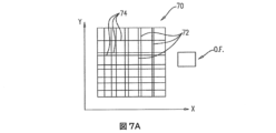
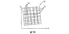
以下、本発明のいくつかの応用に従う、正方形の境界線76内に限定された、垂直方向の線72と水平方向の線74のセットを含むパターンである、不規則パターン70の例を示す図7A及び図7Bを参照する。図7Bは、図7Aに示す不規則パターンを図7Aに示すものに対して傾けた配向で示す図である。いくつかの応用では、図7A~図7Bに示すもの等の不規則パターンは試料収容器22上に標識されている。光学測定デバイスは、典型的には顕微鏡システムを含み、観察フィールドを通して試料収容器を画像化する。典型的には、そのような観察フィールドは、試料収容器の小室内の小区分を画像化する。
Below is a diagram illustrating an example of an
垂直方向の線72の間の間隔が不規則である、即ち、隣接する2本の垂直方向の線72の間の距離は、それぞれ任意の他の隣接する2本の垂直方向の線72の間の距離と異なっていることが観察され得る。同一の設計は水平方向の線にも適用される。例示として、不規則パターンは、約2.7×2.7mm2の寸法であり得るが、観察フィールドは約0.6×0.8mm2の寸法であり得る。
The spacing between
不規則パターン70と観察フィールドは本質的に長方形ないし正方形のものとして示されているが、任意の他の形状も使用し得ることが留意される。例えば、円形またはその他の形状の観察フィールドが、例えば、診断フィールド部分においてより良い画像を提供し得る光学限界に基づいて、選択され得る。
It is noted that although the
上述の通り、光学測定デバイスは、典型的には、観察フィールド「O.F」(本明細書中において「配向フィールド」ともいう)を使う試料画像の取り込みに使用されるが、この観察フィールドは、予め決定されたサイズと形状を有し、これを通して(試料収容器の上方に適切に配置された場合は)試料収容器の一部を見ることができる。不規則パターンは、観察フィールドのサイズを補完する解像度で設計されており、不規則パターン上方の観察フィールドの任意の横方向のXY位置において、観察フィールドを通して観察された不規則パターンの一部は、その特定の位置に固有であり、装置の設定解像度で検出可能である。選択的に、観察フィールドは、診断フィールドまたはその一部であってもよい。いくつかの具体的態様において、観察フィールドは、複数の隣接する診断フィールドを使用して組み立てられて、2以上の診断フィールドからの組合せ情報が観察フィールドとして使用されるようにする。 As noted above, optical measurement devices are typically used to capture sample images using an observation field "O.F" (also referred to herein as an "orientation field"), which is previously It has a determined size and shape through which a portion of the sample container can be seen (when properly positioned above the sample container). The irregular pattern is designed with a resolution that complements the size of the observation field, and at any lateral XY position of the observation field above the irregular pattern, the portion of the irregular pattern observed through the observation field is It is specific to that particular location and is detectable at the set resolution of the device. Alternatively, the observation field may be a diagnostic field or part thereof. In some embodiments, the field of observation is assembled using multiple adjacent diagnostic fields such that combined information from two or more diagnostic fields is used as the field of observation.
以下、本発明のいくつかの応用に従う、それぞれの観察フィールドに対応するパターンの例を示す、図8A、図8B、図8C及び図8Dを参照する。観察フィールドの異なる位置で取り込まれた不規則パターンの一部の画像は、そのような位置の違いに応じて異なっていることが観察され得る。不規則パターンは、任意の2つの異なるXY位置において取り込まれた画像が、不規則パターンの異なる可視部分を示すように設計されている。 Reference is now made to Figures 8A, 8B, 8C and 8D, which show examples of patterns corresponding to respective viewing fields, according to some applications of the present invention. It can be observed that some images of the irregular pattern captured at different positions of the viewing field are different according to such positional differences. The random pattern is designed such that images captured at any two different XY locations show different visible portions of the random pattern.
また、不規則パターンの解像度は、典型的には観察フィールドのサイズと形状に補完的となるように設計されているので、極端には観察フィールドがパターンの(水平方向または垂直方向のいずれかの)2本の隣接する線の間の距離よりも小さくて観察フィールドが1本の線も、空のスペースも1本の線のただの厚さすら含みえないということが起きないことも留意される。典型的には、この構成の唯一の例外は、そのような1本の線、空のスペース及び/またはただの厚さが不規則パターン全体にわたる観察フィールドの1ヵ所において起こり得るように、特に設計された不規則パターンである。 Also, since the resolution of irregular patterns is typically designed to be complementary to the size and shape of the field of view, in the extreme case the field of view is not aligned with the pattern (either horizontally or vertically). ) It is also noted that it does not happen that the field of view is less than the distance between two adjacent lines and cannot contain a line, an empty space, or even the mere thickness of a line. be. Typically, the only exception to this configuration is specifically designed so that such single lines, empty spaces and/or mere thicknesses can occur at one location in the field of view throughout the irregular pattern. is an irregular pattern.
観察フィールドの各々の位置は、その位置固有のパターンに対応するので、コンピュータプロセッサは、典型的には、観察フィールドについて不規則パターンの位置を決定する。不規則パターンは、試料収容器に固定的に関連付けられているので、コンピュータプロセッサは、これにより、観察フィールド内で画像化された試料収容器の位置及び、選択的に、配向を決定する。 Since each location in the field of view corresponds to a pattern unique to that location, the computer processor typically determines the location of the irregular pattern for the field of view. Since the random pattern is fixedly associated with the sample container, the computer processor thereby determines the position and, optionally, the orientation of the imaged sample container within the field of view.
以下、本発明のいくつかの応用に従う、それぞれの観察フィールドに対応するパターンのいくつかの更なる例を示す図9A、図9B、図9C及び図9Dを参照する。図9A~図9Dに示す例を参照して、観察フィールドを通して不規則パターンのXY位置だけでなく、その配向も決定されることが留意される。ゆえに、いくつかの応用では、コンピュータプロセッサは、観察フィールド内で特定された不規則パターンに基づいて、観察フィールド内の試料収容器の配向とともに、所定の観察フィールドにおいてどの試料収容器の一部が画像化されているかを決定する。 Reference is now made to Figures 9A, 9B, 9C and 9D showing some further examples of patterns corresponding to respective fields of view, according to some applications of the present invention. With reference to the examples shown in FIGS. 9A-9D, it is noted that not only the XY position of the irregular pattern is determined through the viewing field, but also its orientation. Thus, in some applications, the computer processor determines the orientation of the sample container within the field of view based on the irregular pattern identified within the field of view, as well as which portion of the sample container is in the given field of view. Determine if imaged.
いくつかの応用に従えば、不規則パターンは、試料収容器に印刷され、試料収容器に描かれ、試料収容器にエッチングされ、試料収容器に彫り込まれ、試料収容器に接着され、試料収容器内に埋設され、試料収容器及び/または試料収容器のその他の可視的な特徴内の出っ張り及び/または窪みを構成し、及び/または試料収容器に取り付けられている。典型的には、不規則パターン(例、図7A~図10Cを参照して説明した二次元パターン及び/または図11A~図11Fを参照して説明した三次元パターン)は、試料収容器の成形層の内表面上に形成される。代替的または追加的に、不規則パターンは、試料収容器のガラス層の表面上に形成される。いくつかの応用では、図7A~図12のいずれか1つを参照して説明した不規則パターンが、図2A~図6を参照して説明した試料収容器の異なる特徴を有する試料収容器に使用される。 According to some applications, the random pattern is printed onto the sample holder, drawn onto the sample holder, etched onto the sample holder, engraved onto the sample holder, adhered onto the sample holder, adhered onto the sample holder, and attached to the sample holder. Embedded within the vessel, forming ledges and/or depressions within the sample container and/or other visible features of the sample container, and/or attached to the sample container. Typically, an irregular pattern (eg, the two-dimensional pattern described with reference to FIGS. 7A-10C and/or the three-dimensional pattern described with reference to FIGS. 11A-11F) is used to shape the sample container. formed on the inner surface of the layer. Alternatively or additionally, an irregular pattern is formed on the surface of the glass layer of the sample container. In some applications, the irregular patterns described with reference to any one of FIGS. 7A-12 are applied to sample containers having different features of the sample containers described with reference to FIGS. 2A-6. used.
以下、本発明のいくつかの応用に従う不規則パターンの例をさらに3つ示す図である10A、図10B及び図10Cを参照する。図に示す例は以下のとおりである。 Reference is now made to Figures 10A, 10B and 10C, which illustrate three more examples of irregular patterns in accordance with some applications of the present invention. Examples shown in the figure are as follows.
図10A-固有の異なる直径を有する1組の同心円に、長方形の波模様を重ね合わせたもの、
図10B-固有の異なる直径の、線の太さを変化させた同心円ではない1組の円、及び
図10C-線の太さを変化させた渦巻の構成。
Figure 10A - A pair of concentric circles with different diameters, each superimposed with a rectangular wave pattern,
FIG. 10B—A pair of non-concentric circles of varying line thicknesses of unique different diameters, and FIG. 10C—Swirl configuration of varying line thicknesses.
図10A~図10Cに示す各々のパターンは、不規則パターンの上方の異なるXY位置に配置されたそれぞれの観察フィールドに固有の画像を提供する。また、図10A~図10Cに示す各パターンは、不規則パターンの上方の異なる角度配向に配置されたそれぞれの観察フィールドに固有の画像を提供し、5°未満離れた角度位置を区別できるようにする。 Each pattern shown in Figures 10A-10C provides a unique image for each viewing field located at a different XY position above the irregular pattern. Each pattern shown in FIGS. 10A-10C also provides a unique image for each viewing field positioned at a different angular orientation above the irregular pattern, such that angular positions less than 5° apart can be distinguished. do.
原則として、1つの不規則パターンが試料収容器の位置及び配向の両者を決定するのに十分であり得るが、本願の開示の主題は、より正確な結果を許容する可能性のある、1つの収容器/小室における2以上のそのようなパターンの使用を排除しないことが理解されるべきである。 Although, in principle, one irregular pattern may be sufficient to determine both the position and orientation of the sample container, the subject matter of the present disclosure is that of one random pattern, which may allow for more accurate results. It should be understood that the use of more than one such pattern in a container/cell is not precluded.
いくつかの応用では、不規則パターンは、成分をZ軸沿いの異なる高さに配置させた三次元パターンである。選択的に、三次元パターンの、最低高さとの相対的な最大高さの測定値は、約10μmである。いくつかの応用では、三次元パターンは、試料が画像化される表面と、光学測定デバイスの画像化モジュールの光軸沿いに同一の位置を有する表面上に標識される。例えば、三次元パターンは、素材の表面上に位置する及び/またはその中に埋設される。 In some applications, the random pattern is a three-dimensional pattern with components located at different heights along the Z-axis. Optionally, the measured maximum height relative to the minimum height of the three-dimensional pattern is about 10 μm. In some applications, the three-dimensional pattern is labeled on a surface that has the same position along the optical axis of the imaging module of the optical measurement device as the surface on which the sample is imaged. For example, the three-dimensional pattern is located on and/or embedded within the surface of the material.
いくつかの応用に従えば、光学測定デバイスの画像化モジュールについて、観察フィールドのXY平面及び画像化モジュールの光軸沿いの両方に対して、試料収容器の位置及び、選択的に、配向も決定するのに十分な情報の提供に、ただ1画像だけまたは10画像までを必要とするように、三次元パターンが使用されることが留意されるべきである。 According to some applications, for an imaging module of an optical measurement device, the position and optionally also the orientation of the sample container relative to both the XY plane of the observation field and along the optical axis of the imaging module are determined. It should be noted that three-dimensional patterns are used so that only one image or up to 10 images are required to provide sufficient information to do so.
いくつかの応用では、三次元パターンは上述した二次元パターンまたは標識に関連(ともに並置されているか、その一部になっているか)しているので、一旦情報が(目視検査ゾーンのXY平面に対する試料収容器の位置及び、選択的に、配向に関する)二次元標識またはパターンから収集されると、画像化モジュールの光軸沿いの試料収容器の位置の決定には、三次元パターンの1画像で十分となる。 In some applications, the three-dimensional pattern is related (either juxtaposed together or part of) to the two-dimensional pattern or markings described above, so that once the information is (relative to the XY plane of the visual inspection zone When collected from the two-dimensional signatures or patterns (regarding the position and, optionally, the orientation) of the sample container, the determination of the position of the sample container along the optical axis of the imaging module can be performed using one image of the three-dimensional pattern. be enough.
以下、本発明のいくつかの応用に従う、二次元グリッド設計においてのみならずパターンの異なる区域の様々な深さにおいて不規則パターンが反映されている、三次元パターン80を示す図11Aを参照する。特に、三次元パターンは複数の矩形部分の不規則グリッドの形態で、各々の矩形が表面からある程度の深さの位置にある上部を有しているので、少なくともいくつかの異なる矩形が異なる深さを有するようになっている。
Reference is now made to FIG. 11A showing a three-
本発明のいくつかの応用に従う、9個の矩形sq1~sq9を含み、各矩形は4つの深さD0~D3の1つにある、三次元パターンの一部(例、観察フィールド「O.F.」によって観察されたパターンの一部)を示す図11Bも参照する。具体的には、図11Bに示す配置は以下のとおりである。 According to some applications of the present invention, a portion of a three-dimensional pattern (e.g., a See also FIG. 11B showing part of the observed pattern). Specifically, the arrangement shown in FIG. 11B is as follows.

本発明のいくつかの応用に従う、深さD0~D3のそれぞれにおいて光学測定デバイスの画像化モジュールが撮像した三次元部分の画像の例を示す、図11C~図11Fも参照する。深さD0~D3の各々に対応する、光学測定デバイスの画像化モジュールの各焦点距離において、受信した画像は、深さ/焦点距離における矩形の境界がはっきりと見える(実線で示されている)が、矩形の残りの部分(その深さ/焦点距離に位置していない部分)には焦点を合わせていない(点線で示されている)というように観察されてもよい。 Reference is also made to FIGS. 11C-11F, which show examples of images of three-dimensional portions captured by the imaging module of the optical measurement device at depths D0-D3, respectively, according to some applications of the present invention. At each focal length of the imaging module of the optical measurement device, corresponding to each of depths D0-D3, the received image has a clearly visible rectangular boundary at depth/focal length (indicated by solid lines). , but the rest of the rectangle (that is not located at that depth/focal length) is out of focus (indicated by the dashed line).
このように、いくつかの応用では、不規則パターンの三次元の特徴がコンピュータプロセッサ28によって使用されると、光学測定デバイスの画像化モジュールについて、試料収容器の位置の決定のためのさらに高度な正確性を提供する。代替的または追加的に、不規則パターンの三次元の特徴は、コンピュータプロセッサ28によって使用されると、光学測定デバイスの画像化モジュールの焦点距離に関する表示を提供する。三次元パターンの撮像された1画像は、XY平面において及び光学測定デバイスの画像化モジュールの光軸に沿って、グリッドの位置に関する十分な情報を提供し得る。選択的に、一旦XY位置が知れると、三次元パターンの画像(例、1画像)は、既知のXY位置において撮像されて、コンピュータプロセッサが、その画像を使って、光学測定デバイスの画像化モジュールの光軸に沿って三次元パターンの位置を導く。
Thus, in some applications, when the three-dimensional features of the irregular pattern are used by the
なお、深さD0~D3は必ずしも等間隔でなくてよく、また、連続する2つの高さの間の差もそれぞれ異なっていてもよいことが理解されるべきである。 It should be understood that the depths D0-D3 are not necessarily evenly spaced, and the difference between two successive heights may also be different.
以下、本発明のいくつかの応用に従う、光学測定デバイス24の画像化モジュールの観察フィールド「O.F.」についての、試料収容器の不規則パターンの空間配置の概略図である図12を参照する。図に示す通り、試料収容器は、観察フィールドについての複数のXY位置のうちの1つに位置していてもよい。この例では、観察フィールドについての試料収容器の2つの極端な位置「位置A」及び「位置B」が描かれており、両者の位置は、X軸方向の長さLx及びY軸方向の長さLyによって異なっている。収容器沿いの不規則パターンの空間配置は、典型的には、光学装置に対する収容器の相対的位置関係に関係なく、不規則パターンの少なくとも一部が観察フィールド内に入るようにする。よって、光学測定デバイスの画像化モジュールに対する試料収容器の位置は、光学測定デバイスの正確な動作能力に影響しない。
Reference is now made to FIG. 12, which is a schematic diagram of a random pattern spatial arrangement of sample containers for the field of view "O.F." of the imaging module of the
いくつかの応用では、本明細書に記載の試料は、血液またはその成分を含む試料(例、希釈または非希釈の全血試料、主に赤血球を含む試料または主に赤血球を含む希釈試料)であり、パラメータは、血小板、白血球、異常白血球、循環腫瘍細胞、赤血球、網状赤血球、ハウエルジョリー小体等の血中の成分に関連して決定される。 In some applications, the sample described herein is a sample comprising blood or a component thereof (e.g., a diluted or undiluted whole blood sample, a sample comprising predominantly red blood cells, or a diluted sample comprising predominantly red blood cells). Yes, the parameters are determined in relation to blood components such as platelets, white blood cells, abnormal white blood cells, circulating tumor cells, red blood cells, reticulocytes, Howell-Jolly bodies, and the like.
一般に、本発明のいくつかの応用は血液試料に関連して説明しているけれども、本発明の技術範囲は本明細書に記載の装置及び方法を様々な試料に適用することを含むことが留意される。いくつかの応用では、試料は、血液、唾液、精液、汗、痰、膣分泌液、便、母乳、気管支肺胞洗浄液、胃洗浄液、涙及び/または鼻水等の生体試料である。生体試料は、任意の生物由来であってもよく、典型的には温血動物由来である。いくつかの応用では、生体試料は、哺乳類由来の試料であり、例えば、人体由来である。いくつかの応用では、試料は、犬、猫、馬、牛及び羊を含むがこれに限定されない、任意の家畜、動物園の動物や農場の動物から採取される。代替的または追加的に、生体試料は、鹿やラットを含む、病気の媒介動物の役割をする動物から採取される。 It is noted that although some applications of the present invention are generally described in relation to blood samples, the scope of the present invention includes applying the apparatus and methods described herein to a variety of samples. be done. In some applications, the sample is a biological sample such as blood, saliva, semen, sweat, sputum, vaginal secretions, stool, breast milk, bronchoalveolar lavage, gastric lavage, tears and/or runny nose. A biological sample may be from any organism, typically from a warm-blooded animal. In some applications, the biological sample is a sample from a mammal, eg, from the human body. In some applications, the sample is taken from any domestic, zoo, or farm animal, including, but not limited to, dogs, cats, horses, cows, and sheep. Alternatively or additionally, biological samples are taken from animals that act as disease vectors, including deer and rats.
いくつかの応用では、上記と同様の技術が非身体由来の試料に適用される。いくつかの応用では、試料は、水(例、地下水)試料、表面ぬぐい綿棒、土試料、空気試料またはその任意の組合せ等の環境試料である。いくつかの具体的態様においては、試料は、食肉試料、乳製品試料、水試料、洗浄液試料、飲料試料及び/またはその任意の組合せ等の食物試料である。 In some applications, techniques similar to those described above are applied to samples of non-body origin. In some applications, the sample is an environmental sample, such as a water (eg, groundwater) sample, surface swab, soil sample, air sample, or any combination thereof. In some embodiments, the sample is a food sample, such as a meat sample, dairy sample, water sample, wash sample, beverage sample and/or any combination thereof.
本明細書に記載の発明の応用は、コンピュータ、またはコンピュータプロセッサ28等の任意の指令実行システムによって、またはこれに関連して使用されるためのプログラムコードを提供する、コンピュータで利用可能なまたはコンピュータ読取り可能な媒体(例、コンピュータ読取り可能な非一時的な媒体)からアクセス可能なコンピュータプログラム製品の形態をとり得る。この説明の目的のための、コンピュータで利用可能なまたはコンピュータ読取り可能な媒体は、指令実行システム、装置またはデバイスによって、またはこれに関連して使用されるためのプログラムを含む、保存する、伝達する、伝搬するまたは運搬する任意の装置であり得る。媒体は、電子、磁気、光、電磁、赤外線または半導体システム(または装置またはデバイス)または伝搬用媒体であり得る。典型的には、コンピュータで利用可能なまたはコンピュータ読取り可能な媒体は、コンピュータで利用可能なまたはコンピュータ読取り可能な非一時的な媒体である。
An application of the invention described herein is a computer-usable or computer-usable program that provides program code for use by or in connection with any instruction execution system, such as a computer or
コンピュータ読取り可能な媒体の例は、半導体またはソリッドステートメモリ、磁気テープ、取出し可能なコンピュータディスク、ランダムアクセスメモリ(RAM)、読出し専用メモリ(ROM)、剛体磁気ディスク及び光学ディスクを含む。光学ディスクの現在の例は、コンパクトディスクの読出し専用メモリ(CD-ROM)、読出し/書込みコンパクトディスク(CD-R/W)及びDVDを含む。 Examples of computer readable media include semiconductor or solid state memory, magnetic tape, removable computer disks, random access memory (RAM), read only memory (ROM), rigid magnetic disks, and optical disks. Current examples of optical discs include compact disc read-only memory (CD-ROM), read/write compact disc (CD-R/W) and DVD.
プログラムコードの保存及び/または実行に適したデータ処理システムは、直接またはシステムバスを経由して間接的にメモリ素子(例、メモリ30)に連結された少なくとも1つのプロセッサ(例、コンピュータプロセッサ28)を含み得る。メモリ素子は、プログラムコードの実際の実行中に使用されるローカルメモリ、大容量記憶装置、及び、コードが実行中に大容量記憶装置から取り出されなければならない回数を減らすために少なくともいくつかのプログラムコードの一時保存を提供するキャッシュメモリを含みうる。システムは、プログラム保存デバイスについての本発明の指令を読出して、発明の具体的態様の方法を実行するためにこれらの指令に従う。 A data processing system suitable for storing and/or executing program code includes at least one processor (eg, computer processor 28) coupled directly or indirectly through a system bus to memory elements (eg, memory 30). can include Memory elements include local memory used during actual execution of the program code, mass storage, and at least some programs to reduce the number of times the code must be fetched from mass storage during execution. It may include a cache memory that provides temporary storage of code. The system reads the instructions of the invention on the program storage device and follows these instructions to carry out the method of the embodiment of the invention.
ネットワークアダプターをプロセッサに連結して、このプロセッサからプライベートまたはパブリックネットワークを中継して他のプロセッサまたは遠隔プリンタまたは保存装置に接続するようにしてもよい。モデム、ケーブルモデム及びイーサネットカードは、の現在入手可能なタイプのネットワークアダプターのほんの数例である。 A network adapter may be coupled to the processor for relaying private or public networks from the processor to other processors or remote printers or storage devices. Modems, cable modems and Ethernet cards are just a few of the currently available types of network adapters.
本発明の動作を実行するためのコンピュータプログラムコードは、Java、Smalltalk、C++等のオブジェクト指向のプログラミング言語、及びCプログラミング言語その他の同様のプログラミング言語等の従来の手続き型プログラミング言語を含む、1以上のプログラミング言語の任意の組合せで書込むことができる。 Computer program code for carrying out the operations of the present invention may be in one or more conventional procedural programming languages, such as object-oriented programming languages such as Java, Smalltalk, C++, and the C programming language and other similar programming languages. can be written in any combination of programming languages.
本明細書中に記載のアルゴリズムは、コンピュータプログラム指令によって実行され得ることが理解されるであろう。これらのコンピュータプログラム指令は、汎用コンピュータ、特殊目的コンピュータまたは工作機械用のその他のプログラマブルデータ処理装置のプロセッサに提供されるようにして、コンピュータのプロセッサ(例、コンピュータプロセッサ28)やその他のプログラマブルデータ処理装置のプロセッサ経由で実行される指令が、本願に記載のアルゴリズムにおいて特定される機能/作用を実行するための手段を作出できるようにしてもよい。また、これらのコンピュータプログラム指令は、コンピュータまたはその他のプログラマブルデータ処理装置に特定の様式で機能するように指令できるコンピュータ読取り可能な媒体(例、コンピュータ読取り可能な非一時的な媒体)に保存されて、コンピュータ読取り可能な媒体に保存された指令が、フローチャートの各ブロック及びアルゴリズムにおいて特定される機能/作用を実行する指令手段を含む製品を製造するようにしてもよい。また、コンピュータプログラムの指令は、コンピュータまたはその他のプログラマブルデータ処理装置にロードして、コンピュータやその他のプログラマブル装置で実行される一連の操作ステップにコンピュータで実行されるプロセスを生成させるようにして、コンピュータやその他のプログラマブル装置で実行される指令が本願に記載のアルゴリズムにおいて特定される機能/作用を実行するためのプロセスを提供するようにしてもよい。 It will be appreciated that the algorithms described herein can be executed by computer program instructions. These computer program instructions may be applied to a processor of a computer (e.g., computer processor 28) or other programmable data processing apparatus as provided to a processor of a general purpose computer, special purpose computer or other programmable data processing apparatus for machine tools. Instructions executed via the processor of the device may be capable of producing means for performing the functions/acts specified in the algorithms described herein. Also, these computer program instructions may be stored on a computer readable medium (e.g., computer readable, non-transitory medium) capable of directing a computer or other programmable data processing device to function in a specified manner. , instructions stored on a computer readable medium may produce an article of manufacture including instruction means for performing the functions/acts specified in the blocks and algorithms of the flowcharts. Also, computer program instructions can be read into a computer or other programmable data processing device such that they cause a sequence of operational steps performed by the computer or other programmable device to produce a computer-implemented process. or other programmable device may provide the processes for performing the functions/acts specified in the algorithms described herein.
コンピュータプロセッサ28は、典型的には、特殊目的コンピュータを作製するコンピュータプログラム指令でプログラムされたハードウェア装置である。例えば、本願に記載のアルゴリズムを実行するようにプログラムされた場合、コンピュータプロセッサ28は、典型的には特殊目的の試料分析コンピュータプロセッサとして作用する。典型的には、コンピュータプロセッサ28によって実行される本願に記載の操作は、使用されるメモリの技術に応じて、現実に存在する物品であるメモリ30の物理状態を異なる磁極性、電荷等を有するように変換する。
本発明のいくつかの応用に従って、下記の発明概念が提供される。 In accordance with some applications of the present invention, the following inventive concept is provided.
発明概念1. 装置であって、該装置は、
試料を収容するように構成されている試料収容器と、
試料に対して光学測定を行うように構成された光学測定デバイスとを含み、該光学測定デバイスは観察フィールドを規定しており、
試料収容器は、少なくとも1つの不規則パターンを有する表面を有して、これにより、光学測定デバイスの観察フィールドに対応し、かつ前記パターンの少なくとも一部を含む形状と区域を有する試料収容器の表面の任意の部分が、当該部分に固有の幾何学的模様を有することを特徴とする、装置。
a sample container configured to contain a sample;
an optical measurement device configured to perform optical measurements on the sample, the optical measurement device defining an observation field;
The sample container has a surface with at least one irregular pattern, whereby the sample container has a shape and area corresponding to the observation field of the optical measurement device and containing at least part of said pattern. A device characterized in that any portion of the surface has a geometric pattern unique to that portion.
発明概念2. 発明概念1に従う装置であって、不規則パターンは、それに固有の幾何学的模様を有するパターンの一部を含む、試料収容器の表面の任意の部分の1画像に基づいて、観察フィールドの平面に対する試料収容器の位置を決定することを容易にするように構成されていることを特徴とする、装置。
Inventive concept 2. An apparatus according to
発明概念3. 発明概念1に従う装置であって、不規則パターンが試料収容器の表面に対する所定の配向を有することで、試料収容器が光学測定デバイスの観察フィールドに対する試料収容器の配向を決定することを容易にすることを特徴とする、装置。
発明概念4. 発明概念1に従う装置であって、不規則パターンは、描画、エンボス加工、エッチング、彫刻及び接着からなる群から選択される1以上の技術を使用して収容器の表面上に存在することを特徴とする、装置。
Inventive concept 4. A device according to
発明概念5. 発明概念1に従う装置であって、不規則パターンを有する試料収容器の表面が、試料収容器内の試料を収容するように構成されている試料小室の表面を有することを特徴とする、装置。
発明概念6. 発明概念1に従う装置であって、収容器がカバーを有し、かつ、不規則パターンを有する試料収容器の表面が、カバーの表面を含むことを特徴とする、装置。
Inventive concept 6. The apparatus according to
発明概念7. 発明概念1に従う装置であって、不規則パターンを有する試料収容器の表面が、任意の小室の外側の試料収容器上に位置する、試料収容器の表面を含むことを特徴とする、装置。
Inventive concept 7. The apparatus according to
発明概念8. 発明概念1に従う装置であって、光学測定デバイスが顕微鏡を含むことを特徴とする、装置。
発明概念9. 発明概念1に従う装置であって、試料収容器が2以上の不規則パターンを含むことを特徴とする、装置。
Inventive concept 9. The device according to
発明概念10. 発明概念1に従う装置であって、前記試料収容器が、2以上の小室であって、その各々が試料収容器内の試料の一部を収容するように構成されている小室を有することを特徴とする、装置。
Inventive concept 10. The apparatus according to
発明概念11. 発明概念10に従う試料収容器であって、少なくとも1つの前記少なくとも1つの不規則パターンが、前記2以上の小室の各々の表面上に位置することを特徴とする、装置。 Inventive concept 11. The apparatus according to inventive concept 10, wherein at least one said at least one irregular pattern is located on a surface of each of said two or more chambers.
発明概念12. 診断画像化倍率における区域Aの最大目視検査ゾーンを有する光学測定デバイスによる分析の対象試料を含むように構成された試料収容器において、収容器の初期画像化位置が、光学装置の光軸に垂直でありかつ区域Sの目視検査ゾーンを有する平面の、X軸及びY軸の少なくとも1つにおける長さLで異なっていてもよく、前記試料収容器は、不規則パターンの予測される初期位置において撮像される目視検査ゾーンの形状および区域と同一の形状および区域を有する任意の画像が、パターンの一部であって、当該一部に固有の幾何学的模様を有するように、区域A’(ここで、A’ = f (A,L)である)を有する少なくとも1つの不規則パターンを含むことを特徴とする、試料収容器。 Inventive concept 12. A sample container configured to contain a sample to be analyzed by an optical measurement device having a maximum visual inspection zone of area A at diagnostic imaging magnification, wherein the initial imaging position of the container is the position of the optical device. The plane perpendicular to the optical axis and having the visual inspection zone of area S may differ in length L in at least one of the X-axis and Y-axis, and the sample container is expected to be in an irregular pattern. so that any image having the same shape and area as the shape and area of the visual inspection zone imaged at the initial position of the A sample container, characterized in that it comprises at least one irregular pattern with an area A', where A'=f(A,L).
発明概念13. 光学測定デバイスによる分析の対象試料を内部に含むために構成された試料収容器であって、前記収容器は、少なくとも6mm2の面積を有する少なくとも1つの幾何学的模様を有することで、同一のサイズと形状及び0.3mm2以上の面積を有し、かつ、模様の少なくとも一部を含む任意の部分が、当該部分に固有の幾何学的模様を有することを特徴とする、試料収容器。 Inventive concept 13. A sample container configured to contain therein a sample to be analyzed by an optical measuring device, said container having at least one geometric pattern with an area of at least 6mm2 . with the same size and shape and an area of 0.3 mm 2 or more, and any portion containing at least part of the pattern has a geometric pattern unique to the portion container.
発明概念14. 発明概念13の試料収容器であって、前記不規則な幾何学的模様の内接円が少なくとも3mmの直径であり、かつ、垂直2方向において2mm未満ではないことを特徴とする、試料収容器。 Inventive concept 14. The sample container of inventive concept 13, characterized in that the inscribed circle of said irregular geometric pattern is at least 3 mm in diameter and not less than 2 mm in two perpendicular directions. , sample container.
発明概念15. 発明概念13の試料収容器であって、前記部分の内接円が少なくとも0.5mmの直径であり、かつ、垂直2方向において0.4mm未満ではないことを特徴とする、試料収容器。 Inventive concept 15. The sample container of inventive concept 13, characterized in that the inscribed circle of said portion is at least 0.5 mm in diameter and not less than 0.4 mm in two perpendicular directions. .
発明概念16. 試料収容器内の試料を分析するように構成された自動顕微鏡であって、前記顕微鏡は、
光学モジュールと、
試料収容器を保持する支持体と、
コントローラとを有し、該コントローラは、
光学モジュールを操作して予め定められた位置における試料収容器の10以下の配向画像を取り込むように構成され、かつ
それらの画像を分析してXY平面及び顕微鏡のz軸の少なくとも1つに対する収容器またはその一部の少なくとも1つの位置及び配向を演繹するように構成されており、
試料収容器は、少なくとも1つの不規則パターンを含み、かつ、前記不規則パターンは、試料収容器表面上にサイズおよび位置が決められることで、前記10以下の配向画像の少なくとも1つが、検索することなく、前記不規則パターンまたはその一部を示すように構成されていることを特徴とする、自動顕微鏡。
Inventive concept 16. An automated microscope configured to analyze a sample in a sample container, the microscope comprising:
an optical module;
a support holding the sample container;
a controller, the controller comprising:
configured to operate the optics module to capture ten or less oriented images of the specimen container at predetermined positions, and analyze those images to align the container with respect to at least one of the XY plane and the z-axis of the microscope; or is configured to deduce at least one position and orientation of a portion thereof,
The sample container includes at least one irregular pattern, and the irregular pattern is sized and positioned on the sample container surface such that at least one of the ten or less oriented images retrieves. 2. An automated microscope, characterized in that it is configured to show said irregular pattern or a portion thereof without any.
発明概念17. 発明概念16に従う自動顕微鏡であって、不規則パターンは、不規則パターンまたはその一部を示す配向画像の任意の一部が当該一部に固有の幾何学的模様を示すように、パターン形成されることを特徴とする、自動顕微鏡。 Inventive concept 17. An automated microscope according to inventive concept 16, wherein the irregular pattern is such that any portion of the oriented image showing the irregular pattern or a portion thereof exhibits a geometric pattern unique to that portion. , patterned.
発明概念18. 発明概念16に従う自動顕微鏡であって、不規則パターンは、1パターンにつき1画像が試料収容器の位置及び配向の少なくとも1つを決定するのに十分であるように、サイズ、形状および位置が決められることを特徴とする、自動顕微鏡。 Inventive concept 18. An automated microscope according to inventive concept 16, wherein the irregular patterns are sized and shaped such that one image per pattern is sufficient to determine at least one of the position and orientation of the sample container. and positioned.
発明概念19. 顕微鏡のための試料収容器であって、分析の対象試料をその中に含むために構成された少なくとも1つの小室を含み、前記小室は、
キャビティを有し、該キャビティは、その中にプラットフォームを有し、かつ、プラットフォーム表面がキャビティの床表面の上方で高くなっており、かつ、
カバーを有し、該カバーは、前記プラットフォーム表面から空間を隔てて前記キャビティを覆っており、
前記プラットフォーム表面は、第1の標識を有し、かつ、前記カバーがその表面上に第2の標識を有しており、第1の標識と第2の標識の間の焦点合わせ距離が、前記プラットフォーム表面と前記カバーの底部表面の間の空間の垂直方向の長さを決定できるようにすることを特徴とする、試料収容器。
Inventive concept 19. A sample container for a microscope comprising at least one chamber configured to contain therein a sample to be analyzed, said chamber comprising:
a cavity having a platform therein, the platform surface elevated above the floor surface of the cavity; and
a cover covering the cavity spaced from the platform surface;
The platform surface has a first mark and the cover has a second mark on its surface, a focusing distance between the first mark and the second mark being the A sample container, characterized in that it makes it possible to determine the vertical length of the space between the platform surface and the bottom surface of said cover.
発明概念20. 発明概念19に従う顕微鏡のための試料収容器であって、第2の標識は、前記カバーの底部表面上にあることを特徴とする、試料収容器。
発明概念21. 発明概念19に従う顕微鏡のための試料収容器であって、第1の標識と第2の標識は、Z軸沿いに重なり合うことを特徴とする、試料収容器。 Inventive concept 21. A sample container for a microscope according to inventive concept 19, characterized in that the first mark and the second mark overlap along the Z-axis.
発明概念22. 発明概念19に従う顕微鏡のための試料収容器であって、第1の標識及び第2の標識のうち少なくとも1つが不規則パターンを含むことを特徴とする、試料収容器。
発明概念23. 発明概念19の試料収容器内の流体試料の一部の体積を決定するための方法であって、該方法は、
前記プラットフォーム表面と前記カバーの底部表面の間に規定される高さを有する体積を満たすように、流体試料を前記試料収容器内に導くことと、
前記プラットフォーム表面の一部である区域(面積)Aを決定することと、
顕微鏡の光学モジュールの焦点を前記第1の標識に合わせて、かつ、前記第1の標識のための焦点合わせ距離F1の表示を登録することと、
顕微鏡の光学モジュールの焦点を前記第2の標識に合わせて、かつ、前記第2の標識のための焦点合わせ距離F2の表示を登録することと、
F1、F2及びAに基づいて、プラットフォーム表面の前記一部上に位置する流体試料の体積を決定することを含むことを特徴とする、方法。
Inventive concept 23. A method for determining the volume of a portion of a fluid sample in the sample container of inventive concept 19, the method comprising:
directing a fluid sample into the sample reservoir to fill a volume having a height defined between the platform surface and the bottom surface of the cover;
determining an area (area) A that is part of the platform surface;
focusing an optical module of the microscope on the first marker and registering an indication of the focus distance F1 for the first marker;
focusing the optical module of the microscope on the second marker and registering an indication of the focusing distance F2 for the second marker;
A method, comprising determining a volume of a fluid sample located on said portion of a platform surface based on F1, F2 and A.
本明細書に記載の装置及び方法は、いずれも参照することにより本明細書中に組み込まれる以下の特許出願のいずれかに記載の装置及び方法と共に使用してもよい。
Bacheletによる米国特許公開公報第2012/0169863号、
Greenfieldによる米国特許公開公報第2014/0347459号、
Pollakによる米国特許公開公報第2015/0037806号、
Pollakによる米国特許公開公報第2015/0316477号、
Pollakによる米国特許公開公報第2016/0208306号、
Yorav Raphaelによる米国特許公開公報第2016/0246046号、
Bacheletによる米国特許公開公報第2016/0279633号、
Eshelによる米国特許公開公報第2018/0246313号、
Yorav Raphaelによる国際公報WO16/030897号、
Eshelによる国際公報WO17/046799号、
Eshelによる国際公報WO17/168411号、
Pollackによる国際公報WO17/195205号、及び
Zaitによる国際公報WO17/195208号。
The devices and methods described herein may be used with the devices and methods described in any of the following patent applications, all of which are incorporated herein by reference.
U.S. Patent Publication No. 2012/0169863 to Bachelet;
Greenfield, U.S. Patent Publication No. 2014/0347459;
U.S. Patent Publication No. 2015/0037806 to Pollak;
U.S. Patent Publication No. 2015/0316477 to Pollak,
U.S. Patent Publication No. 2016/0208306 to Pollak,
U.S. Patent Publication No. 2016/0246046 by Yorav Raphael;
U.S. Patent Publication No. 2016/0279633 to Bachelet;
U.S. Patent Publication No. 2018/0246313 to Eshel;
International Publication WO 16/030897 by Yorav Raphael,
International publication WO17/046799 by Eshel,
International publication WO 17/168411 by Eshel,
International Publication No. WO17/195205 by Pollack, and
International Publication WO 17/195208 by Zait.
本発明は、本明細書中に特に示したり記載したものに限定されないことが当業者によって理解されるであろう。むしろ、本発明の技術的範囲は、上記の説明を読んだ当業者が思いつき得る、先行技術に見られない変更や改変のみならず、上記の様々な特徴の組合せからなる発明とその各々の要素からなる発明の両方も含むものである。 It will be understood by those skilled in the art that the present invention is not limited to what is specifically shown and described herein. Rather, the scope of the present invention shall encompass the invention and each element thereof in combination of the various features described above, as well as any changes or modifications not found in the prior art that may occur to those skilled in the art upon reading the foregoing description. Both of the inventions consisting of
Claims (22)
出力デバイスと、
前記身体由来の試料の一部を収容するように構成されている試料収容器であって、前記試料収容器の少なくとも一部が、少なくとも一定条件下において蛍光を出すように構成されている試料収容器と、
光学測定デバイスと、
前記光学測定デバイスに操作可能に連結されている少なくとも1つのコンピュータプロセッサとを含み、
前記光学測定デバイスは、
前記試料収容器内に収納される前記身体由来の試料の前記一部に対して光学測定を行うように構成され、かつ、
前記試料収容器の前記一部の区域に蛍光を出させることにより、前記区域を少なくとも部分的に光退色させるように構成されており、
前記コンピュータプロセッサは、
前記試料収容器の前記一部の前記区域が光退色されたことを検出するように構成され、かつ、
それに応答して、
前記試料収容器の少なくとも一部が汚染されていることを示す前記出力デバイスの出力を生成すること、
前記試料収容器の一部内に収納されている前記試料の少なくとも一部について光学測定を行うことができないことを示す前記出力デバイスの出力を生成すること、及び
前記試料収容器の一部内に収納されている前記試料の少なくとも一部について、前記光学測定デバイスが光学測定を行うことを妨げること
からなる群から選択される1つ以上の動作を行うように構成されていることを特徴とする、装置。 A device for use with a body-derived sample, said device comprising:
an output device;
A sample container configured to contain a portion of said bodily-derived sample, wherein at least a portion of said sample container is configured to fluoresce at least under certain conditions. vessel and
an optical measuring device;
at least one computer processor operably coupled to the optical measurement device;
The optical measuring device comprises:
configured to perform optical measurements on the portion of the bodily-derived sample contained within the sample container; and
configured to at least partially photobleach the partial area of the sample container by causing the partial area to fluoresce;
The computer processor is
configured to detect that the area of the portion of the sample container has been photobleached; and
In response to
generating an output of the output device indicating that at least a portion of the sample container is contaminated;
generating an output of the output device indicating that an optical measurement cannot be performed on at least a portion of the sample contained within a portion of the sample container; and preventing the optical measurement device from making an optical measurement on at least a portion of the sample that is in contact with the sample. .
前記試料収容器の前記一部の区域が光退色されたとの検出に基づいて、前記試料収容器の少なくとも一部が所定回数を超えて使用されたと決定するように構成され、かつ、
前記試料収容器の少なくとも前記一部が所定回数を超えて使用されたと決定したことに応答して、前記出力デバイスの前記出力を生成するように構成されている、請求項4に記載の装置。 the computer processor
configured to determine that at least a portion of the sample container has been used more than a predetermined number of times based on detecting that the portion of the sample container has been photobleached; and
5. The apparatus of claim 4, configured to generate the output of the output device in response to determining that at least the portion of the sample container has been used more than a predetermined number of times.
前記試料収容器の前記一部の前記区域が光退色されたとの検出に基づいて、前記試料収容器の少なくとも一部が所定回数を超えて使用されたと決定するように構成され、かつ、
前記試料収容器の少なくとも前記一部が所定回数を超えて使用されたと決定したことに応答して、前記出力デバイスの前記出力を生成するように構成されていることを特徴とする、請求項6に記載の装置。 the computer processor
configured to determine that at least a portion of the sample container has been used more than a predetermined number of times based on detecting that the area of the portion of the sample container has been photobleached;
7. Configured to generate said output of said output device in response to determining that at least said portion of said sample container has been used more than a predetermined number of times. The apparatus described in .
前記試料収容器の前記一部の前記区域が光退色されたとの検出に基づいて、前記試料収容器の少なくとも一部が所定回数を超えて使用されたと決定するように構成され、かつ、
前記試料収容器の少なくとも前記一部が所定回数を超えて使用されたとの決定に応答して、前記光学測定デバイスが前記光学測定を行うことを妨げるように構成されていることを特徴とする、請求項8に記載の装置。 the computer processor
configured to determine that at least a portion of the sample container has been used more than a predetermined number of times based on detecting that the area of the portion of the sample container has been photobleached;
configured to prevent the optical measurement device from making the optical measurement in response to determining that at least the portion of the sample container has been used more than a predetermined number of times; 9. Apparatus according to claim 8.
試料収容器内に前記身体由来の試料の一部を配置することを含み、前記試料収容器の少なくとも一部が、少なくとも一定条件下において蛍光を出すように構成され、及び、
前記身体由来の試料の前記一部は前記試料収容器内に収納されたままで、光学測定デバイスを使用して、前記試料収容器内に収納されている前記身体由来の試料の前記一部に対する光学測定を行うことを含み、
前記試料収容器の前記一部の区域に蛍光を出させることによって、前記区域を少なくとも部分的に光退色させることを含み、及び
少なくとも1つのコンピュータプロセッサを使用して、
前記試料収容器の前記一部の前記区域が光退色されたことを検出すること、及び
それに応答して、
前記試料収容器の少なくとも一部が汚染されていることを表示する出力を出力デバイス上に生成すること、
前記試料収容器の一部内に収納されている前記試料の少なくとも一部について光学測定を行うことができないことを表示する出力を前記出力デバイス上に生成すること、及び
前記光学測定デバイスが、前記試料収容器の一部内に収納されている前記試料の少なくとも一部について光学測定を行うことを妨げること
からなる群から選択される1つ以上の動作を行うことを含むことを特徴とする、方法。 A method for use with a body-derived sample, said method comprising:
placing a portion of the bodily-derived sample in a sample container, at least a portion of the sample container being configured to fluoresce at least under certain conditions; and
While the portion of the bodily sample remains contained within the sample container, an optical measuring device is used to measure the portion of the bodily sample contained within the sample container. including taking measurements;
at least partially photobleaching the area of the sample container by causing the area to fluoresce; and using at least one computer processor,
detecting that the area of the portion of the sample container has been photobleached, and in response,
generating an output on an output device indicating that at least a portion of the sample container is contaminated;
generating an output on the output device indicating that an optical measurement cannot be performed on at least a portion of the sample contained within a portion of the sample container; and preventing optical measurements on at least a portion of the sample contained within a portion of the container.
前記試料収容器の前記一部の区域が光退色されたとの検出に基づいて、前記試料収容器の少なくとも一部が所定回数を超えて使用されたと判断することを含むものであって、
前記出力デバイス上の前記出力を生成することが、前記試料収容器の少なくとも前記一部が所定回数を超えて使用されたとの決定に応答して、前記出力デバイス上の前記出力を生成することを含む、請求項15に記載の方法。 The method further comprises:
determining that at least a portion of the sample container has been used more than a predetermined number of times based on detecting that the portion of the sample container has been photobleached;
generating the output on the output device in response to determining that at least the portion of the sample container has been used more than a predetermined number of times; 16. The method of claim 15, comprising:
前記試料収容器の前記一部の区域が光退色されたとの検出に基づいて、前記試料収容器の少なくとも一部が所定回数を超えて使用されたと判断することを含むものであって、
前記出力デバイス上の前記出力を生成することが、前記試料収容器の少なくとも前記一部が所定回数を超えて使用されたとの決定に応答して、前記出力デバイス上の前記出力を生成することを含む、請求項17に記載の方法。 The method further comprises:
determining that at least a portion of the sample container has been used more than a predetermined number of times based on detecting that the portion of the sample container has been photobleached;
generating the output on the output device in response to determining that at least the portion of the sample container has been used more than a predetermined number of times; 18. The method of claim 17, comprising:
前記試料収容器の前記一部の区域が光退色されたとの検出に基づいて、前記試料収容器の少なくとも一部が所定回数を超えて使用されたと判断することを含むものであって、
前記光学測定デバイスが前記光学測定を行うことを妨げることが、前記試料収容器の少なくとも前記一部が所定回数を超えて使用されたとの決定に応答して前記光学測定デバイスが前記光学測定を行うことを妨げることを含むことを特徴とする、請求項19に記載の方法。 The method further comprises:
determining that at least a portion of the sample container has been used more than a predetermined number of times based on detecting that the portion of the sample container has been photobleached;
Preventing the optical measurement device from making the optical measurement causes the optical measurement device to make the optical measurement in response to determining that at least the portion of the sample container has been used more than a predetermined number of times. 20. A method according to claim 19, comprising preventing the
Applications Claiming Priority (3)
| Application Number | Priority Date | Filing Date | Title |
|---|---|---|---|
| US201762585621P | 2017-11-14 | 2017-11-14 | |
| US62/585,621 | 2017-11-14 | ||
| PCT/IB2018/058861 WO2019097387A1 (en) | 2017-11-14 | 2018-11-12 | Sample carrier for optical measurements |
Publications (3)
| Publication Number | Publication Date |
|---|---|
| JP2021503078A JP2021503078A (en) | 2021-02-04 |
| JP2021503078A5 JP2021503078A5 (en) | 2021-12-23 |
| JP7214729B2 true JP7214729B2 (en) | 2023-01-30 |
Family
ID=64477225
Family Applications (1)
| Application Number | Title | Priority Date | Filing Date |
|---|---|---|---|
| JP2020526176A Active JP7214729B2 (en) | 2017-11-14 | 2018-11-12 | Sample container for optical measurement |
Country Status (7)
| Country | Link |
|---|---|
| US (4) | US11921272B2 (en) |
| EP (1) | EP3710810B1 (en) |
| JP (1) | JP7214729B2 (en) |
| CN (1) | CN111788471B (en) |
| AU (1) | AU2018369859B2 (en) |
| CA (1) | CA3081669A1 (en) |
| WO (1) | WO2019097387A1 (en) |
Families Citing this family (19)
| Publication number | Priority date | Publication date | Assignee | Title |
|---|---|---|---|---|
| US9522396B2 (en) | 2010-12-29 | 2016-12-20 | S.D. Sight Diagnostics Ltd. | Apparatus and method for automatic detection of pathogens |
| WO2013098821A1 (en) | 2011-12-29 | 2013-07-04 | Parasight Ltd. | Methods and systems for detecting a pathogen in a biological sample |
| EP2999988A4 (en) | 2013-05-23 | 2017-01-11 | S.D. Sight Diagnostics Ltd. | Method and system for imaging a cell sample |
| IL227276A0 (en) | 2013-07-01 | 2014-03-06 | Parasight Ltd | A method and system for preparing a monolayer of cells, particularly suitable for diagnosis |
| EP3039477B1 (en) | 2013-08-26 | 2021-10-20 | S.D. Sight Diagnostics Ltd. | Digital microscopy systems, methods and computer program products |
| WO2016030897A1 (en) | 2014-08-27 | 2016-03-03 | S.D. Sight Diagnostics Ltd | System and method for calculating focus variation for a digital microscope |
| CN108474934B (en) | 2015-09-17 | 2022-01-18 | 思迪赛特诊断有限公司 | Method and apparatus for detecting entities in a body sample |
| CA3018536A1 (en) | 2016-03-30 | 2017-10-05 | S.D. Sight Diagnostics Ltd | Distinguishing between blood sample components |
| EP4177593A1 (en) | 2016-05-11 | 2023-05-10 | S.D. Sight Diagnostics Ltd. | Sample carrier for optical measurements |
| US11099175B2 (en) | 2016-05-11 | 2021-08-24 | S.D. Sight Diagnostics Ltd. | Performing optical measurements on a sample |
| WO2019097387A1 (en) | 2017-11-14 | 2019-05-23 | S.D. Sight Diagnostics Ltd | Sample carrier for optical measurements |
| CA3155820A1 (en) | 2019-10-22 | 2021-04-29 | S.D. Sight Diagnostics Ltd | Accounting for errors in optical measurements |
| EP4073566A1 (en) | 2019-12-12 | 2022-10-19 | S.D. Sight Diagnostics Ltd. | Artificial generation of color blood smear image |
| CN114787625A (en) | 2019-12-12 | 2022-07-22 | 思迪赛特诊断有限公司 | Detecting platelets in a blood sample |
| CA3160695A1 (en) | 2019-12-12 | 2021-06-17 | S.D. Sight Diagnostics Ltd | Analyzing an analyte disposed within a medium |
| EP4073491A1 (en) | 2019-12-12 | 2022-10-19 | S.D. Sight Diagnostics Ltd. | Off-focus microscopic images of a sample |
| CA3160697A1 (en) | 2019-12-12 | 2021-06-17 | S.D. Sight Diagnostics Ltd | Classification models for analyzing a sample |
| WO2022009104A2 (en) | 2020-07-07 | 2022-01-13 | S.D. Sight Diagnostics Ltd | Focusing a microscope using fluorescent images |
| WO2023144713A1 (en) | 2022-01-25 | 2023-08-03 | S.D. Sight Diagnostics Ltd | Sample carrier for use with a bodily sample |
Citations (5)
| Publication number | Priority date | Publication date | Assignee | Title |
|---|---|---|---|---|
| JP2005516336A (en) | 2002-01-28 | 2005-06-02 | バースタイン テクノロジーズ,インコーポレイティド | Method and apparatus for logical triggering |
| JP2009268432A (en) | 2008-05-09 | 2009-11-19 | Canon Inc | Method for measuring target nucleic acid |
| WO2010137543A1 (en) | 2009-05-27 | 2010-12-02 | 株式会社日立ハイテクノロジーズ | Nucleic acid analysis device, nucleic acid analysis apparatus, and nucleic acid analysis method |
| JP2015057600A (en) | 2008-05-20 | 2015-03-26 | ユニバーシティー ヘルス ネットワーク | Device and method for fluorescence-based imaging and monitoring |
| WO2016203320A2 (en) | 2015-06-19 | 2016-12-22 | Andrew Alliance S.A. | Devices and methods for measurement of liquid volumes |
Family Cites Families (386)
| Publication number | Priority date | Publication date | Assignee | Title |
|---|---|---|---|---|
| US3203768A (en) | 1961-08-01 | 1965-08-31 | Westinghouse Electric Corp | Apparatus of zone refining and controlling solute segregation in solidifying melts by electromagnetic means |
| US3603156A (en) | 1970-02-04 | 1971-09-07 | Gradko Glass Lab Inc | Disposable dilution system |
| US3676076A (en) | 1970-09-24 | 1972-07-11 | Gradko Glass Lab Inc | Disposable container |
| GB1324323A (en) | 1971-02-05 | 1973-07-25 | Image Analysing Computers Ltd | Automatic focusing of an optical image |
| US3967056A (en) | 1973-02-26 | 1976-06-29 | Minolta Camera Kabushiki Kaisha | Automatic focusing apparatus |
| US3916205A (en) | 1973-05-31 | 1975-10-28 | Block Engineering | Differential counting of leukocytes and other cells |
| JPS5916667B2 (en) | 1975-02-28 | 1984-04-17 | トウアイヨウデンシ カブシキガイシヤ | automatic blood analyzer |
| US4076419A (en) | 1976-07-12 | 1978-02-28 | Kleker Richard G | Method and apparatus for hematology |
| US4097845A (en) | 1976-11-01 | 1978-06-27 | Rush-Presbyterian-St. Luke's Medical Center | Method of and an apparatus for automatic classification of red blood cells |
| US4209548A (en) | 1976-11-01 | 1980-06-24 | Rush-Presbyterian-St. Luke's Medical Center | Method for the preparation of blood samples for automated analysis |
| US4199748A (en) | 1976-11-01 | 1980-04-22 | Rush-Presbyterian-St. Luke's Medical Center | Automated method and apparatus for classification of cells with application to the diagnosis of anemia |
| DE2910875C2 (en) | 1979-03-20 | 1985-11-14 | Kernforschungszentrum Karlsruhe Gmbh, 7500 Karlsruhe | Auto-focus procedure |
| US4453266A (en) | 1980-04-21 | 1984-06-05 | Rush-Presbyterian-St. Luke's Medical Center | Method and apparatus for measuring mean cell volume of red blood cells |
| ES508295A0 (en) | 1981-08-27 | 1983-06-16 | Becton Dickinson Co | "IMPROVEMENTS INTRODUCED IN A DEVICE TO INTRODUCE REAGENTS IN SAMPLE COLLECTION CONTAINERS". |
| US4454235A (en) | 1982-06-01 | 1984-06-12 | Miles Laboratories, Inc. | Capillary tube holder for liquid transfer in immunoassay |
| US4494479A (en) | 1982-10-14 | 1985-01-22 | Coulter Electronics, Inc. | Slide preparation apparatus |
| DE3486467T3 (en) | 1983-01-10 | 2004-10-14 | Gen-Probe Inc., San Diego | Methods for the detection, identification and quantification of organisms and viruses |
| US4580895A (en) | 1983-10-28 | 1986-04-08 | Dynatech Laboratories, Incorporated | Sample-scanning photometer |
| JPS60162955A (en) | 1984-02-03 | 1985-08-24 | Hitachi Ltd | Automatic analysis device for blood cell |
| DE3574408D1 (en) | 1984-05-15 | 1989-12-28 | Lawrence Kass | Single dye replacement for romanowsky plural dye variable compositions in human biopsy specimen constituent identifications |
| US4700298A (en) | 1984-09-14 | 1987-10-13 | Branko Palcic | Dynamic microscope image processing scanner |
| JPS61198204A (en) | 1985-02-28 | 1986-09-02 | Disco Abrasive Sys Ltd | Automatic focusing method for microscope |
| US5164598A (en) | 1985-08-05 | 1992-11-17 | Biotrack | Capillary flow device |
| US4761381A (en) | 1985-09-18 | 1988-08-02 | Miles Inc. | Volume metering capillary gap device for applying a liquid sample onto a reactive surface |
| DE3707487A1 (en) | 1986-05-16 | 1987-11-26 | Reichert Optische Werke Ag | METHOD FOR AUTOFOCUSING MICROSCOPES AND MICROSCOPE WITH AN AUTOFOCUSING |
| JPH0774856B2 (en) | 1986-10-16 | 1995-08-09 | オリンパス光学工業株式会社 | Automatic focus adjustment method |
| US4774192A (en) | 1987-01-28 | 1988-09-27 | Technimed Corporation | A dry reagent delivery system with membrane having porosity gradient |
| US4849430A (en) | 1988-03-09 | 1989-07-18 | Monsanto Company | Method of inhibiting virus |
| US6262798B1 (en) | 1992-09-29 | 2001-07-17 | Board Of Regents, The University Of Texas System | Method and apparatus for direct spectrophotometric measurements in unaltered whole blood |
| US5001067A (en) | 1989-09-18 | 1991-03-19 | Nova Biomedical Corporation | Determining the concentration of water soluble species in biological fluid |
| US5064282A (en) | 1989-09-26 | 1991-11-12 | Artel, Inc. | Photometric apparatus and method for measuring hemoglobin |
| US5229265A (en) | 1990-03-13 | 1993-07-20 | Litron Laboratories | Process for analyzing clastogenic agents |
| US5427959A (en) | 1990-10-01 | 1995-06-27 | Canon Kabushiki Kaisha | Apparatus and method for measuring specimen |
| AU665413B2 (en) | 1992-02-24 | 1996-01-04 | Coulter International Corporation | Hematology control composition for leukocyte analogs; and methods for their preparation and use |
| US5331958A (en) | 1992-03-31 | 1994-07-26 | University Of Manitoba | Spectrophotometric blood analysis |
| US5430542A (en) | 1992-04-10 | 1995-07-04 | Avox Systems, Inc. | Disposable optical cuvette |
| US5342790A (en) | 1992-10-30 | 1994-08-30 | Becton Dickinson And Company | Apparatus for indirect fluorescent assay of blood samples |
| EP0613003B1 (en) | 1993-02-22 | 2000-04-26 | Sysmex Corporation | A reagent for detecting malaria infected cells and a detecting method for malaria infected cells using the same |
| US5483055A (en) | 1994-01-18 | 1996-01-09 | Thompson; Timothy V. | Method and apparatus for performing an automatic focus operation for a microscope |
| JP5161052B2 (en) | 2008-12-04 | 2013-03-13 | オリンパス株式会社 | Microscope system, specimen observation method and program |
| US6074789A (en) | 1994-03-08 | 2000-06-13 | Philips Electronics N.A. Corp. | Method for producing phosphor screens, and color cathode ray tubes incorporating same |
| US5590660A (en) | 1994-03-28 | 1997-01-07 | Xillix Technologies Corp. | Apparatus and method for imaging diseased tissue using integrated autofluorescence |
| US5782770A (en) | 1994-05-12 | 1998-07-21 | Science Applications International Corporation | Hyperspectral imaging methods and apparatus for non-invasive diagnosis of tissue for cancer |
| JPH07325247A (en) | 1994-05-31 | 1995-12-12 | Nikon Corp | Automatic focusing device |
| US5932872A (en) | 1994-07-01 | 1999-08-03 | Jeffrey H. Price | Autofocus system for scanning microscopy having a volume image formation |
| JPH10502466A (en) | 1994-07-01 | 1998-03-03 | ジェフレイ エイチ. プライス, | Autofocus system for scanning microscopy |
| US5978497A (en) | 1994-09-20 | 1999-11-02 | Neopath, Inc. | Apparatus for the identification of free-lying cells |
| US5566249A (en) | 1994-09-20 | 1996-10-15 | Neopath, Inc. | Apparatus for detecting bubbles in coverslip adhesive |
| WO1996012981A1 (en) | 1994-10-21 | 1996-05-02 | Kla Instruments Corporation | Autofocusing apparatus and method for high resolution microscope system |
| WO1996013615A1 (en) | 1994-10-27 | 1996-05-09 | Entremed, Inc. | Identification of infection with flow cytometry |
| DE69417900T2 (en) | 1994-11-17 | 1999-11-11 | Chemunex Maisons Alfort | Device and method for fast and highly sensitive detection and counting of microorganisms using fluorescence |
| SE504193C2 (en) | 1995-04-21 | 1996-12-02 | Hemocue Ab | Capillary microcuvette |
| JPH08313340A (en) | 1995-05-23 | 1996-11-29 | Eresu Trading Kk | Ultraviolet ray measuring sheet and sunburn device having ultraviolet ray measuring function |
| US5671288A (en) | 1995-05-31 | 1997-09-23 | Neopath, Inc. | Method and apparatus for assessing slide and specimen preparation quality |
| US5625706A (en) | 1995-05-31 | 1997-04-29 | Neopath, Inc. | Method and apparatus for continously monitoring and forecasting slide and specimen preparation for a biological specimen population |
| US5985595A (en) | 1995-06-07 | 1999-11-16 | The University Of Connecticut | Early detection of Borrelia infection |
| JP3640712B2 (en) | 1995-08-11 | 2005-04-20 | 衛 石澤 | Platelet examination method and blood collection tube for platelet examination |
| US6005964A (en) | 1996-01-24 | 1999-12-21 | The Board Of Trustees Of The University Of Illinois | Automatic machine vision microscope slide inspection system and method |
| GB9620934D0 (en) | 1996-10-08 | 1996-11-27 | Molecular Drives Limited | Multi-well containers |
| EP1935983B1 (en) | 1997-05-05 | 2011-06-22 | ChemoMetec A/S | Method for determination of biological particles in blood |
| JPH1173903A (en) | 1997-08-28 | 1999-03-16 | Jeol Ltd | Autofocusing method for scanning electron microscope |
| GB2329014A (en) | 1997-09-05 | 1999-03-10 | Colin Campbell | Automated identification of tubercle bacilli |
| US6064474A (en) | 1998-02-06 | 2000-05-16 | Optical Sensors, Inc. | Optical measurement of blood hematocrit incorporating a self-calibration algorithm |
| US20020028471A1 (en) | 1998-02-20 | 2002-03-07 | Oberhardt Bruce J. | Cell analysis methods and apparatus |
| US5948686A (en) | 1998-03-07 | 1999-09-07 | Robert A. Leuine | Method for performing blood cell counts |
| US6235536B1 (en) | 1998-03-07 | 2001-05-22 | Robert A. Levine | Analysis of quiescent anticoagulated whole blood samples |
| US6723290B1 (en) | 1998-03-07 | 2004-04-20 | Levine Robert A | Container for holding biologic fluid for analysis |
| US6929953B1 (en) | 1998-03-07 | 2005-08-16 | Robert A. Levine | Apparatus for analyzing biologic fluids |
| US6350613B1 (en) | 1998-03-07 | 2002-02-26 | Belton Dickinson & Co. | Determination of white blood cell differential and reticulocyte counts |
| US6027695A (en) * | 1998-04-01 | 2000-02-22 | Dupont Pharmaceuticals Company | Apparatus for holding small volumes of liquids |
| KR20010083041A (en) | 1998-06-02 | 2001-08-31 | 추후 | Methods and apparatus for confocal interference microscopy using wavenumber domain reflectometry and background amplitude reduction and compensation |
| US6101104A (en) | 1998-06-04 | 2000-08-08 | Hughes Electronics Corporation | Predictive threshold synchronous rectifier control |
| IT1304854B1 (en) | 1998-07-29 | 2001-04-05 | Paolo Fazii | METHOD OF CHROMATIC DIFFERENTIATION OF FLUORESCENCE MICROORGANISMS |
| US6132685A (en) | 1998-08-10 | 2000-10-17 | Caliper Technologies Corporation | High throughput microfluidic systems and methods |
| US6320979B1 (en) | 1998-10-06 | 2001-11-20 | Canon Kabushiki Kaisha | Depth of field enhancement |
| US6496260B1 (en) | 1998-12-23 | 2002-12-17 | Molecular Devices Corp. | Vertical-beam photometer for determination of light absorption pathlength |
| JP2000199845A (en) | 1999-01-05 | 2000-07-18 | Ricoh Co Ltd | Device and method for automatic focusing |
| US6330348B1 (en) | 1999-01-21 | 2001-12-11 | Resolution Sciences Corporation | Method and apparatus for measurement of microtome performance |
| US8406498B2 (en) | 1999-01-25 | 2013-03-26 | Amnis Corporation | Blood and cell analysis using an imaging flow cytometer |
| US6344340B1 (en) | 1999-03-01 | 2002-02-05 | Novus International, Inc. | Viability assay for sporocyst-forming protozoa |
| US6582964B1 (en) | 1999-05-12 | 2003-06-24 | Cme Telemetrix Inc. | Method and apparatus for rapid measurement of HbA1c |
| US7034883B1 (en) | 1999-08-10 | 2006-04-25 | Cellavision Ab | Automatic focusing |
| US6611777B2 (en) | 1999-11-23 | 2003-08-26 | James Samsoondar | Method for calibrating spectrophotometric apparatus |
| US6949384B2 (en) | 2001-12-21 | 2005-09-27 | Spectromedical Inc. | Method for monitoring degradation of Hb-based blood substitutes |
| US6711516B2 (en) | 1999-11-23 | 2004-03-23 | Spectromedical Inc. | Method for calibrating spectrophotometric apparatus |
| ATE386815T1 (en) | 2000-01-06 | 2008-03-15 | Caliper Life Sciences Inc | METHODS AND SYSTEMS FOR MONITORING INTRACELLULAR BINDING REACTIONS |
| US6836559B2 (en) | 2000-03-09 | 2004-12-28 | The Regents Of The University Of California | Automated video-microscopic imaging and data acquisition system for colloid deposition measurements |
| WO2001078005A2 (en) | 2000-04-11 | 2001-10-18 | Cornell Research Foundation, Inc. | System and method for three-dimensional image rendering and analysis |
| US7668362B2 (en) | 2000-05-03 | 2010-02-23 | Aperio Technologies, Inc. | System and method for assessing virtual slide image quality |
| US6711283B1 (en) | 2000-05-03 | 2004-03-23 | Aperio Technologies, Inc. | Fully automatic rapid microscope slide scanner |
| US6799119B1 (en) | 2000-05-15 | 2004-09-28 | Colorado School Of Mines | Method for detection of biological related materials using biomarkers |
| US7630063B2 (en) | 2000-08-02 | 2009-12-08 | Honeywell International Inc. | Miniaturized cytometer for detecting multiple species in a sample |
| JP2003535330A (en) | 2000-06-02 | 2003-11-25 | メディコメトリクス アンパーツゼルスカブ | Methods and systems for the classification of biological samples |
| US6554788B1 (en) | 2000-06-02 | 2003-04-29 | Cobe Cardiovascular, Inc. | Hematocrit sampling system |
| US6632681B1 (en) | 2000-07-24 | 2003-10-14 | Ey Laboratories | Reagent delivery device and method of use |
| US6819408B1 (en) | 2000-09-27 | 2004-11-16 | Becton, Dickinson And Company | Method for obtaining a monolayer of desired particles in a liquid sample |
| US6448024B1 (en) | 2000-10-03 | 2002-09-10 | Roche Diagnostics Corporation | Method, reagent, cartridge, and device for determining fibrinogen |
| US20100261159A1 (en) | 2000-10-10 | 2010-10-14 | Robert Hess | Apparatus for assay, synthesis and storage, and methods of manufacture, use, and manipulation thereof |
| US7027628B1 (en) | 2000-11-14 | 2006-04-11 | The United States Of America As Represented By The Department Of Health And Human Services | Automated microscopic image acquisition, compositing, and display |
| US7155049B2 (en) | 2001-01-11 | 2006-12-26 | Trestle Acquisition Corp. | System for creating microscopic digital montage images |
| EP1349493A2 (en) | 2001-01-12 | 2003-10-08 | The General Hospital Corporation | System and method for enabling simultaneous calibration and imaging of a medium |
| JP4937457B2 (en) | 2001-03-01 | 2012-05-23 | オリンパス株式会社 | Microscope control apparatus, microscope control system, microscope control method, program, and recording medium |
| US6898451B2 (en) | 2001-03-21 | 2005-05-24 | Minformed, L.L.C. | Non-invasive blood analyte measuring system and method utilizing optical absorption |
| US6519355B2 (en) | 2001-03-28 | 2003-02-11 | Alan C. Nelson | Optical projection imaging system and method for automatically detecting cells having nuclear and cytoplasmic densitometric features associated with disease |
| JP3737483B2 (en) | 2001-03-30 | 2006-01-18 | 独立行政法人産業技術総合研究所 | Real-time all-focus microscope camera |
| US6872930B2 (en) | 2003-03-31 | 2005-03-29 | Palantyr Research, Llc | Imaging system and methodology employing reciprocal space optical design |
| US7288751B2 (en) | 2001-07-06 | 2007-10-30 | Palantyr Research, Llc | Imaging system, methodology, and applications employing reciprocal space optical design |
| US7338168B2 (en) | 2001-07-06 | 2008-03-04 | Palantyr Research, Llc | Particle analyzing system and methodology |
| US6884983B2 (en) | 2002-06-10 | 2005-04-26 | Palantyr Research, Llc | Imaging system for examining biological material |
| US7439478B2 (en) | 2001-07-06 | 2008-10-21 | Palantyr Research, Llc | Imaging system, methodology, and applications employing reciprocal space optical design having at least one pixel being scaled to about a size of a diffraction-limited spot defined by a microscopic optical system |
| US7863552B2 (en) | 2001-07-06 | 2011-01-04 | Palantyr Research Llc | Digital images and related methodologies |
| US7105795B2 (en) | 2001-07-06 | 2006-09-12 | Palantyr Research, Llc | Imaging system, methodology, and applications employing reciprocal space optical design |
| US7385168B2 (en) | 2001-07-06 | 2008-06-10 | Palantyr Research, Llc | Imaging system, methodology, and applications employing reciprocal space optical design |
| US7248716B2 (en) | 2001-07-06 | 2007-07-24 | Palantyr Research, Llc | Imaging system, methodology, and applications employing reciprocal space optical design |
| US6664528B1 (en) | 2001-07-06 | 2003-12-16 | Palantyr Research, Llc | Imaging system and methodology employing reciprocal space optical design |
| US7151246B2 (en) | 2001-07-06 | 2006-12-19 | Palantyr Research, Llc | Imaging system and methodology |
| US7132636B1 (en) | 2001-07-06 | 2006-11-07 | Palantyr Research, Llc | Imaging system and methodology employing reciprocal space optical design |
| JP4751535B2 (en) | 2001-07-26 | 2011-08-17 | シスメックス株式会社 | Fractionation method and blood analyzer using the same |
| EP1432786B1 (en) | 2001-09-06 | 2009-07-22 | Genomic Profiling Systems, Inc. | Rapid detection of replicating cells |
| US6989891B2 (en) | 2001-11-08 | 2006-01-24 | Optiscan Biomedical Corporation | Device and method for in vitro determination of analyte concentrations within body fluids |
| SE0104443D0 (en) | 2001-12-28 | 2001-12-28 | Hemocue Ab | Analysis method and cuvette for that |
| US7713474B2 (en) | 2002-01-15 | 2010-05-11 | Siemens Healthcare Diagnostics Inc. | Liquid permeable composition in dry reagent devices |
| US7133547B2 (en) | 2002-01-24 | 2006-11-07 | Tripath Imaging, Inc. | Method for quantitative video-microscopy and associated system and computer software program product |
| CA2436043C (en) | 2002-02-22 | 2006-01-10 | Bacus Research Laboratories, Inc. | Focusable virtual microscopy apparatus and method |
| US20030161514A1 (en) | 2002-02-28 | 2003-08-28 | Curry Bo U. | Bi-directional scanner control system |
| DE10246777A1 (en) * | 2002-03-21 | 2003-10-02 | Endress & Hauser Wetzer Gmbh | Device for identifying sample container and/or for preparing information connected with sample container comprises electronic label assigned to container |
| DE10217404A1 (en) | 2002-04-18 | 2003-11-06 | Leica Microsystems | Autofocus method for a microscope and system for adjusting the focus for a microscope |
| US6658143B2 (en) | 2002-04-29 | 2003-12-02 | Amersham Biosciences Corp. | Ray-based image analysis for biological specimens |
| AU2003221584A1 (en) | 2002-05-01 | 2003-11-17 | Chromos Molecular Systems, Inc. | Methods for delivering nucleic acid molecules into cells and assessment thereof |
| US7272252B2 (en) | 2002-06-12 | 2007-09-18 | Clarient, Inc. | Automated system for combining bright field and fluorescent microscopy |
| CA2491567A1 (en) | 2002-07-01 | 2004-01-08 | The Kenneth S. Warren Institute, Inc. | Recombinant tissue protective cytokines and encoding nucleic acids thereof for protection, restoration, and enhancement of responsive cells, tissues, and organs |
| JP2004061942A (en) | 2002-07-30 | 2004-02-26 | Nikon Corp | Microscope system |
| US7838296B2 (en) | 2002-08-28 | 2010-11-23 | Separation Technology, Inc. | Methods and apparatus for ultrasonic determination of red blood cell indices |
| US7177767B2 (en) | 2002-10-18 | 2007-02-13 | Abaxis, Inc. | Systems and methods for the detection of short and long samples |
| JP3904505B2 (en) | 2002-10-22 | 2007-04-11 | 独立行政法人科学技術振興機構 | Malaria infection diagnostic agent and Plasmodium dye |
| DE10254685A1 (en) | 2002-11-22 | 2004-06-03 | Roche Diagnostics Gmbh | Measuring device for the optical examination of a test element |
| US7490085B2 (en) | 2002-12-18 | 2009-02-10 | Ge Medical Systems Global Technology Company, Llc | Computer-assisted data processing system and method incorporating automated learning |
| US20040132171A1 (en) | 2003-01-06 | 2004-07-08 | Peter Rule | Wearable device for measuring analyte concentration |
| WO2004070653A2 (en) | 2003-01-31 | 2004-08-19 | Discovery Partners International | Image analysis system and method |
| JP3869810B2 (en) | 2003-02-24 | 2007-01-17 | 株式会社堀場製作所 | Micro blood cell counter |
| US6955872B2 (en) | 2003-03-20 | 2005-10-18 | Coulter International Corp. | Dye compositions which provide enhanced differential fluorescence and light scatter characteristics |
| US7346205B2 (en) | 2003-03-27 | 2008-03-18 | Bartron Medical Imaging, Llc | System and method for rapidly identifying pathogens, bacteria and abnormal cells |
| GB2401431B (en) | 2003-04-02 | 2005-04-27 | Amersham Biosciences Uk Ltd | Method of, and computer software for, classification of cells into subpopulations |
| US7706862B2 (en) | 2003-04-17 | 2010-04-27 | Research Foundation Of The City University Of New York | Detecting human cancer through spectral optical imaging using key water absorption wavelengths |
| US7329537B2 (en) | 2003-04-17 | 2008-02-12 | Nexcelom Bioscience, Llc | Micro-pattern embedded plastic optical film device for cell-based assays |
| US7324694B2 (en) | 2003-05-23 | 2008-01-29 | International Remote Imaging Systems, Inc. | Fluid sample analysis using class weights |
| DE10324248A1 (en) | 2003-05-28 | 2005-01-05 | Bayerische Motoren Werke Ag | Plastic carrier and method for its production |
| US20040241677A1 (en) | 2003-05-29 | 2004-12-02 | Lin Jeffrey S | Techniques for automated diagnosis of cell-borne anomalies with digital optical microscope |
| ES2920892T3 (en) | 2003-06-12 | 2022-08-11 | Accupath Diagnostic Laboratories Inc | Method for forming cell arrays |
| EP1649038B1 (en) | 2003-06-26 | 2014-07-02 | Litron Laboratories Ltd. | Method for the enumeration of micronucleated erythrocyte populations while distinguishing platelets and/or platelet-associated aggregates |
| CA2956645A1 (en) | 2003-07-12 | 2005-03-31 | David A. Goldberg | Sensitive and rapid biodetection |
| KR100573621B1 (en) | 2003-07-18 | 2006-04-25 | 주식회사 디지탈바이오테크놀러지 | Device for counting cells and method for manufacturing the same |
| EP1651947B1 (en) | 2003-07-19 | 2015-11-04 | NanoEnTek, Inc. | Device for counting micro particles |
| SE0302114D0 (en) | 2003-07-21 | 2003-07-21 | Cellavision Ab | Ways to distinguish an object outline |
| US20050089208A1 (en) | 2003-07-22 | 2005-04-28 | Rui-Tao Dong | System and method for generating digital images of a microscope slide |
| US7846738B2 (en) | 2003-08-15 | 2010-12-07 | President And Fellows Of Harvard College | Study of polymer molecules and conformations with a nanopore |
| US7998435B2 (en) | 2003-09-19 | 2011-08-16 | Life Technologies Corporation | High density plate filler |
| US20060233671A1 (en) | 2003-09-19 | 2006-10-19 | Beard Nigel P | High density plate filler |
| EP1686494A4 (en) | 2003-11-21 | 2011-07-27 | Univ Kochi Nat Univ Corp | Similar pattern searching apparatus, method of similar pattern searching, program for similar pattern searching, and fractionation apparatus |
| US7030351B2 (en) | 2003-11-24 | 2006-04-18 | Mitutoyo Corporation | Systems and methods for rapidly automatically focusing a machine vision inspection system |
| DE602005016527D1 (en) | 2004-02-09 | 2009-10-22 | Rapid Pathogen Screening Inc | METHOD FOR FAST DIAGNOSIS OF TARGETS IN HUMAN BODY FLUIDS |
| CN100526932C (en) * | 2004-02-09 | 2009-08-12 | 皇家飞利浦电子股份有限公司 | Fluorescence microscope arrangement |
| US9176121B2 (en) | 2004-02-13 | 2015-11-03 | Roche Diagnostics Hematology, Inc. | Identification of blood elements using inverted microscopy |
| JP4417143B2 (en) | 2004-03-11 | 2010-02-17 | シスメックス株式会社 | SAMPLE ANALYZER, PROGRAM, AND RECORDING MEDIUM CONTAINING THE PROGRAM |
| WO2005089945A1 (en) | 2004-03-12 | 2005-09-29 | Biotrove, Inc. | Nanoliter array loading |
| US7925070B2 (en) | 2004-03-30 | 2011-04-12 | Sysmex Corporation | Method for displaying virtual slide and terminal device for displaying virtual slide |
| US20060051778A1 (en) | 2004-03-31 | 2006-03-09 | Kallick Charles A | Diagnosis of systemic lupus erythematosus |
| WO2005100539A2 (en) | 2004-04-07 | 2005-10-27 | Levine, Robert, A. | Disposable chamber for analyzing biologic fluids |
| EP1787156A1 (en) | 2004-06-11 | 2007-05-23 | Nicholas Etienne Ross | Automated diagnosis of malaria and other infections |
| WO2005124423A1 (en) | 2004-06-17 | 2005-12-29 | Koninklijke Philips Electronics N. V. | Autofocus mechanism for spectroscopic system |
| GB0414201D0 (en) | 2004-06-24 | 2004-07-28 | Fujifilm Electronic Imaging | Method and apparatus for forming a multiple focus stack image |
| US8582924B2 (en) | 2004-06-30 | 2013-11-12 | Carl Zeiss Microimaging Gmbh | Data structure of an image storage and retrieval system |
| US20060002817A1 (en) | 2004-06-30 | 2006-01-05 | Sebastian Bohm | Flow modulation devices |
| US7456377B2 (en) | 2004-08-31 | 2008-11-25 | Carl Zeiss Microimaging Ais, Inc. | System and method for creating magnified images of a microscope slide |
| WO2006031544A2 (en) | 2004-09-09 | 2006-03-23 | New England Medical Center Hospitals, Inc. | Methods for detection of pathogens in red blood cells |
| US20060095241A1 (en) | 2004-10-29 | 2006-05-04 | Microsoft Corporation | Systems and methods that utilize machine learning algorithms to facilitate assembly of aids vaccine cocktails |
| US7663738B2 (en) | 2004-10-11 | 2010-02-16 | Thermo Fisher Scientific Oy | Method for automatically detecting factors that disturb analysis by a photometer |
| US8045782B2 (en) | 2004-12-07 | 2011-10-25 | Ge Healthcare Niagara, Inc. | Method of, and apparatus and computer software for, implementing image analysis protocols |
| RU2400733C2 (en) | 2004-12-13 | 2010-09-27 | Байер Хелткэр Ллк | Transmission spectroscopy system for use in determining analysed substances in body fluids |
| CN101614730B (en) | 2004-12-13 | 2013-05-01 | 拜尔保健有限公司 | Self-contained test sensor |
| US20090258347A1 (en) | 2004-12-14 | 2009-10-15 | University Of The Witwatersrand | Method for diagnosing and monitoring cellular reservoirs of disease |
| US7722537B2 (en) | 2005-02-14 | 2010-05-25 | Optiscan Biomedical Corp. | Method and apparatus for detection of multiple analytes |
| US20060223052A1 (en) | 2005-03-30 | 2006-10-05 | Kimberly-Clark Worldwide, Inc. | Technique for detecting microorganisms |
| EP1866637B1 (en) | 2005-04-01 | 2016-02-03 | pts Diagnostics | Body fluid testing component for analyte detection |
| US7580120B2 (en) | 2005-04-07 | 2009-08-25 | Sysmex Corporation | Blood analyzer, sample analyzer, and flow cytometer |
| JP4667944B2 (en) | 2005-04-20 | 2011-04-13 | シスメックス株式会社 | Image creation device |
| JP2006301270A (en) | 2005-04-20 | 2006-11-02 | Hitachi Kokusai Electric Inc | Device and method for automatic focusing |
| FR2884920B1 (en) | 2005-04-21 | 2007-08-10 | Horiba Abx Sa Sa | DEVICE AND METHOD FOR MULTIPARAMETRIC ANALYSIS OF MICROSCOPIC ELEMENTS |
| WO2006121266A1 (en) | 2005-05-06 | 2006-11-16 | Jae Chern Yoo | Digital bio disc(dbd), dbd driver apparatus, and assay method using the same |
| AT501944B1 (en) | 2005-06-15 | 2007-06-15 | Tissuegnostics Gmbh | PROCESS FOR SEGMENTING LEUKOCYTES |
| US7417213B2 (en) | 2005-06-22 | 2008-08-26 | Tripath Imaging, Inc. | Apparatus and method for rapid microscopic image focusing having a movable objective |
| US7532314B1 (en) | 2005-07-14 | 2009-05-12 | Battelle Memorial Institute | Systems and methods for biological and chemical detection |
| US20070031056A1 (en) | 2005-08-02 | 2007-02-08 | Perz Cynthia B | System for and method of focusing in automated microscope systems |
| JP2007040814A (en) | 2005-08-03 | 2007-02-15 | Matsushita Electric Ind Co Ltd | Absorbance measuring sensor and method |
| US7776553B2 (en) * | 2005-09-16 | 2010-08-17 | Presidents And Fellows Of Harvard College | Screening assays and methods |
| US7609369B2 (en) | 2005-09-24 | 2009-10-27 | Beckman Coulter, Inc. | Methods of detection of iron deficiency and hemochromatosis |
| US7796797B2 (en) | 2005-09-28 | 2010-09-14 | Sysmex Corporation | Apparatus for obtaining an image of a blood cell and method for obtaining an image of a blood cell |
| US7599893B2 (en) | 2005-10-13 | 2009-10-06 | Aureon Laboratories, Inc. | Methods and systems for feature selection in machine learning based on feature contribution and model fitness |
| GB2431537B (en) | 2005-10-20 | 2011-05-04 | Amersham Biosciences Uk Ltd | Method of processing an image |
| US7344890B2 (en) | 2005-11-09 | 2008-03-18 | Beckman Coulter, Inc. | Method for discriminating platelets from red blood cells |
| US7933435B2 (en) | 2005-11-21 | 2011-04-26 | Vala Sciences, Inc. | System, method, and kit for processing a magnified image of biological material to identify components of a biological object |
| EP1954715A1 (en) | 2005-12-01 | 2008-08-13 | Evotec Technologies GmbH | A generic assay for monitoring endocytosis |
| EP2016423B1 (en) | 2006-01-20 | 2011-07-13 | Beckman Coulter, Inc. | Methods of detection of iron deficiency |
| SE529536C2 (en) | 2006-01-25 | 2007-09-04 | Hemocue Ab | Method for ensuring the quality of a sample container |
| GB2435925A (en) | 2006-03-09 | 2007-09-12 | Cytokinetics Inc | Cellular predictive models for toxicities |
| SE530244C2 (en) | 2006-05-05 | 2008-04-08 | Hemocue Ab | Method and system for quantitative hemoglobin determination |
| JP5307539B2 (en) | 2006-05-31 | 2013-10-02 | オリンパス株式会社 | Biological sample imaging method and biological sample imaging apparatus |
| CN101501785A (en) * | 2006-06-02 | 2009-08-05 | 维克托·B·克利 | High-speed measurement, analysis and imaging systems and methods for length scales from meter to sub-nanometer |
| JP5040191B2 (en) | 2006-06-29 | 2012-10-03 | 富士通株式会社 | Microinjection apparatus and automatic focus adjustment method |
| AT503862B1 (en) | 2006-07-05 | 2010-11-15 | Arc Austrian Res Centers Gmbh | PATHOGENIC IDENTIFICATION DUE TO A 16S OR 18S RRNA MICROARRAY |
| DE102006031177A1 (en) | 2006-07-06 | 2008-01-10 | Carl Zeiss Microimaging Gmbh | Method and device for producing an image of a thin layer of an object |
| SE530750C2 (en) | 2006-07-19 | 2008-09-02 | Hemocue Ab | A measuring device, a method and a computer program |
| US7542137B2 (en) | 2006-07-24 | 2009-06-02 | University Of Ottawa | Pathogen detection using coherent anti-stokes Raman scattering microscopy |
| US8067245B2 (en) | 2006-07-24 | 2011-11-29 | Medica Corporation | Automated microscope for blood cell analysis |
| US8428331B2 (en) | 2006-08-07 | 2013-04-23 | Northeastern University | Phase subtraction cell counting method |
| WO2008033393A2 (en) * | 2006-09-11 | 2008-03-20 | University Of Florida | Isolation, expansion and uses of tumor stem cells |
| WO2008063135A1 (en) | 2006-11-24 | 2008-05-29 | Agency For Science, Technology And Research | Apparatus for processing a sample in a liquid droplet and method of using the same |
| KR100844350B1 (en) | 2007-01-09 | 2008-07-07 | 주식회사 디지탈바이오테크놀러지 | A chip having microchannel for counting specific micro particles among floating micro particle mixture by optical means and a method for counting micro particles using the same |
| CN101669143B (en) | 2007-01-11 | 2012-06-20 | Mvm知识产权有限公司 | The measurement of functional microcirculatory geometry and velocity distributions using automated image analysis |
| US7738094B2 (en) | 2007-01-26 | 2010-06-15 | Becton, Dickinson And Company | Method, system, and compositions for cell counting and analysis |
| CA2677123A1 (en) | 2007-02-02 | 2008-08-07 | Canadian Blood Services | Method of detecting bacterial contamination using dynamic light scattering |
| HUE041756T2 (en) | 2007-02-05 | 2019-05-28 | Siemens Healthcare Diagnostics Inc | System and method for cell analysis in microscopy |
| GB0704035D0 (en) | 2007-03-02 | 2007-04-11 | Smiths Detection Watford Ltd | Sample preparation apparatus |
| JP5105945B2 (en) | 2007-04-19 | 2012-12-26 | キヤノン株式会社 | Pan head device and control method thereof |
| DE102007021387A1 (en) | 2007-05-04 | 2008-11-06 | Eads Deutschland Gmbh | Detection device for the detection of biological microparticles such as bacteria, viruses, spores, pollen or biological toxins, and detection methods |
| US20080305514A1 (en) | 2007-06-06 | 2008-12-11 | Alcon Research, Ltd. | Method for detecting microbes |
| KR100900511B1 (en) | 2007-07-23 | 2009-06-03 | 주식회사 디지탈바이오테크놀러지 | Chip for analyzing fluids |
| EP2171420A1 (en) | 2007-07-31 | 2010-04-07 | Micronics, Inc. | Sanitary swab collection system, microfluidic assay device, and methods for diagnostic assays |
| CA2604317C (en) | 2007-08-06 | 2017-02-28 | Historx, Inc. | Methods and system for validating sample images for quantitative immunoassays |
| US7936913B2 (en) | 2007-08-07 | 2011-05-03 | Nextslide Imaging Llc | Network image review in clinical hematology |
| US8878923B2 (en) | 2007-08-23 | 2014-11-04 | General Electric Company | System and method for enhanced predictive autofocusing |
| CN101387599B (en) | 2007-09-13 | 2011-01-26 | 深圳迈瑞生物医疗电子股份有限公司 | Method for distinguishing particle community and particle analyzer |
| BRPI0815961A2 (en) | 2007-09-21 | 2018-02-14 | Dow Global Technologies Inc | isocyanate-terminated prepolymer, elastomer and process for producing an elastomer |
| WO2009041918A1 (en) | 2007-09-26 | 2009-04-02 | Agency For Science, Technology And Research | A method and system for generating an entirely well-focused image of a large three-dimensional scene |
| SG10201606120XA (en) * | 2007-10-02 | 2016-09-29 | Theranos Inc | Modular Point-Of-Care Devices And Uses Thereof |
| JP2009109198A (en) | 2007-10-26 | 2009-05-21 | Arkray Inc | Analyzer |
| KR101009447B1 (en) | 2007-11-12 | 2011-01-19 | 바디텍메드 주식회사 | Device for sampling and preprocessing biological fluids and method thereof |
| US8125512B2 (en) | 2007-11-16 | 2012-02-28 | Samsung Electronics Co., Ltd. | System and method for moving object selection in a handheld image capture device |
| CN101952762B (en) | 2008-01-02 | 2012-11-28 | 加利福尼亚大学董事会 | High numerical aperture telemicroscopy apparatus |
| US20090185734A1 (en) | 2008-01-18 | 2009-07-23 | Hemocue Ab | Apparatus and method for analysis of particles in a liquid sample |
| JP4558047B2 (en) | 2008-01-23 | 2010-10-06 | オリンパス株式会社 | Microscope system, image generation method, and program |
| JP5365011B2 (en) | 2008-01-29 | 2013-12-11 | 日本電気株式会社 | Pathological diagnosis support apparatus, pathological diagnosis support method, and program |
| US20110007178A1 (en) | 2008-03-12 | 2011-01-13 | Koninklijke Philips Electronics N.V. | Correction of spot area in measuring brightness of sample in biosensing device |
| CA2718995C (en) | 2008-03-21 | 2014-08-19 | Abbott Point Of Care, Inc. | Method and apparatus for determining red blood cell indices of a blood sample utilizing the intrinsic pigmentation of hemoglobin contained within the red blood cells |
| CA2718992C (en) | 2008-03-21 | 2013-04-30 | Abbott Point Of Care, Inc. | Method and apparatus for determining the hematocrit of a blood sample utilizing the intrinsic pigmentation of hemoglobin contained within the red blood cells |
| US7929121B2 (en) | 2008-03-21 | 2011-04-19 | Abbott Point Of Care, Inc. | Method and apparatus for detecting and counting platelets individually and in aggregate clumps |
| CA2719020C (en) | 2008-03-21 | 2014-07-08 | Abbott Point Of Care, Inc. | Method and apparatus for analyzing individual cells or particulates using fluorescent quenching and/or bleaching |
| JP2009233927A (en) | 2008-03-26 | 2009-10-15 | Toshiba Tec Corp | Manufacturing method for inkjet head |
| CA2719320A1 (en) | 2008-03-27 | 2009-10-01 | President And Fellows Of Harvard College | Three-dimensional microfluidic devices |
| US8883491B2 (en) | 2008-04-09 | 2014-11-11 | Nexcelom Bioscience Llc | Systems and methods for counting cells and biomolecules |
| WO2012030313A1 (en) | 2008-04-25 | 2012-03-08 | James Winkelman | Method of determining a complete blood count and a white blood cell differential count |
| US8379944B2 (en) | 2008-04-29 | 2013-02-19 | Siemens Healthcare Diagnostics Inc. | Identification, classification and counting of targets of interest in multispectral image data |
| US8942458B2 (en) | 2008-06-27 | 2015-01-27 | Furukawa Electric Co., Ltd. | Method for distinguishing and sorting of cells and device therefor |
| DE102008030874A1 (en) | 2008-06-30 | 2010-01-07 | Fraunhofer-Gesellschaft zur Förderung der angewandten Forschung e.V. | Method and device for determining a contour and a center point of an object |
| KR20100007809A (en) | 2008-07-14 | 2010-01-22 | 삼성전자주식회사 | Microfluidic device, sample analyzing method using the same, and dilution ratio measuring method |
| US8385971B2 (en) | 2008-08-19 | 2013-02-26 | Digimarc Corporation | Methods and systems for content processing |
| JP5492207B2 (en) | 2008-08-27 | 2014-05-14 | ライフ テクノロジーズ コーポレーション | Biological sample processing apparatus and processing method |
| US9240043B2 (en) | 2008-09-16 | 2016-01-19 | Novartis Ag | Reproducible quantification of biomarker expression |
| US8280134B2 (en) | 2008-09-22 | 2012-10-02 | Cambridge Research & Instrumentation, Inc. | Multi-spectral imaging including at least one common stain |
| CA2738317C (en) * | 2008-09-24 | 2020-01-14 | Straus Holdings Inc. | Imaging analyzer for testing analytes |
| JP5380973B2 (en) | 2008-09-25 | 2014-01-08 | 株式会社ニコン | Image processing apparatus and image processing program |
| WO2010044870A1 (en) | 2008-10-14 | 2010-04-22 | The Burnham Institute For Medical Research | Automated scanning cytometry using chromatic aberration for multiplanar image acquisition |
| US8842900B2 (en) | 2008-10-28 | 2014-09-23 | Sysmex Corporation | Specimen processing system and blood cell image classifying apparatus |
| CN102282467B (en) | 2008-11-13 | 2014-08-13 | 贝克曼考尔特公司 | Method of correction of particle interference to hemoglobin measurement |
| CN101403650B (en) | 2008-11-21 | 2010-06-23 | 北京理工大学 | Differential confocal combination ultra-long focal length measuring method and apparatus |
| EP2370951B1 (en) | 2008-11-27 | 2016-10-05 | Koninklijke Philips N.V. | Generation of a multicolour image of an unstained biological specimen |
| US20100157086A1 (en) | 2008-12-15 | 2010-06-24 | Illumina, Inc | Dynamic autofocus method and system for assay imager |
| GB0900526D0 (en) | 2009-01-14 | 2009-02-11 | Perkinelmer Ltd | Fluorescence microscopy methods and apparatus |
| JP5426181B2 (en) | 2009-01-21 | 2014-02-26 | シスメックス株式会社 | Specimen processing system, cell image classification apparatus, and specimen processing method |
| EP2216095A1 (en) | 2009-01-27 | 2010-08-11 | Koninklijke Philips Electronics N.V. | Microfluidic device for full blood count |
| JP2011095225A (en) | 2009-11-02 | 2011-05-12 | Olympus Corp | Apparatus and method for processing image, and microscope system |
| US9778188B2 (en) | 2009-03-11 | 2017-10-03 | Industrial Technology Research Institute | Apparatus and method for detection and discrimination molecular object |
| EP2420180B1 (en) | 2009-04-01 | 2019-05-22 | Tearscience, Inc. | Apparatus for measuring ocular tear film layer thickness(es) |
| RU2579311C2 (en) | 2009-04-09 | 2016-04-10 | Конинклейке Филипс Электроникс Н.В. | Producing thin layers of fluid containing cells for analysis |
| JP5518184B2 (en) | 2009-04-27 | 2014-06-11 | コンスティテューション・メディカル・インコーポレイテッド | System and method for analyzing body fluids |
| JP5424712B2 (en) | 2009-05-21 | 2014-02-26 | キヤノン株式会社 | Image processing apparatus, control method therefor, and program |
| US20100300563A1 (en) | 2009-05-27 | 2010-12-02 | John Ramunas | Modular device and method for moving fluids to and from a sample delivery element |
| US8891851B2 (en) | 2009-07-15 | 2014-11-18 | Glenn F. Spaulding | Home healthcare management system and hardware |
| US8481303B2 (en) | 2009-10-12 | 2013-07-09 | Corning Incorporated | Microfluidic device for cell culture |
| US8320655B2 (en) | 2009-10-16 | 2012-11-27 | General Electric Company | Process and system for analyzing the expression of biomarkers in cells |
| CA2776527C (en) | 2009-10-19 | 2014-08-05 | Ventana Medical Systems, Inc. | Imaging system and techniques |
| WO2011056658A1 (en) * | 2009-10-27 | 2011-05-12 | Duke University | Multi-photon microscopy via air interface objective lens |
| JP5394887B2 (en) | 2009-10-29 | 2014-01-22 | オリンパス株式会社 | Microscope device and microscope observation method |
| CN102053051A (en) | 2009-10-30 | 2011-05-11 | 西门子公司 | Body fluid analysis system as well as image processing device and method for body fluid analysis |
| US20120058504A1 (en) | 2009-10-30 | 2012-03-08 | Simon Fraser University | Methods and apparatus for dielectrophoretic shuttling and measurement of single cells or other particles in microfluidic chips |
| US9072772B2 (en) | 2009-11-05 | 2015-07-07 | University of Pittsburgh—of the Commonwealth System of Higher Education | Methods of treating disorders associated with protein aggregation |
| US9119573B2 (en) | 2009-12-10 | 2015-09-01 | Siemens Aktiengesellschaft | Stent marker detection using a learning based classifier in medical imaging |
| WO2011076413A1 (en) | 2009-12-22 | 2011-06-30 | Universität Heidelberg | Means and methods for detecting plasmodia and for screening or diagnosing drug resistance or altered drug responsiveness of plasmodia |
| US8748186B2 (en) | 2009-12-22 | 2014-06-10 | Abbott Laboratories | Method for performing a blood count and determining the morphology of a blood smear |
| US8237786B2 (en) | 2009-12-23 | 2012-08-07 | Applied Precision, Inc. | System and method for dense-stochastic-sampling imaging |
| EP2519820B1 (en) | 2009-12-31 | 2013-11-06 | Abbott Point Of Care, Inc. | Method and apparatus for determining mean cell volume of red blood cells |
| US8906308B2 (en) | 2010-01-15 | 2014-12-09 | Abbott Laboratories | Method for determining volume and hemoglobin content of individual red blood cells |
| EP2526397B1 (en) | 2010-01-20 | 2020-11-25 | Nexcelom Bioscience LLC | Cell counting and sample chamber and methods of fabrication |
| KR101851117B1 (en) | 2010-01-29 | 2018-04-23 | 마이크로닉스 인코포레이티드. | Sample-to-answer microfluidic cartridge |
| JP5490568B2 (en) | 2010-02-26 | 2014-05-14 | オリンパス株式会社 | Microscope system, specimen observation method and program |
| US9199233B2 (en) | 2010-03-31 | 2015-12-01 | Abbott Point Of Care, Inc. | Biologic fluid analysis cartridge with deflecting top panel |
| SG174650A1 (en) | 2010-03-31 | 2011-10-28 | Agency Science Tech & Res | A method of monitoring parasite development in blood |
| US8396269B2 (en) | 2010-04-08 | 2013-03-12 | Digital Pathco LLC | Image quality assessment including comparison of overlapped margins |
| US8040517B1 (en) | 2010-04-30 | 2011-10-18 | General Electric Company | Arc flash detection system and method |
| WO2011143075A2 (en) | 2010-05-08 | 2011-11-17 | Veridex, Llc | A simple and affordable method for immuophenotyping using a microfluidic chip sample preparation with image cytometry |
| US8565503B2 (en) | 2010-06-04 | 2013-10-22 | Leica Biosystems Imaging, Inc. | System and method to determine slide quality of a digitized microscope slide |
| EP2576073B1 (en) | 2010-06-07 | 2018-06-13 | Terumo BCT, Inc. | Multi-unit blood processor with volume prediction |
| WO2012000102A1 (en) | 2010-06-30 | 2012-01-05 | The Governors Of The University Of Alberta | Apparatus and method for microscope-based label-free microflutdic cytometry |
| US20120030618A1 (en) | 2010-07-08 | 2012-02-02 | Life Technologies Corporation | Systems and methods for assigning attributes to a plurality of samples |
| US20150032671A9 (en) | 2010-07-23 | 2015-01-29 | General Electric Company | Systems and methods for selecting and analyzing particles in a biological tissue |
| US10139613B2 (en) | 2010-08-20 | 2018-11-27 | Sakura Finetek U.S.A., Inc. | Digital microscope and method of sensing an image of a tissue sample |
| US8432392B2 (en) | 2010-09-02 | 2013-04-30 | Samsung Electronics Co., Ltd. | Display system with image conversion mechanism and method of operation thereof |
| JP5682975B2 (en) | 2010-09-02 | 2015-03-11 | 国立大学法人東北大学 | Judgment method of cancer development or cancer development risk |
| US8891850B2 (en) | 2010-09-16 | 2014-11-18 | The University Of Kansas | System and methods for digital evaluation of cellblock preparations |
| US8351676B2 (en) | 2010-10-12 | 2013-01-08 | Sony Corporation | Digital image analysis using multi-step analysis |
| US8542274B2 (en) | 2010-10-18 | 2013-09-24 | Olympus America Inc. | Wide field microscopic imaging system and method |
| USD655421S1 (en) | 2010-11-03 | 2012-03-06 | Life Technologies Corporation | Cell counter |
| US9050595B2 (en) | 2010-12-03 | 2015-06-09 | Abbott Point Of Care Inc. | Assay devices with integrated sample dilution and dilution verification and methods of using same |
| US9522396B2 (en) | 2010-12-29 | 2016-12-20 | S.D. Sight Diagnostics Ltd. | Apparatus and method for automatic detection of pathogens |
| JP5331828B2 (en) | 2011-01-14 | 2013-10-30 | 株式会社日立ハイテクノロジーズ | Charged particle beam equipment |
| AU2012228063A1 (en) | 2011-03-14 | 2013-10-24 | The University Of Warwick | Histology analysis |
| US20120257037A1 (en) | 2011-04-07 | 2012-10-11 | Valerica Raicu | High speed microscope with two-stage scanning for detection of rarities in samples |
| US9064301B2 (en) | 2011-04-14 | 2015-06-23 | Abbott Point Of Care, Inc. | Method and apparatus for compressing imaging data of whole blood sample analyses |
| US8339586B2 (en) | 2011-04-15 | 2012-12-25 | Constitution Medical, Inc. | Measuring volume and constituents of cells |
| JP2014519389A (en) | 2011-06-14 | 2014-08-14 | ハンジョウ エバーロング バイオテクニクス カンパニー リミテッド | Target-specific magnetic enhancement system for patient detoxification |
| TWI493505B (en) | 2011-06-20 | 2015-07-21 | Mstar Semiconductor Inc | Image processing method and image processing apparatus thereof |
| US8897523B2 (en) | 2011-07-09 | 2014-11-25 | Gauss Surgical | System and method for counting surgical samples |
| US10426356B2 (en) | 2011-07-09 | 2019-10-01 | Gauss Surgical, Inc. | Method for estimating a quantity of a blood component in a fluid receiver and corresponding error |
| WO2013011001A1 (en) | 2011-07-19 | 2013-01-24 | Ovizio Imaging Systems N.V. | A method and system for detecting and/or classifying cancerous cells in a cell sample |
| CA2842699A1 (en) | 2011-07-22 | 2013-01-31 | Roche Diagnostics Hematology, Inc. | Identifying and measuring reticulocytes |
| JP5959814B2 (en) | 2011-08-08 | 2016-08-02 | ソニー株式会社 | Blood analyzer and blood analysis method |
| EP2757372B1 (en) | 2011-09-16 | 2023-08-23 | AVE Science & Technology Co., Ltd. | Device and method for erythrocyte morphology analysis |
| WO2013041951A1 (en) | 2011-09-22 | 2013-03-28 | Foce Technology International Bv | Optical platelet counter method |
| US9046473B2 (en) | 2011-09-28 | 2015-06-02 | Abbott Point Of Care, Inc. | Method and apparatus for detecting the presence of intraerythrocytic parasites |
| WO2013056379A1 (en) | 2011-10-19 | 2013-04-25 | Biovotion Ag | System for noninvasive optical measurements of physiological properties in tissue |
| TWI431264B (en) | 2011-10-20 | 2014-03-21 | Lite On It Corp | Optical detection apparatus and optical measurement system |
| US8885912B2 (en) | 2011-11-03 | 2014-11-11 | General Electric Company | Generate percentage of positive cells for biomarkers by normalizing and autothresholding the image intensity produced by immunohistochemistry technique |
| WO2013101776A2 (en) | 2011-12-28 | 2013-07-04 | Abbott Laboratories | Accelerated wright-giemsa and may-grünwald staining methods |
| WO2013098821A1 (en) | 2011-12-29 | 2013-07-04 | Parasight Ltd. | Methods and systems for detecting a pathogen in a biological sample |
| ES2634715T3 (en) | 2011-12-30 | 2017-09-28 | Abbott Point Of Care, Inc | Method and apparatus for the automated identification of platelets in a whole blood sample from microscope images |
| US20130169948A1 (en) | 2011-12-30 | 2013-07-04 | Abbott Point Of Care, Inc. | Method for rapid imaging of biologic fluid samples |
| WO2013158506A2 (en) | 2012-04-17 | 2013-10-24 | Ehrenkranz Joel R L | Device for performing a blood, cell, and/or pathogen count and methods for use thereof |
| US20140186859A1 (en) | 2012-05-09 | 2014-07-03 | Advanced Animal Diagnostic, Inc. | Autofocus method for imaging a biological sample and cartridge for use therein |
| FR2991457B1 (en) | 2012-06-01 | 2014-07-18 | Commissariat Energie Atomique | METHOD AND SYSTEM FOR CHARACTERIZING THE SPEED OF DISPLACEMENT OF PARTICLES CONTAINED IN A LIQUID, SUCH AS BLOOD PARTICULATES |
| US8873827B2 (en) | 2012-06-29 | 2014-10-28 | General Electric Company | Determination of spatial proximity between features of interest in biological tissue |
| US8992750B1 (en) | 2012-07-02 | 2015-03-31 | Roche Diagnostics Operations, Inc. | Biosensor and methods for manufacturing |
| US8744165B2 (en) | 2012-07-19 | 2014-06-03 | Sony Corporation | Method and apparatus for stain separation in digital pathology images |
| JP5333635B1 (en) | 2012-08-23 | 2013-11-06 | 富士ゼロックス株式会社 | Image processing apparatus, program, and image processing system |
| JP5464244B2 (en) | 2012-08-24 | 2014-04-09 | 富士ゼロックス株式会社 | Image processing apparatus, program, and image processing system |
| EP2731051A1 (en) | 2012-11-07 | 2014-05-14 | bioMérieux | Bio-imaging method |
| US9400414B2 (en) | 2012-11-19 | 2016-07-26 | Raytheon Company | Methods and apparatus for imaging without retro-reflection using a tilted image plane and structured relay optic |
| JP6278519B2 (en) | 2012-11-28 | 2018-02-21 | 国立研究開発法人科学技術振興機構 | Cell observation device, cell observation method and program thereof |
| CN108709834A (en) | 2012-12-06 | 2018-10-26 | 艾博特健康公司 | Biological fluid sample imaging method and biological fluid sample imaging device |
| US10502666B2 (en) | 2013-02-06 | 2019-12-10 | Alentic Microscience Inc. | Sample processing improvements for quantitative microscopy |
| CA2903809A1 (en) | 2013-03-13 | 2014-10-02 | Tahoe Institute for Rural Health Research, LLC | Portable blood count monitor |
| WO2014159620A1 (en) | 2013-03-14 | 2014-10-02 | Samuels Mark A | Encoded calibration device and systems and methods thereof |
| CA2905564A1 (en) | 2013-03-15 | 2014-09-18 | Richard Harry Turner | A system and methods for the in vitro detection of particles and soluble chemical entities in body fluids |
| US9064304B2 (en) | 2013-03-18 | 2015-06-23 | General Electric Company | Image quality assessment of microscopy images |
| EP2999988A4 (en) | 2013-05-23 | 2017-01-11 | S.D. Sight Diagnostics Ltd. | Method and system for imaging a cell sample |
| IL227276A0 (en) | 2013-07-01 | 2014-03-06 | Parasight Ltd | A method and system for preparing a monolayer of cells, particularly suitable for diagnosis |
| DE102013216362A1 (en) | 2013-08-19 | 2015-02-19 | Siemens Healthcare Diagnostics Products Gmbh | Analysis method for classification support |
| EP3039477B1 (en) | 2013-08-26 | 2021-10-20 | S.D. Sight Diagnostics Ltd. | Digital microscopy systems, methods and computer program products |
| GB201318084D0 (en) | 2013-10-11 | 2013-11-27 | Isis Innovation | Malaria vaccination |
| CA3036385C (en) | 2013-12-17 | 2022-06-21 | Alentic Microscience Inc. | Dosimeters including lensless imaging systems |
| JP6194791B2 (en) | 2013-12-27 | 2017-09-13 | 富士ゼロックス株式会社 | Image processing apparatus and program |
| EP3155592B1 (en) | 2014-06-10 | 2019-09-11 | Leland Stanford Junior University | Predicting breast cancer recurrence directly from image features computed from digitized immunohistopathology tissue slides |
| WO2016030897A1 (en) | 2014-08-27 | 2016-03-03 | S.D. Sight Diagnostics Ltd | System and method for calculating focus variation for a digital microscope |
| JP6352750B2 (en) | 2014-09-26 | 2018-07-04 | シスメックス株式会社 | Blood analyzer and blood analysis method |
| CN107002016A (en) | 2014-09-29 | 2017-08-01 | 奇普凯尔公司 | The device and method thereof of the optical detection for cell including cassette and fluid chip |
| FR3028318A1 (en) | 2014-11-12 | 2016-05-13 | Phuong Lan Tran | METHOD AND DEVICE FOR SELECTIVE, SPECIFIC AND SIMULTANEOUS SORTING OF TARGET RARE CELLS IN A BIOLOGICAL SAMPLE |
| US20170328924A1 (en) | 2014-11-26 | 2017-11-16 | Ronald Jones | Automated microscopic cell analysis |
| US11478789B2 (en) | 2014-11-26 | 2022-10-25 | Medica Corporation | Automated microscopic cell analysis |
| US10061972B2 (en) | 2015-05-28 | 2018-08-28 | Tokitae Llc | Image analysis systems and related methods |
| JP6461739B2 (en) | 2015-07-28 | 2019-01-30 | 富士フイルム株式会社 | Image processing apparatus, endoscope system, and method of operating image processing apparatus |
| DE102015113557B4 (en) | 2015-08-17 | 2019-05-02 | Gerresheimer Regensburg Gmbh | Sample device with reference mark |
| CN108474934B (en) | 2015-09-17 | 2022-01-18 | 思迪赛特诊断有限公司 | Method and apparatus for detecting entities in a body sample |
| JP6559555B2 (en) | 2015-12-02 | 2019-08-14 | 株式会社日立エルジーデータストレージ | Optical measurement method and apparatus |
| US10416087B2 (en) | 2016-01-01 | 2019-09-17 | Kla-Tencor Corporation | Systems and methods for defect detection using image reconstruction |
| CA3018536A1 (en) | 2016-03-30 | 2017-10-05 | S.D. Sight Diagnostics Ltd | Distinguishing between blood sample components |
| US10281386B2 (en) | 2016-05-11 | 2019-05-07 | Bonraybio Co., Ltd. | Automated testing apparatus |
| EP4177593A1 (en) | 2016-05-11 | 2023-05-10 | S.D. Sight Diagnostics Ltd. | Sample carrier for optical measurements |
| US11099175B2 (en) | 2016-05-11 | 2021-08-24 | S.D. Sight Diagnostics Ltd. | Performing optical measurements on a sample |
| EP3482189A4 (en) | 2016-07-08 | 2020-08-19 | Medica Corporation | Automated microscopic cell analysis |
| IL267009B (en) | 2016-12-01 | 2022-07-01 | Berkeley Lights Inc | Automated detection and repositioning of micro-objects in microfluidic devices |
| US20190054466A1 (en) | 2017-08-17 | 2019-02-21 | Abbott Point Of Care Inc. | Single-use test device for imaging blood cells |
| JP6505792B2 (en) | 2017-08-29 | 2019-04-24 | 富士フイルム株式会社 | LIGHT SOURCE DEVICE FOR ENDOSCOPE AND ENDOSCOPE SYSTEM |
| WO2019097387A1 (en) | 2017-11-14 | 2019-05-23 | S.D. Sight Diagnostics Ltd | Sample carrier for optical measurements |
| WO2019102277A1 (en) | 2017-11-23 | 2019-05-31 | Sigtuple Technologies Private Limited | Method and system for determining hematological parameters in a peripheral blood smear |
| WO2019198094A1 (en) | 2018-04-09 | 2019-10-17 | Sigtuple Technologies Private Limited | Method and system for estimating total count of blood cells in a blood smear |
| JP2019195304A (en) | 2018-05-10 | 2019-11-14 | 学校法人順天堂 | Image analysis method, device, computer program, and generation method of deep learning algorithm |
| CA3155820A1 (en) | 2019-10-22 | 2021-04-29 | S.D. Sight Diagnostics Ltd | Accounting for errors in optical measurements |
-
2018
- 2018-11-12 WO PCT/IB2018/058861 patent/WO2019097387A1/en unknown
- 2018-11-12 US US16/763,810 patent/US11921272B2/en active Active
- 2018-11-12 CA CA3081669A patent/CA3081669A1/en active Pending
- 2018-11-12 CN CN201880079888.9A patent/CN111788471B/en active Active
- 2018-11-12 JP JP2020526176A patent/JP7214729B2/en active Active
- 2018-11-12 AU AU2018369859A patent/AU2018369859B2/en active Active
- 2018-11-12 EP EP18808508.8A patent/EP3710810B1/en active Active
-
2020
- 2020-10-29 US US17/083,659 patent/US11614609B2/en active Active
- 2020-10-29 US US17/083,775 patent/US11609413B2/en active Active
-
2023
- 2023-12-27 US US18/397,324 patent/US20240126060A1/en active Pending
Patent Citations (6)
| Publication number | Priority date | Publication date | Assignee | Title |
|---|---|---|---|---|
| JP2005516336A (en) | 2002-01-28 | 2005-06-02 | バースタイン テクノロジーズ,インコーポレイティド | Method and apparatus for logical triggering |
| JP2009268432A (en) | 2008-05-09 | 2009-11-19 | Canon Inc | Method for measuring target nucleic acid |
| JP2015057600A (en) | 2008-05-20 | 2015-03-26 | ユニバーシティー ヘルス ネットワーク | Device and method for fluorescence-based imaging and monitoring |
| WO2010137543A1 (en) | 2009-05-27 | 2010-12-02 | 株式会社日立ハイテクノロジーズ | Nucleic acid analysis device, nucleic acid analysis apparatus, and nucleic acid analysis method |
| WO2016203320A2 (en) | 2015-06-19 | 2016-12-22 | Andrew Alliance S.A. | Devices and methods for measurement of liquid volumes |
| JP2018525611A (en) | 2015-06-19 | 2018-09-06 | アンドリュー・アライアンス・ソシエテ・アノニムAndrew Alliance S.A. | Liquid volume measuring apparatus and method |
Also Published As
| Publication number | Publication date |
|---|---|
| US11609413B2 (en) | 2023-03-21 |
| US11921272B2 (en) | 2024-03-05 |
| CA3081669A1 (en) | 2019-05-23 |
| US20200386976A1 (en) | 2020-12-10 |
| JP2021503078A (en) | 2021-02-04 |
| US20210072526A1 (en) | 2021-03-11 |
| US20240126060A1 (en) | 2024-04-18 |
| CN111788471B (en) | 2023-12-12 |
| CN111788471A (en) | 2020-10-16 |
| WO2019097387A1 (en) | 2019-05-23 |
| AU2018369859B2 (en) | 2024-01-25 |
| EP3710810A1 (en) | 2020-09-23 |
| EP3710810B1 (en) | 2023-09-06 |
| AU2018369859A1 (en) | 2020-05-21 |
| US11614609B2 (en) | 2023-03-28 |
| US20210055533A1 (en) | 2021-02-25 |
Similar Documents
| Publication | Publication Date | Title |
|---|---|---|
| JP7214729B2 (en) | Sample container for optical measurement | |
| WO2021079305A1 (en) | Accounting for errors in optical measurements | |
| JP2011510292A (en) | Method and apparatus for analyzing particles in a liquid sample | |
| JP7086868B2 (en) | Image-based sample analysis | |
| JP5078920B2 (en) | Liquid level detection apparatus and method | |
| US20230003622A1 (en) | Detecting platelets in a blood sample | |
| EP3472655A1 (en) | Sample holder for image based analysis of samples | |
| JP6455790B2 (en) | Discrimination method using sample detection plate | |
| JP2023506417A (en) | Off-focus microscope image of sample | |
| EP2549260A1 (en) | Method and system for analyzing a liquid cell sample by turbimetry and digital holographic microscopy | |
| RU2803847C1 (en) | Accounting for errors in optical measurements | |
| WO2013010999A9 (en) | Method and system for analyzing a liquid cell sample by digital holographic microscopy | |
| WO2022009104A2 (en) | Focusing a microscope using fluorescent images | |
| JP2013164290A (en) | Film housing case, inspecting kit, inspecting device, and inspecting method |
Legal Events
| Date | Code | Title | Description |
|---|---|---|---|
| RD01 | Notification of change of attorney |
Free format text: JAPANESE INTERMEDIATE CODE: A7426 Effective date: 20200811 |
|
| A521 | Request for written amendment filed |
Free format text: JAPANESE INTERMEDIATE CODE: A821 Effective date: 20200811 |
|
| A521 | Request for written amendment filed |
Free format text: JAPANESE INTERMEDIATE CODE: A523 Effective date: 20211109 |
|
| A621 | Written request for application examination |
Free format text: JAPANESE INTERMEDIATE CODE: A621 Effective date: 20211109 |
|
| A977 | Report on retrieval |
Free format text: JAPANESE INTERMEDIATE CODE: A971007 Effective date: 20220822 |
|
| A131 | Notification of reasons for refusal |
Free format text: JAPANESE INTERMEDIATE CODE: A131 Effective date: 20220830 |
|
| A521 | Request for written amendment filed |
Free format text: JAPANESE INTERMEDIATE CODE: A523 Effective date: 20221128 |
|
| TRDD | Decision of grant or rejection written | ||
| A01 | Written decision to grant a patent or to grant a registration (utility model) |
Free format text: JAPANESE INTERMEDIATE CODE: A01 Effective date: 20221220 |
|
| A61 | First payment of annual fees (during grant procedure) |
Free format text: JAPANESE INTERMEDIATE CODE: A61 Effective date: 20230118 |
|
| R150 | Certificate of patent or registration of utility model |
Ref document number: 7214729 Country of ref document: JP Free format text: JAPANESE INTERMEDIATE CODE: R150 |