JP2004061942A - Microscope system - Google Patents
Microscope system Download PDFInfo
- Publication number
- JP2004061942A JP2004061942A JP2002221520A JP2002221520A JP2004061942A JP 2004061942 A JP2004061942 A JP 2004061942A JP 2002221520 A JP2002221520 A JP 2002221520A JP 2002221520 A JP2002221520 A JP 2002221520A JP 2004061942 A JP2004061942 A JP 2004061942A
- Authority
- JP
- Japan
- Prior art keywords
- focus position
- unit
- stage
- reset
- detection unit
- Prior art date
- Legal status (The legal status is an assumption and is not a legal conclusion. Google has not performed a legal analysis and makes no representation as to the accuracy of the status listed.)
- Pending
Links
Images


Classifications
-
- G—PHYSICS
- G02—OPTICS
- G02B—OPTICAL ELEMENTS, SYSTEMS OR APPARATUS
- G02B21/00—Microscopes
- G02B21/24—Base structure
- G02B21/241—Devices for focusing
- G02B21/244—Devices for focusing using image analysis techniques
-
- G—PHYSICS
- G02—OPTICS
- G02B—OPTICAL ELEMENTS, SYSTEMS OR APPARATUS
- G02B21/00—Microscopes
- G02B21/36—Microscopes arranged for photographic purposes or projection purposes or digital imaging or video purposes including associated control and data processing arrangements
Landscapes
- Physics & Mathematics (AREA)
- Engineering & Computer Science (AREA)
- Chemical & Material Sciences (AREA)
- Analytical Chemistry (AREA)
- General Physics & Mathematics (AREA)
- Optics & Photonics (AREA)
- Computer Vision & Pattern Recognition (AREA)
- Multimedia (AREA)
- Microscoopes, Condenser (AREA)
- Automatic Focus Adjustment (AREA)
Abstract
Description
【0001】
【発明の属する技術分野】
本発明は、オートフォーカス(以下AFと称する)機能を備えた顕微鏡に関するものである。
【0002】
【従来の技術】
画像コントラスト方式のAF装置を備えた顕微鏡システムが知られている。この顕微鏡システムは、撮像した画像のコントラストを検出しながら試料ステージをZ軸方向に移動させ、コントラスト値が最大になるZ座標を合焦位置とするものである。AF装置の動作としては、例えば、ステージをZ軸のプラス方向に移動させながら、検出されたコントラストをプロファイルし、図14のグラフのように山形のプロファイルを得る。この山形のプロファイルのコントラスト最大値のZ座標(図14では座標ZF)を求め、求めた座標ZFまで、ステージをZ軸のマイナス方向に移動させて戻る。これによりステージを合焦位置の座標ZFで停止させることができ、合焦完了となる。
【0003】
このとき問題となるのが、合焦位置をサーチするためのステージのZ軸の移動範囲(図14の範囲a)に対して山型のプロファイルが得られる範囲(図14の範囲b)が一般的には非常に小さいことである。範囲aに渡ってステージを移動させるには時間を要するため、AF動作の開始から合焦位置の座標ZFで最終的にステージを停止させるまでの時間を短縮することが難しい。時間短縮のための手法の一例としては、Z軸方向にステージが移動する範囲aを予めユーザーが限定できるようにして、その範囲内のみをサーチする方法が知られている。
【0004】
【発明が解決しようとする課題】
しかしながら、上述のようにサーチする範囲aをユーザが限定できるようにした場合、サーチする範囲aの外側に合焦位置が存在する場合がある。例えば、試料としてスライドガラスに挟まれた標本を観察する場合、スライドガラスの厚さ、スライドガラスとカバーガラスとの間に封入された標本自体の厚さ、等は一定ではなくバラツキがあるため、サーチ範囲を極端に狭くすると標本によってはサーチ範囲の外側に合焦位置が存在してしまう場合もでてくる。このため、サーチ範囲aを狭めることには限界がある。
【0005】
本発明は、コントラスト方式のAF機能を備えた顕微鏡システムにおいて、素早く合焦位置を検出することのできるシステムを提供することを目的とする。
【0006】
【課題を解決するための手段】
上記目的を達成するために、本発明によれば、以下のような顕微鏡システムが提供される。
【0007】
すなわち、標本を搭載するステージと、標本像を形成する光学系と、前記標本像を撮像する撮像部と、前記撮像部が撮像した画像のコントラスト値を検出するコントラスト検出部と、前記コントラスト検出部の検出したコントラスト値を取り込み、該コントラスト値に基づき合焦位置を検出する合焦位置検出部と、前記合焦位置検出部の動作を指示する検出指示操作部と、前記検出指示操作部の指示により前記合焦位置検出部が一旦前記合焦位置を検出すると、リセット動作がなされるまで前記合焦位置を記憶するための記憶部と、前記記憶部の記憶内容をリセットするために前記リセット動作を検出するリセット検出部とを有し、
前記合焦位置検出部は、前記検出指示操作部の指示動作が入る毎に、前記記憶部に記憶されている合焦位置を読み出して、読み出した合焦位置を中心に予め定めた範囲を設定して、該範囲を移動範囲として前記ステージと前記光学系とを相対的に移動させ前記合焦位置を検出し、前記リセット検出部が前記リセット動作を検出し、前記記憶部の記憶内容が消去されるまで、繰り返し同一の前記合焦位置が読み出されることを特徴とする顕微鏡システムが提供される。
【0008】
上記顕微鏡システムにおいて、前記リセット検出部は、前記リセット動作である、前記ステージからの前記標本取り外し動作を検出する構成にすることができる。
【0009】
上記顕微鏡システムにおいて、前記ステージ、前記光学系、および、前記撮像部は、筐体内に収容された構成にすることができ、前記ステージは、標本を載置する載物台と、前記筐体に設けられた開口から前記載物台を外部に突出させる移動部とを有する構成にし、前記リセット検出部は、前記リセット動作として、前記移動部が前記載物台を前記筐体から外部に突出させる動作を検出するよう構成することができる。
【0010】
上記顕微鏡システムにおいて、前記ステージの初期位置を記憶するための第2記憶部をさらに有する構成にすることができ、前記合焦位置検出部は、前記記憶部に合焦位置が記憶されていない場合には、現在の前記ステージ位置を前記第2記憶部に記憶させた後、前記移動範囲より広い予め定めた第2の移動範囲において前記ステージを移動させ前記合焦位置を検出し、この動作により合焦位置が検出できなかった場合には、前記第2記憶部に記憶されている前記ステージ位置まで前記ステージを戻す構成にすることができる。
【0011】
また、本発明によれば、以下のような顕微鏡システムが提供される。
【0012】
すなわち、標本を搭載するステージと、標本像を形成する光学系と、前記標本像を撮像してコントラストを検出する撮像装置を取り付けるための取付部と、前記撮像装置から前記コントラスト値を取り込んで、該コントラスト値に基づき合焦位置を検出する合焦位置検出部と、前記合焦位置検出部が検出した前記合焦位置を記憶するための記憶部と、前記記憶部の記憶内容をリセットするためのリセット動作を検出するリセット検出部とを有し、
前記合焦位置検出部は、前記記憶部に記憶されている合焦位置を読み出して、読み出した合焦位置を中心に予め定めた範囲を設定して、該範囲を移動範囲として前記ステージを移動させ前記合焦位置を検出し、前記リセット検出部が前記リセット動作を検出した場合には、前記記憶部の記憶内容を消去することを特徴とする顕微鏡システムである。
【0013】
また、本発明によれば、以下のような顕微鏡システムが提供される。
【0014】
すなわち、顕微鏡に用いられ、標本にピントが合う観察光学系の合焦位置を検出する合焦位置検出手段と、
前記合焦位置検出手段により検出された前記合焦位置情報を記憶する合焦位置記憶手段と、
前記合焦位置情報からサーチ範囲を決定し、前記サーチ範囲内で前記観察光学系の合焦位置検出動作を行うように前記合焦位置検出手段に指示するサーチ手段と、
前記記憶手段に記憶された前記合焦位置情報をリセットするリセット手段と、前記合焦位置記憶手段に前記合焦位置情報が一旦記憶されると、前記リセット手段が作動するまで、前記記憶を維持させ、前記記憶された合焦位置情報に基づき決められたサーチ範囲内で前記サーチ手段を動作させる制御手段と、
を備えた顕微鏡システムである。
【0015】
上記顕微鏡システムにおいて、前記標本を保持するスライドガラスの差し替え動作を検出するスライドガラス検出部と、前記スライドガラスに付与された固有の識別情報を検出する識別情報検出部とを有する構成にすることが可能であり、この場合、前記リセット手段は、前記スライドガラス検出部からの検出信号に基づき前記リセット動作を行い、前記制御手段は、前記スライドガラス検出部の検出信号に基づき、前記スライドガラスの取り出し動作を検出した場合には、前記スライドガラスに付与された固有の識別情報と、前記合焦位置情報とを関連付けて記憶し、一方、前記スライドガラスの装着動作を検出した場合には、前記識別情報検出部により前記識別情報を検知し、前記識別情報に対応する前記合焦位置情報を読み出し、前記合焦位置記憶手段に前記読み出した合焦位置情報を記憶させる構成にすることができる。
【0016】
【発明の実施の形態】
以下、本発明の一実施の形態の顕微鏡システムについて説明する。
(第1の実施の形態)
第1の実施の形態の顕微鏡システムについて図1、図2を用いて説明する。
【0017】
第1の実施の形態の顕微鏡システムは、図1のように顕微鏡10と、オートフォーカス(AF)装置とを有する。AF装置は、顕微鏡10に接続されたカメラヘッド31、画像処理装置33、テレビモニタ34を含んでいる。顕微鏡10は、試料を搭載するステージ20、対物レンズ14、鏡筒16,接眼レンズ17,直筒18、光源12,コンデンサレンズ13、および、これらを支持する本体11を含んでいる。AF装置のカメラヘッド31は、直筒18に取り付けられている。また、本体11の内部には、ステージ20を対物レンズ14の光軸方向(Z方向)に上下動させるためのモータおよび機構部が備えられている。AF装置が動作している際は、モータは画像処理装置33の出力信号により制御され、これによりステージ20をZ方向に移動させて合焦位置のサーチを行う。
【0018】
また、ステージ20には、図3に示したように、標本ホルダ21が2つのクランプネジ24により固定されている。ステージ20は、標本ホルダ21をx方向、y方向にそれぞれ移動させる機構を有している。標本ホルダ21は、図4,図5のように固定爪22および可動爪23を含み、バネ機構23aで付勢された可動爪23と固定爪22との間に、試料として標本を搭載したスライドガラス1をはさみ込むことにより、スライドガラス1を保持する。また、固定爪22には、検出レバー32を備えたマイクロスイッチ31が固定されている。マイクロスイッチ31は、検出レバー32がスライドガラス1によって押し込まれた位置にあるか(図4)、検出レバー32が開放されて突出した位置にあるか(図5)を検出することにより、スライドガラス1が標本ホルダ21に装着されているか否かを検出することができる。
【0019】
このような顕微鏡システムにおいて、試料としてスライドガラス1とカバーガラスに挟んだ標本を、ステージ20上の標本ホルダ21に保持させ観察する場合、光源12から出射された光は、コンデンサレンズ13で集光され、スライドガラス1上の標本に照射される。標本からの光は、対物レンズ14、鏡筒16、直筒18を経てカメラヘッド31に内蔵されているCCD撮像面(不図示)に光学像として結像する。光学像はCCDにより画像信号に変換され、画像処理装置33に送られる。画像処理装置33は、画像をテレビモニタ34に映像として表示させる。また、接眼レンズ17によりユーザが直接標本像を観察することもできる。
【0020】
以下、AF装置の合焦動作について図2、図6,図7を用いて説明する。
【0021】
画像処理装置33は、CPU33bとメモリ33cとを内蔵する。CPU33bは、メモリ33c内に予め格納されたコントラスト検出プログラムを読み込んで実行することにより、カメラヘッド31が取り込んだ画像を処理して、コントラストを検出する機能を有する。また、CPU33bは、メモリ33c内に予め格納されたAF制御プログラムを読み込んで実行することにより、ステージ20を最終的に合焦位置に移動させるAF動作を行う機能を有する。また、画像処理装置33の筐体には、ユーザによるAF動作の開始の指示を受け付けるためのAFボタン33aが備えられている。また、メモリ33c内には、合焦位置のZ座標を格納するための領域(以下、ピント位置メモリ33dと称する)と、AF動作開始前のZ座標を格納するための領域(以下、初期値メモリ33e)とが設けられている。
【0022】
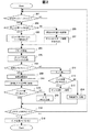
まず、ユーザがステージ20のX,Y駆動機構を操作し、図6のように、スライドガラス1とカバーガラス2に挟まれた標本601の点A(X1,Y1)を対物レンズ14に対向させ、観察を開始する場合について説明する。この段階では、点Aは対物レンズ14には合焦しておらず、Z座標は、初期値である座標Z0(図7)にある。ユーザが、AFボタン33aを押下することによりAF動作の開始を指示した場合には、CPU33bは、それを検出し、ピント位置メモリ33d内にすでに合焦位置のZ座標が格納されているかどうかを確認する(図2のステップ201,202)。格納されていない場合には、現在のZ座標Z0を初期値として初期値メモリ33eに格納する。その後、サーチ範囲を設定するために予め定められているZ座標であるZminとZmaxとをメモリ33cから読み出す(ステップ206,207)。座標Zminと座標Zmaxは、ステージ20の可動範囲内で予め定められた絶対座標であり、座標Zminから座標Zmaxまで距離は、ここでは0.50mmである。この0.50mmという数値は、スライドガラスの厚さの規格が、0.9mmから1.2mmであることを考慮して定めた値である。
【0023】
つぎに、ステップ204に進み、ステージ20の駆動モータに制御信号を出力し、設定したZ座標の範囲である座標Zminから座標Zmaxまでステージ20を移動させる(ステップ204)。ステージ20が座標Zminから座標Zmaxまで移動している間、予め定めたサンプリング間隔で、CPU33bは、カメラヘッド31が取り込んだ画像のコントラストを検出し、検出したコントラスト値とZ座標との関係をプロファイルする(ステップ205)。得られたプロファイルの中に合焦位置を表す山形のプロファイルが含まれているかどうかを判断し(ステップ208)、含まれていればコントラストのピーク位置のZ座標Z1(図7)を求めることにより合焦位置を算出する(ステップ209)。そして、検出した合焦位置の座標Z1までステージ20を移動させるように、モータに制御信号を出力する(ステップ210)。これにより、ステージ20は、合焦位置の座標Z1まで移動して停止する。これにより、ユーザは合焦状態で観察を行うことができる。さらにCPU33bは、ピント位置メモリ33dに合焦位置のZ座標のデータが既に格納されているかどうかを確認する(ステップ215)。ここでは、まだピント位置メモリ33dにはZ座標は格納されていないので、ステップ216で、ステップ209で検出した座標Z1をピント位置メモリ33dに格納する。つぎに、ステップ218に進み、マイクロスイッチ31の出力を確認し、スライドガラス1が装着されているかどうかを確認する。装着されている場合には、同じ試料で観察が続行されていると判断してステップ201に戻る。
【0024】
次に、例えばユーザが図6のように観察位置を点B(X2,Y2)にずらしたため、点BでAF動作を実行させたい場合や、ユーザが点Aの位置のままで自分の好みでステージ20をZ方向に移動させたため、再度点AでAF動作を実行させたい場合、ユーザは再びAFボタン33aを押す。CPU33bはステップ201でこれを検出し、ステップ202においてピント位置メモリ33dにZ座標が格納されているかどうかを確認する。ピント位置メモリ33dには、先ほどステップ216で格納した座標Z1が記憶されているので、今度はステップ203に進む。ステップ203では、ピント位置メモリ33dに格納されている座標Z1を読み出して、これを中心に予め定めた範囲を設定して、サーチ範囲を決定する。具体的には、ピント位置メモリ33dに格納されている座標Z1に予め定めた±20μmを加えることにより、座標(Z1−20μm)から座標(Z1+20μm)の範囲をサーチ範囲として決定する。この範囲は、ステップ207で設定した0.5mmのサーチ範囲よりも10分の1以下の狭い範囲である。
【0025】
つぎにステップ204、205において、設定したZ1±20μmのサーチ範囲について、ステージ20を移動させ、コントラストを検出し、プロファイルを得る。山形のプロファイルが含まれている場合には、ピークのコントラスト値のZ座標を検出することにより、あらたな合焦位置の座標Z2を求める(ステップ208,209)。求めた合焦位置の座標Z2までステージ20を移動させ停止させることにより、合焦状態で観察を行うことができる。なお、この場合は、既にピント位置メモリ33dに点Aの合焦位置の座標Z1が格納されているので、ステップ215ではあらたな座標Z2の格納は行わず、そのままステップ218に進む。スライドガラス1が外されていなければ、同じ試料で観察を続行していると判断して、そのままステップ201に戻る。
【0026】
このように、既にピント位置メモリ33に合焦位置の座標が格納されている場合には、同じスライドガラス1の標本の厚さにばらつきがあることによるピントずれのみを考慮すればよいため、ステップ203で決定するサーチを行うZ範囲を、初期のサーチ範囲(ステップ207)よりも大幅に狭めることができるため、同じ試料についての2回目以降のAF動作を高速に行うことができる。なお、サーチ範囲は、ここでは初期のステップ207では絶対座標の座標Zminと座標Zmaxで定める0.5mmの範囲、2回目以降を1回目の合焦位置の座標Z1±20μmと定めているが、数値はこれに限定されるものではなく、ステージ20のZ方向のストローク、ユーザが通常用いる標本の厚さのばらつきを考慮して決定することができる。なお、2回目以降のサーチ範囲の数値(ここでは±20μm)をユーザが入力するように構成することも可能である。
【0027】
また、ステップ208で、山形のプロファイルが得られなかった場合には、スライドガラス1上で標本の存在しない部分を観察していると考えられるので、そのことを知らせるエラー表示をモニター34に表示させる(ステップ211)。その後、ピント位置メモリ33dに合焦位置の座標が格納されているかどうかを確認し、合焦位置の座標Z1が格納されている場合にはそれを読み出して、ステージ20を座標Z1に移動させる。ピント位置メモリ33dに座標が格納されていない場合には、初期値メモリ33eに格納されている初期座標Z0を読み出し、ステージ20を初期座標Z0に格納する。これにより、山形プロファイルが得られなかった場合であっても、同じ試料についての前回以前の合焦位置の座標Z1、もしくは、初期位置Z0に戻ることができる。
【0028】
また、ステップ218でスライドガラス1が外されたことを検出した場合には、すでに格納した合焦位置の座標Z1および初期値Z0は別の試料には使えないため、ピント位置メモリ33dおよび初期値メモリ33e内のデータをすべて消去する。
【0029】
このように、第1の実施の形態の顕微鏡システムによれば、1回目のAF動作で検出した座標Z1をピント位置メモリ33dに格納することにより、ユーザが同じ試料内でX、Y座標を移動させた場合や、同じX,Y座標であってもユーザがZ座標を移動させた場合に、座標Z1を中心に狭いサーチ範囲で合焦位置を検出できるため、素早く合焦位置を検出することができる。また、スライドガラス1上の標本がない部位でユーザがAF動作を行わせた場合であっても、1回目の合焦位置の座標Z1もしくは初期座標Z0に戻ることができる。
【0030】
また、試料が別の試料に交換された場合には、それをステップ218で検出してピント位置メモリ33d、初期値メモリ33eを消去するため、試料ごとにZ座標をリセットすることができる。
【0031】
なお、上述の第1の実施の形態では、1回目のAF動作で検出した座標Z1を、別の試料に交換されない限り、ピント位置メモリ33dに格納し続ける構成であるが、ステップ215でイエスであった場合に、ステップ218の前に、今回のAF動作でステップ209で検出した座標、例えばZ2をピント位置メモリ33dに格納することにより、ピント位置メモリ33dの記憶する座標をAF動作の度に、毎回更新する構成にすることも可能である。
(第2の実施の形態)
つぎに、本発明の第2の実施の形態の顕微鏡システムについて説明する。
【0032】
本発明の実施形態の顕微鏡システム810は、図8,図9のように顕微鏡の構成要素である、光源12、コンデンサレンズ13、ステージ20、対物レンズ14、第2対物レンズ15等の光学系およびステージ20の駆動機構は、全て箱状のハウジング41に収められている。また、第2の実施の形態の顕微鏡システムは、接眼レンズ17は備えず、撮像素子32を内蔵している。撮像素子32によって取得した信号は、ハウジング内に配置された画像処理部33で処理され、画像をモニタ34に写しだす構成である。ステージの移動、ピント合わせ、倍率の切換等の駆動機構は、全て電動化されており、付属のコントロールパット36によって操作する。
【0033】
ステージ20は、Y方向に移動するクロスローラガイド25の上にX方向に移動するクロスローラガイド26が搭載された形状となっている。それぞれに、ステッピングモータ(不図示)とリードネジ(不図示)を含んでいる。X方向のクロスローラガイド26には載物台27が搭載されている。よって、載物台27は、クロスローラーガイド25,26によって、X方向、Y方向に電動駆動させることができる。また、Y方向クロスローラガイド25は、不図示のZ機構に搭載され、モータによりZ方向に駆動することができる。載物台27には矩形の開口部が設けられており、スライドガラス1を保持することができる。ステージ20は、X方向の可動範囲が大きくとられており、載物台27のスライドガラス保持部の全てを、ハウジング41のスリット状の開口部41aからハウジング41の外まで移動することができる。観察者が、付属のコントロールパッド36によりディスプレイ上の表示されているローディングボタン35をクリックすると、載物台27を開口41aからロード(外部からハウジング41内への引き込み)、アンロード(ハウジング41から外部への吐き出し)を行うことができる。
【0034】
画像処理部33の動作は、第1の実施の形態とほとんど同様であるが、第2の実施の形態では、ローディングの操作が標本交換と判断できるので、図2のステップ218でスライドガラス1が外されたかどうかを判断するために、CPU33bは、観察者がアンロードの操作を行ったかどうかを判断する。ユーザがアンロードの操作を行った場合には、ステップ219でピント位置メモリを消去する。これにより、第1の実施の形態と同様の効果が得られる。
【0035】
なお、第2の実施の形態の顕微鏡システムにおいて、載物台27にスライドガラスが装着されているかどうかを検出するための検出部を配置し、この検出部の検出結果により、図2のステップ218でスライドガラス1が外されたかどうか検出する構成にすることも可能である。
(第3の実施の形態)
本発明の実施の形態の顕微鏡システムを図10に示す。本実施形態の構成は第2実施の形態の顕微鏡システムと同様の構成であるが、ハウジング41の開口41aの内側に、スライドガラス1に付されたバーコード等の識別記号を読み取る読みとり部42を付加したものである。よって、スライドガラス1として、図11に示したようにスライドガラス1ごとの固有の記号であるバーコード3が添付されているものを用いることにより、載物台27に搭載されたスライドガラス1を特定することができる。
【0036】
第3の実施の形態では、ハウジング41内の画像処理部33は、メモリ33c内に、ピント位置メモリ33dと初期値メモリ33eの他に、バーコード3の情報と合焦位置のZ座標とを対応させたテーブルを格納するための領域であるバーコード情報メモリ33fをさらに有している。
【0037】
画像処理部33の動作は、図12,図13に示したように第1の実施の形態の図2とほぼ同様であるが、図12のようにステップ201の前に、観察者が付属のコントロールパッド36で試料をロードする操作をした場合には、ステップ1201で読みとり部42にバーコードの読みとりを指示し、読みとったバーコード情報をバーコード情報メモリ33fのテーブルに参照し、同じバーコード情報が格納されているかどうか検索する。同じ情報がある場合には、対応するZ座標の情報を読み出し、これがこのスライドガラス1について前回以前のAF動作で格納した合焦位置のZ座標であるので、ピント位置メモリ33dに、このZ座標を格納する。この後、ステップ201以降に進む。これにより、そのスライドガラス1について以前AF動作を行っていれば、そのときのZ座標を用いてステップ203で狭いサーチ範囲を決定することができるので、狭い範囲をサーチして素早く合焦位置を検出できる。
【0038】
また、図13のステップ218でアンロードされたことを検出した場合、もしくはスライドガラス1が外されたことを検出した場合には、ステップ1301に進み、ステップ1201で検出したバーコード情報と同じ情報がバーコード情報メモリ33fに格納されているかどうか確認し、格納されていない場合には、ピント位置メモリ33dに現在格納されているZ座標をバーコード情報と対応させて、バーコード情報メモリ33fに格納する。その後、ステップ219に進み、ピント位置メモリ33d内のデータを消去する。これにより、次回、同じスライドガラス1が載物台27に搭載された場合には、今回格納したZ座標をステップ1203で読み出して用いることができる。
【0039】
このように、第3の実施の形態の顕微鏡システムによれば、スライドガラス1ごとに固有の合焦位置のZ座標を記憶することができるため、過去にスライドガラス1についてAF動作を行っていれば、狭い範囲のサーチで素早く合焦位置を検出することができる。
【0040】
なお、上述の第1、第2、第3の実施の形態では、図2のようにAFボタン33aが操作されたならばAF動作を開始し、AF動作終了後は再びAFボタン33aが操作されない限りAF動作を開始しない構成であるが、本発明はこれに限定されるものではなく、一旦AFボタン33aが押下されたならば連続的にAF動作を行う構成することも可能である。これは、図2の場合、例えばステップ218でNOであった場合に、ステップ202に戻るようにすることにより実現可能である。
【0041】
【発明の効果】
本発明では、コントラスト方式のAF機能を備えた顕微鏡システムにおいて、素早く合焦位置を検出することのできるシステムを提供することができる。
【図面の簡単な説明】
【図1】図1は、本発明の第1の実施の形態のAF装置を備えた顕微鏡システムの全体構成を示す説明図である
【図2】図2は、図1の顕微鏡システムのAF動作を示すフローチャートである。
【図3】図3は、図1の顕微鏡システムのステージ20の上面図である。
【図4】図4は、図3のステージの標本ホルダ21がスライドガラス1を保持している状態の上面図である。
【図5】図5は、図3のステージの標本ホルダ21がスライドガラス1を保持していない状態の上面図である。
【図6】図6は、スライドガラス1上の標本601を示す説明図である。
【図7】図7は、図1の顕微鏡システムのAF動作の際の、ステージ20のZ方向のサーチ範囲を示す説明図である。
【図8】図8は、本発明の第2の実施の形態のAF装置を備えた顕微鏡システムの全体構成を示す説明図である。
【図9】図9は、図8の顕微鏡システムの顕微鏡810の内部構造を示す切り欠き斜視図である。
【図10】図10は、本発明の第3の実施の形態のAF装置を備えた顕微鏡システムの顕微鏡1010の構成を示す切り欠き斜視図である。
【図11】図11は、第3の実施の形態の顕微鏡システムで用いるスライドガラス1とそのバーコード3を示す上面図である。
【図12】図12は、第3の実施の形態の顕微鏡システムのAF動作を示すフローチャートである。
【図13】図13は、第3の実施の形態の顕微鏡システムのAF動作を示すフローチャートである。
【図14】図14は、従来のAF動作で得られるコントラスト値を縦軸、そのときのステージのZ座標を横軸としてプロファイルしたグラフである。
【符号の説明】
1 スライドガラス
2 カバーガラス
3 識別記号
10 顕微鏡
11 顕微鏡本体
12 光源
13 コンデンサ
14 対物レンズ
15 第2対物レンズ
16 鏡筒
17 接眼レンズ
18 直筒
20 ステージ
21 標本ホルダ
22 固定爪
23 可動爪
24 固定ネジ
25 Y方向クロスローラガイド
26 X方向クロスローラガイド
27 載物台
31 カメラヘッド
33 画像処理部
33a AFボタン
33b CPU
33c メモリ
33d ピント位置メモリ
33e 初期値メモリ
33f バーコード情報メモリ
34 モニタ
35 ロードボタン表示
36 操作パッド
41 ハウジング
42 読み取り部[0001]
TECHNICAL FIELD OF THE INVENTION
The present invention relates to a microscope having an autofocus (hereinafter, referred to as AF) function.
[0002]
[Prior art]
A microscope system including an image contrast type AF device is known. In this microscope system, the sample stage is moved in the Z-axis direction while detecting the contrast of a captured image, and the Z coordinate at which the contrast value is maximized is set as the focus position. As the operation of the AF device, for example, the detected contrast is profiled while moving the stage in the positive direction of the Z axis, and a mountain-shaped profile is obtained as shown in the graph of FIG. The Z coordinate of the contrast maximum value of this chevron profile (coordinate Z in FIG. 14) F ) And the obtained coordinates Z F The stage is moved in the minus direction of the Z-axis until returning. With this, the stage is moved to the coordinate Z F And the focusing is completed.
[0003]
In this case, a problem is that a range (a range b in FIG. 14) in which a mountain-shaped profile is obtained with respect to a movement range of the Z axis of the stage for searching for a focus position (a range a in FIG. 14). It is very small. Since it takes time to move the stage over the range a, the coordinates Z of the in-focus position from the start of the AF operation F Therefore, it is difficult to shorten the time until the stage is finally stopped. As an example of a technique for shortening the time, there is known a method in which a range a in which the stage moves in the Z-axis direction can be limited in advance by a user, and only the range a is searched.
[0004]
[Problems to be solved by the invention]
However, when the search range a can be limited by the user as described above, the focus position may exist outside the search range a. For example, when observing a sample sandwiched between glass slides as a sample, the thickness of the glass slide, the thickness of the sample itself enclosed between the glass slide and the cover glass, etc. are not constant, but vary, If the search range is extremely narrowed, a focus position may exist outside the search range depending on the sample. For this reason, there is a limit to narrowing the search range a.
[0005]
An object of the present invention is to provide a microscope system having a contrast type AF function, which can quickly detect a focus position.
[0006]
[Means for Solving the Problems]
In order to achieve the above object, according to the present invention, the following microscope system is provided.
[0007]
That is, a stage on which a sample is mounted, an optical system that forms a sample image, an imaging unit that captures the sample image, a contrast detection unit that detects a contrast value of an image captured by the imaging unit, and the contrast detection unit A focus position detection unit that captures the detected contrast value and detects a focus position based on the contrast value; a detection instruction operation unit that instructs the operation of the focus position detection unit; and an instruction of the detection instruction operation unit. Once the in-focus position detecting unit detects the in-focus position, a storage unit for storing the in-focus position until a reset operation is performed, and the reset operation for resetting the storage contents of the storage unit And a reset detection unit for detecting
The focus position detection unit reads out the focus position stored in the storage unit and sets a predetermined range around the read focus position every time the instruction operation of the detection instruction operation unit is performed. Then, the stage and the optical system are relatively moved by using the range as a movement range, the focus position is detected, the reset detection unit detects the reset operation, and the storage content of the storage unit is erased. The microscope system is characterized in that the same focus position is repeatedly read until the operation is performed.
[0008]
In the microscope system, the reset detection unit may be configured to detect the operation of removing the sample from the stage, which is the reset operation.
[0009]
In the microscope system, the stage, the optical system, and the imaging unit may be configured to be housed in a housing, and the stage may include a stage on which a sample is mounted, and a housing. A moving unit that projects the article table from the opening provided to the outside, and the reset detection unit causes the moving section to project the article table from the housing to the outside as the reset operation. It can be configured to detect an action.
[0010]
In the above-mentioned microscope system, it is possible to further include a second storage unit for storing an initial position of the stage, wherein the focus position detection unit is configured to store a focus position in the storage unit. After the current stage position is stored in the second storage unit, the stage is moved in a predetermined second movement range wider than the movement range, and the focus position is detected. When the in-focus position cannot be detected, the stage may be returned to the stage position stored in the second storage unit.
[0011]
Further, according to the present invention, the following microscope system is provided.
[0012]
That is, a stage on which a sample is mounted, an optical system for forming a sample image, a mounting portion for mounting an imaging device that captures the sample image and detects contrast, and captures the contrast value from the imaging device. A focus position detection unit that detects a focus position based on the contrast value; a storage unit that stores the focus position detected by the focus position detection unit; and a memory that resets the storage content of the storage unit. A reset detection unit for detecting a reset operation of
The in-focus position detection unit reads out the in-focus position stored in the storage unit, sets a predetermined range around the read out in-focus position, and moves the stage using the range as a movement range. The focus position is detected, and when the reset detection unit detects the reset operation, the contents stored in the storage unit are erased.
[0013]
Further, according to the present invention, the following microscope system is provided.
[0014]
That is, a focus position detecting means used for a microscope to detect a focus position of an observation optical system that focuses on a sample,
Focus position storage means for storing the focus position information detected by the focus position detection means,
A search means for determining a search range from the focus position information, and instructing the focus position detection means to perform a focus position detection operation of the observation optical system within the search range,
Reset means for resetting the focus position information stored in the storage means; and once the focus position information is stored in the focus position storage means, the storage is maintained until the reset means is activated. Control means for operating the search means within a search range determined based on the stored focus position information,
Is a microscope system provided with.
[0015]
In the above-described microscope system, the microscope system may be configured to include a slide glass detection unit that detects a replacement operation of a slide glass holding the specimen, and an identification information detection unit that detects unique identification information given to the slide glass. In this case, the reset unit performs the reset operation based on a detection signal from the slide glass detection unit, and the control unit removes the slide glass based on the detection signal from the slide glass detection unit. When the operation is detected, the unique identification information given to the slide glass and the focus position information are stored in association with each other. On the other hand, when the mounting operation of the slide glass is detected, the identification is performed. The information detecting unit detects the identification information, reads out the focusing position information corresponding to the identification information, It can be configured to store the read focus position information in the position storage means focus.
[0016]
BEST MODE FOR CARRYING OUT THE INVENTION
Hereinafter, a microscope system according to an embodiment of the present invention will be described.
(First Embodiment)
A microscope system according to the first embodiment will be described with reference to FIGS.
[0017]
The microscope system according to the first embodiment includes a
[0018]
Further, as shown in FIG. 3, the
[0019]
In such a microscope system, when a sample sandwiched between the
[0020]
Hereinafter, the focusing operation of the AF device will be described with reference to FIGS.
[0021]
The
[0022]
First, the user operates the X, Y drive mechanism of the
[0023]
Next, the process proceeds to step 204, where a control signal is output to the drive motor of the
[0024]
Next, for example, when the user shifts the observation position to the point B (X2, Y2) as shown in FIG. When the user wants to execute the AF operation again at the point A because the
[0025]
Next, in
[0026]
As described above, when the coordinates of the focus position are already stored in the
[0027]
If a mountain-shaped profile is not obtained in
[0028]
If it is detected in
[0029]
As described above, according to the microscope system of the first embodiment, the user moves the X and Y coordinates within the same sample by storing the coordinates Z1 detected in the first AF operation in the
[0030]
Further, when the sample is replaced with another sample, it is detected in
[0031]
In the above-described first embodiment, the coordinate Z1 detected in the first AF operation is stored in the
(Second embodiment)
Next, a microscope system according to a second embodiment of the present invention will be described.
[0032]
A
[0033]
The
[0034]
The operation of the
[0035]
In the microscope system according to the second embodiment, a detection unit for detecting whether or not the slide glass is mounted on the
(Third embodiment)
FIG. 10 shows a microscope system according to an embodiment of the present invention. The configuration of the present embodiment is the same as the configuration of the microscope system of the second embodiment, except that a
[0036]
In the third embodiment, the
[0037]
The operation of the
[0038]
If it is detected in
[0039]
As described above, according to the microscope system of the third embodiment, since the Z coordinate of the in-focus position unique to each
[0040]
In the first, second, and third embodiments, the AF operation is started if the
[0041]
【The invention's effect】
According to the present invention, it is possible to provide a microscope system having a contrast type AF function that can quickly detect a focus position.
[Brief description of the drawings]
FIG. 1 is an explanatory diagram illustrating an overall configuration of a microscope system including an AF device according to a first embodiment of the present invention.
FIG. 2 is a flowchart illustrating an AF operation of the microscope system in FIG. 1;
FIG. 3 is a top view of a
FIG. 4 is a top view showing a state in which the
FIG. 5 is a top view showing a state where the
FIG. 6 is an explanatory diagram showing a
FIG. 7 is an explanatory diagram showing a search range of the
FIG. 8 is an explanatory diagram illustrating an overall configuration of a microscope system including an AF device according to a second embodiment of the present invention.
FIG. 9 is a cutaway perspective view showing an internal structure of a
FIG. 10 is a cutaway perspective view showing a configuration of a
FIG. 11 is a top view illustrating a
FIG. 12 is a flowchart illustrating an AF operation of the microscope system according to the third embodiment.
FIG. 13 is a flowchart illustrating an AF operation of the microscope system according to the third embodiment.
FIG. 14 is a graph in which the vertical axis represents the contrast value obtained by the conventional AF operation, and the horizontal axis represents the Z coordinate of the stage at that time.
[Explanation of symbols]
1 slide glass
2 Cover glass
3 Identification code
10 microscope
11 Microscope body
12 light source
13 Capacitor
14 Objective lens
15 Second objective lens
16 lens barrel
17 Eyepiece
18 straight cylinder
20 stages
21 Specimen holder
22 Fixed nail
23 movable claws
24 Fixing screw
25 Y direction cross roller guide
26 X-direction cross roller guide
27 Loading table
31 Camera Head
33 Image processing unit
33a AF button
33b CPU
33c memory
33d focus position memory
33e Initial value memory
33f barcode information memory
34 monitors
35 Load button display
36 Operation pad
41 Housing
42 Reading unit
Claims (7)
前記合焦位置検出部は、前記検出指示操作部の指示動作が入る毎に、前記記憶部に記憶されている合焦位置を読み出して、読み出した合焦位置を中心に予め定めた範囲を設定して、該範囲を移動範囲として前記ステージと前記光学系とを相対的に移動させ前記合焦位置を検出し、前記リセット検出部が前記リセット動作を検出し、前記記憶部の記憶内容が消去されるまで、繰り返し同一の前記合焦位置が読み出されることを特徴とする顕微鏡システム。A stage on which a sample is mounted, an optical system that forms the sample image, an imaging unit that captures the sample image, a contrast detection unit that detects a contrast value of an image captured by the imaging unit, and detection of the contrast detection unit A focus position detection unit that detects the focus position based on the contrast value, a detection instruction operation unit that instructs the operation of the focus position detection unit, and a detection instruction operation unit that instructs the operation of the detection instruction operation unit. Once the focus position detection unit detects the focus position, a storage unit for storing the focus position until a reset operation is performed, and the reset operation is detected to reset the storage content of the storage unit A reset detection unit that performs
The focus position detection unit reads out the focus position stored in the storage unit and sets a predetermined range around the read focus position every time the instruction operation of the detection instruction operation unit is performed. Then, the stage and the optical system are relatively moved by using the range as a movement range, the focus position is detected, the reset detection unit detects the reset operation, and the storage content of the storage unit is erased. The same in-focus position is repeatedly read until the operation is performed.
前記ステージは、標本を載置する載物台と、前記筐体に設けられた開口から前記載物台を外部に突出させる移動部とを有し、
前記リセット検出部は、前記リセット動作として、前記移動部が前記載物台を前記筐体から外部に突出させる動作を検出することを特徴とする顕微鏡システム。The microscope system according to claim 2, wherein the stage, the optical system, and the imaging unit are housed in a housing,
The stage has a stage on which a sample is placed, and a moving unit that projects the stage to the outside from an opening provided in the housing,
The microscope system, wherein the reset detection unit detects, as the reset operation, an operation in which the moving unit projects the stage from the housing to the outside.
前記合焦位置検出部は、前記記憶部に合焦位置が記憶されていない場合には、現在の前記ステージ位置を前記第2記憶部に記憶させた後、前記移動範囲より広い予め定めた第2の移動範囲において前記ステージを移動させ前記合焦位置を検出し、この動作により合焦位置が検出できなかった場合には、前記第2記憶部に記憶されている前記ステージ位置まで前記ステージを戻すことを特徴する顕微鏡システム。The microscope system according to claim 1, further comprising a second storage unit for storing an initial position of the stage,
When the focus position is not stored in the storage unit, the focus position detection unit stores the current stage position in the second storage unit, and then stores a predetermined second position that is wider than the movement range. The focus position is detected by moving the stage in the movement range of 2. If the focus position cannot be detected by this operation, the stage is moved to the stage position stored in the second storage unit. A microscope system characterized by returning.
前記合焦位置検出部は、前記記憶部に記憶されている合焦位置を読み出して、読み出した合焦位置を中心に予め定めた範囲を設定して、該範囲を移動範囲として前記ステージを移動させ前記合焦位置を検出し、前記リセット検出部が前記リセット動作を検出した場合には、前記記憶部の記憶内容を消去することを特徴とする顕微鏡システム。A stage for mounting the sample, an optical system for forming the sample image, a mounting portion for mounting an imaging device for capturing the sample image and detecting a contrast, and capturing the contrast value from the imaging device; A focus position detection unit for detecting a focus position based on a value; a storage unit for storing the focus position detected by the focus position detection unit; and a reset for resetting the storage content of the storage unit A reset detection unit for detecting an operation,
The in-focus position detection unit reads out the in-focus position stored in the storage unit, sets a predetermined range around the read out in-focus position, and moves the stage using the range as a movement range. The microscope system according to claim 1, wherein the focus position is detected, and when the reset detection unit detects the reset operation, the storage content of the storage unit is erased.
前記合焦位置検出手段により検出された前記合焦位置情報を記憶する合焦位置記憶手段と、
前記合焦位置情報からサーチ範囲を決定し、前記サーチ範囲内で前記観察光学系の合焦位置検出動作を行うように前記合焦位置検出手段に指示するサーチ手段と、
前記記憶手段に記憶された前記合焦位置情報をリセットするリセット手段と、
前記合焦位置記憶手段に前記合焦位置情報が一旦記憶されると、前記リセット手段が作動するまで、前記記憶を維持させ、前記記憶された合焦位置情報に基づき決められたサーチ範囲内で前記サーチ手段を動作させる制御手段と、
を備えた顕微鏡システム。Focusing position detection means used in a microscope to detect the focusing position of the observation optical system that focuses on the sample,
Focus position storage means for storing the focus position information detected by the focus position detection means,
A search means for determining a search range from the focus position information, and instructing the focus position detection means to perform a focus position detection operation of the observation optical system within the search range,
Reset means for resetting the focus position information stored in the storage means,
Once the in-focus position information is stored in the in-focus position storage means, the storage is maintained until the reset means operates, within a search range determined based on the stored in-focus position information. Control means for operating the search means;
Microscope system equipped with.
前記標本を保持するスライドガラスの差し替え動作を検出するスライドガラス検出部と、
前記スライドガラスに付与された固有の識別情報を検出する識別情報検出部とを有し、
前記リセット手段は、前記スライドガラス検出部からの検出信号に基づき前記リセット動作を行い、
前記制御手段は、前記スライドガラス検出部の検出信号に基づき、前記スライドガラスの取り出し動作を検出した場合には、前記スライドガラスに付与された固有の識別情報と、前記合焦位置情報とを関連付けて記憶し、一方、前記スライドガラスの装着動作を検出した場合には、前記識別情報検出部により前記識別情報を検知し、前記識別情報に対応する前記合焦位置情報を読み出し、前記合焦位置記憶手段に前記読み出した合焦位置情報を記憶させることを特徴とする顕微鏡システム。The microscope system according to claim 6,
A slide glass detection unit that detects a replacement operation of the slide glass holding the sample,
An identification information detection unit that detects unique identification information given to the slide glass,
The reset unit performs the reset operation based on a detection signal from the slide glass detection unit,
The control unit associates the unique identification information given to the slide glass with the focus position information when detecting the operation of removing the slide glass based on the detection signal of the slide glass detection unit. On the other hand, when the mounting operation of the slide glass is detected, the identification information is detected by the identification information detection unit, and the focusing position information corresponding to the identification information is read out, and the focusing position is read. A microscope system, wherein the focus position information read out is stored in a storage unit.
Priority Applications (3)
| Application Number | Priority Date | Filing Date | Title |
|---|---|---|---|
| JP2002221520A JP2004061942A (en) | 2002-07-30 | 2002-07-30 | Microscope system |
| US10/625,545 US7167305B2 (en) | 2002-07-30 | 2003-07-24 | Microscope system |
| US11/633,458 US7262908B2 (en) | 2002-07-30 | 2006-12-05 | Microscope system |
Applications Claiming Priority (1)
| Application Number | Priority Date | Filing Date | Title |
|---|---|---|---|
| JP2002221520A JP2004061942A (en) | 2002-07-30 | 2002-07-30 | Microscope system |
Publications (2)
| Publication Number | Publication Date |
|---|---|
| JP2004061942A true JP2004061942A (en) | 2004-02-26 |
| JP2004061942A5 JP2004061942A5 (en) | 2005-11-04 |
Family
ID=31941808
Family Applications (1)
| Application Number | Title | Priority Date | Filing Date |
|---|---|---|---|
| JP2002221520A Pending JP2004061942A (en) | 2002-07-30 | 2002-07-30 | Microscope system |
Country Status (2)
| Country | Link |
|---|---|
| US (2) | US7167305B2 (en) |
| JP (1) | JP2004061942A (en) |
Cited By (10)
| Publication number | Priority date | Publication date | Assignee | Title |
|---|---|---|---|---|
| JP2007010500A (en) * | 2005-06-30 | 2007-01-18 | Canon Inc | Sample detection device and specimen analyzer including it |
| JP2007034053A (en) * | 2005-07-28 | 2007-02-08 | Fujifilm Holdings Corp | Imaging apparatus |
| JP2007101578A (en) * | 2005-09-30 | 2007-04-19 | Olympus Corp | Microscopic focus maintenance device and microscope device |
| JP2008023065A (en) * | 2006-07-21 | 2008-02-07 | Pola Chem Ind Inc | Assessment apparatus of horny layer cell |
| JP2009036969A (en) * | 2007-08-01 | 2009-02-19 | Nikon Corp | Cover glass, slide glass, preparation, observation method, and microscopic device |
| JP2011095500A (en) * | 2009-10-29 | 2011-05-12 | Olympus Corp | Microscope device and microscopic observation method |
| JP2011237439A (en) * | 2011-06-23 | 2011-11-24 | Canon Inc | Sample detecting device and sample analyzing device including the same |
| US8233075B2 (en) | 2007-05-24 | 2012-07-31 | Gyrus Acmi, Inc. | User-aided auto-focus |
| JP2014126608A (en) * | 2012-12-25 | 2014-07-07 | Olympus Corp | Microscope system |
| WO2014199696A1 (en) * | 2013-06-12 | 2014-12-18 | 浜松ホトニクス株式会社 | Sample retaining member insertion-removal mechanism and image acquisition device |
Families Citing this family (21)
| Publication number | Priority date | Publication date | Assignee | Title |
|---|---|---|---|---|
| EP1793256A4 (en) * | 2004-06-14 | 2010-05-26 | Olympus Corp | Optical scanning microscope observing device |
| US7199712B2 (en) * | 2004-06-17 | 2007-04-03 | Tafas Triantafyllos P | System for automatically locating and manipulating positions on an object |
| JP2009545782A (en) * | 2006-08-04 | 2009-12-24 | イコニシス インコーポレーテッド | Microscope slide mounting member for Z movement |
| US8878923B2 (en) * | 2007-08-23 | 2014-11-04 | General Electric Company | System and method for enhanced predictive autofocusing |
| JP2011221188A (en) * | 2010-04-07 | 2011-11-04 | Sony Corp | Stage control device, stage control method and microscope |
| HK1150495A2 (en) * | 2010-04-12 | 2011-12-30 | Netop Ind Company Ltd | Microscope |
| US9522396B2 (en) | 2010-12-29 | 2016-12-20 | S.D. Sight Diagnostics Ltd. | Apparatus and method for automatic detection of pathogens |
| EP2798350B1 (en) | 2011-12-29 | 2021-07-28 | Sight Diagnostics Ltd. | Methods and systems for detecting a pathogen in a biological sample |
| EP2999988A4 (en) | 2013-05-23 | 2017-01-11 | S.D. Sight Diagnostics Ltd. | Method and system for imaging a cell sample |
| IL227276A0 (en) | 2013-07-01 | 2014-03-06 | Parasight Ltd | A method and system for preparing a monolayer of cells, particularly suitable for diagnosis |
| WO2015029032A1 (en) * | 2013-08-26 | 2015-03-05 | Parasight Ltd. | Digital microscopy systems, methods and computer program products |
| CN107077732B (en) | 2014-08-27 | 2020-11-24 | 思迪赛特诊断有限公司 | System and method for calculating focus variation for digital microscope |
| WO2017046799A1 (en) | 2015-09-17 | 2017-03-23 | S.D. Sight Diagnostics Ltd | Methods and apparatus for detecting an entity in a bodily sample |
| WO2017168411A1 (en) | 2016-03-30 | 2017-10-05 | S.D. Sight Diagnostics Ltd | Image processing device for identifying blood parasites |
| US11307196B2 (en) | 2016-05-11 | 2022-04-19 | S.D. Sight Diagnostics Ltd. | Sample carrier for optical measurements |
| CA3022770A1 (en) | 2016-05-11 | 2017-11-16 | S.D. Sight Diagnostics Ltd | Performing optical measurements on a sample |
| DE102016125691B4 (en) * | 2016-12-23 | 2018-10-25 | Leica Microsystems Cms Gmbh | Holder for microscope slide, microscope and method for controlling a microscope |
| KR102419163B1 (en) | 2017-09-29 | 2022-07-08 | 라이카 바이오시스템즈 이미징 인크. | Real-time autofocus focusing algorithm |
| JP7214729B2 (en) | 2017-11-14 | 2023-01-30 | エス.ディー.サイト ダイアグノスティクス リミテッド | Sample container for optical measurement |
| WO2021104776A1 (en) * | 2019-11-29 | 2021-06-03 | Robert Bosch Gmbh | A control unit for focusing a sample and a method thereof |
| CN114324326A (en) * | 2021-12-15 | 2022-04-12 | 长春奥普光电技术股份有限公司 | Rapid imaging screening system and screening method thereof |
Citations (3)
| Publication number | Priority date | Publication date | Assignee | Title |
|---|---|---|---|---|
| JPH04318509A (en) * | 1991-04-17 | 1992-11-10 | Sankyo Seiki Mfg Co Ltd | Automatic focusing device |
| JPH11271624A (en) * | 1998-03-20 | 1999-10-08 | Olympus Optical Co Ltd | Automatic focus detector for microscope |
| JP2002122773A (en) * | 2000-10-13 | 2002-04-26 | Olympus Optical Co Ltd | Focusing unit, electronic camera and focusing method |
Family Cites Families (4)
| Publication number | Priority date | Publication date | Assignee | Title |
|---|---|---|---|---|
| US5932872A (en) * | 1994-07-01 | 1999-08-03 | Jeffrey H. Price | Autofocus system for scanning microscopy having a volume image formation |
| JP3631304B2 (en) | 1995-10-24 | 2005-03-23 | オリンパス株式会社 | Microscope automatic focusing device |
| US6640014B1 (en) * | 1999-01-22 | 2003-10-28 | Jeffrey H. Price | Automatic on-the-fly focusing for continuous image acquisition in high-resolution microscopy |
| SE517626C3 (en) * | 2001-04-12 | 2002-09-04 | Cellavision Ab | Microscopy procedure for scanning and positioning an object, where images are taken and joined in the same image coordinate system to accurately set the microscope table |
-
2002
- 2002-07-30 JP JP2002221520A patent/JP2004061942A/en active Pending
-
2003
- 2003-07-24 US US10/625,545 patent/US7167305B2/en not_active Expired - Lifetime
-
2006
- 2006-12-05 US US11/633,458 patent/US7262908B2/en not_active Expired - Lifetime
Patent Citations (3)
| Publication number | Priority date | Publication date | Assignee | Title |
|---|---|---|---|---|
| JPH04318509A (en) * | 1991-04-17 | 1992-11-10 | Sankyo Seiki Mfg Co Ltd | Automatic focusing device |
| JPH11271624A (en) * | 1998-03-20 | 1999-10-08 | Olympus Optical Co Ltd | Automatic focus detector for microscope |
| JP2002122773A (en) * | 2000-10-13 | 2002-04-26 | Olympus Optical Co Ltd | Focusing unit, electronic camera and focusing method |
Cited By (12)
| Publication number | Priority date | Publication date | Assignee | Title |
|---|---|---|---|---|
| JP2007010500A (en) * | 2005-06-30 | 2007-01-18 | Canon Inc | Sample detection device and specimen analyzer including it |
| JP2007034053A (en) * | 2005-07-28 | 2007-02-08 | Fujifilm Holdings Corp | Imaging apparatus |
| JP2007101578A (en) * | 2005-09-30 | 2007-04-19 | Olympus Corp | Microscopic focus maintenance device and microscope device |
| JP2008023065A (en) * | 2006-07-21 | 2008-02-07 | Pola Chem Ind Inc | Assessment apparatus of horny layer cell |
| US8233075B2 (en) | 2007-05-24 | 2012-07-31 | Gyrus Acmi, Inc. | User-aided auto-focus |
| JP2009036969A (en) * | 2007-08-01 | 2009-02-19 | Nikon Corp | Cover glass, slide glass, preparation, observation method, and microscopic device |
| JP2011095500A (en) * | 2009-10-29 | 2011-05-12 | Olympus Corp | Microscope device and microscopic observation method |
| JP2011237439A (en) * | 2011-06-23 | 2011-11-24 | Canon Inc | Sample detecting device and sample analyzing device including the same |
| JP2014126608A (en) * | 2012-12-25 | 2014-07-07 | Olympus Corp | Microscope system |
| WO2014199696A1 (en) * | 2013-06-12 | 2014-12-18 | 浜松ホトニクス株式会社 | Sample retaining member insertion-removal mechanism and image acquisition device |
| JP2014240931A (en) * | 2013-06-12 | 2014-12-25 | 浜松ホトニクス株式会社 | Withdrawal mechanism for sample holding member and image acquisition device |
| US10088659B2 (en) | 2013-06-12 | 2018-10-02 | Hamamatsu Photonics K.K. | Sample retaining member insertion-removal mechanism and image acquisition device |
Also Published As
| Publication number | Publication date |
|---|---|
| US20040240050A1 (en) | 2004-12-02 |
| US20070081232A1 (en) | 2007-04-12 |
| US7262908B2 (en) | 2007-08-28 |
| US7167305B2 (en) | 2007-01-23 |
Similar Documents
| Publication | Publication Date | Title |
|---|---|---|
| JP2004061942A (en) | Microscope system | |
| JP5021254B2 (en) | Control method of microscope apparatus, microscope apparatus | |
| JP6186634B2 (en) | System equipped with digital microscope and sample inspection method using the same | |
| JP2004061942A5 (en) | ||
| US9277110B2 (en) | Tracking device and tracking method for prohibiting a tracking operation when a tracked subject is obstructed | |
| JP4831972B2 (en) | Micro manipulation system | |
| US8830313B2 (en) | Information processing apparatus, stage-undulation correcting method, program therefor | |
| US9046677B2 (en) | Microscope system and autofocus method | |
| JPH11264937A (en) | Microscope | |
| JP5053691B2 (en) | Specimen scanner device and specimen position detection method using the device | |
| JP2009025349A (en) | Microscope, its control method, and program | |
| JP2005114859A (en) | Microscope | |
| JP5893313B2 (en) | Microscope system | |
| KR20010014602A (en) | Method and apparatus for detecting in-focus state of microscope | |
| JP5959247B2 (en) | microscope | |
| JP6560937B2 (en) | Hardness tester and hardness test method | |
| US7102815B2 (en) | Optical microscope system and optical axis correcting method | |
| JP5305719B2 (en) | Microscope system | |
| JP6797659B2 (en) | Microscope device, program, observation method | |
| JP4754665B2 (en) | Automatic focusing device | |
| JP2021021850A (en) | Autofocus microscope and automatic imaging device of microscopic image | |
| JP7287533B2 (en) | Inspection system, inspection method and program | |
| JP2007124365A (en) | Imaging apparatus | |
| JP5197246B2 (en) | Microscope system | |
| JP2005010665A (en) | Automatic focusing device for microscope and automatic focusing method for microscope |
Legal Events
| Date | Code | Title | Description |
|---|---|---|---|
| A621 | Written request for application examination |
Free format text: JAPANESE INTERMEDIATE CODE: A621 Effective date: 20050704 |
|
| A521 | Written amendment |
Free format text: JAPANESE INTERMEDIATE CODE: A523 Effective date: 20050802 |
|
| RD02 | Notification of acceptance of power of attorney |
Free format text: JAPANESE INTERMEDIATE CODE: A7422 Effective date: 20050802 |
|
| RD04 | Notification of resignation of power of attorney |
Free format text: JAPANESE INTERMEDIATE CODE: A7424 Effective date: 20060830 |
|
| A977 | Report on retrieval |
Free format text: JAPANESE INTERMEDIATE CODE: A971007 Effective date: 20070726 |
|
| A131 | Notification of reasons for refusal |
Free format text: JAPANESE INTERMEDIATE CODE: A131 Effective date: 20070731 |
|
| A521 | Written amendment |
Free format text: JAPANESE INTERMEDIATE CODE: A523 Effective date: 20071001 |
|
| A02 | Decision of refusal |
Free format text: JAPANESE INTERMEDIATE CODE: A02 Effective date: 20071120 |
|
| A521 | Written amendment |
Free format text: JAPANESE INTERMEDIATE CODE: A523 Effective date: 20071220 |
|
| A911 | Transfer of reconsideration by examiner before appeal (zenchi) |
Free format text: JAPANESE INTERMEDIATE CODE: A911 Effective date: 20080306 |
|
| A912 | Removal of reconsideration by examiner before appeal (zenchi) |
Free format text: JAPANESE INTERMEDIATE CODE: A912 Effective date: 20080404 |