JP7201552B2 - REDOX FLOW BATTERY AND METHOD FOR REDOX FLOW BATTERY - Google Patents
REDOX FLOW BATTERY AND METHOD FOR REDOX FLOW BATTERY Download PDFInfo
- Publication number
- JP7201552B2 JP7201552B2 JP2019140397A JP2019140397A JP7201552B2 JP 7201552 B2 JP7201552 B2 JP 7201552B2 JP 2019140397 A JP2019140397 A JP 2019140397A JP 2019140397 A JP2019140397 A JP 2019140397A JP 7201552 B2 JP7201552 B2 JP 7201552B2
- Authority
- JP
- Japan
- Prior art keywords
- electrolyte solution
- cell
- electrode
- iron
- circulation loop
- Prior art date
- Legal status (The legal status is an assumption and is not a legal conclusion. Google has not performed a legal analysis and makes no representation as to the accuracy of the status listed.)
- Active
Links
Images


Classifications
-
- H—ELECTRICITY
- H01—ELECTRIC ELEMENTS
- H01M—PROCESSES OR MEANS, e.g. BATTERIES, FOR THE DIRECT CONVERSION OF CHEMICAL ENERGY INTO ELECTRICAL ENERGY
- H01M8/00—Fuel cells; Manufacture thereof
- H01M8/04—Auxiliary arrangements, e.g. for control of pressure or for circulation of fluids
- H01M8/04082—Arrangements for control of reactant parameters, e.g. pressure or concentration
- H01M8/04186—Arrangements for control of reactant parameters, e.g. pressure or concentration of liquid-charged or electrolyte-charged reactants
-
- H—ELECTRICITY
- H01—ELECTRIC ELEMENTS
- H01M—PROCESSES OR MEANS, e.g. BATTERIES, FOR THE DIRECT CONVERSION OF CHEMICAL ENERGY INTO ELECTRICAL ENERGY
- H01M8/00—Fuel cells; Manufacture thereof
- H01M8/18—Regenerative fuel cells, e.g. redox flow batteries or secondary fuel cells
- H01M8/184—Regeneration by electrochemical means
-
- H—ELECTRICITY
- H01—ELECTRIC ELEMENTS
- H01M—PROCESSES OR MEANS, e.g. BATTERIES, FOR THE DIRECT CONVERSION OF CHEMICAL ENERGY INTO ELECTRICAL ENERGY
- H01M4/00—Electrodes
- H01M4/02—Electrodes composed of, or comprising, active material
- H01M4/36—Selection of substances as active materials, active masses, active liquids
- H01M4/368—Liquid depolarisers
-
- H—ELECTRICITY
- H01—ELECTRIC ELEMENTS
- H01M—PROCESSES OR MEANS, e.g. BATTERIES, FOR THE DIRECT CONVERSION OF CHEMICAL ENERGY INTO ELECTRICAL ENERGY
- H01M8/00—Fuel cells; Manufacture thereof
- H01M8/04—Auxiliary arrangements, e.g. for control of pressure or for circulation of fluids
- H01M8/04082—Arrangements for control of reactant parameters, e.g. pressure or concentration
- H01M8/04201—Reactant storage and supply, e.g. means for feeding, pipes
-
- H—ELECTRICITY
- H01—ELECTRIC ELEMENTS
- H01M—PROCESSES OR MEANS, e.g. BATTERIES, FOR THE DIRECT CONVERSION OF CHEMICAL ENERGY INTO ELECTRICAL ENERGY
- H01M8/00—Fuel cells; Manufacture thereof
- H01M8/04—Auxiliary arrangements, e.g. for control of pressure or for circulation of fluids
- H01M8/04298—Processes for controlling fuel cells or fuel cell systems
- H01M8/04694—Processes for controlling fuel cells or fuel cell systems characterised by variables to be controlled
- H01M8/04791—Concentration; Density
- H01M8/04798—Concentration; Density of fuel cell reactants
-
- H—ELECTRICITY
- H01—ELECTRIC ELEMENTS
- H01M—PROCESSES OR MEANS, e.g. BATTERIES, FOR THE DIRECT CONVERSION OF CHEMICAL ENERGY INTO ELECTRICAL ENERGY
- H01M8/00—Fuel cells; Manufacture thereof
- H01M8/04—Auxiliary arrangements, e.g. for control of pressure or for circulation of fluids
- H01M8/04298—Processes for controlling fuel cells or fuel cell systems
- H01M8/04694—Processes for controlling fuel cells or fuel cell systems characterised by variables to be controlled
- H01M8/04791—Concentration; Density
- H01M8/0482—Concentration; Density of the electrolyte
-
- H—ELECTRICITY
- H01—ELECTRIC ELEMENTS
- H01M—PROCESSES OR MEANS, e.g. BATTERIES, FOR THE DIRECT CONVERSION OF CHEMICAL ENERGY INTO ELECTRICAL ENERGY
- H01M8/00—Fuel cells; Manufacture thereof
- H01M8/08—Fuel cells with aqueous electrolytes
-
- H—ELECTRICITY
- H01—ELECTRIC ELEMENTS
- H01M—PROCESSES OR MEANS, e.g. BATTERIES, FOR THE DIRECT CONVERSION OF CHEMICAL ENERGY INTO ELECTRICAL ENERGY
- H01M8/00—Fuel cells; Manufacture thereof
- H01M8/18—Regenerative fuel cells, e.g. redox flow batteries or secondary fuel cells
- H01M8/184—Regeneration by electrochemical means
- H01M8/188—Regeneration by electrochemical means by recharging of redox couples containing fluids; Redox flow type batteries
-
- H—ELECTRICITY
- H01—ELECTRIC ELEMENTS
- H01M—PROCESSES OR MEANS, e.g. BATTERIES, FOR THE DIRECT CONVERSION OF CHEMICAL ENERGY INTO ELECTRICAL ENERGY
- H01M8/00—Fuel cells; Manufacture thereof
- H01M8/20—Indirect fuel cells, e.g. fuel cells with redox couple being irreversible
-
- H—ELECTRICITY
- H01—ELECTRIC ELEMENTS
- H01M—PROCESSES OR MEANS, e.g. BATTERIES, FOR THE DIRECT CONVERSION OF CHEMICAL ENERGY INTO ELECTRICAL ENERGY
- H01M8/00—Fuel cells; Manufacture thereof
- H01M8/24—Grouping of fuel cells, e.g. stacking of fuel cells
- H01M8/2455—Grouping of fuel cells, e.g. stacking of fuel cells with liquid, solid or electrolyte-charged reactants
-
- H—ELECTRICITY
- H01—ELECTRIC ELEMENTS
- H01M—PROCESSES OR MEANS, e.g. BATTERIES, FOR THE DIRECT CONVERSION OF CHEMICAL ENERGY INTO ELECTRICAL ENERGY
- H01M2300/00—Electrolytes
- H01M2300/0002—Aqueous electrolytes
- H01M2300/0005—Acid electrolytes
-
- H—ELECTRICITY
- H01—ELECTRIC ELEMENTS
- H01M—PROCESSES OR MEANS, e.g. BATTERIES, FOR THE DIRECT CONVERSION OF CHEMICAL ENERGY INTO ELECTRICAL ENERGY
- H01M2300/00—Electrolytes
- H01M2300/0002—Aqueous electrolytes
- H01M2300/0014—Alkaline electrolytes
-
- Y—GENERAL TAGGING OF NEW TECHNOLOGICAL DEVELOPMENTS; GENERAL TAGGING OF CROSS-SECTIONAL TECHNOLOGIES SPANNING OVER SEVERAL SECTIONS OF THE IPC; TECHNICAL SUBJECTS COVERED BY FORMER USPC CROSS-REFERENCE ART COLLECTIONS [XRACs] AND DIGESTS
- Y02—TECHNOLOGIES OR APPLICATIONS FOR MITIGATION OR ADAPTATION AGAINST CLIMATE CHANGE
- Y02E—REDUCTION OF GREENHOUSE GAS [GHG] EMISSIONS, RELATED TO ENERGY GENERATION, TRANSMISSION OR DISTRIBUTION
- Y02E60/00—Enabling technologies; Technologies with a potential or indirect contribution to GHG emissions mitigation
- Y02E60/10—Energy storage using batteries
-
- Y—GENERAL TAGGING OF NEW TECHNOLOGICAL DEVELOPMENTS; GENERAL TAGGING OF CROSS-SECTIONAL TECHNOLOGIES SPANNING OVER SEVERAL SECTIONS OF THE IPC; TECHNICAL SUBJECTS COVERED BY FORMER USPC CROSS-REFERENCE ART COLLECTIONS [XRACs] AND DIGESTS
- Y02—TECHNOLOGIES OR APPLICATIONS FOR MITIGATION OR ADAPTATION AGAINST CLIMATE CHANGE
- Y02E—REDUCTION OF GREENHOUSE GAS [GHG] EMISSIONS, RELATED TO ENERGY GENERATION, TRANSMISSION OR DISTRIBUTION
- Y02E60/00—Enabling technologies; Technologies with a potential or indirect contribution to GHG emissions mitigation
- Y02E60/30—Hydrogen technology
- Y02E60/50—Fuel cells
Landscapes
- Chemical & Material Sciences (AREA)
- Chemical Kinetics & Catalysis (AREA)
- Electrochemistry (AREA)
- General Chemical & Material Sciences (AREA)
- Life Sciences & Earth Sciences (AREA)
- Engineering & Computer Science (AREA)
- Manufacturing & Machinery (AREA)
- Sustainable Development (AREA)
- Sustainable Energy (AREA)
- Fuel Cell (AREA)
Description
本発明は、電解質平衡化特徴及び相溶性実現特徴を有するレドックスフロー電池に関する。 The present invention relates to redox flow batteries with electrolyte balancing and compatibility enabling features.
フロー電池(また、レドックスフロー電池またはレドックスフローセルとしても既知である)は、電気エネルギーを、化学エネルギー(要求があるときに貯蔵し後で放出することができる)に変換するように設計されている。例として、フロー電池は、多くの需要があるときに、消費者需要を超えるエネルギーを貯蔵し、後で当該エネルギーを放出するために、風力発電システム等の再生可能エネルギーシステムとともに使用され得る。 Flow batteries (also known as redox flow batteries or redox flow cells) are designed to convert electrical energy into chemical energy, which can be stored on demand and later released. . As an example, flow batteries can be used with renewable energy systems, such as wind power systems, to store energy in excess of consumer demand when there is high demand, and to release that energy later.
標準的なフロー電池は、イオン交換膜等のセパレータを含み得る電解質層によって分離される負極及び正極を有するレドックスフローセルを含む。負の流体電解質(時々、アノード液と称される)は負極に送達され、正の流体電解質(時々、カソード液と称される)は正極に送達され、レドックスのペアの間で可逆レドックス反応を活発にする。充電するとき、供給される電気エネルギーは、一方の電解質で化学的還元反応を生じ、他方の電解質で酸化反応を生じさせる。セパレータは、電解質が、自由に及び急速に混合することを防止するが、選択されたイオンが、レドックス反応を完了するために通過することを可能にする。放電するとき、液体電解質中に含有される化学エネルギーは、逆反応で放出され、電気エネルギーを電極から引き込むことができる。 A typical flow battery includes a redox flow cell having a negative electrode and a positive electrode separated by an electrolyte layer that may include a separator such as an ion exchange membrane. A negative fluid electrolyte (sometimes referred to as the anolyte) is delivered to the negative electrode and a positive fluid electrolyte (sometimes referred to as the catholyte) is delivered to the positive electrode, allowing reversible redox reactions between the redox pairs. be active. When charging, the supplied electrical energy causes a chemical reduction reaction in one electrolyte and an oxidation reaction in the other electrolyte. The separator prevents the electrolyte from freely and rapidly mixing, but allows selected ions to pass to complete the redox reaction. When discharged, the chemical energy contained in the liquid electrolyte can be released in a reverse reaction and draw electrical energy from the electrodes.
本発明は、不相溶性の電解質の使用を可能にするレドックスフロー電池を提供する。 The present invention provides a redox flow battery that allows the use of incompatible electrolytes.
本開示の例に従ったレッドクスフロー電池は、第1のセル及び第2のセルを含む。各セルは、第1の電極及び第2の電極と、第1の電極と第2の電極との間に配列されるセパレータ層とを有する。第1の循環ループは、第1のセルの第1の電極と流体接続される。ポリ硫化物(polysulfide)電解質溶液は、11.5以上のpHを有し、第1の再循環ループ内に含有される。第2の循環ループは、第2のセルの第2の電極と流体接続される。鉄電解質溶液は、3以下のpHを有し、第2の循環ループ内に含有される。第3の循環ループは、第1のセルの第2の電極と、第2のセルの第1の電極とに流体接続される。仲介電解質(intermediator electrolyte)溶液は、第3の循環ループ内に含有される。第1のセル内のポリ硫化物電解質溶液及び仲介電解質溶液、ならびに第2のセル内の鉄電解質溶液及び仲介電解質溶液は、充電するときに投入電気エネルギーを貯蔵するように及び放電するときに貯蔵された電気エネルギーを放電するように可逆反応するように動作可能である。 A redx flow battery according to an example of the present disclosure includes a first cell and a second cell. Each cell has a first electrode, a second electrode, and a separator layer arranged between the first electrode and the second electrode. A first circulation loop is fluidly connected with the first electrode of the first cell. A polysulfide electrolyte solution has a pH of 11.5 or greater and is contained within the first recirculation loop. A second circulation loop is fluidly connected with the second electrode of the second cell. An iron electrolyte solution has a pH of 3 or less and is contained within the second circulation loop. A third circulation loop is fluidly connected to the second electrode of the first cell and the first electrode of the second cell. An intermediate electrolyte solution is contained within the third circulation loop. The polysulfide electrolyte solution and intermediary electrolyte solution in the first cell, and the iron electrolyte solution and intermediary electrolyte solution in the second cell are configured to store input electrical energy when charging and when discharging. operable to reversibly react to discharge the electrical energy generated.
前述の実施形態のいずれかのさらなる実施形態では、仲介電解質溶液は12以上のpHを有する。 In a further embodiment of any of the preceding embodiments, the intermediary electrolyte solution has a pH of 12 or greater.
前述の実施形態のいずれかのさらなる実施形態では、第1のセルは-0.3V(標準水素電極)よりも大きい標準電極電位を有する。 In a further embodiment of any of the preceding embodiments, the first cell has a standard electrode potential of greater than -0.3 V (standard hydrogen electrode).
前述の実施形態のいずれかのさらなる実施形態では、仲介電解質溶液は、キノキサリン、アントラキノン、またはベンゾキノンのうちの少なくとも1つを含む。 In further embodiments of any of the preceding embodiments, the intermediary electrolyte solution comprises at least one of quinoxaline, anthraquinone, or benzoquinone.
前述の実施形態のいずれかのさらなる実施形態では、仲介電解質溶液は、1,2-ベンゾキノン-3,5-ジスルホン酸を含む。 In a further embodiment of any of the preceding embodiments, the intermediary electrolyte solution comprises 1,2-benzoquinone-3,5-disulfonic acid.
前述の実施形態のいずれかのさらなる実施形態では、仲介電解質溶液は、2,6-DBEAQ、1,2-DBEAQ、または1,8-DBEAQのうちの少なくとも1つを含む。 In further embodiments of any of the preceding embodiments, the intermediary electrolyte solution comprises at least one of 2,6-DBEAQ, 1,2-DBEAQ, or 1,8-DBEAQ.
前述の実施形態のいずれかのさらなる実施形態では、第1の循環ループは、バイパスラインと、バイパスライン内に第3のセルとを含む。第3のセルは、水素ガスを生成するために、ポリ硫化物電解質溶液を電解するように動作可能である。 In a further embodiment of any of the preceding embodiments, the first circulation loop includes a bypass line and a third cell within the bypass line. A third cell is operable to electrolyze the polysulfide electrolyte solution to produce hydrogen gas.
前述の実施形態のいずれかのさらなる実施形態では、第3のセルは、第2の循環ループに水素ブリードラインによって接続される。 In a further embodiment of any of the preceding embodiments, the third cell is connected to the second circulation loop by a hydrogen bleed line.
前述の実施形態のいずれかのさらなる実施形態では、第2の循環ループは、バイパスラインと、バイパスライン内の第3のセルとを含む。第3のセルは、酸素ガスを生成するために、鉄電解質溶液を電解するように動作可能である。 In a further embodiment of any of the preceding embodiments, the second circulation loop includes a bypass line and a third cell within the bypass line. A third cell is operable to electrolyze the iron electrolyte solution to produce oxygen gas.
前述の実施形態のいずれかのさらなる実施形態では、第3のセルは、第1の循環ループに酸素ブリードラインによって接続される。 In a further embodiment of any of the preceding embodiments, the third cell is connected to the first circulation loop by an oxygen bleed line.
本開示の例に従ったレッドクスフロー電池のための方法は、充電するときに投入電気エネルギーを貯蔵し、放電するときに貯蔵された電気エネルギーを放電するために、レッドクスフロー電池の第1のセル及び第2のセルを使用することを含む。各セルは、第1の電極と第2の電極との間に配列されるセパレータ層を有する。11.5以上のpHのポリ硫化物電解質溶液は第1のセルの第1の電極と流体接続する第1の循環ループを通って循環し、3以下のpHの鉄電解質溶液は第2のセルの第2の電極と流体接続する第2の循環ループを通って循環し、仲介電解質溶液は第1のセルの第2の電極と、第2のセルの第1の電極とに流体接続する第3の循環ループを通って循環する。第1のセルの第1の電極内のポリ硫化物電解質溶液からの硫黄は、第1のセルのイオン交換層を通って浸透し、第2の電極内に固体硫化物生成物として沈殿し、第2のセルの第2の電極内の鉄電解質溶液からの鉄は第2のセルのイオン交換層を通って浸透し、固体鉄生成物として沈殿する。仲介電解質溶液は、第1のセルの第2の電極または第2のセルの第1の電極のいずれかから空にされ、固体硫化物生成物がポリ硫化物電解質溶液に回収される、または固体鉄生成物が鉄電解質溶液に回収される、のいずれかが行われ、これは、各々、第1の循環ループから第2の電極を通して、ポリ硫化物電解質溶液の少なくとも一部を循環させて、第1のセルの第2の電極から固体硫化物生成物を溶解させ、それにより除去し、次に、溶解した固体硫化物生成物とともにポリ硫化物電解質溶液を、第1のループに戻すように移送することにより、または、第2の循環ループから第1の電極を通して、鉄電解質溶液の少なくとも一部を循環させて、第2のセルの第1の電極から固体鉄生成物を溶解させ、それにより除去し、次に、溶解された固体鉄生成物とともに鉄電解質溶液を、第2のループに戻すように移送することによって回収される。 A method for a redx flow battery according to an example of the present disclosure includes a first and using a second cell. Each cell has a separator layer arranged between a first electrode and a second electrode. A polysulfide electrolyte solution of pH greater than or equal to 11.5 is circulated through a first circulation loop in fluid communication with the first electrode of the first cell, and an iron electrolyte solution of pH less than or equal to 3 is circulated through the second cell. circulating through a second circulation loop in fluid connection with the second electrode of the intervening electrolyte solution in fluid connection with the second electrode of the first cell and the first electrode of the second cell; Cycle through 3 circulation loops. sulfur from the polysulfide electrolyte solution in the first electrode of the first cell permeates through the ion exchange layer of the first cell and precipitates as a solid sulfide product in the second electrode; Iron from the iron electrolyte solution in the second electrode of the second cell permeates through the ion exchange layer of the second cell and precipitates as a solid iron product. The intermediary electrolyte solution is evacuated from either the second electrode of the first cell or the first electrode of the second cell and the solid sulfide product is recovered in the polysulfide electrolyte solution, or the iron product is recovered in an iron electrolyte solution by circulating at least a portion of the polysulfide electrolyte solution from the first circulation loop through the second electrode, respectively; to dissolve and thereby remove the solid sulfide products from the second electrode of the first cell and then return the polysulfide electrolyte solution with the dissolved solid sulfide products to the first loop; transporting or circulating at least a portion of the iron electrolyte solution from the second circulation loop through the first electrode to dissolve the solid iron product from the first electrode of the second cell and and then recovered by transporting the iron electrolyte solution together with the dissolved solid iron product back into the second loop.
前述の実施形態のいずれかのさらなる実施形態は、仲介電解質溶液を12以上のpHに維持することを含み、それにより、鉄は、イオン交換層を通って、第2のセルの第2の電極から、第2のセルの第1の電極の中に浸透したときに沈殿する。 A further embodiment of any of the foregoing embodiments includes maintaining the intermediary electrolyte solution at a pH of 12 or greater so that iron passes through the ion exchange layer to the second electrode of the second cell. from, it precipitates when it penetrates into the first electrode of the second cell.
前述の実施形態のいずれかのさらなる実施形態は、仲介電解質溶液を12以上のpHに維持することを含み、それにより、硫黄は、イオン交換層を通って、第1のセルの第1の電極から、第1のセルの第2の電極の中に浸透したときに沈殿する。 A further embodiment of any of the foregoing embodiments includes maintaining the intermediary electrolyte solution at a pH of 12 or greater so that sulfur passes through the ion exchange layer to the first electrode of the first cell. from, precipitates upon penetration into the second electrode of the first cell.
本開示の例に従ったレッドクスフロー電池のための方法は、充電するときに投入電気エネルギーを貯蔵し、放電するときに貯蔵された電気エネルギーを放電するために、レッドクスフロー電池の第1のセル及び第2のセルを使用することを含む。各セルは、第1の電極と第2の電極との間に配列されるセパレータ層を有する。11.5以上のpHのポリ硫化物電解質溶液は第1のセルの第1の電極と流体接続する第1の循環ループを通って循環し、3以下のpHの鉄電解質溶液は第2のセルの第2の電極と流体接続する第2の循環ループを通って循環し、仲介電解質溶液は第1のセルの第2の電極と、第2のセルの第1の電極とに流体接続する第3の循環ループを通って循環する。第3のセルは、水素ガスを生成するようにポリ硫化物電解質溶液を電解する、または酸素ガスを生成するように鉄電解質溶液を電解する、のいずれかを行うために使用される。ポリ硫化物電解質溶液のpHは11.5以上のpHに維持され、または、鉄電解質溶液のpHは3以下のpHに維持され、各々、ポリ硫化物電解質溶液のpHを調整するために酸素ガスをポリ硫化物電解質溶液中に導入することによって、または、鉄電解質溶液のpHを調整するために水素ガスを鉄電解質溶液中に導入することによって維持される。 A method for a redx flow battery according to an example of the present disclosure includes a first and using a second cell. Each cell has a separator layer arranged between a first electrode and a second electrode. A polysulfide electrolyte solution of pH greater than or equal to 11.5 is circulated through a first circulation loop in fluid communication with the first electrode of the first cell, and an iron electrolyte solution of pH less than or equal to 3 is circulated through the second cell. circulating through a second circulation loop in fluid connection with the second electrode of the intervening electrolyte solution in fluid connection with the second electrode of the first cell and the first electrode of the second cell; Cycle through 3 circulation loops. A third cell is used to either electrolyze a polysulfide electrolyte solution to produce hydrogen gas or electrolyze an iron electrolyte solution to produce oxygen gas. The pH of the polysulfide electrolyte solution is maintained at a pH of 11.5 or higher, or the pH of the iron electrolyte solution is maintained at a pH of 3 or lower, each using oxygen gas to adjust the pH of the polysulfide electrolyte solution. into the polysulfide electrolyte solution or by introducing hydrogen gas into the iron electrolyte solution to adjust the pH of the iron electrolyte solution.
前述の実施形態のいずれかのさらなる実施形態では、酸素ガスの導入は、酸素ガスを、ポリ硫化物電解質溶液中にスパージング(sparging)することを含む。 In a further embodiment of any of the preceding embodiments, introducing oxygen gas comprises sparging oxygen gas into the polysulfide electrolyte solution.
前述の実施形態のいずれかのさらなる実施形態では、水素ガスの導入は、水素ガスを、鉄電解質溶液中にスパージングすることを含む。 In a further embodiment of any of the preceding embodiments, introducing hydrogen gas comprises sparging hydrogen gas into the iron electrolyte solution.
本開示の例に従ったレッドクスフロー電池のための方法は、充電するときに投入電気エネルギーを貯蔵し、放電するときに貯蔵された電気エネルギーを放電するために、レッドクスフロー電池のセルを使用することを含む。セルは、第1の電極と第2の電極との間に配列されるセパレータ層を有する。11.5以上のpHのポリ硫化物電解質溶液はセルの第1の電極と流体接続する第1の循環ループを通って循環し、マンガン酸塩電解質溶液はセルの第2の電極と流体接続する第2の循環ループを通って循環する。第1の電極内のポリ硫化物電解質溶液からの硫黄は、イオン交換層を通って浸透し、第2の電極内に固体硫化物生成物として沈殿し、マンガン酸塩電解質溶液からのマンガン酸塩は第2のセルのイオン交換層を通って浸透し、第1の電極内に固体鉄生成物として沈殿する。固体硫化物生成物がポリ硫化物電解質溶液に回収される、または固体マンガン生成物がマンガン酸塩電解質溶液に回収される、のいずれかが行われ、これは、各々、第1の循環ループから第2の電極を通して、ポリ硫化物電解質溶液の少なくとも一部を循環させて、第2の電極から固体硫化物生成物を溶解させ、それにより除去し、次に、溶解した固体硫化物生成物とともにポリ硫化物電解質溶液を、第1のループに戻すように移送することによって、または、第2の循環ループから第1の電極を通して、マンガン塩酸電解質溶液の少なくとも一部を循環させて、第1の電極から固体マンガン生成物を溶解させ、それにより除去し、次に、溶解した固体鉄生成物とともにマンガン塩酸電解質溶液を、第2のループに戻すように移送することによって回収される。 A method for a redx flow battery according to examples of the present disclosure includes cells of a redx flow battery for storing input electrical energy when charging and discharging the stored electrical energy when discharging. Including using. The cell has a separator layer arranged between the first electrode and the second electrode. A polysulfide electrolyte solution at a pH of 11.5 or greater is circulated through a first circulation loop in fluid communication with the first electrode of the cell, and a manganate electrolyte solution is in fluid communication with the second electrode of the cell. Circulate through the second circulation loop. Sulfur from the polysulfide electrolyte solution in the first electrode permeates through the ion exchange layer and precipitates as solid sulfide products in the second electrode, manganate from the manganate electrolyte solution. permeates through the ion exchange layer of the second cell and precipitates as a solid iron product in the first electrode. Either the solid sulfide product is recovered in the polysulfide electrolyte solution or the solid manganese product is recovered in the manganate electrolyte solution, each from the first circulation loop. circulating at least a portion of the polysulfide electrolyte solution through the second electrode to dissolve and thereby remove solid sulfide products from the second electrode, and then with the dissolved solid sulfide products; by transporting the polysulfide electrolyte solution back into the first loop or by circulating at least a portion of the manganese hydrochloride electrolyte solution from the second circulation loop through the first electrode to The solid manganese product is dissolved and thereby removed from the electrode and then recovered by transporting the manganese-hydrochloride electrolyte solution together with the dissolved solid iron product back into the second loop.
前述の実施形態のいずれかのさらなる実施形態は、溶解された固体硫化物生成物とともにポリ硫化物電解質溶液を、第1の方向に双方向フィルタを通るように通過させ、溶解された固体マンガン生成物とともにマンガン酸塩電解質溶液を、第2の、反対方向に双方向フィルタを通るように通過させることを含む。 A further embodiment of any of the preceding embodiments passes the polysulfide electrolyte solution along with the dissolved solid sulfide products in a first direction through a bi-directional filter to produce dissolved solid manganese. and passing the manganate electrolyte solution with the material through a second, opposite direction, bi-directional filter.
本開示の例に従ったレッドクスフロー電池は、第1の電極及び第2の電極と、第1の電極と第2の電極との間に配列されるイオン交換層とを有するセルを含む。第1の循環ループは第1の電極と流体接続する。ポリ硫化物電解質溶液は、11.5以上のpHを有し、第1の再循環ループ内に含有される。第2の循環ループは第2の電極と流体接続する。鉄電解質溶液またはマンガン酸塩電解質溶液は、第2の循環ループ内に含有される。第1の補助ループは双方向フィルタを通るように第1の循環ループを第2の電極と接続し、第2の補助ループは双方向フィルタを通るように第2の循環ループを第1の電極と接続する。 A redx flow battery according to examples of the present disclosure includes a cell having first and second electrodes and an ion exchange layer arranged between the first and second electrodes. A first circulation loop is in fluid communication with the first electrode. A polysulfide electrolyte solution has a pH of 11.5 or greater and is contained within the first recirculation loop. A second circulation loop fluidly connects with the second electrode. An iron electrolyte solution or a manganate electrolyte solution is contained within the second circulation loop. A first auxiliary loop connects the first circulation loop to the second electrode through the bi-directional filter, and a second auxiliary loop connects the second circulation loop to the first electrode through the bi-directional filter. Connect with
本開示の様々な特徴及び利点は、以下の詳細な説明から、当業者に明白になるだろう。以下のように、詳細な説明に付随する図面を簡潔に説明することができる。 Various features and advantages of the present disclosure will become apparent to those skilled in the art from the following detailed description. The drawings that accompany the detailed description can be briefly described as follows.
レドックスフロー電池(「RFB」)は、選択された液体ソリューション中に複数の可逆的酸化状態を有する元素のイオンを含む電気化学的活性種を利用する。種の例は、バナジウム、鉄、マンガン、クロム、亜鉛、もしくはモリブデン等の遷移金属、または硫黄、セリウム、鉛、スズ、チタン、ゲルマニウム、臭素、もしくは塩素等の他の元素を含み得る。これらの種が使用されているが、それらの全てが、一緒に使用することで相溶性があるわけではない。例えば、経時的に、セパレータを通る種のクロスオーバーに起因する種の混合がある。相溶性がない場合、クロスオーバー種は、不溶性固体として沈殿するように、または周囲に漏れるガスを発生させるように反応し得る。不溶性固体は、流れをブロックし、性能を低下し得る。ガス損失は、健康問題を引き起こし得、適切な機能性に対する種の可用性を低下し得る。 Redox flow batteries (“RFBs”) utilize electrochemically active species containing ions of elements with multiple reversible oxidation states in a selected liquid solution. Examples of species can include transition metals such as vanadium, iron, manganese, chromium, zinc, or molybdenum, or other elements such as sulfur, cerium, lead, tin, titanium, germanium, bromine, or chlorine. Although these species have been used, not all of them are compatible when used together. For example, over time, there is species mixing due to species crossover through the separator. In the absence of compatibility, the crossover species may react to precipitate as an insoluble solid or to generate gas that escapes to the surroundings. Insoluble solids can block flow and reduce performance. Gas loss can cause health problems and reduce species availability for proper functionality.
低コストに起因するRFBの使用において魅力的な2つの種は鉄及び硫黄である。しかしながら、塩酸中の鉄及び水酸化ナトリウム中の硫黄等の鉄電解質及び硫黄電解質は、かなり相溶性がない。塩基性pH硫黄電解質にクロスオーバーする鉄は反応して不溶性の酸化鉄(Fe2O3)を形成し、酸性pH鉄電解質にクロスオーバーする硫黄は反応してガス状硫化水素(H2S)を形成する。経時的に、鉄の損失、不溶性酸化鉄からの詰まり、及び硫化水素への硫黄の損失は、RFBを動作不可能の状態にするであろう、または、少なくとも、RFBとして使用されるのに往復効率を実現不可能なレベルに低下させるであろう。下記に説明されるように、開示されるRFBは、不相溶性を軽減し、RFB内の硫化物電解質及び鉄電解質の使用を可能にする、仲介電解質(intermediator electrolyte)を利用する。 Two species that are attractive for use in RFB due to their low cost are iron and sulfur. However, iron and sulfur electrolytes such as iron in hydrochloric acid and sulfur in sodium hydroxide are fairly incompatible. Iron crossing over into basic pH sulfur electrolytes reacts to form insoluble iron oxide ( Fe2O3 ) and sulfur crossing over into acidic pH iron electrolytes reacts to gaseous hydrogen sulfide ( H2S ). to form Over time, loss of iron, clogging from insoluble iron oxide, and loss of sulfur to hydrogen sulfide will render the RFB inoperable or, at the very least, a round trip to be used as an RFB. would reduce efficiency to unfeasible levels. As explained below, the disclosed RFB utilizes an intermediator electrolyte that mitigates incompatibility and enables the use of sulfide and iron electrolytes within the RFB.
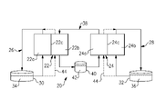
図1は、RFB20を概略的に示す。RFB20は、第1のセル22及び第2のセル24を含む。セル22及び24は、名目上、同一の構成である。セル22及び24は、各々、第1の電極22a及び24aと、第2の電極22b及び24bと、当該電極の間のセパレータ層22c及び24c(電極22aと電極22bとの間の層22c、電極24aと電極24bとの間の層24c)とを含む。例えば、電極22a、22b、24a、及び24bは、カーボン紙またはフェルト等の多孔質のカーボン構造である。セパレータ層はイオン交換膜22c及び24cであり、イオン交換膜22c及び24cは、選択されたイオンが、電極を電気的に絶縁しながら、レドックス反応を完了するために通過することを可能にする。
FIG. 1 shows
第1の循環ループ26は第1のセル22の第1の電極22aと流体接続され、第2の循環ループ28は第2のセル24の第2の電極24bと流体接続される。本明細書に使用されるような「ループ」は、連続的な閉回路の流体通路を指す。第1の循環ループ26及び第2の循環ループ28は、各々の電解質貯蔵タンク30及び32を含み得る。ポリ硫化物電解質溶液34は第1の再循環ループ26内(例えば、タンク30内)に含有され、鉄電解質溶液36は第2の循環ループ28内(すなわち、タンク32内)に含有される。ポリ硫化物電解質溶液34は11.5以上のpHを有し、鉄電解質溶液は3以下のpHを有する。
A
ポリ硫化物電解質溶液34の中のポリ硫化物は、概して、塩基性pH溶液中の硫黄の塩を指す。例えば、塩は、水酸化ナトリウム中のナトリウム塩であり、化学式Na2Sx(式中x=2~5)で表される。一例では、ポリ硫化物電解質溶液34は、1Mの水酸化ナトリウム中の2MのNa2Sxであり得る。鉄電解質溶液36の中の鉄は、概して、酸性溶液中の鉄塩を指す。一例では、鉄電解質溶液36は、1MのNaCl及び0.3MのHCl中の1MのFeClxであり得る。
Polysulfides in
RFB20は、さらに、第1のセル22の第2の電極22bと、第2のセル24の第1の電極24aとに流体接続される第3の循環ループ38を含む。第3の循環ループ38は、電解質貯蔵タンク40を含み得る。第3の循環ループ38は、セル22及び24の両方の反応に関与する仲介電解質溶液42(すなわち、タンク42内にある)を含有する。仲介電解質溶液42は12以上のpHを有する。例えば、仲介電解質溶液42は、キノキサリン、アントラキノン、またはベンゾキノンのうちの少なくとも1つを含む。一例では、仲介電解質溶液42は、1,2-ベンゾキノン-3,5-ジスルホン酸、4,4’-((9,10-アントラキノン-2,6-ジイル)ジオキシ)ジブチラート(2,6-DBEAQ)、1,2-DBEAQ,または1,8-DBEAQのうちの少なくとも1つを含む。他の官能性ヒドロキシル化アントラキノン(例えば、2,6-ジヒドロキシアントラキノン(2,6-DHAQ))も使用され得る。他の有機塩基レドックス対は、ビオロゲン、キノキサリン、またはアロキサジンに基づく分子を含む。また、フェロセン等の有機金属反応剤が使用され得る。一例では、仲介電解質溶液は、1MのNaOH及び1MのNaClの中の0.4MのNaFe(CN)6である。別の例では、仲介電解質溶液は、0.5MのNaOH及び0.5MのNaClの中の0.5Mの2,6-DBEAQである。
ポリ硫化物電解質溶液34は第1のセル22の第1の電極22aを通って循環し、鉄電解質溶液は第2のセル24の第2の電極24bを通って循環する。仲介電解質溶液42は、第1のセル22の第2の電極22b及び第2のセル24の第1の電極24aを通って循環する。第1のセル22内のポリ硫化物電解質溶液34及び仲介電解質溶液42、ならびに第2のセル24内の鉄電解質溶液36及び仲介電解質溶液42は、充電するときに投入電気エネルギーを貯蔵するように及び放電するときに貯蔵された電気エネルギーを放電するように可逆反応するように動作可能である。電気エネルギーは、電極22a、22b、24a、及び24bと電気的に結合される電気回路を通って、セル22及び24に、及びセル22及び24から伝達され得る。
The
以下の方程式は、第1のセル22の反応の例、及び結果として生じる標準水素電極(SHE)に対する標準電極電位(Eo)を実証し、開放セル電圧(OCV)は、本明細書では、2つの電極反応の標準電極電位の差として定義される。
The following equations demonstrate an example
2Na2S2⇔Na2S4+2Na++2e’;Eo=-0.45 vs SHE
[Fe(CN)6]3-+e’⇔[Fe(CN)6]4-;Eo=+0.36 vs SHE
OCV=0.81V
以下の方程式は、第2のセル24の反応の例、及び結果として生じる標準的水素電極(SHE)に対する標準電極電位(Eo)、及び開放セル電圧(OCV)を実証する。
2Na 2 S 2 ⇔ Na 2 S 4 +2Na + +2e'; Eo = -0.45 vs SHE
[Fe(CN) 6 ] 3- + e'⇔ [Fe(CN) 6 ] 4- ;Eo=+0.36 vs SHE
OCV=0.81V
The following equations demonstrate an example of the reaction of the
[Fe(CN)6]4-⇔[Fe(CN)6]3-+e’;Eo=+0.36 vs SHE
2FeCl3+2Na++2e’⇔2FeCl2+2NaCl;Eo=+0.771 vs SHE
OCV=0.41V
正味の反応は下式のとおりである。
[Fe(CN) 6 ] 4− ⇔ [Fe(CN) 6 ] 3− +e′; E o =+0.36 vs SHE
2FeCl 3 +2Na + +2e′≅2FeCl 2 +2NaCl; E o =+0.771 vs SHE
OCV=0.41V
The net reaction is:
2Na2S2+2FeCl3→Na2S4+2FeCl2+2NaCl
OCV=1.218V
上記に説明したように、ポリ硫化物及び鉄電解質溶液は、概して、RFB内で相溶性がない。しかしながら、RFB20内の仲介電解質溶液42は、不相溶性を軽減し、硫化物電解質及び鉄電解質を一緒に使用することを可能にする。例えば、硫黄は鉄溶液にクロスオーバーするのではなく、RFB20内の硫黄は、仲介電解質溶液42にクロスオーバーする。また、鉄は硫黄溶液にクロスーバーするのではなく、RFB20内の鉄は、仲介電解質溶液42にクロスオーバーする。仲介電解質溶液42は、硫黄及び鉄とのより望ましい反応を生じさせるために選択され、それにより、硫黄及び鉄は、容易に、それらの各々の溶液34及び36に回収され及び戻されることができる。
2Na2S2 + 2FeCl3 → Na2S4 + 2FeCl2 +2NaCl
OCV=1.218V
As explained above, polysulfide and iron electrolyte solutions are generally incompatible in RFBs. However, the
例えば、硫黄が第1の電極22aからイオン交換層22cを通って第2の電極22bにおける仲介電解質溶液42にクロスオーバーするとき、硫黄は固体硫黄生成物として沈殿する。鉄が第2の電極24bからイオン交換層24cを通って第1の電極24aにおける仲介電解質溶液42にクロスオーバーするとき、鉄は固体鉄生成物として沈殿する。硫黄及び鉄が沈殿する条件として、仲介電解質溶液42のpHが12以上であることと、標準電極電位が-0.3Vを上回ることとが要求される。約12未満のpHまたは約-0.3V未満の標準電極電位において、硫黄は反応して硫化水素ガスを形成し得、鉄は反応して不溶性酸化鉄を形成し得る。後で下記に説明されるように、固体硫黄生成物及び固体酸化鉄生成物は、容易に、各々、RFBの性能を維持するために、ポリ硫化物電解質溶液34及び鉄電解質溶液36の中に戻るように回収及び混和されることができる。
For example, when sulfur crosses over from the
12以上のpH及び-0.3V以上の標準電極電位に加えて、選択された仲介電解質溶液42は、その還元反応と酸化反応との間で、かなり速い可逆反応速度があり、イオン官能基(例えば、OH-)を有し、仲介剤(intermediator)のクロスオーバーを減らす巨大分子である。仲介電解質溶液42の溶解度は重要ではない。その理由として、仲介電解質溶液42は、常に、約50%の充電状態を維持し、仲介電解質の限定量だけが要求されるためである。(すなわち、当該量は、電池の合計エネルギー容量を判定するものではない)。
In addition to a pH of 12 or higher and a standard electrode potential of −0.3 V or higher, the selected
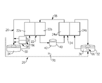
図2は、RFB20のさらなる例を示す。この例では、RFB20は、加えて、1つ以上のフラッシュライン(flush lines)44を含む。フラッシュライン44は、図3に示される電解質獲得方法(ETM)50に従って、固体硫黄生成物及び固体鉄生成物を除去及び回収するために使用され得る。本方法50は、概して、ステップ52及び54を含む。ステップ52において、仲介電解質溶液42は、第1のセルの第2の電極22bから及び第2のセル24の第1の電極24aから空にされる。ステップ54において、ポリ硫化物電解質溶液34は第1のセルの第2の電極22bを通ってフラッシュライン44を介して循環し、及び/または鉄電解質溶液36は第2のセル24の第1の電極24aを通ってフラッシュライン44を介して循環する。固体硫化物生成物は、ポリ硫化物電解質溶液34の中で易溶性のものである。したがって、ポリ硫化物電解質溶液34は、第2の電極22bから固体硫化物生成物を溶解及び除去する。同様に、固体鉄生成物は、鉄電解質溶液36の中で易溶性のものである。したがって、鉄電解質溶液36は、第1の電極24aから固体鉄生成物を溶解及び除去する。
FIG. 2 shows a further example of RFB20. In this example,
いったん固体硫黄生成物及び/または固体鉄生成物が所望のレベルまで除去されると、ポリ硫化物電解質溶液34は第1のループ26に戻るように移送され、鉄電解質溶液36は第2のループ28に戻るように移送される。次に、仲介電解質溶液42は、セル22及び24を通る循環を再開し、RFB20を充電または放電することができる。
Once the solid sulfur products and/or solid iron products have been removed to the desired level, the
図4及び図5は、RFB20のさらなる例を示す。これらの例では、RFB20は、加えて、バイパスライン56と、バイパスライン56内の第3のセル58とを含む。図4では、バイパスライン56及び第3のセル58は第1のループ26内にあり、図5では、バイパスライン56及び第3のセル58は第2のループ28内にある。バイパスライン56及び第3のセル58は、ポリ硫化物電解質溶液34のpHを11.5以上のpHに、または鉄電解質溶液36のpHを3以下のpHに維持するために、図6の方法60に従って使用され得る。
4 and 5 show further examples of
ステップ62において、第3のセル58は、ポリ硫化物電解質溶液34(図4)または鉄電解質溶液36(図5)を電解するため使用される。第3のセル58は、入力電力を使用して、水素ガスを発生するためにポリ硫化物電解質溶液34の電気分解反応、または酸素ガスを発生するために鉄電解質溶液36の電気分解反応を活発にする、電解槽セルである。各々の正味の反応は、以下のとおりである。
At
(ポリ硫化物電解質溶液)
2H2O+2Na2S2→Na2S4+2NaOH+H2(g)
(鉄電解質溶液)
2H2O+4FeCl3→4FeCl2+4HCl+O2(g)
ステップ64において、水素は、鉄電解質溶液36のpHを調整するために鉄電解質溶液36の中に導入されることができる、及び/または酸素ガスは、ポリ硫化物電解質溶液34のpHを調整するためにポリ硫化物電解質溶液34の中に導入されることができる。例えば、水素ガスの導入は、66(図4)に示されるようなタンク32内等で、鉄電解質溶液36中に水素ガスをスパージングすること(泡立てること)を含む。水素は、鉄電解質溶液36に反応し、pHを低下させる。例えば、酸素ガスの導入は、68(図5)に示されるようなタンク30内等で、ポリ硫化物電解質溶液34中に酸素ガスをスパージングすること(泡立てること)を含む。酸素は、ポリ硫化物34に反応し、pHを増加させる。これらの点では、第3のセル58は、第2のループ28(図4)または第1のループ(図5)のいずれかに、ブリードライン70によって接続され得る。
(Polysulfide electrolyte solution)
2H2O + 2Na2S2 → Na2S4 + 2NaOH+H2 ( g)
(iron electrolyte solution)
2H2O+ 4FeCl3 →4FeCl2 + 4HCl + O2 (g)
At
低コストに起因するRFBでの使用において魅力的な追加種は過マンガン酸塩及び硫黄である。しかしながら、低電位の硫黄電解質にクロスオーバーするマンガン酸塩種は還元して不溶性の水酸化マンガンMn(OH)2を形成し、マンガン酸塩電解質にクロスオーバーする硫黄は酸化して固体硫黄金属を形成する。経時的に、硫黄及びマンガン酸塩種の損失、ならびに不溶性硫黄及びマンガン酸塩種からの詰まりは、RFBを動作不可能の状態にするであろう、または、少なくとも、RFBとして使用されるのに往復効率を実現不可能なレベルに低下させるであろう。下記に説明されるように、マンガン酸塩及び硫黄を利用する開示されるRFBは、必ずしも、仲介電解質を要求しない。しかしながら、当該RFBは、上記に説明した同様の回収方策を採用し、RFB内のクロスオーバーに起因する問題を軽減し得る。 Attractive additional species for use in RFBs due to their low cost are permanganate and sulfur. However, manganate species that cross over to the low potential sulfur electrolyte are reduced to form insoluble manganese hydroxide Mn(OH) 2 , and sulfur that crosses over to the manganate electrolyte is oxidized to solid sulfur metal. Form. Over time, loss of sulfur and manganate species and clogging from insoluble sulfur and manganate species will render the RFB inoperable, or at least the It would reduce the round trip efficiency to an unfeasible level. As explained below, the disclosed RFBs utilizing manganate and sulfur do not necessarily require a mediating electrolyte. However, the RFB may employ similar recovery strategies as described above to mitigate problems due to crossovers within the RFB.
RFBのポリ硫化物及びマンガン酸塩の所望の反応は、下式のとおりである。 The desired reaction of the RFB polysulfide and manganate is as follows.
負極:2Na2S2⇔Na2S4+2Na++2e-
Eo=-0.447 vs SHE
正極:2NaMnO4+2Na++2e-⇔2Na2MnO4
Eo=+0.558 vs SHE
正味セル:2Na2S2+2NaMnO4⇔Na2S4+2Na2MnO4
OCV=1.01V
クロスオーバーが固体析出物をもたらす事実は、S(硫黄)及びMn(マンガン)が分離され、それらの元の電解質に戻されることを可能にする。固体が電極内に堆積される場合、(Fe及びS系に関して)上記に説明したETM方法50は、固体種を溶解し、その元の電解質に戻すことができる。さらに、これらの固体が膜内にある場合、両方の電極を同じ電解質に曝すことは、溶解及び回収することを可能にするはずである。この回収機構は、速い(すなわち、1時間未満)ことが予想され、必要に応じて、昇温で行われ、プロセスを速めることができる。最終結果として、電解質平衡を維持することになる。
Negative electrode: 2Na 2 S 2 ⇔ Na 2 S 4 +2Na + +2e -
Eo = -0.447 vs. SHE
Positive electrode: 2NaMnO 4 +2Na + +2e − ⇔ 2Na 2 MnO 4
E o =+0.558 vs SHE
Net cell: 2Na2S2 + 2NaMnO4 < -> Na2S4 + 2Na2MnO4
OCV=1.01V
The fact that crossover results in solid deposits allows S (sulfur) and Mn (manganese) to be separated and returned to their original electrolytes. If a solid is deposited within the electrode, the
例証するために、図7は別の例RFB120を示す。この例のRFB120は、第3の循環ループを含まず、単一の一般的なセル122または一般的なセルのスタックだけを含む。セル122は、第1の電極122aと、第2の電極122bと、第1の電極122aと第2の電極122bとの間にセパレータ層122cとを含む。本開示では、同様の参照数字は同様の要素を指定し、100またはその倍数を付けた適切な数字及び参照数字は、対応する要素の同じ特徴及び利点を組み込むことが理解される修正された要素を指定する。
To illustrate, FIG. 7 shows another
第1の循環ループ26はセル122の第1の電極122aと流体接続され、第2の循環ループ28はセル122の第2の電極122bと流体接続される。ポリ硫化物電解質溶液34は第1の再循環ループ26内(例えば、タンク30内)に含有され、マンガン酸塩電解質溶液136は第2の循環ループ28内(すなわち、タンク32内)に含有される。
The
ETP方法50では、ポリ硫化物電解質溶液34は、(ドレン後に)第2の電極122bを通って送り込まれ、任意の固体S0を還元、溶解、及び再捕捉する。ポリ硫化物電解質溶液34は、沈殿した残りのMnのいずれかを捕捉するために、第1の方向80aにおいて、第1の補助ループ82a内にある双方向フィルタ80を通るように通過する。同様に、ただし異なる時間において、マンガン酸塩電解質溶液136は、(ドレン後に)第1の電極122aを通って送り込まれ、沈殿したMn(OH)2のいずれかを酸化及び溶解する。マンガン酸塩電解質溶液136は、沈殿した残りのSのいずれかを捕捉するために、第2の方向80bに、(ただし、第2の補助ループ82bの一部として)同じ双方向フィルタ80を通るように通過する。双方向フィルタ80は、ポリ硫化物電解質溶液34及びマンガン酸塩電解質溶液136の中で再捕捉される取り除かれた沈殿種の再捕捉を可能にする。
In the
クロスオーバーから生じる固体がタンク30またはタンク32内に集まる場合、これらの固体は、定期的に、タンク30またはタンク32の底部リザーバから除去され得る(固体は、液体ひいてはシンクよりも高い密度を有する)。仮にある場合、このプロセスが多くの場合に行われる必要ではないであろう、完全に自動化される必要はないことが予想される(すなわち、これは、年1回の保守手順の一部であり得る)。
If solids resulting from the crossover collect in
Mnがたくさんの酸化状態をもたらすため、不均化反応の可能性がある。マンガン酸塩がMn(V)O4 3-に不均化を起こす場合、化合物は急速に分解し、MnO2に沈殿するが、強アルカリ性条件下で、この反応は懸念がない(すなわち、pH≧14)。しかしながら、高濃度のNaOHにおいて、以下の反応がゆっくり発生し得る。 There is a possibility of disproportionation reactions because Mn provides many oxidation states. When manganate disproportionates to Mn(V)O 4 3− , the compound decomposes rapidly and precipitates to MnO 2 , but under strongly alkaline conditions this reaction is not a concern (i.e. pH ≧14). However, at high concentrations of NaOH, the following reactions can occur slowly.
4NaMnO4+4NaOH→4Na2MnO4+2H2O+O2
マンガン酸塩(VI)のさらなる還元は発生しない。反応は遅くなる。7.5MのOH-の中の4MのMnO4
-溶液の測定値は、完全に帯電した溶液の保管の1カ月後の80%の容量保持を示す。それにもかかわらず、下記に説明されるもの等の緩和方策が採用されない限り、この反応は永久的な容量損失をもたらすであろう。マンガン対の可逆電位がpH=14におけるO2発生に関するEo(SHEに対して0.401V)よりも157mV高いため、また酸素発生は懸念がある。したがって、O2発生の触媒作用を最小限にするために、正電極材料を選ばなければならない。ポリ硫化物に関する可逆電位が上記のH2発生に関するEoを上回るため、H2発生は懸念がない。
4NaMnO4 +4NaOH→ 4Na2MnO4 + 2H2O + O2
No further reduction of manganate (VI) occurs. reaction slows down. Measurements of a 4 M MnO 4 − solution in 7.5 M OH − show 80% capacity retention after 1 month of storage of the fully charged solution. Nevertheless, this reaction will result in permanent capacity loss unless mitigation measures such as those described below are employed. Oxygen evolution is also a concern because the reversible potential of the manganese pair is 157 mV higher than the E o for O 2 evolution at pH=14 (0.401 V vs SHE). Therefore, positive electrode materials must be chosen to minimize catalysis of O2 evolution. H2 evolution is not a concern because the reversible potential for polysulfides exceeds the above Eo for H2 evolution.
不均化反応から発生する、または正電極の酸素発生反応によって生成される少量のO2は、電解質不均衡をもたらし、RFB内でエネルギー容量がなくなることをもたらす。この場合、正の電解質リザーバ及び負の電解質リザーバの上の気層を接続することにより、O2が負の電解質と反応することを可能にすることによって、O2を消費することができる(この気層は、アノード液の放電を防止するために、N2ブランケットとして維持されるものとする)。 The small amount of O2 generated from the disproportionation reaction or produced by the oxygen evolution reaction at the positive electrode leads to electrolyte imbalance and loss of energy capacity within the RFB. In this case, connecting the gas layers above the positive and negative electrolyte reservoirs allows O2 to be consumed by allowing it to react with the negative electrolyte (this The gas layer shall be maintained as a N2 blanket to prevent discharge of the anolyte).
O2+2H2O+4Na2S2⇔2Na2S4+4NaOH
この反応及び上記の正味は、両方の電解質の放電であるが、それは、電解質が一定組成に維持されることをもたらす。これらの反応の別の結果は、ポリ硫化物電解質溶液34のpHの増加及びマンガン酸塩電解質溶液136の減少であるであろう、ただし、水濃度及び[OH-]の変化は、膜を通る拡散によって弱まるはずである。これは事実と異なる場合、随意に、第2のステップ64を使用して、マンガン電解質の分解を調整すること(すなわち、O2ガスをポリ硫化物中に導入する(O2ガスは既にポリ硫化物中に含まれている))だけを除いて、pH調整セル及び方法60のFe及びSに関する上記に説明したプロセスを利用することができる。
O2 + 2H2O + 4Na2S2 ⇔ 2Na2S4 + 4NaOH
Although this reaction and the net above is a discharge of both electrolytes, it results in the electrolytes being maintained at a constant composition. Another consequence of these reactions would be an increase in the pH of the
特徴の組み合わせが示された例に示されているが、それらの全てが、本開示の様々な実施形態の利点を実現するために組み合わせられる必要があるわけではない。言い換えれば、本開示の実施形態に従って設計されたシステムは、必ずしも、図の任意の1つに示される特徴の全て、または図に概略的に示される部分の全てを含むわけではないであろう。さらに、一つの例示的実施形態の選択された特徴は、他の例示的実施形態の選択された特徴と組み合わせられ得る。 Although combinations of features are shown in the illustrated examples, not all of them need be combined to realize the benefits of various embodiments of the present disclosure. In other words, a system designed in accordance with embodiments of the present disclosure would not necessarily include all of the features shown in any one of the figures or all of the portions shown schematically in the figures. Moreover, selected features of one exemplary embodiment may be combined with selected features of other exemplary embodiments.
前述の説明は、本質的に、限定的よりはむしろ例示的である。開示された例に対する変形例及び修正は、必ずしも本開示から逸脱することなく、当業者に明白になり得る。本開示に与えられた法的保護の範囲は、以下の「特許請求の範囲」だけを検討することによって判定されることができる。 The foregoing description is exemplary rather than restrictive in nature. Variations and modifications to the disclosed examples may become apparent to those skilled in the art without necessarily departing from this disclosure. The scope of legal protection given to this disclosure can be determined by studying only the following claims.
Claims (13)
第1のセル及び第2のセルであって、前記セルのそれぞれが、第1の電極及び第2の電極と、前記第1の電極と前記第2の電極との間に配列されるセパレータ層とを有する、第1のセル及び第2のセルと、
前記第1のセルの前記第1の電極と流体接続される第1の循環ループと、
前記第1の循環ループ内に収容される11.5以上のpHを有する硫化物電解質溶液と、
前記第2のセルの前記第2の電極と流体接続される第2の循環ループと、
前記第2の循環ループ内に収容される3以下のpHを有する鉄電解質溶液と、
前記第1のセルの前記第2の電極と、前記第2のセルの前記第1の電極とに流体接続される第3の循環ループと、
前記第3の循環ループ内に含有される仲介電解質溶液と、を含み、
前記第1のセル内の前記硫化物電解質溶液及び前記仲介電解質溶液、ならびに前記第2のセル内の前記鉄電解質溶液及び前記仲介電解質溶液は、充電するときに投入電気エネルギーを貯蔵し、かつ放電するときに貯蔵された前記電気エネルギーを放電するように可逆反応するように動作可能であり、
前記仲介電解質溶液は、キノキサリン、アントラキノン、またはベンゾキノンのうちの少なくとも1つを有しており、
前記仲介電解質溶液は12以上のpHを有し、
前記第1のセルは-0.3Vよりも大きい標準電極電位を有する、レドックスフロー電池。 A redox flow battery,
a first cell and a second cell, each of said cells comprising a first electrode and a second electrode and a separator layer arranged between said first electrode and said second electrode a first cell and a second cell having
a first circulation loop fluidly connected to the first electrode of the first cell;
a sulfide electrolyte solution having a pH of 11.5 or greater contained within the first circulation loop;
a second circulation loop fluidly connected to the second electrode of the second cell;
an iron electrolyte solution having a pH of 3 or less contained within the second circulation loop;
a third circulation loop fluidly connected to the second electrode of the first cell and the first electrode of the second cell;
a mediating electrolyte solution contained within the third circulation loop;
The sulfide electrolyte solution and the intermediary electrolyte solution in the first cell and the iron electrolyte solution and the intermediary electrolyte solution in the second cell store input electrical energy when charging and discharging. operable to reversibly react to discharge said stored electrical energy when
the mediating electrolyte solution comprises at least one of quinoxaline, anthraquinone, or benzoquinone;
the mediating electrolyte solution has a pH of 12 or greater;
A redox flow battery, wherein the first cell has a standard electrode potential greater than -0.3V.
前記第3のセルは、水素ガスを生成するために、前記硫化物電解質溶液を電解するように動作可能である、請求項1に記載のレドックスフロー電池。 the first circulation loop includes a bypass line and a third cell within the bypass line;
3. The redox flow battery of claim 1, wherein said third cell is operable to electrolyze said sulfide electrolyte solution to produce hydrogen gas.
前記第3のセルは、酸素ガスを生成するために、前記鉄電解質溶液を電解するように動作可能である、請求項1に記載のレドックスフロー電池。 the second circulation loop includes a bypass line and a third cell within the bypass line;
3. The redox flow battery of claim 1, wherein said third cell is operable to electrolyze said iron electrolyte solution to produce oxygen gas.
充電するときに投入電気エネルギーを貯蔵し、放電するときに貯蔵された前記電気エネルギーを放電するために、レドックスフロー電池の第1のセル及び第2のセルを使用することであって、
前記セルのそれぞれは、第1の電極と第2の電極との間に配列されるイオン交換層を有し、
前記使用することは、
前記第1のセルの前記第1の電極と流体接続する第1の循環ループを通して、11.5以上のpHの硫化物電解質溶液を循環させることと、
前記第2のセルの前記第2の電極と流体接続する第2の循環ループを通して、3以下のpHの鉄電解質溶液を循環させることと、
前記第1のセルの前記第2の電極と、前記第2のセルの前記第1の電極とに流体接続する第3の循環ループを通して、仲介電解質溶液を循環させることと、を含み、
前記第1のセルの前記第1の電極内の前記硫化物電解質溶液から前記イオン交換層を通って浸透した硫黄は、前記第1のセルの前記第2の電極内に固体硫化物生成物として沈殿し、前記第2のセルの前記第2の電極内の前記鉄電解質溶液から前記イオン交換層を通って浸透した鉄は、前記第2のセルの前記第1の電極内に固体鉄生成物として沈殿する、
第1のセル及び第2のセルを使用することと、
前記第1のセルの前記第2の電極、または前記第2のセルの前記第1の電極のいずれかから、前記仲介電解質溶液を空にすることと、
前記固体硫化物生成物を前記硫化物電解質溶液に回収すること、または前記固体鉄生成物を前記鉄電解質溶液に回収すること、のいずれかを行うことであって、それぞれ、
前記第1の循環ループから前記第1のセルの前記第2の電極を通して、前記硫化物電解質溶液の少なくとも一部を循環させて、前記第2の電極から前記固体硫化物生成物を溶解させ、それにより除去し、次に、溶解した前記固体硫化物生成物とともに前記硫化物電解質溶液を、前記第1の循環ループに戻すように移送することによって回収すること、または、
前記第2の循環ループから前記第2のセルの前記第1の電極を通して、前記鉄電解質溶液の少なくとも一部を循環させて、前記第1の電極から前記固体鉄生成物を溶解させ、それにより除去し、次に、溶解した前記固体鉄生成物とともに前記鉄電解質溶液を、前記第2の循環ループに戻すように移送することによって回収すること、のいずれかを行うことと、
を備え、
前記第1のセル内の前記硫化物電解質溶液及び前記仲介電解質溶液、ならびに前記第2のセル内の前記鉄電解質溶液及び前記仲介電解質溶液は、充電するときに投入電気エネルギーを貯蔵し、かつ放電するときに貯蔵された前記電気エネルギーを放電するように可逆反応するように動作可能であり、
前記仲介電解質溶液は、キノキサリン、アントラキノン、またはベンゾキノンのうちの少なくとも1つを有しており、
前記仲介電解質溶液は12以上のpHを有し、
前記第1のセルは-0.3Vよりも大きい標準電極電位を有することを特徴とする、方法。 A method for a redox flow battery, comprising:
Using a first cell and a second cell of a redox flow battery to store input electrical energy when charging and to discharge said stored electrical energy when discharging, comprising:
each of said cells having an ion exchange layer arranged between a first electrode and a second electrode;
said using
circulating a sulfide electrolyte solution at a pH of 11.5 or greater through a first circulation loop in fluid communication with the first electrode of the first cell;
circulating an iron electrolyte solution at a pH of 3 or less through a second circulation loop in fluid communication with the second electrode of the second cell;
circulating a mediating electrolyte solution through a third circulation loop fluidly connecting the second electrode of the first cell and the first electrode of the second cell;
Sulfur that permeates through the ion exchange layer from the sulfide electrolyte solution in the first electrode of the first cell is deposited in the second electrode of the first cell as solid sulfide products. Iron that precipitates and percolates through the ion exchange layer from the iron electrolyte solution in the second electrode of the second cell forms a solid iron product in the first electrode of the second cell. precipitate as
using a first cell and a second cell;
emptying the intermediate electrolyte solution from either the second electrode of the first cell or the first electrode of the second cell;
recovering the solid sulfide products in the sulfide electrolyte solution or recovering the solid iron products in the iron electrolyte solution, respectively,
circulating at least a portion of the sulfide electrolyte solution from the first circulation loop through the second electrode of the first cell to dissolve the solid sulfide products from the second electrode; thereby removing and then recovering the sulfide electrolyte solution with the dissolved solid sulfide product by transferring it back to the first circulation loop; or
circulating at least a portion of the iron electrolyte solution from the second circulation loop through the first electrode of the second cell to dissolve the solid iron products from the first electrode, thereby removing and then recovering the iron electrolyte solution with the dissolved solid iron product by transferring it back into the second circulation loop;
with
The sulfide electrolyte solution and the intermediary electrolyte solution in the first cell and the iron electrolyte solution and the intermediary electrolyte solution in the second cell store input electrical energy when charging and discharging. operable to reversibly react to discharge said stored electrical energy when
the mediating electrolyte solution comprises at least one of quinoxaline, anthraquinone, or benzoquinone;
the mediating electrolyte solution has a pH of 12 or greater;
A method, wherein said first cell has a standard electrode potential greater than -0.3V.
充電するときに投入電気エネルギーを貯蔵し、放電するときに貯蔵された前記電気エネルギーを放電するために、レドックスフロー電池の第1のセル及び第2のセルを使用することであって、
前記セルのそれぞれは、第1の電極と第2の電極との間に配列されるセパレータ層を有し、
前記使用することは、
前記第1のセルの前記第1の電極と流体接続する第1の循環ループを通して、11.5以上のpHの硫化物電解質溶液を循環させることと、
前記第2のセルの前記第2の電極と流体接続する第2の循環ループを通して、3以下のpHの鉄電解質溶液を循環させることと、
前記第1のセルの前記第2の電極と、前記第2のセルの前記第1の電極と、に流体接続する第3の循環ループを通して、仲介電解質溶液を循環させることと、を含む、
第1のセル及び第2のセルを使用することと、
水素ガスを生成するように前記硫化物電解質溶液を電解する、または、酸素ガスを生成するように前記鉄電解質溶液を電解する、のいずれかを行うための第3のセルを使用することと、
前記硫化物電解質溶液のpHを11.5以上のpHに維持する、または、前記鉄電解質溶液のpHを3以下のpHに維持することであって、それぞれ、
前記硫化物電解質溶液のpHを調整するために前記酸素ガスを前記硫化物電解質溶液中に導入することによって維持する、または
前記鉄電解質溶液のpHを調整するために前記水素ガスを前記鉄電解質溶液中に導入することによって維持することと、
を備え、
前記第1のセル内の前記硫化物電解質溶液及び前記仲介電解質溶液、ならびに前記第2のセル内の前記鉄電解質溶液及び前記仲介電解質溶液は、充電するときに投入電気エネルギーを貯蔵し、かつ放電するときに貯蔵された前記電気エネルギーを放電するように可逆反応するように動作可能であり、
前記仲介電解質溶液は、キノキサリン、アントラキノン、またはベンゾキノンのうちの少なくとも1つを有しており、
前記仲介電解質溶液は12以上のpHを有し、
前記第1のセルは-0.3Vよりも大きい標準電極電位を有することを特徴とする、方法。 A method for a redox flow battery, comprising:
Using a first cell and a second cell of a redox flow battery to store input electrical energy when charging and to discharge said stored electrical energy when discharging, comprising:
each of the cells having a separator layer arranged between a first electrode and a second electrode;
said using
circulating a sulfide electrolyte solution at a pH of 11.5 or greater through a first circulation loop in fluid communication with the first electrode of the first cell;
circulating an iron electrolyte solution at a pH of 3 or less through a second circulation loop in fluid communication with the second electrode of the second cell;
circulating a mediating electrolyte solution through a third circulation loop fluidly connecting the second electrode of the first cell and the first electrode of the second cell;
using a first cell and a second cell;
using a third cell to either electrolyze the sulfide electrolyte solution to produce hydrogen gas or electrolyze the iron electrolyte solution to produce oxygen gas;
maintaining the pH of the sulfide electrolyte solution at a pH of 11.5 or higher, or maintaining the pH of the iron electrolyte solution at a pH of 3 or lower, respectively,
maintain by introducing the oxygen gas into the sulfide electrolyte solution to adjust the pH of the sulfide electrolyte solution; or the hydrogen gas to adjust the pH of the iron electrolyte solution. maintaining by introducing into
with
The sulfide electrolyte solution and the intermediary electrolyte solution in the first cell and the iron electrolyte solution and the intermediary electrolyte solution in the second cell store input electrical energy when charging and discharging. operable to reversibly react to discharge said stored electrical energy when
the mediating electrolyte solution comprises at least one of quinoxaline, anthraquinone, or benzoquinone;
the mediating electrolyte solution has a pH of 12 or greater;
A method, wherein said first cell has a standard electrode potential greater than -0.3V.
Applications Claiming Priority (2)
| Application Number | Priority Date | Filing Date | Title |
|---|---|---|---|
| US16/052,727 | 2018-08-02 | ||
| US16/052,727 US11056698B2 (en) | 2018-08-02 | 2018-08-02 | Redox flow battery with electrolyte balancing and compatibility enabling features |
Publications (2)
| Publication Number | Publication Date |
|---|---|
| JP2020021732A JP2020021732A (en) | 2020-02-06 |
| JP7201552B2 true JP7201552B2 (en) | 2023-01-10 |
Family
ID=67439077
Family Applications (1)
| Application Number | Title | Priority Date | Filing Date |
|---|---|---|---|
| JP2019140397A Active JP7201552B2 (en) | 2018-08-02 | 2019-07-31 | REDOX FLOW BATTERY AND METHOD FOR REDOX FLOW BATTERY |
Country Status (4)
| Country | Link |
|---|---|
| US (2) | US11056698B2 (en) |
| EP (1) | EP3605696B1 (en) |
| JP (1) | JP7201552B2 (en) |
| DK (1) | DK3605696T3 (en) |
Families Citing this family (17)
| Publication number | Priority date | Publication date | Assignee | Title |
|---|---|---|---|---|
| MA53343A (en) | 2018-07-27 | 2022-03-23 | Form Energy Inc | NEGATIVE ELECTRODES FOR ELECTROCHEMICAL CELLS |
| CN111261917B (en) * | 2018-11-30 | 2021-06-22 | 中国科学院大连化学物理研究所 | Application of soluble manganate as additive in cathode electrolyte of zinc-nickel flow battery |
| US12294086B2 (en) | 2019-07-26 | 2025-05-06 | Form Energy, Inc. | Low cost metal electrodes |
| US11637341B1 (en) * | 2020-02-14 | 2023-04-25 | Massachusetts Institute Of Technology | Multi-phase electrochemical cells and related systems and methods |
| CN114105893B (en) * | 2020-08-28 | 2024-10-18 | 西湖大学 | Amino acid derivative-based electrolytes and their applications in flow batteries |
| KR102486285B1 (en) * | 2020-10-08 | 2023-01-10 | 탑에코에너지주식회사 | Redox flow battery |
| DE102020130693A1 (en) * | 2020-11-20 | 2022-05-25 | Schaeffler Technologies AG & Co. KG | Component for an electrochemical cell, as well as a redox flow cell, fuel cell and electrolyser |
| US11271226B1 (en) * | 2020-12-11 | 2022-03-08 | Raytheon Technologies Corporation | Redox flow battery with improved efficiency |
| CA3198734A1 (en) * | 2020-12-24 | 2022-06-30 | Peter Geigle | Aqueous energy storage system for redox flow batteries |
| US12288912B2 (en) | 2020-12-31 | 2025-04-29 | Uop Llc | Redox flow battery with a balancing cell |
| US11664518B2 (en) * | 2021-05-21 | 2023-05-30 | Raytheon Technologies Corporation | Alkaline manganese redox flow battery with inhibitor |
| US12206144B2 (en) * | 2022-03-25 | 2025-01-21 | The Chinese University Of Hong Kong | Polysulfide-based aqueous redox flow battery with soluble organic catalyst |
| EP4523270A4 (en) | 2022-05-09 | 2026-04-22 | Lockheed Martin Energy Llc | RIVER BATTERY WITH A DYNAMIC FLUID NETWORK |
| CN115000480B (en) * | 2022-07-28 | 2024-10-22 | 长沙理工大学 | High-energy-density alkaline iron-sulfur flow battery and preparation method thereof |
| CN115275293A (en) * | 2022-08-12 | 2022-11-01 | 北京九州恒盛电力科技有限公司 | Flow battery and control method thereof |
| CN118412509B (en) * | 2024-05-27 | 2025-02-07 | 安徽恒焺储能科技有限公司 | Acid-base amphoteric iron-sulfur hybrid flow battery and preparation method thereof |
| EP4730449A1 (en) * | 2024-10-17 | 2026-04-22 | Centre National de la Recherche Scientifique | Redox flow battery |
Family Cites Families (205)
| Publication number | Priority date | Publication date | Assignee | Title |
|---|---|---|---|---|
| NL261579A (en) | 1960-02-23 | |||
| BE603874A (en) | 1960-05-17 | |||
| DE2109034C3 (en) | 1971-02-25 | 1978-10-12 | Siemens Ag, 1000 Berlin Und 8000 Muenchen | Battery from a plurality of cells |
| US4053684A (en) | 1972-10-10 | 1977-10-11 | Gel, Inc. | Method of operating a fuel cell |
| US4124478A (en) | 1977-02-07 | 1978-11-07 | Tsien Hsue C | Thin sheet apparatus and a fluid flow device |
| JPS5929786B2 (en) | 1977-07-14 | 1984-07-23 | 松下電工株式会社 | Manufacturing method of solar collector |
| US4180623A (en) | 1977-12-19 | 1979-12-25 | Lockheed Missiles & Space Company, Inc. | Electrically rechargeable battery |
| CH642407A5 (en) | 1980-03-05 | 1984-04-13 | Grob & Co Ag | FABRIC. |
| US4407902A (en) | 1980-12-08 | 1983-10-04 | Ford Motor Company | Chemically regenerable redox fuel cell and method of operating the same |
| JPS61173468A (en) | 1985-01-28 | 1986-08-05 | Mitsui Eng & Shipbuild Co Ltd | electrolytic or battery equipment |
| US4786567A (en) | 1986-02-11 | 1988-11-22 | Unisearch Limited | All-vanadium redox battery |
| JPS63213261A (en) | 1987-02-27 | 1988-09-06 | Nkk Corp | Electrolyte flow type battery |
| JPH01146267A (en) | 1987-12-03 | 1989-06-08 | Chiyoda Corp | Operation of redox-flow cell |
| WO1989005528A1 (en) | 1987-12-10 | 1989-06-15 | Unisearch Limited | Vanadium charging cell and vanadium dual battery system |
| WO1989005363A1 (en) | 1987-12-10 | 1989-06-15 | Unisearch Limited | Vanadium compound dissolution processes |
| WO1990003666A1 (en) | 1988-09-23 | 1990-04-05 | Unisearch Limited | State of charge of redox cell |
| JP2920230B2 (en) | 1988-11-30 | 1999-07-19 | 東洋紡績株式会社 | Redox flow battery |
| JP2815112B2 (en) | 1989-01-23 | 1998-10-27 | 住友電気工業株式会社 | Electrolyte recycling secondary battery |
| JPH0799688B2 (en) | 1990-12-26 | 1995-10-25 | トヨタ自動車株式会社 | Zinc bromine battery |
| US5188911A (en) | 1991-02-25 | 1993-02-23 | Magnavox Electronic Systems Company | Tapered manifold for batteries requiring forced electrolyte flow |
| US5318865A (en) | 1991-06-06 | 1994-06-07 | Director-General, Agency Of Industrial Science And Technology | Redox battery |
| US5270132A (en) | 1991-12-26 | 1993-12-14 | International Fuel Cells Corporation | Minimized corrosion fuel cell device and a method of making the same |
| US5298341A (en) | 1992-08-20 | 1994-03-29 | Cerramatec, Inc. | Multiple stack ion conducting devices |
| DE69310529T2 (en) * | 1992-10-14 | 1997-11-06 | Nat Power Plc | ELECTROCHEMICAL ENERGY STORAGE AND POWER SUPPLY METHOD USING AN IRON-SULFUR COUPLE |
| US5496659A (en) | 1992-10-14 | 1996-03-05 | National Power Plc | Electrochemical apparatus for energy storage and/or power delivery comprising multi-compartment cells |
| US5830603A (en) | 1993-09-03 | 1998-11-03 | Sumitomo Electric Industries, Ltd. | Separator film for a storage battery |
| JP3193991B2 (en) | 1993-12-24 | 2001-07-30 | 経済産業省産業技術総合研究所長 | Electrolyte flow battery |
| US5612148A (en) * | 1994-04-13 | 1997-03-18 | National Power Plc | Process for energy storage and/or power delivery with means for restoring electrolyte balance |
| US6309532B1 (en) | 1994-05-20 | 2001-10-30 | Regents Of The University Of California | Method and apparatus for capacitive deionization and electrochemical purification and regeneration of electrodes |
| JP3560181B2 (en) | 1995-04-13 | 2004-09-02 | 東洋紡績株式会社 | Electrode material for liquid flow type electrolytic cell |
| NZ306364A (en) | 1995-05-03 | 1999-04-29 | Unisearch Ltd | High energy density vanadium electrolyte solutions, preparation thereof and redox cells and batteries containing the electrolyte solution |
| US6167301A (en) | 1995-08-29 | 2000-12-26 | Flower; Ronald J. | Iontophoretic drug delivery device having high-efficiency DC-to-DC energy conversion circuit |
| JPH09101286A (en) | 1995-10-04 | 1997-04-15 | Kashimakita Kyodo Hatsuden Kk | Method and instrument for measuring atomicity and concentration of vanadium ion of electrolyte for vanadium redox flow battery |
| JP3505918B2 (en) | 1996-06-19 | 2004-03-15 | 住友電気工業株式会社 | Redox flow battery |
| DE19624883C1 (en) | 1996-06-21 | 1997-07-03 | Pauling Hans Juergen | Making a vehicle battery safe for servicing or after accident |
| JP3098961B2 (en) | 1996-07-24 | 2000-10-16 | 住友電気工業株式会社 | Redox flow battery and method of operating the same |
| US6007933A (en) | 1998-04-27 | 1999-12-28 | Plug Power, L.L.C. | Fuel cell assembly unit for promoting fluid service and electrical conductivity |
| JP2994337B1 (en) | 1998-07-10 | 1999-12-27 | 住友電気工業株式会社 | Method for regenerating electrolyte solution for all vanadium redox flow batteries |
| JP4318771B2 (en) | 1998-11-06 | 2009-08-26 | 本田技研工業株式会社 | Fuel cell stack |
| CA2357928A1 (en) | 1998-12-30 | 2000-07-13 | Ballard Power Systems Inc. | Fuel cell fluid flow field plate and methods of making fuel cell flow field plates |
| PT1192680E (en) | 1999-07-02 | 2004-04-30 | Regenesys Tech Ltd | ELECTROLYTE RE-BALANCE SYSTEM |
| DK1186069T3 (en) | 2000-03-31 | 2003-10-27 | Squirrel Holdings Ltd | Redox flow-through battery and method for operating it |
| US6476583B2 (en) | 2000-07-21 | 2002-11-05 | Jomahip, Llc | Automatic battery charging system for a battery back-up DC power supply |
| KR20030034146A (en) | 2000-08-16 | 2003-05-01 | 스쿼럴 홀딩스 리미티드 | Vanadium electrolyte preparation using asymmetric vanadium reduction cells and use of an asymmetric vanadium reduction cell for rebalancing the state of charge of the electrolytes of an operating vanadium redox battery |
| JP2003079070A (en) | 2000-09-28 | 2003-03-14 | Kansai Electric Power Co Inc:The | Electric power storage system |
| JP2002175822A (en) | 2000-12-07 | 2002-06-21 | Sumitomo Electric Ind Ltd | Redox flow battery and method of operating the same |
| US20020076582A1 (en) | 2000-12-20 | 2002-06-20 | Reiser Carl A. | Procedure for starting up a fuel cell system using a fuel purge |
| US6472095B2 (en) | 2000-12-29 | 2002-10-29 | Utc Fuel Cells, Llc | Hybrid fuel cell reactant flow fields |
| US6628085B2 (en) | 2001-01-17 | 2003-09-30 | Tai-Her Yang | Limit voltage circuit using light emitting diodes as thermal-loss reducing impedances, especially for matching a saturation voltage of rechargeable cells during charging |
| GB2372143B (en) | 2001-02-12 | 2003-04-09 | Morgan Crucible Co | Flow field plate geometries for a fuel cell, including for a polymer electrolyte fuel cell |
| US6905797B2 (en) | 2001-04-12 | 2005-06-14 | Squirrel Holdings Ltd. | Porous mat electrodes for electrochemical reactor having electrolyte solution distribution channels |
| JP2002329522A (en) | 2001-05-01 | 2002-11-15 | Sumitomo Electric Ind Ltd | Secondary battery and method of operating the same |
| US6884530B2 (en) | 2001-05-31 | 2005-04-26 | Sfc, Smart Fuel Cell Ag | Method of improving the performance of a direct feed fuel cell |
| JP3897544B2 (en) | 2001-06-07 | 2007-03-28 | 住友電気工業株式会社 | Redox flow battery electrolyte and redox flow battery |
| JP3657538B2 (en) | 2001-06-12 | 2005-06-08 | 住友電気工業株式会社 | Cell stack for redox flow battery |
| JP2002367658A (en) | 2001-06-12 | 2002-12-20 | Sumitomo Electric Ind Ltd | Cell frame for redox flow battery and redox flow battery |
| ITVA20010019A1 (en) | 2001-06-28 | 2002-12-28 | Chemieco S R L | REDOX CELL WITH NON-SELECTIVE IONIC SEPARATOR |
| US6828055B2 (en) | 2001-07-27 | 2004-12-07 | Hewlett-Packard Development Company, L.P. | Bipolar plates and end plates for fuel cells and methods for making the same |
| JP2003052132A (en) | 2001-08-03 | 2003-02-21 | Sumitomo Electric Ind Ltd | How to operate the power supply system |
| AU2002367842A1 (en) | 2001-10-22 | 2003-11-11 | The C And M Group, Llc | Mediated electrochemical oxidation of organic waste materials |
| GB2382455B (en) | 2001-11-07 | 2004-10-13 | Intelligent Energy Ltd | Fuel cell fluid flow field plates |
| JP2003157883A (en) | 2001-11-21 | 2003-05-30 | Sumitomo Electric Ind Ltd | Method for regenerating electrolyte for vanadium redox battery |
| US20040028989A1 (en) | 2001-12-11 | 2004-02-12 | Sun Hoi-Cheong Steve | Electrochemical device with adjustable-area electrodes using a hydrogen peroxide catholyte |
| DE10297626B4 (en) | 2002-01-04 | 2013-04-18 | Utc Fuel Cells, Llc | A method of starting up a fuel cell system having an anode exhaust gas recycle loop |
| US6686084B2 (en) | 2002-01-04 | 2004-02-03 | Hybrid Power Generation Systems, Llc | Gas block mechanism for water removal in fuel cells |
| US6713206B2 (en) | 2002-01-14 | 2004-03-30 | Board Of Trustees Of University Of Illinois | Electrochemical cells comprising laminar flow induced dynamic conducting interfaces, electronic devices comprising such cells, and methods employing same |
| JP3838107B2 (en) | 2002-01-21 | 2006-10-25 | 三菱マテリアル株式会社 | Separator, separator manufacturing method, and polymer electrolyte fuel cell |
| JP2003303611A (en) | 2002-04-10 | 2003-10-24 | Sumitomo Electric Ind Ltd | How to operate a redox flow battery |
| US7687181B2 (en) | 2002-04-23 | 2010-03-30 | Protonex Technology Corporation | Channel-based electrochemical cassettes |
| US7105245B2 (en) | 2002-07-03 | 2006-09-12 | Neah Power Systems, Inc. | Fluid cell system reactant supply and effluent storage cartridges |
| GB2390738B (en) | 2002-07-09 | 2005-05-11 | Intelligent Energy Ltd | Fuel cell direct water injection |
| WO2004025755A2 (en) | 2002-09-12 | 2004-03-25 | Metallic Power, Inc. | Methods and devices for controlling flow and particle fluidization in a fuel cell |
| US6989205B2 (en) | 2002-10-31 | 2006-01-24 | Motorola, Inc. | Hydrophilic side-chain polymer electrolyte membranes |
| US20040151960A1 (en) | 2003-01-31 | 2004-08-05 | Rock Jeffrey Allan | Flow restrictors in fuel cell flow-field |
| WO2004071967A1 (en) | 2003-02-12 | 2004-08-26 | The C & M Group, Llc | Mediated electrochemical oxidation of animal waste materials |
| WO2004079849A1 (en) | 2003-03-04 | 2004-09-16 | Squirrel Holdings Ltd. | Multi voltage tap redox flow battery composed of stacked cell modules of adjustable cell area |
| AU2003901763A0 (en) | 2003-04-14 | 2003-05-01 | Michael Kazacos | Novel bromide redox flow cells and batteries |
| US7855015B1 (en) | 2003-04-17 | 2010-12-21 | University Of South Florida | Aluminum and solid alkali peroxide galvanic cell |
| US7632583B2 (en) | 2003-05-06 | 2009-12-15 | Ballard Power Systems Inc. | Apparatus for improving the performance of a fuel cell electric power system |
| US6984464B2 (en) | 2003-08-06 | 2006-01-10 | Utc Fuel Cells, Llc | Hydrogen passivation shut down system for a fuel cell power plant |
| US8142950B2 (en) | 2003-08-06 | 2012-03-27 | Utc Power Corporation | Hydrogen passivation shut down system for a fuel cell power plant |
| US6991864B2 (en) | 2003-09-23 | 2006-01-31 | Utc Fuel Cells, Llc | Storage of fuel cell energy during startup and shutdown |
| US7041405B2 (en) | 2003-10-07 | 2006-05-09 | Utc Fuel Cells, Llc | Fuel cell voltage control |
| US7923172B2 (en) | 2003-11-14 | 2011-04-12 | Basf Fuel Cell Gmbh | Structures for gas diffusion materials and methods for their fabrication |
| AU2003304610A1 (en) | 2003-12-12 | 2005-06-29 | Lg Electronics Inc. | Bipolar plate of fuel cell |
| US20050136301A1 (en) | 2003-12-19 | 2005-06-23 | Ballard Power Systems Inc. | Monitoring fuel cells using RFID devices |
| US20050142407A1 (en) | 2003-12-26 | 2005-06-30 | Fuller Thomas F. | Start up cascaded fuel cell stack |
| US8277964B2 (en) | 2004-01-15 | 2012-10-02 | Jd Holding Inc. | System and method for optimizing efficiency and power output from a vanadium redox battery energy storage system |
| JP2005228645A (en) | 2004-02-13 | 2005-08-25 | Sumitomo Electric Ind Ltd | Retaining structure of redox flow battery cell, battery, and electrode |
| US7309540B2 (en) | 2004-05-21 | 2007-12-18 | Sarnoff Corporation | Electrical power source designs and components |
| WO2006076031A2 (en) | 2004-05-22 | 2006-07-20 | Foster-Miller, Inc. | Solid polymer electrolyte membranes |
| KR20060016399A (en) | 2004-08-17 | 2006-02-22 | 현대모비스 주식회사 | Separation plate of fuel cell |
| US7267908B2 (en) | 2004-08-30 | 2007-09-11 | Toyota Technical Center Usa, Inc. | In cycling stability of Li-ion battery with molten salt electrolyte |
| US7396440B2 (en) | 2004-11-19 | 2008-07-08 | Steven Amendola | Load leveling and electrolysis system |
| JP2006156029A (en) | 2004-11-26 | 2006-06-15 | Kansai Electric Power Co Inc:The | Carbon electrode material for vanadium redox flow battery |
| US7569294B2 (en) | 2004-12-23 | 2009-08-04 | Air Products And Chemicals, Inc. | Modular portable battery charging system using hydrogen fuel cells |
| JP2006313691A (en) | 2005-05-09 | 2006-11-16 | Sumitomo Electric Ind Ltd | Redox flow battery system |
| WO2006138611A2 (en) | 2005-06-16 | 2006-12-28 | Trustees Of Boston University | Waste to hydrogen conversion process and related apparatus |
| DK1905117T3 (en) | 2005-06-20 | 2019-08-19 | Newsouth Innovations Pty Ltd | IMPROVED PERFLUORATED MEMBRANES AND IMPROVED ELECTROLYTS FOR REDOX CELLS AND BATTERIES |
| CN101366130B (en) | 2005-12-28 | 2011-12-28 | Utc电力公司 | Fuel cell flow field channels with partially closed ends |
| JP2007188729A (en) | 2006-01-12 | 2007-07-26 | Sumitomo Electric Ind Ltd | Regeneration method of vanadium redox flow battery |
| KR100718113B1 (en) | 2006-01-27 | 2007-05-15 | 삼성에스디아이 주식회사 | Fuel cell bipolar plates and fuel cells |
| CN1845368A (en) | 2006-03-10 | 2006-10-11 | 清华大学深圳研究生院 | Current collection plate for all vanadium redox flow battery |
| US8062801B2 (en) | 2006-08-31 | 2011-11-22 | Utc Power Corporation | Avoiding coolant slump into reactant fields during PEM fuel cell shutdown |
| US8157981B2 (en) | 2006-11-22 | 2012-04-17 | Strategic Resource Optimization, LLC | Electrolytic system and method for enhanced release and deposition of sub-surface and surface components |
| JP2008166164A (en) | 2006-12-28 | 2008-07-17 | Toyota Motor Corp | FUEL CELL SYSTEM AND CONTROL METHOD FOR FUEL CELL SYSTEM |
| GB0701449D0 (en) | 2007-01-26 | 2007-03-07 | Secr Defence | Anion Exchange Membranes |
| US7855005B2 (en) | 2007-02-12 | 2010-12-21 | Deeya Energy, Inc. | Apparatus and methods of determination of state of charge in a redox flow battery |
| US8551667B2 (en) | 2007-04-17 | 2013-10-08 | Ini Power Systems, Inc. | Hydrogel barrier for fuel cells |
| EP1986264A1 (en) | 2007-04-26 | 2008-10-29 | Technische Universität München | System for generating electrical energy comprising an electrochemical reformer and a fuel cell |
| CN202144772U (en) | 2007-06-07 | 2012-02-15 | 韦福普泰有限公司 | A power generation system that generates and stores electricity |
| CN101325252B (en) | 2007-06-15 | 2010-09-29 | 清华大学 | A bipolar plate for a flow battery |
| JP2009009815A (en) | 2007-06-28 | 2009-01-15 | Toyota Central R&D Labs Inc | ELECTRODE CATALYST SUBSTRATE, PROCESS FOR PRODUCING THE SAME, AND SOLID POLYMER FUEL CELL |
| AT505169B1 (en) | 2007-07-02 | 2008-11-15 | Cellstrom Gmbh | REDOX FLOW BATTERY |
| WO2009017150A1 (en) | 2007-08-02 | 2009-02-05 | Sony Corporation | Fuel cell stack system, channel structure, fuel cell, electrode, and electronic device |
| US10079391B2 (en) | 2007-10-09 | 2018-09-18 | Uvic Industry Partnerships Inc. | Fuel cell with flow-through porous electrodes |
| US8313870B2 (en) | 2007-10-31 | 2012-11-20 | Electrochem, Inc. | Integrated flow field (IFF) structure |
| CN102007631B (en) | 2008-04-18 | 2013-10-30 | Utc电力公司 | Fuel cell component with interdigitated flow fields |
| KR101732783B1 (en) | 2008-04-22 | 2017-05-04 | 아우디 아게 | Polymer coating of pem fuel cell catalyst layers |
| JP2009283425A (en) | 2008-05-19 | 2009-12-03 | Yamabishi Ind Co Ltd | Oxidation reduction-type electricity storage device using circulatory regenerated pure water as electrolyte solution |
| US8722226B2 (en) | 2008-06-12 | 2014-05-13 | 24M Technologies, Inc. | High energy density redox flow device |
| CN102119461B (en) | 2008-06-12 | 2016-08-03 | 麻省理工学院 | High energy density redox flow device |
| EP2301105A4 (en) | 2008-06-16 | 2013-06-19 | Polyplus Battery Co Inc | AQUEOUS LITHIUM / AIR BATTERIES |
| US7927731B2 (en) | 2008-07-01 | 2011-04-19 | Deeya Energy, Inc. | Redox flow cell |
| US7820321B2 (en) | 2008-07-07 | 2010-10-26 | Enervault Corporation | Redox flow battery system for distributed energy storage |
| US20130011704A1 (en) * | 2008-07-07 | 2013-01-10 | Enervault Corporation | Redox Flow Battery System with Multiple Independent Stacks |
| US8785023B2 (en) | 2008-07-07 | 2014-07-22 | Enervault Corparation | Cascade redox flow battery systems |
| JP5561916B2 (en) | 2008-07-11 | 2014-07-30 | ミツミ電機株式会社 | Battery status monitoring device |
| JP5403971B2 (en) | 2008-08-06 | 2014-01-29 | 京セラ株式会社 | Fuel cell system |
| CN102246338B (en) | 2008-10-10 | 2014-06-11 | 迪亚能源股份有限公司 | Thermal control of a flow cell battery |
| US20100136455A1 (en) | 2008-10-10 | 2010-06-03 | Rick Winter | Common Module Stack Component Design |
| KR101009440B1 (en) | 2008-10-10 | 2011-01-19 | 한국과학기술연구원 | Electrode for soluble lead acid redox flow battery and soluble lead acid redox flow battery using the same |
| WO2010065938A1 (en) * | 2008-12-05 | 2010-06-10 | Deeya Energy Technologies, Inc. | Preparation of electrolytes for redox flow batteries |
| JP5093249B2 (en) | 2008-12-12 | 2012-12-12 | トヨタ自動車株式会社 | Fuel cell |
| WO2010068929A2 (en) | 2008-12-12 | 2010-06-17 | Ionix Power Systems | Active electrolyte electrochemical capacitor |
| US8722276B2 (en) | 2009-01-08 | 2014-05-13 | United Technologies Corporation | Multiple transition flow field and method |
| JP5321086B2 (en) | 2009-01-23 | 2013-10-23 | トヨタ自動車株式会社 | Fuel cell |
| CN101800322A (en) | 2009-02-06 | 2010-08-11 | 北京金能燃料电池有限公司 | Flow battery electrodes |
| WO2010107429A1 (en) | 2009-03-18 | 2010-09-23 | Utc Power Corporation | Fuel cell for moisture management at gas inlets |
| US8778552B2 (en) | 2009-04-06 | 2014-07-15 | 24M Technologies, Inc. | Fuel system using redox flow battery |
| JP2010244972A (en) | 2009-04-09 | 2010-10-28 | Sharp Corp | Redox flow battery |
| US8587255B2 (en) | 2009-05-28 | 2013-11-19 | Deeya Energy, Inc. | Control system for a flow cell battery |
| CN102460811B (en) | 2009-05-28 | 2015-11-25 | 艾默吉电力系统股份有限公司 | Redox flow cell rebalancing |
| JP5488254B2 (en) | 2009-06-26 | 2014-05-14 | 日産自動車株式会社 | Hydrophilic porous layer for fuel cell, gas diffusion electrode, production method thereof, and membrane electrode assembly |
| AU2010266526B2 (en) | 2009-06-29 | 2015-01-22 | Lummus Technology Inc. | Method and manifold for carrying reduced moment due to dimensional change in pressure vessel; removable insert with valve seat; pressure assisted valve arrangement and method |
| US8581554B2 (en) | 2009-07-10 | 2013-11-12 | Schneider Electric It Corporation | Battery charging method and apparatus |
| KR101828094B1 (en) | 2009-09-09 | 2018-03-22 | 이 아이 듀폰 디 네모아 앤드 캄파니 | Herbicidal pyrimidone derivatives |
| US20110087389A1 (en) | 2009-10-09 | 2011-04-14 | Gm Global Technology Operations, Inc. | Standby mode for optimization of efficiency and durability of a fuel cell vehicle application |
| CN102044648B (en) | 2009-10-16 | 2013-04-10 | 大连融科储能技术发展有限公司 | Polyaryl ether benzimidazole ion exchange membrane and its preparation and all-vanadium redox flow battery |
| US20110117975A1 (en) | 2009-11-17 | 2011-05-19 | Etymotic Research, Inc. | Two-Way Communication Device |
| DK2514015T3 (en) | 2009-12-18 | 2015-07-20 | United Technologies Corp | CURRENT BATTERY WITH COMPLETE CURRENT FIELD |
| CA2748146C (en) | 2010-03-12 | 2012-10-02 | Sumitomo Electric Industries, Ltd. | Redox flow battery |
| US9722334B2 (en) | 2010-04-07 | 2017-08-01 | Black & Decker Inc. | Power tool with light unit |
| WO2011127384A1 (en) | 2010-04-09 | 2011-10-13 | Massachussetts Institute Of Technology | Energy transfer using electrochemically isolated fluids |
| WO2011140322A1 (en) | 2010-05-05 | 2011-11-10 | Benham Roger A | Pressure density differential device |
| EP2390142B1 (en) | 2010-05-31 | 2013-07-31 | Hübner Transportation GbmH | Device for extendible holder for a ramp |
| CN102340463B (en) | 2010-07-26 | 2014-07-30 | 华为技术有限公司 | Channel estimation method, device and system |
| FR2963623B1 (en) | 2010-08-04 | 2012-08-17 | Michelin Soc Tech | TRIAZINE POLYMER USEFUL AS A MEMBRANE IN A FUEL CELL |
| KR101103847B1 (en) | 2010-08-16 | 2012-01-06 | 숭실대학교산학협력단 | Fuel Cell Including Cathode Electrode Using Iron Redox Pair |
| US8808888B2 (en) | 2010-08-25 | 2014-08-19 | Applied Materials, Inc. | Flow battery systems |
| US8202641B2 (en) | 2010-09-08 | 2012-06-19 | Primus Power Corporation | Metal electrode assembly for flow batteries |
| US20120308856A1 (en) | 2010-12-08 | 2012-12-06 | Enervault Corporation | Shunt current resistors for flow battery systems |
| WO2012088442A2 (en) | 2010-12-23 | 2012-06-28 | 24M Technologies, Inc. | Semi-solid filled battery and method of manufacture |
| CN103339762B (en) | 2011-01-13 | 2016-03-30 | 伊莫基动力系统公司 | Flow cell stack |
| US8884578B2 (en) | 2011-02-07 | 2014-11-11 | United Technologies Corporation | Method and system for operating a flow battery system based on energy costs |
| JP5768997B2 (en) | 2011-02-07 | 2015-08-26 | 住友電気工業株式会社 | Electrolyte battery |
| US20120202099A1 (en) | 2011-02-08 | 2012-08-09 | United Technologies Corporation | Flow battery having a low resistance membrane |
| US9123962B2 (en) | 2011-02-07 | 2015-09-01 | United Technologies Corporation | Flow battery having electrodes with a plurality of different pore sizes and or different layers |
| US8609270B2 (en) * | 2011-03-25 | 2013-12-17 | Battelle Memorial Institute | Iron-sulfide redox flow batteries |
| JP5007849B1 (en) | 2011-03-25 | 2012-08-22 | 住友電気工業株式会社 | Redox flow battery and operation method thereof |
| US8916281B2 (en) | 2011-03-29 | 2014-12-23 | Enervault Corporation | Rebalancing electrolytes in redox flow battery systems |
| US8980484B2 (en) | 2011-03-29 | 2015-03-17 | Enervault Corporation | Monitoring electrolyte concentrations in redox flow battery systems |
| US9413025B2 (en) | 2011-05-23 | 2016-08-09 | The University Of Kentucky Research Foundation | Hybrid flow battery and Mn/Mn electrolyte system |
| WO2012160406A1 (en) | 2011-05-26 | 2012-11-29 | Krisada Kampanatsanyakorn | Method of conducting an all vanadium redox flow battery and implementing system |
| US9196933B2 (en) | 2011-06-02 | 2015-11-24 | Robert Bosch Gmbh | System and method for discharging a high impedance battery |
| US9083019B2 (en) | 2011-06-14 | 2015-07-14 | United Technologies Corporation | System and method for operating a flow battery system at an elevated temperature |
| US9478803B2 (en) | 2011-06-27 | 2016-10-25 | Primus Power Corporation | Electrolyte flow configuration for a metal-halogen flow battery |
| US8808897B2 (en) | 2011-07-19 | 2014-08-19 | Fu Jen Catholic University | Electrode structure of vanadium redox flow battery |
| US20130029196A1 (en) | 2011-07-29 | 2013-01-31 | Pratt & Whitney Rocketdyne, Inc. | Flow battery cells arranged between an inlet manifold and an outlet manifold |
| JP5466209B2 (en) | 2011-08-03 | 2014-04-09 | 日立アプライアンス株式会社 | Air conditioner |
| CN108075145B (en) | 2011-08-22 | 2022-01-07 | 安辛可公司 | Reversible polarity operation and switching method for ZnBr flow cell connected to common DC bus |
| WO2013027076A1 (en) | 2011-08-23 | 2013-02-28 | Squirrel Holdings Ltd. | "in situ" production of electrolyte solution from vanadium pentoxide for use in a flow redox battery storage system |
| CN102354761B (en) | 2011-10-10 | 2013-12-25 | 中国东方电气集团有限公司 | Flow cell system and shutdown protection method as well as device thereof |
| WO2013054921A1 (en) | 2011-10-14 | 2013-04-18 | 株式会社ギャラキシー | Vanadium electrolyte, production method therefor, and production device therefor |
| JP2014532284A (en) | 2011-10-14 | 2014-12-04 | ディーヤ エナジー,インコーポレーテッド | Vanadium flow cell |
| IN2014DN03035A (en) | 2011-12-20 | 2015-05-08 | United Technologies Corp | |
| US9853454B2 (en) | 2011-12-20 | 2017-12-26 | Jd Holding Inc. | Vanadium redox battery energy storage system |
| KR101679940B1 (en) | 2011-12-20 | 2016-11-25 | 유나이티드 테크놀로지스 코포레이션 | Flow battery with enhanced durability |
| US9231268B2 (en) | 2011-12-20 | 2016-01-05 | United Technologies Corporation | Flow battery system with standby mode |
| KR101684036B1 (en) | 2011-12-28 | 2016-12-07 | 아사히 가세이 가부시키가이샤 | Redox flow secondary battery and electrolyte membrane for redox flow secondary batteries |
| WO2013131838A1 (en) | 2012-03-05 | 2013-09-12 | Eos Holding Sa | Redox flow battery for hydrogen generation |
| KR20130132107A (en) | 2012-05-25 | 2013-12-04 | 삼성전자주식회사 | Ion exchange membrane filling composition, method of preparing ion exchange membrane, ion exchange membrane and redox flow battery |
| US20130316199A1 (en) | 2012-05-25 | 2013-11-28 | Deeya Energy, Inc. | Electrochemical balance in a vanadium flow battery |
| EP2862225A4 (en) | 2012-06-15 | 2015-12-30 | Univ Delaware | MODEL REDOX FLOW BATTERIES HAVING MULTIPLE MEMBRANES AND SEVERAL ELECTROLYTES |
| US9865893B2 (en) | 2012-07-27 | 2018-01-09 | Lockheed Martin Advanced Energy Storage, Llc | Electrochemical energy storage systems and methods featuring optimal membrane systems |
| JP2014098137A (en) | 2012-10-15 | 2014-05-29 | Toray Ind Inc | Block copolymer, method for producing the same, and polymer electrolyte material, polymer electrolyte forming body, and polymer electrolyte fuel cell using block copolymer |
| JP6047373B2 (en) | 2012-10-31 | 2016-12-21 | アイシン・エィ・ダブリュ株式会社 | Vehicle control apparatus and vehicle control method |
| US9236620B2 (en) | 2012-11-05 | 2016-01-12 | Battelle Memorial Institute | Composite separators and redox flow batteries based on porous separators |
| CN104969387B (en) | 2012-12-09 | 2018-09-14 | 联合工艺公司 | Flow battery with limitation voltage device |
| US20150340710A1 (en) | 2012-12-23 | 2015-11-26 | United Technologies Corporation | Carbon electrode and method therefor |
| CN103000927A (en) | 2012-12-29 | 2013-03-27 | 大连融科储能技术发展有限公司 | Application of small organic molecules as capacity recovery additives for vanadium redox flow batteries |
| CN105453321B (en) | 2013-05-16 | 2018-07-31 | 联合工艺公司 | Flow battery with the hydrated ion exchange membrane for possessing maximum waters cluster size |
| KR102364280B1 (en) * | 2013-09-25 | 2022-02-16 | 록히드 마틴 에너지, 엘엘씨 | Electrolyte balancing strategies for flow batteries |
| JP6447520B2 (en) | 2014-02-07 | 2019-01-09 | 東洋紡株式会社 | Ion exchange membrane for redox battery, composite, and redox battery |
| CN105679985B (en) | 2014-11-17 | 2019-02-01 | 中国科学院大连化学物理研究所 | A kind of quinone polyhalide flow battery |
-
2018
- 2018-08-02 US US16/052,727 patent/US11056698B2/en active Active
-
2019
- 2019-07-26 DK DK19188587.0T patent/DK3605696T3/en active
- 2019-07-26 EP EP19188587.0A patent/EP3605696B1/en active Active
- 2019-07-31 JP JP2019140397A patent/JP7201552B2/en active Active
-
2021
- 2021-06-29 US US17/361,385 patent/US11637298B2/en active Active
Also Published As
| Publication number | Publication date |
|---|---|
| EP3605696B1 (en) | 2021-12-22 |
| US20210328241A1 (en) | 2021-10-21 |
| EP3605696A3 (en) | 2020-07-29 |
| JP2020021732A (en) | 2020-02-06 |
| US11637298B2 (en) | 2023-04-25 |
| US20200044267A1 (en) | 2020-02-06 |
| DK3605696T3 (en) | 2022-01-31 |
| US11056698B2 (en) | 2021-07-06 |
| EP3605696A2 (en) | 2020-02-05 |
Similar Documents
| Publication | Publication Date | Title |
|---|---|---|
| JP7201552B2 (en) | REDOX FLOW BATTERY AND METHOD FOR REDOX FLOW BATTERY | |
| TWI669849B (en) | Redox flow battery operation method and redox flow battery system | |
| US6841294B1 (en) | Electrolyte rebalancing system | |
| AU2002249417B2 (en) | Regenerative fuel cell with pH control | |
| CN102790234A (en) | Redox flow battery | |
| JP7760590B2 (en) | Improved efficiency of redox flow batteries | |
| CN106611867A (en) | flow battery | |
| GB2337849A (en) | Process for the removal of sulphate ions | |
| AU2002249417A1 (en) | Regenerative fuel cell with pH control | |
| EP1192680B1 (en) | Electrolyte rebalancing system | |
| JP2014137946A (en) | Method for operating redox flow cell | |
| JP7595172B2 (en) | Improved efficiency of redox flow batteries | |
| TW201931658A (en) | Electrolytic solution and redox flow battery | |
| WO2025101128A1 (en) | Methods of recycling alkali metal ion batteries | |
| JP2024519939A (en) | Alkaline manganese redox flow battery using inhibitors |
Legal Events
| Date | Code | Title | Description |
|---|---|---|---|
| A621 | Written request for application examination |
Free format text: JAPANESE INTERMEDIATE CODE: A621 Effective date: 20190731 |
|
| A977 | Report on retrieval |
Free format text: JAPANESE INTERMEDIATE CODE: A971007 Effective date: 20200529 |
|
| A131 | Notification of reasons for refusal |
Free format text: JAPANESE INTERMEDIATE CODE: A131 Effective date: 20200630 |
|
| A601 | Written request for extension of time |
Free format text: JAPANESE INTERMEDIATE CODE: A601 Effective date: 20200929 |
|
| A521 | Request for written amendment filed |
Free format text: JAPANESE INTERMEDIATE CODE: A523 Effective date: 20201125 |
|
| A02 | Decision of refusal |
Free format text: JAPANESE INTERMEDIATE CODE: A02 Effective date: 20210224 |
|
| C60 | Trial request (containing other claim documents, opposition documents) |
Free format text: JAPANESE INTERMEDIATE CODE: C60 Effective date: 20210623 |
|
| C22 | Notice of designation (change) of administrative judge |
Free format text: JAPANESE INTERMEDIATE CODE: C22 Effective date: 20220412 |
|
| C13 | Notice of reasons for refusal |
Free format text: JAPANESE INTERMEDIATE CODE: C13 Effective date: 20220705 |
|
| A521 | Request for written amendment filed |
Free format text: JAPANESE INTERMEDIATE CODE: A523 Effective date: 20220928 |
|
| A521 | Request for written amendment filed |
Free format text: JAPANESE INTERMEDIATE CODE: A523 Effective date: 20221004 |
|
| C22 | Notice of designation (change) of administrative judge |
Free format text: JAPANESE INTERMEDIATE CODE: C22 Effective date: 20221011 |
|
| C23 | Notice of termination of proceedings |
Free format text: JAPANESE INTERMEDIATE CODE: C23 Effective date: 20221101 |
|
| C03 | Trial/appeal decision taken |
Free format text: JAPANESE INTERMEDIATE CODE: C03 Effective date: 20221129 |
|
| C30A | Notification sent |
Free format text: JAPANESE INTERMEDIATE CODE: C3012 Effective date: 20221129 |
|
| A61 | First payment of annual fees (during grant procedure) |
Free format text: JAPANESE INTERMEDIATE CODE: A61 Effective date: 20221222 |
|
| R150 | Certificate of patent or registration of utility model |
Ref document number: 7201552 Country of ref document: JP Free format text: JAPANESE INTERMEDIATE CODE: R150 |