JP2006156029A - Carbon electrode material for vanadium redox flow battery - Google Patents
Carbon electrode material for vanadium redox flow battery Download PDFInfo
- Publication number
- JP2006156029A JP2006156029A JP2004342527A JP2004342527A JP2006156029A JP 2006156029 A JP2006156029 A JP 2006156029A JP 2004342527 A JP2004342527 A JP 2004342527A JP 2004342527 A JP2004342527 A JP 2004342527A JP 2006156029 A JP2006156029 A JP 2006156029A
- Authority
- JP
- Japan
- Prior art keywords
- carbon
- electrode material
- electrode
- redox flow
- oxidation
- Prior art date
- Legal status (The legal status is an assumption and is not a legal conclusion. Google has not performed a legal analysis and makes no representation as to the accuracy of the status listed.)
- Withdrawn
Links
Images


Classifications
-
- Y—GENERAL TAGGING OF NEW TECHNOLOGICAL DEVELOPMENTS; GENERAL TAGGING OF CROSS-SECTIONAL TECHNOLOGIES SPANNING OVER SEVERAL SECTIONS OF THE IPC; TECHNICAL SUBJECTS COVERED BY FORMER USPC CROSS-REFERENCE ART COLLECTIONS [XRACs] AND DIGESTS
- Y02—TECHNOLOGIES OR APPLICATIONS FOR MITIGATION OR ADAPTATION AGAINST CLIMATE CHANGE
- Y02E—REDUCTION OF GREENHOUSE GAS [GHG] EMISSIONS, RELATED TO ENERGY GENERATION, TRANSMISSION OR DISTRIBUTION
- Y02E60/00—Enabling technologies; Technologies with a potential or indirect contribution to GHG emissions mitigation
- Y02E60/30—Hydrogen technology
- Y02E60/50—Fuel cells
Landscapes
- Inert Electrodes (AREA)
- Fuel Cell (AREA)
Abstract
Description
本発明は、バナジウム系レドックスフロー電池用炭素電極材料に関する。 The present invention relates to a carbon electrode material for a vanadium redox flow battery.
バナジウム系レドックスフロー電池は、大容量の電力を効率的に長期間に亘り繰り返し充放電するのに適した二次電池であり、充電/放電反応をする電池セル部と電力を貯蔵する電解液タンク部とから構成されている。特に電池活物質としては、正・負極共にバナジウム(V)を使用し、これを希硫酸に溶解させて電解液としている。そして、運転時は、電解液が電池セル部と電解液タンク部との間を循環する過程で、バナジウムイオン価数が変化することにより充放電が行われる(特許文献1等)。 The vanadium redox flow battery is a secondary battery suitable for charging and discharging a large amount of electric power efficiently and repeatedly over a long period of time, and a battery cell part that performs a charge / discharge reaction and an electrolyte tank that stores the electric power. It consists of a part. In particular, as the battery active material, vanadium (V) is used for both the positive and negative electrodes, and this is dissolved in dilute sulfuric acid to form an electrolytic solution. During operation, charging and discharging are performed by changing the vanadium ion valence in a process in which the electrolytic solution circulates between the battery cell unit and the electrolytic solution tank unit (Patent Document 1, etc.).
図1は、バナジウム系レドックスフロー電池の動作原理を模式的に示したものである。 FIG. 1 schematically shows the operating principle of a vanadium redox flow battery.
図1に示された電池は、イオン透過性の隔膜103により正極セル100Aと負極セル100Bとに分離されたセル100を備える。正極セル100A及び負極セル100Bの各々には正極電極104及び負極電極105が内蔵されている。正極セル100Aには、正極用電解液を供給及び排出する正極用タンク101が導管106、107を介して接続されている。同様に負極セル100Bには、負極用電解液を供給及び排出する負極用タンク102が導管109、110を介して接続されている。各電解液としては価数変化するバナジウム(V)の希硫酸溶液を用いて、これを送液ポンプ108、111で循環させて、正極電極104及び負極電極105におけるイオンの価数変化に伴って充放電を行う。
The battery shown in FIG. 1 includes a
図2は、バナジウム系レドックスフロー電池に用いるセルスタック概略構成図である。レドックスフロー電池では、一般に複数のセル210が積層されたセルスタック200と呼ばれる構成が利用される。セル210は、隔膜103の両側に炭素製の正極電極104及び負極電極105を備えている。そして、正極電極104及び負極電極105の各々の外側には、双極板211を備えるセルフレーム212が配置される。
FIG. 2 is a schematic configuration diagram of a cell stack used for a vanadium redox flow battery. The redox flow battery generally uses a configuration called a
現在、バナジウム系レドックスフロー電池の反応性を高める研究が行われている。電池の反応性を高めるには、酸化・還元の可逆反応性が高い炭素電極材料を用いることが重要であり、かかる要求を満たすことのできる従来品よりも優れた炭素電極材料の開発が切望されている。
本発明は、酸化・還元の可逆反応性が高い、レドックスフロー電池用炭素電極材料を提供することを主な目的とする。 The main object of the present invention is to provide a carbon electrode material for redox flow batteries, which has high reversible reactivity of oxidation / reduction.
本発明者は、上記目的を達成すべく鋭意研究を重ねた結果、特定の炭素繊維が上記目的を達成できることを見出し、本発明を完成するに至った。 As a result of intensive studies to achieve the above object, the present inventors have found that a specific carbon fiber can achieve the above object, and have completed the present invention.
即ち、本発明は、下記のバナジウム系レドックスフロー電池用炭素電極材料、バナジウム系レドックスフロー電池用炭素電極及びバナジウム系レドックスフロー電池を提供するものである。
1. 平均繊維径が0.05〜0.3μmであり、平均アスペクト比が10〜500である気相法炭素繊維を含む電極材料であって、前記炭素繊維は走査速度が50〜500mV/sのサイクリックボルタンメトリーにより求めた5価の酸化ピークと4価の還元ピークとの電位差が0.1〜0.3Vの範囲内であるバナジウム系レドックスフロー電池用炭素電極材料。
2. 気相法炭素繊維が、走査速度が300〜500mV/sのサイクリックボルタンメトリーにより求めた酸化電流及び還元電流のピークの絶対値が共に150mA/cm2以上のものである上記項1記載の炭素電極材料。
3. 気相法炭素繊維が、短径方向の断面において中心部に空隙を有し、該空隙の周囲に炭素六角網面の結晶が年輪状に積層した構造を有するものである上記項1又は2記載の炭素電極材料。
4. 気相法炭素繊維が、比表面積5〜60m2/gのものである上記項1〜3のいずれかに記載の炭素電極材料。
5. 上記項1〜4のいずれかに記載の炭素電極材料を含むバナジウム系レドックスフロー電池用炭素電極。
6. 上記項5記載の炭素電極を備えたバナジウム系レドックスフロー電池。
That is, the present invention provides the following carbon electrode material for vanadium redox flow battery, carbon electrode for vanadium redox flow battery, and vanadium redox flow battery.
1. An electrode material comprising vapor grown carbon fibers having an average fiber diameter of 0.05 to 0.3 μm and an average aspect ratio of 10 to 500, the carbon fibers having a scanning speed of 50 to 500 mV / s. A carbon electrode material for a vanadium redox flow battery in which a potential difference between a pentavalent oxidation peak and a tetravalent reduction peak determined by click voltammetry is in a range of 0.1 to 0.3V.
2. 2. The carbon electrode according to item 1, wherein the vapor grown carbon fiber has both an absolute value of an oxidation current and a reduction current peak of 150 mA / cm 2 or more determined by cyclic voltammetry at a scanning speed of 300 to 500 mV / s. material.
3.
4). Item 4. The carbon electrode material according to any one of Items 1 to 3, wherein the vapor grown carbon fiber has a specific surface area of 5 to 60 m 2 / g.
5. The carbon electrode for vanadium redox flow batteries containing the carbon electrode material in any one of said claim | item 1-4.
6). A vanadium redox flow battery comprising the carbon electrode according to the above item 5.
また、本発明は、下記のバナジウム系レドックスフロー電池用炭素電極材料も提供するものである。
7. 気相法炭素繊維を含む電極材料であって、
(1)前記炭素繊維は、平均繊維径が0.05〜0.3μmであり、平均アスペクト比が10〜500であり、
(2)前記炭素繊維は、当該炭素繊維36〜42μg(固形分)をφ3mm×15mmのガラス状カーボンロッド表面に均一に被覆してなるものを作用電極とし、対極を白金黒電極とし、参照電極を可逆水素電極とする三電極式セルを用いるサイクリックボルタンメトリーにおいて、電解液として1molのバナジウム(IV)を4molの硫酸に溶解したものを使用し、セル内の雰囲気を25℃の循環窒素雰囲気とし、走査速度を50〜500mV/sとした場合の5価の酸化ピークと4価の還元ピークとの電位差が0.1〜0.3Vの範囲内である、
ことを特徴とするバナジウム系レドックスフロー電池用炭素電極材料。
8. 気相法炭素繊維が、走査速度が300〜500mV/sのサイクリックボルタンメトリーにより求めた酸化電流及び還元電流のピークの絶対値が共に150mA/cm2以上のものである上記項7記載の炭素電極材料。
9. サイクリックボルタンメトリーが、供給する三角波における正側の作用電極電位の限界を1600〜1800mVの範囲内に設定し、負側の作用電極電位の限界を300〜400mVの範囲内に設定したものである上記項7又は8記載の炭素電極材料。
以下、本発明について詳細に説明する。
The present invention also provides the following carbon electrode material for vanadium redox flow batteries.
7). An electrode material containing vapor grown carbon fiber,
(1) The carbon fiber has an average fiber diameter of 0.05 to 0.3 μm, an average aspect ratio of 10 to 500,
(2) The carbon fiber is obtained by uniformly coating the surface of a glassy carbon rod having a diameter of 3 mm × 15 mm with 36 to 42 μg (solid content) of the carbon fiber as a working electrode, a counter electrode as a platinum black electrode, and a reference electrode. In cyclic voltammetry using a three-electrode cell with a reversible hydrogen electrode, 1 mol of vanadium (IV) dissolved in 4 mol of sulfuric acid is used as the electrolyte, and the atmosphere in the cell is a 25 ° C. circulating nitrogen atmosphere. The potential difference between the pentavalent oxidation peak and the tetravalent reduction peak when the scanning speed is 50 to 500 mV / s is in the range of 0.1 to 0.3 V.
A carbon electrode material for vanadium-based redox flow batteries.
8). 8. The carbon electrode according to item 7 above, wherein the vapor grown carbon fiber has an oxidation current and a reduction current peak absolute value of 150 mA / cm 2 or more both determined by cyclic voltammetry at a scanning speed of 300 to 500 mV / s. material.
9. In the cyclic voltammetry, the limit of the positive working electrode potential in the triangular wave to be supplied is set within the range of 1600 to 1800 mV, and the limit of the negative working electrode potential is set within the range of 300 to 400 mV. Item 9. The carbon electrode material according to Item 7 or 8.
Hereinafter, the present invention will be described in detail.
本発明のバナジウム系レドックスフロー電池用炭素電極材料(以下「炭素電極材料」と略記する)は、平均繊維径が0.05〜0.3μmであり、平均アスペクト比が10〜500である気相法炭素繊維を含む電極材料であって、前記炭素繊維は走査速度が50〜500mV/sのサイクリックボルタンメトリーにより求めた5価の酸化ピークと4価の還元ピークとの電位差が0.1〜0.3Vの範囲内であることを特徴とする。 The carbon electrode material for vanadium redox flow battery of the present invention (hereinafter abbreviated as “carbon electrode material”) has an average fiber diameter of 0.05 to 0.3 μm and an average aspect ratio of 10 to 500. An electrode material containing a method carbon fiber, wherein the carbon fiber has a potential difference of 0.1 to 0 between a pentavalent oxidation peak and a tetravalent reduction peak determined by cyclic voltammetry at a scanning speed of 50 to 500 mV / s. It is characterized by being within the range of 3V.
気相法炭素繊維の平均繊維径としては、0.05〜0.3μmであればよい。なお、本明細書における平均繊維径は、電子顕微鏡写真から500本の炭素繊維を任意に選択し、繊維径の実測値の平均値を算出したものである。繊維径の標準偏差としては、0.005〜0.1μm程度である。 The average fiber diameter of vapor grown carbon fiber may be 0.05 to 0.3 μm. In addition, the average fiber diameter in this specification calculates 500 average carbon fiber arbitrarily from an electron micrograph, and calculates the average value of the measured value of a fiber diameter. The standard deviation of the fiber diameter is about 0.005 to 0.1 μm.
気相法炭素繊維の平均アスペクト比としては、10〜500であればよい。なお、本明細書における平均アスペクト比は、電子顕微鏡写真から500本の炭素繊維を任意に選択し、繊維長の実測値の平均値を算出したもの(平均繊維長)と平均繊維径との比から算出したものである。平均繊維長としては、0.5〜100μm程度である。 The average aspect ratio of vapor grown carbon fiber may be 10 to 500. In addition, the average aspect ratio in the present specification is a ratio between an average fiber diameter obtained by arbitrarily selecting 500 carbon fibers from an electron micrograph and calculating an average value of measured fiber lengths (average fiber length). It is calculated from The average fiber length is about 0.5 to 100 μm.
気相法炭素繊維の比表面積は限定的ではないが、大きい方がレドックスフロー電池の電極に適用した際の電子のやり取りを効率化できる点で有利である。気相法炭素繊維の比表面積としては、5〜60m2/g程度が好ましく、10〜40m2/g程度がより好ましい。なお、本明細書における比表面積は、窒素ガスの吸着を利用したBET法により測定した値である。 The specific surface area of the vapor grown carbon fiber is not limited, but a larger one is advantageous in that the exchange of electrons can be made more efficient when applied to an electrode of a redox flow battery. The specific surface area of the vapor grown carbon fiber is preferably about 5~60m 2 / g, about 10 to 40 m 2 / g is more preferable. In addition, the specific surface area in this specification is the value measured by BET method using adsorption | suction of nitrogen gas.
気相法炭素繊維の形状は繊維状であれば特に限定されないが、短径方向の断面において中心部に空隙を有し、該空隙の周囲に炭素六角網面の結晶が年輪状に積層した構造を有するものが好ましい。この構造は、炭素電極材料の強度、耐薬品性、耐電圧、耐熱性等の観点から有利である。 The shape of the vapor grown carbon fiber is not particularly limited as long as it is fibrous, but it has a void in the center in the cross section in the minor axis direction, and a structure in which crystals of carbon hexagonal mesh surfaces are laminated around the void in an annual ring shape Those having the following are preferred. This structure is advantageous from the viewpoint of the strength, chemical resistance, voltage resistance, heat resistance, etc. of the carbon electrode material.
本発明の炭素電極材料は、かかる気相法炭素繊維のみから構成されてもよく、公知の導電助剤等をさらに含んでもよい。 The carbon electrode material of this invention may be comprised only from this vapor grown carbon fiber, and may further contain a well-known conductive support agent etc.
本発明の炭素電極材料は、気相法炭素繊維が次の要件を満たすものである。即ち、前記炭素繊維は走査速度が50〜500mV/sのサイクリックボルタンメトリーにより求めた5価の酸化ピークと4価の還元ピークとの電位差が0.1〜0.3Vの範囲内である。5価の酸化ピークと4価の還元ピークとの電位差が小さい場合には、酸化・還元の可逆反応性が高まり、バナジウム系レドックスフロー電池の内部抵抗を低減できることに基づき電池の出力が高まる。 In the carbon electrode material of the present invention, vapor grown carbon fiber satisfies the following requirements. That is, the carbon fiber has a potential difference between a pentavalent oxidation peak and a tetravalent reduction peak determined by cyclic voltammetry with a scanning speed of 50 to 500 mV / s in a range of 0.1 to 0.3V. When the potential difference between the pentavalent oxidation peak and the tetravalent reduction peak is small, the reversible reactivity of oxidation / reduction is enhanced, and the output of the battery is increased on the basis that the internal resistance of the vanadium redox flow battery can be reduced.
また、本発明の炭素電極材料は、気相法炭素繊維が次の特徴を有するものである。即ち、前記炭素繊維は走査速度が300〜500mV/sのサイクリックボルタンメトリーにより求めた酸化電流及び還元電流のピーク絶対値が共に150mA/cm2以上と大きい。酸化電流及び還元電流のピーク絶対値が大きいほど、バナジウム系レドックスフロー電池の出力が高くなる。 In the carbon electrode material of the present invention, vapor grown carbon fiber has the following characteristics. That is, the carbon fiber has a peak absolute value of oxidation current and reduction current determined by cyclic voltammetry at a scanning speed of 300 to 500 mV / s, both as large as 150 mA / cm 2 or more. The higher the peak absolute value of the oxidation current and the reduction current, the higher the output of the vanadium redox flow battery.
本明細書におけるサイクリックボルタンメトリーは、図3に示される三電極式セルを用いて行う。三電極は、作用電極、対極及び参照電極である。 The cyclic voltammetry in this specification is performed using a three-electrode cell shown in FIG. The three electrodes are a working electrode, a counter electrode, and a reference electrode.
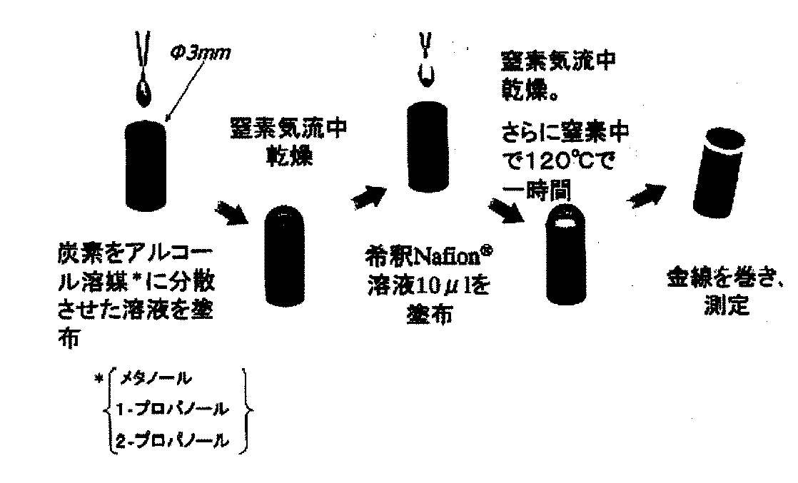
作用電極としては、φ3mm×15mmのガラス状カーボンロッド(東海カーボン社製電気・化学用黒鉛「グラッシーカーボン」からなるロッド:GCロッド)の表面に、本発明で用いる気相法炭素繊維の分散液を均一に塗布・乾燥後、100倍希釈したナフィオン(登録商標)溶液10μlを均一に塗布・乾燥して得られるものを用いる。気相法炭素繊維の分散媒としては、メタノール、1−プロパノール及び2−プロパノールの少なくとも1種を用いる。気相法炭素繊維の被覆量は、36〜42μg(固形分)である。かかる範囲内であれば、被覆量の違いに影響されず気相法炭素繊維の物性(電位差、電流ピーク)測定が可能である。ナフィオン希釈溶剤としては純水を用いる。分散液を塗布・乾燥する場合の乾燥雰囲気は窒素気流中における自然乾燥とする。また、ナフィオン溶液を塗布・乾燥する場合の乾燥雰囲気は窒素気流中における加熱乾燥(120℃で1時間)とする。ナフィオン溶液は、気相法炭素繊維の接着性を高めるために使用しており、電極活物質を構成するものではない。対極としては白金黒電極を用いる。参照電極としては可逆水素電極を用いる。 As a working electrode, a dispersion of vapor grown carbon fiber used in the present invention on the surface of a glassy carbon rod of φ3 mm × 15 mm (rod: GC rod made of graphite and glass for electric / chemical use manufactured by Tokai Carbon Co.) After uniformly coating and drying, a solution obtained by uniformly coating and drying 10 μl of Nafion (registered trademark) solution diluted 100 times is used. As a dispersion medium for vapor grown carbon fiber, at least one of methanol, 1-propanol and 2-propanol is used. The coating amount of the vapor grown carbon fiber is 36 to 42 μg (solid content). Within this range, the physical properties (potential difference, current peak) of vapor grown carbon fiber can be measured without being affected by the difference in the coating amount. Pure water is used as the Nafion dilution solvent. The drying atmosphere when applying and drying the dispersion is natural drying in a nitrogen stream. The drying atmosphere when applying and drying the Nafion solution is heat drying in a nitrogen stream (120 ° C. for 1 hour). The Nafion solution is used to enhance the adhesion of vapor grown carbon fiber and does not constitute an electrode active material. A platinum black electrode is used as the counter electrode. A reversible hydrogen electrode is used as the reference electrode.
電解液としては、1molのバナジウム(IV)を4molの硫酸に溶解したものを使用する。また、セル内の雰囲気は25℃の循環窒素雰囲気とする。 As an electrolytic solution, 1 mol of vanadium (IV) dissolved in 4 mol of sulfuric acid is used. The atmosphere in the cell is a circulating nitrogen atmosphere at 25 ° C.
作用電極の酸化・還元電位差(5価の酸化ピークと4価の還元ピークとの電位差)測定時は、三電極式セルにポテンションスタット及びファンクションジェネレーターをつなぎ、作用電極電位を時間と共に直線的に変化させて、酸化・還元電位及び酸化・還元電流を記録計で記録する。詳細には、ファンクションジェネレーターから三角波を供給し、作用電極電位を経時的に負から正へ、正から負へ繰り返し変化させて、酸化・還元電圧を水平軸方向に記録し、酸化・還元電流を垂直軸方向に記録する。三角波における正側の作用電極電位の限界は1600〜1800mV程度、負側の作用電極電位の限界は300〜400mV程度とする。また、作用電極電位の走査速度は50〜500mV/sの範囲内とし、酸化電流及び還元電流のピーク絶対値を評価する場合は、特に300〜500mV/sの範囲内とする。 When measuring the oxidation / reduction potential difference of the working electrode (potential difference between the pentavalent oxidation peak and the tetravalent reduction peak), a potentiostat and a function generator are connected to the three-electrode cell, and the working electrode potential is linearly changed with time. The oxidation / reduction potential and the oxidation / reduction current are recorded with a recorder. Specifically, a triangular wave is supplied from a function generator, the working electrode potential is repeatedly changed from negative to positive and positive to negative over time, and the oxidation / reduction voltage is recorded in the horizontal axis direction. Record in the vertical direction. The limit of the positive working electrode potential in the triangular wave is about 1600 to 1800 mV, and the limit of the negative working electrode potential is about 300 to 400 mV. In addition, the scanning speed of the working electrode potential is in the range of 50 to 500 mV / s, and particularly in the range of 300 to 500 mV / s when the peak absolute values of the oxidation current and the reduction current are evaluated.
以上より、サイクリックボルタンメトリーの条件を詳細に明記して本発明の炭素電極材料を説明すると、次のようになる。 From the above, the carbon electrode material of the present invention will be described as follows by specifying the conditions of cyclic voltammetry in detail.
即ち、「気相法炭素繊維を含む電極材料であって、
(1)前記炭素繊維は、平均繊維径が0.05〜0.3μmであり、平均アスペクト比が10〜500であり、
(2)前記炭素繊維は、当該炭素繊維36〜42μg(固形分)をφ3mm×15mmのガラス状カーボンロッド表面に均一に被覆してなるものを作用電極とし、対極を白金黒電極とし、参照電極を可逆水素電極とする三電極式セルを用いるサイクリックボルタンメトリーにおいて、電解液として1molのバナジウム(IV)を4molの硫酸に溶解したものを使用し、セル内の雰囲気を25℃の循環窒素雰囲気とし、走査速度を50〜500mV/sとした場合の5価の酸化ピークと4価の還元ピークとの電位差が0.1〜0.3Vの範囲内である、
ことを特徴とするバナジウム系レドックスフロー電池用炭素電極材料。」
サイクリックボルタンメトリーにより本発明で用いる気相法炭素繊維の酸化・還元電圧を水平軸方向に記録し、酸化・還元電流を垂直軸方向に記録して得られるグラフ(サイクリックボルタモグラム)の一例を図5に示す。
That is, “It is an electrode material containing vapor grown carbon fiber,
(1) The carbon fiber has an average fiber diameter of 0.05 to 0.3 μm, an average aspect ratio of 10 to 500,
(2) The carbon fiber is obtained by uniformly coating the surface of a glassy carbon rod having a diameter of 3 mm × 15 mm with 36 to 42 μg (solid content) of the carbon fiber as a working electrode, a counter electrode as a platinum black electrode, and a reference electrode. In cyclic voltammetry using a three-electrode cell with a reversible hydrogen electrode, 1 mol of vanadium (IV) dissolved in 4 mol of sulfuric acid is used as the electrolyte, and the atmosphere in the cell is a 25 ° C. circulating nitrogen atmosphere. The potential difference between the pentavalent oxidation peak and the tetravalent reduction peak when the scanning speed is 50 to 500 mV / s is in the range of 0.1 to 0.3 V.
A carbon electrode material for vanadium-based redox flow batteries. "
An example of a graph (cyclic voltammogram) obtained by recording the oxidation / reduction voltage of the vapor grown carbon fiber used in the present invention in the horizontal axis direction and recording the oxidation / reduction current in the vertical axis direction by cyclic voltammetry As shown in FIG.
図5のグラフの形状からは、作用電極電位が正方向(アノード方向)に移動する際、特定の電位より正の領域において溶液中の化合物から電子が電極に移り、酸化反応が進行することが分かる。酸化反応の進行に対応して、電極から溶液を経てさらに対極へ向かう方向には酸化電流が流れる。そして作用電極電位が正方向へ移行するに従って、酸化電流は最大値を経由し、その後減少し、ほぼ一定値に落ち着く。 From the shape of the graph of FIG. 5, when the working electrode potential moves in the positive direction (anode direction), electrons move from the compound in the solution to the electrode in a region positive from the specific potential, and the oxidation reaction proceeds. I understand. Corresponding to the progress of the oxidation reaction, an oxidation current flows in a direction from the electrode to the counter electrode through the solution. As the working electrode potential moves in the positive direction, the oxidation current passes through the maximum value and then decreases and settles to a substantially constant value.
サイクリックボルタンメトリーでは、作用電極電位の正方向への走査により酸化電流が流れることに対応して電極付近には酸化体が蓄積される。また、正方向の電位走査に続く負方向(カソード方向)への電位走査により今度は酸化体が還元される向きに還元電流が流れる。そのため、作用電極電位を正方向・負方向へ繰り返し走査することにより、図5のようなアノード・カソード両方向に最大値をもった電圧・電流の関係が得られる。電極反応に関与する化合物の酸化還元電位は、二つの電流ピークの中間電位(酸化電流のピーク時の電位と還元電流のピーク時の電位との中間)として求められる。 In cyclic voltammetry, an oxidant is accumulated in the vicinity of the electrode in response to the oxidation current flowing by scanning the working electrode potential in the positive direction. In addition, a reduction current flows in the direction in which the oxidant is reduced by the potential scan in the negative direction (cathode direction) following the potential scan in the positive direction. Therefore, by repeatedly scanning the working electrode potential in the positive and negative directions, a voltage / current relationship having maximum values in both the anode and cathode directions as shown in FIG. 5 can be obtained. The oxidation-reduction potential of the compound involved in the electrode reaction is determined as an intermediate potential between two current peaks (intermediate between the potential at the peak of the oxidation current and the potential at the peak of the reduction current).
なお、溶液中の化学種の反応が十分に速ければ、電極表面では電気化学的な平衡が常に成り立つ。つまり、作用電極電位を経時的に変化させると、電極表面での酸化還元体の濃度はネルンストの下記式を満たすように変化する。 If the reaction of chemical species in the solution is sufficiently fast, electrochemical equilibrium is always established on the electrode surface. That is, when the working electrode potential is changed over time, the concentration of the redox substance on the electrode surface changes so as to satisfy the following Nernst equation.
E=E○+(RT/nF)log[ox]/[red]
〔ただし、E、E○は、それぞれ、電極電位、標準酸化還元電位であり、R、T、n、Fは気体定数、絶対温度、移動電子数、ファラデー定数である。[ox][red]は、それぞれ電極近傍の酸化体、還元体の濃度である。〕
次いで、気相法炭素繊維の製造方法について説明する。気相法では、鉄、ニッケル等の超微粒子金属(触媒)の触媒作用によって先ず炭素六角網面がチューブ状に成長した第1段階生成繊維(素繊維)がいわゆる長さ成長過程を経て形成される。その後、素繊維の周辺に熱分解炭素層が沈積して太さ成長が行われる。従って、気相法炭素繊維は、超微粒子金属触媒によって形成される熱分解炭素繊維と称される場合もある。
E = E o + (RT / nF) log [ox] / [red]
[However, E, E ○, respectively, electrode potential, a standard oxidation-reduction potential, R, T, n, F is the gas constant, absolute temperature, mobile electron count is the Faraday constant. [Ox] [red] are the concentrations of oxidant and reductant near the electrode, respectively. ]
Next, a method for producing vapor grown carbon fiber will be described. In the vapor phase method, first-stage formed fibers (elementary fibers) in which the carbon hexagonal network surface is first grown into a tube shape by the catalytic action of ultrafine metal (catalyst) such as iron and nickel are formed through a so-called length growth process. The Thereafter, a pyrolytic carbon layer is deposited around the raw fibers to grow in thickness. Therefore, vapor grown carbon fiber is sometimes referred to as pyrolytic carbon fiber formed by an ultrafine metal catalyst.
気相法による炭素繊維の製造方法としては、例えば、ベンゼン等の有機化合物とフェロセン等の超微粒子金属触媒とをキャリアガスと共に高温の反応炉に導入し、反応炉内に設置した基板又は反応炉壁に目的の炭素繊維を生成させる製造方法が知られている。 As a carbon fiber production method by a vapor phase method, for example, an organic compound such as benzene and an ultrafine metal catalyst such as ferrocene are introduced together with a carrier gas into a high-temperature reactor, and a substrate or reactor installed in the reactor A production method for producing a target carbon fiber on a wall is known.
反応炉としては、一般にキャリアガスの入口と出口とを備えた円筒炉を使用する。特に頂部に原料ガス供給ノズルを備えた縦型加熱円筒炉が好ましい。炉材としてはアルミナ質ムライトが好ましい。 As the reaction furnace, a cylindrical furnace having a carrier gas inlet and outlet is generally used. In particular, a vertical heating cylindrical furnace having a source gas supply nozzle at the top is preferable. The furnace material is preferably alumina mullite.
原料ガスとしては、炭素原料(有機化合物)と超微粒子金属触媒との混合物を用いる。 As the source gas, a mixture of a carbon source (organic compound) and an ultrafine metal catalyst is used.
炭素原料としては、例えば、ベンゼン、トルエン、キシレン、メタノール、エタノール、ナフタレン、フェナントレン、シクロプロパン、シクロペンテン、シクロヘキサン、チオフェン等の有機化合物、それらの混合物、揮発油、灯油などが挙げられる。この中でも、ベンゼン、トルエン、キシレン等の芳香族化合物が好ましい。 Examples of the carbon raw material include organic compounds such as benzene, toluene, xylene, methanol, ethanol, naphthalene, phenanthrene, cyclopropane, cyclopentene, cyclohexane, and thiophene, mixtures thereof, volatile oil, and kerosene. Among these, aromatic compounds such as benzene, toluene and xylene are preferable.
超微粒子金属触媒としては、遷移金属又はその化合物が使用できる。例えば、周期律表第IVa ,Va ,VIa ,VIIa,VIII族の元素;それらの合金;混合物;それらを含む無機又は有機化合物が挙げられる。具体的には、Fe,Ni,Co等の超微粉(30nm以下)、フェロセン、ニッケルセンなどの有機化合物が好ましい。フェロセン等の有機化合物は熱分解によりFe等の超微粒子が得られるため好ましい。 As the ultrafine metal catalyst, a transition metal or a compound thereof can be used. For example, elements of group IVa, Va, VIa, VIIa, VIII of the periodic table; alloys thereof; mixtures; inorganic or organic compounds containing them. Specifically, an ultrafine powder (30 nm or less) such as Fe, Ni, and Co, and an organic compound such as ferrocene and nickelcene are preferable. Organic compounds such as ferrocene are preferred because ultrafine particles such as Fe can be obtained by thermal decomposition.
原料ガス中の触媒量(金属分)としては、有機化合物の炭素量(フェロセン等の使用の場合はその炭素を含めた合計量)に対して、0.03〜10重量%程度が好ましく、0.1〜5重量%程度がより好ましい。 The catalyst amount (metal content) in the raw material gas is preferably about 0.03 to 10% by weight with respect to the carbon amount of the organic compound (in the case of using ferrocene, the total amount including the carbon). About 1 to 5% by weight is more preferable.
原料ガスを円筒炉に導入する際は、円筒炉内を水素ガス雰囲気に置換後、円筒炉内の温度を1000〜1300℃に加熱しておくことが好ましい。 When introducing the raw material gas into the cylindrical furnace, it is preferable to heat the temperature in the cylindrical furnace to 1000 to 1300 ° C. after replacing the inside of the cylindrical furnace with a hydrogen gas atmosphere.
前記雰囲気の円筒炉内に原料ガスを導入することにより、原料ガスが熱分解反応して気相法炭素繊維が円筒炉壁に生成する。気相法炭素繊維は、直径が小さく比較的大きなアスペクト比を有するため、繊維どうしが絡まりあった毛玉様の凝集体の状態で得られ易い。他の反応条件は、炭素繊維が所定の要件を具備する範囲内で適宜調整できる。 By introducing the raw material gas into the cylindrical furnace in the atmosphere, the raw material gas undergoes a thermal decomposition reaction to generate vapor grown carbon fiber on the cylindrical furnace wall. Vapor grown carbon fibers have a small diameter and a relatively large aspect ratio, and are thus easily obtained in the form of pill-like aggregates in which fibers are entangled. Other reaction conditions can be appropriately adjusted within a range in which the carbon fiber has predetermined requirements.
この生成物をそのまま本発明で用いる気相法炭素繊維としてもよいが、これを不活性雰囲気中、2000℃以上で熱処理したものを用いる方が好ましい。かかる2000℃以上の熱処理をさらに施したものも、本発明における気相法炭素繊維に含まれる。気相法炭素繊維は易黒鉛化性であり、2000℃以上で熱処理した場合には、結晶性がより発達して電気伝導性が向上する。また、2000℃以上の熱処理により、繊維断面が多角化し、内部に空隙が生じ易くなるため、短径方向の断面において中心部に空隙を有し、該空隙の周囲に炭素六角網面の結晶が年輪状に積層した構造が得られ易い。 This product may be used as a vapor grown carbon fiber used in the present invention as it is, but it is preferable to use a product obtained by heat-treating this product at 2000 ° C. or higher in an inert atmosphere. Those subjected to such heat treatment at 2000 ° C. or higher are also included in the vapor grown carbon fiber in the present invention. Vapor grown carbon fiber is graphitizable, and when heat treated at 2000 ° C. or higher, crystallinity is further developed and electrical conductivity is improved. In addition, since the fiber cross section is diversified by heat treatment at 2000 ° C. or more, and voids are easily generated inside, there is a void at the center in the cross section in the minor axis direction, and the crystal of the carbon hexagonal network is formed around the void. A structure in which annual rings are stacked is easy to obtain.
本発明の炭素電極材料は、公知の手段によりレドックスフロー電池用炭素電極とできる。炭素電極の形状は特に限定されないが、シート状(フェルトシート状)が一般的である。炭素電極材料をシート状に成形する方法は特に限定されず、例えば、フィルムプレス成形、適当な分散媒に分散後、キャスティングする抄紙法等が挙げられる。炭素電極には、適宜、触媒金属、バインダー等の添加物を配合できる。 The carbon electrode material of the present invention can be used as a redox flow battery carbon electrode by known means. Although the shape of a carbon electrode is not specifically limited, A sheet form (felt sheet form) is common. The method of forming the carbon electrode material into a sheet is not particularly limited, and examples thereof include film press molding, and a papermaking method in which the carbon electrode material is cast after being dispersed in an appropriate dispersion medium. The carbon electrode can be appropriately mixed with additives such as a catalyst metal and a binder.
また、このようにして製造される炭素電極は、公知の手段によりバナジウム系レドックスフロー電池に組み込むことができる。電池の運転方法は、公知のバナジウム系レドックスフロー電池の運転方法に従えばよい。 Moreover, the carbon electrode manufactured in this way can be incorporated in a vanadium redox flow battery by a known means. The operation method of a battery should just follow the operation method of a well-known vanadium-type redox flow battery.
本発明の炭素電極材料は、酸化・還元の可逆反応性が高い。そのため、レドックスフロー電池の内部抵抗を低くすることができ、電池の出力を高めることができる。 The carbon electrode material of the present invention has high reversible reactivity of oxidation / reduction. Therefore, the internal resistance of the redox flow battery can be lowered, and the output of the battery can be increased.
以下に実施例及び比較例を示し、本発明をより具体的に説明する。但し、本発明は実施例に限定されない。 Hereinafter, the present invention will be described in more detail with reference to examples and comparative examples. However, the present invention is not limited to the examples.
実施例1〜3(気相法炭素繊維「VGCF」の製造)
反応管として、頂部に原料ガス供給ノズルを取り付けた縦型加熱円筒炉を用意した。
Examples 1 to 3 (Production of vapor grown carbon fiber “VGCF”)
A vertical heating cylindrical furnace having a source gas supply nozzle attached to the top was prepared as a reaction tube.
反応管内に窒素ガスを流通させて酸素ガスを排気した後、水素ガスを流通させて水素ガス雰囲気に置換した。その後、反応管の昇温を開始して1200℃まで温度を上げた。 After nitrogen gas was circulated in the reaction tube and oxygen gas was exhausted, hydrogen gas was circulated and replaced with a hydrogen gas atmosphere. Thereafter, the temperature of the reaction tube was increased and the temperature was increased to 1200 ° C.
次いで、原料液を原料ガス供給ノズルから気化させながら、キャリアガスである水素ガスとともに反応管内に導入した。原料液としては、フェロセン0.6kgとチオフェン0.15kgをベンゼン14kgに溶解したものを用いた。 Next, the raw material liquid was introduced into the reaction tube together with hydrogen gas as the carrier gas while vaporizing from the raw material gas supply nozzle. As the raw material liquid, a solution obtained by dissolving 0.6 kg of ferrocene and 0.15 kg of thiophene in 14 kg of benzene was used.
反応を1時間行った後、生成物をアルゴン雰囲気中、2800℃で30分間加熱して本発明の気相法炭素繊維を得た。 After performing the reaction for 1 hour, the product was heated at 2800 ° C. for 30 minutes in an argon atmosphere to obtain vapor grown carbon fiber of the present invention.
気相法炭素繊維(VGCF)の物性は次の通りである。 The physical properties of vapor grown carbon fiber (VGCF) are as follows.
*1 表1中、比表面積は、比表面積測定装置「NOVA−1200」ユアサアイオニクス株式会社製を用いてBET法により測定した(以下同じ)。
*2 表1中、比抵抗は、気相法炭素繊維を嵩密度0.8g/cm2に圧縮したものの比抵抗を測定した値である(以下同じ)。
* 1 In Table 1, the specific surface area was measured by the BET method using a specific surface area measuring device “NOVA-1200” manufactured by Yuasa Ionics Co., Ltd. (hereinafter the same).
* 2 In Table 1, the specific resistance is a value obtained by measuring the specific resistance of a vapor grown carbon fiber compressed to a bulk density of 0.8 g / cm 2 (hereinafter the same).
上記気相法炭素繊維を、ジェットミルを用いて解砕したもの(以下「VGCF−H」と記載する)の物性は次の通りである。「VGCF−H」を実施例1の炭素電極材料とする。 The physical properties of the vapor-grown carbon fiber crushed using a jet mill (hereinafter referred to as “VGCF-H”) are as follows. “VGCF-H” is used as the carbon electrode material of Example 1.
上記VGCF−Hを羽根型高速ミキサー(20000rpm)を用いて1分間解砕したもの(以下「VGCF−cut」と記載する)の物性は次の通りである。「VGCF−cut」を実施例2の炭素電極材料とする。 The physical properties of the above VGCF-H pulverized for 1 minute using a blade type high speed mixer (20000 rpm) (hereinafter referred to as “VGCF-cut”) are as follows. “VGCF-cut” is the carbon electrode material of Example 2.
さらに、上記VGCF−cutを60%硝酸に70℃で5時間浸漬して表面を親水化したもの(以下「VGCF−cut親水処理」と記載する)を作製した。「VGCF−cut親水処理」を実施例3の炭素電極材料とする。 Further, the above VGCF-cut was immersed in 60% nitric acid at 70 ° C. for 5 hours to make the surface hydrophilic (hereinafter referred to as “VGCF-cut hydrophilic treatment”). “VGCF-cut hydrophilic treatment” is used as the carbon electrode material of Example 3.
比較例1〜3(炭素電極材料の作製)
比較例1〜3の炭素電極材料として、順にガラス状炭素、カーボンブラック及びカーボンナノホーンを用意した。
Comparative Examples 1 to 3 (Production of carbon electrode material)
As carbon electrode materials of Comparative Examples 1 to 3, glassy carbon, carbon black, and carbon nanohorn were prepared in order.
ガラス状炭素は、黒色ガラス状のガス不透過性炭素である。ここでは商品名「電気・化学用黒鉛:グラッシーカーボン」(東海カーボン社製)を用いた。これは前記したGCと同じである。 Glassy carbon is black glassy gas impermeable carbon. Here, the trade name “graphite for electricity / chemical: glassy carbon” (manufactured by Tokai Carbon Co., Ltd.) was used. This is the same as the GC described above.
カーボンブラックは、一般に炭化水素又は油脂の不完全燃焼により得られる微細な黒色炭素粉末である。ここでは商品名「Vulcan」(Cabot社製)を用いた。以下、商品名を用いて説明する。 Carbon black is a fine black carbon powder generally obtained by incomplete combustion of hydrocarbons or fats. Here, the trade name “Vulcan” (manufactured by Cabot) was used. Hereinafter, description will be made using product names.
カーボンナノホーンは、先端を尖らせたカーボンナノチューブの一種である。ここでは商品名「カーボンナノホーン」(宝泉社製)を用いた。以下「CNH」と記載する。 Carbon nanohorns are a type of carbon nanotube with a sharpened tip. Here, the trade name “Carbon Nano Horn” (manufactured by Hosen Co., Ltd.) was used. Hereinafter referred to as “CNH”.
試験例1(酸化・還元電位差測定)
図3に示される三電極式セルを用いてサイクリックボルタンメトリーを行って実施例1〜3及び比較例1〜3の炭素電極材料の特性(酸化・還元電位差及び酸化・還元電流の関係)を評価した。
Test Example 1 (Oxidation / reduction potential difference measurement)
Cyclic voltammetry is performed using the three-electrode cell shown in FIG. 3 to evaluate the characteristics (relationship between oxidation / reduction potential difference and oxidation / reduction current) of Examples 1 to 3 and Comparative Examples 1 to 3. did.
作用電極の作製方法は次の通りである。即ち、φ3mm×15mmのGCロッドの表面に、メタノールに分散させた炭素電極材料(固形分換算39μg)を均一に塗布・乾燥後、ナフィオン(登録商標)水溶液(100倍希釈)10μlをさらに均一に塗布・乾燥して得られるものを用いた。なお、炭素電極材料がGCの場合には、GCロッドの表面に上記ナフィオン水溶液のみを塗布してなる作用電極を用いた。乾燥雰囲気は窒素雰囲気とした。対極としては白金黒電極を用いた。参照電極としては可逆水素電極を用いた。 The production method of the working electrode is as follows. That is, a carbon electrode material (39 μg in terms of solid content) dispersed in methanol is uniformly applied to the surface of a φ3 mm × 15 mm GC rod and dried, and then 10 μl of Nafion (registered trademark) aqueous solution (100-fold dilution) is further uniformly obtained. What was obtained by coating and drying was used. When the carbon electrode material was GC, a working electrode obtained by applying only the Nafion aqueous solution to the surface of the GC rod was used. The drying atmosphere was a nitrogen atmosphere. A platinum black electrode was used as the counter electrode. A reversible hydrogen electrode was used as a reference electrode.
電解液としては、1molのバナジウム(IV)を4molの硫酸に溶解したものを用いた。作用電極の酸化・還元電位差(5価の酸化ピークと4価の還元ピークとの電位差)測定時は、セル内の雰囲気を25℃の循環窒素雰囲気とした。測定時は三電極式セルにポテンションスタット及びファンクションジェネレーターをつなぎ、作用電極電位を時間と共に直線的に変化させて、酸化・還元電位及び酸化・還元電流を記録計で記録した。詳細には、ファンクションジェネレーターから三角波を供給し、作用電極電位を経時的に負から正へ、正から負へ繰り返し変化させて酸化・還元電圧を水平軸方向に記録し、酸化・還元電流を垂直軸方向に記録した。なお、三角波形における正側の作用電極電位の限界は1700mV、負側の作用電極電位の限界は350mVとした。作用電極電位の走査速度は300mV/sとした。 As the electrolytic solution, 1 mol of vanadium (IV) dissolved in 4 mol of sulfuric acid was used. When measuring the oxidation / reduction potential difference of the working electrode (potential difference between the pentavalent oxidation peak and the tetravalent reduction peak), the atmosphere in the cell was a circulating nitrogen atmosphere at 25 ° C. At the time of measurement, a potentiostat and a function generator were connected to a three-electrode cell, the working electrode potential was changed linearly with time, and the oxidation / reduction potential and oxidation / reduction current were recorded with a recorder. Specifically, a triangular wave is supplied from a function generator, the working electrode potential is repeatedly changed from negative to positive and positive to negative over time, and the oxidation / reduction voltage is recorded in the horizontal axis direction, and the oxidation / reduction current is vertical. Recorded axially. The limit of the positive working electrode potential in the triangular waveform was 1700 mV, and the limit of the negative working electrode potential was 350 mV. The scanning speed of the working electrode potential was 300 mV / s.
各々のサイクリックボルタモグラムを図5及び図6に示す。 Each cyclic voltammogram is shown in FIGS.
サイクリックボルタモグラムから算出された酸化・還元電位差は次の通りである。 The oxidation-reduction potential difference calculated from the cyclic voltammogram is as follows.
本発明の炭素電極材料(気相法炭素繊維)は、酸化・還元電位差が0.1〜0.3Vの範囲内であり酸化・還元の可逆反応性が高いことがわかる。また、図5及び図6の結果から明らかなように、酸化電流及び還元電流のピークの絶対値が共に150mA/cm2以上であり電池の反応性を高められることが分かる。 It can be seen that the carbon electrode material (vapor phase grown carbon fiber) of the present invention has an oxidation / reduction potential difference in the range of 0.1 to 0.3 V and high reversible reactivity of oxidation / reduction. Further, as is apparent from the results of FIGS. 5 and 6, it can be seen that the absolute values of the peaks of the oxidation current and the reduction current are both 150 mA / cm 2 or more, and the reactivity of the battery can be enhanced.
一方、比較例の炭素電極材料は、GCにおいては酸化・還元電位差が非常に大きく、酸化・還元の可逆反応性が低いことが分かる。また、図5及び図6の結果から明らかなように、GC、Vulcan及びCNHは酸化電流及び還元電流のピーク絶対値が150mA/cm2未満であり、本発明の炭素電極材料に比して電池の反応性を高められないことが分かる。 On the other hand, it can be seen that the carbon electrode material of the comparative example has a very large oxidation / reduction potential difference in GC and low reversibility of oxidation / reduction. Further, as is apparent from the results of FIGS. 5 and 6, GC, Vulcan, and CNH have a peak absolute value of an oxidation current and a reduction current of less than 150 mA / cm 2, which is a battery as compared with the carbon electrode material of the present invention. It turns out that the reactivity of cannot be improved.
Claims (6)
A vanadium redox flow battery comprising the carbon electrode according to claim 5.
Priority Applications (1)
| Application Number | Priority Date | Filing Date | Title |
|---|---|---|---|
| JP2004342527A JP2006156029A (en) | 2004-11-26 | 2004-11-26 | Carbon electrode material for vanadium redox flow battery |
Applications Claiming Priority (1)
| Application Number | Priority Date | Filing Date | Title |
|---|---|---|---|
| JP2004342527A JP2006156029A (en) | 2004-11-26 | 2004-11-26 | Carbon electrode material for vanadium redox flow battery |
Publications (1)
| Publication Number | Publication Date |
|---|---|
| JP2006156029A true JP2006156029A (en) | 2006-06-15 |
Family
ID=36634068
Family Applications (1)
| Application Number | Title | Priority Date | Filing Date |
|---|---|---|---|
| JP2004342527A Withdrawn JP2006156029A (en) | 2004-11-26 | 2004-11-26 | Carbon electrode material for vanadium redox flow battery |
Country Status (1)
| Country | Link |
|---|---|
| JP (1) | JP2006156029A (en) |
Cited By (39)
| Publication number | Priority date | Publication date | Assignee | Title |
|---|---|---|---|---|
| WO2008105337A1 (en) * | 2007-02-28 | 2008-09-04 | Tomoegawa Co., Ltd. | Gas diffusion electrode for solid polymer fuel cell, membrane-electrode assembly for solid polymer fuel cell and method for producing the same, and solid polymer fuel cell |
| JP2013137958A (en) * | 2011-12-28 | 2013-07-11 | Asahi Kasei E-Materials Corp | Redox flow secondary battery |
| CN103219530A (en) * | 2013-04-03 | 2013-07-24 | 胡国良 | Treatment method of vanadium battery carbon felt electrode |
| KR20140021661A (en) * | 2011-04-11 | 2014-02-20 | 유나이티드 테크놀로지스 코포레이션 | Flow battery having electrodes with a plurality of different pore sizes and/or different layers |
| US8785023B2 (en) | 2008-07-07 | 2014-07-22 | Enervault Corparation | Cascade redox flow battery systems |
| JP2014137994A (en) * | 2013-01-18 | 2014-07-28 | Samsung Sdi Co Ltd | Catalyst for fuel cell, electrode for fuel cell using the same, membrane-electrode assembly for fuel cell and fuel cell system |
| JP2014154459A (en) * | 2013-02-13 | 2014-08-25 | Nippon Zeon Co Ltd | Conductive film, gas diffusion layer for fuel cell, catalyst layer for fuel cell, electrode for fuel cell, membrane electrode assembly for fuel cell, fuel cell, and method for manufacturing membrane electrode assembly for fuel cell |
| WO2014168081A1 (en) | 2013-04-11 | 2014-10-16 | 昭和電工株式会社 | Carbon member, carbon member manufacturing method, redox flow battery and fuel cell |
| US8906529B2 (en) | 2008-07-07 | 2014-12-09 | Enervault Corporation | Redox flow battery system for distributed energy storage |
| US8916281B2 (en) | 2011-03-29 | 2014-12-23 | Enervault Corporation | Rebalancing electrolytes in redox flow battery systems |
| US8980484B2 (en) | 2011-03-29 | 2015-03-17 | Enervault Corporation | Monitoring electrolyte concentrations in redox flow battery systems |
| WO2015072452A1 (en) | 2013-11-13 | 2015-05-21 | 昭和電工株式会社 | Electrode material, redox flow battery electrode, redox flow battery, and method for producing electrode material |
| JP2015122231A (en) * | 2013-12-24 | 2015-07-02 | 住友電気工業株式会社 | Redox flow cell |
| JP5890561B1 (en) * | 2015-05-01 | 2016-03-22 | 株式会社ギャラキシー | Electrolyzer and battery |
| CN105742669A (en) * | 2014-12-09 | 2016-07-06 | 中国科学院大连化学物理研究所 | Electrolyte flow homogenization method of redox flow battery |
| CN105814721A (en) * | 2013-12-27 | 2016-07-27 | 日本瑞翁株式会社 | Conductive film, gas diffusion layer for fuel cells, catalyst layer for fuel cells, electrode for fuel cells, membrane electrode assembly for fuel cells, and fuel cell |
| WO2016158216A1 (en) * | 2015-03-31 | 2016-10-06 | 株式会社東北テクノアーチ | Vanadium redox cell |
| WO2016159348A1 (en) * | 2015-04-01 | 2016-10-06 | 昭和電工株式会社 | Electrode material, electrode of redox flow battery, and redox flow battery |
| JP2016213177A (en) * | 2016-01-05 | 2016-12-15 | 株式会社ギャラキシー | Electrolytic cell and battery |
| JP2017027920A (en) * | 2015-07-28 | 2017-02-02 | 東洋紡株式会社 | Electrode material for redox battery |
| JPWO2015182138A1 (en) * | 2014-05-30 | 2017-04-20 | 日本ゼオン株式会社 | Redox catalyst, electrode material, electrode, membrane electrode assembly for fuel cell, and fuel cell |
| US9853310B2 (en) | 2013-12-23 | 2017-12-26 | United Technologies Corporation | Distribution of electrolytes in a flow battery |
| US9966618B2 (en) | 2012-12-09 | 2018-05-08 | United Technologies Corporation | Flow battery with voltage-limiting device |
| US10044058B2 (en) | 2013-03-15 | 2018-08-07 | United Technologies Corporation | Reactivation of flow battery electrode by exposure to oxidizing solution |
| US10050290B2 (en) | 2013-12-26 | 2018-08-14 | United Technologies Corporation | Rebalancing electrolyte concentration in flow battery using pressure differential |
| US10115983B2 (en) | 2013-06-13 | 2018-10-30 | United Technologies Corporation | Flow battery with manifold passage that varies in cross-section |
| US10135085B2 (en) | 2013-05-16 | 2018-11-20 | United Technologies Corporation | Flow battery with hydrated ion-exchange membrane having maximum water domain cluster sizes |
| US10158140B2 (en) | 2011-12-20 | 2018-12-18 | United Technologies Corporation | Flow battery with enhanced durability |
| US10164283B2 (en) | 2014-01-07 | 2018-12-25 | United Technologies Corporation | Flow battery with rotationally symmetric manifold plates |
| US10637082B2 (en) | 2011-12-20 | 2020-04-28 | United Technologies Corporation | Flow battery with carbon paper |
| US10680259B2 (en) | 2014-09-15 | 2020-06-09 | Raytheon Technologies Corporation | Regeneration of flow battery electrode |
| US10707514B2 (en) | 2016-08-05 | 2020-07-07 | Showa Denko K.K. | Redox flow battery |
| US10727498B2 (en) | 2014-12-26 | 2020-07-28 | Showa Denko K.K. | Redox flow battery electrode, and redox flow battery |
| US10892499B2 (en) | 2013-03-15 | 2021-01-12 | Raytheon Technologies Corporation | Flow battery flow field having volume that is function of power parameter, time parameter and concentration parameter |
| US10903505B2 (en) | 2016-02-26 | 2021-01-26 | Nisshinbo Holdings Inc. | Carbon catalyst for redox flow battery electrodes |
| US10903504B2 (en) | 2016-02-26 | 2021-01-26 | Nisshinbo Holdings Inc. | Carbon catalyst for redox flow battery electrodes |
| US11056698B2 (en) | 2018-08-02 | 2021-07-06 | Raytheon Technologies Corporation | Redox flow battery with electrolyte balancing and compatibility enabling features |
| US11271226B1 (en) | 2020-12-11 | 2022-03-08 | Raytheon Technologies Corporation | Redox flow battery with improved efficiency |
| CN114503313A (en) * | 2019-10-09 | 2022-05-13 | 住友电气工业株式会社 | Electrode, battery cell, battery stack and redox flow battery system |
-
2004
- 2004-11-26 JP JP2004342527A patent/JP2006156029A/en not_active Withdrawn
Cited By (50)
| Publication number | Priority date | Publication date | Assignee | Title |
|---|---|---|---|---|
| WO2008105337A1 (en) * | 2007-02-28 | 2008-09-04 | Tomoegawa Co., Ltd. | Gas diffusion electrode for solid polymer fuel cell, membrane-electrode assembly for solid polymer fuel cell and method for producing the same, and solid polymer fuel cell |
| US8906529B2 (en) | 2008-07-07 | 2014-12-09 | Enervault Corporation | Redox flow battery system for distributed energy storage |
| US8785023B2 (en) | 2008-07-07 | 2014-07-22 | Enervault Corparation | Cascade redox flow battery systems |
| US8980484B2 (en) | 2011-03-29 | 2015-03-17 | Enervault Corporation | Monitoring electrolyte concentrations in redox flow battery systems |
| US8916281B2 (en) | 2011-03-29 | 2014-12-23 | Enervault Corporation | Rebalancing electrolytes in redox flow battery systems |
| KR101940148B1 (en) * | 2011-04-11 | 2019-01-18 | 유나이티드 테크놀로지스 코포레이션 | Flow battery having electrodes with a plurality of different pore sizes and/or different layers |
| KR20140021661A (en) * | 2011-04-11 | 2014-02-20 | 유나이티드 테크놀로지스 코포레이션 | Flow battery having electrodes with a plurality of different pore sizes and/or different layers |
| US10637082B2 (en) | 2011-12-20 | 2020-04-28 | United Technologies Corporation | Flow battery with carbon paper |
| US10158140B2 (en) | 2011-12-20 | 2018-12-18 | United Technologies Corporation | Flow battery with enhanced durability |
| JP2013137958A (en) * | 2011-12-28 | 2013-07-11 | Asahi Kasei E-Materials Corp | Redox flow secondary battery |
| US9966618B2 (en) | 2012-12-09 | 2018-05-08 | United Technologies Corporation | Flow battery with voltage-limiting device |
| JP2014137994A (en) * | 2013-01-18 | 2014-07-28 | Samsung Sdi Co Ltd | Catalyst for fuel cell, electrode for fuel cell using the same, membrane-electrode assembly for fuel cell and fuel cell system |
| JP2014154459A (en) * | 2013-02-13 | 2014-08-25 | Nippon Zeon Co Ltd | Conductive film, gas diffusion layer for fuel cell, catalyst layer for fuel cell, electrode for fuel cell, membrane electrode assembly for fuel cell, fuel cell, and method for manufacturing membrane electrode assembly for fuel cell |
| US10044058B2 (en) | 2013-03-15 | 2018-08-07 | United Technologies Corporation | Reactivation of flow battery electrode by exposure to oxidizing solution |
| US10892499B2 (en) | 2013-03-15 | 2021-01-12 | Raytheon Technologies Corporation | Flow battery flow field having volume that is function of power parameter, time parameter and concentration parameter |
| CN103219530A (en) * | 2013-04-03 | 2013-07-24 | 胡国良 | Treatment method of vanadium battery carbon felt electrode |
| KR20150125710A (en) | 2013-04-11 | 2015-11-09 | 쇼와 덴코 가부시키가이샤 | Carbon member, carbon member manufacturing method, redox flow battery and fuel cell |
| US10109870B2 (en) | 2013-04-11 | 2018-10-23 | Showa Denko K.K. | Carbon member, carbon member manufacturing method, redox flow battery and fuel cell |
| WO2014168081A1 (en) | 2013-04-11 | 2014-10-16 | 昭和電工株式会社 | Carbon member, carbon member manufacturing method, redox flow battery and fuel cell |
| US10135085B2 (en) | 2013-05-16 | 2018-11-20 | United Technologies Corporation | Flow battery with hydrated ion-exchange membrane having maximum water domain cluster sizes |
| US10115983B2 (en) | 2013-06-13 | 2018-10-30 | United Technologies Corporation | Flow battery with manifold passage that varies in cross-section |
| JP5789732B1 (en) * | 2013-11-13 | 2015-10-07 | 昭和電工株式会社 | Electrode material, electrode of redox flow battery, redox flow battery and method of manufacturing electrode material |
| US11043680B2 (en) | 2013-11-13 | 2021-06-22 | Showa Denko K.K. | Electrode material including small diameter, carbon nanotubes bridging large diameter carbon nanotubes, redox flow battery electrode, redox flow battery, and method for producing electrode material |
| WO2015072452A1 (en) | 2013-11-13 | 2015-05-21 | 昭和電工株式会社 | Electrode material, redox flow battery electrode, redox flow battery, and method for producing electrode material |
| JP2015216129A (en) * | 2013-11-13 | 2015-12-03 | 昭和電工株式会社 | Method of manufacturing electrode material |
| US9853310B2 (en) | 2013-12-23 | 2017-12-26 | United Technologies Corporation | Distribution of electrolytes in a flow battery |
| JP2015122231A (en) * | 2013-12-24 | 2015-07-02 | 住友電気工業株式会社 | Redox flow cell |
| US10050290B2 (en) | 2013-12-26 | 2018-08-14 | United Technologies Corporation | Rebalancing electrolyte concentration in flow battery using pressure differential |
| CN105814721B (en) * | 2013-12-27 | 2019-11-15 | 日本瑞翁株式会社 | Conductive film, gas diffusion layer for fuel cell, catalyst layer, electrode, membrane-electrode assembly and fuel cell |
| CN105814721A (en) * | 2013-12-27 | 2016-07-27 | 日本瑞翁株式会社 | Conductive film, gas diffusion layer for fuel cells, catalyst layer for fuel cells, electrode for fuel cells, membrane electrode assembly for fuel cells, and fuel cell |
| EP3089247A4 (en) * | 2013-12-27 | 2017-07-19 | Zeon Corporation | Conductive film, gas diffusion layer for fuel cells, catalyst layer for fuel cells, electrode for fuel cells, membrane electrode assembly for fuel cells, and fuel cell |
| US10164283B2 (en) | 2014-01-07 | 2018-12-25 | United Technologies Corporation | Flow battery with rotationally symmetric manifold plates |
| JPWO2015182138A1 (en) * | 2014-05-30 | 2017-04-20 | 日本ゼオン株式会社 | Redox catalyst, electrode material, electrode, membrane electrode assembly for fuel cell, and fuel cell |
| US10680259B2 (en) | 2014-09-15 | 2020-06-09 | Raytheon Technologies Corporation | Regeneration of flow battery electrode |
| CN105742669A (en) * | 2014-12-09 | 2016-07-06 | 中国科学院大连化学物理研究所 | Electrolyte flow homogenization method of redox flow battery |
| US10727498B2 (en) | 2014-12-26 | 2020-07-28 | Showa Denko K.K. | Redox flow battery electrode, and redox flow battery |
| WO2016158216A1 (en) * | 2015-03-31 | 2016-10-06 | 株式会社東北テクノアーチ | Vanadium redox cell |
| US10680248B2 (en) | 2015-04-01 | 2020-06-09 | Showa Denko K.K. | Electrode material, electrode of redox flow battery, and redox flow battery |
| JPWO2016159348A1 (en) * | 2015-04-01 | 2018-02-15 | 昭和電工株式会社 | Electrode material, redox flow battery electrode, redox flow battery |
| WO2016159348A1 (en) * | 2015-04-01 | 2016-10-06 | 昭和電工株式会社 | Electrode material, electrode of redox flow battery, and redox flow battery |
| JP5890561B1 (en) * | 2015-05-01 | 2016-03-22 | 株式会社ギャラキシー | Electrolyzer and battery |
| JP2017027920A (en) * | 2015-07-28 | 2017-02-02 | 東洋紡株式会社 | Electrode material for redox battery |
| JP2016213177A (en) * | 2016-01-05 | 2016-12-15 | 株式会社ギャラキシー | Electrolytic cell and battery |
| US10903505B2 (en) | 2016-02-26 | 2021-01-26 | Nisshinbo Holdings Inc. | Carbon catalyst for redox flow battery electrodes |
| US10903504B2 (en) | 2016-02-26 | 2021-01-26 | Nisshinbo Holdings Inc. | Carbon catalyst for redox flow battery electrodes |
| US10707514B2 (en) | 2016-08-05 | 2020-07-07 | Showa Denko K.K. | Redox flow battery |
| US11056698B2 (en) | 2018-08-02 | 2021-07-06 | Raytheon Technologies Corporation | Redox flow battery with electrolyte balancing and compatibility enabling features |
| US11637298B2 (en) | 2018-08-02 | 2023-04-25 | Raytheon Technologies Corporation | Redox flow battery with electrolyte balancing and compatibility enabling features |
| CN114503313A (en) * | 2019-10-09 | 2022-05-13 | 住友电气工业株式会社 | Electrode, battery cell, battery stack and redox flow battery system |
| US11271226B1 (en) | 2020-12-11 | 2022-03-08 | Raytheon Technologies Corporation | Redox flow battery with improved efficiency |
Similar Documents
| Publication | Publication Date | Title |
|---|---|---|
| JP2006156029A (en) | Carbon electrode material for vanadium redox flow battery | |
| He et al. | Flexible electrospun carbon nanofiber embedded with TiO2 as excellent negative electrode for vanadium redox flow battery | |
| Wang et al. | Strongly coupled molybdenum carbide on carbon sheets as a bifunctional electrocatalyst for overall water splitting | |
| Huang et al. | Carbon nanotubes as a secondary support of a catalyst layer in a gas diffusion electrode for metal air batteries | |
| CN102709573B (en) | Fuel cell air electrode catalyst and manufacture method thereof | |
| CN103545536B (en) | A kind of carbon fiber loaded metallic catalyst and its preparation method and application | |
| CN103227334B (en) | Carbon-containing metal catalyst, preparation method and application thereof | |
| Hu et al. | Oxygen reduction on Ag–MnO2/SWNT and Ag–MnO2/AB electrodes | |
| Wang et al. | Hydrogen production with carbon nanotubes based cathode catalysts in microbial electrolysis cells | |
| Ma et al. | Fe, N-modulated carbon fibers aerogel as freestanding cathode catalyst for rechargeable Zn–Air battery | |
| CN103915633B (en) | A kind of composite carbon fiber supported metal catalyst and its preparation method and application | |
| Song et al. | Additional doping of phosphorus into polypyrrole functionalized nitrogenous carbon nanotubes as novel metal-free oxygen reduction electrocatalyst in alkaline solution | |
| JP2008183508A (en) | Composite material and its manufacturing method | |
| Thomas et al. | Carbon nanotubes as catalyst supports for ethanol oxidation | |
| Dong et al. | MnO2 nanowires/CNTs composites as efficient non-precious metal catalyst for oxygen reduction reaction | |
| Liu et al. | Efficient electrocatalyst of Pt–Fe/CNFs for oxygen reduction reaction in alkaline media | |
| CN114031079A (en) | Molybdenum carbide carbon nanofiber composite material and preparation method and application thereof | |
| JP2004207228A (en) | Catalyst material, electrode, and fuel cell using this | |
| Guo | Novel synthesis of PtRu/multi-walled carbon nanotube catalyst via a microwave-assisted imidazolium ionic liquid method for methanol oxidation | |
| JP2019169289A (en) | Air electrode catalyst for fuel cell, manufacturing method of the same, and fuel cell using fuel cell air electrode catalyst | |
| Kang et al. | Bimetallic cobalt-rich Co0. 63Ru0. 37 nanoalloys encapsulated in carbon nanofibers expediting oxygen evolution reaction under acidic solution | |
| Jindal et al. | Improvement in electrocatalytic activity of oxygen reduction reaction of electrospun carbon nitride/polyacrylonitrile nanofibers by addition of carbon black and Nafion® fillers | |
| Li et al. | Recent advances in enhancing oxygen reduction reaction performance for non‐noble‐metal electrocatalysts derived from electrospinning | |
| Ji et al. | Molybdenum Carbide‐Embedded Multichannel Hollow Carbon Nanofibers as Bifunctional Catalysts for Water Splitting | |
| CN110071301A (en) | Carbon fiber and its preparation method and application and electrode and all-vanadium flow battery |
Legal Events
| Date | Code | Title | Description |
|---|---|---|---|
| A300 | Application deemed to be withdrawn because no request for examination was validly filed |
Free format text: JAPANESE INTERMEDIATE CODE: A300 Effective date: 20080205 |