JP7124417B2 - 回路装置、発振器、電子機器及び移動体 - Google Patents
回路装置、発振器、電子機器及び移動体 Download PDFInfo
- Publication number
- JP7124417B2 JP7124417B2 JP2018082716A JP2018082716A JP7124417B2 JP 7124417 B2 JP7124417 B2 JP 7124417B2 JP 2018082716 A JP2018082716 A JP 2018082716A JP 2018082716 A JP2018082716 A JP 2018082716A JP 7124417 B2 JP7124417 B2 JP 7124417B2
- Authority
- JP
- Japan
- Prior art keywords
- circuit
- frequency
- processing
- oscillation signal
- data
- Prior art date
- Legal status (The legal status is an assumption and is not a legal conclusion. Google has not performed a legal analysis and makes no representation as to the accuracy of the status listed.)
- Active
Links
- 230000010355 oscillation Effects 0.000 claims description 226
- 238000012545 processing Methods 0.000 claims description 187
- 238000006243 chemical reaction Methods 0.000 claims description 123
- 238000012937 correction Methods 0.000 claims description 105
- 230000007274 generation of a signal involved in cell-cell signaling Effects 0.000 claims description 65
- 239000003990 capacitor Substances 0.000 claims description 52
- 238000001514 detection method Methods 0.000 claims description 41
- 239000000872 buffer Substances 0.000 claims description 33
- 230000003139 buffering effect Effects 0.000 claims description 2
- 230000000052 comparative effect Effects 0.000 description 12
- 238000004891 communication Methods 0.000 description 9
- 238000010438 heat treatment Methods 0.000 description 9
- 239000000758 substrate Substances 0.000 description 8
- 230000006866 deterioration Effects 0.000 description 7
- 238000012986 modification Methods 0.000 description 7
- 230000004048 modification Effects 0.000 description 7
- 239000013078 crystal Substances 0.000 description 6
- 230000001419 dependent effect Effects 0.000 description 6
- 238000010586 diagram Methods 0.000 description 5
- 230000006870 function Effects 0.000 description 5
- 238000000034 method Methods 0.000 description 5
- 230000008859 change Effects 0.000 description 4
- 238000012546 transfer Methods 0.000 description 4
- 230000032683 aging Effects 0.000 description 3
- 229910052710 silicon Inorganic materials 0.000 description 3
- 239000010703 silicon Substances 0.000 description 3
- 230000001360 synchronised effect Effects 0.000 description 3
- XUIMIQQOPSSXEZ-UHFFFAOYSA-N Silicon Chemical compound [Si] XUIMIQQOPSSXEZ-UHFFFAOYSA-N 0.000 description 2
- 230000005540 biological transmission Effects 0.000 description 2
- 230000001276 controlling effect Effects 0.000 description 2
- 238000001914 filtration Methods 0.000 description 2
- 230000020169 heat generation Effects 0.000 description 2
- 238000012886 linear function Methods 0.000 description 2
- 230000007246 mechanism Effects 0.000 description 2
- 230000002093 peripheral effect Effects 0.000 description 2
- 230000009467 reduction Effects 0.000 description 2
- 238000010897 surface acoustic wave method Methods 0.000 description 2
- 230000002457 bidirectional effect Effects 0.000 description 1
- 230000036772 blood pressure Effects 0.000 description 1
- 238000010276 construction Methods 0.000 description 1
- 230000002542 deteriorative effect Effects 0.000 description 1
- 230000000694 effects Effects 0.000 description 1
- 230000002431 foraging effect Effects 0.000 description 1
- 230000010354 integration Effects 0.000 description 1
- 239000004973 liquid crystal related substance Substances 0.000 description 1
- 230000007257 malfunction Effects 0.000 description 1
- 239000000463 material Substances 0.000 description 1
- 238000012544 monitoring process Methods 0.000 description 1
- 230000003071 parasitic effect Effects 0.000 description 1
- 230000008569 process Effects 0.000 description 1
- 230000001105 regulatory effect Effects 0.000 description 1
- 230000004044 response Effects 0.000 description 1
- 239000004065 semiconductor Substances 0.000 description 1
- 239000000725 suspension Substances 0.000 description 1
Images


Classifications
-
- H—ELECTRICITY
- H03—ELECTRONIC CIRCUITRY
- H03B—GENERATION OF OSCILLATIONS, DIRECTLY OR BY FREQUENCY-CHANGING, BY CIRCUITS EMPLOYING ACTIVE ELEMENTS WHICH OPERATE IN A NON-SWITCHING MANNER; GENERATION OF NOISE BY SUCH CIRCUITS
- H03B5/00—Generation of oscillations using amplifier with regenerative feedback from output to input
- H03B5/30—Generation of oscillations using amplifier with regenerative feedback from output to input with frequency-determining element being electromechanical resonator
- H03B5/32—Generation of oscillations using amplifier with regenerative feedback from output to input with frequency-determining element being electromechanical resonator being a piezoelectric resonator
- H03B5/36—Generation of oscillations using amplifier with regenerative feedback from output to input with frequency-determining element being electromechanical resonator being a piezoelectric resonator active element in amplifier being semiconductor device
- H03B5/362—Generation of oscillations using amplifier with regenerative feedback from output to input with frequency-determining element being electromechanical resonator being a piezoelectric resonator active element in amplifier being semiconductor device the amplifier being a single transistor
-
- H—ELECTRICITY
- H03—ELECTRONIC CIRCUITRY
- H03B—GENERATION OF OSCILLATIONS, DIRECTLY OR BY FREQUENCY-CHANGING, BY CIRCUITS EMPLOYING ACTIVE ELEMENTS WHICH OPERATE IN A NON-SWITCHING MANNER; GENERATION OF NOISE BY SUCH CIRCUITS
- H03B5/00—Generation of oscillations using amplifier with regenerative feedback from output to input
- H03B5/02—Details
- H03B5/04—Modifications of generator to compensate for variations in physical values, e.g. power supply, load, temperature
-
- H—ELECTRICITY
- H03—ELECTRONIC CIRCUITRY
- H03B—GENERATION OF OSCILLATIONS, DIRECTLY OR BY FREQUENCY-CHANGING, BY CIRCUITS EMPLOYING ACTIVE ELEMENTS WHICH OPERATE IN A NON-SWITCHING MANNER; GENERATION OF NOISE BY SUCH CIRCUITS
- H03B5/00—Generation of oscillations using amplifier with regenerative feedback from output to input
- H03B5/08—Generation of oscillations using amplifier with regenerative feedback from output to input with frequency-determining element comprising lumped inductance and capacitance
- H03B5/12—Generation of oscillations using amplifier with regenerative feedback from output to input with frequency-determining element comprising lumped inductance and capacitance active element in amplifier being semiconductor device
- H03B5/1237—Generation of oscillations using amplifier with regenerative feedback from output to input with frequency-determining element comprising lumped inductance and capacitance active element in amplifier being semiconductor device comprising means for varying the frequency of the generator
- H03B5/124—Generation of oscillations using amplifier with regenerative feedback from output to input with frequency-determining element comprising lumped inductance and capacitance active element in amplifier being semiconductor device comprising means for varying the frequency of the generator the means comprising a voltage dependent capacitance
- H03B5/1243—Generation of oscillations using amplifier with regenerative feedback from output to input with frequency-determining element comprising lumped inductance and capacitance active element in amplifier being semiconductor device comprising means for varying the frequency of the generator the means comprising a voltage dependent capacitance the means comprising voltage variable capacitance diodes
-
- H—ELECTRICITY
- H03—ELECTRONIC CIRCUITRY
- H03B—GENERATION OF OSCILLATIONS, DIRECTLY OR BY FREQUENCY-CHANGING, BY CIRCUITS EMPLOYING ACTIVE ELEMENTS WHICH OPERATE IN A NON-SWITCHING MANNER; GENERATION OF NOISE BY SUCH CIRCUITS
- H03B5/00—Generation of oscillations using amplifier with regenerative feedback from output to input
- H03B5/30—Generation of oscillations using amplifier with regenerative feedback from output to input with frequency-determining element being electromechanical resonator
- H03B5/32—Generation of oscillations using amplifier with regenerative feedback from output to input with frequency-determining element being electromechanical resonator being a piezoelectric resonator
- H03B5/36—Generation of oscillations using amplifier with regenerative feedback from output to input with frequency-determining element being electromechanical resonator being a piezoelectric resonator active element in amplifier being semiconductor device
- H03B5/366—Generation of oscillations using amplifier with regenerative feedback from output to input with frequency-determining element being electromechanical resonator being a piezoelectric resonator active element in amplifier being semiconductor device and comprising means for varying the frequency by a variable voltage or current
- H03B5/368—Generation of oscillations using amplifier with regenerative feedback from output to input with frequency-determining element being electromechanical resonator being a piezoelectric resonator active element in amplifier being semiconductor device and comprising means for varying the frequency by a variable voltage or current the means being voltage variable capacitance diodes
-
- H—ELECTRICITY
- H03—ELECTRONIC CIRCUITRY
- H03L—AUTOMATIC CONTROL, STARTING, SYNCHRONISATION, OR STABILISATION OF GENERATORS OF ELECTRONIC OSCILLATIONS OR PULSES
- H03L1/00—Stabilisation of generator output against variations of physical values, e.g. power supply
- H03L1/02—Stabilisation of generator output against variations of physical values, e.g. power supply against variations of temperature only
- H03L1/022—Stabilisation of generator output against variations of physical values, e.g. power supply against variations of temperature only by indirect stabilisation, i.e. by generating an electrical correction signal which is a function of the temperature
- H03L1/023—Stabilisation of generator output against variations of physical values, e.g. power supply against variations of temperature only by indirect stabilisation, i.e. by generating an electrical correction signal which is a function of the temperature by using voltage variable capacitance diodes
- H03L1/025—Stabilisation of generator output against variations of physical values, e.g. power supply against variations of temperature only by indirect stabilisation, i.e. by generating an electrical correction signal which is a function of the temperature by using voltage variable capacitance diodes and a memory for digitally storing correction values
-
- H—ELECTRICITY
- H03—ELECTRONIC CIRCUITRY
- H03L—AUTOMATIC CONTROL, STARTING, SYNCHRONISATION, OR STABILISATION OF GENERATORS OF ELECTRONIC OSCILLATIONS OR PULSES
- H03L1/00—Stabilisation of generator output against variations of physical values, e.g. power supply
- H03L1/02—Stabilisation of generator output against variations of physical values, e.g. power supply against variations of temperature only
- H03L1/022—Stabilisation of generator output against variations of physical values, e.g. power supply against variations of temperature only by indirect stabilisation, i.e. by generating an electrical correction signal which is a function of the temperature
- H03L1/027—Stabilisation of generator output against variations of physical values, e.g. power supply against variations of temperature only by indirect stabilisation, i.e. by generating an electrical correction signal which is a function of the temperature by using frequency conversion means which is variable with temperature, e.g. mixer, frequency divider, pulse add/substract logic circuit
-
- H—ELECTRICITY
- H03—ELECTRONIC CIRCUITRY
- H03L—AUTOMATIC CONTROL, STARTING, SYNCHRONISATION, OR STABILISATION OF GENERATORS OF ELECTRONIC OSCILLATIONS OR PULSES
- H03L1/00—Stabilisation of generator output against variations of physical values, e.g. power supply
- H03L1/02—Stabilisation of generator output against variations of physical values, e.g. power supply against variations of temperature only
- H03L1/028—Stabilisation of generator output against variations of physical values, e.g. power supply against variations of temperature only of generators comprising piezoelectric resonators
-
- H—ELECTRICITY
- H03—ELECTRONIC CIRCUITRY
- H03L—AUTOMATIC CONTROL, STARTING, SYNCHRONISATION, OR STABILISATION OF GENERATORS OF ELECTRONIC OSCILLATIONS OR PULSES
- H03L7/00—Automatic control of frequency or phase; Synchronisation
- H03L7/06—Automatic control of frequency or phase; Synchronisation using a reference signal applied to a frequency- or phase-locked loop
- H03L7/16—Indirect frequency synthesis, i.e. generating a desired one of a number of predetermined frequencies using a frequency- or phase-locked loop
- H03L7/18—Indirect frequency synthesis, i.e. generating a desired one of a number of predetermined frequencies using a frequency- or phase-locked loop using a frequency divider or counter in the loop
- H03L7/197—Indirect frequency synthesis, i.e. generating a desired one of a number of predetermined frequencies using a frequency- or phase-locked loop using a frequency divider or counter in the loop a time difference being used for locking the loop, the counter counting between numbers which are variable in time or the frequency divider dividing by a factor variable in time, e.g. for obtaining fractional frequency division
- H03L7/1974—Indirect frequency synthesis, i.e. generating a desired one of a number of predetermined frequencies using a frequency- or phase-locked loop using a frequency divider or counter in the loop a time difference being used for locking the loop, the counter counting between numbers which are variable in time or the frequency divider dividing by a factor variable in time, e.g. for obtaining fractional frequency division for fractional frequency division
- H03L7/1976—Indirect frequency synthesis, i.e. generating a desired one of a number of predetermined frequencies using a frequency- or phase-locked loop using a frequency divider or counter in the loop a time difference being used for locking the loop, the counter counting between numbers which are variable in time or the frequency divider dividing by a factor variable in time, e.g. for obtaining fractional frequency division for fractional frequency division using a phase accumulator for controlling the counter or frequency divider
-
- H—ELECTRICITY
- H03—ELECTRONIC CIRCUITRY
- H03B—GENERATION OF OSCILLATIONS, DIRECTLY OR BY FREQUENCY-CHANGING, BY CIRCUITS EMPLOYING ACTIVE ELEMENTS WHICH OPERATE IN A NON-SWITCHING MANNER; GENERATION OF NOISE BY SUCH CIRCUITS
- H03B2200/00—Indexing scheme relating to details of oscillators covered by H03B
- H03B2200/0002—Types of oscillators
- H03B2200/0008—Colpitts oscillator
-
- H—ELECTRICITY
- H03—ELECTRONIC CIRCUITRY
- H03B—GENERATION OF OSCILLATIONS, DIRECTLY OR BY FREQUENCY-CHANGING, BY CIRCUITS EMPLOYING ACTIVE ELEMENTS WHICH OPERATE IN A NON-SWITCHING MANNER; GENERATION OF NOISE BY SUCH CIRCUITS
- H03B2200/00—Indexing scheme relating to details of oscillators covered by H03B
- H03B2200/003—Circuit elements of oscillators
- H03B2200/004—Circuit elements of oscillators including a variable capacitance, e.g. a varicap, a varactor or a variable capacitance of a diode or transistor
Description
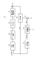
図1に本実施形態の回路装置20の第1の構成例を示す。集積回路装置である回路装置20は、制御電圧入力端子TVCと、A/D変換回路40と、処理回路50と、発振信号生成回路70を含む。また回路装置20は温度センサー30を含むことができる。なお図1では温度センサー30を回路装置20に内蔵しているが、温度センサー30を回路装置20の外部に設けてもよい。この場合には、外部の温度センサー30からの温度検出電圧VTDが入力される不図示の温度検出電圧入力端子を回路装置20に設ければよい。或いは、このような温度検出電圧入力端子を設けると共に温度センサー30を回路装置20に内蔵する構成としてもよい。
また負荷容量CLは下式(2)のように表すことができる。
上式(1)、(2)により下式(3)、(4)が成立する。
ERR=(CV×CT)/(C0×CV+C0×CT+CV×CT) (4)
ERRは誤差成分に相当する。また制御電圧VCと可変容量キャパシター75の容量CVとの間、及び温度補正電圧TCと可変容量キャパシター76の容量CTとの間には、例えば下式(5)、(6)の関係が成り立つ。
TC∝1/CT (6)
図4に比較例の構成での温度補正電圧TCと周波数偏差Δfの関係を示す。例えば、誤差成分ERRが定数であると仮定すると、上式(3)、(5)、(6)から下式(7)が成立する。
従って、制御電圧VCを定数とした場合には、周波数偏差Δfは温度補正電圧TCの一次関数になり、周波数偏差Δfと温度補正電圧TCの間には線形の関係が成り立つ。即ち、この場合には、温度補正電圧TCと周波数偏差Δfの関係は、図4のidealと記載された実線の特性に示すように線形の関係になる。しかしながら、実際には誤差成分ERRは定数ではなく、容量CV、CTに応じた値になり、例えば容量CTは温度補正電圧TCに応じて変化するため、誤差成分ERRも温度補正電圧TCに応じて変化してしまう。このため、図4の点線の特性に示すように理想的な線形の関係からのズレが生じる。このような誤差成分ERRを原因とする線形な関係からのズレが原因で、周波数温度特性の悪化の問題が発生する。なお本実施形態の第2の比較例として、周波数調整用の可変容量キャパシター75と温度補正用の可変容量キャパシター76を、振動子10とGNDノードとの間に並列に設ける構成も考えられる。しかしながら、この第2の比較例では、周波数偏差がΔf∝1/(C0+CV+CT)となるため、理想的な線形の関係からのズレが、図3の比較例の構成よりも更に大きくなってしまい、周波数温度特性が更に悪化する。
このような構成のフラクショナル-N型PLL回路82を用いることで、N+L/Mで表される分周比で発振信号OSCKを逓倍した発振信号OUTを生成できるようになる。
図11に本実施形態の回路装置20のレイアウト配置例を示す。回路装置20は辺SD1、SD2、SD3、SD4を有する。即ち回路装置10は、辺SD1、辺SD1の対辺である辺SD2、辺SD1に交差する辺SD3、及び辺SD3の対辺である辺SD4を有する。これらの辺SD1、SD2、SD3、SD4により矩形形状が形成される。辺SD1、SD2、SD3、SD4は、各々、第1の辺、第2の辺、第3の辺、第4の辺である。例えば辺SD1と辺SD2は互いに対向する辺であり、辺SD3、SD4は、辺SD1、SD2に直交し、且つ、互いに対向する辺である。ここで辺SD1から辺SD2に向かう方向をDR1とし、辺SD3から辺SD4に向かう方向をDR2とする。またDR2の反対方向をDR3とし、DR1の反対方向をDR4とする。方向DR1、DR2、DR3、DR4は、各々、第1の方向、第2の方向、第3の方向、第4の方向である。
図13に発振回路80の構成例を示す。図13はコルピッツ型の発振回路80の例である。可変容量キャパシター74は、振動子10の一端のノードNA1とGNDノードとの間に設けられる。振動子10の他端のノードNA2はバイポーラートランジスターBTRのベースに接続される。高電位側電源ノードであるVDDノードとバイポーラートランジスターBTRのコレクターとの間には抵抗RA1が設けられ、バイポーラートランジスターBTRのエミッターとGNDノードとの間には抵抗RA2が設けられる。VDDノードとノードNA2と間には抵抗RA3が設けられ、ノードNA2とGNDノードとの間には抵抗RA4が設けられる。またノードNA2とGNDノードの間にはキャパシターCA1、CA2が直列に設けられ、キャパシターCA1、CA2の接続ノードNA3とバイポーラートランジスターBTRのエミッターのノードNA4との間にはフィルターFLTが設けられる。なお発振回路80は、図13の構成には限定されず、その接続構成を異ならせるなどの種々の変形実施が可能である。また発振回路80としてピアーツ型などの発振回路を用いてもよい。
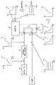
図14に、本実施形態の回路装置20を含む発振器400の構成例を示す。図14に示すように発振器400は、振動子10と回路装置20を含む。振動子10と回路装置20は、発振器400のパッケージ410内に実装される。そして振動子10の端子と、回路装置20の端子であるICのパッドは、パッケージ410の内部配線により電気的に接続される。図14では、発振器400はオーブン構造の発振器となっている。具体的にはダブルオーブン構造の発振器となっている。
図15に、本実施形態の回路装置20を含む電子機器500の構成例を示す。電子機器500は、本実施形態の回路装置20、振動子10、処理部520を含む。また電子機器500は、アンテナANT、通信部510、操作部530、表示部540、記憶部550を含むことができる。振動子10と回路装置20により発振器400が構成される。なお電子機器500は図15の構成に限定されず、これらの一部の構成要素を省略したり、他の構成要素を追加するなどの種々の変形実施が可能である。
OUT…発振信号、VC…制御電圧、VTD…温度検出電圧、DFC…発振制御信号、
ADQ…A/D変換データ、OSCK…発振信号、DIV…分周比データ、
TIF…インターフェース端子、C0…等価容量、CL…負荷容量、CT、CV…容量、
SD1、SD2、SD3、SD4…辺、DR1、DR2、DR3、DR4…方向、
10…振動子、20…回路装置、30…温度センサー、32…温度補正電圧生成回路、
40…A/D変換回路、50…処理回路、52…温度補正部、54…加算器、
56…補正処理部、57…変換処理部、70…発振信号生成回路、72…D/A変換回路、
74、75、76…可変容量キャパシター、80…発振回路、
82…フラクショナル-N型PLL回路、83…分周回路、84…位相比較器、
85…チャージポンプ回路、86…ローパスフィルター、87…電圧制御発振回路、
88…クロック生成回路、89…デルタシグマ変調回路、91…加減算回路、
100…電源回路、110…PLL回路、120…オーブン制御回路、130…メモリー
206…自動車、207…車体、208…制御装置、209…車輪、
400…発振器、410 パッケージ、411…基板、412…ケース、
413…第1の容器、414…第2の容器、416…基板、
450、452…ヒーター、460、462…温度センサー、
500…電子機器、510…通信部、520…処理部、
530…操作部、540…表示部、550…記憶部、
Claims (13)
- 制御電圧が入力される制御電圧入力端子と、
前記制御電圧をA/D変換して制御電圧データを生成し、温度センサーからの温度検出電圧をA/D変換して温度検出データを生成するA/D変換回路と、
前記温度検出データに基づいて発振周波数の温度補正データを生成し、前記温度補正データと前記制御電圧データの加算処理を行って、前記発振周波数の周波数制御データを生成する処理回路と、
前記周波数制御データと振動子を用いて、前記周波数制御データにより設定される前記発振周波数の発振信号を生成する発振信号生成回路と、
を含み、
回路装置は、第1の辺、前記第1の辺の対辺である第2の辺、前記第1の辺に交差する第3の辺、及び前記第3の辺の対辺である第4の辺を有し、
前記第1の辺から前記第2の辺に向かう方向を第1の方向とし、前記第3の辺から前記第4の辺に向かう方向を第2の方向としたときに、
前記発振信号生成回路は、前記A/D変換回路の前記第1の方向側に配置され、
前記処理回路は、前記A/D変換回路及び前記発振信号生成回路の前記第2の方向側に配置され、
前記A/D変換回路は、前記第2の辺からの距離に比べて前記第1の辺からの距離の方が近い位置に配置され、
前記発振信号生成回路は、前記第1の辺からの距離に比べて前記第2の辺からの距離の方が近い位置に配置されることを特徴とする回路装置。 - 請求項1に記載の回路装置において、
前記処理回路は、
前記加算処理の加算結果データに対して補正処理を行って、前記補正処理後の前記周波数制御データを出力し、
前記発振信号生成回路は、
前記補正処理後の前記周波数制御データをD/A変換して容量制御電圧を出力するD/A変換回路と、
前記容量制御電圧に基づいて容量が制御される可変容量キャパシターと、
前記可変容量キャパシターの前記容量を負荷容量として前記振動子を発振させて、前記発振信号を生成する発振回路と、
を含むことを特徴とする回路装置。 - 請求項1に記載の回路装置において、
前記処理回路は、
前記加算処理の加算結果データに対して変換処理を行って、前記変換処理後の前記周波数制御データとして分周比データを出力し、
前記発振信号生成回路は、
前記振動子を発振させて第2の発振信号を生成する発振回路と、
前記分周比データに基づき分周比が設定される分周回路を有し、前記分周回路からの分周クロック信号と前記第2の発振信号の位相比較を行って、前記発振信号を生成するフラクショナル-N型PLL回路と、
を含むことを特徴とする回路装置。 - 請求項1乃至3のいずれか一項に記載の回路装置において、
前記A/D変換回路と前記発振信号生成回路との間に電源回路が配置されることを特徴
とする回路装置。 - 請求項4に記載の回路装置において、
前記電源回路は、第1の電源電圧を前記A/D変換回路に供給し、第2の電源電圧を前記処理回路に供給し、第3の電源電圧を前記発振信号生成回路に供給することを特徴とする回路装置。 - 請求項1乃至5のいずれか一項に記載の回路装置において、
前記処理回路が用いるデータを記憶するメモリーを含み、
前記メモリーは、前記処理回路と前記第4の辺との間に配置されることを特徴とする回路装置。 - 請求項1乃至6のいずれか一項に記載の回路装置において、
前記処理回路に電気的に接続されるデジタルインターフェース端子を含み、
前記デジタルインターフェース端子は、前記処理回路と前記第4の辺との間に配置されることを特徴とする回路装置。 - 請求項1乃至7のいずれか一項に記載の回路装置において、
前記発振信号をバッファリングして外部に出力するバッファー回路を含み、
前記第2の方向の反対方向を第3の方向としたときに、前記バッファー回路は、前記発振信号生成回路の前記第3の方向側に配置されることを特徴とする回路装置。 - 請求項1乃至8のいずれか一項に記載の回路装置において、
前記振動子の温度を制御するオーブン制御回路を含み、
前記第2の方向の反対方向を第3の方向としたときに、前記オーブン制御回路は、前記A/D変換回路の前記第3の方向側に配置されることを特徴とする回路装置。 - 請求項1乃至9のいずれか一項に記載の回路装置において、
前記発振信号を逓倍したクロック信号を生成して出力するPLL回路を含み、
前記第2の方向の反対方向を第3の方向としたときに、前記PLL回路は、前記A/D変換回路の前記第3の方向側に配置されることを特徴とする回路装置。 - 請求項1乃至10のいずれか一項に記載の回路装置と、
前記振動子と、
を含むことを特徴とする発振器。 - 請求項1乃至10のいずれか一項に記載の回路装置を含むことを特徴とする電子機器。
- 請求項1乃至10のいずれか一項に記載の回路装置を含むことを特徴とする移動体。
Priority Applications (4)
| Application Number | Priority Date | Filing Date | Title |
|---|---|---|---|
| JP2018082716A JP7124417B2 (ja) | 2018-04-24 | 2018-04-24 | 回路装置、発振器、電子機器及び移動体 |
| TW108113717A TWI795556B (zh) | 2018-04-24 | 2019-04-19 | 電路裝置、振盪器、電子機器及移動體 |
| CN201910323650.2A CN110401415B (zh) | 2018-04-24 | 2019-04-22 | 电路装置、振荡器、电子设备和移动体 |
| US16/391,460 US10771011B2 (en) | 2018-04-24 | 2019-04-23 | Circuit device, oscillator, electronic apparatus, and vehicle |
Applications Claiming Priority (1)
| Application Number | Priority Date | Filing Date | Title |
|---|---|---|---|
| JP2018082716A JP7124417B2 (ja) | 2018-04-24 | 2018-04-24 | 回路装置、発振器、電子機器及び移動体 |
Publications (3)
| Publication Number | Publication Date |
|---|---|
| JP2019193052A JP2019193052A (ja) | 2019-10-31 |
| JP2019193052A5 JP2019193052A5 (ja) | 2021-04-30 |
| JP7124417B2 true JP7124417B2 (ja) | 2022-08-24 |
Family
ID=68238376
Family Applications (1)
| Application Number | Title | Priority Date | Filing Date |
|---|---|---|---|
| JP2018082716A Active JP7124417B2 (ja) | 2018-04-24 | 2018-04-24 | 回路装置、発振器、電子機器及び移動体 |
Country Status (4)
| Country | Link |
|---|---|
| US (1) | US10771011B2 (ja) |
| JP (1) | JP7124417B2 (ja) |
| CN (1) | CN110401415B (ja) |
| TW (1) | TWI795556B (ja) |
Families Citing this family (2)
| Publication number | Priority date | Publication date | Assignee | Title |
|---|---|---|---|---|
| US11519948B2 (en) * | 2019-05-17 | 2022-12-06 | Tokyo Electron Limited | Measuring device and method |
| JP7451959B2 (ja) | 2019-11-22 | 2024-03-19 | セイコーエプソン株式会社 | 振動デバイス、電子機器および移動体 |
Citations (6)
| Publication number | Priority date | Publication date | Assignee | Title |
|---|---|---|---|---|
| JP2000509219A (ja) | 1996-04-22 | 2000-07-18 | モトローラ・インコーポレイテッド | 温度補償および周波数逓倍機能を備えた周波数シンセサイザおよびその製造方法 |
| JP2003069426A (ja) | 2001-08-23 | 2003-03-07 | Matsushita Electric Ind Co Ltd | 周波数シンセサイザー |
| JP2004304332A (ja) | 2003-03-28 | 2004-10-28 | Mitsumi Electric Co Ltd | 発振回路 |
| JP2013211654A (ja) | 2012-03-30 | 2013-10-10 | Seiko Epson Corp | 発振器、電子機器及び発振器の温度補償方法 |
| JP2017092745A (ja) | 2015-11-12 | 2017-05-25 | セイコーエプソン株式会社 | 回路装置、発振器、電子機器及び移動体 |
| JP2017123631A (ja) | 2016-01-06 | 2017-07-13 | セイコーエプソン株式会社 | 回路装置、発振器、電子機器及び移動体 |
Family Cites Families (13)
| Publication number | Priority date | Publication date | Assignee | Title |
|---|---|---|---|---|
| JPH01265707A (ja) | 1988-04-18 | 1989-10-23 | Nec Corp | デジタル制御温度補償型圧電発振装置 |
| JPH0330518A (ja) | 1989-06-28 | 1991-02-08 | Hitachi Ltd | 位相同期発振器 |
| JP3050146B2 (ja) * | 1996-11-28 | 2000-06-12 | 日本電気株式会社 | デジタル温度補償発振器 |
| JPH1117450A (ja) * | 1997-06-20 | 1999-01-22 | Citizen Watch Co Ltd | 温度補償型水晶発振器 |
| US7436227B2 (en) * | 2003-05-02 | 2008-10-14 | Silicon Laboratories Inc. | Dual loop architecture useful for a programmable clock source and clock multiplier applications |
| KR100913974B1 (ko) * | 2006-02-23 | 2009-08-25 | 내셔널 세미콘덕터 코포레이션 | 선형성 정정 기능을 가지는 주파수비 디지털화 온도 센서 |
| US9092730B2 (en) * | 2011-08-11 | 2015-07-28 | Greenray Industries, Inc. | Neural network frequency control and compensation of control voltage linearity |
| CN202818228U (zh) * | 2012-10-16 | 2013-03-20 | 西安深亚电子有限公司 | 高精度数字温度补偿型晶体振荡器 |
| KR20140094095A (ko) * | 2013-01-21 | 2014-07-30 | 삼성전자주식회사 | 온도 제어 발진기 및 이를 포함하는 온도 센서 |
| JP5556928B2 (ja) | 2013-04-30 | 2014-07-23 | セイコーエプソン株式会社 | 温度補償電圧発生回路、温度補償型発振回路 |
| TWI551036B (zh) * | 2013-08-22 | 2016-09-21 | 瑞昱半導體股份有限公司 | 振盪頻率偏移偵測方法以及振盪頻率偏移偵測電路 |
| JP6561482B2 (ja) | 2015-02-04 | 2019-08-21 | セイコーエプソン株式会社 | 発振器、電子機器及び移動体 |
| US10177770B2 (en) * | 2016-01-06 | 2019-01-08 | Seiko Epson Corporation | Circuit device, oscillator, electronic apparatus, and vehicle |
-
2018
- 2018-04-24 JP JP2018082716A patent/JP7124417B2/ja active Active
-
2019
- 2019-04-19 TW TW108113717A patent/TWI795556B/zh active
- 2019-04-22 CN CN201910323650.2A patent/CN110401415B/zh active Active
- 2019-04-23 US US16/391,460 patent/US10771011B2/en active Active
Patent Citations (6)
| Publication number | Priority date | Publication date | Assignee | Title |
|---|---|---|---|---|
| JP2000509219A (ja) | 1996-04-22 | 2000-07-18 | モトローラ・インコーポレイテッド | 温度補償および周波数逓倍機能を備えた周波数シンセサイザおよびその製造方法 |
| JP2003069426A (ja) | 2001-08-23 | 2003-03-07 | Matsushita Electric Ind Co Ltd | 周波数シンセサイザー |
| JP2004304332A (ja) | 2003-03-28 | 2004-10-28 | Mitsumi Electric Co Ltd | 発振回路 |
| JP2013211654A (ja) | 2012-03-30 | 2013-10-10 | Seiko Epson Corp | 発振器、電子機器及び発振器の温度補償方法 |
| JP2017092745A (ja) | 2015-11-12 | 2017-05-25 | セイコーエプソン株式会社 | 回路装置、発振器、電子機器及び移動体 |
| JP2017123631A (ja) | 2016-01-06 | 2017-07-13 | セイコーエプソン株式会社 | 回路装置、発振器、電子機器及び移動体 |
Also Published As
| Publication number | Publication date |
|---|---|
| CN110401415A (zh) | 2019-11-01 |
| US20190326855A1 (en) | 2019-10-24 |
| JP2019193052A (ja) | 2019-10-31 |
| TW201946389A (zh) | 2019-12-01 |
| CN110401415B (zh) | 2023-07-04 |
| TWI795556B (zh) | 2023-03-11 |
| US10771011B2 (en) | 2020-09-08 |
Similar Documents
| Publication | Publication Date | Title |
|---|---|---|
| CN107040208B (zh) | 电路装置、振荡器、电子设备以及移动体 | |
| CN106953633B (zh) | 电路装置、振荡器、电子设备以及移动体 | |
| US10177770B2 (en) | Circuit device, oscillator, electronic apparatus, and vehicle | |
| CN107040209B (zh) | 电路装置、振荡器、电子设备以及移动体 | |
| CN106953631B (zh) | 电路装置、振荡器、电子设备以及移动体 | |
| CN107306132B (zh) | 电路装置、振荡器、电子设备以及移动体 | |
| CN107306134B (zh) | 电路装置、振荡器、电子设备以及移动体 | |
| JP2020170910A (ja) | Lvdsドライバー回路、集積回路装置、発振器、電子機器及び移動体 | |
| JP7009813B2 (ja) | 振動デバイス、電子機器及び移動体 | |
| JP7124417B2 (ja) | 回路装置、発振器、電子機器及び移動体 | |
| JP2017199946A (ja) | 回路装置、発振器、電子機器及び移動体 | |
| JP2017123629A (ja) | 回路装置、発振器、電子機器及び移動体 | |
| CN106961251B (zh) | 电路装置、振荡器、电子设备以及移动体 | |
| US11115029B2 (en) | Integrated circuit device, oscillator, electronic apparatus, and vehicle | |
| CN111200399B (zh) | 电路装置、电源电路、振荡器、电子设备及移动体 | |
| US11095250B2 (en) | Circuit device, oscillator, electronic apparatus, and vehicle | |
| JP7408950B2 (ja) | 回路装置、発振器、リアルタイムクロック装置、電子機器及び移動体 | |
| US10680554B2 (en) | Circuit device, oscillator, electronic apparatus, and vehicle | |
| JP2020039102A (ja) | 回路装置、発振器、電子機器及び移動体 | |
| JP2019012873A (ja) | 振動デバイス、電子機器及び移動体 | |
| JP2023127679A (ja) | 発振器 | |
| JP2023096335A (ja) | 発振器 |
Legal Events
| Date | Code | Title | Description |
|---|---|---|---|
| A521 | Request for written amendment filed |
Free format text: JAPANESE INTERMEDIATE CODE: A523 Effective date: 20210311 |
|
| A621 | Written request for application examination |
Free format text: JAPANESE INTERMEDIATE CODE: A621 Effective date: 20210311 |
|
| A977 | Report on retrieval |
Free format text: JAPANESE INTERMEDIATE CODE: A971007 Effective date: 20211223 |
|
| A131 | Notification of reasons for refusal |
Free format text: JAPANESE INTERMEDIATE CODE: A131 Effective date: 20220118 |
|
| A521 | Request for written amendment filed |
Free format text: JAPANESE INTERMEDIATE CODE: A523 Effective date: 20220309 |
|
| TRDD | Decision of grant or rejection written | ||
| A01 | Written decision to grant a patent or to grant a registration (utility model) |
Free format text: JAPANESE INTERMEDIATE CODE: A01 Effective date: 20220712 |
|
| A61 | First payment of annual fees (during grant procedure) |
Free format text: JAPANESE INTERMEDIATE CODE: A61 Effective date: 20220725 |
|
| R150 | Certificate of patent or registration of utility model |
Ref document number: 7124417 Country of ref document: JP Free format text: JAPANESE INTERMEDIATE CODE: R150 |