JP6992055B2 - Tools and tool machines and methods for machining plate features - Google Patents
Tools and tool machines and methods for machining plate features Download PDFInfo
- Publication number
- JP6992055B2 JP6992055B2 JP2019514020A JP2019514020A JP6992055B2 JP 6992055 B2 JP6992055 B2 JP 6992055B2 JP 2019514020 A JP2019514020 A JP 2019514020A JP 2019514020 A JP2019514020 A JP 2019514020A JP 6992055 B2 JP6992055 B2 JP 6992055B2
- Authority
- JP
- Japan
- Prior art keywords
- tool
- stroke
- axis
- workpiece
- machining
- Prior art date
- Legal status (The legal status is an assumption and is not a legal conclusion. Google has not performed a legal analysis and makes no representation as to the accuracy of the status listed.)
- Active
Links
Images


Classifications
-
- B—PERFORMING OPERATIONS; TRANSPORTING
- B21—MECHANICAL METAL-WORKING WITHOUT ESSENTIALLY REMOVING MATERIAL; PUNCHING METAL
- B21D—WORKING OR PROCESSING OF SHEET METAL OR METAL TUBES, RODS OR PROFILES WITHOUT ESSENTIALLY REMOVING MATERIAL; PUNCHING METAL
- B21D28/00—Shaping by press-cutting; Perforating
- B21D28/24—Perforating, i.e. punching holes
- B21D28/34—Perforating tools; Die holders
-
- B—PERFORMING OPERATIONS; TRANSPORTING
- B21—MECHANICAL METAL-WORKING WITHOUT ESSENTIALLY REMOVING MATERIAL; PUNCHING METAL
- B21D—WORKING OR PROCESSING OF SHEET METAL OR METAL TUBES, RODS OR PROFILES WITHOUT ESSENTIALLY REMOVING MATERIAL; PUNCHING METAL
- B21D19/00—Flanging or other edge treatment, e.g. of tubes
- B21D19/08—Flanging or other edge treatment, e.g. of tubes by single or successive action of pressing tools, e.g. vice jaws
-
- B—PERFORMING OPERATIONS; TRANSPORTING
- B21—MECHANICAL METAL-WORKING WITHOUT ESSENTIALLY REMOVING MATERIAL; PUNCHING METAL
- B21D—WORKING OR PROCESSING OF SHEET METAL OR METAL TUBES, RODS OR PROFILES WITHOUT ESSENTIALLY REMOVING MATERIAL; PUNCHING METAL
- B21D28/00—Shaping by press-cutting; Perforating
- B21D28/02—Punching blanks or articles with or without obtaining scrap; Notching
- B21D28/12—Punching using rotatable carriers
- B21D28/125—Punching using rotatable carriers with multi-tools
-
- B—PERFORMING OPERATIONS; TRANSPORTING
- B21—MECHANICAL METAL-WORKING WITHOUT ESSENTIALLY REMOVING MATERIAL; PUNCHING METAL
- B21D—WORKING OR PROCESSING OF SHEET METAL OR METAL TUBES, RODS OR PROFILES WITHOUT ESSENTIALLY REMOVING MATERIAL; PUNCHING METAL
- B21D35/00—Combined processes according to or processes combined with methods covered by groups B21D1/00 - B21D31/00
- B21D35/001—Shaping combined with punching, e.g. stamping and perforating
Description
本発明は好ましくは板金である板状工作物の加工のための工具および工具機械並びに方法に関する。 The present invention relates to tools, tool machines and methods for machining plate-like workpieces, preferably sheet metal.
このような工具機械は欧州特許第2527058号明細書から公知である。この出版物は工作物の加工のための加圧機の形の工具機械を開示し、上部工具が加工されるべき工作物に対してストローク軸に沿って工作物への方向および反対方向に移動可能なストローク装置に設けられる。ストローク軸の中および上部工具に向き合って下側に位置する下部工具が設けられる。上部工具のストローク運動のためのストローク駆動装置が楔ギアによって制御される。それに配置された上部工具を有するストローク駆動装置がモータ駆動により位置付け軸に渡って移動可能である。下部工具はモータ駆動と同期的に上部工具に移動する。 Such tool machines are known from European Patent No. 2527058. This publication discloses a tool machine in the form of a pressurizer for machining the feature, allowing the upper tool to move in and out of the stroke axis with respect to the feature to be machined. It is provided in a stroke device. A lower tool located in the stroke axis and on the lower side facing the upper tool is provided. The stroke drive device for the stroke movement of the upper tool is controlled by the wedge gear. A stroke drive device with an upper tool placed on it can be moved across the positioning shaft by motor drive. The lower tool moves to the upper tool in synchronization with the motor drive.
独国特許出願公開第102006049044号明細書から、例えば欧州特許第2527058号明細書の工具機械の中で使用可能な板状工作物の加工のための工具が公知である。この板状工作物の切断および/または変形のための工具は、打ち抜きスタンプおよび打ち抜き鋳型を含む。打ち抜きスタンプと打ち抜き鋳型の間に配置された工作物を加工するために、これらは互いに対してストローク方向に向かって動く。打ち抜きスタンプには切断縁部を有する切断工具が配置され、打ち抜き鋳型には少なくとも2つの対抗切断縁部が設けられる。打ち抜きスタンプおよび打ち抜き鋳型は、互いに相関して共有の位置付け軸を中心に回動可能である。そのとき対抗切断縁部は、打ち抜きスタンプの切断工具の回動運動により切断工具の切断縁部が対抗切断縁部に対して位置付けられるように、共有の位置付け軸に配向される。対抗切断縁部は位置付け軸への間隔において切断縁部の共有の位置付け軸への間隔に相応する。 From German Patent Application Publication No. 102006049044, tools for machining plate-like workpieces that can be used, for example, in the tool machine of European Patent No. 2527058 are known. Tools for cutting and / or deformation of this plate feature include punching stamps and punching molds. To machine the workpieces placed between the stamp and the punching mold, they move in the stroke direction with respect to each other. A cutting tool having a cutting edge is arranged on the punching stamp, and the punching mold is provided with at least two counter-cutting edges. The punching stamp and the punching mold are rotatable around a shared positioning axis that correlates with each other. At that time, the counter-cutting edge portion is oriented to the common positioning axis so that the cutting edge portion of the cutting tool is positioned with respect to the counter-cutting edge portion by the rotational movement of the cutting tool of the punching stamp. The counter-cutting edge corresponds to the spacing of the cutting edge to the shared positioning axis in the spacing to the positioning axis.
欧州特許第2177289号明細書からさらに板状工作物の切断および/または変形のための工具が公知である。この工具はまたも互いに対して共有の位置付け軸に配向された打ち抜きスタンプおよび打ち抜き鋳型を含む。打ち抜きスタンプはこの位置付け軸を中心に回動可能に軸支されるため、切断工具の少なくとも1つの切断縁部が打ち抜きスタンプで打ち抜き鋳型の少なくとも1つの対抗切断縁部に配向されることができる。打ち抜き鋳型は、工作物用の台面の中にそれを通して分離した工作物部品が排出され得る開口部を含む。開口部に隣接してもう1つの対抗切断縁部が設けられ、それは位置付け軸に対してもう1つの対抗切断縁部が開口部で有するものと同じ間隔を有する。開口部の外にある打ち抜き鋳型の対抗切断縁部には、板金の排出面が設けられる。この工具の場合も対抗切断縁部の位置付け軸への間隔は、打ち抜きスタンプの切断工具の切断縁部の位置付け軸への間隔に相応する。 Further known from European Patent No. 2177289 are tools for cutting and / or deforming plate features. This tool also includes punching stamps and punching molds oriented to a positioning axis shared with each other. Since the punched stamp is rotatably supported around this positioning axis, at least one cutting edge of the cutting tool can be oriented with the punching stamp to at least one counter-cutting edge of the punching die. The punching mold contains an opening in the geographic surface for the workpiece through which the separated workpiece parts can be ejected. Adjacent to the opening is another counter-cutting edge, which has the same spacing as that the other counter-cutting edge has at the opening with respect to the positioning axis. A sheet metal discharge surface is provided at the counter-cutting edge of the punching mold outside the opening. In the case of this tool as well, the distance of the counter-cutting edge to the positioning shaft corresponds to the distance of the cutting tool of the punching stamp to the positioning shaft.
国際公開第02/043892号から、上部および下部工具を有する板状工作物の切断のための工具が公知である。上部工具は共有の位置付け軸中にあるクランプシャフトおよび基体を含む。基体にはクランプシャフトに向き合う加工工具が設けられる。下部工具は工作物用の台面を有する基体および台面内にある開口部を含む。加工工具の切断縁部は縦溝をもたらすために工作物の面に対して傾斜して配向される。 From International Publication No. 02/043892, tools for cutting plate-shaped workpieces having upper and lower tools are known. Top tools include clamp shafts and substrates that are in a shared positioning shaft. The substrate is provided with a machining tool facing the clamp shaft. The lower tool includes a substrate with a geographic feature for the workpiece and an opening in the countertop. The cutting edge of the feature is tilted and oriented with respect to the surface of the workpiece to provide a flute.
本発明は工作物の加工における柔軟性を向上する、板状工作物の切断および/または変形のための工具および工具機械並びに方法を提案することを課題とする。 It is an object of the present invention to propose tools, tool machines and methods for cutting and / or deforming plate features that improve flexibility in machining the features.
この課題は請求項1の特徴を有する特に板金である板状工作物の切断および/または変形のための工具によって解決される。
This problem is solved by a tool for cutting and / or deforming a plate-shaped workpiece, which is particularly sheet metal and has the characteristics of
板状工作物の加工のための工具は工作物上に作用する加工工具を有し、その場合加工工具を受ける工具体が工具回動軸あるいは上部工具の位置付け軸に対して傾斜する長手軸を有する。この加工工具は好ましくは上部工具に設けられる。それによってY方向およびZ方向への移動が制御可能である上部工具のストローク運動の制御により、垂直なストローク運動から逸脱した特に傾斜したストローク運動が実施され得る。そのような傾斜して推移するストローク運動により工作物または工作物縁部で斜めの切断が成形され得ることが実現される。これは例えば傾斜した部分縁部の製作を可能にする。同様に工作物での溶接縁部準備が設けられることができる。そのことから工作物面に対して突起した下向きあるいは上向きのフランジでは加工、特に打ち抜きストロークが行われ得ることが可能になる。そのようなフランジでは直角の部分縁部、または傾斜した部分縁部がもたらされることができる。そのことから位置付け軸に向かって傾斜した工具体により、例えば曲げ刻印または変形のようなさらなる加工が可能になる。 The tool for machining a plate-like workpiece has a machining tool that acts on the workpiece, in which case the tool body that receives the machining tool has a longitudinal axis that is tilted with respect to the tool rotation axis or the positioning axis of the upper tool. Have. This machining tool is preferably provided on the upper tool. By controlling the stroke motion of the upper tool, which can control the movement in the Y and Z directions, a particularly tilted stroke motion deviating from the vertical stroke motion can be performed. It is realized that an oblique cut can be formed at the workpiece or the edge of the workpiece by such an inclined transition stroke motion. This allows, for example, the production of sloping partial edges. Similarly, weld edge preparation in the workpiece can be provided. This makes it possible to perform machining, especially punching strokes, with downward or upward flanges protruding from the surface of the workpiece. Such flanges can result in right-angled partial edges, or sloping partial edges. As such, the tool body tilted towards the positioning axis allows for further machining such as bending markings or deformations.
工具体の長手軸の傾斜により工作物の切断面のための配向が決定され得る。好ましくは上部工具の下部工具へのストローク運動も、これが工具体の長手軸に渡って推移するように制御され得る。 The inclination of the longitudinal axis of the tool can determine the orientation for the cut surface of the workpiece. Preferably, the stroke motion of the upper tool to the lower tool can also be controlled so that it travels across the longitudinal axis of the tool body.
加工工具の長手軸が位置付け軸に対して90°までの角度で傾斜することが好ましく企図される。これは例えば工作物台面上に着座する工作物の場合、例えば工作物の台面に垂直に配向されうる工作物の前面または前側の加工も可能であることを実現する。 It is preferably contemplated that the longitudinal axis of the machining tool will tilt at an angle of up to 90 ° with respect to the positioning axis. This realizes that, for example, in the case of a geographic feature that sits on the geographic feature, it is possible to machine the front or front of the feature that can be oriented perpendicular to the geographic feature, for example.
加工工具の第1実施形態ではこれが切断工具として形成され、工具体の自由端に少なくとも1つの切断縁部を有することが企図される。そのような切断縁部の輪郭により、および打ち抜き鋳型の対抗切断縁部と連携して様々な切断輪郭または加工が実施され得る。 In the first embodiment of the machining tool, it is formed as a cutting tool and it is contemplated that it will have at least one cutting edge at the free end of the tool body. Various cutting contours or processes can be performed by such cutting edge contours and in conjunction with the counter-cutting edges of the punching mold.
好ましくは直角に工具体の長手軸に配向されたスタンプ面が好ましくは工具体に設けられ、少なくとも1つの切断縁部がスタンプ面に設けられる。有利には全スタンプ面が周囲を巡る切断縁部によって画定され得る。例えばスタンプ面に上部および下部の切断縁部、並びに上下にある切断縁部を接続する側方の切断縁部を備えたそのような工具体を使って、下部並びに上部の斜角面が工作物に簡単な方法でもたらされ得る。打ち抜き鋳型の対抗切断縁部が、下部工具の基体の台面にあることがさらに好ましく企図される。傾斜した工具基体を有する上部工具が打ち抜き鋳型の方に移動される限り、打ち抜き鋳型上に着座する工作物に傾斜した切断縁部が生成され得る。 A stamp surface oriented at a right angle to the longitudinal axis of the tool body is preferably provided on the tool body, and at least one cutting edge is provided on the stamp surface. Advantageously, the entire stamped surface may be defined by a peripheral cut edge. For example, with such a tool body with upper and lower cut edges on the stamp surface, as well as lateral cut edges connecting the upper and lower cut edges, the lower and upper bevels are workpieces. Can be brought to you in an easy way. It is more preferably contemplated that the counter-cutting edge of the punching die is on the base surface of the substrate of the lower tool. As long as the upper tool with the tilted tool substrate is moved towards the punching mold, a tilted cutting edge can be created on the workpiece seated on the punching mold.
対抗切断縁部に画定する支持面が下部工具の基体の台面に対して傾斜し、好ましくはこれに対して上部工具の方向に突起することが代替的に企図されうる。支持面の傾斜は有利にはスタンプ面の傾斜に相応する。支持面に垂直に配向されたストローク運動の場合、上向きの工作物部品に直角の部分縁部が製作されることができる。 Alternatively, it may be conceivable that the support surface defined at the counter-cutting edge is inclined with respect to the base surface of the lower tool substrate, preferably projecting in the direction of the upper tool. The slope of the support surface advantageously corresponds to the slope of the stamp surface. In the case of stroke motion oriented perpendicular to the support surface, a partial edge perpendicular to the upward workpiece part can be made.
対抗切断縁部に画定する工作物基体の長手軸に傾斜してまたは平行に形成される穴空け面が形成されることがさらに好ましく企図される。そのときストローク運動中の工具体の支持が可能であり得る。好ましくは穴空け面が工具体の長手軸に対して傾斜するため、穴空け面が工具体の増加する作業ストロークによってこれから分離される。 It is more preferably contemplated that a perforated surface formed inclined or parallel to the longitudinal axis of the workpiece substrate defined at the counter-cutting edge is formed. At that time, it may be possible to support the tool body during the stroke movement. Preferably, the perforated surface is tilted with respect to the longitudinal axis of the tool body, so that the perforated surface is separated from it by the increasing working stroke of the tool body.
工具のさらなる実施形態は、穴空け面に対して間隔を空けた対抗鋳型を設けることを企図する。そのとき間隔はストローク運動の間穴空け面と対抗鋳型の間に案内される工具体の厚さまたは大きさに適合することが企図される。そのような対抗鋳型によって、望ましくない工作物の打ち抜き鋳型の台面からの持ち上がりを防止できる。 A further embodiment of the tool contemplates providing counter-molds spaced apart from the perforated surface. The spacing is then intended to match the thickness or size of the tool body guided between the perforated surface of the stroke motion and the countermold. Such counter-molds can prevent unwanted workpieces from being lifted from the table surface of the punching mold.
対抗切断縁部に画定する打ち抜き鋳型の支持面は、好ましくは加工されるべき工作物のフランジの角度に適合する。それによってフランジ加工の間、それ以前にもたらされたフランジの角度が維持され得る。 The support surface of the punching mold defined at the counter-cutting edge preferably matches the angle of the flange of the workpiece to be machined. Thereby, during flange processing, the angle of the previously brought flange can be maintained.
工作物の代替的な実施形態ではこれが印字または刻印工具として形成される。印字または刻印工具の傾斜した配向により、工作物のフランジ上にまたは前面上に標識を付けることが企図され得る。 In an alternative embodiment of the feature this is formed as a printing or engraving tool. The tilted orientation of the printing or engraving tool may be intended to mark on the flange or on the front of the workpiece.
さらに代替的に工具が曲げおよび/または変形工具であることが企図される。それによって様々な輪郭が工作物にもたらされ得る。 Alternatively, it is conceivable that the tool is a bending and / or deforming tool. This can bring various contours to the feature.
工具のさらなる代替としてこれがエンボス加工工具を形成することが企図される。 As a further alternative to the tool, it is intended to form an embossed tool.
本発明の根底にある課題は、さらに板状工作物の加工のための工具機械によって解決され、その工具機械では上部工具の上部位置付け軸に沿った移動および下部工具の下部位置付け軸に沿った移動がそれぞれ互いから独立して制御可能であり、工作物の加工のために工具体が設けられ、その工具体では加工工具が上部工具の位置付け軸に対して傾斜する。工具機械により、Z軸の外にありY軸に沿った運動により重複され得る、上部工具および/または下部工具のストローク運動が制御され得る。それによって工作物の加工においても適用においても柔軟性が向上する。 The underlying problem of the present invention is further solved by a tool machine for machining plate features, in which the tool machine moves along the upper positioning axis of the upper tool and moves along the lower positioning axis of the lower tool. Can be controlled independently of each other, and a tool body is provided for machining the workpiece, in which the machining tool is tilted with respect to the positioning axis of the upper tool. The tool machine can control the stroke motion of the upper and / or lower tools that are outside the Z axis and can be overlapped by motion along the Y axis. This improves flexibility both in the processing and application of geographic features.
本発明の根底にある課題は、さらに板状工作物の加工のための方法によって解決され、その方法の場合、工具の位置付け軸に対して傾斜して配向された加工工具を有し、上部工具および/または下部工具がストローク軸の外にあるストローク運動によって制御される工具が適用される。それによって工作物の加工における多様性が向上することができる。 The underlying problem of the present invention is further solved by a method for machining plate features, which has a machining tool tilted and oriented with respect to the positioning axis of the tool and is an upper tool. And / or a tool whose lower tool is controlled by a stroke motion outside the stroke axis is applied. Thereby, the variety in the processing of the workpiece can be improved.
ストローク軸に対して傾斜する直線的なストローク運動を有する上部工具、および/または下部工具のストローク運動が制御されることが好ましく企図される。例えば工具体の長手軸に沿ったこの傾斜した直線的なストローク運動が、加工工具に配向されることができる。ストローク軸、特にZ軸に対して曲線型または円弧状のストローク運動が制御されることが代替的に企図され得る。下部工具への上部工具の移動に相応するパラメータにより、切断または剪断だけではなく面取りまたは変形も、丸みを帯びたまたは湾曲した輪郭によって達成され得る。 It is preferably contemplated that the stroke motion of the upper and / or lower tools having a linear stroke motion tilted with respect to the stroke axis is controlled. For example, this tilted linear stroke motion along the longitudinal axis of the tool body can be oriented to the machining tool. It may be alternatively attempted to control the curvilinear or arcuate stroke motion with respect to the stroke axis, in particular the Z axis. Depending on the parameters corresponding to the movement of the upper tool to the lower tool, not only cutting or shearing but also chamfering or deformation can be achieved by rounded or curved contours.
工作物の加工のためのさらなる実施形態は、上部工具がストローク軸に沿ったストローク運動により下部工具へ、および続いて上部位置付け軸に沿って移動し、ストローク運動およびそれに続く位置付け軸に沿った移動の間、下部工具が静止して位置を占めることを好ましく企図する。それによって例えば折りたたみ加工が工作物の切り抜かれた連結金属に行われ得る。それによってフランジも生成することができる。ストローク軸および位置付け軸に沿った移動ルートに応じてフランジのスイベル角度を調節できる。例えば上部工具の下部工具へのストローク運動によって90°折れたフランジが達成されたなら、それに続く上部位置付け軸に沿った移動はフランジのさらなる旋回運動を導入するため、連結金具またはフランジは工作物面に対して90°以上曲折され得る。 A further embodiment for machining the workpiece is that the upper tool moves to the lower tool by stroke motion along the stroke axis and subsequently along the upper positioning axis, and the stroke motion followed by movement along the positioning axis. It is preferably intended that the lower tool rests and occupies the position during the period. Thereby, for example, folding can be performed on the cut-out connecting metal of the workpiece. Thereby, a flange can also be generated. The swivel angle of the flange can be adjusted according to the movement route along the stroke axis and the positioning axis. For example, if a stroke motion of the upper tool to the lower tool achieves a flange that is bent 90 °, then subsequent movement along the upper positioning axis introduces further turning motion of the flange, so that the fitting or flange is the workpiece surface. Can be bent 90 ° or more with respect to.
上部および/または下部工具を工具の切れ目に対して調整し、あるいは打ち抜きスタンプの切断縁部と打ち抜き鋳型の対抗切断縁部の間の切れ目幅を調整するために、あるいは残余接続を分離するために調整するため、上部工具および/または下部工具が、それらの位置付け軸を中心とした回動運動および/またはそれぞれの位置付け軸に沿った移動によって制御されることが、さらに好ましく企図される。 To adjust the top and / or bottom tool to the tool cut, or to adjust the cut width between the cut edge of the punch stamp and the counter-cut edge of the punching mold, or to separate the residual connections. It is more preferably contemplated that the upper and / or lower tools are controlled by rotational movements around their positioning axes and / or movements along their respective positioning axes for adjustment.
本発明並びにそのさらなる有利な実施形態および発展形態は、以下で図面に示された例を参照して詳細に説明され解説される。説明および図面から得られる特徴は、本発明に従って個々にまたは任意の組み合わせで組み合わせて適用され得る。 The present invention and further advantageous embodiments and developments thereof will be described and described in detail with reference to the examples shown in the drawings below. The features obtained from the description and drawings may be applied individually or in any combination according to the present invention.
図1はスタンピングプレスとして形成された工具機械1を示す。この工具機械1は閉じた機械フレーム2を備えた支持構造を含む。この機械フレームは2本の水平フレーム脚3、4および2本の垂直フレーム脚5、6を含む。機械フレーム2は上部工具11および下部工具9を有する工具機械1の作業領域を成形するフレーム内部7を包括する。
FIG. 1 shows a
工具機械1は、簡略化のために図1には示されない、加工目的のためにフレーム内部7の中に配置され得る板状工作物10の加工のために使用される。加工されるべき工作物10は、フレーム内部7の中に設けられる工作物支持体8の上に載せられる。工作物支持体8の凹部の中で機械フレーム2の下部水平フレーム脚4に下部工具9が例えば打ち抜き鋳型の形で支持される。この打ち抜き鋳型には鋳型開口部を設けることができる。打ち抜き加工の際、打ち抜き鋳型として形成された下部工具の鋳型開口部の中に、打ち抜きスタンプとして形成された上部工具11が沈み込む。
The
上部工具11および下部工具9は、打ち抜きスタンプおよび打ち抜き鋳型の代わりに、曲げスタンプおよび曲げ鋳型としても工作物10の変形のために使用され得る。
The
上部工具11はタペット12の下端にある工具受けの中に固定される。タペット12は、それを使って上部工具11がストローク方向にストローク軸14に沿って移動され得るストローク駆動装置13の部分である。ストローク軸14は、図1で暗示される工具機械1の数値制御15の座標系のZ軸の方向に延びる。ストローク軸14に垂直にストローク駆動装置13が、位置付け軸16に渡って二重矢印の方向に移動され得る。位置付け軸16は数値制御15の座標系のY方向の方向に延びる。上部工具11を受けるストローク駆動装置13は、モータ駆動装置17を使って位置付け軸16に渡って移動する。
The
ストローク軸14に沿ったタペット12の運動および位置付け軸16に沿ったストローク駆動装置13の位置付けが、駆動装置17の形の、特に位置付け軸16の方向に延び、機械フレーム2と固定的に結合した駆動スピンドル18を有するスピンドル駆動装置17の形のモータ駆動装置17を使って行われる。ストローク駆動装置13は運動の際に、上部フレーム脚3の3本のガイドレール19の上を位置付け軸16に渡って案内される。それらのうちではガイドレール19が図1で識別され得る。1本の残りのガイドレール19は図示されるガイドレール19に並行して延び、これから数値制御装置15の座標系のX軸の方向に間隔を設ける。ガイドレール19上をストローク駆動装置13のガイドシュー20が移動する。ガイドレール19とガイドシュー20の相互の係合は、ガイドレール19とガイドシュー20の間のこの結合が垂直方向に作用する負荷をも受けることができるように形成される。それに相応してストローク装置13はガイドシュー20およびガイドレール19に渡って機械フレーム2に吊持される。ストローク駆動装置13のもう1つの構成要素は、それによって上部工具11の位置が下部工具9に関して調節可能になる楔ギア21である。
The movement of the
下部工具9は下部位置付け軸25に沿って移動可能に受けられる。この下部位置付け軸25は数値制御15の座標系のY軸の方向に延びる。好ましくは下部位置付け軸25は上部位置付け軸16に平行に配向される。下部工具9は直接下部位置付け軸16でモータ制御装置26によって位置付け軸25に沿って移動し得る。代替的または補完的に下部工具9は、下部位置付け軸25に沿ってモータ制御装置26を使って移動可能なストローク駆動装置27にも設けられる。この制御装置26は好ましくはスピンドル駆動装置として形成される。下部ストローク駆動装置27は上部ストローク駆動装置13の構造に相応し得る。同様にモータ制御装置26はモータ制御装置17に相応し得る。
The
下部ストローク駆動装置27は同様に下部水平フレーム脚4に割り当てられたガイドレール19に摺動可能に支持される。ガイドレール19上をストローク駆動装置27のガイドシュー20が移動するため、ガイドレール19とガイドシュー20の間の接続は、下部工具9で水平方向に作用する負荷をも受けることができる。それに相応してストローク駆動装置27もガイドシュー20およびガイドレール19に渡って機械フレーム2で、上部ストローク駆動装置13のガイドレール19およびガイドシュー20に対して間隔を空けて吊持される。ストローク駆動装置27も、それによって下部工具9のZ軸に沿った位置または高さを調節できる楔ギア21を含むことができる。
The lower
数値制御15によって、上部工具11の上部位置付け軸16に沿った移動のためのモータ駆動17も、下部工具9の下部位置付け軸25に沿った移動のための単数または複数のモータ駆動26も、互いから独立して制御され得る。それによって上部および下部工具11、9は同期的に座標系のY軸の方向に移動できる。同様に上部および下部工具11、9の独立した移動は異なる方向にも制御され得る。上部および下部工具11、9のこれらの独立した移動は同時に制御され得る。上部工具11と下部工具9の間の移動の連動解除により工作物10の加工の柔軟性の向上が達成される。工作物10の加工のための上部および下部工具11、9は多様なあり方でも形成され得る。
ストローク駆動装置13の構成要素は図2で示された楔ギア21である。楔ギア21は2つの入力側の楔ギア部材122、123および2つの出力側の楔ギア部材124、125を含む。後者は建設的に出力側の二重楔126の形の構造ユニットにまとめられている。出力側の二重楔126にはタペット12がストローク軸14の周りで回動可能に軸支される。モータ回転駆動装置128が出力側の二重楔126の中に格納され、タペット12を必要に応じてストローク軸14に沿って移動する。そのときタペット12の左回動も右回動も図2の二重楔によって可能である。タペット軸受129が概略的に示される。一方でタペット軸受129はタペット12のストローク軸14を中心とする摩擦の少ない回転運動を許し、もう一方でタペット軸受129はタペット12を軸方向に軸支し、相応にタペット12上でストローク軸14の方向に作用する負荷を出力側の二重楔126の中に搬出する。
The component of the
出力側の二重楔126は楔面130および出力側の駆動部材125の楔面131によって画定される。出力側の楔ギア駆動部材124、125の楔面130、131には、入力側の楔駆動部材122、123の楔面132、133が向き合う。縦ガイド134、135によって、入力側の楔駆動部材122および出力側の楔駆動部材124、並びに入力側の楔駆動部材123および出力側の楔駆動部材125が、Y軸の方向に、つまりストローク駆動装置13の位置付け軸16の方向に、互いに関して相対的に可動に案内される。
The output-side
入力側の楔ギア部材122はモータ駆動ユニット138を有し、入力側の楔駆動部材123はモータ駆動ユニット139を有する。両駆動ユニット138、139は共同でスピンドル駆動装置17を成形する。
The
モータ駆動ユニット138、139に共通であるのは、図1に示された駆動スピンドル18および機械フレーム2に軸支されその結果支持構造側のストローク駆動装置13、27である。
Common to the
モータ駆動ユニット138、139に対して入力側の楔駆動部材122、123が、これらが位置付け軸16に沿って例えば互いに向かって動き、それによって一方では入力側の楔駆動部材122、123間の、もう一方では出力側の楔駆動部材124、125間の相対運動が生じるように作動される。この相対運動の結果、出力側の二重楔126およびそれに支持されるタペット12が、ストローク軸14に沿って下方に動く。タペット12に例えば上部工具11として取り付けられた打ち抜きスタンプが作業ストロークを実施し、そのとき工作物台28、29または工作物支持体8上に置かれた工作物10を加工する。楔駆動部材122、123の互いに対して対抗する運動によって、タペット12はまたもストローク軸14に沿って持ち上げられまたは上方に動く。
With respect to the
前述の図2のストローク駆動装置13は好ましくは下部ストローク駆動装置27と同一に形成され下部工具9を受ける。
The
図3はタペット12の可能なストローク運動の概略表を示す。表はY軸およびZ軸に沿ったストロークの経過を示す。ストローク軸14および位置付け軸16に沿ったタペット12の移動の重複した制御は、例えばタペット12の下方に工作物10へと斜めに延びるストローク運動が、これが第1直線Aで示されるように制御され得る。それに続いてストロークの実施後タペット12は、例えば直線Bで示されるように、垂直に持ち上げられ得る。タペット12を工作物10への新しい作業位置に位置付けるために、続いて例えば直線CのY軸に沿った移動のみが行われる。それに続いて例えば前述した作業順序が繰り返され得る。後続の加工段階のために工作物10が工作物台面28、29上で移動される限り、直線Cに沿った移動も省略され得る。
FIG. 3 shows a schematic table of possible stroke movements of the
図3の表に示されたタペット12の上部工具11での可能なストローク運動は、好ましくは静止された下部工具9と組み合わされる。そのとき下部工具9は、上部工具11の作業ストロークの終わりに上部および下部工具11、9が定義された位置を占めるように機械フレーム2内に位置付けられる。
The possible stroke movement of the
この例示的に重複したストローク過程は、上部工具11のためにも下部工具9のためにも制御され得る。工作物10の行われるべき加工に応じて、上部工具および/または下部工具11、9の重複したストローク運動が制御され得る。
This exemplary overlapping stroke process can be controlled for both the
図4ではY軸およびZ軸に沿った例示的に示される線Dによってタペット12のストローク運動を示す概略表が示される。図3から逸脱してこの実施形態例では、Y方向およびZ方向への移動の重複が相応に制御15によって制御されることにより、タペット12のストローク運動が曲線状または円弧状の推移を辿り得ることが企図される。そのようなXおよびZ方向への移動の柔軟な重複によって、加工に固有の課題が解決される。そのような曲線的推移の制御が上部工具11および/または下部工具9のために企図され得る。
In FIG. 4, a schematic table showing the stroke motion of the
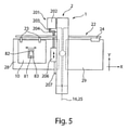
図5には図1の工具機械1の概略図が示される。工具機械1の機械フレーム2の側方にそれぞれ1つの工作物台28、29が延在する。工作物台28は、例えば詳細には示されない、それによって未加工の工作物10が工作物台28上に載せられる積載ステーションに割り当てられ得る。工作物台28、29に画定して工作物台28上に載せられた工作物10を把持するために、複数のグリップ23を含む送り装置22が設けられる。送り装置22を使って、工作物10はX方向に機械フレーム2を通して案内される。好ましくは送り装置22がY方向にも移動可能に制御され得る。それによって工作物10のX-Y面での自由な移動が企図され得る。作業課題に応じて工作物10は、送り装置22によってX方向にもX方向とは反対方向にも運動可能である。この工作物10の移動は、上部工具11および下部工具9のそれぞれの加工課題のための、Y方向へのおよびその反対方向への移動に適応することができる。
FIG. 5 shows a schematic view of the
工作物台28に向き合ってもう1つの工作物台29が機械フレーム2に設けられる。これは例えば荷下ろしステーションに割り当てられ得る。代替的に未加工の工作物10および工作物81を有する加工された工作物10の積載および荷降ろしも、同じ工作物台28、29に割り当てられ得る。
Another
工具機械1はさらにレーザ加工装置201、特に概略的にのみ図5の上面図に示されるレーザ切断機を有し得る。このレーザ加工装置201は例えばCO2レーザ切断機として形成され得る。レーザ加工装置201は、概略的に示された光線ガイド204を使ってレーザ加工ヘッド、特にレーザ切断ヘッド206に案内されその中に集束されるレーザ光線203を生成するレーザ源202を含む。その後レーザ光線204は、工作物10を加工するために切断ノズルにより、工作物10の表面に垂直に配向される。レーザ光線203は加工場所、特に切断場所で好ましくはプロセスガス流と共に工作物10に作用する。レーザ光線203が工作物10に発生する切断位置は、上部工具11および下部工具9の加工位置に隣接する。
The
レーザ切断ヘッド206は、リニア軸システムを有するリニア駆動207よって少なくともY方向に、好ましくはYおよびZ方向に移動可能である。レーザ切断ヘッド206を受けるこのリニア軸システムは機械フレーム2に割り当てられ、それに固定されまたはその中に統合され得る。レーザ切断ヘッド206の作業空間の下に、光線通路開口部が工作物台28中に設けられ得る。好ましくは光線通路開口部の下にレーザ光線21のための光線捕取装置が設けられ得る。光線通路開口部および場合により光線捕取装置は構造ユニットとして形成され得る。
The
レーザ加工装置201は、代替的にその光線が光配線の助けを借りてレーザ切断ヘッド206に案内される個体レーザもレーザ源202として備えることができる。
The
工作物台28、29は下部工具9が少なくとも部分的に包囲する工作物支持体8まで直接延在し得る。それらの間に生じる空間内で下部工具9が、下部位置付け軸25に沿ってY方向およびその反対方向に移動可能である。
The work bases 28, 29 may extend directly to the
工作物台28上に例えば加工された工作物10が載せられ、そこで工作物部品81が切れ目83から、例えば打ち抜き加工またはレーザ光線加工により、残留接続82以外は切り抜かれる。この残留接続により工作物81は、工作物10または残りの残留グリッドの中に保持される。工作物部品81を工作物10から分離するために、工作物10は送り装置22を使って上部および下部工具11、9に、打ち抜きおよび排出段階のために位置付けられる。そのとき残留接続82は上部工具11の下部工具9への打ち抜きストロークによって分離される。工作物部品81は例えば工作物支持体8の部分的下降によって下方に排出され得る。代替的に比較的大きい工作物部品81の場合、切り抜かれた工作物部品81は、工作物部品81および残留グリッドを搬出するために、再び工作物台28または工作物台29に返送される。小さい工作物部品81も場合により下部工具9中の開口部から排出され得る。
For example, the machined
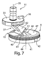
図6では工具31の第1実施形態の側面図が示される。図7は図6の工具31の透視図を示す。工具31は打ち抜き工具として形成され上部工具を成形する打ち抜きスタンプ11および下部工具を成形する打ち抜き鋳型9を含む。打ち抜きスタンプ11は、クランプシャフト34および調節部材またはインデックス部材、あるいは調節楔またはインデックス楔36を有する基体33を備える。クランプシャフト34は打ち抜きスタンプ11を機械側の上部工具受けに固定する役割を果たす。そのとき打ち抜きスタンプ11の配向あるいは打ち抜きスタンプ11の回動位置はインデックス楔36によって決定される。打ち抜きスタンプ11はそのとき回転軸35を中心に回動する。この回転軸35はクランプシャフト34の長手軸および好ましくは基体33の長手軸も成形する。打ち抜きスタンプ11の回動位置の上部工具受けへの受け入れにより、実施形態例では切断工具として示される加工工具37の打ち抜き鋳型9への配向が行われる。打ち抜き鋳型9は、同様に機械側の下部工具受けの中で例えば少なくとも1つのインデックス部材42によって定義された回動位置に固定されることに適合する、基体41を含む。そのとき打ち抜き鋳型9は位置軸48を中心に回動可能である。これは基体41の長手軸あるいは長手方向の中心軸を成形する。打ち抜きスタンプ11と打ち抜き鋳型9の間に、詳細に示されないスクレーパーまたは押さえ器具が設けられうる。
FIG. 6 shows a side view of the first embodiment of the
打ち抜き鋳型9は基体41中に好ましくは周囲を巡る台面47に画定される開口部46を備える。この開口部46は好ましくは完全に基体41に侵入するため、この開口部46を通して打ち抜かれたまたは切り抜かれた工作物部品81は排出され得る。
The punching
打ち抜きスタンプ11にある加工工具37は、それに切断縁部38の自由端が設けられた工具体39を含む。この切断縁部38は周囲を巡るものであり得る。代替的に切断縁部38は打ち抜き面56の領域のみにも形成され得る。工具体39の長手軸40は位置軸35に対して角αで傾斜する。工具体39の長手軸40は位置軸35の外にある。実施形態例では工具体39が縦長の長方体として形成されている。工具体49の自由端には切断縁部38によって画定されるスタンプ面43が設けられる。スタンプ面43は好ましくは直角に工具体39の長手軸40に配向される。縦長の長方形の工具体39の代わりに正方形、円形、楕円形の、または他の輪郭で形作られた工具体39が設けられることも企図され得、そのとき工具体の全ての形の場合に長手軸40が位置軸35に傾斜して配向される。
The
打ち抜き鋳型9は、開口部46の中で好ましくは台面37で画定する内側にある対抗切断縁部51を含む。この内側にある対抗切断縁部51は、台面47に対して突出しスタンプ面43の角度に相応する角度で傾斜する支持面61に設けられる。内側にある対抗切断縁部51に画定する打ち抜き面56は、有利には工具体39の長手軸40に平行に形成されることができ、あるいは支持面61に垂直に立つ。好ましくは、打ち抜き面56は支持面61に対して垂直に例えば1°~2°傾斜するため、打ち抜き面55は支持面61に対して90°より小さい角度で配向される。この打ち抜き面56は切断縁部38から始まり工具体39の外側を成形する壁に相応する。
The punching
この工具31によって、その中にもたらされたフランジ62を有する加工された工作物10にフランジ62の領域で直角の切断縁部を、隆起した残余部分の打ち抜きの際に実現することを可能にする。支持面61は台面47に対して工作物10の工作物面に対するフランジの角度に相応する角度で配向される。打ち抜きスタンプ11における工具体39の長手軸40はまたもやフランジ62への法線として配向される。
The
上部工具11および下部工具9の工具機械1中でのその位置付け軸16、25に沿った独立した制御、並びにストローク軸14、30に沿ったストローク運動の互いから独立した制御によって、傾斜した軸に沿った直線的なストローク運動が制御され得る。任意の曲線状のストローク運動または円弧状のストローク運動も制御され得る。図6および図7の本工具31の場合、例えば打ち抜き鋳型9が作業段階の間静止して工具機械1の中で制御され得、それに対して打ち抜きスタンプ11は傾斜した軸に沿ったストローク運動によって制御される。この傾斜した軸は工具体39の長手軸40に相応する。それによって直角の部分縁部がフランジ62に生成されることができる。
Independent control of the
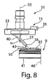
図8では図4の工具31の代替的な実施形態の側面図が示される。図9は図8の工具31の透視図を示す。この実施形態では打ち抜きスタンプ11が図6および図7の実施形態に相応する。
FIG. 8 shows a side view of an alternative embodiment of the
打ち抜き鋳型9は内側にある対抗切断縁部51の実施形態において、図6および図7の実施形態から逸脱する。内側にある対抗切断縁部31は、例えば台面37と同一平面上に位置する。内側にある対抗縁部51に、配向において工具体39の長手軸40に平行な打ち抜き面56が接続される。
The punching
この工具31によってまたも傾斜した打ち抜きストロークが可能である。そのとき傾斜した部分縁部が平らな工作物10に生成される。工具31の傾斜した部分縁部の達成のための制御は図4および図5の上記で説明した工具31の制御に対応して行われる。工具体39の長手軸40の角度位置および対応する打ち抜き面56の配向は工作物10あるいは工作物部品81の前面の角度位置を決定する。
The
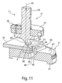
図10では図6の工具31の代替的な実施形態が示される。図11は図10の工具31の透視図を断面図で示す。この工具31ではその工具体39を有する打ち抜きスタンプ11が図6の実施形態に対応する。この実施形態では打ち抜きスタンプ11が2つの部分で形成されることを例示的に企図する。クランプシャフト34および工具体39は、一体的に好ましくはクランプ接続により基体33に固定される。打ち抜き鋳型9は、打ち抜き鋳型9に対抗切断導入部50が設けられるように形成される。この対抗切断導入部50は、例えば交換可能に打ち抜き鋳型9の基体41に設けられうる。この対抗切断導入部50は、打ち抜き鋳型9の基体41中の開口部46に割り当てられた少なくとも1つの内側にある対抗切断縁部51を含む。この対抗切断導入部50は、工作物10に上部工具11との協働により上部にある斜角面64を造形するために形成される。この斜角面64は例えば図11の断面図に示される。
FIG. 10 shows an alternative embodiment of the
対抗切断導入部50は、ここでそれぞれ例えば打ち抜き鋳型の台面47に垂直に配向された内側にある対抗切断縁部51によって画定されたU字型の凹部を有する。対抗切断縁部51の間隔は工具体39あるいは切断縁部38の幅に適合される。それによって斜角面64の定義された長さが作業ストロークにもたらされ得る。対抗切断導入部50は台面67に対して突起した支持面61を有する。この支持面61に工作物10の前面が当接する。
Each of the
例えば工具体39の長手軸40に沿って制御される上部工具11のストローク運動によって、例えば45°の斜角面が導入されることができる。上部工具11の切断縁部38の工作物10への着座および係合の際、これは支持面61に対して対抗切断導入部50で押圧される。それに続いて対抗切断縁部51によって画定されるU字型の開口部に対して、その上に配置された少なくとも1つの切断縁部38を有するスタンプ表面43が沈み込むことによって、材料が剪断される。剪断された材料は開口部46を介して下方に排出される。
For example, a 45 ° bevel can be introduced by the stroke movement of the
工作物10の段階的な側方への移動により、工作物10の前面の比較的大きな領域に渡って斜角面64がもたらされ得る。これは例えば上部工具11および下部工具9のY軸に沿った移動によって行われるか、または工作物10の加工されるべき前面がX軸に沿って配向される限り送り装置22の制御によって行われる。
The gradual lateral movement of the
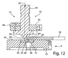
図12では作業位置にある工具31の代替的な実施形態の概略断面図が示される。図13には図12の工具31がさらなる透視断面図に示される。
FIG. 12 shows a schematic cross-sectional view of an alternative embodiment of the
図12および図13のこの工具31は、図10および図11の工具31から工作物10の下面に斜角面64がもたらされることによって逸脱する。上部工具11は図10または図6の工具31の実施形態に相応する。打ち抜き鋳型9は図10の実施形態から逸脱し対抗切断導入部50の代替的実施形態を有する。この対抗切断導入部50は打ち抜き鋳型9の基体41中の開口部46に割り当てられる。この対抗切断導入部50は、同様にその中で上部工具11の工具体39が作業ストローク中に少なくとも部分的に沈み込むことができる通路開口部52を有する。対抗切断導入部50の通路開口部52は工具体39の、特にスタンプ面43および少なくとも1つのそれに設けられた切断縁部38の形状に適合される。対抗切断導入部50の上側は打ち抜き鋳型9の基体41の台面47と同一平面上に配向される。
The
斜角面64を工作物10の下部前面に設けるために、第1ストローク段階の後、下部切断縁部38が通路開口部52の境界に当接し通過することができ、それに対して切断縁部38が工作物10の前面に係合するように、工作物10が通路開口部52に対して位置付けられる。さらなるストローク運動の間、工具体39は通路開口部52に支持され切断縁部38によって斜角面64がもたらされる。対抗切断縁部51に工作物10が支持される。
In order to provide the
工作物10を台面47に押さえつけたままにするために、工作物10の工作物上側の上に、詳細には図示されない対抗鋳型または好ましくは板状に形成された押さえ器具が設けられ得る。
In order to keep the workpiece 10 pressed against the
斜角面64は製作される工作物10の構造的な構成要素でありうる。同様に工作物10のバリ取りが行われ得る。そのことからこの斜角面64の導入あるいは平坦化は溶接縁部の成形のための作業段階の準備にもなりうる。
The
図14では工具31のさらなる代替的実施形態の概略図が示される。この実施形態では加工工具37が印字および/または刻印工具として形成される。工具体39の長手軸40の配向はまたも工作物10のフランジ62に垂直に配向される。上部工具11および下部工具9の独立した制御により、フランジ62の面に標識、印字またはそれらに準じるものが設けられることが可能になる。
FIG. 14 shows a schematic diagram of a further alternative embodiment of the
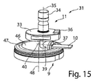
図15は図14の工具31の代替的な実施形態を示す。この実施形態では工具体39の長手軸40が位置軸35に対してより強く傾斜することを企図する。例えばこの傾斜が位置軸35に対して90°を含む。そのような実施形態例では、工作物10または工作物部品81の前面が刻印され、および/または印字され、および/または加工されることが実現する。
FIG. 15 shows an alternative embodiment of the
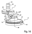
図16では図14の代替的工具31の透視図が示される。この実施形態では加工工具37がエンボス加工工具として形成されることが企図される。工具体39の前面に例えばエンボス部材270が設けられる。これは例えば文字、数字、シンボルまたはそれらに準じるものであり得る。このエンボスを設けるために好ましくは工具体39のスタンプ面43がフランジ62の表面に、あるいは支持面61の傾斜に平行に配向される。
FIG. 16 shows a perspective view of the
図17では図16の工具31の代替的な実施形態が示される。加工工具37は変形工具として形成される。例えば傾斜した工具体39のスタンプ面43に、それによって工作物10のフランジ62に変形輪郭がもたらされ得る変形部材271が設けられる。支持面61の中に輪郭の延び方において変形部材に相応する対抗変形部材272が示される。例えばこの加工工具37によってカップ状の窪みがフランジ62の中に成形される。なぜなら変形部材271が円錐台形の隆起として、および対抗成形要素272がこれと相補的に形成されるためである。代替的に縦溝、V字型溝またはその他の輪郭がフランジ62にもたらされ得る。フランジに変形をもたらす代わりに、フランジ62に開口部または凹部をもたらす打ち抜きスタンプを設けることも企図され得る。この凹部は輪郭において再び多様であり得、様々な形象を含む。フランジ62に例えばエラを設けるために、変形部材271の代わりに打ち抜き曲げ部材も設けられうる。工具体39あるいは個々に傾斜した工具体39のスタンプ面43に配置される加工および/または切断工具の形態は多様であり得る。
FIG. 17 shows an alternative embodiment of the
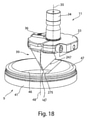
図18では図6の工具31の代替的な実施形態の透視図が示される。この工具31では同様に長手軸40に沿って位置軸48に傾斜した工具体39が設けられる。加工工具37は折りたたみ加工工具として形成される。ここでは工具体39がその前面端に曲げ縁部274を形成するために、婉曲した、または丸められた輪郭、または曲率半径を有するスタンプ面43を備える。
FIG. 18 shows a perspective view of an alternative embodiment of the
下部工具9はまたも開口部46を包囲する台面47を有する基体41を含む。開口部46を画定して対抗曲げ縁部275が下部工具9に形成される。対抗曲げ縁部275は、好ましくは上部工具11の曲げ縁部274と長手に等しい長さか、またはそれよりも長い。対抗曲げ縁部275の輪郭、厚さ、および/または延び方に応じて、フランジ62は工作物10に対してその面から旋回され変形される。実施形態例では対抗曲げ縁部275が円弧状の薄い円盤として形成されている。それによってフランジ62は90°以上の角度で工作物10の工作物面に向かって曲げられ得る。これは以下で図19~22を元に詳細に説明される。
The
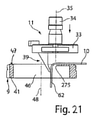
図19では第1作業位置での図18の工具31の概略断面図が示される。下部工具9上で工作物10が台面47に着座する。フランジ62に変形されるべきU字型の切り抜かれた連結金具は下部工具9の開口部46の上にある。第1作業段階では上部工具11がストローク軸14あるいは位置軸35に沿って、曲げ縁部274が工作物10に当接するまで、下部工具9に向かって移動される。そのとき曲げ縁部274は、対抗曲げ縁部275に対して内側に開口部46の方向にずれる。図20に示されるように下部工具9の開口部46の中への上部工具11のさらなるストローク運動によってフランジ62の第1変形が行われる。
FIG. 19 shows a schematic cross-sectional view of the
図21で示されるように下部工具9に対する上部工具11の増加するストローク運動により、フランジ62の90°の変形が行われる。今やさらなる作業段階で、上部工具11が上部位置付け軸16に沿って対抗曲げ縁部275の方向に動くとすぐにフランジ62はさらに曲げられるため、工作物10とフランジ62の間の角度は90°より小さく形成されることができる。
As shown in FIG. 21, the increasing stroke motion of the
工作物10とフランジ62の間の曲げ半径は曲げ縁部274と対抗曲げ縁部275の間の間隔に応じて決まる。間隔が狭いほど曲率半径は小さい。
The bending radius between the workpiece 10 and the
図23では図6の工作物31のさらなる代替的な実施形態が示される。この実施形態では、図6および7に示されるように製作されたフランジ62から始まり工作物10の角にそこで加工工具37が変形工具として形成される、図23の工具31が導入されることが企図される。工具体39はその前端にまたも曲げ縁部274を備える。上部工具11の形態は図18の実施形態に相応しうる。
23 shows a further alternative embodiment of the
下部工具9は台面47に対して高く配置され傾斜して配向される支持面61並びに打ち抜き面56を含む。支持面61と打ち抜き面56の間に対抗曲げ縁部275が設けられる。位置軸35に対して直線的に特に上部工具11の傾斜した長手軸40に沿った傾斜したストローク運動によって、第1フランジ62がもう一度曲げられるためそれに続いて、好ましくはフランジ62とは反対の方向に配向される第2フランジ65が形成される。上部工具11の下部工具9への長手軸40に沿うかまたは打ち抜き面56に平行な直線的なストローク運動の後、上部工具11は持ち上げられることができる。
The
Claims (13)
前記上部工具(11)が、位置軸(35)を共通の中心軸とするクランプシャフト(34)および基体(33)を有し、
前記クランプシャフト(34)に向き合い前記基体(33)に配置された加工工具(37)を含み、
前記下部工具(9)が前記工作物(10)用の台面(47)および前記台面(47)内にある開口部(46)を含む基体(41)を有し、
前記工作物(10)に作用する前記加工工具(37)が前記加工工具(37)を受ける前記上部工具(11)の前記位置軸(35)に対して傾斜する長手軸(40)を有する工具体(39)を備え、
前記加工工具(37)は切断工具であり、前記工具体(39)の一端に少なくとも1つの切断縁部(38)が設けられ、傾斜した打ち抜きストロークによって、前記切断縁部(38)が、前記工作物(10)を切断すると、前記工作物(10)に傾斜した部分縁部が生成されることを特徴とする板状工作物(10)の加工のための工具。 It has an upper tool (11) and a lower tool (9) that are movable relative to each other for machining the workpiece (10) placed between them.
The upper tool (11) has a clamp shaft (34) and a substrate (33) having a position axis (35) as a common central axis .
Includes a machining tool (37) facing the clamp shaft (34) and disposed on the substrate (33).
The lower tool (9) has a substrate (47) for the workpiece (10) and a substrate (41) including an opening (46) in the pedestal (47).
A tool having a longitudinal axis (40) that is tilted with respect to the position axis (35) of the upper tool (11) in which the machining tool (37) acting on the workpiece (10) receives the machining tool (37). Equipped with a body (39)
The machining tool (37) is a cutting tool, and at least one cutting edge portion (38) is provided at one end of the tool body (39), and the cutting edge portion (38) is formed by an inclined punching stroke. A tool for machining a plate-shaped workpiece (10), characterized in that when the workpiece (10) is cut, an inclined partial edge portion is generated on the workpiece (10).
前記上部工具(11)が、位置軸(35)を共通の中心軸とするクランプシャフト(34)および基体(33)を有し、
前記クランプシャフト(34)に向き合い前記基体(33)に配置された加工工具(37)を含み、
前記下部工具(9)が前記工作物(10)用の台面(47)および前記台面(47)内にある開口部(46)を含む基体(41)を有し、
前記工作物(10)に作用する前記加工工具(37)が、前記加工工具(37)を受ける前記上部工具(11)の前記位置軸(35)に対して傾斜する長手軸(40)を有する工具体(39)を備え、
前記加工工具(37)が印字および/または刻印工具であり、
前記加工工具(37)は、エンボス部材(270)を有するエンボス加工工具が設けられる、又は、前記工具体(39)の一端に形成されたスタンプ面(43)および前記スタンプ面(43)に設けられた変形部材(271)を有する変形工具であり、傾斜ストロークによって加工が行われることを特徴とする板状工作物(10)の加工のための工具。 It has an upper tool (11) and a lower tool (9) that are movable relative to each other for machining the workpiece (10) placed between them.
The upper tool (11) has a clamp shaft (34) and a substrate (33) having a position axis (35) as a common central axis.
Includes a machining tool (37) facing the clamp shaft (34) and disposed on the substrate (33).
The lower tool (9) has a substrate (47) for the workpiece (10) and a substrate (41) including an opening (46) in the pedestal (47).
The machining tool (37) acting on the workpiece (10) has a longitudinal axis (40) that is tilted with respect to the position axis (35) of the upper tool (11) that receives the machining tool (37). Equipped with a tool body (39)
The machining tool (37) is a printing and / or engraving tool .
The machining tool (37) is provided with an embossing tool having an embossing member (270) , or is formed on a stamp surface (43) and a stamp surface (43) formed at one end of the tool body (39) . A deforming tool having a provided deforming member (271), which is a tool for machining a plate-shaped workpiece (10), which is characterized in that machining is performed by an inclined stroke .
Applications Claiming Priority (5)
| Application Number | Priority Date | Filing Date | Title |
|---|---|---|---|
| DE102016118175.7A DE102016118175B4 (en) | 2016-09-26 | 2016-09-26 | Machine tool and method for processing plate-shaped workpieces |
| DE102016118175.7 | 2016-09-26 | ||
| DE102016119435.2 | 2016-10-12 | ||
| DE102016119435.2A DE102016119435A1 (en) | 2016-10-12 | 2016-10-12 | Tool and machine tool and method for processing plate-shaped workpieces |
| PCT/EP2017/074299 WO2018055184A1 (en) | 2016-09-26 | 2017-09-26 | Tool and machine tool and method for machining plate-like workpieces |
Publications (3)
| Publication Number | Publication Date |
|---|---|
| JP2019529119A JP2019529119A (en) | 2019-10-17 |
| JP2019529119A5 JP2019529119A5 (en) | 2019-11-28 |
| JP6992055B2 true JP6992055B2 (en) | 2022-01-13 |
Family
ID=60083927
Family Applications (1)
| Application Number | Title | Priority Date | Filing Date |
|---|---|---|---|
| JP2019514020A Active JP6992055B2 (en) | 2016-09-26 | 2017-09-26 | Tools and tool machines and methods for machining plate features |
Country Status (5)
| Country | Link |
|---|---|
| US (1) | US20190217368A1 (en) |
| EP (1) | EP3515625A1 (en) |
| JP (1) | JP6992055B2 (en) |
| CN (1) | CN109789472A (en) |
| WO (1) | WO2018055184A1 (en) |
Families Citing this family (4)
| Publication number | Priority date | Publication date | Assignee | Title |
|---|---|---|---|---|
| US10505925B1 (en) * | 2017-09-06 | 2019-12-10 | Amazon Technologies, Inc. | Multi-layer authentication |
| CN110596932B (en) * | 2019-10-22 | 2022-03-29 | 江苏利通电子股份有限公司 | Display front frame structure and manufacturing process thereof |
| DE102020110718A1 (en) | 2020-04-20 | 2021-10-21 | Trumpf Werkzeugmaschinen Gmbh + Co. Kg | Tool and method for processing plate-shaped workpieces |
| CN113020291A (en) * | 2021-02-02 | 2021-06-25 | 安徽机电职业技术学院 | Steel sheet pile finish rolling cooling arrangement with positioning mechanism |
Citations (3)
| Publication number | Priority date | Publication date | Assignee | Title |
|---|---|---|---|---|
| JP2010506734A (en) | 2006-10-18 | 2010-03-04 | トルンプフ ヴェルクツォイクマシーネン ゲゼルシャフト ミット ベシュレンクテル ハフツング ウント コンパニー コマンディートゲゼルシャフト | Reorientable and rotatable processing tool for cutting and / or forming plate workpieces |
| JP2014515315A (en) | 2011-05-26 | 2014-06-30 | トルンプフ ヴェルクツォイクマシーネン ゲゼルシャフト ミット ベシュレンクテル ハフツング ウント コンパニー コマンディートゲゼルシャフト | Machine tools in the form of presses for machining workpieces, especially metal sheets |
| JP2014161882A (en) | 2013-02-25 | 2014-09-08 | Oiles Ind Co Ltd | Cam mechanism and processing device |
Family Cites Families (14)
| Publication number | Priority date | Publication date | Assignee | Title |
|---|---|---|---|---|
| JPS61123428A (en) * | 1984-11-20 | 1986-06-11 | Matsushita Electric Ind Co Ltd | Metal die device |
| JPH04418U (en) * | 1990-04-12 | 1992-01-06 | ||
| JPH07204753A (en) * | 1993-12-27 | 1995-08-08 | Otto Borries Kg | Device for stamping conical or pseud conical surface of rotating symmetric body |
| JP3415315B2 (en) * | 1995-02-03 | 2003-06-09 | トヨタ自動車株式会社 | Press equipment |
| JPH08332523A (en) * | 1995-06-09 | 1996-12-17 | Toyota Motor Corp | Press method and its device |
| JPH10305319A (en) * | 1997-05-12 | 1998-11-17 | Amutetsuku:Kk | Folding angle measuring method and device therefor in folding machine, folding method using the angle measuring method and the folding machine using the folding method, and an accuracy check block for the angle measurement |
| DE20020499U1 (en) | 2000-12-02 | 2001-03-15 | Trumpf Gmbh & Co | Tool for slitting plate-like workpieces |
| JP4279532B2 (en) * | 2002-10-01 | 2009-06-17 | 株式会社アマダ | Mold apparatus and lower mold for use in processing method of molded product |
| JP2007136463A (en) * | 2005-11-15 | 2007-06-07 | Komatsu Sanki Kk | Die for press brake and method for manufacturing it |
| JP5371177B2 (en) * | 2006-03-24 | 2013-12-18 | 株式会社アマダ | Bending die in punch press and processing method using the bending die |
| EP2177289B1 (en) | 2008-10-20 | 2011-07-06 | TRUMPF Werkzeugmaschinen GmbH + Co. KG | Machine tools and method for discharging a workpiece part |
| IT1397907B1 (en) * | 2010-01-28 | 2013-02-04 | Rolleri S P A | DEVICE FOR LOCKING TOOLS ON BENDING PRESSES |
| CN203076456U (en) * | 2013-03-11 | 2013-07-24 | 浙江金凯德工贸有限公司 | Quick forming device for door edge of anti-theft door |
| CN104588486B (en) * | 2015-02-06 | 2016-08-17 | 安徽江淮汽车股份有限公司 | Sliding punch mechanism and diel |
-
2017
- 2017-09-26 JP JP2019514020A patent/JP6992055B2/en active Active
- 2017-09-26 WO PCT/EP2017/074299 patent/WO2018055184A1/en active Application Filing
- 2017-09-26 CN CN201780058768.6A patent/CN109789472A/en active Pending
- 2017-09-26 EP EP17784194.7A patent/EP3515625A1/en not_active Withdrawn
-
2019
- 2019-03-21 US US16/360,657 patent/US20190217368A1/en not_active Abandoned
Patent Citations (3)
| Publication number | Priority date | Publication date | Assignee | Title |
|---|---|---|---|---|
| JP2010506734A (en) | 2006-10-18 | 2010-03-04 | トルンプフ ヴェルクツォイクマシーネン ゲゼルシャフト ミット ベシュレンクテル ハフツング ウント コンパニー コマンディートゲゼルシャフト | Reorientable and rotatable processing tool for cutting and / or forming plate workpieces |
| JP2014515315A (en) | 2011-05-26 | 2014-06-30 | トルンプフ ヴェルクツォイクマシーネン ゲゼルシャフト ミット ベシュレンクテル ハフツング ウント コンパニー コマンディートゲゼルシャフト | Machine tools in the form of presses for machining workpieces, especially metal sheets |
| JP2014161882A (en) | 2013-02-25 | 2014-09-08 | Oiles Ind Co Ltd | Cam mechanism and processing device |
Also Published As
| Publication number | Publication date |
|---|---|
| JP2019529119A (en) | 2019-10-17 |
| US20190217368A1 (en) | 2019-07-18 |
| CN109789472A (en) | 2019-05-21 |
| WO2018055184A1 (en) | 2018-03-29 |
| EP3515625A1 (en) | 2019-07-31 |
Similar Documents
| Publication | Publication Date | Title |
|---|---|---|
| JP6992055B2 (en) | Tools and tool machines and methods for machining plate features | |
| JP7010931B2 (en) | Tool machines and methods for machining plate features | |
| US11376647B2 (en) | Tools, machines, and methods for machining planar workpieces | |
| KR102100023B1 (en) | Machine for separating and processing plate-shaped workpieces | |
| US11325176B2 (en) | Multiple stroke slotting of planar workpieces | |
| JP7036804B2 (en) | Tools and tool machines and methods for machining plate features | |
| CN109789465B (en) | Tool and machine tool for machining plate-shaped workpieces and method | |
| RU169367U1 (en) | Laser processing plant for processing materials | |
| JP7051825B2 (en) | Tools and tool machines and methods for cutting and / or deforming plate features | |
| WO2010137467A1 (en) | Method and apparatus for incremental forming | |
| JP6772371B2 (en) | Methods and tool machines for machining plate-like workpieces, especially sheet metal | |
| JP7023937B2 (en) | Tool machines and methods for machining plate features | |
| JP2016112593A (en) | Nozzle replacement method in laser punch complex machine and laser punch complex machine as well as laser beam machine | |
| JP2611089B2 (en) | Mold for molding | |
| JP2005131655A (en) | Method and device for bending metal plate | |
| US20220143665A1 (en) | Tool and method for processing plate-shaped workpieces | |
| CN111070951A (en) | Shaft part processor | |
| JP2010058137A (en) | Punch press | |
| JPH09206836A (en) | Through bending apparatus of small article parts | |
| KR100559973B1 (en) | The clamp equipment of being processed goods on table of a saw blade's automatic processing instrument | |
| CN109865868A (en) | The improvement of multicutter platform NC turret punch machine | |
| JP2005342765A (en) | Plate bending die | |
| JP2006167851A (en) | Plate material machine tool | |
| JPH0563736U (en) | Plate processing equipment | |
| JP2001198636A (en) | Method and apparatus for work cutting in turret punch press |
Legal Events
| Date | Code | Title | Description |
|---|---|---|---|
| A521 | Written amendment |
Free format text: JAPANESE INTERMEDIATE CODE: A523 Effective date: 20190820 |
|
| A521 | Written amendment |
Free format text: JAPANESE INTERMEDIATE CODE: A523 Effective date: 20190919 |
|
| A621 | Written request for application examination |
Free format text: JAPANESE INTERMEDIATE CODE: A621 Effective date: 20190925 |
|
| A521 | Written amendment |
Free format text: JAPANESE INTERMEDIATE CODE: A523 Effective date: 20191225 |
|
| A977 | Report on retrieval |
Free format text: JAPANESE INTERMEDIATE CODE: A971007 Effective date: 20201013 |
|
| A131 | Notification of reasons for refusal |
Free format text: JAPANESE INTERMEDIATE CODE: A131 Effective date: 20201020 |
|
| A601 | Written request for extension of time |
Free format text: JAPANESE INTERMEDIATE CODE: A601 Effective date: 20210115 |
|
| A601 | Written request for extension of time |
Free format text: JAPANESE INTERMEDIATE CODE: A601 Effective date: 20210322 |
|
| A521 | Written amendment |
Free format text: JAPANESE INTERMEDIATE CODE: A523 Effective date: 20210416 |
|
| TRDD | Decision of grant or rejection written | ||
| A01 | Written decision to grant a patent or to grant a registration (utility model) |
Free format text: JAPANESE INTERMEDIATE CODE: A01 Effective date: 20211109 |
|
| A61 | First payment of annual fees (during grant procedure) |
Free format text: JAPANESE INTERMEDIATE CODE: A61 Effective date: 20211208 |
|
| R150 | Certificate of patent or registration of utility model |
Ref document number: 6992055 Country of ref document: JP Free format text: JAPANESE INTERMEDIATE CODE: R150 |