JP6908698B2 - Mounting order determination device, mounting order inspection device, mounting order determination method, and mounting order inspection method - Google Patents
Mounting order determination device, mounting order inspection device, mounting order determination method, and mounting order inspection method Download PDFInfo
- Publication number
- JP6908698B2 JP6908698B2 JP2019519841A JP2019519841A JP6908698B2 JP 6908698 B2 JP6908698 B2 JP 6908698B2 JP 2019519841 A JP2019519841 A JP 2019519841A JP 2019519841 A JP2019519841 A JP 2019519841A JP 6908698 B2 JP6908698 B2 JP 6908698B2
- Authority
- JP
- Japan
- Prior art keywords
- mounting
- component
- order
- electronic components
- mounting order
- Prior art date
- Legal status (The legal status is an assumption and is not a legal conclusion. Google has not performed a legal analysis and makes no representation as to the accuracy of the status listed.)
- Active
Links
Images


Classifications
-
- H—ELECTRICITY
- H05—ELECTRIC TECHNIQUES NOT OTHERWISE PROVIDED FOR
- H05K—PRINTED CIRCUITS; CASINGS OR CONSTRUCTIONAL DETAILS OF ELECTRIC APPARATUS; MANUFACTURE OF ASSEMBLAGES OF ELECTRICAL COMPONENTS
- H05K13/00—Apparatus or processes specially adapted for manufacturing or adjusting assemblages of electric components
- H05K13/08—Monitoring manufacture of assemblages
- H05K13/0882—Control systems for mounting machines or assembly lines, e.g. centralized control, remote links, programming of apparatus and processes as such
-
- H—ELECTRICITY
- H05—ELECTRIC TECHNIQUES NOT OTHERWISE PROVIDED FOR
- H05K—PRINTED CIRCUITS; CASINGS OR CONSTRUCTIONAL DETAILS OF ELECTRIC APPARATUS; MANUFACTURE OF ASSEMBLAGES OF ELECTRICAL COMPONENTS
- H05K13/00—Apparatus or processes specially adapted for manufacturing or adjusting assemblages of electric components
- H05K13/08—Monitoring manufacture of assemblages
- H05K13/081—Integration of optical monitoring devices in assembly lines; Processes using optical monitoring devices specially adapted for controlling devices or machines in assembly lines
- H05K13/0818—Setup of monitoring devices prior to starting mounting operations; Teaching of monitoring devices for specific products; Compensation of drifts during operation, e.g. due to temperature shifts
-
- G—PHYSICS
- G05—CONTROLLING; REGULATING
- G05B—CONTROL OR REGULATING SYSTEMS IN GENERAL; FUNCTIONAL ELEMENTS OF SUCH SYSTEMS; MONITORING OR TESTING ARRANGEMENTS FOR SUCH SYSTEMS OR ELEMENTS
- G05B19/00—Programme-control systems
- G05B19/02—Programme-control systems electric
- G05B19/418—Total factory control, i.e. centrally controlling a plurality of machines, e.g. direct or distributed numerical control [DNC], flexible manufacturing systems [FMS], integrated manufacturing systems [IMS], computer integrated manufacturing [CIM]
- G05B19/41865—Total factory control, i.e. centrally controlling a plurality of machines, e.g. direct or distributed numerical control [DNC], flexible manufacturing systems [FMS], integrated manufacturing systems [IMS], computer integrated manufacturing [CIM] characterised by job scheduling, process planning, material flow
-
- H—ELECTRICITY
- H05—ELECTRIC TECHNIQUES NOT OTHERWISE PROVIDED FOR
- H05K—PRINTED CIRCUITS; CASINGS OR CONSTRUCTIONAL DETAILS OF ELECTRIC APPARATUS; MANUFACTURE OF ASSEMBLAGES OF ELECTRICAL COMPONENTS
- H05K13/00—Apparatus or processes specially adapted for manufacturing or adjusting assemblages of electric components
- H05K13/04—Mounting of components, e.g. of leadless components
-
- G—PHYSICS
- G05—CONTROLLING; REGULATING
- G05B—CONTROL OR REGULATING SYSTEMS IN GENERAL; FUNCTIONAL ELEMENTS OF SUCH SYSTEMS; MONITORING OR TESTING ARRANGEMENTS FOR SUCH SYSTEMS OR ELEMENTS
- G05B2219/00—Program-control systems
- G05B2219/30—Nc systems
- G05B2219/36—Nc in input of data, input key till input tape
- G05B2219/36195—Assembly, mount of electronic parts onto board
-
- H—ELECTRICITY
- H05—ELECTRIC TECHNIQUES NOT OTHERWISE PROVIDED FOR
- H05K—PRINTED CIRCUITS; CASINGS OR CONSTRUCTIONAL DETAILS OF ELECTRIC APPARATUS; MANUFACTURE OF ASSEMBLAGES OF ELECTRICAL COMPONENTS
- H05K13/00—Apparatus or processes specially adapted for manufacturing or adjusting assemblages of electric components
- H05K13/04—Mounting of components, e.g. of leadless components
- H05K13/0404—Pick-and-place heads or apparatus, e.g. with jaws
- H05K13/0408—Incorporating a pick-up tool
- H05K13/0409—Sucking devices
-
- H—ELECTRICITY
- H05—ELECTRIC TECHNIQUES NOT OTHERWISE PROVIDED FOR
- H05K—PRINTED CIRCUITS; CASINGS OR CONSTRUCTIONAL DETAILS OF ELECTRIC APPARATUS; MANUFACTURE OF ASSEMBLAGES OF ELECTRICAL COMPONENTS
- H05K13/00—Apparatus or processes specially adapted for manufacturing or adjusting assemblages of electric components
- H05K13/04—Mounting of components, e.g. of leadless components
- H05K13/0404—Pick-and-place heads or apparatus, e.g. with jaws
- H05K13/0408—Incorporating a pick-up tool
- H05K13/041—Incorporating a pick-up tool having multiple pick-up tools
-
- H—ELECTRICITY
- H05—ELECTRIC TECHNIQUES NOT OTHERWISE PROVIDED FOR
- H05K—PRINTED CIRCUITS; CASINGS OR CONSTRUCTIONAL DETAILS OF ELECTRIC APPARATUS; MANUFACTURE OF ASSEMBLAGES OF ELECTRICAL COMPONENTS
- H05K13/00—Apparatus or processes specially adapted for manufacturing or adjusting assemblages of electric components
- H05K13/08—Monitoring manufacture of assemblages
- H05K13/081—Integration of optical monitoring devices in assembly lines; Processes using optical monitoring devices specially adapted for controlling devices or machines in assembly lines
- H05K13/0812—Integration of optical monitoring devices in assembly lines; Processes using optical monitoring devices specially adapted for controlling devices or machines in assembly lines the monitoring devices being integrated in the mounting machine, e.g. for monitoring components, leads, component placement
Description
本明細書は、電子部品(以下、部品と称する)を基板に装着する部品装着機や部品装着ラインに関し、より詳細には、複数の部品の装着順序の決定や検査に関する。 The present specification relates to a component mounting machine and a component mounting line for mounting electronic components (hereinafter referred to as components) on a substrate, and more particularly to determining and inspecting a mounting order of a plurality of components.
プリント配線が施された基板に部品を実装するための諸作業(以下、対基板作業と称する)を実施して、回路基板を量産する技術が普及している。対基板作業を実施する対基板作業機として、はんだ印刷機、部品装着機、リフロー機、基板検査機などがある。これらの対基板作業機を連結して対基板作業ラインを構成することが一般的になっている。さらに、複数の部品装着機を列設して部品装着ラインを構成する場合も多い。部品装着機は、一般的に、基板搬送装置、部品供給装置、および部品移載装置を備える。 A technique for mass-producing circuit boards by carrying out various operations (hereinafter referred to as substrate-to-board operations) for mounting components on a printed circuit board has become widespread. As a board-to-board work machine that performs board-to-board work, there are a solder printing machine, a component mounting machine, a reflow machine, a board inspection machine, and the like. It has become common to connect these board-to-board work machines to form a board-to-board work line. Further, in many cases, a plurality of component mounting machines are arranged in a row to form a component mounting line. The component mounting machine generally includes a board transfer device, a component supply device, and a component transfer device.
部品装着機が装着作業を実施する基板の中には、複数の部品を上下に重ねて装着する多重装着の構造を有する基板がある。多重装着が有る基板を生産するときに、部品装着機は、先ず多重装着の下側の部品を装着し、後で上側の部品を装着する。つまり、多重装着される複数の部品は、装着順序の先後が制約される。この種の多重装着に関する技術例が特許文献1、2に開示されている。
Among the boards on which the component mounting machine performs mounting work, there is a board having a multiple mounting structure in which a plurality of components are mounted one on top of the other. When producing a board with multiple mounting, the component mounting machine first mounts the lower component of the multiple mounting, and then mounts the upper component. That is, a plurality of parts to be mounted multiple times are restricted in the mounting order.
特許文献1の部品装着機は、記憶手段、相対位置変更手段、および制御手段を備える。記憶手段は、装着順序ごとに部品が装着される基板上の水平位置情報、既に装着されている部品の高さ位置の情報および部品厚さの情報を記憶する。相対位置変更手段は、取出ノズルと基板の相対位置を変更させる。制御手段は、記憶された三つの情報に基づき、相対位置変更手段の水平方向および高さ方向の相対位置を制御する。これによれば、装着する高さ位置が一定でないときにも、確実に部品装着を行える、とされている。換言すると、多重装着の下側の部品の高さ位置に誤差が生じても、上側の部品を装着できる、とされている。
The component mounting machine of
また、特許文献2は、基板上に部品を段積みして装着する(多重装着を行う)部品装着機を開示している。この部品装着機は、部品の装着位置をXY座標値で表すとともに段積みする部品の複数の装着基準高さをZ座標値で表す三次元座標データの記憶部と、部品を段積みする移載手段と、三次元座標データに基づいて移載手段の動作を制御する制御手段と、を備える。これによれば、三次元座標データを用い、基板上に電子部品を段積みして装着できる、とされている。
Further,
ところで、特許文献1、2では、複数の部品の既知の装着順序に基づいて、多重装着が実施される、ここで、基板種ごとの部品配置を表すCADデータは、一般的には二次元データとされている。したがって、CADデータに基づいて、多重装着される複数の部品を判定することはできるが、複数の部品の上下関係、換言すると装着順序を判定することはできない。このため、従来技術では、多重装着される複数の部品について、オペレータが基板種ごとに個別に装着順序を設定しており、手間がかかっていた。
By the way, in
また、基板の小形化への要求に対応して、近年では部品の高密度実装が進んでいる。高密度実装では、複数の部品の装着位置が相互に近接して、装着順序が制約される場合が発生する。この場合、仮に高さ寸法が大きい大形部品を先に装着すると、高さ寸法が小さい小形部品を後から近接して装着する際に、装着済みの大形部品が干渉して装着作業に支障をきたす。近接装着される複数の部品についても、従来技術では、オペレータが基板種ごとに個別に装着順序を設定しており、手間がかかっていた。 Further, in recent years, high-density mounting of components has been progressing in response to the demand for miniaturization of substrates. In high-density mounting, the mounting positions of a plurality of components may be close to each other and the mounting order may be restricted. In this case, if the large parts with a large height dimension are mounted first, the large parts that have already been mounted interfere with each other when the small parts with a small height dimension are mounted in close proximity to each other, which hinders the mounting work. To cause. In the prior art, the operator sets the mounting order individually for each board type even for a plurality of components to be mounted close to each other, which is troublesome.
さらに、多重装着や近接装着に該当する複数の部品の装着順序は、装着作業の詳細を規定するジョブデータに予め設定される。ここで、基板の部分的な設計変更や部品のモデルチェンジ、生産上の不具合などに起因して、ジョブデータの一部が修正される場合がある。このとき、修正されたジョブデータで、装着順序が不適当になるおそれが生じる。したがって、予め設定された装着順序が正しいか否かを検査する必要がある。 Further, the mounting order of the plurality of parts corresponding to the multiple mounting and the proximity mounting is preset in the job data that defines the details of the mounting work. Here, a part of the job data may be corrected due to a partial design change of the board, a model change of a part, a production defect, or the like. At this time, there is a possibility that the mounting order may become inappropriate in the corrected job data. Therefore, it is necessary to inspect whether or not the preset mounting order is correct.
本明細書では、多重装着および近接装着の少なくとも一方に該当する複数の部品について、基板種ごとに個別に装着順序を設定する手間を軽減した装着順序決定装置、および装着順序決定方法を提供することを解決すべき課題とする。さらには、多重装着および近接装着の少なくとも一方に該当する複数の部品に予め設定された装着順序が正しいか否かを自動で検査する装着順序検査装置、および装着順序検査方法を提供することを課題とする。 The present specification provides a mounting order determining device and a mounting order determining method that reduce the trouble of individually setting the mounting order for each substrate type for a plurality of parts corresponding to at least one of multiple mounting and proximity mounting. Is an issue to be solved. Furthermore, it is an object of the present invention to provide a mounting order inspection device for automatically inspecting whether or not a preset mounting order is correct for a plurality of parts corresponding to at least one of multiple mounting and proximity mounting, and a mounting order inspection method. And.
本明細書は、部品装着機を用いて、または、複数の前記部品装着機を列設して構成した部品装着ラインを用いて、複数の電子部品を基板のそれぞれの装着位置に装着する装着作業に先んじて、複数の前記電子部品の装着順序を決定する装着順序決定装置であって、上下に重ねて装着される多重装着の可能性がある複数の前記電子部品の部品種を含む多重装着部品種群を対象として、前記装着順序の優先度を順位付けした階層情報を、各前記部品種が多重装着の上側になるか下側になるかについての使用実績を参照して各前記部品種に自動設定する階層設定部と、複数の前記電子部品の寸法および前記装着位置に基づいて、前記多重装着に該当する複数の前記電子部品の組合せを抽出する該当部品抽出部と、前記組合せに含まれる前記電子部品の前記部品種に設定された前記階層情報に基づいて、前記組合せの中で前記電子部品の前記装着順序を決定する順序決定部と、を備える装着順序決定装置を開示する。 In the present specification, a mounting operation of mounting a plurality of electronic components at their respective mounting positions on a substrate by using a component mounting machine or by using a component mounting line configured by arranging a plurality of the component mounting machines in a row. A mounting order determining device that determines the mounting order of a plurality of the electronic components prior to The hierarchical information in which the priority of the mounting order is prioritized for the product type group is applied to each of the component types by referring to the usage record of whether each of the component types is on the upper side or the lower side of the multiple mounting. a layer setting unit for automatically setting, on the basis of the size and the attachment positions of the plurality of the electronic components, and the corresponding component extraction unit for extracting a plurality of said combinations of electronic components corresponding to the multiple instrumentation attachment, the combination Disclosed is a mounting order determining device including an order determining unit for determining the mounting order of the electronic component in the combination based on the hierarchical information set for the component type of the electronic component included.
また、本明細書は、部品装着機を用いて、または、複数の前記部品装着機を列設して構成した部品装着ラインを用いて、複数の電子部品を基板のそれぞれの装着位置に装着する装着作業に先んじて、複数の前記電子部品に予め設定された装着順序を検査する装着順序検査装置であって、上下に重ねて装着される多重装着の可能性がある複数の前記電子部品の部品種を含む多重装着部品種群を対象として、前記装着順序の優先度を順位付けした階層情報を、各前記部品種が多重装着の上側になるか下側になるかについての使用実績を参照して各前記部品種に自動設定する階層設定部と、複数の前記電子部品の寸法および前記装着位置に基づいて、前記多重装着に該当する複数の前記電子部品の組合せを抽出する該当部品抽出部と、前記組合せに含まれる前記電子部品の前記部品種に設定された前記階層情報に基づいて、前記組合せの中で前記電子部品の正しい装着順序を決定する順序決定部と、設定された前記装着順序と正しい前記装着順序を比較して検査する順序検査部と、を備える装着順序検査装置を開示する。 Further, in the present specification, a plurality of electronic components are mounted at their respective mounting positions on a substrate by using a component mounting machine or by using a component mounting line composed of a plurality of the component mounting machines arranged in a row. A mounting order inspection device that inspects a preset mounting order for a plurality of the electronic components prior to the mounting work, and is a portion of the plurality of the electronic components that may be mounted one above the other. For the multi-mounting component type group including the product type, refer to the hierarchical information in which the priority of the mounting order is ranked, and refer to the usage record of whether each of the component types is on the upper side or the lower side of the multi-mounting. a layer setting unit for automatically setting to each of said portions varieties Te, based on the dimensions and the mounting positions of the plurality of the electronic components, appropriate component extraction for extracting a plurality of said combinations of electronic components corresponding to the multiple instrumentation deposition Based on the unit, the hierarchical information set for the component type of the electronic component included in the combination, and the order determining unit for determining the correct mounting order of the electronic component in the combination, the set unit. Disclosed is a mounting order inspection device including an order inspection unit that compares and inspects the mounting order and the correct mounting order.
さらに、本明細書は、部品装着機を用いて、または、複数の前記部品装着機を列設して構成した部品装着ラインを用いて、複数の電子部品を基板のそれぞれの装着位置に装着する装着作業に先んじて、複数の前記電子部品の装着順序を決定する装着順序決定方法であって、上下に重ねて装着される多重装着の可能性がある複数の前記電子部品の部品種を含む多重装着部品種群を対象として、前記装着順序の優先度を順位付けした階層情報を、各前記部品種が多重装着の上側になるか下側になるかについての使用実績を参照して各前記部品種に自動設定し、複数の前記電子部品の寸法および前記装着位置に基づいて、前記多重装着に該当する複数の前記電子部品の組合せを抽出し、前記組合せに含まれる前記電子部品の前記部品種に設定された前記階層情報に基づいて、前記組合せの中で前記電子部品の前記装着順序を決定する、装着順序決定方法を開示する。 Further, in the present specification, a plurality of electronic components are mounted at their respective mounting positions on a substrate by using a component mounting machine or by using a component mounting line composed of a plurality of the component mounting machines arranged in a row. A mounting order determination method for determining the mounting order of a plurality of the electronic components prior to the mounting work, which includes multiple mounting of the electronic components that may be mounted one above the other. For the mounted component type group, the hierarchical information in which the priority of the mounted order is ranked is referred to the usage record of whether each of the component types is on the upper side or the lower side of the multiple mounting. automatically set the varieties, based on the dimensions and the mounting positions of the plurality of the electronic component, wherein extracting a plurality of said combinations of electronic components corresponding to the multiple instrumentation attachment, the said electronic component included in the combination Disclosed is a mounting order determination method for determining the mounting order of the electronic components in the combination based on the hierarchical information set for the component type.
さらに、本明細書は、部品装着機を用いて、または、複数の前記部品装着機を列設して構成した部品装着ラインを用いて、複数の電子部品を基板のそれぞれの装着位置に装着する装着作業に先んじて、複数の前記電子部品に予め設定された装着順序を検査する装着順序検査方法であって、上下に重ねて装着される多重装着の可能性がある複数の前記電子部品の部品種を含む多重装着部品種群を対象として、前記装着順序の優先度を順位付けした階層情報を、各前記部品種が多重装着の上側になるか下側になるかについての使用実績を参照して各前記部品種に自動設定し、複数の前記電子部品の寸法および前記装着位置に基づいて、前記多重装着に該当する複数の前記電子部品の組合せを抽出し、前記組合せに含まれる前記電子部品の前記部品種に設定された前記階層情報に基づいて、前記組合せの中で前記電子部品の正しい装着順序を決定し、設定された前記装着順序と正しい前記装着順序を比較して検査する、装着順序検査方法を開示する。 Further, in the present specification, a plurality of electronic components are mounted at their respective mounting positions on a substrate by using a component mounting machine or by using a component mounting line composed of a plurality of the component mounting machines arranged in a row. This is a mounting order inspection method for inspecting a preset mounting order for a plurality of the electronic components prior to the mounting work, and is a portion of the plurality of electronic components that may be mounted one above the other. For the multi-mounting component type group including the product type, refer to the hierarchical information in which the priority of the mounting order is ranked, and refer to the usage record of whether each of the component types is on the upper side or the lower side of the multi-mounting. automatically set to each of said portions varieties Te, wherein based on the dimensions and the mounting positions of the plurality of the electronic component, extracting a plurality of said combinations of electronic components corresponding to the multiple instrumentation attachment, included in the combination Based on the hierarchical information set for the component type of the electronic component, the correct mounting order of the electronic component is determined in the combination, and the set mounting order and the correct mounting order are compared and inspected. , Disclose the mounting order inspection method.
本明細書で開示する装着順序決定装置や装着順序決定方法によれば、多重装着の可能性がある部品種群を対象として、装着順序の優先度を順位付けした階層情報が各部品種に予め設定される。そして、多重装着に該当する電子部品の組合せの中で、階層情報に基づいて正しい装着順序が自動的に決定される。したがって、従来オペレータが基板種ごとに個別に装着順序を設定していた手間が軽減される。 According to the mounting order determining unit and mounting sequence determining method disclosed herein, as targeting components species group are likely to be multiple instrumentation attachment, ranked hierarchy information priority of the mounting order in advance to the respective parts varieties Set. Then, among the combinations of the electronic components corresponding to the multiple instrumentation attachment, the correct mounting order is determined automatically based on the hierarchical information. Therefore, the time and effort required for the operator to individually set the mounting order for each board type is reduced.
また、本明細書で開示する装着順序検査装置や装着順序検査方法によれば、複数の電子部品に予め設定された装着順序を検査するときに、多重装着の可能性がある部品種群を対象として、装着順序の優先度を順位付けした階層情報が各部品種に予め設定される。そして、多重装着に該当する電子部品の組合せの中で、階層情報に基づいて正しい装着順序が自動的に決定される。したがって、正しい装着順序と比較して、設定された装着順序が正しいか否かが自動で検査される。 Further, according to the placement sequencing inspection device and placement sequencing test methods disclosed herein, when examining the placement order set in advance to a plurality of electronic components, the component type group are likely to be multiple instrumentation deposition As a target, hierarchical information in which the priority of the mounting order is prioritized is set in advance for each component type. Then, among the combinations of the electronic components corresponding to the multiple instrumentation attachment, the correct mounting order is determined automatically based on the hierarchical information. Therefore, it is automatically inspected whether or not the set mounting order is correct as compared with the correct mounting order.
1.部品装着機1の構成
まず、第1実施形態の装着順序決定装置7の対象となる部品装着機1について、例示説明する。図1は、第1実施形態の装着順序決定装置7の対象となる部品装着機1の主要部の斜視図である。図1の左上から右下に向かう方向が基板Kを搬送するX軸方向であり、右上から左下に向かう方向が部品装着機1の前後方向となるY軸方向である。部品装着機1は、基板搬送装置2、部品供給装置3、部品移載装置4、部品カメラ5、制御部6(図2参照)、および機台10などで構成されている。なお、装着順序決定装置7の対象は、複数の部品装着機1を列設して構成した部品装着ラインであってもよい。1. 1. Configuration of the
基板搬送装置2は、第1ガイドレール21および第2ガイドレール22、一対のコンベアベルト、ならびにクランプ装置などで構成される。第1ガイドレール21および第2ガイドレール22は、機台10の上部中央を横断してX軸方向に延在し、かつ互いに平行するように機台10に組み付けられる。第1ガイドレール21および第2ガイドレール22の直下に、互いに平行に配置された一対のコンベアベルトが並設される。一対のコンベアベルトは、コンベア搬送面に基板Kを戴置した状態で輪転して、基板Kを機台10の中央部に設定された装着実施位置に搬入および搬出する。また、機台10の中央部のコンベアベルトの下方にクランプ装置が設けられる。クランプ装置は、基板Kを複数の押し上げピンで押し上げて水平姿勢でクランプし、装着実施位置に位置決めする。
The
部品供給装置3は、部品装着機1の前側に着脱可能に装備される。部品供給装置3は、デバイスパレット39および複数のフィーダ装置31などで構成される。デバイスパレット39は、薄い矩形箱状の部材である。デバイスパレット39の上面には、平行してY軸方向に延びる複数のスロットが刻設されている。複数のフィーダ装置31は、それぞれスロットに着脱可能に挿入されて取り付けられる。
The parts supply
フィーダ装置31は、本体32と、本体32の前側に設けられた供給リール33と、本体32の後端上部に設けられた部品取り出し部34とを備える。供給リール33には、多数の部品が所定ピッチで封入されたキャリアテープが巻回保持される。このキャリアテープが所定ピッチで送り出されると、部品は、封入状態を解除されて部品取り出し部34に順次送り込まれる。部品供給装置3は、フィーダ装置31の一部に代えて、図略のトレイ式装置の取り付けが可能となっている。トレイ式装置は、複数の部品を保持するトレイを用いて、比較的大形の部品を供給する。
The
部品移載装置4は、一対のY軸レール41、Y軸移動台42、Y軸モータ43、X軸移動台44、X軸モータ45、装着ヘッド46、ロータリツール47、およびZ軸モータ48などで構成される。一対のY軸レール41は、機台10の後部から前部の部品供給装置3の上方にかけて配設される。Y軸移動台42は、一対のY軸レール41に装荷されている。Y軸移動台42は、Y軸モータ43からボールねじ機構を介して駆動され、Y軸方向に移動する。X軸移動台44は、Y軸移動台42に装荷されている。X軸移動台44は、X軸モータ45からボールねじ機構を介して駆動され、X軸方向に移動する。
The
装着ヘッド46は、X軸移動台44の前側に配設されている。装着ヘッド46は、ロータリツール47を下側に有する。図1には省略されているが、ロータリツール47の下側に、複数本の吸着ノズルが環状に配置されている。複数本の吸着ノズルは、ロータリツール47の下側で回転されて、1本が選択される。選択された吸着ノズルは、Z軸モータ48に駆動されて昇降する。また、吸着ノズルは、負圧の供給によって部品を吸着し、正圧の供給によって部品を基板Kに装着する。これに限定されず装着ヘッド46は、部品を挟持する挟持式装着具を有してもよい。
The mounting
部品移載装置4は、吸着装着サイクルを繰り返すことによって、装着作業を進める。吸着装着サイクルについて詳述すると、部品移載装置4の装着ヘッド46は、部品供給装置3に移動して複数本の吸着ノズルでそれぞれ部品を吸着する。次に、装着ヘッド46が部品カメラ5に移動すると、複数の部品の吸着状態が撮像される。その次に、装着ヘッド46は、基板Kに移動して複数の部品を装着し、再び部品供給装置3に戻る。
The
部品カメラ5は、基板搬送装置2と部品供給装置3との間の機台10の上面に、上向きに設けられている。部品カメラ5は、装着ヘッド46の複数本の吸着ノズルが部品取り出し部34で部品を吸着して基板Kに移動する途中の状態を撮影する。これにより、部品カメラ5は、複数本の吸着ノズルにそれぞれ保持された部品を一括して撮像できる。取得された撮像データは画像処理されて、部品の吸着状態が確認される。部品の吸着位置や回転角のずれ、リードの曲がりなどが確認されると、必要に応じて装着動作が微調整される。また、装着が困難な部品は、廃棄される。
The
制御部6は、基板種ごとのジョブデータを保持して、装着作業を制御する。ジョブデータは、装着作業における部品の装着順序などの詳細な手順や方法などを記述したデータである。制御部6は、基板搬送装置2、部品供給装置3、部品移載装置4、および部品カメラ5に各種の指令を送信する。また、制御部6は、これらの装置から動作状況などに関する情報を受信する。
The
2.第1実施形態の装着順序決定装置7
第1実施形態の装着順序決定装置7の説明に移る。装着順序決定装置7は、部品装着機1または部品装着ラインを用いた装着作業に先んじて、複数の部品の装着順序を決定する。図2は、第1実施形態の装着順序決定装置7の機能構成を示すブロック図である。装着順序決定装置7は、コンピュータ装置を用いて構成される。装着順序決定装置7は、部品装着機1の制御部6に接続される。2. Mounting
The description of the mounting
また、装着順序決定装置7は、基板種ごとのCADデータを記憶したCADデータベース79に接続される。CADデータは、基板K上における部品の配置を表す装着位置の情報を含んでいる。CADデータは、各部品の寸法や電気特性値などの情報を蓄積した図略の部品データベースにリンクされている。装着順序決定装置7は、CADデータに基づいて、前述したジョブデータを作成する。装着順序決定装置7は、ジョブデータを作成する際に機能する3つの機能部、すなわち、階層設定部71、該当部品抽出部72、および順序決定部73を含む。
Further, the mounting
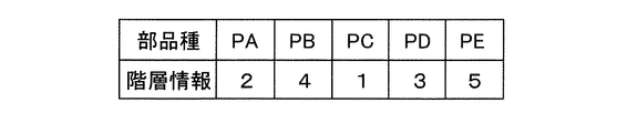
図3は、第1実施形態の装着順序決定装置7の動作フローを示すフロー図である。図3のステップS1で、階層設定部71は、多重装着部品種群を対象として、装着順序の優先度を順位付けした階層情報を各部品種に設定する。多重装着部品種群は、上下に重ねて装着される多重装着の可能性がある複数の部品の部品種を含む。多重装着部品種群として、CPU部品PA、小形チップ部品PB、チップ部品PC、メモリ部品PD、およびシールド部品PEからなる部品種群を例示する。
FIG. 3 is a flow chart showing an operation flow of the mounting
図4は、CPU部品PAの平面図である。CPU部品PAは、平面視で正方形の部品である。CPU部品PAは、基板に接続される56個のボールグリッドB1を底面の周辺部分に有する。CPU部品PAは、さらに、必要に応じてメモリ部品PDを接続できる9個のボールグリッドB2を上面の中央部分に有する。つまり、CPU部品PAは、単独で使用される場合と、上面にメモリ部品PDが装着されて使用される場合とがある。 FIG. 4 is a plan view of the CPU component PA. The CPU component PA is a square component in a plan view. The CPU component PA has 56 ball grids B1 connected to the substrate in a peripheral portion of the bottom surface. The CPU component PA further has nine ball grids B2 in the central portion of the upper surface to which the memory component PD can be connected, if necessary. That is, the CPU component PA may be used alone or may be used with the memory component PD mounted on the upper surface.
図5は、小形チップ部品PBの平面図である。小形チップ部品PBは、平面視で小さな長方形の部品である。小形チップ部品PBは、2個の接続部JBを底面の短辺寄りに有する。図6は、チップ部品PCの平面図である。チップ部品PCは、小形チップ部品PBの概ね2倍の長さ、幅、および高さをもつ長方形状の部品である。チップ部品PCは、2個の接続部JCを底面の短辺寄りに有する。 FIG. 5 is a plan view of the small chip component PB. The small chip component PB is a small rectangular component in a plan view. The small chip component PB has two connecting portions JB near the short side of the bottom surface. FIG. 6 is a plan view of the chip component PC. The chip component PC is a rectangular component having approximately twice the length, width, and height of the small chip component PB. The chip component PC has two connecting portions JC near the short side of the bottom surface.
図7は、メモリ部品PDの平面図である。メモリ部品PDは、一辺の長さがCPU部品PAの半分弱の正方形の部品である。メモリ部品PDは、CPU部品PAに接続される9個のボールグリッドBDを底面に有する。メモリ部品PDは、さらに、必要に応じて3個の小形チップ部品PBを接続できる3対の接続部JDを上面に有する。図8は、シールド部品PEを示す図である。シールド部品PEは、一辺の長さがメモリ部品PDの2倍程度の正方形の箱状の部品であり、下方に開口している。シールド部品PEは、鉄などの電磁シールド材料を用いて形成されており、電界および磁界の少なくとも一方を遮蔽する。 FIG. 7 is a plan view of the memory component PD. The memory component PD is a square component having a side length of less than half that of the CPU component PA. The memory component PD has nine ball grid BDs connected to the CPU component PA on the bottom surface. The memory component PD further has three pairs of connecting portions JD on the upper surface to which three small chip components PB can be connected as needed. FIG. 8 is a diagram showing a shield component PE. The shield component PE is a square box-shaped component whose side length is about twice that of the memory component PD, and is open downward. The shield component PE is formed by using an electromagnetic shield material such as iron, and shields at least one of an electric field and a magnetic field.
階層設定部71は、前述した五つの部品種を対象として、多重装着の下側に装着される可能性が大きい部品種に、小さな階層情報を設定する。さらに、階層設定部71は、多重装着の上側に装着される可能性が大きい部品種に、大きな階層情報を設定する。階層設定部71は、各部品種の使用実績を参照して階層情報を自動設定してもよい。あるいは、階層設定部71は、オペレータがマニュアル設定した階層情報を記憶してもよい。各部品種が多重装着の上側になるか下側になるかは、仮に使用実績が無くとも、基板Kの回路構成や部品種の構造および機能などに基づいて判断可能である。
The
図9は、五つの部品種に設定された階層情報を例示する一覧表の図である。図9の例で、CPU部品PAに第2階層が設定され、小形チップ部品PBに第4階層が設定される。また、チップ部品PCに第1階層が設定され、メモリ部品PDに第3階層が設定され、シールド部品PEに第5階層が設定される。実際には、さらに多数の部品種に対して、多数の階層情報が設定されてもよい。階層情報は、必ずしも連続した値である必要は無い。また、複数の部品種に対して同一値の階層情報が設定されてもよい。 FIG. 9 is a diagram of a list illustrating hierarchical information set for the five component types. In the example of FIG. 9, the second layer is set in the CPU component PA, and the fourth layer is set in the small chip component PB. Further, the first layer is set in the chip component PC, the third layer is set in the memory component PD, and the fifth layer is set in the shield component PE. In practice, a large number of hierarchical information may be set for a larger number of component types. Hierarchical information does not necessarily have to be continuous values. Further, hierarchical information having the same value may be set for a plurality of component types.
生産する基板Kの基板種が逐次追加されても、部品種ごとに設定された階層情報は、原則的に変更されない。ただし、新たに追加された基板種における装着順序を参照して、設定された階層情報を修正することも可能である。 Even if the substrate types of the substrate K to be produced are sequentially added, the hierarchical information set for each component type is not changed in principle. However, it is also possible to modify the set hierarchical information by referring to the mounting order in the newly added board type.
図3のステップS2に戻り、該当部品抽出部72は、多重装着が有る基板種に着目して、そのCADデータをCADデータベース79から取得する。換言すると、該当部品抽出部72は、着目する基板種に装着される部品の装着位置の情報をCADデータベース79から取得する。さらに、該当部品抽出部72は、装着される部品の寸法の情報を部品データベースから取得する。
Returning to step S2 of FIG. 3, the corresponding
次のステップS3で、該当部品抽出部72は、部品の装着位置、および部品の寸法に基づいて、多重装着に該当する複数の部品の組合せを抽出する。詳述すると、該当部品抽出部72は、部品の中央が位置する装着位置に部品の縦寸法および横寸法を考慮して、基板K上における部品の存在範囲を求めることができる。該当部品抽出部72は、複数の部品の存在範囲の少なくとも一部が相互に重なる場合に多重装着と判定して、当該の複数の部品の組合せを抽出する。なお、二重装着に限定されず、三重装着以上の多重装着も存在する。
In the next step S3, the corresponding
次のステップS4で、順序決定部73は、抽出された組合せに含まれる部品の部品種に設定された階層情報に基づいて、組合せの中で部品の装着順序を決定する。順序決定部73が決定する装着順序は、組合せの中での先後関係を限定するものであり、連続して装着することを意味しない。
In the next step S4, the
例えば、図10は、A基板種の基板KAの多重装着状態を示す平面図である。図11は、図10の多重装着状態を側方から見た側面図である。図示される多重装着の実際の装着順序は、先ず、基板KAの上面にCPU部品PAが装着される。次に、CPU部品PAの上面にメモリ部品PDが装着される。 For example, FIG. 10 is a plan view showing a multiple mounting state of the substrate KA of the A substrate type. FIG. 11 is a side view of the multiple mounting state of FIG. 10 as viewed from the side. In the actual mounting order of the multiple mounting shown in the figure, first, the CPU component PA is mounted on the upper surface of the substrate KA. Next, the memory component PD is mounted on the upper surface of the CPU component PA.
該当部品抽出部72は、多重装着に該当するCPU部品PAとメモリ部品PDの組合せを抽出する。順序決定部73は、CPU部品PAに設定された第2階層、およびメモリ部品PDに設定された第3階層に基づいて、階層情報が小さい順番に装着順序を決定する。すなわち、順序決定部73は、CPU部品PAの装着作業が先で、メモリ部品PDの装着作業が後であると決定する。決定した装着順序は、実際の装着順序に一致する。なお、CPU部品PAとメモリ部品PDの先後関係が逆にならなければ、間に他の部品の装着作業が実施されてもよい。
The corresponding
また例えば、図12は、B基板種の基板KBの多重装着状態を示す平面図である。図13は、図12の多重装着状態をZ方向から見た側面断面図である。図示される多重装着の実際の装着順序は、先ず、基板KBの上面に6個のチップ部品PCおよびメモリ部品PDが装着される。次に、メモリ部品PDの上面に3個の小形チップ部品PBが装着される。最後に、6個のチップ部品PC、メモリ部品PD、および3個の小形チップ部品PBを覆うように、シールド部品PEが基板KBに装着される。 Further, for example, FIG. 12 is a plan view showing a multiple mounting state of the substrate KB of the B substrate type. FIG. 13 is a side sectional view of the multiple mounting state of FIG. 12 as viewed from the Z direction. In the actual mounting order shown in the multiple mounting, first, six chip component PCs and a memory component PD are mounted on the upper surface of the substrate KB. Next, three small chip components PB are mounted on the upper surface of the memory component PD. Finally, the shield component PE is mounted on the substrate KB so as to cover the six chip component PCs, the memory component PD, and the three small chip components PB.
該当部品抽出部72は、多重装着に該当する3個の小形チップ部品PB、6個のチップ部品PC、メモリ部品PD、およびシールド部品PEの組合せを抽出する。順序決定部73は、部品種の階層情報が小さい順番に装着順序を決定する。すなわち、順序決定部73は、先ずチップ部品PC(第1階層)、2番目にメモリ部品PD(第3階層)、3番目に小形チップ部品PB(第4階層)、4番目にシールド部品PE(第5階層)という装着順序を決定する。決定した装着順序は、実際の装着順序に一致する。なお、チップ部品PCおよびメモリ部品PDだけに注目すれば、多重装着となっていないので、装着順序の先後の入れ替わりが許容される。また、これらの部品種の装着順序の間に、他の部品の装着作業が実施されてもよい。
The corresponding
図3のステップS5に戻り、装着順序決定装置7は、基板Kに装着する全部の部品を対象として最適化処理を実施し、ジョブデータを完成させる。このとき、順序決定部73によって決定された多重装着部位の装着順序は、最適化処理の必要条件として扱われる。次のステップS6で、装着順序決定装置7は、多重装着が有る全部の基板種に対する最適化処理が終了しているか否か判定する。未終了のとき、装着順序決定装置7は、着目する基板種を変更して、動作フローの実行をステップS2に戻す。
Returning to step S5 of FIG. 3, the mounting
多重装着が有る全部の基板種について、ステップS2からステップS6までのループが繰り返される。なお、多重装着も近接装着(詳細後述)も無い基板種に対して、装着順序決定装置7は、ステップS6の最適化処理のみを実施する。全部の基板種に対する最適化処理が終了すると、装着順序決定装置7は動作フローを終了する。この後、装着順序決定装置7は、次に生産する基板種のジョブデータを制御部6に送信する。これにより、部品装着機1は、装着作業を実施する準備が整う。なお、装着順序決定装置7は、生産する基板種が決定するごとに、ステップS2からステップS6までを実施してもよい。
The loop from step S2 to step S6 is repeated for all the substrate types having multiple mounting. The mounting
第1実施形態の装着順序決定装置7は、ステップS1で、多重装着の可能性がある部品種群を対象として、装着順序の優先度を順位付けした階層情報を各部品種に予め設定しておく。さらに、装着順序決定装置7は、多重装着が有る各基板種に対して、それぞれステップS2からステップS4を実行する。これにより、多重装着に該当する部品の組合せの中で、階層情報に基づいて正しい装着順序が自動的に決定される。したがって、従来オペレータが基板種ごとに個別に装着順序を設定していた手間が軽減される。
In step S1, the mounting
3.第2実施形態の装着順序検査装置7A
次に、第2実施形態の装着順序検査装置7Aについて、図14を参考にして、第1実施形態の装着順序決定装置7と異なる点を主に説明する。装着順序検査装置7Aは、部品装着機1または部品装着ラインを用いた装着作業に先んじて、複数の部品に予め設定された装着順序を検査する。図14は、第2実施形態の装着順序検査装置7Aの機能構成を示すブロック図である。3. 3. Mounting
Next, the mounting
装着順序検査装置7Aは、CADデータベース79に加えて、ジョブデータベース78にも接続される。ジョブデータベース78は、基板Kの基板種ごとに作成されたジョブデータを記憶している。装着順序検査装置7Aは、ジョブデータベース78から基板種ごとのジョブデータを取得する。これらのジョブデータには、多重装着される複数の部品の装着順序が予め設定されている。ジョブデータは、変更可能とされており、変更によって装着順序が不適正になるおそれを内包している。したがって、部品装着機1で装着作業を開始する以前に、予め設定された装着順序が正しいか否かを検査する必要がある。
The mounting
装着順序検査装置7Aは、階層設定部71、該当部品抽出部72、順序決定部73に加えて、順序検査部74を含む。階層設定部71、該当部品抽出部72、および順序決定部73は、第1実施形態と同様に動作する。ただし、順序決定部73は、多重装着される複数の部品の正しい装着順序を決定することができる。順序検査部74は、ジョブデータに予め設定された装着順序と、順序決定部73が決定した正しい装着順序を比較して検査する。したがって、設定された装着順序が正しいか否かが自動で検査される。
The mounting
4.第3実施形態の装着順序決定装置7B
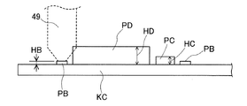
次に、第3実施形態の装着順序決定装置7Bについて、図15〜図17を参考にして、第1および第2実施形態と異なる点を主に説明する。第3実施形態の装着順序決定装置7Bは、近接装着部品種群を対象とする。図15は、近接装着部品種群を模式的に説明するC基板種の基板KCの側面図である。図15の例で、小形チップ部品PB、チップ部品PC、およびメモリ部品PDは、近接装着部品種群を構成する。4. Mounting
Next, the mounting
詳述すると、部品の高密度実装が進むと、複数の部品の装着位置が相互に近接して、装着順序が制約される。仮に、近接装着部品種群の中で高さ寸法HDが大きいメモリ部品PDを先に装着した場合を想定する。この場合、高さ寸法HBが小さい小形チップ部品PBを後から装着する際に、小形チップ部品PBを吸着した吸着ノズル49と、メモリ部品PDとが干渉する。
More specifically, as the high-density mounting of components progresses, the mounting positions of a plurality of components are close to each other, and the mounting order is restricted. It is assumed that the memory component PD having a large height dimension HD in the proximity mounting component group is mounted first. In this case, when the small chip component PB having a small height dimension HB is mounted later, the
同様に、高さ寸法HCが中間のチップ部品PCを吸着した吸着ノズル49と、装着済みのメモリ部品PDとが干渉するおそれもある。さらに、小形チップ部品PBを吸着した吸着ノズル49と、装着済みのチップ部品PCとが干渉するおそれもある。第3実施形態の装着順序決定装置7Bは、これらの干渉を確実に回避する。
Similarly, there is a possibility that the
図16は、第3実施形態の装着順序決定装置7Bの機能構成を示すブロック図である。装着順序決定装置7Bの階層設定部71B、該当部品抽出部72B、および順序決定部73Bは、第1実施形態と異なる機能を発揮する。詳述すると、階層設定部71Bは、近接装着の可能性がある複数の部品について、高さ寸法HBが小さい小形チップ部品PBに小さな階層情報を設定する。さらに、階層設定部71Bは、高さ寸法HCが中間のチップ部品PC中間の階層情報を設定し、高さ寸法HDが大きいメモリ部品PDに大きな階層情報を設定する。図17は、三つの部品種に設定された階層情報を例示する一覧表の図である。
FIG. 16 is a block diagram showing a functional configuration of the mounting
図17の例で、小形チップ部品PBに第11階層が設定され、チップ部品PCに第12階層が設定され、メモリ部品PDに第13階層が設定されている。図17と図9を比較すればわかるように、第1実施形態と第3実施形態とで階層情報の順番が異なっている。すなわち、第1実施形態では、チップ部品PC、メモリ部品PD、小形チップ部品PBの順番であるのに対し、第3実施形態では、小形チップ部品PB、チップ部品PC、メモリ部品PDの順番となっている。 In the example of FIG. 17, the eleventh layer is set in the small chip component PB, the twelfth layer is set in the chip component PC, and the thirteenth layer is set in the memory component PD. As can be seen by comparing FIGS. 17 and 9, the order of the hierarchical information is different between the first embodiment and the third embodiment. That is, in the first embodiment, the order is the chip component PC, the memory component PD, and the small chip component PB, whereas in the third embodiment, the order is the small chip component PB, the chip component PC, and the memory component PD. ing.
該当部品抽出部72Bは、近接装着に該当する複数の部品の組合せを抽出する。順序決定部73Bは、組合せに含まれる部品の部品種に設定された階層情報が小さい順番に装着順序を決定する。つまり、該当部品抽出部72Bは、先ず小形チップ部品PB、2番目にチップ部品PC、3番目にメモリ部品PDという順序を決定する。これにより、近接装着部品種群の中で、高さ寸法(HB、HC、HD)が小さい順番に装着作業が実施されるので、前述した干渉が発生しない。
The corresponding
5.第4実施形態の装着順序決定装置7C
次に、第4実施形態の装着順序決定装置7Cについて、図9、図17、図18を参考にして、第1〜第3実施形態と異なる点を主に説明する。第4実施形態において、部品装着機1は、A基板種の基板KA、B基板種の基板KB、およびC基板種の基板KCを切り替えて生産する。基板種の切り替え時には、適宜段取り替え作業が行われる。A基板種およびB基板種は、多重装着が有る第一群の基板種に含まれる。また、C基板種は、近接装着が有る第二群の基板種に含まれる。第4実施形態の装着順序決定装置7Cは、第一群および第二群の基板種に対して、階層情報を使い分ける。5. Mounting
Next, the mounting
図18は、第4実施形態の装着順序決定装置7Cの機能構成を示すブロック図である。装着順序決定装置7Cの階層設定部71C、該当部品抽出部72C、および順序決定部73Cは、第1および第3実施形態と異なる機能を発揮する。詳述すると、階層設定部71Cは、第一群の基板種に適用する第一階層情報を設定し、さらに、第二群の基板種に適用する第二階層情報を設定する。第一階層情報は、図9に示された五つの部品種の階層情報に一致する。第二階層情報は、図17に示された三つの部品種の階層情報に一致する。第一階層情報および第二階層情報は、階層情報の順番が互いに異なる。
FIG. 18 is a block diagram showing a functional configuration of the mounting
該当部品抽出部72Cは、第一群の基板種について、多重装着に該当する複数の部品の組合せを抽出する。さらに、該当部品抽出部72Cは、第二群の基板種について、近接装着に該当する複数の部品の組合せを抽出する。順序決定部73Cは、装着対象となる基板Kの基板種の別に応じて、第一階層情報および第二階層情報を使い分ける。詳細には、順序決定部73Cは、第一群の基板種であるA基板種およびB基板種のジョブデータを作成する際に、第一階層情報を使用する。また、順序決定部73Cは、第二群の基板種であるC基板種のジョブデータを作成する際に、第二階層情報を使用する。
The corresponding
これによれば、基板種に依存して装着順序の先後が入れ替わる部品の組合せが存在しても、基板種の群の別に応じて、第一階層情報および第二階層情報が使い分けられる。したがって、装着順序決定装置7Cは、全部の基板種について正しい装着順序を決定できる。
According to this, even if there is a combination of parts in which the mounting order is changed depending on the board type, the first layer information and the second layer information are used properly according to the group of the board types. Therefore, the mounting
6.第5実施形態の装着順序決定装置7D
次に、第5実施形態の装着順序決定装置7Dについて、図19を参考にして、第1〜第4実施形態と異なる点を主に説明する。図19は、第5実施形態の装着順序決定装置7Dの機能構成を示すブロック図である。第5実施形態において、装着順序決定装置7Dは、第一部品装着機11の制御部6、および第二部品装着機12の制御部6に接続される。第一部品装着機11および第二部品装着機12は、基板種を分担する。詳細には、第一部品装着機11は、A基板種およびB基板種を含む第一群の基板種を装着作業の対象とする。第二部品装着機12は、C基板種を含む第二群の基板種を装着作業の対象とする。6. Mounting
Next, the mounting
第5実施形態の装着順序決定装置7Dの階層設定部71D、該当部品抽出部72D、および順序決定部73Dは、第1、第3、および第4実施形態と異なる機能を発揮する。詳述すると、階層設定部71Dは、第一部品装着機11に適用する第一階層情報を設定し、さらに、第二部品装着機12に適用する第二階層情報を設定する。第一階層情報は、図9に示された五つの部品種の階層情報に一致する。第二階層情報は、図17に示された三つの部品種の階層情報に一致する。第一階層情報および第二階層情報は、階層情報の順番が互いに異なる。
The layer setting unit 71D, the corresponding
該当部品抽出部72Dは、第一群の基板種について、多重装着に該当する複数の部品の組合せを抽出する。さらに、該当部品抽出部72Dは、第二群の基板種について、近接装着に該当する複数の部品の組合せを抽出する。順序決定部73Dは、装着作業を実施する第一部品装着機11および第二部品装着機12の別に応じて、第一階層情報および第二階層情報を使い分ける。詳細には、順序決定部73Dは、第一部品装着機11で生産するA基板種およびB基板種のジョブデータを作成する際に、第一階層情報を使用する。また、順序決定部73Dは、第二部品装着機12で生産するC基板種のジョブデータを作成する際に、第二階層情報を使用する。
The corresponding
これによれば、基板種に依存して装着順序の先後が入れ替わる部品の組合せが存在しても、基板種を分担する第一部品装着機11および第二部品装着機12の別に応じて、第一階層情報および第二階層情報が使い分けられる。したがって、装着順序決定装置7Dは、全部の基板種について正しい装着順序を決定できる。
According to this, even if there is a combination of parts in which the mounting order is changed depending on the board type, the first
7.実施形態の応用および変形
なお、各実施形態において、多重装着部品種群にも近接装着部品種群にも該当しない部品種に、最も小さな階層情報を設定することができる。最も小さな階層情報は、基板Kに直接的に装着されることを意味する。これにより、部品種群を意識することなく、全部の部品種を一括して扱うことができる。また、第4および第5実施形態において、第一群の基板種に多重装着が有り、第二群の基板種に近接装着が有るとしたが、これに限定されない。つまり、複数の群の全てに多重装着が有る場合や、複数の群の全てに近接装着が有る場合も、対応可能である。また、複数の部品種に同一値の階層情報が設定された態様では、同一値が設定されたどの部品種が先に装着されてもよい。7. Application and Modification of the Embodiment In each embodiment, the smallest hierarchical information can be set for a component type that does not correspond to the multiple mounting component group or the proximity mounting component group. The smallest hierarchical information means that it is mounted directly on the substrate K. As a result, all the part types can be handled at once without being aware of the part type group. Further, in the fourth and fifth embodiments, it is assumed that the substrate type of the first group has multiple mounting and the substrate type of the second group has proximity mounting, but the present invention is not limited to this. That is, it is possible to deal with the case where all of the plurality of groups have multiple mounting, or the case where all of the plurality of groups have proximity mounting. Further, in the embodiment in which the hierarchical information of the same value is set for a plurality of component types, any component type having the same value may be mounted first.
さらに、第3〜第5実施形態の装着順序決定装置(7B、7C、7D)にジョブデータベース78および順序検査部74を付加して、装着順序検査装置とすることができる。また、第1および第3〜第5実施形態の装着順序決定装置(7、7B、7C、7D)は、装着順序決定方法として実施することができる。第2実施形態の装着順序検査装置7Aも、装着順序検査方法として実施することができる。第1〜第5実施形態は、その他にも様々な応用や変形が可能である。
Further, the
1:部品装着機 11:第一部品装着機 12:第二部品装着機 2:基板搬送装置 3:部品供給装置 31:フィーダ装置 4:部品移載装置 5:部品カメラ 6:制御部 7、7B、7C、7D:装着順序決定装置 7A:装着順序検査装置 71、71B、71C、71D:階層設定部 72、72B、72C、72D:該当部品抽出部 73、73B、73C、73D:順序決定部 74:順序検査部 78:ジョブデータベース 79:CADデータベース K、KA、KB、KC:基板 PA:CPU部品 PB:小形チップ部品 PC:チップ部品 PD:メモリ部品 PE:シールド部品 HB、HC、HD:高さ寸法
1: Parts mounting machine 11: First parts mounting machine 12: Second parts mounting machine 2: Board transfer device 3: Parts supply device 31: Feeder device 4: Parts transfer device 5: Parts camera 6:
Claims (8)
上下に重ねて装着される多重装着の可能性がある複数の前記電子部品の部品種を含む多重装着部品種群を対象として、前記装着順序の優先度を順位付けした階層情報を、各前記部品種が多重装着の上側になるか下側になるかについての使用実績を参照して各前記部品種に自動設定する階層設定部と、
複数の前記電子部品の寸法および前記装着位置に基づいて、前記多重装着に該当する複数の前記電子部品の組合せを抽出する該当部品抽出部と、
前記組合せに含まれる前記電子部品の前記部品種に設定された前記階層情報に基づいて、前記組合せの中で前記電子部品の前記装着順序を決定する順序決定部と、
を備える装着順序決定装置。 Prior to the mounting work of mounting a plurality of electronic components at the respective mounting positions of the board by using a component mounting machine or by using a component mounting line configured by arranging a plurality of the component mounting machines in a row, a plurality of electronic components are mounted. A mounting order determining device for determining the mounting order of the electronic components of the above.
Each of the above-mentioned parts provides hierarchical information in which the priority of the mounting order is prioritized for a group of multiple mounting component types including a plurality of the component types of the electronic components that may be mounted on top of each other. A hierarchy setting unit that automatically sets each part type by referring to the usage record of whether the product type is on the upper side or the lower side of multiple mounting.
Based on the size and the attachment positions of the plurality of the electronic components, and the corresponding component extraction unit for extracting a plurality of said combinations of electronic components corresponding to the multiple instrumentation deposition,
An order determining unit that determines the mounting order of the electronic components in the combination based on the hierarchical information set for the component type of the electronic components included in the combination.
A mounting order determination device.
前記該当部品抽出部は、前記多重装着に該当する複数の前記電子部品の前記組合せを抽出し、
前記順序決定部は、前記組合せに含まれる前記電子部品の前記部品種に設定された前記階層情報が小さい順番に前記装着順序を決定する、
請求項1または2に記載の装着順序決定装置。 The layer setting unit sets small layer information for the component type that is likely to be mounted on the lower side of the multiple mounting, and further, the component type that is likely to be mounted on the upper side of the multiple mounting. Set the large hierarchical information in
The corresponding component extraction unit extracts the combination of the plurality of the electronic components corresponding to the multiple mounting, and obtains the combination.
The order determining unit determines the mounting order in ascending order of the hierarchical information set in the component type of the electronic component included in the combination.
The mounting order determining device according to claim 1 or 2.
前記基板の第一群の基板種に適用する前記階層情報である第一階層情報を設定し、さらに、
前記第一群以外の第二群の基板種に適用する前記階層情報であって、前記第一階層情報とは異なる前記階層情報である第二階層情報を設定し、
前記順序決定部は、装着対象となる前記基板の前記基板種に応じて、前記第一階層情報および前記第二階層情報を使い分ける、
請求項1〜3のいずれか一項に記載の装着順序決定装置。 The hierarchy setting unit
The first layer information, which is the layer information applied to the substrate type of the first group of the substrates, is set, and further, the first layer information is set.
The second layer information, which is the layer information applied to the substrate types of the second group other than the first group and is different from the first layer information, is set.
The order determining unit uses the first layer information and the second layer information properly according to the substrate type of the substrate to be mounted.
The mounting order determining device according to any one of claims 1 to 3.
前記基板の第一群の基板種を前記装着作業の対象とする第一部品装着機、または第一部品装着ラインに適用する前記階層情報である第一階層情報を設定し、さらに、
前記第一群以外の第二群の基板種を前記装着作業の対象とする第二部品装着機、または第二部品装着ラインに適用する前記階層情報であって、前記第一階層情報とは異なる前記階層情報である第二階層情報を設定し、
前記順序決定部は、前記装着作業を実施する前記部品装着機または前記部品装着ラインに応じて、前記第一階層情報および前記第二階層情報を使い分ける、
請求項1〜3のいずれか一項に記載の装着順序決定装置。 The hierarchy setting unit
The first layer information, which is the layer information for applying the substrate type of the first group of the boards to the first component mounting machine to be the target of the mounting work or the first component mounting line, is set, and further.
The hierarchical information that applies the substrate types of the second group other than the first group to the second component mounting machine or the second component mounting line that is the target of the mounting work, and is different from the first layer information. Set the second layer information, which is the layer information,
The order determining unit properly uses the first layer information and the second layer information according to the component mounting machine or the component mounting line on which the mounting work is performed.
The mounting order determining device according to any one of claims 1 to 3.
上下に重ねて装着される多重装着の可能性がある複数の前記電子部品の部品種を含む多重装着部品種群を対象として、前記装着順序の優先度を順位付けした階層情報を、各前記部品種が多重装着の上側になるか下側になるかについての使用実績を参照して各前記部品種に自動設定する階層設定部と、
複数の前記電子部品の寸法および前記装着位置に基づいて、前記多重装着に該当する複数の前記電子部品の組合せを抽出する該当部品抽出部と、
前記組合せに含まれる前記電子部品の前記部品種に設定された前記階層情報に基づいて、前記組合せの中で前記電子部品の正しい前記装着順序を決定する順序決定部と、
設定された前記装着順序と正しい前記装着順序を比較して検査する順序検査部と、
を備える装着順序検査装置。 Prior to the mounting work of mounting a plurality of electronic components at the respective mounting positions of the board by using a component mounting machine or by using a component mounting line configured by arranging a plurality of the component mounting machines in a row, a plurality of electronic components are mounted. It is a mounting order inspection device that inspects the mounting order preset for the electronic component of the above.
Each of the above-mentioned parts provides hierarchical information in which the priority of the mounting order is prioritized for a group of multiple mounting component types including a plurality of the component types of the electronic components that may be mounted on top of each other. A hierarchy setting unit that automatically sets each part type by referring to the usage record of whether the product type is on the upper side or the lower side of multiple mounting.
Based on the size and the attachment positions of the plurality of the electronic components, and the corresponding component extraction unit for extracting a plurality of said combinations of electronic components corresponding to the multiple instrumentation deposition,
An order determining unit that determines the correct mounting order of the electronic components in the combination based on the hierarchical information set for the component type of the electronic components included in the combination.
An order inspection unit that compares and inspects the set mounting order and the correct mounting order,
A mounting sequence inspection device.
上下に重ねて装着される多重装着の可能性がある複数の前記電子部品の部品種を含む多重装着部品種群を対象として、前記装着順序の優先度を順位付けした階層情報を、各前記部品種が多重装着の上側になるか下側になるかについての使用実績を参照して各前記部品種に自動設定し、
複数の前記電子部品の寸法および前記装着位置に基づいて、前記多重装着に該当する複数の前記電子部品の組合せを抽出し、
前記組合せに含まれる前記電子部品の前記部品種に設定された前記階層情報に基づいて、前記組合せの中で前記電子部品の前記装着順序を決定する、
装着順序決定方法。 Prior to the mounting work of mounting a plurality of electronic components at the respective mounting positions of the board by using a component mounting machine or by using a component mounting line configured by arranging a plurality of the component mounting machines in a row, a plurality of electronic components are mounted. It is a mounting order determination method for determining the mounting order of the electronic components of the above.
Each of the above-mentioned parts provides hierarchical information in which the priority of the mounting order is prioritized for a group of multiple mounting component types including a plurality of the component types of the electronic components that may be mounted on top of each other. Automatically set for each of the above component types by referring to the usage record of whether the product type is on the upper side or the lower side of multiple mounting.
Based on the size and the attachment positions of the plurality of the electronic component, extracting a plurality of said combinations of electronic components corresponding to the multiple instrumentation deposition,
Based on the hierarchical information set for the component type of the electronic component included in the combination, the mounting order of the electronic component is determined in the combination.
How to determine the mounting order.
上下に重ねて装着される多重装着の可能性がある複数の前記電子部品の部品種を含む多重装着部品種群を対象として、前記装着順序の優先度を順位付けした階層情報を、各前記部品種が多重装着の上側になるか下側になるかについての使用実績を参照して各前記部品種に自動設定し、
複数の前記電子部品の寸法および前記装着位置に基づいて、前記多重装着に該当する複数の前記電子部品の組合せを抽出し、
前記組合せに含まれる前記電子部品の前記部品種に設定された前記階層情報に基づいて、前記組合せの中で前記電子部品の正しい前記装着順序を決定し、
設定された前記装着順序と正しい前記装着順序を比較して検査する、
装着順序検査方法。 Prior to the mounting work of mounting a plurality of electronic components at the respective mounting positions of the board by using a component mounting machine or by using a component mounting line configured by arranging a plurality of the component mounting machines in a row, a plurality of electronic components are mounted. A mounting order inspection method for inspecting a preset mounting order for the electronic component of the above.
Each of the above-mentioned parts provides hierarchical information in which the priority of the mounting order is prioritized for a group of multiple mounting component types including a plurality of the component types of the electronic components that may be mounted on top of each other. Automatically set for each of the above component types by referring to the usage record of whether the product type is on the upper side or the lower side of multiple mounting.
Based on the size and the attachment positions of the plurality of the electronic component, extracting a plurality of said combinations of electronic components corresponding to the multiple instrumentation deposition,
Based on the hierarchical information set for the component type of the electronic component included in the combination, the correct mounting order of the electronic component in the combination is determined.
Inspect by comparing the set mounting order with the correct mounting order.
Installation order inspection method.
Applications Claiming Priority (1)
| Application Number | Priority Date | Filing Date | Title |
|---|---|---|---|
| PCT/JP2017/019194 WO2018216101A1 (en) | 2017-05-23 | 2017-05-23 | Mounting order determination device, mounting order examination device, mounting order determination method, and mounting order examination method |
Publications (2)
| Publication Number | Publication Date |
|---|---|
| JPWO2018216101A1 JPWO2018216101A1 (en) | 2020-02-27 |
| JP6908698B2 true JP6908698B2 (en) | 2021-07-28 |
Family
ID=64396342
Family Applications (1)
| Application Number | Title | Priority Date | Filing Date |
|---|---|---|---|
| JP2019519841A Active JP6908698B2 (en) | 2017-05-23 | 2017-05-23 | Mounting order determination device, mounting order inspection device, mounting order determination method, and mounting order inspection method |
Country Status (5)
| Country | Link |
|---|---|
| US (1) | US11363751B2 (en) |
| EP (1) | EP3634098B1 (en) |
| JP (1) | JP6908698B2 (en) |
| CN (1) | CN110622631B (en) |
| WO (1) | WO2018216101A1 (en) |
Cited By (1)
| Publication number | Priority date | Publication date | Assignee | Title |
|---|---|---|---|---|
| JP7422282B2 (en) | 2020-03-27 | 2024-01-26 | パナソニックIpマネジメント株式会社 | Production control device, production data creation method, and production data creation program |
Families Citing this family (4)
| Publication number | Priority date | Publication date | Assignee | Title |
|---|---|---|---|---|
| KR102230598B1 (en) * | 2019-06-05 | 2021-03-22 | 한화정밀기계 주식회사 | Component mounting apparatus |
| US20230111622A1 (en) * | 2020-03-06 | 2023-04-13 | Fuji Corporation | Image data generation device and component mounting system |
| CN111405842B (en) * | 2020-05-15 | 2020-10-30 | 大连日佳电子有限公司 | Pin self-adaptive positioning plug-in mounting method and system for three-pin electronic component |
| US11631018B2 (en) | 2020-06-01 | 2023-04-18 | Bank Of America Corporation | Performing enhanced exception processing using cognitive automation tools |
Family Cites Families (27)
| Publication number | Priority date | Publication date | Assignee | Title |
|---|---|---|---|---|
| KR19980069992A (en) * | 1997-01-20 | 1998-10-26 | 사와무라시코우 | Method for mounting a compound unit of an optical semiconductor device and a support substrate and an optical semiconductor device on a support substrate |
| JPH11306208A (en) * | 1998-04-16 | 1999-11-05 | Fujitsu Ltd | Floor plan method and device and computer readable recording medium recording floor plan program |
| JP2001077597A (en) * | 1999-09-02 | 2001-03-23 | Matsushita Electric Ind Co Ltd | Method for mounting electronic component |
| CN100508726C (en) * | 2000-08-04 | 2009-07-01 | 松下电器产业株式会社 | Method for optimization of an order of components mounting, apparatus using the same, and assembly machine |
| JP4115683B2 (en) * | 2001-06-21 | 2008-07-09 | 松下電器産業株式会社 | Electronic component mounting apparatus and electronic component mounting method |
| JP2003031997A (en) * | 2001-07-16 | 2003-01-31 | Matsushita Electric Ind Co Ltd | Component-mounting method, component-mounting machine using the same, component-mounting object, mounting order deciding program, mounting machine operation program and recording medium recording them |
| JP3589658B2 (en) * | 2001-09-28 | 2004-11-17 | 松下電器産業株式会社 | Optimization device, mounting device and electronic component mounting system |
| JP2004087874A (en) * | 2002-08-28 | 2004-03-18 | Fuji Mach Mfg Co Ltd | Electronic circuit component mounting method, mounting program and mounting system |
| WO2004066702A1 (en) * | 2003-01-23 | 2004-08-05 | Matsushita Electric Industrial Co., Ltd. | Method for optimization of an order of component mounting, apparatus using the same, and mounter |
| US8019455B2 (en) * | 2004-05-17 | 2011-09-13 | Panasonic Corporation | Component mounting order deciding method and component mounting order deciding apparatus |
| JP2006013448A (en) * | 2004-05-21 | 2006-01-12 | Matsushita Electric Ind Co Ltd | Line balance control method, line balance controller, and component mounting unit |
| EP1827073A1 (en) * | 2004-12-15 | 2007-08-29 | Matsushita Electric Industrial Co., Ltd. | Action time shortening method, action time shortening device, program, and parts mounting machine |
| JP4548310B2 (en) | 2005-11-07 | 2010-09-22 | パナソニック株式会社 | Electronic component mounting method |
| CN101379896B (en) * | 2006-02-09 | 2011-11-23 | 松下电器产业株式会社 | Method for determining pickup order of component |
| JP3848967B2 (en) | 2006-04-10 | 2006-11-22 | 株式会社日立ハイテクインスツルメンツ | Electronic component automatic mounting device |
| JP5574690B2 (en) * | 2009-12-14 | 2014-08-20 | Juki株式会社 | Component mounting apparatus and component mounting method |
| KR101192727B1 (en) * | 2010-01-29 | 2012-10-18 | 야마하하쓰도키 가부시키가이샤 | Component mounting system |
| JP5675013B2 (en) * | 2010-06-10 | 2015-02-25 | 富士機械製造株式会社 | Electronic circuit assembly method and electronic circuit assembly system |
| JP5789680B2 (en) * | 2012-01-17 | 2015-10-07 | パイオニア株式会社 | Electronic component mounting apparatus and electronic component mounting method |
| JP5848994B2 (en) * | 2012-03-07 | 2016-01-27 | ヤマハ発動機株式会社 | Mounting data creation method for component mounting device |
| JP6075910B2 (en) * | 2012-07-25 | 2017-02-08 | Juki株式会社 | Information management system and information providing method |
| JP6076046B2 (en) * | 2012-11-07 | 2017-02-08 | ヤマハ発動機株式会社 | Electronic component mounting apparatus, arithmetic device and mounting method |
| WO2014141422A1 (en) * | 2013-03-14 | 2014-09-18 | 富士機械製造株式会社 | Production management system for component mounting device |
| JP6209607B2 (en) * | 2013-06-24 | 2017-10-04 | 富士機械製造株式会社 | Component mounting system and component mounting method |
| JP6043873B2 (en) * | 2013-07-09 | 2016-12-14 | 富士機械製造株式会社 | Electronic component assignment method and electronic component mounting system |
| CN105830551B (en) * | 2013-10-30 | 2018-11-09 | 株式会社富士 | Component mounting line managing device |
| CN108353527B (en) * | 2015-11-17 | 2020-06-02 | 株式会社富士 | Installation processing method and installation system |
-
2017
- 2017-05-23 WO PCT/JP2017/019194 patent/WO2018216101A1/en active Application Filing
- 2017-05-23 CN CN201780090817.4A patent/CN110622631B/en active Active
- 2017-05-23 JP JP2019519841A patent/JP6908698B2/en active Active
- 2017-05-23 EP EP17910571.3A patent/EP3634098B1/en active Active
- 2017-05-23 US US16/614,669 patent/US11363751B2/en active Active
Cited By (1)
| Publication number | Priority date | Publication date | Assignee | Title |
|---|---|---|---|---|
| JP7422282B2 (en) | 2020-03-27 | 2024-01-26 | パナソニックIpマネジメント株式会社 | Production control device, production data creation method, and production data creation program |
Also Published As
| Publication number | Publication date |
|---|---|
| CN110622631A (en) | 2019-12-27 |
| EP3634098A4 (en) | 2020-05-20 |
| EP3634098A1 (en) | 2020-04-08 |
| WO2018216101A1 (en) | 2018-11-29 |
| US11363751B2 (en) | 2022-06-14 |
| US20200170156A1 (en) | 2020-05-28 |
| JPWO2018216101A1 (en) | 2020-02-27 |
| CN110622631B (en) | 2022-02-22 |
| EP3634098B1 (en) | 2022-05-18 |
Similar Documents
| Publication | Publication Date | Title |
|---|---|---|
| JP6908698B2 (en) | Mounting order determination device, mounting order inspection device, mounting order determination method, and mounting order inspection method | |
| JP6493771B2 (en) | Component mounting system, and method for identifying defect location of component mounting system | |
| JP4331242B2 (en) | Support pin arrangement position determination device, support pin arrangement position determination method, and component mounting machine | |
| US7543259B2 (en) | Method and device for deciding support portion position in a backup device | |
| JP6195104B2 (en) | Component mounting system, and method for identifying defect location of component mounting system | |
| JP5331859B2 (en) | Mounting board manufacturing system and mounting board manufacturing method | |
| US20060265865A1 (en) | Apparatus for determining support member layout patterns | |
| WO2014207861A1 (en) | Component mounting machine | |
| JP7144581B2 (en) | Part type placement method | |
| JP4328274B2 (en) | Component mounting order optimization method and component mounting order optimization apparatus | |
| WO2016174715A1 (en) | Working machine | |
| JP2013084646A (en) | Substrate processing system, substrate supply order determination method, program and storage medium | |
| JPWO2018066091A1 (en) | Component mounting machine | |
| US11330751B2 (en) | Board work machine | |
| JP6189969B2 (en) | Board work machine | |
| JP7429293B2 (en) | Simulation device and simulation method | |
| JP7185761B2 (en) | Arithmetic unit | |
| JP2005197758A (en) | Electronic component mounting device and method of mounting the electronic component | |
| JP7299568B2 (en) | Part type placement calculation method | |
| JP7117058B2 (en) | Part type placement calculation device | |
| JPWO2019069438A1 (en) | Substrate work system | |
| JP7358639B2 (en) | Component mounting system | |
| JP7329727B2 (en) | Component mounting device, three-dimensional shape measuring device, and three-dimensional shape measuring method | |
| JP4664995B2 (en) | Component mounting equipment | |
| CN107926151A (en) | Precision prescribed setting device |
Legal Events
| Date | Code | Title | Description |
|---|---|---|---|
| A621 | Written request for application examination |
Free format text: JAPANESE INTERMEDIATE CODE: A621 Effective date: 20191003 |
|
| A131 | Notification of reasons for refusal |
Free format text: JAPANESE INTERMEDIATE CODE: A131 Effective date: 20201104 |
|
| A521 | Request for written amendment filed |
Free format text: JAPANESE INTERMEDIATE CODE: A523 Effective date: 20201222 |
|
| A131 | Notification of reasons for refusal |
Free format text: JAPANESE INTERMEDIATE CODE: A131 Effective date: 20210330 |
|
| A521 | Request for written amendment filed |
Free format text: JAPANESE INTERMEDIATE CODE: A523 Effective date: 20210513 |
|
| TRDD | Decision of grant or rejection written | ||
| A01 | Written decision to grant a patent or to grant a registration (utility model) |
Free format text: JAPANESE INTERMEDIATE CODE: A01 Effective date: 20210622 |
|
| A61 | First payment of annual fees (during grant procedure) |
Free format text: JAPANESE INTERMEDIATE CODE: A61 Effective date: 20210701 |
|
| R150 | Certificate of patent or registration of utility model |
Ref document number: 6908698 Country of ref document: JP Free format text: JAPANESE INTERMEDIATE CODE: R150 |