CN111405842B - Pin self-adaptive positioning plug-in mounting method and system for three-pin electronic component - Google Patents
Pin self-adaptive positioning plug-in mounting method and system for three-pin electronic component Download PDFInfo
- Publication number
- CN111405842B CN111405842B CN202010410898.5A CN202010410898A CN111405842B CN 111405842 B CN111405842 B CN 111405842B CN 202010410898 A CN202010410898 A CN 202010410898A CN 111405842 B CN111405842 B CN 111405842B
- Authority
- CN
- China
- Prior art keywords
- pin
- robot
- electronic component
- tail end
- insertion hole
- Prior art date
- Legal status (The legal status is an assumption and is not a legal conclusion. Google has not performed a legal analysis and makes no representation as to the accuracy of the status listed.)
- Active
Links
Images


Classifications
-
- H—ELECTRICITY
- H05—ELECTRIC TECHNIQUES NOT OTHERWISE PROVIDED FOR
- H05K—PRINTED CIRCUITS; CASINGS OR CONSTRUCTIONAL DETAILS OF ELECTRIC APPARATUS; MANUFACTURE OF ASSEMBLAGES OF ELECTRICAL COMPONENTS
- H05K13/00—Apparatus or processes specially adapted for manufacturing or adjusting assemblages of electric components
- H05K13/0015—Orientation; Alignment; Positioning
-
- H—ELECTRICITY
- H05—ELECTRIC TECHNIQUES NOT OTHERWISE PROVIDED FOR
- H05K—PRINTED CIRCUITS; CASINGS OR CONSTRUCTIONAL DETAILS OF ELECTRIC APPARATUS; MANUFACTURE OF ASSEMBLAGES OF ELECTRICAL COMPONENTS
- H05K13/00—Apparatus or processes specially adapted for manufacturing or adjusting assemblages of electric components
- H05K13/08—Monitoring manufacture of assemblages
- H05K13/081—Integration of optical monitoring devices in assembly lines; Processes using optical monitoring devices specially adapted for controlling devices or machines in assembly lines
- H05K13/0813—Controlling of single components prior to mounting, e.g. orientation, component geometry
-
- H—ELECTRICITY
- H05—ELECTRIC TECHNIQUES NOT OTHERWISE PROVIDED FOR
- H05K—PRINTED CIRCUITS; CASINGS OR CONSTRUCTIONAL DETAILS OF ELECTRIC APPARATUS; MANUFACTURE OF ASSEMBLAGES OF ELECTRICAL COMPONENTS
- H05K3/00—Apparatus or processes for manufacturing printed circuits
- H05K3/30—Assembling printed circuits with electric components, e.g. with resistor
- H05K3/32—Assembling printed circuits with electric components, e.g. with resistor electrically connecting electric components or wires to printed circuits
- H05K3/34—Assembling printed circuits with electric components, e.g. with resistor electrically connecting electric components or wires to printed circuits by soldering
- H05K3/3447—Lead-in-hole components
Abstract
The invention relates to a pin self-adaptive positioning and plugging method and a pin self-adaptive positioning and plugging system for a three-pin electronic component, which relate to the field of electronic processing. If the plug-in robot cannot be directly and quickly plugged in at one time, firstly, one or two pins of the plug-in robot are calculated to be quickly plugged into the plug-in hole positions of the circuit board in a certain specific spatial attitude, then, secondary spatial pose movement data, generally translation and spatial rotation, of the plug-in robot are calculated, and the rest pins are quickly plugged into the plug-in hole positions of the circuit board. The method and the system disclosed by the invention can enable the special-shaped electronic component with larger pin pitch error to be normally used for automatic plug-in mounting operation.
Description
Technical Field
The invention relates to the technical field of electronic processing, in particular to a pin self-adaptive positioning plug-in mounting method and system for a three-pin electronic component.
Background
At present, more and more electronic components adopt a surface mounting packaging technology, but still a majority of components still adopt a plug-in packaging operation technology because of the problems of the particularity of functions and the manufacturing technology of the components, and the electronic components have great differences in shapes and sizes and can be called special-shaped electronic components. Electrolytic capacitors, inductors, transformers, connectors, and the like are common. These factors make it difficult to use standard automation equipment to insert the electronic components.
Nowadays, most manufacturers simply complete the insertion operation of the special-shaped electronic components in a manual mode, and although some manufacturers introduce advanced special-shaped insertion machines at home and abroad, the popularization degree is still very low.
And a part of special-shaped electronic components have no uniform pin standard before production, or product standards of different production batches are different, so that the pitch and the shape of the pins of a plurality of special-shaped electronic components before final production are greatly different. Therefore, some special-shaped electronic components with large pin pitch errors cannot be normally used for automatic plugging operation, and the plugging operation of the special-shaped electronic components is difficult to be rapidly and accurately completed no matter manually or by a plugging robot, so that bad products such as wrong plugging and missing plugging of the special-shaped electronic components are generated, and higher requirements are provided for the manual operation and the plugging robot.
Disclosure of Invention
The invention aims to provide a pin self-adaptive positioning and plugging method and a pin self-adaptive positioning and plugging system for a three-pin electronic component, which can enable a special-shaped electronic component with a large pin pitch error to be normally used for automatic plugging operation.
In order to achieve the purpose, the invention provides the following scheme:
a pin self-adaptive positioning and plugging method for a three-pin electronic component comprises the following steps:
acquiring an image of each insertion hole on a circuit board, and calculating the center position coordinates and the radius of each insertion hole on the circuit board according to the image of each insertion hole;
obtaining a pin image of an electronic component, and calculating the center position coordinates of the tail end of each pin and the radius of the tail end of each pin according to the pin image;
judging whether the radius of the tail end of the maximum pin is smaller than the radius of the minimum insertion hole or not to obtain a first judgment result;
if the first judgment result shows that the radius of the tail end of the maximum pin is smaller than the radius of the minimum insertion hole, sequentially judging whether any point on the edge of the tail end of each pin is in a circle formed by fitting the edges of the insertion holes corresponding to the pins to obtain a second judgment result;
if the second judgment result shows that any point on the edge of the tail end of each pin is in a circle formed by fitting the edge of the insertion hole corresponding to the pin, a vertical insertion instruction is sent to the robot to control the robot to vertically insert the three pins;
if the second judgment result shows that any point on the edge of the tail end of each pin is outside a circle formed by fitting the edge of the corresponding insertion hole of each pin, determining the type of the deformed pin according to the length value of each pin; the category of the deformed pins comprises a longest pin, a next longest pin and a shortest pin; the deformed pins are pins outside circles formed by fitting any point on the edges of the tail ends of the pins at the edges of the insertion holes corresponding to the pins;
if the deformation pin is the longest pin, sending a first moving instruction to the robot to control the robot to move the electronic component to a position right above the center position of the insertion hole corresponding to the deformation pin according to the first moving instruction; calculating a first length difference value between the deformation pin and the second long pin, and sending the first length difference value to the robot to control the robot to move the electronic component downwards according to the first length difference value and vertically insert the deformation pin; then calculating a first midpoint position coordinate of a connecting line of the center position of the tail end of the next long pin and the center position of the tail end of the shortest pin, and a second midpoint position coordinate of a connecting line of the center position of the insertion hole corresponding to the next long pin and the center position of the insertion hole corresponding to the shortest pin, and sending a first coordinate difference value of the first midpoint position coordinate and the second midpoint position coordinate to the robot so as to control the robot to move the electronic component according to the first coordinate difference value and vertically insert the next long pin and the shortest pin;
if the deformation pin is the second-long pin, sending a second moving instruction to the robot to control the robot to move the electronic component according to the second moving instruction until the longest pin is positioned right above the center position of the insertion hole corresponding to the longest pin; calculating a second length difference value between the longest pin and the deformed pin, and sending the second length difference value to the robot to control the robot to move downwards according to the second length difference value and vertically insert the longest pin; then sending the first moving instruction to a robot to control the robot to move the electronic component to a position right above the center position of the insertion hole corresponding to the deformation pin according to the first moving instruction; calculating a third length difference value between the deformed pin and the shortest pin, and sending the third length difference value to the robot to control the robot to move downwards according to the third length difference value and vertically insert the deformed pin; finally, a third moving instruction is sent to the robot to control the robot to move the electronic component according to the third moving instruction until the shortest pin is positioned right above the center position of the inserting hole corresponding to the shortest pin, and the shortest pin is vertically inserted;
if the deformed pin is the shortest pin, calculating a third midpoint position coordinate of a connecting line between the center position of the tail end of the longest pin and the center position of the tail end of the second longest pin, and a fourth midpoint position coordinate of a connecting line between the center position of the insertion hole corresponding to the longest pin and the center position of the insertion hole corresponding to the second longest pin, and sending a second coordinate difference value of the third midpoint position coordinate and the fourth midpoint position coordinate to the robot so as to control the robot to move the electronic component according to the second coordinate difference value; calculating a fourth length difference value between the second-longest pin and the deformation pin, and sending the fourth length difference value to the robot to control the robot to move the electronic component downwards according to the fourth length difference value, and vertically inserting the longest pin and the second-longest pin; then sending the first moving instruction to a robot to control the robot to move the electronic component to a position right above the center position of the insertion hole corresponding to the deformation pin according to the first moving instruction, and vertically inserting the deformation pin;
and if the first judgment result shows that the radius of the tail end of the maximum pin is larger than or equal to the radius of the minimum insertion hole, sending an insertion-incapable instruction to the robot to control the robot to discard the electronic component.
In order to achieve the above purpose, the invention also provides the following scheme:
a pin self-adaptive positioning and plugging method for a three-pin electronic component comprises the following steps:
acquiring an image of each insertion hole on a circuit board, and calculating the center position coordinates and the radius of each insertion hole on the circuit board according to the image of each insertion hole;
obtaining a pin image of an electronic component, and calculating the center position coordinates of the tail end of each pin and the radius of the tail end of each pin according to the pin image;
judging whether the radius of the tail end of the maximum pin is smaller than the radius of the minimum insertion hole or not to obtain a first judgment result;
if the first judgment result shows that the radius of the tail end of the maximum pin is smaller than the radius of the minimum insertion hole, sequentially judging whether any point on the edge of the tail end of each pin is in a circle formed by fitting the edges of the insertion holes corresponding to the pins to obtain a second judgment result;
if the second judgment result shows that any point on the edge of the tail end of each pin is in a circle formed by fitting the edge of the insertion hole corresponding to the pin, a vertical insertion instruction is sent to the robot to control the robot to vertically insert the three pins;
if the second judgment result shows that any point on the edge of the tail end of each pin is outside a circle formed by fitting the edge of the corresponding insertion hole of each pin, fitting a plane equation of the central position of the tail end of the three pins according to the central position coordinates of the tail end of each pin;
calculating a plane normal vector according to the plane equation;
respectively taking a unit vector on an X axis, a Y axis and a Z axis, and calculating a first included angle, a second included angle and a third included angle formed by the plane and the X axis, the Y axis and the Z axis by using a line-surface angle formula;
sending an X-axis rotation instruction, a Y-axis rotation instruction and a Z-axis rotation instruction to the robot so as to control the robot to rotate the electronic component in the X-axis direction according to the first included angle, rotate the electronic component in the Y-axis direction according to the second included angle and rotate the electronic component in the Z-axis direction according to the third included angle;
obtaining a pin image of the rotated electronic component, and calculating the coordinate of any point on the edge of the tail end of each pin of the rotated electronic component according to the pin image of the rotated electronic component;
sequentially judging whether any point on the edge of the tail end of each pin of the rotated electronic component is in a circle formed by fitting the edges of the insertion holes corresponding to the pins or not to obtain a third judgment result;
if the third judgment result shows that any point on the tail end edge of each pin of the electronic component is in a circle formed by fitting the edge of the insertion hole corresponding to the pin after the rotation, a vertical insertion instruction is sent to the robot to control the robot to vertically insert the three pins;
if the third judgment result shows that any point on the tail end edge of each pin of the electronic component is outside a circle formed by fitting the edge of the insertion hole corresponding to the pin after the rotation, sending an insertion incapability instruction to the robot to control the robot to discard the electronic component;
and if the first judgment result shows that the radius of the tail end of the maximum pin is larger than or equal to the radius of the minimum insertion hole, sending an insertion-incapable instruction to the robot to control the robot to discard the electronic component.
In order to achieve the above purpose, the invention also provides the following scheme:
a pin self-adaptive positioning plug-in mounting system for a three-pin electronic component comprises:
the plug hole image acquisition module is used for acquiring plug hole images on the circuit board and calculating the center position coordinates and the radius of each plug hole on the circuit board according to the plug hole images;
the pin image acquisition module is used for acquiring pin images of the electronic components and calculating the center position coordinates of the tail ends of the pins and the radius of the tail ends of the pins according to the pin images;
the first judgment module is used for judging whether the radius of the tail end of the maximum pin is smaller than the radius of the minimum insertion hole or not to obtain a first judgment result;
the second judging module is used for sequentially judging whether any point on the tail end edge of each pin is in a circle formed by fitting the edges of the insertion holes corresponding to the pins or not when the output result of the first judging module is that the radius of the tail end of the maximum pin is smaller than the radius of the minimum insertion hole, so as to obtain a second judging result;
the first pin direct insertion module is used for sending a vertical insertion instruction to the robot to control the robot to vertically insert three pins when the output result of the second judgment module is that any point on the edge of the tail end of each pin is in a circle formed by fitting the edge of the insertion hole corresponding to the pin;
the deformed pin type determining module is used for determining the type of the deformed pin according to the length value of each pin when the output result of the second judging module is that any point on the tail end edge of each pin is outside a circle formed by fitting the edge of the insertion hole corresponding to the pin; the category of the deformed pins comprises a longest pin, a next longest pin and a shortest pin; the deformed pins are pins outside circles formed by fitting any point on the edges of the tail ends of the pins at the edges of the insertion holes corresponding to the pins;
the first correction pin insertion module is used for sending a first movement instruction to the robot to control the robot to move the electronic component according to the first movement instruction until the deformation pin is positioned right above the center position of the insertion hole corresponding to the deformation pin when the output result of the deformation pin type determination module is that the deformation pin is the longest pin; calculating a first length difference value between the deformation pin and the second long pin, and sending the first length difference value to the robot to control the robot to move the electronic component downwards according to the first length difference value and vertically insert the deformation pin; then calculating a first midpoint position coordinate of a connecting line of the center position of the tail end of the next long pin and the center position of the tail end of the shortest pin, and a second midpoint position coordinate of a connecting line of the center position of the insertion hole corresponding to the next long pin and the center position of the insertion hole corresponding to the shortest pin, and sending a first coordinate difference value of the first midpoint position coordinate and the second midpoint position coordinate to the robot so as to control the robot to move the electronic component according to the first coordinate difference value and vertically insert the next long pin and the shortest pin;
the second correction pin insertion module is used for sending a second movement instruction to the robot to control the robot to move the electronic component according to the second movement instruction until the longest pin is positioned right above the center position of the insertion hole corresponding to the longest pin when the output result of the deformation pin type determination module is that the deformation pin is the next-longest pin; calculating a second length difference value between the longest pin and the deformed pin, and sending the second length difference value to the robot to control the robot to move downwards according to the second length difference value and vertically insert the longest pin; then sending the first moving instruction to a robot to control the robot to move the electronic component to a position right above the center position of the insertion hole corresponding to the deformation pin according to the first moving instruction; calculating a third length difference value between the deformed pin and the shortest pin, and sending the third length difference value to the robot to control the robot to move downwards according to the third length difference value and vertically insert the deformed pin; finally, a third moving instruction is sent to the robot to control the robot to move the electronic component according to the third moving instruction until the shortest pin is positioned right above the center position of the inserting hole corresponding to the shortest pin, and the shortest pin is vertically inserted;
the third correction pin insertion module is used for calculating a third midpoint position coordinate of a connecting line of the center position of the tail end of the longest pin and the center position of the tail end of the next-to-last pin and a fourth midpoint position coordinate of a connecting line of the center position of the insertion hole corresponding to the longest pin and the center position of the insertion hole corresponding to the next-to-last pin when the output result of the deformation pin type determination module is that the deformation pin is the shortest pin, and sending a second coordinate difference value of the third midpoint position coordinate and the fourth midpoint position coordinate to the robot so as to control the robot to move the electronic component according to the second coordinate difference value; calculating a fourth length difference value between the second-longest pin and the deformation pin, and sending the fourth length difference value to the robot to control the robot to move the electronic component downwards according to the fourth length difference value, and vertically inserting the longest pin and the second-longest pin; then sending the first moving instruction to a robot to control the robot to move the electronic component to a position right above the center position of the insertion hole corresponding to the deformation pin according to the first moving instruction, and vertically inserting the deformation pin;
and the first discarding module is used for sending a non-plugging instruction to the robot to control the robot to discard the electronic component when the output result of the first judging module is that the radius of the tail end of the maximum pin is larger than or equal to the radius of the minimum plugging hole.
In order to achieve the above purpose, the invention also provides the following scheme:
a pin self-adaptive positioning plug-in mounting system for a three-pin electronic component comprises:
the plug hole image acquisition module is used for acquiring plug hole images on the circuit board and calculating the center position coordinates and the radius of each plug hole on the circuit board according to the plug hole images;
the pin image acquisition module is used for acquiring pin images of the electronic components and calculating the center position coordinates of the tail ends of the pins and the radius of the tail ends of the pins according to the pin images;
the first judgment module is used for judging whether the radius of the tail end of the maximum pin is smaller than the radius of the minimum insertion hole or not to obtain a first judgment result;
the second judging module is used for sequentially judging whether any point on the tail end edge of each pin is in a circle formed by fitting the edges of the insertion holes corresponding to the pins or not when the output result of the first judging module is that the radius of the tail end of the maximum pin is smaller than the radius of the minimum insertion hole, so as to obtain a second judging result;
the first pin direct insertion module is used for sending a vertical insertion instruction to the robot to control the robot to vertically insert three pins when the output result of the second judgment module is that any point on the edge of the tail end of each pin is in a circle formed by fitting the edge of the insertion hole corresponding to the pin;
the plane equation fitting module is used for fitting a plane equation of the central position of the tail end of the three pins according to the central position coordinates of the tail end of each pin when the output result of the second judging module is that any point on the edge of the tail end of each pin is outside a circle formed by fitting the edge of the corresponding insertion hole of each pin;
the normal vector calculation module is used for calculating a plane normal vector according to the plane equation;
the included angle calculation module is used for respectively taking a unit vector on an X axis, a Y axis and a Z axis and calculating a first included angle, a second included angle and a third included angle formed by the plane and the X axis, the Y axis and the Z axis by utilizing a line-surface angle formula;
the robot posture rotating module is used for sending an X-axis rotating instruction, a Y-axis rotating instruction and a Z-axis rotating instruction to the robot so as to control the robot to rotate the electronic component in the X-axis direction according to the first included angle, rotate the electronic component in the Y-axis direction according to the second included angle and rotate the electronic component in the Z-axis direction according to the third included angle;
the rotating coordinate calculation module is used for acquiring a pin image of the rotating electronic component and calculating the coordinate of any point on the edge of the tail end of each pin of the rotating electronic component according to the pin image of the rotating electronic component;
the third judging module is used for sequentially judging whether any point on the tail end edge of each pin of the rotated electronic component is in a circle formed by fitting the edges of the inserting holes corresponding to the pins or not to obtain a third judging result;
the second pin direct insertion module is used for sending a vertical insertion instruction to the robot to control the robot to vertically insert the three pins when the output result of the third judgment module is that any point on the tail end edge of each pin of the electronic component is in a circle formed by fitting the edge of the insertion hole corresponding to the pin after rotation;
and the second discarding module is used for sending an instruction incapable of inserting the electronic component to the robot to control the robot to discard the electronic component when the output result of the third judging module is that any point on the tail end edge of each pin of the rotated electronic component is outside a circle formed by fitting the edges of the inserting holes corresponding to the pins.
And the first discarding module is used for sending a non-plugging instruction to the robot to control the robot to discard the electronic component when the output result of the first judging module is that the radius of the tail end of the maximum pin is larger than or equal to the radius of the minimum plugging hole.
According to the specific embodiment provided by the invention, the invention discloses the following technical effects: according to the pin self-adaptive positioning and plugging method and system for the three-pin electronic component, 3D information of component pins is reconstructed based on a machine vision algorithm, and accurate plugging of the electronic component is rapidly completed by a plugging robot in what spatial posture according to 3D space size information formed by the pins of the special-shaped component and the relative position and plane of a plugging hole position of a circuit board. If the special-shaped electronic components cannot be directly and quickly inserted at one time, firstly, the method calculates that the plug-in robot quickly inserts one or two pins into the insertion hole positions of the circuit board in a certain specific spatial posture, then calculates secondary spatial posture movement data of the plug-in robot, generally, the secondary spatial posture movement data are translation and spatial rotation, and quickly inserts the rest pins into the insertion hole positions of the circuit board, so that the special-shaped electronic components with larger pin interval errors can be normally used for automatic insertion operation, and quick and accurate insertion of the special-shaped electronic components is realized.
Drawings
In order to more clearly illustrate the embodiments of the present invention or the technical solutions in the prior art, the drawings needed to be used in the embodiments will be briefly described below, and it is obvious that the drawings in the following description are only some embodiments of the present invention, and it is obvious for those skilled in the art to obtain other drawings without inventive exercise.
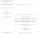
FIG. 1 is a flow chart of a method for adaptive pin-positioning and plugging of a three-pin electronic component according to embodiment 1 of the present invention;
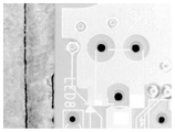
FIG. 2 is a PCB image obtained by image acquisition;
FIG. 3 is a partial sectional view of an insertion hole site;
FIG. 4 is a partial screenshot of filtered insertion hole locations;
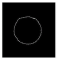
FIG. 5 is a partial screenshot of the insertion hole site after edge extraction;
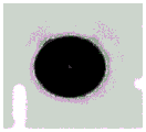
FIG. 6 is a partial screenshot of the insertion hole site after the edge shape fitting;
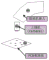
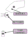
FIG. 7 is a schematic diagram of the actual installation position of the upper camera in practical application;
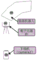
FIG. 8 is a schematic diagram of an actual installation position of a lower camera in an actual application;
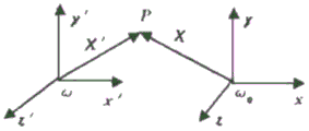
FIG. 9 shows ω and ω0A schematic diagram of coordinate transformation relationship existing between the two;
FIG. 10 is a schematic diagram of pin length photographing;
FIG. 11 is a flowchart of a method for adaptive pin-based positioning and mounting of a three-pin electronic component according to embodiment 3 of the present invention;
FIG. 12 is a block diagram of a pin adaptive positioning and mounting system embodiment 5 of a three-pin electronic component in accordance with the present invention;
fig. 13 is a block diagram of a pin adaptive positioning and mounting system 6 for a three-pin electronic component according to an embodiment of the present invention.
Detailed Description
The technical solutions in the embodiments of the present invention will be clearly and completely described below with reference to the drawings in the embodiments of the present invention, and it is obvious that the described embodiments are only a part of the embodiments of the present invention, and not all of the embodiments. All other embodiments, which can be derived by a person skilled in the art from the embodiments given herein without making any creative effort, shall fall within the protection scope of the present invention.
The invention aims to provide a pin self-adaptive positioning and plugging method and a pin self-adaptive positioning and plugging system for a three-pin electronic component, which can enable a special-shaped electronic component with a large pin pitch error to be normally used for automatic plugging operation.
In order to make the aforementioned objects, features and advantages of the present invention comprehensible, embodiments accompanied with figures are described in further detail below.
Example 1
Fig. 1 is a flowchart of a method for adaptive pin positioning and plugging of a three-pin electronic component 1 according to an embodiment of the present invention. Referring to fig. 1, the pin adaptive positioning and plugging method for the three-pin electronic component includes: step 101: acquiring an image of each insertion hole on the circuit board, and calculating the center position coordinates and the radius of each insertion hole on the circuit board according to the image of each insertion hole.
Step 102: and acquiring a pin image of the electronic component, and calculating the center position coordinates of the tail end of each pin and the radius of the tail end of each pin according to the pin image.
Step 103: and judging whether the radius of the tail end of the maximum pin is smaller than the radius of the minimum insertion hole or not to obtain a first judgment result. If the first judgment result shows that the radius of the tail end of the maximum pin is smaller than the radius of the minimum plug-in hole, executing step 104; if the first determination result indicates that the radius of the maximum pin end is greater than or equal to the radius of the minimum insertion hole, step 110 is executed.
Step 104: and sequentially judging whether any point on the edge of the tail end of each pin is in a circle formed by fitting the edges of the insertion holes corresponding to the pins or not to obtain a second judgment result. If the second judgment result indicates that any point on the edge of the tail end of each pin is in a circle formed by fitting the edge of the insertion hole corresponding to the pin, executing step 105; if the second determination result indicates that any point on the edge of the tail end of each lead is outside the circle formed by fitting the edge of the insertion hole corresponding to the lead, step 106 is executed.
Step 105: and sending a vertical plug-in command to the robot to control the robot to vertically plug in the three pins.
Step 106: determining the category of the deformed pins according to the length value of each pin; the category of the deformed pins comprises a longest pin, a next longest pin and a shortest pin; the deformation pins are pins outside circles formed by fitting any point on the edges of the tail ends of the pins at the edges of the insertion holes corresponding to the pins.
Before executing the step of determining the category of the deformed pins according to the length values of the pins, the method further comprises the following steps: and sending a first rotation instruction to the robot to control the robot to rotate the electronic component until the pin is in the horizontal direction. Acquiring a horizontal pin image, and calculating the length value of each pin according to the horizontal pin image. And sending a second rotation instruction to the robot to control the robot to rotate the electronic component to recover to a pin-down state.
Step 107: if the deformation pin is the longest pin, sending a first moving instruction to the robot to control the robot to move the electronic component to a position right above the center position of the insertion hole corresponding to the deformation pin according to the first moving instruction; calculating a first length difference value between the deformation pin and the second long pin, and sending the first length difference value to the robot to control the robot to move the electronic component downwards according to the first length difference value and vertically insert the deformation pin; and then calculating a first midpoint position coordinate of a connecting line between the center position of the tail end of the next long pin and the center position of the tail end of the shortest pin, and a second midpoint position coordinate of a connecting line between the center position of the insertion hole corresponding to the next long pin and the center position of the insertion hole corresponding to the shortest pin, and sending a first coordinate difference value of the first midpoint position coordinate and the second midpoint position coordinate to the robot so as to control the robot to move the electronic component according to the first coordinate difference value and vertically insert the next long pin and the shortest pin.
In this step 107, the first movement command specifically includes a first movement amount and a first movement direction; the first movement amount is a first difference value between the center position coordinates of the insertion holes corresponding to the deformation pins and the center position coordinates of the tail ends of the deformation pins; the first moving direction is determined by the sign of the first difference.
Step 108: if the deformation pin is the second-long pin, sending a second moving instruction to the robot to control the robot to move the electronic component according to the second moving instruction until the longest pin is positioned right above the center position of the insertion hole corresponding to the longest pin; calculating a second length difference value between the longest pin and the deformed pin, and sending the second length difference value to the robot to control the robot to move downwards according to the second length difference value and vertically insert the longest pin; then sending the first moving instruction to a robot to control the robot to move the electronic component to a position right above the center position of the insertion hole corresponding to the deformation pin according to the first moving instruction; calculating a third length difference value between the deformed pin and the shortest pin, and sending the third length difference value to the robot to control the robot to move downwards according to the third length difference value and vertically insert the deformed pin; and finally, sending a third moving instruction to the robot to control the robot to move the electronic component according to the third moving instruction until the shortest pin is positioned right above the center position of the insertion hole corresponding to the shortest pin, and vertically inserting the shortest pin.
In this step 108, the second movement instruction specifically includes a second movement amount and a second movement direction; the second movement amount is a second difference value between the center position coordinate of the insertion hole corresponding to the longest pin and the center position coordinate of the tail end of the longest pin; the second moving direction is determined by the sign of the second difference. The third movement instruction specifically includes a third movement amount and a third movement direction; the third movement amount is a third difference value between the center position coordinate of the insertion hole corresponding to the shortest pin and the center position coordinate of the tail end of the shortest pin; the third moving direction is determined by the sign of the third difference.
Step 109: if the deformed pin is the shortest pin, calculating a third midpoint position coordinate of a connecting line between the center position of the tail end of the longest pin and the center position of the tail end of the second longest pin, and a fourth midpoint position coordinate of a connecting line between the center position of the insertion hole corresponding to the longest pin and the center position of the insertion hole corresponding to the second longest pin, and sending a second coordinate difference value of the third midpoint position coordinate and the fourth midpoint position coordinate to the robot so as to control the robot to move the electronic component according to the second coordinate difference value; calculating a fourth length difference value between the second-longest pin and the deformation pin, and sending the fourth length difference value to the robot to control the robot to move the electronic component downwards according to the fourth length difference value, and vertically inserting the longest pin and the second-longest pin; and then sending the first moving instruction to a robot to control the robot to move the electronic component to a position right above the center position of the insertion hole corresponding to the deformation pin according to the first moving instruction, and vertically inserting the deformation pin.
Step 110: and sending an insertion failure instruction to the robot to control the robot to discard the electronic components.
In this embodiment the robot is a six degree of freedom card robot.
Example 2:
the pin self-adaptive positioning and inserting method for the electronic component with soft pins specifically comprises the following steps: identifying and extracting characteristic points in the image of the insertion hole: the method specifically comprises the steps of filtering the image, extracting the edge of the image and fitting the edge shape. Wherein the filtering of the image comprises: the image of the PCB obtained by image acquisition is shown in figure 2, the local screenshot of the insertion hole site is shown in figure 3, and it can be seen from figure 3 that more noise exists around the insertion hole and the extraction of the edge of the insertion hole site has larger interference, so the algorithm calculates the average gray value of the neighborhood around the sampling image point and replaces the gray value of the current sampling point with the average value. Assuming that P (x, y) is an original image of N × N and an image obtained by using the present algorithm is P' (x, y), the filtering algorithm of the image can be expressed as follows:

where S is the set of neighborhoods centered at (x, y) and M is the sum of the number of neighborhoods centered at (x, y). As can be seen from the expression (1), the larger the value of M is, the more obvious the filtering effect of the finally obtained image is but the more blurred the image is, so that the value needs to try the effect generated by different values in practice. The system is more suitable to take 8 out, that is, the average gray value of the original image is calculated by using the neighborhood with the size of 3 multiplied by 3, and the gray value of the current sampling point is replaced by the average value, so that the effect of filtering the original image is achieved. According to the method, the image in fig. 3 is processed as shown in fig. 4, and a good filtering effect is obtained.
The edge extraction of the image comprises: in theory, the edge extraction of the image is generally realized by performing gradient operation on the image. The image gradient can be expressed by the following arithmetic expression: g (x, y) ═ dx (i, j) + dy (i, j); wherein dx and dy are the deviation values of the gray values between the adjacent pixels; the larger the value of G (x, y) is, the more drastic the gray level change of pixels is, and the target edge can be obtained by applying appropriate threshold value limitation; common gradient algorithms are Sobel, Scharr and Lapacian, where the Sobel algorithm is used, and the typical filter kernel of Sobel is:

s is visible in the formula (2)xIt is the filter kernel in the X direction, then the filter kernel in the Y direction should be Sy=SxT; the image obtained after filtering (i.e. the image shown in fig. 4) is subjected to image convolution operation with the filtering kernel shown in the formula (2), and the threshold of low pass 80 and high pass 100 is selected to obtain the image shown in fig. 5. As can be seen from fig. 5, the required edge image can be obtained well after the edge extraction.
The fitting of the edge shape includes: the fitting process is to obtain the center position of the insertion hole according to the edge image. In fig. 5, an approximately circular hole is obtained, and what we need to obtain is the center position of the insertion hole, that is, at this moment we need to perform edge shape fitting to realize the calculation of the coordinates of the approximate center of the non-circle in fig. 5.
The standard equation for a circle is: (x-a)2+(y-b)2=r2(3)
Set point (x)i,yi) i belongs to (1,2,3,4.. N) as a point needing fitting, and the distance from the center of the circle is diThen, there are:
di2=(xi-a)2+(yi-b)2(4)
point (x)i,yi) The square difference value of the distance from i epsilon (1,2,3,4.. N) to the center of the circle and the radius of the circle is as follows:
i=di 2-r2=(xi-a)2+(yi-b)2-r2(5)
let a be-2 a; b ═ 2B; c ═ a2+b2-r2Expanding the expression (5) to obtain:
i=xi 2+yi 2+Axi+Byi+C (6)
let F (A, B, C) beiSum of squares of (c):
F(A,B,C)=∑i 2=∑[(xi 2+yi 2+Axi+Byi+C)]2(7)
x in the above (3), (4), (5), (6) and (7)iAnd yiSince the parameters a, B, C are known, the expression of the circle can be found by finding the parameters a, B, C so that the value of F (a, B, C) is the minimum. Here, it is represented by formula (8).
(x-X1)2+(y-Y1)2-r2=0 (8)
The results of the fitted images are shown in fig. 6; according to the principle, the pin center coordinates of the components can be fitted. The center coordinates of the circle can be found from the expression (8) of the circle: pt1(X1,Y1);
Let Pw1(Xw1,Yw1,Zw1) The point is the central position P of the insertion holet1(X, Y) coordinate values in the robot coordinate system; then there is [ X ]w1,Yw1,Zw1]=A[X1,Y1,0]T (9), and P can be obtained by calculation according to the formula (9)w1(Xw1,Yw1,Zw1) And (4) point. In equation (9), a is a transformation matrix between the camera1 and the coordinate system of the cartridge manipulator. The upper camera is fixed on the arm of the robot, and the lower camera is fixed outside the robot and does not move along with the robot. Fig. 7 shows the actual installation position of the upper camera in practical application; fig. 8 shows the actual installation position of the lower camera in practical application. The solving process of A is as follows: calibrating a camera coordinate system and a plug-in robot coordinate system: the calibration of the camera coordinate system and the coordinate system of the plug-in robot can be simply understood as coordinate transformation, and the coordinate transformation is commonly used for describing the mutual pose relationship between objects. Through the coordinate transformation relation between the rectangular coordinate systems, the description of any space point in one coordinate system can be converted into the description in the other coordinate system. As shown in fig. 9, at ω and ω0There is a coordinate transformation relationship A between so that at ω0Any point P in the lower space is fullExpression of the paw under ω. The expression may be abbreviated as X' ═ AX (10). Wherein X '═ X', y ', z', 1]T is the expression of point P under ω, X ═ X, y, z,1]T is point P at ω0Expression of (a) below. Since the camera coordinate system is a plane coordinate system, the expression in (10) can be rewritten as: x ' ═ RX + M (11), where X ' ═ X ', y ', z ']T is the expression of point P under ω, X ═ X, y, z]T is point P at ω0Expression of (a) below. According to the theory, the expression A in the expression (10) can be obtained only by listing the corresponding same point expressions in the three groups of plug-in robots and cameras. And finding out the coordinates of the three characteristic points in the visual field range of the camera and the coordinates of the three points in the coordinate system of the inserting robot. The following set of equations is listed:

(X) in the above equation set (12)0,Y0)、(X1,Y1)、(X2,Y2) And (X)0’,Y0’)、(X1’,Y1’)、(X2’,Y2') are known quantities, and the transformation matrix A between the upper camera1 and the plug-in robot coordinate system is derived from equation set (12) above as:

the transformation matrix a' between the lower Camera2 and the plug-in robot coordinate system is:

let PT2(X2,Y2) Is the coordinate of any point on the image circle, PW2(XW2,YW2,Zw2) Is PT2Coordinate values in the plug-in robot coordinate system; then there is [ X ]w2,Yw2,Zw2]=A[X2,Y2,0]T(15)。
P can be obtained by the calculation of (15)w2(Xw2,Yw2,Zw2) And (4) point.
Knowing the coordinates of the center of the circle and one point on the circle, the radius of the circle can be obtained; let R1For the radius of PCB board 1# cartridge hole, then have: r1=sql((Xw1-Xw2)2+(Yw1-Yw2)2)。
The calculation process of the pins of the special-shaped electronic component is similar to the calculation process of the position coordinates and the hole sizes of the insertion holes of the PCB, and the central position coordinates P of the tail ends of the pins of the component can be calculated by the same principlewi’(Xwi’,Ywi’,Zwi') point and pin end radius Ri' (where i ═ 0,1, 2).
Whether the pins can be quickly inserted in place vertically at one time is judged: by taking a picture as shown in fig. 7 and calculating according to the above process, the size of the insertion hole of the PCB, that is, the radius R, can be obtainedi(where i is 0,1, 2); then, the electronic component pins are photographed as shown in FIG. 8, so that the size R of each pin can be obtained quicklyi' (where i ═ 0,1, 2). When the following conditions are satisfied: max (R)i’)<Min(Ri) And (16), smoothly entering the following insertion link, otherwise, finishing the insertion operation. At this time, three pins of the electronic component are named as: a 1# pin, a 2# pin and a 3# pin; three inserting hole sites on the PCB are named as: 1# well, 2# well and 3# well.
At this time, let Mi(xm,ym) The point on the edge of the 1# pin and the circle fitted to the edge of the 1# hole are: (x)i-A)2+(yi-B)2-Ri 2(0), (17), point Mi(xm,ym) Substituting into the expression (17) should satisfy: (x)m-A)2+(ym-B)2-Ri 2<0 (18); if the formula (18) is not satisfied, the insertion work cannot be completed quickly. 2# pin, hole and 3# pin, hole calculation methodPushing; if all the pin data can be calculated by the above equations (17) and (18), it can be determined that the insertion robot can quickly and vertically complete the insertion operation.
When the arithmetic expression (18) is not satisfied, the inserting posture of the inserting robot is dynamically adjusted to complete the inserting operation of the pin soft element.
As shown in fig. 10, the pin length of the photographing element can be realized by adjusting the photographing posture of the robot. The plug-in robot drives the pins of the electronic components, so that the pins of the components are arranged in the horizontal direction, and the pin lengths of the components can be obtained by taking a picture at one time. By the posture shown in fig. 10, it is equivalent to photographing the component pins from the side, and the length information of the pins of the electronic component can be obtained. Since the pin-down state needs to be restored before the insertion operation, after the pin lengths of the components are obtained by photographing, the posture of the insertion robot needs to be adjusted to be restored to the posture shown in fig. 8, that is, the photographing posture with the pin of the component down is restored.
For example, if the 2# pin does not satisfy the expression (18), it is described that the 2# pin may be deformed, that is, the problem of displacement in the plane is solved, and the plugging operation can be completed theoretically only by completing the displacement correcting action of the 2# pin, but at this point, the length information of 3 pins needs to be calculated first;
let HiThe length value of the pin, D is the thickness of the PCB plate, and the following expression is given:
Max(Hi)<=H2(19)
Min(Hi)>=H2(20)
when expression (19) is satisfied and the difference between the lengths of the No. 2 pin and the next-long pin is H', the process has already found the center position coordinate P of the PCB board inserting hole with the No. 2 pin and the No. 2 hole as the referencewi(Xwi,Ywi,Zwi) And the pin end center position coordinates P of each pinwi’(Xwi’,Ywi’,Zwi') wherein i is 1,2, 3. The inserting manipulator of the inserting robot moves to the position right above the center of the No. 2 hole, and the No. 2 inserting hole and the No. 2 pin of the PCB are seatedThe index difference value is a movement amount, the sign of the difference value between the coordinates of the insertion hole and the pin is a movement direction, then the upper surface of the PCB is 0, the vertical line of the upper surface of the PCB is a movement axial direction, the plug-in robot drives the component to move-H' + alpha, and alpha is an allowable clearance fit adjustment value and is 2 times greater than the theoretical precision of the plug-in robot in practical application.
Next, the midpoint P of the center line of the 1# and 3# insertion holes was calculatedc13(Xa1, Ya1), midpoint P of the line connecting the centers of pin # 1 and pin # 3c13' (Xa2, Ya2) is as follows:
Xa1=(Xw1+Xw3)/2;
Ya1=(Yw1+Yw3)/2;
Xa2=(Xw1’+Xw3’)/2;
Ya2=(Yw1’+Yw3’)/2;
after the component is driven by the plug-in robot to move (Xa2-Xa1, Ya2-Ya1), the pins 1# and 3# can be moved to the upper positions of the plug-in holes respectively; the Z-axis coordinate is not considered here because the 2# pin is already in the hole at this time, and the Z-axis cannot be changed.
Finally, the component is driven by the component inserting robot to move downwards by D + m by taking the vertical line of the upper surface of the PCB as the moving axial direction, m is an actual machine adjusting value, the larger the value of m is, the more stable the component is inserted into the component is, but the length of a pin of the component cannot be exceeded, and Min (H) is arranged at the positioni)>m is more than or equal to 0, thus completing the plug-in mounting operation process of the component.
When expression (20) is satisfied, and the difference between the lengths of the No. 2 pin and the second-shorter pin is H ', calculating the midpoint of the central connecting line of the No. 1 and No. 3 holes and the midpoint of the central connecting line of the No. 1 and No. 3 pins by a method similar to the method mentioned above, moving the inserting manipulator to the position right above the midpoint of the central connecting line of the No. 1 and No. 3 holes, then taking the upper surface of the PCB as 0 and the vertical line of the upper surface of the PCB as the moving axial direction, moving-H' + alpha, alpha which is 2 times greater than the theoretical precision of the inserting robot in practical application, then moving the inserting manipulator to the position right above the central position of the No. 2 hole by taking the No. 2 pin and the No. 2 hole as the reference, and the difference between the coordinates of the No. 2 inserting hole and the NoThe movement amount, the symbol of the difference value of the coordinates of the insertion holes and the pins are taken as the movement direction, finally, the component is driven by the plug-in robot, the vertical line on the upper surface of the PCB is taken as the movement axial direction, the component moves downwards by D + m, m is an actual debugging value, the larger the value of m is, the more stable the component is inserted is, but the length of the pins of the component cannot be exceeded, and Min (H) (the length of the pins of the component) isi)>m is more than or equal to 0), thus completing the plug-in mounting operation process of the component.
When the expressions (19) and (20) are not satisfied, calculating the index n of the longest pin, and obtaining the length difference between the index n and the 2# pin as H ', and the length difference between the 2# pin and the last pin as H ", then taking the n # pin and the n # hole as the reference, moving the inserting mechanical arm to the position right above the n # hole, taking the coordinate difference between the inserting hole of the PCB and the pin as the moving amount, taking the symbol of the difference between the inserting hole and the pin as the moving direction, then taking the upper surface of the PCB as 0, taking the vertical line of the upper surface of the PCB as the moving axial direction, moving-H' + alpha, alpha being more than 2 times of the theoretical precision of the inserting robot in practical application, then taking the 2# pin and the 2# hole as the reference, lowering the inserting robot again to-H" height on the basis of the current height, and similarly translating the robot on the basis of the corresponding to the inserting pin inserted with the last pin, finally, D + m is reduced (m is the actual debugging value, the element is inserted more stably when the value of m is larger, but the length of the pin of the element cannot be exceeded, and Min (H) is obtainedi)>m is more than or equal to 0), thus completing the plug-in mounting operation process of the component.
In this embodiment the robot is a six degree of freedom card robot.
Through actual production test, the pin self-adaptive positioning and plugging method for the electronic component with soft pins is very effective in plugging the electronic component with soft pins, greatly improves the yield and the first pass rate of plugging operation, and effectively reduces the loss of the special-shaped electronic component.
Example 3
Fig. 11 is a flowchart of a method for adaptive pin positioning and mounting of a three-pin electronic component according to embodiment 3 of the present invention. Referring to fig. 11, the pin adaptive positioning and mounting method for the three-pin electronic component includes:
step 1101: acquiring an image of each insertion hole on the circuit board, and calculating the center position coordinates and the radius of each insertion hole on the circuit board according to the image of each insertion hole.
Step 1102: and acquiring a pin image of the electronic component, and calculating the center position coordinates of the tail end of each pin and the radius of the tail end of each pin according to the pin image.
Step 1103: and judging whether the radius of the tail end of the maximum pin is smaller than the radius of the minimum insertion hole or not to obtain a first judgment result. If the first judgment result indicates that the radius of the tail end of the maximum pin is smaller than the radius of the minimum insertion hole, executing step 1104; if the first determination result indicates that the radius of the maximum pin end is greater than or equal to the radius of the minimum insertion hole, step 1114 is executed.
Step 1104: and sequentially judging whether any point on the edge of the tail end of each pin is in a circle formed by fitting the edges of the insertion holes corresponding to the pins or not to obtain a second judgment result. If the second determination result indicates that any point on the edge of the tail end of each lead is in a circle formed by fitting the edge of the insertion hole corresponding to the lead, executing step 1105; if the second determination result indicates that any point on the edge of the tail end of each lead is outside the circle formed by fitting the edge of the insertion hole corresponding to the lead, step 1106 is executed.
Step 1105: and sending a vertical plug-in command to the robot to control the robot to vertically plug in the three pins.
Step 1106: and fitting a plane equation of the central positions of the tail ends of the three pins according to the central position coordinates of the tail ends of the pins.
Step 1107: and calculating a plane normal vector according to the plane equation.
Step 1108: respectively taking a unit vector on an X axis, a Y axis and a Z axis, and calculating a first included angle, a second included angle and a third included angle formed by the plane and the X axis, the Y axis and the Z axis by using a line-surface angle formula.
Step 1109: and sending an X-axis rotation instruction, a Y-axis rotation instruction and a Z-axis rotation instruction to the robot so as to control the robot to rotate the electronic component in the X-axis direction according to the first included angle, rotate the electronic component in the Y-axis direction according to the second included angle and rotate the electronic component in the Z-axis direction according to the third included angle.
Step 1110: and obtaining the pin image of the rotated electronic component, and calculating the coordinate of any point on the edge of the tail end of each pin of the rotated electronic component according to the pin image of the rotated electronic component.
Step 1111: and sequentially judging whether any point on the edge of the tail end of each pin of the rotated electronic component is in a circle formed by fitting the edges of the insertion holes corresponding to the pins, so as to obtain a third judgment result. If the third determination result indicates that any point on the edge of the tail end of each pin of the electronic component after rotation is in the circle formed by fitting the edge of the insertion hole corresponding to the pin, executing step 1112; and if the third judgment result shows that any point on the tail end edge of each pin of the electronic component after rotation is outside the circle formed by fitting the edge of the insertion hole corresponding to the pin, executing the step 1113.
Step 1112: and sending a vertical plug-in command to the robot to control the robot to vertically plug in the three pins.
Step 1113: and sending an insertion failure instruction to the robot to control the robot to discard the electronic components.
Step 1114: and sending an insertion failure instruction to the robot to control the robot to discard the electronic components.
In this embodiment the robot is a six degree of freedom card robot.
Example 4:
compared with the pin adaptive positioning and plugging method for the electronic component with hard pins in embodiment 2, the pin adaptive positioning and plugging method for the electronic component with soft pins is different in the step after the expression (18) is not established. According to the pin self-adaptive positioning and inserting method for the electronic component with the hard pins, after the expression (18) is not established, the inserting posture of the inserting robot is dynamically adjusted to complete the inserting operation of the component with the hard pins. When the pins of the electronic component are hard, the pins cannot be corrected by the plug-in robot (embodiment 2)) In the meantime, it is necessary to continue to take a picture in the posture shown in fig. 10, calculate the length value of each pin, and by combining the pin coordinates calculated above, it can be obtained that the coordinate values of the pin vertex (end) center of the electronic component to be plugged are: p1(X1,Y1,Z1),P2(X2,Y2,Z2),P3(X3,Y3,Z3) And calculating a plane formed by the tail ends of the pins of the electronic component according to the coordinate values, and fitting a plane equation where the three points are located:
ax+by+cz+d=0 (21)
the normal vector of the plane can be found by the expression (21) as:
T=(a,b,c) (22)
then, a unit vector (1, 0, 0) is taken on the X axis, and the plane P can be calculated by using the formula of line-plane angle1P2P3The included angles alpha with the X axis can be obtained by the same principle as the included angles beta and gamma with the Y axis and the Z axis.
The original photographing coordinate of the plug-in robot is set as PP(x, y, z, a, b, c); from the coordinate definition of the robot, it follows: x is a component in the X direction of the plug-in robot; y is a component in the Y direction of the plug-in robot; z is a component of the plug-in robot in the Z direction; a is the rotation component of the cartridge robot in the X-axis direction; b is the component of the rotation of the plug-in robot in the Y-axis direction; c is the component of the Z-axis direction rotation of the plug-in robot; let the robot coordinate after the attitude adjustment be PP' (x ', y ', z ', a ', b ', c '); then x' ═ x; y' ═ y; z ═ z; a' ═ a + α; b' ═ b + β; c' ═ c + γ.
The shooting posture of the plug-in robot can be easily adjusted by utilizing the calculated alpha, beta and gamma, namely the plug-in robot is moved to the coordinate PP' (x ', y ', z ', a ', b ', c ') can reach the pose where the plane formed by the pin vertex (tail end) center of the electronic component is parallel to the plane of the PCB, at this time, the lower camera is used again to photograph the pins of the component, then the newly obtained point coordinates are respectively substituted into the expressions (17) and (18) in the embodiment 2 to be recalculated, if the point coordinates meet the requirements, the vertical insertion is finished with the current pose, and if the point coordinates meet the requirements, the expressions are inserted into the PCB verticallyIf not, the electronic component can only be plugged in after being corrected by other methods.
When the expression (18) is not satisfied, it represents that the component cannot be vertically inserted, and the insertion operation can be finally realized only by the method of correcting the pins in embodiment 2 or the method of judging whether the three pins can be inserted into the holes adaptively in the plane formed by the vertices (ends) of the three pins in embodiment 4.
In this embodiment the robot is a six degree of freedom card robot.
The pin self-adaptive positioning and inserting method for the electronic component with the harder pins is very effective in inserting the electronic component with the harder pins, and greatly improves the accuracy of inserting operation.
Example 5
Fig. 12 is a block diagram of embodiment 5 of a pin adaptive positioning system for a three-pin electronic component. Referring to fig. 12, the pin-adaptive positioning and mounting system for three-pin electronic components includes:
the insertion hole image acquiring module 1201 is configured to acquire an insertion hole image on a circuit board, and calculate a center position coordinate of each insertion hole and a radius of each insertion hole on the circuit board according to the insertion hole image.
The pin image obtaining module 1202 is configured to obtain a pin image of the electronic component, and calculate a coordinate of a center position of each pin end and a radius of each pin end according to the pin image.
The first determining module 1203 is configured to determine whether the radius of the tail end of the maximum pin is smaller than the radius of the minimum insertion hole, so as to obtain a first determining result.
A second determining module 1204, configured to sequentially determine whether any point on the edge of the tail end of each pin is within a circle formed by fitting the edges of the insertion holes corresponding to the pins when the output result of the first determining module is that the radius of the tail end of the maximum pin is smaller than the radius of the minimum insertion hole, so as to obtain a second determining result.
And the first pin direct-insertion module 1205 is configured to send a vertical insertion instruction to the robot to control the robot to vertically insert three pins when the output result of the second judgment module is that any point on the edge of the tail end of each pin is in a circle formed by fitting the edge of the insertion hole corresponding to the pin.
A deformed pin category determining module 1206, configured to determine a category of a deformed pin according to a length value of each pin when an output result of the second determining module is that any point on an edge of a tail end of each pin is outside a circle formed by fitting edges of the insertion holes corresponding to the pins; the category of the deformed pins comprises a longest pin, a next longest pin and a shortest pin; the deformation pins are pins outside circles formed by fitting any point on the edges of the tail ends of the pins at the edges of the insertion holes corresponding to the pins.
A first correction pin insertion module 1207, configured to send a first movement instruction to the robot to control the robot to move the electronic component according to the first movement instruction until the deformation pin is located right above a center position of the insertion hole corresponding to the deformation pin when an output result of the deformation pin type determination module is that the deformation pin is the longest pin; calculating a first length difference value between the deformation pin and the second long pin, and sending the first length difference value to the robot to control the robot to move the electronic component downwards according to the first length difference value and vertically insert the deformation pin; and then calculating a first midpoint position coordinate of a connecting line between the center position of the tail end of the next long pin and the center position of the tail end of the shortest pin, and a second midpoint position coordinate of a connecting line between the center position of the insertion hole corresponding to the next long pin and the center position of the insertion hole corresponding to the shortest pin, and sending a first coordinate difference value of the first midpoint position coordinate and the second midpoint position coordinate to the robot so as to control the robot to move the electronic component according to the first coordinate difference value and vertically insert the next long pin and the shortest pin.
A second correction pin insertion module 1208, configured to send a second movement instruction to the robot to control the robot to move the electronic component according to the second movement instruction until the longest pin is located right above the center position of the insertion hole corresponding to the longest pin when the output result of the deformation pin type determination module is that the deformation pin is the next-longest pin; calculating a second length difference value between the longest pin and the deformed pin, and sending the second length difference value to the robot to control the robot to move downwards according to the second length difference value and vertically insert the longest pin; then sending the first moving instruction to a robot to control the robot to move the electronic component to a position right above the center position of the insertion hole corresponding to the deformation pin according to the first moving instruction; calculating a third length difference value between the deformed pin and the shortest pin, and sending the third length difference value to the robot to control the robot to move downwards according to the third length difference value and vertically insert the deformed pin; and finally, sending a third moving instruction to the robot to control the robot to move the electronic component according to the third moving instruction until the shortest pin is positioned right above the center position of the insertion hole corresponding to the shortest pin, and vertically inserting the shortest pin.
A third correction pin insertion module 1209, configured to calculate, when an output result of the deformed pin type determination module is that the deformed pin is the shortest pin, a third midpoint position coordinate of a line connecting a center position of a longest pin end and a center position of a second longest pin end, and a fourth midpoint position coordinate of a line connecting a center position of an insertion hole corresponding to the longest pin and a center position of an insertion hole corresponding to the second longest pin, and send a second coordinate difference value between the third midpoint position coordinate and the fourth midpoint position coordinate to the robot to control the robot to move the electronic component according to the second coordinate difference value; calculating a fourth length difference value between the second-longest pin and the deformation pin, and sending the fourth length difference value to the robot to control the robot to move the electronic component downwards according to the fourth length difference value, and vertically inserting the longest pin and the second-longest pin; and then sending the first moving instruction to a robot to control the robot to move the electronic component to a position right above the center position of the insertion hole corresponding to the deformation pin according to the first moving instruction, and vertically inserting the deformation pin.
The first discarding module 1210 is configured to send a non-plugging instruction to the robot to control the robot to discard the electronic component when an output result of the first determining module is that the radius of the maximum pin end is greater than or equal to the radius of the minimum plugging hole.
This three pin electronic components's pin self-adaptation location cartridge system still includes:
and the pin rotating module is used for sending a first rotating instruction to the robot so as to control the robot to rotate the electronic component until the pin is positioned in the horizontal direction.
And the pin length value calculation module is used for acquiring a horizontal pin image and calculating the length value of each pin according to the horizontal pin image.
And the pin recovery module is used for sending a second rotation instruction to the robot so as to control the robot to rotate the electronic component to recover to a pin-down state.
In this embodiment the robot is a six degree of freedom card robot.
Example 6
Fig. 13 is a block diagram of a pin adaptive positioning and mounting system 6 for a three-pin electronic component according to an embodiment of the present invention. Referring to fig. 13, the pin-adaptive positioning and mounting system for three-pin electronic components includes:
the insertion hole image acquisition module 1301 is configured to acquire an insertion hole image on a circuit board, and calculate a center position coordinate of each insertion hole and a radius of each insertion hole on the circuit board according to the insertion hole image.
The pin image obtaining module 1302 is configured to obtain a pin image of the electronic component, and calculate a coordinate of a center position of each pin end and a radius of each pin end according to the pin image.
And the first judging module 1303 is used for judging whether the radius of the tail end of the maximum pin is smaller than that of the minimum insertion hole to obtain a first judging result.
And a second judging module 1304, configured to, when the output result of the first judging module is that the radius of the tail end of the maximum pin is smaller than the radius of the minimum insertion hole, sequentially judge whether any point on the edge of the tail end of each pin is within a circle formed by fitting the edges of the insertion holes corresponding to the pins, and obtain a second judging result.
The first pin direct-insertion module 1305 is configured to send a vertical insertion instruction to the robot to control the robot to vertically insert three pins when an output result of the second determining module is that any point on an edge of the tail end of each pin is within a circle formed by fitting edges of insertion holes corresponding to the pins.
And a plane equation fitting module 1306, configured to fit, according to the coordinates of the center positions of the tail ends of the pins, a plane equation where the center positions of the tail ends of the three pins are located, when an output result of the second determining module is that any point on the edge of the tail end of each pin is outside a circle formed by fitting the edge of the insertion hole corresponding to the pin.
And a normal vector calculation module 1307, configured to calculate a plane normal vector according to the plane equation.
And an included angle calculating module 1308, configured to respectively obtain a unit vector on the X axis, the Y axis, and the Z axis, and calculate a first included angle, a second included angle, and a third included angle, which are formed by the plane and the X axis, the Y axis, and the Z axis, by using a line-surface angle formula.
And the robot posture rotating module 1309 is used for sending an X-axis rotating instruction, a Y-axis rotating instruction and a Z-axis rotating instruction to the robot so as to control the robot to rotate the electronic component in the X-axis direction according to the first included angle, rotate the electronic component in the Y-axis direction according to the second included angle and rotate the electronic component in the Z-axis direction according to the third included angle.
And a rotated coordinate calculation module 1310 configured to obtain a pin image of the rotated electronic component, and calculate coordinates of any point on an edge of a tail end of each pin of the rotated electronic component according to the pin image of the rotated electronic component.
A third determining module 1311, configured to sequentially determine whether any point on the edge of the tail end of each pin of the rotated electronic component is within a circle formed by fitting the edges of the insertion holes corresponding to the pins, so as to obtain a third determination result.
And a second pin direct-insertion module 1312, configured to send a vertical insertion instruction to the robot to control the robot to vertically insert three pins when an output result of the third determining module is that any point on an edge of a tail end of each pin of the rotated electronic component is within a circle formed by fitting edges of insertion holes corresponding to the pins.
And a second discarding module 1313, configured to send an instruction that the electronic component cannot be plugged to the robot to control the robot to discard the electronic component when an output result of the third determining module is that any point on an edge of a tail end of each pin of the rotated electronic component is outside a circle formed by fitting edges of the plugging holes corresponding to the pins.
A first discarding module 1314, configured to send a non-plugging instruction to the robot to control the robot to discard the electronic component when the output result of the first determining module is that the radius of the tail end of the maximum pin is greater than or equal to the radius of the minimum plugging hole.
In this embodiment the robot is a six degree of freedom card robot.
The invention discloses a pin self-adaptive positioning and inserting method and a pin self-adaptive positioning and inserting system for a three-pin electronic component, aiming at the problem that rapid automatic inserting cannot be carried out due to the fact that the shape and the size parameters of a plurality of special-shaped electronic component pins are not standard in actual production, a machine vision and six-freedom-degree inserting robot are based on firstly collecting an inserting hole image of a PCB component, extracting the designated image information in the specific ROI to obtain the position data of the inserting holes of the PCB, then the image information right below the electronic component picked up by the robot and the image information of 3 directions of the side surface are analyzed, calculated and integrated, and the running data is sent to a six-degree-of-freedom plug-in robot, the plug-in robot runs the specific path to walk according to the given data, and finally the special-shaped electronic component is plugged in place, therefore, intelligent plug-in operation of the special-shaped electronic components is realized, and automatic rapid plug-in operation of the electronic components is realized. The pin self-adaptive positioning and plugging method and the pin self-adaptive positioning and plugging system for the three-pin electronic component are suitable for quick automatic plugging of the three-pin electronic component and automatic correction work of deformed pins, can greatly improve the production efficiency and the product quality, and thoroughly replace tedious and inefficient manual operation.
The invention discloses a pin self-adaptive positioning and plugging method and a pin self-adaptive positioning and plugging system for a three-pin electronic component, which aim to solve the problem that some special-shaped electronic components with larger pin spacing errors cannot be normally used for automatic plugging operation, 3D information of the pins of the components is reconstructed based on a machine vision algorithm, and the algorithm calculates the space posture required by a plugging robot to quickly complete accurate plugging of the components according to 3D space size information formed by the pins (3 pins) of the special-shaped components and the relative position and plane of a plugging hole position of a circuit board. If the special-shaped electronic component can not be directly and quickly inserted at one time, the algorithm firstly calculates that the insertion robot inserts one or two pins into insertion hole positions of the circuit board in a certain specific spatial attitude, and provides secondary spatial pose movement data of the insertion robot, generally translation and spatial rotation, so as to realize accurate insertion operation of the special-shaped electronic component.
The embodiments in the present description are described in a progressive manner, each embodiment focuses on differences from other embodiments, and the same and similar parts among the embodiments are referred to each other. For the system disclosed by the embodiment, the description is relatively simple because the system corresponds to the method disclosed by the embodiment, and the relevant points can be referred to the method part for description.
The principles and embodiments of the present invention have been described herein using specific examples, which are provided only to help understand the method and the core concept of the present invention; meanwhile, for a person skilled in the art, according to the idea of the present invention, the specific embodiments and the application range may be changed. In view of the above, the present disclosure should not be construed as limiting the invention.
Claims (9)
1. A pin self-adaptive positioning and plugging method for a three-pin electronic component is characterized by comprising the following steps:
acquiring an image of each insertion hole on a circuit board, and calculating the coordinates of the center position of each insertion hole and the radius of each insertion hole on the circuit board in a robot coordinate system according to the image of each insertion hole;
obtaining pin images of electronic components with soft pins, and calculating the central position coordinates of the tail ends of the pins and the radius of the tail ends of the pins in a robot coordinate system according to the pin images;
judging whether the radius of the tail end of the maximum pin is smaller than the radius of the minimum insertion hole or not to obtain a first judgment result;
if the first judgment result shows that the radius of the tail end of the maximum pin is smaller than the radius of the minimum insertion hole, sequentially judging whether any point on the edge of the tail end of each pin is in a circle formed by fitting the edges of the insertion holes corresponding to the pins to obtain a second judgment result;
if the second judgment result shows that any point on the edge of the tail end of each pin is in a circle formed by fitting the edge of the insertion hole corresponding to the pin, a vertical insertion instruction is sent to the robot to control the robot to vertically insert the three pins;
if the second judgment result shows that any point on the edge of the tail end of each pin is outside a circle formed by fitting the edge of the corresponding insertion hole of each pin, determining the type of the deformed pin according to the length value of each pin; the category of the deformed pins comprises a longest pin, a next longest pin and a shortest pin; the deformed pins are pins outside circles formed by fitting any point on the edges of the tail ends of the pins at the edges of the insertion holes corresponding to the pins;
if the deformation pin is the longest pin, sending a first moving instruction to the robot to control the robot to move the electronic component to a position right above the center position of the insertion hole corresponding to the deformation pin according to the first moving instruction; calculating a first length difference value between the deformation pin and the second long pin, and sending the first length difference value to the robot to control the robot to move the electronic component downwards according to the first length difference value and vertically insert the deformation pin; then, calculating a first midpoint position coordinate of a connecting line of the center position of the tail end of the next long pin and the center position of the tail end of the shortest pin in a robot coordinate system, and a second midpoint position coordinate of a connecting line of the center position of the insertion hole corresponding to the next long pin and the center position of the insertion hole corresponding to the shortest pin in the robot coordinate system, and sending a first coordinate difference value of the first midpoint position coordinate and the second midpoint position coordinate to the robot so as to control the robot to move the electronic component according to the first coordinate difference value and vertically insert the next long pin and the shortest pin;
if the deformation pin is the second-long pin, sending a second moving instruction to the robot to control the robot to move the electronic component according to the second moving instruction until the longest pin is positioned right above the center position of the insertion hole corresponding to the longest pin; calculating a second length difference value between the longest pin and the deformed pin, and sending the second length difference value to the robot to control the robot to move downwards according to the second length difference value and vertically insert the longest pin; then sending the first moving instruction to a robot to control the robot to move the electronic component to a position right above the center position of the insertion hole corresponding to the deformation pin according to the first moving instruction; calculating a third length difference value between the deformed pin and the shortest pin, and sending the third length difference value to the robot to control the robot to move downwards according to the third length difference value and vertically insert the deformed pin; finally, a third moving instruction is sent to the robot to control the robot to move the electronic component according to the third moving instruction until the shortest pin is positioned right above the center position of the inserting hole corresponding to the shortest pin, and the shortest pin is vertically inserted;
if the deformed pin is the shortest pin, calculating a third midpoint position coordinate of a connecting line of the center position of the tail end of the longest pin and the center position of the tail end of the next longest pin in a robot coordinate system and a fourth midpoint position coordinate of a connecting line of the center position of an insertion hole corresponding to the longest pin and the center position of an insertion hole corresponding to the next longest pin in the robot coordinate system, and sending a second coordinate difference value of the third midpoint position coordinate and the fourth midpoint position coordinate to the robot so as to control the robot to move the electronic component according to the second coordinate difference value; calculating a fourth length difference value between the second-longest pin and the deformation pin, and sending the fourth length difference value to the robot to control the robot to move the electronic component downwards according to the fourth length difference value, and vertically inserting the longest pin and the second-longest pin; then sending the first moving instruction to a robot to control the robot to move the electronic component to a position right above the center position of the insertion hole corresponding to the deformation pin according to the first moving instruction, and vertically inserting the deformation pin;
and if the first judgment result is negative, sending a plug-in incapable instruction to the robot to control the robot to discard the electronic component.
2. The method for pin adaptive positioning and plugging of a three-pin electronic component according to claim 1, wherein before the step of determining the type of the deformed pin according to the length value of each pin, the method further comprises:
sending a first rotation instruction to the robot to control the robot to rotate the electronic component until the pin is in the horizontal direction;
acquiring a horizontal pin image, and calculating the length value of each pin according to the horizontal pin image;
and sending a second rotation instruction to the robot to control the robot to rotate the electronic component to recover to a pin-down state.
3. The method for pin adaptive positioning and plugging of a three-pin electronic component according to claim 1, wherein the first movement command specifically includes a first movement amount and a first movement direction; the first movement amount is a first difference value between the center position coordinates of the insertion holes corresponding to the deformation pins and the center position coordinates of the tail ends of the deformation pins; the first moving direction is determined by the sign of the first difference.
4. The method for pin adaptive positioning and plugging of a three-pin electronic component according to claim 1, wherein the second movement command specifically includes a second movement amount and a second movement direction; the second movement amount is a second difference value between the center position coordinate of the insertion hole corresponding to the longest pin and the center position coordinate of the tail end of the longest pin; the second moving direction is determined by the sign of the second difference.
5. The method for pin adaptive positioning and plugging of a three-pin electronic component according to claim 1, wherein the third movement command specifically includes a third movement amount and a third movement direction; the third movement amount is a third difference value between the center position coordinate of the insertion hole corresponding to the shortest pin and the center position coordinate of the tail end of the shortest pin; the third moving direction is determined by the sign of the third difference.
6. A pin self-adaptive positioning and plugging method for a three-pin electronic component is characterized by comprising the following steps:
acquiring an image of each insertion hole on a circuit board, and calculating the center position coordinates and the radius of each insertion hole on the circuit board according to the image of each insertion hole;
obtaining a pin image of an electronic component with large pin pitch error, and calculating the center position coordinates of the tail end of each pin and the radius of the tail end of each pin according to the pin image;
judging whether the radius of the tail end of the maximum pin is smaller than the radius of the minimum insertion hole or not to obtain a first judgment result;
if the first judgment result shows that the radius of the tail end of the maximum pin is smaller than the radius of the minimum insertion hole, sequentially judging whether any point on the edge of the tail end of each pin is in a circle formed by fitting the edges of the insertion holes corresponding to the pins to obtain a second judgment result;
if the second judgment result shows that any point on the edge of the tail end of each pin is in a circle formed by fitting the edge of the insertion hole corresponding to the pin, a vertical insertion instruction is sent to the robot to control the robot to vertically insert the three pins;
if the second judgment result shows that any point on the edge of the tail end of each pin is outside a circle formed by fitting the edge of the corresponding insertion hole of each pin, fitting a plane equation of the central position of the tail end of the three pins according to the central position coordinates of the tail end of each pin;
calculating a plane normal vector according to the plane equation;
respectively taking a unit vector on an X axis, a Y axis and a Z axis, and calculating a first included angle, a second included angle and a third included angle formed by the plane and the X axis, the Y axis and the Z axis by using a line-surface angle formula;
sending an X-axis rotation instruction, a Y-axis rotation instruction and a Z-axis rotation instruction to the robot so as to control the robot to rotate the electronic component in the X-axis direction according to the first included angle, rotate the electronic component in the Y-axis direction according to the second included angle and rotate the electronic component in the Z-axis direction according to the third included angle;
obtaining a pin image of the rotated electronic component, and calculating the coordinate of any point on the edge of the tail end of each pin of the rotated electronic component according to the pin image of the rotated electronic component;
sequentially judging whether any point on the edge of the tail end of each pin of the rotated electronic component is in a circle formed by fitting the edges of the insertion holes corresponding to the pins or not to obtain a third judgment result;
if the third judgment result shows that any point on the tail end edge of each pin of the electronic component is in a circle formed by fitting the edge of the insertion hole corresponding to the pin after the rotation, a vertical insertion instruction is sent to the robot to control the robot to vertically insert the three pins;
if the third judgment result shows that any point on the tail end edge of each pin of the electronic component is outside a circle formed by fitting the edge of the insertion hole corresponding to the pin after the rotation, sending an insertion incapability instruction to the robot to control the robot to discard the electronic component;
and if the first judgment result shows that the radius of the tail end of the maximum pin is larger than or equal to the radius of the minimum insertion hole, sending an insertion-incapable instruction to the robot to control the robot to discard the electronic component.
7. The utility model provides a three pin electronic components's pin self-adaptation location cartridge system which characterized in that includes:
the system comprises a plug hole image acquisition module, a robot coordinate system and a data processing module, wherein the plug hole image acquisition module is used for acquiring plug hole images on a circuit board and calculating the coordinates of the center positions of plug holes and the radiuses of the plug holes on the circuit board in the robot coordinate system according to the plug hole images;
the pin image acquisition module is used for acquiring pin images of electronic components with soft pins and calculating the central position coordinates of the tail ends of the pins and the radius of the tail ends of the pins in a robot coordinate system according to the pin images;
the first judgment module is used for judging whether the radius of the tail end of the maximum pin is smaller than the radius of the minimum insertion hole or not to obtain a first judgment result;
the second judging module is used for sequentially judging whether any point on the tail end edge of each pin is in a circle formed by fitting the edges of the insertion holes corresponding to the pins or not when the output result of the first judging module is that the radius of the tail end of the maximum pin is smaller than the radius of the minimum insertion hole, so as to obtain a second judging result;
the first pin direct insertion module is used for sending a vertical insertion instruction to the robot to control the robot to vertically insert three pins when the output result of the second judgment module is that any point on the edge of the tail end of each pin is in a circle formed by fitting the edge of the insertion hole corresponding to the pin;
the deformed pin type determining module is used for determining the type of the deformed pin according to the length value of each pin when the output result of the second judging module is that any point on the tail end edge of each pin is outside a circle formed by fitting the edge of the insertion hole corresponding to the pin; the category of the deformed pins comprises a longest pin, a next longest pin and a shortest pin; the deformed pins are pins outside circles formed by fitting any point on the edges of the tail ends of the pins at the edges of the insertion holes corresponding to the pins;
the first correction pin insertion module is used for sending a first movement instruction to the robot to control the robot to move the electronic component according to the first movement instruction until the deformation pin is positioned right above the center position of the insertion hole corresponding to the deformation pin when the output result of the deformation pin type determination module is that the deformation pin is the longest pin; calculating a first length difference value between the deformation pin and the second long pin, and sending the first length difference value to the robot to control the robot to move the electronic component downwards according to the first length difference value and vertically insert the deformation pin; then, calculating a first midpoint position coordinate of a connecting line of the center position of the tail end of the next long pin and the center position of the tail end of the shortest pin in a robot coordinate system, and a second midpoint position coordinate of a connecting line of the center position of the insertion hole corresponding to the next long pin and the center position of the insertion hole corresponding to the shortest pin in the robot coordinate system, and sending a first coordinate difference value of the first midpoint position coordinate and the second midpoint position coordinate to the robot so as to control the robot to move the electronic component according to the first coordinate difference value and vertically insert the next long pin and the shortest pin;
the second correction pin insertion module is used for sending a second movement instruction to the robot to control the robot to move the electronic component according to the second movement instruction until the longest pin is positioned right above the center position of the insertion hole corresponding to the longest pin when the output result of the deformation pin type determination module is that the deformation pin is the next-longest pin; calculating a second length difference value between the longest pin and the deformed pin, and sending the second length difference value to the robot to control the robot to move downwards according to the second length difference value and vertically insert the longest pin; then sending the first moving instruction to a robot to control the robot to move the electronic component to a position right above the center position of the insertion hole corresponding to the deformation pin according to the first moving instruction; calculating a third length difference value between the deformed pin and the shortest pin, and sending the third length difference value to the robot to control the robot to move downwards according to the third length difference value and vertically insert the deformed pin; finally, a third moving instruction is sent to the robot to control the robot to move the electronic component according to the third moving instruction until the shortest pin is positioned right above the center position of the inserting hole corresponding to the shortest pin, and the shortest pin is vertically inserted;
the third correction pin insertion module is used for calculating a third midpoint position coordinate of a connecting line of the center position of the tail end of the longest pin and the center position of the tail end of the next longest pin in a robot coordinate system and a fourth midpoint position coordinate of a connecting line of the center position of an insertion hole corresponding to the longest pin and the center position of an insertion hole corresponding to the next longest pin in the robot coordinate system when the output result of the deformation pin type determination module is that the deformation pin is the shortest pin, and sending a second coordinate difference value of the third midpoint position coordinate and the fourth midpoint position coordinate to the robot so as to control the robot to move the electronic component according to the second coordinate difference value; calculating a fourth length difference value between the second-longest pin and the deformation pin, and sending the fourth length difference value to the robot to control the robot to move the electronic component downwards according to the fourth length difference value, and vertically inserting the longest pin and the second-longest pin; then sending the first moving instruction to a robot to control the robot to move the electronic component to a position right above the center position of the insertion hole corresponding to the deformation pin according to the first moving instruction, and vertically inserting the deformation pin;
and the first discarding module is used for sending a non-plugging instruction to the robot to control the robot to discard the electronic component when the output result of the first judging module is that the radius of the tail end of the maximum pin is larger than or equal to the radius of the minimum plugging hole.
8. A pin-adaptive positioning and plugging system for three-pin electronic components according to claim 7, further comprising:
the pin rotating module is used for sending a first rotating instruction to the robot so as to control the robot to rotate the electronic component until the pin is positioned in the horizontal direction;
the pin length value calculation module is used for acquiring a horizontal pin image and calculating the length value of each pin according to the horizontal pin image;
and the pin recovery module is used for sending a second rotation instruction to the robot so as to control the robot to rotate the electronic component to recover to a pin-down state.
9. The utility model provides a three pin electronic components's pin self-adaptation location cartridge system which characterized in that includes:
the plug hole image acquisition module is used for acquiring plug hole images on the circuit board and calculating the center position coordinates and the radius of each plug hole on the circuit board according to the plug hole images;
the pin image acquisition module is used for acquiring pin images of electronic components with large pin pitch errors and calculating the center position coordinates of the tail ends of the pins and the radius of the tail ends of the pins according to the pin images;
the first judgment module is used for judging whether the radius of the tail end of the maximum pin is smaller than the radius of the minimum insertion hole or not to obtain a first judgment result;
the second judging module is used for sequentially judging whether any point on the tail end edge of each pin is in a circle formed by fitting the edges of the insertion holes corresponding to the pins or not when the output result of the first judging module is that the radius of the tail end of the maximum pin is smaller than the radius of the minimum insertion hole, so as to obtain a second judging result;
the first pin direct insertion module is used for sending a vertical insertion instruction to the robot to control the robot to vertically insert three pins when the output result of the second judgment module is that any point on the edge of the tail end of each pin is in a circle formed by fitting the edge of the insertion hole corresponding to the pin;
the plane equation fitting module is used for fitting a plane equation of the central position of the tail end of the three pins according to the central position coordinates of the tail end of each pin when the output result of the second judging module is that any point on the edge of the tail end of each pin is outside a circle formed by fitting the edge of the corresponding insertion hole of each pin;
the normal vector calculation module is used for calculating a plane normal vector according to the plane equation;
the included angle calculation module is used for respectively taking a unit vector on an X axis, a Y axis and a Z axis and calculating a first included angle, a second included angle and a third included angle formed by the plane and the X axis, the Y axis and the Z axis by utilizing a line-surface angle formula;
the robot posture rotating module is used for sending an X-axis rotating instruction, a Y-axis rotating instruction and a Z-axis rotating instruction to the robot so as to control the robot to rotate the electronic component in the X-axis direction according to the first included angle, rotate the electronic component in the Y-axis direction according to the second included angle and rotate the electronic component in the Z-axis direction according to the third included angle;
the rotating coordinate calculation module is used for acquiring a pin image of the rotating electronic component and calculating the coordinate of any point on the edge of the tail end of each pin of the rotating electronic component according to the pin image of the rotating electronic component;
the third judging module is used for sequentially judging whether any point on the tail end edge of each pin of the rotated electronic component is in a circle formed by fitting the edges of the inserting holes corresponding to the pins or not to obtain a third judging result;
the second pin direct insertion module is used for sending a vertical insertion instruction to the robot to control the robot to vertically insert the three pins when the output result of the third judgment module is that any point on the tail end edge of each pin of the electronic component is in a circle formed by fitting the edge of the insertion hole corresponding to the pin after rotation;
the second discarding module is used for sending a non-plugging instruction to the robot to control the robot to discard the electronic component when the output result of the third judging module is that any point on the tail end edge of each pin of the electronic component is outside a circle formed by fitting the edge of the plugging hole corresponding to the pin after rotation;
and the first discarding module is used for sending a non-plugging instruction to the robot to control the robot to discard the electronic component when the output result of the first judging module is that the radius of the tail end of the maximum pin is larger than or equal to the radius of the minimum plugging hole.
Priority Applications (1)
| Application Number | Priority Date | Filing Date | Title |
|---|---|---|---|
| CN202010410898.5A CN111405842B (en) | 2020-05-15 | 2020-05-15 | Pin self-adaptive positioning plug-in mounting method and system for three-pin electronic component |
Applications Claiming Priority (1)
| Application Number | Priority Date | Filing Date | Title |
|---|---|---|---|
| CN202010410898.5A CN111405842B (en) | 2020-05-15 | 2020-05-15 | Pin self-adaptive positioning plug-in mounting method and system for three-pin electronic component |
Publications (2)
| Publication Number | Publication Date |
|---|---|
| CN111405842A CN111405842A (en) | 2020-07-10 |
| CN111405842B true CN111405842B (en) | 2020-10-30 |
Family
ID=71437568
Family Applications (1)
| Application Number | Title | Priority Date | Filing Date |
|---|---|---|---|
| CN202010410898.5A Active CN111405842B (en) | 2020-05-15 | 2020-05-15 | Pin self-adaptive positioning plug-in mounting method and system for three-pin electronic component |
Country Status (1)
| Country | Link |
|---|---|
| CN (1) | CN111405842B (en) |
Families Citing this family (4)
| Publication number | Priority date | Publication date | Assignee | Title |
|---|---|---|---|---|
| CN112975947B (en) * | 2020-12-07 | 2022-05-10 | 深圳先进技术研究院 | Component pin correction method, device, equipment and storage medium |
| CN113473834B (en) * | 2021-06-23 | 2022-04-15 | 珠海格力电器股份有限公司 | Method, device and system for inserting special-shaped element, electronic equipment and storage medium |
| CN114043028B (en) * | 2021-11-05 | 2023-04-07 | 苏州浪潮智能科技有限公司 | Direct-insertion part tin-coating optimized welding method and system |
| CN115017857B (en) * | 2022-06-14 | 2023-06-06 | 大连日佳电子有限公司 | Method and system for determining pin inserting position of electronic component |
Citations (10)
| Publication number | Priority date | Publication date | Assignee | Title |
|---|---|---|---|---|
| JP2004200226A (en) * | 2002-12-16 | 2004-07-15 | Alps Electric Co Ltd | Mounting structure of component with lead and its mounting method |
| US7958630B2 (en) * | 2009-05-21 | 2011-06-14 | Sumitomo Wiring Systems, Ltd. | Method for producing a device connector |
| CN104821441A (en) * | 2015-04-29 | 2015-08-05 | 中航光电科技股份有限公司 | Piercing type connector and contact member component thereof |
| CN106815829A (en) * | 2015-12-02 | 2017-06-09 | 深圳市祈飞科技有限公司 | A kind of positioning and optimizing method in electronic component pin registration pcb board hole |
| CN206525034U (en) * | 2017-02-28 | 2017-09-26 | 王耀明 | A kind of irregular component plug-in machine |
| CN108353530A (en) * | 2015-10-22 | 2018-07-31 | 株式会社富士 | To operation system of substrate and insertion method |
| CN208387016U (en) * | 2018-06-01 | 2019-01-15 | Oppo广东移动通信有限公司 | The component and electronic device of electronic device |
| CN209087538U (en) * | 2018-12-25 | 2019-07-09 | 珠海鼎皓电子有限公司 | A kind of combination inductance |
| CN110622631A (en) * | 2017-05-23 | 2019-12-27 | 株式会社富士 | Mounting order determination device, mounting order inspection device, mounting order determination method, and mounting order inspection method |
| CN111050538A (en) * | 2018-10-15 | 2020-04-21 | 松下知识产权经营株式会社 | Component supply device and component mounting device |
Family Cites Families (5)
| Publication number | Priority date | Publication date | Assignee | Title |
|---|---|---|---|---|
| JP2012007960A (en) * | 2010-06-24 | 2012-01-12 | Panasonic Corp | Method for generating inspection data |
| CN108283026A (en) * | 2015-11-20 | 2018-07-13 | 株式会社富士 | To substrate operation machine and insertion method |
| JP7237483B2 (en) * | 2018-07-18 | 2023-03-13 | キヤノン株式会社 | Robot system control method, control program, recording medium, control device, robot system, article manufacturing method |
| CN109287077B (en) * | 2018-10-17 | 2024-04-05 | 华南理工大学 | Electronic component inserting method and device |
| CN209753876U (en) * | 2019-04-30 | 2019-12-10 | 吴湧伟 | Automatic shaping and bending mechanism for pins of motor connector assembly |
-
2020
- 2020-05-15 CN CN202010410898.5A patent/CN111405842B/en active Active
Patent Citations (10)
| Publication number | Priority date | Publication date | Assignee | Title |
|---|---|---|---|---|
| JP2004200226A (en) * | 2002-12-16 | 2004-07-15 | Alps Electric Co Ltd | Mounting structure of component with lead and its mounting method |
| US7958630B2 (en) * | 2009-05-21 | 2011-06-14 | Sumitomo Wiring Systems, Ltd. | Method for producing a device connector |
| CN104821441A (en) * | 2015-04-29 | 2015-08-05 | 中航光电科技股份有限公司 | Piercing type connector and contact member component thereof |
| CN108353530A (en) * | 2015-10-22 | 2018-07-31 | 株式会社富士 | To operation system of substrate and insertion method |
| CN106815829A (en) * | 2015-12-02 | 2017-06-09 | 深圳市祈飞科技有限公司 | A kind of positioning and optimizing method in electronic component pin registration pcb board hole |
| CN206525034U (en) * | 2017-02-28 | 2017-09-26 | 王耀明 | A kind of irregular component plug-in machine |
| CN110622631A (en) * | 2017-05-23 | 2019-12-27 | 株式会社富士 | Mounting order determination device, mounting order inspection device, mounting order determination method, and mounting order inspection method |
| CN208387016U (en) * | 2018-06-01 | 2019-01-15 | Oppo广东移动通信有限公司 | The component and electronic device of electronic device |
| CN111050538A (en) * | 2018-10-15 | 2020-04-21 | 松下知识产权经营株式会社 | Component supply device and component mounting device |
| CN209087538U (en) * | 2018-12-25 | 2019-07-09 | 珠海鼎皓电子有限公司 | A kind of combination inductance |
Also Published As
| Publication number | Publication date |
|---|---|
| CN111405842A (en) | 2020-07-10 |
Similar Documents
| Publication | Publication Date | Title |
|---|---|---|
| CN111405842B (en) | Pin self-adaptive positioning plug-in mounting method and system for three-pin electronic component | |
| CN107767423B (en) | mechanical arm target positioning and grabbing method based on binocular vision | |
| CN111775146B (en) | Visual alignment method under industrial mechanical arm multi-station operation | |
| CN109285190B (en) | Object positioning method and device, electronic equipment and storage medium | |
| CN111452040B (en) | System and method for associating machine vision coordinate space in a pilot assembly environment | |
| WO2020180342A1 (en) | Method and system for performing automatic camera calibration for robot control | |
| CN111386024B (en) | Pin self-adaptive positioning insertion method and system for double-pin electronic component | |
| CN109443200B (en) | Mapping method and device for global visual coordinate system and mechanical arm coordinate system | |
| CN112621711B (en) | Robot, hand-eye calibration method for fixing camera of robot on frame and storage medium | |
| CN113379849A (en) | Robot autonomous recognition intelligent grabbing method and system based on depth camera | |
| CN113902810A (en) | Robot gear chamfering processing method based on parallel binocular stereo vision | |
| CN109421050A (en) | A kind of control method and device of robot | |
| CN112614183A (en) | Tray pose detection method, device, equipment and storage medium | |
| CN111465188B (en) | Special-shaped circuit board and component plug-in method and device | |
| CN112102415A (en) | Depth camera external parameter calibration method, device and equipment based on calibration ball | |
| CN116563391A (en) | Automatic laser structure calibration method based on machine vision | |
| CN112164018B (en) | Machine vision calibration system and calibration method thereof | |
| CN210100014U (en) | Automatic pose recognition device for miniaturized materials | |
| CN112597832A (en) | Rectangular piece installation deviation judgment method and device | |
| CN113473834B (en) | Method, device and system for inserting special-shaped element, electronic equipment and storage medium | |
| CN110363127A (en) | Robot identifies the method with positioning to workpiece key point | |
| CN110163859B (en) | PoseCNN-based weld joint welding method, device and equipment | |
| CN115457142B (en) | Calibration method and system of MR hybrid photographic camera | |
| CN217932765U (en) | Robot surface structured light stereo camera pose online calibration device | |
| Zhang et al. | A vision detection system for odd-form components |
Legal Events
| Date | Code | Title | Description |
|---|---|---|---|
| PB01 | Publication | ||
| PB01 | Publication | ||
| SE01 | Entry into force of request for substantive examination | ||
| SE01 | Entry into force of request for substantive examination | ||
| GR01 | Patent grant | ||
| GR01 | Patent grant |