JP6855822B2 - Equalization control device and in-vehicle power supply device - Google Patents
Equalization control device and in-vehicle power supply device Download PDFInfo
- Publication number
- JP6855822B2 JP6855822B2 JP2017020191A JP2017020191A JP6855822B2 JP 6855822 B2 JP6855822 B2 JP 6855822B2 JP 2017020191 A JP2017020191 A JP 2017020191A JP 2017020191 A JP2017020191 A JP 2017020191A JP 6855822 B2 JP6855822 B2 JP 6855822B2
- Authority
- JP
- Japan
- Prior art keywords
- discharge
- unit
- cell
- voltage
- threshold value
- Prior art date
- Legal status (The legal status is an assumption and is not a legal conclusion. Google has not performed a legal analysis and makes no representation as to the accuracy of the status listed.)
- Active
Links
Images


Classifications
-
- H—ELECTRICITY
- H02—GENERATION; CONVERSION OR DISTRIBUTION OF ELECTRIC POWER
- H02J—CIRCUIT ARRANGEMENTS OR SYSTEMS FOR SUPPLYING OR DISTRIBUTING ELECTRIC POWER; SYSTEMS FOR STORING ELECTRIC ENERGY
- H02J7/00—Circuit arrangements for charging or depolarising batteries or for supplying loads from batteries
- H02J7/0013—Circuit arrangements for charging or depolarising batteries or for supplying loads from batteries acting upon several batteries simultaneously or sequentially
- H02J7/0014—Circuits for equalisation of charge between batteries
- H02J7/0016—Circuits for equalisation of charge between batteries using shunting, discharge or bypass circuits
-
- B—PERFORMING OPERATIONS; TRANSPORTING
- B60—VEHICLES IN GENERAL
- B60L—PROPULSION OF ELECTRICALLY-PROPELLED VEHICLES; SUPPLYING ELECTRIC POWER FOR AUXILIARY EQUIPMENT OF ELECTRICALLY-PROPELLED VEHICLES; ELECTRODYNAMIC BRAKE SYSTEMS FOR VEHICLES IN GENERAL; MAGNETIC SUSPENSION OR LEVITATION FOR VEHICLES; MONITORING OPERATING VARIABLES OF ELECTRICALLY-PROPELLED VEHICLES; ELECTRIC SAFETY DEVICES FOR ELECTRICALLY-PROPELLED VEHICLES
- B60L50/00—Electric propulsion with power supplied within the vehicle
- B60L50/50—Electric propulsion with power supplied within the vehicle using propulsion power supplied by batteries or fuel cells
- B60L50/60—Electric propulsion with power supplied within the vehicle using propulsion power supplied by batteries or fuel cells using power supplied by batteries
-
- B—PERFORMING OPERATIONS; TRANSPORTING
- B60—VEHICLES IN GENERAL
- B60L—PROPULSION OF ELECTRICALLY-PROPELLED VEHICLES; SUPPLYING ELECTRIC POWER FOR AUXILIARY EQUIPMENT OF ELECTRICALLY-PROPELLED VEHICLES; ELECTRODYNAMIC BRAKE SYSTEMS FOR VEHICLES IN GENERAL; MAGNETIC SUSPENSION OR LEVITATION FOR VEHICLES; MONITORING OPERATING VARIABLES OF ELECTRICALLY-PROPELLED VEHICLES; ELECTRIC SAFETY DEVICES FOR ELECTRICALLY-PROPELLED VEHICLES
- B60L58/00—Methods or circuit arrangements for monitoring or controlling batteries or fuel cells, specially adapted for electric vehicles
- B60L58/10—Methods or circuit arrangements for monitoring or controlling batteries or fuel cells, specially adapted for electric vehicles for monitoring or controlling batteries
- B60L58/18—Methods or circuit arrangements for monitoring or controlling batteries or fuel cells, specially adapted for electric vehicles for monitoring or controlling batteries of two or more battery modules
- B60L58/22—Balancing the charge of battery modules
-
- B—PERFORMING OPERATIONS; TRANSPORTING
- B60—VEHICLES IN GENERAL
- B60R—VEHICLES, VEHICLE FITTINGS, OR VEHICLE PARTS, NOT OTHERWISE PROVIDED FOR
- B60R16/00—Electric or fluid circuits specially adapted for vehicles and not otherwise provided for; Arrangement of elements of electric or fluid circuits specially adapted for vehicles and not otherwise provided for
- B60R16/02—Electric or fluid circuits specially adapted for vehicles and not otherwise provided for; Arrangement of elements of electric or fluid circuits specially adapted for vehicles and not otherwise provided for electric constitutive elements
- B60R16/04—Arrangement of batteries
-
- H—ELECTRICITY
- H01—ELECTRIC ELEMENTS
- H01M—PROCESSES OR MEANS, e.g. BATTERIES, FOR THE DIRECT CONVERSION OF CHEMICAL ENERGY INTO ELECTRICAL ENERGY
- H01M10/00—Secondary cells; Manufacture thereof
- H01M10/42—Methods or arrangements for servicing or maintenance of secondary cells or secondary half-cells
- H01M10/44—Methods for charging or discharging
-
- H—ELECTRICITY
- H01—ELECTRIC ELEMENTS
- H01M—PROCESSES OR MEANS, e.g. BATTERIES, FOR THE DIRECT CONVERSION OF CHEMICAL ENERGY INTO ELECTRICAL ENERGY
- H01M10/00—Secondary cells; Manufacture thereof
- H01M10/42—Methods or arrangements for servicing or maintenance of secondary cells or secondary half-cells
- H01M10/48—Accumulators combined with arrangements for measuring, testing or indicating the condition of cells, e.g. the level or density of the electrolyte
-
- H—ELECTRICITY
- H02—GENERATION; CONVERSION OR DISTRIBUTION OF ELECTRIC POWER
- H02J—CIRCUIT ARRANGEMENTS OR SYSTEMS FOR SUPPLYING OR DISTRIBUTING ELECTRIC POWER; SYSTEMS FOR STORING ELECTRIC ENERGY
- H02J7/00—Circuit arrangements for charging or depolarising batteries or for supplying loads from batteries
- H02J7/0042—Circuit arrangements for charging or depolarising batteries or for supplying loads from batteries characterised by the mechanical construction
- H02J7/0045—Circuit arrangements for charging or depolarising batteries or for supplying loads from batteries characterised by the mechanical construction concerning the insertion or the connection of the batteries
-
- H—ELECTRICITY
- H02—GENERATION; CONVERSION OR DISTRIBUTION OF ELECTRIC POWER
- H02J—CIRCUIT ARRANGEMENTS OR SYSTEMS FOR SUPPLYING OR DISTRIBUTING ELECTRIC POWER; SYSTEMS FOR STORING ELECTRIC ENERGY
- H02J2310/00—The network for supplying or distributing electric power characterised by its spatial reach or by the load
- H02J2310/40—The network being an on-board power network, i.e. within a vehicle
- H02J2310/48—The network being an on-board power network, i.e. within a vehicle for electric vehicles [EV] or hybrid vehicles [HEV]
-
- H—ELECTRICITY
- H02—GENERATION; CONVERSION OR DISTRIBUTION OF ELECTRIC POWER
- H02J—CIRCUIT ARRANGEMENTS OR SYSTEMS FOR SUPPLYING OR DISTRIBUTING ELECTRIC POWER; SYSTEMS FOR STORING ELECTRIC ENERGY
- H02J7/00—Circuit arrangements for charging or depolarising batteries or for supplying loads from batteries
- H02J7/0047—Circuit arrangements for charging or depolarising batteries or for supplying loads from batteries with monitoring or indicating devices or circuits
-
- H—ELECTRICITY
- H02—GENERATION; CONVERSION OR DISTRIBUTION OF ELECTRIC POWER
- H02J—CIRCUIT ARRANGEMENTS OR SYSTEMS FOR SUPPLYING OR DISTRIBUTING ELECTRIC POWER; SYSTEMS FOR STORING ELECTRIC ENERGY
- H02J7/00—Circuit arrangements for charging or depolarising batteries or for supplying loads from batteries
- H02J7/007—Regulation of charging or discharging current or voltage
- H02J7/00712—Regulation of charging or discharging current or voltage the cycle being controlled or terminated in response to electric parameters
-
- Y—GENERAL TAGGING OF NEW TECHNOLOGICAL DEVELOPMENTS; GENERAL TAGGING OF CROSS-SECTIONAL TECHNOLOGIES SPANNING OVER SEVERAL SECTIONS OF THE IPC; TECHNICAL SUBJECTS COVERED BY FORMER USPC CROSS-REFERENCE ART COLLECTIONS [XRACs] AND DIGESTS
- Y02—TECHNOLOGIES OR APPLICATIONS FOR MITIGATION OR ADAPTATION AGAINST CLIMATE CHANGE
- Y02E—REDUCTION OF GREENHOUSE GAS [GHG] EMISSIONS, RELATED TO ENERGY GENERATION, TRANSMISSION OR DISTRIBUTION
- Y02E60/00—Enabling technologies; Technologies with a potential or indirect contribution to GHG emissions mitigation
- Y02E60/10—Energy storage using batteries
-
- Y—GENERAL TAGGING OF NEW TECHNOLOGICAL DEVELOPMENTS; GENERAL TAGGING OF CROSS-SECTIONAL TECHNOLOGIES SPANNING OVER SEVERAL SECTIONS OF THE IPC; TECHNICAL SUBJECTS COVERED BY FORMER USPC CROSS-REFERENCE ART COLLECTIONS [XRACs] AND DIGESTS
- Y02—TECHNOLOGIES OR APPLICATIONS FOR MITIGATION OR ADAPTATION AGAINST CLIMATE CHANGE
- Y02T—CLIMATE CHANGE MITIGATION TECHNOLOGIES RELATED TO TRANSPORTATION
- Y02T10/00—Road transport of goods or passengers
- Y02T10/60—Other road transportation technologies with climate change mitigation effect
- Y02T10/70—Energy storage systems for electromobility, e.g. batteries
Landscapes
- Engineering & Computer Science (AREA)
- Power Engineering (AREA)
- Mechanical Engineering (AREA)
- Sustainable Energy (AREA)
- Life Sciences & Earth Sciences (AREA)
- Transportation (AREA)
- Sustainable Development (AREA)
- Manufacturing & Machinery (AREA)
- Chemical & Material Sciences (AREA)
- Chemical Kinetics & Catalysis (AREA)
- Electrochemistry (AREA)
- General Chemical & Material Sciences (AREA)
- Charge And Discharge Circuits For Batteries Or The Like (AREA)
- Secondary Cells (AREA)
- Electric Propulsion And Braking For Vehicles (AREA)
Description
本発明は、均等化制御装置及び車載用電源装置に関するものである。 The present invention relates to an equalization control device and an in-vehicle power supply device.
車両では、メイン電源やバックアップ電源などの用途として蓄電装置が搭載される。例えば、電気二重層コンデンサは、高い静電容量を有し、充放電サイクル特性にも優れるため、車載用バックアップ電源などのバッテリに用いられている。このような電気二重層コンデンサを、より大きな電流を供給する用途で使用する場合、複数の電気二重層コンデンサセルを直列に接続したモジュールとして使用されることが一般的である。 In vehicles, power storage devices are installed for applications such as main power supply and backup power supply. For example, electric double layer capacitors have high capacitance and excellent charge / discharge cycle characteristics, and are therefore used in batteries such as in-vehicle backup power supplies. When such an electric double layer capacitor is used for supplying a larger current, it is generally used as a module in which a plurality of electric double layer capacitor cells are connected in series.
しかし、このようなモジュールにおいて充放電を行うと、各セルの静電容量や漏れ抵抗などの特性ばらつきなどに起因して、各セルの端子間電圧に差が生じてしまうことになる。そのため、例えば、特許文献1の均等充電装置では、所定の電圧(基準電圧)を超えるセルに対して放電を行うことで、各セルの電圧を均等化させるようになっている。
However, when charging / discharging is performed in such a module, a difference occurs in the voltage between the terminals of each cell due to the variation in characteristics such as the capacitance and leakage resistance of each cell. Therefore, for example, in the uniform charging device of
特許文献1の均等充電装置が備える均等化手段は、均等化電圧となる定電圧(基準電圧)を発生させるために各セルに対応する定電圧ダイオードを備える構成である。この構成では、各セルの基準電圧や電圧比較回路をアナログ回路で生成しているためばらつきが大きく、しかも基準電圧が一定の値に固定化されてしまうという問題がある。このような構成では、製造ばらつき等に起因して基準電圧が所望の値からずれていたり、或いは、温度変化によって基準電圧を変更すべき事情が生じたとしても、事後的に基準電圧を調整することができない。
The equalizing means included in the equalizing charging device of
本発明は上記した事情に基づいてなされたものであり、複数のセルのセル電圧を均等化する際に基準とする閾値を事後的に調整し得る均等化制御装置又は車載用電源装置を提供することを目的とする。 The present invention has been made based on the above circumstances, and provides an equalization control device or an in-vehicle power supply device capable of ex post-adjusting a reference threshold value when equalizing cell voltages of a plurality of cells. The purpose is.
本発明の第1態様の均等化制御装置は、
複数のセルを備えた車載用蓄電部のセル電圧を均等化する均等化制御装置であって、
各々の前記セルのセル電圧を個別に検出する電圧検出部と、
各々の前記セルを個別に放電させる個別放電部と、
前記電圧検出部で検出されたセル電圧と比較する基準値となる閾値を、更新可能に設定する設定部と、
前記電圧検出部で検出された各々の前記セルのセル電圧と前記設定部で設定された前記閾値とを比較し、複数の前記セルの中でセル電圧が前記閾値よりも大きい放電対象セルを選択的に放電させるように前記個別放電部を制御する制御部と、
を有する。
The equalization control device of the first aspect of the present invention is
An equalization control device that equalizes the cell voltage of an in-vehicle power storage unit having a plurality of cells.
A voltage detector that individually detects the cell voltage of each cell,
An individual discharge unit that discharges each of the cells individually,
A setting unit that sets a threshold value that serves as a reference value to be compared with the cell voltage detected by the voltage detection unit so that it can be updated.
The cell voltage of each cell detected by the voltage detection unit is compared with the threshold value set by the setting unit, and a cell to be discharged whose cell voltage is larger than the threshold value is selected from among the plurality of cells. A control unit that controls the individual discharge unit so as to discharge the battery
Have.
本発明の第2態様の車載用電源装置は、上記均等化制御装置と上記車載用蓄電部とを含む。 The vehicle-mounted power supply device according to the second aspect of the present invention includes the equalization control device and the vehicle-mounted power storage unit.
第1態様の均等化制御装置は、車載用蓄電部を構成する複数のセルの中にセル電圧が閾値よりも大きい放電対象セルが存在する場合に、この放電対象セルを選択的に放電させ、セル電圧の均等化を図ることができる。しかも、複数のセルのセル電圧を均等化する際に基準となる閾値は、設定部によって更新可能に設定されるため、事後的に閾値を調整することが可能となる。 The equalization control device of the first aspect selectively discharges the discharge target cell when the discharge target cell whose cell voltage is larger than the threshold value exists in the plurality of cells constituting the vehicle-mounted power storage unit. The cell voltage can be equalized. Moreover, since the threshold value that serves as a reference when equalizing the cell voltages of the plurality of cells is set updatable by the setting unit, it is possible to adjust the threshold value after the fact.
第2態様の車載用電源装置は、第1態様の均等化制御装置と同様の効果を奏する。 The vehicle-mounted power supply device of the second aspect has the same effect as the equalization control device of the first aspect.
ここで、本発明の望ましい例を示す。 Here, a desirable example of the present invention is shown.
制御部は、個別放電部に放電対象セルの放電を開始させた後、放電対象セルの放電中に放電対象セルのセル電圧を閾値よりも小さい第2閾値と比較し、放電対象セルのセル電圧が第2閾値に達した場合に、個別放電部に放電対象セルの放電を停止させる構成であってもよい。 After starting the discharge of the discharge target cell in the individual discharge unit, the control unit compares the cell voltage of the discharge target cell with the second threshold value smaller than the threshold value during the discharge of the discharge target cell, and the cell voltage of the discharge target cell. May be configured to stop the discharge of the discharge target cell in the individual discharge unit when the second threshold value is reached.
この均等化制御装置は、放電対象セルの放電開始後、この放電対象セルのセル電圧が第2閾値に達した場合に放電動作を確実に停止することができ、放電対象セルのセル電圧を第2閾値に近い値に高精度に合わせることができる。 This equalization control device can surely stop the discharge operation when the cell voltage of the discharge target cell reaches the second threshold value after the discharge of the discharge target cell is started, and the cell voltage of the discharge target cell is set to the second. 2 It is possible to adjust to a value close to the threshold value with high accuracy.
制御部は、個別放電部に放電対象セルの放電を開始させた後、所定時間が経過した場合、個別放電部に放電対象セルの放電を停止させる構成であってもよい。 The control unit may have a configuration in which the individual discharge unit stops the discharge of the discharge target cell when a predetermined time elapses after the individual discharge unit starts the discharge of the discharge target cell.
この均等化制御装置は、セル電圧が閾値よりも大きい放電対象セルを放電させる場合に、所定時間の放電で低下する程度に合わせることができる。 This equalization control device can be adjusted to the extent that when the cell to be discharged whose cell voltage is larger than the threshold value is discharged, it decreases with the discharge for a predetermined time.
車載用蓄電部を充電する充電回路部と、充電回路部からの出力電流を検出する電流検出部と、を有し、制御部は、車載用蓄電部の出力電圧が充電目標電圧となるように充電回路部の充電動作を制御し、充電動作の制御中に電流検出部によって検出される電流が所定値以下となった後、各々のセルのセル電圧を閾値とを比較し、放電対象セルが検出された場合に、個別放電部に当該放電対象セルの放電を行わせる構成であってもよい。 It has a charging circuit unit that charges the vehicle-mounted power storage unit and a current detection unit that detects the output current from the charging circuit unit, and the control unit so that the output voltage of the vehicle-mounted power storage unit becomes the charging target voltage. After controlling the charging operation of the charging circuit unit and the current detected by the current detecting unit during the control of the charging operation becomes less than a predetermined value, the cell voltage of each cell is compared with the threshold value, and the cell to be discharged is determined. When it is detected, the individual discharge unit may be configured to discharge the cell to be discharged.
この均等化制御装置は、車載用蓄電部の出力電圧を充電目標電圧に近づけるように充電することができ、車載用蓄電部の出力電圧を充電目標電圧に近づける制御がなされた状況下で、車載用蓄電部を構成する全てのセルが閾値以下となるように均等化させることができる。 This equalization control device can charge the output voltage of the in-vehicle power storage unit so as to approach the charging target voltage, and is in-vehicle under the condition that the output voltage of the in-vehicle power storage unit is controlled to be close to the charging target voltage. All cells constituting the power storage unit can be equalized so as to be equal to or less than the threshold value.
車載用蓄電部を放電させる放電回路部を備え、制御部は、車載用蓄電部の出力電圧が放電目標電圧となるように放電回路部を制御し、車載用蓄電部の出力電圧が放電目標電圧に達した後、放電回路部の放電動作を停止させ、停止後に、各々のセルのセル電圧を閾値とを比較し、放電対象セルが検出された場合に、個別放電部に当該放電対象セルの放電を行わせる構成であってもよい。 It is equipped with a discharge circuit unit that discharges the in-vehicle power storage unit, and the control unit controls the discharge circuit unit so that the output voltage of the in-vehicle power storage unit becomes the discharge target voltage, and the output voltage of the in-vehicle power storage unit is the discharge target voltage. After reaching, the discharge operation of the discharge circuit unit is stopped, and after the stop, the cell voltage of each cell is compared with the threshold value, and when the discharge target cell is detected, the discharge target cell of the discharge target cell is sent to the individual discharge unit. It may be configured to discharge.
この均等化制御装置は、車載用蓄電部の出力電圧が所望の放電目標電圧となるように放電回路部によって放電することができる。そして、このように車載用蓄電部の出力電圧を放電目標電圧に近づけた上で、車載用蓄電部を構成する全てのセルが閾値以下となるように均等化させることができる。 This equalization control device can be discharged by the discharge circuit unit so that the output voltage of the vehicle-mounted power storage unit becomes a desired discharge target voltage. Then, after the output voltage of the vehicle-mounted power storage unit is brought close to the discharge target voltage in this way, all the cells constituting the vehicle-mounted power storage unit can be equalized so as to be equal to or less than the threshold value.
車載用蓄電部の温度を検出する温度検出部を備え、設定部は、温度検出部によって検出された温度が高くなるほど閾値を小さくするように設定する構成であってもよい。 A temperature detection unit for detecting the temperature of the in-vehicle power storage unit may be provided, and the setting unit may be configured to reduce the threshold value as the temperature detected by the temperature detection unit increases.
この均等化制御装置は、均等化する際に基準とする閾値を温度に合わせて事後的に適正化することができる。 This equalization control device can ex post-optimize the threshold value as a reference at the time of equalization according to the temperature.
<実施例1>
以下、本発明を具体化した実施例1について説明する。
図1で示す車載用電源システム100は、第1電源部としての車載用バッテリ110と、第2電源部としての車載用蓄電部20とを備え、車載用蓄電部20は、車載用電源装置1の一部をなす。車載用バッテリ110は、例えば、鉛バッテリとして構成されていてもよく、その他の公知の蓄電手段によって構成されていてもよい。
<Example 1>
Hereinafter, Example 1 that embodies the present invention will be described.
The in-vehicle power supply system 100 shown in FIG. 1 includes an in-
車載用電源装置1は、車載用蓄電部20と均等化制御装置10とを備え、車載用蓄電部20を充放電し得る装置として構成されている。
The in-vehicle
車載用蓄電部20は、電気二重層コンデンサとして構成される複数のセル21,22,23,24が直列に接続されたモジュールとして構成されている。具体的には、セル21、セル22、セル23、セル24の順に高電位側から低電位側に位置するように設けられている。また、セル21の高電位側電極は、充放電回路部30に電気的に接続され、セル24の低電位側電極はグラウンドに電気的に接続されている。
The in-vehicle
均等化制御装置10は、複数のセル21,22,23,24を備えた車載用蓄電部20のセル電圧を均等化し得る装置として構成されている。セル電圧とは、複数のセル21,22,23,24における各セルの端子間電圧であり、均等化制御装置10は、各セルの端子間電圧のばらつきを小さくするように制御を行い得る。具体的には、均等化制御装置10は、車載用蓄電部20を構成するセル21,22,23,24の各々のセル電圧(端子間電圧)と基準電圧とを比較し、基準電圧を超えるセルを放電対象セルとして個別に放電させ得る。このような放電対象セルの放電により、複数のセル21,22,23,24のセル電圧を均等化する。
The
均等化制御装置10は、車載用蓄電部20を充電又は放電する充放電回路部30と、複数のセル21,22,23,24の各セル電圧を検出する電圧検出部40と、セル21,22,23,24を個別に放電させる個別放電部51,52,53,54と、個別放電部51,52,53,54を制御し得る制御回路60と、充放電回路部30の出力電流を検出する電流検出部70と、車載用蓄電部20の温度を検出する温度検出部80とを備える。
The
図2のように、充放電回路部30は、充電回路部34と放電回路部36とを備え、車載用蓄電部20を充電又は放電するように動作し得る。充電回路部34は、制御回路60の制御に応じて充電電流を供給する充電動作を行い、セル21,22,23,24を一括して充電するように機能する。充電回路部34は、定電流回路や定電圧回路などによって公知の充電回路として構成されている。放電回路部36は、制御回路60の制御に応じて放電動作を行い、セル21,22,23,24を一括して放電するように機能する。放電回路部36は、抵抗及びスイッチなどを有する公知の放電回路として構成されており、制御回路60から放電指示がなされているときに車載用蓄電部20から放電電流を流すように放電動作を行い、制御回路60から放電停止指示がなされているときには車載用蓄電部20から放電電流を流さないように通電を遮断する。
As shown in FIG. 2, the charging / discharging
電圧検出部40は、セル21,22,23,24の各セル電圧(各セルの端子間電圧)を個別に検出するように機能する。この電圧検出部40は、セル21,22,23,24の中からセル電圧を検出するセルを選択するセレクタ42と、このセレクタ42によって選択されたセルのセル電圧を測定する電圧測定部44と、を備えている。セレクタ42は、公知のセレクタとして構成され、複数のセル21,22,23,24の中からセル電圧を読み出す対象を選択するように動作する。セレクタ42は、制御回路60から与えられる制御信号(切替信号)に応じて読み出し対象のセルを切り替え、具体的には、選択されたセルの各端子に接続されたそれぞれの導電路を各入力線43A,43Bにそれぞれ接続するように切り替えを行う。電圧測定部44は、セレクタ42によって選択されたセルの端子間電圧(具体的には、入力線43A,43Bの電位差)を測定し、選択されたセルの端子間電圧を示す検出値を制御回路60に入力する。具体的には、制御回路60から切替信号が与えられる毎に、セル21,22,23,24の順でセルが選択され、セル21,22,23,24の各セル電圧を示す検出値が電圧測定部44によって順番に制御回路60に入力される。
The
個別放電部51,52,53,54は、複数のセル21,22,23,24の各々を個別に放電させ得る回路である。個別放電部51,52,53,54はそれぞれ、セル21,22,23,24が蓄えた電力を放出するように機能し、抵抗及びスイッチなどを有する公知の放電回路として構成されている。具体的には、個別放電部51,52,53,54は、個別放電部51、個別放電部52、個別放電部53、個別放電部54の順に高電位側から低電位側に位置するように直列に接続されている。セル21に対応する個別放電部51はセル21と並列に接続され、制御回路60からの放電指示に応じてセル21を選択的に放電させ得る。セル22に対応する個別放電部52はセル22と並列に接続され、制御回路60からの放電指示に応じてセル22を選択的に放電させ得る。セル23に対応する個別放電部53はセル23と並列に接続され、制御回路60からの放電指示に応じてセル23を選択的に放電させ得る。セル24に対応する個別放電部54はセル24と並列に接続され、制御回路60からの放電指示に応じてセル24を選択的に放電させ得る。
The
制御回路60は、均等化制御装置10の全体的な制御を行うものである。制御回路60は、CPU或いはマイクロコンピュータ等によって構成されていてもよく、ハードウェア回路によって構成されていてもよい。制御回路60は、制御部62として機能する部分と、設定部64として機能する部分とを有する。
The
制御部62は、充放電回路部30に対して充電を指示する制御又は放電を指示する制御を行い得る。制御部62は、セレクタ42に対して切替信号(セル21,22,23,24の中から選択するセルを切り替える信号)を送信することでセレクタ42にいずれかのセルを選択させる制御を行い、セレクタ42によって選択されたセルのセル電圧(端子間電圧)を示す値を電圧測定部44から取得するように動作し得る。更に、制御部62は、セル21,22,23,24の各セル電圧と設定部64で設定された第1閾値とを比較し、セル電圧が第1閾値よりも大きいセル(放電対象セル)については、個別放電部51,52,53,54のうちの当該放電対象セルに対応する回路に対して当該放電対象セルを放電させるように放電指示を与える。
The
設定部64は、例えば、公知の記憶手段によって構成されており、電圧検出部40で検出されたセル電圧と比較する基準値となる第1閾値を、更新可能に設定する。設定部64に記憶された値は、制御部62の制御によって更新され得る。制御部62は、例えば、外部から更新データが入力されることに応じて第1閾値を更新データが示す値に更新してもよい。或いは、制御部62は、設定部64に設定される第1閾値を、温度検出部80が検出した温度に応じた値に更新するように動作してもよい。なお、本構成では、例えば、図3、図4で示す充電時制御で用いられる第1閾値と、図5、図6で示す放電時制御で用いられる第1閾値とが異なる値となっており、設定部64には、それぞれの第1閾値が更新可能に設定されている。また、本構成では、例えば、図3、図4で示す充電時制御で用いられる第2閾値と、図5、図6で示す放電時制御で用いられる第2閾値とが異なる値となっており、設定部64には、それぞれの第2閾値についても更新可能に設定されている。
The setting
電流検出部70は、公知の電流センサによって構成されており、充放電回路部30から車載用蓄電部20に与えられる充電電流を検出し得る。この電流検出部70は、充放電回路部30と車載用蓄電部20との間の導電路を流れる電流に応じた値(検出値)を制御部62に与える。
The
温度検出部80は、公知の温度センサとして構成されており、車載用蓄電部20の温度を検出し得る。温度検出部80は、車載用蓄電部20を構成するいずれかのセルに接触するように配置されていてもよく、セルに接触せずに近接して配置されていてもよい。温度検出部80は、検出位置の温度(車載用蓄電部20の表面温度又は近傍温度)に応じた値(検出値)を制御部62に与える。
The
このように構成された均等化制御装置10は、均等化制御を行うべき時期に電圧検出部40によって複数のセル21,22,23,24の各セル電圧を検出するように動作する。そして、電圧検出部40で検出された各々のセル21,22,23,24のセル電圧と設定部64で設定された第1閾値とを比較し、複数のセル21,22,23,24の中でセル電圧が第1閾値よりも大きい放電対象セル21,22,23,24を選択的に放電させるように個別放電部51,52,53,54を制御する。以下の説明では、このような均等化制御の具体的内容を詳述する。
The
まず、均等化制御の一例として、車載用蓄電部20の充電時の均等化制御について図3、図4などを参照しつつ説明する。
First, as an example of equalization control, equalization control at the time of charging the in-vehicle
制御部62は、所定の充電条件の成立時に、図3のような流れで充電時制御を行うようになっている。なお、所定の充電条件は特に限定されず、例えば、「車両の始動スイッチ(イグニッションスイッチなど)がオフ状態からオン状態に切り替わること」などであってもよい。
When a predetermined charging condition is satisfied, the
制御部62は、図3の制御を開始した後、まず、車載用蓄電部20を充電するように充電回路部34(図2)に充電動作を行わせる(ステップS11)。具体的には、車載用蓄電部20に充電電流を供給するように充電回路部34(図2)に対し充電動作を行わせ、車載用蓄電部20の出力電圧が予め定められた所望の充電目標電圧となるように充電を制御する。制御部62は、このような充電制御を開始した後、ステップS12において、均等化制御条件が成立したか否かを判断する。均等化制御条件は、セル21,22,23,24の各セル電圧の均等化を行うための条件であり、例えば、電流検出部70によって検出される充電電流が所定時間tの間、所定の電流値α未満となった場合に成立する。この場合、電流検出部70によって検出される充電電流が所定時間tの間、所定の電流値α未満とならない間は、ステップS11の充電動作を継続的に行い、ステップS12の判断を繰り返し行う。
After starting the control of FIG. 3, the
制御部62は、ステップS12において、均等化制御条件が成立したと判断した場合、即ち、電流検出部70によって検出される充電電流が所定時間tの間、所定の電流値α未満となった場合(ステップS12でYesの場合)、セルを特定する変数nを1に初期化する(ステップS13)。ここで、変数nは、車載用蓄電部20を構成するセル21,22,23,24のうちのいずれかのセルを特定するものであり、例えば、n番目のセルとは、nが1のときにセル21を示し、nが2のときにセル22を示し、nが3のときにセル23を示し、nが4のときにセル24を示す。次に、n番目のセルのセル電圧を検出する(ステップS14)。例えば、nが1に設定されている場合、セル21のセル電圧を電圧検出部40によって検出する。次に、ステップS14で検出したセル電圧が設定部64に設定された第1閾値以上であるか否か判断する(ステップS15)。セル電圧が設定部64で設定された第1閾値以上ではないと判断する場合(ステップS15でNo)、ステップS17の処理に進む。なお、図4等で示す例では、図3で示す充電時制御で用いられる第1閾値については、例えば、V1とし、第2閾値については、例えば、V2とする。
When the
制御部62は、ステップS15において、セル電圧が設定部64で設定された第1閾値以上であると判断する場合(ステップS15でYes)、n番目のセルを個別放電部51,52,53,54のうち対応する個別放電部によって放電する(ステップS16)。例えば、セル21が設定部64で設定された第1閾値以上であると判断する場合、セル21に接続された個別放電部51によって放電する。ステップS16の処理の後、ステップS17に進む。
When the
制御部62は、ステップS15においてセル電圧が設定部64で設定された第1閾値以上でないと判断する場合、又はステップS16の処理の後、n番目のセルが放電処理中であるか否かを判断し、放電処理中であると判断した場合(ステップS17でYesの場合)、ステップS18においてn番目のセルのセル電圧が第2閾値以下であるか否かを判断する。本構成では、設定部64において、第1閾値だけでなく、第1閾値よりも小さい値として第2閾値も更新可能に設定されている。ステップS18では、設定部64に設定された第2閾値に基づき、n番目のセルのセル電圧が第2閾値以下であるか否かを判断する。ステップS18において、n番目のセルのセル電圧が第2閾値以下であると判断した場合、ステップS19に進み、n番目のセルの放電を終了する。ステップS18において、n番目のセルのセル電圧が第2閾値以下でないと判断した場合、n番目のセルの放電を終了せずにステップS20に進む。
The
ステップS20では、ステップS20の実行時における変数nが、車載用蓄電部20を構成するセルの数Nよりも小さいか否か判断する。例えば図1に示す均等化制御装置10のように車載用蓄電部20を構成するセルが4つである場合、Nは4である。変数nが、セルの数Nよりも小さいと判断する場合(ステップS20でNo)、ステップS21において変数nをn+1に変更し、再びステップS14以降の処理を行う。例えば、S21の処理を行う前に、変数nが1である場合には、ステップS21でnの値を2に変更し、2番目のセルであるセル22に対してステップS14以降の処理を行う。
In step S20, it is determined whether or not the variable n at the time of executing step S20 is smaller than the number N of cells constituting the vehicle-mounted
一方、制御部62が、ステップS20において変数nがセルの数Nよりも小さくないと判断した場合、S22の処理に進む。例えば、車載用蓄電部20を構成するセルが4つであり、S20の処理を行う前に、変数nが4である場合には、変数nはセルの数Nよりも小さくないと判断する。制御部62は、ステップS22において、車載用蓄電部20を構成する全てのセルの均等化制御が終了したか否か判断する。具体的には、例えば、全てのセルが放電状態でない状態が所定の基準時間T2継続した場合に、全てのセルの均等化制御が終了したと判断し、ステップS23において充電回路部34による充電動作を終了し、「図3の制御を終了する。
On the other hand, when the
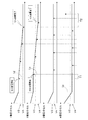
図3の制御を行う場合、図4のようなシーケンスで各セルの充電又は放電がなされる。図4の例では、図3の制御の実行に応じて車載用蓄電部20の充電が開始した後、各セルが次第に充電される。そして、車載用蓄電部20の出力電圧を充電目標電圧に近づける制御を行いつつ、図3の制御によってセル電圧の均等化制御がなされる。このような均等化制御において、各セル電圧の測定は、例えば、時間T1の間隔で行われる。図4のシーケンスでは、車載用蓄電部20の充電が進んだ後の第1の時間taで1番目のセル21のセル電圧が第1閾値V1を超えているため、検査時点taから1番目のセル21に対して個別に放電制御がなされる。この放電制御は、1番目のセル21のセル電圧が第2閾値V2以下になるまで実行される。更に、第2の時間tbで2番目のセル22のセル電圧が第1閾値V1を超えているため、検査時点tbから2番目のセル22に対して個別に放電制御がなされる。この放電制御は、2番目のセル22のセル電圧が第2閾値V2以下になるまで実行される。このようにセル電圧の均等化制御がなされる間は車載用蓄電部20の出力電圧を充電目標電圧とするように充放電回路部30及び制御部62によって充電制御がなされ、全セルが放電状態でない状態が所定の基準時間T2だけ継続した場合に、図3で示すセル電圧の均等化制御を終了する。
When the control shown in FIG. 3 is performed, each cell is charged or discharged in the sequence shown in FIG. In the example of FIG. 4, after charging of the vehicle-mounted
次に、均等化制御の別例として、車載用蓄電部20の放電時の均等化制御について図5、図6などを参照しつつ説明する。
Next, as another example of equalization control, equalization control at the time of discharging of the in-vehicle
制御部62は、所定の放電条件の成立時に、図5のような流れで放電時制御を行うようになっている。なお、所定の放電条件は特に限定されず、例えば、「車両の始動スイッチ(イグニッションスイッチなど)がオン状態からオフ状態に切り替わること」などであってもよい。
When a predetermined discharge condition is satisfied, the
制御部62は、図5の制御を開始した後、まず、車載用蓄電部20を放電するように放電回路部36(図2)に放電動作を行わせる(ステップS31)。具体的には、車載用蓄電部20から放電電流を流すように放電回路部36(図2)に対し放電動作を行わせ、車載用蓄電部20の出力電圧が予め定められた所望の放電目標電圧となるように放電を制御する。制御部62は、このような放電制御を開始した後、ステップS32において、放電目標電圧に到達したか否かを判断する。ステップS32において、車載用蓄電部20の出力電圧が放電目標電圧以下になったと判断した場合(ステップS32でYesの場合)、ステップS33に進み、そうでない場合には、ステップS31の放電動作を継続するとともにステップS32の判断を繰り返す。
After starting the control of FIG. 5, the
制御部62は、ステップS32において、車載用蓄電部20の出力電圧が放電目標電圧以下になったと判断した場合、セルを特定する変数nを1に初期化する(ステップS33)。次に、n番目のセルのセル電圧を検出する(ステップS34)。例えば、nが1に設定されている場合、セル21のセル電圧を電圧検出部40によって検出する。次に、ステップS34で検出したセル電圧が設定部64に設定された第1閾値以上であるか否か判断する(ステップS35)。セル電圧が設定部64で設定された第1閾値以上ではないと判断する場合(ステップS35でNo)、ステップS37の処理に進む。なお、図5、図6等で示す放電時制御の例では、第1閾値については、例えば、V3とし、第2閾値については、例えば、V4とする。
When the
制御部62は、ステップS35において、セル電圧が設定部64で設定された第1閾値以上であると判断する場合(ステップS35でYes)、n番目のセルを個別放電部51,52,53,54のうち対応する個別放電部によって放電する(ステップS36)。例えば、セル21が設定部64で設定された第1閾値以上であると判断する場合、セル21に接続された個別放電部51によって放電する。ステップS36の処理の後、ステップS37に進む。
When the
制御部62は、ステップS35においてセル電圧が設定部64で設定された第1閾値以上でないと判断する場合、又はステップS36の処理の後、n番目のセルが放電処理中であるか否かを判断し、放電処理中であると判断した場合(ステップS37でYesの場合)、ステップS38においてn番目のセルのセル電圧が第2閾値以下であるか否かを判断する。ステップS38において、n番目のセルのセル電圧が第2閾値以下であると判断した場合、ステップS39に進み、n番目のセルの放電を終了する。ステップS38において、n番目のセルのセル電圧が第2閾値以下でないと判断した場合、n番目のセルの放電を終了せずにステップS40に進む。
The
ステップS40では、ステップS40の実行時における変数nが、車載用蓄電部20を構成するセルの数Nよりも小さいか否か判断する。変数nが、セルの数Nよりも小さいと判断する場合(ステップS40でNo)、ステップS41において変数nをn+1に変更し、再びステップS34以降の処理を行う。例えば、S41の処理を行う前に、変数nが1である場合には、ステップS41でnの値を2に変更し、2番目のセルであるセル22に対してステップS34以降の処理を行う。
In step S40, it is determined whether or not the variable n at the time of executing step S40 is smaller than the number N of cells constituting the vehicle-mounted
一方、制御部62は、ステップS40において、変数nが車載用蓄電部20を構成するセルの数Nよりも小さくないと判断した場合、S42の処理に進む。例えば、車載用蓄電部20を構成するセルが4つであり、S40の処理を行う前に、変数nが4である場合には、変数nがセルの数Nよりも小さくないと判断する。制御部62は、ステップS42において、車載用蓄電部20を構成する全てのセルの均等化制御が終了したか否か判断する。具体的には、例えば、全てのセルが放電状態でない状態が所定の基準時間T2継続した場合に、全てのセルの均等化制御が終了したと判断し、図5の制御を終了する。
On the other hand, when the
図5の制御を行う場合、図6のようなシーケンスで各セルの充電又は放電がなされる。図6の例では、図5の制御の実行に応じて車載用蓄電部20の放電が開始した後、各セルが次第に放電される。そして、車載用蓄電部20の出力が放電目標電圧に達した後(図6の例では時間tcの後)、放電回路部36による放電は停止する。その後、図5の制御によってセル電圧の均等化制御がなされる。このような均等化制御において、各セル電圧の測定は、例えば、時間T1の間隔で行われる。図6のシーケンスでは、検査時間tdで1番目のセル21のセル電圧が第1閾値V3を超えているため、検査時点tdから1番目のセル21に対して個別に放電制御がなされる。この放電制御は、1番目のセル21のセル電圧が第2閾値V4以下になるまで実行される。更に、時間teで2番目のセル22のセル電圧が第1閾値を超えているため、検査時点teから2番目のセル22に対して個別に放電制御がなされる。この放電制御は、2番目のセル22のセル電圧が第2閾値V4以下になるまで実行される。このようにセル電圧の均等化制御がなされ、全セルが放電状態でない状態が所定の基準時間T2だけ継続した場合に、図5、図6で示すセル電圧の均等化制御を終了する。
When the control shown in FIG. 5 is performed, each cell is charged or discharged in the sequence shown in FIG. In the example of FIG. 6, after the discharge of the vehicle-mounted
次に、本構成の効果を例示する。
図1等で示す均等化制御装置10は、車載用蓄電部20を構成する複数のセル21,22,23,24の中に、セル電圧が閾値よりも大きい放電対象セルが存在する場合に、この放電対象セルを選択的に放電させ、セル電圧の均等化を図ることができる。しかも、複数のセル21,22,23,24のセル電圧を均等化する際に基準となる閾値は、設定部64によって更新可能に設定されるため、事後的に閾値を調整することが可能となる。
Next, the effect of this configuration will be illustrated.
The
制御部62は、個別放電部51,52,53,54に放電対象セルの放電を開始させた後、放電対象セルの放電中に放電対象セルのセル電圧を閾値よりも小さい第2閾値と比較し、放電対象セルのセル電圧が第2閾値に達した場合に放電対象セルの放電を停止させるように制御を行う。この均等化制御装置10は、放電対象セルの放電開始後、この放電対象セルのセル電圧が第2閾値に達した場合に放電動作を確実に停止することができ、放電対象セルのセル電圧を第2閾値に近い値に高精度に合わせることができる。
The
均等化制御装置10は、車載用蓄電部20を充電する充電回路部34と、充電回路部34からの出力電流を検出する電流検出部70とを有する。制御部62は、車載用蓄電部20の出力電圧が充電目標電圧となるように充電回路部34の充電動作を制御し、充電動作の制御中に電流検出部70によって検出される電流が所定値以下となった後、各々のセル21,22,23,24のセル電圧を閾値とを比較し、放電対象セルが検出された場合に、個別放電部51,52,53,54に当該放電対象セルの放電を行わせる。この均等化制御装置10は、車載用蓄電部20の出力電圧を充電目標電圧に近づけるように充電することができ、車載用蓄電部20の出力電圧を充電目標電圧に近づける制御がなされた状況下で、車載用蓄電部20を構成する全てのセル21,22,23,24が閾値以下となるように均等化させることができる。
The
均等化制御装置10は、車載用蓄電部20を放電させる放電回路部36を備え、制御部62は、車載用蓄電部20の出力電圧が放電目標電圧となるように放電回路部36を制御し、車載用蓄電部20の出力電圧が放電目標電圧に達した後、放電回路部36の放電動作を停止させ、停止後に、各々のセル21,22,23,24のセル電圧を閾値とを比較し、放電対象セルが検出された場合に、個別放電部51,52,53,54に当該放電対象セルの放電を行わせる。この均等化制御装置10は、車載用蓄電部20の出力電圧が所望の放電目標電圧となるように放電回路部36によって放電することができる。そして、このように車載用蓄電部20の出力電圧を放電目標電圧に近づけた上で、車載用蓄電部20を構成する全てのセル21,22,23,24が閾値以下となるように均等化させることができる。
The
均等化制御装置10は、車載用蓄電部20の温度を検出する温度検出部80を備え、設定部64は、温度検出部80によって検出された温度が高くなるほど閾値(第1閾値)を小さくするように設定する。具体的には、温度が高くなるほど閾値(第1閾値)を小さくするように温度と閾値(第1閾値)を対応付けたテーブルや演算式などを用いることができ、制御部62は、所定のタイミングで温度検出部80で検出された温度を把握するとともに、上記テーブル又は演算式を参照して検出された温度に対応付けられた閾値(第1閾値)を特定し、この閾値(第1閾値)となるように設定部64で設定される閾値(第1閾値)を更新すればよい。なお、所定のタイミングは、例えば、車両の始動スイッチの切り替わりのタイミング(オフからオンに切り替わるタイミング、又はオンからオフに切り替わるタイミング)などであってもよく、これ以外のタイミングであってもよい。
The
このように構成された均等化制御装置10は、均等化する際に基準とする閾値(第1閾値)を温度に合わせて事後的に適正化することができる。
The
また、第1閾値と同様に、第2閾値についても温度に応じた値に設定してもよい。具体的には、温度検出部80によって検出された温度が高くなるほど第2閾値を小さくするように且つ第1閾値よりも第2閾値のほうが小さくなるように温度と第2閾値を対応付けたテーブルや演算式などを用いることができ、制御部62は、所定のタイミングにて温度検出部80で検出された温度を把握するとともに、上記テーブル又は演算式を参照して検出された温度に対応付けられた第2閾値を特定し、この第2閾値となるように設定部64で設定される第2閾値を更新すればよい。
Further, similarly to the first threshold value, the second threshold value may be set to a value according to the temperature. Specifically, a table in which the temperature and the second threshold value are associated so that the second threshold value becomes smaller as the temperature detected by the
<他の実施例>
本発明は上記記述及び図面によって説明した実施例1に限定されるものではなく、例えば次のような実施例も本発明の技術的範囲に含まれる。
<Other Examples>
The present invention is not limited to the first embodiment described by the above description and the drawings, and for example, the following examples are also included in the technical scope of the present invention.
実施例1では、制御部62は、個別放電部に放電対象セルの放電を開始させた後、その放電対象セルのセル電圧が第2閾値に達した場合に放電を終了する例を示したが、この例に限定されない。制御部62は、個別放電部に放電対象セルの放電を開始させた後、所定時間が経過した場合、個別放電部による放電対象セルの放電を停止させる構成であってもよい。つまり、第2閾値に基づく放電停止に代えて、放電開始からの時間経過に基づいて放電を停止させてもよい。この均等化制御装置10は、セル電圧が閾値よりも大きい放電対象セルを放電させる場合に、所定時間の放電で低下する程度に合わせることができる。
In the first embodiment, the
実施例1では、車載用蓄電部20の放電時の均等化制御において、放電回路部36によって車載用蓄電部20の放電動作(S31)を行う構成を例示したが、個別放電部51〜54によって車載用蓄電部20の放電動作を行う構成であってもよい。すなわち、個別放電部51〜54によってそれぞれセル21〜24を放電させる構成であってもよい。
In the first embodiment, the configuration in which the
1…車載用電源装置
10…均等化制御装置
20…車載用蓄電部
21,22,23,24…セル
34…充電回路部
36…放電回路部
40…電圧検出部
51,52,53,544…個別放電部
62…制御部
64…設定部
70…電流検出部
80…温度検出部
1 ... Vehicle
Claims (3)
各々の前記セルのセル電圧を個別に検出する電圧検出部と、
各々の前記セルを個別に放電させる個別放電部と、
前記電圧検出部で検出されたセル電圧と比較する基準値となる第1閾値を、更新可能に設定する設定部と、
前記車載用蓄電部を充電する充電回路部と、
前記充電回路部からの出力電流を検出する電流検出部と、
前記個別放電部を制御する制御部と、
前記車載用蓄電部の温度を検出する温度検出部と、
を備え、
前記制御部は、
前記車載用蓄電部の出力電圧が充電目標電圧となるように前記充電回路部の充電動作を制御し、
前記充電動作の制御中に前記電流検出部によって検出される電流が所定値以下となった後、前記充電回路部の前記充電動作を継続しつつ、前記電圧検出部で検出された各々の前記セルのセル電圧と前記設定部で設定された前記第1閾値とを比較し且つ複数の前記セルの中でセル電圧が前記第1閾値よりも大きい放電対象セルを選択的に放電させるように前記個別放電部の制御を行い、
前記充電回路部の前記充電動作を継続しつつ、前記放電対象セルの放電中に前記放電対象セルのセル電圧を前記第1閾値よりも小さい第2閾値と比較し、前記放電対象セルのセル電圧が前記第2閾値に達した場合に、前記個別放電部に前記放電対象セルの放電を停止させ、
いずれかの前記放電対象セルの放電が開始した後、全ての前記セルにおいて放電が行われなくなった場合に前記充電回路部の充電動作を終了し、
前記設定部は、前記温度検出部によって検出された温度が高くなるほど前記第1閾値及び前記第2閾値を小さくするように、かつ前記第1閾値よりも前記第2閾値の方が小さくなるように設定する均等化制御装置。 An equalization control device that equalizes the cell voltage of an in-vehicle power storage unit having a plurality of cells.
A voltage detector that individually detects the cell voltage of each cell,
An individual discharge unit that discharges each of the cells individually,
A setting unit that sets the first threshold value, which is a reference value to be compared with the cell voltage detected by the voltage detection unit, so that it can be updated.
A charging circuit unit for charging the in-vehicle power storage unit and
A current detection unit that detects the output current from the charging circuit unit, and
A control unit that controls the individual discharge unit and
A temperature detection unit that detects the temperature of the vehicle-mounted power storage unit, and
With
The control unit
The charging operation of the charging circuit unit is controlled so that the output voltage of the vehicle-mounted power storage unit becomes the charging target voltage.
After the current detected by the current detection unit becomes a predetermined value or less during the control of the charging operation, each of the cells detected by the voltage detecting unit continues the charging operation of the charging circuit unit. The individual cell voltage is compared with the first threshold value set by the setting unit, and the individual discharge target cells whose cell voltage is larger than the first threshold value among the plurality of cells are selectively discharged. and it controls the discharge unit,
While continuing the charging operation of the charging circuit unit, the cell voltage of the discharge target cell is compared with a second threshold value smaller than the first threshold value while the discharge target cell is being discharged, and the cell voltage of the discharge target cell is compared. When the second threshold value is reached, the individual discharge unit is allowed to stop the discharge of the discharge target cell.
After the discharge of any of the discharge target cells is started, when the discharge is not performed in all the cells, the charging operation of the charging circuit unit is terminated.
The setting unit reduces the first threshold value and the second threshold value as the temperature detected by the temperature detection unit increases, and the second threshold value becomes smaller than the first threshold value. Equalization control device to set.
前記制御部は、前記車載用蓄電部の出力電圧が放電目標電圧となるように前記放電回路部を制御し、前記車載用蓄電部の出力電圧が前記放電目標電圧に達した後、前記放電回路部の放電動作を停止させ、停止後に、各々の前記セルのセル電圧を前記第1閾値とを比較し、前記放電対象セルが検出された場合に、前記個別放電部に当該放電対象セルの放電を行わせる請求項1に記載の均等化制御装置。 A discharge circuit unit for discharging the in-vehicle power storage unit is provided.
The control unit controls the discharge circuit unit so that the output voltage of the vehicle-mounted power storage unit becomes the discharge target voltage, and after the output voltage of the vehicle-mounted power storage unit reaches the discharge target voltage, the discharge circuit The discharge operation of the unit is stopped, and after the stop, the cell voltage of each of the cells is compared with the first threshold value, and when the discharge target cell is detected, the discharge target cell is discharged to the individual discharge unit. The equalization control device according to claim 1.
Priority Applications (4)
| Application Number | Priority Date | Filing Date | Title |
|---|---|---|---|
| JP2017020191A JP6855822B2 (en) | 2017-02-07 | 2017-02-07 | Equalization control device and in-vehicle power supply device |
| CN201880007668.5A CN110235334B (en) | 2017-02-07 | 2018-01-26 | Equalization control device and vehicle-mounted power supply device |
| PCT/JP2018/002419 WO2018147091A1 (en) | 2017-02-07 | 2018-01-26 | Balancing control device and in-vehicle power supply device |
| US16/484,266 US11110817B2 (en) | 2017-02-07 | 2018-01-26 | Equalization control device and in-vehicle power supply device |
Applications Claiming Priority (1)
| Application Number | Priority Date | Filing Date | Title |
|---|---|---|---|
| JP2017020191A JP6855822B2 (en) | 2017-02-07 | 2017-02-07 | Equalization control device and in-vehicle power supply device |
Publications (3)
| Publication Number | Publication Date |
|---|---|
| JP2018129902A JP2018129902A (en) | 2018-08-16 |
| JP2018129902A5 JP2018129902A5 (en) | 2019-07-11 |
| JP6855822B2 true JP6855822B2 (en) | 2021-04-07 |
Family
ID=63108180
Family Applications (1)
| Application Number | Title | Priority Date | Filing Date |
|---|---|---|---|
| JP2017020191A Active JP6855822B2 (en) | 2017-02-07 | 2017-02-07 | Equalization control device and in-vehicle power supply device |
Country Status (4)
| Country | Link |
|---|---|
| US (1) | US11110817B2 (en) |
| JP (1) | JP6855822B2 (en) |
| CN (1) | CN110235334B (en) |
| WO (1) | WO2018147091A1 (en) |
Families Citing this family (3)
| Publication number | Priority date | Publication date | Assignee | Title |
|---|---|---|---|---|
| CN111527664B (en) * | 2018-03-01 | 2023-06-30 | 株式会社村田制作所 | Battery pack |
| JP7481147B2 (en) | 2020-03-31 | 2024-05-10 | Fdk株式会社 | Battery voltage equalizer |
| CN117183818A (en) * | 2022-05-30 | 2023-12-08 | 比亚迪半导体股份有限公司 | Battery management chip, battery system and vehicle |
Family Cites Families (20)
| Publication number | Priority date | Publication date | Assignee | Title |
|---|---|---|---|---|
| CA2169706A1 (en) * | 1995-03-03 | 1996-09-04 | Troy Lynn Stockstad | Circuit and method for battery charge control |
| JPH0923590A (en) * | 1995-07-07 | 1997-01-21 | Sony Corp | Charging apparatus |
| JP2000197279A (en) * | 1998-12-28 | 2000-07-14 | Asahi Glass Co Ltd | Power supply unit with built-in electric double-layer capacitor |
| JP2001025162A (en) | 1999-07-08 | 2001-01-26 | Ngk Insulators Ltd | Uniformly charging equipment for electric double-layer capacitor |
| JP4605952B2 (en) * | 2001-08-29 | 2011-01-05 | 株式会社日立製作所 | Power storage device and control method thereof |
| US6700350B2 (en) | 2002-05-30 | 2004-03-02 | Texas Instruments Incorporated | Method and apparatus for controlling charge balance among cells while charging a battery array |
| JP5002919B2 (en) * | 2005-07-07 | 2012-08-15 | 日産自動車株式会社 | Voltage variation control device |
| JP4738121B2 (en) * | 2005-09-30 | 2011-08-03 | 三洋電機株式会社 | Electronic device cooling device and electronic device |
| KR100839382B1 (en) * | 2006-10-16 | 2008-06-20 | 삼성에스디아이 주식회사 | Battery management system and driving method thereof |
| JP5091473B2 (en) * | 2006-12-14 | 2012-12-05 | パナソニック株式会社 | Battery pack control method, battery pack control circuit, charging circuit including the battery pack, and battery pack |
| WO2011052594A1 (en) * | 2009-10-27 | 2011-05-05 | ミツミ電機株式会社 | Charge/discharge control circuit, semiconductor integrated circuit, charge/discharge control method, and charge/discharge control program |
| JP5624907B2 (en) * | 2011-02-17 | 2014-11-12 | 本田技研工業株式会社 | Power storage device, disconnection detection device, vehicle, and disconnection detection method |
| CN102790407B (en) * | 2011-05-16 | 2015-08-19 | 上海汽车集团股份有限公司 | Charge/discharge control method in two storage battery car electric power system |
| JP5644691B2 (en) * | 2011-06-21 | 2014-12-24 | 株式会社豊田自動織機 | Cell balance control device and cell balance control method |
| CA2746304A1 (en) * | 2011-07-15 | 2013-01-15 | Hydro-Quebec | Multi-level rapid charge system with nested power batteries |
| JP5811874B2 (en) * | 2012-02-02 | 2015-11-11 | ミツミ電機株式会社 | Battery protection circuit, battery protection device, and battery pack |
| JP6196466B2 (en) * | 2013-05-10 | 2017-09-13 | Fdk株式会社 | Power supply |
| JP6266248B2 (en) * | 2013-07-19 | 2018-01-24 | サイプレス セミコンダクター コーポレーション | Semiconductor device, discharge control system, and control method |
| JP2016034221A (en) | 2014-07-31 | 2016-03-10 | 株式会社東芝 | Battery monitoring device, storage battery module, storage battery unit |
| CN204258377U (en) * | 2014-12-11 | 2015-04-08 | 深圳市云兔能源科技有限公司 | A kind of lithium battery group intelligent balance recovers charger |
-
2017
- 2017-02-07 JP JP2017020191A patent/JP6855822B2/en active Active
-
2018
- 2018-01-26 US US16/484,266 patent/US11110817B2/en active Active
- 2018-01-26 WO PCT/JP2018/002419 patent/WO2018147091A1/en active Application Filing
- 2018-01-26 CN CN201880007668.5A patent/CN110235334B/en active Active
Also Published As
| Publication number | Publication date |
|---|---|
| WO2018147091A1 (en) | 2018-08-16 |
| CN110235334A (en) | 2019-09-13 |
| CN110235334B (en) | 2023-05-23 |
| JP2018129902A (en) | 2018-08-16 |
| US11110817B2 (en) | 2021-09-07 |
| US20200001740A1 (en) | 2020-01-02 |
Similar Documents
| Publication | Publication Date | Title |
|---|---|---|
| KR102150147B1 (en) | Apparatus and method for balancing battery module | |
| CN106941270B (en) | Battery control apparatus and battery control system | |
| EP2418751B1 (en) | Battery charger and battery charging method | |
| JP6627635B2 (en) | Voltage measurement device and voltage measurement method, and voltage control device and voltage control method | |
| US10211490B2 (en) | Storage battery deterioration measurement device and power storage system | |
| JP5126403B1 (en) | Charge / discharge control device | |
| JP6855822B2 (en) | Equalization control device and in-vehicle power supply device | |
| JP6415218B2 (en) | Storage system and storage system precharge method | |
| WO2018180333A1 (en) | Control device for onboard power supply system, and onboard power supply system | |
| KR20190000142A (en) | Battery cell balancing circuit and apparatus and method for balancing of a battery cell for using the same | |
| JP2008182809A (en) | Battery circuit, battery pack, and battery system | |
| US20130207610A1 (en) | Balancing cells in a battery pack | |
| JP6136820B2 (en) | Battery monitoring device, power storage device, and battery monitoring method | |
| JP6307992B2 (en) | Power supply | |
| JP5332062B2 (en) | Uninterruptible power supply system and battery charging method | |
| JP6387940B2 (en) | In-vehicle power supply | |
| KR20190048526A (en) | Cell balancing apparatus and method | |
| KR102347920B1 (en) | Apparatus and method for battery management | |
| WO2014141989A1 (en) | Voltage equalizer and voltage equalization method | |
| JP2010246214A (en) | Device for regulating and monitoring battery voltage | |
| JP2017219430A (en) | Battery system | |
| JP2021090318A (en) | Battery pack, control method, and program | |
| KR20210073336A (en) | Apparatus and method for managing battery | |
| JP7276200B2 (en) | battery monitor | |
| US9443684B2 (en) | Charging and discharging control apparatus of DC link capacitor in electric power steering relay and method thereof |
Legal Events
| Date | Code | Title | Description |
|---|---|---|---|
| A621 | Written request for application examination |
Free format text: JAPANESE INTERMEDIATE CODE: A621 Effective date: 20190530 |
|
| A521 | Request for written amendment filed |
Free format text: JAPANESE INTERMEDIATE CODE: A523 Effective date: 20190604 |
|
| A131 | Notification of reasons for refusal |
Free format text: JAPANESE INTERMEDIATE CODE: A131 Effective date: 20200709 |
|
| A521 | Request for written amendment filed |
Free format text: JAPANESE INTERMEDIATE CODE: A523 Effective date: 20200907 |
|
| TRDD | Decision of grant or rejection written | ||
| A01 | Written decision to grant a patent or to grant a registration (utility model) |
Free format text: JAPANESE INTERMEDIATE CODE: A01 Effective date: 20210216 |
|
| A61 | First payment of annual fees (during grant procedure) |
Free format text: JAPANESE INTERMEDIATE CODE: A61 Effective date: 20210301 |
|
| R150 | Certificate of patent or registration of utility model |
Ref document number: 6855822 Country of ref document: JP Free format text: JAPANESE INTERMEDIATE CODE: R150 |