JP6793751B2 - Metal plate sandwiching a hollow tube and its uses - Google Patents
Metal plate sandwiching a hollow tube and its uses Download PDFInfo
- Publication number
- JP6793751B2 JP6793751B2 JP2018552113A JP2018552113A JP6793751B2 JP 6793751 B2 JP6793751 B2 JP 6793751B2 JP 2018552113 A JP2018552113 A JP 2018552113A JP 2018552113 A JP2018552113 A JP 2018552113A JP 6793751 B2 JP6793751 B2 JP 6793751B2
- Authority
- JP
- Japan
- Prior art keywords
- hollow tube
- panel
- hollow
- metal plate
- metal
- Prior art date
- Legal status (The legal status is an assumption and is not a legal conclusion. Google has not performed a legal analysis and makes no representation as to the accuracy of the status listed.)
- Active
Links
- 229910052751 metal Inorganic materials 0.000 title claims description 120
- 239000002184 metal Substances 0.000 title claims description 120
- 238000005219 brazing Methods 0.000 claims description 45
- 239000000463 material Substances 0.000 claims description 23
- 229910001220 stainless steel Inorganic materials 0.000 claims description 9
- 239000010935 stainless steel Substances 0.000 claims description 8
- RYGMFSIKBFXOCR-UHFFFAOYSA-N Copper Chemical compound [Cu] RYGMFSIKBFXOCR-UHFFFAOYSA-N 0.000 claims description 7
- 239000010949 copper Substances 0.000 claims description 7
- 229910052802 copper Inorganic materials 0.000 claims description 7
- 239000011810 insulating material Substances 0.000 claims description 6
- 230000000149 penetrating effect Effects 0.000 claims description 6
- 238000009423 ventilation Methods 0.000 claims description 6
- 229910000975 Carbon steel Inorganic materials 0.000 claims description 4
- 229910000881 Cu alloy Inorganic materials 0.000 claims description 4
- RTAQQCXQSZGOHL-UHFFFAOYSA-N Titanium Chemical compound [Ti] RTAQQCXQSZGOHL-UHFFFAOYSA-N 0.000 claims description 4
- 239000010962 carbon steel Substances 0.000 claims description 4
- 239000010936 titanium Substances 0.000 claims description 4
- 229910052719 titanium Inorganic materials 0.000 claims description 4
- ATJFFYVFTNAWJD-UHFFFAOYSA-N Tin Chemical compound [Sn] ATJFFYVFTNAWJD-UHFFFAOYSA-N 0.000 claims description 2
- 229910045601 alloy Inorganic materials 0.000 claims description 2
- 239000000956 alloy Substances 0.000 claims description 2
- 229910052782 aluminium Inorganic materials 0.000 claims description 2
- XAGFODPZIPBFFR-UHFFFAOYSA-N aluminium Chemical compound [Al] XAGFODPZIPBFFR-UHFFFAOYSA-N 0.000 claims description 2
- 229910052718 tin Inorganic materials 0.000 claims description 2
- 238000004804 winding Methods 0.000 claims 1
- 239000007789 gas Substances 0.000 description 38
- 239000001993 wax Substances 0.000 description 33
- 238000010586 diagram Methods 0.000 description 29
- 238000003466 welding Methods 0.000 description 19
- 238000000034 method Methods 0.000 description 18
- 238000005192 partition Methods 0.000 description 17
- 238000010438 heat treatment Methods 0.000 description 9
- 238000012986 modification Methods 0.000 description 6
- 230000004048 modification Effects 0.000 description 6
- 239000006260 foam Substances 0.000 description 5
- 238000009413 insulation Methods 0.000 description 4
- 238000005304 joining Methods 0.000 description 4
- 230000003014 reinforcing effect Effects 0.000 description 4
- 239000011550 stock solution Substances 0.000 description 4
- 229920000742 Cotton Polymers 0.000 description 3
- 239000002131 composite material Substances 0.000 description 3
- 238000001816 cooling Methods 0.000 description 3
- 238000005520 cutting process Methods 0.000 description 3
- 230000000694 effects Effects 0.000 description 3
- 238000005187 foaming Methods 0.000 description 3
- 238000002844 melting Methods 0.000 description 3
- 230000008018 melting Effects 0.000 description 3
- 239000011435 rock Substances 0.000 description 3
- 238000003860 storage Methods 0.000 description 3
- 230000035882 stress Effects 0.000 description 3
- IJGRMHOSHXDMSA-UHFFFAOYSA-N Atomic nitrogen Chemical compound N#N IJGRMHOSHXDMSA-UHFFFAOYSA-N 0.000 description 2
- UFHFLCQGNIYNRP-UHFFFAOYSA-N Hydrogen Chemical compound [H][H] UFHFLCQGNIYNRP-UHFFFAOYSA-N 0.000 description 2
- 239000010953 base metal Substances 0.000 description 2
- 238000005452 bending Methods 0.000 description 2
- 230000007547 defect Effects 0.000 description 2
- 229910001873 dinitrogen Inorganic materials 0.000 description 2
- 238000002955 isolation Methods 0.000 description 2
- 239000003973 paint Substances 0.000 description 2
- 229920002635 polyurethane Polymers 0.000 description 2
- 239000004814 polyurethane Substances 0.000 description 2
- 239000011178 precast concrete Substances 0.000 description 2
- MYMOFIZGZYHOMD-UHFFFAOYSA-N Dioxygen Chemical compound O=O MYMOFIZGZYHOMD-UHFFFAOYSA-N 0.000 description 1
- 241000220317 Rosa Species 0.000 description 1
- 239000000853 adhesive Substances 0.000 description 1
- 230000001070 adhesive effect Effects 0.000 description 1
- 230000032683 aging Effects 0.000 description 1
- 238000006243 chemical reaction Methods 0.000 description 1
- 238000010276 construction Methods 0.000 description 1
- 230000007812 deficiency Effects 0.000 description 1
- 230000008021 deposition Effects 0.000 description 1
- 229910001882 dioxygen Inorganic materials 0.000 description 1
- 238000007599 discharging Methods 0.000 description 1
- 238000006073 displacement reaction Methods 0.000 description 1
- 238000005516 engineering process Methods 0.000 description 1
- 230000007613 environmental effect Effects 0.000 description 1
- 239000006261 foam material Substances 0.000 description 1
- 239000001307 helium Substances 0.000 description 1
- 229910052734 helium Inorganic materials 0.000 description 1
- SWQJXJOGLNCZEY-UHFFFAOYSA-N helium atom Chemical compound [He] SWQJXJOGLNCZEY-UHFFFAOYSA-N 0.000 description 1
- 239000010954 inorganic particle Substances 0.000 description 1
- 230000001788 irregular Effects 0.000 description 1
- 239000010985 leather Substances 0.000 description 1
- 239000007788 liquid Substances 0.000 description 1
- 238000004519 manufacturing process Methods 0.000 description 1
- 239000007769 metal material Substances 0.000 description 1
- 239000002245 particle Substances 0.000 description 1
- 239000005011 phenolic resin Substances 0.000 description 1
- 238000004080 punching Methods 0.000 description 1
- 230000002787 reinforcement Effects 0.000 description 1
- 238000004904 shortening Methods 0.000 description 1
- 230000007847 structural defect Effects 0.000 description 1
- 239000002023 wood Substances 0.000 description 1
Images


Classifications
-
- E—FIXED CONSTRUCTIONS
- E04—BUILDING
- E04C—STRUCTURAL ELEMENTS; BUILDING MATERIALS
- E04C2/00—Building elements of relatively thin form for the construction of parts of buildings, e.g. sheet materials, slabs, or panels
- E04C2/30—Building elements of relatively thin form for the construction of parts of buildings, e.g. sheet materials, slabs, or panels characterised by the shape or structure
- E04C2/32—Building elements of relatively thin form for the construction of parts of buildings, e.g. sheet materials, slabs, or panels characterised by the shape or structure formed of corrugated or otherwise indented sheet-like material; composed of such layers with or without layers of flat sheet-like material
-
- B—PERFORMING OPERATIONS; TRANSPORTING
- B23—MACHINE TOOLS; METAL-WORKING NOT OTHERWISE PROVIDED FOR
- B23K—SOLDERING OR UNSOLDERING; WELDING; CLADDING OR PLATING BY SOLDERING OR WELDING; CUTTING BY APPLYING HEAT LOCALLY, e.g. FLAME CUTTING; WORKING BY LASER BEAM
- B23K1/00—Soldering, e.g. brazing, or unsoldering
- B23K1/0008—Soldering, e.g. brazing, or unsoldering specially adapted for particular articles or work
- B23K1/0014—Brazing of honeycomb sandwich structures
-
- B—PERFORMING OPERATIONS; TRANSPORTING
- B23—MACHINE TOOLS; METAL-WORKING NOT OTHERWISE PROVIDED FOR
- B23K—SOLDERING OR UNSOLDERING; WELDING; CLADDING OR PLATING BY SOLDERING OR WELDING; CUTTING BY APPLYING HEAT LOCALLY, e.g. FLAME CUTTING; WORKING BY LASER BEAM
- B23K1/00—Soldering, e.g. brazing, or unsoldering
- B23K1/012—Soldering with the use of hot gas
-
- B—PERFORMING OPERATIONS; TRANSPORTING
- B23—MACHINE TOOLS; METAL-WORKING NOT OTHERWISE PROVIDED FOR
- B23K—SOLDERING OR UNSOLDERING; WELDING; CLADDING OR PLATING BY SOLDERING OR WELDING; CUTTING BY APPLYING HEAT LOCALLY, e.g. FLAME CUTTING; WORKING BY LASER BEAM
- B23K35/00—Rods, electrodes, materials, or media, for use in soldering, welding, or cutting
- B23K35/02—Rods, electrodes, materials, or media, for use in soldering, welding, or cutting characterised by mechanical features, e.g. shape
- B23K35/0222—Rods, electrodes, materials, or media, for use in soldering, welding, or cutting characterised by mechanical features, e.g. shape for use in soldering, brazing
-
- B—PERFORMING OPERATIONS; TRANSPORTING
- B23—MACHINE TOOLS; METAL-WORKING NOT OTHERWISE PROVIDED FOR
- B23K—SOLDERING OR UNSOLDERING; WELDING; CLADDING OR PLATING BY SOLDERING OR WELDING; CUTTING BY APPLYING HEAT LOCALLY, e.g. FLAME CUTTING; WORKING BY LASER BEAM
- B23K37/00—Auxiliary devices or processes, not specially adapted to a procedure covered by only one of the preceding main groups
- B23K37/003—Cooling means
-
- B—PERFORMING OPERATIONS; TRANSPORTING
- B23—MACHINE TOOLS; METAL-WORKING NOT OTHERWISE PROVIDED FOR
- B23P—METAL-WORKING NOT OTHERWISE PROVIDED FOR; COMBINED OPERATIONS; UNIVERSAL MACHINE TOOLS
- B23P15/00—Making specific metal objects by operations not covered by a single other subclass or a group in this subclass
-
- B—PERFORMING OPERATIONS; TRANSPORTING
- B29—WORKING OF PLASTICS; WORKING OF SUBSTANCES IN A PLASTIC STATE IN GENERAL
- B29C—SHAPING OR JOINING OF PLASTICS; SHAPING OF MATERIAL IN A PLASTIC STATE, NOT OTHERWISE PROVIDED FOR; AFTER-TREATMENT OF THE SHAPED PRODUCTS, e.g. REPAIRING
- B29C44/00—Shaping by internal pressure generated in the material, e.g. swelling or foaming ; Producing porous or cellular expanded plastics articles
- B29C44/02—Shaping by internal pressure generated in the material, e.g. swelling or foaming ; Producing porous or cellular expanded plastics articles for articles of definite length, i.e. discrete articles
- B29C44/12—Incorporating or moulding on preformed parts, e.g. inserts or reinforcements
- B29C44/1214—Anchoring by foaming into a preformed part, e.g. by penetrating through holes
-
- B—PERFORMING OPERATIONS; TRANSPORTING
- B32—LAYERED PRODUCTS
- B32B—LAYERED PRODUCTS, i.e. PRODUCTS BUILT-UP OF STRATA OF FLAT OR NON-FLAT, e.g. CELLULAR OR HONEYCOMB, FORM
- B32B15/00—Layered products comprising a layer of metal
-
- B—PERFORMING OPERATIONS; TRANSPORTING
- B32—LAYERED PRODUCTS
- B32B—LAYERED PRODUCTS, i.e. PRODUCTS BUILT-UP OF STRATA OF FLAT OR NON-FLAT, e.g. CELLULAR OR HONEYCOMB, FORM
- B32B15/00—Layered products comprising a layer of metal
- B32B15/01—Layered products comprising a layer of metal all layers being exclusively metallic
- B32B15/011—Layered products comprising a layer of metal all layers being exclusively metallic all layers being formed of iron alloys or steels
-
- B—PERFORMING OPERATIONS; TRANSPORTING
- B32—LAYERED PRODUCTS
- B32B—LAYERED PRODUCTS, i.e. PRODUCTS BUILT-UP OF STRATA OF FLAT OR NON-FLAT, e.g. CELLULAR OR HONEYCOMB, FORM
- B32B15/00—Layered products comprising a layer of metal
- B32B15/01—Layered products comprising a layer of metal all layers being exclusively metallic
- B32B15/013—Layered products comprising a layer of metal all layers being exclusively metallic one layer being formed of an iron alloy or steel, another layer being formed of a metal other than iron or aluminium
- B32B15/015—Layered products comprising a layer of metal all layers being exclusively metallic one layer being formed of an iron alloy or steel, another layer being formed of a metal other than iron or aluminium the said other metal being copper or nickel or an alloy thereof
-
- B—PERFORMING OPERATIONS; TRANSPORTING
- B32—LAYERED PRODUCTS
- B32B—LAYERED PRODUCTS, i.e. PRODUCTS BUILT-UP OF STRATA OF FLAT OR NON-FLAT, e.g. CELLULAR OR HONEYCOMB, FORM
- B32B15/00—Layered products comprising a layer of metal
- B32B15/04—Layered products comprising a layer of metal comprising metal as the main or only constituent of a layer, which is next to another layer of the same or of a different material
- B32B15/043—Layered products comprising a layer of metal comprising metal as the main or only constituent of a layer, which is next to another layer of the same or of a different material of metal
-
- B—PERFORMING OPERATIONS; TRANSPORTING
- B32—LAYERED PRODUCTS
- B32B—LAYERED PRODUCTS, i.e. PRODUCTS BUILT-UP OF STRATA OF FLAT OR NON-FLAT, e.g. CELLULAR OR HONEYCOMB, FORM
- B32B3/00—Layered products comprising a layer with external or internal discontinuities or unevennesses, or a layer of non-planar shape; Layered products comprising a layer having particular features of form
- B32B3/10—Layered products comprising a layer with external or internal discontinuities or unevennesses, or a layer of non-planar shape; Layered products comprising a layer having particular features of form characterised by a discontinuous layer, i.e. formed of separate pieces of material
- B32B3/12—Layered products comprising a layer with external or internal discontinuities or unevennesses, or a layer of non-planar shape; Layered products comprising a layer having particular features of form characterised by a discontinuous layer, i.e. formed of separate pieces of material characterised by a layer of regularly- arranged cells, e.g. a honeycomb structure
-
- B—PERFORMING OPERATIONS; TRANSPORTING
- B32—LAYERED PRODUCTS
- B32B—LAYERED PRODUCTS, i.e. PRODUCTS BUILT-UP OF STRATA OF FLAT OR NON-FLAT, e.g. CELLULAR OR HONEYCOMB, FORM
- B32B3/00—Layered products comprising a layer with external or internal discontinuities or unevennesses, or a layer of non-planar shape; Layered products comprising a layer having particular features of form
- B32B3/10—Layered products comprising a layer with external or internal discontinuities or unevennesses, or a layer of non-planar shape; Layered products comprising a layer having particular features of form characterised by a discontinuous layer, i.e. formed of separate pieces of material
- B32B3/18—Layered products comprising a layer with external or internal discontinuities or unevennesses, or a layer of non-planar shape; Layered products comprising a layer having particular features of form characterised by a discontinuous layer, i.e. formed of separate pieces of material characterised by an internal layer formed of separate pieces of material which are juxtaposed side-by-side
- B32B3/20—Layered products comprising a layer with external or internal discontinuities or unevennesses, or a layer of non-planar shape; Layered products comprising a layer having particular features of form characterised by a discontinuous layer, i.e. formed of separate pieces of material characterised by an internal layer formed of separate pieces of material which are juxtaposed side-by-side of hollow pieces, e.g. tubes; of pieces with channels or cavities
-
- B—PERFORMING OPERATIONS; TRANSPORTING
- B32—LAYERED PRODUCTS
- B32B—LAYERED PRODUCTS, i.e. PRODUCTS BUILT-UP OF STRATA OF FLAT OR NON-FLAT, e.g. CELLULAR OR HONEYCOMB, FORM
- B32B37/00—Methods or apparatus for laminating, e.g. by curing or by ultrasonic bonding
- B32B37/06—Methods or apparatus for laminating, e.g. by curing or by ultrasonic bonding characterised by the heating method
-
- E—FIXED CONSTRUCTIONS
- E04—BUILDING
- E04C—STRUCTURAL ELEMENTS; BUILDING MATERIALS
- E04C2/00—Building elements of relatively thin form for the construction of parts of buildings, e.g. sheet materials, slabs, or panels
- E04C2/02—Building elements of relatively thin form for the construction of parts of buildings, e.g. sheet materials, slabs, or panels characterised by specified materials
- E04C2/08—Building elements of relatively thin form for the construction of parts of buildings, e.g. sheet materials, slabs, or panels characterised by specified materials of metal, e.g. sheet metal
-
- E—FIXED CONSTRUCTIONS
- E04—BUILDING
- E04C—STRUCTURAL ELEMENTS; BUILDING MATERIALS
- E04C2/00—Building elements of relatively thin form for the construction of parts of buildings, e.g. sheet materials, slabs, or panels
- E04C2/30—Building elements of relatively thin form for the construction of parts of buildings, e.g. sheet materials, slabs, or panels characterised by the shape or structure
- E04C2/34—Building elements of relatively thin form for the construction of parts of buildings, e.g. sheet materials, slabs, or panels characterised by the shape or structure composed of two or more spaced sheet-like parts
- E04C2/36—Building elements of relatively thin form for the construction of parts of buildings, e.g. sheet materials, slabs, or panels characterised by the shape or structure composed of two or more spaced sheet-like parts spaced apart by transversely-placed strip material, e.g. honeycomb panels
- E04C2/365—Building elements of relatively thin form for the construction of parts of buildings, e.g. sheet materials, slabs, or panels characterised by the shape or structure composed of two or more spaced sheet-like parts spaced apart by transversely-placed strip material, e.g. honeycomb panels by honeycomb structures
-
- F—MECHANICAL ENGINEERING; LIGHTING; HEATING; WEAPONS; BLASTING
- F16—ENGINEERING ELEMENTS AND UNITS; GENERAL MEASURES FOR PRODUCING AND MAINTAINING EFFECTIVE FUNCTIONING OF MACHINES OR INSTALLATIONS; THERMAL INSULATION IN GENERAL
- F16L—PIPES; JOINTS OR FITTINGS FOR PIPES; SUPPORTS FOR PIPES, CABLES OR PROTECTIVE TUBING; MEANS FOR THERMAL INSULATION IN GENERAL
- F16L59/00—Thermal insulation in general
-
- B—PERFORMING OPERATIONS; TRANSPORTING
- B23—MACHINE TOOLS; METAL-WORKING NOT OTHERWISE PROVIDED FOR
- B23K—SOLDERING OR UNSOLDERING; WELDING; CLADDING OR PLATING BY SOLDERING OR WELDING; CUTTING BY APPLYING HEAT LOCALLY, e.g. FLAME CUTTING; WORKING BY LASER BEAM
- B23K2101/00—Articles made by soldering, welding or cutting
- B23K2101/04—Tubular or hollow articles
- B23K2101/045—Hollow panels
-
- B—PERFORMING OPERATIONS; TRANSPORTING
- B23—MACHINE TOOLS; METAL-WORKING NOT OTHERWISE PROVIDED FOR
- B23K—SOLDERING OR UNSOLDERING; WELDING; CLADDING OR PLATING BY SOLDERING OR WELDING; CUTTING BY APPLYING HEAT LOCALLY, e.g. FLAME CUTTING; WORKING BY LASER BEAM
- B23K35/00—Rods, electrodes, materials, or media, for use in soldering, welding, or cutting
- B23K35/22—Rods, electrodes, materials, or media, for use in soldering, welding, or cutting characterised by the composition or nature of the material
- B23K35/24—Selection of soldering or welding materials proper
- B23K35/30—Selection of soldering or welding materials proper with the principal constituent melting at less than 1550 degrees C
- B23K35/302—Cu as the principal constituent
-
- B—PERFORMING OPERATIONS; TRANSPORTING
- B32—LAYERED PRODUCTS
- B32B—LAYERED PRODUCTS, i.e. PRODUCTS BUILT-UP OF STRATA OF FLAT OR NON-FLAT, e.g. CELLULAR OR HONEYCOMB, FORM
- B32B2307/00—Properties of the layers or laminate
- B32B2307/50—Properties of the layers or laminate having particular mechanical properties
- B32B2307/544—Torsion strength; Torsion stiffness
-
- B—PERFORMING OPERATIONS; TRANSPORTING
- B32—LAYERED PRODUCTS
- B32B—LAYERED PRODUCTS, i.e. PRODUCTS BUILT-UP OF STRATA OF FLAT OR NON-FLAT, e.g. CELLULAR OR HONEYCOMB, FORM
- B32B2419/00—Buildings or parts thereof
-
- B—PERFORMING OPERATIONS; TRANSPORTING
- B32—LAYERED PRODUCTS
- B32B—LAYERED PRODUCTS, i.e. PRODUCTS BUILT-UP OF STRATA OF FLAT OR NON-FLAT, e.g. CELLULAR OR HONEYCOMB, FORM
- B32B2605/00—Vehicles
- B32B2605/08—Cars
-
- B—PERFORMING OPERATIONS; TRANSPORTING
- B32—LAYERED PRODUCTS
- B32B—LAYERED PRODUCTS, i.e. PRODUCTS BUILT-UP OF STRATA OF FLAT OR NON-FLAT, e.g. CELLULAR OR HONEYCOMB, FORM
- B32B2605/00—Vehicles
- B32B2605/12—Ships
-
- B—PERFORMING OPERATIONS; TRANSPORTING
- B32—LAYERED PRODUCTS
- B32B—LAYERED PRODUCTS, i.e. PRODUCTS BUILT-UP OF STRATA OF FLAT OR NON-FLAT, e.g. CELLULAR OR HONEYCOMB, FORM
- B32B2605/00—Vehicles
- B32B2605/18—Aircraft
-
- E—FIXED CONSTRUCTIONS
- E04—BUILDING
- E04B—GENERAL BUILDING CONSTRUCTIONS; WALLS, e.g. PARTITIONS; ROOFS; FLOORS; CEILINGS; INSULATION OR OTHER PROTECTION OF BUILDINGS
- E04B1/00—Constructions in general; Structures which are not restricted either to walls, e.g. partitions, or floors or ceilings or roofs
- E04B1/62—Insulation or other protection; Elements or use of specified material therefor
- E04B1/74—Heat, sound or noise insulation, absorption, or reflection; Other building methods affording favourable thermal or acoustical conditions, e.g. accumulating of heat within walls
- E04B2001/742—Use of special materials; Materials having special structures or shape
- E04B2001/748—Honeycomb materials
Landscapes
- Engineering & Computer Science (AREA)
- Architecture (AREA)
- Civil Engineering (AREA)
- Structural Engineering (AREA)
- Mechanical Engineering (AREA)
- General Engineering & Computer Science (AREA)
- Physics & Mathematics (AREA)
- Optics & Photonics (AREA)
- Laminated Bodies (AREA)
- Panels For Use In Building Construction (AREA)
- Butt Welding And Welding Of Specific Article (AREA)
- Thermal Insulation (AREA)
Description
本発明は、複合材料の技術分野に関し、特に中空管を挟み込んだ金属板及びその用途に関する。 The present invention relates to the technical field of composite materials, and particularly to metal plates sandwiching hollow tubes and their uses.
従来のサンドイッチ複合板の多くは、ハニカムパネルを採用しているが、従来のハニカムパネルは、以下の欠陥を有する。(1)通常、低中温溶接を用い、例えば溶接温度が200℃〜300℃であり、このようにして、高温による影響を受けると、例えば火災が発生すると、ハニカムパネルの強度を大幅に低下させ、ひいてはばらばらになる可能性もあるため、このようなハニカムパネルは、耐力構造に用いることができず、それは、その環境変化への感度が非常に高く、耐力構造の耐久性を大幅に低下させ、かつ耐用年数が低く、安全性が低いためである。(2)ハニカムコアは、通常、緊密に配列され、加熱時に気流がハニカムコア内を均一に流動できないため、溶接が均一ではなく、弱溶接が発生したり、ハニカムコアの複数の位置が溶接されなかったり、隙間又は空洞等が発生したりしやすいため、全体的な溶接強度と構造の安定性を低下させる。(3)ハニカムコアは、一般的に放射加熱の方式で溶接され、このような加熱方式は、加熱が遅く、ワークの不均一な加熱をもたらしやすいため、熱変形が発生し、不良率を大幅に増加させ、耐用年数を減少させ、生産コストを向上させ、かつ加熱を完了した後に、ワークを冷却室に輸送して冷却する必要があり、一回で加熱と冷却を完了することができず、作業時間を大幅に延長し、効率を低下させる。(4)ハニカムコアとパネルとの間の溶接が堅牢ではなく、多くは線接触又は点接触の溶接であり、全体的な安定性が低い。 Most of the conventional sandwich composite plates employ a honeycomb panel, but the conventional honeycomb panel has the following defects. (1) Usually, low to medium temperature welding is used, for example, the welding temperature is 200 ° C to 300 ° C. In this way, when affected by high temperature, for example, when a fire occurs, the strength of the honeycomb panel is significantly reduced. Such honeycomb panels cannot be used in load-bearing structures, as they can even fall apart, which makes them extremely sensitive to environmental changes and significantly reduces the durability of the load-bearing structures. This is because the service life is low and the safety is low. (2) The honeycomb cores are usually closely arranged, and the air flow cannot flow uniformly in the honeycomb core when heated, so that the welding is not uniform, weak welding occurs, or a plurality of positions of the honeycomb core are welded. There is no such thing, and gaps or cavities are likely to occur, which reduces the overall welding strength and structural stability. (3) The honeycomb core is generally welded by a radiant heating method, and such a heating method is slow in heating and tends to cause uneven heating of the work, so that thermal deformation occurs and the defect rate is greatly increased. It is necessary to transport the work to the cooling chamber to cool it after the heating is completed, and the heating and cooling cannot be completed in one time. , Greatly prolongs working time and reduces efficiency. (4) Welding between the honeycomb core and the panel is not robust, and most of them are line contact or point contact welding, and the overall stability is low.
また、従来のサンドイッチ複合板は、溶接プロセス及び構造上の欠陥により、いずれも耐力構造に用いることができず、熱風ろう付けに便利ではなく、高強度、耐高温性等の特性を持たない。 Further, the conventional sandwich composite plate cannot be used for a proof stress structure due to a welding process and structural defects, is not convenient for hot air brazing , and does not have characteristics such as high strength and high temperature resistance.
本発明は、従来の技術における上記不足を解消するために、軽量、高強度、低応力、耐圧性、断熱性、耐高温性の中空管を挟み込んだ金属板及びその用途を提供することを目的とする。 The present invention provides a metal plate sandwiching a hollow tube having light weight, high strength, low stress, pressure resistance, heat insulating property, and high temperature resistance, and its use in order to solve the above-mentioned deficiency in the prior art. The purpose.
本発明の中空管を挟み込んだ金属板は、第1のパネル、第2のパネル、及び、第1のパネルと第2のパネルとの間の複数の中空管を含み、少なくとも二つの中空管の間に隙間が設けられ、中空管と第1のパネル、第2のパネルとがろう付け接続される。 The metal plate sandwiching the hollow tube of the present invention includes a first panel, a second panel, and a plurality of hollow tubes between the first panel and the second panel, and is included in at least two of them. a gap is provided between the empty tube, hollow tube and the first panel, and the second panel are brazed connection.
さらに、前記中空管の間には、貫通したガス流路が設けられる。中空管と第1のパネル、第2のパネルとの間は、高温ガスがガス流路を流通し加熱してろう付けを実現する。
貫通したガス流路を設けることにより、金属板の構造とろう付けプロセスを組み合わせて、金属板の外面に放射加熱を用いる等の方式に比べて、一方では、高温ガスは金属板の内部空洞を貫通して中空管と接触することにより、金属板の各位置の温度が近接し、均温性を大幅に向上させ、熱差による変形がなく、他方では、加熱時間を短縮し、ろう付けの効率とろう付けの品質を向上させることができる。
Further, a penetrating gas flow path is provided between the hollow pipes. Between the hollow tube and the first panel and the second panel, a high-temperature gas flows through a gas flow path and heats to realize brazing .
Compared to the method of combining the structure of the metal plate and the brazing process and using radiant heating on the outer surface of the metal plate by providing a penetrating gas flow path, on the other hand, the high temperature gas creates the internal cavity of the metal plate. By penetrating and contacting the hollow tube, the temperature of each position of the metal plate is close, greatly improving the temperature equalization, no deformation due to heat difference, on the other hand, shortening the heating time and brazing. Efficiency and brazing quality can be improved.
貫通したガス流路は、横方向ガス流路、縦方向ガス流路、傾斜方向ガス流路の三種の構造のうちの一種であっても、それらの任意の組み合わせであってもよい。
上記高温ガスの温度は、ろう付けに必要なろう温度よりも大きく、かつ母材温度よりも小さくなることにより、ろうを溶かし、母材を損傷させないことが必要である。高温ガスは、シールドガス、例えば窒素ガス、ヘリウムガス、水素ガス等である。
The penetrating gas flow path may be one of three types of structures of a horizontal gas flow path, a vertical gas flow path, and an inclined direction gas flow path, or may be any combination thereof.
Temperature of the hot gas is greater than the brazing temperature required for brazing, and by becoming smaller than the preform temperature, dissolved wax, it is necessary not to damage the base material. The high temperature gas is a shield gas such as nitrogen gas, helium gas, hydrogen gas and the like.
中空管と第1のパネル、第2のパネルとの間は、冷ガスがガス流路を流通し冷却して成形される。
さらに、前記中空管の少なくとも一端にフランジが設けられ、前記複数の中空管は、いずれもフランジ付きの中空管であり、或いは、前記複数の中空管は、フランジ付きの中空管とフランジが設けられない中空管とを含む。フランジは、中空管とパネルとの間の溶接面積を増加させ、中空管のろう付け強度を向上させることができる。
Cold gas flows through the gas flow path and is cooled to be formed between the hollow tube and the first panel and the second panel.
Further, a flange is provided at at least one end of the hollow pipe, and the plurality of hollow pipes are all hollow pipes with flanges, or the plurality of hollow pipes are hollow pipes with flanges. And hollow pipes without flanges. The flange can increase the welded area between the hollow tube and the panel and improve the brazing strength of the hollow tube.
本発明のフランジは、中空管の端部に沿って外側へ反った接触面であっても、中空管の端部に沿って内側へ反った接触面であっても、中空管の端部に沿って外向きに延伸して間隔を置いて設けられた接触面、例えば対称的な少なくとも二つの半円形、対称的な少なくとも二つの棒状等、又は他の異形構造、例えば花弁形等であっても、中空管の端部に沿って水平に反り、かつ下向きに曲がった接触面であってもよい。上記任意のフランジ構造は、中空管とパネルとの間の溶接面積を増加させることができる。
また、複数の中空管において、一部の中空管の少なくとも一端にフランジが設けられ、他の一部の中空管にフランジが設けられなくてもよい。
The flange of the present invention can be a contact surface of a hollow tube that is curved outward along the end of the hollow tube or a contact surface that is curved inward along the end of the hollow tube. Contact surfaces extending outwardly and spaced along the edges, such as at least two symmetrical semicircles, at least two symmetrical rods, or other variant structures, such as petals, etc. However, it may be a contact surface that is warped horizontally along the end of the hollow tube and bent downward. The optional flange structure described above can increase the welded area between the hollow tube and the panel.
Further, in the plurality of hollow pipes, a flange may be provided at at least one end of some of the hollow pipes, and the flange may not be provided on some of the other hollow pipes.
さらに、中空管は、密閉式構造、中空構造又は半密閉構造等である。例えば、密閉式構造は、内部空洞が中空であり、端部が密閉した構造であっても、前述のフランジが内側へ反って中空管の端部を遮蔽した密閉式構造であってもよい。半密閉構造は、中空管の内部空洞が半密閉されてもよいし、中空管の管壁が半密閉され、例えば、管壁に間隙が小さい溝を設けるか、又は中空管に複数の孔を設けてもよい。
さらに、前記中空管の断面形状は、円形、楕円形又はN角形であり、ここでN≧3である。N角形は三角形、方形、五角形等である。
Further, the hollow tube has a closed structure, a hollow structure, a semi-closed structure, or the like. For example, the closed structure may be a structure in which the internal cavity is hollow and the end is closed, or the above-mentioned flange may be curved inward to shield the end of the hollow pipe. .. In the semi-sealed structure, the internal cavity of the hollow tube may be semi-sealed, the tube wall of the hollow tube is semi-sealed, and for example, the tube wall is provided with a groove having a small gap, or the hollow tube is provided with a plurality of grooves. Holes may be provided.
Further, the cross-sectional shape of the hollow tube is circular, elliptical or N-gonal, where N ≧ 3. The N-sided polygon is a triangle, a square, a pentagon, or the like.
中空管は、好ましくは円形中空管であり、力が均一であり、変形しにくく、安定性が高い等の利点を持ち、かつ製造プロセスが簡単であり、コストが低い。また、中空管がN角形であると、好ましくはN>5であり、Nが大きければ大きいほど円形中空管に類似する
。
さらに、前記第1のパネルと第2のパネルは平面板又は曲面板であり、或いは、一方のパネルが平面板であり、他方のパネルが曲面板である。
The hollow tube is preferably a circular hollow tube, which has advantages such as uniform force, resistance to deformation, high stability, a simple manufacturing process, and low cost. Further, when the hollow tube is N-gonal, it is preferably N> 5, and the larger N is, the more similar to a circular hollow tube.
Further, the first panel and the second panel are flat plates or curved plates, or one panel is a flat plate and the other panel is a curved plate.
曲面板は、任意の曲面構造のハウジング、フレームワーク等に適用され、曲面板の線種は弧形、波形等であってもよく、平面板の形状は必要に応じて設定されてもよい。第1のパネルと第2のパネルは平行に設けられてもよいし、平行でないように設けられてもよい。 The curved plate is applied to a housing, a framework, or the like having an arbitrary curved structure, the line type of the curved plate may be an arc shape, a corrugated shape, or the like, and the shape of the flat plate may be set as needed. The first panel and the second panel may be provided in parallel or may not be provided in parallel.
パネルが曲面板であると、好ましくは中空管の軸を曲面板の曲面の接線と垂直にし、このようにして中空管とパネルとの間の接続強度を向上させ、中空管の複数の位置が溶接されないか、又は隙間又は空洞等が発生することを回避することができる。
さらに、前記第1のパネル及び前記第2のパネルのうちの少なくとも一方の材質は、ステンレス鋼、炭素鋼、チタン又は銅合金板である。第1のパネルと第2のパネルは、好ましくは耐高温材料で製造され、防火等の役割を果たすことができる。
When the panel is a curved plate, preferably the axis of the hollow tube is perpendicular to the tangent to the curved surface of the curved plate, thus improving the connection strength between the hollow tube and the panel, and the plurality of hollow tubes. It is possible to prevent the position of the above from not being welded or the occurrence of gaps or cavities.
Further, the material of at least one of the first panel and the second panel is stainless steel, carbon steel, titanium or a copper alloy plate. The first panel and the second panel are preferably manufactured of a high temperature resistant material and can play a role of fire protection or the like.
さらに、前記中空管の材質は、ステンレス鋼、炭素鋼、チタン又は銅合金板である。
さらに、前記中空管と前記第1のパネル、前記第2のパネルとは、ろうによりろう付け接続され、ろうには銅、アルミニウム、錫又は合金ろうを用いる。ろうには、好ましくは高い融点を持ち、高温に耐える材料を選択する。
Further, the material of the hollow tube is stainless steel, carbon steel, titanium or a copper alloy plate.
Furthermore, the hollow tube and said first panel, said a second panel, are brazed connected by brazing, the brazing copper, aluminum, tin or brazing alloy. For wax , a material that preferably has a high melting point and can withstand high temperatures is selected.
さらに、前記中空管と前記第1のパネル、前記第2のパネルとは、ろうによりろう付け接続され、ろうが中空管と第1のパネル、第2のパネルとの間に直接敷設されるか、又は巻き囲みの形式で設けられる。前記巻き囲みの形式とは、ろうで中空管を巻き付けるか又は取り囲むことを指す。 Further, the hollow pipe, the first panel, and the second panel are brazed and connected by brazing , and the brazing hollow pipe is laid directly between the first panel and the second panel. It is provided in the form of brazing or brazing. The form of wrapping refers to wrapping or surrounding a hollow tube with wax .
さらに、前記中空管に通気孔が設けられる。通気孔により、一方では、中空管に真空排気を行い、シールドガス及び還元ガスのうちの少なくとも一方を充填することにより、中空管の内部空洞が無酸素環境や還元環境にあることを保証し、中空管が酸化されないことを保証し、したがって全体的な構造の強度及び品質を保証し、他方では、通気孔により、保温材、例えば発泡原液等を充填することができる。
通気孔は、中空管の任意の位置に設けられてもよいが、好ましくは中空管の上部に設けられ、より好ましくは通気孔を中空管の頂部から5〜20mm離れた位置に設けて、空気密度より小さいガス、例えば水素ガスを排出することに役立つ。通気孔の数量は少なくとも一つである。
Further, the hollow pipe is provided with a ventilation hole. Vents, on the one hand, provide vacuum exhaust to the hollow tube and fill it with at least one of the shield gas and reduction gas to ensure that the internal cavity of the hollow tube is in an oxygen-free or reducing environment. However, it ensures that the hollow tube is not oxidized and thus the strength and quality of the overall structure, while the vents allow it to be filled with a heat insulating material, such as a foam stock solution.
The vent may be provided at any position on the hollow tube, but is preferably provided at the top of the hollow tube, more preferably at a
さらに、前記中空管の内部空洞に、若しくは隣接する中空管の間に、又はその両方に保温材が設けられる。このようにして、断熱保温、防音及び防振の効果を果たすことができる。
保温材は、焼結粒子、木屑、無機綿、発泡材料等の一種又は複数種の組み合わせであってもよい。中空管の内部に通気孔から保温材、例えば発泡材料を充填し、発泡材料は、ポリウレタン原液又はフェノール樹脂原液等であり、また、中空管の内部に発泡材料を充填すると、保温作用を果たすだけでなく、管体内の対流を減少させ、防音効果を向上させることができ、そして充填した発泡層は、支持構造として、中空管を曲げず、中空管の支持力を増加させ、かつ泡沫の耐用年数が長く、内部に空気がないため、ひび及び様々な反応等が発生しない。
Further, a heat insulating material is provided in the inner cavity of the hollow tube, between adjacent hollow tubes, or both. In this way, the effects of heat insulation, heat insulation, sound insulation and vibration isolation can be achieved.
The heat insulating material may be one or a combination of a plurality of types such as sintered particles, wood chips, inorganic cotton, and foamed materials. When the inside of the hollow tube is filled with a heat insulating material, for example, a foaming material from the ventilation holes, the foaming material is a polyurethane stock solution, a phenol resin stock solution, or the like, and when the foaming material is filled inside the hollow tube, a heat retaining effect is obtained. Not only does it perform, it can reduce convection in the tube, improve the soundproofing effect, and the filled foam layer, as a support structure, does not bend the hollow tube, increases the supporting force of the hollow tube, Moreover, since the foam has a long service life and there is no air inside, cracks and various reactions do not occur.
中空管の配列隙間の全部又は一部に保温材が充填されている。
さらに、第1のパネル及び第2のパネルのうちの少なくとも一方の周辺の少なくとも一つの辺に枠が設けられる。
A heat insulating material is filled in all or part of the arrangement gap of the hollow pipe.
Further, a frame is provided on at least one side around at least one of the first panel and the second panel.
さらに、前記複数の中空管は、位置決め金属によって位置決めされ、任意の一列の複数の中空管が位置決め金属により一体として接続され、前記位置決め金属がろうであり、前記ろうに中空管の位置に対応する孔が設けられ、前記孔の縁部に中空管を位置決めするための位置決め構造が設けられ、或いは前記位置決め金属がシート状、棒状又は糸状である。 Further, the plurality of hollow tubes are positioned by a positioning metal, a plurality of hollow tubes in an arbitrary row are integrally connected by the positioning metal, and the positioning metal is a brazing metal, and the position of the hollow tube in the brazing metal. A hole corresponding to the above is provided, and a positioning structure for positioning the hollow tube is provided at the edge of the hole, or the positioning metal is sheet-shaped, rod-shaped, or thread-shaped.
位置決め金属により、金属板が組立、ろう付け又はろう付け後かつ冷却初期にあると、気流、熱サイクル等の要因により、中空管の変位、転倒又はひずみの現象をもたらすことがなく、作業効率とろう付け品質を大幅に向上させる。
上記位置決め金属は、中空管を位置決めできる金属材料を指し、例えばろう、金属線材、金属シート等であり、ここで、金属線材は棒状構造であってもよく、中空管と溶接又は巻き付く方式で接続され、金属線材は環状構造であってもよく、複数の中空管を取り囲むと共に中空管と溶接される。
With the positioning metal, when the metal plate is assembled, brazed or brazed and in the early stage of cooling, the hollow tube is not displaced, overturned or strained due to factors such as air flow and thermal cycle, and the work efficiency is improved. significantly improve brazing quality and.
The positioning metal refers to a metal material capable of positioning a hollow tube, for example, a brazing metal wire, a metal sheet, or the like. Here, the metal wire may have a rod-like structure and is welded or wound around the hollow tube. Connected in a manner, the metal wire may have an annular structure and surrounds and welds to the hollow tubes.
上記技術手段において、ろうの数量は少なくとも1枚であり、ろうの数量が1枚よりも大きければ、複数の中空管を複数のグループに分け、各グループが1枚のろうに対応する。 In the above technical means, the number of waxes is at least one, and if the number of waxes is larger than one, the plurality of hollow tubes are divided into a plurality of groups, and each group corresponds to one wax .
好ましくは、前記金属シートに複数の突起が設けられ、各突起がその位置に対応する中空管に接続される。 Preferably, the metal sheet is provided with a plurality of protrusions, each of which is connected to a hollow tube corresponding to that position.
好ましくは、任意の一列の複数の中空管が位置決め金属により一体として接続さることは、任意の一列の中空管を位置決め金属により一体として接続するか、又は任意の一列の中空管をグループに分け、各グループの中空管を位置決め金属により一体として接続し、或いは一部の列の中空管を位置決め金属により一体として接続し、別の部分の列の中空管をグループに分け、各グループの中空管を位置決め金属により一体として接続することである。また、任意の一列の複数の中空管が位置決め金属により一体として接続されることは、各列の中空管を位置決め金属により一体として接続してもよいし、隣接する2列、3列...N列の中空管を位置決め金属により一体として接続してもよい。 Preferably, the plurality of hollow tubes in any row are connected integrally by the positioning metal, the hollow tubes in any row are connected together by the positioning metal, or the hollow tubes in any row are grouped together. The hollow pipes of each group are connected as one by the positioning metal, or the hollow pipes of some rows are connected as one by the positioning metal, and the hollow pipes of another row are divided into groups. The hollow pipes of each group are integrally connected by a positioning metal. Further, when a plurality of hollow pipes in any one row are integrally connected by the positioning metal, the hollow pipes in each row may be integrally connected by the positioning metal, or the adjacent two rows and three rows. .. .. The N-row hollow pipes may be integrally connected by a positioning metal.
好ましくは、金属線材は、横列と縦列、横列と斜列、縦列と斜列、又は横列、縦列及び斜列の中空管を任意に組み合わせて位置決めすることができる。
上記位置決め金属の材料は、母材材料と同じであってもよいし、異なってもよい。
Preferably, the metal wire can be positioned in any combination of rows and columns, rows and diagonals, columns and diagonals, or rows, columns and diagonal hollow tubes.
The material of the positioning metal may be the same as or different from the base material.
さらに、前記位置決め構造は、孔の縁部に沿って下向きに延伸するろうのフランジであり、前記孔はフランジにより中空管を位置決めし、或いは、前記位置決め構造は、孔の縁部に沿って外向きに延伸するろうの位置決め突起と、孔の縁部に沿って下向きに延伸するろうのフランジとを含み、前記孔はフランジにより中空管を位置決めし、位置決め突起により中空管を係止する。このようにして、中空管の変位を防止し、中空管の位置の正確性を大幅に向上させることができる。位置決め突起の形状は弧形、多角形又は不規則な形状等の任意の構造であってもよく、中空管を係止すればよい。
さらに、前記ろうは、非中空管の位置で透かし彫りにされ、このようにして加熱過程における過多のろうの堆積を防止することができる。
Further, the positioning structure is a wax flange that extends downward along the edge of the hole, the hole positions the hollow tube by the flange, or the positioning structure is along the edge of the hole. Includes an outwardly extending brazing positioning projection and a downwardly extending brazing flange along the edge of the hole, the hole positioning the hollow tube with a flange and locking the hollow tube with a positioning projection. To do. In this way, the displacement of the hollow tube can be prevented and the accuracy of the position of the hollow tube can be greatly improved. The shape of the positioning protrusion may be any structure such as an arc shape, a polygonal shape, or an irregular shape, and the hollow tube may be locked.
In addition, the wax is openworked at the location of the non-hollow tube, thus preventing excessive wax deposition during the heating process.
さらに、複数の中空管は様々な形状、例えば方形、多角形又は他の形状等に任意に配列されてもよい。 Further, the plurality of hollow tubes may be arbitrarily arranged in various shapes such as a square, a polygon, or another shape.
本発明の別の中空管を挟み込んだ金属板は、第1のパネルと、第2のパネルと、第1のパネルと第2のパネルとの間の複数の中空管とを含み、少なくとも二つの中空管の間に隙
間が設けられ、中空管と第1のパネル、第2のパネルとがろう付け接続され、前記パネルの縁部に折り曲げがあるか又は折り曲げがない。
例えば、パネルに折り曲げが設けられると、例えばパネルの縁部から、パネルに垂直な別の板体が延伸し、該板体は前述の枠を代替してもよいし、板体に中空管を入れて、曲がり角付きの金属板を形成してもよい。
A metal plate sandwiching another hollow tube of the present invention includes a first panel, a second panel, and a plurality of hollow tubes between the first panel and the second panel, and includes at least a plurality of hollow tubes. a gap is provided between the two hollow tubes, hollow tube and the first panel, the second panel is brazed connection, is or folding is not whether folded edge of the panel.
For example, when the panel is bent, for example, another plate body perpendicular to the panel extends from the edge of the panel, and the plate body may replace the above-mentioned frame, or a hollow tube may be formed in the plate body. May be inserted to form a metal plate with a corner.
本発明の中空管を挟み込んだ金属板の用途において、第1のパネルと、第2のパネルと、第1のパネルと第2のパネルとの間の複数の中空管とを含み、建築構造、車両、船舶、飛行機、宇宙機器、コンテナ、橋、道、トンネル、鉄道基礎、家具、暗渠、真空管又はバッグカバンの材料に用いられ、少なくとも2つの中空管の間に隙間が設けられ、中空管と第1のパネル、第2のパネルとがろう付け接続される。 In the use of the metal plate sandwiching the hollow tube of the present invention, the first panel, the second panel, and a plurality of hollow tubes between the first panel and the second panel are included in the construction. Used as a material for structures, vehicles, ships, planes, space equipment, containers, bridges, roads, tunnels, railroad foundations, furniture, underdrain, vacuum tubes or bag bags, with a gap between at least two hollow tubes. hollow tube and the first panel, the second panel is brazed connection.
ここで、建築構造は、梁、柱、床スラブ、壁体、ベランダ、雨よけの天蓋であってもよいが、これらに限定されない。
車両は、乗用車、バス、トラック、トラックミキサ等であってもよく、或いは地下鉄、軽便鉄道、磁気浮上式鉄道、市区鉄道、レールトレイン等であってもよく、船舶は、汽船、航空母艦等であってもよく、飛行機は、旅客機、ヘリコプター、滑空機等であってもよく、金属板を上記もののハウジング、フレームワーク及びそれらの付属品材料として用いてもよく、付属品材料はエンジンカバー、補強リブ板、仕切り板等であってもよい。
Here, the building structure may be, but is not limited to, beams, columns, floor slabs, walls, balconies, and canopies to protect from rain.
The vehicle may be a passenger car, a bus, a truck, a truck mixer, etc., or may be a subway, a light railroad, a magnetically levitated railroad, a municipal railroad, a rail train, etc., and the ship may be a steamship, an air carrier, etc. The airplane may be a passenger plane, a helicopter, a glider, etc., and a metal plate may be used as a housing, a framework of the above, and an accessory material thereof, and the accessory material is an engine cover, a reinforcement. It may be a rib plate, a partition plate, or the like.
宇宙機器は、宇宙機、例えば衛星、宇宙船、探査機等であってもよい。
コンテナについては、その本体が金属板で製造される。本体は底板、頂板、側板、ドア等であってもよい。
The space equipment may be a spacecraft, for example, a satellite, a spacecraft, a spacecraft, or the like.
The main body of the container is made of metal plate. The main body may be a bottom plate, a top plate, a side plate, a door, or the like.
橋については、その橋体が金属板で製造される。橋は、高架橋、歩道橋、飛行機搭乗橋等であってもよい。橋体は、橋床、階段、ガード、支持体等であってもよい。
道は、金属板で製造され、道路、滑走路、室内床等であってもよい。
トンネルについて、その本体、内張等は金属板で製造されてもよい。
通常、鉄道基礎はバラストレス軌道であり、そのプレキャストコンクリート、鉄道基礎とプレキャストコンクリートの間の防振、不浸透層は金属板によって代替されてもよい。
For bridges, the bridge body is made of metal plates. The bridge may be a viaduct, a pedestrian bridge, an airplane boarding bridge, or the like. The bridge body may be a bridge floor, stairs, guards, supports, or the like.
The road is made of metal plate and may be a road, a runway, an interior floor, or the like.
The main body, lining, etc. of the tunnel may be made of a metal plate.
Usually, the railroad foundation is a ballastless track, and its precast concrete, anti-vibration, impermeable layer between the railroad foundation and precast concrete may be replaced by a metal plate.
家具について、その家具本体は金属板で製造される。家具はテーブル、椅子、たんす、ベッド等であってもよい。
暗渠について、その管路本体は金属板で製造される。
真空管について、その管路本体は金属板で製造される。例えば真空輸送管路である。
For furniture, the body of the furniture is made of metal plate. The furniture may be a table, chairs, chest of drawers, a bed, or the like.
For culverts, the main body of the pipeline is made of metal plate.
For vacuum tubes, the main body of the pipe is made of metal plate. For example, a vacuum transport line.
バッグカバンについて、その本体は金属板で製造される。バッグカバンは、道具箱、スーツケース、収納箱等であってもよい。
本発明の金属板は、任意の工程分野に用いることができ、軽量、高強度、さびが出ず、老化せず、耐用年数が長く、断熱性、防振性、高安定性等の利点を有し、かつ接続又は組立が容易であり、時間及び労力を節約する。
For bag bags, the body is made of metal plate. The bag bag may be a tool box, a suitcase, a storage box, or the like.
The metal plate of the present invention can be used in any process field, and has advantages such as light weight, high strength, rust-free, non-aging, long service life, heat insulation, vibration isolation, and high stability. It has and is easy to connect or assemble, saving time and effort.
以下で、明細書の図面と具体的な実施例を参照しながら、本発明をさらに詳細に説明する。 Hereinafter, the present invention will be described in more detail with reference to the drawings of the specification and specific examples.
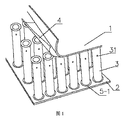
図1に示すように、中空管を挟み込んだ金属板は、第1のパネル1と、第2のパネル2と、第1のパネル1と第2のパネル2との間の複数の中空管3とを含み、複数の中空管3の間に隙間が設けられ、中空管3と第1のパネル1、第2のパネル2とがろう付け接続される。
As shown in FIG. 1, the metal plate sandwiching the hollow tube has a plurality of hollows between the
本実施例において、中空管3は断面形状が円形であり、かつ中空構造である。隣接する中空管3の間に一定の距離が設けられる。
中空管3の上下両端にいずれもフランジ5−1が設けられ、外へ反って円形になる。中空管3のフランジ5−1と第1のパネル1、第2のパネル2とは、ろう4によりろう付け接続され、ろう4が中空管3と二つのパネルとの間に直接敷設される。
In this embodiment, the
Flange 5-1 is provided on both the upper and lower ends of the
本実施例において、ろう4は銅ろうである。第1のパネル1と第2のパネル2はいずれも平面板である。第1のパネル1、第2のパネル2、及び中空管3はいずれもステンレス鋼材質である。
中空管3に通気孔31が設けられ、通気孔31は、中空管の頂部から10mm離れた位置に設けられる。ろう付け過程において、中空管3内にシールドガスを導入し、酸素ガスの含有量が非常に低くなると、還元ガスを導入することにより、ステンレス鋼製中空管の酸化層を還元することができる。ガスは通気孔31から排出することができる。
In this embodiment, the
The
好ましくは、中空管に通気孔から発泡材料、例えばポリウレタン原液を充填して、中空管内で泡沫に発泡してもよく、また、中空管内に発泡無機粒子が予め充填されてもよい。
別に好ましくは、各中空管の配列隙間に無機綿、例えば岩綿が充填されてもよい。岩綿は塊状であり、そのサイズは中空管の間の隙間に適合することにより、各岩綿を中空管の隙間にぎゅっと詰め込んで締着する。
Preferably, the hollow tube may be filled with a foam material, for example, a polyurethane stock solution from the ventilation holes to foam foam in the hollow tube, or the hollow tube may be pre-filled with foamed inorganic particles.
Alternatively, the arrangement gap of each hollow tube may be filled with inorganic cotton, for example, rock cotton. The rocks are lumpy and their size fits into the gaps between the hollow tubes so that each rock is tightly packed and tightened into the gaps between the hollow tubes.
図2に示すように、実施例1との相違点は、ろう4’を穴抜きして折り曲げることにより、中空管3をろう4’のフランジ41’に被覆して位置決めすることである。
As shown in FIG. 2, the difference from the first embodiment, 'by bending and punching, a
図3に示すように、実施例2を基に、ろう4’は非中空管の位置に透かし彫り6が設けられる。
As shown in FIG. 3, based on the second embodiment, the wax 4'is provided with a
図4に示すように、実施例2との相違点は、複数の中空管3の前側と後側の縁部に枠7が設けられ、枠7がステンレス鋼材質であり、枠7がろう付けにより第1のパネル1、第2のパネル2と一体として接続されることである。
As shown in FIG. 4, the difference from the second embodiment, the
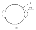
図5に示すように、実施例1との相違点は、中空管3の上下両端にいずれもフランジ5−2が設けられ、フランジ5−2が、中空管に対称に設けられた二つの半円形構造を含み、中空管のフランジ5−2と第1のパネル、第2のパネルとがろう付け接続されることである。
As shown in FIG. 5, the difference from the first embodiment is that flanges 5-2 are provided on both upper and lower ends of the
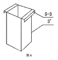
図6に示すように、実施例1との相違点は、中空管3’の断面形状が正方形であり、中空管3’の上下両端にいずれもフランジ5−3が設けられ、フランジ5−3が、中空管に対称に設けられた二つの曲げ角構造を含み、中空管のフランジ5−3と第1のパネル、第2のパネルとがろう付け接続されることである。
As shown in FIG. 6, the difference from the first embodiment is that the hollow tube 3'has a square cross-sectional shape, and flanges 5-3 are provided on both upper and lower ends of the hollow tube 3', and the
図7に示すように、実施例2との相違点は、複数の中空管3の間には、貫通したガス流路8が設けられ、中空管3と第1のパネル1、第2のパネル2との間は、高温ガスがガス流路8を前後、左右流通し加熱してろう付けを実現することである。
As shown in FIG. 7, the difference from the second embodiment is that a penetrating
具体的には、中空管3は円管であり、中空管の数量は必要に応じて選択することができる。隣接する中空管3は間隔を置いて配列されて、横方向ガス流路81と縦方向ガス流路82を形成する。高温ガスは、横方向ガス流路81と縦方向ガス流路82から金属板の内部空洞に入る。ここで、中空管3と第1のパネル、第2のパネルとは、ろうにより、高温ガスを導入してろう付け接続され、ろうが中空管と第1のパネル、第2のパネルとの間に敷設される。ろうは銅ろうであり、高温ガスの温度は銅の融点よりも大きく、かつ第1のパネル、第2のパネル、及び中空管の材質の融点よりも低く、このようにして、高温ガスにより銅ろうを溶かし、液状銅ろうを用いて母材を濡し、接続隙間を充填すると共に母材と相互に拡散して接続固定を実現する。ろう付けが完了した後、中空管3と第1のパネル、第2のパネルとの間は、冷ガスが横方向ガス流路81と縦方向ガス流路82を前後、左右流通し冷却して成形される。ここで、高温ガスと冷ガスはいずれも窒素ガスである。
Specifically, the
隣接する二列の中空管の間に接続シートが挿入され、接続シートに分岐が設けられ、分岐の位置は通気孔31の位置に対応し、分岐は孔に挿入し、接続シートの一端から隣接する2列の中空管に空気抽出を行うことにより、中空管が無酸素環境になる。
A connection sheet is inserted between two adjacent rows of hollow pipes, the connection sheet is provided with a branch, the position of the branch corresponds to the position of the
図8に示すように、実施例1又は実施例2との相違点は、第1のパネル1’と第2のパネル2’はいずれも曲面板であることである。中空管3の両端とパネルの接触面とは垂直に接続される。曲面板の線種は弧形であり、複数の中空管3は間隔を置いて配列され、各中空管3の軸は、その対応する弧形の接線と垂直であり、このようにして、中空管3とパネルとの間の接続強度を向上させ、中空管の複数の位置が溶接されないか、又は隙間又は空洞等が発生して、ろう付けが均一にならないことを回避し、本技術手段は全体的な強度及び品質を大幅に向上させることができる。
As shown in FIG. 8, the difference from the first or second embodiment is that both the first panel 1'and the second panel 2'are curved plates. Both ends of the
第1のパネル1’と第2のパネル2’は、形状が同じである。曲面板の中心角を大きく設計してもよいし、小さく設計してもよい。
他の構造は実施例1又は実施例2と同じである。
The first panel 1'and the second panel 2'have the same shape. The central angle of the curved plate may be designed to be large or small.
Other structures are the same as in Example 1 or Example 2.
図9に示すように、実施例8との相違点は、第1のパネル1’が曲面板であり、第2のパネル2が平面板であり、曲面板と接続された中空管3”の端が曲面板の接触面に平行であるか又は略平行であり、中空管3”の上下両端にいずれもフランジが設けられ、フランジは曲面板の接触面に平行であるか又は略平行であり、それにより中空管3”と曲面板を堅牢に溶接し、中空管の複数の位置を溶接しないか、又は隙間又は空間等が発生することを回避し、全体的な強度及び品質を大幅に向上させることである。
他の構造は実施例8と同じである。
As shown in FIG. 9, the difference from the eighth embodiment is that the first panel 1'is a curved plate, the
Other structures are the same as in Example 8.
図10に示すように、実施例8との相違点は、第1のパネル1’と第2のパネル2’がいずれも曲面板であり、曲面板の線種が波形であることである。
他の構造は実施例8と同じである。
As shown in FIG. 10, the difference from the eighth embodiment is that both the first panel 1'and the second panel 2'are curved plates, and the line type of the curved plate is corrugated.
Other structures are the same as in Example 8.
実施例8との相違点は、第1のパネルと第2のパネルがいずれも平面板であり、かつ第1のパネルと第2のパネルが平行ではなく、即ち第1のパネルが傾斜して配置され、第2のパネルが水平に設けられることである。第1のパネルと接続された中空管の端は斜面であり、中空管の上下両端にいずれもフランジが設けられ、フランジは第1のパネルの接触面に平行であるか又は略平行であり、それにより中空管と曲面板を堅牢に溶接し、中空管の複数の位置を溶接しないか、又は隙間又は空間等が発生することを回避し、全体的な強度及び品質を大幅に向上させる。
他の構造は実施例8と同じである。
The difference from the eighth embodiment is that both the first panel and the second panel are flat plates, and the first panel and the second panel are not parallel, that is, the first panel is inclined. It is arranged and the second panel is provided horizontally. The end of the hollow tube connected to the first panel is a slope, and flanges are provided on both the upper and lower ends of the hollow tube, and the flanges are parallel to or substantially parallel to the contact surface of the first panel. Yes, thereby firmly welding the hollow tube and the curved plate, not welding multiple positions of the hollow tube, or avoiding the occurrence of gaps or spaces, etc., greatly improving the overall strength and quality. Improve.
Other structures are the same as in Example 8.
図11に示すように、実施例2との相違点は、本実施例のろう4’がシート状であり、ろう1を穴抜きして折り曲げることである。
本実施例において、複数の中空管3は複数の列に配列され、各縦列は1枚のろう4’に対応し、ろう4’上の孔42’は各列の中空管3の数量に対応する。例えば、複数の中空管3を9列に配列し、各縦列の上端及び下端はいずれも1枚のろう4’に対応し、合計で18枚のろうである。
As shown in FIG. 11, the difference from the second embodiment is that the wax 4'of the present embodiment has a sheet shape, and the
In this embodiment, the plurality of
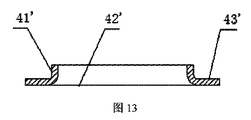
図12及び図13に示すように、実施例12との相違点は、ろう4’が棒状であり、ろう4’が直接複数の壁43’付きの孔42’を接続リブ44’により一体として接続して形成されることである。 As shown in FIGS. 12 and 13, the difference from the 12th embodiment is that the wax 4'is rod-shaped, and the wax 4'directly integrates the holes 42'with a plurality of walls 43' by the connecting ribs 44'. It is formed by connecting.
図14に示すように、実施例13との相違点は、ろう4’に孔42’の縁部に沿って外向きに延伸する位置決め突起45’が設けられ、孔42’がフランジ41’により中空管3を巻き付け、位置決め突起45’により中空管を係止することである。
本実施例の位置決め突起45’は2つあり、かつ対称に設けられ、位置決め突起45’は棒状である。
他の構造は実施例13と同じである。
As shown in FIG. 14, the difference from the thirteenth embodiment is that the wax 4'is provided with a positioning protrusion 45'that extends outward along the edge of the hole 42', and the hole 42'is provided by the flange 41'. The
There are two positioning protrusions 45'in this embodiment, and they are provided symmetrically, and the positioning protrusions 45'are rod-shaped.
Other structures are the same as in Example 13.
図15に示すように、実施例14との相違点は、位置決め突起45’が4つあり、かつ対称に設けられることである。ろう4’は一枚全体であり、かつろう4’は非中空管の位置で透かし彫りにされるか又は穴抜きされ、即ち孔42’と孔42’は、ろう接続リブ46’により接続される。
ろう接続リブ46’に溝461’が設けられ、ろうを大幅に節約する。
他の構造は実施例14と同じである。
As shown in FIG. 15, the difference from the 14th embodiment is that there are four positioning protrusions 45'and they are provided symmetrically. Wax 4 'is a single sheet, and wax 4' is or piercing is to fretwork at the position of the non-hollow tube, i.e. the '
Grooves 461'are provided in the brazing connection ribs 46', which greatly saves brazing .
Other structures are the same as in Example 14.
図16に示すように、実施例12との相違点は、中空管がろうにより位置決めされず、金属シート9により位置決めされることである。ろうは中空管とパネルとの間に平坦に敷かれる。
例えば、隣接する2つの横列の中空管3の上端と下端は、それぞれ1枚の金属シート9を共用し、かつ中空管3の上下両端にいずれもフランジ5−1が設けられ、金属シート9は横列の各中空管の上端/下端のフランジと溶接接続され、金属シート9は、好ましくはフランジ5−1の底面と溶接接続され、例えば抵抗溶接方式で溶接される。金属シート9の材質はいずれもステンレス鋼である。
As shown in FIG. 16, the difference from the twelfth embodiment is that the hollow tube is not positioned by the wax but is positioned by the
For example, the upper end and the lower end of two adjacent horizontal
本実施例の金属シートの位置決め構造により、複数の中空管3を一体として形成し、即ち一定の規格のモジュールに形成し、第1のパネル1、第2のパネル2、及び中空管3を組み立てると、複数の中空管を一体として配置して、組立速度を大幅に向上させ、それにより作業効率を向上させることができる。
また、このような全体的な位置決めの方式により、各中空管が変位、転倒しないことを保証し、中空管の位置の正確性を大幅に向上させ、それによりろう付けの品質を向上させることができる。
By the positioning structure of the metal sheet of this embodiment, a plurality of
In addition, such an overall positioning method ensures that each hollow tube does not displace or tip over, greatly improving the position accuracy of the hollow tube and thereby improving the quality of brazing . be able to.
図17に示すように、実施例12との相違点は、中空管3がろうにより位置決めされず、金属線材10により位置決めされることである。ろうは中空管とパネルとの間に平坦に敷かれる。
As shown in FIG. 17, the differences from the
例えば、各列の中空管3の上端と下端の両側は、それぞれ1本の金属線材10を共用し、金属線材10は各中空管のフランジ5−1と溶接されて、金属線材10により該列の中空管3を一体として接続する。さらに2つの斜列の中空管を選択し、それらの上下両端にそれぞれ金属線材10が溶接され、このようにして、各横列の中空管内に、いずれも2つの中空管が斜列の金属線材によって接続され、このような接続方式は、全部の中空管を一定の規格のモジュールに形成させ、即ち一体として接続し、以下の利点を有する:一方では、中空管とパネルを組み立てる過程において、組立速度を大幅に向上させ、それにより作業効率を向上させることができ、他方では、各中空管が変位、転倒しないことを保証し、中空管の位置の正確性を大幅に向上させ、それによりろう付けの品質を向上させることができる。
金属線材10は線状や棒状構造であり、材質がステンレス鋼線材である。
For example, both the upper end and the lower end of the
The
実施例12との相違点は、中空管の上端と下端のろう配置方式が異なることである。例えば、中空管の上端に対して、各縦列は1枚のろうに対応し、ろう上の孔は各列の中空管の数量と対応し、中空管の下端に対して、隣接する2縦列が1枚のろうに対応し、各枚のろう上の孔は隣接する2縦列の中空管の数量に対応する。
他の構造は実施例12と同じである。
The difference from the twelfth embodiment is that the brazing arrangement method at the upper end and the lower end of the hollow tube is different. For example, each column corresponds to one wax with respect to the upper end of the hollow tube, the holes on the brazing correspond to the number of hollow tubes in each row, and are adjacent to the lower end of the hollow tube. The two columns correspond to one wax , and the holes on each wax correspond to the number of hollow tubes in two adjacent columns.
Other structures are the same as in Example 12.
実施例1との相違点は、中空管の角の数が五角形より多くかつ十角形以下、例えば六角形管、七角形管、八角形管又は九角形管であることである。 The difference from the first embodiment is that the hollow tube has more corners than a pentagon and is less than a decagon, for example, a hexagonal tube, a heptagonal tube, an octagonal tube or a nonagonal tube.
図18に示すように、橋構造であり、その橋体11は橋台111、横梁112、支持梁113及び橋床版114を含み、横梁112が橋台111に設けられ、支持梁113が支承115により複数の横梁112を跨がり、橋床版114が支持梁113に接続される。
橋台111、横梁112、支持梁113及び橋床版114のうちの少なくとも一種の構造は、実施例1〜実施例19のいずれか一項に記載の中空管を挟み込んだ金属板で製造される。ここで、支持梁113と橋床版114はいずれも中空管を挟み込んだ1枚の金属板で製造されてもよいし、中空管を挟み込んだ複数枚の金属板を接合して構成されてもよい。橋台111、横梁112はいずれも中空管を挟み込んだ4枚の金属板を接合して柱状構造に形成される。
As shown in FIG. 18, it is a bridge structure, the
The structure of at least one of the
各金属板の間は橋構造に溶接接続され、かつボルトにより補強される。
本実施例の金属板で製造された橋体は、強度が高く、耐圧性に優れて、振動に耐え、自重が軽く、防火で、取り外し可能である。
The metal plates are welded to the bridge structure and reinforced with bolts.
The bridge body made of the metal plate of this embodiment has high strength, excellent pressure resistance, withstands vibration, has a light weight, is fireproof, and is removable.
図19に示すように、ドアは、ドア体12を含み、ドア体12が実施例1〜実施例19のいずれか一項に記載の中空管を挟み込んだ金属板で製造される。
サンドイッチ金属板材の外層に木皮、ペイント等の表面化粧材121が被覆される。
本実施例の金属板で製造されたドアは、強度が大きく、保温性に優れて、自重が軽く、防火である。
As shown in FIG. 19, the door includes a
The outer layer of the sandwich metal plate is coated with a surface
The door made of the metal plate of this embodiment has high strength, excellent heat retention, light weight, and fire protection.
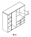
図20に示すように、収納棚は、棚本体13を含み、棚本体13内に仕切り板131が設けられ、ここで、棚本体13と仕切り板131の少なくとも一種の構造が実施例1〜実施例19のいずれか一項に記載の中空管を挟み込んだ金属板で製造される。複数枚の金属板は複数のボルトにより棚本体構造に接続される。仕切り板131は水平仕切り板と垂直仕切り板に分けられ、垂直仕切り板と棚本体の内壁とはボルトにより接続され、水平仕切り板と棚本体及び垂直仕切り板ともボルトにより接続される。
本実施例の金属板で製造された収納棚は、強度が大きく、保温性に優れて、自重が軽く、防火である。
As shown in FIG. 20, the storage shelf includes the
The storage shelf made of the metal plate of this embodiment has high strength, excellent heat retention, light weight, and fire protection.
図21に示すように、真空管路は、管体14を含み、管体14が実施例8に記載の中空管を挟み込んだ4枚の金属板で製造され、かつ断面形状が円形の管路構造に接合される。
複数の金属板は、溶接の方式で一体として組み立てられ、かつボルトにより補強される。
該真空管路は、ハイパーループ輸送等に用いることができる。
As shown in FIG. 21, the vacuum tube includes a
The plurality of metal plates are assembled together by a welding method and reinforced by bolts.
The vacuum tube can be used for hyperloop transportation and the like.
図22に示すように、コンテナであり、そのコンテナ本体15は頂板151、底板152、側板153及び端板154を含み、コンテナ本体15の一端にコンテナドアが設けられ、コンテナ本体15の二つの端部に枠155が設けられ、コンテナ本体15の片隅に吊り孔156が設けられる。
As shown in FIG. 22, it is a container, the container
ここで、頂板151、底板152、側板153、端板154、コンテナドア及び枠155のうちの少なくとも一種の構造は、実施例1〜実施例19のいずれか一項に記載の中空管を挟み込んだ金属板で製造される。頂板151、底板152、側板153、端板154、コンテナドア及び枠155は溶接接続され、かつボルトにより補強される。
Here, at least one structure of the
図23に示すように、スーツケースであり、その本体16は、実施例1〜実施例19のいずれか一項に記載の中空管を挟み込んだ金属板で製造される。
サンドイッチ金属板材の外層にレザー又はペイント等の表面化粧材が被覆される。
As shown in FIG. 23, it is a suitcase, and the
The outer layer of the sandwich metal plate is coated with a surface decorative material such as leather or paint.
図24に示すように、トンネルであり、その本体17は内張171で製造され、本体17の内部上方に切分け板172が接続され、内張171と切分け板172の少なくとも一種の構造が実施例1〜実施例19のいずれか一項に記載の中空管を挟み込んだ金属板で製造される。内張は、複数枚の金属板を溶接すると共に螺着してトンネル本体を構成し、切分け板172と内張171の内部空洞はボルトにより接続される。
As shown in FIG. 24, it is a tunnel, the
道路であり、実施例1〜実施例19のいずれか一項に記載の中空管を挟み込んだ金属板の複数を接合して製造され、ボルトにより接続され、このようにして、1枚の金属板が損傷されると、直接取り外して新しい金属板で変換することができ、交通輸送に影響を与えない。 It is a road, manufactured by joining a plurality of metal plates sandwiching the hollow pipe according to any one of Examples 1 to 19, and connected by bolts, thus one metal. If the plate is damaged, it can be removed directly and converted with a new metal plate, which does not affect traffic.
図25に示すように、乗用車は、車体18を含み、車体がエンジンカバー181、フロントバンパブラケット182、フレーム183、ルーフ184、フロントフィンダー185、フロントドア186、バックドア187、トランクリッド188を含み、ここで、エンジンカバー181、フロントバンパブラケット182、フレーム183、ルーフ184、フロントフィンダー185、フロントドア186、バックドア187、トランクリッド188のうちの少なくとも一種の構造が実施例1〜実施例19のいずれか一項に記載の中空管を挟み込んだ金属板で製造される。金属板の間、金属板と車体の他の部品の間は、ヒンジ接続、溶接、螺着等の方式で車体構造に接続されてもよい。
As shown in FIG. 25, the passenger car includes a
図26に示すように、バラストレス軌道であり、その軌道本体19は基礎191、軌道板192及び締結システム193を含み、基礎191と軌道板192が柔軟性接着剤194により接続される。
ここで、基礎191と軌道板192のうちの少なくとも一種の構造は、実施例1〜実施例19のいずれか一項に記載の中空管を挟み込んだ金属板を接合して構成され、溶接及び螺着のうちの少なくとも一方により固定されてもよい。
As shown in FIG. 26, it is a rose stress track, the
Here, the structure of at least one of the foundation 191 and the
図27に示すように、レールトレインであり、その車体20は、車室壁板201及び床板202を含み、列車が真空管路203内を走行すると、真空管路203内に軌道板204が設けられ、その車室壁板201、床板202及び軌道板204のうちの少なくとも一種の構造が実施例1〜実施例19のいずれか一項に記載の中空管を挟み込んだ金属板で製造される。その真空管路203は、実施例8に記載の中空管を挟み込んだ金属板で製造される。金属板間、金属板と車体の他の部品の間は、ヒンジ接続、溶接、螺着等の方式で車体構造、管路構造又は軌道板構造に接続されてもよい。
As shown in FIG. 27, it is a rail train, and the vehicle body 20 includes a passenger
図28に示すように、船構造であり、その船体21はボディ211、補強板212、船室仕切り板213及び補強仕切り板214を含み、前記ボディ211、補強板212、船室仕切り板213及び補強仕切り板214のうちの少なくとも一種の構造が実施例1〜実施例19のいずれか一項に記載の中空管を挟み込んだ金属板で製造される。金属板の間、金属板と船体の他の部品の間は、ヒンジ接続、溶接、螺着等の方式で船体構造に接続されてもよい。
As shown in FIG. 28, the hull structure includes a body 211, a reinforcing plate 212, a
図29に示すように、飛行機であり、その機体22はボディ、翼及び飛行機底部を含み、ここで、ボディがボディ外板221、ボディ外板221内部空洞に設けられた第1の仕切り枠222、及びトラス桁223を含む。翼は、翼外板224、及び翼外板の内部空洞に設けられた縦壁225を含む。飛行機の底部は、床板226、ボディ外板221及びボディ外板の内部空洞に設けられた第2の仕切り枠227、横梁228を含む。
As shown in FIG. 29, it is an airplane, the
ここで、ボディ外板221、第1の仕切り枠222、トラス桁223、翼外板224、縦壁225、床板226、第2の仕切り枠227及び横梁228のうちの少なくとも一種の構造は、実施例1〜実施例19のいずれか一項に記載の中空管を挟み込んだ金属板で製造される。通常、機体はいずれも弧形構造であり、好ましくは、実施例8に記載の中空管を挟み込んだ金属板で製造される。
金属板の間、金属板と機体の他の部品の間は、ヒンジ接続、溶接、螺着等の方式で機体構造に接続されてもよい。
Here, at least one structure of the body outer plate 221 and the first partition frame 222, the
Between the metal plates, and between the metal plates and other parts of the airframe, they may be connected to the airframe structure by a method such as hinge connection, welding, or screwing.
図30に示すように、建造物支柱であり、その柱体23は、実施例1〜実施例19のいずれか一項に記載の中空管を挟み込んだ4枚の金属板で製造され、4枚の金属板が「口」字形に囲み、互いに接続されて建造物支柱に構成される。
金属板の間は、溶接、螺着等の方式で接続されてもよい。
明らかに、当業者は本発明の精神及び範囲から逸脱することなく、本発明に対して様々な修正及び変形を行うことができる。このようにして、本発明のこれらの修正と変形が本発明の特許請求の範囲とその同等技術の範囲内に属すれば、本発明もこれらの修正及び変形を含む。
As shown in FIG. 30, it is a building pillar, and the
The metal plates may be connected by a method such as welding or screwing.
Obviously, one of ordinary skill in the art can make various modifications and modifications to the invention without departing from the spirit and scope of the invention. In this way, the present invention also includes these modifications and modifications, provided that these modifications and modifications of the present invention fall within the scope of the claims of the present invention and the equivalent technology thereof.
Claims (10)
或いは、前記中空管の材質がステンレス鋼、炭素鋼、チタン又は銅合金板であることを特徴とする請求項1または2に記載の中空管を挟み込んだ金属板。 The material of at least one of the first panel and the second panel is stainless steel, carbon steel, titanium or a copper alloy plate.
Alternatively, the metal plate sandwiching the hollow tube according to claim 1 or 2, wherein the material of the hollow tube is stainless steel, carbon steel, titanium, or a copper alloy plate.
Applications Claiming Priority (13)
| Application Number | Priority Date | Filing Date | Title |
|---|---|---|---|
| CN201610967446.0 | 2016-10-31 | ||
| CN201610967446.0A CN108005302A (en) | 2016-10-31 | 2016-10-31 | A kind of flange core |
| CN201710069311.7A CN108397679B (en) | 2017-02-08 | 2017-02-08 | Sandwich metal plate |
| CN201710069311.7 | 2017-02-08 | ||
| CN201710465352.8 | 2017-06-19 | ||
| CN201710465352.8A CN109128567B (en) | 2017-06-19 | 2017-06-19 | Brazing material structure, brazing sandwich composite board and assembling method thereof |
| CN201710621595.6 | 2017-07-27 | ||
| CN201710621594.1A CN109304528A (en) | 2017-07-27 | 2017-07-27 | A kind of soldering sandwich composite board position limiting structure |
| CN201710621595.6A CN109304901A (en) | 2017-07-27 | 2017-07-27 | A kind of soldering sandwich composite board position limiting structure |
| CN201710621594.1 | 2017-07-27 | ||
| CN201710700964 | 2017-08-16 | ||
| CN201710700964.0 | 2017-08-16 | ||
| PCT/CN2017/103301 WO2018076984A1 (en) | 2016-10-31 | 2017-09-26 | Metal plate having hollow tubes sandwiched therein and its use |
Publications (3)
| Publication Number | Publication Date |
|---|---|
| JP2019508612A JP2019508612A (en) | 2019-03-28 |
| JP2019508612A5 JP2019508612A5 (en) | 2019-11-14 |
| JP6793751B2 true JP6793751B2 (en) | 2020-12-02 |
Family
ID=62024360
Family Applications (1)
| Application Number | Title | Priority Date | Filing Date |
|---|---|---|---|
| JP2018552113A Active JP6793751B2 (en) | 2016-10-31 | 2017-09-26 | Metal plate sandwiching a hollow tube and its uses |
Country Status (19)
| Country | Link |
|---|---|
| US (2) | US10920422B2 (en) |
| EP (1) | EP3351702A4 (en) |
| JP (1) | JP6793751B2 (en) |
| KR (1) | KR102184163B1 (en) |
| AU (1) | AU2017338254B2 (en) |
| CA (1) | CA3008499C (en) |
| CL (1) | CL2018001761A1 (en) |
| CO (1) | CO2018004852A2 (en) |
| CR (1) | CR20180122A (en) |
| IL (1) | IL258984B (en) |
| MX (1) | MX2018006994A (en) |
| MY (1) | MY195356A (en) |
| NZ (1) | NZ741337A (en) |
| PE (1) | PE20190951A1 (en) |
| PH (1) | PH12018500990A1 (en) |
| SA (1) | SA518400080B1 (en) |
| SG (1) | SG11201805175VA (en) |
| WO (1) | WO2018076984A1 (en) |
| ZA (1) | ZA201801128B (en) |
Cited By (1)
| Publication number | Priority date | Publication date | Assignee | Title |
|---|---|---|---|---|
| US12064827B1 (en) * | 2021-06-13 | 2024-08-20 | Garvey Holding LLC | Methods, systems, and apparatus for joining metallic fabrics |
Families Citing this family (13)
| Publication number | Priority date | Publication date | Assignee | Title |
|---|---|---|---|---|
| WO2020106960A1 (en) * | 2018-11-21 | 2020-05-28 | Autotelic Holding Llc | Core for building |
| CN109530956B (en) * | 2018-12-28 | 2020-12-22 | 远大可建科技有限公司 | Brazing filler metal, core tube and brazing filler metal welding device and method |
| JP7272194B2 (en) * | 2019-09-11 | 2023-05-12 | 積水ハウス株式会社 | CLT panel reinforcement structure |
| CN110801090A (en) * | 2019-11-22 | 2020-02-18 | 耒阳市汉客箱包有限公司 | Wear-resisting travelling basket |
| WO2021261122A1 (en) * | 2020-06-23 | 2021-12-30 | 富士フイルム株式会社 | Structure and method for manufacturing structure |
| CN111824325B (en) * | 2020-07-09 | 2022-01-11 | 漳浦县金浦钢丝厂 | High-strength compression-resistant galvanized plate |
| CN111843098B (en) * | 2020-07-23 | 2021-05-04 | 吉林大学 | Clamp for brazing aluminum honeycomb panel and brazing process |
| CN112356523B (en) * | 2020-08-29 | 2021-12-07 | 南京航空航天大学 | Gradient lattice energy absorption structure constructed by chiral cell based on programmable rigidity and 3D printing method thereof |
| CN112317896B (en) * | 2020-10-23 | 2022-02-22 | 航天特种材料及工艺技术研究所 | Integrated preparation method of vacuum packaging outer protection structure |
| KR102277253B1 (en) * | 2020-11-26 | 2021-07-13 | 코오롱이앤씨 주식회사 | Rapid construction process Rahmen structure system and construction methods for utilizing the CTS slab |
| KR102509900B1 (en) * | 2021-03-03 | 2023-03-15 | 코오롱이앤씨 주식회사 | Rapid construction method using unit member |
| CN113510443B (en) * | 2021-05-13 | 2023-06-23 | 国网上海市电力公司 | Manufacturing process of electric power crimping pipe |
| CN114012352B (en) * | 2021-09-25 | 2024-03-19 | 苏州华创特材股份有限公司 | Production process of steel pipe for side wall string beam of electric locomotive |
Family Cites Families (100)
| Publication number | Priority date | Publication date | Assignee | Title |
|---|---|---|---|---|
| US1465653A (en) * | 1921-10-31 | 1923-08-21 | Axel E Olander | Wall construction |
| US2538495A (en) * | 1947-01-04 | 1951-01-16 | Bell Telephone Labor Inc | Metallic container sealing method |
| US2837788A (en) * | 1955-07-18 | 1958-06-10 | Dante V Mazzocco | Panel core constructions |
| US3072225A (en) * | 1955-10-17 | 1963-01-08 | Solar Aircraft Co | Honeycomb sandwich structure |
| US2822609A (en) * | 1955-11-10 | 1958-02-11 | Niphos Corp | Brazing process |
| US3061054A (en) * | 1958-08-18 | 1962-10-30 | Milo R Simmonds | Fastening methods and means for structural sandwiches |
| US3110961A (en) * | 1959-04-06 | 1963-11-19 | North American Aviation Inc | Honeycomb sandwich panel brazing |
| US3156041A (en) * | 1960-04-18 | 1964-11-10 | Frank M Gault | Method of soldering and brazing structural elements |
| US3328218A (en) * | 1962-04-09 | 1967-06-27 | Noyes Howard | Process of making a structural element |
| US3355850A (en) * | 1964-02-14 | 1967-12-05 | Frederick W Rohe | Insert with ends riveted to panel skins |
| US3490187A (en) * | 1967-05-23 | 1970-01-20 | Harry K Stauffer | Building component |
| US3526072A (en) * | 1968-03-29 | 1970-09-01 | James R Campbell | Load distributing system for panels incorporating honeycomb core |
| US3750248A (en) * | 1968-06-14 | 1973-08-07 | Emhart Corp | Method for making evaporator or condenser construction |
| US3664906A (en) * | 1970-01-26 | 1972-05-23 | Du Pont | Structural panel of ribbed structures of thermoplastic resin |
| AU470726B2 (en) * | 1972-04-19 | 1976-03-25 | Industrialised Building Systems Limited | Improvements in or relating to structural building panels |
| US4027058A (en) * | 1975-07-23 | 1977-05-31 | Wootten William A | Folded structural panel |
| US4034135A (en) * | 1975-11-20 | 1977-07-05 | Passmore Michael Edward Anthon | Rigid structure |
| US4257998A (en) * | 1978-05-01 | 1981-03-24 | The Boenig Company | Method of making a cellular core with internal septum |
| SE420750B (en) * | 1978-11-17 | 1981-10-26 | Ingemanssons Ingenjorsbyra Ab | SOUND-INSULATING BUILDING ELEMENT WITH GREAT STUFF |
| USRE35098E (en) * | 1979-12-20 | 1995-11-28 | Modine Manufacturing Co. | Method of making a heat exchanger |
| US4348848A (en) * | 1980-04-01 | 1982-09-14 | Denzer Walter L | Segregated slab structural products |
| US4470357A (en) * | 1983-01-17 | 1984-09-11 | Caesar Sanzaro | Laminated panels for vault construction |
| US4489234A (en) * | 1983-03-25 | 1984-12-18 | General Electric Company | Radiant-energy heating and/or cooking apparatus with honeycomb coverplate |
| US4572700A (en) * | 1983-03-31 | 1986-02-25 | Monsanto Company | Elongated bendable drainage mat |
| GB2167699B (en) * | 1984-12-04 | 1988-04-27 | Sanden Corp | A method for producing a heat exchanger |
| DE3624986A1 (en) * | 1986-07-24 | 1988-02-04 | Focke & Co | MACHINE, PARTICULARLY PACKING MACHINE |
| US5360500A (en) * | 1986-11-20 | 1994-11-01 | Dunlop Limited | Method of producing light-weight high-strength stiff panels |
| JPH069738Y2 (en) * | 1987-01-23 | 1994-03-16 | 株式会社ゼクセル | Brazing structure of pipe material |
| US5197244A (en) * | 1988-10-31 | 1993-03-30 | Kabushiki Kaisha Toshiba | Interior panel unit for permitting arrangement of cables and devices on room floor |
| US5116689A (en) * | 1988-11-07 | 1992-05-26 | Rohr Industries, Inc. | Apparatus and method for selectively increasing density and thermal conductivity of honeycomb structures |
| US5150520A (en) * | 1989-12-14 | 1992-09-29 | The Allen Group Inc. | Heat exchanger and method of assembly thereof |
| US5433151A (en) * | 1990-09-07 | 1995-07-18 | Hitachi, Ltd. | Railway car body structures and methods of making them using welded honeycomb panels connected in an edge to edge relation |
| US5036913A (en) * | 1990-11-05 | 1991-08-06 | Valeo Engine Cooling, Incorporated | Vehicle radiator with tube to header joint formed of a composite weld and solder bond |
| JPH04288957A (en) * | 1991-03-05 | 1992-10-14 | Toshiba Corp | Manufacture of fin-tube heat exchanger for concentrator |
| US5188879A (en) * | 1991-07-15 | 1993-02-23 | Sorrento Engineering Corporation | Polyimide foam filled structures |
| US5487930A (en) * | 1991-10-03 | 1996-01-30 | Tolo, Inc. | Three structure structural element with interlocking ribbing |
| FR2687465A1 (en) * | 1992-02-14 | 1993-08-20 | Valeo Thermique Moteur Sa | CONNECTING TUBING FOR A HEAT EXCHANGER FLUID BOX AND FLUID BOX PROVIDED WITH SUCH A TUBING. |
| JPH083443Y2 (en) * | 1992-04-24 | 1996-01-31 | 有限会社クリーン・アップ・システム | Drainage / water retention device |
| US5445861A (en) * | 1992-09-04 | 1995-08-29 | The Boeing Company | Lightweight honeycomb panel structure |
| KR950009505B1 (en) * | 1993-03-05 | 1995-08-23 | 주식회사두원공조 | Method manufacturing heat-exchanger used in motors |
| AU697396B2 (en) * | 1994-01-26 | 1998-10-08 | Peter Sing | Sandwich construction building materials |
| CZ290540B6 (en) * | 1994-03-31 | 2002-08-14 | Corus Uk Limited | Pre-fabricated double skin panel |
| WO1995026856A1 (en) * | 1994-03-31 | 1995-10-12 | British Steel Plc | Improvements in and relating to double skin composite structures |
| US5492069A (en) * | 1994-07-18 | 1996-02-20 | E. I. Du Pont De Nemours And Company | Pallet assembly |
| JP3172986B2 (en) * | 1994-12-21 | 2001-06-04 | 日本軽金属株式会社 | Honeycomb panel |
| JPH08174727A (en) * | 1994-12-21 | 1996-07-09 | Nippon Light Metal Co Ltd | Honeycomb panel |
| JPH08192485A (en) * | 1995-01-19 | 1996-07-30 | Nippon Light Metal Co Ltd | Honeycomb panel and manufacture thereof |
| US5716693A (en) * | 1995-11-06 | 1998-02-10 | Pittman; Douglas E. | High strength, lightweight pressurized structure for use as the skin of a spacecraft or other vehicle |
| DE19615505C2 (en) * | 1996-04-19 | 2001-09-06 | Bluemle Blueco Technik | Double plate body |
| US6297489B1 (en) * | 1996-05-02 | 2001-10-02 | Hamamatsu Photonics K.K. | Electron tube having a photoelectron confining mechanism |
| US6004652A (en) * | 1996-09-13 | 1999-12-21 | Clark; Brian Hall | Structural dimple panel |
| US6412243B1 (en) * | 1997-04-30 | 2002-07-02 | Franklin S. Sutelan | Ultra-lite modular composite building system |
| US6055790A (en) * | 1998-05-18 | 2000-05-02 | The United States Of America As Represented By The Secretary Of The Air Force | Thermal conductive insert for sandwich structures |
| GB2344864A (en) * | 1998-12-17 | 2000-06-21 | Textron Fastening Syst Ltd | Blind fastener |
| US6129146A (en) * | 1999-05-17 | 2000-10-10 | Krueger; David L. | Manifold for a brazed radiator |
| US6834469B2 (en) * | 2001-01-24 | 2004-12-28 | Geotek, Inc. | Utility line support member |
| FR2820716B1 (en) * | 2001-02-15 | 2003-05-30 | Eads Airbus Sa | PROCESS FOR DEFROSTING BY FORCED CIRCULATION OF A FLUID, OF A REACTION ENGINE AIR INLET COVER AND DEVICE FOR ITS IMPLEMENTATION |
| US7575795B2 (en) * | 2002-04-02 | 2009-08-18 | Seamless Alteratory Technologies, Inc (Satech) | Impact absorbing safety matting system with elastomeric sub-surface structure |
| JP2004108070A (en) | 2002-09-19 | 2004-04-08 | Kaho Seisakusho:Kk | Perspective/shielding louver device |
| US20060151155A1 (en) * | 2003-01-27 | 2006-07-13 | Showa Denko K.K. | Heat exchanger and process for fabricating same |
| US6817586B1 (en) * | 2003-08-08 | 2004-11-16 | Ching-Chiang Lin | Paper pallet |
| KR200350066Y1 (en) * | 2003-09-24 | 2004-05-14 | 박기호 | A method of producing honeycomb structure |
| JP4038497B2 (en) * | 2004-07-06 | 2008-01-23 | 株式会社ミヤテック | Thermal insulation panel |
| US10352484B2 (en) * | 2004-08-05 | 2019-07-16 | Faurecia Emissions Control Technologies Germany Gmbh | Exhaust system |
| JP4696236B2 (en) * | 2005-02-16 | 2011-06-08 | 国立大学法人広島大学 | Method for producing chondroitin |
| US7958681B2 (en) * | 2005-06-02 | 2011-06-14 | Moller Jr Jorgen J | Modular floor tile with nonslip insert system |
| CN1748486A (en) * | 2005-08-22 | 2006-03-22 | 薛斌凯 | Honeycomb composite plate core board |
| US20070256379A1 (en) * | 2006-05-08 | 2007-11-08 | Edwards Christopher M | Composite panels |
| DE102006028956A1 (en) * | 2006-06-23 | 2008-01-24 | Airbus Deutschland Gmbh | Side fairing for an aircraft includes gastight film that surrounds the component with the hollow chambers in a gastight manner after application of a vacuum to evacuate the hollow chambers of the component |
| US8141723B2 (en) * | 2006-08-18 | 2012-03-27 | Plano Molding Company | Inverted cell honeycomb structure shelving |
| WO2008127301A1 (en) * | 2006-10-27 | 2008-10-23 | University Of Virginia Patent Foundation | Manufacture of lattice truss structures from monolithic materials |
| CN100560350C (en) * | 2007-02-23 | 2009-11-18 | 辽宁科技大学 | Metallic honeycomb sandwich assembly energy-absorbing construction material and preparation method thereof |
| US8097106B2 (en) * | 2007-06-28 | 2012-01-17 | The Boeing Company | Method for fabricating composite structures having reinforced edge bonded joints |
| FI125708B (en) * | 2007-09-11 | 2016-01-15 | Outokumpu Oy | Panel design |
| DE102007051628B4 (en) * | 2007-10-26 | 2009-11-26 | Zimmer, Günther | Telescopic dowel II and setting method |
| JP5004371B2 (en) * | 2008-04-30 | 2012-08-22 | キョーラク株式会社 | Sandwich panel core, sandwich panel core molding method, and sandwich panel and sandwich panel molding method |
| US8528299B2 (en) * | 2008-12-23 | 2013-09-10 | Woodwelding Ag | Method of anchoring a connector, and connector |
| WO2010135565A2 (en) * | 2009-05-21 | 2010-11-25 | Edizone, Llc | Cushions comprising core structures having joiner ribs and related methods |
| CN201567737U (en) | 2009-10-28 | 2010-09-01 | 江苏华浠新型建材有限公司 | Metallic face aluminum honeycomb coreboard |
| US8403007B1 (en) * | 2009-10-29 | 2013-03-26 | Vittorio Marinelli | Rivet plumbing repair apparatus and method |
| US8590247B2 (en) * | 2009-11-12 | 2013-11-26 | Duke Ellington Cooke | Ceiling anchoring device with locking rail system |
| US20110240280A1 (en) * | 2010-03-31 | 2011-10-06 | Kabushiki Kaisha Kobe Seiko Sho (Kobe Steel, Ltd.) | Aluminum alloy brazing sheet and heat exchanger |
| DE102010018676B4 (en) * | 2010-04-28 | 2012-02-09 | Dbw Holding Gmbh | Heat insulation or insulating sheet in the vehicle area from a flat semi-finished metal |
| US9845600B2 (en) * | 2011-07-01 | 2017-12-19 | Embry-Riddle Aeronautical University, Inc. | Highly vented truss wall honeycomb structures |
| CN202359876U (en) | 2011-11-24 | 2012-08-01 | 张梦之 | Paper honeycomb composite baffle wall |
| EP2816166B1 (en) * | 2011-12-20 | 2020-04-22 | Elesdopa, S.L. | Module for building façades and method of use in construction |
| CN103192551B (en) | 2012-01-09 | 2016-12-07 | 辽宁辽杰科技有限公司 | A kind of hollow sandwich sheet with honeycomb texture central layer and preparation method thereof |
| EP2917426B1 (en) * | 2012-11-08 | 2023-06-07 | IIS Institute for Independent Studies Zürich GmbH | Building envelope and method for setting the temperature in a building |
| HUE042164T2 (en) * | 2013-03-20 | 2019-06-28 | Ruag Schweiz Ag | Lightweight support structure, method of producing a lightweight support structure, composite sandwich panel and method of poducing a composite sandwich panel |
| JP2014188996A (en) * | 2013-03-28 | 2014-10-06 | Mitsubishi Aircraft Corp | Honeycomb core sandwich structure repair method, and repair result |
| BR112016007339B1 (en) * | 2013-10-04 | 2021-11-03 | Zephyros, Inc | METHOD OF FIXING A COMPONENT TO A BEEHIVE-TYPE STRUCTURE |
| JP2016017666A (en) * | 2014-07-07 | 2016-02-01 | 株式会社ケーヒン・サーマル・テクノロジー | Heat exchanger and its process of manufacture |
| US11313623B2 (en) * | 2015-03-02 | 2022-04-26 | Denso Corporation | Heat exchanger |
| JP2017029989A (en) * | 2015-07-29 | 2017-02-09 | 株式会社Uacj | Manufacturing method of aluminum structure |
| EP3350457B1 (en) * | 2015-09-17 | 2019-12-18 | SPS Technologies, LLC | Adjustable insert for sandwich structures |
| KR101774322B1 (en) * | 2015-12-22 | 2017-09-04 | 엘지전자 주식회사 | Air conditioner and Manufacturing methods |
| US10016955B2 (en) * | 2016-04-19 | 2018-07-10 | The Boeing Company | Panel apparatus including multiple panels and mechanical fasteners and methods of assembling the panel apparatus |
| JP6635022B2 (en) * | 2016-12-26 | 2020-01-22 | 株式会社デンソー | Intercooler and method of manufacturing the intercooler |
| JP6805055B2 (en) * | 2017-04-05 | 2020-12-23 | リンナイ株式会社 | Fin tube heat exchanger |
| US11022384B2 (en) * | 2018-02-19 | 2021-06-01 | Honeywell International Inc. | Framed heat exchanger core design-fabrication |
-
2017
- 2017-09-26 NZ NZ741337A patent/NZ741337A/en unknown
- 2017-09-26 SG SG11201805175VA patent/SG11201805175VA/en unknown
- 2017-09-26 CR CR20180122A patent/CR20180122A/en unknown
- 2017-09-26 MX MX2018006994A patent/MX2018006994A/en unknown
- 2017-09-26 CA CA3008499A patent/CA3008499C/en active Active
- 2017-09-26 US US15/774,951 patent/US10920422B2/en active Active
- 2017-09-26 KR KR1020187025262A patent/KR102184163B1/en active IP Right Grant
- 2017-09-26 JP JP2018552113A patent/JP6793751B2/en active Active
- 2017-09-26 WO PCT/CN2017/103301 patent/WO2018076984A1/en active Application Filing
- 2017-09-26 MY MYPI2018700455A patent/MY195356A/en unknown
- 2017-09-26 AU AU2017338254A patent/AU2017338254B2/en active Active
- 2017-09-26 PE PE2018000503A patent/PE20190951A1/en unknown
- 2017-09-26 EP EP17821773.3A patent/EP3351702A4/en active Pending
-
2018
- 2018-02-19 ZA ZA2018/01128A patent/ZA201801128B/en unknown
- 2018-04-26 IL IL258984A patent/IL258984B/en unknown
- 2018-05-07 CO CONC2018/0004852A patent/CO2018004852A2/en unknown
- 2018-05-08 PH PH12018500990A patent/PH12018500990A1/en unknown
- 2018-06-27 CL CL2018001761A patent/CL2018001761A1/en unknown
- 2018-09-20 SA SA518400080A patent/SA518400080B1/en unknown
-
2020
- 2020-03-24 US US16/828,783 patent/US11499313B2/en active Active
Cited By (1)
| Publication number | Priority date | Publication date | Assignee | Title |
|---|---|---|---|---|
| US12064827B1 (en) * | 2021-06-13 | 2024-08-20 | Garvey Holding LLC | Methods, systems, and apparatus for joining metallic fabrics |
Also Published As
| Publication number | Publication date |
|---|---|
| US11499313B2 (en) | 2022-11-15 |
| US20180328037A1 (en) | 2018-11-15 |
| KR20180111898A (en) | 2018-10-11 |
| CL2018001761A1 (en) | 2018-08-24 |
| SA518400080B1 (en) | 2022-03-09 |
| EP3351702A1 (en) | 2018-07-25 |
| SG11201805175VA (en) | 2018-07-30 |
| EP3351702A4 (en) | 2019-04-10 |
| CA3008499A1 (en) | 2018-05-03 |
| AU2017338254B2 (en) | 2019-12-12 |
| US20200217072A1 (en) | 2020-07-09 |
| ZA201801128B (en) | 2019-07-31 |
| CR20180122A (en) | 2018-07-04 |
| PH12018500990A1 (en) | 2018-11-12 |
| MX2018006994A (en) | 2018-11-09 |
| MY195356A (en) | 2023-01-16 |
| PE20190951A1 (en) | 2019-07-04 |
| NZ741337A (en) | 2020-07-31 |
| CA3008499C (en) | 2021-04-13 |
| WO2018076984A1 (en) | 2018-05-03 |
| AU2017338254A1 (en) | 2018-05-17 |
| KR102184163B1 (en) | 2020-11-30 |
| JP2019508612A (en) | 2019-03-28 |
| IL258984B (en) | 2022-04-01 |
| BR112018067879A2 (en) | 2019-12-03 |
| US10920422B2 (en) | 2021-02-16 |
| CO2018004852A2 (en) | 2018-07-31 |
| IL258984A (en) | 2018-07-31 |
Similar Documents
| Publication | Publication Date | Title |
|---|---|---|
| JP6793751B2 (en) | Metal plate sandwiching a hollow tube and its uses | |
| JP2019508612A5 (en) | ||
| CN109398595A (en) | A kind of maritime vehicles structure | |
| JP5008320B2 (en) | Ship compartment module | |
| US20120169087A1 (en) | Fiber-reinforced floor system | |
| EP2110291B1 (en) | Car body structure for a railway vehicle | |
| US7353960B2 (en) | Cargo container with insulated floor | |
| US20150336732A1 (en) | Intermodal Container and Method of Constructing Same | |
| KR101185518B1 (en) | A cargo tank having wall with wire cellular structure | |
| US6626319B2 (en) | Integrated tank erection and support carriage for a semi-membrane LNG tank | |
| JP2013532784A5 (en) | ||
| CN107796266B (en) | Lightweight erecting heat-insulation cabin and preparation method thereof | |
| TWI708007B (en) | Metal plate with hollow tube and its use | |
| BR112018067879B1 (en) | METAL PLATE WITH PRESSED HOLLOW TUBES AND ITS USE | |
| KR101430063B1 (en) | Bi-oblique tip tank for lng | |
| US20150361660A1 (en) | Modular Vertical Stacking Load Bearing Wall and Shoring System | |
| OA18874A (en) | Metal plate having hollow tubes sandwiched therein and its use | |
| CN218665036U (en) | Floor inner plate stool type hoisting transportation and in-place system | |
| TWI396644B (en) | Cabin with heat-insulating structure | |
| JP3714577B2 (en) | Inboard panel type thermal insulation method | |
| CN117449525A (en) | Assembled prefabricated light steel composite inner wallboard | |
| JP3221887U (en) | Outer wall structure of frozen / cold storage warehouse | |
| US2138399A (en) | Vehicle body | |
| RU29886U1 (en) | Vehicle partition | |
| US2987328A (en) | Building and air distributing structure |
Legal Events
| Date | Code | Title | Description |
|---|---|---|---|
| A521 | Request for written amendment filed |
Free format text: JAPANESE INTERMEDIATE CODE: A523 Effective date: 20180626 |
|
| A621 | Written request for application examination |
Free format text: JAPANESE INTERMEDIATE CODE: A621 Effective date: 20180626 |
|
| A131 | Notification of reasons for refusal |
Free format text: JAPANESE INTERMEDIATE CODE: A131 Effective date: 20190701 |
|
| A977 | Report on retrieval |
Free format text: JAPANESE INTERMEDIATE CODE: A971007 Effective date: 20190628 |
|
| A524 | Written submission of copy of amendment under article 19 pct |
Free format text: JAPANESE INTERMEDIATE CODE: A524 Effective date: 20191001 |
|
| A131 | Notification of reasons for refusal |
Free format text: JAPANESE INTERMEDIATE CODE: A131 Effective date: 20200217 |
|
| A521 | Request for written amendment filed |
Free format text: JAPANESE INTERMEDIATE CODE: A523 Effective date: 20200518 |
|
| TRDD | Decision of grant or rejection written | ||
| A01 | Written decision to grant a patent or to grant a registration (utility model) |
Free format text: JAPANESE INTERMEDIATE CODE: A01 Effective date: 20201026 |
|
| A61 | First payment of annual fees (during grant procedure) |
Free format text: JAPANESE INTERMEDIATE CODE: A61 Effective date: 20201110 |
|
| R150 | Certificate of patent or registration of utility model |
Ref document number: 6793751 Country of ref document: JP Free format text: JAPANESE INTERMEDIATE CODE: R150 |
|
| R250 | Receipt of annual fees |
Free format text: JAPANESE INTERMEDIATE CODE: R250 |