JP6635022B2 - Intercooler and method of manufacturing the intercooler - Google Patents
Intercooler and method of manufacturing the intercooler Download PDFInfo
- Publication number
- JP6635022B2 JP6635022B2 JP2016251185A JP2016251185A JP6635022B2 JP 6635022 B2 JP6635022 B2 JP 6635022B2 JP 2016251185 A JP2016251185 A JP 2016251185A JP 2016251185 A JP2016251185 A JP 2016251185A JP 6635022 B2 JP6635022 B2 JP 6635022B2
- Authority
- JP
- Japan
- Prior art keywords
- duct
- pipe
- tube
- flat
- laminated
- Prior art date
- Legal status (The legal status is an assumption and is not a legal conclusion. Google has not performed a legal analysis and makes no representation as to the accuracy of the status listed.)
- Expired - Fee Related
Links
Images


Classifications
-
- F—MECHANICAL ENGINEERING; LIGHTING; HEATING; WEAPONS; BLASTING
- F02—COMBUSTION ENGINES; HOT-GAS OR COMBUSTION-PRODUCT ENGINE PLANTS
- F02B—INTERNAL-COMBUSTION PISTON ENGINES; COMBUSTION ENGINES IN GENERAL
- F02B29/00—Engines characterised by provision for charging or scavenging not provided for in groups F02B25/00, F02B27/00 or F02B33/00 - F02B39/00; Details thereof
- F02B29/04—Cooling of air intake supply
- F02B29/0406—Layout of the intake air cooling or coolant circuit
-
- B—PERFORMING OPERATIONS; TRANSPORTING
- B23—MACHINE TOOLS; METAL-WORKING NOT OTHERWISE PROVIDED FOR
- B23K—SOLDERING OR UNSOLDERING; WELDING; CLADDING OR PLATING BY SOLDERING OR WELDING; CUTTING BY APPLYING HEAT LOCALLY, e.g. FLAME CUTTING; WORKING BY LASER BEAM
- B23K1/00—Soldering, e.g. brazing, or unsoldering
- B23K1/0008—Soldering, e.g. brazing, or unsoldering specially adapted for particular articles or work
- B23K1/0012—Brazing heat exchangers
-
- B—PERFORMING OPERATIONS; TRANSPORTING
- B23—MACHINE TOOLS; METAL-WORKING NOT OTHERWISE PROVIDED FOR
- B23K—SOLDERING OR UNSOLDERING; WELDING; CLADDING OR PLATING BY SOLDERING OR WELDING; CUTTING BY APPLYING HEAT LOCALLY, e.g. FLAME CUTTING; WORKING BY LASER BEAM
- B23K1/00—Soldering, e.g. brazing, or unsoldering
- B23K1/008—Soldering within a furnace
-
- B—PERFORMING OPERATIONS; TRANSPORTING
- B23—MACHINE TOOLS; METAL-WORKING NOT OTHERWISE PROVIDED FOR
- B23K—SOLDERING OR UNSOLDERING; WELDING; CLADDING OR PLATING BY SOLDERING OR WELDING; CUTTING BY APPLYING HEAT LOCALLY, e.g. FLAME CUTTING; WORKING BY LASER BEAM
- B23K1/00—Soldering, e.g. brazing, or unsoldering
- B23K1/19—Soldering, e.g. brazing, or unsoldering taking account of the properties of the materials to be soldered
-
- F—MECHANICAL ENGINEERING; LIGHTING; HEATING; WEAPONS; BLASTING
- F01—MACHINES OR ENGINES IN GENERAL; ENGINE PLANTS IN GENERAL; STEAM ENGINES
- F01P—COOLING OF MACHINES OR ENGINES IN GENERAL; COOLING OF INTERNAL-COMBUSTION ENGINES
- F01P11/00—Component parts, details, or accessories not provided for in, or of interest apart from, groups F01P1/00 - F01P9/00
- F01P11/04—Arrangements of liquid pipes or hoses
-
- F—MECHANICAL ENGINEERING; LIGHTING; HEATING; WEAPONS; BLASTING
- F02—COMBUSTION ENGINES; HOT-GAS OR COMBUSTION-PRODUCT ENGINE PLANTS
- F02B—INTERNAL-COMBUSTION PISTON ENGINES; COMBUSTION ENGINES IN GENERAL
- F02B29/00—Engines characterised by provision for charging or scavenging not provided for in groups F02B25/00, F02B27/00 or F02B33/00 - F02B39/00; Details thereof
- F02B29/04—Cooling of air intake supply
-
- F—MECHANICAL ENGINEERING; LIGHTING; HEATING; WEAPONS; BLASTING
- F02—COMBUSTION ENGINES; HOT-GAS OR COMBUSTION-PRODUCT ENGINE PLANTS
- F02D—CONTROLLING COMBUSTION ENGINES
- F02D23/00—Controlling engines characterised by their being supercharged
-
- F—MECHANICAL ENGINEERING; LIGHTING; HEATING; WEAPONS; BLASTING
- F02—COMBUSTION ENGINES; HOT-GAS OR COMBUSTION-PRODUCT ENGINE PLANTS
- F02M—SUPPLYING COMBUSTION ENGINES IN GENERAL WITH COMBUSTIBLE MIXTURES OR CONSTITUENTS THEREOF
- F02M31/00—Apparatus for thermally treating combustion-air, fuel, or fuel-air mixture
- F02M31/20—Apparatus for thermally treating combustion-air, fuel, or fuel-air mixture for cooling
-
- F—MECHANICAL ENGINEERING; LIGHTING; HEATING; WEAPONS; BLASTING
- F02—COMBUSTION ENGINES; HOT-GAS OR COMBUSTION-PRODUCT ENGINE PLANTS
- F02M—SUPPLYING COMBUSTION ENGINES IN GENERAL WITH COMBUSTIBLE MIXTURES OR CONSTITUENTS THEREOF
- F02M35/00—Combustion-air cleaners, air intakes, intake silencers, or induction systems specially adapted for, or arranged on, internal-combustion engines
- F02M35/10—Air intakes; Induction systems
-
- F—MECHANICAL ENGINEERING; LIGHTING; HEATING; WEAPONS; BLASTING
- F28—HEAT EXCHANGE IN GENERAL
- F28D—HEAT-EXCHANGE APPARATUS, NOT PROVIDED FOR IN ANOTHER SUBCLASS, IN WHICH THE HEAT-EXCHANGE MEDIA DO NOT COME INTO DIRECT CONTACT
- F28D9/00—Heat-exchange apparatus having stationary plate-like or laminated conduit assemblies for both heat-exchange media, the media being in contact with different sides of a conduit wall
- F28D9/0031—Heat-exchange apparatus having stationary plate-like or laminated conduit assemblies for both heat-exchange media, the media being in contact with different sides of a conduit wall the conduits for one heat-exchange medium being formed by paired plates touching each other
- F28D9/0043—Heat-exchange apparatus having stationary plate-like or laminated conduit assemblies for both heat-exchange media, the media being in contact with different sides of a conduit wall the conduits for one heat-exchange medium being formed by paired plates touching each other the plates having openings therein for circulation of at least one heat-exchange medium from one conduit to another
- F28D9/0056—Heat-exchange apparatus having stationary plate-like or laminated conduit assemblies for both heat-exchange media, the media being in contact with different sides of a conduit wall the conduits for one heat-exchange medium being formed by paired plates touching each other the plates having openings therein for circulation of at least one heat-exchange medium from one conduit to another with U-flow or serpentine-flow inside conduits; with centrally arranged openings on the plates
-
- F—MECHANICAL ENGINEERING; LIGHTING; HEATING; WEAPONS; BLASTING
- F28—HEAT EXCHANGE IN GENERAL
- F28F—DETAILS OF HEAT-EXCHANGE AND HEAT-TRANSFER APPARATUS, OF GENERAL APPLICATION
- F28F9/00—Casings; Header boxes; Auxiliary supports for elements; Auxiliary members within casings
- F28F9/001—Casings in the form of plate-like arrangements; Frames enclosing a heat exchange core
-
- B—PERFORMING OPERATIONS; TRANSPORTING
- B23—MACHINE TOOLS; METAL-WORKING NOT OTHERWISE PROVIDED FOR
- B23K—SOLDERING OR UNSOLDERING; WELDING; CLADDING OR PLATING BY SOLDERING OR WELDING; CUTTING BY APPLYING HEAT LOCALLY, e.g. FLAME CUTTING; WORKING BY LASER BEAM
- B23K2101/00—Articles made by soldering, welding or cutting
- B23K2101/006—Vehicles
-
- B—PERFORMING OPERATIONS; TRANSPORTING
- B23—MACHINE TOOLS; METAL-WORKING NOT OTHERWISE PROVIDED FOR
- B23K—SOLDERING OR UNSOLDERING; WELDING; CLADDING OR PLATING BY SOLDERING OR WELDING; CUTTING BY APPLYING HEAT LOCALLY, e.g. FLAME CUTTING; WORKING BY LASER BEAM
- B23K2101/00—Articles made by soldering, welding or cutting
- B23K2101/04—Tubular or hollow articles
- B23K2101/14—Heat exchangers
-
- B—PERFORMING OPERATIONS; TRANSPORTING
- B23—MACHINE TOOLS; METAL-WORKING NOT OTHERWISE PROVIDED FOR
- B23K—SOLDERING OR UNSOLDERING; WELDING; CLADDING OR PLATING BY SOLDERING OR WELDING; CUTTING BY APPLYING HEAT LOCALLY, e.g. FLAME CUTTING; WORKING BY LASER BEAM
- B23K2103/00—Materials to be soldered, welded or cut
- B23K2103/08—Non-ferrous metals or alloys
- B23K2103/10—Aluminium or alloys thereof
-
- F—MECHANICAL ENGINEERING; LIGHTING; HEATING; WEAPONS; BLASTING
- F28—HEAT EXCHANGE IN GENERAL
- F28D—HEAT-EXCHANGE APPARATUS, NOT PROVIDED FOR IN ANOTHER SUBCLASS, IN WHICH THE HEAT-EXCHANGE MEDIA DO NOT COME INTO DIRECT CONTACT
- F28D21/00—Heat-exchange apparatus not covered by any of the groups F28D1/00 - F28D20/00
- F28D2021/0019—Other heat exchangers for particular applications; Heat exchange systems not otherwise provided for
- F28D2021/008—Other heat exchangers for particular applications; Heat exchange systems not otherwise provided for for vehicles
- F28D2021/0082—Charged air coolers
-
- F—MECHANICAL ENGINEERING; LIGHTING; HEATING; WEAPONS; BLASTING
- F28—HEAT EXCHANGE IN GENERAL
- F28F—DETAILS OF HEAT-EXCHANGE AND HEAT-TRANSFER APPARATUS, OF GENERAL APPLICATION
- F28F2275/00—Fastening; Joining
- F28F2275/04—Fastening; Joining by brazing
- F28F2275/045—Fastening; Joining by brazing with particular processing steps, e.g. by allowing displacement of parts during brazing or by using a reservoir for storing brazing material
-
- Y—GENERAL TAGGING OF NEW TECHNOLOGICAL DEVELOPMENTS; GENERAL TAGGING OF CROSS-SECTIONAL TECHNOLOGIES SPANNING OVER SEVERAL SECTIONS OF THE IPC; TECHNICAL SUBJECTS COVERED BY FORMER USPC CROSS-REFERENCE ART COLLECTIONS [XRACs] AND DIGESTS
- Y02—TECHNOLOGIES OR APPLICATIONS FOR MITIGATION OR ADAPTATION AGAINST CLIMATE CHANGE
- Y02T—CLIMATE CHANGE MITIGATION TECHNOLOGIES RELATED TO TRANSPORTATION
- Y02T10/00—Road transport of goods or passengers
- Y02T10/10—Internal combustion engine [ICE] based vehicles
- Y02T10/12—Improving ICE efficiencies
Description
本発明は、過給機を介して内燃機関に供給される過給吸気を冷却するインタークーラおよびそのインタークーラの製造方法に関するものである。 The present invention relates to an intercooler for cooling supercharged intake air supplied to an internal combustion engine via a supercharger, and a method for manufacturing the intercooler.
従来、この種のインタークーラとして、例えば特許文献1に記載されたものがある。この特許文献1に記載されたインタークーラは、過給吸気が流れるダクトと、そのダクト内収容された積層コアとを備えている。そして、その積層コアは、チューブ積層方向に積層された複数の冷却チューブで構成されている。
Conventionally, as this type of intercooler, for example, there is one described in
また、積層コアに対するチューブ積層方向の一方側には、冷却チューブへ冷却水を流入させる冷却水入口としてのパイプと、冷却チューブから冷却水を流出させる冷却水出口としてのパイプとが設けられている。 Further, on one side of the tube stacking direction with respect to the laminated core, a pipe as a cooling water inlet for flowing cooling water into the cooling tube and a pipe as a cooling water outlet for flowing cooling water from the cooling tube are provided. .
特許文献1のインタークーラでは、上記の2本のパイプはそれぞれ、複数の冷却チューブへ連通する連通管として設けられている。そして、その2本のパイプはダクトからチューブ積層方向の一方側へ突き出るようにそのダクトに接続され、チューブ積層方向に直交する方向へパイプ先端が向くように曲げられている。そのため、2本のパイプはそれぞれ、そのパイプの曲げRやパイプ径の寸法によって、インタークーラの本体部分に相当するダクトおよび積層コアからチューブ積層方向の一方側へ大きく飛び出すことになる。その結果として、例えば、車両のエンジンルーム内に配置されるインタークーラの搭載性が大きく損なわれるおそれがある。発明者の詳細な検討の結果、以上のようなことが見出された。
In the intercooler of
本発明は上記点に鑑み、積層された複数の冷却チューブを有するインタークーラにおいて、連通管を原因としたチューブ積層方向への全幅拡大を抑制することを目的とする。 In view of the above, an object of the present invention is to suppress an increase in the overall width in the tube stacking direction due to a communication pipe in an intercooler having a plurality of stacked cooling tubes.
上記目的を達成するため、請求項1に記載されたインタークーラは、
過給機(SC)を介して内燃機関(105)に供給される過給吸気を冷却するインタークーラであって、
チューブ積層方向(DRs)に積層された複数の冷却チューブ(21)を有する積層コア(2)と、
積層コアに対しチューブ積層方向の一方側に配置され、複数の冷却チューブへ連通する連通管(4、5)と、
過給吸気が流通するダクト通路(13)が形成され、そのダクト通路に積層コアを収容するダクト(1)と、
積層部材(7)とを備え、
複数の冷却チューブ内には、過給吸気と熱交換する冷却流体が流通し、
連通管は、複数の冷却チューブへ接続される扁平管部(41、51)を有し、
扁平管部は、チューブ積層方向と交差する方向へ拡がる扁平断面形状を成しており、ダクトに対するチューブ積層方向の一方側に配置されると共に、そのダクトに接合され、
ダクトにはダクト連通孔(124a、125a)が形成され、
そのダクトは、扁平管部に接合されたダクト接合部(126、127)をダクト連通孔の周りに有し、
扁平管部は、ダクト連通孔を介して複数の冷却チューブへ連通しており、
積層部材は、扁平管部とダクト接合部との間に配置されその扁平管部とダクト接合部とのそれぞれに対して積層された積層板部(71)と、その積層板部と一体構成された支持部(72)とを有し、
ダクトには、チューブ積層方向に交差するダクト方向(DRd)の一方側に設けられ過給吸気が流入するダクト通路の流入口(13a)と、ダクト方向の他方側に設けられ過給吸気が流出するダクト通路の流出口(13b)とが形成され、
連通管は、支持部に接合された管接合部(42、52)と、冷却流体を連通管へ流入させ又は冷却流体を連通管から流出させる外部配管部材(93、94)が接続される管先端部(44、54)とを有し、且つ、チューブ積層方向とダクト方向とに交差する管延伸方向(DRp)に延びるように形成され、
ダクト接合部は、積層板部が扁平管部とダクト接合部とのそれぞれに接合されることにより、積層板部を介して扁平管部に接合されており、
管接合部は扁平管部よりも管延伸方向の一方側に配置され、
管先端部は管接合部よりも管延伸方向の一方側に配置されている。
In order to achieve the above object, the intercooler according to
An intercooler for cooling supercharged intake air supplied to an internal combustion engine (105) via a supercharger (SC),
A laminated core (2) having a plurality of cooling tubes (21) laminated in a tube laminating direction (DRs);
A communication pipe (4, 5) arranged on one side in the tube stacking direction with respect to the stacked core and communicating with a plurality of cooling tubes ;
A duct (13) in which a supercharged air flows is formed, and a duct (1) accommodating the laminated core in the duct passage;
A laminated member (7) ,
A cooling fluid that exchanges heat with the supercharged intake air flows through the plurality of cooling tubes,
The communication pipe has a flat pipe part (41, 51) connected to the plurality of cooling tubes,
The flat tube portion has a flat cross-sectional shape that extends in a direction intersecting the tube stacking direction, and is arranged on one side in the tube stacking direction with respect to the duct, and is joined to the duct,
Duct communication holes (124a, 125a) are formed in the duct,
The duct has a duct joint (126, 127) joined to the flat tube around the duct communication hole,
The flat tube portion communicates with a plurality of cooling tubes via a duct communication hole,
The laminated member is disposed between the flat tube portion and the duct joint portion, and is laminated to the flat tube portion and the duct joint portion, and is integrally formed with the laminated plate portion. And a supporting portion (72).
The duct has an inlet (13a) of a duct passage provided on one side in the duct direction (DRd) intersecting the tube stacking direction and into which the supercharged air flows, and a supercharged air provided on the other side in the duct direction. And an outlet (13b) of a duct passage that forms
The communication pipe is a pipe to which a pipe joint (42, 52) joined to the support and an external pipe member (93, 94) for allowing a cooling fluid to flow into the communication pipe or flowing a cooling fluid out of the communication pipe. A tip portion (44, 54), and formed so as to extend in a tube extending direction (DRp) intersecting the tube stacking direction and the duct direction;
The duct joint portion is joined to the flat tube portion via the laminate plate portion by joining the laminated plate portion to each of the flat tube portion and the duct joint portion,
The pipe joint is arranged on one side in the pipe extending direction than the flat pipe,
The pipe tip is arranged on one side in the pipe extending direction from the pipe joint .
上述のように、連通管の扁平管部は、チューブ積層方向と交差する方向へ拡がる扁平断面形状を成している。従って、特許文献1のインタークーラが有するパイプと比較して、チューブ積層方向の一方側への連通管の突出幅を抑えるように、その連通管を構成することが可能である。その結果、インタークーラの全幅が連通管を原因としてチューブ積層方向へ拡大することを抑制することが可能である。
As described above, the flat tube portion of the communication tube has a flat cross-sectional shape that extends in a direction intersecting the tube stacking direction. Therefore, as compared with the pipe of the intercooler of
上記目的を達成するため、請求項8に記載されたインタークーラの製造方法は、
過給機(SC)を介して内燃機関(105)に供給される過給吸気と熱交換する冷却流体が流通しチューブ積層方向(DRs)に積層された複数の冷却チューブ(21)を有し、過給吸気と冷却流体との熱交換によりその過給吸気を冷却する積層コア(2)と、
チューブ積層方向に交差するダクト方向(DRd)の一方側から他方側へと過給吸気が流通するダクト通路(13)が形成され、そのダクト通路に積層コアを収容するダクト(1)とを備えたインタークーラの製造方法であって、
ダクトを用意すること(S01)と、
扁平断面形状を成す扁平管部(41、51)と、その扁平管部よりも管延伸方向(DRp)の一方側に配置され外部配管部材(93、94)が接続される管先端部(44、54)と、管延伸方向で扁平管部と管先端部との間に配置された管接合部(42、52)とを有し、管延伸方向に延びるように形成された連通管(4、5)を用意すること(S01)と、
両面にロウ材を有する板材で構成され、積層板部(71)とその積層板部に一体構成された支持部(72)とを有する積層部材(7)を用意すること(S01)と、
管延伸方向がチューブ積層方向とダクト方向との各々に対して交差するように連通管を配置しつつ、ダクトに形成されたダクト連通孔(124a、125a)を介して扁平管部を複数の冷却チューブへ連通させると共に、積層板部に対するチューブ積層方向の一方側に扁平管部を積層配置し、且つ積層板部に対するチューブ積層方向の他方側に、ダクトのうちダクト連通孔の周りを構成するダクト接合部(126、127)を積層配置すること(S02)と、
積層配置の後に、ダクトと連通管と積層部材とを一旦加熱することにより、ロウ材によって、積層板部を介して扁平管部をダクト接合部にロウ付けすると共に管接合部を支持部にロウ付けすること(S03)とを含む。
In order to achieve the above object, a method of manufacturing an intercooler according to claim 8 is as follows.
A cooling fluid that exchanges heat with supercharged intake air supplied to the internal combustion engine (105) through the supercharger (SC) flows and has a plurality of cooling tubes (21) stacked in the tube stacking direction (DRs). A laminated core (2) for cooling the supercharged air by heat exchange between the supercharged air and the cooling fluid;
A duct passage (13) through which the supercharged air flows is formed from one side to the other side in a duct direction (DRd) intersecting the tube stacking direction, and the duct passage includes a duct (1) for accommodating a laminated core. Intercooler manufacturing method,
Prepare a duct (S01)
A flat tube portion (41, 51) having a flat cross-sectional shape, and a tube tip portion (44) which is disposed on one side of the flat tube portion in the pipe extending direction (DRp) and is connected to an external piping member (93, 94). , 54) and a pipe joint (42, 52) disposed between the flat tube portion and the tube tip in the tube extension direction, and the communication tube (4) formed to extend in the tube extension direction. , 5) (S01),
Preparing a laminated member (7) composed of a plate material having brazing material on both sides and having a laminated plate portion (71) and a support portion (72) integrally formed with the laminated plate portion (S01);
While arranging the communication pipe so that the pipe extending direction intersects each of the tube laminating direction and the duct direction, the flat pipe part is cooled by a plurality of cooling means through the duct communication holes (124a, 125a) formed in the duct. A duct that communicates with the tube and has a flat tube portion laminated on one side in the tube laminating direction with respect to the laminated plate portion, and a duct that forms around the duct communication hole of the duct on the other side in the tube laminating direction with respect to the laminated plate portion Stacking and disposing the joints (126, 127) (S02);
After the stacking arrangement, the duct, the communication pipe, and the stacking member are heated once, so that the flat pipe section is brazed to the duct joint section via the laminated plate section by the brazing material, and the pipe joint section is brazed to the support section. (S03).
これにより、連通管を原因としたチューブ積層方向への全幅拡大が抑制されたインタークーラを製造することが可能である。 Thereby, it is possible to manufacture an intercooler in which the total width in the tube stacking direction due to the communication pipe is suppressed.
ここで、ロウ付け用のロウ材が仮に積層部材ではなくダクトの表面に予め設けられていたとすれば、一旦溶けて凝固したロウ材がロウ付け後のダクトの表面に残り、インタークーラの外観を損なうことになる。また別の例として、そのロウ材が仮に積層部材ではなく連通管の表面に予め設けられていたとすれば、一旦溶けて凝固したロウ材がロウ付け後の連通管のうち管先端部の表面にも残り、管先端部に対し外部配管部材を良好に接続しにくくなる。 Here, if the brazing material for brazing is provided in advance on the surface of the duct instead of the laminated member, the brazing material once melted and solidified remains on the surface of the duct after brazing, and the appearance of the intercooler is changed. You will lose. As another example, if the brazing material is provided in advance on the surface of the communicating pipe instead of the laminated member, the brazing material once melted and solidified is formed on the surface of the leading end of the communicating pipe after brazing. This also makes it difficult to satisfactorily connect the external piping member to the pipe tip.
これに対し、上述のインタークーラの製造方法によれば、積層部材は、両面にロウ材を有する板材で構成されており、その積層部材の積層板部を介して連通管の扁平管部はダクト接合部にロウ付けされる。従って、インタークーラの外観と管先端部に対する良好な外部配管部材の接続性とを損なわないように、連通管の扁平管部をダクト接合部にロウ付けすることが可能である。 On the other hand, according to the above-described method for manufacturing an intercooler, the laminated member is formed of a plate material having brazing material on both surfaces, and the flat tube portion of the communication pipe is ducted through the laminated plate portion of the laminated member. It is brazed to the joint. Therefore, it is possible to braze the flat pipe portion of the communication pipe to the duct joint so as not to impair the appearance of the intercooler and the good connectivity of the external pipe member to the pipe tip.
なお、特許請求の範囲およびこの欄で記載した括弧内の各符号は、後述する実施形態に記載の具体的内容との対応関係を示す一例である。 Each symbol in the claims and parentheses described in this section is an example showing a correspondence relationship with specific contents described in the embodiment described later.
以下、図面を参照しながら、各実施形態を説明する。なお、以下の各実施形態相互において、互いに同一もしくは均等である部分には、図中、同一符号を付してある。 Hereinafter, each embodiment will be described with reference to the drawings. In the following embodiments, parts that are the same or equivalent are denoted by the same reference numerals in the drawings.
(第1実施形態)
以下、第1実施形態について説明する。図1および図2に示すように、本実施形態のインタークーラ100は、車両90のフロントエンジンルーム92(以下、単に「エンジンルーム92」と呼ぶ)内に配置される。図1は、車両90の前方側からエンジンルーム92内のインタークーラ100等を透過的に表した図である。図2は、エンジンルーム92内を車両90の幅方向から見たときの、インタークーラ100、エンジン105等の配置を示す図である。
(1st Embodiment)
Hereinafter, the first embodiment will be described. As shown in FIGS. 1 and 2, the
本実施形態のインタークーラ100は、過給機SCを介してエンジン105に供給される過給吸気(以下、単に「吸気」とも呼ぶ)を冷却する熱交換器である。すなわち、インタークーラ100は、過給機SCにて加圧されて高温になった吸気と冷却用の冷却流体とを熱交換させて吸気を冷却する。
The
インタークーラ100の空気流れ上流側には第1ガスタンク101aが接続される。第1ガスタンク101aの空気流れ上流側には第1吸気管102aが接続される。過給機SCによって加圧されて高温になった吸気が第1吸気管102aおよび第1ガスタンク101aをこの順に通ってインタークーラ100内を通る。
A
インタークーラ100内を通る吸気は、冷却流体と熱交換して冷却される。冷却流体は、例えばLLCである。LLCは、ロングライフクーラントの略である。すなわち、本実施形態では冷却流体は液体であるので、インタークーラ100は水冷インタークーラである。
The intake air passing through the
図2に示すように、インタークーラ100の空気流れ下流側には第2ガスタンク101bが接続される。第2ガスタンク101bの空気流れ下流側には第2吸気管102bが接続される。インタークーラ100を通過して冷却された後の吸気は、第2ガスタンク101bおよび第2吸気管102bをこの順に通る。なお、後述の説明において、第1ガスタンク101aと第2ガスタンク101bとを特に区別しない場合には、単にガスタンク101a、101bと記載する。
As shown in FIG. 2, a
第2吸気管102b内の空気流れ下流側端には、エンジン105に吸入される空気の量を調整するスロットル弁103が配置されている。また、第2吸気管102bの空気流れ下流側には、周知のインテークマニホールド104が接続されている。インテークマニホールド104の空気流れ下流側には、車両90を走行させるための駆動力を発生する内燃機関であるエンジン105が接続されている。第2吸気管102bおよびインテークマニホールド104を通過した吸気は、エンジン105内に吸入される。
At the downstream end of the air flow in the
図2に示すように、エンジンルーム92は、車室内空間108よりも車両前後方向の前方側かつエンジンフード109よりも車両上下方向の下方側に配置される。そして、エンジンルーム92内には、上述の第1吸気管102a、第1ガスタンク101a、インタークーラ100、第2ガスタンク101b、第2吸気管102b、スロットル弁103、インテークマニホールド104、エンジン105、ラジエータ106、およびコンデンサ107が配置されている。
As shown in FIG. 2, the
ラジエータ106は、エンジン冷却水と車室外の空気とを熱交換させてエンジン冷却水を冷やす熱交換器である。コンデンサ107は、車室内空調装置に用いられる冷媒と車室外の空気とを熱交換させてその冷媒を冷やす熱交換器である。車室内空調装置は、コンプレッサ、コンデンサ107、膨張弁、およびエバポレータ等を有する。その車室内空調装置の冷媒は、コンプレッサによって圧縮された後にコンデンサ107で凝縮され、その後膨張弁で減圧されて膨張した後、エバポレータに流入する。そのエバポレータでは、流入した冷媒と車室内に送られる送風空気とが熱交換することで、冷媒が蒸発すると共に、送風空気が冷やされる。
The
図2に示すように、エンジン105に対して車両前方側にラジエータ106およびコンデンサ107が配置されている。また、ラジエータ106に対して車両前方側にコンデンサ107が配置されている。
As shown in FIG. 2, a
車室内空間108を拡大するために、エンジン105をできるだけ車両90の前端に近づけて配置したいという要請がある。エンジン105を車両90の前端に近づけると、エンジン105とラジエータ106との間のクリアランスは小さくなる。このような条件の下では、インタークーラ100の熱交換性能と搭載性との両方を十分なレベルにするためには、車両上下方向におけるエンジン105の上方側に、インタークーラ100を配置することが好ましい。この結果、インタークーラ100の全体または一部は、エンジン105の直上に配置される。
There is a demand to arrange the
以下、インタークーラ100の構成について説明する。図3〜図5に示すように、インタークーラ100は、ダクト1と積層コア2と一対の結合プレート3と出口管4と入口管5と2つのキャップ6と2つの積層部材7とを、主要構成要素として備えている。
Hereinafter, the configuration of the
図3〜図8に示すように、ダクト1は矩形断面の筒形状を成している。ダクト1の内部には、過給機SCから流出した第1流体としての吸気が流通するダクト通路13が形成されている。ダクト1は、アルミニウム合金等の金属薄板を所定の形状にプレス成形した第1プレート11と第2プレート12とから構成されている。
As shown in FIGS. 3 to 8, the
また、図4および図5に示すように、ダクト1には、ダクト通路13の流入口13aがダクト方向DRdの一方側に形成され、ダクト通路13の流出口13bがダクト方向DRdの他方側に形成されている。すなわち、流入口13aはダクト方向DRdの一方側を向いて開口し、流出口13bはダクト方向DRdの他方側を向いて開口している。
As shown in FIGS. 4 and 5, in the
そのダクト通路13の流入口13aには、過給機SCからの吸気が流入する。また、ダクト通路13の流出口13bからは、ダクト通路13を通った吸気が流出する。従って、ダクト通路13内では、流入口13aから流入した吸気が、ダクト方向DRdの一方側から他方側へと流通する。なお、ダクト通路13の流入口13aと流出口13bとを総称してダクト開口13a、13bと呼ぶ。
The intake air from the supercharger SC flows into the
積層コア2は、ダクト1内に収容されている。別言すれば、ダクト1は、その積層コア2をダクト通路13に収容している。図4および図9に示すように、積層コア2は、チューブ積層方向DRsに積層された複数の冷却チューブ21を有している。その複数の冷却チューブ21はそれぞれ、チューブ積層方向DRsを短手方向とした扁平状の断面を有している。複数の冷却チューブ21内には、ダクト通路13を通る吸気と熱交換する第2流体としての冷却流体が流通する。複数の冷却チューブ21は、その吸気と冷却流体との熱交換によりその吸気を冷却する。なお、図9では、出口管4、入口管5、および積層部材7の図示は省略されている。
The
冷却チューブ21内には、伝熱面積を増加させて熱交換を促進するインナーフィン211が配置されていてもよい。冷却チューブ21は、表面にロウ材がクラッドされたアルミニウム合金等の金属からなる。
積層コア2では、互いに隣接する冷却チューブ21間を吸気が通過するようになっており、その隣接する冷却チューブ21間に、伝熱面積を増加させて熱交換を促進するアウターフィン22が配置されている。アウターフィン22は、アルミニウム合金等の金属薄板を波形状に成形したものであり、冷却チューブ21にロウ付けにて接合されている。
In the
なお、図3に示す矢印DRdはダクト方向DRdを示し、矢印DRsはチューブ積層方向DRsを示し、矢印DRwは、積層コア2の幅方向であるコア幅方向DRwを示している。そのダクト方向DRdとチューブ積層方向DRsとコア幅方向DRwは互いに交差する方向であり、厳密に言えば、互いに直交する方向である。
Note that the arrow DRd shown in FIG. 3 indicates the duct direction DRd, the arrow DRs indicates the tube stacking direction DRs, and the arrow DRw indicates the core width direction DRw which is the width direction of the stacked
図3〜図9に示すように、ダクト1の第1プレート11は、一対の第1プレート端板部111と第1プレート中央板部112とを有している。一対の第1プレート端板部111はそれぞれ、積層コア2におけるコア幅方向DRwの端面に対向して配置されており、その積層コア2の端面にロウ付けされている。第1プレート端板部111はそれぞれ、チューブ積層方向DRsに延びる板面を有している。第1プレート中央板部112は、積層コア2におけるチューブ積層方向DRsの第1端面に対向して配置されており、その積層コア2の第1端面にロウ付けされている。そして、第1プレート中央板部112は、一対の第1プレート端板部111を連結している。
As shown in FIGS. 3 to 9, the
ダクト1の第2プレート12は、一対の第2プレート端板部121と、第2プレート中央板部122と、一対のフランジ部123とを有している。一対の第2プレート端板部121はそれぞれ、積層コア2におけるコア幅方向DRwの端面に対向して配置され、チューブ積層方向DRsに延びる板面を有している。第2プレート端板部121は第1プレート端板部111の一部領域とコア幅方向DRwに重なり、第1プレート端板部111の外壁面にロウ付けされる。
The
第2プレート中央板部122は、積層コア2におけるチューブ積層方向DRsの第2端面に対向して配置されて第2プレート端板部121を連結するとともに、積層コア2の端面にロウ付けされている。その第2端面は、上記の第1端面に対するチューブ積層方向DRsの逆側の端面である。
The second plate
一対のフランジ部123はそれぞれ、第2プレート12におけるダクト方向DRdの両端部において、第2プレート端板部121および第2プレート中央板部122の端部からダクト通路13とは反対側となる外側に向かって鍔状に延びる。すなわち、ダクト1は、チューブ積層方向DRsに延びるフランジ部123を、ダクト開口13a、13bの周縁を形成するダクト端部123aにそれぞれ有している。
The pair of
そのフランジ部123は、第2プレート12が積層コア2、第1プレート11、および結合プレート3に組み付けられた際に、チューブ積層方向DRsに延びる面を有しており、結合プレート3に対向して配される。
The
第1プレート11と第2プレート12とが組み合わされることにより、ダクト1が形成され、それと共にダクト通路13も形成される。このダクト通路13は、ダクト方向DRdに沿って見たときの形状が略矩形を成す流路である。
The combination of the
一対の結合プレート3は何れも、アルミニウム合金等の金属薄板をプレス成形して略矩形の枠状に形成されている。一対の結合プレート3のうち一方の結合プレート3は、ダクト通路13の流入口13aを囲むように形成され、ダクト1の一方の端部にロウ付け接合されている。また、一対の結合プレート3のうち他方の結合プレート3は、ダクト通路13の流出口13bを囲むように形成され、ダクト1の他方の端部にロウ付け接合されている。
Each of the pair of
図10に示すように、結合プレート3には、ダクト方向DRdにおいてダクト1の外側を向いて開いた断面U字状の溝部33が形成されている。その溝部33は、その溝部33の底を形成する底壁部32と、この底壁部32の内周側縁部から立設した内周側壁部31と、底壁部32の外周側縁部から立設した外周側壁部35とを有している。詳細には、上記一方の結合プレート3の溝部33は、ダクト通路13の流入口13aを一周取り囲むようにその流入口13aの周縁に沿って延びている。そして、上記他方の結合プレート3の溝部33は、ダクト通路13の流出口13bを一周取り囲むようにその流出口13bの周縁に沿って延びている。
As shown in FIG. 10, a
また、結合プレート3における内周側壁部31と第1プレート11における外壁面とがロウ付けにより接合され、結合プレート3の底壁部32と第2プレート12のフランジ部123とがロウ付けにより接合されている。
Further, the inner peripheral
また、図4に示すように、結合プレート3は、チューブ積層方向DRsの一方側の端に一方側側縁35aを有している。この結合プレート3の一方側側縁35aは外周側壁部35の一部分である。
Further, as shown in FIG. 4, the
また、図10に示すように、結合プレート3には、内周側壁部31における底壁部32とは反対側の端部からダクト通路13側に突出する係止部36が形成されている。この係止部36は、第1プレート11におけるダクト方向DRdの端面と係合可能になっている。また、係止部36は、内周側壁部31の全周にわたって設けられている。
As shown in FIG. 10, the
そして、積層コア2を挟み込んだ第1プレート11と第2プレート12とを結合プレート3に組み付ける際には、第1プレート11が結合プレート3の内側に侵入すると、第1プレート11の端面が係止部36に係合する。これにより、第1プレート11が結合プレート3を超えてガスタンク101a、101b側に飛び出すことが防止される。
When assembling the
図6および図7に示すように、第1プレート端板部111には、結合プレート3の底壁部32と当接する突起状の位置決め突起部113が形成されている。そして、位置決め突起部113と結合プレート3の底壁部32との当接により、第1プレート11と結合プレート3とを仮組みしたときの、第1プレート11と結合プレート3とのダクト方向DRdの相対位置が決められるようになっている。
As shown in FIGS. 6 and 7, the first plate
図10に示すように、ダクト1の流入口13a側と流出口13b側との何れでも、結合プレート3の溝部33にパッキン37とガスタンク101a、101bの裾部101cとが挿入された後に、結合プレート3の外縁部34がかしめられる。これにより、結合プレート3とガスタンク101a、101bとが結合される。なお、パッキン37の材質としては、アクリル系ゴム、フッ素系ゴム、シリコン系ゴム等を採用することができる。また、ガスタンク101a、101bの材質としては、アルミニウム合金等の金属、樹脂等を採用することができる。結合プレート3の溝部33はプレス成形によって成形されており、溝部33には実質的に段差が形成されず、ほぼ平板状に形成される。そのため、パッキン37の圧縮率をほぼ均一とすることができ、良好なシール性を得ることができる。
As shown in FIG. 10, after the packing 37 and the
図6および図7に示すように、第1プレート端板部111には、第1プレート端板部111と第2プレート端板部121と結合プレート3との集合部に生じる隙間を埋める閉塞突起部114が形成されている。
As shown in FIGS. 6 and 7, the first plate
図3、図5、図11に示すように、出口管4と入口管5は部品単体としては同形状であり、共通部品となっている。出口管4と入口管5は、アルミニウム合金等の金属製パイプが成形された部材である。
As shown in FIGS. 3, 5, and 11, the
出口管4と入口管5は何れも、積層コア2が有する複数の冷却チューブ21へ連通する連通管である。従って、出口管4と入口管5とを総称して連通管4、5ともいう。本実施形態の説明において出口管4と入口管5とを特に区別せずに説明する場合には、その出口管4および入口管5を連通管4、5と呼ぶ場合がある。
Each of the
また、出口管4と入口管5は、ダクト1内に収容された積層コア2に対しチューブ積層方向DRsの一方側に配置されている。但し、入口管5は、出口管4に対しダクト方向DRdの一方側に配置されている。
The
出口管4と入口管5との機能は互いに異なっている。すなわち、入口管5には、冷却流体を入口管5へ流入させる外部配管部材としての流入ホース94が連結されており、入口管5は、その流入ホース94から入口管5に流入した冷却流体を複数の冷却チューブ21へと流す。そして、出口管4には、冷却流体を出口管4から流出させる外部配管部材としての流出ホース93が連結されており、出口管4は、複数の冷却チューブ21から出口管4に流入した冷却流体を流出ホース93へと流す。
The functions of the
また、図4および図5に示すように、出口管4の全体および入口管5の全体は、結合プレート3の一方側側縁35aよりも、チューブ積層方向DRsの一方側とは反対側の他方側に位置している。
As shown in FIGS. 4 and 5, the entirety of the
図3および図11に示すように、出口管4は、一軸方向である管延伸方向DRpに延びるように形成されており、扁平管部41と管接合部42と突部43と管先端部44とを有している。本実施形態では、その管延伸方向DRpはコア幅方向DRwに一致している。
As shown in FIGS. 3 and 11, the
また、管先端部44と突部43と管接合部42と扁平管部41はその記載順で、管延伸方向DRpの一方側から順番に並んで配置されている。すなわち、管接合部42は扁平管部41よりも管延伸方向DRpの一方側に配置され、管先端部44は管接合部42よりも管延伸方向DRpの一方側に配置されている。
The
また、出口管4は、管先端部44で管延伸方向DRpの一方側へ開口し、その管先端部44から扁平管部41にかけて中空になっている。そして、管先端部44には流出ホース93が接続され、扁平管部41は、複数の冷却チューブ21へ接続されている。従って、流出ホース93は出口管4を介して複数の冷却チューブ21へ接続される。
The
詳細には図11および図12に示すように、扁平管部41は、チューブ積層方向DRsと交差する方向へ拡がる扁平断面形状を成している。例えば本実施形態では、管先端部44内に形成された流路の流路断面積Abは、扁平管部41内においても確保されている。要するに、扁平管部41内に形成された流路の流路断面積Aaは、管先端部44内に形成された流路の流路断面積Abと同じ又はそれ以上になっている。その流路断面積Aa、流路断面積Abとは、流路の軸方向と一致する管延伸方向DRpに直交する断面における流路の断面積である。
Specifically, as shown in FIGS. 11 and 12, the
扁平管部41のうち、その扁平断面形状の短手方向の積層コア2側すなわちチューブ積層方向DRsの他方側には、貫通孔である扁平管連通孔41aが形成されている。また、ダクト1は、チューブ積層方向DRsの一方側へ円筒状に突き出た接続凸部124を第2プレート12の一部分として有しており、その接続凸部124の内側にはダクト連通孔124aが形成されている。扁平管部41は、そのダクト連通孔124aを介して複数の冷却チューブ21へ連通している。
In the
また、ダクト1は、扁平管部41に対して接合されたダクト接合部126をダクト連通孔124aの周りに有している。別言すれば、そのダクト接合部126は、接続凸部124の周りに設けられている。例えば、そのダクト接合部126は、ダクト連通孔124aおよび接続凸部124をその全周にわたって取り囲むように設けられている。
The
そのダクト接合部126は、第2プレート12の一部分であるので、図4および図11に示すように、結合プレート3の一方側側縁35aは、そのダクト接合部126よりもチューブ積層方向DRsの一方側に位置している。
Since the
また、図5および図11に示すように、ダクト接合部126は、ダクト1が管延伸方向DRpに占める範囲Wdのうち管延伸方向DRpの一方側に偏った位置に配置されている。
As shown in FIGS. 5 and 11, the duct
図11に示すように、出口管4の扁平管部41と管先端部44は何れも、管延伸方向DRpに延びる流路を内部に形成しているので、扁平管部41と管先端部44はそれぞれ、管延伸方向DRpに延びる中心軸線CLa、CLbを有している。そして、扁平管部41の中心軸線CLaは、管先端部44の中心軸線CLbに対しチューブ積層方向DRsの一方側に位置している。
As shown in FIG. 11, the
また、扁平管部41は、管先端部44側とは反対側すなわち管延伸方向DRpの他方側に他方端411を有している。その扁平管部41の他方端411にはキャップ6が接合されており、その他方端411はキャップ6によって気密に塞がれている。また、キャップ6は、管延伸方向DRpの一方側へ突き出たキャップ突部61を有し、そのキャップ突部61は扁平管部41内に嵌入されている。例えば図13に示すように、そのキャップ6は、アルミニウム合金等の金属製であり、扁平管部41側の面にロウ材層6aがクラッドされたクラッド材で構成されている。そして、そのキャップ6が扁平管部41の他方端411に密着させられた上で一旦加熱されることにより、キャップ6はその他方端411にロウ付け接合される。
Further, the
図11に示すように、出口管4の突部43は出口管4の径方向外側へ突き出ている。更に、その突部43は環形状を成すように出口管4の全周にわたって延びている。
As shown in FIG. 11, the
図11、図14〜図16に示すように、積層部材7は、アルミニウム合金等の金属製の板材が成形された部材である。
As shown in FIGS. 11 and 14 to 16, the
また、積層部材7は、ロウ付け前の部品単体としては、両面にロウ材を有する板材で構成されている。具体的に、その積層部材7は、両面にロウ材がクラッドされた板状のクラッド材で構成されている。
In addition, the
そして、インタークーラ100において積層部材7は、そのクラッドされたロウ材が溶融した後に凝固することによって、積層部材7に隣接する部材(具体的には、ダクト1および連通管4、5)にロウ付け接合されている。図11では、積層部材7のロウ付け接合されている部位に点ハッチングが施されている。また、図11に表される積層部材7は、図14のXI−XI断面でもある。
Then, in the
積層部材7は積層板部71と支持部72とを有している。積層部材7は1枚の板材から成るので、積層板部71と支持部72は互いに一体構成となっている。支持部72は積層板部71に対し管延伸方向DRpの一方側に位置している。また、支持部72は管延伸方向DRpの一方側に先端721を有している。
The
積層部材7の支持部72は、出口管4の管接合部42の外形に沿った形状を成している。具体的には、その支持部72は、その管接合部42の外形に沿った円弧状断面を有するように湾曲している。そして、支持部72は、チューブ積層方向DRsにおいて出口管4の管接合部42に対する他方側に配置され、且つ、その管接合部42に対して接合されている。それと共に、その支持部72の先端721は、出口管4の突部43に対し、管延伸方向DRpの他方側から突き当たっている。すなわち、積層部材7の支持部72は、出口管4のうち扁平管部41以外の部位に接合され、それによって積層部材7は出口管4を支持している。
The
また、図3、図6、図11に示すように、ダクト1は、ダクト通路13に対し管延伸方向DRpの一方側から面する一方側ダクト壁部115を有している。この一方側ダクト壁部115は、一対の第1プレート端板部111および一対の第2プレート端板部121のうち、ダクト通路13に対する管延伸方向DRpの一方側に配置された第1プレート端板部111および第2プレート端板部121から構成されている。積層部材7の支持部72は、その一方側ダクト壁部115よりも管延伸方向DRpの一方側に位置している。
As shown in FIGS. 3, 6, and 11, the
積層部材7の積層板部71は、出口管4の扁平管部41とダクト1のダクト接合部126との間に配置され、その扁平管部41とダクト接合部126とのそれぞれに対し密着して積層されている。
The
そのように積層された積層板部71は、扁平管部41とダクト接合部126とのそれぞれに接合されている。これにより、そのダクト接合部126は、積層板部71を介して扁平管部41に接合されている。すなわち、扁平管部41は、ダクト1に対するチューブ積層方向DRsの一方側に配置され、且つ、そのダクト1に接合されている。
The
また、積層板部71に形成された貫通孔71a内には、ダクト1の接続凸部124が嵌入されている。
The
入口管5は、上述した出口管4と同様の構成であるので、入口管5については簡単に説明する。図3、図5、図11に示すように、入口管5も出口管4と同様に、扁平管部51と管接合部52と突部53と管先端部54とを有している。そして、入口管5の扁平管部51は出口管4の扁平管部41と同様であり、入口管5の管接合部52は出口管4の管接合部42と同様であり、入口管5の突部53は出口管4の突部43と同様であり、入口管5の管先端部54は出口管4の管先端部44と同様である。
Since the
但し、その入口管5の管先端部54には流入ホース94が接続されている。なお、図11は出口管4の断面図であるが、図11では、入口管5に関連する各部の符号は、出口管4に関連する各部の符号の後に、互いが対応するように併記されている。
However, an
また、図9、図11に示すように、入口管5の扁平管部51へ連通するダクト連通孔125aと、それを形成する接続凸部125はそれぞれ、出口管4の扁平管部41へ連通するダクト連通孔124aと、それを形成する接続凸部124と同様である。また、ダクト1は、入口管5の扁平管部51に対して接合されたダクト接合部127を有しており、そのダクト接合部127は、出口管4の扁平管部41に対して接合されたダクト接合部126と同様である。
As shown in FIGS. 9 and 11, the
上述したように構成されるインタークーラ100の製造は、図17のフローチャートに従って進む。すなわち、インタークーラ100を製造するに当たっては、まず、準備工程に対応するステップS01にて、インタークーラ100を構成するダクト1、積層コア2、結合プレート3、出口管4、入口管5、キャップ6、および積層部材7が用意される。
The manufacture of the
具体的にこのステップS01で用意される部品はロウ付け前の部品である。すなわち、ステップS01では、ロウ付け前のダクト1の構成部品、積層コア2の構成部品、結合プレート3、出口管4、入口管5、キャップ6、および積層部材7が用意される。例えば、そのダクト1の構成部品とは、ロウ付け前の第1プレート11および第2プレート12などであり、積層コア2の構成部品とは、ロウ付け前の冷却チューブ21を構成する複数の部品およびアウターフィン22などである。なお、各構成部品を用意する順番に先後の限定はなく、更に言えば、全部の構成部品が同時に用意されてもよい。
Specifically, the components prepared in step S01 are components before brazing. That is, in step S01, the components of the
続く、組立工程に対応するステップS02にて、ステップS01で用意された各部品が仮組みされる。要するに、ステップS02では、ダクト1の構成部品、積層コア2の構成部品、結合プレート3、出口管4、入口管5、キャップ6、および積層部材7が仮組みされ、それによりインタークーラ仮組み体が構成される。
Subsequently, in step S02 corresponding to the assembling process, the components prepared in step S01 are temporarily assembled. In short, in step S02, the components of the
例えばそのインタークーラ仮組み体では、管延伸方向DRpがチューブ積層方向DRsとダクト方向DRdとの各々に対して交差するように、厳密には直交するように、連通管4、5としての出口管4と入口管5とが配置される。そして、それぞれの連通管4、5については、ダクト1に形成されたダクト連通孔124a、125aを介して扁平管部41、51が複数の冷却チューブ21へ連通させられる。それと共に、扁平管部41、51は、積層板部71に対するチューブ積層方向DRsの一方側に積層配置され、且つ、ダクト接合部126、127は、その積層板部71に対するチューブ積層方向DRsの他方側に積層配置される。
For example, in the intercooler temporary assembly, the outlet pipes as the
この仮組み状態では、インタークーラ仮組み体の各構成部品が、ロウ付けされる箇所にて互いに密着するように、図示しない治具等にて保持されている。 In this tentatively assembled state, the components of the intercooler tentatively assembled body are held by a jig or the like (not shown) so as to be in close contact with each other at the portion to be brazed.
続く、ロウ付け工程に対応するステップS03にて、インタークーラ仮組み体が炉中で一旦加熱され、それにより、インタークーラ仮組み体の各構成部品が相互にロウ付けされる。例えば出口管4と入口管5とのそれぞれでは、積層部材7の表面にクラッドされたロウ材によって、扁平管部41、51が積層部材7の積層板部71を介してダクト接合部126、127にロウ付けされると共に、管接合部42、52が積層部材7の支持部72にロウ付けされる。
Subsequently, in step S03 corresponding to the brazing step, the intercooler temporary assembly is once heated in a furnace, whereby the components of the intercooler temporary assembly are brazed to each other. For example, in each of the
上述したように、本実施形態によれば、図11に示すように、出口管4の扁平管部41は、チューブ積層方向DRsと交差する方向へ拡がる扁平断面形状を成している。そして、入口管5の扁平管部51もこれと同様である。従って、特許文献1のインタークーラが有するパイプと比較して、チューブ積層方向DRsの一方側への出口管4および入口管5の突出幅を抑えるように、その出口管4および入口管5を構成することが可能である。その結果、インタークーラ100の全幅が出口管4および入口管5を原因としてチューブ積層方向DRsへ拡大することを抑制することが可能である。
As described above, according to the present embodiment, as shown in FIG. 11, the
別言すれば、扁平形状を有する連通管4、5をダクト1上に設けることで、冷却水配管である連通管4、5がチューブ積層方向DRsへ飛び出すことを抑えることができ、エンジン105周りへのインタークーラ100の搭載性を向上させることが可能である。
In other words, by providing the
そして、出口管4および入口管5を原因としたチューブ積層方向DRsへの全幅拡大が抑制されたインタークーラ100を、図17のフローチャートに従って製造することが可能である。
Then, it is possible to manufacture the
ここで、本実施形態の積層部材7は、ロウ付け前の部品単体としては、両面にロウ材がクラッドされたクラッド材で構成されている。これとは異なり、ロウ付け用のロウ材が仮に積層部材7ではなくダクト1の表面に予め設けられていたとすれば、一旦溶けて凝固したロウ材がロウ付け後のダクト1の表面に残り、インタークーラ100の外観を損なうことになる。また別の例として、そのロウ材が仮に積層部材7ではなく連通管4、5の表面に予め設けられていたとすれば、一旦溶けて凝固したロウ材がロウ付け後の連通管4、5のうち管先端部44、54の表面にも残り、その管先端部44、54に対し外部配管部材93、94を良好に接続しにくくなる。更に言えば、パイプの外側表面にロウ材がクラッドされたクラッド材は一般的ではない。
Here, the
これに対し、本実施形態のインタークーラ100の製造方法によれば、ロウ付け前の積層部材7は、両面にロウ材を有する板材で構成されており、その積層部材7の積層板部71を介して連通管4、5の扁平管部41、51はダクト接合部126、127にロウ付けされる。従って、インタークーラ100の外観と管先端部44、54に対する良好な外部配管部材93、94の接続性とを損なわないように、連通管4、5の扁平管部41、51をダクト接合部126、127に対しロウ付けすることが可能である。
On the other hand, according to the method for manufacturing the
このように連通管4、5をダクト1にロウ付け接合する上で積層部材7の積層板部71は必須の構成要素であるので、積層部材7は、連通管4、5を設ける上での追加部品とはならない。そして、図11に示すように、支持部72と連通管4、5の管接合部42、52とのロウ付け接合によって、積層部材7は、連通管4、5を補強する補強機能を併せ持っている。すなわち、連通管4、5は扁平化により部分的に断面係数が低下し曲げ剛性が弱くなるところ、本実施形態では、追加部品無くシンプルな構成で連通管4、5を補強することができ、その連通管4、5の剛性を確保することができる。要するに、連通管4、5とダクト1とのロウ付けと、連通管4、5の剛性確保とを両立させることができる。
As described above, since the
また、本実施形態によれば、連通管4、5のうちダクト1上に設けられた扁平管部41、51は扁平断面形状を成している。そして、連通管4、5はそれぞれ、チューブ積層方向DRsと交差する管延伸方向DRpに延びるように形成されている。従って、チューブ積層方向DRsへの配管の飛び出しを抑えて、車両90に対するインタークーラ100の良好な搭載性を得ることができる。
Further, according to the present embodiment, the
また、本実施形態によれば、図11に示すように、連通管4、5の扁平管部41、51は、ダクト1に対するチューブ積層方向DRsの一方側に配置されると共に、そのダクト1に接合されている。そして、ダクト1にはダクト連通孔124a、125aが形成され、そのダクト1は、扁平管部41、51に接合されたダクト接合部126、127をそれぞれのダクト連通孔124a、125aの周りに有している。扁平管部41、51はそれぞれ、ダクト連通孔124a、125aを介して複数の冷却チューブ21へ連通している。従って、ダクト1を設けると共に、連通管4、5をそれぞれダクト1の表面に接合することが可能である。
Further, according to the present embodiment, as shown in FIG. 11, the
また、本実施形態によれば、ダクト接合部126、127は、積層部材7の積層板部71が連通管4、5の扁平管部41、51とダクト接合部126、127とのそれぞれに接合されることにより、積層板部71を介して扁平管部41、51に接合されている。そして、連通管4、5のうち、積層部材7の支持部72に接合された管接合部42、52は、扁平管部41、51よりも管延伸方向DRpの一方側に配置され、管先端部44、54はその管接合部42、52よりも管延伸方向DRpの一方側に配置されている。従って、管延伸方向DRpに延びる連通管4、5を、積層部材7によって補強することが可能である。
Further, according to the present embodiment, the duct joints 126 and 127 are formed by joining the
また、本実施形態によれば、図11および図12に示すように、各連通管4、5において、扁平管部41、51内に形成された流路の流路断面積Aaは、管先端部44、54内に形成された流路の流路断面積Ab以上になっている。従って、扁平管部41、51が扁平断面形状を成していることに起因した冷却流体の圧損を抑制することが可能である。
Further, according to the present embodiment, as shown in FIGS. 11 and 12, in each of the
また、本実施形態によれば、図11に示すように、各連通管4、5において、扁平管部41、51の中心軸線CLaは、管先端部44、54の中心軸線CLbに対しチューブ積層方向DRsの一方側に位置している。従って、扁平管部41、51と管先端部44、54とが例えば同軸である場合と比較して、連通管4、5の管先端部44、54がインタークーラ100の幅をチューブ積層方向DRsの一方側に拡大させることを抑制することが可能である。
According to the present embodiment, as shown in FIG. 11, in each of the
また、本実施形態によれば、ダクト1は、ダクト通路13に対し管延伸方向DRpの一方側から面する一方側ダクト壁部115を有している。そして、積層部材7の支持部72は、その一方側ダクト壁部115よりも管延伸方向DRpの一方側に位置している。従って、各連通管4、5の管先端部44、54をダクト1から管延伸方向DRpの一方側へ突き出させることを可能としつつ、その連通管4、5を積層部材7で適切に支持することが可能である。
Further, according to the present embodiment, the
また、本実施形態によれば、積層部材7の支持部72の先端721は、連通管4、5の突部43、53に対し、管延伸方向DRpの一方側とは反対側の他方側から突き当たっている。従って、連通管4、5が曲げられるように撓むことを、その支持部72の先端721と連通管4、5の突部43、53との突当てによっても抑制することが可能である。
Further, according to the present embodiment, the
また、本実施形態によれば、図6および図10に示すように、ダクト1は、チューブ積層方向DRsに延びるフランジ部123を、ダクト開口13a、13bの周縁を形成するダクト端部123aに有している。そして、そのフランジ部123は、結合プレート3の溝部33の底を形成する底壁部32に接合されている。従って、ダクト1と結合プレート3との接合部分を、ロウ付け時の積層コア2の寸法変化を吸収可能な構造とすることができる。
According to the present embodiment, as shown in FIGS. 6 and 10, the
また、本実施形態によれば、図4および図11に示すように、結合プレート3は、チューブ積層方向DRsの一方側の端に一方側側縁35aを有し、各連通管4、5の全体は、その結合プレート3の一方側側縁35aよりも、チューブ積層方向DRsの一方側とは反対側の他方側に位置している。従って、連通管4、5がチューブ積層方向DRsの一方側へ突出することを回避することが可能である。
According to the present embodiment, as shown in FIGS. 4 and 11, the
このことを、図2および図18を用いて説明する。図18は、本実施形態の図2に相当する図であって、本実施形態と対比される比較例のインタークーラ200がエンジンルーム92内に設置された状態を示している。比較例のインタークーラ200は、図2の連通管4、5に替えて、2本のパイプ201、202を有している。その2本のパイプ201、202は特許文献1のインタークーラが有するものと同様である。すなわち、その2本のパイプ201、202は、ダクト1からチューブ積層方向DRsの一方側へ突き出るようにしてそのダクト1に接続され、コア幅方向DRwの一方側へパイプ先端が向くように曲げられている。比較例のインタークーラ200は、連通管4、5が2本のパイプ201、202に置き換わっていることを除き、本実施形態のインタークーラ100と同じである。
This will be described with reference to FIGS. FIG. 18 is a diagram corresponding to FIG. 2 of the present embodiment, and shows a state in which an
図18に示すように、比較例のインタークーラ200では、ダクト1と積層コア2と結合プレート3とからなるインタークーラ本体から2本のパイプ201、202がチューブ積層方向DRsの一方側へ大きく飛び出している。そのため、例えば、インタークーラ本体を歩行者保護ラインLprに対し車両上下方向の下方側に配置することができたとしても、2本のパイプ201、202は歩行者保護ラインLprから上方側へ突き出すことになる。
As shown in FIG. 18, in the
なお、その歩行者保護ラインLprは、車両90が歩行者に衝突した場合にその歩行者の頭部を保護するために仮想的に設けられる仮想線であり、エンジンフード109に対し所定の間隔を空けて車両上下方向の下方側に設けられる。そして、エンジンルーム92内において、その歩行者保護ラインLprとエンジンフード109との間には、車両90の構成部品が極力配置されないのが好ましいとされている。
The pedestrian protection line Lpr is a virtual line that is virtually provided to protect the pedestrian's head when the
一方、図2に示すように、本実施形態のインタークーラ100では、インタークーラ本体だけでなく2本の連通管4、5も、歩行者保護ラインLprに対し車両上下方向の下方側に配置することが容易である。すなわち、インタークーラ100のうち2本の連通管4、5だけが歩行者保護ラインLprを超えて車両上下方向の上方側へ突き出ることを回避することが可能である。このような点から、本実施形態ではエンジンルーム92内へのインタークーラ100の搭載性が、例えば比較例のインタークーラ200と比較して向上している。
On the other hand, as shown in FIG. 2, in the
(第2実施形態)
次に、第2実施形態について説明する。本実施形態では、前述の第1実施形態と異なる点を主として説明する。また、前述の実施形態と同一または均等な部分については省略または簡略化して説明する。このことは後述の実施形態の説明においても同様である。
(2nd Embodiment)
Next, a second embodiment will be described. In the present embodiment, points different from the first embodiment will be mainly described. In addition, the same or equivalent parts as those of the above-described embodiment will be omitted or simplified. This is the same in the following description of the embodiment.
本実施形態では、出口管4および入口管5それぞれの扁平管部41、51とキャップ6とをロウ付け接合する際に用いられるロウ材の配置場所が、第1実施形態に対して異なっている。
In this embodiment, the location of the brazing material used when brazing and joining the
具体的には、図19に示すように、キャップ6はクラッド材で構成されてはいない。その替わりに、出口管4は、その内側にロウ材層4aがクラッドされたクラッド材で構成されている。そして、そのキャップ6が扁平管部41の他方端411に密着させられた上で一旦加熱されることにより、扁平管部41の内周面がキャップ突部61の外周面にロウ付け接合される。これにより、扁平管部41の他方端411はキャップ6によって気密に塞がれる。
Specifically, as shown in FIG. 19, the
なお、入口管5に対するキャップ6の接合も、上述した出口管4に対するキャップ6の接合と同様である。
The joining of the
以上説明したことを除き、本実施形態は第1実施形態と同様である。そして、本実施形態では、前述の第1実施形態と共通の構成から奏される効果を第1実施形態と同様に得ることができる。 Except as described above, this embodiment is the same as the first embodiment. Further, in the present embodiment, the effects obtained from the configuration common to the above-described first embodiment can be obtained in the same manner as the first embodiment.
(第3実施形態)
次に、第3実施形態について説明する。本実施形態では、前述の第1実施形態と異なる点を主として説明する。
(Third embodiment)
Next, a third embodiment will be described. In the present embodiment, points different from the first embodiment will be mainly described.
本実施形態では、出口管4および入口管5それぞれの扁平管部41、51とキャップ6とをロウ付け接合する際に用いられるロウ材の供給方法が、第1実施形態に対して異なっている。
In the present embodiment, a method of supplying a brazing material used when brazing and joining the
具体的には、図20に示すように、キャップ6はクラッド材で構成されてはいない。その替わりに、出口管4の扁平管部41とキャップ6とのロウ付けの際に、その扁平管部41の他方端411とキャップ6との間にロウ材4bが供給される。例えばその扁平管部41の他方端411とキャップ6とのうちの一方にロウ材4bが塗布される。そして、キャップ6は、扁平管部41の他方端411に押し付けられた上で一旦加熱されることにより、その扁平管部41の他方端411にロウ付け接合される。これにより、扁平管部41の他方端411はキャップ6によって気密に塞がれる。
Specifically, as shown in FIG. 20, the
なお、入口管5に対するキャップ6の接合も、上述した出口管4に対するキャップ6の接合と同様である。
The joining of the
以上説明したことを除き、本実施形態は第1実施形態と同様である。そして、本実施形態では、前述の第1実施形態と共通の構成から奏される効果を第1実施形態と同様に得ることができる。 Except as described above, this embodiment is the same as the first embodiment. Further, in the present embodiment, the effects obtained from the configuration common to the above-described first embodiment can be obtained in the same manner as the first embodiment.
(第4実施形態)
次に、第4実施形態について説明する。本実施形態では、前述の第1実施形態と異なる点を主として説明する。
(Fourth embodiment)
Next, a fourth embodiment will be described. In the present embodiment, points different from the first embodiment will be mainly described.
本実施形態では、出口管4および入口管5それぞれの扁平管部41、51の他方端411、511を塞ぐ方法が、第1実施形態に対して異なっている。本実施形態では、第1実施形態のキャップ6は用いられない。
In the present embodiment, a method of closing the other ends 411 and 511 of the
具体的には、図21に示すように、出口管4は、その内側にロウ材層4aがクラッドされたクラッド材で構成されている。そして、扁平管部41の他方端411はチューブ積層方向DRsに潰され、それによって、その扁平管部41の他方端411は閉塞される。そのように扁平管部41の他方端411が潰された上で一旦加熱されることにより、その他方端411は、その他方端411における扁平管部41の内周面のロウ付けで気密に塞がれる。
Specifically, as shown in FIG. 21, the
なお、入口管5の扁平管部51の他方端511を塞ぐ方法も、上述した出口管4の扁平管部41の他方端411を塞ぐ方法と同様である。
The method of closing the other end 511 of the
以上説明したことを除き、本実施形態は第1実施形態と同様である。そして、本実施形態では、前述の第1実施形態と共通の構成から奏される効果を第1実施形態と同様に得ることができる。 Except as described above, this embodiment is the same as the first embodiment. Further, in the present embodiment, the effects obtained from the configuration common to the above-described first embodiment can be obtained in the same manner as the first embodiment.
(第5実施形態)
次に、第5実施形態について説明する。本実施形態では、前述の第1実施形態と異なる点を主として説明する。
(Fifth embodiment)
Next, a fifth embodiment will be described. In this embodiment, points different from the first embodiment will be mainly described.
本実施形態では、出口管4および入口管5それぞれの扁平管部41、51の他方端411、511を塞ぐ方法が、第1実施形態に対して異なっている。本実施形態では、第1実施形態のキャップ6は用いられない。
In the present embodiment, a method of closing the other ends 411 and 511 of the
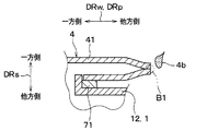
具体的には、図22に示すように、ロウ付けに際し、出口管4の扁平管部41の他方端411において扁平管部41の内周面にロウ材4bが塗布されると共に、その扁平管部41の他方端411はチューブ積層方向DRsに潰される。これによって、その扁平管部41の他方端411は閉塞される。そのように扁平管部41の他方端411が潰された上で一旦加熱されることにより、その他方端411は、その他方端411における扁平管部41の内周面のロウ付けで気密に塞がれる。例えば、図22のB1部分に塗布されたロウ材4bにより、扁平管部41の他方端411は気密に塞がれる。
Specifically, as shown in FIG. 22, at the time of brazing, the
なお、入口管5の扁平管部51の他方端511を塞ぐ方法も、上述した出口管4の扁平管部41の他方端411を塞ぐ方法と同様である。
The method of closing the other end 511 of the
以上説明したことを除き、本実施形態は第1実施形態と同様である。そして、本実施形態では、前述の第1実施形態と共通の構成から奏される効果を第1実施形態と同様に得ることができる。 Except as described above, this embodiment is the same as the first embodiment. Further, in the present embodiment, the effects obtained from the configuration common to the above-described first embodiment can be obtained in the same manner as the first embodiment.
(第6実施形態)
次に、第6実施形態について説明する。本実施形態では、前述の第1実施形態と異なる点を主として説明する。
(Sixth embodiment)
Next, a sixth embodiment will be described. In the present embodiment, points different from the first embodiment will be mainly described.
本実施形態では、出口管4および入口管5それぞれの扁平管部41、51の他方端411、511を塞ぐ方法が、第1実施形態に対して異なっている。本実施形態では、第1実施形態のキャップ6は用いられない。
In the present embodiment, a method of closing the other ends 411 and 511 of the
具体的には、図23に示すように、出口管4の扁平管部41の他方端411はチューブ積層方向DRsに潰され、これによって、その扁平管部41の他方端411は閉塞される。そのように扁平管部41の他方端411が潰された上で、その他方端411における扁平管部41の内周面が溶接される。これにより、その他方端411は気密に塞がれる。例えば、図23のB1部分が溶接されることにより、扁平管部41の他方端411は気密に塞がれる。
Specifically, as shown in FIG. 23, the
なお、入口管5の扁平管部51の他方端511を塞ぐ方法も、上述した出口管4の扁平管部41の他方端411を塞ぐ方法と同様である。
The method of closing the other end 511 of the
以上説明したことを除き、本実施形態は第1実施形態と同様である。そして、本実施形態では、前述の第1実施形態と共通の構成から奏される効果を第1実施形態と同様に得ることができる。 Except as described above, this embodiment is the same as the first embodiment. Further, in the present embodiment, the effects obtained from the configuration common to the above-described first embodiment can be obtained in the same manner as the first embodiment.
(他の実施形態)
(1)上述の各実施形態では図3に示すように、入口管5は出口管4に対しダクト方向DRdの一方側に配置されているが、逆に、出口管4が入口管5に対しダクト方向DRdの一方側に配置されていても差し支えない。
(Other embodiments)
(1) In each of the above embodiments, as shown in FIG. 3, the
(2)上述の各実施形態では図5に示すように、管延伸方向DRpはコア幅方向DRwに一致しているが、チューブ積層方向DRsとダクト方向DRdとに交差していれば、コア幅方向DRwに一致していなくてもよい。 (2) In each of the above-described embodiments, as shown in FIG. 5, the pipe extending direction DRp coincides with the core width direction DRw, but if the tube stacking direction DRs and the duct direction DRd intersect, the core width becomes smaller. It does not have to match the direction DRw.
(3)上述の各実施形態では図11に示すように、出口管4は積層部材7を介してダクト1にロウ付け接合されているが、その接合は、例えば溶接またはカシメなど、ロウ付け以外の接合方法で為されていることも想定される。更に言えば、積層部材7が設けられておらず、出口管4がダクト1に直接に接合されていることもに想定される。これらのことは、入口管5に関しても同様である。
(3) In each of the above-described embodiments, as shown in FIG. 11, the
(4)上述の各実施形態では図11に示すように、出口管4は積層部材7を介してダクト1にロウ付け接合され、そのロウ付け前の積層部材7としては、両面にロウ材がクラッドされたクラッド材が用いられるが、これは一例である。例えば、ロウ付け前の積層部材7として、出口管4側の面にだけロウ材がクラッドされたクラッド材が用いられ、且つ、ロウ付け前のダクト1の第2プレート12として、積層部材7側の面にだけロウ材がクラッドされたクラッド材が用いられてもよい。そのようにした場合には、その積層部材7にクラッドされたロウ材により、積層部材7と出口管4とが互いにロウ付け接合される。そして、その第2プレート12にクラッドされたロウ材により、第2プレート12と積層部材7とが互いにロウ付け接合される。
(4) In each of the above embodiments, as shown in FIG. 11, the
(5)上述の各実施形態では図11に示すように、ダクト1のダクト接合部126は、ダクト連通孔124aおよび接続凸部124をその全周にわたって取り囲むように設けられているが、これは一例である。例えば、そのダクト接合部126がダクト連通孔124aおよび接続凸部124をその全周にわたって取り囲んでいない構成も考え得る。このことは、もう一つのダクト接合部127についても同様である。
(5) In each of the above-described embodiments, as shown in FIG. 11, the
また、別の例として、ロウ付け前の出口管4として、積層部材7側の表面にロウ材がクラッドされたクラッド材が用いられ、且つ、ロウ付け前の積層部材7として、ダクト1の第2プレート12側の面にだけロウ材がクラッドされたクラッド材が用いられてもよい。そのようにした場合には、その出口管4にクラッドされたロウ材により、積層部材7と出口管4とが互いにロウ付け接合される。そして、その積層部材7にクラッドされたロウ材により、第2プレート12と積層部材7とが互いにロウ付け接合される。これらのことは、入口管5に関しても同様である。
Further, as another example, as the
(6)なお、本発明は、上述の実施形態に限定されることなく、種々変形して実施することができる。また、上記各実施形態において、実施形態を構成する要素は、特に必須であると明示した場合および原理的に明らかに必須であると考えられる場合等を除き、必ずしも必須のものではないことは言うまでもない。 (6) The present invention is not limited to the above-described embodiment, and can be implemented with various modifications. In each of the above embodiments, it is needless to say that elements constituting the embodiments are not necessarily essential, unless otherwise clearly indicated as being essential or in principle considered to be clearly essential. No.
また、上記各実施形態において、実施形態の構成要素の個数、数値、量、範囲等の数値が言及されている場合、特に必須であると明示した場合および原理的に明らかに特定の数に限定される場合等を除き、その特定の数に限定されるものではない。また、上記各実施形態において、構成要素等の材質、形状、位置関係等に言及するときは、特に明示した場合および原理的に特定の材質、形状、位置関係等に限定される場合等を除き、その材質、形状、位置関係等に限定されるものではない。 In each of the above embodiments, when a numerical value such as the number, numerical value, amount, range, or the like of the constituent elements of the exemplary embodiment is mentioned, it is particularly limited to a specific number when it is clearly stated that it is essential and in principle. The number is not limited to the specific number unless otherwise specified. Further, in each of the above embodiments, when referring to the material, shape, positional relationship, and the like of the constituent elements, unless otherwise specified, and in principle, it is limited to a specific material, shape, positional relationship, and the like. The material, shape, positional relationship, etc. are not limited.
(まとめ)
上記各実施形態の一部または全部で示された第1の観点によれば、インタークーラは、チューブ積層方向に積層された複数の冷却チューブを有する積層コアと、その積層コアに対しチューブ積層方向の一方側に配置され複数の冷却チューブへ連通する連通管とを備える。そして、複数の冷却チューブ内には、過給吸気と熱交換する冷却流体が流通する。連通管は、複数の冷却チューブへ接続される扁平管部を有し、その扁平管部は、チューブ積層方向と交差する方向へ拡がる扁平断面形状を成している。
(Summary)
According to a first aspect shown in a part or all of the above embodiments, an intercooler includes: a laminated core having a plurality of cooling tubes laminated in a tube laminating direction; And a communication pipe which is arranged on one side of the cooling pipe and communicates with the plurality of cooling tubes. The cooling fluid that exchanges heat with the supercharged intake air flows through the plurality of cooling tubes. The communication pipe has a flat tube portion connected to the plurality of cooling tubes, and the flat tube portion has a flat cross-sectional shape extending in a direction intersecting the tube stacking direction.
また、第2の観点によれば、扁平管部は、ダクトに対するチューブ積層方向の一方側に配置されると共に、そのダクトに接合される。そして、ダクトにはダクト連通孔が形成され、そのダクトは、扁平管部に接合されたダクト接合部をダクト連通孔の周りに有する。扁平管部は、ダクト連通孔を介して複数の冷却チューブへ連通している。従って、ダクトを設けると共に、連通管をダクトの表面に接合することが可能である。 According to the second aspect, the flat tube portion is arranged on one side in the tube stacking direction with respect to the duct, and is joined to the duct. A duct communication hole is formed in the duct, and the duct has a duct joint portion joined to the flat tube around the duct communication hole. The flat tube portion communicates with the plurality of cooling tubes via the duct communication hole. Therefore, it is possible to provide the duct and join the communication pipe to the surface of the duct.
また、第3の観点によれば、ダクト接合部は、積層板部が扁平管部とダクト接合部とのそれぞれに接合されることにより、積層板部を介して扁平管部に接合されている。そして、連通管のうち、積層部材の支持部に接合された管接合部は、扁平管部よりも管延伸方向の一方側に配置され、管先端部はその管接合部よりも管延伸方向の一方側に配置されている。従って、管延伸方向に延びる連通管を、積層部材によって補強することが可能である。 According to the third aspect, the duct joint portion is joined to the flat tube portion via the laminate plate portion by joining the laminate plate portion to each of the flat tube portion and the duct joint portion. . And, among the communicating pipes, the pipe joint part joined to the support part of the laminated member is arranged on one side in the pipe extending direction than the flat tube part, and the pipe tip part is in the pipe extending direction more than the pipe joint part. It is located on one side. Therefore, the communicating pipe extending in the pipe extending direction can be reinforced by the laminated member.
また、第4の観点によれば、扁平管部内に形成された流路の流路断面積は、管先端部内に形成された流路の流路断面積以上になっている。従って、扁平管部が扁平断面形状を成していることに起因した冷却流体の圧損を抑制することが可能である。 Further, according to the fourth aspect, the flow path cross-sectional area of the flow path formed in the flat tube portion is equal to or larger than the flow path cross-sectional area of the flow path formed in the pipe tip. Therefore, it is possible to suppress the pressure loss of the cooling fluid due to the flat tube portion having the flat cross-sectional shape.
また、第5の観点によれば、連通管に含まれる扁平管部の中心軸線は、管先端部の中心軸線に対しチューブ積層方向の一方側に位置している。従って、連通管の管先端部がインタークーラの幅をチューブ積層方向の一方側に拡大させることを抑制することが可能である。 Further, according to the fifth aspect, the center axis of the flat tube portion included in the communication tube is located on one side in the tube stacking direction with respect to the center axis of the tube tip. Therefore, it is possible to prevent the tube tip of the communication tube from expanding the width of the intercooler to one side in the tube stacking direction.
また、第6の観点によれば、ダクトは、ダクト通路に対し管延伸方向の一方側から面する一方側ダクト壁部を有する。そして、積層部材の支持部は、その一方側ダクト壁部よりも管延伸方向の一方側に位置している。従って、連通管の管先端部をダクトから管延伸方向の一方側へ突き出させることを可能としつつ、その連通管を積層部材で適切に支持することが可能である。 According to the sixth aspect, the duct has a one-side duct wall facing the duct passage from one side in the pipe extending direction. And the support part of a laminated member is located in one side of the pipe extending direction rather than the one side duct wall part. Accordingly, it is possible to appropriately support the communication pipe with the laminated member while allowing the pipe tip of the communication pipe to protrude from the duct to one side in the pipe extending direction.
また、第7の観点によれば、積層部材の支持部の先端は、連通管の突部に対し、管延伸方向の一方側とは反対側の他方側から突き当たっている。従って、連通管が曲げられるように撓むことを、その支持部の先端と連通管の突部との突当てによっても抑制することが可能である。 Further, according to the seventh aspect, the distal end of the support portion of the laminated member abuts against the protrusion of the communication pipe from the other side opposite to the one side in the pipe extending direction. Therefore, the bending of the communication pipe so as to be bent can also be suppressed by abutment between the distal end of the support portion and the projection of the communication pipe.
また、第8の観点によれば、ダクトは、チューブ積層方向に延びるフランジ部を、ダクト開口の周縁を形成するダクト端部に有し、そのフランジ部は、結合プレートの溝部の底を形成する壁部に接合されている。従って、ダクトと結合プレートとの接合部分を、ロウ付け時の積層コアの寸法変化を吸収可能な構造とすることができる。 According to the eighth aspect, the duct has a flange portion extending in the tube stacking direction at an end portion of the duct forming a peripheral edge of the duct opening, and the flange portion forms a bottom of the groove of the coupling plate. It is joined to the wall. Therefore, the joining portion between the duct and the coupling plate can have a structure capable of absorbing a dimensional change of the laminated core during brazing.
また、第9の観点によれば、結合プレートは、チューブ積層方向の一方側の端に一方側側縁を有し、連通管の全体は、その結合プレートの一方側側縁よりも、チューブ積層方向の一方側とは反対側の他方側に位置している。従って、連通管がチューブ積層方向の一方側へ突出することを回避することが可能である。 Further, according to the ninth aspect, the coupling plate has one side edge at one end in the tube laminating direction, and the entire communication pipe has a tube lamination higher than the one side edge of the coupling plate. It is located on the other side opposite to one side of the direction. Therefore, it is possible to prevent the communication pipe from protruding to one side in the tube stacking direction.
また、第10の観点によれば、インタークーラの製造方法において、管延伸方向がチューブ積層方向とダクト方向との各々に対して交差するように連通管を配置しつつ、ダクトに形成されたダクト連通孔を介して扁平管部を複数の冷却チューブへ連通させる。それと共に、積層板部に対するチューブ積層方向の一方側に扁平管部を積層配置し、且つ積層板部に対するチューブ積層方向の他方側に、ダクトのうちダクト連通孔の周りを構成するダクト接合部を積層配置する。その積層配置の後に、ダクトと連通管と積層部材とを一旦加熱することにより、ロウ材によって、積層板部を介して扁平管部をダクト接合部にロウ付けすると共に管接合部を支持部にロウ付けする。 According to the tenth aspect, in the method of manufacturing an intercooler, the duct formed in the duct is arranged while the communicating pipe is arranged so that the pipe extending direction intersects each of the tube stacking direction and the duct direction. The flat tube portion communicates with the plurality of cooling tubes via the communication hole. At the same time, a flat tube portion is laminated on one side in the tube laminating direction with respect to the laminated plate portion, and a duct joint portion forming around the duct communication hole of the duct is disposed on the other side in the tube laminating direction with respect to the laminated plate portion. Lay and arrange. After the stacking arrangement, the duct, the communication pipe, and the stacking member are once heated, so that the flat pipe section is brazed to the duct joint section via the laminated plate section by the brazing material, and the pipe joint section is formed into the support section. Braze.
2 積層コア
4 出口管(連通管)
41 出口管の扁平管部
5 入口管(連通管)
51 入口管の扁平管部
21 冷却チューブ
100 インタークーラ
105 エンジン(内燃機関)
SC 過給機
DRs チューブ積層方向
2
41 Flat tube part of
51 Flat tube part of
SC Turbocharger DRs Tube stacking direction
Claims (8)
チューブ積層方向(DRs)に積層された複数の冷却チューブ(21)を有する積層コア(2)と、
前記積層コアに対し前記チューブ積層方向の一方側に配置され、前記複数の冷却チューブへ連通する連通管(4、5)と、
前記過給吸気が流通するダクト通路(13)が形成され、該ダクト通路に前記積層コアを収容するダクト(1)と、
積層部材(7)とを備え、
前記複数の冷却チューブ内には、前記過給吸気と熱交換する冷却流体が流通し、
前記連通管は、前記複数の冷却チューブへ接続される扁平管部(41、51)を有し、
前記扁平管部は、前記チューブ積層方向と交差する方向へ拡がる扁平断面形状を成しており、前記ダクトに対する前記チューブ積層方向の前記一方側に配置されると共に、該ダクトに接合され、
前記ダクトにはダクト連通孔(124a、125a)が形成され、
該ダクトは、前記扁平管部に接合されたダクト接合部(126、127)を前記ダクト連通孔の周りに有し、
前記扁平管部は、前記ダクト連通孔を介して前記複数の冷却チューブへ連通しており、
前記積層部材は、前記扁平管部と前記ダクト接合部との間に配置され該扁平管部と該ダクト接合部とのそれぞれに対して積層された積層板部(71)と、該積層板部と一体構成された支持部(72)とを有し、
前記ダクトには、前記チューブ積層方向に交差するダクト方向(DRd)の一方側に設けられ前記過給吸気が流入する前記ダクト通路の流入口(13a)と、前記ダクト方向の他方側に設けられ前記過給吸気が流出する前記ダクト通路の流出口(13b)とが形成され、
前記連通管は、前記支持部に接合された管接合部(42、52)と、前記冷却流体を前記連通管へ流入させ又は前記冷却流体を前記連通管から流出させる外部配管部材(93、94)が接続される管先端部(44、54)とを有し、且つ、前記チューブ積層方向と前記ダクト方向とに交差する管延伸方向(DRp)に延びるように形成され、
前記ダクト接合部は、前記積層板部が前記扁平管部と前記ダクト接合部とのそれぞれに接合されることにより、前記積層板部を介して前記扁平管部に接合されており、
前記管接合部は前記扁平管部よりも前記管延伸方向の一方側に配置され、
前記管先端部は前記管接合部よりも前記管延伸方向の前記一方側に配置されているインタークーラ。 An intercooler for cooling supercharged intake air supplied to an internal combustion engine (105) via a supercharger (SC),
A laminated core (2) having a plurality of cooling tubes (21) laminated in a tube laminating direction (DRs);
A communication pipe (4, 5) arranged on one side in the tube stacking direction with respect to the stacked core and communicating with the plurality of cooling tubes ;
A duct (13) formed with a duct passage (13) through which the supercharged air flows, and a duct (1) accommodating the laminated core in the duct passage;
A laminated member (7) ,
In the plurality of cooling tubes, a cooling fluid that exchanges heat with the supercharged intake air flows,
The communication pipe has a flat pipe part (41, 51) connected to the plurality of cooling tubes,
The flat tube portion has a flat cross-sectional shape that extends in a direction intersecting with the tube stacking direction, and is arranged on the one side in the tube stacking direction with respect to the duct, and is joined to the duct,
Duct communication holes (124a, 125a) are formed in the duct,
The duct has a duct joint (126, 127) joined to the flat tube around the duct communication hole,
The flat tube portion communicates with the plurality of cooling tubes via the duct communication hole,
A laminated plate portion (71) disposed between the flat tube portion and the duct joint portion and laminated on each of the flat tube portion and the duct joint portion; And a support part (72) integrally formed,
The duct is provided on one side in a duct direction (DRd) intersecting with the tube stacking direction, and is provided on an inlet (13a) of the duct passage into which the supercharged intake air flows, and on the other side in the duct direction. An outlet (13b) of the duct passage through which the supercharged air flows out is formed;
The communication pipe includes a pipe connection part (42, 52) bonded to the support part and an external pipe member (93, 94) that allows the cooling fluid to flow into the communication pipe or the cooling fluid to flow out from the communication pipe. ) Is formed so as to have a pipe tip end (44, 54) to be connected, and to extend in a pipe extending direction (DRp) intersecting the tube laminating direction and the duct direction,
The duct joining portion is joined to the flat tube portion via the laminated plate portion by joining the laminated plate portion to each of the flat tube portion and the duct joining portion,
The pipe joint is disposed on one side in the pipe extending direction than the flat pipe,
An intercooler wherein the pipe tip is disposed on the one side in the pipe extending direction with respect to the pipe joint .
前記扁平管部の中心軸線(CLa)は、前記管先端部の中心軸線(CLb)に対し前記チューブ積層方向の前記一方側に位置している請求項1または2に記載のインタークーラ。 The flat tube portion and the tube tip each have a central axis (CLa, CLb) extending in the tube extending direction,
The flat tubes of the central axis (CLa), the tube tip intercooler according to claim 1 or 2 is located on the one side of the tube stacking direction with respect to the central axis (CLb) of.
前記支持部は、前記一方側ダクト壁部よりも前記管延伸方向の前記一方側に位置している請求項1ないし3のいずれか1つに記載のインタークーラ。 The duct has a one-sided duct wall (115) facing the duct passage from the one side in the pipe extending direction,
The intercooler according to any one of claims 1 to 3 , wherein the support portion is located on the one side in the pipe extending direction with respect to the one-side duct wall portion.
前記支持部は、前記管延伸方向の前記一方側に先端(721)を有し、
前記支持部の先端は、前記連通管の突部に対し、前記管延伸方向の前記一方側とは反対側の他方側から突き当たっている請求項1ないし4のいずれか1つに記載のインタークーラ。 The communication pipe has a protrusion (43, 53) that protrudes radially outward of the communication pipe,
The support portion has a tip (721) on the one side in the pipe extending direction,
The intercooler according to any one of claims 1 to 4 , wherein a tip of the support portion abuts on a protrusion of the communication pipe from the other side opposite to the one side in the pipe extending direction. .
前記ダクト開口は前記ダクト方向を向いて開口し、
前記ダクトは、前記チューブ積層方向に延びるフランジ部(123)を、前記ダクト開口の周縁を形成するダクト端部(123a)に有し、
前記フランジ部は、前記溝部の底を形成する壁部(32)に接合されている請求項1ないし5のいずれか1つに記載のインタークーラ。 A coupling plate (3) having a groove (33) extending along a periphery of the duct opening so as to surround the duct opening which is one of the inlet and the outlet, and joined to the duct; ,
The duct opening is open facing the duct direction,
The duct has a flange portion (123) extending in the tube stacking direction at a duct end portion (123a) forming a peripheral edge of the duct opening,
The intercooler according to any one of claims 1 to 5 , wherein the flange portion is joined to a wall (32) forming a bottom of the groove.
該結合プレートは、前記チューブ積層方向の前記一方側の端に一方側側縁(35a)を有し、
該結合プレートの一方側側縁は、前記ダクト接合部よりも前記チューブ積層方向の前記一方側に位置し、
前記連通管の全体は、前記結合プレートの一方側側縁よりも、前記チューブ積層方向の前記一方側とは反対側の他方側に位置している請求項1ないし5のいずれか1つに記載のインタークーラ。 A coupling plate (3) formed to surround a duct opening that is one of the inlet and the outlet;
The coupling plate has one side edge (35a) at the one end in the tube stacking direction,
One side edge of the coupling plate is located on the one side in the tube stacking direction than the duct joint,
Total of the communicating pipe, the than one side edge of the coupling plate, according to the said one side of the tube stacking direction any one of claims 1 located on the other side of the opposite side 5 Intercooler.
前記チューブ積層方向に交差するダクト方向(DRd)の一方側から他方側へと前記過給吸気が流通するダクト通路(13)が形成され、該ダクト通路に前記積層コアを収容するダクト(1)とを備えたインタークーラの製造方法であって、
前記ダクトを用意すること(S01)と、
扁平断面形状を成す扁平管部(41、51)と、該扁平管部よりも管延伸方向(DRp)の一方側に配置され外部配管部材(93、94)が接続される管先端部(44、54)と、前記管延伸方向で前記扁平管部と前記管先端部との間に配置された管接合部(42、52)とを有し、前記管延伸方向に延びるように形成された連通管(4、5)を用意すること(S01)と、
両面にロウ材を有する板材で構成され、積層板部(71)と該積層板部に一体構成された支持部(72)とを有する積層部材(7)を用意すること(S01)と、
前記管延伸方向が前記チューブ積層方向と前記ダクト方向との各々に対して交差するように前記連通管を配置しつつ、前記ダクトに形成されたダクト連通孔(124a、125a)を介して前記扁平管部を前記複数の冷却チューブへ連通させると共に、前記積層板部に対する前記チューブ積層方向の一方側に前記扁平管部を積層配置し、且つ前記積層板部に対する前記チューブ積層方向の他方側に、前記ダクトのうち前記ダクト連通孔の周りを構成するダクト接合部(126、127)を積層配置すること(S02)と、
前記積層配置の後に、前記ダクトと前記連通管と前記積層部材とを一旦加熱することにより、前記ロウ材によって、前記積層板部を介して前記扁平管部を前記ダクト接合部にロウ付けすると共に前記管接合部を前記支持部にロウ付けすること(S03)とを含むインタークーラの製造方法。 A cooling fluid that exchanges heat with supercharged intake air supplied to the internal combustion engine (105) through the supercharger (SC) flows and has a plurality of cooling tubes (21) stacked in the tube stacking direction (DRs). A laminated core (2) for cooling the supercharged air by heat exchange between the supercharged air and the cooling fluid;
A duct passage (13) through which the supercharged air flows is formed from one side to the other side in a duct direction (DRd) intersecting with the tube stacking direction, and a duct (1) accommodating the stacked core in the duct passage. A method of manufacturing an intercooler comprising:
Preparing the duct (S01);
A flat tube portion (41, 51) having a flat cross-sectional shape, and a tube tip portion (44) which is arranged on one side of the flat tube portion in the pipe extending direction (DRp) and is connected to an external pipe member (93, 94). , 54), and a pipe joint (42, 52) disposed between the flat pipe portion and the pipe tip in the pipe extension direction, and formed to extend in the pipe extension direction. Preparing communication pipes (4, 5) (S01);
Preparing a laminated member (7) composed of a plate material having a brazing material on both sides and having a laminated plate portion (71) and a support portion (72) integrally formed with the laminated plate portion (S01);
The flat tubes are arranged through duct communication holes (124a, 125a) formed in the duct while arranging the communication tubes such that the tube extending direction intersects the tube stacking direction and the duct direction, respectively. Along with communicating the tube portion to the plurality of cooling tubes, the flat tube portion is disposed on one side in the tube laminating direction with respect to the laminated plate portion, and on the other side in the tube laminating direction with respect to the laminated plate portion, Stacking and disposing duct joints (126, 127) around the duct communication hole in the duct (S02);
After the stacking arrangement, the duct, the communication pipe, and the stacking member are once heated, so that the flat tube portion is brazed to the duct joint portion via the laminate plate portion by the brazing material. Brazing the pipe joint to the support (S03).
Priority Applications (4)
| Application Number | Priority Date | Filing Date | Title |
|---|---|---|---|
| JP2016251185A JP6635022B2 (en) | 2016-12-26 | 2016-12-26 | Intercooler and method of manufacturing the intercooler |
| PCT/JP2017/041350 WO2018123332A1 (en) | 2016-12-26 | 2017-11-16 | Intercooler and method for manufacturing intercooler |
| DE112017006539.9T DE112017006539B4 (en) | 2016-12-26 | 2017-11-16 | Intercooler and manufacturing process for an intercooler |
| US16/449,494 US20190309675A1 (en) | 2016-12-26 | 2019-06-24 | Intercooler and method for manufacturing intercooler |
Applications Claiming Priority (1)
| Application Number | Priority Date | Filing Date | Title |
|---|---|---|---|
| JP2016251185A JP6635022B2 (en) | 2016-12-26 | 2016-12-26 | Intercooler and method of manufacturing the intercooler |
Publications (3)
| Publication Number | Publication Date |
|---|---|
| JP2018105192A JP2018105192A (en) | 2018-07-05 |
| JP2018105192A5 JP2018105192A5 (en) | 2019-02-28 |
| JP6635022B2 true JP6635022B2 (en) | 2020-01-22 |
Family
ID=62708044
Family Applications (1)
| Application Number | Title | Priority Date | Filing Date |
|---|---|---|---|
| JP2016251185A Expired - Fee Related JP6635022B2 (en) | 2016-12-26 | 2016-12-26 | Intercooler and method of manufacturing the intercooler |
Country Status (4)
| Country | Link |
|---|---|
| US (1) | US20190309675A1 (en) |
| JP (1) | JP6635022B2 (en) |
| DE (1) | DE112017006539B4 (en) |
| WO (1) | WO2018123332A1 (en) |
Families Citing this family (6)
| Publication number | Priority date | Publication date | Assignee | Title |
|---|---|---|---|---|
| SG11201805175VA (en) * | 2016-10-31 | 2018-07-30 | Yue Zhang | Metal plate having hollow tubes sandwiched therein and its use |
| USD912701S1 (en) * | 2018-09-12 | 2021-03-09 | Resource International Inc. | Transmission cooler for automotive applications |
| USD900161S1 (en) * | 2018-09-21 | 2020-10-27 | Resource International Inc. | Transmission cooler for automotive applications |
| USD907063S1 (en) * | 2018-09-27 | 2021-01-05 | Resource International Inc. | Air to water intercooler for automotive applications |
| USD905115S1 (en) * | 2018-10-09 | 2020-12-15 | Resource International Inc. | Transmission cooler for automotive applications |
| USD905116S1 (en) * | 2018-10-09 | 2020-12-15 | Resource International Inc. | Transmission cooler for automotive applications |
Family Cites Families (9)
| Publication number | Priority date | Publication date | Assignee | Title |
|---|---|---|---|---|
| JPH0645153Y2 (en) * | 1989-06-02 | 1994-11-16 | 昭和アルミニウム株式会社 | Stacked heat exchanger |
| US5964281A (en) * | 1996-07-31 | 1999-10-12 | Modine Manufacturing Company | Heat exchanger with adapter |
| JP3219125B2 (en) * | 1995-11-28 | 2001-10-15 | カルソニックカンセイ株式会社 | Radiator |
| DE102005010493A1 (en) | 2005-03-08 | 2006-09-14 | Modine Manufacturing Co., Racine | Heat exchanger with flat tubes and flat heat exchanger tube |
| FR2886391B1 (en) * | 2005-05-24 | 2014-01-03 | Valeo Systemes Thermiques | HEAT EXCHANGER HAVING A HEAT EXCHANGE BEAM IN A HOUSING |
| DE102013200448A1 (en) | 2013-01-15 | 2014-07-17 | Bayerische Motoren Werke Aktiengesellschaft | Cooling device, in particular for battery modules, and vehicle, comprising such a cooling device |
| CA2962700A1 (en) * | 2014-10-03 | 2016-04-07 | Dana Canada Corporation | Heat exchanger with self-retaining bypass seal |
| DE102016001391A1 (en) * | 2015-02-23 | 2016-08-25 | Modine Manufacturing Company | HEAT EXCHANGER FOR COOLING ELOZE FLOATING OF DAMAGED AIR USING ANY FLUID COOLANT |
| CN107407537B (en) | 2015-03-02 | 2019-04-23 | 株式会社电装 | Heat exchanger |
-
2016
- 2016-12-26 JP JP2016251185A patent/JP6635022B2/en not_active Expired - Fee Related
-
2017
- 2017-11-16 WO PCT/JP2017/041350 patent/WO2018123332A1/en active Application Filing
- 2017-11-16 DE DE112017006539.9T patent/DE112017006539B4/en not_active Expired - Fee Related
-
2019
- 2019-06-24 US US16/449,494 patent/US20190309675A1/en not_active Abandoned
Also Published As
| Publication number | Publication date |
|---|---|
| DE112017006539B4 (en) | 2021-12-30 |
| WO2018123332A1 (en) | 2018-07-05 |
| US20190309675A1 (en) | 2019-10-10 |
| DE112017006539T5 (en) | 2019-09-12 |
| JP2018105192A (en) | 2018-07-05 |
Similar Documents
| Publication | Publication Date | Title |
|---|---|---|
| JP6635022B2 (en) | Intercooler and method of manufacturing the intercooler | |
| CN104011494B (en) | Exhaust heat exchanger | |
| CN106917667B (en) | Indirect intercooler | |
| US10508865B2 (en) | Heat exchanger | |
| WO2014021026A1 (en) | Heat exchanger | |
| US20150129186A1 (en) | Heat Exchanger Having A Reinforced Collector | |
| JP6601384B2 (en) | Intercooler | |
| JP2008170140A (en) | Heat exchanger for vehicle | |
| JP4690883B2 (en) | Heat exchanger and air conditioner | |
| WO2014103639A1 (en) | Compound heat exchanger | |
| US20050274504A1 (en) | Heat exchanger having projecting fluid passage | |
| JP2014055758A (en) | Compound heat exchanger | |
| JP2010007629A (en) | Heat exchanger for vehicle | |
| WO2018123335A1 (en) | Intercooler | |
| KR101971483B1 (en) | Heater | |
| JP2007278557A (en) | Heat exchanger | |
| JP6566142B2 (en) | Heat exchanger | |
| JP3812021B2 (en) | Laminate heat exchanger | |
| JP4276893B2 (en) | Vehicle heat exchange device | |
| US20170010056A1 (en) | Heat exchanger | |
| WO2018173536A1 (en) | Heat exchanger | |
| JP2000304489A (en) | Heat exchanger and heat radiator | |
| JP2004044920A (en) | Tank for heat exchanger | |
| WO2018037897A1 (en) | Cooling device | |
| JPH09287887A (en) | Combined heat-exchanger |
Legal Events
| Date | Code | Title | Description |
|---|---|---|---|
| A521 | Request for written amendment filed |
Free format text: JAPANESE INTERMEDIATE CODE: A523 Effective date: 20190114 |
|
| A621 | Written request for application examination |
Free format text: JAPANESE INTERMEDIATE CODE: A621 Effective date: 20190114 |
|
| TRDD | Decision of grant or rejection written | ||
| A01 | Written decision to grant a patent or to grant a registration (utility model) |
Free format text: JAPANESE INTERMEDIATE CODE: A01 Effective date: 20191119 |
|
| A61 | First payment of annual fees (during grant procedure) |
Free format text: JAPANESE INTERMEDIATE CODE: A61 Effective date: 20191202 |
|
| R151 | Written notification of patent or utility model registration |
Ref document number: 6635022 Country of ref document: JP Free format text: JAPANESE INTERMEDIATE CODE: R151 |
|
| LAPS | Cancellation because of no payment of annual fees |