JP6781031B2 - Substrate processing method and heat treatment equipment - Google Patents
Substrate processing method and heat treatment equipment Download PDFInfo
- Publication number
- JP6781031B2 JP6781031B2 JP2016238138A JP2016238138A JP6781031B2 JP 6781031 B2 JP6781031 B2 JP 6781031B2 JP 2016238138 A JP2016238138 A JP 2016238138A JP 2016238138 A JP2016238138 A JP 2016238138A JP 6781031 B2 JP6781031 B2 JP 6781031B2
- Authority
- JP
- Japan
- Prior art keywords
- processing chamber
- heat treatment
- water
- outer peripheral
- substrate
- Prior art date
- Legal status (The legal status is an assumption and is not a legal conclusion. Google has not performed a legal analysis and makes no representation as to the accuracy of the status listed.)
- Active
Links
- 238000010438 heat treatment Methods 0.000 title claims description 204
- 239000000758 substrate Substances 0.000 title claims description 73
- 238000003672 processing method Methods 0.000 title claims description 18
- 238000012545 processing Methods 0.000 claims description 302
- XLYOFNOQVPJJNP-UHFFFAOYSA-N water Substances O XLYOFNOQVPJJNP-UHFFFAOYSA-N 0.000 claims description 224
- 229910052751 metal Inorganic materials 0.000 claims description 193
- 239000002184 metal Substances 0.000 claims description 193
- 230000002093 peripheral effect Effects 0.000 claims description 106
- 239000000463 material Substances 0.000 claims description 44
- 230000003028 elevating effect Effects 0.000 claims description 42
- 238000000034 method Methods 0.000 claims description 13
- 230000008569 process Effects 0.000 claims description 12
- 238000006073 displacement reaction Methods 0.000 claims description 11
- 238000007599 discharging Methods 0.000 claims 1
- 235000012431 wafers Nutrition 0.000 description 190
- 238000012546 transfer Methods 0.000 description 67
- 238000006243 chemical reaction Methods 0.000 description 29
- 230000004520 agglutination Effects 0.000 description 24
- 238000011109 contamination Methods 0.000 description 19
- 238000000576 coating method Methods 0.000 description 17
- 239000011248 coating agent Substances 0.000 description 16
- 239000007788 liquid Substances 0.000 description 10
- 239000004065 semiconductor Substances 0.000 description 8
- 238000004140 cleaning Methods 0.000 description 5
- 230000007547 defect Effects 0.000 description 5
- 238000011161 development Methods 0.000 description 5
- 230000007246 mechanism Effects 0.000 description 5
- 230000000694 effects Effects 0.000 description 4
- 230000002209 hydrophobic effect Effects 0.000 description 4
- 230000035945 sensitivity Effects 0.000 description 4
- 238000001039 wet etching Methods 0.000 description 4
- 238000004220 aggregation Methods 0.000 description 3
- 230000002776 aggregation Effects 0.000 description 3
- 238000010586 diagram Methods 0.000 description 3
- 239000003446 ligand Substances 0.000 description 3
- 150000002739 metals Chemical class 0.000 description 3
- 230000002238 attenuated effect Effects 0.000 description 2
- 238000004519 manufacturing process Methods 0.000 description 2
- 238000012986 modification Methods 0.000 description 2
- 230000004048 modification Effects 0.000 description 2
- 238000000206 photolithography Methods 0.000 description 2
- 238000004528 spin coating Methods 0.000 description 2
- 238000003860 storage Methods 0.000 description 2
- ATJFFYVFTNAWJD-UHFFFAOYSA-N Tin Chemical compound [Sn] ATJFFYVFTNAWJD-UHFFFAOYSA-N 0.000 description 1
- RTAQQCXQSZGOHL-UHFFFAOYSA-N Titanium Chemical compound [Ti] RTAQQCXQSZGOHL-UHFFFAOYSA-N 0.000 description 1
- QCWXUUIWCKQGHC-UHFFFAOYSA-N Zirconium Chemical compound [Zr] QCWXUUIWCKQGHC-UHFFFAOYSA-N 0.000 description 1
- 238000001816 cooling Methods 0.000 description 1
- 239000000498 cooling water Substances 0.000 description 1
- 150000004696 coordination complex Chemical class 0.000 description 1
- 238000005530 etching Methods 0.000 description 1
- 230000006872 improvement Effects 0.000 description 1
- 230000010354 integration Effects 0.000 description 1
- 230000002452 interceptive effect Effects 0.000 description 1
- 238000012423 maintenance Methods 0.000 description 1
- 239000012528 membrane Substances 0.000 description 1
- 229910044991 metal oxide Inorganic materials 0.000 description 1
- 150000004706 metal oxides Chemical class 0.000 description 1
- 239000003595 mist Substances 0.000 description 1
- 230000003287 optical effect Effects 0.000 description 1
- 238000011084 recovery Methods 0.000 description 1
- 239000008400 supply water Substances 0.000 description 1
- 230000001629 suppression Effects 0.000 description 1
- 229910052719 titanium Inorganic materials 0.000 description 1
- 239000010936 titanium Substances 0.000 description 1
- 229910052726 zirconium Inorganic materials 0.000 description 1
Images


Classifications
-
- H—ELECTRICITY
- H01—ELECTRIC ELEMENTS
- H01L—SEMICONDUCTOR DEVICES NOT COVERED BY CLASS H10
- H01L21/00—Processes or apparatus adapted for the manufacture or treatment of semiconductor or solid state devices or of parts thereof
- H01L21/02—Manufacture or treatment of semiconductor devices or of parts thereof
- H01L21/027—Making masks on semiconductor bodies for further photolithographic processing not provided for in group H01L21/18 or H01L21/34
- H01L21/0271—Making masks on semiconductor bodies for further photolithographic processing not provided for in group H01L21/18 or H01L21/34 comprising organic layers
- H01L21/0273—Making masks on semiconductor bodies for further photolithographic processing not provided for in group H01L21/18 or H01L21/34 comprising organic layers characterised by the treatment of photoresist layers
- H01L21/0274—Photolithographic processes
-
- G—PHYSICS
- G03—PHOTOGRAPHY; CINEMATOGRAPHY; ANALOGOUS TECHNIQUES USING WAVES OTHER THAN OPTICAL WAVES; ELECTROGRAPHY; HOLOGRAPHY
- G03F—PHOTOMECHANICAL PRODUCTION OF TEXTURED OR PATTERNED SURFACES, e.g. FOR PRINTING, FOR PROCESSING OF SEMICONDUCTOR DEVICES; MATERIALS THEREFOR; ORIGINALS THEREFOR; APPARATUS SPECIALLY ADAPTED THEREFOR
- G03F7/00—Photomechanical, e.g. photolithographic, production of textured or patterned surfaces, e.g. printing surfaces; Materials therefor, e.g. comprising photoresists; Apparatus specially adapted therefor
- G03F7/004—Photosensitive materials
- G03F7/0042—Photosensitive materials with inorganic or organometallic light-sensitive compounds not otherwise provided for, e.g. inorganic resists
- G03F7/0043—Chalcogenides; Silicon, germanium, arsenic or derivatives thereof; Metals, oxides or alloys thereof
-
- G—PHYSICS
- G03—PHOTOGRAPHY; CINEMATOGRAPHY; ANALOGOUS TECHNIQUES USING WAVES OTHER THAN OPTICAL WAVES; ELECTROGRAPHY; HOLOGRAPHY
- G03F—PHOTOMECHANICAL PRODUCTION OF TEXTURED OR PATTERNED SURFACES, e.g. FOR PRINTING, FOR PROCESSING OF SEMICONDUCTOR DEVICES; MATERIALS THEREFOR; ORIGINALS THEREFOR; APPARATUS SPECIALLY ADAPTED THEREFOR
- G03F7/00—Photomechanical, e.g. photolithographic, production of textured or patterned surfaces, e.g. printing surfaces; Materials therefor, e.g. comprising photoresists; Apparatus specially adapted therefor
- G03F7/26—Processing photosensitive materials; Apparatus therefor
- G03F7/38—Treatment before imagewise removal, e.g. prebaking
-
- H—ELECTRICITY
- H01—ELECTRIC ELEMENTS
- H01L—SEMICONDUCTOR DEVICES NOT COVERED BY CLASS H10
- H01L21/00—Processes or apparatus adapted for the manufacture or treatment of semiconductor or solid state devices or of parts thereof
- H01L21/02—Manufacture or treatment of semiconductor devices or of parts thereof
- H01L21/027—Making masks on semiconductor bodies for further photolithographic processing not provided for in group H01L21/18 or H01L21/34
- H01L21/0271—Making masks on semiconductor bodies for further photolithographic processing not provided for in group H01L21/18 or H01L21/34 comprising organic layers
- H01L21/0273—Making masks on semiconductor bodies for further photolithographic processing not provided for in group H01L21/18 or H01L21/34 comprising organic layers characterised by the treatment of photoresist layers
-
- H—ELECTRICITY
- H01—ELECTRIC ELEMENTS
- H01L—SEMICONDUCTOR DEVICES NOT COVERED BY CLASS H10
- H01L21/00—Processes or apparatus adapted for the manufacture or treatment of semiconductor or solid state devices or of parts thereof
- H01L21/02—Manufacture or treatment of semiconductor devices or of parts thereof
- H01L21/04—Manufacture or treatment of semiconductor devices or of parts thereof the devices having at least one potential-jump barrier or surface barrier, e.g. PN junction, depletion layer or carrier concentration layer
- H01L21/18—Manufacture or treatment of semiconductor devices or of parts thereof the devices having at least one potential-jump barrier or surface barrier, e.g. PN junction, depletion layer or carrier concentration layer the devices having semiconductor bodies comprising elements of Group IV of the Periodic System or AIIIBV compounds with or without impurities, e.g. doping materials
- H01L21/30—Treatment of semiconductor bodies using processes or apparatus not provided for in groups H01L21/20 - H01L21/26
- H01L21/31—Treatment of semiconductor bodies using processes or apparatus not provided for in groups H01L21/20 - H01L21/26 to form insulating layers thereon, e.g. for masking or by using photolithographic techniques; After treatment of these layers; Selection of materials for these layers
- H01L21/3105—After-treatment
- H01L21/31058—After-treatment of organic layers
-
- H—ELECTRICITY
- H01—ELECTRIC ELEMENTS
- H01L—SEMICONDUCTOR DEVICES NOT COVERED BY CLASS H10
- H01L21/00—Processes or apparatus adapted for the manufacture or treatment of semiconductor or solid state devices or of parts thereof
- H01L21/67—Apparatus specially adapted for handling semiconductor or electric solid state devices during manufacture or treatment thereof; Apparatus specially adapted for handling wafers during manufacture or treatment of semiconductor or electric solid state devices or components ; Apparatus not specifically provided for elsewhere
- H01L21/67005—Apparatus not specifically provided for elsewhere
- H01L21/67011—Apparatus for manufacture or treatment
- H01L21/67017—Apparatus for fluid treatment
-
- H—ELECTRICITY
- H01—ELECTRIC ELEMENTS
- H01L—SEMICONDUCTOR DEVICES NOT COVERED BY CLASS H10
- H01L21/00—Processes or apparatus adapted for the manufacture or treatment of semiconductor or solid state devices or of parts thereof
- H01L21/67—Apparatus specially adapted for handling semiconductor or electric solid state devices during manufacture or treatment thereof; Apparatus specially adapted for handling wafers during manufacture or treatment of semiconductor or electric solid state devices or components ; Apparatus not specifically provided for elsewhere
- H01L21/67005—Apparatus not specifically provided for elsewhere
- H01L21/67011—Apparatus for manufacture or treatment
- H01L21/67098—Apparatus for thermal treatment
- H01L21/67103—Apparatus for thermal treatment mainly by conduction
-
- H—ELECTRICITY
- H01—ELECTRIC ELEMENTS
- H01L—SEMICONDUCTOR DEVICES NOT COVERED BY CLASS H10
- H01L21/00—Processes or apparatus adapted for the manufacture or treatment of semiconductor or solid state devices or of parts thereof
- H01L21/67—Apparatus specially adapted for handling semiconductor or electric solid state devices during manufacture or treatment thereof; Apparatus specially adapted for handling wafers during manufacture or treatment of semiconductor or electric solid state devices or components ; Apparatus not specifically provided for elsewhere
- H01L21/67005—Apparatus not specifically provided for elsewhere
- H01L21/67011—Apparatus for manufacture or treatment
- H01L21/67155—Apparatus for manufacturing or treating in a plurality of work-stations
- H01L21/6719—Apparatus for manufacturing or treating in a plurality of work-stations characterized by the construction of the processing chambers, e.g. modular processing chambers
Description
本発明は、基板に形成された金属含有膜を熱処理する基板処理方法及び熱処理装置に関する。 The present invention relates to a substrate processing method and a heat treatment apparatus for heat-treating a metal-containing film formed on a substrate.
例えば半導体デバイスの製造プロセスにおけるフォトリソグラフィー工程では、例えば半導体ウェハ(以下、「ウェハ」という。)上にレジスト液を塗布してレジスト膜を形成するレジスト塗布処理、当該レジスト膜を所定のパターンを露光する露光処理、露光後にレジスト膜の化学反応を促進させるために加熱するポストエクスポージャーベーキング処理(以下、「PEB処理」という。)、露光されたレジスト膜を現像する現像処理などが順次行われ、ウェハ上に所定のレジストパターンが形成される。 For example, in a photolithography process in a semiconductor device manufacturing process, for example, a resist coating process in which a resist solution is applied onto a semiconductor wafer (hereinafter referred to as “wafer”) to form a resist film, and the resist film is exposed to a predetermined pattern. The exposure process, the post-exposure baking process (hereinafter referred to as "PEB process") that heats the resist film after exposure to accelerate the chemical reaction, and the development process that develops the exposed resist film are performed in sequence, and the wafer is subjected to A predetermined resist pattern is formed on the top.
ところで近年、半導体デバイスのさらなる高集積化に伴い、レジストパターンの微細化が求められている。そこで、レジストパターンの微細化を実現するため、EUV(Extreme Ultraviolet;極端紫外)光を用いた露光処理が提案されている。また、EUVに用いられるレジストとして、高解像性や高エッチング耐性、また露光に対する高感度の特徴から、金属を含有するレジスト(以下、「金属含有レジスト」という。)が提案されている(特許文献1)。 By the way, in recent years, with the further increase in integration of semiconductor devices, miniaturization of resist patterns has been required. Therefore, in order to realize the miniaturization of the resist pattern, an exposure process using EUV (Extreme Ultraviolet) light has been proposed. Further, as a resist used for EUV, a metal-containing resist (hereinafter referred to as "metal-containing resist") has been proposed because of its high resolution, high etching resistance, and high sensitivity to exposure (patented). Document 1).
半導体デバイスの製造プロセスにおいて、金属は電気特性に大きく関与することから、厳格に管理されている。この点、金属含有レジストに対するPEB処理では、金属含有昇華物が発生するため、高排気により当該金属含有昇華物を回収し、金属汚染を抑制する必要がある。特に金属含有レジストを用いた場合の金属含有昇華物は分子レベルの小さいものであり、金属による汚染は半導体デバイスの電気特性に影響を与える。 In the manufacturing process of semiconductor devices, metals are strictly controlled because they play a major role in electrical properties. In this respect, in the PEB treatment on the metal-containing resist, a metal-containing sublimated product is generated. Therefore, it is necessary to recover the metal-containing sublimated product by high exhaust gas and suppress metal contamination. In particular, when a metal-containing resist is used, the metal-containing sublimated product has a small molecular level, and contamination by metal affects the electrical properties of the semiconductor device.
一方、現状のPEB処理において高排気を行うと、湿度管理されていない外気が処理チャンバ内に流入する。本発明者らが鋭意検討したところ、金属含有レジストは水分に対して感度が高く、所定範囲外の湿度の処理雰囲気下では、レジストパターンの寸法(例えば線幅)の均一性が悪化することが分かった。 On the other hand, when high exhaust is performed in the current PEB treatment, outside air whose humidity is not controlled flows into the treatment chamber. As a result of diligent studies by the present inventors, the metal-containing resist is highly sensitive to moisture, and the uniformity of the resist pattern dimensions (for example, line width) may deteriorate in a treatment atmosphere of humidity outside a predetermined range. Do you get it.
以上のように、金属含有レジストに対するPEB処理において、金属汚染の抑制とレジストパターン寸法の均一性を両立させるには、改善の余地がある。 As described above, in the PEB treatment for a metal-containing resist, there is room for improvement in order to achieve both suppression of metal contamination and uniformity of resist pattern dimensions.
本発明は、かかる点に鑑みてなされたものであり、金属含有材料を用いた基板処理において、熱処理中の金属汚染を抑制しつつ、金属含有膜を適切に形成することを目的とする。 The present invention has been made in view of this point, and an object of the present invention is to appropriately form a metal-containing film while suppressing metal contamination during heat treatment in a substrate treatment using a metal-containing material.
前記の目的を達成するため、本発明は、基板に形成された金属含有膜に水分を供給して熱処理する基板処理方法であって、前記熱処理は、処理チャンバの内部に設けられた熱処理板に基板を載置した状態で、前記処理チャンバの内部に水分含有ガスを供給すると共に、前記処理チャンバの外周部から当該処理チャンバの内部を第1の排気量で排気する第1の工程と、その後、前記水分含有ガスの供給を停止し、前記処理チャンバの中央部から当該処理チャンバの内部を、前記第1の排気量よりも大きい第2の排気量で排気する第2の工程と、を有することを特徴としている。
In order to achieve the above object, the present invention is a substrate treatment method in which water is supplied to a metal-containing film formed on the substrate to heat the treatment, and the heat treatment is performed on a heat treatment plate provided inside the treatment chamber. A first step of supplying a moisture-containing gas to the inside of the processing chamber with the substrate mounted and exhausting the inside of the processing chamber from the outer peripheral portion of the processing chamber with a first exhaust amount . After that, a second step of stopping the supply of the water-containing gas and exhausting the inside of the processing chamber from the central portion of the processing chamber with a second exhaust amount larger than the first exhaust amount. It is characterized by having.
本発明によれば、熱処理を行う際、金属含有膜には水分が供給されている。この水分供給は熱処理前に行われてもよいし、熱処理中に行われてもよく、熱処理中に適量の水分が金属含有膜に供給されていればよい。そうすると、例えば金属含有膜が金属含有レジスト膜の場合、レジストパターンの寸法を均一にすることができる。また、熱処理中に処理チャンバの内部を排気しているので、当該熱処理中に発生する金属含有昇華物を回収することができ、金属汚染を抑制して、半導体デバイスの欠陥を抑制することができる。 According to the present invention, water is supplied to the metal-containing film when the heat treatment is performed. This water supply may be performed before the heat treatment or during the heat treatment, and an appropriate amount of water may be supplied to the metal-containing membrane during the heat treatment. Then, for example, when the metal-containing film is a metal-containing resist film, the size of the resist pattern can be made uniform. Further, since the inside of the processing chamber is exhausted during the heat treatment, the metal-containing sublimated material generated during the heat treatment can be recovered, metal contamination can be suppressed, and defects of the semiconductor device can be suppressed. ..
前記処理チャンバの内部であって前記熱処理板に対向する位置には、下面に複数のガス供給孔が形成されたシャワーヘッドが設けられ、前記第1の工程において、前記シャワーヘッドから前記処理チャンバの内部に前記水分含有ガスが供給されてもよい。 A shower head having a plurality of gas supply holes formed on the lower surface thereof is provided inside the processing chamber at a position facing the heat treatment plate, and in the first step, the shower head is connected to the processing chamber. The water-containing gas may be supplied to the inside.
前記処理チャンバは、昇降自在の上部チャンバと、前記上部チャンバと一体となって内部を密閉可能な下部チャンバと、を有し、前記第2の工程において、前記上部チャンバを上昇させ、前記処理チャンバの外周部から内部に外気を流入させると共に、前記処理チャンバの中央部から当該処理チャンバの内部を排気してもよい。 The processing chamber has an upper chamber that can be raised and lowered and a lower chamber that can be integrally sealed inside with the upper chamber. In the second step, the upper chamber is raised and the processing chamber is raised. The outside air may be allowed to flow into the inside from the outer peripheral portion of the processing chamber, and the inside of the processing chamber may be exhausted from the central portion of the processing chamber.
前記基板処理方法は、前記第1の工程後であって前記第2の工程前に、前記水分含有ガスの供給を停止し、前記処理チャンバの外周部から当該処理チャンバの内部を前記第1の排気量で排気する工程をさらに有していてもよい。 In the substrate processing method, after the first step and before the second step, the supply of the water-containing gas is stopped, and the inside of the processing chamber is viewed from the outer peripheral portion of the processing chamber. It may further have a step of exhausting by the displacement.
前記基板処理方法は、前記第2の工程後に、前記熱処理板から基板を上昇させ、前記水分含有ガスの供給を停止し、前記処理チャンバの中央部から当該処理チャンバの内部を前記第2の排気量で排気する工程をさらに有していてもよい。 In the substrate processing method, after the second step, the substrate is raised from the heat treatment plate, the supply of the water-containing gas is stopped, and the inside of the processing chamber is exhausted from the central portion of the processing chamber. It may further have a step of exhausting by volume.
また、前記熱処理において、前記熱処理板に基板を載置した状態で、前記処理チャンバの外周部に環状に設けられた水分供給部から、当該処理チャンバの内部に水分含有ガスを供給すると共に、前記処理チャンバの上面中央部に設けられた中央排気部から、当該処理チャンバの内部を排気してもよい。 Further, in the heat treatment, with the substrate placed on the heat treatment plate, a water-containing gas is supplied to the inside of the treatment chamber from a water supply unit provided in an annular shape on the outer peripheral portion of the treatment chamber, and the heat treatment chamber is described. The inside of the processing chamber may be exhausted from the central exhaust portion provided at the center of the upper surface of the processing chamber.
前記水分供給部には、当該水分供給部の周上に等間隔で複数のガス供給孔が形成され、前記複数のガス供給孔から前記処理チャンバの内部に、前記水分含有ガスが供給されてもよい。 In the water supply unit, a plurality of gas supply holes are formed at equal intervals on the circumference of the water supply unit, and even if the water-containing gas is supplied to the inside of the processing chamber from the plurality of gas supply holes. Good.
前記処理チャンバの外周部において前記水分供給部より内側には、環状のガス流通部が設けられ、前記ガス流通部には、当該ガス流通部の周上に等間隔で複数のガス流通孔が形成され、前記水分供給部から供給された前記水分含有ガスは、前記複数のガス流通孔を通って前記処理チャンバの内部に供給されてもよい。 An annular gas flow section is provided inside the water supply section on the outer peripheral portion of the processing chamber, and a plurality of gas flow holes are formed at equal intervals on the circumference of the gas flow section in the gas flow section. The water-containing gas supplied from the water supply unit may be supplied to the inside of the processing chamber through the plurality of gas flow holes.
また、前記基板処理方法では、基板に金属含有材料を塗布して前記金属含有膜を形成し、さらに前記金属含有膜を露光した後、当該金属含有膜を熱処理し、前記熱処理前又は前記熱処理中に、前記金属含有膜に水を供給してもよい。 Further, in the substrate processing method, a metal-containing material is applied to a substrate to form the metal-containing film, and after the metal-containing film is exposed, the metal-containing film is heat-treated before or during the heat treatment. In addition, water may be supplied to the metal-containing film.
また、前記処理チャンバの外周部には、当該処理チャンバを開閉する開閉シャッタが設けられ、前記熱処理は、前記開閉シャッタによって前記処理チャンバを閉じ、前記熱処理板に基板を載置した状態で、前記処理チャンバの内部に水分含有ガスを供給すると共に、前記処理チャンバの外周部から当該処理チャンバの内部を排気する第1の工程と、その後、前記熱処理板から基板を上昇させ、前記水分含有ガスの供給を停止し、前記処理チャンバの中央部から当該処理チャンバの内部を排気する第2の工程と、その後、前記開閉シャッタによって前記処理チャンバを開ける第3の工程と、を有していてもよい。 Further, an opening / closing shutter for opening / closing the processing chamber is provided on the outer peripheral portion of the processing chamber, and in the heat treatment, the processing chamber is closed by the opening / closing shutter, and the substrate is placed on the heat treatment plate. A first step of supplying a moisture-containing gas to the inside of the processing chamber and exhausting the inside of the processing chamber from the outer periphery of the processing chamber, and then raising the substrate from the heat treatment plate to raise the moisture-containing gas. It may have a second step of stopping the supply and exhausting the inside of the processing chamber from the central portion of the processing chamber, and then a third step of opening the processing chamber by the opening / closing shutter. ..
前記熱処理において、前記処理チャンバの外周部に鉛直方向且つ環状に気流を形成してもよい。 In the heat treatment, an air flow may be formed in a vertical direction and in an annular shape on the outer peripheral portion of the processing chamber.
別な観点による本発明は、基板に形成された金属含有膜を熱処理する熱処理装置であって、基板を収容する処理チャンバと、前記処理チャンバの内部に設けられ、基板を載置する熱処理板と、前記金属含有膜に水分を供給する水分供給部と、前記処理チャンバの中央部から当該処理チャンバの内部を排気する中央排気部と、前記処理チャンバの外周部から当該処理チャンバの内部を排気する外周排気部と、前記処理チャンバ、前記熱処理板、前記水分供給部、前記中央排気部及び前記外周排気部の動作を制御する制御部と、を有し、前記水分供給部は、前記処理チャンバの内部に水分含有ガスを供給し、前記制御部は、前記熱処理板に基板を載置した状態で、前記水分供給部から前記処理チャンバの内部に前記水分含有ガスを供給すると共に、前記外周排気部によって前記処理チャンバの外周部から当該処理チャンバの内部を第1の排気量で排気する第1の工程と、その後、前記水分供給部からの前記水分含有ガスの供給を停止し、前記中央排気部によって前記処理チャンバの中央部から当該処理チャンバの内部を、前記第1の排気量よりも大きい第2の排気量で排気する第2の工程と、を実行するように、前記熱処理板、前記水分供給部、前記中央排気部及び前記外周排気部の動作を制御することを特徴としている。
From another point of view, the present invention is a heat treatment apparatus for heat-treating a metal-containing film formed on a substrate, a processing chamber for accommodating the substrate, and a heat treatment plate provided inside the processing chamber on which the substrate is placed. A water supply unit that supplies water to the metal-containing film, a central exhaust unit that exhausts the inside of the processing chamber from the central portion of the processing chamber, and an outer peripheral portion of the processing chamber that exhausts the inside of the processing chamber. and the outer peripheral exhaust unit, said processing chamber, said thermal processing plate, wherein the moisture supply section, have a, and a control unit for controlling the operation of the central exhaust portion and the outer peripheral exhaust unit, the water supply unit of said processing chamber The water-containing gas is supplied to the inside, and the control unit supplies the water-containing gas from the water supply unit to the inside of the processing chamber in a state where the substrate is placed on the heat treatment plate, and at the same time, the outer peripheral exhaust unit. A first step of exhausting the inside of the processing chamber from the outer peripheral portion of the processing chamber with a first exhaust amount, and then stopping the supply of the water-containing gas from the water supply unit and the central exhaust unit. The heat treatment plate, the water content, so as to execute a second step of exhausting the inside of the processing chamber from the central portion of the processing chamber with a second exhaust amount larger than the first exhaust amount. It is characterized in that the operation of the supply unit, the central exhaust unit, and the outer peripheral exhaust unit is controlled .
前記水分供給部は、前記処理チャンバの内部であって前記熱処理板に対向する位置に設けられたシャワーヘッドであって、前記シャワーヘッドの下面には、複数のガス供給孔が形成されていてもよい。 The water supply unit is a shower head provided inside the processing chamber at a position facing the heat treatment plate, and even if a plurality of gas supply holes are formed on the lower surface of the shower head. Good.
前記処理チャンバは、昇降自在の上部チャンバと、前記上部チャンバと一体となって内部を密閉可能な下部チャンバと、を有し、前記制御部は、前記第2の工程において、前記上部チャンバを上昇させ、前記処理チャンバの外周部から内部に外気を流入させると共に、前記中央排気部によって前記処理チャンバの中央部から当該処理チャンバの内部を排気するように、前記処理チャンバ及び前記中央排気部を制御してもよい。 The processing chamber has an upper chamber that can be raised and lowered, and a lower chamber that can be integrally sealed with the upper chamber. The control unit raises the upper chamber in the second step. The processing chamber and the central exhaust portion are controlled so that the outside air is allowed to flow into the inside from the outer peripheral portion of the processing chamber and the inside of the processing chamber is exhausted from the central portion of the processing chamber by the central exhaust portion. You may.
前記制御部は、前記第1の工程後であって前記第2の工程前に、前記水分供給部からの前記水分含有ガスの供給を停止し、前記外周排気部によって前記処理チャンバの外周部から当該処理チャンバの内部を前記第1の排気量で排気するように、前記水分供給部及び前記外周排気部を制御してもよい。 After the first step and before the second step, the control unit stops the supply of the water-containing gas from the water supply unit, and the outer peripheral exhaust unit stops the supply of the water-containing gas from the outer peripheral portion of the processing chamber. The water supply unit and the outer peripheral exhaust unit may be controlled so that the inside of the processing chamber is exhausted with the first exhaust amount.
前記熱処理装置は、基板を昇降させる昇降部をさらに有し、前記制御部は、前記第2の工程後に、前記昇降部によって前記熱処理板から基板を上昇させ、前記水分供給部からの前記水分含有ガスの供給を停止し、前記中央排気部によって前記処理チャンバの中央部から当該処理チャンバの内部を前記第2の排気量で排気するように、前記昇降部、前記水分供給部及び前記中央排気部を制御してもよい。 The heat treatment apparatus further includes an elevating unit for elevating and lowering the substrate, and the control unit elevates the substrate from the heat treatment plate by the elevating unit after the second step and contains the water content from the water supply unit. The elevating part, the water supply part, and the central exhaust part so that the gas supply is stopped and the inside of the processing chamber is exhausted from the central part of the processing chamber by the central exhaust part with the second exhaust amount. May be controlled.
また、前記水分供給部は、前記処理チャンバの外周部に環状に設けられ、前記処理チャンバの内部に水分含有ガスを供給し、前記中央排気部は、前記処理チャンバの上面中央部に設けられていてもよい。 Further, the water supply unit is provided in an annular shape on the outer peripheral portion of the processing chamber to supply a water-containing gas to the inside of the processing chamber, and the central exhaust unit is provided at the center of the upper surface of the processing chamber. You may.
前記水分供給部には、複数のガス供給孔が当該水分供給部の周上に等間隔で形成されていてもよい。 A plurality of gas supply holes may be formed in the water supply unit at equal intervals on the periphery of the water supply unit.
前記熱処理装置は、前記処理チャンバの外周部において前記水分供給部より内側に環状に設けられたガス流通部をさらに有し、前記ガス流通部には、複数のガス流通孔が当該ガス流通部の周上に等間隔で形成されていてもよい。 The heat treatment apparatus further has a gas flow section provided in an annular shape inside the water supply section on the outer peripheral portion of the processing chamber, and the gas flow section has a plurality of gas flow holes of the gas flow section. It may be formed at equal intervals on the circumference.
また、前記水分供給部は、前記熱処理板に載置される前の基板上の前記金属含有膜に水を供給してもよい。 Further, the water supply unit may supply water to the metal-containing film on the substrate before being placed on the heat treatment plate.
また、前記熱処理装置は、前記処理チャンバの外周部に設けられ、当該処理チャンバを開閉する開閉シャッタと、前記処理チャンバの内部において、基板を昇降させる昇降部と、前記処理チャンバの外周部から当該処理チャンバの内部を排気する外周排気部と、前記開閉シャッタ、前記熱処理板、前記昇降部、前記水分供給部、前記中央排気部及び前記外周排気部を制御する制御部と、をさらに有し、前記水分供給部は、前記処理チャンバの内部に水分含有ガスを供給し、前記制御部は、前記開閉シャッタによって前記処理チャンバを閉じ、前記熱処理板に基板を載置した状態で、前記水分供給部から前記処理チャンバの内部に前記水分含有ガスを供給すると共に、前記外周排気部によって前記処理チャンバの外周部から当該処理チャンバの内部を排気する第1の工程と、その後、前記昇降部によって前記熱処理板から基板を上昇させ、前記水分供給部からの前記水分含有ガスの供給を停止し、前記中央排気部によって前記処理チャンバの中央部から当該処理チャンバの内部を排気する第2の工程と、その後、前記開閉シャッタによって前記処理チャンバを開ける第3の工程と、を実行するように、前記開閉シャッタ、前記熱処理板、前記昇降部、前記水分供給部、前記中央排気部及び前記外周排気部を制御してもよい。
Further, the heat treatment apparatus is provided on the outer peripheral portion of the processing chamber, and has an opening / closing shutter that opens and closes the processing chamber , an elevating portion that raises and lowers the substrate inside the processing chamber, and the outer peripheral portion of the processing chamber. It further has an outer peripheral exhaust unit that exhausts the inside of the processing chamber, and a control unit that controls the open / close shutter, the heat treatment plate, the elevating part, the water supply part, the central exhaust part, and the outer peripheral exhaust part. The water supply unit supplies a water-containing gas to the inside of the processing chamber, and the control unit closes the processing chamber by the opening / closing shutter and places the substrate on the heat treatment plate. The first step of supplying the moisture-containing gas to the inside of the processing chamber and exhausting the inside of the processing chamber from the outer peripheral portion of the processing chamber by the outer peripheral exhaust portion, and then the heat treatment by the elevating portion. A second step of raising the substrate from the plate, stopping the supply of the water-containing gas from the water supply unit, and exhausting the inside of the processing chamber from the central portion of the processing chamber by the central exhaust unit, and thereafter. The opening / closing shutter, the heat treatment plate, the elevating part, the water supply part, the central exhaust part, and the outer peripheral exhaust part are controlled so as to execute the third step of opening the processing chamber by the open / close shutter. You may.
前記熱処理装置は、前記処理チャンバの外周部の鉛直方向一端部に環状に設けられ、当該処理チャンバの外周部にエアを供給するエア供給部と、前記処理チャンバの外周部の鉛直方向他端部に環状に設けられ、前記エア供給部から供給されたエアを排出するエア排出部と、をさらに有していてもよい。 The heat treatment apparatus is provided in an annular shape at one end in the vertical direction of the outer peripheral portion of the processing chamber, and has an air supply unit that supplies air to the outer peripheral portion of the processing chamber and the other end of the outer peripheral portion of the processing chamber in the vertical direction. It may further have an air discharge unit which is provided in an annular shape and discharges the air supplied from the air supply unit.
本発明によれば、金属含有材料を用いた基板処理において、熱処理中の金属汚染を抑制しつつ、金属含有膜を適切に形成することができる。特に金属含有材料が金属含有レジストの場合、レジストパターンの寸法を均一にすることができる。 According to the present invention, in the substrate treatment using a metal-containing material, a metal-containing film can be appropriately formed while suppressing metal contamination during heat treatment. In particular, when the metal-containing material is a metal-containing resist, the size of the resist pattern can be made uniform.
以下、本発明の実施形態について説明する。なお、本明細書及び図面において、実質的に同一の機能構成を有する要素においては、同一の符号を付することにより重複説明を省略する。 Hereinafter, embodiments of the present invention will be described. In the present specification and the drawings, elements having substantially the same functional configuration are designated by the same reference numerals to omit duplicate description.
<基板処理システム>
先ず、本実施形態にかかる熱処理装置を備えた基板処理システムの構成について説明する。図1は、基板処理システム1の構成の概略を模式的に示す平面図である。図2及び図3は、各々基板処理システム1の内部構成の概略を模式的に示す、各々正面図と背面図である。
<Board processing system>
First, the configuration of the substrate processing system including the heat treatment apparatus according to the present embodiment will be described. FIG. 1 is a plan view schematically showing an outline of the configuration of the
本実施形態の基板処理システム1では、金属含有材料として金属含有レジストを用いて、基板としてのウェハWにレジストパターンを形成する。なお、金属含有レジストに含まれる金属は任意であるが、例えばスズである。
In the
基板処理システム1は、図1に示すように複数枚のウェハWを収容したカセットCが搬入出されるカセットステーション10と、ウェハWに所定の処理を施す複数の各種処理装置を備えた処理ステーション11と、処理ステーション11に隣接する露光装置12との間でウェハWの受け渡しを行うインターフェイスステーション13とを一体に接続した構成を有している。
As shown in FIG. 1, the
カセットステーション10には、カセット載置台20が設けられている。カセット載置台20には、基板処理システム1の外部に対してカセットCを搬入出する際に、カセットCを載置するカセット載置板21が複数設けられている。
The
カセットステーション10には、図1に示すようにX方向に延びる搬送路22上を移動自在なウェハ搬送装置23が設けられている。ウェハ搬送装置23は、上下方向及び鉛直軸周り(θ方向)にも移動自在であり、各カセット載置板21上のカセットCと、後述する処理ステーション11の第3のブロックG3の受け渡し装置との間でウェハWを搬送できる。
As shown in FIG. 1, the
処理ステーション11には、各種装置を備えた複数例えば4つのブロック、すなわち第1のブロックG1〜第4のブロックG4が設けられている。例えば処理ステーション11の正面側(図1のX方向負方向側)には、第1のブロックG1が設けられ、処理ステーション11の背面側(図1のX方向正方向側、図面の上側)には、第2のブロックG2が設けられている。また、処理ステーション11のカセットステーション10側(図1のY方向負方向側)には、既述の第3のブロックG3が設けられ、処理ステーション11のインターフェイスステーション13側(図1のY方向正方向側)には、第4のブロックG4が設けられている。
The
例えば第1のブロックG1には、図2に示すように複数の液処理装置、例えばウェハWを現像処理する現像処理装置30、ウェハWの金属含有レジスト膜の下層に反射防止膜(以下、「下部反射防止膜」という。)を形成する下部反射防止膜形成装置31、ウェハWに金属含有レジストを塗布して金属含有レジスト膜を形成するレジスト塗布装置32、ウェハWの金属含有レジスト膜の上層に反射防止膜(以下、「上部反射防止膜」という。)を形成する上部反射防止膜形成装置33が下からこの順に配置されている。
For example, in the first block G1, as shown in FIG. 2, a plurality of liquid treatment devices, for example, a
例えば現像処理装置30、下部反射防止膜形成装置31、レジスト塗布装置32、上部反射防止膜形成装置33は、それぞれ水平方向に3つ並べて配置されている。なお、これら現像処理装置30、下部反射防止膜形成装置31、レジスト塗布装置32、上部反射防止膜形成装置33の数や配置は、任意に選択できる。
For example, the developing
これら現像処理装置30、下部反射防止膜形成装置31、レジスト塗布装置32、上部反射防止膜形成装置33では、例えばウェハW上に所定の処理液を塗布するスピンコーティングが行われる。スピンコーティングでは、例えば塗布ノズルからウェハW上に処理液を吐出すると共に、ウェハWを回転させて、処理液をウェハWの表面に拡散させる。
In these developing
例えば第2のブロックG2には、図3に示すようにウェハWの加熱や冷却といった熱処理を行う熱処理装置40や、金属含有レジストとウェハWとの定着性を高めるために疎水化処理を行う疎水化処理装置41、ウェハWの外周部を露光する周辺露光装置42が上下方向と水平方向に並べて設けられている。これら熱処理装置40、疎水化処理装置41、周辺露光装置42の数や配置についても、任意に選択できる。なお、熱処理装置40では、レジスト塗布処理後のウェハWを加熱処理するプリベーキング処理(以下、「PAB処理」という。)、露光処理後のウェハWを加熱処理するポストエクスポージャーベーキング処理(以下、「PEB処理」という。)、現像処理後のウェハWを加熱処理するポストベーキング処理(以下、「POST処理」という。)などを行う。この熱処理装置40の構成については後述する。
For example, as shown in FIG. 3, the second block G2 includes a
例えば第3のブロックG3には、複数の受け渡し装置50、51、52、53、54、55、56が下から順に設けられている。また、第4のブロックG4には、複数の受け渡し装置60、61、62と、ウェハWの裏面を洗浄する裏面洗浄装置63が下から順に設けられている。
For example, in the third block G3, a plurality of
図1に示すように第1のブロックG1〜第4のブロックG4に囲まれた領域には、ウェハ搬送領域Dが形成されている。ウェハ搬送領域Dには、例えばY方向、X方向、θ方向及び上下方向に移動自在な搬送アームを有する、ウェハ搬送装置70が複数配置されている。ウェハ搬送装置70は、ウェハ搬送領域D内を移動し、周囲の第1のブロックG1、第2のブロックG2、第3のブロックG3及び第4のブロックG4内の所定の装置にウェハWを搬送できる。
As shown in FIG. 1, a wafer transfer region D is formed in a region surrounded by the first block G1 to the fourth block G4. In the wafer transfer region D, for example, a plurality of
また、ウェハ搬送領域Dには、図3に示すように、第3のブロックG3と第4のブロックG4との間で直線的にウェハWを搬送するシャトル搬送装置80が設けられている。
Further, as shown in FIG. 3, the wafer transfer region D is provided with a
シャトル搬送装置80は、例えば図3のY方向に直線的に移動自在になっている。シャトル搬送装置80は、ウェハWを支持した状態でY方向に移動し、第3のブロックG3の受け渡し装置52と第4のブロックG4の受け渡し装置62との間でウェハWを搬送できる。
The
図1に示すように第3のブロックG3のX方向正方向側の隣には、ウェハ搬送装置90が設けられている。ウェハ搬送装置90は、例えばX方向、θ方向及び上下方向に移動自在な搬送アームを有している。ウェハ搬送装置90は、ウェハWを支持した状態で上下に移動して、第3のブロックG3内の各受け渡し装置にウェハWを搬送できる。
As shown in FIG. 1, a
インターフェイスステーション13には、ウェハ搬送装置100と受け渡し装置101が設けられている。ウェハ搬送装置100は、例えばY方向、θ方向及び上下方向に移動自在な搬送アームを有している。ウェハ搬送装置100は、例えば搬送アームにウェハWを支持して、第4のブロックG4内の各受け渡し装置、受け渡し装置101及び露光装置12との間でウェハWを搬送できる。
The
以上の基板処理システム1には、図1に示すように制御部200が設けられている。制御部200は、例えばコンピュータであり、プログラム格納部(図示せず)を有している。プログラム格納部には、基板処理システム1におけるウェハWの処理を制御するプログラムが格納されている。また、プログラム格納部には、上述の各種処理装置や搬送装置などの駆動系の動作を制御して、基板処理システム1における後述の疎水化処理を実現させるためのプログラムも格納されている。なお、前記プログラムは、例えばコンピュータ読み取り可能なハードディスク(HD)、フレキシブルディスク(FD)、コンパクトディスク(CD)、マグネットオプティカルデスク(MO)、メモリーカードなどのコンピュータに読み取り可能な記憶媒体に記録されていたものであって、その記憶媒体から制御部200にインストールされたものであってもよい。
As shown in FIG. 1, the
次に、以上のように構成された基板処理システム1を用いて行われるウェハ処理について説明する。図4は、かかるウェハ処理の主な工程の例を示すフローチャートである。
Next, the wafer processing performed by using the
先ず、複数のウェハWを収納したカセットCが、基板処理システム1のカセットステーション10に搬入され、カセット載置板21に載置される。その後、ウェハ搬送装置23によりカセットC内の各ウェハWが順次取り出され、処理ステーション11の第3のブロックG3の受け渡し装置53に搬送される。
First, the cassette C containing the plurality of wafers W is carried into the
次に、ウェハWは、ウェハ搬送装置70によって第2のブロックG2の熱処理装置40に搬送され温度調節処理される。その後、ウェハWは、ウェハ搬送装置70によって例えば第1のブロックG1の下部反射防止膜形成装置31に搬送され、ウェハW上に下部反射防止膜が形成される。その後、ウェハWは、第2のブロックG2の熱処理装置40に搬送され、加熱処理が行われる。その後、ウェハWは、第3のブロックG3の受け渡し装置53に戻される。
Next, the wafer W is transferred by the
次に、ウェハWは、ウェハ搬送装置90によって同じ第3のブロックG3の受け渡し装置54に搬送される。その後、ウェハWは、ウェハ搬送装置70によって第2のブロックG2の疎水化処理装置41に搬送され、疎水化処理が行われる。
Next, the wafer W is transferred by the
次に、ウェハWは、ウェハ搬送装置70によってレジスト塗布装置32に搬送され、ウェハW上に金属含有レジスト膜が形成される(図4の工程S1)。その後、ウェハWは、ウェハ搬送装置70によって熱処理装置40に搬送されて、PAB処理される(図4の工程S2)。その後、ウェハWは、ウェハ搬送装置70によって第3のブロックG3の受け渡し装置55に搬送される。
Next, the wafer W is transferred to the resist
次に、ウェハWは、ウェハ搬送装置70によって上部反射防止膜形成装置33に搬送され、ウェハW上に上部反射防止膜が形成される。その後、ウェハWは、ウェハ搬送装置70によって熱処理装置40に搬送されて、加熱され、温度調節される。その後、ウェハWは、周辺露光装置42に搬送され、周辺露光処理される。
Next, the wafer W is conveyed to the upper antireflection
その後、ウェハWは、ウェハ搬送装置70によって第3のブロックG3の受け渡し装置56に搬送される。
After that, the wafer W is transferred by the
次に、ウェハWは、ウェハ搬送装置90によって受け渡し装置52に搬送され、シャトル搬送装置80によって第4のブロックG4の受け渡し装置62に搬送される。その後、ウェハWは、ウェハ搬送装置100によって裏面洗浄装置63に搬送され、裏面洗浄される(図4の工程S3)。その後、ウェハWは、インターフェイスステーション13のウェハ搬送装置100によって露光装置12に搬送され、EUV光を用いて所定のパターンで露光処理される(図4の工程S4)。
Next, the wafer W is conveyed to the
次に、ウェハWは、ウェハ搬送装置100によって第4のブロックG4の受け渡し装置60に搬送される。その後、ウェハWは、ウェハ搬送装置70によって熱処理装置40に搬送され、PEB処理される(図4の工程S5)。この熱処理装置40におけるPEB処理については後述する。
Next, the wafer W is transferred by the
次に、ウェハWは、ウェハ搬送装置70によって現像処理装置30に搬送され、現像される(図4の工程S6)。現像終了後、ウェハWは、ウェハ搬送装置90によって熱処理装置40に搬送され、POST処理される(図4の工程S7)。
Next, the wafer W is conveyed to the developing
その後、ウェハWは、ウェハ搬送装置70によって第3のブロックG3の受け渡し装置50に搬送され、その後カセットステーション10のウェハ搬送装置23によって所定のカセット載置板21のカセットCに搬送される。こうして、一連のフォトリソグラフィー工程が終了する。
After that, the wafer W is transported by the
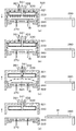
<第1の実施形態>
次に、熱処理装置40の第1の実施形態について説明する。図5は、第1の実施形態にかかる熱処理装置40の構成の概略を模式的に示す縦断面図である。図6は、第1の実施形態にかかる熱処理装置40の構成の概略を模式的に示す平面図である。
<First Embodiment>
Next, the first embodiment of the
熱処理装置40は、内部を閉鎖可能な処理容器300を有している。処理容器300のウェハ搬送領域D側の側面には、ウェハWの搬入出口(図示せず)が形成され、当該搬入出口には開閉シャッタ(図示せず)が設けられている。
The
処理容器300の内部には、ウェハWを加熱処理する加熱部310と、ウェハWを温度調節する温度調節部311が設けられている。加熱部310と温度調節部311はY方向に並べて配置されている。
Inside the
図7に示すように加熱部310は、ウェハWを収容して加熱処理する処理チャンバ320を有している。処理チャンバ320は、上側に位置して昇降自在な上部チャンバ321と、下側に位置して上部チャンバ321と一体となって内部を密閉可能な下部チャンバ322と、を有している。
As shown in FIG. 7, the
上部チャンバ321は、下面が開口した略円筒形状を有している。上部チャンバ321の内部であって、後述する熱処理板360に対向する位置には、処理チャンバ320の内部に水分含有ガスを供給する、水分供給部としてのシャワーヘッド330が設けられている。シャワーヘッド330は、上部チャンバ321と同期して昇降自在に構成されている。
The
シャワーヘッド330の下面には、複数のガス供給孔331が形成されている。複数のガス供給孔331は、シャワーヘッド330の下面において、後述する中央排気路340以外の部分に均一に配置されている。シャワーヘッド330には、ガス供給管332が接続されている。さらにガス供給管332には、シャワーヘッド330に水分含有ガスを供給するガス供給源333が接続されている。また、ガス供給管332には、水分含有ガスの流通を制御するバルブ334が設けられている。
A plurality of gas supply holes 331 are formed on the lower surface of the
ガス供給源333の内部には、水分濃度が例えば43%〜60%に調節されたガスが貯留されている。そして、このように水分濃度が調節された水分含有ガスがシャワーヘッド330を介して処理チャンバ320の内部に供給されることで、当該処理チャンバ320の内部雰囲気が所定の範囲、例えば43%〜60%の湿度に調節される。
Inside the
ここで、PEB処理において処理雰囲気中の水は、金属含有レジストの凝集反応を促進させる。凝集反応は、露光処理における紫外線によって金属含有レジスト中の金属とリガンド(有機金属錯体)との結合が切断され、リガンドが放出された状態で、PEB処理において金属の酸化物が生成される反応である。そして、PEB処理における水によって、この金属がより酸化され、凝集反応が促進される。例えば処理チャンバ320の内部雰囲気の湿度が大きくて水が多い場合、金属含有レジストの凝集反応が促進される。そうすると、金属含有レジストがネガ型のレジストであるため、ウェハW上に形成されるレジストパターンの寸法、例えば線幅が大きくなる。一方、処理チャンバ320の内部雰囲気の湿度が小さくて水が少ない場合、金属含有レジストの凝集反応はあまり進まず、レジストパターンの寸法は小さくなる。したがって、レジストパターンの寸法を適切に制御するためには、湿度を制御することが重要である。
Here, in the PEB treatment, water in the treatment atmosphere promotes the agglutination reaction of the metal-containing resist. The agglutination reaction is a reaction in which a metal oxide is produced in the PEB treatment in a state where the bond between the metal in the metal-containing resist and the ligand (organic metal complex) is broken by ultraviolet rays in the exposure treatment and the ligand is released. is there. Then, the water in the PEB treatment further oxidizes this metal and promotes the agglutination reaction. For example, when the humidity of the internal atmosphere of the
また、上述したように本発明者らが鋭意検討したところ、金属含有レジストは水分に対して感度が高いことが分かった。そして、PEB処理中の処理チャンバ320の内部雰囲気が43%〜60%の湿度に維持されていると、レジストパターンの寸法がウェハ面内で均一になることが知見された。具体的には、42%より小さい湿度の雰囲気下でPEB処理を行うと、レジストパターンの寸法が不均一になった。
Further, as described above, as a result of diligent studies by the present inventors, it was found that the metal-containing resist has high sensitivity to moisture. It was found that when the internal atmosphere of the
なお、本発明者らは、金属含有レジストが温度に対しては感度が低いことも知見している。 The present inventors have also found that metal-containing resists have low sensitivity to temperature.
図7に示すようにシャワーヘッド330には、当該シャワーヘッド330の下面中央部から上面中央部に延伸する中央排気路340が形成されている。中央排気路340には、上部チャンバ321の上面中央部に設けられた中央排気管341が接続されている。さらに中央排気管341には、例えば真空ポンプなどの排気装置342が接続されている。また、中央排気管341には、排気されたガスの流通を制御するバルブ343が設けられている。なお、本実施形態では、中央排気路340、中央排気管341、排気装置342及びバルブ343が、本発明における中央排気部を構成している。
As shown in FIG. 7, the
上部チャンバ321の内部であってシャワーヘッド330の外周部には、処理チャンバ320の外周部から当該処理チャンバ320の内部を排気する外周排気路350が形成されている。外周排気路350には、上部チャンバ321の上面に設けられた外周排気管351が接続されている。さらに外周排気管351には、例えば真空ポンプなどの排気装置352が接続されている。また、外周排気管351には、排気されたガスの流通を制御するバルブ353が設けられている。なお、本実施形態では、外周排気路350、外周排気管351、排気装置352及びバルブ353が、本発明における外周排気部を構成している。
An outer
下部チャンバ322は、上面が開口した略円筒形状を有している。下部チャンバ322の上面開口部には、熱処理板360と、当該熱処理板360を収容して熱処理板360の外周部を保持する環状の保持部材361と、が設けられている。熱処理板360は、厚みのある略円盤形状を有し、ウェハWを載置して加熱することができる。また、熱処理板360には、例えばヒータ362が内蔵されている。そして、熱処理板360の加熱温度は例えば制御部200により制御され、熱処理板360上に載置されたウェハWが所定の温度に加熱される。
The
下部チャンバ322の内部であって熱処理板360の下方には、ウェハWを下方から支持し昇降させる、昇降部としての昇降ピン370が例えば3本設けられている。昇降ピン370は、昇降駆動部371により上下動できる。熱処理板360の中央部付近には、当該熱処理板360を厚み方向に貫通する貫通孔372が例えば3箇所に形成されている。そして、昇降ピン370は貫通孔372を挿通し、熱処理板360の上面から突出可能になっている。
Inside the
図5及び図6に示すように温度調節部311は、温度調節板380を有している。温度調節板380は、略方形の平板形状を有し、熱処理板360側の端面が円弧状に湾曲している。温度調節板380には、Y方向に沿った2本のスリット381が形成されている。スリット381は、温度調節板380の熱処理板360側の端面から温度調節板380の中央部付近まで形成されている。このスリット381により、温度調節板380が、加熱部310の昇降ピン370及び後述する温度調節部311の昇降ピン390と干渉するのを防止できる。また、温度調節板380には、例えば冷却水やペルチェ素子などの温度調節部材(図示せず)が内蔵されている。温度調節板380の温度は例えば制御部200により制御され、温度調節板380上に載置されたウェハWが所定の温度に調節される。
As shown in FIGS. 5 and 6, the
温度調節板380は、支持アーム382に支持されている。支持アーム382には、駆動部383が取り付けられている。駆動部383は、Y方向に延伸するレール384に取り付けられている。レール384は、温度調節部311から加熱部310まで延伸している。この駆動部383により、温度調節板380は、レール384に沿って加熱部310と温度調節部311との間を移動可能になっている。
The
温度調節板380の下方には、ウェハWを下方から支持し昇降させるための昇降ピン390が例えば3本設けられている。昇降ピン390は、昇降駆動部391により上下動できる。そして、昇降ピン390はスリット381を挿通し、温度調節板380の上面から突出可能になっている。
Below the
次に、以上のように構成された熱処理装置40を用いて行われるPEB処理について説明する。図8は、熱処理装置40の動作を示す説明図である。なお、熱処理装置40に搬入されるウェハWには、金属含有レジスト膜が形成されている。
Next, the PEB treatment performed by using the
先ず、ウェハ搬送装置70によって熱処理装置40にウェハWが搬入されると、ウェハWはウェハ搬送装置70から予め上昇して待機していた昇降ピン390に受け渡される。続いて昇降ピン390を下降させ、ウェハWを温度調節板380に載置する。
First, when the wafer W is carried into the
その後、駆動部383により温度調節板380をレール384に沿って熱処理板360の上方まで移動させ、ウェハWは予め上昇して待機していた昇降ピン370に受け渡される。
After that, the
その後、図8(a)に示すように上部チャンバ321を下降させ、上部チャンバ321と下部チャンバ322を当接させて、処理チャンバ320の内部が密閉される。その後、昇降ピン370を下降させて、ウェハWを熱処理板360に載置する。そして、熱処理板360上のウェハWを、所定の温度に加熱する(工程A1)。
After that, as shown in FIG. 8A, the
この工程A1では、シャワーヘッド330から水分濃度が例えば43%〜60%に調節された水分含有ガスが例えば4L/minの流量で供給され、処理チャンバ320の内部雰囲気が例えば43%〜60%の湿度に調節される。そして、この水分含有ガスに含まれる水分が、ウェハWの金属含有レジスト膜に結露付着し、この水分により、金属含有レジストの凝集反応が促進される。凝集反応では、水分により金属が酸化されて、金属含有レジストが凝縮する。そして、このように金属含有レジストの凝集反応を進めることで、レジストパターンの寸法が決定される。
In this step A1, a water-containing gas having a water concentration adjusted to, for example, 43% to 60% is supplied from the
また、工程A1では、シャワーヘッド330の複数のガス供給孔331から水分含有ガスがウェハWに対して均一に供給されるので、金属含有レジストの凝集反応をウェハ面内で均一に行うことができ、レジストパターンの寸法をウェハ面内で均一にすることができる。
Further, in step A1, since the water-containing gas is uniformly supplied to the wafer W from the plurality of gas supply holes 331 of the
さらに、工程A1では、外周排気路350(処理チャンバ320の外周部)から当該処理チャンバ320の内部を、第1の排気量、例えば4L/min以上で排気する。このように処理チャンバ320の内部を外周部から低排気することで、金属含有レジストの凝集反応をウェハ面内でさらに均一に行うことができる。
Further, in step A1, the inside of the
なお、工程A1の加熱処理では、金属含有レジストの凝集反応が進む分、当該金属含有レジストからの金属含有昇華物が発生する。 In the heat treatment of step A1, a metal-containing sublimated product is generated from the metal-containing resist as the agglutination reaction of the metal-containing resist proceeds.
その後、図8(b)に示すようにシャワーヘッド330からの水分含有ガスの供給を停止し、金属含有レジストの凝集反応を停止させる(工程A2)。この工程A2の段階では、金属含有レジストの凝集反応が停止しているので、レジストパターンに対する影響が小さく、また金融含有レジストからの金属含有昇華物の発生も抑制される。
After that, as shown in FIG. 8B, the supply of the water-containing gas from the
なお、工程A2では、外周排気路350からの処理チャンバ320の内部の排気は、上述した第1の排気量で継続して行う。
In step A2, the internal exhaust of the
その後、図8(c)に示すように上部チャンバ321を上昇させ、処理チャンバ320の外周部から内部に外気を流入させると共に、中央排気路340(処理チャンバ320の中央部)から当該処理チャンバ320の内部を、第1の排気量よりも大きい第2の排気量、例えば20L/min〜70L/minで排気する(工程A3)。このように処理チャンバ320の内部を中央部から高排気することで、処理チャンバ320の内部の金属含有昇華物を回収し、当該金属含有昇華物の濃度を低下させることができる。したがって、金属汚染を抑制することができ、半導体デバイスの欠陥を抑制することができる。
After that, as shown in FIG. 8C, the
また、工程A3では、処理チャンバ320の中央部から排気し、しかも処理チャンバ320の外周部から外気を流入させているので、金属含有昇華物が処理チャンバ320の外部に漏れることがない。したがって、金属汚染をさらに抑制することができる。
Further, in the step A3, since the exhaust is exhausted from the central portion of the
なお、工程A3では、処理チャンバ320の中央部からの排気に加えて、外周部からも排気してもよい。但し、排気する経路が少ない方が高速で排気することができるので、中央部からのみ排気するのが好ましい。
In step A3, in addition to the exhaust from the central portion of the
その後、図8(d)に示すように上部チャンバ321をさらに上昇させる。そして、昇降ピン370によってウェハWを上昇させると共に、温度調節板380を熱処理板360の上方に移動させ、続いてウェハWは昇降ピン370から温度調節板380に受け渡される。その後、温度調節板380をウェハ搬送領域D側に移動させ、この温度調節板380の移動中に、ウェハWは所定の温度に調節される(工程A4)。
After that, the
本実施形態によれば、工程A1において処理チャンバ320の内部に水分含有ガスが供給されるので、金属含有レジストの凝集反応を促進でき、レジストパターンの寸法を均一にすることができる。また、工程A3において処理チャンバ320の内部を高排気しているので、工程A1で発生した金属含有昇華物を回収することができ、金属汚染を抑制することができる。その結果、半導体デバイスの欠陥を抑制することができる。また、金属汚染を抑制することで、処理チャンバ320のクリーニングやメンテナンス頻度を抑制するという効果も生じる。
According to the present embodiment, since the water-containing gas is supplied to the inside of the
以上の実施形態では、工程A1において金属含有レジストの凝集反応を促進させた後、工程A2において水分含有ガスの供給を停止して、金属含有レジストの凝集反応を停止させる場合について説明した。かかる場合、工程A2では、金属含有昇華物の発生が減衰する。 In the above embodiment, the case where the agglutination reaction of the metal-containing resist is promoted in the step A1 and then the supply of the water-containing gas is stopped in the step A2 to stop the agglutination reaction of the metal-containing resist has been described. In such a case, in step A2, the generation of the metal-containing sublimated product is attenuated.
一方、例えば工程A1の終了後に、金属含有レジスト中のリガンドが完全に放出されずその一部が残り、工程A2において水分含有ガスの供給を停止しても、金属含有レジストの凝集反応が停止しない場合がある。かかる場合、工程A2でも金属含有昇華物が継続的に発生し減衰しない。 On the other hand, for example, after the end of step A1, the ligand in the metal-containing resist is not completely released and a part thereof remains, and even if the supply of the water-containing gas is stopped in step A2, the aggregation reaction of the metal-containing resist does not stop. In some cases. In such a case, the metal-containing sublimated product is continuously generated even in step A2 and is not attenuated.
以下においては、第1の実施形態の変形例として、このように水分含有ガスの供給を停止しても、金属含有昇華物が継続的に発生する場合について説明する。図9は、熱処理装置40の動作を示す説明図である。
In the following, as a modified example of the first embodiment, a case where the metal-containing sublimated product is continuously generated even if the supply of the water-containing gas is stopped in this way will be described. FIG. 9 is an explanatory diagram showing the operation of the
先ず、図9(a)に示すように処理チャンバ320の内部を密閉した状態で、ウェハWを熱処理板360に載置し、所定の温度に加熱する(工程B1)。この工程B1は、上記工程A1と同様である。すなわち、工程B1では、シャワーヘッド330から水分濃度が例えば43%〜60%に調節された水分含有ガスが例えば4L/minの流量で供給され、処理チャンバ320の内部雰囲気が例えば43%〜60%の湿度に調節される。そして、金属含有レジストの凝集反応が促進される。また、外周排気路350(処理チャンバ320の外周部)から当該処理チャンバ320の内部を、第1の排気量、例えば4L/min以上で排気する。
First, as shown in FIG. 9A, the wafer W is placed on the
その後、図9(b)に示すようにシャワーヘッド330からの水分含有ガスの供給を停止すると共に、外周排気路350からの処理チャンバ320の内部の排気を停止する。そして、上部チャンバ321を上昇させ、処理チャンバ320の外周部から内部に外気を流入させると共に、中央排気路340(処理チャンバ320の中央部)から当該処理チャンバ320の内部を、第2の排気量、例えば20L/min〜70L/minで排気する(工程B2)。
After that, as shown in FIG. 9B, the supply of the water-containing gas from the
工程B2では、水分含有ガスの供給を停止しているが、ウェハWが熱処理板360に載置されており、金属含有昇華物が継続的に発生している。そこで、処理チャンバ320の内部を中央部から高排気することで、このように継続的に発生する金属含有昇華物を回収し、処理チャンバ320の内部における金属含有昇華物の濃度を低下させる。
In step B2, the supply of the water-containing gas is stopped, but the wafer W is placed on the
その後、工程B2における金属含有昇華物の回収がある程度終了したところで、図9(c)に示すように昇降ピン370によってウェハWを上昇させ、ウェハWを熱処理板360から離間させると共に、中央排気路340からの排気を継続して行う(工程B3)。すなわち、処理チャンバ320の中央部から当該処理チャンバ320の内部を、第2の排気量、例えば20L/min〜70L/minで排気する。
After that, when the recovery of the metal-containing sublimated material in step B2 is completed to some extent, the wafer W is raised by the elevating
工程B3では、ウェハWを熱処理板360から離間させているので、ウェハWの熱処理が停止し、金属含有レジストの凝集反応も停止する。そして、金融含有レジストからの金属含有昇華物の発生も抑制される。
In step B3, since the wafer W is separated from the
また、工程B3では、処理チャンバ320の内部を中央部から高排気することで、処理チャンバ320の内部の金属含有昇華物を回収し、当該金属含有昇華物の濃度を低下させることができる。したがって、金属汚染を抑制することができる。また、工程B3では、処理チャンバ320の中央部から排気し、しかも処理チャンバ320の外周部から外気を流入させているので、金属含有昇華物が処理チャンバ320の外部に漏れることがない。したがって、金属汚染をさらに抑制することができる。
Further, in step B3, by highly exhausting the inside of the
その後、図9(d)に示すように上部チャンバ321をさらに上昇させる。そして、ウェハWは昇降ピン370から温度調節板380に受け渡され、その後、温度調節板380の移動中に、ウェハWは所定の温度に調節される(工程B4)。この工程B4は、上記工程A4と同様である。
After that, the
本実施形態でも、上記実施形態と同様の効果を享受することができる。すなわち、工程B1において処理チャンバ320の内部に水分含有ガスを供給することで、金属含有レジストの凝集反応を促進でき、レジストパターンの寸法を均一にすることができる。また、工程B2及び工程B3において処理チャンバ320の内部を中央部から高排気することで、金属含有昇華物を回収することができ、金属汚染を抑制することができる。
In this embodiment as well, the same effects as those in the above embodiment can be enjoyed. That is, by supplying the water-containing gas to the inside of the
なお、第1の実施形態では、金属含有材料として金属含有レジストを用いた場合について説明したが、第1の実施形態は他の金属含有材料にも適用できる。例えば金属含有材料として、メタルハードマスク材料を用いてもよい。メタルハードマスク材料に含まれる金属は任意であるが、例えばチタン、ジルコニウムなどである。 Although the case where the metal-containing resist is used as the metal-containing material has been described in the first embodiment, the first embodiment can be applied to other metal-containing materials. For example, a metal hard mask material may be used as the metal-containing material. The metal contained in the metal hard mask material is arbitrary, such as titanium and zirconium.
レジストパターンの微細化を実現するため、近年、ウェハW上にメタルハードマスクを形成することが提案されている。このメタルハードマスクを形成するあたり、現状の課題は、ウェハW上にメタルハードマスク材料をスピン塗布した後、メタルハードマスクの熱処理もしくはメタルハードマスクをウェットエッチング後の熱処理をする際に、ウェハ面内で膜厚が均一にならない場合があることである。 In recent years, it has been proposed to form a metal hard mask on a wafer W in order to realize miniaturization of a resist pattern. In forming this metal hard mask, the current problem is when the metal hard mask material is spin-coated on the wafer W and then the metal hard mask is heat-treated or the metal hard mask is wet-etched and then heat-treated. The film thickness may not be uniform within.
本発明者らが鋭意検討したところ、このウェットエッチングの不均一性の要因は、メタルハードマスクの膜質斑であり、さらにこの膜質斑は、スピン塗布されたメタルハードマスクを熱処理する際の雰囲気が要因で生じることが分かった。例えばウェハWの外周部一端から排気する場合、ウェハ面内にその一端に向かう気流が生じる。また、ウェハWの中心部から排気する場合、ウェハ面内に外周部から中心部に向かう気流が生じる。このような気流が、メタルハードマスクの膜質斑を生じさせる。 As a result of diligent studies by the present inventors, the cause of the non-uniformity of the wet etching is the film quality spots of the metal hard mask, and further, the film quality spots have an atmosphere when the spin-coated metal hard mask is heat-treated. It turned out that it was caused by a factor. For example, when exhausting from one end of the outer peripheral portion of the wafer W, an air flow toward the one end is generated in the wafer surface. Further, when exhausting from the central portion of the wafer W, an air flow from the outer peripheral portion to the central portion is generated in the wafer surface. Such airflow causes membranous spots on the metal hardmask.
また、メタルハードマスクを熱処理すると、金属含有レジストと同様に、金属含有昇華物が発生する。したがって、この金属含有昇華物を回収し、金属汚染を抑制する必要もある。 Further, when the metal hard mask is heat-treated, a metal-containing sublimated product is generated as in the case of the metal-containing resist. Therefore, it is also necessary to recover this metal-containing sublimated product and suppress metal contamination.
この点、第1の実施形態において、金属含有材料としてメタルハードマスク材料を用いた場合、工程A1及び工程B1において、シャワーヘッド330から水分含有ガスを均一に供給され、外周排気路350から処理チャンバ320の内部を均一に排気するので、ウェハWの気流を均一にすることができる。したがって、メタルハードマスクの膜質斑を抑制して膜質を均一化し、当該メタルハードマスクのウェットエッチングを均一に行うことができる。
In this respect, when the metal hard mask material is used as the metal-containing material in the first embodiment, the water-containing gas is uniformly supplied from the
また、工程A1及び工程B1において、水分含有ガスに含まれる水分によって、メタルハードマスクの凝集反応を促進することができる。 Further, in the steps A1 and B1, the agglutination reaction of the metal hard mask can be promoted by the moisture contained in the moisture-containing gas.
また、工程A3、工程B2及びB3において、中央排気路340から処理チャンバ320の内部を高排気するので、処理チャンバ320の内部の金属含有昇華物を回収し、当該金属含有昇華物の濃度を低下させることができる。したがって、金属汚染を抑制することができる。その結果、処理中のウェハWの欠陥を抑制することができ、さらに後続のウェハWに金属が付着して欠陥が生じるのを抑制することができる。また、ウェハWを入れ替えるため、上部チャンバ321を上昇させた際、金属含有昇華物が外部に漏れるのも抑制することができる。
Further, in steps A3, B2 and B3, since the inside of the
<第2の実施形態>
次に、熱処理装置40の第2の実施形態について説明する。第2の実施形態における熱処理装置40は、第1の実施形態における熱処理装置40と加熱部310の構成が変更されており、その他は同様の構成を有している。
<Second embodiment>
Next, a second embodiment of the
先ず、加熱部310の構成について説明する。図10は、第2の実施形態にかかる加熱部310の構成の概略を模式的に示す縦断面図である。
First, the configuration of the
加熱部310の上部チャンバ321の内部には、第1の実施形態におけるシャワーヘッド330に代えて、処理チャンバ320の内部に水分含有ガスを供給する、水分供給部としてのガス供給リング400が設けられている。ガス供給リング400は、上部チャンバ321の外周部に沿って環状に設けられている。
Inside the
図11に示すようにガス供給リング400の上面には、当該ガス供給リング400の周上に等間隔で複数のガス供給孔401が形成されている。ガス供給リング400は、この複数のガス供給孔401により、上方に向けて水分含有ガスを均一に供給することができる。
As shown in FIG. 11, on the upper surface of the
図10に示すようにガス供給リング400には、ガス供給管402が接続されている。さらにガス供給管402には、ガス供給リング400に水分含有ガスを供給するガス供給源403が接続されている。また、ガス供給管402には、水分含有ガスの流通を制御するバルブ404が設けられている。
As shown in FIG. 10, a
ガス供給源403の内部には、第1の実施形態におけるガス供給源333と同様に、水分濃度が例えば43%〜60%に調節されたガスが貯留されている。そして、このように水分濃度が調節された水分含有ガスがガス供給リング400を介して処理チャンバ320の内部に供給されることで、当該処理チャンバ320の内部雰囲気が所定の範囲、例えば43%〜60%の湿度に調節される。
Similar to the
上部チャンバ321の外周部であって、ガス供給リング400の内側には、環状のガス流通部としての内側シャッタ410が設けられている。すなわち、上部チャンバ321、ガス供給リング400及び内側シャッタ410で囲まれるガス流通路411が、上部チャンバ321の外周部に沿って環状に形成されている。また、ガス流通路411に外気が流入するのを防止するため、上部チャンバ321、ガス供給リング400、内側シャッタ410のそれぞれの間は密閉されている。
An
図12に示すように内側シャッタ410には、当該内側シャッタ410は周上に等間隔で複数のガス流通孔412が形成されている。内側シャッタ410は、このガス流通孔412により、処理チャンバ320の内部に向けて水平方向に均一に水分含有ガスを供給することができる。
As shown in FIG. 12, the
上部チャンバ321の上面中央部には、中央排気管420が接続されている。さらに中央排気管420には、例えば真空ポンプなどの排気装置421が接続されている。また、中央排気管420には、排気されたガスの流通を制御するバルブ422が設けられている。なお、本実施形態では、中央排気管420、排気装置421及びバルブ422が、本発明における中央排気部を構成している。
A
なお、加熱部310のその他の構成は、第1の実施形態における加熱部310の構成と同様であるので説明を省略する。
Since the other configurations of the
以上のように構成された加熱部310では、処理チャンバ320の内部を密閉した状態で、ウェハWを熱処理板360に載置し、所定の温度に加熱する(PEB処理)。
In the
PEB処理では、ガス供給リング400から内側シャッタ410を介して処理チャンバ320の内部に向けて、水分濃度が例えば43%〜60%に調節された水分含有ガスが例えば20L/min〜70L/minの流量で供給され、処理チャンバ320の内部雰囲気が例えば43%〜60%の湿度に調節される。このように処理チャンバ320の内部雰囲気を所定の湿度に調節することで、金属含有レジストの凝集反応を促進して、レジストパターンの寸法を均一にすることができる。
In the PEB treatment, the water-containing gas whose water concentration is adjusted to, for example, 43% to 60% is, for example, 20 L / min to 70 L / min toward the inside of the
また、PEB処理では、処理チャンバ320の内部を中央排気管420(処理チャンバ320の中央部)から当該処理チャンバ320の内部を、例えば20L/min〜70L/minで排気する。このように処理チャンバ320の内部を中央部から高排気することで、処理チャンバ320の内部の金属含有昇華物を回収し、当該金属含有昇華物の濃度を低下させることができる。したがって、金属汚染を抑制することができる。
Further, in the PEB treatment, the inside of the
なお、PEB処理において、ガス供給リング400から供給される水分含有ガスの流量と、中央排気管420から排気される排気量はほぼ同量である。
In the PEB treatment, the flow rate of the water-containing gas supplied from the
また、第2の実施形態では、金属含有材料として金属含有レジストを用いた場合について説明したが、第2の実施形態は第1の実施形態と同様に、他の金属含有材料、例えばメタルハードマスク材料にも適用できる。 Further, in the second embodiment, the case where a metal-containing resist is used as the metal-containing material has been described, but in the second embodiment, as in the first embodiment, another metal-containing material, for example, a metal hard mask It can also be applied to materials.
<第3の実施形態>
以上の第1の実施形態及び第2の実施形態では、PEB処理中の処理チャンバ320の内部に水分含有ガスを供給していたが、PEB処理前に、金属含有レジスト膜に水分を供給してもよい。また、このPEB処理前の水分供給は、熱処理装置40の内部で行ってもよいし、熱処理装置40の外部で行ってもよい。
<Third embodiment>
In the above first embodiment and the second embodiment, the water-containing gas was supplied to the inside of the
先ず、PEB処理前の水分供給が、熱処理装置40の内部で行われる場合について説明する。図13は、第3の実施形態にかかる熱処理装置40の構成の概略を模式的に示す縦断面図である。
First, a case where the water supply before the PEB treatment is performed inside the
熱処理装置40は、第1の実施形態の熱処理装置40と同様の構成を有し、さらに処理容器300の内部には、ウェハW上の金属含有レジスト膜に水分含有ガスを供給する、水分供給部としての水供給ノズル500が設けられている。なお、水分含有ガスには、液体の水(ミスト)が含まれていてもよい。また、水供給ノズル500は、液体の水を吐出してもよい。
The
水供給ノズル500は、温度調節部311の温度調節板380の上方に設けられ、移動機構501によって水平方向に移動自在に構成されている。また、水供給ノズル500はウェハWの径と同じかそれよりも長い細長形状を有し、水供給ノズル500の吐出口はスリット状に形成されている。そして、水供給ノズル500は、ウェハWの上方を水平方向に移動しながら水分含有ガスを吐出することで、ウェハW上の金属含有レジスト膜の全面に水分含有ガスを供給する。供給された水分含有ガスは金属含有レジスト膜に結露付着し、当該金属含有レジスト膜の全面に水が供給される。
The
水供給ノズル500には、水供給管502が接続されている。さらに水供給管502には、水供給ノズル500に水分含有ガスを供給する水供給源503が接続されている。また、水供給管502には、水分含有ガスの流通を制御するバルブ504が設けられている。
A
なお、加熱部310の上部チャンバ321において、第1の実施形態におけるシャワーヘッド330、ガス供給管332、ガス供給源333、バルブ334、外周排気路350、外周排気管351、排気装置352、バルブ353が省略されている。すなわち、上部チャンバ321には、中央排気管341、排気装置342、バルブ343が設けられている。
In the
次に、以上のように構成された熱処理装置40を用いて行われるPEB処理について説明する。
Next, the PEB treatment performed by using the
先ず、ウェハ搬送装置70によって熱処理装置40にウェハWが搬入されると、ウェハWはウェハ搬送装置70から予め上昇して待機していた昇降ピン390に受け渡される。続いて昇降ピン390を下降させ、ウェハWを温度調節板380に載置する。
First, when the wafer W is carried into the
その後、移動機構501によって水供給ノズル500をウェハの上方を水平方向に移動させながら、当該水供給ノズル500から水分含有ガスを吐出する。吐出された水分含有ガスは金属含有レジスト膜に結露付着し、当該金属含有レジスト膜の全面に水が供給される。なお、このときの水の供給量は、上述した第1の実施形態における処理チャンバ320の内部雰囲気の所定の湿度、例えば43%〜60%に相当する量である。
After that, the
その後、駆動部383により温度調節板380をレール384に沿って熱処理板360の上方まで移動させ、ウェハWは予め上昇して待機していた昇降ピン370に受け渡される。
After that, the
その後、上部チャンバ321を下降させ、上部チャンバ321と下部チャンバ322を当接させて、処理チャンバ320の内部が密閉される。その後、昇降ピン370を下降させて、ウェハWを熱処理板360に載置する。そして、熱処理板360上のウェハWを、所定の温度に加熱する。
After that, the
このウェハWの加熱処理においては、予め金属含有レジスト膜上に水が供給されているので、金属含有レジストの凝集反応を促進して、レジストパターンの寸法を均一にすることができる。 In the heat treatment of the wafer W, water is supplied onto the metal-containing resist film in advance, so that the agglutination reaction of the metal-containing resist can be promoted and the size of the resist pattern can be made uniform.
また、このウェハWの加熱処理においては、中央排気管341(処理チャンバ320の中央部)から当該処理チャンバ320の内部を、例えば20L/min〜70L/minで排気する。このように処理チャンバ320の内部を中央部から高排気することで、処理チャンバ320の内部の金属含有昇華物を回収し、当該金属含有昇華物の濃度を低下させることができる。したがって、金属汚染を抑制することができる。
Further, in the heat treatment of the wafer W, the inside of the
その後、上部チャンバ321を上昇させる。そして、昇降ピン370によってウェハWを上昇させると共に、温度調節板380を熱処理板360の上方に移動させ、続いてウェハWは昇降ピン370から温度調節板380に受け渡される。その後、温度調節板380をウェハ搬送領域D側に移動させ、この温度調節板380の移動中に、ウェハWは所定の温度に調節される。
After that, the
なお、PEB処理前の水分供給が熱処理装置40の内部で行われる場合において、水分供給部は水供給ノズル500に限定されない。例えば処理容器300に形成されたウェハWの搬入出口に水供給ノズル500を設けてもよく、かかる場合、処理容器300に搬入されるウェハWに対して、水供給ノズル500から水分含有ガスが供給される。
When the water supply before the PEB treatment is performed inside the
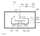
次に、PEB処理前の水分供給が、熱処理装置40の外部で行われる場合について説明する。図14は、第3の実施形態にかかる水塗布装置510の構成の概略を模式的に示す縦断面図である。
Next, a case where the water supply before the PEB treatment is performed outside the
水塗布装置510は、内部を閉鎖可能な処理容器520を有している。処理容器520のウェハ搬送領域D側の側面には、ウェハWの搬入出口(図示せず)が形成され、当該搬入出口には開閉シャッタ(図示せず)が設けられている。
The
処理容器520内の中央部には、ウェハWを保持して回転させるスピンチャック530が設けられている。スピンチャック530は、水平な上面を有し、当該上面には、例えばウェハWを吸引する吸引口(図示せず)が設けられている。この吸引口からの吸引により、ウェハWをスピンチャック530上に吸着保持できる。
A
スピンチャック530の下方には、例えばモータなどを備えた駆動部531が設けられている。スピンチャック530は、駆動部531により所定の速度に回転できる。また、駆動部531には、例えばシリンダなどの昇降駆動源が設けられており、スピンチャック530は昇降自在になっている。
Below the
スピンチャック530の周囲には、ウェハWから飛散又は落下する液体を受け止め、回収するカップ532が設けられている。カップ532の下面には、回収した液体を排出する排出管533と、カップ532内の雰囲気を真空引きして排気する排気管534が接続されている。
Around the
スピンチャック530の上方には、ウェハW上の金属含有レジスト膜に液体の水を供給する、水分供給部としての水供給ノズル540が設けられている。水供給ノズル540は、移動機構541によって水平方向に移動自在に構成されている。これにより、水供給ノズル540は、カップ532の外方に設置された待機部542からカップ532内のウェハWの中心部上方まで移動でき、さらに当該ウェハW上をウェハWの径方向に移動できる。
Above the
水供給ノズル540には、水供給管543が接続されている。さらに水供給管543には、水供給ノズル540に水を供給する水供給源544が接続されている。また、水供給管543には、水の流通を制御するバルブ545が設けられている。
A
そして、水塗布装置510では、スピンチャック530でウェハWを保持した後、移動機構541によって水供給ノズル540を当該ウェハWの中心部の上方まで移動させる。その後、スピンチャック530によってウェハWを回転させながら、水供給ノズル540からウェハWに水を供給する。供給された水は遠心力によりウェハWの全面に拡散されて、当該ウェハW上の金属含有レジスト膜の全面に水が塗布される。なお、このときの水の供給量は、上述した第1の実施形態における処理チャンバ320の内部雰囲気の所定の湿度、例えば43%〜60%に相当する量である。
Then, in the
以上の構成の水塗布装置510は、例えば基板処理システム1の第1のブロックG1に配置される。
The
そして、水塗布装置510における金属含有レジスト膜への水の供給は、図4に示した工程S2のPAB処理後であって、工程S5のPEB処理前のいずれかの工程で行われる。但し、ウェハ処理のスループットの観点からは、工程S4の露光処理前に行うのが好ましい。
Then, the water supply to the metal-containing resist film in the
なお、本実施形態の熱処理装置40は、図13に示した熱処理装置40から水分供給部を省略した構成、すなわち水供給ノズル500、移動機構501、水供給管502、水供給源503、バルブ504を省略した構成を有している。
The
本実施形態でも、上記実施形態と同様の効果を享受することができる。すなわち、熱処理装置40の水供給ノズル500からの水分含有ガスの供給に代えて、水塗布装置510の水供給ノズル540から金属含有レジスト膜に水を供給する。このため、熱処理装置40のPEB処理において、金属含有レジストの凝集反応を促進して、レジストパターンの寸法を均一にすることができる。また、PEB処理において処理チャンバ320の内部を中央部から高排気することで、金属含有昇華物を回収することができ、金属汚染を抑制することができる。
In this embodiment as well, the same effects as those in the above embodiment can be enjoyed. That is, instead of supplying the water-containing gas from the
なお、PEB処理前の水分供給が熱処理装置40の外部で行われる場合において、水分供給部は水塗布装置510における水供給ノズル540に限定されない。例えばインターフェイスステーション13に水分供給部を設け、当該水分供給部から水分含有ガスを供給し、インターフェイスステーション13の内部を高湿度化してもよい。
When the water supply before the PEB treatment is performed outside the
なお、第3の実施形態では、金属含有材料として金属含有レジストを用いた場合について説明したが、第3の実施形態は第1の実施形態及び第2の実施形態と同様に、他の金属含有材料、例えばメタルハードマスク材料にも適用できる。 In the third embodiment, the case where a metal-containing resist is used as the metal-containing material has been described, but the third embodiment contains other metals as in the first embodiment and the second embodiment. It can also be applied to materials such as metal hard mask materials.
<第4の実施形態>
次に、熱処理装置40の第4の実施形態について説明する。第4の実施形態における熱処理装置40は、第1の実施形態における熱処理装置40と加熱部310の構成が変更されており、その他は同様の構成を有している。
<Fourth Embodiment>
Next, a fourth embodiment of the
先ず、加熱部310の構成について説明する。図15は、第4の実施形態にかかる加熱部310の構成の概略を模式的に示す縦断面図である。
First, the configuration of the
加熱部310の上部チャンバ600は、第1の実施形態における上部チャンバ321に代えて設けられる。上部チャンバ600は、全体として下面が開口した略円筒形状を有している。上部チャンバ600は、天板601と、当該天板601の外周部から下方に設けられた開閉シャッタ602と、を有している。天板601は固定され、開閉シャッタ602が昇降自在に構成されている。
The
そして、開閉シャッタ602と下部チャンバ322が当接して、処理チャンバ320の内部が密閉される。すなわち、第1の実施形態では、上部チャンバ321自体を昇降させることで処理チャンバ320を開閉していたが、第4の実施形態では、開閉シャッタ602を開閉させることで処理チャンバ320を開閉している。
Then, the opening /
なお、加熱部310のその他の構成は、第1の実施形態における加熱部310の構成と同様であるので説明を省略する。
Since the other configurations of the
次に、以上のように構成された熱処理装置40を用いて行われるPEB処理について説明する。図16は、熱処理装置40の動作を示す説明図である。
Next, the PEB treatment performed by using the
先ず、図16(a)に示すよう開閉シャッタ602を上昇させ、処理チャンバ320の内部を密閉した状態で、ウェハWを熱処理板360に載置し、所定の温度に加熱する。この工程は、第1の実施形態における工程B1とほぼ同様である。すなわち、シャワーヘッド330から水分濃度が例えば43%〜60%に調節された水分含有ガスが例えば4L/minの流量で供給され、処理チャンバ320の内部雰囲気が例えば43%〜60%の湿度に調節される。そして、金属含有レジストの凝集反応が促進される。また、外周排気路350(処理チャンバ320の外周部)から当該処理チャンバ320の内部を、例えば4L/min以上で排気する。
First, as shown in FIG. 16A, the open /
その後、図16(b)に示すように昇降ピン370によってウェハWを上昇させ、ウェハWを熱処理板360から離間させる。この状態で、シャワーヘッド330からの水分含有ガスの供給を停止すると共に、外周排気路350からの処理チャンバ320の内部の排気を停止する。そして、中央排気路340(処理チャンバ320の中央部)から当該処理チャンバ320の内部を、例えば20L/min〜70L/minで排気する。この際、ウェハWを熱処理板360から離間させているので、金属含有レジストの凝集反応を停止させ、金融含有レジストからの金属含有昇華物の発生が抑制される。また、ウェハWを中央排気路340に近づけているので、金属含有昇華物をより効率よく回収することができる。なお、この工程は、第1の実施形態における工程B3とほぼ同様であり、例えば10秒〜15秒間行われる。
After that, as shown in FIG. 16B, the wafer W is raised by the elevating
その後、図16(c)に示すように開閉シャッタ602を下降させ、処理チャンバ320を開放する。この際、図16(b)に示したように金属含有昇華物の発生が抑制され、当該金属含有昇華物が適切に回収されているので、金属含有昇華物が外部に漏れるのを抑制することができる。
After that, as shown in FIG. 16C, the opening /
そして、図16(d)に示すようにウェハWは昇降ピン370から温度調節板380に受け渡され、その後、温度調節板380の移動中に、ウェハWは所定の温度に調節される。この工程は、第1の実施形態における工程B4とほぼ同様である。
Then, as shown in FIG. 16D, the wafer W is handed over from the elevating
本実施形態でも、上記実施形態と同様の効果を享受することができる。すなわち、処理チャンバ320の内部に水分含有ガスを供給することで、金属含有レジストの凝集反応を促進でき、レジストパターンの寸法を均一にすることができる。また、処理チャンバ320の内部を中央部から高排気することで、金属含有昇華物を回収することができ、金属汚染を抑制することができる。
In this embodiment as well, the same effects as those in the above embodiment can be enjoyed. That is, by supplying the water-containing gas to the inside of the
なお、第4の実施形態では、金属含有材料として金属含有レジストを用いた場合について説明したが、第4の実施形態は第1の実施形態〜第3の実施形態と同様に、他の金属含有材料、例えばメタルハードマスク材料にも適用できる。 In the fourth embodiment, the case where a metal-containing resist is used as the metal-containing material has been described, but the fourth embodiment contains other metals as in the first to third embodiments. It can also be applied to materials such as metal hard mask materials.
<第5の実施形態>
以上の第1の実施形態〜第4の実施形態では、PEB処理前又はPEB処理中に金属含有膜としての金属含有レジスト膜に水分を供給していたが、例えば金属含有膜がメタルハードマスクの場合、金属含有レジストに比べて水分に対する感度が小さいため、積極的な水分供給を省略してもよい。
<Fifth Embodiment>
In the above first to fourth embodiments, water is supplied to the metal-containing resist film as the metal-containing film before or during the PEB treatment. For example, the metal-containing film is a metal hard mask. In this case, since the sensitivity to water is smaller than that of the metal-containing resist, the active water supply may be omitted.
但し、かかる場合であっても、上述したようにウェットエッチングの不均一性の要因となるメタルハードマスクの膜質斑を抑制するため、熱処理における気流を制御する必要がある。そこで、熱処理装置40の加熱部310において、処理チャンバ320の内部の気流を乱す要因となる外気を流入させないようにするため、処理チャンバ320(上部チャンバ321)の外周部に、鉛直方向且つ環状に気流(いわゆるエアカーテン)を形成してもよい。
However, even in such a case, it is necessary to control the air flow in the heat treatment in order to suppress the film quality unevenness of the metal hard mask which causes the non-uniformity of wet etching as described above. Therefore, in the
熱処理装置40の第5の実施形態は、加熱部310においてかかるエアカーテンを形成するものである。第5の実施形態における熱処理装置40は、第1の実施形態における熱処理装置40と加熱部310の構成が変更されており、その他は同様の構成を有している。
A fifth embodiment of the
先ず、加熱部310の構成について説明する。図17は、第5の実施形態にかかる加熱部310の構成の概略を模式的に示す縦断面図である。
First, the configuration of the
加熱部310の上部チャンバ321には、第1の実施形態におけるシャワーヘッド330、ガス供給管332、ガス供給源333、バルブ334、中央排気管341、排気装置342、バルブ343、外周排気路350、外周排気管351、排気装置352、バルブ353が省略されている。
In the
上部チャンバ321の上面外周部には、処理チャンバ320の外周部にエアを供給する、エア供給部としてのエア供給リング700が設けられている。エア供給リング700は、上部チャンバ321の外周部に沿って環状に設けられている。また、エア供給リング700のエア供給孔も、エア供給リング700に沿って環状に形成されている。
An
エア供給リング700には、エア供給管701が接続されている。さらにエア供給管701には、エア供給リング700にエアを供給するエア供給源702が接続されている。また、エア供給管701には、エアの流通を制御するバルブ703が設けられている。
An
上部チャンバ321の側面下端部には、エア供給リング700から供給されたエアを排出する、エア排出部としての排気リング710が設けられている。排気リング710は、上部チャンバ321の外周部に沿って環状に設けられている。
An
排気リング710には、排気管711が接続されている。さらに排気管711には、例えば真空ポンプなどの排気装置712が接続されている。また、排気管711には、排気されたエアの流通を制御するバルブ713が設けられている。
An
なお、加熱部310のその他の構成は、第1の実施形態における加熱部310の構成と同様であるので説明を省略する。
Since the other configurations of the
以上のように構成された加熱部310では、処理チャンバ320の内部を密閉した状態で、ウェハWを熱処理板360に載置し、所定の温度に加熱する。熱処理では、エア供給リング700から供給されたエアは排気リング710から排出され、いわゆるエアカーテンが形成される。このエアカーテンにより、処理チャンバ320の内部への外気の流入が抑制されるので、熱処理中の気流の発生を抑制することができる。したがって、メタルハードマスクの膜質斑を抑制し、当該メタルハードマスクのウェットエッチングを均一に行うことができる。
In the
なお、以上の実施形態では、エアカーテンは、上方から下方に向かう気流によって形成されていたが、逆に下方から上方に向かう気流によって形成してもよい。 In the above embodiment, the air curtain is formed by the air flow from the upper side to the lower side, but conversely, the air curtain may be formed by the air flow from the lower side to the upper side.
また、第5の実施形態における処理チャンバ320の外周部のエアカーテンは、上記第1の実施形態〜第4の実施形態に適用してもよい。例えば第1の実施形態の工程A1の熱処理において、処理チャンバ320の外周部にエアカーテンを形成し、処理チャンバ320の内部に外気を流入させないようにしてもよい。或いは、工程A3において処理チャンバ320の内部を高排気する際に、このエアカーテンを用いてもよい。
Further, the air curtain on the outer peripheral portion of the
以上、添付図面を参照しながら本発明の好適な実施の形態について説明したが、本発明はかかる例に限定されない。当業者であれば、特許請求の範囲に記載された思想の範疇内において、各種の変更例または修正例に想到し得ることは明らかであり、それらについても当然に本発明の技術的範囲に属するものと了解される。 Although preferred embodiments of the present invention have been described above with reference to the accompanying drawings, the present invention is not limited to such examples. It is clear that a person skilled in the art can come up with various modifications or modifications within the scope of the ideas described in the claims, which naturally belong to the technical scope of the present invention. It is understood as a thing.
1 基板処理システム
40 熱処理装置
200 制御部
310 加熱部
311 温度調節部
320 処理チャンバ
321 上部チャンバ
322 下部チャンバ
330 シャワーヘッド
331 ガス供給孔
340 中央排気路
341 中央排気管
350 外周排気路
351 外周排気管
360 熱処理板
370 昇降ピン
400 ガス供給リング
401 ガス供給孔
410 内側シャッタ
412 ガス流通孔
420 中央排気管
500 水供給ノズル
510 水塗布装置
540 水供給ノズル
600 上部チャンバ
601 天板
602 開閉シャッタ
700 エア供給リング
710 排気リング
W ウェハ
1
Claims (22)
前記熱処理は、
処理チャンバの内部に設けられた熱処理板に基板を載置した状態で、前記処理チャンバの内部に水分含有ガスを供給すると共に、前記処理チャンバの外周部から当該処理チャンバの内部を第1の排気量で排気する第1の工程と、
その後、前記水分含有ガスの供給を停止し、前記処理チャンバの中央部から当該処理チャンバの内部を、前記第1の排気量よりも大きい第2の排気量で排気する第2の工程と、を有することを特徴とする、基板処理方法。 A substrate processing method in which water is supplied to a metal-containing film formed on a substrate to heat-treat it.
The heat treatment is
In a state where the substrate is placed on the heat treatment plate provided inside the processing chamber, the moisture-containing gas is supplied to the inside of the processing chamber, and the inside of the processing chamber is first viewed from the outer peripheral portion of the processing chamber. The first process of exhausting by displacement and
After that, a second step of stopping the supply of the water-containing gas and exhausting the inside of the processing chamber from the central portion of the processing chamber with a second displacement larger than the first displacement is performed. A substrate processing method characterized by having.
前記第1の工程において、前記シャワーヘッドから前記処理チャンバの内部に前記水分含有ガスが供給されることを特徴とする、請求項1に記載の基板処理方法。 A shower head having a plurality of gas supply holes formed on the lower surface thereof is provided inside the processing chamber at a position facing the heat treatment plate.
The substrate processing method according to claim 1 , wherein in the first step, the water-containing gas is supplied from the shower head to the inside of the processing chamber.
前記第2の工程において、前記上部チャンバを上昇させ、前記処理チャンバの外周部から内部に外気を流入させると共に、前記処理チャンバの中央部から当該処理チャンバの内部を排気することを特徴とする、請求項1又は2に記載の基板処理方法。 The processing chamber has an upper chamber that can be raised and lowered, and a lower chamber that can be integrally sealed with the upper chamber.
The second step is characterized in that the upper chamber is raised to allow outside air to flow into the inside from the outer peripheral portion of the processing chamber, and the inside of the processing chamber is exhausted from the central portion of the processing chamber. The substrate processing method according to claim 1 or 2 .
前記熱処理板に基板を載置した状態で、
前記処理チャンバの外周部に環状に設けられた水分供給部から、当該処理チャンバの内部に水分含有ガスを供給すると共に、
前記処理チャンバの上面中央部に設けられた中央排気部から、当該処理チャンバの内部を排気することを特徴とする、請求項1に記載の基板処理方法。 In the heat treatment
With the substrate placed on the heat treatment plate,
A water-containing gas is supplied to the inside of the processing chamber from a water supply unit provided in an annular shape on the outer peripheral portion of the processing chamber, and at the same time,
The substrate processing method according to claim 1, wherein the inside of the processing chamber is exhausted from a central exhaust portion provided at the center of the upper surface of the processing chamber.
前記複数のガス供給孔から前記処理チャンバの内部に、前記水分含有ガスが供給されることを特徴とする、請求項6に記載の基板処理方法。 In the water supply unit, a plurality of gas supply holes are formed at equal intervals on the circumference of the water supply unit.
The substrate processing method according to claim 6 , wherein the water-containing gas is supplied from the plurality of gas supply holes to the inside of the processing chamber.
前記ガス流通部には、当該ガス流通部の周上に等間隔で複数のガス流通孔が形成され、
前記水分供給部から供給された前記水分含有ガスは、前記複数のガス流通孔を通って前記処理チャンバの内部に供給されることを特徴とする、請求項7に記載の基板処理方法。 An annular gas flow section is provided on the outer peripheral portion of the processing chamber and inside the water supply section.
In the gas flow section, a plurality of gas flow holes are formed at equal intervals on the circumference of the gas flow section.
The substrate processing method according to claim 7 , wherein the water-containing gas supplied from the water supply unit is supplied to the inside of the processing chamber through the plurality of gas flow holes.
前記熱処理前又は前記熱処理中に、前記金属含有膜に水を供給することを特徴とする、請求項1に記載の基板処理方法。 In the substrate processing method, a metal-containing material is applied to a substrate to form the metal-containing film, the metal-containing film is further exposed, and then the metal-containing film is heat-treated.
The substrate processing method according to claim 1, wherein water is supplied to the metal-containing film before or during the heat treatment.
前記熱処理は、
前記開閉シャッタによって前記処理チャンバを閉じ、前記熱処理板に基板を載置した状態で、前記処理チャンバの内部に水分含有ガスを供給すると共に、前記処理チャンバの外周部から当該処理チャンバの内部を排気する第1の工程と、
その後、前記熱処理板から基板を上昇させ、前記水分含有ガスの供給を停止し、前記処理チャンバの中央部から当該処理チャンバの内部を排気する第2の工程と、
その後、前記開閉シャッタによって前記処理チャンバを開ける第3の工程と、を有することを特徴とする、請求項1に記載の基板処理方法。 An opening / closing shutter for opening / closing the processing chamber is provided on the outer peripheral portion of the processing chamber.
The heat treatment is
The processing chamber is closed by the opening / closing shutter, and in a state where the substrate is placed on the heat treatment plate, a water-containing gas is supplied to the inside of the processing chamber, and the inside of the processing chamber is exhausted from the outer peripheral portion of the processing chamber. The first step to do
After that, a second step of raising the substrate from the heat treatment plate, stopping the supply of the water-containing gas, and exhausting the inside of the processing chamber from the central portion of the processing chamber,
The substrate processing method according to claim 1, further comprising a third step of opening the processing chamber by the opening / closing shutter.
基板を収容する処理チャンバと、
前記処理チャンバの内部に設けられ、基板を載置する熱処理板と、
前記金属含有膜に水分を供給する水分供給部と、
前記処理チャンバの中央部から当該処理チャンバの内部を排気する中央排気部と、
前記処理チャンバの外周部から当該処理チャンバの内部を排気する外周排気部と、
前記処理チャンバ、前記熱処理板、前記水分供給部、前記中央排気部及び前記外周排気部の動作を制御する制御部と、を有し、
前記水分供給部は、前記処理チャンバの内部に水分含有ガスを供給し、
前記制御部は、
前記熱処理板に基板を載置した状態で、前記水分供給部から前記処理チャンバの内部に前記水分含有ガスを供給すると共に、前記外周排気部によって前記処理チャンバの外周部から当該処理チャンバの内部を第1の排気量で排気する第1の工程と、
その後、前記水分供給部からの前記水分含有ガスの供給を停止し、前記中央排気部によって前記処理チャンバの中央部から当該処理チャンバの内部を、前記第1の排気量よりも大きい第2の排気量で排気する第2の工程と、を実行するように、前記熱処理板、前記水分供給部、前記中央排気部及び前記外周排気部の動作を制御することを特徴とする、熱処理装置。 A heat treatment device that heat-treats a metal-containing film formed on a substrate.
A processing chamber that houses the substrate and
A heat treatment plate provided inside the processing chamber on which the substrate is placed, and
A water supply unit that supplies water to the metal-containing film,
A central exhaust unit that exhausts the inside of the processing chamber from the central portion of the processing chamber,
An outer peripheral exhaust unit that exhausts the inside of the processing chamber from the outer peripheral portion of the processing chamber,
Said processing chamber, said thermal processing plate, wherein the moisture supply section, have a, and a control unit for controlling the operation of the central exhaust portion and the outer peripheral exhaust unit,
The water supply unit supplies a water-containing gas to the inside of the processing chamber.
The control unit
With the substrate placed on the heat treatment plate, the water-containing gas is supplied from the water supply unit to the inside of the processing chamber, and the outer peripheral exhaust unit allows the outer peripheral portion of the processing chamber to the inside of the processing chamber. The first process of exhausting with the first displacement and
After that, the supply of the water-containing gas from the water supply unit is stopped, and the central exhaust unit allows the inside of the processing chamber to be exhausted from the central portion of the processing chamber to a second exhaust gas larger than the first exhaust gas amount. A heat treatment apparatus comprising controlling the operations of the heat treatment plate, the water supply unit, the central exhaust unit, and the outer peripheral exhaust unit so as to execute the second step of exhausting by amount .
前記シャワーヘッドの下面には、複数のガス供給孔が形成されていることを特徴とする、請求項12に記載の熱処理装置。 The water supply unit is a shower head provided inside the processing chamber and at a position facing the heat treatment plate.
The heat treatment apparatus according to claim 12 , wherein a plurality of gas supply holes are formed on the lower surface of the shower head.
前記制御部は、前記第2の工程において、前記上部チャンバを上昇させ、前記処理チャンバの外周部から内部に外気を流入させると共に、前記中央排気部によって前記処理チャンバの中央部から当該処理チャンバの内部を排気するように、前記処理チャンバ及び前記中央排気部を制御することを特徴とする、請求項12又は13に記載の熱処理装置。 The processing chamber has an upper chamber that can be raised and lowered, and a lower chamber that can be integrally sealed with the upper chamber.
In the second step, the control unit raises the upper chamber to allow outside air to flow into the inside from the outer peripheral portion of the processing chamber, and at the same time, the central exhaust unit allows the central portion of the processing chamber to be used to bring the outside air into the processing chamber. The heat treatment apparatus according to claim 12 or 13 , wherein the processing chamber and the central exhaust portion are controlled so as to exhaust the inside.
前記制御部は、前記第2の工程後に、前記昇降部によって前記熱処理板から基板を上昇させ、前記水分供給部からの前記水分含有ガスの供給を停止し、前記中央排気部によって前記処理チャンバの中央部から当該処理チャンバの内部を前記第2の排気量で排気するように、前記昇降部、前記水分供給部及び前記中央排気部を制御することを特徴とする、請求項12〜14のいずれか一項に記載の熱処理装置。 It also has an elevating part that elevates and lowers the board.
After the second step, the control unit raises the substrate from the heat treatment plate by the elevating unit, stops the supply of the water-containing gas from the water supply unit, and causes the central exhaust unit to raise the substrate of the processing chamber. the interior of the processing chamber from the central portion to evacuate in the second exhaust amount, the elevating unit, and controls the water supply unit and the central exhaust part, any of claims 12-14 The heat treatment apparatus according to item 1.
前記中央排気部は、前記処理チャンバの上面中央部に設けられていることを特徴とする、請求項12に記載の熱処理装置。 The water supply unit is provided in an annular shape on the outer peripheral portion of the processing chamber to supply a water-containing gas to the inside of the processing chamber.
The heat treatment apparatus according to claim 12 , wherein the central exhaust unit is provided at the center of the upper surface of the processing chamber.
前記ガス流通部には、複数のガス流通孔が当該ガス流通部の周上に等間隔で形成されていることを特徴とする、請求項18に記載の熱処理装置。 The outer peripheral portion of the processing chamber further has a gas flow portion provided in an annular shape inside the water supply portion.
The heat treatment apparatus according to claim 18 , wherein a plurality of gas flow holes are formed in the gas flow section at equal intervals on the periphery of the gas flow section.
前記処理チャンバの内部において、基板を昇降させる昇降部と、
前記処理チャンバの外周部から当該処理チャンバの内部を排気する外周排気部と、
前記開閉シャッタ、前記熱処理板、前記昇降部、前記水分供給部、前記中央排気部及び前記外周排気部を制御する制御部と、をさらに有し、
前記水分供給部は、前記処理チャンバの内部に水分含有ガスを供給し、
前記制御部は、
前記開閉シャッタによって前記処理チャンバを閉じ、前記熱処理板に基板を載置した状態で、前記水分供給部から前記処理チャンバの内部に前記水分含有ガスを供給すると共に、前記外周排気部によって前記処理チャンバの外周部から当該処理チャンバの内部を排気する第1の工程と、
その後、前記昇降部によって前記熱処理板から基板を上昇させ、前記水分供給部からの前記水分含有ガスの供給を停止し、前記中央排気部によって前記処理チャンバの中央部から当該処理チャンバの内部を排気する第2の工程と、
その後、前記開閉シャッタによって前記処理チャンバを開ける第3の工程と、を実行するように、前記開閉シャッタ、前記熱処理板、前記昇降部、前記水分供給部、前記中央排気部及び前記外周排気部を制御することを特徴とする、請求項12に記載の熱処理装置。 An opening / closing shutter provided on the outer peripheral portion of the processing chamber to open / close the processing chamber,
Inside the processing chamber, an elevating part that elevates and lowers the substrate,
An outer peripheral exhaust unit that exhausts the inside of the processing chamber from the outer peripheral portion of the processing chamber,
Further, the opening / closing shutter, the heat treatment plate, the elevating part, the water supply part, the central exhaust part, and the control part for controlling the outer peripheral exhaust part are further provided.
The water supply unit supplies a water-containing gas to the inside of the processing chamber.
The control unit
The processing chamber is closed by the opening / closing shutter, the water-containing gas is supplied from the water supply unit to the inside of the processing chamber in a state where the substrate is placed on the heat treatment plate, and the processing chamber is supplied by the outer peripheral exhaust unit. The first step of exhausting the inside of the processing chamber from the outer periphery of the
After that, the elevating part raises the substrate from the heat treatment plate, stops the supply of the water-containing gas from the water supply part, and exhausts the inside of the processing chamber from the central part of the processing chamber by the central exhaust part. The second step to do
After that, the opening / closing shutter, the heat treatment plate, the elevating part, the water supply part, the central exhaust part, and the outer peripheral exhaust part are subjected to the third step of opening the processing chamber by the opening / closing shutter. The heat treatment apparatus according to claim 12 , wherein the heat treatment apparatus is controlled.
前記処理チャンバの外周部の鉛直方向他端部に環状に設けられ、前記エア供給部から供給されたエアを排出するエア排出部と、をさらに有することを特徴とする、請求項12〜21のいずれか一項に記載の熱処理装置。
An air supply unit provided in a ring shape at one end in the vertical direction of the outer peripheral portion of the processing chamber and supplying air to the outer peripheral portion of the processing chamber.
Claims 12 to 21 , further comprising an air discharging portion which is provided in an annular shape at the other end of the outer peripheral portion of the processing chamber in the vertical direction and discharges the air supplied from the air supply portion. The heat treatment apparatus according to any one item.
Priority Applications (10)
| Application Number | Priority Date | Filing Date | Title |
|---|---|---|---|
| JP2016238138A JP6781031B2 (en) | 2016-12-08 | 2016-12-08 | Substrate processing method and heat treatment equipment |
| US15/823,661 US10656526B2 (en) | 2016-12-08 | 2017-11-28 | Substrate treatment method and thermal treatment apparatus |
| KR1020170164141A KR102436241B1 (en) | 2016-12-08 | 2017-12-01 | Substrate processing method and heat treatment apparatus |
| TW110137697A TWI789048B (en) | 2016-12-08 | 2017-12-04 | Substrate processing method, substrate processing system, and computer-readable storage medium |
| TW106142318A TWI746716B (en) | 2016-12-08 | 2017-12-04 | Substrate treatment method and heat treatment device |
| CN201711293037.8A CN108183068B (en) | 2016-12-08 | 2017-12-08 | Substrate processing method and heat treatment apparatus |
| CN202310487865.4A CN116469755A (en) | 2016-12-08 | 2017-12-08 | Substrate processing method and heat treatment apparatus |
| JP2020173830A JP6955073B2 (en) | 2016-12-08 | 2020-10-15 | Heat treatment method and heat treatment equipment |
| KR1020220103350A KR102640367B1 (en) | 2016-12-08 | 2022-08-18 | Substrate processing method and heat treatment apparatus |
| KR1020240004993A KR20240010743A (en) | 2016-12-08 | 2024-01-11 | Heat treatment method and heat treatment apparatus |
Applications Claiming Priority (1)
| Application Number | Priority Date | Filing Date | Title |
|---|---|---|---|
| JP2016238138A JP6781031B2 (en) | 2016-12-08 | 2016-12-08 | Substrate processing method and heat treatment equipment |
Related Child Applications (1)
| Application Number | Title | Priority Date | Filing Date |
|---|---|---|---|
| JP2020173830A Division JP6955073B2 (en) | 2016-12-08 | 2020-10-15 | Heat treatment method and heat treatment equipment |
Publications (3)
| Publication Number | Publication Date |
|---|---|
| JP2018098229A JP2018098229A (en) | 2018-06-21 |
| JP2018098229A5 JP2018098229A5 (en) | 2019-11-14 |
| JP6781031B2 true JP6781031B2 (en) | 2020-11-04 |
Family
ID=62489135
Family Applications (1)
| Application Number | Title | Priority Date | Filing Date |
|---|---|---|---|
| JP2016238138A Active JP6781031B2 (en) | 2016-12-08 | 2016-12-08 | Substrate processing method and heat treatment equipment |
Country Status (5)
| Country | Link |
|---|---|
| US (1) | US10656526B2 (en) |
| JP (1) | JP6781031B2 (en) |
| KR (3) | KR102436241B1 (en) |
| CN (2) | CN108183068B (en) |
| TW (2) | TWI746716B (en) |
Families Citing this family (25)
| Publication number | Priority date | Publication date | Assignee | Title |
|---|---|---|---|---|
| KR20170048787A (en) * | 2015-10-27 | 2017-05-10 | 세메스 주식회사 | Apparatus and Method for treating a substrate |
| US10535538B2 (en) * | 2017-01-26 | 2020-01-14 | Gary Hillman | System and method for heat treatment of substrates |
| US10274847B2 (en) * | 2017-09-19 | 2019-04-30 | Taiwan Semiconductor Manufacturing Co., Ltd. | Humidity control in EUV lithography |
| JP7166089B2 (en) * | 2018-06-29 | 2022-11-07 | 東京エレクトロン株式会社 | SUBSTRATE PROCESSING APPARATUS, SUBSTRATE PROCESSING SYSTEM AND SUBSTRATE PROCESSING METHOD |
| TWI820189B (en) * | 2018-08-30 | 2023-11-01 | 日商東京威力科創股份有限公司 | Substrate processing method and substrate processing device |
| JP7129309B2 (en) * | 2018-10-16 | 2022-09-01 | 東京エレクトロン株式会社 | SUBSTRATE PROCESSING APPARATUS, SUBSTRATE PROCESSING METHOD, AND STORAGE MEDIUM |
| WO2020102085A1 (en) | 2018-11-14 | 2020-05-22 | Lam Research Corporation | Methods for making hard masks useful in next-generation lithography |
| KR20200088547A (en) * | 2019-01-14 | 2020-07-23 | 삼성전자주식회사 | supercritical drying apparatus and manufacturing method of semiconductor device using the same |
| JP2022518411A (en) | 2019-01-18 | 2022-03-15 | アプライド マテリアルズ インコーポレイテッド | Film structure for field induction photoresist pattern formation process |
| JP7162541B2 (en) * | 2019-01-22 | 2022-10-28 | 東京エレクトロン株式会社 | SUBSTRATE PROCESSING APPARATUS, SUBSTRATE PROCESSING METHOD, AND STORAGE MEDIUM |
| JP7208813B2 (en) * | 2019-02-08 | 2023-01-19 | 東京エレクトロン株式会社 | SUBSTRATE PROCESSING APPARATUS AND SUBSTRATE PROCESSING METHOD |
| JP7242354B2 (en) * | 2019-03-13 | 2023-03-20 | 株式会社Screenホールディングス | Substrate processing method and substrate processing apparatus |
| US20220308454A1 (en) * | 2019-06-28 | 2022-09-29 | Lam Research Corporation | Bake strategies to enhance lithographic performance of metal-containing resist |
| JP7359680B2 (en) | 2019-07-22 | 2023-10-11 | 東京エレクトロン株式会社 | Heat treatment equipment and treatment method |
| US11626285B2 (en) * | 2019-09-10 | 2023-04-11 | Taiwan Semiconductor Manufacturing Co., Ltd. | Method of manufacturing a semiconductor device |
| KR102357066B1 (en) * | 2019-10-31 | 2022-02-03 | 세메스 주식회사 | Apparatus for treating substrate |
| US20210166937A1 (en) * | 2019-12-02 | 2021-06-03 | Taiwan Semiconductor Manufacturing Co., Ltd. | Method of manufacturing a semiconductor device and semiconductor device manufacturing tool |
| US11429026B2 (en) | 2020-03-20 | 2022-08-30 | Applied Materials, Inc. | Lithography process window enhancement for photoresist patterning |
| JP7413164B2 (en) | 2020-06-26 | 2024-01-15 | 東京エレクトロン株式会社 | Heat treatment unit, substrate processing equipment, heat treatment method, and storage medium |
| KR102622987B1 (en) * | 2020-12-10 | 2024-01-11 | 세메스 주식회사 | Apparatus for treating substrate and filler component provided thererof |
| US11815816B2 (en) | 2021-02-15 | 2023-11-14 | Applied Materials, Inc. | Apparatus for post exposure bake of photoresist |
| JP2024509727A (en) | 2021-02-15 | 2024-03-05 | アプライド マテリアルズ インコーポレイテッド | Equipment for post-exposure baking of photoresist |
| WO2023276723A1 (en) * | 2021-06-30 | 2023-01-05 | 東京エレクトロン株式会社 | Substrate processing device and substrate processing method |
| WO2023032214A1 (en) * | 2021-09-06 | 2023-03-09 | 東京エレクトロン株式会社 | Thermal treatment device, thermal treatment method, and storage medium |
| JP2023177658A (en) | 2022-06-02 | 2023-12-14 | 東京エレクトロン株式会社 | Heat treatment device, heat treatment method, and storage medium |
Family Cites Families (20)
| Publication number | Priority date | Publication date | Assignee | Title |
|---|---|---|---|---|
| TW464944B (en) | 1997-01-16 | 2001-11-21 | Tokyo Electron Ltd | Baking apparatus and baking method |
| JPH11274059A (en) * | 1998-03-18 | 1999-10-08 | Tokyo Electron Ltd | Method and device for post-exposure heating |
| US6368776B1 (en) * | 1998-03-18 | 2002-04-09 | Tokyo Electron Limited | Treatment apparatus and treatment method |
| US20020011216A1 (en) * | 1999-06-04 | 2002-01-31 | Tue Nguyen | Integral susceptor-wall reactor system and method |
| JP3989221B2 (en) * | 2001-10-25 | 2007-10-10 | 東京エレクトロン株式会社 | Heat treatment apparatus and heat treatment method |
| JP4293333B2 (en) * | 2002-07-18 | 2009-07-08 | 東京エレクトロン株式会社 | Substrate processing defect detection method and processing apparatus |
| JP2006066749A (en) * | 2004-08-30 | 2006-03-09 | Renesas Technology Corp | Manufacturing method of semiconductor integrated circuit device |
| JP2007059633A (en) * | 2005-08-24 | 2007-03-08 | Tokyo Electron Ltd | Substrate heating apparatus and substrate heating method |
| JP2008198739A (en) * | 2007-02-09 | 2008-08-28 | Tokyo Electron Ltd | Placing table structure, treating apparatus using this structure, and method for using this apparatus |
| JP5410174B2 (en) * | 2009-07-01 | 2014-02-05 | 株式会社日立国際電気 | Semiconductor device manufacturing method, substrate processing method, and substrate processing system |
| JP2011066119A (en) * | 2009-09-16 | 2011-03-31 | Toshiba Corp | Apparatus and method of manufacturing semiconductor device |
| JP5434800B2 (en) * | 2010-06-01 | 2014-03-05 | 東京エレクトロン株式会社 | Hydrophobic treatment method and hydrophobic treatment device |
| WO2013065771A1 (en) * | 2011-11-01 | 2013-05-10 | 株式会社日立国際電気 | Production method for semiconductor device, production device for semiconductor device, and storage medium |
| US9310684B2 (en) | 2013-08-22 | 2016-04-12 | Inpria Corporation | Organometallic solution based high resolution patterning compositions |
| JP6324800B2 (en) * | 2014-05-07 | 2018-05-16 | 東京エレクトロン株式会社 | Film forming method and film forming apparatus |
| WO2016088655A1 (en) * | 2014-12-02 | 2016-06-09 | Jsr株式会社 | Photoresist composition, method for manufacturing same, and method for forming resist pattern |
| JP5963893B2 (en) * | 2015-01-09 | 2016-08-03 | 株式会社日立国際電気 | Substrate processing apparatus, gas dispersion unit, semiconductor device manufacturing method and program |
| JP5947435B1 (en) * | 2015-08-27 | 2016-07-06 | 株式会社日立国際電気 | Substrate processing apparatus, semiconductor device manufacturing method, program, and recording medium |
| JP6318139B2 (en) * | 2015-12-25 | 2018-04-25 | 株式会社日立国際電気 | Substrate processing apparatus, semiconductor device manufacturing method, and program |
| JP6240712B1 (en) * | 2016-05-31 | 2017-11-29 | 株式会社日立国際電気 | Semiconductor device manufacturing method, substrate processing apparatus, and program |
-
2016
- 2016-12-08 JP JP2016238138A patent/JP6781031B2/en active Active
-
2017
- 2017-11-28 US US15/823,661 patent/US10656526B2/en active Active
- 2017-12-01 KR KR1020170164141A patent/KR102436241B1/en active IP Right Grant
- 2017-12-04 TW TW106142318A patent/TWI746716B/en active
- 2017-12-04 TW TW110137697A patent/TWI789048B/en active
- 2017-12-08 CN CN201711293037.8A patent/CN108183068B/en active Active
- 2017-12-08 CN CN202310487865.4A patent/CN116469755A/en active Pending
-
2022
- 2022-08-18 KR KR1020220103350A patent/KR102640367B1/en active IP Right Grant
-
2024
- 2024-01-11 KR KR1020240004993A patent/KR20240010743A/en active Application Filing
Also Published As
| Publication number | Publication date |
|---|---|
| US10656526B2 (en) | 2020-05-19 |
| US20180164689A1 (en) | 2018-06-14 |
| TW201832305A (en) | 2018-09-01 |
| TWI746716B (en) | 2021-11-21 |
| CN116469755A (en) | 2023-07-21 |
| KR20180065914A (en) | 2018-06-18 |
| TW202205498A (en) | 2022-02-01 |
| KR102640367B1 (en) | 2024-02-23 |
| KR102436241B1 (en) | 2022-08-25 |
| JP2018098229A (en) | 2018-06-21 |
| KR20240010743A (en) | 2024-01-24 |
| CN108183068B (en) | 2023-05-23 |
| TWI789048B (en) | 2023-01-01 |
| CN108183068A (en) | 2018-06-19 |
| KR20220119346A (en) | 2022-08-29 |
Similar Documents
| Publication | Publication Date | Title |
|---|---|---|
| JP6781031B2 (en) | Substrate processing method and heat treatment equipment | |
| KR101061647B1 (en) | Coating and developing apparatus and coating and developing method | |
| JP4797662B2 (en) | Coating, developing method, coating, developing apparatus and storage medium | |
| JP5006274B2 (en) | Substrate processing equipment | |
| JP7129527B2 (en) | Heat treatment apparatus and heat treatment method | |
| TWI393173B (en) | Developing apparatus, developing method and storage medium | |
| JP2002203781A (en) | Substrate treater | |
| KR102315667B1 (en) | Method and Apparatus for treating substrate | |
| JP2014175357A (en) | Substrate processing method, program, computer storage medium, and substrate processing system | |
| JP5584176B2 (en) | Development processing apparatus, development processing method, program, and computer storage medium | |
| KR102315662B1 (en) | Substrate treating apparatus and method | |
| JP2003318091A (en) | Heat treatment device and heat treatment method | |
| KR102516725B1 (en) | bake apparatus a having the unit and method processing substrate by using thereof | |
| KR102415320B1 (en) | Unit for supporting substrate, Apparatus for treating substrate, and Method for treating substrate | |
| KR102533056B1 (en) | Method and Apparatus for treating substrate | |
| JP6955073B2 (en) | Heat treatment method and heat treatment equipment | |
| JP7158549B2 (en) | SUBSTRATE PROCESSING METHOD, SUBSTRATE PROCESSING SYSTEM AND COMPUTER-READABLE STORAGE MEDIUM | |
| KR101909481B1 (en) | Bake unit, Apparatus and method for treating substrate with the unit | |
| KR101870655B1 (en) | Apparatus for treatinf substrate | |
| JP7432770B2 (en) | Heat treatment equipment, heat treatment method and storage medium | |
| KR102385268B1 (en) | Apparatus and Method for treating a substrate | |
| KR101885101B1 (en) | Apparatus for treatinf substrate | |
| JP2011049353A (en) | Application film forming method, program, computer storage medium, and substrate processing system | |
| KR20190004855A (en) | Apparatus for treating substrate | |
| TW202323985A (en) | Substrate processing device and substrate processing method |
Legal Events
| Date | Code | Title | Description |
|---|---|---|---|
| RD04 | Notification of resignation of power of attorney |
Free format text: JAPANESE INTERMEDIATE CODE: A7424 Effective date: 20190201 |
|
| A521 | Request for written amendment filed |
Free format text: JAPANESE INTERMEDIATE CODE: A523 Effective date: 20190930 |
|
| A621 | Written request for application examination |
Free format text: JAPANESE INTERMEDIATE CODE: A621 Effective date: 20190930 |
|
| A977 | Report on retrieval |
Free format text: JAPANESE INTERMEDIATE CODE: A971007 Effective date: 20200629 |
|
| A131 | Notification of reasons for refusal |
Free format text: JAPANESE INTERMEDIATE CODE: A131 Effective date: 20200707 |
|
| A521 | Request for written amendment filed |
Free format text: JAPANESE INTERMEDIATE CODE: A523 Effective date: 20200827 |
|
| TRDD | Decision of grant or rejection written | ||
| A01 | Written decision to grant a patent or to grant a registration (utility model) |
Free format text: JAPANESE INTERMEDIATE CODE: A01 Effective date: 20200915 |
|
| A61 | First payment of annual fees (during grant procedure) |
Free format text: JAPANESE INTERMEDIATE CODE: A61 Effective date: 20201015 |
|
| R150 | Certificate of patent or registration of utility model |
Ref document number: 6781031 Country of ref document: JP Free format text: JAPANESE INTERMEDIATE CODE: R150 |
|
| R250 | Receipt of annual fees |
Free format text: JAPANESE INTERMEDIATE CODE: R250 |