JP6740940B2 - Rotating electric machine rotor - Google Patents
Rotating electric machine rotor Download PDFInfo
- Publication number
- JP6740940B2 JP6740940B2 JP2017051869A JP2017051869A JP6740940B2 JP 6740940 B2 JP6740940 B2 JP 6740940B2 JP 2017051869 A JP2017051869 A JP 2017051869A JP 2017051869 A JP2017051869 A JP 2017051869A JP 6740940 B2 JP6740940 B2 JP 6740940B2
- Authority
- JP
- Japan
- Prior art keywords
- washer
- rotor
- outer peripheral
- rotor core
- electric machine
- Prior art date
- Legal status (The legal status is an assumption and is not a legal conclusion. Google has not performed a legal analysis and makes no representation as to the accuracy of the status listed.)
- Active
Links
Images


Classifications
-
- H—ELECTRICITY
- H02—GENERATION; CONVERSION OR DISTRIBUTION OF ELECTRIC POWER
- H02K—DYNAMO-ELECTRIC MACHINES
- H02K1/00—Details of the magnetic circuit
- H02K1/06—Details of the magnetic circuit characterised by the shape, form or construction
- H02K1/22—Rotating parts of the magnetic circuit
- H02K1/28—Means for mounting or fastening rotating magnetic parts on to, or to, the rotor structures
-
- H—ELECTRICITY
- H02—GENERATION; CONVERSION OR DISTRIBUTION OF ELECTRIC POWER
- H02K—DYNAMO-ELECTRIC MACHINES
- H02K7/00—Arrangements for handling mechanical energy structurally associated with dynamo-electric machines, e.g. structural association with mechanical driving motors or auxiliary dynamo-electric machines
- H02K7/003—Couplings; Details of shafts
-
- H—ELECTRICITY
- H02—GENERATION; CONVERSION OR DISTRIBUTION OF ELECTRIC POWER
- H02K—DYNAMO-ELECTRIC MACHINES
- H02K1/00—Details of the magnetic circuit
- H02K1/06—Details of the magnetic circuit characterised by the shape, form or construction
- H02K1/22—Rotating parts of the magnetic circuit
- H02K1/27—Rotor cores with permanent magnets
- H02K1/2706—Inner rotors
- H02K1/272—Inner rotors the magnetisation axis of the magnets being perpendicular to the rotor axis
- H02K1/274—Inner rotors the magnetisation axis of the magnets being perpendicular to the rotor axis the rotor consisting of two or more circumferentially positioned magnets
- H02K1/2753—Inner rotors the magnetisation axis of the magnets being perpendicular to the rotor axis the rotor consisting of two or more circumferentially positioned magnets the rotor consisting of magnets or groups of magnets arranged with alternating polarity
- H02K1/276—Magnets embedded in the magnetic core, e.g. interior permanent magnets [IPM]
- H02K1/2766—Magnets embedded in the magnetic core, e.g. interior permanent magnets [IPM] having a flux concentration effect
-
- H—ELECTRICITY
- H02—GENERATION; CONVERSION OR DISTRIBUTION OF ELECTRIC POWER
- H02K—DYNAMO-ELECTRIC MACHINES
- H02K15/00—Methods or apparatus specially adapted for manufacturing, assembling, maintaining or repairing of dynamo-electric machines
- H02K15/02—Methods or apparatus specially adapted for manufacturing, assembling, maintaining or repairing of dynamo-electric machines of stator or rotor bodies
- H02K15/03—Methods or apparatus specially adapted for manufacturing, assembling, maintaining or repairing of dynamo-electric machines of stator or rotor bodies having permanent magnets
Description
本明細書は、回転軸に螺合されたナットとロータコアとの間にワッシャが介在する回転電機のロータを開示する。 The present specification discloses a rotor of a rotary electric machine in which a washer is interposed between a nut and a rotor core that are screwed to a rotary shaft.
一般に、ロータコアは、複数の磁性鋼板を積層して構成される。かかるロータコアを、回転軸に螺合されたナットで締め付けることで、ロータコアに軸方向の圧縮力を付与することが従来から提案されている。また、このナットとロータコアとの間に、略環状のワッシャを介在させることも提案されている。ワッシャを介在させることで、ナットの締め付け力が、当該ワッシャを介して、ロータコアに付加される。なお、通常、ワッシャは、回転軸に挿通されており、その外周端は、磁気短絡を防止するために、磁石よりも径方向内側に位置している。 Generally, a rotor core is constructed by laminating a plurality of magnetic steel plates. It has been proposed in the past to apply an axial compressive force to the rotor core by tightening the rotor core with a nut screwed to the rotary shaft. It has also been proposed to interpose a substantially annular washer between the nut and the rotor core. By interposing the washer, the tightening force of the nut is applied to the rotor core via the washer. The washer is usually inserted through the rotary shaft, and its outer peripheral end is positioned radially inward of the magnet in order to prevent a magnetic short circuit.
ところで、通常、ロータコアには、軸方向に貫通するとともに磁石が挿入される磁石孔が複数、形成されている。また、磁石孔に加えて、さらに、磁束の流れを整えたり、磁気抵抗を形成したりするための貫通孔もロータコアに形成されることもある。こうした貫通孔に起因して、ロータコアには、局所的に剛性が低下した低剛性部が存在する。例えば、二つの磁石をV字状に配する場合、ロータコアには、二つの磁石孔がV字状に形成される。この二つの磁石孔の間の微小間隙、いわゆる、ブリッジ部と呼ばれる箇所は、剛性が局所的に低下した低剛性部と言える。なお、特許文献1には、こうしたブリッジ部を有するロータが開示されている。 By the way, usually, the rotor core is formed with a plurality of magnet holes penetrating in the axial direction and into which magnets are inserted. Further, in addition to the magnet holes, through holes for adjusting the flow of magnetic flux and forming magnetic resistance may be formed in the rotor core. Due to such through holes, the rotor core has a low-rigidity portion where the rigidity is locally reduced. For example, when two magnets are arranged in a V shape, two magnet holes are formed in a V shape in the rotor core. A minute gap between the two magnet holes, that is, a so-called bridge portion can be said to be a low-rigidity portion where the rigidity is locally reduced. Note that Patent Document 1 discloses a rotor having such a bridge portion.
ロータコアの軸方向端面をワッシャで押し付けた場合、当該押し付け力(軸力)に起因してロータコアの内部には、応力が発生する。ワッシャでの押し付け箇所と低剛性部とが近い場合には、当該低剛性部に応力が集中してしまい、低剛性部の劣化や破損を招く。そのため、従来は、略環状のワッシャは、その外周端が低剛性部に近づきすぎないように、小径とすることが多かった。しかし、ワッシャを小径とした場合、ワッシャとロータコアとの接触面積が小さくなり、ロータコア全体に十分な軸力を付与できない恐れがあった。 When the axial end surface of the rotor core is pressed by the washer, stress is generated inside the rotor core due to the pressing force (axial force). When the pressing portion of the washer and the low-rigidity portion are close to each other, stress concentrates on the low-rigidity portion, which causes deterioration or damage of the low-rigidity portion. Therefore, conventionally, the substantially annular washer is often made to have a small diameter so that the outer peripheral end does not come too close to the low rigidity portion. However, when the washer has a small diameter, the contact area between the washer and the rotor core becomes small, and there is a risk that sufficient axial force cannot be applied to the entire rotor core.
そこで、本明細書では、十分な軸力を確保しつつ、低剛性部にかかる応力を軽減できる回転電機のロータを開示する。 In view of this, the present specification discloses a rotor for a rotary electric machine that can reduce the stress applied to the low-rigidity portion while ensuring a sufficient axial force.
本明細書で開示する回転電機のロータは、中心に軸孔が形成された略環状のロータコアであって、貫通孔である磁石孔が複数、周方向に並んで形成されたロータコアと、前記磁石孔に配され、磁極を構成する複数の磁石と、前記ロータコアの軸孔に固着された回転軸と、前記ロータコアの軸方向端面に密着するワッシャであって、その外周端が前記磁石孔より径方向内側に位置するワッシャと、前記回転軸に螺合され、前記ワッシャを前記ロータコアに押し付けるナットと、を備え、前記ロータコアには、貫通孔を形成したことで局所的に剛性が低下した低剛性部が、周方向に間隔をあけて複数存在しており、前記ワッシャの外周形状は、回転中心から外周端までの距離が、周期的に変動する凹凸形状であり、前記ワッシャの外周端から前記低剛性部までの距離は、前記ワッシャの外周端から前記磁石孔までの距離よりも大きい、ことを特徴とする。 A rotor of a rotary electric machine disclosed in the present specification is a substantially annular rotor core having an axial hole formed in the center, and a rotor core having a plurality of through-hole magnet holes formed side by side in the circumferential direction, and the magnet. A plurality of magnets that are arranged in the holes to form the magnetic poles, a rotating shaft that is fixed to the shaft hole of the rotor core, and a washer that adheres closely to the axial end face of the rotor core, the outer peripheral end of which is a diameter smaller than the magnet hole. A washer located on the inner side in the direction and a nut that is screwed onto the rotating shaft and presses the washer against the rotor core, and the rotor core has a through-hole formed therein, so that the rigidity is locally reduced and the rigidity is low. There are a plurality of parts at intervals in the circumferential direction, the outer peripheral shape of the washer is a concave and convex shape in which the distance from the center of rotation to the outer peripheral edge is periodically changed, and the outer peripheral edge of the washer is The distance to the low-rigidity portion is larger than the distance from the outer peripheral end of the washer to the magnet hole.
ワッシャの外周形状を、回転中心から外周端までの距離が、周期的に変動する凹凸形状にするとともに、ワッシャの外周端から低剛性部までの距離を、ワッシャの外周端から磁石孔までの距離よりも大きくすることで、低剛性部への応力集中を緩和しつつ、ロータコアの広範囲に軸力を付加できる。その結果、十分な軸力を確保しつつ、低剛性部にかかる応力を軽減できる。 The outer shape of the washer is an uneven shape in which the distance from the center of rotation to the outer peripheral edge changes periodically, and the distance from the outer peripheral edge of the washer to the low rigidity part is the distance from the outer peripheral edge of the washer to the magnet hole. By making it larger than the above, the axial force can be applied to a wide range of the rotor core while alleviating the stress concentration on the low rigidity portion. As a result, it is possible to reduce the stress applied to the low rigidity portion while ensuring a sufficient axial force.
前記ロータコアには、径方向外側に向かって広がるV字状に配されるとともに微小間隙部であるブリッジ部を介して周方向に隣接する一対の磁石孔が、周方向に、複数対、形成されており、前記低剛性部は、前記ブリッジ部であってもよい。 In the rotor core, a plurality of pairs of magnet holes, which are arranged in a V shape expanding outward in the radial direction and are adjacent to each other in the circumferential direction via a bridge portion which is a minute gap portion, are formed in the circumferential direction. The low-rigidity portion may be the bridge portion.
かかる構成とすることで、磁石がV字状配置されたロータにおいても、十分な軸力を確保しつつ、低剛性部にかかる応力を軽減できる。 With such a configuration, even in the rotor in which the magnets are arranged in a V shape, it is possible to secure a sufficient axial force and reduce the stress applied to the low rigidity portion.
また、前記ロータコアには、略周方向に長尺な磁石孔が、周方向に、複数、形成されており、前記低剛性部は、周方向に隣接する磁石孔間の間隙部であってもよい。 Further, in the rotor core, a plurality of magnet holes elongated in the substantially circumferential direction are formed in the circumferential direction, and the low-rigidity portion is a gap between the magnet holes adjacent in the circumferential direction. Good.
かかる構成とすることで、磁石がI字状に配されたロータにおいても、十分な軸力を確保しつつ、低剛性部にかかる応力を軽減できる。 With such a configuration, even in the rotor in which the magnets are arranged in an I shape, it is possible to reduce the stress applied to the low rigidity portion while ensuring a sufficient axial force.
また、前記ワッシャは、前記低剛性部と同一位相において、前記回転中心から外周端までの距離が、最小となるように配されていてもよい。 Further, the washer may be arranged so that the distance from the rotation center to the outer peripheral end is minimized in the same phase as the low rigidity portion.
これにより、ワッシャの外周端から低剛性部までの距離が大きくなりやすくなり、低剛性部への応力の集中をより確実に緩和できる。 As a result, the distance from the outer peripheral end of the washer to the low-rigidity portion is likely to increase, and stress concentration on the low-rigidity portion can be more reliably reduced.
また、前記ロータコアには、周方向に隣接するとともに径方向外側に向かって広がるV字状に配された一対の磁石孔と、前記一対の磁石孔の間に形成された中間孔と、を含む貫通孔の組が、周方向に、複数組、形成されており、前記低剛性部は、前記磁石孔と前記中間孔との間の微小間隙部であるブリッジ部であってもよい。 Further, the rotor core includes a pair of V-shaped magnet holes that are adjacent to each other in the circumferential direction and that spread outward in the radial direction, and an intermediate hole formed between the pair of magnet holes. A plurality of sets of through holes may be formed in the circumferential direction, and the low-rigidity portion may be a bridge portion that is a minute gap portion between the magnet hole and the intermediate hole.
かかる構成とすることで、中間孔が形成されたロータにおいても、十分な軸力を確保しつつ、低剛性部にかかる応力を軽減できる。 With such a configuration, even in the rotor having the intermediate hole, it is possible to reduce the stress applied to the low rigidity portion while ensuring a sufficient axial force.
また、前記ワッシャは、前記中間孔と同一位相において、前記回転中心から外周端までの距離が、最小となるように配されていてもよい。 Further, the washer may be arranged in the same phase as the intermediate hole so that the distance from the rotation center to the outer peripheral end is minimized.
これにより、ワッシャの外周端から低剛性部までの距離が大きくなりやすくなり、低剛性部への応力の集中をより確実に緩和できる。 As a result, the distance from the outer peripheral end of the washer to the low-rigidity portion is likely to increase, and stress concentration on the low-rigidity portion can be more reliably reduced.
また、前記ワッシャの外周形状は、角部が丸まった歯車形であってもよい。 The outer peripheral shape of the washer may be a gear shape with rounded corners.
ワッシャの外周形状が、尖った角部を有さないことにより、応力の一極集中を防止できる。 Since the outer peripheral shape of the washer does not have a sharp corner, stress can be prevented from being concentrated in one pole.
また、前記ワッシャの内周面および前記回転軸の外周面の一方には、他方に向かって突出するキー突起が形成されており、前記ワッシャの内周面および前記回転軸の外周面の前記他方には、前記キー突起を受け入れるキー溝が形成されていてもよい。 Further, a key projection protruding toward the other is formed on one of the inner peripheral surface of the washer and the outer peripheral surface of the rotating shaft, and the other of the inner peripheral surface of the washer and the outer peripheral surface of the rotating shaft is formed. May have a key groove for receiving the key protrusion.
かかる構成とすることで、ワッシャのロータコアに対する位相が確実に規制される。 With such a configuration, the phase of the washer with respect to the rotor core is reliably regulated.
本明細書で開示するロータによれば、ワッシャの外周形状を、回転中心から外周端までの距離が、周期的に変動する凹凸形状にするとともに、ワッシャの外周端から低剛性部までの距離を、ワッシャの外周端から磁石孔までの距離よりも大きくしている。低剛性部への応力集中を緩和しつつ、ロータコアの広範囲に軸力を付加できる。そして、その結果、十分な軸力を確保しつつ、低剛性部にかかる応力を軽減できる。 According to the rotor disclosed in this specification, the outer peripheral shape of the washer has an uneven shape in which the distance from the center of rotation to the outer peripheral end changes periodically, and the distance from the outer peripheral end of the washer to the low-rigidity portion is reduced. , The distance from the outer peripheral edge of the washer to the magnet hole is made larger. Axial force can be applied to a wide range of the rotor core while reducing stress concentration on the low rigidity portion. As a result, it is possible to reduce the stress applied to the low-rigidity portion while ensuring a sufficient axial force.
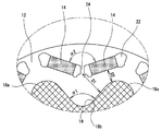
以下、回転電機のロータ10の構成について図面を参照して説明する。図1は、ロータ10の概略縦断面図である。図2は、ロータ10のY方向視図である。なお、図2では、ナット20については、その外形のみを二点鎖線で図示している。また、図3は、図2のA部拡大図である。
Hereinafter, the configuration of the
このロータ10は、回転電機、例えば、駆動源の一つとして電動車両に搭載される三相同期型回転電機等に用いられる。ロータ10は、ロータコア12と当該ロータコア12に埋め込まれる永久磁石14と、ロータ10に固着される回転軸16と、ロータコア12に軸力を付与するワッシャ18およびナット20と、を備えている。
The
ロータコア12は、その中央に軸孔が形成された略環状体である。ロータコア12は、複数の電磁鋼板(例えばケイ素鋼板等)を軸方向に積層してなる。ロータコア12の外周端近傍には、複数の磁石孔22が、周方向に間隔をあけて並んでいる。各磁石孔22は、軸方向に貫通しており、その内部には、ロータ10の磁極を構成する永久磁石14が配される。
The
本例において、永久磁石14は、V字状配置となっている。すなわち、一つの磁極15は、径方向外側に向かって広がるV字状に配された一対の永久磁石14で構成される。図2の例では、ロータ10は、8つの磁極15を構成する16個の永久磁石14を有している。各永久磁石14は、その断面形状が扁平な略長方形であり、その短軸方向(略ロータ径方向)に磁化されている。永久磁石14のうち、S磁極を構成する永久磁石14は、S極が、N磁極を構成する永久磁石14は、N極が、径方向外側になるように配されている。
In this example, the
V字状配置の永久磁石14を受け入れるため、磁石孔22も、V字状配置となっている。すなわち、ロータコア12には、径方向外側に向かって広がるV字状に配される一対の磁石孔22が、複数対(図示例では8対)、周方向に均等配置されている。この磁石孔22は、永久磁石14よりも長軸寸法が大きい略長方形となっている。したがって、永久磁石14を磁石孔22に挿入した際、当該永久磁石14の長軸方向両側には、空隙が形成される。この空隙は、一般に、フラックスバリアと呼ばれ、磁気的抵抗部として機能することで、ロータコアの磁気的特性を調整する。
The magnet holes 22 are also V-shaped in order to receive the V-shaped
また、同一磁極に属する二つの磁石孔22は、周方向に近接しており、両磁石孔22の間には、微小間隙部であるブリッジ部24が形成される。このブリッジ部24は、ロータコア12の中でも局所的に剛性が低下した低剛性部といえる。こうしたブリッジ部24(低剛性部)では、応力が集中しやすく、劣化や破損が生じやすい。そこで、ブリッジ部24への応力集中を緩和するために、ワッシャ18を特殊形状としているが、これについては、後述する。
Further, the two
なお、本例では、ブリッジ部24を、ロータコア12の一部としているが、当該ブリッジ部24は、ロータコア12を構成する積層鋼板とは、別部材で構成されてもよい。例えば、図4に示すように、一本に繋がった略V字の貫通孔23を形成するとともに、当該V字の谷部分に、図4において二点鎖線で示すようなブリッジ部材25を挿入するようにしてもよい。この場合、ブリッジ部材25の材質は、特に限定されないが、非磁性体であることが望ましい。
Although the
ロータコア12の軸孔には、回転軸16が挿通され、固着されている。回転軸16は、図示しない軸受を介して回転自在に軸支されており、ロータコア12と一体的に回転する。この回転軸16の途中には、径方向外側に張り出したフランジ26が形成されている。回転軸16に挿入されたロータコア12は、このフランジ26に押し当てられる。
The
また、回転軸16のうち、ロータコア12を挟んで、フランジ26の反対側付近の外周面には、雄ネジが形成されている。図1における太線は、雄ネジの形成箇所を示している。この雄ネジには、後述するように、ナット20が螺合される。なお、図面では、回転軸16を、中空の円筒状として図示しているが、回転軸16は、ロータコア12と同心に配され、断面円形の外周面を有するのであれば、その構成は、特に限定されない。したがって、回転軸16は、中実の丸棒状でもよいし、内部に冷媒流路が形成されてもよい。
A male screw is formed on the outer peripheral surface of the
ワッシャ18およびナット20は、フランジ26と協働して、ロータコア12の軸方向の動きを規制するとともに、ロータコア12に軸方向の圧縮力を付与する。ワッシャ18は、フランジ26と反対側の端部から、回転軸16に挿入され、ロータコア12の軸方向端面に当接する。ナット20は、同じく、フランジ26の反対側の端部から回転軸16に挿入され、回転軸16に形成された雄ネジに螺合される。そして、このナット20で締め付けることで、ロータコア12が、ワッシャ18とフランジ26で挟持され、軸方向の動きが規制されるとともに、軸方向の圧縮力(軸力)を受ける。
The
ここで、本明細書で開示するロータ10では、このロータコア12に付与する軸力を十分に確保しつつも、ロータコア12の局所的な劣化等を防止するために、ワッシャ18を特殊な形状としている。これについて、従来技術と比較して説明する。図9は、従来のロータ10の一例を示す図である。
Here, in the
ロータコア12に付与される軸力が低下すると、当然ながら、ロータコア12の固定力の低下を招く。また、軸力が低下すると、ロータコア12を構成する電磁鋼板間の隙間が大きくなり、当該隙間からの冷媒液の漏出等も招く。そのため、ロータコア12には、十分な軸力が付与されることが望まれる。
When the axial force applied to the
ロータコア12に付与する軸力を向上するためには、当然ながら、ナット20の締め付け力を増加させればよい。しかし、従来の構成では、ワッシャ18をナット20とほぼ同径の円環状としており、ワッシャ18は、ロータコア12の径方向内側1/3程度の面積でしか接触していなかった。そのため、ナット20の締め付け力を増加させた場合、当該径方向内側1/3程度の面積部分にのみ、大きな締め付け力(軸力)がかかることとなり、ロータコア12全体に十分な軸力を付与することは難しかった。
In order to improve the axial force applied to the
そこで、当然ながら、ワッシャ18の面積を増大させることも考えられる。ただし、磁気短絡防止や、永久磁石14の放熱等の観点から、ワッシャ18は、永久磁石14を覆わないことが望ましい。そこで、例えば、円環状のワッシャ18の外径を、図9において一点鎖線で示すように、磁石孔22の内周端近傍まで拡大させることも考えられる。かかる構成とすれば、ナット20の締め付け力を、広い面積に分散して伝達できるため、ロータコア12全体に、十分な軸力を付与することが可能となる。
Therefore, of course, increasing the area of the
しかし、円環状のワッシャ18の外径を単純に拡大した場合、局所的に剛性が低下したブリッジ部24の近傍に、力が付加されることになる。この場合、締め付け力の付与によりロータコア12内に生じる応力が、この剛性が低下したブリッジ部24に集中しやすくなる。その結果、ブリッジ部24の劣化や、破損といった別の問題を招く。
However, when the outer diameter of the
そこで、本明細書で開示するロータ10では、ワッシャ18を特殊な形状としている。すなわち、本例のワッシャ18の外周形状は、図2、図3に示すように、磁石孔22より径方向内側に位置するとともに、回転中心Oから外周端までの距離が、周方向に、周期的に変動する凹凸形状となっている。また、ワッシャ18は、図3に示すように、当該ワッシャ18の外周端からブリッジ部24までの距離D1が、当該ワッシャ18の外周端から磁石孔22までの距離D2以上となるような形状となっている。なお、ここで、距離D1、距離D2とは、いずれも、最短距離を意味する。例えば、「ワッシャ18の外周端から磁石孔22までの距離D2」とは、ワッシャ18の外周端と磁石孔22との間の間隙の幅が最も小さくなった箇所における当該間隙の幅を意味する。同様に、「ワッシャ18の外周端からブリッジ部24までの距離D1」とは、ワッシャ18の外周端と、ブリッジ部24との間の間隙の幅が最も小さくなった箇所における当該間隙の幅を意味する。
Therefore, in the
ワッシャ18の形状について、より具体的に説明すると、ワッシャ18の外周形状は、径方向外側に凸の円弧状である凸部18aと、径方向内側に凹の円弧状である凹部18bとが、周方向に交互に並ぶような、略花形、あるいは、角部が丸まった略歯車のような形状となっている。このワッシャ18の外周形状の凹凸の変動周期は、磁極15の配設ピッチ、または、低剛性部であるブリッジ部24の配設ピッチと同じである。本例では、磁極15およびブリッジ部24は、8つあり、その配設ピッチは、8/360=45度であるため、ワッシャ18の外周形状の凹凸は、45度の周期で変動している。
The shape of the
また、ワッシャ18は、回転中心からワッシャ18の外周端までの距離が最小となる凹部18bの中心点(以下「凹点19」という)が、ブリッジ部24と同一位相になるように、配されている。換言すれば、ワッシャ18は、凹点19と、ブリッジ部24とが、径方向に一直線に並ぶように配されている。
Further, the
したがって、ワッシャ18の外周形状は、略V字状に配された磁石孔22の内周端を径方向内側にオフセットした線を繋げた形状に類似している。ただし、ワッシャ18は、V字に相当する箇所の広がり角度α1が、磁石孔22の当該箇所における広がり角度α2よりも小さく、磁石孔22よりも径方向内側に深いV字を形成している。その結果、ワッシャ18の外周端からブリッジ部24までの距離D1が、ワッシャ18の外周端から磁石孔22までの距離D2以上となる。
Therefore, the outer peripheral shape of the
このように、ワッシャ18の外周端からブリッジ部24までの距離が大きくなることで、局所的に剛性が低下しているブリッジ部24近傍に力が付与されにくくなり、ブリッジ部24への応力の集中を緩和できる。そして、これにより、ブリッジ部24の劣化や損傷を効果的に抑制できる。一方で、ワッシャ18のうち、ブリッジ部24と位相がずれた箇所については、従来のロータ10よりも径方向外側に延びているため、ロータコア12の広範囲に軸力を付与できる。結果として、本例のワッシャ18によれば、ロータコア12に付与する軸力を十分に確保しつつも、ロータコア12の局所的な劣化等を防止することができる。
As described above, since the distance from the outer peripheral end of the
なお、ブリッジ部24への応力集中を緩和するためには、ワッシャ18の凹点19とブリッジ部24との位相を揃える必要がある。そのため、本明細書で開示するロータ10では、ワッシャ18とロータコア12の位相を揃えるために、ワッシャ18と回転軸16とをキー係合させている。すなわち、ワッシャ18の内周面に、径方向内側に突出するキー突起30を設けるとともに、回転軸16の外周面に、当該キー突起30を受け入れるキー溝32を設けている。そして、キー突起30が、キー溝32に嵌るようにワッシャ18を回転軸16に組み込むことで、ワッシャ18のロータコア12に対する位相が良好に規制される。
In order to reduce the stress concentration on the
なお、本例では、ワッシャ18にキー突起30を、回転軸16にキー溝32を設けているが、これらの組み合わせは逆でもよい。すなわち、回転軸16にキー突起を、ワッシャ18にキー溝を設けてもよい。また、キー溝32、キー突起30の個数は、適宜、変更されてもよい。
In this example, the
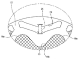
次に、ロータ10の他の例について説明する。図5は、他のロータ10の一例を示す図である。また、図6は、図5のB部拡大図である。このロータ10は、一つの磁極15が、逆三角形状に配された三つの永久磁石14a,14b(以下、二種類の永久磁石14a,14bを区別しないときは、添え字を省略する。後述の磁石孔についても同じ)で構成されている。すなわち、一つの磁極15は、径方向外側に向かって広がるV字状に配された一対の永久磁石14aと、当該一対の永久磁石14の外周端の間に配される一つの永久磁石14bと、で構成される。
Next, another example of the
ロータコア12には、この永久磁石14を受け入れるための磁石孔22が形成されている。一対の磁石孔22aは、径方向外側に向かって広がるV字状に配されている。ただし、この二つの磁石孔22aは、周方向に近接しておらず、二つの磁石孔22aそれぞれの内周側端部の間には、中間孔28が形成されている。中間孔28は、ロータコア12を軸方向に貫通する貫通孔である。この中間孔28は、磁気抵抗部として機能しており、当該中間孔28を設けることで、磁束の流れが整えられる。ここで、図6から明らかな通り、中間孔28と磁石孔22aとの間には、局所的に剛性が低下した微小間隙部であるブリッジ部24が形成されている。
Magnet holes 22 for receiving the
また、二つの磁石孔22aそれぞれの外周端の間には、周方向に延びる磁石孔22bが形成されている。この磁石孔22bの周方向両側には、一対の空隙孔29が形成されている。空隙孔29は、中間孔28と同様に、ロータコア12を軸方向に貫通する貫通孔であり、磁気抵抗部として機能する貫通孔である。この空隙孔29も、磁束の流れを整えるために設けられている。
Further, a
図5、図6に示す例においても、ロータコア12の軸方向端面には、ワッシャ18が配され、当該ワッシャ18は、ナット20(図5、図6では図示せず)の締め付け力により、ロータコア12に押し当てられている。このワッシャ18は、図2に示した例と同様に、磁石孔22より径方向内側に位置するとともに、回転中心Oから外周端までの距離が、周方向に、周期的に変動する凹凸形状となっている。また、ワッシャ18は、図6に示すように、当該ワッシャ18の外周端からブリッジ部24までの距離D1が、当該ワッシャ18の外周端から磁石孔22までの距離D2以上となるような形状となっている。
Also in the example shown in FIGS. 5 and 6, a
具体的に説明すると、ワッシャ18の外周形状は、径方向外側に凸の円弧状である凸部18aと、径方向内側に凹の円弧状である凹部18bとが、周方向に交互に並ぶような、略花形、あるいは、角部が丸まった略歯車のような形状となっている。このワッシャ18の外周形状の凹凸の変動周期は、磁極15の配設ピッチと同じである。
More specifically, the outer peripheral shape of the
また、ワッシャ18は、回転中心からワッシャ18の外周端までの距離が最小となる凹点19が、中間孔28の周方向中心と同一位相になるように、配されている。換言すれば、ワッシャ18は、凹点19と、中間孔28の周方向中心とが、径方向に一直線に並ぶように配されている。かかる構成とすることで、ブリッジ部24への応力の集中を緩和できる一方で、ロータコア12の広範囲に軸力を付与できる。
Further, the
なお、図5、図6の例では、凹部18bを、径方向内側に凹の略円弧状としているが、当該凹部18bは、図7に示すように、略周方向に延びる直線状としてもよい。かかる構成とすれば、図5、図6の場合に比べて、ワッシャ18の外周端からブリッジ部24までの距離D1を大きくでき、ひいては、ブリッジ部24への応力集中をより緩和できる。
In the examples of FIGS. 5 and 6, the
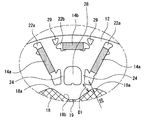
次に、ロータ10の他の例について説明する。図8は、他のロータ10の一例を示す図である。このロータ10は、一つの磁極15が、略周方向に長尺な、一つの永久磁石14で構成されている。図8の例では、ロータ10は、16個の磁極15、16個の永久磁石14を有している。
Next, another example of the
ロータコア12には、この永久磁石14を受け入れるための磁石孔22が形成されている。磁石孔22は、略周方向に長尺かつ扁平な略長方形であり、その長軸寸法は、永久磁石14の長軸寸法よりも大きくなっている。そして、周方向に隣接する二つの磁石孔22の間には、幅細の間隙部36が形成されている。この間隙部36は、上述したブリッジ部24と同様に、局所的に剛性が低下した低剛性部と言える。
Magnet holes 22 for receiving the
かかるロータコア12に密着するワッシャ18は、図2に示すワッシャ18と同様に、磁石孔22より径方向内側に位置するとともに、回転中心Oから外周端までの距離が、周方向に、周期的に変動する凹凸形状となっている。また、ワッシャ18は、図8に示すように、その外周端から間隙部36までの距離D1が、その外周端から磁石孔22までの距離D2以上となるような形状となっている。
Like the
具体的に説明すると、ワッシャ18の外周形状は、径方向外側に凸の円弧状である凸部18aと、径方向内側に凹の円弧状である凹部18bとが、周方向に交互に並ぶような、略花形、あるいは、角部が丸まった星型のような形状となっている。このワッシャ18の外周形状の凹凸の変動周期は、磁極15の配設ピッチと同じである。
More specifically, the outer peripheral shape of the
また、ワッシャ18は、回転中心Oからワッシャ18の外周端までの距離が最小となる凹部18bの周方向中心点(以下「凹点19」という)が、間隙部36と同一位相になるように、配されている。換言すれば、ワッシャ18は、凹点19と、間隙部36とが、径方向に一直線に並ぶように配されている。かかる構成とすることで、間隙部36への応力の集中を緩和できる一方で、ロータコア12の広範囲に軸力を付与できる。
Further, the
以上の説明から明らかな通り、本明細書で開示するロータ10によれば、十分な軸力を確保しつつ、低剛性部にかかる応力を軽減できる。なお、本明細書で開示した構成は、一例であり、ワッシャの外周端から低剛性部までの距離が、ワッシャの外周端から磁石孔までの距離以上であれば、その他の構成は、適宜、変更されてもよい。例えば、上述の説明では、ワッシャ18は、全て、角部が丸まった略歯車形状となっているが、角部が尖った略歯車形状としてもよい。ただし、応力の一極集中を避けるためには、ワッシャ18の外周形状は、極力、尖った角のない形状であることが望ましい。
As is clear from the above description, according to the
10 ロータ、12 ロータコア、14 永久磁石、15 磁極、16 回転軸、18 ワッシャ、19 凹点、20 ナット、22 磁石孔、23 貫通孔、24 ブリッジ部、25 ブリッジ部材、26 フランジ、28 中間孔、29 空隙孔、30 キー突起、32 キー溝、36 間隙部。
10 rotors, 12 rotor cores, 14 permanent magnets, 15 magnetic poles, 16 rotating shafts, 18 washers, 19 concave points, 20 nuts, 22 magnet holes, 23 through holes, 24 bridge parts, 25 bridge members, 26 flanges, 28 intermediate holes, 29 voids, 30 key protrusions, 32 key grooves, 36 gaps.
Claims (8)
前記磁石孔に配され、磁極を構成する複数の磁石と、
前記ロータコアの軸孔に固着された回転軸と、
前記ロータコアの軸方向端面に密着するワッシャであって、その外周端が前記磁石孔より径方向内側に位置するワッシャと、
前記回転軸に螺合され、前記ワッシャを前記ロータコアに押し付けるナットと、
を備え、
前記ロータコアには、貫通孔を形成したことで局所的に剛性が低下した低剛性部が、周方向に間隔をあけて複数存在しており、
前記ワッシャの外周形状は、回転中心から外周端までの距離が、周期的に変動する凹凸形状であり、
前記ワッシャの外周端から前記低剛性部までの距離は、前記ワッシャの外周端から前記磁石孔までの距離よりも大きい、
ことを特徴とする回転電機のロータ。 A substantially annular rotor core having an axial hole formed in the center, a plurality of through-hole magnet holes, the rotor core formed side by side in the circumferential direction,
A plurality of magnets which are arranged in the magnet holes and constitute magnetic poles,
A rotation shaft fixed to the shaft hole of the rotor core;
A washer that is in close contact with the axial end surface of the rotor core, the outer peripheral end of which is located radially inward of the magnet hole;
A nut that is screwed to the rotating shaft and presses the washer against the rotor core,
Equipped with
In the rotor core, a plurality of low-rigidity portions where the rigidity is locally reduced due to the formation of through-holes are present at intervals in the circumferential direction,
The outer peripheral shape of the washer is an uneven shape in which the distance from the center of rotation to the outer peripheral end changes periodically.
The distance from the outer peripheral end of the washer to the low rigidity portion is larger than the distance from the outer peripheral end of the washer to the magnet hole,
A rotor of a rotating electric machine characterized by the above.
前記ロータコアには、径方向外側に向かって広がるV字状に配されるとともに微小間隙部であるブリッジ部を介して周方向に隣接する一対の磁石孔が、周方向に、複数対、形成されており、
前記低剛性部は、前記ブリッジ部である、
ことを特徴とする回転電機のロータ。 The rotor of the rotating electric machine according to claim 1,
In the rotor core, a plurality of pairs of magnet holes, which are arranged in a V shape expanding outward in the radial direction and are adjacent to each other in the circumferential direction via a bridge portion which is a minute gap portion, are formed in the circumferential direction. And
The low-rigidity portion is the bridge portion,
A rotor of a rotating electric machine characterized by the above.
前記ロータコアには、略周方向に長尺な磁石孔が、周方向に、複数、形成されており、
前記低剛性部は、周方向に隣接する磁石孔間の間隙部である、
ことを特徴とする回転電機のロータ。 The rotor of the rotating electric machine according to claim 1,
In the rotor core, a plurality of magnet holes elongated in the circumferential direction are formed in the circumferential direction,
The low-rigidity portion is a gap portion between magnet holes adjacent to each other in the circumferential direction,
A rotor of a rotating electric machine characterized by the above.
前記ワッシャは、前記低剛性部と同一位相において、前記回転中心から外周端までの距離が、最小となるように配されている、ことを特徴とする回転電機のロータ。 The rotor of the rotary electric machine according to claim 2 or 3, wherein
The washer is arranged so that the distance from the rotation center to the outer peripheral end is minimized in the same phase as the low-rigidity portion, and the washer is arranged.
前記ロータコアには、周方向に隣接するとともに径方向外側に向かって広がるV字状に配された一対の磁石孔と、前記一対の磁石孔の間に形成された中間孔と、を含む貫通孔の組が、周方向に、複数組、形成されており、
前記低剛性部は、前記磁石孔と前記中間孔との間の微小間隙部であるブリッジ部である、
ことを特徴とする回転電機のロータ。 The rotor of the rotating electric machine according to claim 1,
The rotor core includes a through hole including a pair of V-shaped magnet holes that are adjacent to each other in the circumferential direction and spread outward in the radial direction, and an intermediate hole formed between the pair of magnet holes. A plurality of sets are formed in the circumferential direction,
The low-rigidity portion is a bridge portion that is a minute gap portion between the magnet hole and the intermediate hole,
A rotor of a rotating electric machine characterized by the above.
前記ワッシャは、前記中間孔と同一位相において、前記回転中心から外周端までの距離が、最小となるように配されている、ことを特徴とする回転電機のロータ。 The rotor of the rotating electric machine according to claim 5,
The washer is arranged so that the distance from the center of rotation to the outer peripheral edge is minimized in the same phase as that of the intermediate hole.
前記ワッシャの外周形状は、角部が丸まった歯車形である、ことを特徴とする回転電機のロータ。 A rotor for a rotating electric machine according to any one of claims 1 to 6, wherein:
The rotor of a rotary electric machine is characterized in that an outer peripheral shape of the washer is a gear shape with rounded corners.
前記ワッシャの内周面および前記回転軸の外周面の一方には、他方に向かって突出するキー突起が形成されており、
前記ワッシャの内周面および前記回転軸の外周面の前記他方には、前記キー突起を受け入れるキー溝が形成されている、
ことを特徴とする回転電機のロータ。
A rotor for a rotating electric machine according to any one of claims 1 to 7, wherein:
One of the inner peripheral surface of the washer and the outer peripheral surface of the rotating shaft is formed with a key protrusion protruding toward the other,
A key groove for receiving the key projection is formed on the other of the inner peripheral surface of the washer and the outer peripheral surface of the rotating shaft.
A rotor of a rotating electric machine characterized by the above.
Priority Applications (6)
| Application Number | Priority Date | Filing Date | Title |
|---|---|---|---|
| JP2017051869A JP6740940B2 (en) | 2017-03-16 | 2017-03-16 | Rotating electric machine rotor |
| BR102018005069A BR102018005069A2 (en) | 2017-03-16 | 2018-03-14 | rotor for rotary electric machine |
| KR1020180029813A KR102006362B1 (en) | 2017-03-16 | 2018-03-14 | Rotor for rotary electric machine |
| RU2018109123A RU2685244C1 (en) | 2017-03-16 | 2018-03-14 | Rotor for electric rotating machine |
| US15/921,986 US10666101B2 (en) | 2017-03-16 | 2018-03-15 | Rotor for rotary electric machine |
| EP18162254.9A EP3376641B1 (en) | 2017-03-16 | 2018-03-16 | Rotor for rotary electric machine |
Applications Claiming Priority (1)
| Application Number | Priority Date | Filing Date | Title |
|---|---|---|---|
| JP2017051869A JP6740940B2 (en) | 2017-03-16 | 2017-03-16 | Rotating electric machine rotor |
Publications (2)
| Publication Number | Publication Date |
|---|---|
| JP2018157669A JP2018157669A (en) | 2018-10-04 |
| JP6740940B2 true JP6740940B2 (en) | 2020-08-19 |
Family
ID=61691337
Family Applications (1)
| Application Number | Title | Priority Date | Filing Date |
|---|---|---|---|
| JP2017051869A Active JP6740940B2 (en) | 2017-03-16 | 2017-03-16 | Rotating electric machine rotor |
Country Status (6)
| Country | Link |
|---|---|
| US (1) | US10666101B2 (en) |
| EP (1) | EP3376641B1 (en) |
| JP (1) | JP6740940B2 (en) |
| KR (1) | KR102006362B1 (en) |
| BR (1) | BR102018005069A2 (en) |
| RU (1) | RU2685244C1 (en) |
Families Citing this family (12)
| Publication number | Priority date | Publication date | Assignee | Title |
|---|---|---|---|---|
| JPWO2020067348A1 (en) * | 2018-09-28 | 2021-08-30 | 本田技研工業株式会社 | Rotating electric rotor |
| JP7112340B2 (en) * | 2019-01-21 | 2022-08-03 | 本田技研工業株式会社 | Rotor of rotating electric machine and rotating electric machine |
| DE102019113596A1 (en) * | 2019-05-22 | 2020-11-26 | Schaeffler Technologies AG & Co. KG | Electrical machine with a fastening of several rotor laminations on a rotor shaft that enables axial tolerance compensation |
| DE102019215324A1 (en) * | 2019-10-07 | 2021-04-08 | Zf Friedrichshafen Ag | Rotor of a permanent magnet excited electrical machine |
| US20220302781A1 (en) * | 2020-03-31 | 2022-09-22 | Aisin Corporation | Rotor |
| WO2021205713A1 (en) * | 2020-04-07 | 2021-10-14 | 三菱電機株式会社 | Rotating electric machine |
| DE102020111215A1 (en) * | 2020-04-24 | 2021-10-28 | Schaeffler Technologies AG & Co. KG | Rotor assembly with rotational securing of at least one disk element; as well as electric machine |
| DE102020210497A1 (en) | 2020-08-19 | 2022-02-24 | Zf Friedrichshafen Ag | Rotor of a permanently excited electrical machine |
| DE102020214046A1 (en) * | 2020-11-09 | 2022-05-12 | Valeo Siemens Eautomotive Germany Gmbh | Rotor for an electrical machine with improved axial securing of a laminated rotor core |
| CN112865368A (en) * | 2021-02-26 | 2021-05-28 | 合肥巨一动力系统有限公司 | Rotor punching sheet structure |
| CN113675980B (en) * | 2021-06-28 | 2022-11-01 | 东风汽车集团股份有限公司 | Electric automobile and driving motor and power assembly thereof |
| WO2023074307A1 (en) * | 2021-10-29 | 2023-05-04 | ダイキン工業株式会社 | Rotor, motor, compressor, and air-conditioning device |
Family Cites Families (21)
| Publication number | Priority date | Publication date | Assignee | Title |
|---|---|---|---|---|
| SU1077015A1 (en) * | 1982-12-07 | 1984-02-29 | Всесоюзный Научно-Исследовательский Институт Электромашиностроения | Rotor or electric machine |
| SU1758785A1 (en) * | 1990-02-19 | 1992-08-30 | Московский агрегатный завод "Дзержинец" | Rotor of electric machine |
| JP4365194B2 (en) * | 2003-08-28 | 2009-11-18 | トヨタ自動車株式会社 | Permanent magnet motor |
| JP2005130688A (en) * | 2003-10-01 | 2005-05-19 | Asmo Co Ltd | Magnets-embedded rotor and electric motor |
| JP4850528B2 (en) * | 2006-02-08 | 2012-01-11 | トヨタ自動車株式会社 | Manufacturing method of rotor |
| US8405270B2 (en) * | 2007-05-07 | 2013-03-26 | Panasonic Corporation | Permanent magnet buried type electric motor |
| JP4424385B2 (en) * | 2007-07-20 | 2010-03-03 | トヨタ自動車株式会社 | Rotating electric machine |
| EP2169807B1 (en) * | 2008-09-30 | 2011-12-21 | Siemens Aktiengesellschaft | Laminated sheet package assembly with claw fastener end plate |
| DE102009047677A1 (en) * | 2009-12-08 | 2011-06-09 | Robert Bosch Gmbh | Rotor for electrical machine e.g. generator, in hybrid drive assembly, has shaft and balancing disks that are electrically and/or mechanically isolated with respect to permanent magnets, where disks are arranged at distance from magnets |
| JP5310872B2 (en) * | 2009-12-23 | 2013-10-09 | トヨタ自動車株式会社 | Rotor |
| JP5879848B2 (en) * | 2010-12-14 | 2016-03-08 | 富士電機株式会社 | Rotor for interior magnet type rotary electric machine |
| JP5353917B2 (en) * | 2011-02-03 | 2013-11-27 | トヨタ自動車株式会社 | Rotating machine rotor |
| US8970085B2 (en) * | 2011-04-01 | 2015-03-03 | Denso Corporation | Rotor for electric rotating machine and method of manufacturing the same |
| WO2012169043A1 (en) * | 2011-06-09 | 2012-12-13 | トヨタ自動車株式会社 | Rotor for rotating electrical machine, rotating electric machine, and method for producing rotor for rotating electrical machine |
| CN202309282U (en) * | 2011-11-09 | 2012-07-04 | 大洋电机新动力科技有限公司 | Embedded permanent magnet synchronous rotor assembly |
| JP2014075892A (en) * | 2012-10-03 | 2014-04-24 | Toyota Motor Corp | Rotor of rotary electric machine |
| JP2015056911A (en) * | 2013-09-10 | 2015-03-23 | トヨタ自動車株式会社 | Rotor and rotary electric machine having the same |
| JP2015100227A (en) * | 2013-11-20 | 2015-05-28 | トヨタ自動車株式会社 | Rotary electric machine rotor |
| JP5818949B2 (en) * | 2014-07-03 | 2015-11-18 | 三菱電機株式会社 | Rotating electric machine |
| JP6162656B2 (en) * | 2014-07-09 | 2017-07-12 | 株式会社三井ハイテック | Rotor laminated iron core and manufacturing method thereof |
| JP6365470B2 (en) * | 2015-09-03 | 2018-08-01 | トヨタ自動車株式会社 | Rotor for rotating electrical machines |
-
2017
- 2017-03-16 JP JP2017051869A patent/JP6740940B2/en active Active
-
2018
- 2018-03-14 BR BR102018005069A patent/BR102018005069A2/en not_active Application Discontinuation
- 2018-03-14 RU RU2018109123A patent/RU2685244C1/en active
- 2018-03-14 KR KR1020180029813A patent/KR102006362B1/en active IP Right Grant
- 2018-03-15 US US15/921,986 patent/US10666101B2/en active Active
- 2018-03-16 EP EP18162254.9A patent/EP3376641B1/en active Active
Also Published As
| Publication number | Publication date |
|---|---|
| EP3376641B1 (en) | 2021-03-03 |
| RU2685244C1 (en) | 2019-04-17 |
| US10666101B2 (en) | 2020-05-26 |
| JP2018157669A (en) | 2018-10-04 |
| KR102006362B1 (en) | 2019-08-01 |
| EP3376641A1 (en) | 2018-09-19 |
| US20180269735A1 (en) | 2018-09-20 |
| KR20180106922A (en) | 2018-10-01 |
| BR102018005069A2 (en) | 2018-10-30 |
Similar Documents
| Publication | Publication Date | Title |
|---|---|---|
| JP6740940B2 (en) | Rotating electric machine rotor | |
| JP5310872B2 (en) | Rotor | |
| JP6443446B2 (en) | Permanent magnet type rotating electrical machine rotor | |
| JP2007028868A (en) | Stator for rotary electric machine | |
| JP2007104819A (en) | Rotating electric machine | |
| JP7063637B2 (en) | Rotating machine rotor | |
| JP2006238678A (en) | Magnetic material, rotor, electric motor | |
| JP2007336671A (en) | Rotor of permanent magnet rotary electric machine | |
| JP6539539B2 (en) | Axial gap type electric rotating machine | |
| JPWO2011125308A1 (en) | Permanent magnet type rotating electrical machine rotor | |
| JP2012050226A (en) | Rotor of permanent magnet type rotary electric machine | |
| JP2004248442A (en) | Dc brushless motor | |
| JP2020058151A (en) | Rotor core | |
| JP7381304B2 (en) | A rotor with end plates arranged on the end face of the rotor core and an electric motor with the rotor | |
| JP2018057155A (en) | Rotator of rotating electrical machine | |
| WO2013105236A1 (en) | Embedded magnet rotor | |
| JP2017050926A (en) | Rotary electric machine | |
| JP6165622B2 (en) | Rotating electric machine rotor and rotating electric machine equipped with the same | |
| JP4244325B2 (en) | Rotating electrical machine rotor | |
| WO2020250647A1 (en) | Rotor and rotating electric machine | |
| JP2015104238A (en) | Double stator type rotary electric machine | |
| WO2022158426A1 (en) | Rotor provided with end plate and electric motor | |
| JP6210160B2 (en) | Synchronous reluctance rotating electric machine | |
| JP2012152055A (en) | Rotary electric machine and wind power generation system | |
| WO2022074898A1 (en) | Rotary electric machine |
Legal Events
| Date | Code | Title | Description |
|---|---|---|---|
| A621 | Written request for application examination |
Free format text: JAPANESE INTERMEDIATE CODE: A621 Effective date: 20190620 |
|
| TRDD | Decision of grant or rejection written | ||
| A977 | Report on retrieval |
Free format text: JAPANESE INTERMEDIATE CODE: A971007 Effective date: 20200610 |
|
| A01 | Written decision to grant a patent or to grant a registration (utility model) |
Free format text: JAPANESE INTERMEDIATE CODE: A01 Effective date: 20200623 |
|
| A61 | First payment of annual fees (during grant procedure) |
Free format text: JAPANESE INTERMEDIATE CODE: A61 Effective date: 20200706 |
|
| R151 | Written notification of patent or utility model registration |
Ref document number: 6740940 Country of ref document: JP Free format text: JAPANESE INTERMEDIATE CODE: R151 |