JP6643252B2 - Nebulizer - Google Patents
Nebulizer Download PDFInfo
- Publication number
- JP6643252B2 JP6643252B2 JP2016566222A JP2016566222A JP6643252B2 JP 6643252 B2 JP6643252 B2 JP 6643252B2 JP 2016566222 A JP2016566222 A JP 2016566222A JP 2016566222 A JP2016566222 A JP 2016566222A JP 6643252 B2 JP6643252 B2 JP 6643252B2
- Authority
- JP
- Japan
- Prior art keywords
- nebulizer
- locking
- container
- display device
- housing part
- Prior art date
- Legal status (The legal status is an assumption and is not a legal conclusion. Google has not performed a legal analysis and makes no representation as to the accuracy of the status listed.)
- Active
Links
- 239000006199 nebulizer Substances 0.000 title claims description 236
- 230000004913 activation Effects 0.000 claims description 122
- 230000000903 blocking effect Effects 0.000 claims description 64
- 239000012530 fluid Substances 0.000 claims description 42
- 230000005540 biological transmission Effects 0.000 claims description 22
- 238000000034 method Methods 0.000 claims description 17
- 230000008569 process Effects 0.000 claims description 16
- 238000005507 spraying Methods 0.000 claims description 16
- 230000007246 mechanism Effects 0.000 claims description 9
- 238000007906 compression Methods 0.000 claims description 4
- 230000006835 compression Effects 0.000 claims description 4
- 238000006073 displacement reaction Methods 0.000 claims description 3
- 238000001994 activation Methods 0.000 description 121
- 230000037431 insertion Effects 0.000 description 38
- 238000003780 insertion Methods 0.000 description 38
- 239000000243 solution Substances 0.000 description 20
- 230000036961 partial effect Effects 0.000 description 15
- 238000005273 aeration Methods 0.000 description 9
- 239000000443 aerosol Substances 0.000 description 7
- 230000003213 activating effect Effects 0.000 description 6
- 239000003570 air Substances 0.000 description 6
- 239000011888 foil Substances 0.000 description 6
- 238000003825 pressing Methods 0.000 description 6
- 238000005553 drilling Methods 0.000 description 5
- LFQSCWFLJHTTHZ-UHFFFAOYSA-N Ethanol Chemical compound CCO LFQSCWFLJHTTHZ-UHFFFAOYSA-N 0.000 description 4
- 230000008901 benefit Effects 0.000 description 4
- 239000003814 drug Substances 0.000 description 4
- 230000001681 protective effect Effects 0.000 description 4
- 230000000717 retained effect Effects 0.000 description 4
- 239000007788 liquid Substances 0.000 description 3
- 239000000203 mixture Substances 0.000 description 3
- 239000008194 pharmaceutical composition Substances 0.000 description 3
- 239000000843 powder Substances 0.000 description 3
- 239000003380 propellant Substances 0.000 description 3
- 230000001012 protector Effects 0.000 description 3
- 238000009423 ventilation Methods 0.000 description 3
- 238000005452 bending Methods 0.000 description 2
- 230000008859 change Effects 0.000 description 2
- 238000001514 detection method Methods 0.000 description 2
- 238000004146 energy storage Methods 0.000 description 2
- 238000009472 formulation Methods 0.000 description 2
- 239000008177 pharmaceutical agent Substances 0.000 description 2
- 230000009467 reduction Effects 0.000 description 2
- 230000002829 reductive effect Effects 0.000 description 2
- 230000002441 reversible effect Effects 0.000 description 2
- 238000012546 transfer Methods 0.000 description 2
- 239000013543 active substance Substances 0.000 description 1
- 238000004026 adhesive bonding Methods 0.000 description 1
- 239000012080 ambient air Substances 0.000 description 1
- 239000007864 aqueous solution Substances 0.000 description 1
- 238000005219 brazing Methods 0.000 description 1
- 238000006243 chemical reaction Methods 0.000 description 1
- 238000004040 coloring Methods 0.000 description 1
- 238000004891 communication Methods 0.000 description 1
- 238000002788 crimping Methods 0.000 description 1
- 230000001419 dependent effect Effects 0.000 description 1
- 230000000994 depressogenic effect Effects 0.000 description 1
- 229940079593 drug Drugs 0.000 description 1
- 238000007731 hot pressing Methods 0.000 description 1
- 238000001746 injection moulding Methods 0.000 description 1
- 238000004519 manufacturing process Methods 0.000 description 1
- 239000000463 material Substances 0.000 description 1
- 239000002184 metal Substances 0.000 description 1
- 229940071648 metered dose inhaler Drugs 0.000 description 1
- 230000004048 modification Effects 0.000 description 1
- 238000012986 modification Methods 0.000 description 1
- 239000012457 nonaqueous media Substances 0.000 description 1
- 239000002245 particle Substances 0.000 description 1
- 239000007971 pharmaceutical suspension Substances 0.000 description 1
- 239000011148 porous material Substances 0.000 description 1
- 238000005086 pumping Methods 0.000 description 1
- 239000002994 raw material Substances 0.000 description 1
- 230000003014 reinforcing effect Effects 0.000 description 1
- 230000004044 response Effects 0.000 description 1
- 239000002904 solvent Substances 0.000 description 1
- 239000007921 spray Substances 0.000 description 1
- 239000000126 substance Substances 0.000 description 1
- 230000001960 triggered effect Effects 0.000 description 1
- 238000003466 welding Methods 0.000 description 1
Images


Classifications
-
- A—HUMAN NECESSITIES
- A61—MEDICAL OR VETERINARY SCIENCE; HYGIENE
- A61M—DEVICES FOR INTRODUCING MEDIA INTO, OR ONTO, THE BODY; DEVICES FOR TRANSDUCING BODY MEDIA OR FOR TAKING MEDIA FROM THE BODY; DEVICES FOR PRODUCING OR ENDING SLEEP OR STUPOR
- A61M15/00—Inhalators
- A61M15/0065—Inhalators with dosage or measuring devices
-
- A—HUMAN NECESSITIES
- A61—MEDICAL OR VETERINARY SCIENCE; HYGIENE
- A61M—DEVICES FOR INTRODUCING MEDIA INTO, OR ONTO, THE BODY; DEVICES FOR TRANSDUCING BODY MEDIA OR FOR TAKING MEDIA FROM THE BODY; DEVICES FOR PRODUCING OR ENDING SLEEP OR STUPOR
- A61M11/00—Sprayers or atomisers specially adapted for therapeutic purposes
- A61M11/006—Sprayers or atomisers specially adapted for therapeutic purposes operated by applying mechanical pressure to the liquid to be sprayed or atomised
- A61M11/007—Syringe-type or piston-type sprayers or atomisers
-
- A—HUMAN NECESSITIES
- A61—MEDICAL OR VETERINARY SCIENCE; HYGIENE
- A61M—DEVICES FOR INTRODUCING MEDIA INTO, OR ONTO, THE BODY; DEVICES FOR TRANSDUCING BODY MEDIA OR FOR TAKING MEDIA FROM THE BODY; DEVICES FOR PRODUCING OR ENDING SLEEP OR STUPOR
- A61M15/00—Inhalators
-
- A—HUMAN NECESSITIES
- A61—MEDICAL OR VETERINARY SCIENCE; HYGIENE
- A61M—DEVICES FOR INTRODUCING MEDIA INTO, OR ONTO, THE BODY; DEVICES FOR TRANSDUCING BODY MEDIA OR FOR TAKING MEDIA FROM THE BODY; DEVICES FOR PRODUCING OR ENDING SLEEP OR STUPOR
- A61M15/00—Inhalators
- A61M15/0001—Details of inhalators; Constructional features thereof
- A61M15/0021—Mouthpieces therefor
- A61M15/0025—Mouthpieces therefor with caps
- A61M15/0026—Hinged caps
-
- A—HUMAN NECESSITIES
- A61—MEDICAL OR VETERINARY SCIENCE; HYGIENE
- A61M—DEVICES FOR INTRODUCING MEDIA INTO, OR ONTO, THE BODY; DEVICES FOR TRANSDUCING BODY MEDIA OR FOR TAKING MEDIA FROM THE BODY; DEVICES FOR PRODUCING OR ENDING SLEEP OR STUPOR
- A61M15/00—Inhalators
- A61M15/0028—Inhalators using prepacked dosages, one for each application, e.g. capsules to be perforated or broken-up
- A61M15/003—Inhalators using prepacked dosages, one for each application, e.g. capsules to be perforated or broken-up using capsules, e.g. to be perforated or broken-up
- A61M15/0033—Details of the piercing or cutting means
- A61M15/0035—Piercing means
- A61M15/0036—Piercing means hollow piercing means
-
- A—HUMAN NECESSITIES
- A61—MEDICAL OR VETERINARY SCIENCE; HYGIENE
- A61M—DEVICES FOR INTRODUCING MEDIA INTO, OR ONTO, THE BODY; DEVICES FOR TRANSDUCING BODY MEDIA OR FOR TAKING MEDIA FROM THE BODY; DEVICES FOR PRODUCING OR ENDING SLEEP OR STUPOR
- A61M15/00—Inhalators
- A61M15/0028—Inhalators using prepacked dosages, one for each application, e.g. capsules to be perforated or broken-up
- A61M15/003—Inhalators using prepacked dosages, one for each application, e.g. capsules to be perforated or broken-up using capsules, e.g. to be perforated or broken-up
- A61M15/0033—Details of the piercing or cutting means
- A61M15/004—Details of the piercing or cutting means with fixed piercing or cutting means
-
- A—HUMAN NECESSITIES
- A61—MEDICAL OR VETERINARY SCIENCE; HYGIENE
- A61M—DEVICES FOR INTRODUCING MEDIA INTO, OR ONTO, THE BODY; DEVICES FOR TRANSDUCING BODY MEDIA OR FOR TAKING MEDIA FROM THE BODY; DEVICES FOR PRODUCING OR ENDING SLEEP OR STUPOR
- A61M15/00—Inhalators
- A61M15/0028—Inhalators using prepacked dosages, one for each application, e.g. capsules to be perforated or broken-up
- A61M15/003—Inhalators using prepacked dosages, one for each application, e.g. capsules to be perforated or broken-up using capsules, e.g. to be perforated or broken-up
- A61M15/0033—Details of the piercing or cutting means
- A61M15/0041—Details of the piercing or cutting means with movable piercing or cutting means
-
- A—HUMAN NECESSITIES
- A61—MEDICAL OR VETERINARY SCIENCE; HYGIENE
- A61M—DEVICES FOR INTRODUCING MEDIA INTO, OR ONTO, THE BODY; DEVICES FOR TRANSDUCING BODY MEDIA OR FOR TAKING MEDIA FROM THE BODY; DEVICES FOR PRODUCING OR ENDING SLEEP OR STUPOR
- A61M15/00—Inhalators
- A61M15/0065—Inhalators with dosage or measuring devices
- A61M15/0068—Indicating or counting the number of dispensed doses or of remaining doses
- A61M15/007—Mechanical counters
- A61M15/0071—Mechanical counters having a display or indicator
- A61M15/0073—Mechanical counters having a display or indicator on a ring
-
- A—HUMAN NECESSITIES
- A61—MEDICAL OR VETERINARY SCIENCE; HYGIENE
- A61M—DEVICES FOR INTRODUCING MEDIA INTO, OR ONTO, THE BODY; DEVICES FOR TRANSDUCING BODY MEDIA OR FOR TAKING MEDIA FROM THE BODY; DEVICES FOR PRODUCING OR ENDING SLEEP OR STUPOR
- A61M15/00—Inhalators
- A61M15/0065—Inhalators with dosage or measuring devices
- A61M15/0068—Indicating or counting the number of dispensed doses or of remaining doses
- A61M15/0081—Locking means
-
- B—PERFORMING OPERATIONS; TRANSPORTING
- B05—SPRAYING OR ATOMISING IN GENERAL; APPLYING FLUENT MATERIALS TO SURFACES, IN GENERAL
- B05B—SPRAYING APPARATUS; ATOMISING APPARATUS; NOZZLES
- B05B11/00—Single-unit hand-held apparatus in which flow of contents is produced by the muscular force of the operator at the moment of use
- B05B11/01—Single-unit hand-held apparatus in which flow of contents is produced by the muscular force of the operator at the moment of use characterised by the means producing the flow
- B05B11/10—Pump arrangements for transferring the contents from the container to a pump chamber by a sucking effect and forcing the contents out through the dispensing nozzle
- B05B11/1042—Components or details
- B05B11/108—Means for counting the number of dispensing strokes
-
- G—PHYSICS
- G06—COMPUTING; CALCULATING OR COUNTING
- G06M—COUNTING MECHANISMS; COUNTING OF OBJECTS NOT OTHERWISE PROVIDED FOR
- G06M3/00—Counters with additional facilities
- G06M3/02—Counters with additional facilities for performing an operation at a predetermined value of the count, e.g. arresting a machine
- G06M3/021—Counters with additional facilities for performing an operation at a predetermined value of the count, e.g. arresting a machine with drums type indicating means
- G06M3/022—Counters with additional facilities for performing an operation at a predetermined value of the count, e.g. arresting a machine with drums type indicating means by subtracting
-
- A—HUMAN NECESSITIES
- A61—MEDICAL OR VETERINARY SCIENCE; HYGIENE
- A61M—DEVICES FOR INTRODUCING MEDIA INTO, OR ONTO, THE BODY; DEVICES FOR TRANSDUCING BODY MEDIA OR FOR TAKING MEDIA FROM THE BODY; DEVICES FOR PRODUCING OR ENDING SLEEP OR STUPOR
- A61M15/00—Inhalators
- A61M15/0001—Details of inhalators; Constructional features thereof
- A61M15/0021—Mouthpieces therefor
-
- A—HUMAN NECESSITIES
- A61—MEDICAL OR VETERINARY SCIENCE; HYGIENE
- A61M—DEVICES FOR INTRODUCING MEDIA INTO, OR ONTO, THE BODY; DEVICES FOR TRANSDUCING BODY MEDIA OR FOR TAKING MEDIA FROM THE BODY; DEVICES FOR PRODUCING OR ENDING SLEEP OR STUPOR
- A61M2202/00—Special media to be introduced, removed or treated
- A61M2202/0007—Special media to be introduced, removed or treated introduced into the body
-
- A—HUMAN NECESSITIES
- A61—MEDICAL OR VETERINARY SCIENCE; HYGIENE
- A61M—DEVICES FOR INTRODUCING MEDIA INTO, OR ONTO, THE BODY; DEVICES FOR TRANSDUCING BODY MEDIA OR FOR TAKING MEDIA FROM THE BODY; DEVICES FOR PRODUCING OR ENDING SLEEP OR STUPOR
- A61M2202/00—Special media to be introduced, removed or treated
- A61M2202/04—Liquids
- A61M2202/0468—Liquids non-physiological
-
- A—HUMAN NECESSITIES
- A61—MEDICAL OR VETERINARY SCIENCE; HYGIENE
- A61M—DEVICES FOR INTRODUCING MEDIA INTO, OR ONTO, THE BODY; DEVICES FOR TRANSDUCING BODY MEDIA OR FOR TAKING MEDIA FROM THE BODY; DEVICES FOR PRODUCING OR ENDING SLEEP OR STUPOR
- A61M2205/00—General characteristics of the apparatus
- A61M2205/12—General characteristics of the apparatus with interchangeable cassettes forming partially or totally the fluid circuit
-
- A—HUMAN NECESSITIES
- A61—MEDICAL OR VETERINARY SCIENCE; HYGIENE
- A61M—DEVICES FOR INTRODUCING MEDIA INTO, OR ONTO, THE BODY; DEVICES FOR TRANSDUCING BODY MEDIA OR FOR TAKING MEDIA FROM THE BODY; DEVICES FOR PRODUCING OR ENDING SLEEP OR STUPOR
- A61M2205/00—General characteristics of the apparatus
- A61M2205/27—General characteristics of the apparatus preventing use
- A61M2205/273—General characteristics of the apparatus preventing use preventing reuse, e.g. of disposables
-
- A—HUMAN NECESSITIES
- A61—MEDICAL OR VETERINARY SCIENCE; HYGIENE
- A61M—DEVICES FOR INTRODUCING MEDIA INTO, OR ONTO, THE BODY; DEVICES FOR TRANSDUCING BODY MEDIA OR FOR TAKING MEDIA FROM THE BODY; DEVICES FOR PRODUCING OR ENDING SLEEP OR STUPOR
- A61M2205/00—General characteristics of the apparatus
- A61M2205/27—General characteristics of the apparatus preventing use
- A61M2205/276—General characteristics of the apparatus preventing use preventing unwanted use
-
- A—HUMAN NECESSITIES
- A61—MEDICAL OR VETERINARY SCIENCE; HYGIENE
- A61M—DEVICES FOR INTRODUCING MEDIA INTO, OR ONTO, THE BODY; DEVICES FOR TRANSDUCING BODY MEDIA OR FOR TAKING MEDIA FROM THE BODY; DEVICES FOR PRODUCING OR ENDING SLEEP OR STUPOR
- A61M2205/00—General characteristics of the apparatus
- A61M2205/58—Means for facilitating use, e.g. by people with impaired vision
- A61M2205/583—Means for facilitating use, e.g. by people with impaired vision by visual feedback
-
- A—HUMAN NECESSITIES
- A61—MEDICAL OR VETERINARY SCIENCE; HYGIENE
- A61M—DEVICES FOR INTRODUCING MEDIA INTO, OR ONTO, THE BODY; DEVICES FOR TRANSDUCING BODY MEDIA OR FOR TAKING MEDIA FROM THE BODY; DEVICES FOR PRODUCING OR ENDING SLEEP OR STUPOR
- A61M2205/00—General characteristics of the apparatus
- A61M2205/58—Means for facilitating use, e.g. by people with impaired vision
- A61M2205/586—Ergonomic details therefor, e.g. specific ergonomics for left or right-handed users
-
- A—HUMAN NECESSITIES
- A61—MEDICAL OR VETERINARY SCIENCE; HYGIENE
- A61M—DEVICES FOR INTRODUCING MEDIA INTO, OR ONTO, THE BODY; DEVICES FOR TRANSDUCING BODY MEDIA OR FOR TAKING MEDIA FROM THE BODY; DEVICES FOR PRODUCING OR ENDING SLEEP OR STUPOR
- A61M2207/00—Methods of manufacture, assembly or production
- A61M2207/10—Device therefor
-
- A—HUMAN NECESSITIES
- A61—MEDICAL OR VETERINARY SCIENCE; HYGIENE
- A61M—DEVICES FOR INTRODUCING MEDIA INTO, OR ONTO, THE BODY; DEVICES FOR TRANSDUCING BODY MEDIA OR FOR TAKING MEDIA FROM THE BODY; DEVICES FOR PRODUCING OR ENDING SLEEP OR STUPOR
- A61M2209/00—Ancillary equipment
- A61M2209/06—Packaging for specific medical equipment
-
- B—PERFORMING OPERATIONS; TRANSPORTING
- B05—SPRAYING OR ATOMISING IN GENERAL; APPLYING FLUENT MATERIALS TO SURFACES, IN GENERAL
- B05B—SPRAYING APPARATUS; ATOMISING APPARATUS; NOZZLES
- B05B11/00—Single-unit hand-held apparatus in which flow of contents is produced by the muscular force of the operator at the moment of use
- B05B11/0005—Components or details
- B05B11/0037—Containers
- B05B11/0054—Cartridges, i.e. containers specially designed for easy attachment to or easy removal from the rest of the sprayer
-
- B—PERFORMING OPERATIONS; TRANSPORTING
- B65—CONVEYING; PACKING; STORING; HANDLING THIN OR FILAMENTARY MATERIAL
- B65D—CONTAINERS FOR STORAGE OR TRANSPORT OF ARTICLES OR MATERIALS, e.g. BAGS, BARRELS, BOTTLES, BOXES, CANS, CARTONS, CRATES, DRUMS, JARS, TANKS, HOPPERS, FORWARDING CONTAINERS; ACCESSORIES, CLOSURES, OR FITTINGS THEREFOR; PACKAGING ELEMENTS; PACKAGES
- B65D83/00—Containers or packages with special means for dispensing contents
-
- G—PHYSICS
- G06—COMPUTING; CALCULATING OR COUNTING
- G06M—COUNTING MECHANISMS; COUNTING OF OBJECTS NOT OTHERWISE PROVIDED FOR
- G06M1/00—Design features of general application
- G06M1/02—Housing
Landscapes
- Health & Medical Sciences (AREA)
- Engineering & Computer Science (AREA)
- Life Sciences & Earth Sciences (AREA)
- Anesthesiology (AREA)
- Biomedical Technology (AREA)
- Heart & Thoracic Surgery (AREA)
- Hematology (AREA)
- Animal Behavior & Ethology (AREA)
- General Health & Medical Sciences (AREA)
- Public Health (AREA)
- Veterinary Medicine (AREA)
- Bioinformatics & Cheminformatics (AREA)
- Pulmonology (AREA)
- Biophysics (AREA)
- Mechanical Engineering (AREA)
- Physics & Mathematics (AREA)
- General Physics & Mathematics (AREA)
- Theoretical Computer Science (AREA)
- Containers And Packaging Bodies Having A Special Means To Remove Contents (AREA)
- Devices For Use In Laboratory Experiments (AREA)
- Investigating, Analyzing Materials By Fluorescence Or Luminescence (AREA)
- Nozzles (AREA)
- Details Of Rigid Or Semi-Rigid Containers (AREA)
- Agricultural Chemicals And Associated Chemicals (AREA)
- Closures For Containers (AREA)
- Non-Silver Salt Photosensitive Materials And Non-Silver Salt Photography (AREA)
- Acyclic And Carbocyclic Compounds In Medicinal Compositions (AREA)
- Sampling And Sample Adjustment (AREA)
- Cosmetics (AREA)
Description
本発明は、請求項1、2、又は16の前段部に記載のネブライザに関する。
The invention relates to a nebulizer according to the preamble of
WO 2012/162305 A1は、ネブライザを開示している。容器は、ネブライザのハウジングの中に挿入することができる。ハウジングは、下側ハウジング部分によって閉じられる。ハウジング部分を回転させることにより、駆動バネを引張下に置くことができ、流体を圧力発生器の圧縮チャンバ内に吸い込むことができる。同時に、容器は、ネブライザ内の行程移動で下側ハウジング部分内に移動され、初めて引張された時に、容器は、下側ハウジング部分内の穿孔要素によってそのベースを通して穿孔され、容器の通気を可能にすることができる。ボタンを手動で押圧した後に、駆動バネは、流体が駆動バネによって加圧下に置かれ、かつ推進剤ガスを使用せずにエアロゾルとしてノズルを通してマウスピースの中に送出又は噴霧されるように、解除されて送出チューブを圧力チャンバの中に移動する。すなわち、容器は、噴霧される流体の搬送中及び圧力発生及び噴霧中に前後に軸線方向に移動している。 WO 2012/162305 A1 discloses a nebulizer. The container can be inserted into the nebulizer housing. The housing is closed by the lower housing part. By rotating the housing part, the drive spring can be placed under tension and fluid can be drawn into the compression chamber of the pressure generator. At the same time, the container is moved into the lower housing part with a stroke movement in the nebulizer and, when pulled for the first time, the container is pierced through its base by a piercing element in the lower housing part to allow ventilation of the container. can do. After manually pressing the button, the drive spring is released such that the fluid is placed under pressure by the drive spring and is delivered or sprayed through the nozzle into the mouthpiece as an aerosol without the use of propellant gas. To move the delivery tube into the pressure chamber. That is, the container is moving axially back and forth during transport of the fluid to be sprayed and during pressure generation and spraying.
輸送状態で容器を移動不能に保持するための輸送ロックを形成する固定デバイスによって、容器はハウジング部分と分離不能に接続されることができる。 The container can be inseparably connected to the housing part by a securing device forming a transport lock for holding the container immovably in the transport state.
ネブライザは、実施されたか又は依然として実施可能な使用回数を計数し、及び/又は示すための表示デバイスを含む。表示デバイスは、予め決められた使用回数が現在の容器によって到達されるか又は超過された時にロック状態で更なる使用を阻止する。次に、容器は、ハウジング部分と共に取り替えることができ、ネブライザは、新しい容器と共に更に使用することができる。 The nebulizer includes a display device for counting and / or indicating the number of uses performed or still possible. The display device locks and prevents further use when a predetermined number of uses has been reached or exceeded by the current container. The container can then be replaced with the housing part and the nebulizer can be further used with a new container.
US 7,823,584 B2は、計数デバイスをハウジング部分から分離不能である容器と共に交換可能又は取替可能であるハウジング部分に一体化することができる類似のネブライザを開示している。ネブライザは、予め決められた数の容器が使用されていかなる更なる使用に対してもネブライザを最終的にロックした後に、第2のロック状態で更なる回転に対して下側ハウジング部分及び内側ハウジング部分を阻止(ブロック)するためのロッキングデバイスを含む。このロッキングデバイスは、ネブライザが最後に引張された時にネブライザの上側ハウジング部分内に半径方向に係合していかなる更なる回転も阻止するロッキング要素としてのバネを含む。回転的ロッキングは、再度アンロックすることはできない。 US 7,823,584 B2 discloses a similar nebulizer in which the counting device can be integrated into a replaceable or replaceable housing part with a container that cannot be separated from the housing part. The nebulizer comprises a lower housing portion and an inner housing for further rotation in a second locked state after a predetermined number of containers have been used to ultimately lock the nebulizer for any further use. Includes a locking device for blocking (blocking) the portion. The locking device includes a spring as a locking element that radially engages within the upper housing portion of the nebulizer when the nebulizer is last pulled to prevent any further rotation. Rotary locking cannot be unlocked again.
WO 2007/104694 A1は、表示要素を駆動するためのウォーム歯車を含むことができる表示デバイスを有する粉末状物質のための吸入器を開示している。 WO 2007/104694 A1 discloses an inhaler for powdery substances having a display device which can include a worm gear for driving a display element.
本発明の目的は、簡単及び/又はセキュアな作動及び取り扱い、及び/又は小型及び/又は信頼できる構成を可能にするネブライザを、好ましくはネブライザのいずれのハウジング部分の取替もなしに容器の取替を可能にしながら、提供することである。 SUMMARY OF THE INVENTION It is an object of the present invention to provide a nebulizer that allows for simple and / or secure operation and handling, and / or a compact and / or reliable configuration, preferably to remove the container without replacing any housing part of the nebulizer. While providing replacement.
上記目的は、請求項1、2、又は16によるネブライザによって達成される。好ましい実施形態は、従属請求項の主題である。
This object is achieved by a nebulizer according to
本発明は、流体、好ましくは液体薬剤を、好ましくは流体を収容する取替可能な容器から噴霧するためのネブライザに関する。好ましくは、表示デバイスが、容器を用いて既に実施されたか又は依然として実施可能な使用回数を計数し、及び/又は示すために提供される。 The present invention relates to a nebulizer for spraying a fluid, preferably a liquid medicament, preferably from a replaceable container containing the fluid. Preferably, a display device is provided for counting and / or indicating the number of uses already performed or still possible with the container.
特に、表示デバイスは、予め決められた使用回数がそれぞれの容器を用いて到達されたか又は超過された時にロック状態で更なる使用に対してネブライザをロックするようにロッキングデバイスを制御するか又はロッキングデバイスにロックさせる。好ましくは、ネブライザは、容器を取り替えるためにネブライザから取り外すか又は開くことができるハウジング部分を含む。 In particular, the display device controls or locks the locking device to lock the nebulizer for further use in the locked state when a predetermined number of uses has been reached or exceeded using the respective container. Let the device lock. Preferably, the nebulizer includes a housing part that can be removed or opened from the nebulizer to replace the container.
特に、ロッキングデバイス又はそのロッキング要素は、ネブライザのあらゆる(更なる)回転、特に、ネブライザの上側ハウジング部分に対する、下側又は取り外し可能及び/又は内側のハウジング部分のあらゆる(更なる)回転を阻止するようになっている。すなわち、ネブライザは、回転がロック状態で阻止された時に、例えば、流体のいかなるポンピング又は小出しも防止されるように、次の使用に対して引張又は準備することはできない。特に、(完全な)引張が、次の使用、すなわち、流体の次の噴霧のためにネブライザを準備するのに必要である。 In particular, the locking device or its locking element prevents any (further) rotation of the nebulizer, in particular any (further) rotation of the lower or removable and / or inner housing part relative to the upper housing part of the nebulizer. It has become. That is, the nebulizer cannot be pulled or prepared for subsequent use when rotation is blocked in a locked state, for example, to prevent any pumping or dispensing of fluid. In particular, (complete) tensioning is needed to prepare the nebulizer for the next use, ie the next spraying of the fluid.
本発明の1つの態様により、ロッキングデバイス又はロッキング要素は、好ましくは、ネブライザの完全な引張状態又は位置が到達される前に、及び/又は中間位置又は部分引張状態に、最も好ましくは、ネブライザを(完全に)引張するのに必要な全回転角度の後半にある時に回転を阻止するようになっている。これは、簡単及び/又はセキュアな作動及び取り扱いを可能にする。特に、流体のいかなる更なる小出しも、ロック状態に入った時に、ネブライザ又はその駆動バネを(完全に)引張することができないので直接に防止することができる。 According to one aspect of the present invention, the locking device or element preferably locks the nebulizer before the full tension or position of the nebulizer is reached and / or in an intermediate position or partial tension. The rotation is prevented when it is in the latter half of the full rotation angle required to (fully) pull. This allows for simple and / or secure operation and handling. In particular, any further dispensing of fluid can be directly prevented when entering the locked state, since the nebulizer or its drive spring cannot be (fully) pulled.
本発明の更に別の態様により、容器は、ネブライザ又はそのハウジングの完全閉鎖が、表示デバイスがロック状態にある時に可能ではないように、好ましくは、ネブライザの少なくとも部分引張状態においてのみ取替可能である。これは、簡単及び/又はセキュアな作動及び取り扱いを可能にする。特に、ユーザは、表示デバイスを好ましくは容器と共に交換すべきであり、かつネブライザを閉じることができない時に再使用することができないことを容易に認識することができる。 According to yet another aspect of the invention, the container is preferably replaceable only in at least a partially tensioned state of the nebulizer, such that complete closure of the nebulizer or its housing is not possible when the display device is in the locked state. is there. This allows for simple and / or secure operation and handling. In particular, the user can easily recognize that the display device should preferably be replaced with the container and cannot be reused when the nebulizer cannot be closed.
本発明の別の好ましい態様により、ロッキングデバイスのロッキング要素は、形状適合により及び/又は複数の好ましくはリブ状係合部分を用いてそれぞれのポケット内に又は逆に回転を阻止するためのロッキング位置に軸線方向に係合する。これは、セキュアな作動及び/又は簡単な構成を可能にし、ネブライザ及びそのハウジング部分が高速で回転される場合でさえも非常に迅速なロッキングを達成することができる。更に、アンロッキング又は解除のための簡単な構成又は容易な作動が可能である。 According to another preferred aspect of the present invention, the locking element of the locking device is provided with a locking position for preventing rotation in each pocket by means of conformity and / or by means of a plurality of preferably rib-like engagement parts or vice versa. In the axial direction. This allows secure operation and / or simple configuration, and very quick locking can be achieved even when the nebulizer and its housing part are rotated at high speed. Furthermore, a simple configuration or easy operation for unlocking or unlocking is possible.
本発明の更に別の態様により、ロッキングデバイスは、好ましくは、ロッキング要素を好ましくは外向きにロッキング位置内に半径方向に移動するために傾斜面を通じてロッキング要素と相互作用する軸線方向に移動可能なロッキング部材を含む。これに代えて又はこれに加えて、ロッキング要素は、摺動ブロックによって形成されるか又はそれを含む。ロッキング要素又は摺動ブロックは、好ましくは、半径方向(のみ)に移動可能である。これは、セキュアな作動及び/又は簡単な構成を可能にし、ネブライザ又はそのハウジング部分が高速で回転される場合でさえも非常に迅速なロッキングを達成することができる。更に、アンロッキング又は解除のための簡単な構成又は容易な作動が可能である。 According to yet another aspect of the invention, the locking device is preferably axially movable interacting with the locking element through the ramp to move the locking element radially, preferably outwardly, into the locking position. Including a locking member. Alternatively or additionally, the locking element is formed by or includes a sliding block. The locking element or sliding block is preferably movable in the radial direction (only). This allows for secure operation and / or simple configuration, and very quick locking can be achieved even when the nebulizer or its housing part is rotated at high speed. Furthermore, a simple configuration or easy operation for unlocking or unlocking is possible.
本発明の別の態様により、ロッキングデバイス及び/又はロック状態は、好ましくは、回転ロッキングを解除又はアンロックするためにリセットすることができる。これは、容器及び表示デバイスの取替を可能にし、ネブライザ及びそのハウジング部分は、再使用することができ、一方で非常にセキュアなロッキング及び従ってセキュアな作動をロック状態で実現することができる。 According to another aspect of the invention, the locking device and / or the lock state can preferably be reset to release or unlock the rotational locking. This allows replacement of the container and the display device, the nebulizer and its housing part can be reused, while a very secure locking and thus a secure operation can be achieved in the locked state.
好ましくは、容器は、特にそれぞれの容器を用いて予め決められた使用回数が到達されるか又は超過されたことを表示デバイスが検出した時に、ロック状態でそれ以上使用することはできない。 Preferably, the containers cannot be used further in the locked state, especially when the display device detects that a predetermined number of uses has been reached or exceeded with each container.
表示デバイスは、更なる使用に対してネブライザ及び/又は容器のロッキングを直接的に又は間接的にロックするか、又それを開始又はトリガすることができる。特に、表示デバイスは、ロッキングデバイスを直接的に起動するか又はロッキングデバイスの起動を間接的に開始することができる。好ましくは、現在の容器との更なる使用に対してネブライザをロックするために、間接起動が、ネブライザ又はそのハウジング又はハウジング部分の少なくとも部分開放を使用して又はそれを通じて実現される。 The display device can directly or indirectly lock, or initiate or trigger, the locking of the nebulizer and / or the container for further use. In particular, the display device can activate the locking device directly or indirectly initiate the activation of the locking device. Preferably, to lock the nebulizer against further use with the current container, an indirect activation is achieved using or through at least a partial opening of the nebulizer or its housing or housing part.
好ましくは、ネブライザは、ネブライザハウジング又はハウジング部分が少なくとも部分的に開いているか、又は開いている場合に、又は言い換えるとネブライザ又はそのハウジングが(完全に)閉じていない時に更なる使用又は引張に対して(自動的に)阻止される。 Preferably, the nebulizer is adapted for further use or pulling when the nebulizer housing or housing part is at least partially open or open, or in other words when the nebulizer or its housing is not (fully) closed. (Automatically) blocked.
表示デバイスがロック状態に入った時に、ネブライザが更なる使用に対して直ちに阻止されないということも可能である。これに代えて、表示デバイスは、ロッキングデバイスが更なる使用に対して、例えば、次の起動又は引張中などに対してネブライザを阻止しようとすることをそのロック状態で開始する又は引き起こす又はトリガすることができる。すなわち、ロッキングデバイスは、後で、例えば、ネブライザの少なくとも部分開放及び/又はネブライザの少なくとも部分引張又はネブライザのハウジング部分又は内側部分の回転などの後でそのロック状態に入ることができる。 It is also possible that the nebulizer is not immediately blocked for further use when the display device enters the locked state. Alternatively, the display device may start or cause or trigger in the locked state that the locking device attempts to block the nebulizer for further use, for example, during the next activation or pulling. be able to. That is, the locking device can enter its locked state later, such as after at least partial opening of the nebulizer and / or at least partial pulling of the nebulizer or rotation of the housing or inner portion of the nebulizer.
従って、ネブライザのブロッキング(阻止)は、間接的にだけでなく、これに代えて又はこれに加えて、後の更なる取り扱い、作動、又は起動中などにも表示デバイスによって開始又は引き起こすことができる。後者の場合に、表示デバイスは、同じく好ましくは本発明の意味において、更なる使用に対してネブライザ及び/又は容器を阻止するか、又はその阻止を開始又は引き起こす。 Thus, blocking of the nebulizer can be initiated or caused by the display device not only indirectly, but instead or in addition thereto, such as during subsequent further handling, activation, or activation. . In the latter case, the display device also blocks, or preferably initiates or triggers, the nebulizer and / or container for further use, in the sense of the present invention.
好ましくは、更なる使用に対するネブライザのロッキングは、まだ使用されていないものに対して特に表示デバイスを含む容器を取り替えることによって打ち勝つことができる。 Preferably, the locking of the nebulizer for further use can be overcome by replacing the container containing the display device, especially for those not yet used.
好ましくは、表示デバイスは、表示デバイスが容器と共に取替可能であるように、容器と又は容器の容器ハウジングと分離不能に接続されるが、ネブライザ又はそのハウジングから及びハウジング部分からは分離可能である。これは、別の表示デバイスを含む別の容器とのネブライザ及びハウジング部分の再使用を可能にする。すなわち、交換される構成要素の全体サイズは、取替パッケージのサイズを縮小して多数のパッケージの輸送が容易になるように小さく保たれる。 Preferably, the display device is inseparably connected to the container or to the container housing of the container such that the display device is replaceable with the container, but is separable from the nebulizer or its housing and from the housing part. . This allows the nebulizer and housing parts to be reused with another container containing another display device. That is, the overall size of the components being replaced is kept small to reduce the size of the replacement package and facilitate transport of multiple packages.
好ましくは、表示デバイスは、容器の底部及び/又は容器の出口の反対側に固定的に配置される。これは、非常に小型の構成を可能にする。更に、表示デバイスは、ネブライザへの容器の流体的接続に干渉せず、又はその逆も同じである。 Preferably, the display device is fixedly arranged at the bottom of the container and / or opposite the outlet of the container. This allows for a very compact configuration. Further, the display device does not interfere with the fluid connection of the container to the nebulizer or vice versa.
本発明の上記態様及び以下に説明する更に別の態様は、互いに独立にかつあらゆる組合せに実現することができる。 The above aspects of the invention and the further aspects described below can be implemented independently of one another and in any combination.
本発明の更に別の利点、特徴、特性、及び態様は、特許請求の範囲及び図面を参照する好ましい実施形態の以下の説明から明らかになるであろう。 Further advantages, features, characteristics and aspects of the present invention will become apparent from the claims and the following description of preferred embodiments which refers to the drawings.
図において、同じ参照番号は、同一又は類似の部品に使用され、好ましくは、関連の説明を繰り返さない場合でも対応するか又は同等の特性及び利点をもたらす。 In the figures, the same reference numbers are used for the same or similar parts, and preferably provide corresponding or equivalent properties and advantages even if the related description is not repeated.
図1及び2は、流体2、特に、非常に有効な医薬組成物又は薬剤などを噴霧するための公知のネブライザ1を非引張状態(図1)及び引張状態(図2)で図式的に示している。ネブライザ1は、特に携帯用吸入器として構成され、好ましくは、機械的にのみ及び/又は推進剤ガスなしで作動する。
1 and 2 schematically show a
流体2、好ましくは、液体、特に、医薬組成物を噴霧する時に、エアロゾル14(図1)が形成又は小出しされ、これをユーザが吸い込み又は吸入することができる。一般的に、患者が罹っている症状又は病気に応じて少なくとも1日1回、特に、1日数回、好ましくは、設定された間隔で吸入を行う。
When spraying the
ネブライザ1には、流体2を収容する挿入可能又は取替可能な容器3が備えられるか又はそれを含む。従って、容器3は、噴霧される流体2のためのリザーバを形成する。好ましくは、容器3は、200までの投薬単位又は投薬量を提供し、例えば、すなわち、200までの噴霧又は適用を可能にするのに特に十分な複数の投薬量の流体2又は活性物質を収容する。WO 96/06011 A1において開示するような典型的な容器3は、例えば、約2〜20mlの容積を保持する。
The
更に、容器3に収容される投与数及び/又は容器3に収容される流体2の全容積は、流体2又はそれぞれの薬剤に応じて及び/又は容器3に応じて及び/又は必要な薬物療法などに応じて異なる場合がある。
Furthermore, the number of doses contained in the
好ましくは、容器3は、取り替える又は交換することができ、ネブライザ1の全使用回数及び従って同じネブライザ1と共に使用することができる容器3の数は、例えば、容器3について合計4個又は5個に制限することが好ましい。WO 2012/162305 A1は、更に、同じネブライザ1と共に使用することができる容器3の総数をそのように制限することを開示している。
Preferably, the
容器3は、好ましくは、実質的に円筒形又はカートリッジ形であり、ネブライザ1が開かれた状態で、容器3は、好ましくは、下からその中に挿入され、必要に応じて交換することができる。それは、剛性構造であることが好ましく、特に流体2は、容器3内の圧潰バッグ4に保持されている。特に、容器3は、最初に使用する前又は最初の使用中に開いている通気開口部又は孔23を含む。
The
ネブライザ1は、送出機構、好ましくは、特に事前設定されたかつ任意的に調節可能な投与量の流体2を搬送及び噴霧するための圧力発生器5を含む。
The
ネブライザ1又は圧力発生器5は、好ましくは、容器3を解除可能に保持するためのホルダ6、単に部分的に示すホルダ6に関連付けられた駆動バネ7、及び/又は好ましくは手動起動又は押し下げのためのボタンの形態の又はそれを有する阻止要素8を含む。阻止要素8は、ホルダ6を捕捉して阻止(ブロック)することができ、かつ手動で作動されてホルダ6を解除して駆動バネ7を拡張することを可能にすることができる。
The
ネブライザ1又は圧力発生器5は、好ましくは、搬送チューブ9のような搬送要素、逆止弁10、マウスピース13の中に流体2を噴霧するための圧力チャンバ11及び/又はノズル12を含む。
The
完全に挿入された容器3は、搬送要素が容器3をネブライザ1又は圧力発生器5に流体的に接続するように、ホルダ6を通じてネブライザ1に固定又は保持される。好ましくは、搬送チューブ9は、容器3内に貫通する。
The fully inserted
ネブライザ1又はホルダ6は、好ましくは、容器3を交換することができるように構成される。
駆動バネ7が引張工程において軸線方向に引張された時に、容器3を有するホルダ6及び搬送チューブ9は、図面内では下向きに移動し、流体2は、容器3から吸い出されて逆止弁10を通じて圧力発生器5の圧力チャンバ11に入る。この状態において、ホルダ6は、駆動バネ7が圧縮されたままになるように阻止要素8によって捕捉される。そして、ネブライザ1は、引張状態にある。
When the
阻止要素8の起動又は押圧後の噴霧工程におけるその後の弛緩中に、圧力チャンバ11中の流体2は、この時点で閉じたその逆止弁10を有する搬送チューブ9が、駆動バネ7の弛緩又は力によってここでは図面で上方に圧力チャンバ11に移動して戻り、かつこの時点で押圧ラム又はピストンとして作用する時に加圧下に置かれる。この圧力が流体2をノズル12を通じて強制的に送り出すと直ちに、それは、図1に示すようにエアロゾル14の中に噴霧され、従って、小出しされる。
During the subsequent relaxation in the spraying process after the actuation or pressing of the blocking
一般的に、ネブライザ1は、流体2に対して5〜200MPa、好ましくは、10〜100MPaのバネ圧で及び/又は1行程当たり10〜50μl、好ましくは、10〜20μl、最も好ましくは、約15μlの送出される流体2の容積で作動する。流体2は、エアロゾル14に変換されるか又はエアロゾル14として噴霧され、その液滴は、20μmまで、好ましくは、3〜10μmの空気動力学的直径を有する。好ましくは、発生するジェット噴霧は、20°〜160°、好ましくは、80°〜100°の角度を有する。それらの値はまた、特に適切な値として本発明の教示によるネブライザ1にも当て嵌まる。
In general, the
ユーザ又は患者(図示せず)は、好ましくは、供給空気を少なくとも1つの任意的な供給空気開口部15を通じてマウスピース13内に吸い込みながらエアロゾル14を吸入することができる。
A user or patient (not shown) can preferably inhale
ネブライザ1は、好ましくは、ハウジング24及び/又は(上側)ハウジング部分16、及び好ましくはそれに対して回転可能であり(図2)及び/又は上側部分17a及び下側部分17b(図1)を有する任意的な付勢又は内側部分17を含む。
The
ネブライザ1又はハウジング24は、好ましくは、(下側)ハウジング部分18を含む。この部分18は、好ましくは、保持要素19を使用して特に手動で作動可能及び/又は解除可能に固定され、特に内側部分17の上に装着又は保持される。
好ましくは、ハウジング部分16及び18及び/又は他の部分は、ネブライザ1のハウジング24を形成する。
Preferably, the
容器3を挿入及び/又は取え替るために、好ましくは、ハウジング24を開くことができ、及び/又はハウジング部分18は、ネブライザ1、内側部分17、又はハウジング24から取り外すことができる。
To insert and / or replace the
一般的にかつ好ましくは、容器3は、ハウジング24を閉じる前及び/又はハウジング部分18をハウジング24に接続する前に挿入することができる。容器3は、ハウジング部分18をハウジング24/ネブライザ1に(完全に)接続する時及び/又はハウジング24/ネブライザ1を(完全に)閉じる時に、自動で又は同時に送出機構に挿入され、開かれ、及び/又は流体的に接続することができる。好ましくは、容器3は、現在の容器を用いて最初にネブライザ1を引張する時に開かれるか又は流体的に接続される。
Generally and preferably, the
好ましくは、ネブライザ1又は駆動バネ7は、特に、起動部材の起動により、ここでは好ましくはハウジング部分18又はいずれかの他の構成要素を回転させることにより、手動で起動又は引張又は装填することができる。
Preferably, the
起動部材、好ましくは、ハウジング部分18は、起動させて、ここでは上側ハウジング部分16に対して回転させてそれを担持するか又は内側部分17を駆動することができる。内側部分17は、歯車又は伝達部に作用して回転を軸線方向移動に変換する。その結果、内側部分17、特にその上側部分17aとホルダ6の間に形成されてホルダ6に作用する歯車又は伝達部(図示せず)を使用して、駆動バネ7を軸線方向に引張する。引張中に、容器3は、図2に示すように、容器3が端部位置を有するまで軸線方向下向きに移動する。この起動又は引張状態において、駆動バネ7は引張下にあり、阻止要素8によって捕捉又は保持することができる。噴霧工程中に、容器3は、駆動バネ7(の力)によって移動してその元の位置(図1に示す非引張位置又は状態)に戻る。従って、容器3は、引張工程中及び噴霧工程中に持ち上げ又は行程(ストローク)移動を実行する。
The activation member, preferably the
ハウジング部分18は、好ましくは、キャップ状下側ハウジング部分を形成し、及び/又は容器3の下側自由端部分の周り又はその上に適合する。駆動バネ7を引張すると、容器3は、その端部部分と共に(更に)ハウジング部分18の中に又はその端面に向けて移動するが、ハウジング部分18に配置された軸線方向に作用するバネ20のような曝気手段は、容器3のベース21と接触状態になり、容器3がそれと最初に接触する時に、容器3又はその上のベースシール又はホイル50を穿孔要素22で穿孔し、好ましくは、通気孔23を開放又は穿孔することによって空気進入又は曝気を可能にする。通気孔23は、ネブライザ1の起動中に容器3から流体2を引き込む時に、容器3の内側の圧力補償を可能にする。
The
ネブライザ1は、好ましくはネブライザ1の引張又は上側部分16又はハウジング24に対する内側部分17の引張又は回転を検出することにより、特にネブライザ1の起動を計数する表示デバイス25を含むことが好ましい。好ましくは、計数デバイス25又は関連のロッキングデバイス25は、(更なる)起動又は使用に対してネブライザ1をロックし、例えば、ハウジング部分18/内側部分17の更なる回転、従って、ネブライザ1又はその駆動バネ7の引張を阻止し、及び/又はある一定数の起動又は作動又は放出投薬量が到達されるか又は超過された時に、ロック状態で阻止要素8の起動を阻止する。
The
特に、ロッキングデバイス26は、表示デバイス25によって制御されるか又は制御可能である。
In particular, the locking
以下の更に別の図においてかつそれらを参照すると、ネブライザ1、容器3、表示デバイス25、及び/又はロッキングデバイス26の好ましい実施形態が、本発明により説明されかつ図示されており、最も重要な態様及び差異を以下に説明し、以前の態様、特徴、及び説明は、好ましくは、繰り返さなくてもそれに加えて又は相応に適用される。
In and with reference to further figures below, preferred embodiments of the
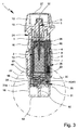
図3は、完全に閉じたネブライザハウジング24、従って、閉じたハウジング部分18と共に、概略断面(長手方向断面)で非引張状態の本発明による容器3及び表示デバイス25を有するネブライザ1を示し、提案する表示デバイス25を含む容器3は、ネブライザ1及び/又はハウジング24に挿入されるか又はその内部に受け入れられる。
FIG. 3 shows a
図4は、図3の丸で囲まれた部分の拡大部分断面を示している。図5は、図3のネブライザ1の断面の斜視図である。図6は、図5の丸で囲まれた部分の部分拡大図を示している。
FIG. 4 shows an enlarged partial cross section of a portion surrounded by a circle in FIG. FIG. 5 is a perspective view of a cross section of the
ネブライザ1は、好ましくは、軸線方向及び/又は主小出し方向及び/又は引張及び小出し中に容器3の行程移動に対応する細長い形態又は軸線を有する。
The
図示の非引張状態において、ネブライザ1又はそのマウスピース13は、好ましくは、マウスピースカバー27によって閉じられる。マウスピースカバー27は、好ましくは、ピボット回転可能であり、ネブライザ1を使用するためのマウスピース13の開口を可能にする。
In the non-tension state shown, the
好ましくは、表示デバイス25は、容器3に直接に及び/又は解除不能に取りつけられるか又はそれに接続される。特に、表示デバイス25は、それぞれの容器3に関連付けられる。ネブライザ1の容器3が取り替えられる場合に、表示デバイス25も必ず又は能動的に取り替えられる。
Preferably, the
好ましくは、表示デバイス25は、容器3の底部又は容器ベース21に、及び/又は容器3の出口又はヘッド28の反対側に固定的に配置される。
Preferably, the
好ましい実施形態において、表示デバイス25は、好ましくは、容器3の外側ケース又は好ましくは剛性のハウジング29に直接に接続されるか又はそこに当接される。
In a preferred embodiment, the
好ましくは、表示デバイス25及び容器3は、形状適合により及び/又はスナップ式に接続される。
Preferably, the
特に、表示デバイス25は、容器3の(下側又は底部)縁部30及び/又はいずれかの他の突起などにわたって取り囲み及び/又は把持する。本発明の実施形態において、縁部30は、それが、容器3/容器ハウジング29の側壁の本質的に円筒形の外形にわたって半径方向に突出するように僅かに広い直径である。
In particular, the
表示デバイス25の直径は、好ましくは、容器3又はその縁部30の直径に少なくとも本質的に等しいか又は僅かにこれよりも大きい。
The diameter of the
縁部30は、好ましくは、容器3又は容器ハウジング29の側壁と底部又はベース21との間に形成される。好ましくは、縁部30は、フランジをつけるか、境界を付けるか、曲げるか、又は圧着することによって又はいずれかの他の適切な材料変形工程によって形成される。
The
表示デバイス25は、ハウジング31を含み、及び/又は好ましくは少なくとも本質的に円筒形形態を有する。
The
表示デバイス25又はそのハウジング31は、好ましくは、少なくとも本質的に平坦及び/又は軸線方向側で容器3又はそのベース21又はハウジング29に取りつけられる。
The
表示デバイス25又はそのハウジング31は、好ましくは、表示デバイス25を容器3と接続するための保持又は把持セクション32を含む。好ましくは、把持セクション32は、縁部30を取り囲み、及び/又は縁部30の周り又はそれにわたって把持する。
The
本実施形態において、把持セクション32は、好ましくは、環状であり、及び/又は縁部30又は容器3の円周にわたって配置された位置で縁部31にわたって把持する。
In this embodiment, the gripping
好ましくは、表示デバイス25及び容器3は、互いにスナップ式又はクリック接続によって接続される。好ましくは、容器3及び表示デバイス25は、一方の部品を他方の上に軸線方向にスナップ結合することによって互いに接続される。
Preferably, the
好ましくは、把持セクション32は、容器3がその縁部30と共に軸線方向に入ることができるように半径方向に十分に弾性である。本発明の実施形態において、把持セクション32は、好ましくは、それぞれ傾斜した挿入面を含み、環状把持セクション32の中に又は周方向に配置された把持セクション32の間への縁部30の挿入を容易にする。
Preferably, the gripping
他の構成的ソリューションが容器3又はそのハウジング29を表示デバイス25又はそのハウジング31と接続するために実施可能であり、又はその逆も可能であることに注意しなければならない。特に、2つの部品は、これ加えて又はこれに代えて、溶接、ろうつけ、接着、ねじ込み、クランピング、又はホットプレスなどによって互いに接続することができる。
It should be noted that other constructive solutions can be implemented to connect the
図7は、本発明の好ましい実施形態による表示デバイス25を概略分解組立図に示している。
FIG. 7 shows a
表示器、又はそのハウジング31は、好ましくは、上側部分33及び下側部分34を含む。
The indicator, or its
好ましくは、上側部分33は、把持セクション32を保持又は形成する。
Preferably, the
表示デバイス25は、好ましくは、表示要素35及び関連の起動要素36、及び/又は表示要素35を回転送り(インデクシング、indexing)するために又は表示要素35の回転送りを引き起こすための伝達部40又は歯車41を含む。
The
表示デバイス25は、それぞれの又は関連の容器3を用いて実施されたか又は依然として実施可能な使用回数を計数し、及び/又はそれを示すためのものである。好ましくは、表示要素35は、それぞれの容器3を用いて既に実施されたか又は依然として実施可能な使用回数を少なくとも略示するために、1又は2以上の記号、数字、着色、又は陰影区域などのいずれかのマーキング37を含む。本発明の実施形態において、表示要素35は、好ましくは、回転可能であり、及び/又は少なくとも1つのマーキング37を有する周方向壁又は外面を含む。
The
表示器ハウジング31は、好ましくは、窓31aを含み、特に関連付けられたマーキング37を通じて周方向壁において、好ましくは、特に透明なハウジング部分18を通じてユーザ又は患者に見える。
The
起動要素36は、好ましくは、起動アーム38を含み、これは、次に、好ましくは、表示要素35の直接又は間接起動又は回転送りのための自由又は起動端39を含む。回転送りは、表示要素35が一定分だけ又は段階的に前方に移動されることを意味する。
The
好ましいのは、起動要素36又はそのアーム38が伝達部40を通じて表示要素35を起動又は駆動するような間接起動又は駆動である。本発明の実施形態において、伝達部40は、減速をもたらし、及び/又はウォームデバイスとして実現される。
Preference is given to indirect activation or actuation, in which the
表示デバイス25又は伝達部40は、好ましくは、歯車41及び/又はウォーム42を含む。最も好ましくは、ウォーム42は、歯車41が、ウォーム歯車を形成し、好ましくは、ウォーム42の少なくとも1つの回旋を形成する半径方向に突出した歯43を含むように、歯車41によって直接に形成される(図8及び9に示す装着された表示デバイス25の水平又は軸線方向断面と比較されたい)。
The
歯車41は、好ましくは、心棒、特に、本発明の実施形態で実現するような軸線方向に両側に突出することができる1又は2以上の心棒セクション44を含む。
The
起動要素36は、好ましくは、起動要素36の移動方向に垂直な軸線の周りの歯車41の回転を引き起こし、軸線は、好ましくは、起動要素36の移動によって与えられる平面と同一又はそれと平行の水平面に配置される。
The
歯車41は、好ましくは、ハウジング31又は下側ハウジング部分34により、好ましくは、下側部分34の2つの軸受セクション45によって回転可能に保持される。好ましくは、軸受セクション45は、心棒セクション44を回転可能に保持するための凹部を含む。しかし、他の構成的ソリューションも同様に可能である。
The
ハウジング31又は下側部分34は、好ましくは、表示要素35をそれが回転することができるように担持する。好ましい実施形態において、下側部分34は、好ましくは、半径方向両側に配置され、表示要素35を回転可能に担持するために軸線方向に突出した2つの軸受部分46を含む。起動要素35及び/又は伝達部40は、好ましくは、少なくとも本質的には軸受部分46の間に配置される。
The
表示デバイス25は、特に、起動要素36を好ましい方向に付勢するために及び/又は表示要素35を駆動するために、好ましくは、起動バネ47を含む。
The
図8は、起動状態の装着された表示デバイス25を水平又は軸線方向断面に示し、ここで起動要素36は、横向きに、つまり図3〜6に示す第1の位置から始まって図8に示す第2の位置の中に左側に向けて移動するか又は押されている。
FIG. 8 shows the mounted
図9は、ロック状態の表示デバイス25を図8と類似の断面に示し、ここで起動要素36は、ロックした第3の位置にある。
FIG. 9 shows the
表示要素35(図8及び9には示さず)の突起60が軸線方向に延びることは図8及び9から分かり、少なくとも1つの突起60は、常に、ウォームドライブが歯車41と表示要素35の間に形成されるようにウォーム42に捕捉される。従って、歯車41のあらゆる回転は、表示要素35の減速回転に変換される。更に、歯車41と表示要素35の間、より正確には少なくとも1つの突起60とウォーム42の間で恒久的係合が保証される。しかし、他の構成的ソリューション又は歯車41と表示要素35の間の連結が実施可能である。
It can be seen from FIGS. 8 and 9 that the
図10は、初期の第1の位置及び状態の装着された表示デバイス25を斜視断面に示している。図11は、類似の斜視断面であるが、解除された起動要素36、すなわち、ロック状態が到達される直前の表示デバイス25を示している。
FIG. 10 shows a perspective view of the mounted
好ましくは、伝達部40又は歯車41は、表示要素35の又はいずれかの他の伝達部構成要素の少なくとも1つの係合要素、特に内向きに又は軸線方向に突出する突起60が常にウォーム42において係合するように、少なくとも1つの回旋で、好ましくは、約1.5又はそれよりも多くの回旋でウォーム(螺旋状溝)42を形成する。従って、その好ましくは横断軸線の周りの歯車41の回転は、その好ましくは長手方向に向けられた回転軸の周りに表示要素35の回転をもたらす。しかし、他の構成的ソリューションも同様に可能である。
Preferably, the
好ましくは、歯43は、突起が歯43の間でウォーム42の回旋内に確実に案内され、起動部分39が望ましい方式で歯車41を起動又は回転させるように、ウォーム42の中に係合する突起60と歯車41の間で半径方向に依然として移動することができるように比較的長く及び/又は半径方向に十分に延びる。この目的のために、起動部分39は、それぞれの突出部60の下を移動することができるように、歯43の間でそれぞれ深い切欠き部の中に係合することができる。
Preferably, the
表示デバイス25は、好ましくは、穿孔部分48を含む(図3〜6と比較されたい)。
The
穿孔部分48は、表示デバイス25又はそのハウジング31内に配置される。
The perforated
穿孔部分48は、好ましくは、軸線方向に移動可能である。
The piercing
穿孔部分48は、特に、通気孔23を覆うホイル50を破断又は穿孔することにより、それが容器3に向けて突出することができ及び/又は容器3の曝気開口部、好ましくは、通気孔23を開くことができるように移動可能であることが好ましい。
The perforated
本発明の実施形態において、穿孔要素48は、好ましくは、容器ベース21を覆うホイル50を開放又は穿孔することができる開放端又は先端49、特に、容器3又はそのベース21に形成された窪み51を含む。好ましくは、窪み51は、通気孔23を形成する突破口を含む。しかし、他の構成的ソリューションも同様に可能である。
In an embodiment of the present invention, the piercing
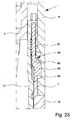
図12は、部分引張後の中間状態のネブライザ1の下側部分を図4に類似の部分拡大図に示している。表示デバイス25は、図8に示すように起動状態にある(第2の位置)。
FIG. 12 shows the lower part of the
ネブライザ1又はハウジング部分18は、好ましくは、ネブライザ1を使用する時に表示デバイス25を駆動又は起動するために、特に、ネブライザ1のあらゆる引張及び/又は容器3のあらゆる(軸線方向又は行程状)移動に応答して表示デバイス25を起動するための駆動部分52を含む。
The
好ましくは、駆動部分52は、ハウジング部分18に、特に、ハウジング部分18の軸線方向端面又は底部53上に配置又は形成される。
Preferably, the
好ましくは、駆動部分52は、中心に配置され、及び/又は軸線方向に延びる。
Preferably, the
好ましくは、駆動部分52は、少なくとも実質的に円筒形及び/又はピン状又はボルト状である。
Preferably, the
好ましくは、駆動部分52は、ハウジング部分18によって保持され、及び/又はハウジング部分18によって一体的に形成される。
Preferably, drive
好ましい実施形態において、容器3の移動、従って、引張(図面では下向き移動)中及び/又は加圧及び小出し(図面では上方移動)中の表示デバイス25の移動、及び/又はそれぞれ非引張状態及び引張状態のそれぞれの端部位置の一方又は両方の移動は、表示デバイス25を起動するために、すなわち、計数するために使用することができる。
In a preferred embodiment, the movement of the
好ましくは、ネブライザ1内の容器3及び/又は表示デバイス25の相対移動、より好ましくは、小出し中の移動は、表示デバイス25を起動又はトリガ及び/又は計数するために使用される。
Preferably, the relative movement of the
ネブライザ1を引張し、及び/又は表示デバイス25を下向きに移動する時に、駆動部分25は、表示デバイス25又はそのハウジング31の挿入開口部54を通じて、特に軸線方向に入り、又は係合する。
When pulling the
好ましくは、駆動部分52及び挿入開口部54は、中心に配置され、及び/又は軸線方向に位置合わせされる。
Preferably, the
好ましい実施形態において、駆動部分52は、起動要素36を起動させ、すなわち、図3〜6に示す初期の第1の位置から図9に示す起動された第2の位置に起動要素36を移動する。
In a preferred embodiment, the
好ましくは、起動バネ47は、起動要素36を第1の位置へと付勢する。
Preferably, the
本発明の実施形態において、起動要素36は、表示要素35を回転送りするために、特に、それぞれ表示要素35を駆動するように一方向に歯車41を段階的に回転させるために第1及び第2の位置の間で前後に移動可能である。歯車41のいずれかの回転が表示要素35の減少回転に変換される時に、第1から第2の位置へ又はその逆の起動要素36の全ての移動は、従って、表示要素35の移動をもたらす。
In an embodiment of the present invention, the
本発明の実施形態において、起動要素36は、容器3又はネブライザ1の長手方向又は小出し方向に及び/又は容器3及び/又は表示デバイス25の行程移動に対して横断方向に、好ましくは、垂直に移動可能である。
In an embodiment of the invention, the
好ましくは、起動要素36は、より中心の第1の位置から第2の位置まで半径方向外向きに、特に、反対方向に起動要素36を付勢する関連の好ましくは螺旋状起動バネ47の力に対して移動する。
Preferably, the
第2の位置で、起動要素36は、図8及び12に示すように、歯車41との係合から出てその起動アーム38又は起動部分39と共に移動している。
In the second position, the
図13は、完全引張状態を図12と類似の拡大断面に示している。 FIG. 13 shows a fully tensioned state in an enlarged cross section similar to FIG.
(完全)引張状態において、容器3、より正確には曝気開口部又は通気孔23は、少なくともネブライザ1が初めて容器3を用いて引張された時に開かれる。
In the (fully) tensioned state, the
好ましくは、曝気のための容器3又は通気孔23の開放は、特にホイル50の穿孔又は破断によって実現される。
Preferably, the opening of the
開口又は穿孔は、駆動部分52によって直接に達成することができる。これに代えて、開口又は穿孔は、駆動部分52とは独立に、例えば、図2に示す実施形態と類似の穿孔要素22を有する曝気バネ20を使用して達成することができる。これに代えて、本発明の実施形態におけるように、開口又は穿孔は、好ましくは、駆動部分52によって起動されることが好ましい穿孔部分48を通じて間接的に達成することができる。
Opening or drilling can be achieved directly by the
好ましくは、穿孔部分48は、個別の部品として形成され、及び/又は表示デバイス25によって提供され、及び/又は表示デバイス25内に配置される。
Preferably, the perforated
好ましい実施形態において、穿孔部分48は、図10及び11に概略的に示すように、表示デバイス25、ハウジング31、上側部分32、及び/又は表示要素35の支持構造55によって軸線方向に移動可能に保持される。
In a preferred embodiment, the perforated
好ましくは、穿孔部分48及び/又は支持構造55は、表示デバイス25の更に別の部品、例えば、表示要素35又は表示器ハウジング31、特に表示器ハウジング31の上側部分33との一体構成である。
Preferably, the perforated
好ましくは、穿孔部分48、支持構造55、及び表示デバイス25の更に別の部品は、射出成形工程でプラスチックで作られる。
Preferably, the perforated
好ましくは、支持構造55は、穿孔部分48を軸線方向に移動可能に保持するための可撓性アーム又はリブを含む。
Preferably, the
これに代えて、穿孔部分48は、個別の軸線方向に移動可能な部品として構成することができ、これは、穿孔先端49が容器3から非引張状態で後退するように、任意的に容器3から離れて長手方向又は軸線方向に付勢するバネである。
Alternatively, the piercing
穿孔部分48又はその先端49は、好ましくは、表示デバイス25又はそのハウジング31内に受け入れられるが、起動状態において外向きに突出することができることに注意しなければならない。
It should be noted that the perforated
開口又は穿孔は、ネブライザ1を引張する度に、すなわち、容器3が引張状態でその端部位置が到達される度に繰り返すことができる。
The opening or perforation can be repeated each time the
穿孔部分48は、図3〜6に示すその後退又は初期位置に、特に、好ましくは、一体的に形成された付勢アーム又はバネなどにより、好ましくは、支持構造55によって付勢することができる。
The perforated
穿孔部分48は、軸線方向のあらゆる公差を補償するために可撓性アーム56のような補償部分を含むことができる。そのような公差は、特に、製造中の変動、特に容器3及び/又は他の構成要素の長さの変動、表示デバイス25と容器3の接続の変動、表示デバイス25又はそのハウジング31の長さの変動、ホルダ6内の容器3の軸線方向位置の変動などにより起こる可能性がある。従って、駆動部分52の自由端と穿孔部分48のカウンター面との間に様々な距離が得られる場合がある。この構成は、駆動部分52及び穿孔部分48が、望ましい穿孔を保証するようにあらゆる場合に協働するようなものである。
The perforated
補償部分は、容器3及び/又はネブライザ1のいずれかの他の構成要素のあらゆる損傷を回避するために、ここではアーム56の半径方向屈曲により、予め決められた軸線方向力を超える時に軸線方向圧縮を可能にする。従って、好ましい実施形態において、駆動部分52は、最初に穿孔部分48を容器ベース21に向けて穿孔位置の中に移動し、駆動部分52の更なる軸線方向移動は、補償部分により、好ましくは、半径方向外向きに広がっている可撓性アーム56によって補償され、穿孔部分48の中心凹部(穿孔先端49の反対側)に入るために駆動部分52の先端に取って代わられる。
The compensating part is provided with a radial bend of the
穿孔部分48は、たとえ穿孔部分48がホイル50又は穿孔位置に詰まり又は留まる場合でも曝気又は通気を阻止しないことを保証するために、好ましくは、少なくとも1つの軸線方向チャネル、特に先端49の円周回りに周方向に配置された1又は2以上の軸線方向に延びる溝57を含む。
The perforated
図14は、図4、12、及び13と同様の拡大図で、加圧又は小出し工程の中間状態、すなわち、容器3が再度部分的に上方に移動している時を示している。この状態において、駆動部分52は、起動要素36が起動バネ47の力によりその初期又は第1の位置に戻り始めるように、部分的に表示デバイス25から又は挿入開口部54を通じて引き戻されている。最後に、駆動部分52の十分な引き戻しの後に、起動要素36は、戻り移動が完了した時に図3〜6に示す第1の位置に戻る。
FIG. 14 is an enlarged view similar to FIGS. 4, 12, and 13, showing an intermediate state of the pressurizing or dispensing step, that is, when the
容器3及び/又は起動要素36の戻り移動は、好ましくは、表示デバイス25又は歯車41を起動させ、及び/又は検出又は計数される。特に、起動要素36又はそのアーム38又は起動部分39は、戻り移動又は第2から第1の位置への移動を伝達部40に伝達する。特に、この移動は、歯車41の段階的回転を引き起こす。
The return movement of the
従って、本発明の実施形態において、小出し中のネブライザ1内の容器3及び/又は表示デバイス25の移動は、好ましくは、表示デバイス25を起動又はトリガするために及び/又は計数するために使用される。
Thus, in embodiments of the present invention, movement of the
本発明の実施形態において、起動アーム38又はその部分39は、戻り移動中に歯車41の1つの歯43に対して当接し、従って、更に1段階の戻り移動により、時計回り方向に図面内で歯車41を回転させる。
In an embodiment of the invention, the
好ましくは、表示デバイス25は、伝達部40又は歯車41のあらゆる反回転を防止するラチェット58を含む。本発明の実施形態において、ラチェット58は、ハウジング31、特に下側ハウジング部分34から延び、及び/又は歯車41又はその歯43と噛み合うか又はその中に係合する可撓性アームによって形成される。
Preferably,
端部位置において、すなわち、非引張状態において、駆動部分52は、好ましくは、図3〜6に示すように、表示デバイス25、表示器ハウジング31、及び/又は挿入開口部54から更に又は完全に後退する。
In the end position, i.e. in the non-tension state, the
伝達部40又は歯車41は、起動、特に、起動要素36又はそのアーム38/起動部分39の(後方)移動を表示要素35の回転送りに変換する。伝達部40又は歯車41の伝達比又は伝達関数は、減速又は非線形駆動又は回転送りを達成するように設計又は構成することができる。本発明の実施形態において、伝達部40又は歯車41は、好ましくは、望ましい減速を達成するためにウォームドライブを形成する。
The
特に第1の位置から第2の位置への起動要素36の移動は、起動アーム38又はその起動部分39が歯車41との係合から出て移動するという結果をもたらし、特に、次の歯43の上に引くことができる。それによって、アーム38は、外に屈曲される。反対方向のその後の移動、すなわち、戻り移動又は第2から第1の位置への移動は、起動アーム38又はその起動部分39が次の歯41と接触し、アーム38の少なくとも本質的線形移動、より正確には、好ましくは、起動要素36の線形移動を歯車41の回転へと、より正確には、好ましくは、1つの歯43による歯車41の回転送りに伝達することができるという結果をもたらす。
In particular, movement of the
好ましくは、歯43は、非対称であり、すなわち、起動アーム38の前後移動及び係合によって1回転方向の段階的起動及び移動を容易にし、及び/又は保証するために、一方側及び他方側に別々に傾斜した肩部を含む。
Preferably, the
好ましくは、起動要素36は、線形に移動可能であり、及び/又は摺動キャリッジを形成する。
Preferably, the
好ましくは、起動要素36は、ハウジング31、特にハウジング31の下側部分34によって移動可能に支持され及び/又は保持される。しかし、他の構成的ソリューションも同様に可能である。
Preferably, the
起動バネ47は、好ましくは、一方でハウジング31又は下側部分34と他方で起動要素36との間で作用する。
The
本発明の実施形態において、バネ47は、好ましくは、それが少なくとも部分的に挿入開口部54を閉鎖又は阻止するように、第1の位置で既に圧縮され及び/又は付勢され、及び/又は起動要素36を付勢する。
In an embodiment of the present invention, the
好ましくは、起動要素36は、第1の位置の挿入開口部32の中又はその上を保護するその部分に傾斜滑走面59を含む。この面59は、駆動部分52の挿入、すなわち、その軸線方向移動又は当接が、起動要素36の横断方向又は半径方向移動に変換されるように傾斜している。
Preferably, the
これに代えて又はこれに加えて、そのような面59はまた、斜面を使用して横断方向又は半径方向移動への軸線方向移動の望ましい変換を達成するように駆動部分52に形成することができる。
Alternatively or additionally, such a
従って、伝達部40又は歯車41の起動又は回転は、好ましくは、起動バネ47の力又はいずれかの他の圧力又はエネルギ貯蔵又はバネ手段によって達成することができる。これは、表示デバイス25又はその表示要素35を駆動するのに追加の力を必要としないという利点をもたらす。その結果、加圧及び小出し工程を妨げない。
Thus, activation or rotation of the
更に、伝達部40/歯車41の計数又は起動のトリガは、好ましくは、加圧又は小出し工程又は移動により、すなわち、流体2の実際の小出し中、すなわち、一般的に実際の使用又は吸入中に達成される。
Furthermore, the triggering of the counting or activation of the
起動バネ47は、好ましくは、挿入開口部54の閉鎖に向けて起動要素36を付勢する。
The
通常、起動要素36の移動は、ロック状態に到達される前にそれが挿入開口部54を完全に閉鎖しないように制限される。この制限は、本発明の実施形態において、好ましくは、制御部63が特に第1の位置で起動要素36の戻り移動を制限するように当接する制御手段又は部分62を通じて実現される。
Normally, movement of the
当接は、特に図10に示されている。しかし、他の構成的ソリューションも同様に可能である。 The abutment is shown in particular in FIG. However, other constructive solutions are possible as well.
容器3とのネブライザ1の使用回数が到達されるか又は表示デバイス25によって検出又は表示される時の予め決められた使用回数が超過された後に、ロック状態に入り、ネブライザ1は、現在の容器3との更なる使用に対してロックされることになり、及び/又は容器3は、ネブライザ1との更なる使用に対してロックされることになる。
After the number of uses of the
特に、表示デバイス25は、図4及び12〜14と類似の部品を示す図15の概略的拡大で概略的に示すように、容器3の更なる使用を阻止し、及び/又はロック状態で挿入開口部54を閉鎖又は阻止する阻止部分61を含む。この図示の状態において、容器3は、その非引張位置に戻っており、駆動部分52は、表示デバイス25から後退している。最後の小出し又は加圧工程中に、表示デバイス25は、表示要素35を更に1段階移動し、予め決められた使用回数が到達されるか又は超過されたこと、従って、ロック状態に入るべきであることを検出又は表示している。
In particular, the
本発明の実施形態において、表示要素35は、好ましくは、更なる使用に対してネブライザ1又は現在の容器3のロッキングをもたらすロック状態の検出に対して起動要素36を解除する制御部分62を含む。
In an embodiment of the present invention, the
好ましくは、制御部分62は、阻止位置への阻止部分61の移動を可能にするか又は開始する切欠き部又は凹部を含む。好ましくは、阻止部分61は、阻止位置で、すなわち、ロック状態で挿入開口部54を阻止又は閉じる。好ましくは、制御部分62は、回転可能な表示要素35の内側の壁又は隆起部である。
Preferably,
好ましくは、阻止部分61は、表示デバイス25又はそのハウジング31に一体化される。
Preferably, the blocking
阻止部分61は、好ましくは、容器又はネブライザ1の長手方向又は小出し方向に対して及び/又は容器3の行程移動の方向に対して横断方向又は垂直に移動可能である。
The blocking
好ましくは、阻止部分61は、駆動部分52の起動又は挿入移動を、特に表示デバイス25及び/又は駆動部分52の(十分な)挿入に対して阻止する。
Preferably, the blocking
好ましくは、阻止部分61は、直線的に移動可能であり、及び/又は摺動キャリッジによって形成される。しかし、他の構成的ソリューションも同様に可能である。
Preferably, the blocking
好ましくは、阻止部分61は、本発明の実施形態では、好ましくは、起動バネ47又はいずれかの他の適切な付勢手段によってその阻止位置へと付勢される。
Preferably, the blocking
好ましくは、阻止部分61は、流体2の最後の投薬量が小出しされた後かつロック状態に入るか又は検出された時に、表示デバイス25の挿入開口部54を閉鎖又は阻止する。この検出は、好ましくは、阻止部分61又は制御部63のようなあらゆる関連の構成要素を最も好ましくはバネ力により、特に図11に概略的に示すような起動バネ47などの力により、制御部分62を通じてロック状態にすることができるということで達成される。
Preferably, the blocking
好ましくは、阻止部分61は、起動要素36と接続されるか又はそれによって形成され、又はその逆も可能である。最も好ましくは、阻止部分61は、起動要素36の壁又は側面、好ましくは、平坦側面を形成する。しかし、他の構成的ソリューションも同様に可能である。
Preferably, the blocking
本発明の実施形態において、起動要素36は、ロック状態で第1の位置から第3の位置まで、すなわち、好ましくは、移動とは反対方向に第2の位置まで移動することができる。
In an embodiment of the present invention, the
本発明の実施形態において、起動要素36は、好ましくは、第3の位置(阻止位置)で完全に挿入開口部54を閉じることができる。
In an embodiment of the present invention, the
言い換えると、阻止部分61の阻止位置は、好ましくは、起動要素36の第3の位置に対応する。
In other words, the blocking position of the blocking
ロック状態又は第3の位置では、起動要素36は、起動部分39が、図15に示すように歯車41の回転方向に以前の歯43を通過するように、起動アーム38又はその部分39と共に起動方向に更に移動している。
In the locked state or the third position, the
好ましくは、起動要素36は、ロック状態又は第3の位置(阻止位置)で容器3の更なる使用を阻止するように構成される。
Preferably, the
好ましくは、起動要素36は、表示要素35を回転送りするために第1及び第2の位置の間で前後に移動可能であり、ロック状態で容器3の更なる使用を阻止するように第3の位置まで移動可能である。
Preferably, the
上記及び以下の説明、並びに特徴は、好ましくは、図19及び20に関連して後で説明する修正実施形態にも同様に又はこれに加えて適用される。 The above and below description and features preferably apply equally or additionally to the modified embodiments described below in connection with FIGS. 19 and 20.
特に、閉じた表示デバイス25又は阻止部分61は、特に、容器3が、上述のようなかつ通常の使用を防止するように通常の又は更なる使用の必要に応じて行程様式でネブライザ1の閉じたハウジングの内側で移動することができないという結果をもたらす。
In particular, the
特に、表示デバイス25又は挿入開口部54のロッキングは、ネブライザ1及びハウジング部分18が、ネブライザ1がもう一度引張された時又はそれが部分的に引張された時に少なくとも部分的に開かれるという結果をもたらす。図16は、ネブライザ1のこの状態(部分的に開いたハウジング部分18を有する部分的に引張されたネブライザ1)を概略的な長手方向断面に示している。引張工程中に、容器3は、表示デバイス25と共に下向きに移動している。非引張状態(容器3の上側位置)から始まって、表示デバイス25は、更なる通常の下向き移動が可能ではないように、通常は表示デバイス25、ここでは駆動部分52を起動する部材に対してその阻止部分61/起動要素36によって間もなく当接する。
In particular, locking of the
特に、阻止部分61は、好ましくは、駆動部分52が表示デバイス25に挿入するのを防止し、又はロック状態でその挿入を制限することにより、ロック状態でネブライザ1の容器3の軸線方向可動性を制限する。ネブライザ1が引張された時に加わる力により、及び容器3の移動において生じた軸線方向力により、ハウジング部分18は、ロック状態で軸線方向の更なる引張移動中に容器3及び表示デバイス25と共に、外側に又はネブライザ1、内側部分17、又は上側部分16に対して移動することになる。
In particular, the blocking
容器3、表示デバイス25、及びハウジング部分18の上記共通下向き移動は、ネブライザ1においてハウジング部分18のそれぞれ構成された締結により可能である。特に、保持力は、それを容器3の下向き移動によって打ち勝つことができるように選択又は設定される。
Said common downward movement of the
本発明の実施形態において、保持要素19は、ハウジング部分18のそれぞれの保持凹部65において保持ノーズ64と係合し、その逆も可能である。従って、実質的に刻み目又は窪みを実現することができる。しかし、一方でノーズ64及び他方で凹部65の少なくとも本質的に半径方向に延びる当接肩部は、保持要素19が半径方向に屈曲して保持係合に打ち勝つように、引張工程の軸線方向力がノーズ64の係合によって凹部65の中に提供される保持力に打ち勝つことができるように半径方向平面に対して好ましくは約1°〜5°だけ僅かに傾斜している。その結果、ハウジング部分18は、下向きにも移動し、従って、少なくとも部分的にネブライザ1から押されるか又は上側ハウジング部分16から分離され、及び/又は内側部分17から押される。
In an embodiment of the invention, the retaining
ハウジング部分18のこの押すか又は軸線方向の変位又はネブライザ1のいずれかの他の開放は、好ましくは、ロッキングデバイス26を使用して更なる使用に対してネブライザ1をロックするという結果をもたらす。従って、表示デバイス25又はその阻止部分61は、ロック状態でのネブライザ1の望ましいロッキングをネブライザ1の開放を通じて間接的に達成する。
This pushing or axial displacement of the
好ましい実施形態において、ロッキングデバイス26は、ロック状態でネブライザ1の引張を阻止する。
In a preferred embodiment, the locking
好ましくは、ロッキングデバイス26は、移動可能なロッキング要素66及び関連のロッキングバネ67を含む。ロッキング要素66は、好ましくは、ロック位置とアンロック位置の間で軸線方向に移動可能である。ロッキング要素66は、好ましくは、ロッキング位置/ロッキングバネ67によってロックされた位置の中に付勢される。
Preferably, the locking
ロック位置では、ロッキング要素66は、好ましくは、図16に示すその下側軸線方向位置にある。図17は、図16の丸で囲まれた区域の拡大を示している。
In the locked position, the locking
ロック位置では、ロッキング要素66は、外側部分16に対して内側部分17の回転を阻止し、従って、ネブライザ1の(更なる)引張を阻止する。これは、好ましくは、ロッキング要素66が、上述の相対回転を阻止するように上側部分16に形成されたそれぞれのポケット68の中に(単に)軸線方向に移動又は係合するということで本発明の実施形態において達成される。特に、ロッキング要素66は、あらゆる更なる回転及び/又は戻り回転を防止するように、それぞれの凹部又はポケット68の中に係合部分69と係合する。しかし、他の構成的ソリューションも同様に可能である。
In the locked position, the locking
好ましくは、係合部分69は、半径方向に突出し、及び/又は少なくとも本質的にリブ状である。
Preferably, the
本発明の実施形態において、ロッキング要素66は、好ましくは、開かれるか又は切欠かれた上側ハウジング部分16を有する図16の丸で囲まれた部分の領域内のネブライザ1の概略側面図である図21に示すように、複数の又は3つの係合部分69を含む。しかし、図21は、そのアンロック又は上側位置にロッキング要素66を示している。
In an embodiment of the invention, the locking
係合部分69は、好ましくは互いに平行に及び/又は軸線方向又は起動方向に延びる。
The
係合部分69は、好ましくはリブ状であり、及び/又は半径方向及び/又は外向きに突出する。
The
係合部分69と共にロッキング要素66は、好ましくは1ピースで及び/又は一体化又は剛性部品として形成され、及び/又は好ましくはプラスチックで作られる。
The locking
図22は、ロック状態又は位置でのロッキングデバイス26又はそのロッキング要素66の係合、すなわち、ネブライザ1の特に上側又は外側ハウジング部分16に対する内側部分17及び/又は下側ハウジング部分18の回転阻止を概略半径方向断面に示している。
FIG. 22 shows the engagement of the
特に、ロック状態において、係合部分69は、ネブライザ1のハウジング部分16に又はその近く(その内側)に形成された別々の又は対応するポケット68の中に係合するか又は突出する。しかし、他の構成的ソリューションも同様に可能である。
In particular, in the locked state, the
ロッキング要素66は、ロッキング要素66が、好ましくは、軸線方向にのみ移動可能であるように、図22に概略的に示すように、好ましくは、内側部分17により、及び/又はそれぞれの溝75において、及び/又は好ましくはリブ状突起76などによって案内される。しかし、他の構成的ソリューションも同様に可能である。
The locking
ロッキングデバイス26、特にロッキング要素66及びロッキングバネ67は、好ましくは、内側部分17に配置され及び/又は内側部分17によって支持され及び/又は内側部分17と上側部分16の間を延びる。
The locking
ネブライザ1、内側部分17、又はロッキングデバイス26は、好ましくは、ユーザ又は患者によるロッキングデバイス26又はロッキング要素66のあらゆる望ましくない操作を防止又は少なくとも複雑にするために、内側部分17の下側部分17bの少なくとも周囲でロッキングデバイス26を覆うカバー70を含む。
The
好ましくは、ロッキングデバイス26又はロッキング要素66は、完全な引張状態又は位置が到達される前に、すなわち、好ましくは中間位置で、最も好ましくは、上側ハウジング部分16に対して下側ハウジング部分18を回転させることによってネブライザ1を引張するのに必要な全回転角度の後半で、相対回転又は更なる回転をロックしている。
Preferably, the locking
この中間阻止は、完全な引張に到達するのが不可能であり、従って、相対回転をホルダ6の軸線方向行程に変換する歯車又は伝達部は、実際に中間位置にホルダ6を保持し、上側非引張位置へのいかなる軸線方向戻り移動を許さないので、ネブライザ1を完全に起動することは好ましくは可能ではないという利点を有する。
This intermediate blocking makes it impossible to reach full tension, so that the gears or transmissions that convert the relative rotation into the axial travel of the
しかし、完全引張状態を達成した後の更なる引張に対して、ロッキングデバイス26がネブライザ1をロックすることも可能である。
However, it is also possible that the locking
これに代えて又はこれに加えて、ロッキングデバイス26又はそのロッキング要素66が、特に、阻止要素8のあらゆる押し下げをロックし、従って、解除を阻止することにより、バネ7又はホルダ6の解除をロックして流体2を小出しすることも可能である。しかし、他の構成的ソリューションも同様に可能である。
Alternatively or additionally, the locking
一般的に、ロッキングデバイス26又はそのロッキング要素66は、更に、ネブライザ1の起動を阻止し、又は1回分の流体2の噴霧のトリガを阻止し、又は阻止要素8又はネブライザ1の他の起動ボタンなどの押し下げを阻止するように適応させることができる。これは、ロック状態でネブライザ1の更なる使用を阻止する追加の手段を形成することができる。
In general, the locking
好ましくは、ネブライザ1又は上側部分16は、1又は2以上の金属インサート又は強化要素によって強化することができ、それらは、リング状とすることができ、及び/又は周方向に延びることができ、及び/又はポケット68に隣接して又はその周りに及び/又は上側部分16の下端又は自由端に隣接して配置することができる。
Preferably, the
図18は、図16と類似の概略断面であるが、ロッキングデバイス26がアンロック位置に、すなわち、ロッキング要素66が上側位置にあるネブライザ1を示している。ロッキングデバイス26又はロッキング要素66は、この位置にもたらされ、又は好ましくは単にネブライザ1を閉じることにより、特に、完全に取り付けられた又は閉じた位置にあるハウジング部分18によってアンロックされる。
FIG. 18 is a schematic cross-section similar to FIG. 16, but showing the
図示の実施形態において、ハウジング部分18は、図18に示すように、ロッキングデバイス66の中に及び/又はカバー70の中に延び、及び/又はロッキング要素66に軸線方向に当接し、及び/又はそれをそのアンロック位置(上側位置)に押し込む好ましくは指状及び/又は軸線方向に延びるアクチュエータ71を含む。従って、完全に閉じたネブライザ1又はハウジング部分18だけが、ロッキングデバイス26をアンロックし、従って、ネブライザ1をアンロックする。
In the illustrated embodiment, the
アクチュエータ71は、好ましくは、いずれの操作も可能ではなく又は少なくとも複雑であるようにハウジング部分18内に配置される。
The
ネブライザ1がロック状態にある時に、好ましくは、ネブライザ1又はそのハウジング部分18が最終の引張工程によって部分的に開いている時に、容器3及び表示デバイス25を有するネブライザ1のそのロック状態におけるあらゆる更なる使用は、可能ではない。ロッキングデバイス26は、好ましくは、自動でロックする。好ましくは、ロッキングバネ67は、ロッキング要素66をロック位置内に付勢し、従って、ネブライザ1の少なくとも部分開放又はそのハウジング部分18の(軸線方向)変位時に、ロッキングデバイス26又はそのロッキング要素66は、ロック位置内に移動することができ、又は移動する。
When the
好ましくは、ロッキング要素66は、軸線方向に移動可能である(本質的に又は単に)。
Preferably, locking
新しいか又はリセットされた表示デバイス25を含む新しい容器3に対してそのロックした表示デバイス25(阻止位置の阻止部分61)を有する現在の容器3の交換後に、ネブライザ1又はそのハウジング部分18は、再度完全に閉じることができる。従って、ネブライザ1又はそのロッキングデバイス26は、再度アンロックすることができ又はアンロックされる。好ましくは、アクチュエータ71は、ロッキング要素66をそのアンロック位置に押し込んで戻す。
After replacement of the
従って、ロッキングデバイス26又はロック状態は、好ましくは、ネブライザ1、そのハウジング24、又はハウジング部分18を(完全に)閉じることによって再度リセット又はアンロックされ、ネブライザ1は、以前のように新しい容器3と共に使用することができる。
Thus, the locking
図示の実施形態において、ロッキング要素66は、好ましくは、1つの単一部品によって形成される。しかし、ロッキングデバイス26は、ロッキング要素66を形成又は収容する複数の部品を含むことができる。
In the illustrated embodiment, the locking
好ましくは、容器3は、ネブライザ1の少なくとも部分引張状態、特に、ネブライザ1又はそのハウジング24の完全な閉鎖が、表示デバイス25がロック状態にある時に又は挿入開口部54が閉じている時に可能ではないような引張状態で取り替えられるか又は取り替える必要がある。
Preferably, the
本発明の実施形態において、ロッキング要素66は、ロッキング位置と非ロッキング位置の間で軸線方向(のみ)に移動可能であり、その逆も可能である。しかし、ロッキング要素66は、更に別の実施形態を示す図24及び25に関連して後で説明するように、これに代えて又はこれに加えて、ロッキング位置と非ロッキング位置の間で切り替わるように半径方向に移動可能とすることができ、その逆も可能である。例えば、ロッキング要素66は、ネブライザ1の(更なる)引張又は使用を阻止するために、半径方向外向きに、特にロック位置でそれぞれの溝又は凹部などに係合するように押されることができる。
In embodiments of the present invention, the locking
特に、ロッキング要素66は、摺動ブロックを形成することができ又はそれによって形成されることができる。
In particular, the locking
本発明の実施形態において、ロッキングバネ67は、好ましくは、内側部分17の下側部分17bに、及び/又はロッキングデバイス26又はロッキング要素66の下端に、又はハウジング部分18の近く又はそれに隣接して配置される。しかし、ロッキングバネ67はまた、図23に示すように、ネブライザ1の他端に、及び/又は上側ハウジング部分16内に、及び/又はいずれかの他の有利な位置に配置することができる。
In an embodiment of the invention, the locking
図23は、別様に配置された、すなわち、上側ハウジング部分16内のロッキングバネ67を有する別の実施形態によるロッキングデバイス26を部分概略断面で示している。
FIG. 23 shows, in partial schematic cross-section, a
上述の説明は、それぞれの繰返しを省略しても、類似の又は対応する方式で説明する他の実施形態及び全ての更に別の実施形態にも当て嵌まることに注意しなければならない。 It should be noted that the above description applies to other embodiments described in a similar or corresponding manner and to all further embodiments, even if the respective repetition is omitted.
本発明の実施形態において、ロッキングバネ67は、好ましくは、押圧バネ又は圧縮バネである。しかし、引張バネをこれに代えて使用することができる。
In the embodiment of the present invention, the locking
本発明の実施形態において、ロッキングバネ66は、好ましくは、螺旋バネである。しかし、これに代えて、例えば、板バネ又はリーフバネ又はいずれかの他のバネを使用することができる。
In the embodiment of the present invention, the locking
本発明の実施形態において、ロッキング要素66及びロッキングバネ67は、別々の部品によって形成される。しかし、一般的に、ロッキング要素66は、ロッキングバネ67に一体化することも可能であり、その逆も可能である。
In an embodiment of the invention, the locking
図19は、本発明の修正実施形態による表示デバイス25を概略断面に示している。図20は、図19による断面の斜視図である。
FIG. 19 shows a
以下では、上述の説明及び態様がこれに加えて特に繰り返すことなく同じか又は類似の方式で適用されるように、関連の差異のみを説明する。 In the following, only relevant differences will be described, so that the above description and aspects are applied in the same or similar manner without additional repetition.
修正実施形態において、起動アーム38及び起動部分39は、ウォームドライブの間、すなわち、歯車41と従動部分(ここではつまり表示要素35)の係合突起60との間では係合しないが、ここでは好ましくは上からではなくて下からの図19において、別の側又はウォームドライブの反対側で歯車41と係合するか又はそれを起動する。特に、起動アーム38は、多かれ少なかれ半径方向平面に、及び/又は起動バネ47及び/又は阻止部分61又は起動要素36の摺動キャリッジ部分と多かれ少なかれ共通の平面に延びる。
In a modified embodiment, the
好ましくは、起動アーム38又は部分39は、容器3又は把持セクション32の反対側で歯車41と係合する。
Preferably, the
修正実施形態において、表示デバイス25は、本発明の最初の実施形態で提供されている通り、好ましくはネブライザ1が引張された時に、すなわち、引張工程中に計数し、小出し工程中には計数しない。
In a modified embodiment, the
特に、起動要素36又はそのアーム38は、駆動部分52が、表示デバイス25、そのハウジング31、又はその挿入開口部54に挿入される時、及び/又は起動要素36が、第1の位置から第2の位置まで移動する時、及び/又は起動要素36が、駆動部分52によって横断方向に押される時に伝達部40又は歯車41を駆動又は回転させる。反対方向に、起動アーム又はその起動部分39は、歯車41の次の歯43を通過し、すなわち、歯車41を駆動しない。
In particular, the
修正実施形態において、表示デバイス25又は計数は、起動バネ47又はいずれかの他のバネ又はエネルギ貯蔵の力によるのではなく、ネブライザ1内の表示デバイス25の相対移動によって又は駆動部分52のような起動要素の挿入によって駆動される。しかし、他の構成的ソリューションも同様に可能である。
In a modified embodiment, the
修正実施形態において、第3又はロッキング位置へのキャリッジ/起動要素36/ロッキング部分61の移動の阻止は、予め決められた使用回数が到達されるか又はそれを超えた時に引張中に解除される。次に、キャリッジ/起動要素36/阻止部分61は、計数が引張中に行われるので駆動部分52に対して当接する。ネブライザ1が起動された時又は阻止要素8を押し下げる時に、ネブライザ1がトリガされ、流体2の(最後の)投薬量が噴霧される。この噴霧中に、キャリッジ/起動要素36/阻止部分61が、起動バネ47又はいずれかの他のバネ手段の力により第3又はロッキング位置内に自由に移動するように、駆動部分52は、表示デバイス25又は挿入開口部54から取り外される。
In a modified embodiment, blocking of movement of the carriage /
次の引張中に、ネブライザ1又はそのハウジング24又はハウジング部分18は、駆動部分52が、閉じた表示デバイス25に対して、特に、挿入開口部54を制限するか又は閉じる、キャリッジ/起動要素36/阻止部分61に対して当接する時に、部分的に開かれることになる。
During the next pulling, the
上述の実施形態において、表示デバイス25の計数又は起動は、流体を小出しする時に、すなわち、駆動部分52を挿入開口部54から引き戻す時に起こるか又は行われる。そこでは、キャリッジ/起動要素36/阻止部分61は、キャリッジ/起動要素36//阻止部分61が、第3又はアンロッキング位置に直接に更に移動することができるように、ネブライザ1の最後の使用又は小出し中、すなわち、第2の位置から第1の位置まで移動する時に解除される。従って、後のあらゆる小出しは可能ではない。
In the embodiment described above, the counting or activation of the
いずれの場合にも、すなわち、上述の実施形態及び修正実施形態において、表示デバイス25は、ロック状態でネブライザ1内の容器3の全軸線方向又は行程可動性を阻止し、及び/又はロック状態で少なくとも部分的にネブライザハウジング24及び/又はハウジング部分18の開放を特にネブライザ1が少なくとも部分的に最後に現在の容器3を用いて引張される時に引き起こす。
In any case, i.e., in the above-described and modified embodiments, the
更に、ネブライザ1又はそのハウジング24又はハウジング部分18の少なくとも部分開放により、ネブライザ1はブロック(阻止)され、特に、現在の容器3でこれ以上引張又はそれ以上使用することはできない。
Furthermore, at least a partial opening of the
図19及び20は、非起動又は初期状態の及び/又は起動要素36が第1の位置にある本発明による表示デバイス26を示している。好ましくは、上方に及び/又は軸線方向に延びる制御部63は、好ましくは、表示要素35によって又はそこに形成された好ましくはリング状制御部分62に対して当接する。好ましくは、制御部分62は、制御部63が中間を移動することができ、起動要素36が第1及び第2の位置の間を自由に移動するように、表示要素35の外壁までの半径方向距離を有するが、制御部分62に対する制御部63の当接は、第1の位置から更に第3の位置に向けて及び/又は更に挿入開口部54の(完全)閉鎖までの起動要素36の移動を防止する。
19 and 20 show the
好ましくは、突起60は、歯状であり、及び/又はその自由端に向けて先細にされる。
Preferably,
好ましくは、突起60は、制御部分62上に形成されるか又はそれと接続される。
Preferably,
一般的に、挿入開口部54には、好ましくは、円錐面又は縁部が設けられ、駆動部分52などの挿入を容易にする。
Generally, the
好ましくは、支持構造55は、穿孔部分48を好ましくは表示デバイス25又はそのハウジング31又はハウジング31のそれぞれの開口部の中心に移動可能に保持するために1又は2以上の可撓性アームを形成するか又はそれを含み、その結果、穿孔部分48は、通常は表示デバイス25の内側に保持されるが、曝気を開放又は穿孔するために移動し、特に、外向きに及び/又は容器3に向けて突出することができる。しかし、他の構成的ソリューションも同様に可能である。
Preferably, the
一般的に、表示デバイス25及び容器3は、使用後に、特に、ロック状態に達した後に完全に取り替える必要がある分離不能なアセンブリ又はユニットを形成する。しかし、容器3及び表示デバイス25は、ユーザ又は患者が組み立てることができるキットとして供給又は提供することも可能である。
In general, the
一般的に、表示デバイス25は、それを再使用することができないように、ロック状態に達した後はリセットすることはできない。しかし、表示デバイス25は、それをリセットして再使用することができるように修正することも可能である。この場合に、表示デバイス25は、現在の容器3から分離して新しい(未使用)容器3と接続しなければならない。最も好ましくは、そのような容器交換は、自動で表示デバイス25をリセットする。
Generally, the
好ましくは、中心に配置され、及び/又は軸線方向に開き、及び/又はアクチュエータ要素、特に、上述の実施形態の駆動部分52の軸線方向挿入を可能にする挿入開口部54は、凹部、溝、又は窪みなどとしても形成することができ、及び/又はあらゆる向きに表示デバイス25内のあらゆる位置又は場所に配置することができることに注意しなければならない。
Preferably, the
これに代えて、挿入開口部54又はその閉鎖は省略することもできる。これに代えて、表示デバイス25、起動要素36、又は阻止部分61は、更なる使用に対してネブライザ1又は容器3の直接又は間接ロッキングを引き起こすために、多かれ少なかれロッキングデバイス26又は例えば保持要素19又は阻止要素8と直接に連通するか又はそれを起動することができる。
Alternatively, the
一般的に、起動要素36又は阻止部分61は、好ましくは、直線的に、特に、摺動キャリッジのように移動可能である。特に、摺動キャリッジが形成される。
In general, the
好ましくは、摺動キャリッジは、起動要素36又は阻止部分61のベース部分を形成する。
Preferably, the sliding carriage forms the base part of the
好ましくは、摺動キャリッジ、起動要素36、又は阻止部分61は、図8及び9に概略的に示すように、両側に、好ましくは、挿入開口部54の両側に摺動ガイド72によって移動可能に保持される。好ましくは、ガイド72は、起動要素36又は阻止部分61のそれぞれの縁部又はベース部分73にわたって把持するハウジング31又はその下側部分34のそれぞれのレールなどによって形成され、望ましい摺動案内を形成する。しかし、他の構成的ソリューションも同様に可能である。
Preferably, the sliding carriage, the
好ましくは線形又はスレッド状の移動可能起動要素36及び/又は阻止部分61の代わりに、いずれかの他の運動、特に、半径方向及び/又はピボット回転移動が、特に挿入開口部54を部分的に又は完全に閉じるために可能である。
Instead of the
これに代えて、起動要素36及び/又は阻止部分61は、少なくとも1つの係合可能性をロックし、及び/又はロック状態でいずれかの他の構成要素を起動するために、又はネブライザ1及び/又は容器3をロックするために、表示デバイス25又はそのハウジング31から外向きに、好ましくは、横断方向に及び/又は表示器ハウジング31の片側に移動することができる。
Alternatively, the
これに代えて又はこれに加えて、起動要素36及び/又は阻止部分61は、ロック状態でネブライザ1及び/又は容器3の更なる使用を阻止するようにロック状態で作動又は移動を制限又は防止するために、ハウジング部分18及び/又はネブライザハウジング24などの断面又は輪郭の中に係合又はそれに対して当接することができる。
Alternatively or additionally, the
起動要素36及び/又は阻止部分61は、特に同じく半径方向に作用する時に、好ましくは、バネ47又はいずれかの他のバネ手段によって付勢される。バネ又はバネ手段は、一体的に及び/又はプラスチック部品又はプラスチック部分によって形成することができる。これに代えて、螺旋又は時計バネ、又は螺旋バネ47などのようないずれかの他のバネは、起動要素36及び/又は阻止部分61を好ましくはロック状態に付勢するために使用することができると考えられる。
The
駆動部分52が、直接に歯車41を駆動又は起動することも可能である。この場合に、駆動部分52は、好ましくは、ハウジング18により、特にバネ手段(図示せず)を通じて、特に、軸線方向公差を補償し及び/又は駆動部分52の半径方向又は横断方向屈曲を可能にするために弾性的に支持される。これに代えて又はこれに加えて、駆動部分52は、歯車41に対する相対軸線方向移動の一方向にのみ歯車41と係合するための横断方向屈曲が、一回転方向にのみ歯車41を回転することを可能にするように、可撓性とすることができる。
It is also possible that the
表示デバイス25は、特に本明細書に引用によって組み込まれているWO 2009/037085 A1の4ページの19行〜10ページの13行に説明するようにいずれかの他の計数機構を含むことができる。そのような計数機構はまた、起動要素36及び/又は阻止部分61をトリガ、解除、又は起動することができる。この計数機構を使用する時に、回転可能な表示要素35はまた、ロック状態でキャリッジ、起動要素36、又は阻止部分61を解除するか又はその解除を制御し、第3又はロッキング位置へ移動するか又は挿入開口部54を閉じることができる。
The
キャリッジ又は阻止部分61は、計数とは独立していることも可能である。特に、駆動部分52は、WO 2009/037085 A1などに示す計数機構のハブと係合し、及び/又はキャリッジ又は阻止部分61を起動することなく表示デバイス25又は計数を駆動又は起動することができる。この場合に、機能は、分離される。キャリッジ及び/又は阻止部分61は、好ましくは、ロック状態で挿入開口部54を制限又は閉じるためにのみ使用されるが、その計数機構又は伝達部40の表示デバイス25、又は表示要素35などを起動又は駆動するためには使用されるものではない。
The carriage or blocking
容器3又は表示デバイス25又は挿入開口部54には、特に最初に使用する前に挿入開口部54を覆う図19にのみ概略的に示す任意的な保護体74を備えることができる。
The
好ましくは、保護体74は、容器3及び/又は表示デバイス25をネブライザ1又はハウジング部分18内に挿入することができる前に取り外す必要がある。
Preferably, the
好ましくは、保護体74は、表示デバイス25又はそのハウジング31にわたって及び/又は容器3にわたって横断方向に延び、及び/又は特にそれがネブライザ1又はハウジング部分18内に嵌合しないように表示デバイス25及び/又は容器3よりも大きい直径を有する。
Preferably, the
好ましくは、保護体74は、不可逆的にのみ取り外すことができ、すなわち、取り外した後で再接続することはできない。
Preferably, the
好ましくは、保護体74は、挿入開口部54及び/又は表示デバイス25を覆うか又は閉じる。
Preferably, the
好ましくは、保護体74は、形状適合により又は押込により、及び/又はスナップ装着で又はクリック装着で表示デバイス25又は容器3に接続される。
Preferably, the
以下では、ネブライザ1の及び特にロッキングデバイス26の更に別の実施形態を図24及び25を参照して説明する。以下の説明は、特に図16〜18、21、及び22による実施形態と比べて関連の差異及び新しい態様に着目しており、上述の説明及び特徴は、好ましくは、それぞれの説明を省略しても更に別の及び他の実施形態に関してそれぞれ又は対応する方式で適用される。
In the following, yet another embodiment of the
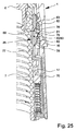
図24は、アンロック位置での更に別の実施形態のネブライザ1、ロッキングデバイス26の部分概略断面を示している。図25は、それぞれの断面にロック位置又はロック状態でのロッキングデバイス26を示している。
FIG. 24 shows a partial schematic cross section of a further embodiment of the
更に別の実施形態において、ロッキング要素66は、好ましくは半径方向(のみ)に移動可能な摺動ブロックとして形成されることが好ましい。
In yet another embodiment, the locking
更に別の実施形態において、ロッキングデバイス26は、好ましくは、起動するために少なくとも1つの傾斜面78を通じてロッキング要素66と相互作用する、特に、ロッキング要素66をロッキング位置内に半径方向に移動するロッキング部材77を含む。
In yet another embodiment, the locking
好ましくは、ロッキング要素66は、ここではロッキング部材77又は傾斜面78のピッタリした係合又は起動によってロッキング位置内に移動する。
Preferably, the locking
ロッキング要素66は、好ましくは、アンロック位置からロック位置内に能動的に移動可能であり、及び/又はその逆も可能である。
The locking
ロッキング要素66は、好ましくは、図25に概略的に示すように、ピッタリした係合により、及び/又はロッキング部材77の逆の又は上方の移動及び/又はロッキング要素66のそれぞれの好ましくは傾斜制御面79の係合又は当接により、アンロック位置に戻るように移動可能である。
The locking
更に別の実施形態において、制御面79は、好ましくは、ロッキング部材77の線形及び/又は軸線方向移動をアンロック位置内へのロッキング要素66の横方向又は半径方向、ここではアンロッキング又は内向き移動に変換するために、図25に概略的に示すように、ロッキング部材77のそれぞれの壁又は傾斜部分80と協働する。
In yet another embodiment, the
好ましくは、制御面79は、ロッキング要素66の制御部分81に又はそれによって形成される。しかし、他の構成的ソリューションが可能である。例えば、傾斜制御面79は、これに代えて又はこれに加えて、ロッキング移動、ここでは半径方向外向きとは反対の正の移動、ここでは半径方向内向き移動を実現するために、傾斜部分80又はロッキング部材77に又はそれによって形成するか又は構築することができる。
Preferably,
一般的に、ロッキング要素66は、好ましくは、回転阻止又はロック状態を解除するためにロッキング位置からアンロッキング位置内へ可逆である。これは、本発明の実施形態において、好ましくは、ネブライザ1又はそのハウジング部分18を閉じる時に軸線方向に当接するアクチュエータ71によるロッキング部材77の軸線方向起動又は上方移動によって実現される。しかし、他の構成的ソリューションもまた可能である。
In general, the locking
軸線方向移動又は起動を半径方向移動に変換する上記原理は、好ましくは、反対方向に、すなわち、ロッキング要素66を起動又はロックする時にも当て嵌まる。
The above principle of converting axial movement or actuation into radial movement preferably also applies in the opposite direction, ie when activating or locking the locking
更に別の実施形態において、傾斜面78は、好ましくは、ロッキング要素66に又はそれによって形成されたカウンター部分82と協働する。
In yet another embodiment, the
ロッキング部材77の線形又は軸線方向移動を望ましい横方向又は半径方向ロッキング移動、ここでは半径方向外向き移動に変換するために、カウンター部分82又はロッキング要素66に又はそれにより、傾斜面78及び/又は対応するカウンター面を形成することも可能である。
In order to convert the linear or axial movement of the locking
更に別の実施形態において、ロッキング部材77は、好ましくは、正確にロッキング要素66を移動又は起動させ及び/又は傾斜なく又は傾斜を最小限にしてロッキング要素66を移動するために、好ましくは、2つの傾斜面78を含み、ロッキング要素66は、好ましくは、2つのカウンター部分82を含む。従って、ロッキング部材77の線形又は軸線方向移動又は起動は、ロッキング要素66の横方向又は横断方向又は半径方向又は外向き移動を図25に示すロック位置内に変換することができる。
In yet another embodiment, the locking
好ましくは、ロッキング要素66は、少なくとも本質的に平面又は軸線方向軸受部分又は面83、特に2つの面83によってロック位置に保持又はロックされる。
Preferably, the locking
好ましくは、ロッキング部材77は、本質的に平面又は軸線方向軸受面83を形成し、ロック位置にロッキング要素66を保持又はロックする。
Preferably, locking
特に、カウンター部分82は、ロッキング部材77の軸線方向、ここでは下向き移動中にそれぞれの傾斜面78に沿って移動し、次に、それぞれの軸受面83に到達することができる。この状態は、図25に示されている。
In particular, the
一般的に、ロッキング要素66は、内側部分17の円周の回り又はその上に配置され及び/又は好ましくは1又は2以上のロッキングバネ67によってロック位置内に同時に及び/又は軸線方向に付勢された1つ又は複数の係合部分69を有する少なくとも1つ又はそれよりも多くのロッキング要素66で構成され、又はロッキングデバイス26は、それを含むことができる。この修正は示されていないが、ロック状態での非常にセキュアな阻止を可能にすると考えられる。
In general, the locking
上述のように、説明する実施形態の個々の特徴、態様、及び/又は原理は、必要に応じて互いに組み合わせることもでき、図示したネブライザ1において特に使用することができるが、類似の又は異なるネブライザにおいても使用することもできる。
As mentioned above, the individual features, aspects and / or principles of the described embodiments can also be combined with one another as required and can be used in particular in the illustrated
様々な実施形態の特徴は、組み合わせるか又は交換することができる。 The features of the various embodiments can be combined or interchanged.
独立型機器などとは異なり、提案するネブライザ1は、好ましくは、携帯式であるように設計され、特に移動式手動デバイスである。
Unlike stand-alone equipment and the like, the proposed
しかし、提案するソリューションは、本明細書で具体的に説明するネブライザ1だけではなく、他のネブライザ又は吸入器、例えば、粉末吸入器又はいわゆる計量式投薬吸入器に使用することもできる。
However, the proposed solution can also be used for other nebulizers or inhalers, such as a powder inhaler or a so-called metered dose inhaler, as well as the
好ましくは、流体2は、上述のような液体、特に、水性医薬製剤又はエタノール医薬薬剤である。しかし、それはまた、何らかの他の医薬薬剤又は懸濁液などである場合がある。
Preferably, the
代替実施形態により、流体2はまた、粒子又は粉末を含むことができる。この場合に、排出ノズル12の代わりに、何らかの他の種類の供給デバイス、特に、流体を粉末などに供給するための排出開口部(図示せず)又は供給チャネル(図示せず)をマウスピース13の中に設けることができる。任意的な空気供給開口部15は、次に、マウスピース13を通して呼吸又は吸入するのに十分な容積の空気流を発生又は可能にするために、好ましくは、並行して周囲空気を供給するように機能する。
According to alternative embodiments, the
必要に応じて、流体2は、推進剤ガスを使用して噴霧化することもできる。
If desired, the
好ましい薬液2の好ましい原料及び/又は製剤は、特に、本明細書に引用によって組み込まれているWO 2009/115200 A1、好ましくは25〜40ページに、又はEP 2,614,848 A1、段落0040〜0087に列挙されている。特に、それらは、水性又は非水性溶液、混合液、又はエタノール含有又はいかなる溶剤も含まない製剤などである場合がある。
Preferred raw materials and / or formulations of the preferred
参照番号のリスト
1 ネブライザ
2 流体
3 容器
4 バッグ
5 圧力発生器
6 ホルダ
7 駆動バネ
8 阻止要素
9 搬送チューブ
10 逆止弁
11 圧力チャンバ
12 ノズル
13 マウスピース
14 エアロゾル
15 空気供給開口部
16 上側ハウジング部分
17 内側部分
17a 内側部分の上側部分
17b 内側部分の下側部分
18 ハウジング部分(下側部分)
19 保持要素
20 曝気バネ
21 容器ベース
22 穿孔要素
23 通気孔
24 ネブライザハウジング
25 表示デバイス
26 ロッキングデバイス
27 マウスピースカバー
28 ヘッド
29 容器ハウジング
30 容器縁部
31 表示器ハウジング
31a 窓
32 把持セクション
33 上側部分
34 下側部分
35 表示要素
36 起動要素
37 マーキング
38 起動アーム
39 起動部分
40 伝達部
41 歯車
42 ウォーム
43 歯
44 心棒セクション
45 軸受セクション
46 軸受部分
47 起動バネ
48 穿孔部分
49 穿孔先端
50 ホイル
51 窪み
52 駆動部分
53 底部
54 挿入開口部
55 支持構造
56 可撓性アーム
57 溝
58 ラチェット
59 面
60 突起
61 阻止部分
62 制御部分
63 制御部
64 保持ノーズ
65 保持凹部
66 ロッキング要素
67 ロッキングバネ
68 ポケット
69 係合部分
70 カバー
71 アクチュエータ
72 摺動ガイド
73 ベース部分
74 保護体
75 溝
76 突起
77 ロッキング部材
78 傾斜面
79 制御面
80 傾斜部分
81 制御部分
82 カウンター部分
83 軸受面
List of
Claims (24)
前記流体(2)を収容する容器(3)を有し、該容器(3)は、別の容器(3)と取替可能であり、
搬送要素、圧力チャンバ(11)及びノズル(12)を備える、前記流体(2)を搬送及び噴霧するための送出機構を有し、前記ネブライザ(1)の引張工程において、前記容器(3)は軸線方向に下向きに移動し、流体(2)は前記搬送要素によって前記容器(3)から出て前記圧力チャンバ(11)に入るように搬送され、噴霧工程において前記容器(3)は軸線方向に上向きに移動し、前記圧力チャンバ(11)中の前記流体(2)は加圧され、前記ノズル(12)を通じて小出しされ、
前記容器(3)を用いて実施されたか又は依然として可能な使用回数を計数し、及び/又は示すための表示デバイス(25)を有し、該表示デバイス(25)は前記容器(3)に固定され又は前記容器(3)に配置され、そして該表示デバイス(25)は、前記引張工程の間及び前記噴霧工程の間、前記ネブライザ(1)内で前記容器(3)と共に軸線方向に移動可能であり、該表示デバイス(25)は表示要素(35)及び、前記表示デバイス(25)の軸線方向の移動に応じて前記表示要素(35)の回転送りを起動する起動要素(36)及び、前記表示要素(35)を回転送りするための伝達部(40)を備え、
現在の容器(3)を用いて予め決められた使用回数が到達されたか又は超過された後にのみ前記ネブライザ(1)の更なる使用を阻止するようになったロッキングデバイス(26)と、
を含み、
前記ネブライザ(1)が、前記ネブライザ(1)の上側ハウジング部分(16)に対する下側ハウジング部分(18)の回転によって引張状態になり、この回転は、前記ネブライザ(1)の前記引張工程を完了するために必要な全回転角度の回転を含み、
前記ロッキングデバイス(26)は、前記回転を前記全回転角度の後半の中間回転位置で阻止するようになっている、
ことを特徴とするネブライザ(1)。 A nebulizer (1) for a fluid (2),
A container (3) containing said fluid (2) , said container (3) being replaceable with another container (3);
A delivery mechanism for transporting and spraying said fluid (2), comprising a transport element, a pressure chamber (11) and a nozzle (12), wherein in the tensioning step of said nebulizer (1), said container (3) Moving downward in the axial direction, the fluid (2) is conveyed by the conveying element out of the container (3) and into the pressure chamber (11), the container (3) being axially displaced in the spraying process Moving upward, the fluid (2) in the pressure chamber (11) is pressurized and dispensed through the nozzle (12);
A display device (25) for counting and / or indicating the number of uses performed or still possible with said container (3), said display device (25) being fixed to said container (3) Or the display device (25) is axially movable with the container (3) in the nebulizer (1) during the tensioning process and during the spraying process. The display device (25) includes a display element (35), and an activation element (36) that activates rotational feed of the display element (35) in accordance with the axial movement of the display device (25); A transmission unit (40) for rotating and feeding the display element (35);
A locking device (26) adapted to prevent further use of said nebulizer (1) only after a predetermined number of uses has been reached or exceeded with the current container (3);
Including
Wherein the nebulizer (1), becomes in tension by the rotation of the lower housing portion (18) relative to the upper housing part (16) of the nebulizer (1), this rotation is completed the pulling step of the nebulizer (1) Including the full rotation angle required to
Wherein the locking device (26) is adapted to the rotation to be stopped at an intermediate rotational position of the second half of the full rotation angle,
A nebulizer (1), characterized in that:
前記ロッキングデバイス(26)は、前記ロッキング要素(66)が前記ロッキング位置にあるとき、前記ネブライザ(1)の更なる使用を阻止し、前記前記ロッキング要素(66)が前記非ロッキング位置にあるとき、前記ネブライザ(1)の更なる使用を阻止しないことを特徴とする請求項1に記載のネブライザ(1)。 The locking device (26) includes a locking element (66) movable between a locking position and a non-locking position;
The locking device (26) prevents further use of the nebulizer (1) when the locking element (66) is in the locking position and when the locking element (66) is in the non-locking position. The nebulizer (1) according to claim 1 , characterized in that it does not prevent further use of the nebulizer (1).
前記ロッキング位置において、前記ロッキング要素(66)は、前記ネブライザ(1)の前記上側ハウジング部分(16)に対する前記ネブライザ(1)の前記内側部分(17)の回転を阻止することを特徴とする請求項2から請求項5のいずれか1項に記載のネブライザ(1)。 The nebulizer (1) comprises an inner part (17) to which the lower housing part (18) is releasably mounted, the lower housing part (18) being adapted to replace the container (3) with the inner part. The lower housing part (18) surrounds the inner part (17) when the lower housing part (18) is attached to the inner part (17) and is removable from the part (17). When the side housing part (18) is rotated relative to the upper housing part (16), the inner part (17) rotates with the lower housing part (18);
In said locking position, said locking element (66) prevents rotation of said inner part (17) of said nebulizer (1) relative to said upper housing part (16) of said nebulizer (1). The nebulizer (1) according to any one of claims 2 to 5.
前記容器(3)を取り替えるために、前記ネブライザ(1)の他の部分から取り外し可能な前記下側ハウジング部分(18)は、前記予め決められた使用回数分使用されたことを示す前記表示デバイス(25)を有する各容器(3)が新しいか又はリセットされた表示デバイス(25)を有する新しい容器(3)と取り替えられた後に、前記ロッキングデバイス(26)が自動的に解除されるように、前記ネブライザ(1)の内側部分(17)に完全に取り付けることができることを特徴とする請求項1から請求項19のいずれか1項に記載のネブライザ(1)。 The display device (25) only allows the locking device (26) to use the nebulizer (1) from further use when a predetermined number of uses has been reached or exceeded with each container (3). Let them lock,
The lower housing part (18), which can be detached from another part of the nebulizer (1) to replace the container (3), the display device indicating that it has been used for the predetermined number of uses after replaced with a new container (3) having a respective container (3) is new or reset the display device having a (25) (25) such that said locking device (26) is automatically released 20. Nebulizer (1) according to any of the preceding claims, characterized in that it can be completely attached to the inner part (17) of the nebulizer (1) .
Applications Claiming Priority (3)
| Application Number | Priority Date | Filing Date | Title |
|---|---|---|---|
| EP14001603 | 2014-05-07 | ||
| EP14001603.1 | 2014-05-07 | ||
| PCT/EP2015/000900 WO2015169428A2 (en) | 2014-05-07 | 2015-05-04 | Nebulizer |
Publications (2)
| Publication Number | Publication Date |
|---|---|
| JP2017515562A JP2017515562A (en) | 2017-06-15 |
| JP6643252B2 true JP6643252B2 (en) | 2020-02-12 |
Family
ID=50679834
Family Applications (5)
| Application Number | Title | Priority Date | Filing Date |
|---|---|---|---|
| JP2016566735A Active JP6526057B2 (en) | 2014-05-07 | 2015-05-04 | Nebulizer and container |
| JP2016566897A Active JP6745225B2 (en) | 2014-05-07 | 2015-05-04 | Container, display device, and nebulizer |
| JP2016566222A Active JP6643252B2 (en) | 2014-05-07 | 2015-05-04 | Nebulizer |
| JP2016566742A Active JP6594340B2 (en) | 2014-05-07 | 2015-05-04 | Nebulizer, display device, and container |
| JP2019087355A Active JP6992023B2 (en) | 2014-05-07 | 2019-05-07 | Nebulizer and container |
Family Applications Before (2)
| Application Number | Title | Priority Date | Filing Date |
|---|---|---|---|
| JP2016566735A Active JP6526057B2 (en) | 2014-05-07 | 2015-05-04 | Nebulizer and container |
| JP2016566897A Active JP6745225B2 (en) | 2014-05-07 | 2015-05-04 | Container, display device, and nebulizer |
Family Applications After (2)
| Application Number | Title | Priority Date | Filing Date |
|---|---|---|---|
| JP2016566742A Active JP6594340B2 (en) | 2014-05-07 | 2015-05-04 | Nebulizer, display device, and container |
| JP2019087355A Active JP6992023B2 (en) | 2014-05-07 | 2019-05-07 | Nebulizer and container |
Country Status (33)
| Country | Link |
|---|---|
| US (4) | US10716906B2 (en) |
| EP (7) | EP3139982B1 (en) |
| JP (5) | JP6526057B2 (en) |
| KR (5) | KR20230018542A (en) |
| CN (6) | CN106232165B (en) |
| AP (1) | AP2016009486A0 (en) |
| AR (2) | AR100963A1 (en) |
| AU (6) | AU2015258107B2 (en) |
| BR (5) | BR122022010094B1 (en) |
| CA (4) | CA2945018C (en) |
| CL (5) | CL2016002803A1 (en) |
| DK (4) | DK3928818T3 (en) |
| EA (5) | EA033013B1 (en) |
| ES (4) | ES2957901T3 (en) |
| FI (1) | FI3928818T3 (en) |
| HR (2) | HRP20230370T1 (en) |
| HU (4) | HUE053905T2 (en) |
| IL (4) | IL247926B (en) |
| LT (2) | LT3928818T (en) |
| MX (5) | MX2016014401A (en) |
| MY (1) | MY187485A (en) |
| NZ (2) | NZ724449A (en) |
| PE (2) | PE20161564A1 (en) |
| PH (5) | PH12016502192B1 (en) |
| PL (4) | PL3928818T3 (en) |
| PT (3) | PT3139982T (en) |
| RS (2) | RS63171B1 (en) |
| SG (2) | SG11201608891RA (en) |
| SI (2) | SI3928818T1 (en) |
| TW (1) | TWI607770B (en) |
| UA (1) | UA121114C2 (en) |
| UY (1) | UY36115A (en) |
| WO (4) | WO2015169759A1 (en) |
Families Citing this family (49)
| Publication number | Priority date | Publication date | Assignee | Title |
|---|---|---|---|---|
| EP2077132A1 (en) | 2008-01-02 | 2009-07-08 | Boehringer Ingelheim Pharma GmbH & Co. KG | Dispensing device, storage device and method for dispensing a formulation |
| EP2662472B1 (en) | 2009-03-31 | 2019-02-27 | Boehringer Ingelheim International Gmbh | Method for coating a surface of a component |
| EP3508239B1 (en) | 2009-05-18 | 2020-12-23 | Boehringer Ingelheim International GmbH | Adapter, inhalant apparatus and atomizer |
| SG181050A1 (en) | 2009-11-25 | 2012-07-30 | Boehringer Ingelheim Int | Nebulizer |
| US10016568B2 (en) | 2009-11-25 | 2018-07-10 | Boehringer Ingelheim International Gmbh | Nebulizer |
| JP5658268B2 (en) | 2009-11-25 | 2015-01-21 | ベーリンガー インゲルハイム インターナショナル ゲゼルシャフト ミット ベシュレンクテル ハフツング | Nebulizer |
| WO2011160932A1 (en) | 2010-06-24 | 2011-12-29 | Boehringer Ingelheim International Gmbh | Nebulizer |
| WO2012130757A1 (en) | 2011-04-01 | 2012-10-04 | Boehringer Ingelheim International Gmbh | Medical device comprising a container |
| US9827384B2 (en) | 2011-05-23 | 2017-11-28 | Boehringer Ingelheim International Gmbh | Nebulizer |
| WO2013152894A1 (en) | 2012-04-13 | 2013-10-17 | Boehringer Ingelheim International Gmbh | Atomiser with coding means |
| WO2015018904A1 (en) | 2013-08-09 | 2015-02-12 | Boehringer Ingelheim International Gmbh | Nebulizer |
| PL2835146T3 (en) | 2013-08-09 | 2021-04-06 | Boehringer Ingelheim International Gmbh | Nebulizer |
| WO2015169759A1 (en) | 2014-05-07 | 2015-11-12 | Boehringer Ingelheim International Gmbh | Nebulizer and container |
| BR112016023983B1 (en) | 2014-05-07 | 2022-10-18 | Boehringer Ingelheim International Gmbh | CONTAINER FOR A NEBULIZER, NEBULIZER FOR A FLUID AND METHOD FOR CONNECTING A CONTAINER TO AN INDICATOR DEVICE |
| US10722666B2 (en) | 2014-05-07 | 2020-07-28 | Boehringer Ingelheim International Gmbh | Nebulizer with axially movable and lockable container and indicator |
| WO2017080895A1 (en) | 2015-11-09 | 2017-05-18 | Boehringer Ingelheim International Gmbh | Nebulizer and container |
| DE102015120948A1 (en) * | 2015-12-02 | 2017-06-08 | Alfred Von Schuckmann | Hand-held device for dispensing a pharmaceutical substance and counter and screw cap for such a hand-held device |
| DE102015120949A1 (en) * | 2015-12-02 | 2017-06-08 | Alfred Von Schuckmann | Inhaler for powdered substances and counter for an inhaler |
| GB201605102D0 (en) | 2016-03-24 | 2016-05-11 | Nicoventures Holdings Ltd | Mechanical connector for electronic vapour provision system |
| CN109259332B (en) * | 2016-05-06 | 2021-06-25 | 卓尔悦欧洲控股有限公司 | Atomizing device and have this atomizing device's electron cigarette |
| US11369760B2 (en) * | 2016-08-24 | 2022-06-28 | Anovent Pharmaceutical (U.S.), Llc | Inhalation atomizer comprising a blocking function and a counter |
| JP6733442B2 (en) * | 2016-09-08 | 2020-07-29 | オムロンヘルスケア株式会社 | Mesh nebulizer |
| EP4005618B1 (en) * | 2016-12-21 | 2024-04-24 | Boehringer Ingelheim International GmbH | Nebulizer and cartridge |
| DE102017100012A1 (en) * | 2017-01-02 | 2018-07-05 | Nebu-Tec Med. Produkte Eike Kern Gmbh | Nebulizer unit with directly connectable ampoule |
| US10556072B2 (en) * | 2017-01-31 | 2020-02-11 | Dunan Microstaq, Inc. | Metering device for a metered dose inhaler |
| US20210113784A1 (en) * | 2017-03-20 | 2021-04-22 | Vectura Delivery Devices Limited | Container for cleaning the membrane of a nebulizer |
| NZ757052A (en) * | 2017-03-20 | 2020-08-28 | Vectura Delivery Devices Ltd | Method and container for cleaning the membrane of a nebulizer |
| CN110944699B (en) * | 2017-07-21 | 2022-11-25 | 勃林格殷格翰国际有限公司 | Nebulizer and reservoir |
| AU2018303702B2 (en) * | 2017-07-21 | 2023-09-21 | Boehringer Ingelheim International Gmbh | Nebulizer |
| US20190054260A1 (en) * | 2017-08-17 | 2019-02-21 | Monzano Group LLC | Nebulizer devices and methods |
| US10370176B2 (en) | 2017-09-12 | 2019-08-06 | Wd-40 Company | Child resistant aerosol actuator |
| CN108041008B (en) * | 2017-12-08 | 2020-11-27 | 台州市协丰机械有限公司 | Electric sprayer and shell mounting structure thereof |
| WO2019121386A1 (en) * | 2017-12-18 | 2019-06-27 | Boehringer Ingelheim International Gmbh | Device for putting an inhaler into a triggering-ready state |
| EP3501582B1 (en) * | 2017-12-21 | 2022-04-27 | Boehringer Ingelheim International GmbH | Nebulizer and cartridge |
| CN111526909B (en) * | 2017-12-22 | 2023-07-25 | 索芙特海尔公司 | Barrier device |
| CN112292169B (en) | 2018-06-15 | 2023-08-04 | 勃林格殷格翰国际有限公司 | System, cartridge and method |
| US10421086B1 (en) * | 2018-06-19 | 2019-09-24 | Christine Kuligowski | Reusable dry erase spray paint can |
| WO2020064372A1 (en) * | 2018-09-27 | 2020-04-02 | Shl Medical Ag | Activation mechanism for an aerosol dispenser |
| CN111135403A (en) * | 2018-11-02 | 2020-05-12 | 正大天晴药业集团股份有限公司 | Capsule type dry powder inhaler |
| CN111195382B (en) * | 2018-11-16 | 2022-04-19 | 微邦科技股份有限公司 | Locking structure of atomization drug delivery device |
| EP3886954A4 (en) * | 2018-11-30 | 2022-09-07 | Noble International, Inc. | Respiratory inhaler cartridge placement training device |
| MX2021012125A (en) * | 2019-04-01 | 2021-11-03 | Ppg Arch Finishes Inc | Pneumatic spray gun cartridge. |
| CN113038982A (en) * | 2019-07-29 | 2021-06-25 | 上海谷森医药有限公司 | Cartridge for aerosol inhalation with single-layer container and nozzle-shaped cap |
| CN215515024U (en) * | 2020-06-30 | 2022-01-14 | 微邦科技股份有限公司 | Sprayer and storage device |
| JP2023532975A (en) | 2020-07-03 | 2023-08-01 | ベーリンガー インゲルハイム インターナショナル ゲゼルシャフト ミット ベシュレンクテル ハフツング | nebulizer |
| CN113967299A (en) * | 2020-07-22 | 2022-01-25 | 苏州天健云康信息科技有限公司 | Atomization device and counting module for atomization device |
| GB2626538A (en) * | 2023-01-24 | 2024-07-31 | Merxin Ltd | Cartridge |
| CN117180564B (en) * | 2023-07-24 | 2024-04-19 | 齐鲁制药有限公司 | Counter with locking mechanism and sprayer comprising counter |
| CN117205412B (en) * | 2023-11-07 | 2024-02-13 | 正大天晴(广州)医药有限公司 | Dose indicator |
Family Cites Families (608)
| Publication number | Priority date | Publication date | Assignee | Title |
|---|---|---|---|---|
| US1828864A (en) | 1923-02-20 | 1931-10-27 | Gilmont Products Corp | Method of filling bicompartment collapsible tubes |
| GB414953A (en) | 1932-12-24 | 1934-08-16 | Josef Schoene | Medical injection syringe |
| US2127401A (en) | 1937-11-15 | 1938-08-16 | Gillican Charles Crum | Method of packaging rosin |
| US2161071A (en) | 1938-05-02 | 1939-06-06 | Zellerbach Paper Company | Method of packing frozen food |
| US2321428A (en) | 1939-04-25 | 1943-06-08 | Ferdinand G Schloz | Nozzle |
| US2329311A (en) | 1940-06-05 | 1943-09-14 | Harry F Waters | Method of producing liquid-containing packages |
| US2362103A (en) | 1941-01-04 | 1944-11-07 | Arthur E Smith | Ampoule |
| US2651303A (en) | 1948-11-13 | 1953-09-08 | Richard S Johnson | Inhaler |
| US2720969A (en) | 1953-12-10 | 1955-10-18 | Becton Dickinson Co | Package and mounting for hypodermic syringe assembly |
| DK83175C (en) | 1955-07-04 | 1957-07-22 | Grosserer Gorm Tage Hansen | Air control systems for greenhouses. |
| US2974880A (en) | 1955-11-15 | 1961-03-14 | Drackett Co | Aerosol spray head |
| US2793776A (en) | 1956-05-23 | 1957-05-28 | Lipari Michael | Container attachment for providing a compartmental dispensing receptacle |
| US3172568A (en) | 1959-03-27 | 1965-03-09 | Modern Lab Inc | Pressurized dispensing device |
| US3032823A (en) | 1960-05-26 | 1962-05-08 | Sherman Plastics Corp | Method of forming plastic articles |
| GB951228A (en) | 1961-09-26 | 1964-03-04 | Ici Ltd | Packaging process |
| FR1314002A (en) | 1961-11-24 | 1963-01-04 | Method and device for dispensing a non-compacted substance | |
| US3299603A (en) | 1962-03-12 | 1967-01-24 | Continental Can Co | Method of filling pouches |
| NL297349A (en) | 1962-08-31 | |||
| US3354883A (en) | 1965-03-08 | 1967-11-28 | Southerland Elizabeth Lee | Disposable syringe having frangible means for mixing plural medicaments |
| US3440144A (en) | 1965-05-21 | 1969-04-22 | Andersen Prod H W | Method and apparatus for checking and testing the effectiveness of sterilization |
| US3457694A (en) | 1966-08-25 | 1969-07-29 | Hideo Tatibana | Method of and apparatus for fusion sealing the opening of flexible plastic bottle-like containers |
| US3491803A (en) | 1966-10-03 | 1970-01-27 | Haskon Inc | Machine for filling with liquids containers having deformable side walls |
| FR1502925A (en) | 1966-10-12 | 1967-11-24 | Vaporisateurs Marcel Franck | Improvements to piston pumps for dispensing liquids or fluid pastes |
| GB1230472A (en) | 1967-07-10 | 1971-05-05 | ||
| US3590557A (en) | 1968-03-07 | 1971-07-06 | Fr Hesser Maschinenfabrick Ag | Apparatus for closing packaging containers with elastically deformable walls |
| US3580249A (en) | 1968-09-16 | 1971-05-25 | Kentaro Takaoka | Aerosol nebulizers |
| US3674028A (en) | 1969-06-04 | 1972-07-04 | Ims Ltd | Multi-mix |
| US3858580A (en) | 1969-06-04 | 1975-01-07 | Ims Ltd | Intravenous container mixing assembly |
| BE751383R (en) | 1969-08-12 | 1970-12-03 | Oreal | PERFECTIONED VALVE FOR PRESSURIZED CONTAINER DISPENSER OF SEVERAL PRODUCTS |
| US3655096A (en) | 1969-10-22 | 1972-04-11 | Pillsbury Co | Container for diluting and dispensing material |
| US3949751A (en) | 1970-03-03 | 1976-04-13 | Fisons Limited | Method and device for dispensing medicament to the body |
| US3674060A (en) | 1970-12-14 | 1972-07-04 | Continental Can Co | Apparatus for filling and adjusting the contents level in flexible containers |
| BE788194A (en) | 1971-08-31 | 1973-02-28 | Thomae Gmbh Dr K | DEVICE FOR THE ADMINISTRATION OF MECHANICALLY DOSE QUANTITIES OF LIQUID OR SOLUTION MEDICINAL PRODUCTS |
| US3861851A (en) | 1971-12-08 | 1975-01-21 | Schiemann Dr Wolfram | Apparatus for moulding the neck of an extruded hollow body |
| US3802604A (en) | 1972-02-28 | 1974-04-09 | Oreal | Device for storing two products separately and dispensing them simultaneously |
| DE2221101C3 (en) | 1972-04-28 | 1975-05-15 | Wolf-Geraete Gmbh, 5240 Betzdorf | Bottle-like mixing container |
| US3933279A (en) | 1972-11-28 | 1976-01-20 | Ciba-Geigy Corporation | Aerosol dispenser for fluid products comprising a piston pump assembly for generating compressed air |
| US3946732A (en) | 1973-08-08 | 1976-03-30 | Ampoules, Inc. | Two-chamber mixing syringe |
| US3951310A (en) | 1974-02-11 | 1976-04-20 | V.C.A. Corporation | Spring-charged aerosol dispenser |
| US3973603A (en) | 1974-06-18 | 1976-08-10 | Franz Henry H | Control for filling flexible bottles or containers |
| DK140801B (en) | 1975-01-15 | 1979-11-19 | Nordisk Insulinlab | Process for the preparation of a stable long-acting insulin preparation. |
| US3924741A (en) | 1975-03-04 | 1975-12-09 | Gibson Ass Inc | Two-compartment container |
| US3953995A (en) | 1975-05-27 | 1976-05-04 | Haswell John W | Means for making double groove pulleys |
| US4153689A (en) | 1975-06-13 | 1979-05-08 | Takeda Chemical Industries, Ltd. | Stable insulin preparation for nasal administration |
| US4012472A (en) | 1975-07-17 | 1977-03-15 | Arbrook, Inc. | Medical fluids container |
| US4174035A (en) | 1975-09-04 | 1979-11-13 | Georg Wiegner | Two-component container and package |
| US4036439A (en) | 1975-09-24 | 1977-07-19 | Newman-Green, Inc. | Spray head for nebulization of fluids |
| US4067499A (en) | 1976-02-17 | 1978-01-10 | Cohen Milton J | Non-aerosol continuous spray dispenser |
| US4126559A (en) | 1976-03-30 | 1978-11-21 | Pall Corporation | Pharmaceutical filter |
| US4094317A (en) | 1976-06-11 | 1978-06-13 | Wasnich Richard D | Nebulization system |
| US4048997A (en) | 1976-11-01 | 1977-09-20 | Mpl, Inc. | Syringe with actinic radiation protection |
| US4099049A (en) * | 1976-11-10 | 1978-07-04 | Pitney-Bowes, Inc. | Ascending register lockout system for a postage meter |
| IT1075249B (en) | 1976-12-10 | 1985-04-22 | Ottina Luigi | TWO-CONTAINER DEVICE FOR THE INDEPENDENT STORAGE OF TWO COMPONENTS AND THE SYSTEMS PREPARATION OF A PRODUCT WITH THESE TWO COMPONENTS |
| US4177938A (en) | 1977-06-30 | 1979-12-11 | Brina Guido J | Container with mixing cartridge |
| US4178928A (en) | 1977-08-10 | 1979-12-18 | Tischlinger Edward A | Self injector |
| US4245788A (en) | 1978-03-20 | 1981-01-20 | Wright Hershel E | Dispensing device for fluid material |
| US4195730A (en) | 1978-06-20 | 1980-04-01 | General Foods Corporation | Container having separate storage facilities for two materials |
| CA1097276A (en) | 1978-12-15 | 1981-03-10 | Marcel J. H. Staar | Package for storing and spraying small amounts of liquids |
| US4315570A (en) | 1979-01-04 | 1982-02-16 | Jules Silver | Two-compartment container with means for dispersing contents of one compartment into the other compartment |
| JPS5819535B2 (en) | 1979-04-16 | 1983-04-19 | 本州製紙株式会社 | How to seal a sealed container |
| EP0018609B1 (en) | 1979-04-30 | 1983-09-21 | Hoechst Aktiengesellschaft | Aqueous solutions of proteins stable against denaturization, process for their manufacture, and their utilization |
| DK374579A (en) | 1979-09-07 | 1981-03-08 | Nordisk Insulinlab | PROCEDURE FOR THE PREPARATION OF AN INJUCABLE INSULIN PREPARATION |
| JPS5684246A (en) | 1979-11-28 | 1981-07-09 | Toppan Printing Co Ltd | Vessel |
| US4377106A (en) | 1980-06-30 | 1983-03-22 | Realex Corporation | Tamper-resistant locking clip for dispensing pumps |
| GB2083382B (en) | 1980-09-08 | 1984-06-20 | Metal Box Co Ltd | Forming can bodies |
| DE3118783C2 (en) | 1981-05-12 | 1986-02-20 | Cantec, Inc., Fort Worth, Tex. | Device for beading the body of a sheet metal container |
| AU558474B2 (en) | 1981-07-17 | 1987-01-29 | Nordisk Insulinlaboratorium | A stable aqueous, therapeutic insulin preparation and a process for preparing it |
| US4516967A (en) | 1981-12-21 | 1985-05-14 | Kopfer Rudolph J | Wet-dry compartmental syringe |
| EP0102976A1 (en) | 1982-03-03 | 1984-03-21 | Nordisk Insulinlaboratorium | A process for producing an insulin preparation |
| GB2123481B (en) | 1982-06-19 | 1985-04-17 | Lucas Ind Plc | C i engine fuel injection nozzles |
| US4456016A (en) | 1982-07-01 | 1984-06-26 | Trutek Research, Inc. | Inhalation valve |
| US4515586A (en) | 1982-11-30 | 1985-05-07 | Abbott Laboratories | Powder syringe mixing system |
| US4476116A (en) | 1982-12-10 | 1984-10-09 | Syntex (U.S.A.) Inc. | Polypeptides/chelating agent nasal compositions having enhanced peptide absorption |
| USRE33444E (en) | 1984-01-09 | 1990-11-20 | Fluid treating for removal of components or for transfer of heat, momentum-apparatus and method | |
| NZ209900A (en) | 1984-10-16 | 1989-08-29 | Univ Auckland | Automatic inhaler |
| US4964540A (en) | 1984-10-17 | 1990-10-23 | Exxel Container, Inc. | Pressurized fluid dispenser and method of making the same |
| US4858830A (en) | 1985-03-20 | 1989-08-22 | Turbo Tek Enterprises, Inc. | Spraying device having an additive fluid dispenser at an exit end |
| US4682734A (en) | 1985-03-20 | 1987-07-28 | Turbo Tek Enterprises, Inc. | Spraying device having controlled additive fluid feed and a telescoping spray tube assembly |
| EP0386800A1 (en) | 1985-03-20 | 1990-09-12 | Turbo Tek Enterprises, Inc. | Spraying device having controlled additive fluid feed and a telescoping spray tube assembly |
| US4603794A (en) | 1985-03-29 | 1986-08-05 | Battelle Development Corporation | Pressure multiplying dispenser |
| IT1185850B (en) | 1985-08-02 | 1987-11-18 | Zambon Spa | DROP TANK CAP FOR BOTTLES |
| JPS6274364A (en) | 1985-09-27 | 1987-04-06 | 株式会社 ニツシヨ− | Medical applicance |
| US4727985A (en) | 1986-02-24 | 1988-03-01 | The Boc Group, Inc. | Mixing and dispensing apparatus |
| DE3767615D1 (en) | 1986-03-10 | 1991-02-28 | Kurt Burghart | PHARMACEUTICAL AND METHOD FOR THE PRODUCTION THEREOF. |
| DE3611690A1 (en) | 1986-04-08 | 1987-10-15 | Pfeiffer Erich Gmbh & Co Kg | DISCHARGE DEVICE FOR MIXED MEDIA |
| DK179286D0 (en) | 1986-04-18 | 1986-04-18 | Nordisk Gentofte | INSULIN PREPARATION |
| US4749082A (en) | 1986-05-05 | 1988-06-07 | Imperial Schrade Corp. | Knife transport/display package |
| FR2604363A1 (en) | 1986-09-30 | 1988-04-01 | Merieux Inst | DEVICE FOR INJECTING SUBSTANCES, ESPECIALLY MEDICINAL PRODUCTS |
| FI89458C (en) | 1986-11-06 | 1993-10-11 | Leiras Oy | INHALERINGSANORDNING |
| US4796614A (en) | 1987-02-26 | 1989-01-10 | Trutek Research, Inc. | Collapsible inhalation valve |
| US4952310A (en) | 1987-03-03 | 1990-08-28 | Mcmahan Anthony A | Intrachannel clarifier |
| GB8710067D0 (en) | 1987-04-28 | 1987-06-03 | British Telecomm | Optical device |
| JP2656944B2 (en) | 1987-04-30 | 1997-09-24 | クーパー ラボラトリーズ | Aerosolization of protein therapeutics |
| DE3721308A1 (en) | 1987-06-27 | 1989-01-05 | Gerhard Hansen | METHOD FOR FILLING AND FOLLOWING WELDING A CONTAINER AND DEVICE AND CONTAINER FOR CARRYING OUT THIS METHOD |
| US4840017A (en) | 1987-08-03 | 1989-06-20 | Baxter Healthcare Corporation | Method for filling collapsible containers |
| DE3729206A1 (en) | 1987-08-28 | 1989-03-09 | Siemens Ag | METHOD FOR FORMING INK CHANNELS IN A WRITING HEAD FOR AN INK MOSAIC WRITING DEVICE |
| EP0308181A1 (en) | 1987-09-14 | 1989-03-22 | Novo Nordisk A/S | Trans-mucosal delivery formulations and a method for preparation thereof |
| FR2621817B1 (en) | 1987-10-19 | 1990-12-14 | Medipro | DRUG COMPRISING POLYMYXIN B, TOBRAMYCIN AND AMPHOTERICIN B VAPORIZED |
| FR2621818B1 (en) | 1987-10-19 | 1990-12-14 | Medipro | MEDICINE COMPRISING THE COMBINATION OF POLYMIXIN B, NETILMICIN AND AMPHOTERICIN B BY VAPORIZATION |
| FR2624015B1 (en) | 1987-12-03 | 1990-06-29 | Medipro | MEDICINE COMPRISING THE COMBINATION OF COLISTINE, TOBRAMYCIN AND AMPHOTERICIN B VAPORIZED |
| DE3856185D1 (en) | 1987-12-11 | 1998-06-18 | Deutsch Zentr Luft & Raumfahrt | Swirl nozzle for atomizing a liquid |
| US4805377A (en) | 1987-12-23 | 1989-02-21 | Entravision, Inc. | Method of packaging and sterilizing a pharmaceutical product |
| DE3837595A1 (en) | 1988-04-14 | 1990-05-10 | Goldwell Gmbh | DOUBLE CHAMBER CONTAINER |
| US4951661A (en) | 1988-06-08 | 1990-08-28 | Thayer Medical Corporation | Quick-connect adapter valve for connecting nebulizer and fluid ventilator hose |
| JP2720899B2 (en) | 1988-07-15 | 1998-03-04 | 合資会社ミノファーゲン製薬本舗 | Transmucosal absorption enhancer and nasal administration agent using the same |
| DE3827121A1 (en) | 1988-08-10 | 1990-02-15 | Hoechst Ag | METHOD FOR PRODUCING DES-B30 INSULINES AND DES-B30 INSULINE DERIVATIVES |
| US5025957A (en) | 1988-10-07 | 1991-06-25 | Ryder International Corp. | Liquid dispenser nozzle assembly |
| DE3834184C1 (en) | 1988-10-07 | 1989-12-28 | Bernd 7166 Sulzbach-Laufen De Hansen | |
| JPH02104531A (en) | 1988-10-14 | 1990-04-17 | Toyo Jozo Co Ltd | Physiologically active peptide composition for nasal application |
| US5059187A (en) | 1988-11-30 | 1991-10-22 | Dey Laboratories, Inc. | Method for the cleansing of wounds using an aerosol container having liquid wound cleansing solution |
| FR2639903B1 (en) | 1988-12-05 | 1991-05-10 | Cebal | METHOD AND DEVICE FOR CLOSING A FLEXIBLE TUBE AFTER FILLING |
| GB8828477D0 (en) | 1988-12-06 | 1989-01-05 | Riker Laboratories Inc | Medical aerosol formulations |
| CA2006582A1 (en) | 1988-12-27 | 1990-06-27 | Gabriel Meyer | Storage and transfer bottle for storing two components of a medicinal substance |
| US5129550A (en) | 1989-01-23 | 1992-07-14 | Battelle Memorial Institute | Spray bottle apparatus with force multiply pistons |
| US5718355A (en) * | 1989-02-03 | 1998-02-17 | Senetics, Inc. | Indicator device responsive to axial force for use with inhaler |
| EP0460064A4 (en) | 1989-02-23 | 1992-04-01 | Rorer International (Holdings) Inc. | Therapeutic aerosol formulations |
| GB8904370D0 (en) | 1989-02-25 | 1989-04-12 | Cosmas Damian Ltd | Liquid delivery compositions |
| JP2922935B2 (en) | 1989-08-11 | 1999-07-26 | 東興薬品工業株式会社 | Disposable adapter for nasal spray container for viscous liquid |
| FR2653744B1 (en) | 1989-10-31 | 1992-03-06 | Valois | PROCESS FOR VACUUM PACKAGING OF PRODUCTS, IN PARTICULAR COSMETICS AND PHARMACEUTICALS, WITHIN DEFORMABLE TANKS OBTAINED BY A DISPENSING PUMP WITHOUT AIR INTAKE, DEVICE FOR IMPLEMENTING SAME AND DISPENSERS THEREOF. |
| US4979941A (en) | 1989-12-05 | 1990-12-25 | International Medication Systems, Limited | Device suitable for mixing medication |
| HU213221B (en) | 1990-03-02 | 1997-03-28 | Glaxo Group Ltd | Inhalation device and medicine packet for device |
| SG45171A1 (en) | 1990-03-21 | 1998-01-16 | Boehringer Ingelheim Int | Atomising devices and methods |
| IT1243344B (en) | 1990-07-16 | 1994-06-10 | Promo Pack Sa | MULTI-DOSE INHALER FOR POWDER MEDICATIONS |
| DE4027320C2 (en) | 1990-08-29 | 1993-09-30 | Ursapharm Arzneimittel Gmbh | Fluid dispenser for aseptic fluid |
| US5230884A (en) | 1990-09-11 | 1993-07-27 | University Of Wales College Of Cardiff | Aerosol formulations including proteins and peptides solubilized in reverse micelles and process for making the aerosol formulations |
| IL99699A (en) | 1990-10-10 | 2002-04-21 | Autoimmune Inc | Pharmaceutical oral, enteral or by-inhalation dosage form for suppressing an autoimmune response associated with type i diabetes |
| JPH04177092A (en) | 1990-11-08 | 1992-06-24 | Toshiba Corp | Heat exchanger and manufacture thereof |
| GB9024760D0 (en) | 1990-11-14 | 1991-01-02 | Riker Laboratories Inc | Inhalation device and medicament carrier |
| US5352196A (en) | 1990-11-19 | 1994-10-04 | Habley Medical Technology Corporation | Mixing vial |
| GB9025654D0 (en) | 1990-11-26 | 1991-01-09 | Riker Laboratories Inc | Device |
| DE69127826T2 (en) | 1990-12-17 | 1998-04-09 | Minnesota Mining & Mfg | INHALATION DEVICE |
| JP3532204B2 (en) | 1991-03-05 | 2004-05-31 | アラダイム コーポレーション | Method and apparatus for correcting drift offset of a flow sensor pressure sensor |
| US5469750A (en) | 1991-03-05 | 1995-11-28 | Aradigm Corporation | Method and apparatus for sensing flow in two directions and automatic calibration thereof |
| FR2673608A1 (en) | 1991-03-07 | 1992-09-11 | Chanel | Product dispenser comprising tamper-evidence means |
| NZ241954A (en) | 1991-03-15 | 1994-01-26 | Amgen Inc | Compositions of g-csf for pulmonary administration. |
| US5156918A (en) | 1991-03-28 | 1992-10-20 | Northwestern University | Self-assembled super lattices |
| WO1992017231A1 (en) | 1991-03-28 | 1992-10-15 | Innomed, Inc. | Microelectronic inhaler having a counter and timer |
| IT223172Z2 (en) | 1991-04-09 | 1995-06-13 | Tecnomedica Ricerche Srl | DEVICE FOR THE ADMINISTRATION OF DRUGS, PARTICULARLY TWO-COMPONENT PHARMA-CI |
| AU651882B2 (en) | 1991-05-14 | 1994-08-04 | Visiomed Group Limited | Aerosol inhalation device |
| DE4117078A1 (en) | 1991-05-25 | 1992-11-26 | Boehringer Ingelheim Kg | METHOD FOR PRODUCING THERAPEUTICALLY APPLICABLE AEROSOLS |
| WO1992022286A1 (en) | 1991-06-12 | 1992-12-23 | Minnesota Mining And Manufacturing Company | Albuterol sulfate suspension aerosol formulations |
| JPH057246A (en) | 1991-06-27 | 1993-01-14 | Fujitsu Ltd | Camp-on service communication system |
| DK0520571T3 (en) | 1991-06-28 | 1999-06-07 | Weston Medical Ltd | atomizing nozzle |
| US5222385A (en) | 1991-07-24 | 1993-06-29 | American National Can Company | Method and apparatus for reforming can bottom to provide improved strength |
| DE59206987D1 (en) | 1991-07-30 | 1996-10-02 | Sulzer Chemtech Ag | Mixing device |
| JPH0553470A (en) | 1991-08-29 | 1993-03-05 | Ricoh Co Ltd | Fixing unit |
| US5246142A (en) | 1991-09-26 | 1993-09-21 | Dipalma Elio | Device for storing two products separately and subsequently mixing them |
| US5456522A (en) | 1991-10-14 | 1995-10-10 | Kennametal Inc. | Concave cutter bit |
| ATE136209T1 (en) | 1992-01-21 | 1996-04-15 | Medicorp Holding | DEVICE FOR STORING LIQUID MEDICINAL SUBSTANCE AND DISPENSING EYE DROPS |
| US5282549A (en) | 1992-03-16 | 1994-02-01 | Williams Dispenser Corporation | Dispenser with an energy storage member and an overload prevention mechanism |
| US5263842A (en) | 1992-03-30 | 1993-11-23 | Stanley-Bostitch, Inc. | Nail driver with improved nosepiece assembly |
| SE9201718D0 (en) | 1992-06-03 | 1992-06-03 | Astra Ab | NASAL SPRAY DEVICE |
| CA2097866A1 (en) | 1992-06-11 | 1993-12-12 | Howard Norman Reiboldt | Method and apparatus for assembling a thin film beam spring vent valve |
| WO1993025321A1 (en) | 1992-06-11 | 1993-12-23 | The Procter & Gamble Company | Thin film beam spring vent valve and method and apparatus for assembling it |
| US5261565A (en) | 1992-06-11 | 1993-11-16 | The Procter & Gamble Company | Thin film beam spring vent valve |
| US5271153A (en) | 1992-06-11 | 1993-12-21 | The Procter & Gamble Company | Apparatus for assembling a thin film beam spring vent valve |
| US5284133A (en) | 1992-07-23 | 1994-02-08 | Armstrong Pharmaceuticals, Inc. | Inhalation device with a dose-timer, an actuator mechanism, and patient compliance monitoring means |
| GB2273660B (en) | 1992-09-11 | 1996-07-17 | Aid Medic Ltd | Drug delivery arrangement |
| US6007676A (en) | 1992-09-29 | 1999-12-28 | Boehringer Ingelheim International Gmbh | Atomizing nozzle and filter and spray generating device |
| IL107120A (en) | 1992-09-29 | 1997-09-30 | Boehringer Ingelheim Int | Atomising nozzle and filter and spray generating device |
| DE4237568C1 (en) | 1992-11-06 | 1994-05-11 | Dieter Dipl Ing Dr Med Koehler | Method and device for producing an aerosol |
| US5339990A (en) | 1992-11-10 | 1994-08-23 | Wilder Robert E | Adjustable pump dispenser |
| RO117414B1 (en) | 1992-12-09 | 2002-03-29 | Jager Paul D Waterbury | Pharmaceutical composition of gas dispersoid in solution |
| EP0625917B1 (en) | 1992-12-15 | 1998-03-25 | Sanofi | Device for preparing a medicinal substance solution, suspension or emulsion |
| US5934272A (en) | 1993-01-29 | 1999-08-10 | Aradigm Corporation | Device and method of creating aerosolized mist of respiratory drug |
| US5888477A (en) | 1993-01-29 | 1999-03-30 | Aradigm Corporation | Use of monomeric insulin as a means for improving the bioavailability of inhaled insulin |
| EP0682526B1 (en) | 1993-02-12 | 2002-09-04 | Avant Immunotherapeutics, Inc. | PULMONARY ADMINISTRATION OF THE SOLUBLE COMPLEM RECEPTOR TYPE 1 sCR1 |
| US5399159A (en) | 1993-03-30 | 1995-03-21 | Origin Medsystems, Inc. | Apparatus and method for hand-held insufflation |
| JPH06312019A (en) | 1993-04-30 | 1994-11-08 | Shinko Kagaku Kk | Liquid medicine spray receptacle |
| EP0960830A1 (en) | 1993-04-30 | 1999-12-01 | Minnesota Mining And Manufacturing Company | Seal configuration for aerosol canister |
| ES2138082T3 (en) | 1993-05-05 | 2000-01-01 | Pfeiffer Erich Gmbh & Co Kg | MANUFACTURING PROCEDURE OF A DISPENSER. |
| US5497763A (en) | 1993-05-21 | 1996-03-12 | Aradigm Corporation | Disposable package for intrapulmonary delivery of aerosolized formulations |
| US5709202A (en) | 1993-05-21 | 1998-01-20 | Aradigm Corporation | Intrapulmonary delivery of aerosolized formulations |
| ES2126753T3 (en) | 1993-05-25 | 1999-04-01 | Verbena Corp N V | SPRAY NOZZLE FOR THE REGULATION OF THE PASS VOLUME PER UNIT OF TIME. |
| GB9312984D0 (en) | 1993-06-23 | 1993-08-04 | Bespak Plc | Atomising dispenser |
| EP0710102A1 (en) | 1993-07-19 | 1996-05-08 | Amgen Inc. | Stabilization of aerosolized proteins |
| US5433343A (en) | 1993-07-30 | 1995-07-18 | Meshberg; Philip | Delivery system for measured quantities of liquids, especially medications |
| US6596260B1 (en) | 1993-08-27 | 2003-07-22 | Novartis Corporation | Aerosol container and a method for storage and administration of a predetermined amount of a pharmaceutically active aerosol |
| JP3325896B2 (en) | 1993-09-07 | 2002-09-17 | デビオテック ソシエテ アノニム | Syringe device for mixing two components |
| US5435884A (en) | 1993-09-30 | 1995-07-25 | Parker-Hannifin Corporation | Spray nozzle and method of manufacturing same |
| JPH07118164A (en) | 1993-10-19 | 1995-05-09 | Dot:Kk | Carrier for nasal absorption agent and physiologically active peptide composition |
| JPH07165613A (en) | 1993-10-19 | 1995-06-27 | Dot:Kk | Carrier for nasal absorption medicine and physiologically active peptide composition |
| JPH07118166A (en) | 1993-10-19 | 1995-05-09 | Dot:Kk | Insulin composition |
| JP2957154B2 (en) | 1997-11-18 | 1999-10-04 | 株式会社三五 | Pipe end forming method and apparatus |
| US5518147A (en) | 1994-03-01 | 1996-05-21 | The Procter & Gamble Company | Collapsible pump chamber having predetermined collapsing pattern |
| US6051256A (en) | 1994-03-07 | 2000-04-18 | Inhale Therapeutic Systems | Dispersible macromolecule compositions and methods for their preparation and use |
| SE9401220D0 (en) | 1994-04-11 | 1994-04-11 | Astra Ab | Valve |
| US5451569A (en) | 1994-04-19 | 1995-09-19 | Hong Kong University Of Science And Technology R & D Corporation Limited | Pulmonary drug delivery system |
| GB9408276D0 (en) | 1994-04-26 | 1994-06-15 | Bespak Plc | Dispensing pump |
| GB9420971D0 (en) | 1994-05-06 | 1994-12-07 | Minnesota Mining & Mfg | Aerosol valves |
| JP3414539B2 (en) | 1994-05-11 | 2003-06-09 | 有限会社ドット | Composition for nasal absorption |
| US5435282A (en) | 1994-05-19 | 1995-07-25 | Habley Medical Technology Corporation | Nebulizer |
| KR960704591A (en) | 1994-05-25 | 1996-10-09 | 메이어 가브리엘 | DEVICE FOR THE PREPARATION FO A SOLUTION.A SUSPENSION OR AN EMULSION OF A MEDICINAL SUBSTANCE |
| US5848588A (en) | 1994-05-25 | 1998-12-15 | Trudell Medical Group | Backpiece for receiving an MDI adapter in an aerosolization spacer |
| US5564414A (en) * | 1994-05-26 | 1996-10-15 | Walker; William F. | Pressurized and metered medication dose counter on removable sleeve |
| JP2930526B2 (en) | 1994-05-31 | 1999-08-03 | 株式会社キートロン | Injector type atomizer |
| JPH07323086A (en) | 1994-06-01 | 1995-12-12 | Matsushita Seiko Co Ltd | Inhaler |
| US5482030A (en) | 1994-06-13 | 1996-01-09 | Klein; David | Aerosol and non-aerosol spray counter |
| WO1996000050A1 (en) | 1994-06-23 | 1996-01-04 | R.P. Scherer Corporation | Ocular treatment device |
| GB2291135B (en) | 1994-07-06 | 1998-02-25 | Boehringer Ingelheim Kg | Device for dispensing fluid |
| US5509404A (en) | 1994-07-11 | 1996-04-23 | Aradigm Corporation | Intrapulmonary drug delivery within therapeutically relevant inspiratory flow/volume values |
| DE4428434A1 (en) | 1994-08-11 | 1996-02-15 | Boehringer Ingelheim Kg | Sealing cap and method for filling gas-free containers |
| CN1195466C (en) | 1994-08-30 | 2005-04-06 | 法玛西亚普强公司 | Ocular treatment device |
| WO1996009085A1 (en) | 1994-09-21 | 1996-03-28 | Inhale Therapeutic Systems | Apparatus and methods for dispersing dry powder medicaments |
| US5503869A (en) | 1994-10-21 | 1996-04-02 | Glaxo Wellcome Inc. | Process for forming medicament carrier for dry powder inhalator |
| US5622163A (en) | 1994-11-29 | 1997-04-22 | Iep Group, Inc. | Counter for fluid dispensers |
| EP0806940B1 (en) | 1994-12-22 | 2003-04-09 | AstraZeneca AB | Aerosol drug formulations |
| EP0747292B1 (en) | 1994-12-22 | 2002-03-27 | Pentel Kabushiki Kaisha | Discharge container |
| US5499750A (en) | 1995-01-17 | 1996-03-19 | Manifold; William J. | Spraying device having a removable and replaceable bladder |
| AUPN089295A0 (en) | 1995-02-02 | 1995-03-02 | International Diabetes Institute | Treatment of diabetic neuropathy |
| JP2802488B2 (en) | 1995-02-08 | 1998-09-24 | 有限会社ドット | Bioactive peptide composition for nasal absorption |
| US5685846A (en) | 1995-02-27 | 1997-11-11 | Schott Parenta Systems, Inc. | Dual chamber internal by-pass syringe assembly |
| US5541569A (en) | 1995-02-28 | 1996-07-30 | Jang; Huey J. | Switch having a circuit breaker |
| YU18596A (en) | 1995-03-31 | 1998-07-10 | Eli Lilly And Company | Analogous formulations of monomer insulin |
| US6427682B1 (en) | 1995-04-05 | 2002-08-06 | Aerogen, Inc. | Methods and apparatus for aerosolizing a substance |
| DE69637257T2 (en) | 1995-04-14 | 2008-06-12 | Smithkline Beecham Corp. | Process for the preparation of a metered dose inhaler |
| US6392962B1 (en) | 1995-05-18 | 2002-05-21 | Rmp, Inc. | Method of sleep time measurement |
| JP3462934B2 (en) | 1995-06-19 | 2003-11-05 | 株式会社吉野工業所 | Thin resin sealed container made of synthetic resin |
| MX9800125A (en) | 1995-06-27 | 1998-03-31 | Boehringer Ingelheim Kg | New, stable medicinal compositions for generating propellant-free aerosols. |
| US6209538B1 (en) | 1995-08-02 | 2001-04-03 | Robert A. Casper | Dry powder medicament inhalator having an inhalation-activated flow diverting means for triggering delivery of medicament |
| JPH11292787A (en) | 1995-08-15 | 1999-10-26 | Asahi Chem Ind Co Ltd | Transucosal preparation containing physiologically active peptide |
| AU707525B2 (en) | 1995-08-18 | 1999-07-15 | Pharmasol Limited | Spray applicator |
| GB9516984D0 (en) | 1995-08-18 | 1995-10-18 | Pharmasol Ltd | Spray applicator |
| JPH0977073A (en) | 1995-09-19 | 1997-03-25 | Yoshino Kogyosho Co Ltd | Thin-wall sealed container made of synthetic resin |
| US5738087A (en) | 1995-09-21 | 1998-04-14 | King; Russell W. | Aerosol medication delivery system |
| DE19536902A1 (en) | 1995-10-04 | 1997-04-10 | Boehringer Ingelheim Int | Miniature fluid pressure generating device |
| DE19536903C2 (en) | 1995-10-04 | 1998-09-10 | Boehringer Ingelheim Int | Device for holding a fluidic component |
| ES2190477T3 (en) | 1995-11-17 | 2003-08-01 | Ursatec Verpackung Gmbh | FLUID DISPENSER DESIGNED TO PROTECT CONTENT FROM CONTAMINATION. |
| ES2128220B1 (en) | 1995-12-04 | 1999-12-16 | Cusi Lab | PHARMACEUTICAL CONTAINER OF TWO SEPARATE SUBSTANCES, WITH MIXING DEVICE, DOSAGE APPLICATION AND ITS ASSEMBLY PROCESS. |
| DE19545226C1 (en) | 1995-12-05 | 1997-06-19 | Boehringer Ingelheim Int | Locking mechanism for a spring-operated output |
| US7131441B1 (en) | 1995-12-07 | 2006-11-07 | Skyepharma Ag | Inhaler for multiple dosed administration of a pharmacological dry powder |
| AU724842B2 (en) | 1995-12-21 | 2000-09-28 | Genelabs Technologies, Inc. | Taxane composition and method |
| DE19549033C1 (en) | 1995-12-28 | 1997-05-28 | Boehringer Ingelheim Int | Mechanical counter for a dosing device |
| EP0955885A1 (en) | 1996-02-05 | 1999-11-17 | Aradigm Corporation | Ventilation imaging using a fine particle aerosol generator |
| DE69717075T2 (en) | 1996-02-09 | 2003-07-24 | Westonbridge International Ltd., Wellington Quay | MICROPUMP WITH A MICROWORKED FILTER |
| GB9606188D0 (en) | 1996-03-23 | 1996-05-29 | Danbiosyst Uk | Pollysaccharide microspheres for the pulmonary delivery of drugs |
| DE19615422A1 (en) | 1996-04-19 | 1997-11-20 | Boehringer Ingelheim Kg | Two-chamber cartridge for propellant-free MDIs |
| JPH09315953A (en) | 1996-05-28 | 1997-12-09 | Dot:Kk | Physioligically active peptide composition for nasal absorption |
| GB2316323B (en) | 1996-06-20 | 1999-09-22 | Aid Medic Ltd | Dispensing system |
| GB9619445D0 (en) | 1996-09-18 | 1996-10-30 | Boots Co Plc | Fluid dispenser |
| JP3666537B2 (en) | 1996-11-14 | 2005-06-29 | セイコーエプソン株式会社 | Method for manufacturing ink cartridge for ink jet recording apparatus |
| FR2756546B1 (en) | 1996-11-29 | 1999-01-29 | Valois | DEVICE FOR FIXING A DISPENSING MEMBER ON A CONTAINER NECK |
| FR2756502B1 (en) | 1996-12-03 | 1999-01-22 | Oreal | NOZZLE FOR A DEVICE FOR SPRAYING A LIQUID AND SPRAYING DEVICE PROVIDED WITH SUCH A NOZZLE |
| US20030215396A1 (en) | 1999-09-15 | 2003-11-20 | Boehringer Ingelheim Pharma Kg | Method for the production of propellant gas-free aerosols from aqueous medicament preparations |
| US6259654B1 (en) | 1997-03-28 | 2001-07-10 | Telaric, L.L.C. | Multi-vial medication organizer and dispenser |
| DE19653969A1 (en) | 1996-12-20 | 1998-06-25 | Boehringer Ingelheim Kg | New aqueous pharmaceutical preparation for the production of propellant-free aerosols |
| GB9626960D0 (en) | 1996-12-27 | 1997-02-12 | Glaxo Group Ltd | Valve for aerosol container |
| DE69732306T2 (en) | 1997-01-16 | 2006-01-12 | Massachusetts Institute Of Technology, Cambridge | PREPARATION OF PARTICLE MEDICINES FOR INHALATION |
| JP3940455B2 (en) | 1997-01-30 | 2007-07-04 | 武田薬品工業株式会社 | Two-chamber syringe |
| US5829435A (en) | 1997-02-24 | 1998-11-03 | Aradigm Corporation | Prefilter for prevention of clogging of a nozzle in the generation of an aerosol and prevention of administration of undesirable particles |
| DE19708406A1 (en) | 1997-03-03 | 1998-09-10 | Alfred Von Schuckmann | Device for dispensing substances |
| SE9700936D0 (en) | 1997-03-14 | 1997-03-14 | Astra Ab | Inhalation device |
| US7978564B2 (en) | 1997-03-28 | 2011-07-12 | Carlos De La Huerga | Interactive medication container |
| JPH1147274A (en) | 1997-06-03 | 1999-02-23 | Takeda Chem Ind Ltd | Two-compartment-type syringe and connector for two compartment type syringe |
| IT1293005B1 (en) | 1997-06-10 | 1999-02-11 | Bernardino Parise | CONTAINER FOR CONCENTRATED POWDER OR LIQUID SUBSTANCES TO BE PLACED IN SOLUTION WITHIN AN ENVELOPE AT THE TIME OF USE |
| KR100235460B1 (en) | 1997-06-25 | 1999-12-15 | 유무성 | Waste-using camera having ability of recycling |
| US6200181B1 (en) | 1997-07-01 | 2001-03-13 | Candescent Technologies Corporation | Thermally conductive spacer materials and spacer attachment methods for thin cathode ray tube |
| CN1106224C (en) | 1997-07-04 | 2003-04-23 | 南安普敦大学 | Improved targeting of flying insects with insecticides and apparatus for charging liquids |
| AU8491098A (en) | 1997-07-18 | 1999-02-10 | Vasca, Inc. | Method and apparatus for percutaneously accessing an implanted port |
| US5941244A (en) | 1997-07-29 | 1999-08-24 | Mitsumasa Chino | Dustproof mask |
| DE19733651A1 (en) | 1997-08-04 | 1999-02-18 | Boehringer Ingelheim Pharma | Aqueous aerosol preparations containing biologically active marrow molecules and processes for producing corresponding aerosols |
| US20060239930A1 (en) | 1997-08-04 | 2006-10-26 | Herbert Lamche | Process for nebulizing aqueous compositions containing highly concentrated insulin |
| FR2767793B1 (en) | 1997-09-02 | 1999-11-19 | Valois Sa | DISTRIBUTION DEVICE WITH FIXING RING WITH CONICAL SLEEVE |
| IL134832A0 (en) | 1997-09-04 | 2001-05-20 | Heineken Tech Services | Assembly for storing and dispensing beer and other carbonated beverages |
| DE19742439C1 (en) | 1997-09-26 | 1998-10-22 | Boehringer Ingelheim Int | Fluid micro-filter |
| DE19742559C2 (en) | 1997-09-26 | 1999-08-05 | Gaplast Gmbh | Container with a pump |
| US6458095B1 (en) | 1997-10-22 | 2002-10-01 | 3M Innovative Properties Company | Dispenser for an adhesive tissue sealant having a housing with multiple cavities |
| US6395331B1 (en) | 1997-10-28 | 2002-05-28 | Yazaki Corporation | Transparent substrate bearing an anti-stain, hydrophobic coating, and process for making it |
| US5902298A (en) | 1997-11-07 | 1999-05-11 | Bracco Research Usa | Medicament container stopper with integral spike access means |
| GB2332372B (en) | 1997-12-08 | 2002-08-14 | Minnesota Mining & Mfg | Pharmaceutical aerosol compositions |
| GB9827370D0 (en) | 1998-01-16 | 1999-02-03 | Pari Gmbh | Mouthpiece for inhalation therapy units |
| DE19808295A1 (en) | 1998-02-27 | 1999-11-11 | Boehringer Ingelheim Int | Medical fluid container |
| US6685691B1 (en) | 1998-02-27 | 2004-02-03 | Boehringer Ingelheim Gmbh | Container for a medicinal liquid |
| US7963955B2 (en) | 1998-02-27 | 2011-06-21 | Boehringer Ingelheim International Gmbh | Container for a medicinal liquid |
| US5975370A (en) | 1998-03-16 | 1999-11-02 | Owens-Illinois Closure Inc. | Tamper-evident plunger-hold-down attachment for pump dispenser |
| US6171972B1 (en) | 1998-03-17 | 2001-01-09 | Rosemount Aerospace Inc. | Fracture-resistant micromachined devices |
| US6113078A (en) | 1998-03-18 | 2000-09-05 | Lytesyde, Llc | Fluid processing method |
| GB9807558D0 (en) * | 1998-04-09 | 1998-06-10 | Bason Neil P | An indicator device |
| US6378714B1 (en) | 1998-04-20 | 2002-04-30 | Becton Dickinson And Company | Transferset for vials and other medical containers |
| US6729330B2 (en) * | 1998-05-05 | 2004-05-04 | Trudell Medical International | Indicating device for aerosol container |
| US6257233B1 (en) | 1998-06-04 | 2001-07-10 | Inhale Therapeutic Systems | Dry powder dispersing apparatus and methods for their use |
| US6267154B1 (en) | 1998-06-05 | 2001-07-31 | Abbott Laboratories | System for storing mixing and administering a drug |
| DE19851279B4 (en) | 1998-06-17 | 2006-05-24 | GSF - Forschungszentrum für Umwelt und Gesundheit GmbH | Inhalation unit for supplying medicines to the lungs |
| RU2218152C2 (en) | 1998-06-18 | 2003-12-10 | Берингер Ингельхайм Фармасьютикэлс, Инк. | Pharmaceutical composition for aerosols with two or more numbers of active components |
| US6423298B2 (en) | 1998-06-18 | 2002-07-23 | Boehringer Ingelheim Pharmaceuticals, Inc. | Pharmaceutical formulations for aerosols with two or more active substances |
| WO2000001612A2 (en) | 1998-07-06 | 2000-01-13 | Iep Group, Inc. | Counter for fluid dispenser |
| US6584976B2 (en) | 1998-07-24 | 2003-07-01 | 3M Innovative Properties Company | Face mask that has a filtered exhalation valve |
| GB2333129A (en) | 1998-09-15 | 1999-07-14 | Thomas David White | Spray dispenser with collapsible container |
| JP2957176B1 (en) | 1998-09-24 | 1999-10-04 | 株式会社三五 | Manufacturing method of double structure container |
| WO2000023065A2 (en) | 1998-10-17 | 2000-04-27 | Boehringer Ingelheim Pharma Kg | Storable active substance concentrate with formoterol |
| DE19847968A1 (en) | 1998-10-17 | 2000-04-20 | Boehringer Ingelheim Pharma | Separate storage of an active material and a solvent comprises a closure cap and a container, with a chamber attached to the unit. |
| US6745763B2 (en) | 1998-10-27 | 2004-06-08 | Garth T. Webb | Vaporizing device for administering sterile medication |
| US6152296A (en) | 1998-11-06 | 2000-11-28 | Shih; Kuang-Sheng | Additive holder for a pet bottle |
| DE19851404A1 (en) | 1998-11-07 | 2000-05-11 | Boehringer Ingelheim Int | Pressure compensation device for a double tank |
| US6110247A (en) | 1998-11-13 | 2000-08-29 | Mesosystems Technology, Inc. | Micromachined impactor pillars |
| NL1010749C2 (en) | 1998-12-07 | 2000-06-08 | V O F Pharmasept | Holder for dosed and substantially germ-free dispensing of a liquid. |
| US6186409B1 (en) | 1998-12-10 | 2001-02-13 | Bowles Fluidics Corporation | Nozzles with integrated or built-in filters and method |
| US6315112B1 (en) | 1998-12-18 | 2001-11-13 | Smithkline Beecham Corporation | Method and package for storing a pressurized container containing a drug |
| US6352152B1 (en) | 1998-12-18 | 2002-03-05 | Smithkline Beecham Corporation | Method and package for storing a pressurized container containing a drug |
| US6119853A (en) | 1998-12-18 | 2000-09-19 | Glaxo Wellcome Inc. | Method and package for storing a pressurized container containing a drug |
| US6390291B1 (en) | 1998-12-18 | 2002-05-21 | Smithkline Beecham Corporation | Method and package for storing a pressurized container containing a drug |
| DE19902844C1 (en) | 1999-01-20 | 1999-11-18 | Kendall Med Erzeugnisse Gmbh | Vaporizer for medicine, for inhalation purposes |
| GB9902493D0 (en) | 1999-02-05 | 1999-03-24 | Glaxo Group Ltd | Inhalation device |
| EP1071517B1 (en) | 1999-02-14 | 2008-04-02 | Ing. Erich Pfeiffer GmbH | Dispenser for flowable media |
| GB2347870A (en) | 1999-02-22 | 2000-09-20 | Sunrise Medical Hhg Inc | Medical nebuliser |
| DE19940713A1 (en) | 1999-02-23 | 2001-03-01 | Boehringer Ingelheim Int | Diffusion resistant cartridge for storing and dosing liquids, especially for producing drug-containing inhalable aerosols, has three-shell structure with collapsible bag, container and rigid housing |
| GB9909357D0 (en) | 1999-04-24 | 1999-06-16 | Glaxo Group Ltd | Medicament carrier |
| FR2793707B1 (en) | 1999-05-21 | 2002-02-15 | Valois Sa | IMPROVED FLUID PRODUCT DISPENSING DEVICE |
| SE9902672D0 (en) * | 1999-07-12 | 1999-07-12 | Astra Ab | Delivery device |
| DE19933330A1 (en) | 1999-07-16 | 2001-01-18 | Pfeiffer Erich Gmbh & Co Kg | Media Donor |
| DE19937442A1 (en) | 1999-08-07 | 2001-02-08 | Pfeiffer Erich Gmbh & Co Kg | Dispenser for flowable media, in particular for atomizing liquids |
| JP2003526629A (en) | 1999-08-20 | 2003-09-09 | ノートン ヘルスケアー リミテッド | Method for producing powder for pulmonary or nasal administration |
| WO2001016029A1 (en) | 1999-08-31 | 2001-03-08 | Kimberly-Clark Worldwide, Inc. | Portable purification system |
| DE19942792A1 (en) | 1999-09-08 | 2001-03-15 | Pfeiffer Erich Gmbh & Co Kg | Media Donor |
| AT409800B (en) | 1999-09-13 | 2002-11-25 | Hoffmann La Roche | METHOD AND DEVICE FOR IMPROVING THE STORAGE LIFE OF TONOMETRIC LIQUIDS |
| US6581596B1 (en) | 1999-09-24 | 2003-06-24 | Respironics, Inc. | Apparatus and method of providing high frequency variable pressure to a patient |
| AU774573B2 (en) | 1999-10-06 | 2004-07-01 | Eckardt, Angela | Breathing-controlled inhalation device for dry powder and method for the even distribution of said dry powder in the air |
| DE60007593T2 (en) | 1999-10-14 | 2004-11-11 | Becton, Dickinson And Co. | Nasal delivery device with atomizing nozzle |
| GB2355252B (en) | 1999-10-14 | 2002-01-23 | Bespak Plc | Improvements in drug delivery devices |
| US6136846A (en) | 1999-10-25 | 2000-10-24 | Supergen, Inc. | Formulation for paclitaxel |
| IT1308581B1 (en) | 1999-12-03 | 2002-01-08 | Medel Italiana Srl | APPARATUS FOR SPRAYING A LIQUID, IN PARTICULAR FOR MEDICAL USE. |
| US6302101B1 (en) | 1999-12-14 | 2001-10-16 | Daniel Py | System and method for application of medicament into the nasal passage |
| DE19962110C2 (en) | 1999-12-22 | 2003-06-12 | Pari Gmbh | Inhalation nebulizer with one-piece valve element |
| IT1317846B1 (en) | 2000-02-22 | 2003-07-15 | Chiesi Farma Spa | FORMULATIONS CONTAINING AN ANTICOLINERGIC DRUG FOR THE TREATMENT OF CHRONIC OBSTRUCTIVE BRONCOPNEUMOPATHY. |
| WO2001064182A2 (en) | 2000-02-28 | 2001-09-07 | Vectura Limited | Improvements in or relating to the delivery of oral drugs |
| US6689092B2 (en) | 2000-03-03 | 2004-02-10 | Boehringer International Gmbh | Needle-less injector of miniature type |
| CA2343453A1 (en) | 2000-04-06 | 2001-10-06 | Wake Forest University | Inhaler dispensing system adapters for laryngectomized subjects and associated methods |
| US6644305B2 (en) | 2000-04-14 | 2003-11-11 | Trudell Medical International | Nasal inhaler |
| US6948494B1 (en) | 2000-05-10 | 2005-09-27 | Innovative Devices, Llc. | Medicament container with same side airflow inlet and outlet and method of use |
| EP1284911B1 (en) | 2000-05-19 | 2006-11-15 | The Gillette Company | System for dispensing multi-component products |
| JP5392880B2 (en) | 2000-05-22 | 2014-01-22 | キエシ・フアルマチエウテイチ・ソチエタ・ペル・アチオニ | Stable pharmaceutical solution formulation for pressurized metered dose inhalers |
| US20020000225A1 (en) | 2000-06-02 | 2002-01-03 | Carlos Schuler | Lockout mechanism for aerosol drug delivery devices |
| JP2001346878A (en) | 2000-06-12 | 2001-12-18 | Terumo Corp | Jetting type medicinal liquid-injecting device |
| AU2001270074A1 (en) | 2000-06-22 | 2002-01-02 | Glaxo Group Limited | Method and package for storing a pressurized container containing a drug |
| US6325248B1 (en) | 2000-07-05 | 2001-12-04 | Robert E. Corba | Container assembly |
| US6363932B1 (en) | 2000-07-06 | 2002-04-02 | Clinical Technologies, Inc. | Aerosol enhancement device |
| WO2002005879A1 (en) | 2000-07-15 | 2002-01-24 | Glaxo Group Limited | Medicament dispenser |
| US6435175B1 (en) | 2000-08-29 | 2002-08-20 | Sensormedics Corporation | Pulmonary drug delivery device |
| DE10049200A1 (en) | 2000-10-05 | 2002-04-11 | Clariant Gmbh | Process for the production of azo colorants |
| GB2367756B (en) | 2000-10-12 | 2003-01-08 | Bespak Plc | Dispensing apparatus |
| DE10050994A1 (en) | 2000-10-14 | 2002-04-18 | Boehringer Ingelheim Pharma | New diphenylalkanoic acid azabicyclooctane ester quaternary salts useful as anticholinergic agents, especially in treatment of asthma and chronic obstructive pulmonary disease |
| US6706726B2 (en) | 2000-10-14 | 2004-03-16 | Boehringer Ingelheim Pharma Gmbh & Co. Kg | Anticholinergics which may be used as medicaments as well as processes for preparing them |
| DE10050982A1 (en) | 2000-10-16 | 2002-04-18 | Pfeiffer Erich Gmbh & Co Kg | Spender for flowable media, e.g. pharmaceuticals, comprises a pump, a spray nozzle outlet opening and a protective cap |
| DE20018518U1 (en) | 2000-10-28 | 2001-02-01 | Boehringer Ingelheim Pharma KG, 55218 Ingelheim | Atomizer for nasal spray |
| US20020111363A1 (en) | 2000-10-31 | 2002-08-15 | Karin Drechsel | Inhalable formulation of a solution containing a tiotropium salt |
| US6620438B2 (en) | 2001-03-08 | 2003-09-16 | Boehringer Ingelheim Pharma Kg | Pharmaceutical compositions based on anticholinergics and NK1-receptor antagonists |
| US20020137764A1 (en) | 2000-10-31 | 2002-09-26 | Karin Drechsel | Inhalable formulation of a solution containing a tiotropium salt |
| US6641782B1 (en) | 2000-11-15 | 2003-11-04 | Polaroid Corporation | Apparatus for performing diagnostic testing |
| FR2816523B1 (en) | 2000-11-15 | 2003-01-10 | Oreal | CLEANABLE DISPENSING HEAD AND DISPENSER THUS EQUIPPED |
| EP2384782A1 (en) | 2000-11-30 | 2011-11-09 | Canon Kabushiki Kaisha | Portable terminal and health management method and system using portable terminal |
| US6915901B2 (en) | 2000-12-11 | 2005-07-12 | Marc Feinberg | Packaging assembly for surgical use |
| US6722364B2 (en) | 2001-01-12 | 2004-04-20 | Becton, Dickinson And Company | Medicament inhalation delivery devices and methods for using the same |
| DE10104367A1 (en) | 2001-02-01 | 2002-08-08 | Boehringer Ingelheim Pharma | Medicinal compositions containing betamimetics with fewer side effects |
| FR2821573B1 (en) | 2001-03-05 | 2003-06-13 | Verbena Corp N V | PROFILED CHANNEL SPRAY NOZZLE |
| GB0106046D0 (en) | 2001-03-12 | 2001-05-02 | Glaxo Group Ltd | Canister |
| DE10111843A1 (en) | 2001-03-13 | 2002-09-19 | Boehringer Ingelheim Pharma | Compounds for the treatment of inflammatory diseases |
| US7225807B2 (en) | 2001-03-15 | 2007-06-05 | Creare Incorporated | Systems and methods for aerosol delivery of agents |
| US6550472B2 (en) | 2001-03-16 | 2003-04-22 | Aerogen, Inc. | Devices and methods for nebulizing fluids using flow directors |
| WO2002076854A1 (en) | 2001-03-26 | 2002-10-03 | 3M Innovative Properties Company | Metering valve for a metered dose inhaler having improved flow |
| JP4073313B2 (en) | 2001-04-27 | 2008-04-09 | ハイドロシジョン・インコーポレーテッド | High pressure pumping cartridge for medical and surgical pumping and infusion devices |
| US6725858B2 (en) | 2001-05-07 | 2004-04-27 | Hudson Respiratory Care Inc. | Valved aerosol tee adapter assembly |
| GB0114175D0 (en) | 2001-06-11 | 2001-08-01 | Glaxo Group Ltd | Medicament dispenser |
| DE10131178A1 (en) | 2001-06-29 | 2003-01-16 | Boehringer Ingelheim Pharma | Nebulizer for applying liquids to the eyes |
| WO2003014832A1 (en) | 2001-08-10 | 2003-02-20 | Paul Mayo Holt | Methods and apparatus for use in photopolymer plate manufacture |
| GB2372575B (en) | 2001-08-10 | 2003-01-15 | Chemence Ltd | Method for forming a sachet |
| AR036358A1 (en) | 2001-08-28 | 2004-09-01 | Schering Corp | A DOSE INHALER MEASURES CONTAINING A SUSPENSION FORMULATION IN AEROSOL FOR INHALATION, A PROCESS FOR THE PRODUCTION OF THE FORMULATION, THE PRODUCT AND THE USE OF A FORMULATION FOR THE MANUFACTURE OF AN ASTHMA MEDICINAL PRODUCT |
| PT1446172E (en) | 2001-09-06 | 2010-05-06 | Microdose Therapeutx Inc | Inhalation device type dpi |
| SI1446119T1 (en) | 2001-09-18 | 2006-08-31 | Nycomed Danmark Aps | Compositions comprising ipatropium and xylometazoline for treatment of the common cold |
| CA2464250C (en) | 2001-10-24 | 2008-08-05 | Frank-Christophe Lintz | Kit for the preparation of a pharmaceutical composition |
| AU3297402A (en) | 2001-10-26 | 2003-10-30 | Dey, L.P. | An albuterol and ipratropium inhalation solution, system, kit and method for relieving symptoms of chronic obstructive pulmonary disease |
| US20030191151A1 (en) | 2001-10-26 | 2003-10-09 | Imtiaz Chaudry | Albuterol and ipratropium inhalation solution, system, kit and method for relieving symptoms of chronic obstructive pulmonary disease |
| US6779520B2 (en) | 2001-10-30 | 2004-08-24 | Iep Pharmaceutical Devices Inc. | Breath actuated dry powder inhaler |
| EP1450802A2 (en) | 2001-10-30 | 2004-09-01 | The General Hospital Corporation | Methods for the prevention or treatment of bacterial and fungal infections |
| DE10154237A1 (en) | 2001-11-07 | 2003-05-15 | Steag Microparts Gmbh | Manual sputterer, to spray liquid droplets on to a surface, has a spring acting on a piston with a manual release, to spray a portion of the stored liquid with a controlled droplet size |
| TW565485B (en) | 2001-11-07 | 2003-12-11 | Sansha Electric Mfg Co Ltd | Power supply apparatus for welder |
| WO2003045482A1 (en) | 2001-11-26 | 2003-06-05 | Bodrapan I/S | Inhalation device |
| WO2003045357A1 (en) | 2001-11-27 | 2003-06-05 | Transform Pharmaceuticals, Inc. | Oral pharmaceutical formulations comprising paclitaxel, derivatives and methods of administration thereof |
| DE10159692A1 (en) | 2001-11-29 | 2003-06-12 | Pfeiffer Erich Gmbh & Co Kg | metering |
| WO2003049786A2 (en) | 2001-12-07 | 2003-06-19 | Glaxo Group Limited | Metering valve and pharmaceutical metered dose inhaler and methods thereof |
| NL1019562C2 (en) | 2001-12-13 | 2003-06-17 | Heineken Tech Services | Valve assembly for use with beverage delivery. |
| IL162118A0 (en) | 2001-12-20 | 2005-11-20 | Bristol Myers Squibb Co | Pharmaceutical compositions containing an orally active taxane derivative |
| WO2003057593A1 (en) | 2001-12-21 | 2003-07-17 | Nektar Therapeutics | Capsule package with moisture barrier |
| EP1321159A1 (en) | 2001-12-21 | 2003-06-25 | CHIESI FARMACEUTICI S.p.A. | Pressurized metered dose inhaler (pMDI) actuators with laser drilled orifices |
| US6994083B2 (en) | 2001-12-21 | 2006-02-07 | Trudell Medical International | Nebulizer apparatus and method |
| SI1994997T1 (en) | 2002-01-17 | 2012-01-31 | Quide B V | Method and forming machine for manufacturing a product having varying diameters |
| SE0200312D0 (en) | 2002-02-01 | 2002-02-01 | Astrazeneca Ab | Novel composition |
| US6907879B2 (en) | 2002-02-04 | 2005-06-21 | Ndt | Agent delivery and aspiration device |
| ATE311917T1 (en) | 2002-02-14 | 2005-12-15 | Atmed Ag | INHALATION ASSISTANCE DEVICE |
| GB0204328D0 (en) | 2002-02-25 | 2002-04-10 | Fyne Dynamics Ltd | Flow indicator |
| GB0204829D0 (en) | 2002-03-01 | 2002-04-17 | Glaxo Group Ltd | A fluid dispensing device |
| US7004164B2 (en) * | 2002-03-21 | 2006-02-28 | Trudell Medical International | Indicating device for aerosol container |
| JP4201520B2 (en) | 2002-04-09 | 2008-12-24 | 株式会社カナエ | How to use sterile bags |
| US20040019073A1 (en) | 2002-04-11 | 2004-01-29 | Boehringer Ingelheim Pharma Gmbh Co. Kg | Aerosol formulation for inhalation containing a tiotropium salt |
| ATE302774T1 (en) | 2002-04-12 | 2005-09-15 | Boehringer Ingelheim Pharma | MEDICINAL PRODUCTS CONTAINING BETAMIMETICS AND A NEW ANTICHOLINERGIC |
| US7417051B2 (en) | 2002-04-12 | 2008-08-26 | Boehringer Ingelheim Pharma Gmbh & Co. Kg | Medicaments comprising betamimetics and a novel anticholinergic |
| US6889690B2 (en) | 2002-05-10 | 2005-05-10 | Oriel Therapeutics, Inc. | Dry powder inhalers, related blister devices, and associated methods of dispensing dry powder substances and fabricating blister packages |
| CN1668354A (en) | 2002-05-10 | 2005-09-14 | 奥里尔治疗公司 | Dry powder inhalers, related blister devices, and associated methods of dispensing dry powder substances and fabricating blister packages |
| PT1509266E (en) | 2002-05-16 | 2009-08-17 | Boehringer Ingelheim Int | System comprising a nozzle and a fixing system |
| EP1369139A1 (en) * | 2002-06-03 | 2003-12-10 | 3M Innovative Properties Company | Dose indicators and dispensing canister-indicator assemblies |
| US6832704B2 (en) | 2002-06-17 | 2004-12-21 | Summit Packaging Systems, Inc. | Metering valve for aerosol container |
| DE10233150B4 (en) | 2002-07-22 | 2013-03-07 | Alfred Von Schuckmann | Hand-operated inhaler for powdered substances |
| GB0217196D0 (en) | 2002-07-25 | 2002-09-04 | Glaxo Group Ltd | Medicament dispenser |
| JP4261834B2 (en) | 2002-07-25 | 2009-04-30 | 泉工医科工業株式会社 | Liquid bag, liquid bag mouth member and method of manufacturing the same |
| EP1386630B1 (en) * | 2002-07-31 | 2006-05-17 | CHIESI FARMACEUTICI S.p.A. | Powder inhaler |
| WO2004022052A1 (en) | 2002-08-14 | 2004-03-18 | Boehringer Ingelheim Pharma Gmbh & Co. Kg | Aerosol formulation for inhalation containing an anticholinergic agent |
| US20040166065A1 (en) | 2002-08-14 | 2004-08-26 | Boehringer Ingelheim Pharma Gmbh & Co. Kg | Aerosol formulation for inhalation comprising an anticholinergic |
| US7337776B2 (en) | 2002-08-20 | 2008-03-04 | Aga Ab | Methods for easing pain and anxiety from atrial or ventricular defibrillation |
| NZ538925A (en) | 2002-08-28 | 2007-03-30 | Boehringer Ingelheim Int | Blocking device for a sprung lock with a spring operation |
| US7396341B2 (en) | 2002-08-28 | 2008-07-08 | Boehringer Ingelheim International Gmbh | Blocking device for a locking stressing mechanism having a spring-actuated output drive device |
| EP2319584A1 (en) | 2002-08-29 | 2011-05-11 | Cipla Ltd. | Pharmaceutical products and compositions comprising salmeterol, ciclesonide and tiotropium |
| ATE503587T1 (en) | 2002-09-05 | 2011-04-15 | Boehringer Ingelheim Pharma | APPARATUS FOR DISPENSING LIQUIDS, CONTAINER CARTRIDGE SUITABLE THEREOF, AND SYSTEM COMPRISING THE APPARATUS FOR DISPENSING LIQUIDS AND THE CONTAINER CARTRIDGE |
| US20040045546A1 (en) | 2002-09-05 | 2004-03-11 | Peirce Management, Llc | Pharmaceutical delivery system for oral inhalation through nebulization consisting of inert substrate impregnated with substance (S) to be solubilized or suspended prior to use |
| JP4261851B2 (en) | 2002-09-11 | 2009-04-30 | キヤノン株式会社 | Inhalation device and method for controlling the inhalation device |
| US20040102470A1 (en) | 2002-09-13 | 2004-05-27 | Boehringer Ingelheim Pharma Gmbh & Co. Kg | Method for improving the ability of patients suffering from lung diseases to participate in and benefit from pulmonary rehabilitation programs |
| US6896129B2 (en) | 2002-09-20 | 2005-05-24 | Illinois Tool Works Inc. | Banded container package with opening feature |
| US7322352B2 (en) * | 2002-09-21 | 2008-01-29 | Aventis Pharma Limited | Inhaler |
| US6776834B2 (en) | 2002-09-23 | 2004-08-17 | Ict Coatings N.V. | Composition for treating substrate and process of treatment |
| ES2449715T3 (en) | 2002-10-07 | 2014-03-20 | Becton, Dickinson And Company | Method for filling a container that has at least one flexible component |
| US6772911B2 (en) | 2002-10-15 | 2004-08-10 | Kevin Gee | Flow controller for container |
| FR2846308B1 (en) * | 2002-10-28 | 2006-02-10 | Valois Sas | FLUID PRODUCT DISPENSING DEVICE WITH DOSE INDICATOR |
| GB0226021D0 (en) * | 2002-11-07 | 2002-12-18 | Corporate Intellectual Propert | A container |
| DE10300983A1 (en) | 2003-01-14 | 2004-07-22 | Boehringer Ingelheim Pharma Gmbh & Co. Kg | Jet system for an inhaler, to deliver a mist of fluid droplets, has inner surfaces with micro- or nano-structures on the surfaces in contact with the aerosol flow to reduce precipitation |
| US7621266B2 (en) | 2003-01-14 | 2009-11-24 | Boehringer Ingelheim International Gmbh | Nozzle-system for a dispenser for fluids consisting of a nozzle and a nozzle-holder and/or screw cap |
| GB0300939D0 (en) | 2003-01-16 | 2003-02-12 | Unilever Plc | Method of creating a cosmetic spray |
| JP2004244109A (en) | 2003-01-24 | 2004-09-02 | Toyo Aerosol Ind Co Ltd | Aerosol device for two-liquid delivery |
| GB2398253B (en) | 2003-02-11 | 2005-08-31 | Bespak Plc | Dispensing apparatus |
| PL1599243T3 (en) | 2003-03-04 | 2014-07-31 | Norton Healthcare Ltd | Medicament dispensing device with a display indicative of the state of an internal medicament reservoir |
| CA2519523C (en) | 2003-03-20 | 2012-03-13 | Boehringer Ingelheim Pharmaceuticals, Inc. | Formulation for a metered dose inhaler using hydro-fluoro-alkanes as propellants |
| US6837089B2 (en) | 2003-04-03 | 2005-01-04 | Ball Corporation | Method and apparatus for reforming and reprofiling a bottom portion of a container |
| FR2853635B1 (en) | 2003-04-09 | 2007-04-06 | Rexam Dispensing Sys | PULVERIZER PUSH BUTTON |
| US7360537B2 (en) | 2003-04-16 | 2008-04-22 | Trudell Medical International | Antistatic medication delivery apparatus |
| JP4154317B2 (en) | 2003-04-25 | 2008-09-24 | トヨタ自動車株式会社 | Fuel injection valve |
| DE10320143A1 (en) | 2003-05-06 | 2004-12-16 | Pari GmbH Spezialisten für effektive Inhalation | Nebulizer connection device for respirators or the like |
| DE20307306U1 (en) | 2003-05-09 | 2003-07-24 | K-Jump Health Co., Ltd., Wu-Ku, Taipeh/T'ai-pei | Medical, mechanical compressor atomizer |
| FR2854973B1 (en) * | 2003-05-15 | 2005-08-19 | Valois Sas | DOS COUNTER FOR FLUID PRODUCT DISPENSER. |
| DE10323603A1 (en) | 2003-05-20 | 2004-12-30 | Ing. Erich Pfeiffer Gmbh | Dosing device with a pump device |
| CA2525943A1 (en) | 2003-05-22 | 2004-12-02 | Altana Pharma Ag | Salmeterol and ciclesonide combination |
| WO2005000476A1 (en) | 2003-06-30 | 2005-01-06 | Boehringer Ingelheim International Gmbh | Microstructured high pressure nozzle with an in-built filter function |
| US7896264B2 (en) | 2003-06-30 | 2011-03-01 | Boehringer Ingelheim International Gmbh | Microstructured high pressure nozzle with built-in filter function |
| US7273603B2 (en) | 2003-07-11 | 2007-09-25 | Boehringer Ingelheim International Gmbh | HFC solution formulations containing an anticholinergic |
| DE202004021188U1 (en) * | 2003-07-14 | 2007-03-15 | Neo-Inhalation Ltd., Odiham | Inhalator for releasing appropriate quantity of medicine, has fluid channel and foldable holding device, which is locked by locking device operating as function of flow of inhaled breath in fluid channel |
| US7600512B2 (en) | 2003-07-14 | 2009-10-13 | Vortran Medical Technology 1, Inc. | Inhaler with breath actuated dose counter |
| CN100435970C (en) | 2003-07-16 | 2008-11-26 | 泊灵格英格尔海姆药品两合公司 | A process for producing microfluidic arrangements from a plate-shaped composite structure |
| PL1644129T3 (en) | 2003-07-16 | 2007-04-30 | Boehringer Ingelheim Pharma | A process for producing microfluidic arrangements from a plate-shaped composite structure |
| US20050028815A1 (en) | 2003-07-23 | 2005-02-10 | Deaton Daniel M. | Apparatus for electronic dosage counter |
| DE10339197A1 (en) | 2003-08-22 | 2005-03-24 | Boehringer Ingelheim Pharma Gmbh & Co. Kg | Spray-dried amorphous powder with low residual moisture and good storage stability |
| DE10345065A1 (en) | 2003-09-26 | 2005-04-14 | Boehringer Ingelheim Pharma Gmbh & Co. Kg | Aerosol formulation for inhalation containing an anticholinergic |
| US7621273B2 (en) * | 2003-10-28 | 2009-11-24 | Trudell Medical International | Indicating device with warning dosage indicator |
| JP3792690B2 (en) | 2003-11-11 | 2006-07-05 | 松本重工業株式会社 | Manufacturing method of deformed heat transfer tube for heat exchanger |
| GB0328564D0 (en) | 2003-12-10 | 2004-01-14 | Dunne Stephen T | Variable flow discharge metered dose valve |
| US20050191246A1 (en) | 2003-12-13 | 2005-09-01 | Boehringer Ingelheim Pharma Gmbh & Co. Kg | Powders comprising low molecular dextran and methods of producing those powders |
| DE10358387A1 (en) | 2003-12-13 | 2005-07-07 | Boehringer Ingelheim Pharma Gmbh & Co. Kg | Powder containing low molecular weight dextran and process for their preparation |
| US7100530B2 (en) | 2003-12-15 | 2006-09-05 | Trudell Medical International, Inc. | Dose indicating device |
| US8210166B2 (en) | 2003-12-16 | 2012-07-03 | Wolfe Tory Medical, Inc. | Vial multi-access adapter |
| DE102004001451A1 (en) | 2004-01-08 | 2005-08-11 | Boehringer Ingelheim International Gmbh | Device for holding a fluidic component |
| JP2007517529A (en) | 2004-01-09 | 2007-07-05 | ベーリンガー インゲルハイム インターナショナル ゲゼルシャフト ミット ベシュレンクテル ハフツング | NOZZLE SYSTEM FOR LIQUID SUPPLEMENT DEVICE WITH NOZZLE, NOZZLE HOLDER AND / OR CHECK NUT |
| GB0402694D0 (en) | 2004-02-06 | 2004-03-10 | Glaxo Group Ltd | A fluid dispenser |
| WO2005077445A1 (en) | 2004-02-12 | 2005-08-25 | Geir Jansen | Medicament dispenser |
| WO2005079997A1 (en) | 2004-02-24 | 2005-09-01 | Boehringer Ingelheim International Gmbh | Atomiser |
| DE102004009435A1 (en) | 2004-02-24 | 2005-12-08 | Boehringer Ingelheim International Gmbh | atomizer |
| DE102004009434A1 (en) | 2004-02-24 | 2005-12-15 | Boehringer Ingelheim International Gmbh | atomizer |
| PL1725285T3 (en) * | 2004-03-10 | 2020-03-31 | Glaxo Group Limited | A dispensing device with restricting member |
| US7258716B2 (en) | 2004-03-22 | 2007-08-21 | Joseph Gerard Birmingham | Microimpactor system having optimized impactor spacing |
| JP4397729B2 (en) | 2004-03-26 | 2010-01-13 | 株式会社資生堂 | Aerosol with counter mechanism |
| US7954486B2 (en) * | 2004-04-02 | 2011-06-07 | The United States Of America As Represented By The Secretary Of The Department Of Health And Human Services | Aerosol delivery systems and methods |
| US20050239778A1 (en) | 2004-04-22 | 2005-10-27 | Boehringer Ingelheim International Gmbh | Novel medicament combinations for the treatment of respiratory diseases |
| CN1953915A (en) | 2004-04-24 | 2007-04-25 | 鹰锐系统股份有限公司 | Universal medication carrier |
| DE102004021789A1 (en) | 2004-05-03 | 2006-04-27 | Boehringer Ingelheim International Gmbh | Atomizers for dispensing liquids for medical purposes |
| DE102004022927A1 (en) | 2004-05-10 | 2005-12-15 | Boehringer Ingelheim Pharma Gmbh & Co. Kg | 1,4 O-linked sucrose derivatives for the stabilization of antibodies or antibody derivatives |
| US7611709B2 (en) | 2004-05-10 | 2009-11-03 | Boehringer Ingelheim Pharma Gmbh And Co. Kg | 1,4 O-linked saccharose derivatives for stabilization of antibodies or antibody derivatives |
| DE102004022926A1 (en) | 2004-05-10 | 2005-12-15 | Boehringer Ingelheim Pharma Gmbh & Co. Kg | Spray-dried powders containing at least one 1,4 O-linked sucrose derivative and process for their preparation |
| US7191776B2 (en) | 2004-05-10 | 2007-03-20 | Smiths Medical Asd, Inc. | Nebulizer breathing system |
| DE102004022928A1 (en) | 2004-05-10 | 2005-12-08 | Boehringer Ingelheim Pharma Gmbh & Co. Kg | Powder containing novel oligosaccharide mixtures and process for their preparation |
| US7727962B2 (en) | 2004-05-10 | 2010-06-01 | Boehringer Ingelheim Pharma Gmbh & Co. Kg | Powder comprising new compositions of oligosaccharides and methods for their preparation |
| US7723306B2 (en) | 2004-05-10 | 2010-05-25 | Boehringer Ingelheim Pharma Gmbh & Co. Kg | Spray-dried powder comprising at least one 1,4 O-linked saccharose-derivative and methods for their preparation |
| US7448385B2 (en) | 2004-06-07 | 2008-11-11 | Purepharm Inc. | Nasal adaptation of an oral inhaler device |
| DE102004031673B4 (en) | 2004-06-30 | 2009-04-16 | Erbe Elektromedizin Gmbh | Medical pump |
| SE0401773D0 (en) | 2004-07-02 | 2004-07-02 | Astrazeneca Ab | An inhalation and a method for assessing said inhalation device |
| ES2391563T5 (en) | 2004-07-02 | 2022-10-26 | Boehringer Ingelheim Int | Aerosol suspension formulations with TG 227 ea as propellant |
| SE0401786D0 (en) * | 2004-07-05 | 2004-07-05 | Astrazeneca Ab | Inhaler device |
| EP1616629B1 (en) | 2004-07-13 | 2014-04-02 | Aptar Radolfzell GmbH | Actuation device for a fluid dispenser |
| DK1616592T3 (en) * | 2004-07-16 | 2011-01-10 | Almirall Sa | Inhalator for administering drugs in powder form and a powder cartridge for use with this inhaler |
| CN1993132B (en) | 2004-07-28 | 2010-05-05 | 大日本住友制药株式会社 | Film coated tablet having plural coats |
| DE102004038885A1 (en) | 2004-08-10 | 2006-02-23 | Boehringer Ingelheim Pharma Gmbh & Co. Kg | Aerosol formulation for inhalation containing an anticholinergic |
| GB2417024B (en) | 2004-08-11 | 2007-01-03 | Bespak Plc | Improvements in metering valves for dispensers |
| CA2580019A1 (en) | 2004-09-09 | 2006-03-16 | Cipla Limited | Pharmaceutical composition comprising an isomer of a betamimetic agent and an anti-cholinergic agent |
| US8557861B2 (en) | 2004-09-28 | 2013-10-15 | Mast Therapeutics, Inc. | Low oil emulsion compositions for delivering taxoids and other insoluble drugs |
| JP4908419B2 (en) | 2004-10-06 | 2012-04-04 | ベーリンガー インゲルハイム インターナショナル ゲゼルシャフト ミット ベシュレンクテル ハフツング | Dispenser, storage device and powder dispensing method |
| GB0422413D0 (en) | 2004-10-08 | 2004-11-10 | Breath Ltd | High efficiency nebulisation |
| EP1807136A2 (en) | 2004-10-12 | 2007-07-18 | Aradigm Corporation | Device and method for generating an aerosol from a liquid formulation and ensuring its sterility |
| DE102004052360A1 (en) | 2004-10-28 | 2006-05-04 | Boehringer Ingelheim Pharma Gmbh & Co. Kg | Process for the preparation of a container with a container opening and container produced by this method |
| DE102005033398A1 (en) * | 2004-11-10 | 2006-05-11 | Alfred Von Schuckmann | Inhale device |
| MXPA05001982A (en) | 2004-12-22 | 2006-06-21 | Ursapharm Arzneimittel Gmbh | Fluid dispenser. |
| US7886934B2 (en) | 2005-01-20 | 2011-02-15 | Trudell Medical International | Dispensing device |
| GB2422786B (en) | 2005-03-03 | 2007-05-23 | Bespak Plc | Dispenser |
| FR2883400B1 (en) | 2005-03-16 | 2007-06-15 | Valois Sas | DOSAGE INDICATING DEVICE FOR DISPENSING FLUID OR PULVERULENT PRODUCTS |
| US20060225734A1 (en) | 2005-04-08 | 2006-10-12 | Ox-Gen Inc. | Filter for oxygen delivery systems |
| GB0507224D0 (en) | 2005-04-09 | 2005-05-18 | Glaxo Group Ltd | A fluid dispensing device |
| TWI442951B (en) | 2005-04-14 | 2014-07-01 | Astrazeneca Ab | Inhaler counter |
| AU2006239821B2 (en) | 2005-04-22 | 2011-11-10 | Becton, Dickinson And Company | Prepackaged medical device, packaging tray, and method |
| GB2425603B (en) | 2005-04-27 | 2009-03-18 | Hewlett Packard Development Co | Apparatus that uses consumable items and a method of managing such apparatus |
| DE102005024439A1 (en) | 2005-05-24 | 2006-12-07 | Boehringer Ingelheim International Gmbh | atomizer |
| WO2006126014A2 (en) | 2005-05-26 | 2006-11-30 | Incro Limited | A check valve and a split-body fluid device having such a check valve |
| DE102005029498B4 (en) | 2005-06-24 | 2007-08-30 | Pari GmbH Spezialisten für effektive Inhalation | Inhalation therapy device |
| DE102005029746B4 (en) | 2005-06-24 | 2017-10-26 | Boehringer Ingelheim International Gmbh | atomizer |
| WO2007011475A1 (en) | 2005-07-15 | 2007-01-25 | Albemarle Corporation | Middle phase micro emulsions and process of making and using the same |
| DE102005035705A1 (en) | 2005-07-27 | 2007-02-01 | Boehringer Ingelheim Pharma Gmbh & Co. Kg | pharmaceutical blister |
| EA012320B1 (en) * | 2005-08-24 | 2009-08-28 | Бёрингер Ингельхайм Интернациональ Гмбх | Atomiser comprising a counter and an end of operation lock |
| US7980045B2 (en) | 2006-06-14 | 2011-07-19 | International Packaging Solutions Llc | Systems and methods for filling a collapsible container |
| GB0518770D0 (en) | 2005-09-14 | 2005-10-26 | Glaxo Group Ltd | A closure for a dispensing device |
| GB0519151D0 (en) * | 2005-09-20 | 2005-10-26 | Aventis Pharma Ltd | Inhaler |
| US20090032427A1 (en) | 2005-09-29 | 2009-02-05 | Nektar Therapeutics | Receptacles and Kits, Such as for Dry Powder Packaging |
| US20070090576A1 (en) | 2005-10-20 | 2007-04-26 | Boehringer Ingelheim International Gmbh | Process for forming a container opening |
| GB0521510D0 (en) * | 2005-10-21 | 2005-11-30 | Novartis Ag | Organic compounds |
| EP1779933A1 (en) | 2005-10-26 | 2007-05-02 | The Procter and Gamble Company | Dispenser for a liquid |
| DE102005055963A1 (en) | 2005-11-24 | 2007-07-19 | Boehringer Ingelheim Pharma Gmbh & Co. Kg | Aerosol formulation for inhalation containing an anticholinergic |
| DE102005055961A1 (en) | 2005-11-24 | 2007-05-31 | Boehringer Ingelheim Pharma Gmbh & Co. Kg | Pharmaceutical composition containing specific concentration of quaternary ammonium anticholinergic agent, useful for treatment, by inhalation, of respiratory tract diseases |
| DE102005055957A1 (en) | 2005-11-24 | 2007-07-12 | Boehringer Ingelheim Pharma Gmbh & Co. Kg | Aerosol formulation for inhalation containing an anticholinergic |
| DE102005055960A1 (en) | 2005-11-24 | 2007-07-19 | Boehringer Ingelheim Pharma Gmbh & Co. Kg | Aerosol formulation for inhalation containing an anticholinergic |
| DE102005055958A1 (en) | 2005-11-24 | 2007-07-19 | Boehringer Ingelheim Pharma Gmbh & Co. Kg | Aerosol formulation for inhalation containing an anticholinergic |
| EP1795221A1 (en) | 2005-12-02 | 2007-06-13 | Boehringer Ingelheim Pharma GmbH & Co. KG | Dispensing device, storage device and method for dispensing a formulation |
| US7380575B2 (en) | 2005-12-20 | 2008-06-03 | Scholle Corporation | Filler device for filling flexible bags |
| JP4877504B2 (en) | 2006-01-27 | 2012-02-15 | マックス株式会社 | Gas cartridge |
| DE102006053374A1 (en) | 2006-02-09 | 2007-08-16 | Boehringer Ingelheim Pharma Gmbh & Co. Kg | Pharmaceutical formulation for aerosols with two or more active substances and at least one surface-active substance |
| JP2007238074A (en) | 2006-02-10 | 2007-09-20 | Aisin Seiki Co Ltd | Vehicular roof automatic opening/closing device |
| EP1991840A1 (en) | 2006-02-14 | 2008-11-19 | Battelle Memorial Institute | Accurate metering system |
| US8517019B2 (en) * | 2006-03-03 | 2013-08-27 | 3M Innovative Properties Company | Method and apparatus for metered dose dispensing |
| EP1993736B1 (en) | 2006-03-07 | 2019-05-22 | Boehringer Ingelheim International GmbH | Swirl |
| DE102006029753A1 (en) | 2006-03-10 | 2007-09-13 | Alfred Von Schuckmann | Inhaler for powdered substances |
| EP1834705B1 (en) | 2006-03-13 | 2011-09-14 | Ing. Erich Pfeiffer GmbH | Discharge device for a flowable medium |
| WO2007109606A2 (en) | 2006-03-17 | 2007-09-27 | Csp Technologies, Inc. | Moisture-tight primary packaging for a dry powder inhaler |
| US8875700B2 (en) * | 2006-03-21 | 2014-11-04 | Shl Group Ab | Dose information device |
| US20070221211A1 (en) | 2006-03-27 | 2007-09-27 | Boris Sagalovich | Apparatus and process for inhaling medicines |
| EP2010125B1 (en) * | 2006-04-21 | 2017-01-04 | 3M Innovative Properties Company | Dose counter |
| DE102006022002A1 (en) | 2006-05-10 | 2007-11-15 | Boehringer Ingelheim International Gmbh | Atomizers and methods for atomizing fluid |
| JP5317961B2 (en) | 2006-05-19 | 2013-10-16 | ベーリンガー インゲルハイム インターナショナル ゲゼルシャフト ミット ベシュレンクテル ハフツング | Inhalation aerosol formulation containing ipratropium bromide and salbutamol sulfate without propellant |
| US20100144784A1 (en) | 2006-05-19 | 2010-06-10 | Boehringer Ingelheim International Gmbh | Aerosol formulation |
| DE102006023756A1 (en) | 2006-05-20 | 2007-11-29 | Boehringer Ingelheim Pharma Gmbh & Co. Kg | Ethanol-containing aerosol formulation for inhalation |
| DE102006023770A1 (en) | 2006-05-20 | 2007-11-22 | Boehringer Ingelheim Pharma Gmbh & Co. Kg | Propellant-free aerosol formulation for inhalation |
| GB0610541D0 (en) * | 2006-05-26 | 2006-07-05 | Bespak Plc | Improvements in or relating to dispensing apparatus |
| DE102006025884A1 (en) | 2006-06-02 | 2007-12-06 | Boehringer Ingelheim Pharma Gmbh & Co. Kg | Adapter with a connector for a nebulizer |
| DE102006025871A1 (en) | 2006-06-02 | 2007-12-06 | Boehringer Ingelheim Pharma Gmbh & Co. Kg | atomizer |
| GB0614621D0 (en) | 2006-07-24 | 2006-08-30 | 3M Innovative Properties Co | Metered dose dispensers |
| US8141550B2 (en) | 2006-08-01 | 2012-03-27 | Trudell Medical International | Dispensing device |
| US9327088B2 (en) | 2006-08-22 | 2016-05-03 | Glaxo Group Limited | Drug dispenser |
| FR2907435B1 (en) | 2006-10-20 | 2009-01-09 | Valois Sas | DEVICE FOR DISPENSING FLUID PRODUCT. |
| DE202006017793U1 (en) | 2006-11-22 | 2007-01-11 | Tsai, Chang-Keng | Pneumatic fluid dispenser has double-walled container of flexible material, with flexible inner layer to form collapsible chamber, and flexible outer layer connected by open end to suction device of dispenser cap |
| UA95506C2 (en) | 2006-12-22 | 2011-08-10 | Альміраль, С.А. | Inhalation device for powder drugs |
| GB2448112B (en) * | 2007-01-16 | 2011-08-17 | Bespak Plc | Improvements in or relating to dispensing apparatus |
| GB0700839D0 (en) | 2007-01-17 | 2007-02-21 | Braithwaite Philip | Device |
| EP2134396A2 (en) | 2007-04-06 | 2009-12-23 | Becton, Dickinson and Company, Wagner, Jaconda | Disposable spacer for inhalation delivery of aerosolized drugs and vaccines |
| CN101678379B (en) | 2007-04-23 | 2014-05-14 | 米德韦斯特瓦科卡尔玛公司 | Tamper evident nozzle shield and methods for using same |
| DE102007023012A1 (en) | 2007-05-15 | 2008-11-20 | Boehringer Ingelheim Pharma Gmbh & Co. Kg | Atomizer and filter |
| GB0710488D0 (en) | 2007-06-01 | 2007-07-11 | Innovatek Medical Ltd | Methods of treating components of a medical dispenser device |
| WO2009006137A1 (en) | 2007-07-03 | 2009-01-08 | Glaxo Group Limited | Aerosol canister employing a polymeric film having improved moisture barrier properties |
| DE102007045438B4 (en) | 2007-09-22 | 2016-09-01 | Boehringer Ingelheim International Gmbh | Inhale device |
| EP2044967A1 (en) | 2007-10-01 | 2009-04-08 | Boehringer Ingelheim Pharma GmbH & Co. KG | Atomiser |
| ITMI20071936A1 (en) | 2007-10-08 | 2008-01-07 | Lumson Spa | METHOD FOR THE REALIZATION OF A DEVICE TO INCLUDE AIR HOLD AND TO SUPPLY FLUID SUBSTANCES AND DEVICE SO IT IS OBTAINED |
| FR2924353B1 (en) | 2007-12-03 | 2010-12-17 | Valois Sas | DEVICE FOR DISPENSING FLUID PRODUCT. |
| EP2077132A1 (en) | 2008-01-02 | 2009-07-08 | Boehringer Ingelheim Pharma GmbH & Co. KG | Dispensing device, storage device and method for dispensing a formulation |
| WO2009090245A1 (en) | 2008-01-16 | 2009-07-23 | Bang & Olufsen Medicom A/S | A dispenser |
| JP5465185B2 (en) | 2008-01-23 | 2014-04-09 | アストラゼネカ・アクチエボラーグ | Drug-containing dosing device having a display unit for presenting a mark to a user |
| EP2244837B1 (en) | 2008-02-19 | 2016-10-19 | Boehringer Ingelheim International Gmbh | Cartridge system |
| JP5599772B2 (en) | 2008-03-17 | 2014-10-01 | ベーリンガー インゲルハイム インターナショナル ゲゼルシャフト ミット ベシュレンクテル ハフツング | Reservoir and nebulizer |
| US8096420B2 (en) | 2008-04-30 | 2012-01-17 | Ethicon Endo-Surgery, Inc. | Universal blister package |
| EP2135632A1 (en) | 2008-06-20 | 2009-12-23 | Boehringer Ingelheim International Gmbh | Inhalator |
| TW201014623A (en) | 2008-07-08 | 2010-04-16 | Schering Corp | Cover for metered dose inhaler aerosol cans |
| US10376653B2 (en) | 2008-07-15 | 2019-08-13 | Shl Medical Ag | Medicament delivery device |
| DE102008044770A1 (en) | 2008-08-28 | 2010-03-25 | Boehringer Ingelheim Pharma Gmbh & Co. Kg | Drive unit for dose counter |
| US8033518B2 (en) | 2008-10-08 | 2011-10-11 | Kurt Cameron Schuchman | Beverage holder device |
| WO2010094305A1 (en) | 2009-02-18 | 2010-08-26 | Boehringer Ingelheim International Gmbh | Device, cartridge and method for dispensing a liquid |
| PL2398595T3 (en) | 2009-02-18 | 2018-05-30 | Boehringer Ingelheim International Gmbh | Device, cartridge and method for dispensing a liquid |
| CA2752677A1 (en) | 2009-02-18 | 2010-08-26 | Boehringer Ingelheim International Gmbh | Nebuliser |
| EP2236224B1 (en) | 2009-03-30 | 2013-03-06 | Boehringer Ingelheim International GmbH | Forming tool with a rotatable basis body for forming an inhalator cartridge and use of such a tool |
| EP2236227B1 (en) | 2009-03-30 | 2013-12-18 | Boehringer Ingelheim International GmbH | Forming tool with a rotatable base body |
| EP2662472B1 (en) | 2009-03-31 | 2019-02-27 | Boehringer Ingelheim International Gmbh | Method for coating a surface of a component |
| EP3508239B1 (en) | 2009-05-18 | 2020-12-23 | Boehringer Ingelheim International GmbH | Adapter, inhalant apparatus and atomizer |
| AR076624A1 (en) | 2009-06-02 | 2011-06-22 | Sanofi Aventis Deutschland | SUPPLY OF TWO OR MORE MEDICINES THROUGH A SINGLE DOSE SELECTION AND A SINGLE DISPENSATION INTERFACE |
| EP2275160A1 (en) | 2009-07-13 | 2011-01-19 | Boehringer Ingelheim International Gmbh | High pressure chamber |
| DE102009049902A1 (en) * | 2009-10-13 | 2011-04-14 | Ing. Erich Pfeiffer Gmbh | discharge |
| US10016568B2 (en) | 2009-11-25 | 2018-07-10 | Boehringer Ingelheim International Gmbh | Nebulizer |
| MX337338B (en) | 2009-11-25 | 2016-02-26 | Boehringer Ingelheim Int | Nebulizer. |
| JP5658268B2 (en) * | 2009-11-25 | 2015-01-21 | ベーリンガー インゲルハイム インターナショナル ゲゼルシャフト ミット ベシュレンクテル ハフツング | Nebulizer |
| SG181050A1 (en) * | 2009-11-25 | 2012-07-30 | Boehringer Ingelheim Int | Nebulizer |
| WO2011116462A1 (en) | 2010-03-22 | 2011-09-29 | Alex Yeung | Injection safety system |
| WO2011131779A1 (en) | 2010-04-23 | 2011-10-27 | Sanofi-Aventis Deutschland Gmbh | Drug delivery device and drug reservoir with mechanical coding mechanism |
| WO2011154295A2 (en) | 2010-06-08 | 2011-12-15 | Boehringer Ingelheim International Gmbh | Medical device having a counter having a preset counting range, device having counter variation |
| WO2011160932A1 (en) | 2010-06-24 | 2011-12-29 | Boehringer Ingelheim International Gmbh | Nebulizer |
| US9154890B2 (en) | 2011-02-23 | 2015-10-06 | Cochlear Limited | Wireless data transmission with predictive transmission adjustment |
| WO2012130757A1 (en) | 2011-04-01 | 2012-10-04 | Boehringer Ingelheim International Gmbh | Medical device comprising a container |
| WO2012161685A1 (en) * | 2011-05-23 | 2012-11-29 | Boehringer Ingelheim International Gmbh | Nebulizer |
| EP2526989B1 (en) | 2011-05-23 | 2020-02-12 | Boehringer Ingelheim International GmbH | System comprising a nebulizer |
| US9827384B2 (en) * | 2011-05-23 | 2017-11-28 | Boehringer Ingelheim International Gmbh | Nebulizer |
| US10080853B2 (en) * | 2011-05-23 | 2018-09-25 | Boehringer Ingelheim International Gmbh | Nebulizer |
| EP2614848B1 (en) | 2012-01-13 | 2020-07-01 | Boehringer Ingelheim International GmbH | Inhaler and capsule for an inhaler |
| GB201115874D0 (en) * | 2011-09-14 | 2011-10-26 | Astrazeneca Ab | Inhaler |
| EP2617448A1 (en) | 2012-01-20 | 2013-07-24 | Almirall S.A. | Inhalation device for powdered drugs |
| CN104203319B (en) * | 2012-01-23 | 2017-03-08 | 赛诺菲股份有限公司 | Dose counter mechanism and suction apparatus for suction apparatus |
| US20150306322A9 (en) | 2012-01-23 | 2015-10-29 | Sanofi Sa | Inhalation Device |
| WO2013152894A1 (en) | 2012-04-13 | 2013-10-17 | Boehringer Ingelheim International Gmbh | Atomiser with coding means |
| US20140053838A1 (en) * | 2012-07-12 | 2014-02-27 | Annaniy Berenshteyn | Dose counter assembly for inhaler |
| US9872964B2 (en) * | 2012-08-22 | 2018-01-23 | Presspart Gmbh & Co. Kg | Metered dose inhaler counter and metered-dose inhaler including such a counter |
| US8910639B2 (en) * | 2012-09-05 | 2014-12-16 | R. J. Reynolds Tobacco Company | Single-use connector and cartridge for a smoking article and related method |
| PL2835146T3 (en) | 2013-08-09 | 2021-04-06 | Boehringer Ingelheim International Gmbh | Nebulizer |
| WO2015018904A1 (en) | 2013-08-09 | 2015-02-12 | Boehringer Ingelheim International Gmbh | Nebulizer |
| US20150041558A1 (en) | 2013-08-09 | 2015-02-12 | Boehringer Ingelheim International Gmbh | Nebulizer |
| BR112016023983B1 (en) | 2014-05-07 | 2022-10-18 | Boehringer Ingelheim International Gmbh | CONTAINER FOR A NEBULIZER, NEBULIZER FOR A FLUID AND METHOD FOR CONNECTING A CONTAINER TO AN INDICATOR DEVICE |
| WO2015169759A1 (en) | 2014-05-07 | 2015-11-12 | Boehringer Ingelheim International Gmbh | Nebulizer and container |
-
2015
- 2015-05-04 WO PCT/EP2015/059740 patent/WO2015169759A1/en active Application Filing
- 2015-05-04 EP EP15726539.8A patent/EP3139982B1/en active Active
- 2015-05-04 KR KR1020237002656A patent/KR20230018542A/en not_active Application Discontinuation
- 2015-05-04 JP JP2016566735A patent/JP6526057B2/en active Active
- 2015-05-04 EA EA201692241A patent/EA033013B1/en not_active IP Right Cessation
- 2015-05-04 PT PT157265398T patent/PT3139982T/en unknown
- 2015-05-04 PL PL21164664.1T patent/PL3928818T3/en unknown
- 2015-05-04 EA EA201692240A patent/EA032599B1/en not_active IP Right Cessation
- 2015-05-04 SG SG11201608891RA patent/SG11201608891RA/en unknown
- 2015-05-04 KR KR1020167033120A patent/KR102382358B1/en active IP Right Grant
- 2015-05-04 PL PL15724938T patent/PL3139981T3/en unknown
- 2015-05-04 PL PL15727872.2T patent/PL3139983T3/en unknown
- 2015-05-04 HR HRP20230370TT patent/HRP20230370T1/en unknown
- 2015-05-04 CN CN201580022295.5A patent/CN106232165B/en active Active
- 2015-05-04 TW TW104114199A patent/TWI607770B/en active
- 2015-05-04 MX MX2016014401A patent/MX2016014401A/en unknown
- 2015-05-04 HU HUE15724938A patent/HUE053905T2/en unknown
- 2015-05-04 PE PE2016002174A patent/PE20161564A1/en unknown
- 2015-05-04 WO PCT/EP2015/000903 patent/WO2015169431A2/en active Application Filing
- 2015-05-04 WO PCT/EP2015/000901 patent/WO2015169429A2/en active Application Filing
- 2015-05-04 EP EP22155769.7A patent/EP4052747A1/en active Pending
- 2015-05-04 CN CN201580022298.9A patent/CN106232166B/en active Active
- 2015-05-04 DK DK21164664.1T patent/DK3928818T3/en active
- 2015-05-04 DK DK15724938.4T patent/DK3139981T3/en active
- 2015-05-04 NZ NZ724449A patent/NZ724449A/en unknown
- 2015-05-04 JP JP2016566897A patent/JP6745225B2/en active Active
- 2015-05-04 CA CA2945018A patent/CA2945018C/en active Active
- 2015-05-04 PT PT211646641T patent/PT3928818T/en unknown
- 2015-05-04 BR BR122022010094-5A patent/BR122022010094B1/en active IP Right Grant
- 2015-05-04 LT LTEP21164664.1T patent/LT3928818T/en unknown
- 2015-05-04 MX MX2016014403A patent/MX2016014403A/en unknown
- 2015-05-04 AU AU2015258107A patent/AU2015258107B2/en active Active
- 2015-05-04 EP EP15724938.4A patent/EP3139981B1/en active Active
- 2015-05-04 SI SI201531930T patent/SI3928818T1/en unknown
- 2015-05-04 SG SG10201709354PA patent/SG10201709354PA/en unknown
- 2015-05-04 JP JP2016566222A patent/JP6643252B2/en active Active
- 2015-05-04 CA CA2945028A patent/CA2945028C/en active Active
- 2015-05-04 ES ES15727872T patent/ES2957901T3/en active Active
- 2015-05-04 PT PT157189572T patent/PT3139979T/en unknown
- 2015-05-04 PE PE2021000475A patent/PE20210959A1/en unknown
- 2015-05-04 ES ES15724938T patent/ES2853775T3/en active Active
- 2015-05-04 US US15/308,878 patent/US10716906B2/en active Active
- 2015-05-04 KR KR1020167033526A patent/KR102492824B1/en active IP Right Grant
- 2015-05-04 BR BR112016023932-6A patent/BR112016023932B1/en active IP Right Grant
- 2015-05-04 US US14/703,125 patent/US10099022B2/en active Active
- 2015-05-04 CA CA2948066A patent/CA2948066C/en active Active
- 2015-05-04 FI FIEP21164664.1T patent/FI3928818T3/en active
- 2015-05-04 BR BR112016023930-0A patent/BR112016023930B1/en active IP Right Grant
- 2015-05-04 ES ES21164664T patent/ES2941661T3/en active Active
- 2015-05-04 NZ NZ724724A patent/NZ724724A/en unknown
- 2015-05-04 EA EA201692236A patent/EA032459B1/en not_active IP Right Cessation
- 2015-05-04 ES ES15726539T patent/ES2913297T3/en active Active
- 2015-05-04 CN CN202010536954.XA patent/CN111821546B/en active Active
- 2015-05-04 EP EP15727872.2A patent/EP3139983B1/en active Active
- 2015-05-04 KR KR1020167033113A patent/KR102443739B1/en active IP Right Grant
- 2015-05-04 HU HUE21164664A patent/HUE061969T2/en unknown
- 2015-05-04 RS RS20220402A patent/RS63171B1/en unknown
- 2015-05-04 UA UAA201612384A patent/UA121114C2/en unknown
- 2015-05-04 DK DK15726539.8T patent/DK3139982T3/en active
- 2015-05-04 CA CA2948072A patent/CA2948072C/en active Active
- 2015-05-04 EP EP15719724.5A patent/EP3139980A1/en not_active Withdrawn
- 2015-05-04 AP AP2016009486A patent/AP2016009486A0/en unknown
- 2015-05-04 CN CN201580023484.4A patent/CN106456908B/en active Active
- 2015-05-04 CN CN202211643844.9A patent/CN116036425A/en active Pending
- 2015-05-04 JP JP2016566742A patent/JP6594340B2/en active Active
- 2015-05-04 EP EP23175319.5A patent/EP4242916A3/en active Pending
- 2015-05-04 BR BR112016023719-6A patent/BR112016023719B1/en active IP Right Grant
- 2015-05-04 RS RS20230280A patent/RS64124B1/en unknown
- 2015-05-04 US US15/308,506 patent/US10576222B2/en active Active
- 2015-05-04 EP EP21164664.1A patent/EP3928818B1/en active Active
- 2015-05-04 EA EA201990525A patent/EA035261B1/en not_active IP Right Cessation
- 2015-05-04 BR BR112016023720-0A patent/BR112016023720B1/en active IP Right Grant
- 2015-05-04 PL PL15726539T patent/PL3139982T3/en unknown
- 2015-05-04 HU HUE15727872A patent/HUE063833T2/en unknown
- 2015-05-04 HU HUE15726539A patent/HUE058904T2/en unknown
- 2015-05-04 WO PCT/EP2015/000900 patent/WO2015169428A2/en active Application Filing
- 2015-05-04 LT LTEPPCT/EP2015/000903T patent/LT3139982T/en unknown
- 2015-05-04 SI SI201531830T patent/SI3139982T1/en unknown
- 2015-05-04 AU AU2015257815A patent/AU2015257815B2/en active Active
- 2015-05-04 MX MX2016014402A patent/MX2016014402A/en unknown
- 2015-05-04 MX MX2016014399A patent/MX2016014399A/en unknown
- 2015-05-04 US US15/308,879 patent/US10716907B2/en active Active
- 2015-05-04 DK DK15727872.2T patent/DK3139983T3/en active
- 2015-05-04 AU AU2015258110A patent/AU2015258110B2/en active Active
- 2015-05-04 EA EA201692239A patent/EA032832B1/en not_active IP Right Cessation
- 2015-05-04 AU AU2015258108A patent/AU2015258108B2/en active Active
- 2015-05-04 CN CN201580023212.4A patent/CN106456913B/en active Active
- 2015-05-04 KR KR1020167033530A patent/KR102409529B1/en active IP Right Grant
- 2015-05-04 HR HRP20220596TT patent/HRP20220596T1/en unknown
- 2015-05-06 AR ARP150101377A patent/AR100963A1/en active IP Right Grant
- 2015-05-07 UY UY0001036115A patent/UY36115A/en active IP Right Grant
- 2015-06-04 MY MYPI2016001927A patent/MY187485A/en unknown
-
2016
- 2016-09-20 IL IL247926A patent/IL247926B/en active IP Right Grant
- 2016-09-20 IL IL247928A patent/IL247928B/en active IP Right Grant
- 2016-09-27 IL IL248068A patent/IL248068B/en active IP Right Grant
- 2016-09-27 IL IL248069A patent/IL248069B/en active IP Right Grant
- 2016-11-03 MX MX2022005015A patent/MX2022005015A/en unknown
- 2016-11-04 PH PH12016502192A patent/PH12016502192B1/en unknown
- 2016-11-04 PH PH12016502190A patent/PH12016502190A1/en unknown
- 2016-11-04 PH PH12016502193A patent/PH12016502193A1/en unknown
- 2016-11-04 PH PH12016502191A patent/PH12016502191A1/en unknown
- 2016-11-07 CL CL2016002803A patent/CL2016002803A1/en unknown
- 2016-11-07 CL CL2016002800A patent/CL2016002800A1/en unknown
- 2016-11-07 CL CL2016002799A patent/CL2016002799A1/en unknown
- 2016-11-07 CL CL2016002801A patent/CL2016002801A1/en unknown
-
2019
- 2019-05-07 JP JP2019087355A patent/JP6992023B2/en active Active
- 2019-05-23 AU AU2019203628A patent/AU2019203628B2/en active Active
- 2019-06-24 CL CL2019001772A patent/CL2019001772A1/en unknown
- 2019-06-27 AU AU2019204569A patent/AU2019204569B2/en active Active
- 2019-08-13 PH PH12019501875A patent/PH12019501875A1/en unknown
-
2021
- 2021-01-19 AR ARP210100117A patent/AR121077A2/en unknown
Also Published As
Similar Documents
| Publication | Publication Date | Title |
|---|---|---|
| JP6643252B2 (en) | Nebulizer | |
| JP6559157B2 (en) | Nebulizer | |
| EP3374011B1 (en) | System comprising nebulizer and container |
Legal Events
| Date | Code | Title | Description |
|---|---|---|---|
| RD04 | Notification of resignation of power of attorney |
Free format text: JAPANESE INTERMEDIATE CODE: A7424 Effective date: 20170425 |
|
| A621 | Written request for application examination |
Free format text: JAPANESE INTERMEDIATE CODE: A621 Effective date: 20180223 |
|
| A977 | Report on retrieval |
Free format text: JAPANESE INTERMEDIATE CODE: A971007 Effective date: 20181214 |
|
| A131 | Notification of reasons for refusal |
Free format text: JAPANESE INTERMEDIATE CODE: A131 Effective date: 20181220 |
|
| A601 | Written request for extension of time |
Free format text: JAPANESE INTERMEDIATE CODE: A601 Effective date: 20190319 |
|
| A601 | Written request for extension of time |
Free format text: JAPANESE INTERMEDIATE CODE: A601 Effective date: 20190516 |
|
| A521 | Request for written amendment filed |
Free format text: JAPANESE INTERMEDIATE CODE: A523 Effective date: 20190619 |
|
| TRDD | Decision of grant or rejection written | ||
| A01 | Written decision to grant a patent or to grant a registration (utility model) |
Free format text: JAPANESE INTERMEDIATE CODE: A01 Effective date: 20191128 |
|
| A61 | First payment of annual fees (during grant procedure) |
Free format text: JAPANESE INTERMEDIATE CODE: A61 Effective date: 20200106 |
|
| R150 | Certificate of patent or registration of utility model |
Ref document number: 6643252 Country of ref document: JP Free format text: JAPANESE INTERMEDIATE CODE: R150 |
|
| R250 | Receipt of annual fees |
Free format text: JAPANESE INTERMEDIATE CODE: R250 |
|
| R250 | Receipt of annual fees |
Free format text: JAPANESE INTERMEDIATE CODE: R250 |