JP6590536B2 - Clad material and pipe manufacturing method - Google Patents
Clad material and pipe manufacturing method Download PDFInfo
- Publication number
- JP6590536B2 JP6590536B2 JP2015114782A JP2015114782A JP6590536B2 JP 6590536 B2 JP6590536 B2 JP 6590536B2 JP 2015114782 A JP2015114782 A JP 2015114782A JP 2015114782 A JP2015114782 A JP 2015114782A JP 6590536 B2 JP6590536 B2 JP 6590536B2
- Authority
- JP
- Japan
- Prior art keywords
- mass
- pipe
- skin material
- less
- core material
- Prior art date
- Legal status (The legal status is an assumption and is not a legal conclusion. Google has not performed a legal analysis and makes no representation as to the accuracy of the status listed.)
- Expired - Fee Related
Links
Images


Classifications
-
- B—PERFORMING OPERATIONS; TRANSPORTING
- B32—LAYERED PRODUCTS
- B32B—LAYERED PRODUCTS, i.e. PRODUCTS BUILT-UP OF STRATA OF FLAT OR NON-FLAT, e.g. CELLULAR OR HONEYCOMB, FORM
- B32B15/00—Layered products comprising a layer of metal
- B32B15/01—Layered products comprising a layer of metal all layers being exclusively metallic
- B32B15/016—Layered products comprising a layer of metal all layers being exclusively metallic all layers being formed of aluminium or aluminium alloys
-
- B—PERFORMING OPERATIONS; TRANSPORTING
- B23—MACHINE TOOLS; METAL-WORKING NOT OTHERWISE PROVIDED FOR
- B23P—METAL-WORKING NOT OTHERWISE PROVIDED FOR; COMBINED OPERATIONS; UNIVERSAL MACHINE TOOLS
- B23P15/00—Making specific metal objects by operations not covered by a single other subclass or a group in this subclass
-
- B—PERFORMING OPERATIONS; TRANSPORTING
- B32—LAYERED PRODUCTS
- B32B—LAYERED PRODUCTS, i.e. PRODUCTS BUILT-UP OF STRATA OF FLAT OR NON-FLAT, e.g. CELLULAR OR HONEYCOMB, FORM
- B32B1/00—Layered products having a general shape other than plane
- B32B1/08—Tubular products
-
- B—PERFORMING OPERATIONS; TRANSPORTING
- B32—LAYERED PRODUCTS
- B32B—LAYERED PRODUCTS, i.e. PRODUCTS BUILT-UP OF STRATA OF FLAT OR NON-FLAT, e.g. CELLULAR OR HONEYCOMB, FORM
- B32B15/00—Layered products comprising a layer of metal
- B32B15/20—Layered products comprising a layer of metal comprising aluminium or copper
-
- B—PERFORMING OPERATIONS; TRANSPORTING
- B32—LAYERED PRODUCTS
- B32B—LAYERED PRODUCTS, i.e. PRODUCTS BUILT-UP OF STRATA OF FLAT OR NON-FLAT, e.g. CELLULAR OR HONEYCOMB, FORM
- B32B7/00—Layered products characterised by the relation between layers; Layered products characterised by the relative orientation of features between layers, or by the relative values of a measurable parameter between layers, i.e. products comprising layers having different physical, chemical or physicochemical properties; Layered products characterised by the interconnection of layers
- B32B7/04—Interconnection of layers
- B32B7/08—Interconnection of layers by mechanical means
-
- C—CHEMISTRY; METALLURGY
- C22—METALLURGY; FERROUS OR NON-FERROUS ALLOYS; TREATMENT OF ALLOYS OR NON-FERROUS METALS
- C22C—ALLOYS
- C22C21/00—Alloys based on aluminium
-
- C—CHEMISTRY; METALLURGY
- C22—METALLURGY; FERROUS OR NON-FERROUS ALLOYS; TREATMENT OF ALLOYS OR NON-FERROUS METALS
- C22C—ALLOYS
- C22C21/00—Alloys based on aluminium
- C22C21/02—Alloys based on aluminium with silicon as the next major constituent
-
- C—CHEMISTRY; METALLURGY
- C22—METALLURGY; FERROUS OR NON-FERROUS ALLOYS; TREATMENT OF ALLOYS OR NON-FERROUS METALS
- C22C—ALLOYS
- C22C21/00—Alloys based on aluminium
- C22C21/10—Alloys based on aluminium with zinc as the next major constituent
-
- F—MECHANICAL ENGINEERING; LIGHTING; HEATING; WEAPONS; BLASTING
- F28—HEAT EXCHANGE IN GENERAL
- F28D—HEAT-EXCHANGE APPARATUS, NOT PROVIDED FOR IN ANOTHER SUBCLASS, IN WHICH THE HEAT-EXCHANGE MEDIA DO NOT COME INTO DIRECT CONTACT
- F28D1/00—Heat-exchange apparatus having stationary conduit assemblies for one heat-exchange medium only, the media being in contact with different sides of the conduit wall, in which the other heat-exchange medium is a large body of fluid, e.g. domestic or motor car radiators
- F28D1/02—Heat-exchange apparatus having stationary conduit assemblies for one heat-exchange medium only, the media being in contact with different sides of the conduit wall, in which the other heat-exchange medium is a large body of fluid, e.g. domestic or motor car radiators with heat-exchange conduits immersed in the body of fluid
- F28D1/04—Heat-exchange apparatus having stationary conduit assemblies for one heat-exchange medium only, the media being in contact with different sides of the conduit wall, in which the other heat-exchange medium is a large body of fluid, e.g. domestic or motor car radiators with heat-exchange conduits immersed in the body of fluid with tubular conduits
- F28D1/053—Heat-exchange apparatus having stationary conduit assemblies for one heat-exchange medium only, the media being in contact with different sides of the conduit wall, in which the other heat-exchange medium is a large body of fluid, e.g. domestic or motor car radiators with heat-exchange conduits immersed in the body of fluid with tubular conduits the conduits being straight
- F28D1/05316—Assemblies of conduits connected to common headers, e.g. core type radiators
- F28D1/05341—Assemblies of conduits connected to common headers, e.g. core type radiators with multiple rows of conduits or with multi-channel conduits combined with a particular flow pattern, e.g. multi-row multi-stage radiators
-
- F—MECHANICAL ENGINEERING; LIGHTING; HEATING; WEAPONS; BLASTING
- F28—HEAT EXCHANGE IN GENERAL
- F28D—HEAT-EXCHANGE APPARATUS, NOT PROVIDED FOR IN ANOTHER SUBCLASS, IN WHICH THE HEAT-EXCHANGE MEDIA DO NOT COME INTO DIRECT CONTACT
- F28D1/00—Heat-exchange apparatus having stationary conduit assemblies for one heat-exchange medium only, the media being in contact with different sides of the conduit wall, in which the other heat-exchange medium is a large body of fluid, e.g. domestic or motor car radiators
- F28D1/02—Heat-exchange apparatus having stationary conduit assemblies for one heat-exchange medium only, the media being in contact with different sides of the conduit wall, in which the other heat-exchange medium is a large body of fluid, e.g. domestic or motor car radiators with heat-exchange conduits immersed in the body of fluid
- F28D1/04—Heat-exchange apparatus having stationary conduit assemblies for one heat-exchange medium only, the media being in contact with different sides of the conduit wall, in which the other heat-exchange medium is a large body of fluid, e.g. domestic or motor car radiators with heat-exchange conduits immersed in the body of fluid with tubular conduits
- F28D1/053—Heat-exchange apparatus having stationary conduit assemblies for one heat-exchange medium only, the media being in contact with different sides of the conduit wall, in which the other heat-exchange medium is a large body of fluid, e.g. domestic or motor car radiators with heat-exchange conduits immersed in the body of fluid with tubular conduits the conduits being straight
- F28D1/0535—Heat-exchange apparatus having stationary conduit assemblies for one heat-exchange medium only, the media being in contact with different sides of the conduit wall, in which the other heat-exchange medium is a large body of fluid, e.g. domestic or motor car radiators with heat-exchange conduits immersed in the body of fluid with tubular conduits the conduits being straight the conduits having a non-circular cross-section
- F28D1/05366—Assemblies of conduits connected to common headers, e.g. core type radiators
- F28D1/05375—Assemblies of conduits connected to common headers, e.g. core type radiators with particular pattern of flow, e.g. change of flow direction
-
- F—MECHANICAL ENGINEERING; LIGHTING; HEATING; WEAPONS; BLASTING
- F28—HEAT EXCHANGE IN GENERAL
- F28F—DETAILS OF HEAT-EXCHANGE AND HEAT-TRANSFER APPARATUS, OF GENERAL APPLICATION
- F28F1/00—Tubular elements; Assemblies of tubular elements
- F28F1/10—Tubular elements and assemblies thereof with means for increasing heat-transfer area, e.g. with fins, with projections, with recesses
- F28F1/12—Tubular elements and assemblies thereof with means for increasing heat-transfer area, e.g. with fins, with projections, with recesses the means being only outside the tubular element
- F28F1/24—Tubular elements and assemblies thereof with means for increasing heat-transfer area, e.g. with fins, with projections, with recesses the means being only outside the tubular element and extending transversely
- F28F1/30—Tubular elements and assemblies thereof with means for increasing heat-transfer area, e.g. with fins, with projections, with recesses the means being only outside the tubular element and extending transversely the means being attachable to the element
-
- F—MECHANICAL ENGINEERING; LIGHTING; HEATING; WEAPONS; BLASTING
- F28—HEAT EXCHANGE IN GENERAL
- F28F—DETAILS OF HEAT-EXCHANGE AND HEAT-TRANSFER APPARATUS, OF GENERAL APPLICATION
- F28F9/00—Casings; Header boxes; Auxiliary supports for elements; Auxiliary members within casings
- F28F9/02—Header boxes; End plates
- F28F9/04—Arrangements for sealing elements into header boxes or end plates
- F28F9/16—Arrangements for sealing elements into header boxes or end plates by permanent joints, e.g. by rolling
- F28F9/18—Arrangements for sealing elements into header boxes or end plates by permanent joints, e.g. by rolling by welding
-
- B—PERFORMING OPERATIONS; TRANSPORTING
- B23—MACHINE TOOLS; METAL-WORKING NOT OTHERWISE PROVIDED FOR
- B23P—METAL-WORKING NOT OTHERWISE PROVIDED FOR; COMBINED OPERATIONS; UNIVERSAL MACHINE TOOLS
- B23P2700/00—Indexing scheme relating to the articles being treated, e.g. manufactured, repaired, assembled, connected or other operations covered in the subgroups
- B23P2700/09—Heat pipes
-
- B—PERFORMING OPERATIONS; TRANSPORTING
- B32—LAYERED PRODUCTS
- B32B—LAYERED PRODUCTS, i.e. PRODUCTS BUILT-UP OF STRATA OF FLAT OR NON-FLAT, e.g. CELLULAR OR HONEYCOMB, FORM
- B32B2307/00—Properties of the layers or laminate
- B32B2307/70—Other properties
- B32B2307/714—Inert, i.e. inert to chemical degradation, corrosion
-
- B—PERFORMING OPERATIONS; TRANSPORTING
- B32—LAYERED PRODUCTS
- B32B—LAYERED PRODUCTS, i.e. PRODUCTS BUILT-UP OF STRATA OF FLAT OR NON-FLAT, e.g. CELLULAR OR HONEYCOMB, FORM
- B32B2597/00—Tubular articles, e.g. hoses, pipes
-
- F—MECHANICAL ENGINEERING; LIGHTING; HEATING; WEAPONS; BLASTING
- F28—HEAT EXCHANGE IN GENERAL
- F28F—DETAILS OF HEAT-EXCHANGE AND HEAT-TRANSFER APPARATUS, OF GENERAL APPLICATION
- F28F2245/00—Coatings; Surface treatments
-
- F—MECHANICAL ENGINEERING; LIGHTING; HEATING; WEAPONS; BLASTING
- F28—HEAT EXCHANGE IN GENERAL
- F28F—DETAILS OF HEAT-EXCHANGE AND HEAT-TRANSFER APPARATUS, OF GENERAL APPLICATION
- F28F2275/00—Fastening; Joining
- F28F2275/04—Fastening; Joining by brazing
-
- F—MECHANICAL ENGINEERING; LIGHTING; HEATING; WEAPONS; BLASTING
- F28—HEAT EXCHANGE IN GENERAL
- F28F—DETAILS OF HEAT-EXCHANGE AND HEAT-TRANSFER APPARATUS, OF GENERAL APPLICATION
- F28F2275/00—Fastening; Joining
- F28F2275/06—Fastening; Joining by welding
Description
この発明は、芯材と、芯材の片面を覆う第1皮材と、芯材の他面を覆う第2皮材とよりなり、たとえば熱交換器用ヘッダタンクを製造するのに用いられるクラッド材、およびこれを用いたパイプの製造方法に関する。 The present invention comprises a core material, a first skin material that covers one surface of the core material, and a second skin material that covers the other surface of the core material, and is used for manufacturing a header tank for a heat exchanger, for example. , and it relates to a pipe manufacturing method using the same.
この明細書および特許請求の範囲において、「アルミニウム」という用語には、純アルミニウムの他にアルミニウム合金を含むものとする。また、元素記号で表現された材料は純材料を意味し、「Al合金」という用語はアルミニウム合金を意味するものとする。 In this specification and claims, the term “aluminum” includes aluminum alloys in addition to pure aluminum. Further, the material represented by the element symbol means a pure material, and the term “Al alloy” means an aluminum alloy.
また、この明細書において、「自然電位」とは、5%NaCl、pH3(酸性)の水溶液中における標準電極としての飽和カロメル電極(S.C.E)に対する材料が持つ電極電位を意味するものである。 In this specification, “natural potential” means an electrode potential of a material with respect to a saturated calomel electrode (SCE) as a standard electrode in an aqueous solution of 5% NaCl, pH 3 (acidic). It is.
芯材、芯材の片面を覆いかつ冷媒通路の内面となる第1皮材、芯材の他面を覆いかつ大気に接触する外面となる第2皮材とよりなり、熱交換器用部品を製造するのに用いられるクラッド材として、芯材が、Si0.3〜1.5質量%、Mn0.5〜1.8質量%、Mg1.5質量%以下、Cu1.0質量%以下、Ti0.1〜0.35質量%を含有し、残部がAlおよび不可避的不純物からなるAl合金で形成され、第1皮材が、Si1.5質量%以下、Mn1.8質量%以下、Cu1.0質量%以下を含有し、残部がAlおよび不可避的不純物からなるAl合金で形成され、第2皮材が、Si1.5質量%以下、Mn1.8質量%以下、Zn2.5〜7.0質量%を含有し、残部がAlおよび不可避的不純物からなるAl合金で形成されており、第1皮材のCu含有量が、前記芯材のCu含有量以上である熱交換器用クラッド材が知られている(特許文献1参照)。 A heat exchanger component is manufactured by comprising a core material, a first skin material that covers one side of the core material and serves as the inner surface of the refrigerant passage, and a second skin material that covers the other surface of the core material and serves as an outer surface that contacts the atmosphere. As a clad material used to do this, the core material is Si 0.3 to 1.5 mass%, Mn 0.5 to 1.8 mass%, Mg 1.5 mass% or less, Cu 1.0 mass% or less, Ti0.1 It is formed of an Al alloy containing Al and unavoidable impurities, and the first skin material is 1.5% by mass or less of Si, 1.8% by mass or less of Mn, and 1.0% by mass of Cu. It is made of an Al alloy composed of Al and unavoidable impurities, and the second skin material contains Si 1.5 mass% or less, Mn 1.8 mass% or less, Zn 2.5 to 7.0 mass%. Containing, the balance being formed of an Al alloy consisting of Al and inevitable impurities Ri, Cu content of the first skin material, the clad member for heat exchanger is known at least Cu content of the core material (see Patent Document 1).
特許文献1記載のクラッド材は、腐食環境である熱交換器外部側となる層(第2皮材)の自然電位を芯材より卑にして芯材に対する犠牲陽極層とし、冷媒に接する熱交換器内部側となる層(第1皮材)の自然電位を、逆に芯材より貴にして、芯材板厚中心以深においても犠牲防食効果を持たせたものである。
The clad material described in
ところで、車両用空調装置のコンデンサに適用される熱交換器としては、長手方向を同一方向に向けた状態で互いに間隔をおいて配置された複数の熱交換管と、隣り合う熱交換管どうしの間に配置されたフィンと、長手方向を熱交換管の並び方向に向けた状態で熱交換管の長手方向の両側に配置されかつ熱交換管の両端部が接続された複数のヘッダタンクと、少なくともいずれか1つのヘッダタンクに固定されたベア材製熱交換器構成部品とを備えており、ヘッダタンクが、両端が開口したパイプと、パイプの両端開口を閉鎖する閉鎖部材からなるものが広く知られている。 By the way, as a heat exchanger applied to a condenser of an air conditioner for a vehicle, a plurality of heat exchange pipes arranged at intervals from each other in a state in which the longitudinal direction is directed in the same direction, and adjacent heat exchange pipes. A plurality of header tanks arranged between the fins arranged between them and the longitudinal direction of the heat exchange pipes arranged in the arrangement direction of the heat exchange pipes, and arranged at both sides of the heat exchange pipes at both ends thereof; A bare heat exchanger component fixed to at least one of the header tanks, and the header tank is widely composed of a pipe having both ends opened and a closing member for closing both ends of the pipe. Are known.
上述したような熱交換器のヘッダタンクのパイプは、たとえば次の方法で製造される。 The pipe of the header tank of the heat exchanger as described above is manufactured, for example, by the following method.
すなわち、芯材と、Al合金ろう材からなりかつ芯材の片面を覆う第1皮材と、芯材の他面を覆う第2皮材とからなるクラッド材を用意し、クラッド材の一側縁部の上面に、先端に向かって上面側から下面側に傾斜しかつ第1皮材で覆われた第1傾斜面を形成するとともに、第1傾斜面の傾斜下端と下面との間に、第1傾斜面と鈍角をなしかつ下面と直角をなす第1平坦面を形成し、クラッド材の他側縁部の下面に、先端に向かって下面側から上面側に傾斜しかつ第2皮材が存在する第2傾斜面を形成するとともに、第2傾斜面の傾斜下端と下面との間に、第2傾斜面と鈍角をなしかつ下面と直角をなす第2平坦面を形成する。ついで、クラッド材を、第1皮材側に来るとともに、第2皮材側に来るように筒状に成形し、両側縁部の両傾斜面どうしを面接触させることにより、第1皮材と第2皮材とが重なり合った状態にするとともに両平坦面どうしを当接させてパイプ用筒状体を得た後、パイプ用筒状体を所定の温度に加熱することにより、パイプ用筒状体の両傾斜面どうしおよび両平坦面どうしをろう付してパイプを製造する。 That is, a clad material comprising a core material, a first skin material made of an Al alloy brazing material and covering one side of the core material, and a second skin material covering the other surface of the core material is prepared, and one side of the clad material On the upper surface of the edge portion, a first inclined surface inclined from the upper surface side to the lower surface side toward the tip and covered with the first skin material is formed, and between the inclined lower end and the lower surface of the first inclined surface, Forming a first flat surface that forms an obtuse angle with the first inclined surface and forms a right angle with the lower surface, and is inclined on the lower surface of the other side edge of the clad material from the lower surface side to the upper surface side toward the tip, and the second skin material And a second flat surface that forms an obtuse angle with the second inclined surface and is perpendicular to the lower surface, between the lower end of the inclined surface and the lower surface of the second inclined surface. Next, the clad material is formed into a cylindrical shape so as to come to the first skin material side and to the second skin material side, and both the inclined surfaces of both side edges are brought into surface contact with each other, A pipe cylinder is obtained by heating the pipe cylinder to a predetermined temperature after obtaining a pipe cylinder by bringing both flat surfaces into contact with each other and overlapping the second skin material. The pipe is manufactured by brazing the two inclined surfaces and the two flat surfaces of the body.
しかしながら、特許文献1記載のクラッド材を使用し、上述した方法によりヘッダタンクのパイプを製造する場合、ろう付後に第1傾斜面と第2傾斜面との間に形成される共晶ろう材の自然電位が、芯材の自然電位よりも低くなり、共晶ろう材が優先的に腐食されることになってろう付部の耐食性が低下するという問題がある。特に、酸性環境においては、共晶ろう材の溶解速度が速くなり、ヘッダタンクのパイプのろう付部の優先腐食が顕著となる。パイプのろう付部の優先腐食を防止するためには、クロメート処理などの化成処理や、塗装を行う必要があり、その作業が面倒であるとともに、コストが高くなるという問題がある。
However, when the pipe of the header tank is manufactured by the above-described method using the clad material described in
そこで、このような問題を解決するために、本出願人は、先に、芯材と、芯材の片面を覆う第1皮材と、芯材の他面を覆う第2皮材とよりなり、第1皮材と第2皮材とが重なりあった状態でろう付されるクラッド材であって、芯材が、Mn0.6〜1.5質量%、Ti0.05〜0.25質量%、Cu0.05質量%未満、Zn0.05質量%未満、Fe0.2質量%以下、Si0.45質量%以下を含み、残部Alおよび不可避不純物からなるAl合金で形成され、第1皮材が、Si6.8〜11.0質量%、Zn0.05質量%以下を含み、残部Alおよび不可避不純物からなるAl合金で形成され、第1皮材がろう材として働き、第2皮材が、Si4.0〜6.0質量%、Cu0.5〜1.0質量%を含み、残部Alおよび不可避不純物からなるAl合金で形成されているクラッド材を提案した(特許文献2参照)。また、特許文献2には、前記クラッド材を、第1皮材で覆われている第1面が外側に来るとともに、第2皮材で覆われている第2面が内側に来るように筒状に成形し、クラッド材の両側縁部を、第1皮材と第2皮材とが重なり合うように組み合わせ、クラッド材の第1皮材を利用してクラッド材の両側縁部どうしをろう付するろう付パイプの製造方法と、当該方法により製造されたろう付パイプであって、ろう付後にクラッド材の両側縁部のろう付部に存在する共晶ろう材の自然電位が、芯材の自然電位よりも高くなっているパイプも記載されている。
Therefore, in order to solve such a problem, the applicant first comprises a core material, a first skin material that covers one side of the core material, and a second skin material that covers the other surface of the core material. The clad material is brazed in a state where the first skin material and the second skin material are overlapped, and the core material is Mn 0.6 to 1.5 mass%, Ti 0.05 to 0.25 mass% Cu, less than 0.05% by mass, Zn less than 0.05% by mass, Fe 0.2% by mass or less, Si 0.45% by mass or less, the balance being formed of an Al alloy consisting of Al and inevitable impurities, Si 6.8 to 11.0% by mass and Zn 0.05% by mass or less are formed of an Al alloy composed of the remaining Al and inevitable impurities, the first skin material functions as a brazing material, and the second skin material is Si4. Including 0 to 6.0 mass%, Cu 0.5 to 1.0 mass%, balance Al and inevitable impurities It is formed of Al alloy consisting proposed clad material (see Patent Document 2).
特許文献2記載のクラッド材を用いて、特許文献2記載の方法により製造されたパイプにおいては、ろう付後に第1傾斜面と第2傾斜面との間に形成される共晶ろう材の自然電位が、芯材の自然電位よりも高くなって貴になるので、共晶ろう材が芯材に対して優先的に腐食されることが抑制され、接合部の耐食性が向上する。
In a pipe manufactured by the method described in
ところで、ヘッダタンクのパイプが円筒状であってその径が比較的大きくなった場合、上述したような方法でパイプを製造するのが困難になる。 By the way, when the pipe of a header tank is cylindrical and the diameter becomes comparatively large, it becomes difficult to manufacture the pipe by the method as described above.
そこで、特許文献2記載のクラッド材を、第1皮材で覆われている第1面が外側に来るとともに、第2皮材で覆われている第2面が内側に来るように筒状に成形し、クラッド材の両側縁部どうしを加圧しながら突き合わせた状態で、高周波抵抗溶接法により溶接するパイプの製造方法が考えられる。
Therefore, the clad material described in
しかしながら、このような方法で製造したパイプにおいては、溶接継手部に欠陥が存在する場合、溶接継手部の腐食進行が顕著であった。 However, in the pipe manufactured by such a method, when a defect exists in the welded joint part, the corrosion progress of the welded joint part is remarkable.
この発明の目的は、上記問題を解決し、筒状に成形するとともに、両側縁部どうしを加圧しながら突き合わせた状態で高周波抵抗溶接法により溶接してパイプを製造するのに適したクラッド材、およびこれを用いたパイプの製造方法を提供することにある。 The object of the present invention is to solve the above-mentioned problems, and to form a cylindrical shape, and to apply a clad material suitable for manufacturing a pipe by welding by high-frequency resistance welding in a state where both side edges are pressed against each other , And it is providing the manufacturing method of a pipe using the same .
本発明は、上記目的を達成するために以下の態様からなる。 In order to achieve the above object, the present invention comprises the following aspects.
1)芯材と、芯材の片面を覆う第1皮材と、芯材の他面を覆う第2皮材とを有し、第1皮材どうしおよび第2皮材どうしが同じ側を向くとともに、側縁部どうしが突き合わされた状態で高周波抵抗溶接法により接合されるクラッド材であって、
芯材と第1皮材との間に中間材が介在させられており、
芯材が、Cu0.3〜0.5質量%、Mn0.6〜1.0質量%、Ti0.05〜0.15質量%、Zn0.1質量%以下、Fe0.3質量%以下、Si0.2質量%以下を含み、残部Alおよび不可避不純物からなるAl合金で形成され、
第1皮材が、Si7.9〜9.5質量%、Fe0.1〜0.3質量%、Cu0.3質量%以下を含み、残部Alおよび不可避不純物からなるAl合金で形成され、
第2皮材が、Si4.5〜5.5質量%、Cu0.5〜0.7質量%、Fe0.8質量%以下を含み、残部Alおよび不可避不純物からなるAl合金で形成され、
中間材が、Mn0.2〜0.4質量%、Zn0.2〜0.4質量%、Fe0.4質量%以下、Cu0.05質量%以下を含み、残部Alおよび不可避不純物からなるAl合金で形成されているクラッド材。
1) It has a core material, a first skin material that covers one side of the core material, and a second skin material that covers the other surface of the core material, and the first skin material and the second skin material face each other. And a clad material joined by a high-frequency resistance welding method in a state where the side edges are abutted,
An intermediate material is interposed between the core material and the first skin material,
The core material is Cu 0.3 to 0.5 mass%, Mn 0.6 to 1.0 mass%, Ti 0.05 to 0.15 mass%, Zn 0.1 mass% or less, Fe 0.3 mass% or less, Si 0. 2% by mass or less, formed of an Al alloy composed of the balance Al and inevitable impurities,
The first skin material is formed of an Al alloy including Si 7.9 to 9.5 mass%, Fe 0.1 to 0.3 mass%, Cu 0.3 mass% or less, and the balance Al and inevitable impurities,
The second skin material is formed of an Al alloy including Si 4.5 to 5.5 mass%, Cu 0.5 to 0.7 mass%, Fe 0.8 mass% or less, the balance Al and inevitable impurities,
The intermediate material contains Mn 0.2-0.4% by mass, Zn 0.2-0.4% by mass, Fe 0.4% by mass or less, Cu 0.05% by mass or less, and an Al alloy composed of the balance Al and inevitable impurities. Clad material that is formed.
2)上記1)記載のクラッド材を、第1皮材で覆われている第1面が外側に来るとともに、第2皮材で覆われている第2面が内側に来るように筒状に成形し、クラッド材の両側縁部どうしを加圧しながら突き合わせた状態で、高周波抵抗溶接法により溶接するパイプの製造方法。 2) The clad material described in 1) above is cylindrical so that the first surface covered with the first skin material comes to the outside and the second surface covered with the second skin material comes to the inside. A method of manufacturing a pipe which is molded and welded by high-frequency resistance welding in a state where the both side edges of the clad material are pressed against each other while being pressed.
上記2)記載の方法により製造されたパイプは、芯材と、芯材の外周面を覆う第1皮材と、芯材の内周面を覆う第2皮材と、芯材と第1皮材との間に介在させられた中間材とからなり、クラッド材の両側縁部どうしの溶接継手部およびその近傍において、芯材が外周面および内周面に露出している。 The pipe manufactured by the method described in 2) includes a core material, a first skin material covering the outer peripheral surface of the core material, a second skin material covering the inner peripheral surface of the core material, and the core material and the first skin. consists of a material intermediate is interposed between the wood, in the welded joint portion and the vicinity thereof in both side edge portions to each other of the clad material, the core material is exposed to the outer peripheral surface and the inner peripheral surface.
上記2)記載の方法により製造されたパイプを用いた熱交換器は、長手方向を同一方向に向けた状態で互いに間隔をおいて配置された複数のベア材製熱交換管と、隣り合う熱交換管どうしの間に配置されたブレージングシート製フィンと、長手方向を熱交換管の並び方向に向けた状態で熱交換管の長手方向の両側に配置されかつ熱交換管の両端部が接続された複数のヘッダタンクとを備えており、少なくともいずれか1つのヘッダタンクが、上記2)記載の方法により製造されたパイプと、パイプの両端開口を閉鎖する閉鎖部材とよりなり、前記パイプにおける溶接継手部を避けた位置に複数の管挿通穴が形成され、当該管挿通穴に熱交換管が挿入されるとともに第1および第2皮材によりパイプにろう付され、熱交換器構成部品が、前記パイプにおける溶接継手部を避けた位置に配置されるとともに第1皮材によりパイプにろう付されている。 A heat exchanger using a pipe manufactured by the method described in 2) above has a plurality of bare heat exchange tubes arranged adjacent to each other with the longitudinal directions thereof in the same direction, and adjacent heat exchanger tubes. The brazing sheet fins arranged between the exchange tubes are arranged on both sides in the longitudinal direction of the heat exchange tubes with the longitudinal direction facing the direction of the heat exchange tubes, and both ends of the heat exchange tubes are connected. A plurality of header tanks, and at least one of the header tanks comprises a pipe manufactured by the method described in 2) above, and a closing member that closes both ends of the pipe, and welding in the pipe. A plurality of tube insertion holes are formed at positions avoiding the joint portion, a heat exchange tube is inserted into the tube insertion hole and brazed to the pipe by the first and second skin materials, and the heat exchanger component is On the pipe It arrange | positions in the position which avoided the welded joint part in it, and is brazed to the pipe with the 1st skin material.
上記1)のクラッド材によれば、クラッド材を、第1皮材で覆われている第1面が外側に来るとともに、第2皮材で覆われている第2面が内側に来るように筒状に成形し、クラッド材の両側縁部どうしを加圧しながら突き合わせた状態で、高周波抵抗溶接法により溶接する方法によって製造されたパイプの場合、中間材の自然電位が芯材の自然電位よりも卑になるので、中間材が芯材に対して優先的に腐食されることになり、溶接継手部に溶接欠陥が存在していたとしても、溶接継手部の腐食進行が抑制される。したがって、パイプの溶接継手部の耐食性が向上する。しかも、クロメート処理などの化成処理や、塗装を行う必要がなくなり、コストが安くなる。 According to the clad material of 1), the clad material is arranged such that the first surface covered with the first skin material comes outside and the second surface covered with the second skin material comes inside. In the case of a pipe manufactured by the method of welding by the high frequency resistance welding method in a state where the both side edges of the clad material are pressed against each other while being pressed, the natural potential of the intermediate material is higher than the natural potential of the core material. Therefore, the intermediate material is preferentially corroded with respect to the core material, and even if a weld defect exists in the weld joint, the progress of corrosion of the weld joint is suppressed. Therefore, the corrosion resistance of the welded joint portion of the pipe is improved. In addition, there is no need for chemical conversion treatment such as chromate treatment or painting, and the cost is reduced.
上記2)の方法により製造されたパイプの場合、上記1)で述べたのと同様な効果が得られる。 In the case of the pipe manufactured by the method 2), the same effect as described in 1) can be obtained.
上記2)の方法により製造されたパイプを用いた熱交換器によれば、当該パイプを有するヘッダタンクにおいて、パイプの中間材の自然電位が芯材の自然電位よりも卑になるので、中間材が芯材に対して優先的に腐食されることになり、溶接継手部に溶接欠陥が存在していたとしても、溶接継手部の腐食進行が抑制される。したがって、パイプの溶接継手部の耐食性が向上する。しかも、クロメート処理などの化成処理や、塗装を行う必要がなくなり、コストが安くなる。 According to the heat exchanger using the produced pipe by the method of 2) above, the header tank having the pipe, since the natural potential of the intermediate material of the pipe is less noble than the natural potentials of the core material, intermediate material Is preferentially corroded with respect to the core material, and even if there is a weld defect in the welded joint, the progress of corrosion of the welded joint is suppressed. Therefore, the corrosion resistance of the welded joint portion of the pipe is improved. In addition, there is no need for chemical conversion treatment such as chromate treatment or painting, and the cost is reduced.
以下、この発明の実施形態を、図面を参照して説明する。 Embodiments of the present invention will be described below with reference to the drawings.
以下の説明において、図1の上下、左右を上下、左右というものとする。 In the following description, the upper and lower sides and the left and right sides in FIG.
図1はこの発明によるクラッド材を示し、図2〜図5は図1のクラッド材で形成されたパイプをヘッダタンクに用いたコンデンサを示す。 FIG. 1 shows a clad material according to the present invention, and FIGS. 2 to 5 show a capacitor using a pipe formed of the clad material of FIG. 1 as a header tank.
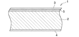
図1において、クラッド材(1)は、芯材(2)と、芯材(2)の片面を覆う第1皮材(3)と、芯材(2)の他面を覆う第2皮材(4)と、芯材(2)と第1皮材(3)との間に介在させられた中間材(5)とからなる。 In FIG. 1, the clad material (1) includes a core material (2), a first skin material (3) covering one side of the core material (2), and a second skin material covering the other surface of the core material (2). (4) and an intermediate material (5) interposed between the core material (2) and the first skin material (3).
芯材(2)は、Cu0.3〜0.5質量%、Mn0.6〜1.0質量%、Ti0.05〜0.15質量%、Zn0.1質量%以下、Fe0.3質量%以下、Si0.2質量%以下を含み、残部Alおよび不可避不純物からなるAl合金で形成されている。なお、芯材(2)は、不可避不純物としてのCr0.05質量%以下を含んでいることがある。 Core material (2) is Cu 0.3-0.5 mass%, Mn 0.6-1.0 mass%, Ti 0.05-0.15 mass%, Zn 0.1 mass% or less, Fe 0.3 mass% or less Further, Si is contained in an Al alloy containing 0.2% by mass or less and the balance being Al and inevitable impurities. The core material (2) may contain 0.05% by mass or less of Cr as an inevitable impurity.
第1皮材(3)は、Si7.9〜9.5質量%、Fe0.1〜0.3質量%、Cu0.3質量%以下を含み、残部Alおよび不可避不純物からなるAl合金で形成されている。なお、第1皮材(3)は、不可避不純物としてのMn0.05質量%以下、Zn0.05質量%以下、Cr0.05質量%以下、Ti0.05質量%以下を含んでいることがある。 The first skin material (3) includes Si 7.9 to 9.5 mass%, Fe 0.1 to 0.3 mass%, Cu 0.3 mass% or less, and is formed of an Al alloy composed of the balance Al and inevitable impurities. ing. The first skin material (3) may contain 0.05% by mass or less of Mn as an inevitable impurity, 0.05% by mass or less of Zn, 0.05% by mass or less of Cr, and 0.05% by mass or less of Ti.
第2皮材(4)は、Si4.5〜5.5質量%、Cu0.5〜0.7質量%、Fe0.8質量%以下を含み、残部Alおよび不可避不純物からなるAl合金で形成されている。なお、第2皮材(4)は、不可避不純物としてのMn0.05質量%以下、Zn0.05質量%以下、Cr0.05質量%以下、Ti0.05質量%以下を含んでいることがある。 The second skin material (4) is formed of an Al alloy including Si 4.5 to 5.5% by mass, Cu 0.5 to 0.7% by mass, Fe 0.8% by mass or less, and the balance Al and inevitable impurities. ing. The second skin material (4) may contain 0.05% by mass or less of Mn, 0.05% by mass or less of Zn, 0.05% by mass or less of Cr, and 0.05% by mass or less of Ti as inevitable impurities.
中間材(5)は、Mn0.2〜0.4質量%、Zn0.2〜0.4質量%、Fe0.4質量%以下、Cu0.05質量%以下を含み、残部Alおよび不可避不純物からなるAl合金で形成されている。なお、中間材(5)は、不可避不純物としてのSi0.25質量%以下、Cr0.05質量%以下、Ti0.05質量%以下を含んでいることがある。 The intermediate material (5) contains Mn 0.2 to 0.4 mass%, Zn 0.2 to 0.4 mass%, Fe 0.4 mass% or less, Cu 0.05 mass% or less, and the balance is Al and inevitable impurities. It is made of an Al alloy. The intermediate material (5) may contain Si 0.25% by mass or less, Cr 0.05% by mass or less, and Ti 0.05% by mass or less as inevitable impurities.
クラッド材(1)の芯材(2)、第1皮材(3)、第2皮材(4)および中間材(5)における各合金成分について説明する。
[芯材(2)]
Cuは、芯材(2)の自然電位を貴にして芯材(2)の耐食性を向上させる性質を有するが、その含有量が少なすぎると十分な耐食性が得られずに孔食が発生するおそれがあり、多すぎると芯材(2)の強度が高くなりすぎてクラッド材(1)を筒状に成形する際に成形不良が発生する。したがって、Cu含有量は0.3〜0.5質量%とすべきである。
Each alloy component in the core material (2), the first skin material (3), the second skin material (4) and the intermediate material (5) of the clad material (1) will be described.
[Core (2)]
Cu has the property of making the natural potential of the core material (2) noble and improving the corrosion resistance of the core material (2), but if its content is too small, sufficient corrosion resistance cannot be obtained and pitting corrosion occurs. If the amount is too large, the strength of the core material (2) becomes too high, and defective molding occurs when the clad material (1) is formed into a cylindrical shape. Therefore, the Cu content should be 0.3 to 0.5% by mass.
Mnは、芯材(2)の強度を増大させてヘッダタンクを製造するのに用いた際に耐圧性を向上させる性質を有するが、その含有量が少なすぎると十分な強度が得られず、多すぎると芯材(2)の強度が高くなりすぎてクラッド材(1)を筒状に成形する際に成形不良が発生する。したがって、Mn含有量は0.6〜1.0質量%とすべきである。 Mn has the property of improving pressure resistance when used to manufacture the header tank by increasing the strength of the core material (2), but if its content is too small, sufficient strength cannot be obtained, If the amount is too large, the strength of the core material (2) becomes too high, and molding defects occur when the clad material (1) is formed into a cylindrical shape. Therefore, the Mn content should be 0.6 to 1.0 mass%.
Tiは、Al合金中でTi−Al系化合物を形成して層状に分散する。Ti−Al系化合物は自然電位が貴であるため、腐食形態が層状化し、深さ方向への腐食(孔食)に進展し難くなって耐食性が向上させる性質を有する。しかしながら、その含有量が少なすぎると腐食形態の層状化効果が小さくなって耐食性が低下し、多すぎても耐食性向上効果は飽和してコストが高くなるばかりである。したがって、Ti含有量は0.05〜0.15質量%とすべきである。 Ti forms a Ti—Al-based compound in an Al alloy and is dispersed in a layered manner. Since the Ti—Al compound has a noble natural potential, the corrosion form is stratified, and the Ti—Al compound has a property of improving corrosion resistance by making it difficult to progress to corrosion (pitting corrosion) in the depth direction. However, if the content is too small, the layering effect of the corrosion form is reduced and the corrosion resistance is lowered, and if it is too much, the corrosion resistance improving effect is saturated and the cost is increased. Therefore, the Ti content should be 0.05 to 0.15 mass%.
Zn、FeおよびSiは芯材(2)中に不可避不純物として含まれるものであるが、含有量が多すぎると芯材(2)の自己耐食性が低下するので、その含有量を上述した含有量とすべきである。 Zn, Fe and Si are contained as inevitable impurities in the core material (2), but if the content is too large, the self-corrosion resistance of the core material (2) is lowered, so the content is the content described above Should be.
なお、不可避不純物として含まれるZn、Fe、Siの含有量は0の場合があってもよい。
[第1皮材(3)]
第1皮材(3)は、一般的なAl合金ろうであり、Si含有量は7.9〜9.5質量%である。
In addition, the content of Zn, Fe, and Si contained as inevitable impurities may be zero.
[First skin (3)]
The first skin material (3) is a general Al alloy braze, and the Si content is 7.9 to 9.5% by mass.
Feは、第1皮材(3)が溶融した際の流動性を向上させる性質を有するが、その含有量が少なすぎると十分なろう流れ性が得られず、多すぎると耐食性が低下する。したがって、Fe含有量は0.1〜0.3質量%とすべきである。 Fe has a property of improving fluidity when the first skin material (3) is melted, but if its content is too small, sufficient braze flowability cannot be obtained, and if it is too much, corrosion resistance is lowered. Therefore, the Fe content should be 0.1 to 0.3% by mass.
Cuは第1皮材(3)中に不可避不純物として含まれるものであるが、含有量が多すぎると中間材(5)の腐食を促進させるので、その含有量を上述した含有量とすべきである。 Cu is contained as an inevitable impurity in the first skin material (3), but if the content is too large, the corrosion of the intermediate material (5) is promoted, so the content should be the above-mentioned content It is.
なお、不可避不純物として含まれるCuの含有量は0の場合があってもよい。
[第2皮材(4)]
第2皮材(4)はろう材として働くものであり、Siは通常のAl合金ろうの場合と同様に、溶融した第2皮材(4)の流動性に影響を及ぼすが、その含有量が少なすぎると溶融した第2皮材(4)の流動性が十分ではなく、クラッド材(1)をヘッダタンクに用いた場合にヘッダタンクと熱交換管とのろう付不良が発生するおそれがある。また、Siの含有量が多くなりすぎると第2皮材(4)の流動性が良くなりすぎ、クラッド材(1)をヘッダタンクに用いた場合、ヘッダタンクにろう付される熱交換管の管路内に流入するおそれがある。したがって、Si含有量は4.5〜5.5質量%とすべきである。
In addition, the content of Cu contained as an inevitable impurity may be 0.
[Second skin (4)]
The second skin material (4) works as a brazing material, and Si affects the fluidity of the molten second skin material (4) as in the case of ordinary Al alloy brazing, but its content If there is too little, the fluidity of the melted second skin material (4) is not sufficient, and when the clad material (1) is used for the header tank, there is a risk of poor brazing between the header tank and the heat exchange pipe. is there. Also, if the Si content is too high, the fluidity of the second skin material (4) becomes too good, and when the cladding material (1) is used for the header tank, the heat exchange pipe brazed to the header tank There is a risk of flowing into the pipeline. Therefore, the Si content should be 4.5 to 5.5% by mass.
Cuは、クラッド材(1)をヘッダタンクに用いた場合に、熱交換管とのろう付部の腐食進行を抑制する性質を有するが、その含有量が少なすぎると前記ろう付部の腐食進行を十分に抑制することができず、多くなりすぎると第2皮材(4)の鋳造時に凝固割れが発生する。したがって、Cu含有量は0.5〜0.7質量%とすべきである。 Cu has a property of suppressing the progress of corrosion of the brazed portion with the heat exchange pipe when the clad material (1) is used for the header tank. However, if the content is too small, the corrosion progress of the brazed portion is suppressed. If the amount is too much, solidification cracking occurs during casting of the second skin material (4). Therefore, the Cu content should be 0.5 to 0.7% by mass.
Feは第2皮材(4)中に不可避不純物として含まれるものであるが、含有量が多すぎるとクラッド材(1)をヘッダタンクに用いた場合、熱交換管とのろう付部の耐食性が低下するので、その含有量を上述した含有量とすべきである。 Fe is included as an inevitable impurity in the second skin material (4), but if the content is too high, the corrosion resistance of the brazed part with the heat exchange pipe when the cladding material (1) is used for the header tank Therefore, the content should be the content described above.
なお、不可避不純物として含まれるFeの含有量は0の場合があってもよい。
[中間材(5)]
Mnは、中間材(5)の強度を高くして、圧延時に中間材(5)と芯材(2)および第1皮材(3)とを良好に圧着させる性質を有する。しかしながら、Mnの含有量が少なすぎると圧延時に中間材(5)と芯材(2)および第1皮材(3)とを良好に圧着させることができず、多くなりすぎると中間材(5)の強度が高くなりすぎて圧延時に中間材(5)と芯材(2)および第1皮材(3)との間に圧着不良が発生するので、Mn含有量は0.2〜0.4質量%とすべきである。
In addition, the content of Fe contained as an inevitable impurity may be 0.
[Intermediate material (5)]
Mn has the property of increasing the strength of the intermediate material (5) to favorably press the intermediate material (5), the core material (2) and the first skin material (3) during rolling. However, if the content of Mn is too small, the intermediate material (5) and the core material (2) and the first skin material (3) cannot be pressed well during rolling, and if the content is too large, the intermediate material (5 ) Becomes too strong, and poor bonding occurs between the intermediate material (5), the core material (2), and the first skin material (3) during rolling, so that the Mn content is 0.2-0. It should be 4% by weight.
Znは、中間材(5)の腐食進行速度を調整する働きをするが、その含有量が少なすぎると中間材(5)と芯材(2)との電位差が不十分になって芯材(2)に腐食が発生し、多くなりすぎると中間材(5)の腐食進行速度が速くなりすぎて中間材(5)が比較的短期間で消費する。したがって、Zn含有量は0.2〜0.4質量%とすべきである。 Zn functions to adjust the corrosion progress rate of the intermediate material (5), but if its content is too small, the potential difference between the intermediate material (5) and the core material (2) becomes insufficient, and the core material ( If corrosion occurs in 2) and increases too much, the progress of corrosion of the intermediate material (5) becomes too fast and the intermediate material (5) is consumed in a relatively short period of time. Therefore, the Zn content should be 0.2 to 0.4 mass%.
Feは中間材(5)中に不可避不純物として含まれるものであるが、含有量が多すぎると中間材(5)の耐食性が低下するので、その含有量を上述した含有量とすべきである。 Fe is included as an inevitable impurity in the intermediate material (5), but if the content is too large, the corrosion resistance of the intermediate material (5) is lowered, so the content should be the above-mentioned content .
Cuは中間材(5)中に不可避不純物として含まれるものであるが、含有量が多すぎると中間材(5)と芯材(2)との電位差が不十分になって芯材(2)に腐食が発生するので、その含有量を上述した含有量とすべきである。 Cu is contained as an inevitable impurity in the intermediate material (5), but if the content is too large, the potential difference between the intermediate material (5) and the core material (2) becomes insufficient, and the core material (2) Corrosion occurs, so the content should be the content described above.
なお、不可避不純物として含まれるFeおよびCuの含有量は0の場合があってもよい。 The content of Fe and Cu contained as inevitable impurities may be zero.
クラッド材(1)からなるパイプをヘッダタンクに用いたコンデンサの全体構成を図2および図3に示し、当該コンデンサの要部の構成を図4および図5に示す。 2 and 3 show the overall configuration of a capacitor using a pipe made of the clad material (1) as a header tank, and FIGS. 4 and 5 show the configuration of the main part of the capacitor.
図2〜図4において、コンデンサ(10)は、凝縮部(10A)および凝縮部(10A)の下方に設けられた過冷却部(10B)よりなり、幅方向を通風方向(図2および図3の紙面表裏方向)に向けるとともに長手方向を左右方向に向けた状態で上下方向に間隔をおいて配置された複数のアルミニウム押出形材製扁平状熱交換管(11)と、長手方向を上下方向に向けて配置されるとともに熱交換管(11)の左右両端部がろう付により接続された3つのアルミニウム製ヘッダタンク(12)(13)(14)と、隣り合う熱交換管(11)どうしの間および上下両端の外側に配置されて熱交換管(11)にろう付されたアルミニウム製コルゲートフィン(15)と、上下両端のコルゲートフィン(15)の外側に配置されてコルゲートフィン(15)にろう付されたアルミニウム製サイドプレート(16)とを備えている。 2 to 4, the condenser (10) is composed of a condensing part (10A) and a supercooling part (10B) provided below the condensing part (10A), and the width direction is the ventilation direction (FIGS. 2 and 3). And a plurality of extruded aluminum flat heat exchanger tubes (11) arranged in the vertical direction with the longitudinal direction oriented in the left-right direction and the longitudinal direction in the vertical direction. The three aluminum header tanks (12), (13), and (14), which are arranged facing the heat exchanger pipe (11) and connected to both left and right ends by brazing, and adjacent heat exchange pipes (11) Aluminum corrugated fin (15) brazed to the heat exchange pipe (11) between the upper and lower ends and the corrugated fin (15) disposed outside the upper and lower corrugated fins (15) And an aluminum side plate (16) brazed.
コンデンサ(10)の凝縮部(10A)および過冷却部(10B)には、それぞれ上下に連続して並んだ複数の熱交換管(11)からなる少なくとも1つ、ここでは1つの熱交換パス(P1)(P2)が設けられており、凝縮部(10A)に設けられた熱交換パス(P1)が冷媒凝縮パスとなり、過冷却部(10B)に設けられた熱交換パス(P2)が冷媒過冷却パスとなっている。各熱交換パス(P1)(P2)を構成する全ての熱交換管(11)の冷媒流れ方向が同一となっているとともに、隣り合う2つの熱交換パスの熱交換管(11)の冷媒流れ方向が異なっている。ここで、凝縮部(10A)の熱交換パス(P1)を第1熱交換パスといい、過冷却部(10B)の熱交換パス(P2)を第2熱交換パスというものとする。 The condenser (10A) and the subcooling section (10B) of the condenser (10) are each provided with at least one heat exchange path (here, one heat exchange path) (here, one heat exchange path (11)). P1) and (P2) are provided, the heat exchange path (P1) provided in the condensing part (10A) serves as a refrigerant condensing path, and the heat exchange path (P2) provided in the supercooling part (10B) serves as a refrigerant. It is a supercooling path. The refrigerant flow directions of all the heat exchange pipes (11) constituting each heat exchange path (P1) (P2) are the same, and the refrigerant flows in the heat exchange pipes (11) of two adjacent heat exchange paths. The direction is different. Here, the heat exchange path (P1) of the condensing part (10A) is referred to as a first heat exchange path, and the heat exchange path (P2) of the supercooling part (10B) is referred to as a second heat exchange path.
コンデンサ(10)の左端側には、凝縮部(10A)に設けられた第1熱交換パス(P1)の全熱交換管(11)の左端部がろう付により接続された第1ヘッダタンク(12)と、過冷却部(10B)に設けられた第2熱交換パス(P2)の全熱交換管(11)の左端部がろう付により接続された第2ヘッダタンク(13)とが、第2ヘッダタンク(13)が左右方向外側に位置するように別個に設けられている。第2ヘッダタンク(13)の下端は第1ヘッダタンク(12)の下端よりも下方に位置するとともに同上端が第1ヘッダタンク(12)の下端よりも上方に位置しており、第2ヘッダタンク(13)における第1ヘッダタンク(12)の下端よりも下方に位置する部分に第2熱交換パス(P2)の全熱交換管(11)が接続されている。すなわち、第2ヘッダタンク(13)は、第1熱交換パス(P1)と第2熱交換パス(P2)との間の高さ位置に設けられた板状のアルミニウム製仕切部材(17)により上下2つの区画(13a)(13b)に分割されており、下側区画(13b)に、過冷却部(10B)の第2熱交換パス(P2)の全熱交換管(11)の左端部がろう付により接続されている。上側区画(13a)と下側区画(13b)とは仕切部材(17)に形成された連通口(17a)を介して通じさせられている。第2ヘッダタンク(13)は、凝縮部(10A)から流入した冷媒を貯留して気相と液相とに分離するとともに、液相主体の冷媒を過冷却部(10B)に供給する機能を有している。図示は省略したが、第2ヘッダタンク(13)の上側区画(13a)内には乾燥剤が入れられている。 The left end of the condenser (10) is connected to the left end of the total heat exchange pipe (11) of the first heat exchange path (P1) provided in the condenser (10A) by brazing. 12) and a second header tank (13) in which the left end of the total heat exchange pipe (11) of the second heat exchange path (P2) provided in the supercooling section (10B) is connected by brazing. The second header tank (13) is provided separately so as to be located on the outer side in the left-right direction. The lower end of the second header tank (13) is located below the lower end of the first header tank (12), and the upper end is located above the lower end of the first header tank (12). The total heat exchange pipe (11) of the second heat exchange path (P2) is connected to a portion of the tank (13) located below the lower end of the first header tank (12). That is, the second header tank (13) is formed by a plate-like aluminum partition member (17) provided at a height position between the first heat exchange path (P1) and the second heat exchange path (P2). It is divided into two upper and lower sections (13a) and (13b). The lower section (13b) has a left end portion of the total heat exchange pipe (11) in the second heat exchange path (P2) of the supercooling section (10B). Connected by brazing. The upper section (13a) and the lower section (13b) are communicated with each other through a communication port (17a) formed in the partition member (17). The second header tank (13) has a function of storing the refrigerant flowing in from the condensing unit (10A) and separating the refrigerant into a gas phase and a liquid phase and supplying a refrigerant mainly composed of a liquid phase to the supercooling unit (10B). Have. Although not shown, a desiccant is placed in the upper section (13a) of the second header tank (13).
第1ヘッダタンク(12)内の下端寄りの部分と、第2ヘッダタンク(13)の上側区画(13a)内の下端寄りの部分とが、両ヘッダタンク(12)(13)にろう付されたアルミニウム製連通部材(18)を介して通じさせられている。 The portion near the lower end in the first header tank (12) and the portion near the lower end in the upper section (13a) of the second header tank (13) are brazed to both header tanks (12) and (13). Further, it is communicated through an aluminum communication member (18).
第1ヘッダタンク(12)は、上下両端が開口した横断面異形のアルミニウム製パイプ(19)と、パイプ(19)の上下両端にろう付されて上下両端開口を閉鎖するアルミニウム製閉鎖部材(21)とからなる。 The first header tank (12) includes an aluminum pipe (19) having a deformed cross section with both upper and lower ends opened, and an aluminum closing member (21) brazed to the upper and lower ends of the pipe (19) to close the upper and lower ends. ).
第2ヘッダタンク(13)は、上下両端が開口した横断面円形のアルミニウム製パイプ(22)と、パイプ(22)の下端にろう付されて下端開口を閉鎖する部材(23)と、パイプ(22)の上端に着脱自在に取り付けられて上端開口を閉鎖する上閉鎖部材(24)とからなる。第2ヘッダタンク(13)のパイプ(22)に、熱交換器構成部品である2つのアルミニウム製ブラケット(25)が上下方向に間隔をおいてろう付されている。 The second header tank (13) includes an aluminum pipe (22) having a circular cross section open at both upper and lower ends, a member (23) brazed to the lower end of the pipe (22) to close the lower end opening, And an upper closing member (24) which is detachably attached to the upper end of 22) and closes the upper end opening. Two aluminum brackets (25), which are heat exchanger components, are brazed to the pipe (22) of the second header tank (13) at intervals in the vertical direction.
コンデンサ(10)の右端部側には、第1および第2熱交換パス(P1)(P2)を構成する全ての熱交換管(11)の右端部が接続される第3ヘッダタンク(14)が配置されている。第3ヘッダタンク(14)は、第1熱交換パス(P1)と第2熱交換パス(P2)との間の高さ位置に設けられた板状のアルミニウム製仕切部材(26)により上下2つの区画(14a)(14b)に分割されており、上側区画(14a)に、凝縮部(10A)の第1熱交換パス(P1)の全熱交換管(11)の右端部がろう付により接続され、下側区画(14b)に、過冷却部(10B)の第2熱交換パス(P2)の全熱交換管(11)の右端部がろう付により接続されている。また、第3ヘッダタンク(14)の上側区画(14a)の高さ方向の中程に冷媒入口(27)が形成されるとともに、下側区画(14b)に冷媒出口(28)が形成されている。また、第3ヘッダタンク(14)に、冷媒入口(27)に通じるアルミニウム製冷媒入口部材(29)および冷媒出口(28)に通じるアルミニウム製冷媒出口部材(31)がろう付されている。第3ヘッダタンク(14)にも、2つのアルミニウム製ブラケット(25)が上下方向に間隔をおいてろう付されている。 A third header tank (14) connected to the right end of the condenser (10) is connected to the right ends of all the heat exchange pipes (11) constituting the first and second heat exchange paths (P1) and (P2). Is arranged. The third header tank (14) is vertically moved by a plate-like aluminum partition member (26) provided at a height position between the first heat exchange path (P1) and the second heat exchange path (P2). The right end of the total heat exchange pipe (11) of the first heat exchange path (P1) of the condenser (10A) is brazed to the upper compartment (14a) by brazing. The right end of the total heat exchange pipe (11) of the second heat exchange path (P2) of the supercooling section (10B) is connected to the lower section (14b) by brazing. A refrigerant inlet (27) is formed in the middle of the height direction of the upper section (14a) of the third header tank (14), and a refrigerant outlet (28) is formed in the lower section (14b). Yes. Further, an aluminum refrigerant inlet member (29) communicating with the refrigerant inlet (27) and an aluminum refrigerant outlet member (31) communicating with the refrigerant outlet (28) are brazed to the third header tank (14). The third header tank (14) is also brazed with two aluminum brackets (25) spaced apart in the vertical direction.
第3ヘッダタンク(14)は、上下両端が開口した第1ヘッダタンク(12)と同一横断面形状を有するアルミニウム製パイプ(32)と、パイプ(32)の上下両端にろう付されて上下両端開口を閉鎖するアルミニウム製閉鎖部材(33)とからなる。 The third header tank (14) is composed of an aluminum pipe (32) having the same cross-sectional shape as the first header tank (12) with both upper and lower ends open, and brazed to the upper and lower ends of the pipe (32). An aluminum closing member (33) for closing the opening.
コンデンサ(10)において、冷媒は、冷媒入口部材(29)および冷媒入口(27)を経て第3ヘッダタンク(14)の上側区画(14a)内に流入し、第1熱交換パス(P1)、第1ヘッダタンク(12)、連通部材(18)、第2ヘッダタンク(13)の上側区画(13a)、連通口(17a)、第2ヘッダタンク(13)の下側区画(13b)、第2熱交換パス(P2)、および第3ヘッダタンク(14)の下側区画(14b)を流れた後、冷媒出口(28)および冷媒出口部材(31)を経て流出する。 In the condenser (10), the refrigerant flows into the upper section (14a) of the third header tank (14) through the refrigerant inlet member (29) and the refrigerant inlet (27), and the first heat exchange path (P1), The first header tank (12), the communication member (18), the upper compartment (13a) of the second header tank (13), the communication port (17a), the lower compartment (13b) of the second header tank (13), the second After flowing through the two heat exchange paths (P2) and the lower section (14b) of the third header tank (14), it flows out through the refrigerant outlet (28) and the refrigerant outlet member (31).
コンデンサ(10)の第2ヘッダタンク(13)のパイプ(22)が、クラッド材(1)を用いて形成されている。図4および図5に示すように、パイプ(22)は、クラッド材(1)が、第1皮材(3)が外面側に来るように円筒状に成形されるとともに、側縁部どうしが加圧されながら突き合わされた状態で高周波抵抗溶接法により溶接されたものであり、芯材(2)と、芯材(2)の外周面を覆う第1皮材(3)と、芯材(2)の内周面を覆う第2皮材(4)と、芯材(2)と第1皮材(3)との間に介在させられた中間材(5)とからなる。パイプ(22)におけるクラッド材(1)の両側縁部どうしの溶接継手部(34)およびその近傍において、芯材(2)が外周面および内周面に露出している。パイプ(22)の外周面における芯材(2)が露出している部分を除いた部分は、第1皮材(3)で覆われており、パイプ(22)の内周面における芯材(2)が露出している部分を除いた部分は、第2皮材(4)で覆われている。パイプ(22)の溶接継手部(34)は通風方向下流側部分(図4の上側)に位置している。 The pipe (22) of the second header tank (13) of the capacitor (10) is formed using the clad material (1). As shown in FIGS. 4 and 5, the pipe (22) has a clad material (1) formed into a cylindrical shape so that the first skin material (3) is located on the outer surface side, and the side edges are separated from each other. It is welded by a high frequency resistance welding method in a state of being pressed while being pressed. The core material (2), the first skin material (3) covering the outer peripheral surface of the core material (2), and the core material ( It consists of a second skin material (4) covering the inner peripheral surface of 2) and an intermediate material (5) interposed between the core material (2) and the first skin material (3). In the pipe (22), the core material (2) is exposed on the outer peripheral surface and the inner peripheral surface in the weld joint portion (34) between both side edges of the clad material (1) and in the vicinity thereof. The portion of the outer peripheral surface of the pipe (22) excluding the portion where the core material (2) is exposed is covered with the first skin material (3), and the core material on the inner peripheral surface of the pipe (22) ( The portion excluding the portion where 2) is exposed is covered with the second skin material (4). The welded joint portion (34) of the pipe (22) is located at the downstream side portion in the ventilation direction (upper side in FIG. 4).
パイプ(22)の右側部分に通風方向に長い複数の管挿通穴(35)が上下方向に間隔をおくとともに、溶接継手部(34)から離隔するように形成されている。熱交換管(11)は、管挿通穴(33)に通されてクラッド材(1)の第1皮材(3)および第2皮材(4)によりパイプ(22)にろう付されている。ブラケット(25)は、パイプ(22)の左側における溶接継手部(34)から離隔した部分に、第1皮材(3)を用いてろう付されている。 A plurality of pipe insertion holes (35) that are long in the ventilation direction are formed in the right side portion of the pipe (22) so as to be spaced apart from each other in the vertical direction and to be separated from the weld joint (34). The heat exchange pipe (11) is passed through the pipe insertion hole (33) and brazed to the pipe (22) by the first skin material (3) and the second skin material (4) of the clad material (1). . The bracket (25) is brazed using a first skin material (3) to a portion of the left side of the pipe (22) spaced from the weld joint (34).
なお、第1ヘッダタンク(12)および第3ヘッダタンク(14)のパイプ(19)(32)は、たとえば特許文献2に記載されているように、Mn0.6〜1.5質量%、Ti0.05〜0.25質量%、Cu0.05質量%未満、Zn0.05質量%未満、Fe0.2質量%以下、Si0.45質量%以下を含み、残部Alおよび不可避不純物からなるAl合金で形成された芯材と、Si6.8〜11.0質量%、Zn0.05質量%以下を含み、残部Alおよび不可避不純物からなるAl合金で形成され、かつ芯材の片面を覆う第1皮材と、Si4.0〜6.0質量%、Cu0.5〜1.0質量%を含み、残部Alおよび不可避不純物からなるAl合金で形成され、かつ芯材の他面を覆う第2皮材とよりなるクラッド材を、第1皮材で覆われている第1面が外側に来るとともに、第2皮材で覆われている第2面が内側に来るように筒状に成形し、クラッド材の両側縁部を、第1皮材と第2皮材とが重なり合うように組み合わせ、クラッド材の第1皮材を利用してクラッド材の両側縁部どうしをろう付することにより製造される。なお、パイプ(19)(32)の製造は、コンデンサ(10)の他部品のろう付と同時に行われる。
The pipes (19) and (32) of the first header tank (12) and the third header tank (14) are, for example, as described in
上述したパイプ(22)を用いたコンデンサ(10)は、熱交換管(11)、第1ヘッダタンク(12)のパイプ(19)用の筒状に成形されたクラッド材および上下閉鎖部材(21)と、第2ヘッダタンク(13)を構成するパイプ(22)、下閉鎖部材(23)および仕切部材(17)と、第3ヘッダタンク(14)のパイプ(32)用の筒状に成形されたクラッド材、上下閉鎖部材(33)および仕切部材(26)と、連通部材(18)と、コルゲートフィン(15)と、サイドプレート(16)とを組み合わせて一括ろう付することにより製造される。 The condenser (10) using the pipe (22) described above includes a heat exchanger tube (11), a clad material formed into a cylindrical shape for the pipe (19) of the first header tank (12), and an upper and lower closing member (21). ), The pipe (22) constituting the second header tank (13), the lower closing member (23), the partition member (17), and the pipe for the pipe (32) of the third header tank (14). The clad material, the upper and lower closing member (33) and the partition member (26), the communication member (18), the corrugated fin (15), and the side plate (16) are combined and brazed together. The
次に、本発明の具体的実施例について説明する。 Next, specific examples of the present invention will be described.
表1に示すクラッド材(1)を用意した。当該クラッド材(1)の板厚は1.6mmであり、第1皮材(3)および第2皮材(4)のクラッド率は6%、中間材(5)のクラッド率は10%である。 A clad material (1) shown in Table 1 was prepared. The plate thickness of the clad material (1) is 1.6 mm, the clad rate of the first skin material (3) and the second skin material (4) is 6%, and the clad rate of the intermediate material (5) is 10%. is there.

表1のクラッド材(1)を、第1皮材(3)が外面側に来るように円筒状に成形し、側縁部どうしを加圧しながら突き合わせた状態で高周波抵抗溶接法により溶接することによりパイプ(22)をつくった。 The clad material (1) shown in Table 1 is formed into a cylindrical shape so that the first skin material (3) is on the outer surface side, and is welded by high-frequency resistance welding in a state where the side edges are pressed against each other while being pressed. Made pipe (22).
ついで、パイプ(22)と、他の部品とを組み合わせ、非腐食性フッ化物系フラックスを塗布した後、窒素ガス雰囲気とされた炉内において実体温度が598.0〜603.6℃となるように加熱し、上述した構成のコンデンサ(10)を製造した。加熱速度は、100〜500℃で35〜50℃/min、500〜580℃で14.7〜18.7℃/min、580〜600℃で3.7〜5.5℃/minであり、58℃以上での保持時間は4.0〜6.8分である。 Next, the pipe (22) is combined with other parts, and after applying a non-corrosive fluoride flux, the solid temperature becomes 598.0-603.6 ° C. in a furnace in a nitrogen gas atmosphere. The capacitor (10) having the above-described configuration was manufactured. The heating rate is 35 to 50 ° C / min at 100 to 500 ° C, 14.7 to 18.7 ° C / min at 500 to 580 ° C, 3.7 to 5.5 ° C / min at 580 to 600 ° C, The holding time at 58 ° C. or higher is 4.0 to 6.8 minutes.
こうして製造されたコンデンサ(10)について、ASTM−SWAAT試験を40日間行ったところ、試験期間経過後も洩れは発生していなかった。さらに、第2ヘッダタンク(13)の周壁の断面を観察して腐食状況を観察したところ、溶接継手部(31)およびその近傍を含んで、芯材(2)には腐食は発生していなかった。 The capacitor (10) thus manufactured was subjected to the ASTM-SWAAT test for 40 days, and no leakage occurred even after the test period. Furthermore, when the corrosion situation was observed by observing the cross section of the peripheral wall of the second header tank (13), the core material (2) was not corroded, including the welded joint (31) and its vicinity. It was.
この発明によるクラッド材は、筒状に成形して両側縁部どうしを加圧しながら突き合わせた状態で高周波抵抗溶接法により溶接してパイプを製造するのに適している。 The clad material according to the present invention is suitable for manufacturing a pipe by welding it by a high frequency resistance welding method in a state of being formed into a cylindrical shape and abutting both sides while pressing.
(1):クラッド材
(2):芯材
(3):第1皮材
(4):第2皮材
(5):中間材
(10):コンデンサ(熱交換器)
(11):熱交換管
(12)(13)(14):ヘッダタンク
(15):コルゲートフィン
(22):パイプ
(23):下閉鎖部材
(24):上閉鎖部材
(25):ブラケット(熱交換器構成部品)
(34):溶接継手部
(35):管挿通穴
(1): Clad material
(2): Core material
(3): 1st skin material
(4): Second skin material
(5): Intermediate material
(10): Capacitor (heat exchanger)
(11): Heat exchange pipe
(12) (13) (14): Header tank
(15): Corrugated fin
(22): Pipe
(23): Lower closing member
(24): Upper closing member
(25): Bracket (Heat exchanger component)
(34): Welded joint
(35): Pipe insertion hole
Claims (2)
芯材と第1皮材との間に中間材が介在させられており、
芯材が、Cu0.3〜0.5質量%、Mn0.6〜1.0質量%、Ti0.05〜0.15質量%、Zn0.1質量%以下、Fe0.3質量%以下、Si0.2質量%以下を含み、残部Alおよび不可避不純物からなるAl合金で形成され、
第1皮材が、Si7.9〜9.5質量%、Fe0.1〜0.3質量%、Cu0.3質量%以下を含み、残部Alおよび不可避不純物からなるAl合金で形成され、
第2皮材が、Si4.5〜5.5質量%、Cu0.5〜0.7質量%、Fe0.8質量%以下を含み、残部Alおよび不可避不純物からなるAl合金で形成され、
中間材が、Mn0.2〜0.4質量%、Zn0.2〜0.4質量%、Fe0.4質量%以下、Cu0.05質量%以下を含み、残部Alおよび不可避不純物からなるAl合金で形成されているクラッド材。 Having a core material, a first skin material covering one side of the core material, and a second skin material covering the other surface of the core material, the first skin material and the second skin material facing the same side, A clad material joined by a high frequency resistance welding method in a state where the side edges are abutted,
An intermediate material is interposed between the core material and the first skin material,
The core material is Cu 0.3 to 0.5 mass%, Mn 0.6 to 1.0 mass%, Ti 0.05 to 0.15 mass%, Zn 0.1 mass% or less, Fe 0.3 mass% or less, Si 0. 2% by mass or less, formed of an Al alloy consisting of the balance Al and inevitable impurities,
The first skin material is formed of an Al alloy including Si 7.9 to 9.5 mass%, Fe 0.1 to 0.3 mass%, Cu 0.3 mass% or less, and the balance Al and inevitable impurities,
The second skin material is formed of an Al alloy including Si 4.5 to 5.5 mass%, Cu 0.5 to 0.7 mass%, Fe 0.8 mass% or less, the balance Al and inevitable impurities,
The intermediate material contains Mn 0.2-0.4% by mass, Zn 0.2-0.4% by mass, Fe 0.4% by mass or less, Cu 0.05% by mass or less, and an Al alloy composed of the balance Al and inevitable impurities. Clad material that is formed.
Priority Applications (4)
| Application Number | Priority Date | Filing Date | Title |
|---|---|---|---|
| JP2015114782A JP6590536B2 (en) | 2015-06-05 | 2015-06-05 | Clad material and pipe manufacturing method |
| DE102016109718.7A DE102016109718A1 (en) | 2015-06-05 | 2016-05-25 | Composite material, process for pipe production, pipe and heat exchanger with pipe |
| US15/169,602 US20160290744A1 (en) | 2015-06-05 | 2016-05-31 | Clad material, method of manufacturing pipe, pipe, and heat exchanger using pipe |
| CN201610389019.9A CN106240081B (en) | 2015-06-05 | 2016-06-02 | Composite material, the manufacturing method of pipe fitting, pipe fitting and the heat exchanger for having used the pipe fitting |
Applications Claiming Priority (1)
| Application Number | Priority Date | Filing Date | Title |
|---|---|---|---|
| JP2015114782A JP6590536B2 (en) | 2015-06-05 | 2015-06-05 | Clad material and pipe manufacturing method |
Publications (3)
| Publication Number | Publication Date |
|---|---|
| JP2017002341A JP2017002341A (en) | 2017-01-05 |
| JP2017002341A5 JP2017002341A5 (en) | 2018-04-05 |
| JP6590536B2 true JP6590536B2 (en) | 2019-10-16 |
Family
ID=57017445
Family Applications (1)
| Application Number | Title | Priority Date | Filing Date |
|---|---|---|---|
| JP2015114782A Expired - Fee Related JP6590536B2 (en) | 2015-06-05 | 2015-06-05 | Clad material and pipe manufacturing method |
Country Status (4)
| Country | Link |
|---|---|
| US (1) | US20160290744A1 (en) |
| JP (1) | JP6590536B2 (en) |
| CN (1) | CN106240081B (en) |
| DE (1) | DE102016109718A1 (en) |
Families Citing this family (5)
| Publication number | Priority date | Publication date | Assignee | Title |
|---|---|---|---|---|
| ES2678468B1 (en) * | 2017-02-10 | 2019-05-14 | Radiadores Ordonez S A | RADIATOR FOR VEHICLE |
| JP6487973B2 (en) * | 2017-08-03 | 2019-03-20 | 株式会社Uacj | Aluminum alloy brazing sheet for heat exchanger and method for producing aluminum alloy brazing sheet for heat exchanger |
| JP2019045091A (en) * | 2017-09-05 | 2019-03-22 | 株式会社ケーヒン・サーマル・テクノロジー | Heat exchanger |
| CN108677065A (en) * | 2018-05-23 | 2018-10-19 | 大力神铝业股份有限公司 | One kind is for producing high-strength condenser composite fin material and preparation method thereof |
| CN113512672B (en) * | 2021-06-28 | 2022-07-22 | 中亿丰金益(苏州)科技有限公司 | Processing method and application of 4-series aluminum alloy and pipe |
Family Cites Families (15)
| Publication number | Priority date | Publication date | Assignee | Title |
|---|---|---|---|---|
| JPS5827335B2 (en) * | 1979-02-12 | 1983-06-08 | 住友軽金属工業株式会社 | Heart material of Al brazing sheet |
| JPS57188638A (en) * | 1981-04-10 | 1982-11-19 | Kobe Steel Ltd | Aluminum tube for heat exchanger |
| JP3345845B2 (en) * | 1993-12-22 | 2002-11-18 | 古河電気工業株式会社 | Aluminum alloy brazing sheet strip for ERW processing |
| JP3704178B2 (en) * | 1995-05-19 | 2005-10-05 | 昭和電工株式会社 | Aluminum material for brazing and drone cup type heat exchanger using the material and excellent in corrosion resistance |
| JP2003082428A (en) * | 2001-09-12 | 2003-03-19 | Furukawa Electric Co Ltd:The | Aluminum alloy brazing sheet having excellent corrosion resistance in weld zone |
| BRPI0309419B1 (en) * | 2002-04-18 | 2015-07-07 | Alcoa Inc | Multilayer brazing plate, brazing assembly and process to produce a corrosion resistant aluminum brazing plate product |
| US7255932B1 (en) * | 2002-04-18 | 2007-08-14 | Alcoa Inc. | Ultra-longlife, high formability brazing sheet |
| US20090255656A1 (en) * | 2006-03-31 | 2009-10-15 | Showda Denko K.K. | Brazed Pipe and Method of Manufacturing the Same |
| JP5054404B2 (en) | 2007-03-28 | 2012-10-24 | 株式会社神戸製鋼所 | Aluminum alloy clad material and brazing sheet for heat exchanger |
| EP2155431B1 (en) * | 2007-06-20 | 2017-08-02 | Aleris Aluminum Koblenz GmbH | Aluminium alloy brazing sheet product |
| JP5429858B2 (en) * | 2009-04-21 | 2014-02-26 | 株式会社Uacj | Aluminum alloy clad material for heat exchanger and manufacturing method thereof |
| US8986850B2 (en) * | 2011-03-16 | 2015-03-24 | Alcoa, Inc. | Multi-layer brazing sheet |
| JP5891026B2 (en) * | 2011-12-14 | 2016-03-22 | 株式会社ケーヒン・サーマル・テクノロジー | Clad material |
| JP6147470B2 (en) * | 2012-03-30 | 2017-06-14 | 株式会社神戸製鋼所 | Aluminum alloy brazing sheet for heat exchanger |
| JP2015009244A (en) | 2013-06-27 | 2015-01-19 | 株式会社ケーヒン・サーマル・テクノロジー | Clad material, method of manufacturing brazed pipe, and the brazed pipe |
-
2015
- 2015-06-05 JP JP2015114782A patent/JP6590536B2/en not_active Expired - Fee Related
-
2016
- 2016-05-25 DE DE102016109718.7A patent/DE102016109718A1/en active Pending
- 2016-05-31 US US15/169,602 patent/US20160290744A1/en not_active Abandoned
- 2016-06-02 CN CN201610389019.9A patent/CN106240081B/en active Active
Also Published As
| Publication number | Publication date |
|---|---|
| CN106240081B (en) | 2019-06-14 |
| DE102016109718A1 (en) | 2016-12-08 |
| JP2017002341A (en) | 2017-01-05 |
| CN106240081A (en) | 2016-12-21 |
| US20160290744A1 (en) | 2016-10-06 |
Similar Documents
| Publication | Publication Date | Title |
|---|---|---|
| JP6590536B2 (en) | Clad material and pipe manufacturing method | |
| JP4698416B2 (en) | Delon cup type heat exchanger manufacturing method, aluminum clad plate material, and drone cup type heat exchanger | |
| KR101589918B1 (en) | Heat transfer tube and method for producing same | |
| JP2017002341A5 (en) | ||
| US9744610B2 (en) | Clad material, method of manufacturing brazed pipe, and brazed pipe | |
| JP6564620B2 (en) | Heat exchanger and manufacturing method thereof | |
| JP5891026B2 (en) | Clad material | |
| CN102667394A (en) | Soldered aluminum heat exchanger | |
| JP2016223725A5 (en) | ||
| JP2010197002A (en) | Tube for plate bending-type aluminum heat exchanger, aluminum heat exchanger, and method of manufacturing tube for plate bending-type aluminum heat exchanger | |
| JP4236183B2 (en) | Aluminum alloy clad material for automotive heat exchanger | |
| CN106103761B (en) | Electric seam welding aluminium alloy brazing sheet | |
| JP5977640B2 (en) | Aluminum pipe joint | |
| JP4236185B2 (en) | Aluminum alloy clad material for automotive heat exchanger | |
| EP3222739A1 (en) | Aluminum alloy cladding material for heat exchanger | |
| JP2019070499A (en) | Method of manufacturing heat exchanger | |
| JP5599131B2 (en) | Aluminum alloy brazing material and method for producing aluminum alloy brazing sheet | |
| JP4236184B2 (en) | Aluminum alloy clad material for automotive heat exchanger | |
| JP4236187B2 (en) | Aluminum alloy clad material for automotive heat exchanger | |
| JP2007182602A (en) | Aluminum brazing alloy with suppressed erosion during brazing, brazing sheet using the same, header pipe for heat exchanger, and heat exchanger | |
| JPH11315337A (en) | Aluminum alloy brazing sheet for formation of brazed tube, and brazed tube | |
| US20080277455A1 (en) | Method for joining components made of a high-strength aluminum material and heat exchanger assembled according to the method | |
| JP4861905B2 (en) | Aluminum alloy brazing material and aluminum alloy brazing sheet | |
| JP2010240696A (en) | Joining method of tube material, and heat exchanger formed by joining tube material joined by joining method and fin material | |
| JP4440550B2 (en) | Aluminum heat exchanger |
Legal Events
| Date | Code | Title | Description |
|---|---|---|---|
| A521 | Request for written amendment filed |
Free format text: JAPANESE INTERMEDIATE CODE: A523 Effective date: 20180222 |
|
| A621 | Written request for application examination |
Free format text: JAPANESE INTERMEDIATE CODE: A621 Effective date: 20180222 |
|
| A977 | Report on retrieval |
Free format text: JAPANESE INTERMEDIATE CODE: A971007 Effective date: 20190116 |
|
| A131 | Notification of reasons for refusal |
Free format text: JAPANESE INTERMEDIATE CODE: A131 Effective date: 20190205 |
|
| A521 | Request for written amendment filed |
Free format text: JAPANESE INTERMEDIATE CODE: A523 Effective date: 20190313 |
|
| TRDD | Decision of grant or rejection written | ||
| A01 | Written decision to grant a patent or to grant a registration (utility model) |
Free format text: JAPANESE INTERMEDIATE CODE: A01 Effective date: 20190820 |
|
| A61 | First payment of annual fees (during grant procedure) |
Free format text: JAPANESE INTERMEDIATE CODE: A61 Effective date: 20190917 |
|
| R150 | Certificate of patent or registration of utility model |
Ref document number: 6590536 Country of ref document: JP Free format text: JAPANESE INTERMEDIATE CODE: R150 |
|
| S533 | Written request for registration of change of name |
Free format text: JAPANESE INTERMEDIATE CODE: R313533 |
|
| R350 | Written notification of registration of transfer |
Free format text: JAPANESE INTERMEDIATE CODE: R350 |
|
| S111 | Request for change of ownership or part of ownership |
Free format text: JAPANESE INTERMEDIATE CODE: R313113 |
|
| R360 | Written notification for declining of transfer of rights |
Free format text: JAPANESE INTERMEDIATE CODE: R360 |
|
| R360 | Written notification for declining of transfer of rights |
Free format text: JAPANESE INTERMEDIATE CODE: R360 |
|
| R371 | Transfer withdrawn |
Free format text: JAPANESE INTERMEDIATE CODE: R371 |
|
| S111 | Request for change of ownership or part of ownership |
Free format text: JAPANESE INTERMEDIATE CODE: R313113 |
|
| R350 | Written notification of registration of transfer |
Free format text: JAPANESE INTERMEDIATE CODE: R350 |
|
| LAPS | Cancellation because of no payment of annual fees |