JP6564620B2 - Heat exchanger and manufacturing method thereof - Google Patents
Heat exchanger and manufacturing method thereof Download PDFInfo
- Publication number
- JP6564620B2 JP6564620B2 JP2015112080A JP2015112080A JP6564620B2 JP 6564620 B2 JP6564620 B2 JP 6564620B2 JP 2015112080 A JP2015112080 A JP 2015112080A JP 2015112080 A JP2015112080 A JP 2015112080A JP 6564620 B2 JP6564620 B2 JP 6564620B2
- Authority
- JP
- Japan
- Prior art keywords
- mass
- heat exchange
- brazing
- core material
- tube
- Prior art date
- Legal status (The legal status is an assumption and is not a legal conclusion. Google has not performed a legal analysis and makes no representation as to the accuracy of the status listed.)
- Expired - Fee Related
Links
Images


Classifications
-
- F—MECHANICAL ENGINEERING; LIGHTING; HEATING; WEAPONS; BLASTING
- F28—HEAT EXCHANGE IN GENERAL
- F28F—DETAILS OF HEAT-EXCHANGE AND HEAT-TRANSFER APPARATUS, OF GENERAL APPLICATION
- F28F21/00—Constructions of heat-exchange apparatus characterised by the selection of particular materials
- F28F21/08—Constructions of heat-exchange apparatus characterised by the selection of particular materials of metal
- F28F21/081—Heat exchange elements made from metals or metal alloys
- F28F21/084—Heat exchange elements made from metals or metal alloys from aluminium or aluminium alloys
-
- B—PERFORMING OPERATIONS; TRANSPORTING
- B23—MACHINE TOOLS; METAL-WORKING NOT OTHERWISE PROVIDED FOR
- B23P—METAL-WORKING NOT OTHERWISE PROVIDED FOR; COMBINED OPERATIONS; UNIVERSAL MACHINE TOOLS
- B23P15/00—Making specific metal objects by operations not covered by a single other subclass or a group in this subclass
- B23P15/26—Making specific metal objects by operations not covered by a single other subclass or a group in this subclass heat exchangers or the like
-
- B—PERFORMING OPERATIONS; TRANSPORTING
- B23—MACHINE TOOLS; METAL-WORKING NOT OTHERWISE PROVIDED FOR
- B23K—SOLDERING OR UNSOLDERING; WELDING; CLADDING OR PLATING BY SOLDERING OR WELDING; CUTTING BY APPLYING HEAT LOCALLY, e.g. FLAME CUTTING; WORKING BY LASER BEAM
- B23K1/00—Soldering, e.g. brazing, or unsoldering
- B23K1/0008—Soldering, e.g. brazing, or unsoldering specially adapted for particular articles or work
- B23K1/0012—Brazing heat exchangers
-
- B—PERFORMING OPERATIONS; TRANSPORTING
- B32—LAYERED PRODUCTS
- B32B—LAYERED PRODUCTS, i.e. PRODUCTS BUILT-UP OF STRATA OF FLAT OR NON-FLAT, e.g. CELLULAR OR HONEYCOMB, FORM
- B32B15/00—Layered products comprising a layer of metal
- B32B15/01—Layered products comprising a layer of metal all layers being exclusively metallic
- B32B15/016—Layered products comprising a layer of metal all layers being exclusively metallic all layers being formed of aluminium or aluminium alloys
-
- B—PERFORMING OPERATIONS; TRANSPORTING
- B32—LAYERED PRODUCTS
- B32B—LAYERED PRODUCTS, i.e. PRODUCTS BUILT-UP OF STRATA OF FLAT OR NON-FLAT, e.g. CELLULAR OR HONEYCOMB, FORM
- B32B15/00—Layered products comprising a layer of metal
- B32B15/01—Layered products comprising a layer of metal all layers being exclusively metallic
- B32B15/017—Layered products comprising a layer of metal all layers being exclusively metallic one layer being formed of aluminium or an aluminium alloy, another layer being formed of an alloy based on a non ferrous metal other than aluminium
-
- C—CHEMISTRY; METALLURGY
- C22—METALLURGY; FERROUS OR NON-FERROUS ALLOYS; TREATMENT OF ALLOYS OR NON-FERROUS METALS
- C22C—ALLOYS
- C22C21/00—Alloys based on aluminium
-
- C—CHEMISTRY; METALLURGY
- C22—METALLURGY; FERROUS OR NON-FERROUS ALLOYS; TREATMENT OF ALLOYS OR NON-FERROUS METALS
- C22C—ALLOYS
- C22C21/00—Alloys based on aluminium
- C22C21/02—Alloys based on aluminium with silicon as the next major constituent
-
- F—MECHANICAL ENGINEERING; LIGHTING; HEATING; WEAPONS; BLASTING
- F25—REFRIGERATION OR COOLING; COMBINED HEATING AND REFRIGERATION SYSTEMS; HEAT PUMP SYSTEMS; MANUFACTURE OR STORAGE OF ICE; LIQUEFACTION SOLIDIFICATION OF GASES
- F25B—REFRIGERATION MACHINES, PLANTS OR SYSTEMS; COMBINED HEATING AND REFRIGERATION SYSTEMS; HEAT PUMP SYSTEMS
- F25B39/00—Evaporators; Condensers
- F25B39/04—Condensers
-
- F—MECHANICAL ENGINEERING; LIGHTING; HEATING; WEAPONS; BLASTING
- F28—HEAT EXCHANGE IN GENERAL
- F28D—HEAT-EXCHANGE APPARATUS, NOT PROVIDED FOR IN ANOTHER SUBCLASS, IN WHICH THE HEAT-EXCHANGE MEDIA DO NOT COME INTO DIRECT CONTACT
- F28D1/00—Heat-exchange apparatus having stationary conduit assemblies for one heat-exchange medium only, the media being in contact with different sides of the conduit wall, in which the other heat-exchange medium is a large body of fluid, e.g. domestic or motor car radiators
- F28D1/02—Heat-exchange apparatus having stationary conduit assemblies for one heat-exchange medium only, the media being in contact with different sides of the conduit wall, in which the other heat-exchange medium is a large body of fluid, e.g. domestic or motor car radiators with heat-exchange conduits immersed in the body of fluid
- F28D1/04—Heat-exchange apparatus having stationary conduit assemblies for one heat-exchange medium only, the media being in contact with different sides of the conduit wall, in which the other heat-exchange medium is a large body of fluid, e.g. domestic or motor car radiators with heat-exchange conduits immersed in the body of fluid with tubular conduits
- F28D1/053—Heat-exchange apparatus having stationary conduit assemblies for one heat-exchange medium only, the media being in contact with different sides of the conduit wall, in which the other heat-exchange medium is a large body of fluid, e.g. domestic or motor car radiators with heat-exchange conduits immersed in the body of fluid with tubular conduits the conduits being straight
- F28D1/0535—Heat-exchange apparatus having stationary conduit assemblies for one heat-exchange medium only, the media being in contact with different sides of the conduit wall, in which the other heat-exchange medium is a large body of fluid, e.g. domestic or motor car radiators with heat-exchange conduits immersed in the body of fluid with tubular conduits the conduits being straight the conduits having a non-circular cross-section
- F28D1/05366—Assemblies of conduits connected to common headers, e.g. core type radiators
- F28D1/05391—Assemblies of conduits connected to common headers, e.g. core type radiators with multiple rows of conduits or with multi-channel conduits combined with a particular flow pattern, e.g. multi-row multi-stage radiators
-
- F—MECHANICAL ENGINEERING; LIGHTING; HEATING; WEAPONS; BLASTING
- F28—HEAT EXCHANGE IN GENERAL
- F28F—DETAILS OF HEAT-EXCHANGE AND HEAT-TRANSFER APPARATUS, OF GENERAL APPLICATION
- F28F1/00—Tubular elements; Assemblies of tubular elements
- F28F1/02—Tubular elements of cross-section which is non-circular
- F28F1/022—Tubular elements of cross-section which is non-circular with multiple channels
-
- F—MECHANICAL ENGINEERING; LIGHTING; HEATING; WEAPONS; BLASTING
- F28—HEAT EXCHANGE IN GENERAL
- F28F—DETAILS OF HEAT-EXCHANGE AND HEAT-TRANSFER APPARATUS, OF GENERAL APPLICATION
- F28F1/00—Tubular elements; Assemblies of tubular elements
- F28F1/10—Tubular elements and assemblies thereof with means for increasing heat-transfer area, e.g. with fins, with projections, with recesses
- F28F1/12—Tubular elements and assemblies thereof with means for increasing heat-transfer area, e.g. with fins, with projections, with recesses the means being only outside the tubular element
- F28F1/126—Tubular elements and assemblies thereof with means for increasing heat-transfer area, e.g. with fins, with projections, with recesses the means being only outside the tubular element consisting of zig-zag shaped fins
- F28F1/128—Fins with openings, e.g. louvered fins
-
- F—MECHANICAL ENGINEERING; LIGHTING; HEATING; WEAPONS; BLASTING
- F28—HEAT EXCHANGE IN GENERAL
- F28F—DETAILS OF HEAT-EXCHANGE AND HEAT-TRANSFER APPARATUS, OF GENERAL APPLICATION
- F28F21/00—Constructions of heat-exchange apparatus characterised by the selection of particular materials
- F28F21/08—Constructions of heat-exchange apparatus characterised by the selection of particular materials of metal
- F28F21/089—Coatings, claddings or bonding layers made from metals or metal alloys
-
- F—MECHANICAL ENGINEERING; LIGHTING; HEATING; WEAPONS; BLASTING
- F25—REFRIGERATION OR COOLING; COMBINED HEATING AND REFRIGERATION SYSTEMS; HEAT PUMP SYSTEMS; MANUFACTURE OR STORAGE OF ICE; LIQUEFACTION SOLIDIFICATION OF GASES
- F25B—REFRIGERATION MACHINES, PLANTS OR SYSTEMS; COMBINED HEATING AND REFRIGERATION SYSTEMS; HEAT PUMP SYSTEMS
- F25B2339/00—Details of evaporators; Details of condensers
- F25B2339/04—Details of condensers
- F25B2339/045—Condensers made by assembling a tube on a plate-like element or between plate-like elements
-
- F—MECHANICAL ENGINEERING; LIGHTING; HEATING; WEAPONS; BLASTING
- F28—HEAT EXCHANGE IN GENERAL
- F28D—HEAT-EXCHANGE APPARATUS, NOT PROVIDED FOR IN ANOTHER SUBCLASS, IN WHICH THE HEAT-EXCHANGE MEDIA DO NOT COME INTO DIRECT CONTACT
- F28D21/00—Heat-exchange apparatus not covered by any of the groups F28D1/00 - F28D20/00
- F28D2021/0019—Other heat exchangers for particular applications; Heat exchange systems not otherwise provided for
- F28D2021/008—Other heat exchangers for particular applications; Heat exchange systems not otherwise provided for for vehicles
- F28D2021/0084—Condensers
-
- F—MECHANICAL ENGINEERING; LIGHTING; HEATING; WEAPONS; BLASTING
- F28—HEAT EXCHANGE IN GENERAL
- F28F—DETAILS OF HEAT-EXCHANGE AND HEAT-TRANSFER APPARATUS, OF GENERAL APPLICATION
- F28F2275/00—Fastening; Joining
- F28F2275/04—Fastening; Joining by brazing
Description
この発明は熱交換器およびその製造方法に関し、さらに詳しくいえば、たとえば自動車などの車両に搭載されるカーエアコン用コンデンサとして用いられる熱交換器およびその製造方法に関する。 The present invention relates to a heat exchanger and a manufacturing method thereof, and more specifically to a heat exchanger used as a car air conditioner capacitor mounted on a vehicle such as an automobile and a manufacturing method thereof.
この明細書および特許請求の範囲において、「アルミニウム」という用語には、純アルミニウムの他にアルミニウム合金を含むものとする。また、元素記号で表現された材料は純材料を意味し、「Al合金」という用語はアルミニウム合金を意味するものとする。 In this specification and claims, the term “aluminum” includes aluminum alloys in addition to pure aluminum. Further, the material represented by the element symbol means a pure material, and the term “Al alloy” means an aluminum alloy.
また、この明細書において、「自然電位」とは、5%NaCl、pH3(酸性)の水溶液中における標準電極としての飽和カロメル電極(S.C.E)に対する材料が持つ電極電位を意味するものである。 In this specification, “natural potential” means an electrode potential of a material with respect to a saturated calomel electrode (SCE) as a standard electrode in an aqueous solution of 5% NaCl, pH 3 (acidic). It is.
カーエアコン用コンデンサに用いられる熱交換器として、長手方向を同方向に向けるとともに幅方向を通風方向に向けた状態で、厚み方向に間隔をおいて配置された複数のアルミニウム押出形材製扁平状熱交換管と、長手方向を熱交換管の並び方向に向けた状態で熱交換管の長手方向両端側に配置され、かつ熱交換管の両端部が接続されたヘッダタンクと、隣り合う熱交換管どうしの間および両端の熱交換管の外側に配置されて熱交換管にろう付されたアルミニウム製コルゲート状フィンと、両端のフィンの外側に配置されてフィンにろう付されたアルミニウム製サイドプレートとを備えており、ヘッダタンクが、両面にろう材層を有するアルミニウムブレージングシートを筒状に成形して両側縁部どうしの突き合わせ部をろう付することにより形成され、かつ両端が開口した筒状のアルミニウム製タンク本体と、タンク本体の両端にろう付されてその両端開口を閉鎖するアルミニウム製閉鎖部材とからなり、タンク本体に、長手方向を通風方向に向けた長穴からなる複数の管挿入穴が、タンク本体の長手方向に間隔をおいて形成され、熱交換管の端部が、管挿入穴内に挿入されてタンク本体にろう付されているものが広く知られている。 As a heat exchanger used in a condenser for a car air conditioner, a flat shape made of a plurality of extruded aluminum parts arranged at intervals in the thickness direction with the longitudinal direction directed in the same direction and the width direction directed in the ventilation direction Adjacent heat exchange with a heat exchange pipe and a header tank arranged at both ends in the longitudinal direction of the heat exchange pipe with the longitudinal direction directed in the direction of arrangement of the heat exchange pipe and connected to both ends of the heat exchange pipe Aluminum corrugated fins placed between the tubes and outside the heat exchange tubes at both ends and brazed to the heat exchange tubes, and aluminum side plates placed outside the fins at both ends and brazed to the fins The header tank is formed of an aluminum brazing sheet having a brazing filler metal layer on both sides into a cylindrical shape and brazed the butted portions of both side edges. A cylindrical aluminum tank body that is formed at both ends and an aluminum closing member that is brazed to both ends of the tank body to close the opening at both ends. A plurality of tube insertion holes consisting of long holes directed toward the tank are formed at intervals in the longitudinal direction of the tank body, and the end of the heat exchange tube is inserted into the tube insertion hole and brazed to the tank body Things are widely known.
上述した熱交換器の製造方法として、本出願人は、先に、たとえば Cu0.3〜0.6質量%、Mn0.1〜0.4質量%を含み、残部Alおよび不可避不純物よりなるAl合金からなる押出形材製管材本体、および管材本体の外周面全体を覆うように形成された2〜8g/m2のZn溶射層とによって構成されている熱交換器用管材と、Zn2.3〜2.7質量%、Mn1.1〜1.3質量%を含み、残部Alおよび不可避不純物よりなるAl合金で形成された芯材と、Si7.9〜9.5質量%、Cu0.1〜0.3質量%、Mn0.1〜0.3質量%を含み、残部Alおよび不可避不純物よりなるAl合金で形成され、かつ芯材の両面を覆うろう材とからなるブレージングシートによって形成されている熱交換器用フィン材とをろう付することを含む方法を提案した(特許文献1参照)。 As a manufacturing method of the heat exchanger described above, the present applicant has previously described an Al alloy containing, for example, Cu 0.3 to 0.6 mass%, Mn 0.1 to 0.4 mass%, and the balance Al and inevitable impurities. A tubular body for heat exchanger composed of a extruded tube member main body, and a 2-8 g / m 2 Zn sprayed layer formed so as to cover the entire outer peripheral surface of the tubular body, and Zn 2.3-2 0.7% by mass, Mn 1.1 to 1.3% by mass, a core material made of an Al alloy composed of the balance Al and inevitable impurities, Si 7.9 to 9.5% by mass, Cu 0.1 to 0.3%. 3% by mass, Mn 0.1 to 0.3% by mass, heat exchange formed by a brazing sheet formed of an Al alloy composed of the balance Al and inevitable impurities, and a brazing material covering both sides of the core material Brazing dexterous fin material It proposed a method comprising Rukoto (see Patent Document 1).
しかしながら、特許文献1記載の方法により製造された熱交換器の熱交換管はアルミニウム押出形材製であるので、その管壁の薄肉化には限界があり、熱交換管、ひいては熱交換器全体のさらなる軽量化を図ることができない。 However, since the heat exchange tube of the heat exchanger manufactured by the method described in Patent Document 1 is made of an extruded aluminum material, there is a limit to reducing the wall thickness of the tube, and the heat exchange tube, and thus the entire heat exchanger, is limited. Cannot be further reduced in weight.
そこで、特許文献1記載の方法により軽量化を図りうる熱交換器として、本出願人は、先に、たとえば熱交換管が、芯材と、芯材の両面を覆うろう材とからなる熱交換素材を曲げて扁平中空状体を得るとともに、当該扁平中空状体の継ぎ目部分をろう付することによりつくられたものが用いられている熱交換器を提案した(特許文献2参照)。 Therefore, as a heat exchanger that can be reduced in weight by the method described in Patent Document 1, the present applicant firstly exchanges heat, for example, in which a heat exchange tube includes a core material and a brazing material that covers both surfaces of the core material. A heat exchanger has been proposed in which a flat hollow body is obtained by bending a material, and a product produced by brazing the joint portion of the flat hollow body is used (see Patent Document 2).
しかしながら、特許文献2記載の熱交換器において、熱交換管の薄肉化を図った上で要求される耐食性を確保するには、熱交換管の管壁に発生する腐食の深さを浅くする必要がある。
However, in the heat exchanger described in
この発明の目的は、上記問題を解決し、熱交換管の薄肉化を図った上で要求される耐食性を確保しうる熱交換器およびその製造方法を提供することにある。 An object of the present invention is to provide a heat exchanger capable of securing the corrosion resistance required after solving the above problems and reducing the thickness of a heat exchange tube, and a method for manufacturing the same.
本発明は、上記目的を達成するために以下の態様からなる。 In order to achieve the above object, the present invention comprises the following aspects.
1)長手方向を同方向に向けるとともに幅方向を通風方向に向けた状態で、厚み方向に間隔をおいて配置された複数の扁平状熱交換管と、隣り合う熱交換管間に配置されて熱交換管にろう付されたフィンとを有する熱交換器において、
熱交換管が、Cu0.3〜0.5質量%、Mn0.6〜1.0質量%、Ti0.05〜0.15質量%を含み、残部Alおよび不可避不純物からなるとともに、不可避不純物としてのZnの含有量が0であるAl合金で形成された芯材と、Si7.0〜8.0質量%、Zn2.0〜3.0質量%を含み、残部Alおよび不可避不純物からなるとともに、不可避不純物としてのCuの含有量が0であるAl合金で形成され、かつ芯材の片面を、クラッド率が16〜22%となるように覆う第1ろう材と、Si9.5〜10.5質量%を含み、残部Alおよび不可避不純物からなるAl合金で形成され、かつ芯材の他面を覆う第2ろう材とからなる肉厚170μm以上のブレージングシートが、第1ろう材が外側に来るように曲げられて扁平中空状の熱交換管素材とされるとともに、熱交換管素材の必要部分をろう付することによりつくられており、フィンがアルミニウムベア材からなり、
熱交換管の管壁が、前記芯材からなる芯材層と、前記第1ろう材からなりかつ芯材層の外面を覆う第1ろう材層と、前記第2ろう材からなりかつ芯材層の内面を覆う第2ろう材層とよりなり、芯材層の外面表層部にZn拡散層が形成されるとともに、当該Zn拡散層の最深部分が熱交換管の管壁の最外面から70〜100μmの深さ位置にあり、熱交換管の管壁の最外面のZn濃度が0.55質量%以上であり、前記Zn拡散層に、芯材層と第1ろう材層との境界部分の自然電位よりも41mV以上高くなった自然電位を有する高電位部分が存在している熱交換器。
1) In a state where the longitudinal direction is the same direction and the width direction is directed to the ventilation direction, it is arranged between a plurality of flat heat exchange tubes arranged at intervals in the thickness direction and adjacent heat exchange tubes. In a heat exchanger having fins brazed to a heat exchange tube,
The heat exchange tube contains 0.3 to 0.5% by mass of Cu, 0.6 to 1.0% by mass of Mn, 0.05 to 0.15% by mass of Ti, and is composed of the balance Al and unavoidable impurities . It contains a core material made of an Al alloy with a Zn content of 0 , Si 7.0-8.0 mass%, Zn 2.0-3.0 mass%, and consists of the balance Al and inevitable impurities , and is unavoidable A first brazing material which is formed of an Al alloy having a Cu content of 0 as an impurity and covers one side of the core material so that the cladding rate is 16 to 22%; and Si 9.5 to 10.5 mass The brazing sheet having a thickness of 170 μm or more formed of an Al alloy composed of the remaining Al and inevitable impurities and including the second brazing material covering the other surface of the core so that the first brazing material comes outside Bend into flat hollow Together are of a heat exchanger tube material, a necessary portion of the heat exchange tube material is made by brazing, the fin is made of aluminum bare material,
The tube wall of the heat exchange tube is made of the core material layer made of the core material, the first brazing material layer made of the first brazing material and covering the outer surface of the core material layer, and the core material made of the second brazing material. The Zn diffusion layer is formed on the outer surface layer portion of the core material layer, and the deepest portion of the Zn diffusion layer is 70 from the outermost surface of the tube wall of the heat exchange tube. The Zn concentration on the outermost surface of the tube wall of the heat exchange tube is 0.55% by mass or more at a depth position of ˜100 μm, and the Zn diffusion layer has a boundary portion between the core material layer and the first brazing material layer A heat exchanger having a high potential portion having a natural potential that is 41 mV or more higher than the natural potential.
2)フィンが、Mn1.0〜1.5質量%、Zn1.2〜1.8質量%を含み、残部Alおよび不可避不純物からなるAl合金で形成されている上記1)記載の熱交換器。 2) The heat exchanger as described in 1) above, wherein the fin comprises Mn 1.0 to 1.5 mass%, Zn 1.2 to 1.8 mass%, and is formed of an Al alloy composed of the balance Al and inevitable impurities.
3)上記1)記載の熱交換器を製造する方法であって、
Cu0.3〜0.5質量%、Mn0.6〜1.0質量%、Ti0.05〜0.15質量%を含み、残部Alおよび不可避不純物からなるとともに、不可避不純物としてのZnの含有量が0であるAl合金で形成された芯材と、Si7.0〜8.0質量%、Zn2.0〜3.0質量%を含み、残部Alおよび不可避不純物からなるとともに、不可避不純物としてのCuの含有量が0であるAl合金で形成され、かつ芯材の片面を、クラッド率が16〜22%となるように覆う第1ろう材と、Si9.5〜10.5質量%を含み、残部Alおよび不可避不純物からなるAl合金で形成され、かつ芯材の他面を覆う第2ろう材とからなる肉厚170μm以上のブレージングシートを曲げて扁平中空状の熱交換管素材をつくるとともに、熱交換管素材の必要部分をろう付して熱交換管を形成すること、ならびに熱交換管の形成と同時に形成された熱交換管とアルミニウムベア材製フィンとをろう付することを含む熱交換器の製造方法。
3) A method for producing the heat exchanger according to 1) above,
Cu 0.3-0.5% by mass, Mn 0.6-1.0% by mass, Ti 0.05-0.15% by mass, comprising the balance Al and inevitable impurities, and the content of Zn as an inevitable impurity is A core material formed of an Al alloy that is 0 , Si 7.0 to 8.0 mass%, Zn 2.0 to 3.0 mass%, and the balance consisting of Al and inevitable impurities, and Cu as an inevitable impurity A first brazing material that is formed of an Al alloy having a content of 0 and covers one side of the core material so that the cladding rate is 16 to 22%; and Si 9.5 to 10.5% by mass, and the balance A flat hollow heat exchange tube material is formed by bending a brazing sheet having a thickness of 170 μm or more formed of an Al alloy composed of Al and inevitable impurities and comprising a second brazing material covering the other surface of the core material. Exchange tube material That the necessary portions are brazed to form a heat exchange tubes, and a manufacturing method of a heat exchanger comprising a simultaneously formed heat exchange tubes and an aluminum bare material made fin and forming a heat exchange tube to brazing.
4)フィンが、Mn1.0〜1.5質量%、Zn1.2〜1.8質量%を含み、残部Alおよび不可避不純物からなるAl合金で形成されている上記3)記載の熱交換器の製造方法。 4) The heat exchanger according to 3) above , wherein the fin contains Mn 1.0 to 1.5 mass%, Zn 1.2 to 1.8 mass%, and is formed of an Al alloy composed of the balance Al and inevitable impurities. Production method.
上記1)および2)の熱交換器によれば、熱交換管の管壁が、前記芯材からなる芯材層と、前記第1ろう材からなりかつ芯材層の外面を覆う第1ろう材層と、前記第2ろう材からなりかつ芯材層の内面を覆う第2ろう材層とよりなり、芯材層の外面表層部にZn拡散層が形成されるとともに、当該Zn拡散層の最深部分が熱交換管の管壁の最外面から70〜100μmの深さ位置にあり、熱交換管の管壁の最外面のZn濃度が0.55質量%以上であり、前記Zn拡散層に、芯材層と第1ろう材層との境界部分の自然電位よりも41mV以上高くなった自然電位を有する高電位部分が存在しているので、熱交換管の管壁の外面からの腐食が前記高電位部分で止まることになる。したがって、腐食深さを浅くすることができ、熱交換管の耐食性が向上する。その結果、熱交換管の管壁の薄肉化を図ることが可能となり、熱交換管の軽量化、ひいては熱交換器の軽量化を図ることができる。 According to the heat exchangers of 1) and 2) above, the tube wall of the heat exchange tube is made of the core material layer made of the core material, and the first brazing material made of the first brazing material and covering the outer surface of the core material layer. And a second brazing material layer made of the second brazing material and covering the inner surface of the core material layer. A Zn diffusion layer is formed on the outer surface of the core material layer, and the Zn diffusion layer The deepest portion is at a depth of 70 to 100 μm from the outermost surface of the tube wall of the heat exchange tube, the Zn concentration on the outermost surface of the tube wall of the heat exchange tube is 0.55 mass% or more, and the Zn diffusion layer Since there is a high potential portion having a natural potential that is 41 mV or more higher than the natural potential at the boundary portion between the core material layer and the first brazing filler metal layer, corrosion from the outer surface of the tube wall of the heat exchange tube occurs. It stops at the high potential portion. Therefore, the corrosion depth can be reduced, and the corrosion resistance of the heat exchange tube is improved. As a result, it is possible to reduce the thickness of the tube wall of the heat exchange tube, and thus it is possible to reduce the weight of the heat exchange tube and hence the heat exchanger.
上記2)の熱交換器によれば、フィンにベア材を使用することにより、ブレージングシートを使用した場合に比べて耐食性が向上する。 According to the heat exchanger of 2) above, the use of the bare material for the fins improves the corrosion resistance compared to the case where the brazing sheet is used.
上記3)および4)の製造方法によれば、上記1)の熱交換器を比較的簡単に製造することができる。 According to the production methods of 3) and 4) , the heat exchanger of 1) can be produced relatively easily.
上記4)の製造方法によれば、フィンにベア材を使用することにより、ブレージングシートを使用した場合に比べて耐食性が向上する。 According to the manufacturing method of 4) above , the use of a bare material for the fin improves the corrosion resistance as compared with the case where a brazing sheet is used.
以下、この発明の実施形態を、図面を参照して説明する。この実施形態は、この発明の熱交換器をカーエアコン用コンデンサに適用したものである。 Embodiments of the present invention will be described below with reference to the drawings. In this embodiment, the heat exchanger of the present invention is applied to a condenser for a car air conditioner.
図1はこの発明の熱交換器を適用したカーエアコン用コンデンサの全体構成を示し、図2および図3はその要部の構成を示す。 FIG. 1 shows the overall configuration of a car air conditioner capacitor to which the heat exchanger of the present invention is applied, and FIGS. 2 and 3 show the configuration of the main part thereof.
なお、以下の説明において、図1の上下、左右を上下、左右というものとする。 In the following description, the upper and lower sides and the left and right sides in FIG.
図1において、カーエアコン用のコンデンサ(1)は、長手方向を左右方向に向に向けるとともに幅方向を通風方向に向けた状態で、上下方向(熱交換管(2)の厚み方向)に間隔をおいて配置された複数のアルミニウム製扁平状熱交換管(2)と、隣り合う熱交換管(2)どうしの間、および上下両端の熱交換管(2)の外側に配置されて熱交換管(2)にろう付されたアルミニウムベア材製コルゲートフィン(3)と、長手方向を上下方向(熱交換管(2)の並び方向)に向けた状態で左右方向に間隔をおいて配置され、かつ熱交換管(2)の左右両端部が接続された1対のアルミニウム製ヘッダタンク(4)(5)と、上下両端のコルゲートフィン(3)の外側に配置されてコルゲートフィン(3)にろう付されたアルミニウム製サイドプレート(6)とを備えており、図1および図2に矢印Wで示す方向に風が流れるようになっている。 In FIG. 1, a condenser for a car air conditioner (1) is spaced in the vertical direction (thickness direction of the heat exchange pipe (2)) with the longitudinal direction oriented in the left-right direction and the width direction directed in the ventilation direction. Heat exchange tubes arranged between a plurality of flat aluminum heat exchange tubes (2) placed between and adjacent heat exchange tubes (2) and outside the heat exchange tubes (2) at both upper and lower ends Corrugated fins (3) made of aluminum bare material brazed to the pipe (2) and arranged in the left-right direction with the longitudinal direction facing the up-and-down direction (alignment direction of the heat exchange pipe (2)) And a pair of aluminum header tanks (4) (5) to which the left and right ends of the heat exchange pipe (2) are connected, and corrugated fins (3) arranged outside the corrugated fins (3) at the upper and lower ends With an aluminum side plate (6) brazed to the side indicated by the arrow W in FIGS. The wind is flowing in the direction.
左側ヘッダタンク(4)は、高さ方向の中央部よりも上方において仕切板(7)により上下2つのヘッダ部(4a)(4b)に仕切られ、右側ヘッダタンク(5)は、高さ方向の中央部よりも下方において仕切板(7)により上下2つのヘッダ部(5a)(5b)に仕切られている。左側ヘッダタンク(4)の上ヘッダ部(4a)に流体入口(図示略)が形成され、流体入口に通じる流入路(8a)を有するアルミニウム製入口部材(8)が上ヘッダ部(4a)にろう付されている。また、右側ヘッダタンク(5)の下ヘッダ部(5b)に流体出口(図示略)が形成され、流体出口に通じる流出路(9a)を有するアルミニウム製出口部材(9)が下ヘッダ部(5b)にろう付されている。そして、入口部材(8)を通って左側ヘッダタンク(4)の上ヘッダ部(4a)内に流入した冷媒は、左側ヘッダタンク(4)の仕切板(7)よりも上方に位置する熱交換管(2)内を右方に流れて右側ヘッダタンク(5)の上ヘッダ部(5a)内の上部に流入し、上ヘッダ部(5a)内を下方に流れて左側ヘッダタンク(4)の仕切板(7)と右側ヘッダタンク(5)の仕切板(7)との間の高さ位置にある熱交換管(2)内を左方に流れて左側ヘッダタンク(4)の下ヘッダ部(4b)内の上部に流入し、下ヘッダ部(4b)内を下方に流れて右側ヘッダタンク(5)の仕切板(7)よりも下方に位置する熱交換管(2)内を右方に流れて右側ヘッダタンク(5)の下ヘッダ部(5b)内に流入し、出口部材(9)を通ってコンデンサ(1)の外部に流出する。 The left header tank (4) is divided into two upper and lower header parts (4a) and (4b) by a partition plate (7) above the central part in the height direction, and the right header tank (5) The upper and lower header parts (5a) and (5b) are partitioned by a partition plate (7) below the central part. A fluid inlet (not shown) is formed in the upper header portion (4a) of the left header tank (4), and an aluminum inlet member (8) having an inflow passage (8a) leading to the fluid inlet is formed in the upper header portion (4a). It is brazed. In addition, a fluid outlet (not shown) is formed in the lower header portion (5b) of the right header tank (5), and an aluminum outlet member (9) having an outflow passage (9a) communicating with the fluid outlet is provided in the lower header portion (5b). ) Is brazed. The refrigerant flowing into the upper header portion (4a) of the left header tank (4) through the inlet member (8) is heat exchange located above the partition plate (7) of the left header tank (4). Flows right in the pipe (2), flows into the upper part of the upper header part (5a) of the right header tank (5), flows downward in the upper header part (5a), and flows into the left header tank (4). The lower header of the left header tank (4) flows to the left in the heat exchange pipe (2) at the height between the partition plate (7) and the partition plate (7) of the right header tank (5). (4b) flows into the upper part, flows downward in the lower header part (4b), and flows rightward in the heat exchange pipe (2) located below the partition plate (7) of the right header tank (5). Flows into the lower header portion (5b) of the right header tank (5), flows out of the capacitor (1) through the outlet member (9).
図2に示すように、扁平状熱交換管(2)は、上下方向に間隔をおいて互いに対向する1対の平坦壁(11)(12)と、両平坦壁(11)(12)の管幅方向両側縁部どうしの間に設けられた2つの側壁(13)と、両側壁(13)の内側にそれぞれ設けられた補強部材(14)と、扁平状熱交換管(2)の内部に設けられて内部空間を管長さ方向にのびる複数の冷媒通路(15)に仕切る波状の仕切部材(16)とを備えている。 As shown in FIG. 2, the flat heat exchange pipe (2) is composed of a pair of flat walls (11) (12) facing each other at an interval in the vertical direction, and two flat walls (11) (12). Two side walls (13) provided between both side edges in the tube width direction, reinforcing members (14) provided inside the side walls (13), and the inside of the flat heat exchange tube (2) And a corrugated partition member (16) for partitioning the internal space into a plurality of refrigerant passages (15) extending in the tube length direction.
扁平状熱交換管(2)の下側平坦壁(12)は全体が一体に形成され、上側平坦壁(11)は管幅方向に並んだ2つの分割壁(22)により形成されている。下側平坦壁(12)の管幅方向両側縁部と両分割壁(22)の管幅方向外側縁部との間に、それぞれ管高さ方向(上下方向)にのびかつ横断面形状が管幅方向外方に突出した円弧状である側壁(13)が設けられている。扁平状熱交換管(2)の上側平坦壁(11)の両分割壁(22)における管幅方向内側縁部に、それぞれ下側平坦壁(11)側に突出しかつ先端が下側平坦壁(11)に当接した状態で下側平坦壁(11)にろう付された突出壁(23)が一体に形成されており、両突出壁(23)が相互にろう付されている。突出壁(23)の先端に、仕切部材(16)が管幅方向外側に張り出すように一体に形成されている。 The lower flat wall (12) of the flat heat exchange pipe (2) is formed integrally as a whole, and the upper flat wall (11) is formed of two divided walls (22) arranged in the pipe width direction. Between the side edges in the pipe width direction of the lower flat wall (12) and the outer edges in the pipe width direction of both split walls (22), the pipe cross-sectional shape extends in the pipe height direction (vertical direction). A side wall (13) having an arc shape protruding outward in the width direction is provided. On the inner edge of the upper flat wall (11) of the flat heat exchange pipe (2) on both inner walls in the tube width direction, the lower flat wall (11) protrudes toward the lower flat wall (11). A projecting wall (23) brazed to the lower flat wall (11) while being in contact with 11) is integrally formed, and both projecting walls (23) are brazed to each other. A partition member (16) is integrally formed at the tip of the protruding wall (23) so as to project outward in the tube width direction.
仕切部材(16)は、管長さ方向(左右方向)にのびるとともに管幅方向に並んで設けられ、かつ隣り合う冷媒通路(15)どうしを隔てる複数の仕切壁(24)と、管幅方向に隣り合う仕切壁(24)どうしを管高さ方向(上下方向)の両端で交互に連結し、かつ両平坦壁(11)(12)内面にろう付された横断面円弧状の連結部(25)とよりなる。そして、各仕切部材(16)における管幅方向外端部の仕切壁(24)の管高さ方向の一端部に連なるように、補強部材(14)が一体に形成されており、ここでは、補強部材(14)の管高さ方向の一端部である上端部が、管幅方向外端部の仕切壁(24)の管高さ方向の一端部である上端部に連なっている。 The partition member (16) extends in the tube length direction (left-right direction) and is arranged side by side in the tube width direction, and a plurality of partition walls (24) separating adjacent refrigerant passages (15) from each other in the tube width direction. Adjacent partition walls (24) are connected alternately at both ends in the pipe height direction (vertical direction), and are connected to the inner surfaces of both flat walls (11) and (12) in an arc-shaped cross section (25 ). And the reinforcing member (14) is integrally formed so as to be connected to one end portion in the pipe height direction of the partition wall (24) at the outer end portion in the pipe width direction in each partition member (16). The upper end portion that is one end portion in the tube height direction of the reinforcing member (14) is connected to the upper end portion that is one end portion in the tube height direction of the partition wall (24) at the outer end portion in the tube width direction.
熱交換管(2)は、Cu0.3〜0.5質量%、Mn0.6〜1.0質量%、Ti0.05〜0.15質量%を含み、残部Alおよび不可避不純物からなるとともに、不可避不純物としてのZnの含有量が0であるAl合金で形成された芯材と、Si7.0〜8.0質量%、Zn2.0〜3.0質量%を含み、残部Alおよび不可避不純物からなるとともに、不可避不純物としてのCuの含有量が0であるAl合金で形成され、かつ芯材の片面を、クラッド率が16〜22%となるように覆う第1ろう材と、Si9.5〜10.5質量%を含み、残部Alおよび不可避不純物からなるAl合金で形成され、かつ芯材の他面を覆う第2ろう材とからなる肉厚170μm以上の熱交換管素材用ブレージングシートが、第1ろう材が外側に来るように曲げられて扁平中空状の熱交換管素材とされるとともに、熱交換管素材の必要部分をろう付することによりつくられている。 The heat exchange tube (2) contains Cu 0.3 to 0.5 mass%, Mn 0.6 to 1.0 mass%, Ti 0.05 to 0.15 mass%, and is composed of the balance Al and inevitable impurities , and is unavoidable. It includes a core material formed of an Al alloy having a Zn content of 0 as an impurity , Si 7.0 to 8.0% by mass, Zn 2.0 to 3.0% by mass, the balance being Al and inevitable impurities. In addition, a first brazing material that is formed of an Al alloy having a Cu content of 0 as an inevitable impurity and covers one side of the core material so that the cladding rate is 16 to 22%, and Si 9.5 to 10 A brazing sheet for a heat exchange tube material having a thickness of 170 μm or more, comprising a second brazing material that is formed of an Al alloy that includes 0.5% by mass of the balance Al and inevitable impurities and covers the other surface of the core material, 1Turn so that the brazing material is on the outside We are together are flattened hollow heat exchange tubes materials and are made by brazing a necessary part of the heat exchange tube material.
熱交換管素材用ブレージングシートの芯材に、不可避不純物としてZnが含まれると、Zn拡散層と、芯材層および第1ろう材層の境界部分との電位差を十分に確保できない。また、前記芯材には、不可避不純物として、Si0.2質量%以下およびFe0.3質量%以下が含まれている。Fe含有量が多いと、腐食速度が速くなって耐食性が不十分となる。なお、不可避不純物としてのSiおよびFeの含有量は0の場合もある。 If the core material of the brazing sheet for heat exchange tube material contains Zn as an unavoidable impurity, a sufficient potential difference between the Zn diffusion layer and the boundary between the core material layer and the first brazing material layer cannot be secured. Further, the core material contains Si 0.2 mass% or less and Fe 0.3 mass% or less as inevitable impurities. If the Fe content is large, the corrosion rate becomes high and the corrosion resistance becomes insufficient . Note that the contents of Si and Fe as inevitable impurities may be zero.
熱交換管素材用ブレージングシートの第1ろう材に、不可避不純物としてCuが含まれると、Zn拡散層と、芯材層および第1ろう材層の境界部分との電位差を十分に確保できない。また、前記第1ろう材には、不可避不純物として、Fe0.5質量%以下およびMn0.1質量%以下が含まれている。Fe含有量が多いと、腐食速度が速くなって耐食性が不十分となる。なお、不可避不純物としてのFeおよびMnの含有量は0の場合もある。 If Cu is contained as an inevitable impurity in the first brazing material of the brazing sheet for heat exchange tube material , a sufficient potential difference between the Zn diffusion layer and the boundary portion between the core material layer and the first brazing material layer cannot be secured. Moreover, the said 1st brazing material contains 0.5 mass% or less of Fe and 0.1 mass% or less of Mn as an inevitable impurity. When Fe content is high, corrosion resistance is insufficient in corrosion rate faster. Note that the contents of Fe and Mn as inevitable impurities may be zero.
熱交換管素材用ブレージングシートの第2ろう材には、不可避不純物として、Fe0.5質量%以下、Cu0.25質量%以下、Mn0.1質量%以下およびZn0.05質量%以下が含まれている。Fe含有量が多いと、腐食速度が速くなって耐食性が不十分となり、Zn含有量が多いと、耐食性が不十分になるからである。なお、不可避不純物としてのFe、Cu、MnおよびZnの含有量は0の場合もある。 The second brazing material of the brazing sheet for heat exchange tube material includes, as inevitable impurities, Fe 0.5 mass% or less, Cu 0.25 mass% or less, Mn 0.1 mass% or less, and Zn 0.05 mass% or less. Yes. This is because if the Fe content is large, the corrosion rate becomes high and the corrosion resistance becomes insufficient, and if the Zn content is large, the corrosion resistance becomes insufficient. Note that the contents of Fe, Cu, Mn, and Zn as inevitable impurities may be zero.
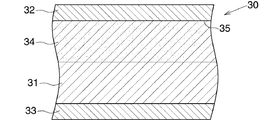
熱交換管(2)が上述したブレージングシートを用いてつくられていることから、図3に示すように、熱交換管(2)の管壁(30)は、前記ブレージングシートの芯材からなる芯材層(31)と、前記ブレージングシートの第1ろう材からなりかつ芯材層(31)の外面を覆う第1ろう材層(32)と、前記ブレージングシートの第2ろう材からなりかつ芯材層(31)の内面を覆う第2ろう材層(33)とよりなる。芯材層(31)の外面表層部にはZn拡散層(34)が形成されるとともに、Zn拡散層(34)の最深部分が熱交換管(2)の管壁(30)の最外面から70〜100μmの深さ位置にある。また、熱交換管(2)の管壁(30)の最外面のZn濃度は0.55質量%以上であり、Zn拡散層(34)に、芯材層(31)と第1ろう材層(32)との境界部分(35)の自然電位よりも41mV以上高くなった自然電位を有する高電位部分が存在している。管壁(30)における芯材層(31)と第1ろう材層(32)との境界部分(35)は、管壁(30)の最外面から17.7〜35.5μmの深さ位置に存在する。なお、ろう付の際にろう材が流れるので、芯材層(31)と第2ろう材層(33)との境界部分(36)を特定することはできない。ここで、熱交換管(2)の管壁(30)とは、下側平坦壁(11)、上側平坦壁(12)を形成する分割壁(22)および両側壁(13)である。 Since the heat exchange pipe (2) is made using the brazing sheet described above, the tube wall (30) of the heat exchange pipe (2) is a core made of the core material of the brazing sheet, as shown in FIG. A brazing material layer (31), a first brazing material layer (32) made of the first brazing material of the brazing sheet and covering the outer surface of the core material layer (31), and a second brazing material of the brazing sheet and the core The second brazing material layer (33) covers the inner surface of the material layer (31). A Zn diffusion layer (34) is formed on the outer surface layer of the core material layer (31), and the deepest portion of the Zn diffusion layer (34) is formed from the outermost surface of the tube wall (30) of the heat exchange tube (2). It exists in the depth position of 70-100 micrometers. Further, the Zn concentration on the outermost surface of the tube wall (30) of the heat exchange tube (2) is 0.55 mass% or more, and the core material layer (31) and the first brazing material layer are formed on the Zn diffusion layer (34). There is a high potential portion having a natural potential that is 41 mV or more higher than the natural potential at the boundary portion (35) with (32). The boundary part (35) between the core material layer (31) and the first brazing material layer (32) in the tube wall (30) is located at a depth of 17.7 to 35.5 μm from the outermost surface of the tube wall (30). Exists. Since the brazing material flows during brazing, the boundary portion (36) between the core material layer (31) and the second brazing material layer (33) cannot be specified. Here, the pipe wall (30) of the heat exchange pipe (2) is the lower flat wall (11), the dividing wall (22) forming the upper flat wall (12), and both side walls (13).
なお、上述した熱交換管素材用ブレージングシートの肉厚を170μm以上としたのは、次の理由による。すなわち、熱交換管(2)の管壁(30)の芯材層(31)に形成されるZn拡散層(34)の最深部分が熱交換管(2)の管壁(30)の最外面から70〜100μmの深さ位置にあるので、前記熱交換管素材用ブレージングシートの肉厚が170μ未満であると、管壁(30)の全肉厚に対するZn拡散層(34)の厚みの比率が大きくなり、熱交換管(2)の管壁(30)の外面からの腐食がZn拡散層(34)に存在する前記高電位部分で止まったとしても、熱交換管(2)の十分な耐食性および耐圧性が確保できなくなる。 The thickness of the above-described brazing sheet for heat exchange tube material was set to 170 μm or more for the following reason. That is, the deepest portion of the Zn diffusion layer (34) formed on the core layer (31) of the tube wall (30) of the heat exchange tube (2) is the outermost surface of the tube wall (30) of the heat exchange tube (2). Since the thickness of the brazing sheet for heat exchange tube material is less than 170 μm, the ratio of the thickness of the Zn diffusion layer (34) to the total thickness of the tube wall (30) Even if the corrosion from the outer surface of the pipe wall (30) of the heat exchange pipe (2) stops at the high potential portion existing in the Zn diffusion layer (34), sufficient heat exchange pipe (2) Corrosion resistance and pressure resistance cannot be ensured.
コルゲートフィン(3)は、Mn1.0〜1.5質量%、Zn1.2〜1.8質量%を含み、残部Alおよび不可避不純物からなるAl合金で形成されていることが好ましい。コルゲートフィン(3)において、Mn含有量を1.0〜1.5質量%としたのは、Mn含有量が少なすぎると、コルゲートフィン(3)自体の強度を十分に確保することができず、多すぎると強度が高くなりすぎて成形性が低下するからである。また、コルゲートフィン(3)において、Zn含有量を1.2〜1.8質量%としたのは、Zn含有量が少なすぎるとコルゲートフィン(3)が犠牲陽極として働くなくなって熱交換管(2)の耐食性が低下し、多すぎるとコルゲートフィン(3)の耐食性が不十分になるからである。 The corrugated fin (3) preferably contains Mn 1.0 to 1.5 mass%, Zn 1.2 to 1.8 mass%, and is formed of an Al alloy composed of the balance Al and inevitable impurities. In the corrugated fin (3), the Mn content is set to 1.0 to 1.5% by mass. If the Mn content is too small, the strength of the corrugated fin (3) itself cannot be sufficiently secured. If the amount is too large, the strength becomes too high and the moldability deteriorates. In the corrugated fin (3), the Zn content is set to 1.2 to 1.8% by mass. If the Zn content is too small, the corrugated fin (3) does not work as a sacrificial anode and the heat exchange tube ( This is because the corrosion resistance of 2) decreases, and if too much, the corrosion resistance of the corrugated fin (3) becomes insufficient.
コルゲートフィン(3)には、不可避不純物として、Si0.6質量%以下、Fe0.5質量%以下、Cu0.05質量%以下およびCr0.12質量%以下が含まれている。Fe含有量が多いとコルゲートフィン(3)の耐食性が不十分になり、Cu含有量が多いとコルゲートフィン(3)が犠牲陽極として働かなくなって熱交換管(2)の耐食性が低下するからである。なお、不可避不純物としてのSi、Fe、CuおよびCrの含有量は0の場合もある。 The corrugated fin (3) contains, as inevitable impurities, Si 0.6 mass% or less, Fe 0.5 mass% or less, Cu 0.05 mass% or less, and Cr 0.12 mass% or less. If the Fe content is high, the corrosion resistance of the corrugated fin (3) will be insufficient. If the Cu content is too high, the corrugated fin (3) will not function as a sacrificial anode and the corrosion resistance of the heat exchange tube (2) will be reduced. is there. Note that the contents of Si, Fe, Cu, and Cr as inevitable impurities may be zero.
左右のヘッダタンク(4)(5)は、両端が開口した筒状のアルミニウム製タンク本体(26)と、タンク本体(26)の両端部にろう付されてタンク本体(26)の両端開口を閉鎖するアルミニウム製閉鎖部材(27)とからなる。タンク本体(26)は、適当な合金組成を有するアルミニウム製芯材、および適当な合金組成を有しかつ芯材の両面を覆うアルミニウム製ろう材からなるブレージングシートを筒状に曲げて両側縁部が部分的に重ね合わされた筒状のタンク本体素材を得るとともに、タンク本体素材の側縁部どうしをろう付することによりつくられている。 The left and right header tanks (4) and (5) are brazed to both ends of the cylindrical aluminum tank body (26) and both ends of the tank body (26). An aluminum closing member (27) for closing. The tank body (26) is formed by bending a brazing sheet made of an aluminum core material having an appropriate alloy composition and an aluminum brazing material having an appropriate alloy composition and covering both sides of the core material into both side edges. Is obtained by brazing the tank body material, which is partially overlapped with each other, and brazing the side edges of the tank body material.
仕切板(7)、閉鎖部材(27)、入口部材(8)および出口部材(9)は適当な材質のアルミニウムで形成されている。 The partition plate (7), the closing member (27), the inlet member (8) and the outlet member (9) are made of a suitable material of aluminum.
コンデンサ(1)は、以下に述べる方法で製造される。 The capacitor (1) is manufactured by the method described below.
まず、上述した合金組成を有するAl合金製芯材と、上述した合金組成を有しかつ芯材の片面を覆うAl合金製第1ろう材と、上述した合金組成を有しかつ芯材の他面を覆うAl合金製第2ろう材とからなる肉厚が170μm以上であるブレージングシートを、第1ろう材が外面側にくるように曲げることにより、熱交換管(2)と同様な形状で、かつ各部がろう付されていない形状の熱交換管素材をつくる。熱交換素材用のブレージングシートにおける第1ろう材のクラッド率は16〜22%である。また、第2ろう材のクラッド率は8〜10%であることが好ましい。 First, an Al alloy core material having the above-described alloy composition, an Al alloy first brazing material having the above-described alloy composition and covering one surface of the core material, an alloy composition having the above-described alloy composition and the other core material By bending a brazing sheet composed of an Al alloy second brazing material covering the surface and having a wall thickness of 170 μm or more so that the first brazing material is on the outer surface side, the shape is similar to that of the heat exchange tube (2). In addition, a heat exchange tube material having a shape in which each part is not brazed is made. The clad rate of the first brazing material in the brazing sheet for heat exchange material is 16 to 22% . Further, it is preferable that the cladding of the second brazing material is 8 to 10%.
また、上述した合金組成を有するベア材製コルゲートフィン(3)と、適当な合金組成を有するサイドプレート(6)、仕切板(7)、閉鎖部材(27)、入口部材(8)および出口部材(9)を用意する。 Further, the bare corrugated fin (3) having the alloy composition described above, the side plate (6), the partition plate (7), the closing member (27), the inlet member (8), and the outlet member having an appropriate alloy composition. Prepare (9).
さらに、適当な合金組成を有するアルミニウム製芯材、および適当な合金組成を有しかつ芯材の両面を覆うアルミニウム製ろう材からなるブレージングシートを筒状に曲げて両側縁部が部分的に重ね合わされた筒状のタンク本体素材をつくる。 Further, a brazing sheet made of an aluminum core material having an appropriate alloy composition and an aluminum brazing material having an appropriate alloy composition and covering both surfaces of the core material is bent into a cylindrical shape, and both side edges are partially overlapped. Make a cylindrical tank body material.
ついで、熱交換管素材とコルゲートフィン(3)とサイドプレート(6)とを組み合わせるとともに、タンク本体素材と閉鎖部材(27)と仕切板(7)とを組み合わせ、入口部材(8)および出口部材(9)を決められた位置に配置する。 Next, the heat exchange tube material, the corrugated fin (3) and the side plate (6) are combined, and the tank body material, the closing member (27) and the partition plate (7) are combined, and the inlet member (8) and the outlet member are combined. Place (9) in the determined position.
その後、熱交換管素材、コルゲートフィン(3)、サイドプレート(6)、タンク本体素材、仕切板(7)、閉鎖部材(27)、入口部材(8)および出口部材(9)の組み合わせ体を所定温度に加熱することによって、熱交換管素材の必要部分をろう付して熱交換管(2)を形成するとともに、タンク本体素材の継ぎ目部分をろう付してタンク本体(26)を形成し、さらにタンク本体(26)と仕切板(7)および閉鎖部材(27)とをろう付してヘッダタンク(4)(5)を形成する。また、熱交換管(2)の形成およびヘッダタンク(4)(5)の形成と同時に、熱交換管(2)とヘッダタンク(4)(5)、熱交換管(2)とコルゲートフィン(3)、コルゲートフィン(3)とサイドプレート(6)、ヘッダタンク(4)(5)と入口部材(8)および出口部材(9)をろう付する。こうして、コンデンサ(1)が製造される。 After that, the heat exchanger tube material, corrugated fin (3), side plate (6), tank body material, partition plate (7), closing member (27), inlet member (8) and outlet member (9) are combined. By heating to a predetermined temperature, the necessary part of the heat exchange tube material is brazed to form the heat exchange tube (2), and the joint of the tank body material is brazed to form the tank body (26). Furthermore, the tank body (26), the partition plate (7) and the closing member (27) are brazed to form the header tanks (4) and (5). Simultaneously with the formation of the heat exchange pipe (2) and the header tank (4) (5), the heat exchange pipe (2) and the header tank (4) (5), the heat exchange pipe (2) and the corrugated fin ( 3) The corrugated fins (3) and the side plates (6), the header tanks (4) and (5), the inlet member (8) and the outlet member (9) are brazed. Thus, the capacitor (1) is manufactured.
コンデンサ(1)の製造に用いられる前記熱交換管素材用のブレージングシートにおいて、芯材のCu含有量を0.3〜0.5質量%に限定するとともに、第1ろう材のZn含有量を2.0〜3.0質量%に限定し、さらに第1ろう材のクラッド率を16〜22%に限定したのは、次に述べる実験結果に基づくものである。
In the brazing sheet for the heat exchange tube material used in the manufacture of the capacitor (1), the Cu content of the core material is limited to 0.3 to 0.5% by mass, and the Zn content of the first brazing material is it is limited to 2.0 to 3.0 mass%, further to that limit the cladding of the
すなわち、表1に示す肉厚180μmの12種類のブレージングシートを用意した。 That is, 12 types of brazing sheets having a thickness of 180 μm shown in Table 1 were prepared.

なお、表1に示すブレージングシートにおける芯材のCuの含有量、第1ろう材のZnの含有量、および第1ろう材のクラッド率は表2に示す通りである。また、第2ろう材のクラッド率は10%である。 In addition, the Cu content of the core material, the Zn content of the first brazing material, and the cladding ratio of the first brazing material in the brazing sheet shown in Table 1 are as shown in Table 2. The clad rate of the second brazing material is 10%.
ついで、12種類のアルミニウムブレージングシートから60mm×120mmのテストピースを作成し、すべてのテストピースを、余熱室およびろう付室を窒素ガス雰囲気としたろう付炉中において、余熱室で500℃×10分間加熱した後、ろう付室で611℃×10分間加熱した。 Next, 60 mm × 120 mm test pieces were prepared from 12 types of aluminum brazing sheets, and all the test pieces were placed in a preheating chamber at a temperature of 500 ° C. × 10 in a brazing furnace in which the preheating chamber and the brazing chamber were in a nitrogen gas atmosphere. After heating for a minute, it heated in a brazing chamber for 611 degreeC x 10 minutes.
その後、すべてのテストピースに対してASTM G85−A3に基づくSWATT試験を行い、表面状態を観察した。その結果も表2に示す。表2のSWATT試験結果の欄における○印は浅い面腐食が発生していたことを示し、×印は深い部分腐食が発生していたことを示す。 Thereafter, a SWATT test based on ASTM G85-A3 was performed on all test pieces, and the surface state was observed. The results are also shown in Table 2. In the column of the SWATT test results in Table 2, a mark ◯ indicates that shallow surface corrosion has occurred, and a mark X indicates that deep partial corrosion has occurred.
上述した実験結果から、熱交換管素材用のブレージングシートにおいて、芯材のCu含有量を0.3〜0.5質量%に限定するとともに、第1ろう材のZn含有量を2.0〜3.0質量%に限定し、さらに第1ろう材のクラッド率を16〜22%に限定した。 From the experimental results described above, in the brazing sheet for the heat exchange tube material, the Cu content of the core material is limited to 0.3 to 0.5 mass%, and the Zn content of the first brazing material is 2.0 to 2.0%. It limited to 3.0 mass%, and also the clad rate of the 1st brazing material was limited to 16-22%.
以下、この発明の具体的実施例を比較例とともに説明する。
実施例
Cu0.40質量%、Mn0.8質量%、Ti0.1質量%を含み、残部Alおよび不可避不純物からなる芯材と、Si7.5質量%、Zn2.0質量%を含み、残部Alおよび不可避不純物からなり、かつ芯材の片面を覆う第1ろう材と、Si10質量%を含み、残部Alおよび不可避不純物からなり、かつ芯材の他面を覆う第2ろう材とからなる熱交換管形成用アルミニウムブレージングシートを用意した。熱交換管形成用アルミニウムブレージングシートにおける第1ろう材のクラッド率は16%であり、第2ろう材のクラッド率は10%である。芯材における不可避不純物としてのZn含有量は0である。なお、芯材における不可避不純物としてのSi含有量は0.09質量%、Fe含有量は0.09質量%である。また、第1ろう材における不可避不純物としてのCu含有量は0である。なお、第1ろう材における不可避不純物としてのFe含有量は0.25質量%である。さらに、第2ろう材における不可避不純物としてのCu含有量は0.04質量%、Fe含有量は0.28質量%である。さらに、芯材、第1ろう材および第2ろう材における上述した不可避不純物を除いた他の不可避不純物元素の個々の含有量は0.05質量%以下で、かつ当該他の不可避不純物元素の合計含有量は0.15質量%である。
Hereinafter, specific examples of the present invention will be described together with comparative examples.
Example Cu 0.40% by mass, Mn 0.8% by mass, Ti 0.1% by mass, balance Al and inevitable impurities core material, Si 7.5% by mass, Zn 2.0% by mass, the remaining Al and A heat exchange tube made of a first brazing material made of inevitable impurities and covering one side of the core material, and a second brazing material containing 10% by mass of Si, the balance being Al and inevitable impurities and covering the other surface of the core material A forming aluminum brazing sheet was prepared. The clad rate of the first brazing material in the aluminum brazing sheet for forming a heat exchange tube is 16%, and the clad rate of the second brazing material is 10%. The Zn content as an inevitable impurity in the core material is zero. In addition, Si content as an inevitable impurity in a core material is 0.09 mass%, and Fe content is 0.09 mass%. Further, the Cu content as an inevitable impurity in the first brazing material is zero. In addition, Fe content as an inevitable impurity in a 1st brazing material is 0.25 mass% . Further, the Cu content as an inevitable impurity in the second brazing material is 0.04% by mass, and the Fe content is 0.28% by mass. Furthermore, each content of the other inevitable impurity elements excluding the above-mentioned inevitable impurities in the core material, the first brazing material and the second brazing material is 0.05% by mass or less, and the total of the other inevitable impurity elements Content is 0.15 mass%.
また、Mn1.03質量%、Zn1.43質量%を含み、残部Alおよび不可避不純物からなるAl合金で形成されたベア材製コルゲートフィン(3)を用意した。コルゲートフィン(3)における不可避不純物としてのSi含有量は0.34質量%、Fe含有量は0.44質量%である。また、コルゲートフィン(3)における上述した不可避不純物を除いた他の不可避不純物元素の個々の含有量は0.05質量%以下で、かつ当該他の不可避不純物元素の合計含有量は0.15質量%である。 Further, a corrugated fin (3) made of a bare material made of an Al alloy containing Mn 1.03% by mass and Zn 1.43% by mass, and the balance Al and inevitable impurities was prepared. In the corrugated fin (3), the Si content as an inevitable impurity is 0.34% by mass, and the Fe content is 0.44% by mass. The individual content of other inevitable impurity elements excluding the above-mentioned inevitable impurities in the corrugated fin (3) is 0.05% by mass or less, and the total content of the other inevitable impurity elements is 0.15 mass. %.
さらに、適当な合金組成を有する仕切板(7)、閉鎖部材(27)、入口部材(8)および出口部材(9)を用意した。さらに、適当な合金組成を有するアルミニウム製芯材と、適当な合金組成を有しかつ芯材の両面を覆うアルミニウム製ろう材とからなるタンク本体用のブレージングシートの幅方向の中央部に管挿入穴を形成した後、当該ブレージングシートを筒状に成形して両側縁部どうしを部分的に重ね合わせることにより、タンク本体(26)と同様な形状で、かつ両側縁部どうしがろう付されていない形状のタンク本体素材をつくった。 Further, a partition plate (7), a closing member (27), an inlet member (8) and an outlet member (9) having an appropriate alloy composition were prepared. Furthermore, a tube is inserted into the center portion in the width direction of the brazing sheet for the tank body, which comprises an aluminum core material having an appropriate alloy composition and an aluminum brazing material having an appropriate alloy composition and covering both surfaces of the core material. After forming the hole, the brazing sheet is formed into a cylindrical shape, and the edges on both sides are partially overlapped to form the same shape as the tank body (26), and the edges on both sides are brazed. Made tank body material with no shape.
その後、上述した方法と同様にしてコンデンサ(1)を製造した。 Thereafter, a capacitor (1) was produced in the same manner as described above.
製造されたコンデンサ(1)から5つの熱交換管(2)を切り出し、各熱交換管(2)の管壁(30)を観察したところ、管壁(30)の芯材層(31)の外面表層部にZn拡散層(34)が形成されていた。そして、Zn拡散層(34)の最深部分における管壁(30)最外面からの深さ位置、および管壁(30)最外面のZn濃度を測定したところ、図4に示す通り、Zn拡散層(34)の最深部分における管壁(30)の最外面からの深さ位置は70〜100μm、管壁(30)最外面のZn濃度は0.55質量%以上であった。なお、管壁の肉厚は180μmである。 Five heat exchange tubes (2) were cut out from the manufactured capacitor (1) and the tube wall (30) of each heat exchange tube (2) was observed. As a result, the core layer (31) of the tube wall (30) was observed. A Zn diffusion layer (34) was formed on the outer surface layer. Then, the depth position from the outermost surface of the tube wall (30) in the deepest portion of the Zn diffusion layer (34) and the Zn concentration of the outermost surface of the tube wall (30) were measured. As shown in FIG. The depth position from the outermost surface of the tube wall (30) in the deepest portion of (34) was 70 to 100 μm, and the Zn concentration on the outermost surface of the tube wall (30) was 0.55 mass% or more. The wall thickness of the tube wall is 180 μm.
また、製造されたコンデンサ(1)から1つの熱交換管(2)および当該熱交換管(2)にろう付されたコルゲートフィン(3)を切り取り、熱交換管(2)の管壁(30)最外面の自然電位、Zn拡散層(34)の自然電位、コルゲートフィン(3)の自然電位および熱交換管(2)とコルゲートフィン(3)との間に形成されたフィレットの自然電位を測定したところ、表3に示す通りとなった。 Further, one heat exchange pipe (2) and the corrugated fin (3) brazed to the heat exchange pipe (2) are cut out from the manufactured condenser (1), and the wall (30) of the heat exchange pipe (2) is cut. ) The natural potential of the outermost surface, the natural potential of the Zn diffusion layer (34), the natural potential of the corrugated fin (3) and the natural potential of the fillet formed between the heat exchange tube (2) and the corrugated fin (3). When measured, it was as shown in Table 3.
また、製造されたコンデンサ(1)から1つの熱交換管(2)を切り取り、管壁(30)最外面からの異なる深さ位置の自然電位を測定したところ、図5に示す通りとなった。なお、管壁(30)の肉厚は180μmであった。図5において、管壁(30)における芯材層(31)と第1ろう材層(32)との境界部分(35)は、直線Aで示す位置、すなわち最外面から28.8μmの深さ位置にあった。また、Zn拡散層(34)の最深部の深さ位置は、管壁(30)の最外面から100μmの深さ位置にあった。図5に示す結果から、Zn拡散層(34)に、芯材層(31)と第1ろう材層(32)との境界部分(35)の自然電位よりも41mV以上高くなっている部分が存在していることが分かる。 Also, one heat exchange pipe (2) was cut from the manufactured condenser (1), and the natural potentials at different depth positions from the outermost surface of the pipe wall (30) were measured, and the result was as shown in FIG. . The wall thickness of the tube wall (30) was 180 μm. In FIG. 5, the boundary portion (35) between the core material layer (31) and the first brazing material layer (32) in the pipe wall (30) is a position indicated by a straight line A, that is, a depth of 28.8 μm from the outermost surface. Was in position. The depth position of the deepest portion of the Zn diffusion layer (34) was 100 μm deep from the outermost surface of the tube wall (30). From the results shown in FIG. 5, the Zn diffusion layer (34) has a portion that is 41 mV higher than the natural potential of the boundary portion (35) between the core material layer (31) and the first brazing material layer (32). You can see that it exists.
さらに、製造されたコンデンサ(1)についてCCT試験を240日間行っ後、熱交換管(2)を5本切り出し、熱交換管(2)の管壁(30)の最外面からの腐食深さを測定したところ、最大腐食深さは46μmであった。
比較例
Cu0.4質量%、Mn0.8質量%、Ti0.1質量%を含み、残部Alおよび不可避不純物からなる芯材と、Si7.5質量%、Zn2.0質量%を含み、残部Alおよび不可避不純物からなり、かつ芯材の片面を覆う第1ろう材と、実施例と同じ合金組成の第2ろう材とからなる熱交換管形成用アルミニウムブレージングシートを用意した。熱交換管形成用アルミニウムブレージングシートにおける第1ろう材のクラッド率は16%であり、第2ろう材のクラッド率は10%である。なお、芯材における不可避不純物としてのSi含有量は0.1質量%、Fe含有量は0.1質量%、Zn含有量は0.01質量%である。また、第1ろう材における不可避不純物としてのCu含有量は0.02質量%、Fe含有量は0.27質量%である。また、芯材および両ろう材における上述した不可避不純物を除いた他の不可避不純物元素の個々の含有量は0.05質量%以下で、かつ当該他の不可避不純物元素の合計含有量は0.15質量%である。
Furthermore, after conducting a CCT test on the manufactured capacitor (1) for 240 days, cut out five heat exchange tubes (2) and determine the corrosion depth from the outermost surface of the tube wall (30) of the heat exchange tube (2). When measured, the maximum corrosion depth was 46 μm.
Comparative Example Cu 0.4% by mass, Mn 0.8% by mass, Ti 0.1% by mass, the balance comprising Al and inevitable impurities, Si 7.5% by mass, Zn 2.0% by mass, the remaining Al and An aluminum brazing sheet for forming a heat exchange tube comprising a first brazing material made of unavoidable impurities and covering one side of the core material and a second brazing material having the same alloy composition as that of the example was prepared. The clad rate of the first brazing material in the aluminum brazing sheet for forming a heat exchange tube is 16%, and the clad rate of the second brazing material is 10%. In addition, Si content as an inevitable impurity in a core material is 0.1 mass%, Fe content is 0.1 mass%, Zn content is 0.01 mass%. Moreover, Cu content as an inevitable impurity in a 1st brazing material is 0.02 mass%, and Fe content is 0.27 mass%. Further, the individual contents of other inevitable impurity elements excluding the above-mentioned inevitable impurities in the core material and the both brazing materials are 0.05% by mass or less, and the total content of the other inevitable impurity elements is 0.15. % By mass.
その他は、上述した実施例と同様の条件で、コンデンサを製造した。 Other than that, a capacitor was manufactured under the same conditions as in the above-described example.
製造されたコンデンサから1つの熱交換管を切り取り、管壁最外面からの異なる深さ位置の自然電位を測定したところ、図6に示す通りとなった。なお、管壁の肉厚は225μmであった。図6において、管壁における芯材層と第1ろう材層との境界部分は、直線Bで示す位置、すなわち最外面から33.8μmの深さ位置にあった。また、Zn拡散層の最深部の深さ位置は、管壁の最外面から100μmの深さ位置にあった。図6に示す結果から、Zn拡散層には、芯材層と第1ろう材層との境界部分の自然電位よりも最大で29mV以上高くなっている部分が存在するだけであることが分かる。 One heat exchange tube was cut out from the manufactured condenser, and the natural potentials at different depth positions from the outermost surface of the tube wall were measured, and the result was as shown in FIG. The wall thickness of the tube wall was 225 μm. In FIG. 6, the boundary portion between the core material layer and the first brazing material layer on the tube wall was at the position indicated by the straight line B, that is, at a depth position of 33.8 μm from the outermost surface. The depth position of the deepest portion of the Zn diffusion layer was 100 μm deep from the outermost surface of the tube wall. From the results shown in FIG. 6, it can be seen that the Zn diffusion layer only has a portion that is 29 mV or more higher than the natural potential at the boundary portion between the core material layer and the first brazing material layer.
さらに、製造されたコンデンサについてCCT試験を240日間行っ後、熱交換管(2)を5本切り出し、熱交換管の管壁の最外面からの腐食深さを測定したところ、最大腐食深さは100μmであった。 Furthermore, after the CCT test was conducted for 240 days on the manufactured capacitor, five heat exchange tubes (2) were cut out and the corrosion depth from the outermost surface of the heat exchange tube wall was measured. It was 100 μm.
この発明による熱交換器は、カーエアコン用コンデンサに好適に用いられる。 The heat exchanger according to the present invention is preferably used for a condenser for a car air conditioner.
(1):コンデンサ(熱交換器)
(2):扁平状熱交換管
(3):コルゲートフィン
(30):管壁
(31):芯材層
(32):第1ろう材層
(33):第2ろう材層
(34):Zn拡散層
(35):芯材層と第1ろう材層との境界部分
(1): Capacitor (heat exchanger)
(2): Flat heat exchange tube
(3): Corrugated fin
(30): Pipe wall
(31): Core material layer
(32): 1st brazing filler metal layer
(33): Second brazing filler metal layer
(34): Zn diffusion layer
(35): Boundary portion between core material layer and first brazing material layer
Claims (4)
熱交換管が、Cu0.3〜0.5質量%、Mn0.6〜1.0質量%、Ti0.05〜0.15質量%を含み、残部Alおよび不可避不純物からなるとともに、不可避不純物としてのZnの含有量が0であるAl合金で形成された芯材と、Si7.0〜8.0質量%、Zn2.0〜3.0質量%を含み、残部Alおよび不可避不純物からなるとともに、不可避不純物としてのCuの含有量が0であるAl合金で形成され、かつ芯材の片面を、クラッド率が16〜22%となるように覆う第1ろう材と、Si9.5〜10.5質量%を含み、残部Alおよび不可避不純物からなるAl合金で形成され、かつ芯材の他面を覆う第2ろう材とからなる肉厚170μm以上のブレージングシートが、第1ろう材が外側に来るように曲げられて扁平中空状の熱交換管素材とされるとともに、熱交換管素材の必要部分をろう付することによりつくられており、フィンがアルミニウムベア材からなり、
熱交換管の管壁が、前記芯材からなる芯材層と、前記第1ろう材からなりかつ芯材層の外面を覆う第1ろう材層と、前記第2ろう材からなりかつ芯材層の内面を覆う第2ろう材層とよりなり、芯材層の外面表層部にZn拡散層が形成されるとともに、当該Zn拡散層の最深部分が熱交換管の管壁の最外面から70〜100μmの深さ位置にあり、熱交換管の管壁の最外面のZn濃度が0.55質量%以上であり、前記Zn拡散層に、芯材層と第1ろう材層との境界部分の自然電位よりも41mV以上高くなった自然電位を有する高電位部分が存在している熱交換器。 Heat exchange with a plurality of flat heat exchange tubes arranged at intervals in the thickness direction and adjacent heat exchange tubes with the longitudinal direction in the same direction and the width direction in the ventilation direction In a heat exchanger having fins brazed to tubes,
The heat exchange tube contains 0.3 to 0.5% by mass of Cu, 0.6 to 1.0% by mass of Mn, 0.05 to 0.15% by mass of Ti, and is composed of the balance Al and unavoidable impurities . It contains a core material made of an Al alloy with a Zn content of 0 , Si 7.0-8.0 mass%, Zn 2.0-3.0 mass%, and consists of the balance Al and inevitable impurities , and is unavoidable A first brazing material which is formed of an Al alloy having a Cu content of 0 as an impurity and covers one side of the core material so that the cladding rate is 16 to 22%; and Si 9.5 to 10.5 mass The brazing sheet having a thickness of 170 μm or more formed of an Al alloy composed of the remaining Al and inevitable impurities and including the second brazing material covering the other surface of the core so that the first brazing material comes outside Bend into flat hollow Together are of a heat exchanger tube material, a necessary portion of the heat exchange tube material is made by brazing, the fin is made of aluminum bare material,
The tube wall of the heat exchange tube is made of the core material layer made of the core material, the first brazing material layer made of the first brazing material and covering the outer surface of the core material layer, and the core material made of the second brazing material. The Zn diffusion layer is formed on the outer surface layer portion of the core material layer, and the deepest portion of the Zn diffusion layer is 70 from the outermost surface of the tube wall of the heat exchange tube. The Zn concentration on the outermost surface of the tube wall of the heat exchange tube is 0.55% by mass or more at a depth position of ˜100 μm, and the Zn diffusion layer has a boundary portion between the core material layer and the first brazing material layer A heat exchanger having a high potential portion having a natural potential that is 41 mV or more higher than the natural potential.
Cu0.3〜0.5質量%、Mn0.6〜1.0質量%、Ti0.05〜0.15質量%を含み、残部Alおよび不可避不純物からなるとともに、不可避不純物としてのZnの含有量が0であるAl合金で形成された芯材と、Si7.0〜8.0質量%、Zn2.0〜3.0質量%を含み、残部Alおよび不可避不純物からなるとともに、不可避不純物としてのCuの含有量が0であるAl合金で形成され、かつ芯材の片面を、クラッド率が16〜22%となるように覆う第1ろう材と、Si9.5〜10.5質量%を含み、残部Alおよび不可避不純物からなるAl合金で形成され、かつ芯材の他面を覆う第2ろう材とからなる肉厚170μm以上のブレージングシートを曲げて扁平中空状の熱交換管素材をつくるとともに、熱交換管素材の必要部分をろう付して熱交換管を形成すること、ならびに熱交換管の形成と同時に形成された熱交換管とアルミニウムベア材製フィンとをろう付することを含む熱交換器の製造方法。 A method for producing a heat exchanger according to claim 1, comprising:
Cu 0.3-0.5% by mass, Mn 0.6-1.0% by mass, Ti 0.05-0.15% by mass, comprising the balance Al and inevitable impurities, and the content of Zn as an inevitable impurity is A core material formed of an Al alloy that is 0 , Si 7.0 to 8.0 mass%, Zn 2.0 to 3.0 mass%, and the balance consisting of Al and inevitable impurities, and Cu as an inevitable impurity A first brazing material that is formed of an Al alloy having a content of 0 and covers one side of the core material so that the cladding rate is 16 to 22%; and Si 9.5 to 10.5% by mass, and the balance A flat hollow heat exchange tube material is formed by bending a brazing sheet having a thickness of 170 μm or more formed of an Al alloy composed of Al and inevitable impurities and comprising a second brazing material covering the other surface of the core material. Exchange tube material That the necessary portions are brazed to form a heat exchange tubes, and a manufacturing method of a heat exchanger comprising a simultaneously formed heat exchange tubes and an aluminum bare material made fin and forming a heat exchange tube to brazing.
Priority Applications (3)
| Application Number | Priority Date | Filing Date | Title |
|---|---|---|---|
| JP2015112080A JP6564620B2 (en) | 2015-06-02 | 2015-06-02 | Heat exchanger and manufacturing method thereof |
| US15/153,740 US20160356562A1 (en) | 2015-06-02 | 2016-05-13 | Heat exchanger and method of manufacturing the same |
| CN201610346492.9A CN106216973B (en) | 2015-06-02 | 2016-05-23 | Heat exchanger and its manufacturing method |
Applications Claiming Priority (1)
| Application Number | Priority Date | Filing Date | Title |
|---|---|---|---|
| JP2015112080A JP6564620B2 (en) | 2015-06-02 | 2015-06-02 | Heat exchanger and manufacturing method thereof |
Publications (3)
| Publication Number | Publication Date |
|---|---|
| JP2016223725A JP2016223725A (en) | 2016-12-28 |
| JP2016223725A5 JP2016223725A5 (en) | 2018-04-05 |
| JP6564620B2 true JP6564620B2 (en) | 2019-08-21 |
Family
ID=57452380
Family Applications (1)
| Application Number | Title | Priority Date | Filing Date |
|---|---|---|---|
| JP2015112080A Expired - Fee Related JP6564620B2 (en) | 2015-06-02 | 2015-06-02 | Heat exchanger and manufacturing method thereof |
Country Status (3)
| Country | Link |
|---|---|
| US (1) | US20160356562A1 (en) |
| JP (1) | JP6564620B2 (en) |
| CN (1) | CN106216973B (en) |
Families Citing this family (7)
| Publication number | Priority date | Publication date | Assignee | Title |
|---|---|---|---|---|
| EP2960609B1 (en) * | 2014-06-26 | 2022-10-05 | Valeo Autosystemy SP. Z.O.O. | Manifold, in particular for use in a cooler of a cooling system |
| JP6843012B2 (en) * | 2017-07-14 | 2021-03-17 | 株式会社日本クライメイトシステムズ | Heat exchanger tube |
| JP2019045091A (en) * | 2017-09-05 | 2019-03-22 | 株式会社ケーヒン・サーマル・テクノロジー | Heat exchanger |
| WO2019056855A1 (en) * | 2017-09-20 | 2019-03-28 | 杭州三花家电热管理系统有限公司 | Heat exchange assembly, heat exchange system, and indoor heating system |
| CN112344763B (en) * | 2019-08-07 | 2022-04-01 | 丹佛斯有限公司 | Method for manufacturing heat exchanger |
| CN112635418A (en) * | 2019-10-08 | 2021-04-09 | 全亿大科技(佛山)有限公司 | Liquid cooling radiator |
| CN110779375B (en) * | 2019-11-01 | 2021-04-30 | 郑州机械研究所有限公司 | Aluminum alloy composite pipe for radiator manufacturing and preparation method thereof |
Family Cites Families (26)
| Publication number | Priority date | Publication date | Assignee | Title |
|---|---|---|---|---|
| US2821014A (en) * | 1951-05-31 | 1958-01-28 | Aluminum Co Of America | Composite aluminous metal article |
| US3917151A (en) * | 1973-02-08 | 1975-11-04 | Kaiser Aluminium Chem Corp | Vacuum brazing process |
| US4146164A (en) * | 1977-11-09 | 1979-03-27 | Aluminum Company Of America | Production of aluminum brazing sheet |
| JPS5433836A (en) * | 1978-08-08 | 1979-03-12 | Nippon Denso Co | Method of making aluminum heat exchanger |
| JPS61255760A (en) * | 1985-05-09 | 1986-11-13 | Mitsubishi Heavy Ind Ltd | Production of heat exchanger |
| JP2564190B2 (en) * | 1988-09-12 | 1996-12-18 | 株式会社神戸製鋼所 | Aluminum alloy composite for brazing |
| US5350436A (en) * | 1992-11-24 | 1994-09-27 | Kobe Alcoa Transportation Products Ltd. | Aluminum alloy composite material for brazing |
| US6063510A (en) * | 1996-03-05 | 2000-05-16 | The Furukawa Electric Co., Ltd. | Aluminum alloy brazing sheet for use in vacuum brazing |
| JP4451974B2 (en) * | 2000-08-10 | 2010-04-14 | 古河スカイ株式会社 | Aluminum alloy brazing sheet for heat exchanger |
| US6555251B2 (en) * | 2000-12-21 | 2003-04-29 | Alcoa Inc. | Multi-layer, heat treatable brazing sheet with aluminum interlayer |
| WO2003028946A1 (en) * | 2001-09-28 | 2003-04-10 | Furukawa-Sky Aluminum Corp. | Method for brazing of aluminum or aluminum alloy material and aluminum alloy brazing sheet |
| FR2832497B1 (en) * | 2001-11-19 | 2004-05-07 | Pechiney Rhenalu | ALUMINUM ALLOY STRIPS FOR HEAT EXCHANGERS |
| US7255932B1 (en) * | 2002-04-18 | 2007-08-14 | Alcoa Inc. | Ultra-longlife, high formability brazing sheet |
| US20060102328A1 (en) * | 2004-11-16 | 2006-05-18 | Denso Corporation | Aluminum heat exchanger and manufacturing method thereof |
| JP4056014B2 (en) * | 2005-04-12 | 2008-03-05 | 株式会社神戸製鋼所 | Aluminum alloy brazing sheet and aluminum alloy tube for heat exchanger |
| US20100147500A1 (en) * | 2005-08-31 | 2010-06-17 | Showa Denko K.K. | Clad plate and process for production thereof |
| JP4477668B2 (en) * | 2007-12-25 | 2010-06-09 | 株式会社神戸製鋼所 | Aluminum alloy brazing sheet |
| US20110204124A1 (en) * | 2008-11-10 | 2011-08-25 | Aleris Aluminum Koblenz Gmbh | Process for fluxless brazing of aluminium and brazing filler alloy for use therein |
| CA2744616C (en) * | 2008-12-23 | 2013-05-28 | Novelis Inc. | Clad metal sheet and heat exchanger tubing etc. made therefrom |
| DE102009055608A1 (en) * | 2009-11-25 | 2011-05-26 | Behr Gmbh & Co. Kg | Brazed aluminum heat exchanger |
| JP5190078B2 (en) * | 2010-03-10 | 2013-04-24 | 株式会社神戸製鋼所 | Brazing sheet for aluminum alloy brazing sheet and design method thereof |
| FR2975402B1 (en) * | 2011-05-20 | 2013-05-10 | Constellium France | ALLOYS FOR THERMAL HEAT EXCHANGER TUBE WITH INTERNAL PROTECTIVE VENEER AND WITH BREAKER BREAKER |
| US8932728B2 (en) * | 2012-03-15 | 2015-01-13 | Kobe Steel, Ltd. | Aluminum-alloy clad sheet |
| JP6050958B2 (en) * | 2012-06-01 | 2016-12-21 | 株式会社ケーヒン・サーマル・テクノロジー | Flat heat exchanger tube |
| JP6236290B2 (en) * | 2012-11-13 | 2017-11-22 | 株式会社デンソー | Aluminum alloy clad material and heat exchanger assembled with a tube formed from the clad material |
| JP6106530B2 (en) * | 2013-06-07 | 2017-04-05 | 株式会社ケーヒン・サーマル・テクノロジー | Method for preventing corrosion of heat exchange pipe outer surface made of extruded aluminum and method for producing heat exchanger |
-
2015
- 2015-06-02 JP JP2015112080A patent/JP6564620B2/en not_active Expired - Fee Related
-
2016
- 2016-05-13 US US15/153,740 patent/US20160356562A1/en not_active Abandoned
- 2016-05-23 CN CN201610346492.9A patent/CN106216973B/en not_active Expired - Fee Related
Also Published As
| Publication number | Publication date |
|---|---|
| JP2016223725A (en) | 2016-12-28 |
| US20160356562A1 (en) | 2016-12-08 |
| CN106216973B (en) | 2019-06-18 |
| CN106216973A (en) | 2016-12-14 |
Similar Documents
| Publication | Publication Date | Title |
|---|---|---|
| JP6564620B2 (en) | Heat exchanger and manufacturing method thereof | |
| JP2016223725A5 (en) | ||
| JP6115892B2 (en) | Aluminum alloy brazing sheet for fins, heat exchanger and heat exchanger manufacturing method | |
| US9827638B2 (en) | Heat exchanger and method of manufacturing the same | |
| US9744610B2 (en) | Clad material, method of manufacturing brazed pipe, and brazed pipe | |
| EP1558788A1 (en) | Heat exchanger, heat exchanger tube member, heat exchanger fin member and process for fabricating the heat exchanger | |
| JP2013072607A (en) | Method of manufacturing heat exchanger | |
| JP5891026B2 (en) | Clad material | |
| JP6590536B2 (en) | Clad material and pipe manufacturing method | |
| JP4804895B2 (en) | Manufacturing method of heat exchanger | |
| JP2004170061A (en) | Heat exchanger, pipe material and fin material of heat exchanger and manufacturing method of heat exchanger | |
| JP2017002341A5 (en) | ||
| JP2011163666A5 (en) | ||
| JP2019070499A (en) | Method of manufacturing heat exchanger | |
| JP2011257084A (en) | All-aluminum heat exchanger | |
| JP5352276B2 (en) | Manufacturing method of heat exchanger | |
| JP5302114B2 (en) | Aluminum alloy brazing sheet for vacuum brazing | |
| JP5963112B2 (en) | Aluminum heat exchanger for room air conditioner | |
| JP2009216287A (en) | Heat exchanger | |
| JP2010107147A (en) | Heat exchanger and method of manufacturing the same | |
| JP2008168332A (en) | Manufacturing method of flat tube | |
| JP5276807B2 (en) | Heat exchanger | |
| JP2009030814A (en) | Tube for heat exchanger and heat exchanger | |
| US20190072344A1 (en) | Heat exchanger | |
| JP5124817B2 (en) | Heat exchanger and manufacturing method thereof |
Legal Events
| Date | Code | Title | Description |
|---|---|---|---|
| A521 | Request for written amendment filed |
Free format text: JAPANESE INTERMEDIATE CODE: A523 Effective date: 20180222 |
|
| A621 | Written request for application examination |
Free format text: JAPANESE INTERMEDIATE CODE: A621 Effective date: 20180222 |
|
| A977 | Report on retrieval |
Free format text: JAPANESE INTERMEDIATE CODE: A971007 Effective date: 20181225 |
|
| A131 | Notification of reasons for refusal |
Free format text: JAPANESE INTERMEDIATE CODE: A131 Effective date: 20190108 |
|
| A521 | Request for written amendment filed |
Free format text: JAPANESE INTERMEDIATE CODE: A523 Effective date: 20190227 |
|
| TRDD | Decision of grant or rejection written | ||
| A01 | Written decision to grant a patent or to grant a registration (utility model) |
Free format text: JAPANESE INTERMEDIATE CODE: A01 Effective date: 20190702 |
|
| A61 | First payment of annual fees (during grant procedure) |
Free format text: JAPANESE INTERMEDIATE CODE: A61 Effective date: 20190729 |
|
| R150 | Certificate of patent or registration of utility model |
Ref document number: 6564620 Country of ref document: JP Free format text: JAPANESE INTERMEDIATE CODE: R150 |
|
| S533 | Written request for registration of change of name |
Free format text: JAPANESE INTERMEDIATE CODE: R313533 |
|
| R350 | Written notification of registration of transfer |
Free format text: JAPANESE INTERMEDIATE CODE: R350 |
|
| S111 | Request for change of ownership or part of ownership |
Free format text: JAPANESE INTERMEDIATE CODE: R313113 |
|
| R360 | Written notification for declining of transfer of rights |
Free format text: JAPANESE INTERMEDIATE CODE: R360 |
|
| R360 | Written notification for declining of transfer of rights |
Free format text: JAPANESE INTERMEDIATE CODE: R360 |
|
| R371 | Transfer withdrawn |
Free format text: JAPANESE INTERMEDIATE CODE: R371 |
|
| S111 | Request for change of ownership or part of ownership |
Free format text: JAPANESE INTERMEDIATE CODE: R313113 |
|
| R350 | Written notification of registration of transfer |
Free format text: JAPANESE INTERMEDIATE CODE: R350 |
|
| LAPS | Cancellation because of no payment of annual fees |