JP6576702B2 - 車両用内燃機関の冷却水制御装置 - Google Patents
車両用内燃機関の冷却水制御装置 Download PDFInfo
- Publication number
- JP6576702B2 JP6576702B2 JP2015122882A JP2015122882A JP6576702B2 JP 6576702 B2 JP6576702 B2 JP 6576702B2 JP 2015122882 A JP2015122882 A JP 2015122882A JP 2015122882 A JP2015122882 A JP 2015122882A JP 6576702 B2 JP6576702 B2 JP 6576702B2
- Authority
- JP
- Japan
- Prior art keywords
- cooling water
- return
- valve
- temperature
- heater
- Prior art date
- Legal status (The legal status is an assumption and is not a legal conclusion. Google has not performed a legal analysis and makes no representation as to the accuracy of the status listed.)
- Active
Links
- 239000000498 cooling water Substances 0.000 title claims description 71
- 238000002485 combustion reaction Methods 0.000 title claims description 9
- XLYOFNOQVPJJNP-UHFFFAOYSA-N water Substances O XLYOFNOQVPJJNP-UHFFFAOYSA-N 0.000 claims description 41
- 238000001816 cooling Methods 0.000 claims description 8
- 230000008602 contraction Effects 0.000 claims description 4
- 239000002826 coolant Substances 0.000 description 5
- 238000010586 diagram Methods 0.000 description 4
- 238000010438 heat treatment Methods 0.000 description 3
- 230000005855 radiation Effects 0.000 description 2
- 230000006866 deterioration Effects 0.000 description 1
- 230000000694 effects Effects 0.000 description 1
- 239000000446 fuel Substances 0.000 description 1
- 230000017525 heat dissipation Effects 0.000 description 1
- 230000007257 malfunction Effects 0.000 description 1
- 230000002093 peripheral effect Effects 0.000 description 1
- 239000011347 resin Substances 0.000 description 1
- 229920005989 resin Polymers 0.000 description 1
- 230000006903 response to temperature Effects 0.000 description 1
- 230000000630 rising effect Effects 0.000 description 1
Images


Landscapes
- Temperature-Responsive Valves (AREA)
Description
「前記戻り中継室に、ラジエータを通過した冷却水が流れるラジエータ戻り管路と、車内用ヒータを通過した冷却水が流れるヒータ戻り管路とが接続されていて、前記ラジエータ戻り管路から前記戻り中継室への通水は冷却水温度に基づいて作動する第1制御弁によって制御され、前記ヒータ戻り管路から戻った冷却水はそのままメイン戻り管路に流れるようになっており、
かつ、前記戻り中継室とヘッドジャケットとはリーク通路によって連通しており、前記第1制御弁の作動温度よりも低い温度域において冷却水を前記リーク通路から戻り中継室に通水させる第2制御弁を設けている」
という構成において、
「前記第1制御弁と第2制御弁とは、それぞれ感温ワックスの膨張収縮の作用によって中心軸上を移動するスライダーを有していて、これら第1制御弁と第2制御弁の中心軸は同軸に共通化されており、
かつ、前記第2制御弁では、前記スライダーは前記リーク通路の内部に配置されて、弁体は前記戻り中継室に配置されている」
という特徴を備えている。
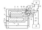
次に、本願発明の実施形態を図面に基づいて説明する。まず、図1,2の模式図を説明する。
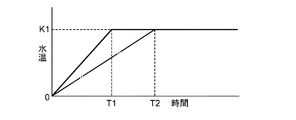
第1サーモ弁27が開き作動開始する温度は、従来と同様の例えば80℃程度に設定している。他方、第2サーモ弁28は、例えば70℃までの低温度領域では開弁していて、70℃に至ると閉弁するように設定している。従って、本実施形態では、70℃以下を低温度領域、70〜80℃を中温度領域、80℃以上を高温度領域として定義している。勿論、これは一例であり、低温・中温・高温の領域は任意に設定できる。
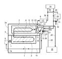
図4に示す第2実施形態では、変速用CVT装置のオイルを加温するCVTウォーマ29を備えている。CVTウォーマ29の入り口は、ヒータ送り管路24のうちEGRクーラ17よりも下流側の部位にCVTウォーマ送り管路30によって接続されており、CVTウォーマ29の出口は、ヒータ戻り管路24にCVTウォーマ送り管路30で接続されている。そして、CVTウォーマ送り管路30に、第3サーモ弁32を介在させている。
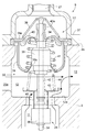
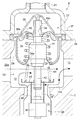
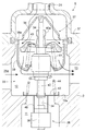
次に、第1サーモ弁27及びに一体化したサーモ弁装置の具体例を、図5以下の図面に基づいて説明する。なお、サーモ弁装置は、サーモ弁ユニットと呼ぶことも可能である。
本願発明は、上記の実施形態の他にも様々に具体化できる。
2 シリンダヘッド
3 ブロックジャケット
4 ヘッドジャケット
6 ウォータポンプ
8 冷却水制御装置
11 リーク通路
12 戻り中継室
14 メイン戻り管路
16 ラジエータ
17 EGRクーラ
18 ヒータ
20 ラジエータ送り管路
22 ラジエータ戻り管路
24 ヒータ送り管路
25 ヒータ戻り管路
27 第1サーモ弁(第1制御弁)
28 第2サーモ弁(第2制御弁)
33 サーモ弁装置
34 中心軸
35 第1スライダー
36 第2スライダー
40 第1弁体
41 第1ばね
43 第2弁体
44 第2ばね
Claims (1)
- シリンダヘッドに設けた冷却用のヘッドジャケットの出口に連通すると共にウォータポンプに至るメイン戻り管路が接続された戻り中継室を有しており、
前記戻り中継室に、ラジエータを通過した冷却水が流れるラジエータ戻り管路と、車内用ヒータを通過した冷却水が流れるヒータ戻り管路とが接続されていて、前記ラジエータ戻り管路から前記戻り中継室への通水は冷却水温度に基づいて作動する第1制御弁によって制御され、前記ヒータ戻り管路から戻った冷却水はそのままメイン戻り管路に流れるようになっており、
かつ、前記戻り中継室とヘッドジャケットとはリーク通路によって連通しており、前記第1制御弁の作動温度よりも低い温度域において冷却水を前記リーク通路から戻り中継室に通水させる第2制御弁を設けている構成であって、
前記第1制御弁と第2制御弁とは、それぞれ感温ワックスの膨張収縮の作用によって中心軸上を移動するスライダーを有していて、これら第1制御弁と第2制御弁の中心軸は同軸に共通化されており、
かつ、前記第2制御弁では、前記スライダーは前記リーク通路の内部に配置されて、弁体は前記戻り中継室に配置されている、
車両用内燃機関の冷却水制御装置。
Priority Applications (1)
| Application Number | Priority Date | Filing Date | Title |
|---|---|---|---|
| JP2015122882A JP6576702B2 (ja) | 2015-06-18 | 2015-06-18 | 車両用内燃機関の冷却水制御装置 |
Applications Claiming Priority (1)
| Application Number | Priority Date | Filing Date | Title |
|---|---|---|---|
| JP2015122882A JP6576702B2 (ja) | 2015-06-18 | 2015-06-18 | 車両用内燃機関の冷却水制御装置 |
Publications (2)
| Publication Number | Publication Date |
|---|---|
| JP2017008753A JP2017008753A (ja) | 2017-01-12 |
| JP6576702B2 true JP6576702B2 (ja) | 2019-09-18 |
Family
ID=57761049
Family Applications (1)
| Application Number | Title | Priority Date | Filing Date |
|---|---|---|---|
| JP2015122882A Active JP6576702B2 (ja) | 2015-06-18 | 2015-06-18 | 車両用内燃機関の冷却水制御装置 |
Country Status (1)
| Country | Link |
|---|---|
| JP (1) | JP6576702B2 (ja) |
Families Citing this family (3)
| Publication number | Priority date | Publication date | Assignee | Title |
|---|---|---|---|---|
| JP6604485B2 (ja) * | 2017-04-13 | 2019-11-13 | トヨタ自動車株式会社 | 内燃機関の冷却装置 |
| CN111886433B (zh) | 2018-03-14 | 2023-03-21 | 斯堪尼亚商用车有限公司 | 用于冷却系统的恒温器装置和包括所述恒温器装置的冷却系统 |
| CN110985188B (zh) * | 2019-12-11 | 2024-12-17 | 佛山市川东磁电股份有限公司 | 一种热敏磁控式节温器 |
Family Cites Families (3)
| Publication number | Priority date | Publication date | Assignee | Title |
|---|---|---|---|---|
| DE3347002C1 (de) * | 1983-12-24 | 1985-05-15 | Bayerische Motoren Werke AG, 8000 München | Temperaturregler-Einsatz fuer den Kuehlkreis fluessigkeitsgekuehlter Brennkraftmaschinen |
| JPS61101617A (ja) * | 1984-10-23 | 1986-05-20 | Nippon Thermostat Kk | 冷却水用サ−モスタツト |
| JP6174348B2 (ja) * | 2013-03-28 | 2017-08-02 | ダイハツ工業株式会社 | 車両用内燃機関 |
-
2015
- 2015-06-18 JP JP2015122882A patent/JP6576702B2/ja active Active
Also Published As
| Publication number | Publication date |
|---|---|
| JP2017008753A (ja) | 2017-01-12 |
Similar Documents
| Publication | Publication Date | Title |
|---|---|---|
| JP5227205B2 (ja) | 内燃機関の冷却装置 | |
| CN106437996B (zh) | 车辆热管理系统及其使用方法和车辆 | |
| KR101018538B1 (ko) | 차량의 냉각 장치 | |
| JP6201886B2 (ja) | 吸気冷却装置 | |
| US5497734A (en) | Cooling system for liquid-cooled engine | |
| JP6186506B2 (ja) | 車両冷却装置 | |
| JP6576702B2 (ja) | 車両用内燃機関の冷却水制御装置 | |
| JP6754705B2 (ja) | 内燃機関 | |
| CN216198425U (zh) | 一种发动机冷却系统和车辆 | |
| CN108361100A (zh) | 用于内燃机的冷却系统和恒温器装置 | |
| JP6257037B2 (ja) | サーモスタット装置 | |
| JP5668318B2 (ja) | 車両の冷却装置 | |
| JP2010121455A (ja) | 熱応動弁装置 | |
| CN109236450A (zh) | 一种发动机的冷却系统、控制方法及发动机 | |
| JP5494357B2 (ja) | 内燃機関の冷却装置 | |
| JP2014134102A (ja) | 車両用エンジンのサーモスタット装置 | |
| JP2014145326A (ja) | 内燃機関 | |
| JP2012184672A (ja) | 内燃機関の冷却装置 | |
| JP6634739B2 (ja) | エンジンの冷却装置 | |
| JP4539372B2 (ja) | エンジンの冷却装置 | |
| CN107975413B (zh) | 具有加热锅炉的内燃机冷却循环系统 | |
| JP2012197730A (ja) | エンジン | |
| JP6911363B2 (ja) | 内燃機関の冷却装置 | |
| KR101219693B1 (ko) | 실린더 헤드의 냉각수 라인 구조 | |
| JP5935476B2 (ja) | エンジンの冷却装置 |
Legal Events
| Date | Code | Title | Description |
|---|---|---|---|
| A621 | Written request for application examination |
Free format text: JAPANESE INTERMEDIATE CODE: A621 Effective date: 20180516 |
|
| A131 | Notification of reasons for refusal |
Free format text: JAPANESE INTERMEDIATE CODE: A131 Effective date: 20190220 |
|
| A977 | Report on retrieval |
Free format text: JAPANESE INTERMEDIATE CODE: A971007 Effective date: 20190221 |
|
| A521 | Request for written amendment filed |
Free format text: JAPANESE INTERMEDIATE CODE: A523 Effective date: 20190417 |
|
| A131 | Notification of reasons for refusal |
Free format text: JAPANESE INTERMEDIATE CODE: A131 Effective date: 20190508 |
|
| A521 | Request for written amendment filed |
Free format text: JAPANESE INTERMEDIATE CODE: A523 Effective date: 20190607 |
|
| TRDD | Decision of grant or rejection written | ||
| A01 | Written decision to grant a patent or to grant a registration (utility model) |
Free format text: JAPANESE INTERMEDIATE CODE: A01 Effective date: 20190807 |
|
| A61 | First payment of annual fees (during grant procedure) |
Free format text: JAPANESE INTERMEDIATE CODE: A61 Effective date: 20190821 |
|
| R150 | Certificate of patent or registration of utility model |
Ref document number: 6576702 Country of ref document: JP Free format text: JAPANESE INTERMEDIATE CODE: R150 |
|
| R250 | Receipt of annual fees |
Free format text: JAPANESE INTERMEDIATE CODE: R250 |
|
| R250 | Receipt of annual fees |
Free format text: JAPANESE INTERMEDIATE CODE: R250 |
|
| R250 | Receipt of annual fees |
Free format text: JAPANESE INTERMEDIATE CODE: R250 |