JP6528277B2 - vehicle - Google Patents
vehicle Download PDFInfo
- Publication number
- JP6528277B2 JP6528277B2 JP2015148822A JP2015148822A JP6528277B2 JP 6528277 B2 JP6528277 B2 JP 6528277B2 JP 2015148822 A JP2015148822 A JP 2015148822A JP 2015148822 A JP2015148822 A JP 2015148822A JP 6528277 B2 JP6528277 B2 JP 6528277B2
- Authority
- JP
- Japan
- Prior art keywords
- side wall
- vehicle
- width direction
- seat
- wall portion
- Prior art date
- Legal status (The legal status is an assumption and is not a legal conclusion. Google has not performed a legal analysis and makes no representation as to the accuracy of the status listed.)
- Active
Links
Images


Classifications
-
- B—PERFORMING OPERATIONS; TRANSPORTING
- B60—VEHICLES IN GENERAL
- B60N—SEATS SPECIALLY ADAPTED FOR VEHICLES; VEHICLE PASSENGER ACCOMMODATION NOT OTHERWISE PROVIDED FOR
- B60N2/00—Seats specially adapted for vehicles; Arrangement or mounting of seats in vehicles
- B60N2/005—Arrangement or mounting of seats in vehicles, e.g. dismountable auxiliary seats
- B60N2/01—Arrangement of seats relative to one another
- B60N2/012—The seat support being a part of the vehicle body or chassis
-
- B—PERFORMING OPERATIONS; TRANSPORTING
- B60—VEHICLES IN GENERAL
- B60N—SEATS SPECIALLY ADAPTED FOR VEHICLES; VEHICLE PASSENGER ACCOMMODATION NOT OTHERWISE PROVIDED FOR
- B60N2/00—Seats specially adapted for vehicles; Arrangement or mounting of seats in vehicles
- B60N2/005—Arrangement or mounting of seats in vehicles, e.g. dismountable auxiliary seats
- B60N2/015—Attaching seats directly to vehicle chassis
-
- B—PERFORMING OPERATIONS; TRANSPORTING
- B60—VEHICLES IN GENERAL
- B60N—SEATS SPECIALLY ADAPTED FOR VEHICLES; VEHICLE PASSENGER ACCOMMODATION NOT OTHERWISE PROVIDED FOR
- B60N2/00—Seats specially adapted for vehicles; Arrangement or mounting of seats in vehicles
- B60N2/24—Seats specially adapted for vehicles; Arrangement or mounting of seats in vehicles for particular purposes or particular vehicles
- B60N2/242—Bus seats
-
- B—PERFORMING OPERATIONS; TRANSPORTING
- B60—VEHICLES IN GENERAL
- B60N—SEATS SPECIALLY ADAPTED FOR VEHICLES; VEHICLE PASSENGER ACCOMMODATION NOT OTHERWISE PROVIDED FOR
- B60N2/00—Seats specially adapted for vehicles; Arrangement or mounting of seats in vehicles
- B60N2/24—Seats specially adapted for vehicles; Arrangement or mounting of seats in vehicles for particular purposes or particular vehicles
- B60N2/26—Seats specially adapted for vehicles; Arrangement or mounting of seats in vehicles for particular purposes or particular vehicles for children
- B60N2/28—Seats readily mountable on, and dismountable from, existing seats or other parts of the vehicle
- B60N2/283—Seats readily mountable on, and dismountable from, existing seats or other parts of the vehicle suspended
-
- B—PERFORMING OPERATIONS; TRANSPORTING
- B60—VEHICLES IN GENERAL
- B60N—SEATS SPECIALLY ADAPTED FOR VEHICLES; VEHICLE PASSENGER ACCOMMODATION NOT OTHERWISE PROVIDED FOR
- B60N2/00—Seats specially adapted for vehicles; Arrangement or mounting of seats in vehicles
- B60N2/24—Seats specially adapted for vehicles; Arrangement or mounting of seats in vehicles for particular purposes or particular vehicles
- B60N2/30—Non-dismountable or dismountable seats storable in a non-use position, e.g. foldable spare seats
- B60N2/3002—Non-dismountable or dismountable seats storable in a non-use position, e.g. foldable spare seats back-rest movements
- B60N2/3004—Non-dismountable or dismountable seats storable in a non-use position, e.g. foldable spare seats back-rest movements by rotation only
- B60N2/3009—Non-dismountable or dismountable seats storable in a non-use position, e.g. foldable spare seats back-rest movements by rotation only about transversal axis
- B60N2/3011—Non-dismountable or dismountable seats storable in a non-use position, e.g. foldable spare seats back-rest movements by rotation only about transversal axis the back-rest being hinged on the cushion, e.g. "portefeuille movement"
-
- B—PERFORMING OPERATIONS; TRANSPORTING
- B61—RAILWAYS
- B61B—RAILWAY SYSTEMS; EQUIPMENT THEREFOR NOT OTHERWISE PROVIDED FOR
- B61B9/00—Tramway or funicular systems with rigid track and cable traction
-
- B—PERFORMING OPERATIONS; TRANSPORTING
- B61—RAILWAYS
- B61D—BODY DETAILS OR KINDS OF RAILWAY VEHICLES
- B61D1/00—Carriages for ordinary railway passenger traffic
- B61D1/04—General arrangements of seats
-
- B—PERFORMING OPERATIONS; TRANSPORTING
- B61—RAILWAYS
- B61D—BODY DETAILS OR KINDS OF RAILWAY VEHICLES
- B61D17/00—Construction details of vehicle bodies
- B61D17/04—Construction details of vehicle bodies with bodies of metal; with composite, e.g. metal and wood body structures
- B61D17/043—Construction details of vehicle bodies with bodies of metal; with composite, e.g. metal and wood body structures connections between superstructure sub-units
-
- B—PERFORMING OPERATIONS; TRANSPORTING
- B61—RAILWAYS
- B61D—BODY DETAILS OR KINDS OF RAILWAY VEHICLES
- B61D19/00—Door arrangements specially adapted for rail vehicles
- B61D19/003—Door arrangements specially adapted for rail vehicles characterised by the movements of the door
- B61D19/005—Door arrangements specially adapted for rail vehicles characterised by the movements of the door sliding
-
- B—PERFORMING OPERATIONS; TRANSPORTING
- B61—RAILWAYS
- B61D—BODY DETAILS OR KINDS OF RAILWAY VEHICLES
- B61D33/00—Seats
-
- B—PERFORMING OPERATIONS; TRANSPORTING
- B61—RAILWAYS
- B61D—BODY DETAILS OR KINDS OF RAILWAY VEHICLES
- B61D33/00—Seats
- B61D33/0007—Details; Accessories
- B61D33/0014—Seat frames
-
- B—PERFORMING OPERATIONS; TRANSPORTING
- B61—RAILWAYS
- B61D—BODY DETAILS OR KINDS OF RAILWAY VEHICLES
- B61D33/00—Seats
- B61D33/0007—Details; Accessories
- B61D33/0035—Cushions or the like; Covers
-
- B—PERFORMING OPERATIONS; TRANSPORTING
- B61—RAILWAYS
- B61D—BODY DETAILS OR KINDS OF RAILWAY VEHICLES
- B61D33/00—Seats
- B61D33/0057—Seats characterised by their mounting in vehicles
- B61D33/0064—Seats characterised by their mounting in vehicles not adjustably mounted; supports therefor
-
- B—PERFORMING OPERATIONS; TRANSPORTING
- B61—RAILWAYS
- B61D—BODY DETAILS OR KINDS OF RAILWAY VEHICLES
- B61D33/00—Seats
- B61D33/0057—Seats characterised by their mounting in vehicles
- B61D33/0078—Seats characterised by their mounting in vehicles adjustably mounted
-
- B—PERFORMING OPERATIONS; TRANSPORTING
- B62—LAND VEHICLES FOR TRAVELLING OTHERWISE THAN ON RAILS
- B62D—MOTOR VEHICLES; TRAILERS
- B62D31/00—Superstructures for passenger vehicles
- B62D31/02—Superstructures for passenger vehicles for carrying large numbers of passengers, e.g. omnibus
- B62D31/025—Superstructures for passenger vehicles for carrying large numbers of passengers, e.g. omnibus having modular sections
-
- B—PERFORMING OPERATIONS; TRANSPORTING
- B61—RAILWAYS
- B61F—RAIL VEHICLE SUSPENSIONS, e.g. UNDERFRAMES, BOGIES OR ARRANGEMENTS OF WHEEL AXLES; RAIL VEHICLES FOR USE ON TRACKS OF DIFFERENT WIDTH; PREVENTING DERAILING OF RAIL VEHICLES; WHEEL GUARDS, OBSTRUCTION REMOVERS OR THE LIKE FOR RAIL VEHICLES
- B61F1/00—Underframes
- B61F1/08—Details
- B61F1/14—Attaching or supporting vehicle body-structure
Description
本発明は、車両に関する。 The present invention relates to a vehicle.
軌道に設けられたガイドレールによって案内されながら軌道上を走行する軌道系交通システム用の車両(新交通システム、AGT(Automated Guideway Transit)、又はAPM(Automated People Mover)と呼ばれる)や、その他の鉄道用の旅客車両、バス等の車両においては、車両の走行方向(前後方向)に対して側方に設けられた側壁部の内側に、車両の幅方向内方を向いて着座するシートが設けられることがある。特許文献1、2には、側壁部の車内側側面に背もたれを固定したシートが開示されている。
A vehicle for a track traffic system that travels on a track guided by a guide rail provided on the track (new traffic system, AGT (Automated Guideway Transit), or APM (Automated People Mover)), and other railways In a passenger vehicle, bus or other vehicle, a seat that faces inward in the width direction of the vehicle is provided inside a side wall provided laterally with respect to the traveling direction (longitudinal direction) of the vehicle. Sometimes.
上記したように、車両幅方向内方を向いて着座するシートを設ける場合、例えば車両の幅方向の最大寸法が制限されている場合や、シートの着座性を高めるために背もたれの高さや座部の前後方向の寸法を大きくした場合等には、車両幅方向両側のシートの間に形成される通路等のスペースが狭くなってしまう。その結果、通路に立った状態で乗車する乗客の快適性が損なわれたり、最大乗車人数が減少したりするといった問題がある。 As described above, when providing a seat that faces inward in the width direction of the vehicle, for example, when the maximum dimension in the width direction of the vehicle is limited, or to enhance the seating performance of the seat, the height and seat portion of the backrest When the dimension in the front-rear direction of the vehicle is increased, the space such as the passage formed between the seats on both sides in the vehicle width direction is narrowed. As a result, there is a problem that the comfort of the passenger riding in the state of standing in the aisle is impaired, and the maximum number of passengers decreases.
本発明は、上記事情に鑑みてなされたものであり、車両内のスペースの有効利用を図ることのできる車両を提供する。 The present invention has been made in view of the above circumstances, and provides a vehicle capable of effectively utilizing a space in the vehicle.
本発明は、上記課題を解決するため、以下の手段を採用する。
本発明の第一の態様では、車両は、箱状をなし、走行方向に直交する幅方向両側にそれぞれ側壁部を有するとともに、前記側壁部の上端部と下端部との間に前記上端部および前記下端部よりも幅方向外方に膨出した膨出部が形成された車両本体と、前記車両本体内に設けられ、前記側壁部に沿う背もたれ部、および前記背もたれ部から前記車両本体の幅方向内方に向かって延びる座面部を有し、前記背もたれ部の前記側壁部に対向する背面において最も前記側壁部側に突出する部分が、前記側壁部の車内側側面の前記膨出部に対向する位置に配置されたシートと、前記車両本体の前記側壁部の車外側側面に前記走行方向に沿って延びるよう設けられたドアレールと、前記側壁部の前記車外側側面よりも幅方向外方に設けられ、前記ドアレールに沿ってスライドする側引戸と、を備え、前記ドアレールは、前記膨出部よりも上方及び下方のうちの少なくとも一方に配置されるとともに、前記膨出部よりも前記車両本体の幅方向内方に設けられている。
The present invention adopts the following means in order to solve the above problems.
In the first aspect of the present invention, the vehicle has a box shape, and has side wall portions on both sides in the width direction orthogonal to the traveling direction, and the upper end portion between the upper end portion and the lower end portion of the side wall portion A vehicle body provided with a bulging portion bulging outward in the width direction than the lower end portion, a backrest portion along the side wall portion, and a width of the vehicle body from the backrest portion provided in the vehicle body A seat surface portion extending inward in the direction, and a portion of the back surface opposite to the side wall portion of the backrest that protrudes most toward the side wall portion faces the bulging portion of the inboard side surface of the side wall portion A seat disposed at a predetermined position, a door rail provided along the traveling direction on the outer side surface of the side wall portion of the vehicle body, and a width direction outward of the outer side surface of the side wall portion Provided, said door rail And a side sliding door that slides along the door rail is disposed in at least one of the upper and lower than the swollen portion, inward in the width direction of the vehicle body than the swollen portion It is provided .
このような構成によれば、シートの背もたれ部の背面において最も側壁部側に突出する部分が、側壁部の車内側側面において膨出部に対向する位置、すなわち車内側側面において最も幅方向外方に位置する部分に配置されている。これにより、シートを、車両幅方向外方側に最も寄せた位置に配置することができる。したがって、車両幅方向両側のシート間に形成される通路等のスペースを、最大限に広く確保することができる。
また、ドアレールおよび側引戸が側壁部の車外側側面の幅方向外方に設けられている場合、車両本体の車両限界の規制で、ドアレールおよび側引戸の幅方向の寸法分だけ側壁部を幅方向内方に設置する必要がある。この結果、車両本体の内部空間の幅方向寸法が小さくなってしまう。これに対し、ドアレールを、膨出部よりも上方(下方)に配置し、その下方(上方)に膨出部を配置することで、膨出部の部分において内部空間の幅寸法を大きくし、車両本体の内部空間の最大幅寸法を最大限大きくすることができる。
According to such a configuration, the portion of the back portion of the seat that protrudes most toward the side wall portion is the position where the side portion on the inner side of the side wall faces the bulging portion, that is, the outermost side in the width direction It is arranged in the part located in. Thus, the seat can be disposed at the position closest to the outer side in the vehicle width direction. Therefore, the space such as the passage formed between the seats on both sides in the vehicle width direction can be secured as wide as possible.
In addition, when the door rail and the side sliding door are provided outward in the width direction of the outer side surface of the side wall portion, the side wall portion in the width direction by the dimension of the door rail and the side sliding door in the width direction It needs to be installed inside. As a result, the dimension in the width direction of the internal space of the vehicle body is reduced. On the other hand, by arranging the door rail above (below) the bulging part and disposing the bulging part below (above), the width dimension of the internal space is increased at the bulging part, The maximum width dimension of the interior space of the vehicle body can be maximized.
本発明の第二の態様では、上記第一の態様において、前記シートは、前記側壁部に固定されて前記背もたれ部および前記座面部を支持するフレームを備え、前記フレームの上端部は、前記側壁部の前記車内側側面の前記膨出部に対向する前記位置よりも下方位置で前記側壁部に固定されていてもよい。 In a second aspect of the present invention, in the first aspect, the sheet includes a frame fixed to the side wall to support the backrest and the seat portion, and the upper end of the frame is the side wall It may be fixed to the side wall part in a lower position than the above-mentioned position which counters the above-mentioned bulging part of the above-mentioned inboard side of a part.
このように、フレームの上端部を側壁部の車内側側面の膨出部に対向する位置の下方位置で固定することで、膨出部にフレームを固定する場合と比較して、フレームを容易に側壁部に固定することができる。また、フレームの上端部を膨出部に対向する位置の下方位置で固定することで、例えば側壁部に窓を取り付ける場合、この窓の高さ方向の寸法を大きくすることができる。このため、車両本体の内部スペースの開放感等が増し、乗客の快適性向上につながるとともに、エクステリアのデザイン性の向上につながる。 In this manner, by fixing the upper end of the frame at a lower position of the side opposite to the bulge on the side surface on the side of the side of the side wall, the frame can be easily made as compared with fixing the frame to the bulge. It can be fixed to the side wall. Further, by fixing the upper end portion of the frame at a lower position opposite to the bulging portion, for example, in the case of attaching the window to the side wall portion, the dimension in the height direction of the window can be increased. As a result, the feeling of opening the interior space of the vehicle body is increased, which leads to the improvement of the passenger's comfort and the design of the exterior.
本発明の第三の態様では、上記第一又は第二の態様において、前記側壁部に、窓部が設けられ、前記背もたれ部の上端は、前記窓部の下縁よりも上方に突出していてもよい。 In the third aspect of the present invention, in the first or second aspect, the side wall portion is provided with a window portion, and the upper end of the backrest portion protrudes upward beyond the lower edge of the window portion. It is also good.
このように構成することで、シートを車両幅方向外方側に最も寄せた位置に装着しつつ、背もたれの上端を窓部の下縁よりも上方に突出させることで、背もたれの高さ方向の寸法を大きく確保することができ、着座時の快適性を高めることができる。さらに、窓部の下縁を背もたれ部の上端よりも下方に位置させることで、窓部の高さ方向の寸法を大きくすることができ、車両本体の内部スペースにおける開放感を高めることができ、エクステリアのデザイン性の向上にもつながる。 With this configuration, the seat is mounted at the position closest to the outer side in the vehicle width direction, and the upper end of the backrest protrudes upward beyond the lower edge of the window portion, whereby the height direction of the backrest is reduced. A large size can be secured, and comfort when sitting can be enhanced. Furthermore, by positioning the lower edge of the window portion below the upper end of the backrest portion, the size in the height direction of the window portion can be increased, and the feeling of opening in the internal space of the vehicle body can be enhanced. It also leads to an improvement in the design of the exterior.
本発明の第四の態様によれば、上記第一から第三の態様において、前記側壁部が前記上端部および前記下端部と前記膨出部とを直線状に結ぶことで、前記車両本体では、前記走行方向に直交する鉛直面内における断面形状が六角形状をなしていてもよい。
According to a fourth aspect of the present invention, in the vehicle body according to the first to third aspects, the side wall portion connects the upper end portion, the lower end portion, and the bulging portion in a straight line. The cross-sectional shape in the vertical plane orthogonal to the traveling direction may be hexagonal.
このように、側壁部に膨出部が設けられて車両本体の断面形状が六角形状をなすことで、シートを幅方向外方側に寄せて配置でき、車両幅方向両側のシート間に形成される通路等のスペースを、最大限に広く確保できる。また、車両本体の外観を特徴的なものとすることができる。 As described above, the bulging portion is provided in the side wall portion, and the cross section of the vehicle main body has a hexagonal shape, whereby the seat can be disposed close to the width direction outward side and formed between the seats on both sides in the vehicle width direction. Space such as aisle can be secured as wide as possible. In addition, the appearance of the vehicle body can be made distinctive.
本発明に係る車両によれば、通路等のスペースを最大限に広く確保することで、車両内のスペースの有効利用を図ることが可能となる。 According to the vehicle of the present invention, the space in the vehicle can be effectively used by securing the space such as the passage as wide as possible.
以下、本発明の実施形態に係る車両を図面に基づき説明する。
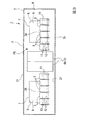
図1から図4に示すように、この実施形態の車両1は、例えば軌道系交通システムに用いられる。
車両1は、車両本体2と、車両本体2に設けられた扉部5(図2、図3参照)と、車両本体2内に設けられたシート3(図3、図4参照)と、を備えている。
Hereinafter, a vehicle according to an embodiment of the present invention will be described based on the drawings.
As shown in FIGS. 1 to 4, a
車両本体2は、箱状をなし、その内部が乗客を収容する客室PSとされた例えば中空の直方体形状をなしている。図1、図2に示すように、車両本体2の車内床面2fを形成するベース部2bの下方には、走行用の車輪4r、および軌道に沿って進行方向をガイドするガイド輪4gを備えた走行装置4が、車両本体2の長手方向の両端部にそれぞれ設けられている。
The
図1に示すように、車両本体2は、長手方向(車両1の走行方向)に交差する幅方向両側に設けられた側壁部6を有している。
側壁部6はそれぞれ、上端部6aおよび下端部6bと、上端部6aと下端部6bとの間の上下方向中間部に幅方向外方に膨出した膨出部6cとを有している。この実施形態において、側壁部6は、上端部6aと膨出部6cとの間、および膨出部6cと下端部6bとの間が、それぞれ平板状に形成されている。ここで、車両本体2の車両幅方向両側の側壁部6の膨出部6c間の幅寸法Wmが、車両本体2の車両最大幅寸法となる。
また、膨出部6cは、図5に示すように、ベース部2bの上面側の車内床面2fに対し、600mm以上1100mm以下、好ましくは700mm以上1000mm以下、より好ましくは800mm以上900mm以下の高さH1の範囲に配置するとよい。
As shown in FIG. 1, the
The
Further, as shown in FIG. 5, the bulging
また、図1に示すように、車両本体2のベース部2b、および車両本体2の天井面を形成するルーフ部2rはほぼ平板状とされている。そして本実施形態では、ベース部2b、ルーフ部2r、および側壁部6によって、車両本体2の前後方向に直交する鉛直面における断面形状が、略六角形状をなしている。
Further, as shown in FIG. 1, a
図2に示すように、扉部5は、車両本体2の幅方向両側の側壁部6にそれぞれ設けられている。扉部5は、車両本体2の側壁部6の幅方向外方を向く車外側側面6sの上部に、前後方向に延びるように設けられたドアレール5aと、ドアレール5aに吊下され、側壁部6の車外側側面6sの幅方向外方でドアレール5aに沿った方向にスライドすることで開閉可能とされた側引戸5bと、を備えている。
ここで、図1に示すように、ドアレール5aは、車両本体2の車両最大幅寸法となる側壁部6の膨出部6cよりも、車両幅方向外方に突出せずに、車両幅方向内方に設けられている。
なお、ドアレール5aは、膨出部6cよりも上方に設けられる場合だけでなく、膨出部6cよりも下方に設けられてもよい。また、膨出部6cよりも上方及び下方の両方に設けられてもよい。
As shown in FIG. 2, the
Here, as shown in FIG. 1, the
The
また、図2に示すように、閉じた状態の扉部5の側引戸5bと干渉しない位置で、車両本体2の幅方向両側の側壁部6には、窓部7が設けられている。図5に示すように、この窓部7は、側壁部6に形成された開口部8に嵌め込まれたガラス9を有している。ここで、窓部7は図5に示すように側壁部6において上下方向中間部の膨出部6cよりも上方に配置されている。
Further, as shown in FIG. 2,
図3、図4に示すように、シート3は、車両本体2内に複数設けられている。これら複数のシート3は車両本体の前後方向に隣り合うようにして並んで設けられることで、ロングシート3Aを構成している。ここで、シート3は単体で車両本体2の車内に設けられてもよい。
As shown in FIGS. 3 and 4, a plurality of
シート3は、車両1の側壁部6に車両幅方向内側を向いて設けられ、フレーム11と、座面部12と、背もたれ部13と、を備えている。
The
フレーム11は、車両本体2の長手方向に間隔を空けて複数配置されている。この実施形態において、フレーム11は、各シート3のシート幅方向(車両本体2における長手方向)両側にそれぞれ配置されている。
A plurality of
図5に示すように、各フレーム11は、車両本体2の車内床面2fの上方において、車両幅方向に延びる座面サポート部11aと、側壁部6の車両幅方向内側を向く車内側側面6tに沿って上下方向に延びる背面サポート部11bとを備えており、全体として略L字状をなしている。
As shown in FIG. 5, each
各フレーム11の背面サポート部11bの下端部には、下方に向かって車両幅方向内方に傾斜し、座面サポート部11aの一端11pに連結された接続アーム部11cが一体に形成されている。座面サポート部11aは、接続アーム部11cの下端に連結された一端11p側から、車両幅方向内方側の他端11qに向かって、漸次上方に延びるよう、傾斜している。
At the lower end portion of the
各フレーム11の背面サポート部11bの下端部には、鉛直下方に向かって突出する係止爪14が形成され、背面サポート部11bの上端部には、取付ボルト15が挿通されるボルト挿通孔16が形成されている。
The lower end portion of the rear
係止爪14は、側壁部6の車内側側面6tに形成された係止溝20に係止される。係止溝20は、下方に凹む凹状に形成されて車両本体2の長手方向に延びている。
The locking
ボルト挿通孔16に挿通された取付ボルト15は、側壁部6の車内側側面6tに形成された固定ベース21に取り付けられることで、フレーム11の背面サポート部11bの上端部11tを固定ベース21に突き当てた状態で固定する。ここで具体的な構造として、例えば、固定ベース21は、車両本体2の長手方向に延びるレールとなっており、このレールには長手方向の端部から取付ボルト15のボルト頭が挿入可能となっている。そして、取付ボルト15のネジ部分が幅方向に車内側に向かって突出するようにボルト頭がレールに挿入された状態で、ネジ部を背面サポート部11bの上端部11tにナット15aによって固定することで、フレーム11をレールを介して側壁部6に固定する。
固定ベース21は、側壁部6の車内側側面6tで、膨出部6cよりも所定寸法だけ下方に形成されている。
The mounting
The fixed
座面部12は、背もたれ部13の下端部から車両幅方向内方に向かって延びるように形成されている。座面部12は、フレーム11の座面サポート部11a上に配置された座面ベース板17と、座面ベース板17上に設けられた座面クッション18と、を備えている。
The
座面ベース板17は、車両本体2の長手方向に連続して形成され、車両本体2の長手方向に間隔を空けて配置された複数のフレーム11の座面サポート部11a上に跨がって設けられている。この座面ベース板17は、ボルト19によって、各フレーム11の座面サポート部11aに締結固定されている。
The
座面クッション18は、乗客一人分ずつ別体となっており、発泡ウレタン等の弾性材料から形成されている。座面クッション18は、座面ベース板17を上方から覆うように、座面ベース板17に引っかけ構造、またはボルト(図示無し)等によって固定されている。これにより座面クッション18の上面は、乗客が着座する着座面18sとなっている。
The
座面クッション18の車両幅方向内側の先端部18tは、座面サポート部11aの他端11qよりも車両幅方向内側に突出して設けられている。座面クッション18の前後方向(車両幅方向に一致する方向)の長さ寸法は、例えば500mm程度の寸法とされる。また、座面クッション18は背もたれ部13の下部に50mm程度入り込んだ状態で設けられている。
A
背もたれ部13は、乗客一人分ずつ別体となっており、フレーム11の背面サポート部11bを車両幅方向内側から覆うように設けられている。この背もたれ部13は、その上端部13tが、フレーム11の背面サポート部11bの上端部11t、側壁部6の膨出部6c、および窓部7の下縁7bの全てよりも上方に突出している。この背もたれ部13の上端部13tは、ベース部2bの上面側の車内床面2fに対し、700mm以上1200mm以下、好ましくは800mm以上1100mm以下、より好ましくは900mm以上1000mm以下の範囲の高さH2に設定するとよい。
The
また、背もたれ部13の上端部13tにおいて、側壁部6に対向する背面側において最も側壁部6側に突出する部分には、側壁部6の車内側側面6tにおいて膨出部6cに対応した部位6pに突き当たる当接部13pが設けられている。
背もたれ部13の上端部13t寄りの位置には、側壁部6に向かって突出するようにブラケット13aが設けられている。また、固定ベース21には、側壁部6から離間する方向に突出するようにブラケット21aが設けられている。例えばブラケット21aは、フレーム11と同様に、レールである固定ベース21にボルトとナットとによって固定される。そして、ブラケット13aがブラケット21aに上方から引っ掛かることで、背もたれ部13が側壁部6に固定されている。ブラケット13a及びブラケット21aが設けられる位置は、各背もたれ部13のシート幅方向の略中央の位置となっている。
また、背もたれ部13の下端部13bは、座面ベース板17にファスナー22によって固定されている。
Further, in the
A
Further, the
また、背もたれ部13は、発泡ウレタン等の弾性材料からなる。背もたれ部13は、車両1の高さ方向に対し、上方に向かって車両幅方向外方に、例えば15度傾斜しているとよい。即ち、トルソー角が15度となっているとよい。
The
上述したような車両1によれば、シート3の背もたれ部13の背面において最も側壁部6側に突出する部分である当接部13pが、側壁部6の車内側側面6tにおいて膨出部6cに対向する部位6pに対向するよう配置されている。これにより、シート3を車両幅方向外方側に最も寄せた位置に配置することができる。したがって、車両幅方向両側のシート3間に形成される通路等のスペースSを、最大限に広く確保することができ、車両本体2内の空間の有効利用を図ることが可能となる。
According to the
また、フレーム11の上端部11tを、側壁部6の車内側側面6tの膨出部6cに対向する部位6pの下方位置で固定することで、膨出部6cにフレーム11を固定する場合と比較してフレーム11を容易かつ確実に固定することができる。
In addition, by fixing the
さらに、背もたれ部13の上端部13tは、窓部7の下縁7bよりも上方に突出している。このように構成することで、シート3を車両幅方向外方側に最も寄せた位置に装着しつつも、背もたれ部13の高さを大きく確保して着座時の快適性を高めることができる。さらに、窓部7の下縁7bを背もたれ部13の上端部13tよりも下方に位置させることで、窓部7の高さ方向の寸法を大きくすることができ、車両本体2内の空間における開放感を高めることができる。さらに窓部7を大型化できることでエクステリアのデザイン性の向上にもつながる。
Furthermore, the
また、車両本体2の側壁部6において、幅方向外方を向く車外側側面6sに走行方向に沿って延びるドアレール5aが設けられ、側壁部6の車外側側面6sよりも幅方向外方にドアレール5aに沿ってスライドする側引戸5bが設けられている。そして、ドアレール5aは、膨出部6cよりも上方に配置されるとともに、膨出部6cよりも幅方向内方に設けられている。
Further, in the
ここで、ドアレール5aおよび側引戸5bを側壁部6の幅方向外方に設けると、一般的には、車両限界の規制により、車両本体2の側壁部6を車両幅方向内方に設置することが必要となる。この結果、車両本体2の内部空間の幅方向寸法が小さくなってしまう。これに対し、ドアレール5aの下方に膨出部6cを配置することで、車両本体2の内部空間の最大幅寸法を最大限大きくすることができる。
Here, when the
さらに、側壁部6は、上端部6aおよび下端部6bと膨出部6cとを直線状に結んでおり、車両本体2の断面形状が六角形状となっている。
このような構成によれば、シート3を幅方向外方側に寄せて配置することで、車両幅方向両側のシート3間に形成される通路等のスペースSを最大限に広く確保しつつ、車両本体2の外観を特徴的なものとすることができる。
Furthermore, the
According to such a configuration, by arranging the
なお、本発明は、上述した実施形態に限定されるものではなく、本発明の趣旨を逸脱しない範囲において、上述した実施形態に種々の変更を加えたものを含む。即ち、実施形態で挙げた具体的な形状や構成等は一例にすぎず、適宜変更が可能である。
例えば、上記実施形態では、側壁部6は、上端部6aと膨出部6cとの間、および膨出部6cと下端部6bとの間が、それぞれ平板状に形成されているが、これに限らない。側壁部6において膨出部6cが幅方向外方に最も突出しているのであれば、側壁部6は、例えば、断面湾曲形状としてもよい。また、車両本体2の断面形状は六角形に限定されず、例えば八角形等の多角形状をなしていてもよい。また、上述の実施形態では、車両本体2のベース部2b、および車両本体2の天井面を形成するルーフ部2rはほぼ平板状とされているが、これに限定されず、例えば湾曲板状や、屈曲板状をなしていてもよい。
The present invention is not limited to the above-described embodiment, and includes the above-described embodiment with various changes added thereto, without departing from the spirit of the present invention. That is, the specific shape, configuration, and the like described in the embodiment are merely examples, and can be changed as appropriate.
For example, in the above embodiment, the
また、扉部5は、側壁部6の幅方向内方を向く車内側側面6tに設けられていてもよい。
In addition, the
また、上述した実施形態、及び各変形例の構成は、適宜組み合わせてよい。 In addition, the configurations of the above-described embodiment and each modification may be combined as appropriate.
1 車両
2 車両本体
2b ベース部
2f 車内床面
2r ルーフ部
3 シート
3A ロングシート
4 走行装置
4g ガイド輪
4r 車輪
5 扉部
5a ドアレール
5b 側引戸
6 側壁部
6a 上端部
6b 下端部
6c 膨出部
6s 車外側側面
6t 車内側側面
6p 部位
7 窓部
7b 下縁
8 開口部
9 ガラス
11 フレーム
11a 座面サポート部
11b 背面サポート部
11c 接続アーム部
11p 一端
11q 他端
11t 上端部
12 座面部
13 背もたれ部
13a ブラケット
13b 下端部
13p 当接部
13t 上端部
14 係止爪
15 取付ボルト
15a ナット
16 ボルト挿通孔
17 座面ベース板
18 座面クッション
18s 着座面
18t 先端部
19 ボルト
20 係止溝
21 固定ベース
21a ブラケット
22 ファスナー
PS 客室
S スペース
DESCRIPTION OF
Claims (4)
前記車両本体内に設けられ、前記側壁部に沿う背もたれ部、および前記背もたれ部から前記車両本体の幅方向内方に向かって延びる座面部を有し、前記背もたれ部の前記側壁部に対向する背面において最も前記側壁部側に突出する部分が、前記側壁部の車内側側面の前記膨出部に対向する位置に配置されたシートと、
前記車両本体の前記側壁部の車外側側面に前記走行方向に沿って延びるよう設けられたドアレールと、
前記側壁部の前記車外側側面よりも幅方向外方に設けられ、前記ドアレールに沿ってスライドする側引戸と、
を備え、
前記ドアレールは、前記膨出部よりも上方及び下方のうちの少なくとも一方に配置されるとともに、前記膨出部よりも前記車両本体の幅方向内方に設けられている車両。 It has a box shape, and has side wall portions on both sides in the width direction orthogonal to the traveling direction, and bulges outward in the width direction more than the upper end portion and the lower end portion between the upper end portion and the lower end portion of the side wall portion A vehicle body in which a bulged portion is formed;
A backrest portion provided in the vehicle body, the seatback portion extending along the side wall portion, and a seat surface portion extending inward in the width direction of the vehicle body from the backrest portion, and a back surface facing the side wall portion of the backrest portion A sheet disposed at a position at which the portion most projecting toward the side wall portion faces the bulging portion on the inner side surface of the side wall portion;
A door rail provided along the traveling direction on an outer side surface of the side wall portion of the vehicle main body;
A side sliding door provided on the lateral side of the side wall portion outside in the width direction than the side surface outside the vehicle and sliding along the door rail;
Equipped with
The door rail is disposed in at least one of the upper and lower than the bulging section, that provided inward in the width direction of the vehicle body than the swollen portion vehicles.
前記フレームの上端部は、前記側壁部の車内側側面の前記膨出部に対向する前記位置よりも下方位置で前記側壁部に固定されている請求項1に記載の車両。 The seat includes a frame fixed to the side wall and supporting the backrest and the seat.
2. The vehicle according to claim 1, wherein the upper end portion of the frame is fixed to the side wall portion at a position lower than the position facing the bulging portion on the inward side surface of the side wall portion.
前記背もたれ部の上端は、前記窓部の下縁よりも上方に突出している請求項1又は2に記載の車両。 A window is provided on the side wall,
The upper end of the backrest of the vehicle according to claim 1 or 2 protrudes upward from the lower edge of the window.
Priority Applications (6)
| Application Number | Priority Date | Filing Date | Title |
|---|---|---|---|
| JP2015148822A JP6528277B2 (en) | 2015-07-28 | 2015-07-28 | vehicle |
| PCT/JP2016/071014 WO2017018251A1 (en) | 2015-07-28 | 2016-07-15 | Vehicle |
| KR1020177035760A KR102005171B1 (en) | 2015-07-28 | 2016-07-15 | vehicle |
| CN201680035175.3A CN107709129B (en) | 2015-07-28 | 2016-07-15 | Vehicle with a steering wheel |
| EP16830356.8A EP3287336B1 (en) | 2015-07-28 | 2016-07-15 | Vehicle |
| US15/574,680 US10696188B2 (en) | 2015-07-28 | 2016-07-15 | Vehicle |
Applications Claiming Priority (1)
| Application Number | Priority Date | Filing Date | Title |
|---|---|---|---|
| JP2015148822A JP6528277B2 (en) | 2015-07-28 | 2015-07-28 | vehicle |
Publications (3)
| Publication Number | Publication Date |
|---|---|
| JP2017024692A JP2017024692A (en) | 2017-02-02 |
| JP2017024692A5 JP2017024692A5 (en) | 2018-06-21 |
| JP6528277B2 true JP6528277B2 (en) | 2019-06-12 |
Family
ID=57884511
Family Applications (1)
| Application Number | Title | Priority Date | Filing Date |
|---|---|---|---|
| JP2015148822A Active JP6528277B2 (en) | 2015-07-28 | 2015-07-28 | vehicle |
Country Status (6)
| Country | Link |
|---|---|
| US (1) | US10696188B2 (en) |
| EP (1) | EP3287336B1 (en) |
| JP (1) | JP6528277B2 (en) |
| KR (1) | KR102005171B1 (en) |
| CN (1) | CN107709129B (en) |
| WO (1) | WO2017018251A1 (en) |
Families Citing this family (3)
| Publication number | Priority date | Publication date | Assignee | Title |
|---|---|---|---|---|
| US10239425B2 (en) * | 2017-06-16 | 2019-03-26 | GM Global Technology Operations LLC | Movable partition system for a vehicle with stowable jumpseat |
| IT201800004098A1 (en) * | 2018-03-29 | 2019-09-29 | Iveco France Sas | BACKREST FOR VEHICLE |
| CN113320558B (en) * | 2021-06-10 | 2023-01-24 | 中车唐山机车车辆有限公司 | Carriage and rail vehicle |
Family Cites Families (23)
| Publication number | Priority date | Publication date | Assignee | Title |
|---|---|---|---|---|
| GB191505437A (en) | 1915-04-10 | 1915-09-02 | William Edward Constable | Improvements in and relating to Sliding Doors for Railway Cars and other Structures. |
| US1768060A (en) | 1925-08-06 | 1930-06-24 | Camel Co | Door |
| US4061089A (en) * | 1975-09-02 | 1977-12-06 | Elbert Morgan Sawyer | Personal rapid transit system |
| FR2736751B1 (en) | 1995-07-12 | 1997-08-14 | Gec Alsthom T & D Sa | DEVICE FOR ACTUATING AN ELECTRICAL APPARATUS IN PARTICULAR A HIGH VOLTAGE SWITCH OR EARTH SWITCH |
| JP3431772B2 (en) * | 1996-08-27 | 2003-07-28 | 天龍工業株式会社 | Vehicle seat arrangement switching device |
| AT410819B (en) | 2000-08-31 | 2003-08-25 | Siemens Sgp Verkehrstech Gmbh | DOOR MOUNTING |
| JP2002205641A (en) | 2001-01-11 | 2002-07-23 | Nippon Sharyo Seizo Kaisha Ltd | Seat structure for rolling stock |
| FR2822765B1 (en) | 2001-03-29 | 2003-06-27 | Regie Autonome Transports | SEAT ASSEMBLY FOR PUBLIC TRANSPORT VEHICLE |
| US6685254B2 (en) * | 2002-05-13 | 2004-02-03 | J. Bruce Emmons | Low floor mass transit vehicle |
| US20050098060A1 (en) | 2003-03-25 | 2005-05-12 | Dte Rail Services, Inc. | Trolley system for a railway boxcar door |
| JP5020548B2 (en) | 2006-06-06 | 2012-09-05 | シロキ工業株式会社 | Seat seat structure |
| JP2010221933A (en) * | 2009-03-25 | 2010-10-07 | Sumie Kogyo Kk | Seat structure |
| US8579350B2 (en) * | 2009-12-14 | 2013-11-12 | Kustom Seating Unlimited, Ltd. | Modular transit system |
| JP2011213226A (en) * | 2010-03-31 | 2011-10-27 | Hitachi Ltd | Railway vehicle |
| CN103635371B (en) * | 2011-02-17 | 2016-09-21 | 东日本旅客铁道株式会社 | Rail truck |
| ITTO20110579A1 (en) * | 2011-06-30 | 2012-12-31 | Maio Francesco Paolo Di | GROUP OF DOORS FOR RAIL VEHICLES, IN PARTICULAR FOR METROPOLITAN TRAINS |
| JP5871586B2 (en) * | 2011-11-24 | 2016-03-01 | 三菱重工業株式会社 | CONNECTED BODY, VEHICLE COMPRISING BODY AND MANUFACTURING METHOD |
| CN202827227U (en) | 2012-08-30 | 2013-03-27 | 中国北车集团大连机车车辆有限公司 | Stainless steel vehicle seat skeleton structure |
| JP6062692B2 (en) | 2012-09-13 | 2017-01-18 | 公益財団法人鉄道総合技術研究所 | Railcar body |
| JP6211341B2 (en) * | 2013-08-08 | 2017-10-11 | 近畿車輌株式会社 | Railway vehicle |
| CN203460871U (en) | 2013-08-23 | 2014-03-05 | 长春轨道客车股份有限公司 | A-type vehicle interior decoration system with nine-person seat |
| CN104527686B (en) * | 2014-11-26 | 2017-01-04 | 中车南京浦镇车辆有限公司 | Rail vehicle longitudinal direction seat |
| CN204296737U (en) | 2014-12-04 | 2015-04-29 | 长春轨道客车股份有限公司 | A kind of tip-up set structure |
-
2015
- 2015-07-28 JP JP2015148822A patent/JP6528277B2/en active Active
-
2016
- 2016-07-15 US US15/574,680 patent/US10696188B2/en active Active
- 2016-07-15 WO PCT/JP2016/071014 patent/WO2017018251A1/en active Application Filing
- 2016-07-15 CN CN201680035175.3A patent/CN107709129B/en active Active
- 2016-07-15 EP EP16830356.8A patent/EP3287336B1/en active Active
- 2016-07-15 KR KR1020177035760A patent/KR102005171B1/en active IP Right Grant
Also Published As
| Publication number | Publication date |
|---|---|
| CN107709129A (en) | 2018-02-16 |
| CN107709129B (en) | 2020-01-14 |
| EP3287336B1 (en) | 2019-09-11 |
| JP2017024692A (en) | 2017-02-02 |
| KR20180008580A (en) | 2018-01-24 |
| US10696188B2 (en) | 2020-06-30 |
| EP3287336A1 (en) | 2018-02-28 |
| KR102005171B1 (en) | 2019-07-29 |
| EP3287336A4 (en) | 2018-04-25 |
| US20180126874A1 (en) | 2018-05-10 |
| WO2017018251A1 (en) | 2017-02-02 |
Similar Documents
| Publication | Publication Date | Title |
|---|---|---|
| CN101920668B (en) | Vehicle seat | |
| US8708387B2 (en) | Console box | |
| JP6528277B2 (en) | vehicle | |
| WO2014189033A1 (en) | Monitor-equipped illumination device for vehicle | |
| CN106604850A (en) | Automobile steering wheel | |
| US20210261171A1 (en) | Driver's compartment for an interoperable rail vehicle | |
| JP5607134B2 (en) | Pet partition | |
| JP2017024692A5 (en) | ||
| JP2009202729A (en) | Railroad vehicle | |
| JP2008302911A (en) | Vehicle body structure | |
| US11180053B2 (en) | Longitudinal adjuster and vehicle seat | |
| US9873398B2 (en) | Vehicle interior structure | |
| JP2015019804A (en) | Seat assembly | |
| JP6357135B2 (en) | Railway vehicle | |
| JP5771499B2 (en) | Railway vehicle | |
| JP6542018B2 (en) | Seat unit | |
| JP7182081B2 (en) | vehicle cab structure | |
| KR200249828Y1 (en) | Headrest for passenger of erectric vehicle | |
| ES2826432T3 (en) | Rail vehicle with wall-type separating device | |
| KR20080054990A (en) | Center floor reinforcing structure in vehicle | |
| JP2010149756A (en) | Seat attachment structure | |
| US9944179B2 (en) | Center console | |
| JP6641616B2 (en) | Undercarriage structure | |
| CN116331366A (en) | Locomotive and tractor | |
| JP2019064374A (en) | Railway vehicle body structure |
Legal Events
| Date | Code | Title | Description |
|---|---|---|---|
| A711 | Notification of change in applicant |
Free format text: JAPANESE INTERMEDIATE CODE: A712 Effective date: 20180323 |
|
| A521 | Request for written amendment filed |
Free format text: JAPANESE INTERMEDIATE CODE: A523 Effective date: 20180511 |
|
| A621 | Written request for application examination |
Free format text: JAPANESE INTERMEDIATE CODE: A621 Effective date: 20180511 |
|
| TRDD | Decision of grant or rejection written | ||
| A01 | Written decision to grant a patent or to grant a registration (utility model) |
Free format text: JAPANESE INTERMEDIATE CODE: A01 Effective date: 20190416 |
|
| A61 | First payment of annual fees (during grant procedure) |
Free format text: JAPANESE INTERMEDIATE CODE: A61 Effective date: 20190425 |
|
| R150 | Certificate of patent or registration of utility model |
Ref document number: 6528277 Country of ref document: JP Free format text: JAPANESE INTERMEDIATE CODE: R150 |
|
| S533 | Written request for registration of change of name |
Free format text: JAPANESE INTERMEDIATE CODE: R313533 |
|
| R350 | Written notification of registration of transfer |
Free format text: JAPANESE INTERMEDIATE CODE: R350 |
|
| S111 | Request for change of ownership or part of ownership |
Free format text: JAPANESE INTERMEDIATE CODE: R313111 |
|
| R350 | Written notification of registration of transfer |
Free format text: JAPANESE INTERMEDIATE CODE: R350 |