JP6357135B2 - Railway vehicle - Google Patents
Railway vehicle Download PDFInfo
- Publication number
- JP6357135B2 JP6357135B2 JP2015139443A JP2015139443A JP6357135B2 JP 6357135 B2 JP6357135 B2 JP 6357135B2 JP 2015139443 A JP2015139443 A JP 2015139443A JP 2015139443 A JP2015139443 A JP 2015139443A JP 6357135 B2 JP6357135 B2 JP 6357135B2
- Authority
- JP
- Japan
- Prior art keywords
- buffer member
- sleeve partition
- seat
- sleeve
- disposed
- Prior art date
- Legal status (The legal status is an assumption and is not a legal conclusion. Google has not performed a legal analysis and makes no representation as to the accuracy of the status listed.)
- Active
Links
- 238000005192 partition Methods 0.000 claims description 112
- 125000002066 L-histidyl group Chemical group [H]N1C([H])=NC(C([H])([H])[C@](C(=O)[*])([H])N([H])[H])=C1[H] 0.000 description 14
- 238000009434 installation Methods 0.000 description 3
- 238000013459 approach Methods 0.000 description 2
- 230000000694 effects Effects 0.000 description 1
- 239000004744 fabric Substances 0.000 description 1
- 238000000034 method Methods 0.000 description 1
- 238000012986 modification Methods 0.000 description 1
- 230000004048 modification Effects 0.000 description 1
Images


Description
本発明は、鉄道車両に関する。 The present invention relates to a railway vehicle.
鉄道車両内には、側構体の長手方向に沿ってロングシート(座席)が配置されている。ロングシートの上方には側窓が配置されて、ロングシートの両端部にはそれぞれ袖仕切りが配置されている。2つの袖仕切りは、側窓を挟むように、側壁に垂直に固定されている。2つの袖仕切りの隣には、それぞれドア開口が形成されている(特許文献1の図1及び図2参照)。 A long seat (seat) is disposed in the railcar along the longitudinal direction of the side structure. Side windows are disposed above the long sheet, and sleeve partitions are disposed at both ends of the long sheet. The two sleeve partitions are fixed vertically to the side wall so as to sandwich the side window. Next to the two sleeve partitions, door openings are respectively formed (see FIGS. 1 and 2 of Patent Document 1).
近年、車両内の混雑を防ぐため、ロングシートの長さを短くし、ロングシートの両隣のスペースを広くした構造が提案されている。しかし、ロングシートを短くすると、ロングシートの長さが側窓の長さより短くなることがある。この場合、ロングシートの両端部の上方に側窓が配置されるため、ロングシートの両端部に配置された袖仕切りの端面の上部が側窓と対向する。側窓と対向した部分を側窓に固定することはできないため、袖仕切りは、上部が固定されていない不安定な状態で配置される。また、袖仕切りの端面と側窓とが対向して配置されると、袖仕切りにより側窓の設置及び交換に支障が生じる。 In recent years, in order to prevent congestion in the vehicle, a structure has been proposed in which the length of the long seat is shortened and the space on both sides of the long seat is widened. However, when the long sheet is shortened, the length of the long sheet may be shorter than the length of the side window. In this case, since the side windows are disposed above both ends of the long sheet, the upper portions of the end faces of the sleeve partitions disposed at both ends of the long sheet face the side windows. Since the part facing the side window cannot be fixed to the side window, the sleeve partition is arranged in an unstable state in which the upper part is not fixed. Further, when the end face of the sleeve partition and the side window are disposed to face each other, the sleeve partition causes troubles in installation and replacement of the side window.
さらに、車両内で乗客が快適に過ごせるようにするためには、ロングシートの両隣のスペースを広くすることに加え、さらなる改善が望まれる。 Furthermore, in order to allow passengers to spend comfortably in the vehicle, in addition to widening the space on both sides of the long seat, further improvement is desired.
そこで、本発明の目的は、ロングシートを従来より短くした場合でも、袖仕切りを安定して固定できるとともに、乗客が快適に過ごすことができる鉄道車両を提供することである。 Therefore, an object of the present invention is to provide a railway vehicle that can stably fix a sleeve partition and allow passengers to spend comfortably even when a long seat is made shorter than before.
本発明の鉄道車両は、ドアが配置される複数の開口が形成された側構体と、前記側構体の長手方向に沿って配置された複数の座席とを備え、前記開口と前記座席とが前記側構体の長手方向に交互に離れて配置され、前記側構体には、長手方向に隣り合う2つの前記開口の間に窓が配置され、長手方向に隣り合う2つの前記開口の間に配置された前記窓と前記座席において、長手方向に、前記窓の端部が前記座席の端部より前記開口に近い位置に配置されるとともに、その開口と前記座席との間に、前記座席の端部の一部に接するように板状の袖仕切りが配置され、前記側構体の内側に配置された側壁において前記袖仕切りとその袖仕切りに最も近い前記開口との間にある壁部と、その袖仕切りとのなす角が鈍角である。 The railway vehicle of the present invention includes a side structure formed with a plurality of openings in which doors are arranged, and a plurality of seats arranged along a longitudinal direction of the side structure, wherein the openings and the seats are The side structure is disposed alternately apart in the longitudinal direction, and the side structure is provided with a window between the two openings adjacent in the longitudinal direction and between the two openings adjacent in the longitudinal direction. was in the window and the seat, in the longitudinal direction, Rutotomoni end of the window is located at a position closer to the opening than the end portions of the seat, between the opening and the seat, an end portion of the seat A plate-like sleeve partition is disposed so as to be in contact with a part of the side wall, a wall portion disposed between the sleeve partition and the opening closest to the sleeve partition on the side wall disposed inside the side structure, and the sleeve The angle formed by the partition is an obtuse angle.
上記構成では、袖仕切りが側壁に近付くにつれて窓(側窓)から離れるように傾斜して配置されることにより、袖仕切りの端部を上端から下端まで側壁に対向するように配置することができる。これにより、袖仕切りの端部全体を側壁に固定することができる。また、袖仕切りの端部が窓と対向しないため、窓の設置及び交換に支障が生じない。さらに、袖仕切りが傾斜して配置されるため、座席端部と袖仕切りとの間にスペースが形成される。座席端部に座った乗客はこのスペースに肩や肘を配置できる。また、このスペースにより座客の肩が配置されるスペースが広がるため、乗客が余裕をもって座ることができる。
また、前記袖仕切りには、その袖仕切りに最も近い前記開口に近い面に第1緩衝部材が取り付けられ、前記袖仕切りとその袖仕切りに最も近い前記開口との間に、前記側壁に沿って、第2緩衝部材が配置され、前記第1緩衝部材及び前記第2緩衝部材は、前記座席の座部より高い位置に配置されていることが好ましい。
袖仕切りが傾斜していることにより、袖仕切りの第1緩衝部材にもたれ掛かった乗客と、壁部の第2緩衝部材にもたれ掛かった乗客とが干渉しにくくなるとともに、干渉を避ける方向へ移動する自由度が広がる。
したがって、座客と立客を含めた全ての乗客が快適に過ごすことができる。
In the said structure, it can arrange | position so that the edge part of a sleeve partition may be opposed to a side wall from an upper end to a lower end by inclining and arrange | positioning so that it may leave | separate from a window (side window) as a sleeve partition approaches a side wall. . Thereby, the whole edge part of a sleeve partition can be fixed to a side wall. Moreover, since the edge part of a sleeve partition does not oppose a window, a trouble does not arise in installation and replacement | exchange of a window. Furthermore, since the sleeve partition is inclined, a space is formed between the seat end and the sleeve partition. Passengers sitting at the end of the seat can place shoulders and elbows in this space. Moreover, since the space where a passenger's shoulder is arrange | positioned by this space spreads, a passenger can sit with a margin.
In addition, a first buffer member is attached to the sleeve partition on a surface near the opening that is closest to the sleeve partition, and along the side wall between the sleeve partition and the opening that is closest to the sleeve partition. It is preferable that a second buffer member is disposed, and the first buffer member and the second buffer member are disposed at a position higher than a seat portion of the seat.
Because the sleeve divider is inclined, the passenger leaning on the first cushioning member of the sleeve divider and the passenger leaning on the second cushioning member of the wall portion are less likely to interfere and move in a direction to avoid interference. More freedom to do so.
Therefore, all passengers including seats and guests can spend comfortably.
また、上記構成において、客室の平面視において、前記座席と前記袖仕切りとに挟まれた空間に、肘置きが配置されていることが好ましい。 In the above structure, in a plan view of the guest room, the sandwiched between the seat and the sleeve partition space, it is preferable that the elbow rest is located.
座席端部に座った乗客が、肘置きに肘を置くことができるため、楽に過ごすことができる。 Passengers sitting at the end of the seat can put their elbows on the elbow rest, so they can spend time comfortably.
さらに、上記構成において、前記袖仕切りと前記肘置きが一体であることが好ましい。 Furthermore, in the said structure, it is preferable that the said sleeve partition and the said elbow rest are integral.
これにより、車両内の部品点数を低減できるとともに、座席と袖仕切りの設置を簡易に行うことができる。 Thereby, while being able to reduce the number of parts in a vehicle, a seat and a sleeve partition can be installed simply.
また、上記構成において、前記壁部に沿って延在した板状の延在部材をさらに備え、前記袖仕切りと前記延在部材とが一体成型され、前記延在部材に前記第2緩衝部材が取り付けられていることが好ましい。 Further, in the above-described configuration, a plate-like extending member extending along the wall portion is further provided, the sleeve partition and the extending member are integrally formed, and the second buffer member is provided on the extending member. It is preferable that it is attached.
上記構成では、一体となった袖仕切りと延在部材に第1緩衝部材と第2緩衝部材が取り付けられているため、見栄えがよい。また、第2緩衝部材を延在部材に固定することにより、第2緩衝部材を安定して固定することができる。 In the said structure, since the 1st buffer member and the 2nd buffer member are attached to the sleeve partition and extension member which were united, it looks good. In addition, the second buffer member can be stably fixed by fixing the second buffer member to the extending member.
本発明によると、袖仕切りを安定して固定できるとともに、乗客が快適に過ごすことができる。 According to this invention, while being able to fix a sleeve partition stably, a passenger can spend comfortably.
以下、本発明の好適な実施形態について、図面を参照しつつ説明する。ここでは、本発明の第1実施形態である鉄道車両について、図1〜図4を参照しつつ以下に説明する。 Hereinafter, preferred embodiments of the present invention will be described with reference to the drawings. Here, the rail vehicle which is 1st Embodiment of this invention is demonstrated below, referring FIGS. 1-4.
〔第1実施形態〕
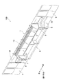
鉄道車両100には、図1に示すように、側構体1の長手方向に沿って座席(ロングシート)2が配置されている。側構体1には、座席2の上方に窓(側窓)3が配置されている。座席2の左側には少し離れた位置にドア4が配置されている。ドア4は、側構体1に形成されたドア開口(開口)14に配置されている。座席2の右側には少し離れた位置にドア5が配置されている。ドア5は、側構体1に形成されたドア開口(開口)15に配置されている。ドア開口と座席は、車両の長手方向(側構体1の長手方向)に交互に離れて配置されている。
[First Embodiment]
The
座席2は、既存のロングシートよりやや短い。座席2は窓3より車両長手方向(側構体1の長手方向)にやや短い。図中の左端部において、窓3の左端部が座席2の左端部よりドア開口14に近い。また、図中の右端部においても、窓3の右端部が座席2の右端部よりドア開口15に近い。
The
座席2の右端部には板状の袖仕切り6が配置されている。座席2の左端部には板状の袖仕切り7が配置されている。袖仕切り6及び袖仕切り7は座席2の先端部に接するように配置されている。また、座席2の左右両側において、握り棒8及び握り棒9がそれぞれ荷棚10から袖仕切り6及び袖仕切り7まで延在している。
A plate-
図1において座席2の右端部と左端部は同様な構成であるため、以下では、図2〜図4を参照しつつ、座席2の右端部について説明し、左端部の説明を省略する。また、図2に示すように、側構体1の内側に配置された側壁11のうち、袖仕切り6とドア開口15との間にある部分(図中の袖仕切り6の右側の部分)を第1壁部(壁部)12と称し、袖仕切り6より座席2側に配置された部分(図中の袖仕切り6の左側の部分)を第2壁部13と称することがある。
Since the right end portion and the left end portion of the
袖仕切り6は、図2及び図3に示すように、側壁11に近付くにつれて座席2から遠ざかるように傾斜している。袖仕切り6と第1壁部12とのなす角θは、鈍角となっている(図4(a)参照)。
As shown in FIGS. 2 and 3, the
袖仕切り6の先端部6Tは、座席2の腰掛2Aの先端部に接している。袖仕切り6の先端部6Tを除く部分は、座席2に接していない。
The
袖仕切り6を、従来のように、座席2の端部に沿って側壁11に垂直に配置すると(図4(b)参照)、袖仕切り6の後端面6Bの上部が窓3に対向する。窓3に対向した部分を窓3に固定することはできない。しかし、本実施形態では、袖仕切り6の後端面6Bを傾斜させているため、袖仕切り6の後端面6Bが窓3に対向しない(図3及び図4(a)参照)。袖仕切り6の後端面6Bは、上端から下端まで側壁11に対向し、後端面6Bの全面が側壁11に固定されている。
When the
袖仕切り6が傾斜していることにより、袖仕切り6と座席2との間にスペースSが形成されている。スペースSは、座席2と袖仕切り6と第2壁部13とに囲まれたスペースであり、客室の平面視において三角形状に形成されている(図4(b)参照)。スペースSには、図3に示すように、肘置き20が配置されている。肘置き20は、三角錘状に形成され、座席2の背もたれ2Bの上端と腰掛2Aとの中間付近の高さに配置されている。座席2の端部に座った乗客は、肘置き20に肘を載せることができる。肘置き20は袖仕切り6と一体になっていてもよい。
Since the
図2に戻って、袖仕切り6には、ドア開口15に近い第1面6F1と、座席2に近い第2面6F2とを有している。第1面6F1から第1壁部12にかけて、2つの緩衝部材(上緩衝部材30と下緩衝部材40)が上下方向に離れて配置されている。上緩衝部材と下緩衝部材は鈍角のV字状に形成され、いずれも腰掛2Aより上方に配置されている。上緩衝部材30の上端は、袖仕切り6の上端と同じ高さに配置されている。
Returning to FIG. 2, the
上緩衝部材30は、第1面6F1に取り付けられた横長状の第1緩衝部材31と、第1壁部12に取り付けられた横長状の第2緩衝部材32とを有している。第1緩衝部材31及び第2緩衝部材32は同じ高さに配置され、連続している。また、下緩衝部材40も、上緩衝部材30と同様に、第1面6F1に取り付けられた第1緩衝部材41と、第1壁部12に取り付けられた第2緩衝部材42とを有している。第1緩衝部材41及び第2緩衝部材42は同じ高さに配置され、連続している。上緩衝部材30と下緩衝部材40は、同様な形状である。
The
上緩衝部材30及び下緩衝部材40は、例えば、クッション性を有する生地を袖仕切り6や第1壁部12に上貼りしたり、クッション等の詰め物を配置したりすることにより形成されている。
The
袖仕切り6と、袖仕切り6に取り付けられた上緩衝部材30の第1緩衝部材31及び下緩衝部材40の第1緩衝部材41は、側壁11から離れるにつれて、ドア開口15から遠ざかるように配置されている。これにより、ドア開口15から車両に乗った乗客は、袖仕切り6と第1壁部12との間にあるスペースが広く感じられる。このため、側壁11の前に乗客が立っていても、袖仕切り6の前に移動しやすい。また、袖仕切り6が側壁11に対して垂直でなく、傾斜しているため、第1壁部12の前に立った乗客と袖仕切りの前に立った乗客の軸線(目線)が交差しない。このため、第1壁部12の前に立った乗客と袖仕切りの前に立った乗客が過ごしやすい。
The
袖仕切り6の前に立った乗客は、下緩衝部材40の第1緩衝部材41に腰を当てたり、手を置いたりすることができる。また、上緩衝部材30の第1緩衝部材31に肩を当てたり、肘を置いたりすることができる。
A passenger standing in front of the
第1壁部12の前に立った乗客は、下緩衝部材40の第2緩衝部材42に腰を当てたり、手を置いたりすることができる。また、上緩衝部材30の第2緩衝部材32に肩を当てたり、肘を置いたりすることができる。
A passenger standing in front of the
以上に述べたように、本実施形態の鉄道車両によると以下の効果を奏する。
座席2の長さが窓(側窓)3の長さより短いため、従来のように、袖仕切り6を座席2の端部に沿って側壁11に垂直に配置すると、袖仕切り6の後端面6Bが窓3に対向するが(図4(b)参照)、本実施形態では、袖仕切り6を窓3から離れるように傾斜させ、袖仕切り6と第1壁部12とのなす角θが鈍角をなすようにしている(図4(a)参照)。これにより、袖仕切り6の後端面6Bが上端から下端までを側壁に対向するようにできるため、後端面6B全体を側壁11に固定することができる。また、袖仕切り6と窓3が対向しないため、窓3の設置及び交換に支障が生じない。
As described above, the railway vehicle according to the present embodiment has the following effects.
Since the length of the
さらに、袖仕切り6が傾斜して配置されるため、座席2の端部と袖仕切り6との間にスペースSが形成される(図3参照)。座席2の端部に座った乗客はこのスペースに肩や肘を配置できる。また、スペースSにより座客の肩が配置されるスペースが広がるため、乗客が余裕をもって座ることができる。
Furthermore, since the
さらに、袖仕切り6が側壁11から離れるにつれてドア開口15から遠ざかるように傾斜しているため、第1緩衝部材31や第1緩衝部材41にもたれ掛かった乗客と、第2緩衝部材32や第2緩衝部材42にもたれ掛かった乗客との干渉し合う部分(側窓3寄りの半身)が少なくなる。また、第1緩衝部材31や第1緩衝部材41にもたれ掛かった乗客と、第2緩衝部材32や第2緩衝部材42にもたれ掛かった乗客とが、互いの体が干渉することを避ける方向に動ける自由度が広がる。したがって、混雑時においても、乗客同士が干渉し合うことを低減できる。さらに、ドア開口15から車内をみると、袖仕切り6の先端部6Tが座席2側に傾斜し、開き角度が大きくなっている。これにより、ドア開口15の出入口付近での乗客の乗降動作に対して、車外(ホーム)から車内へ入場する乗客と車内から車外(ホーム)へ出場する乗客とが出入り動作を行いやすい。
Furthermore, since the
上記から、座客と立客を含めた全ての乗客が快適に過ごすことができる。 From the above, all passengers including passengers and guests can spend comfortably.
また、座席2と袖仕切り6に挟まれたスペースSに肘置き20を配置することにより、座席2の端部に座った乗客が肘置き20に肘を置くことができるため、乗客が楽に過ごすことができる。
Further, by arranging the
さらに、肘置き20が袖仕切り6と一体になっている場合は、車両内の部品点数を低減できる。また、車両内への袖仕切り6及び肘置き20の設置を簡易に行うことができる。
Furthermore, when the
〔第2実施形態〕
次に、本発明の第2実施形態について、図5を参照しつつ説明する。第2実施形態において第1実施形態と異なる点は、緩衝部材の形状である。なお、上述した第1実施形態と同一の構成については同一の符号を用い、その説明を適宜省略する。
[Second Embodiment]
Next, a second embodiment of the present invention will be described with reference to FIG. The second embodiment is different from the first embodiment in the shape of the buffer member. In addition, about the structure same as 1st Embodiment mentioned above, the same code | symbol is used and the description is abbreviate | omitted suitably.
緩衝部材230は、袖仕切り6の第1面6F1から第1壁部12にかけて配置されている。緩衝部材230の上下方向長さは、第1実施形態の上緩衝部材30より長い。緩衝部材230は、袖仕切り6の上端と同じ高さから腰掛2Aのやや上方の高さまで延在している。
The
緩衝部材230は、第1面6F1に取り付けられた第1緩衝部材231と、第1壁部12に取り付けられた第2緩衝部材232とを有している。第1緩衝部材231及び第2緩衝部材232は同じ高さに配置され、連続している。
The
乗客は、緩衝部材230に腰や背中を当てたり、肘を置いたりすることができる。
The passenger can put his / her waist or back on the cushioning
第2実施形態でも、第1実施形態と同様に、袖仕切り6の後端面を上端から下端まで第1壁部12に固定できる。また、袖仕切り6を座席2から遠ざかるように傾斜させることにより、乗客が快適に過ごせる構成にすることができる。
Also in the second embodiment, similarly to the first embodiment, the rear end surface of the
〔第3実施形態〕
次に、本発明の第3実施形態について、図6を参照しつつ説明する。第3実施形態において第1実施形態と異なる点は、緩衝部材の位置である。なお、上述した第1実施形態と同一の構成については同一の符号を用い、その説明を適宜省略する。
[Third Embodiment]
Next, a third embodiment of the present invention will be described with reference to FIG. The third embodiment is different from the first embodiment in the position of the buffer member. In addition, about the structure same as 1st Embodiment mentioned above, the same code | symbol is used and the description is abbreviate | omitted suitably.
緩衝部材330は、第1実施形態の上緩衝部材30と同様な構成であり、袖仕切り6の上端と袖仕切り6の中央付近との間の高さに配置されている。緩衝部材330は、第1面6F1に取り付けられた第1緩衝部材331と、第1壁部12に取り付けられた第2緩衝部材332とを有している。第1緩衝部材331及び第2緩衝部材332は同じ高さに配置され、連続している。乗客は、緩衝部材330に背中や腰を当てたり、手や肘を置いたりすることができる。
The
第2実施形態でも、第1実施形態と同様に、袖仕切り6の後端面を上端から下端まで第1壁部12に固定できる。また、袖仕切り6を座席2から遠ざかるように傾斜させることにより、乗客が快適に過ごせる構成にすることができる。
Also in the second embodiment, similarly to the first embodiment, the rear end surface of the
〔第4実施形態〕
次に、本発明の第4実施形態について、図7を参照しつつ説明する。第4実施形態において第1実施形態と異なる点は、緩衝部材の位置と形状である。なお、上述した第1実施形態と同一の構成については同一の符号を用い、その説明を適宜省略する。
[Fourth Embodiment]
Next, a fourth embodiment of the present invention will be described with reference to FIG. The fourth embodiment differs from the first embodiment in the position and shape of the buffer member. In addition, about the structure same as 1st Embodiment mentioned above, the same code | symbol is used and the description is abbreviate | omitted suitably.
第1緩衝部材431及び第2緩衝部材432は、横長状の部材であり、袖仕切りの上端よりやや低い高さに配置されている。第1緩衝部材431は、袖仕切り6の第1面6F1に取り付けられている。第2緩衝部材432は、第1壁部12に車両の長手方向(側構体の長手方向)に沿って取り付けられている。第1緩衝部材431と第2緩衝部材432は同じ高さに配置されており、これらは接続されていない。
The
袖仕切り6の第1面6F1の前に立った乗客は、第1緩衝部材431に背中や腰を当てたり、手や肘を置いたりすることができる。第1壁部12の前に立った乗客は、第2緩衝部材432に背中や腰を当てたり、手や肘を置いたりすることができる。
A passenger standing in front of the first surface 6F 1 of the
第4実施形態でも、第1実施形態と同様に、袖仕切り6の後端面を上端から下端まで第1壁部12に固定できる。また、袖仕切り6を座席2から遠ざかるように傾斜させることにより、乗客が快適に過ごせる構成にすることができる。
Also in the fourth embodiment, similarly to the first embodiment, the rear end face of the
なお、図7では、第1緩衝部材431と第2緩衝部材432の高さが同じであるが、これらの高さが異なっていてもよい。
In FIG. 7, the heights of the
〔第5実施形態〕
次に、本発明の第5実施形態について、図8を参照しつつ説明する。第5実施形態において第1実施形態と異なる点は、緩衝部材の形状である。なお、上述した第1実施形態と同一の構成については同一の符号を用い、その説明を適宜省略する。
[Fifth Embodiment]
Next, a fifth embodiment of the present invention will be described with reference to FIG. The fifth embodiment is different from the first embodiment in the shape of the buffer member. In addition, about the structure same as 1st Embodiment mentioned above, the same code | symbol is used and the description is abbreviate | omitted suitably.
緩衝部材530は、袖仕切り6の第1面6F1に取り付けられた横長状の第1緩衝部材531と、第1壁部12に取り付けられた横長状の第2緩衝部材532とを有している。第1緩衝部材531と第2緩衝部材532は連続している。第2緩衝部材532は、第1緩衝部材531より高い位置に配置されている。第2緩衝部材532の上端は袖仕切りの上端と同じ高さに配置されている。第1緩衝部材は、腰掛2Aよりやや上方に配置されている。
The
袖仕切り6の第1面6F1の前に立った乗客は、第1緩衝部材531に腰を当てたり、手を置いたりすることができる。第1壁部12の前に立った乗客は、第2緩衝部材532に肩や背中を当てたり、肘を置いたりすることができる。
A passenger standing in front of the first surface 6F 1 of the
第5実施形態でも、第1実施形態と同様に、袖仕切り6の後端面を上端から下端まで第1壁部12に固定できる。また、袖仕切り6を座席2から遠ざかるように傾斜させることにより、乗客が快適に過ごせる構成にすることができる。なお、第5実施形態では、第2緩衝部材532が第1緩衝部材531より高い位置に配置されているが、第1緩衝部材531が第2緩衝部材532より高い位置に配置されていてもよい。
Also in the fifth embodiment, similarly to the first embodiment, the rear end surface of the
〔第6実施形態〕
次に、本発明の第6実施形態について、図9を参照しつつ説明する。第6実施形態において第1実施形態と異なる点は、第2緩衝部材の固定方法である。なお、上述した第1実施形態と同一の構成については同一の符号を用い、その説明を適宜省略する。
[Sixth Embodiment]
Next, a sixth embodiment of the present invention will be described with reference to FIG. The sixth embodiment differs from the first embodiment in the method of fixing the second buffer member. In addition, about the structure same as 1st Embodiment mentioned above, the same code | symbol is used and the description is abbreviate | omitted suitably.
第1壁部12には、第1壁部12に沿って車両長手方向(側構体の長手方向)に延在した板状の延在部材606が取り付けられている。延在部材606は、第1壁部12に対向する袖仕切り6の後端部に連続している。袖仕切り6と延在部材606は、一体成型されている。延在部材606と袖仕切り6は、上下方向について同じ長さであり、同じ高さに配置されている。
A plate-like extending
上緩衝部材30の第2緩衝部材32及び下緩衝部材40の第2緩衝部材42は、延在部材606に取り付けられている。
The
第6実施形態でも、第1実施形態と同様に、袖仕切り6の上端から下端までを第1壁部12に固定できる。また、袖仕切り6を座席2から遠ざかるように傾斜させることにより、乗客が快適に過ごせる構成にすることができる。
Also in the sixth embodiment, the upper end to the lower end of the
また、袖仕切り6と延在部材606とが一体の部材となり、この部材に上緩衝部材30及び下緩衝部材40が固定されているため、見栄えがよい。さらに、上緩衝部材30の第2緩衝部材32と下緩衝部材40の第2緩衝部材42を延在部材606に取り付けることにより、第2緩衝部材32,42を安定して固定することができる。
Moreover, since the
以上、本発明の実施形態について図面に基づいて説明したが、具体的な構成は、これらの実施形態に限定されるものでないと考えられるべきである。本発明の範囲は上記した説明ではなく特許請求の範囲によって示され、特許請求の範囲と均等の意味及び範囲内でのすべての変更が含まれる。 As mentioned above, although embodiment of this invention was described based on drawing, it should be thought that a specific structure is not limited to these embodiment. The scope of the present invention is defined by the terms of the claims, rather than the description above, and includes all modifications within the scope and meaning equivalent to the terms of the claims.
例えば、上述の第1実施形態〜第6実施形態では、座席2と袖仕切りに挟まれたスペースSに肘置き20を配置しているが、スペースSに肘置き20が配置されていなくてもよい。また、肘置き20の形状及び位置は、第1実施形態に示すものに限らず、変更可能である。
For example, in the first to sixth embodiments described above, the
さらに、第1緩衝部材及び第2緩衝部材の形状、位置及び数等は、上述の第1実施形態〜第6実施形態に示すものに限らず、変更可能である。例えば、第1実施形態では、上緩衝部材30と下緩衝部材40が離れているが、これらが接してもよい。また、第1実施形態では、上緩衝部材30と下緩衝部材40が同様な形状であるが、これらが異なる形状でもよい。
Furthermore, the shape, position, number, and the like of the first buffer member and the second buffer member are not limited to those shown in the first to sixth embodiments, and can be changed. For example, in the first embodiment, the
1 側構体
2 座席
3 窓
4,5 ドア
6,7,606 袖仕切り
6B 後端面
6T 先端面
6F1 第1面
6F2 第2面
11 側壁
12 第1壁部(壁部)
13 第2壁部
14,15 ドア開口
20 肘置き
30,40,230,330,530 緩衝部材
31,41,231,331,431,531 第1緩衝部材
32,42,232,332,432,532 第2緩衝部材
606 延在部材
DESCRIPTION OF SYMBOLS 1
13
Claims (5)
前記開口と前記座席とが前記側構体の長手方向に交互に離れて配置され、
前記側構体には、長手方向に隣り合う2つの前記開口の間に窓が配置され、
長手方向に隣り合う2つの前記開口の間に配置された前記窓と前記座席において、長手方向に、前記窓の端部が前記座席の端部より前記開口に近い位置に配置されるとともに、その開口と前記座席との間に、前記座席の端部の一部に接するように板状の袖仕切りが配置され、
前記側構体の内側に配置された側壁において前記袖仕切りとその袖仕切りに最も近い前記開口との間にある壁部と、その袖仕切りとのなす角が鈍角であることを特徴とする鉄道車両。 A side structure formed with a plurality of openings in which doors are arranged, and a plurality of seats arranged along the longitudinal direction of the side structure,
The openings and the seats are arranged alternately apart in the longitudinal direction of the side structure,
In the side structure, a window is disposed between the two openings adjacent in the longitudinal direction,
In said seat and arranged the window between the two said openings adjacent in the longitudinal direction, the longitudinal end portion of said window is disposed at a position closer to the opening than the end portions of the seat Rutotomoni, its Between the opening and the seat, a plate-like sleeve partition is disposed so as to contact a part of the end of the seat,
A railway vehicle characterized in that an angle formed by a wall portion between the sleeve partition and the opening closest to the sleeve partition and an angle formed between the sleeve partition and a side wall disposed inside the side structure is an obtuse angle. .
前記袖仕切りとその袖仕切りに最も近い前記開口との間に、前記側壁に沿って、第2緩衝部材が配置され、
前記第1緩衝部材及び前記第2緩衝部材は、前記座席の座部より高い位置に配置されていることを特徴とする請求項1に記載の鉄道車両。 In the sleeve partition, a first buffer member is attached to a surface close to the opening closest to the sleeve partition,
A second buffer member is disposed along the side wall between the sleeve partition and the opening closest to the sleeve partition,
The railway vehicle according to claim 1, wherein the first buffer member and the second buffer member are arranged at a position higher than a seat portion of the seat.
前記袖仕切りと前記延在部材とが一体成型され、
前記延在部材に前記第2緩衝部材が取り付けられていることを特徴とする請求項2〜4のいずれか1項に記載の鉄道車両。 A plate-like extending member extending along the wall portion;
The sleeve partition and the extending member are integrally molded,
The railway vehicle according to any one of claims 2 to 4, wherein the second buffer member is attached to the extending member.
Priority Applications (1)
| Application Number | Priority Date | Filing Date | Title |
|---|---|---|---|
| JP2015139443A JP6357135B2 (en) | 2015-07-13 | 2015-07-13 | Railway vehicle |
Applications Claiming Priority (1)
| Application Number | Priority Date | Filing Date | Title |
|---|---|---|---|
| JP2015139443A JP6357135B2 (en) | 2015-07-13 | 2015-07-13 | Railway vehicle |
Publications (3)
| Publication Number | Publication Date |
|---|---|
| JP2017019423A JP2017019423A (en) | 2017-01-26 |
| JP2017019423A5 JP2017019423A5 (en) | 2017-12-28 |
| JP6357135B2 true JP6357135B2 (en) | 2018-07-11 |
Family
ID=57888862
Family Applications (1)
| Application Number | Title | Priority Date | Filing Date |
|---|---|---|---|
| JP2015139443A Active JP6357135B2 (en) | 2015-07-13 | 2015-07-13 | Railway vehicle |
Country Status (1)
| Country | Link |
|---|---|
| JP (1) | JP6357135B2 (en) |
Families Citing this family (1)
| Publication number | Priority date | Publication date | Assignee | Title |
|---|---|---|---|---|
| KR102633022B1 (en) * | 2021-12-10 | 2024-02-05 | 노바랩 주식회사 | Light railway transit system |
Family Cites Families (5)
| Publication number | Priority date | Publication date | Assignee | Title |
|---|---|---|---|---|
| JPH0636447U (en) * | 1992-10-23 | 1994-05-17 | エフシーエンジニアリング株式会社 | A sleeved partition plate for railcars with uneven outer shells |
| JPH0885456A (en) * | 1994-09-20 | 1996-04-02 | Hitachi Ltd | Air conditioner for vehicle |
| JPH10244939A (en) * | 1997-03-07 | 1998-09-14 | Yoshihiro Suda | Rolling stock |
| JP4628976B2 (en) * | 2006-02-28 | 2011-02-09 | 財団法人鉄道総合技術研究所 | Multipurpose storage device for railway vehicles |
| US8579350B2 (en) * | 2009-12-14 | 2013-11-12 | Kustom Seating Unlimited, Ltd. | Modular transit system |
-
2015
- 2015-07-13 JP JP2015139443A patent/JP6357135B2/en active Active
Also Published As
| Publication number | Publication date |
|---|---|
| JP2017019423A (en) | 2017-01-26 |
Similar Documents
| Publication | Publication Date | Title |
|---|---|---|
| US10899455B2 (en) | Seat arrangement for an interior space or a passenger cabin of a vehicle, as well as a respective vehicle | |
| US9868531B2 (en) | Passenger seat arrangement for a vehicle | |
| JP6042027B2 (en) | Siderest-integrated armrest for aircraft cabin | |
| CN105291923A (en) | Seatback frame and resin for employing in a seatback frame | |
| JP4916384B2 (en) | Railway vehicle | |
| JP6357135B2 (en) | Railway vehicle | |
| EP3495268B1 (en) | Aircraft seat | |
| US20070170311A1 (en) | Resting deck in an aircraft with resting cabins | |
| JP6528277B2 (en) | vehicle | |
| JP2543442Y2 (en) | Vehicle grip bar structure | |
| JP2015134562A (en) | Vehicle seat | |
| JP2019182274A (en) | Vehicle seat | |
| JPWO2012117521A1 (en) | Vehicle seat | |
| CN113002578A (en) | Rail vehicle with high-foot seat and table assembly in passenger area | |
| US20210162889A1 (en) | Seat slide mechanism | |
| EP3293040B1 (en) | Method of changing a seat configuration of a vehicle body of a rail vehicle and associated modular arrangement | |
| JP3199963U (en) | Railroad sleeve divider | |
| JP6542018B2 (en) | Seat unit | |
| JP6190190B2 (en) | Vehicle seat device | |
| JP2017019423A5 (en) | ||
| JP2019182273A (en) | Vehicle seat | |
| IT202000015037A1 (en) | PROTECTIVE SEPARATOR DEVICE FOR PUBLIC TRANSPORT SEATS | |
| KR101837408B1 (en) | Rotating apparatus for car seat | |
| JP2012056455A (en) | Seat for vehicle | |
| JP7239311B2 (en) | vehicle seat pad |
Legal Events
| Date | Code | Title | Description |
|---|---|---|---|
| A621 | Written request for application examination |
Free format text: JAPANESE INTERMEDIATE CODE: A621 Effective date: 20170329 |
|
| A521 | Request for written amendment filed |
Free format text: JAPANESE INTERMEDIATE CODE: A523 Effective date: 20171116 |
|
| A977 | Report on retrieval |
Free format text: JAPANESE INTERMEDIATE CODE: A971007 Effective date: 20171220 |
|
| A131 | Notification of reasons for refusal |
Free format text: JAPANESE INTERMEDIATE CODE: A131 Effective date: 20171226 |
|
| A521 | Request for written amendment filed |
Free format text: JAPANESE INTERMEDIATE CODE: A523 Effective date: 20180111 |
|
| A521 | Request for written amendment filed |
Free format text: JAPANESE INTERMEDIATE CODE: A523 Effective date: 20180129 |
|
| TRDD | Decision of grant or rejection written | ||
| A01 | Written decision to grant a patent or to grant a registration (utility model) |
Free format text: JAPANESE INTERMEDIATE CODE: A01 Effective date: 20180612 |
|
| A61 | First payment of annual fees (during grant procedure) |
Free format text: JAPANESE INTERMEDIATE CODE: A61 Effective date: 20180615 |
|
| R150 | Certificate of patent or registration of utility model |
Ref document number: 6357135 Country of ref document: JP Free format text: JAPANESE INTERMEDIATE CODE: R150 |
|
| R250 | Receipt of annual fees |
Free format text: JAPANESE INTERMEDIATE CODE: R250 |
|
| R250 | Receipt of annual fees |
Free format text: JAPANESE INTERMEDIATE CODE: R250 |