JP6517159B2 - Gaming machine - Google Patents
Gaming machine Download PDFInfo
- Publication number
- JP6517159B2 JP6517159B2 JP2016010797A JP2016010797A JP6517159B2 JP 6517159 B2 JP6517159 B2 JP 6517159B2 JP 2016010797 A JP2016010797 A JP 2016010797A JP 2016010797 A JP2016010797 A JP 2016010797A JP 6517159 B2 JP6517159 B2 JP 6517159B2
- Authority
- JP
- Japan
- Prior art keywords
- game
- opening
- jackpot
- winning
- main control
- Prior art date
- Legal status (The legal status is an assumption and is not a legal conclusion. Google has not performed a legal analysis and makes no representation as to the accuracy of the status listed.)
- Active
Links
- 230000000694 effects Effects 0.000 claims description 230
- 230000001965 increasing effect Effects 0.000 claims description 9
- 238000000034 method Methods 0.000 description 134
- 230000008569 process Effects 0.000 description 130
- 238000012545 processing Methods 0.000 description 123
- 239000004973 liquid crystal related substance Substances 0.000 description 50
- 239000013066 combination product Substances 0.000 description 45
- 229940127555 combination product Drugs 0.000 description 45
- 239000000047 product Substances 0.000 description 30
- 238000005034 decoration Methods 0.000 description 23
- 239000000758 substrate Substances 0.000 description 21
- 230000005856 abnormality Effects 0.000 description 16
- 238000012544 monitoring process Methods 0.000 description 9
- 238000003860 storage Methods 0.000 description 7
- 230000006870 function Effects 0.000 description 6
- 238000004519 manufacturing process Methods 0.000 description 5
- 230000006399 behavior Effects 0.000 description 4
- 230000008859 change Effects 0.000 description 4
- 238000010586 diagram Methods 0.000 description 4
- 238000007599 discharging Methods 0.000 description 4
- 230000002159 abnormal effect Effects 0.000 description 3
- 238000001514 detection method Methods 0.000 description 3
- 239000011521 glass Substances 0.000 description 3
- 238000009877 rendering Methods 0.000 description 3
- 230000004044 response Effects 0.000 description 3
- 238000012790 confirmation Methods 0.000 description 2
- 238000005259 measurement Methods 0.000 description 2
- 230000002093 peripheral effect Effects 0.000 description 2
- 239000000725 suspension Substances 0.000 description 2
- 238000012546 transfer Methods 0.000 description 2
- 102100023927 Asparagine synthetase [glutamine-hydrolyzing] Human genes 0.000 description 1
- 101100380329 Homo sapiens ASNS gene Proteins 0.000 description 1
- 230000009471 action Effects 0.000 description 1
- 230000004913 activation Effects 0.000 description 1
- 230000005540 biological transmission Effects 0.000 description 1
- 230000002708 enhancing effect Effects 0.000 description 1
- 238000010304 firing Methods 0.000 description 1
- 238000003825 pressing Methods 0.000 description 1
- 230000000630 rising effect Effects 0.000 description 1
- 230000007704 transition Effects 0.000 description 1
Images


Landscapes
- Pinball Game Machines (AREA)
Description
本発明は、パチンコ機、アレンジボール機、雀球遊技機、スロットなどの遊技機に関し、より詳しくは、大当たり中の遊技者の興趣を向上させることができる遊技機に関する。 The present invention relates to a pachinko machine, an arrange ball machine, a ball game machine, and a game machine such as a slot, and more particularly to a game machine capable of improving the entertainingness of a player during a big hit.
従来のパチンコ機等の遊技機として、例えば特許文献1に記載のような遊技機が知られている。この遊技機は、遊技者に有利な特別遊技(以下、「大当たり」という)を発生させた後の遊技状態に応じて、大当たり中のBGMを変更するというものである。
As a conventional gaming machine such as a pachinko machine, a gaming machine as described in
しかしながら、上記のような遊技機は、遊技者に対し、大当たり後の遊技に対して興味を持たせることができても、大当たり中の遊技そのものに対する興味を持たせることができていないという問題があった。 However, such a gaming machine as described above has a problem in that although it is possible for the player to be interested in the game after the big hit, it is not possible to bring interest for the game itself during the big hit. there were.
そこで本発明は、上記問題に鑑み、大当たり中の遊技者の興趣を向上させることができる遊技機を提供することを目的としている。 Therefore, in view of the above problems, the present invention has an object to provide a gaming machine capable of improving the interest of a player who is playing a big hit.
上記本発明の目的は、以下の手段によって達成される。なお、括弧内は、後述する実施形態の参照符号を付したものであるが、本発明はこれに限定されるものではない。 The object of the present invention is achieved by the following means. In addition, although the inside of a parenthesis attaches the referential mark of embodiment mentioned later, this invention is not limited to this.
請求項1の発明に係る遊技機によれば、遊技球を入球可能な開閉入賞手段(図2に示す上部入賞装置44,下部入賞装置45参照)と、
遊技者に有利な複数種類の大当たり遊技と、
前記大当たり遊技を発生させるか否かに関する抽選を行うと共に、該大当たり遊技を発生させる際、複数種類の大当たり遊技のうち、何れの大当たり遊技を発生させるかの抽選を行う抽選手段(図15に示すステップS305参照)と、
前記抽選手段(図15に示すステップS305参照)による抽選結果が前記大当たり遊技を発生させるものであった場合、前記開閉入賞手段(図2に示す上部入賞装置44,下部入賞装置45参照)を開放し利益状態を発生させる利益状態発生手段(図20に示すステップS705参照)と、
遊技の進行に応じて、所定の音を出力する音出力手段(図1に示すスピーカ16参照)と、
遊技の進行に応じて、所定のランプ演出を実行するランプ演出実行手段(図24に示すステップS1109、ステップS1111、図26に示すステップS1307参照)と、を有し、
前記大当たり遊技は、前記大当たり遊技中に遊技者が獲得可能な遊技価値が増大したかのような第1大当たり遊技演出を行う第1大当たり遊技と、前記第1大当たり遊技演出とは異なる第2大当り遊技演出を行う第2大当たり遊技と、を含み、
前記第1大当たり遊技の場合、開閉入賞手段(図2に示す上部入賞装置44,下部入賞装置45参照)が開放され、当該開閉入賞手段(図2に示す上部入賞装置44,下部入賞装置45参照)に前記遊技球が入球すると、前記ランプ演出実行手段(図24に示すステップS1109、ステップS1111、図26に示すステップS1307参照)は、入球したことを示す第1ランプ演出を実行し、前記音出力手段(図1に示すスピーカ16参照)は、入球したことを示す第1入賞音を出力する一方、
前記第2大当たり遊技の場合、開閉入賞手段(図2に示す上部入賞装置44,下部入賞装置45参照)が開放され、当該開閉入賞手段(図2に示す上部入賞装置44,下部入賞装置45参照)に前記遊技球が入球すると、前記ランプ演出実行手段(図24に示すステップS1109、ステップS1111、図26に示すステップS1307参照)は、前記第1ランプ演出とは異なる第2ランプ演出を実行し、前記音出力手段(図1に示すスピーカ16参照)は、前記第1入賞音よりも小さい音量の音である第2入賞音を出力し、
前記第1入賞音は、前記音出力手段(図1に示すスピーカ16参照)より出力されるBGM(Back Ground Music)よりも大きい音量である一方、
前記第2入賞音は、前記BGMよりも小さい音量の音を出力してなることを特徴としている。
According to the gaming machine according to the invention of
Several types of jackpot games advantageous to the player,
The lottery means whether to generate the jackpot game or not, and when generating the jackpot game, lottery means for drawing which jackpot game of the plurality of jackpot games to be generated (FIG. Step S305) and
When the lottery result by the lottery means (see step S305 shown in FIG. 15) is to generate the big hit game, the open / close winning means (see upper winning
Sound output means (see the
The lamp effect executing means (step S1109 shown in FIG. 24, step S1111 shown in FIG. 24, see step S1307 shown in FIG. 26) for executing predetermined lamp effects according to the progress of the game.
The jackpot game is a first jackpot game that performs a first jackpot game effect as if the game value that can be acquired by the player has increased during the jackpot game, and a second jackpot different from the first jackpot game effect Including the second jackpot game to play the game,
In the case of the first jackpot game, the opening and closing winning means (see upper winning
In the case of the second jackpot game, the opening and closing winning means (see upper winning
The first winning sound has a volume larger than BGM (Back Ground Music) outputted from the sound output means (see the
The second winning sound is characterized by outputting a sound having a volume lower than that of the BGM .
また、請求項2の発明に係る遊技機によれば、遊技球を入球可能な開閉入賞手段(図2に示す上部入賞装置44,下部入賞装置45参照)と、
遊技者に有利な複数種類の大当たり遊技と、
前記大当たり遊技を発生させるか否かに関する抽選を行うと共に、該大当たり遊技を発生させる際、複数種類の大当たり遊技のうち、何れの大当たり遊技を発生させるかの抽選を行う抽選手段(図15に示すステップS305参照)と、
前記抽選手段(図15に示すステップS305参照)による抽選結果が前記大当たり遊技を発生させるものであった場合、前記開閉入賞手段(図2に示す上部入賞装置44,下部入賞装置45参照)を開放し利益状態を発生させる利益状態発生手段(図20に示すステップS705参照)と、
遊技の進行に応じて、所定の音を出力する音出力手段(図1に示すスピーカ16参照)と、
遊技の進行に応じて、所定のランプ演出を実行するランプ演出実行手段(図24に示すステップS1109、ステップS1111、図26に示すステップS1307参照)と、を有し、
前記大当たり遊技は、前記大当たり遊技中に遊技者が獲得可能な遊技価値が増大したかのような第1大当たり遊技演出を行う第1大当たり遊技と、前記第1大当たり遊技演出とは異なる第2大当り遊技演出を行う第2大当たり遊技と、を含み、
前記第1大当たり遊技の場合、開閉入賞手段(図2に示す上部入賞装置44,下部入賞装置45参照)が開放され、当該開閉入賞手段(図2に示す上部入賞装置44,下部入賞装置45参照)に前記遊技球が入球すると、前記ランプ演出実行手段(図24に示すステップS1109、ステップS1111、図26に示すステップS1307参照)は、入球したことを示す第1ランプ演出を実行し、前記音出力手段(図1に示すスピーカ16参照)は、入球したことを示す第1入賞音を出力する一方、
前記第2大当たり遊技の場合、開閉入賞手段(図2に示す上部入賞装置44,下部入賞装置45参照)が開放され、当該開閉入賞手段(図2に示す上部入賞装置44,下部入賞装置45参照)に前記遊技球が入球すると、前記ランプ演出実行手段(図24に示すステップS1109、ステップS1111、図26に示すステップS1307参照)は、前記第1ランプ演出とは異なる第2ランプ演出を実行し、前記音出力手段(図1に示すスピーカ16参照)は、入球したことを示す音を出力しないことを特徴としている。
Further, according to the gaming machine according to the invention of
Several types of jackpot games advantageous to the player,
The lottery means whether to generate the jackpot game or not, and when generating the jackpot game, lottery means for drawing which jackpot game of the plurality of jackpot games to be generated (FIG. Step S305) and
When the lottery result by the lottery means (see step S305 shown in FIG. 15) is to generate the big hit game, the open / close winning means (see upper winning
Sound output means (see the
The lamp effect executing means (step S1109 shown in FIG. 24, step S1111 shown in FIG. 24, see step S1307 shown in FIG. 26) for executing predetermined lamp effects according to the progress of the game.
The jackpot game is a first jackpot game that performs a first jackpot game effect as if the game value that can be acquired by the player has increased during the jackpot game, and a second jackpot different from the first jackpot game effect Including the second jackpot game to play the game,
In the case of the first jackpot game, the opening and closing winning means (see upper winning
In the case of the second jackpot game, the opening and closing winning means (see upper winning
本発明によれば、大当たり中の遊技者の興趣を向上させることができる。 According to the present invention, it is possible to improve the interest of the player in the jackpot.
以下、本発明に係る遊技機の一実施形態を、パチンコ遊技機を例にして、図1〜図26を参照して具体的に説明する。なお、以下の説明において、上下左右の方向を示す場合は、図示正面から見た場合の上下左右をいうものとする。 Hereinafter, an embodiment of a gaming machine according to the present invention will be specifically described with reference to FIGS. 1 to 26, taking a pachinko gaming machine as an example. In addition, in the following description, when showing the direction of the upper and lower sides and right and left, it shall mean the upper and lower sides and left and right when it sees from illustration front.
<外観構成の説明>
まず、図1及び図2を参照して、本実施形態に係るパチンコ遊技機の外観構成を説明する。
<Description of appearance configuration>
First, with reference to FIG. 1 and FIG. 2, the external appearance structure of the pachinko gaming machine which concerns on this embodiment is demonstrated.
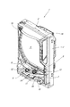
図1に示すように、パチンコ遊技機1は、木製の外枠2の前面に矩形状の前面枠3を開閉可能に取り付け、その前面枠3の裏面に取り付けられている遊技盤収納フレーム(図示せず)内に遊技盤4が装着された構成からなる。遊技盤4は、図2に示す遊技領域40を前面に臨ませた状態で装着され、図1に示すようにこの遊技領域40の前側に透明ガラスを支持したガラス扉枠5が設けられている。なお、上記遊技領域40は、遊技盤4の面上に配設された球誘導レール6(図2参照)で囲まれた領域からなるものである。
As shown in FIG. 1, the
一方、パチンコ遊技機1は、図1に示すように、ガラス扉枠5の下側に前面操作パネル7が配設され、その前面操作パネル7には上受け皿ユニット8が設けられ、この上受け皿ユニット8には、排出された遊技球を貯留する上受け皿9が一体形成されている。また、この前面操作パネル7には、球貸しボタン11及びプリペイドカード排出ボタン12(カード返却ボタン12)が設けられている。そして、上受け皿9の上皿表面部分には、内蔵ランプ(図示せず)点灯時に押下することにより演出効果を変化させることができる押しボタン式の演出ボタン装置13が設けられている。また、この上受け皿9には、当該上受け皿9に貯留された遊技球を下方に抜くための球抜きボタン14が設けられている。
On the other hand, in the
また一方、図1に示すように、前面操作パネル7の右端部側には、発射ユニットを作動させるための発射ハンドル15が設けられ、その発射ハンドル15の左側近傍及び前面枠3の上部両側面側には、BGM(Background music)あるいは効果音を発するスピーカ16が設けられている。そして、上記前面枠3の周枠には、LEDランプ等の装飾ランプLA(図8参照)が配設されている。
On the other hand, as shown in FIG. 1, on the right end side of the
他方、上記遊技盤4の遊技領域40には、図2に示すように、略中央部にLCD(Liquid Crystal Display)等からなる液晶表示装置41が配設されている。この液晶表示装置41は、表示エリアを左、中、右の3つのエリアに分割し、独立して数字やキャラクタ、文字(キャラクタの会話や歌詞テロップ等)あるいは図柄(装飾図柄)の変動表示が可能なものである。
On the other hand, in the
一方、液晶表示装置41の真下には、特別図柄1始動口42が配設され、その内部には入賞球を検出する特別図柄1始動口スイッチ42a(図3参照)が設けられている。液晶表示装置41の右下部側には、特別図柄2始動口43が配設され、その内部には入賞球を検出する特別図柄2始動口スイッチ43a(図3参照)が設けられている。そしてさらに、この特別図柄2始動口43は、図2に示すように、開閉部材43bを備えており、この開閉部材43bが開放した場合に遊技球が入賞し易い状態となる。この開閉部材43bは、後述する普通図柄の抽選に当選した場合に、所定回数、所定時間開放するもので、普通電動役物ソレノイド43c(図3参照)によって開閉動作が制御されている。なお、以下では、このような開閉部材43b及び普通電動役物ソレノイド43cを合せた装置を普通電動役物と称することがある。
On the other hand, just below the liquid
一方、液晶表示装置41の右上部側には、図2に示すように上部入賞装置44が配設されている。この上部入賞装置44は、後述する特別図柄の抽選に当選したとき、特に、大当たり遊技中に、遊技者が獲得可能な出玉が増加したかのような演出を行う大当り(以下、「ランクアップボーナス当り」という)に当選したとき、開閉部片44aにて閉止されている図示しない上部大入賞口が開放するように開閉部片44aが上部特別電動役物ソレノイド44b(図3参照)によって駆動制御され、遊技球が上部大入賞口(図示せず)に入球可能となる。なお、この上部大入賞口(図示せず)に入球した遊技球は入賞球として上部大入賞口(図示せず)内部に設けられている上部大入賞口スイッチ44c(図3参照)によって検出される。また、ランクアップボーナス当りに当選していない場合は、上部特別電動役物ソレノイド44b(図3参照)によって開閉部片44aが駆動制御され、上部大入賞口(図示せず)が閉止される。これにより、上部大入賞口(図示せず)内に遊技球が入球することができなくなる。なお、以下では、このような開閉部片44a及び上部特別電動役物ソレノイド44bを合せた装置を上部特別電動役物と称することがある。
On the other hand, on the upper right side of the liquid
また一方、特別図柄1始動口42の右側には、図2に示すように、下部入賞装置45が配設されている。この下部入賞装置45は、後述する特別図柄の抽選に当選したとき、特に、ランクアップボーナス当り以外、すなわち、大当たりの最大ラウンド数(遊技者が獲得可能な出玉数)が予め分かっている通常の大当りに当選したとき、開閉扉45aにて閉止されている図示しない下部大入賞口が開放するように開閉扉45aが下部特別電動役物ソレノイド45b(図3参照)によって駆動制御され、遊技球が下部大入賞口(図示せず)に入球可能となる。なお、この下部大入賞口(図示せず)に入球した遊技球は入賞球として下部大入賞口(図示せず)内部に設けられている下部大入賞口スイッチ45c(図3参照)によって検出される。また、通常の大当りに当選していない場合は、下部特別電動役物ソレノイド45b(図3参照)によって開閉扉45aが駆動制御され、下部大入賞口(図示せず)が閉止される。これにより、下部大入賞口(図示せず)内に遊技球が入球することができなくなる。なお、以下では、このような開閉扉45a及び下部特別電動役物ソレノイド45bを合せた装置を下部特別電動役物と称することがある。
On the other hand, on the right side of the
他方、液晶表示装置41の右上部には、図2に示すように、ゲートからなる普通図柄始動口46が配設され、その内部には、遊技球の通過を検出する普通図柄始動口スイッチ46a(図3参照)が設けられている。また、上記下部入賞装置45の右側及び上記特別図柄1始動口42の左側には、一般入賞口47が夫々配設され(図示では、右側に1つ、左側に3つ)、その内部には、夫々、遊技球の通過を検出する一般入賞口スイッチ47a(図3参照)が設けられている。
On the other hand, in the upper right portion of the liquid
また、上記遊技盤4の遊技領域40の右下周縁部には、7セグメントが3個並べて構成されており、そのうち2個の7セグメントが特別図柄表示装置48であり、他の7セグメントは特別図柄1や特別図柄2等の保留球数等を表示するものである。この特別図柄表示装置48は、図2に示すように、特別図柄1表示装置48aと特別図柄2表示装置48bとで構成されており、その特別図柄1表示装置48aの左側には、2個のLEDからなる普通図柄表示装置49が設けられている。なお、上記遊技盤4の遊技領域40には、図示はしないが複数の遊技釘が配設され、遊技球の落下方向変換部材としての風車50が配設されている。また、上記遊技盤4の遊技領域40には図示はしないが、LEDランプ等の装飾ランプLA(図8参照)が複数配設されている。
In the lower right peripheral part of the
<制御装置の説明>
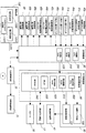
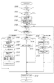
次に、上記のような外観構成からなるパチンコ遊技機1内に設けられる遊技の進行状況に応じて電子制御を行う制御装置を、図3を用いて説明する。この制御装置は、図3に示すように、遊技動作全般の制御を司る主制御基板60と、その主制御基板60からの制御コマンドに基づいて遊技球を払出す払出制御基板70と、画像と光と音についての制御を行うサブ制御基板80とで主に構成されている。なお、サブ制御基板80は、図3に示すように、演出制御基板90と、装飾ランプ基板100と、液晶制御基板120とで構成されている。
<Description of control device>
Next, a control device provided in the
主制御基板60は、主制御CPU600と、一連の遊技制御手順を記述した遊技プログラム等を格納した主制御ROM610と、作業領域やバッファメモリ等として機能する主制御RAM620とで構成されたワンチップマイクロコンピュータを搭載している。
The
そして、このように構成される主制御基板60には、払出モータMを制御して遊技球を払出す払出制御基板70が接続されている。そしてさらには、特別図柄1始動口42への入賞を検出する特別図柄1始動口スイッチ42aと、特別図柄2始動口43への入賞を検出する特別図柄2始動口スイッチ43aと、普通図柄始動口46の通過を検出する普通図柄始動口スイッチ46aと、一般入賞口47への入賞を検出する一般入賞口スイッチ47aと、開閉部片44aにて開放又は閉止される上部大入賞口(図示せず)の入賞を検出する上部大入賞口スイッチ44cと、開閉扉45aによって開放又は閉止される下部大入賞口(図示せず)の入賞を検出する下部大入賞口スイッチ45cとが接続されている。またさらには、開閉部材43bの動作を制御する普通電動役物ソレノイド43cと、開閉部片44aの動作を制御する上部特別電動役物ソレノイド44bと、開閉扉45aの動作を制御する下部特別電動役物ソレノイド45bと、特別図柄1表示装置48aと、特別図柄2表示装置48bと、普通図柄表示装置49とが接続されている。
And, to the
このように構成される主制御基板60は、特別図柄1始動口スイッチ42a又は特別図柄2始動口スイッチ43aあるいは普通図柄始動口スイッチ46aからの信号を主制御CPU600にて受信すると、遊技者に有利な特別遊技(いわゆる「大当たり」)を発生させるか、あるいは、遊技者に不利な遊技(いわゆる「ハズレ」)を発生させるかの抽選を行い、その抽選結果である当否情報に応じて特別図柄の変動パターンや停止図柄あるいは普通図柄の表示内容を決定し、その決定した情報を特別図柄1表示装置48a又は特別図柄2表示装置48bあるいは普通図柄表示装置49に送信する。これにより、特別図柄1表示装置48a又は特別図柄2表示装置48bあるいは普通図柄表示装置49に抽選結果が表示されることとなる。そしてさらに、主制御基板60、すなわち、主制御CPU600は、その決定した情報を含む演出制御コマンドを生成し、演出制御基板90に送信する。なお、主制御基板60、すなわち、主制御CPU600が、一般入賞口スイッチ47a、上部大入賞口スイッチ44c、下部大入賞口スイッチ45cからの信号を受信した場合は、遊技者に幾らの遊技球を払い出すかを決定し、その決定した情報を含む払出制御コマンドを払出制御基板70に送信することで、払出制御基板70が遊技者に遊技球を払出すこととなる。
The
また、抽選を行った結果、普通図柄の抽選に当選した場合、開閉部材43bが所定回数、所定時間開放するように普通電動役物ソレノイド43cによって駆動制御される。一方、特別図柄の抽選に当選した場合、特に、ランクアップボーナス当りに当選した場合、上部大入賞口(図示せず)が開放するように、上部特別電動役物ソレノイド44bによって開閉部片44aが制御される。そして、通常の大当りに当選した場合、下部大入賞口(図示せず)が開放するように、下部特別電動役物ソレノイド45bによって開閉扉45aが制御される。なお、この処理の詳細は後述することとする。
Further, as a result of performing the lottery, when the lottery of the normal symbol is won, the driving of the opening / closing member 43b is controlled by the normal
払出制御基板70は、上記主制御基板60(主制御CPU600)からの払出制御コマンドを受信し、その受信した払出制御コマンドに基づいて払出モータ信号を生成する。そして、その生成した払出モータ信号にて、払出モータMを制御し、遊技者に遊技球を払出す。そしてさらに、払出制御基板70は、遊技球の払出動作を示す賞球計数信号や払出動作の異常に係るステイタス信号を送信し、遊技者の操作に応答して遊技球を発射させる発射制御基板71の動作を開始又は停止させる発射制御信号を送信する処理を行う。
The
演出制御基板90は、上記主制御基板60(主制御CPU600)からの演出制御コマンドを受けて各種演出を実行制御する演出制御CPU900と、演出制御手順を記述した制御プログラム等が格納されているフラッシュメモリからなる演出制御ROM910と、作業領域やバッファメモリ等として機能する演出制御RAM920とで構成されている。そしてさらに、演出制御基板90は、所望のBGMや効果音を生成する音LSI930と、BGMや効果音等の音データ等が予め格納されている音ROM940とが搭載されている。
The
このように構成される演出制御基板90には、ランプ演出効果を現出するLEDランプ等の装飾ランプLA(図8参照)が搭載されている装飾ランプ基板100が接続され、さらに、内蔵されているランプ(図示せず)点灯時に遊技者が押下することにより演出効果を変化させることができる押しボタン式の演出ボタン装置13が接続され、BGMや効果音等を発するスピーカ16が接続されている。またさらに、演出制御基板90には、液晶表示装置41を制御する液晶制御基板120が接続されている。
A
かくして、このように構成される演出制御基板90は、主制御基板60(主制御CPU600)より送信される大当たり抽選結果(大当たりかハズレの別)に基づく特別図柄変動パターン、現在の遊技状態、始動保留球数、抽選結果に基づき停止させる装飾図柄等に必要となる基本情報を含んだ演出制御コマンドを演出制御CPU900にて受信する。そして、演出制御CPU900は、受信した演出制御コマンドに対応した演出パターンを、演出制御ROM910内に予め格納しておいた多数の演出パターンの中から抽選により決定し、その決定した演出パターンを実行指示する制御信号を演出制御RAM920内に一時的に格納する。
Thus, the
そして、演出制御CPU900は、演出制御RAM920に格納しておいた演出パターンを実行指示する制御信号のうち、音に関する制御信号を音LSI930に送信する。これを受けて音LSI930は、当該制御信号に対応する音データを音ROM940より読み出し、スピーカ16に出力する。これにより、スピーカ16より上記決定された演出パターンに対応したBGMや効果音が発せられることとなる。
Then, the
また、演出制御CPU900は、演出制御RAM920に格納しておいた演出パターンを実行指示する制御信号のうち、光に関する制御信号を装飾ランプ基板100に送信する。これにより、装飾ランプ基板100が、ランプ演出効果を現出するLEDランプ等の装飾ランプLA(図8参照)を点灯又は消灯する制御を行うため、上記決定された演出パターンに対応したランプ演出が実行されることとなる。
Further, the
さらに、演出制御CPU900は、演出制御RAM920に格納しておいた演出パターンを実行指示する制御信号のうち、画像に関する液晶制御コマンドを液晶制御基板120に送信する。これにより、液晶制御基板120が、当該液晶制御コマンドに基づく画像を表示させるように液晶表示装置41を制御することにより、上記決定された演出パターンに対応した画像が液晶表示装置41に表示されることとなる。なお、液晶制御基板120には演出内容に沿った画像を表示するための種々の画像データが記憶されており、さらに、演出出力全般の制御を担うVDP(Video Display Processor)が搭載されている。
Further, the
ところで、上記説明した各基板への電源供給は、図3に示す電源基板130より供給されている。この電源基板130は、電圧生成部1300と、電圧監視部1310と、システムリセット生成部1320とを含んで構成されている。この電圧生成部1300は、遊技店に設置された図示しない変圧トランスから供給される外部電源である交流電圧AC24Vを受けて複数種類の直流電圧を生成するもので、その生成された直流電圧は、図示はしないが各基板に供給されている。
The power supply to each substrate described above is supplied from the
また、電圧監視部1310は、上記交流電圧AC24Vの電圧を監視するもので、この電圧が遮断されたり、停電が発生したりして電圧異常を検出した場合に電圧異常信号ALARMを主制御基板60に出力するものである。なお、電圧異常信号ALARMは、電圧異常時には「L」レベルの信号を出力し、正常時には「H」レベルの信号を出力する。
Further, the
また、一方、システムリセット生成部1320は、電源投入時のシステムリセット信号を生成するもので、その生成されたシステムリセット信号は、図示はしないが各基板に出力されている。 On the other hand, the system reset generation unit 1320 generates a system reset signal when the power is turned on, and the generated system reset signal is output to each substrate although not shown.
<大当たりの処理の説明>
ここで、上記説明した制御装置のうち、本発明の特徴部分は、主制御基板60及び演出制御基板90にて処理される大当りに関する部分であるため、この点につき、図4〜図10を参照して具体的に説明する。
<Description of jackpot processing>
Here, among the control devices described above, the characterizing portion of the present invention is a portion related to the jackpot processed by the
<大当たりの種類の説明>
まず、大当たりの種類について説明すると、大当たりの種類は、ランクアップボーナス当りと呼ばれる大当りと、ランクアップボーナス当り以外、すなわち、大当たりの最大ラウンド数(遊技者が獲得可能な出玉数)が予め分かっている通常の大当りの2つに大別される。
<Description of the type of jackpot>
First, to describe the type of jackpot, the type of jackpot is known as the jackpot per rank-up bonus and the rank-up bonus other than jackpot, that is, the maximum number of rounds of jackpot (the number of payouts that the player can acquire) is known beforehand. It is divided roughly into two of the usual big hit.
<ランクアップボーナス当りについての説明>
このランクアップボーナス当りについて図4を用いて説明する。
<Description about per rank up bonus>
This rank-up bonus will be described using FIG.
特別図柄1始動口42(図2参照)へ遊技球が入賞(特別図柄1始動口スイッチ42aにて検出)又は特別図柄2始動口43(図2参照)へ遊技球が入賞(特別図柄2始動口スイッチ43aにて検出)すると、その入賞した遊技球(入賞球)に対して、大当たり、あるいは、ハズレの抽選が主制御基板60(主制御CPU600)にて行われる。そして、その抽選結果が演出制御コマンドとして主制御基板60(主制御CPU600)より演出制御基板90に送信される。
The game ball wins to the
そして、演出制御基板90は、上記演出制御コマンドを演出制御CPU900にて受信し、当該演出制御CPU900は、受信した演出制御コマンドに対応した演出パターンを演出制御ROM910内に予め格納しておいた多数の演出パターンの中から抽選により決定し、その決定した演出パターンを液晶制御コマンドとして液晶制御基板120に送信する。これにより、液晶制御基板120は、その液晶制御コマンドに基づく画像を表示させるように液晶表示装置41を制御し、上記決定された演出パターンに対応した画像を液晶表示装置41に表示させる。この液晶表示装置41に表示される画面例が図4に示すものである。
Then, the
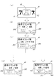
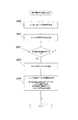
ランクアップボーナス当りに当選すると、まず、図4(a)に示すように、同一状態で停止する組み合わせ当り図柄(図示では、「7」)とは異なり、「左」の図柄(画像表示P1参照)と「右」の図柄(画像表示P2参照)とは異なる特殊図柄(図示では、「ランクアップボーナス」と表示)が「中」の図柄(画像表示P3参照)として表示される。 When winning per rank-up bonus, first, as shown in FIG. 4 (a), unlike the symbol per combination ("7" in the figure) which stops in the same state, the symbol "left" (see image display P1) And the "right" symbol (see image display P2) are displayed as the "middle" symbol (see image display P3).
次いで、図4(b)に示すように、分母に遊技者が獲得可能な出玉数(図示では、400個と表示、画像表示P4参照)、分子に遊技者が実際に獲得している出玉数(図示では、10個と表示、画像表示P4参照)が表示される。遊技者が実際に獲得している出玉数とは、上部特別電動役物ソレノイド44b(図3参照)によって開閉部片44a(図2参照)が制御され、上部大入賞口(図示せず)が開放した際、その上部大入賞口(図示せず)へ遊技球が入賞(上部大入賞口スイッチ44cにて検出)した数に応じて、遊技者に払い出される遊技球(賞球)数である。なお、画像表示P4の下部には、例えば、「ガンバレ!ガンバレ!」というセリフを言うキャラクタCH1が表示される(画像表示P5参照)。
Next, as shown in FIG. 4B, the denominator can obtain the number of payouts that can be obtained by the player (shown as 400 in the figure, refer to the image display P4), and the numerator is the one actually obtained by the player. The number of balls (in the drawing, 10 is displayed, refer to the image display P4) is displayed. The upper special
次いで、図4(c)に示すように、遊技者が、図4(b)の画像表示P4の分母に示す獲得可能な出玉数(図示では、400個と表示)を実際に獲得すると、遊技者が獲得可能な出玉数が増加、すなわち、ランプアップするか否かの演出が表示される(画像表示P6参照)。この際、画像表示P6の下部には、例えば、「ランクアップチャレンジ!」というセリフを言うキャラクタCH2が表示される(画像表示P7参照)。 Then, as shown in FIG. 4C, when the player actually acquires the obtainable number of obtainable balls (shown as 400 in the figure) shown in the denominator of the image display P4 of FIG. 4B, The number of withdrawals that can be acquired by the player is increased, that is, an effect of whether or not the lamp is up is displayed (see image display P6). At this time, under the image display P6, for example, a character CH2 that says the words "rank up challenge!" Is displayed (see image display P7).
次いで、ランクアップに失敗すると、図4(d)の画像表示P8に示すように、分母に、図4(b)の画像表示P4の分母に示す獲得可能な出玉数と同一の出玉数(図示では、400個と表示)が表示され、分子に遊技者が実際に獲得した出玉数(図示では、400個と表示)が表示され、画像表示P8の下部には、例えば、「ランクアップ失敗・・・・」というセリフを言うキャラクタCH3が表示される(画像表示P9参照)。そして、このような表示がされた後、大当たりが終了することとなる。 Next, when rank-up fails, as shown in the image display P8 of FIG. 4D, the denominator has the same number of available balls as the obtainable number of balls shown in the denominator of the image display P4 of FIG. (Displayed as 400 in the illustration), the number of balls actually obtained by the player (displayed as 400 in the illustration) is displayed on the numerator, and, for example, “Rank A character CH3 that says a line up failure ... is displayed (see image display P9). Then, after such a display is made, the jackpot ends.
一方、ランクアップに成功すると、図4(e)の画像表示P10に示すように、分母に、図4(b)の画像表示P4の分母に示す獲得可能な出玉数より増加した遊技者が獲得可能な出玉数(図示では、1200個と表示)が表示され、分子に遊技者が実際に獲得している出玉数(図示では、400個と表示)が表示され、画像表示P10の下部には、例えば、「ランクアップ成功!」というセリフを言うキャラクタCH4が表示される(画像表示P11参照)。そして、このような表示がされた後、大当たりが継続され、遊技者は、最大で1200個の出玉数を獲得することができる。 On the other hand, if the ranking is successful, as shown in the image display P10 of FIG. 4 (e), the denominator is larger than the number of obtainable payouts shown in the denominator of the image display P4 of FIG. 4 (b). The number of obtainable balls (indicated as 1200 in the figure) is displayed, the number of balls actually obtained by the player (in the figure, indicated as 400) is displayed on the numerator, and the image display P10 is displayed. In the lower part, for example, a character CH4 that says the words "rank up success!" Is displayed (see image display P11). Then, after such a display is made, the jackpot is continued, and the player can obtain a maximum of 1,200 balls.
かくして、ランクアップボーナス当りとは、遊技者が獲得できる最大出玉数を大当り開始前には分からないようにし、大当たり中に最大出玉数がランクアップするか(増加するか)否かの演出を行うことで、遊技者の興趣を向上させることができるというものである。 Thus, with the rank-up bonus, the player can not know the maximum number of balls that can be won before the big hit starts, and it is directed whether the maximum number of balls will be ranked up (increased) or not during the big hit. By doing this, the player's interest can be improved.
ところで、図4においては、遊技者が獲得できる最大出玉数が液晶表示装置41に表示されている画面例を示したが、図5に示すように、ラウンド数を表示するようにしても良い。
By the way, although FIG. 4 shows a screen example in which the maximum number of balls that can be obtained by the player is displayed on the liquid
すなわち、ランクアップボーナス当りに当選し、図5(a)に示すような画面例が表示された後、図5(b)に示すように、分母に最大ラウンド数(図示では、4Rと表示、画像表示P20参照)、分子に現在のラウンド数(図示では、1Rと表示、画像表示P20参照)が表示される。ラウンド数とは、上部特別電動役物ソレノイド44bによって開閉部片44aの開放制御を行うラウンド数をいうものである。なお、画像表示P20の下部には、例えば、「ガンバレ!ガンバレ!」というセリフを言うキャラクタCH1が表示される(画像表示P5参照)。
That is, after the screen example as shown in FIG. 5 (a) is won for each rank-up bonus, as shown in FIG. 5 (b), the maximum number of rounds is displayed in the denominator (in FIG. The image display P20) and the current number of rounds (shown as 1R in the drawing, see image display P20) are displayed on the molecule. The number of rounds refers to the number of rounds in which the opening / closing part 44a is controlled to open by the upper special
次いで、図5(c)に示すように、表示されている最大ラウンド数に達すると、最大ラウンド数が増加、すなわち、ランプアップするかの演出が表示される(画像表示P21参照)。この際、画像表示P21の下部には、例えば、「ランクアップチャレンジ!」というセリフを言うキャラクタCH2が表示される(画像表示P7参照)。 Next, as shown in FIG. 5C, when the displayed maximum number of rounds is reached, an effect of increasing the maximum number of rounds, that is, ramping up is displayed (see image display P21). At this time, under the image display P21, for example, a character CH2 that says the words "rank up challenge!" Is displayed (see image display P7).
次いで、ランクアップに失敗すると、図5(d)の画像表示P22に示すように、分母に図5(b)の画像表示P20の分母に示す最大ラウンド数と同一のラウンド数(図示では、4Rと表示)が表示され、分子に現在のラウンド数(図示では、4Rと表示)が表示され、画像表示P22の下部には、例えば、「ランクアップ失敗・・・・」というセリフを言うキャラクタCH3が表示される(画像表示P9参照)。そして、このような表示がされた後、大当たりが終了することとなる。 Next, when rank-up fails, as shown in the image display P22 of FIG. 5D, the number of rounds is the same as the maximum number of rounds shown in the denominator of the image display P20 of FIG. Is displayed, the current number of rounds (4R in the figure) is displayed on the numerator, and a character CH3 that says a line "rank up failure · · · ·" at the lower part of the image display P22, for example. Is displayed (see image display P9). Then, after such a display is made, the jackpot ends.
一方、ランクアップに成功すると、図5(e)の画像表示P23に示すように、分母に、図5(b)の画像表示P20の分母に示す最大ラウンド数より増加した最大ラウンド数(図示では、12Rと表示)が表示され、分子に現在のラウンド数(図示では、4Rと表示)が表示され、画像表示P23の下部には、例えば、「ランクアップ成功!」というセリフを言うキャラクタCH4が表示される(画像表示P11参照)。そして、このような表示がされた後、大当たりが継続され、遊技者は、最大で12R(ラウンド)のラウンド数を消化することができる。 On the other hand, if the ranking is successful, as shown in the image display P23 of FIG. 5 (e), the maximum number of rounds increased in the denominator from the maximum number of rounds shown in the denominator of the image display P20 of FIG. , 12R), the current number of rounds (4R in the figure) is displayed on the numerator, and a character CH4 that says a line saying “rank up success!” Is displayed below the image display P23. It is displayed (see image display P11). Then, after such a display is made, the jackpot is continued, and the player can digest the maximum number of rounds of 12R (round).
しかして、このようにしても、ランクアップボーナス当りとして、遊技者の興趣を向上させることができる。 Even in this case, it is possible to improve the player's interest as a rank-up bonus.
なお、ランクアップボーナス当りとして、図4に示すように遊技者が獲得できる最大出玉数を表示している場合には、図5に示すようなラウンド数を表示しないようにするのが好ましい。ラウンド数を表示してしまうと、ラウンドに応じた出玉数が遊技者に分かってしまうためである。 It is preferable not to display the number of rounds as shown in FIG. 5 when displaying the maximum number of payouts that the player can obtain as shown in FIG. 4 as the rank-up bonus. When the number of rounds is displayed, the player knows the number of balls corresponding to the round.
また、本実施形態においては、最初に表示させる最大出玉数(ランクアップ演出が行われる前に表示される最大出玉数、図4(b)の画像表示P4参照)として、400個と例示したが、一定の個数に限定されず、400個、800個、1200個などランクアップボーナス当りの種類を複数設けるようにしても良い。すなわち、ランプアップボーナス当りとして、常に、図4(b)の画像表示P4に示すように、最大出玉数が400個と表示されるのではなく、800個と表示される場合もあれば、1200個と表示される場合もある等、様々な個数が表示されるようにしても良い。このようにすれば、遊技者の興趣をさらに向上させることができる。 Further, in the present embodiment, the maximum number of popped balls to be displayed first (the maximum number of popped balls displayed before the rank-up effect is performed, see the image display P4 of FIG. 4B) is 400 and illustrated. However, the number is not limited to a fixed number, and a plurality of types may be provided per rank-up bonus, such as 400, 800, and 1200. That is, as shown in the image display P4 of FIG. 4 (b), the maximum number of pop-out balls may not always be displayed as 400 but 800 as per ramp-up bonus. Various numbers may be displayed, such as 1200 may be displayed. This makes it possible to further improve the player's interest.
<通常の大当りについての説明>
次に、通常の大当りについて図6を用いて説明する。
<Description of the normal jackpot>
Next, a normal jackpot will be described using FIG.
特別図柄1始動口42(図2参照)へ遊技球が入賞(特別図柄1始動口スイッチ42aにて検出)又は特別図柄2始動口43(図2参照)へ遊技球が入賞(特別図柄2始動口スイッチ43aにて検出)すると、その入賞した遊技球(入賞球)に対して、大当たり、あるいは、ハズレの抽選が主制御基板60(主制御CPU600)にて行われる。そして、その抽選結果が演出制御コマンドとして主制御基板60(主制御CPU600)より演出制御基板90に送信される。
The game ball wins to the
そして、演出制御基板90は、上記演出制御コマンドを演出制御CPU900にて受信し、当該演出制御CPU900は、受信した演出制御コマンドに対応した演出パターンを演出制御ROM910内に予め格納しておいた多数の演出パターンの中から抽選により決定し、その決定した演出パターンを液晶制御コマンドとして液晶制御基板120に送信する。これにより、液晶制御基板120は、その液晶制御コマンドに基づく画像を表示させるように液晶表示装置41を制御し、上記決定された演出パターンに対応した画像を液晶表示装置41に表示させる。この液晶表示装置41に表示される画面例が図6に示すものである。
Then, the
通常の大当りに当選すると、まず、図6(a)に示すように、「左」の図柄(画像表示P30参照)と、「中」の図柄(画像表示P31参照)と、「右」の図柄(画像表示P32参照)とが同一図柄で停止し(図示では、「7」)、当り図柄が表示される。なお、この際、遊技者には、ラウンドランプ(例えば、図2に示す普通図柄表示装置49の図示左側に位置するLED)の点灯により最大ラウンド数が予め分かるようになっている(本実施形態では、最大ラウンド数は16Rとしている)。
When winning a normal big hit, first, as shown in Figure 6 (a), the symbol of "left" (refer to image display P30), the symbol of "middle" (refer to image display P31), and the symbol of "right" (See image display P32) stops at the same symbol ("7" in the figure), and a hit symbol is displayed. At this time, the maximum number of rounds can be known in advance by the player by turning on the round lamp (for example, the LED located on the left side of the normal
次いで、図6(b)に示すように、例えば、「むかしむかしあるところに・・・」というセリフを言うキャラクタCH10が表示され(画像表示P33参照)、大当たり演出が開始される。この際、画像表示P33の上部には、現在のラウンド数(図示では、1ラウンド、画像表示P34参照)が表示されると共に、停止した図柄(図示では、「7」、画像表示P35参照)が表示される。 Next, as shown in FIG. 6 (b), for example, a character CH10 that says a serif “a long time ago ...” is displayed (see image display P33), and a jackpot effect is started. At this time, the current number of rounds (1 round in the figure, refer to the image display P34) is displayed in the upper part of the image display P33, and the stopped symbol (see the "7" in the drawing and the image display P35) Is displayed.
次いで、大当たり演出が進み、最終ラウンド(16R)まで進行すると、図6(c)に示すように、例えば、「めでたしめでたし」というセリフを言うキャラクタCH11が表示され(画像表示P36参照)、大当たり演出が終了する。この際、画像表示P36の上部には、最終ラウンド数(図示では、16ラウンド、画像表示P37参照)が表示されると共に、停止した図柄(図示では、「7」、画像表示P38参照)が表示される。 Next, when the jackpot effect proceeds and proceeds to the final round (16R), as shown in FIG. 6C, for example, a character CH11 that says a line saying "Make it easy" is displayed (see image display P36), and the jackpot effect Ends. At this time, the final round number (16 rounds in the figure, refer to the image display P37) is displayed in the upper part of the image display P36 and the stopped symbol (see the "7" in the drawing and the image display P38) is displayed Be done.
かくして、通常の大当りは、遊技者が、最大獲得出玉数が予め分かっているものの、遊技者にアニメーションやドラマ等のコンテンツの世界観を楽しませることで、遊技者の興趣を向上させることができるというものである。 Thus, in a normal jackpot, the player can improve the player's interest by having the player enjoy the world view of the contents such as animations and dramas although the player knows the maximum number of withdrawals in advance. It can be done.
なお、通常の大当りでは、停止した図柄(図示では、「7」)を表示するようにしたが、ランクアップボーナス当りでは表示しないようにするのが好ましい。ランクアップボーナス当りでは、表示させない方が、停止した図柄を意識せずに遊技を楽しむことができるためである。 In the normal big hit, the stopped symbol ("7" in the figure) is displayed, but it is preferable not to display it at the rank-up bonus. This is because it is possible to enjoy the game without being aware of the stopped symbol in the case of rank-up bonus, if it is not displayed.
<大当たりの種類による入賞音の説明>
しかして、このように、大当たりの種類は、ランクアップボーナス当りと呼ばれる大当りと、大当たりの最大ラウンド数(遊技者が獲得可能な出玉数)が予め分かっている通常の大当りの2種に大別され、上記説明したように、大当りの種類によって遊技者の興趣を向上させる方法が異なる。
<Description of winning sound by type of jackpot>
Thus, as described above, the type of jackpot is divided into two types: a jackpot called a rank-up bonus and a normal jackpot in which the maximum number of rounds of jackpots (the number of payouts that the player can acquire) is known in advance. As described above, the method of improving the player's interest differs depending on the type of the big hit.
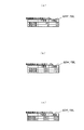
そこで、本実施形態においては、大当たり中の遊技者の興趣を向上させるため、大当たり中に遊技球が上部大入賞口(図示せず)、下部大入賞口(図示せず)に入賞した際の入賞音を大当たりの種類によって異なるようにしている。 Therefore, in the present embodiment, in order to improve the interest of the player in the big hit, when the game ball wins the upper big winning opening (not shown) and the lower big winning opening (not shown) in the big hit. The winning sound is different depending on the type of jackpot.
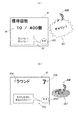
すなわち、ランクアップボーナス当りに当選した際、図7(a)に示すような画面例(画像表示P4に示すように、分母に遊技者が獲得可能な出玉数(図示では、400個と表示)、分子に遊技者が実際に獲得している出玉数(図示では、10個と表示)が表示され、画像表示P4の下部には、画像表示P5に示すように、例えば、「ガンバレ!ガンバレ!」というセリフを言うキャラクタCH1が表示)が液晶表示装置41に表示され、スピーカ16(図1参照)より大当たり中のBGMが発せられている。そしてこの際、上部特別電動役物ソレノイド44bによって開閉部片44aが制御され、上部大入賞口(図示せず)が開放し、その上部大入賞口(図示せず)へ遊技球が入賞(上部大入賞口スイッチ44cにて検出)すると、入賞したことを示す、例えば、「チャリン!」という入賞音SE1がスピーカ16(図1参照)より発せられる。この入賞音SE1の音量は、上記説明したようにランクアップボーナス当りでは、遊技者が獲得できる最大出玉数が予め分かっていないため、大当たり中の遊技者の興趣を向上させるよう、大きな音量となっている。具体的には、図7(a)に示すように、大当たり中のBGMの音量よりも大きな音量でスピーカ16より入賞音SE1が発せられている。
That is, when the player wins per rank-up bonus, the screen example as shown in FIG. 7A (as shown in the image display P4, the denominator can display the number of balls obtainable by the player (400 in the illustration) ), The number of balls actually obtained by the player is displayed on the numerator (shown as 10 in the figure), and the lower part of the image display P4 is, for example, “Ganbare!” As shown in the image display P5. The character CH1 that says the line "Gambare!" Is displayed on the liquid
一方、通常の大当りに当選した際、図7(b)に示すような画面例(画像表示P33に示すように、例えば、「むかしむかしあるところに・・・」というセリフを言うキャラクタCH10が表示され、画像表示P33の上部には、画像表示P34に示すように、現在のラウンド数(図示では、1ラウンド)が表示され、画像表示P35に示すように、停止した図柄(図示では、「7」)が表示)が液晶表示装置41に表示され、スピーカ16(図1参照)より大当たり中のBGMが発せられている。そしてこの際、下部特別電動役物ソレノイド45bによって開閉扉45aが制御され、下部大入賞口(図示せず)が開放し、その下部大入賞口(図示せず)へ遊技球が入賞(下部大入賞口スイッチ45cにて検出)すると、入賞したことを示す、例えば、「ピコ」という入賞音SE2がスピーカ16(図1参照)より発せられる。この入賞音SE2の音量は、上記説明したように、通常の大当りは、遊技者が、最大獲得出玉数が予め分かっているものの、遊技者にアニメーションやドラマ等のコンテンツの世界観を楽しませることで、遊技者の興趣を向上させるものであるため、その邪魔をしないよう、小さな音量となっている。具体的には、図7(b)に示すように、大当たり中のBGMの音量よりも小さな音量でスピーカ16より入賞音SE2が発せられている。すなわち、入賞音SE2の音量は、ランクアップボーナス当りの入賞音SE1よりも小さな音量となっている。なお、ランクアップボーナス当りの興趣をより向上させるため、入賞音SE2の音量を「0」(無音)にしても良い。
On the other hand, when the player wins a normal big hit, a screen example as shown in FIG. 7B (as shown on the image display P33, for example, a character CH10 that says a line saying "Where there is a longing ..." In the upper part of the image display P33, as shown in the image display P34, the current number of rounds (one round in the drawing) is displayed, and as shown in the image display P35, the stopped symbol (in the drawing, “7 Is displayed on the liquid
しかして、このように、大当たり中の入賞音を、大当りの種類によって異なるようにすれば、大当りの種類に関係なく、大当たり中の遊技者の興趣を向上させることができる。 Thus, by making the winning sound in the big hit different depending on the type of the big hit in this way, it is possible to improve the interest of the player in the big hit regardless of the type of the big hit.
<大当たりの種類による装飾ランプの点灯>
ところで、図7を参照して説明した上記実施形態においては、大当たり中の入賞音を、大当りの種類によって異なるようにする例を示したが、それに限らず、図8に示すように、大当たり中の装飾ランプの点灯を、大当りの種類によって異なるようにしても良い。
<Lighting of decoration lamp by kind of jackpot>
By the way, in the embodiment described above with reference to FIG. 7, an example is shown in which the winning sound in the big hit is different depending on the type of the big hit, but not limited to that, as shown in FIG. The lighting of the decoration lamp may be varied depending on the type of jackpot.
すなわち、ランクアップボーナス当りに当選した際、図8(a)に示すような画面例(画像表示P4に示すように、分母に遊技者が獲得可能な出玉数(図示では、400個と表示)、分子に遊技者が実際に獲得している出玉数(図示では、10個と表示)が表示され、画像表示P4の下部には、画像表示P5に示すように、例えば、「ガンバレ!ガンバレ!」というセリフを言うキャラクタCH1が表示)が液晶表示装置41に表示されている。そしてこの際、上部特別電動役物ソレノイド44bによって開閉部片44aが制御され、上部大入賞口(図示せず)が開放し、その上部大入賞口(図示せず)へ遊技球が入賞(上部
大入賞口スイッチ44cにて検出)すると、遊技者に入賞したことを視覚的に認識させるように遊技盤4(図2参照)の遊技領域40(図2参照)に配設されている複数の装飾ランプLAを点灯させる。このようにすれば、遊技者が獲得できる最大出玉数が増加するのではないかという期待感を煽ることができる。
That is, when the player wins per rank-up bonus, the screen example as shown in FIG. 8A (as shown in the image display P4, the denominator can display the number of balls obtainable by the player (400 in the illustration) ), The number of balls actually obtained by the player is displayed on the numerator (shown as 10 in the figure), and the lower part of the image display P4 is, for example, “Ganbare!” As shown in the image display P5. The liquid
一方、通常の大当りに当選した際、図8(b)に示すような画面例(画像表示P33に示すように、例えば、「むかしむかしあるところに・・・」というセリフを言うキャラクタCH10が表示され、画像表示P33の上部には、画像表示P34に示すように、現在のラウンド数(図示では、1ラウンド)が表示され、画像表示P35に示すように、停止した図柄(図示では、「7」)が表示)が液晶表示装置41に表示されている。そしてこの際、下部特別電動役物ソレノイド45bによって開閉扉45aが制御され、下部大入賞口(図示せず)が開放し、その下部大入賞口(図示せず)へ遊技球が入賞(下部大入賞口スイッチ45cにて検出)すると、上記説明したように、通常の大当りは、遊技者が、最大獲得出玉数が予め分かっているものの、遊技者にアニメーションやドラマ等のコンテンツの世界観を楽しませることで、遊技者の興趣を向上させるものであるため、その邪魔をしないよう、遊技盤4(図2参照)の遊技領域40(図2参照)に配設されている複数の装飾ランプLAを点灯させないか、もしくは、ランクアップボーナス当りよりも低い輝度で装飾ランプLAを点灯させるか、あるいは、開閉扉45aに配置されている装飾ランプLAのみ点灯させるようにする。
On the other hand, when a normal jackpot is won, a screen example as shown in FIG. 8B (as shown in the image display P33, for example, a character CH10 saying a line saying "in a place where there is an end") is displayed In the upper part of the image display P33, as shown in the image display P34, the current number of rounds (one round in the drawing) is displayed, and as shown in the image display P35, the stopped symbol (in the drawing, “7 Is displayed on the liquid crystal display device 41). At this time, the lower special
しかして、このように、大当たり中の装飾ランプの点灯を、大当りの種類によって異なるようにしても、大当りの種類に関係なく、大当たり中の遊技者の興趣を向上させることができる。 Thus, even if the lighting of the decoration lamp in the jackpot varies depending on the type of jackpot, the interest of the player in jackpot can be improved regardless of the type of jackpot.
なお、本実施形態においては、図7に示す入賞音SE1,SE2と、図8に示す装飾ランプLAの点灯/消灯を別々に実施する例を示したが、それに限らず、一緒にしても良い。 In the present embodiment, the winning sounds SE1 and SE2 shown in FIG. 7 and the lighting / extinguishing of the decorative lamp LA shown in FIG. 8 are separately implemented. However, the present invention is not limited thereto. .
<大当たりの種類による大入賞口の開放態様の説明>
ところで、ランクアップボーナス当りによる上部大入賞口(図示せず)の開放態様と、通常の大当りによる下部大入賞口(図示せず)の開放態様とは同一開放態様ではなく異なる開放態様となっている。
<Description of opening mode of the big winning opening by the type of jackpot>
By the way, the opening mode of the upper big winning opening (not shown) by the rank-up bonus and the opening mode of the lower big winning opening (not shown) by the usual big hit are not the same opening mode but different opening modes. There is.
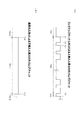
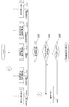
すなわち、図9(a)に示すように、ランクアップボーナス当りの場合、大当たりが開始されるインターバル期間(タイミングTS1区間参照)後、1ラウンド(1R)目が開始されると(タイミングT1参照)、上部特別電動役物ソレノイド44bによって開閉部片44aが制御され、上部大入賞口(図示せず)が開放する。そしてこの開放状態が、タイミングT1〜T2(例えば、2秒)間続き、タイミングT2時、上部特別電動役物ソレノイド44bによって開閉部片44aが制御され、上部大入賞口(図示せず)が閉止する。そしてこの閉止状態が、タイミングT2〜T3(例えば、1秒)間続き、タイミングT3時、上部特別電動役物ソレノイド44bによって開閉部片44aが制御され、上部大入賞口(図示せず)が開放することとなる。
That is, as shown in FIG. 9A, in the case of a rank-up bonus, when the first round (1R) is started after the interval period (see timing TS1 section) where the big hit is started (see timing T1) The upper special
かくして、このような上部大入賞口(図示せず)の開放閉止パターンが、1ラウンド(1R)目開始(タイミングT1参照)から終了(タイミングT4参照)までの期間(タイミングTS2区間参照)複数回(例えば、10回)続く。そして、1ラウンド(1R)目が終了すると、次の2ラウンド(2R)目へ移行するラウンド間インターバル期間(タイミングTS3区間参照)となり、その期間を経て次の2ラウンド(2R)目へ移行することとなる。なお、ラウンド間インターバル期間(タイミングTS3区間参照)は、タイミングT2〜T3(例えば、1秒)間と同一期間となっている。遊技者が獲得できる最大出玉数まで、上部大入賞口(図示せず)の開放閉止パターンが続いているかのように遊技者に見せるためである。なおまた、1ラウンド(1R)内(タイミングTS2区間参照)に、上部大入賞口(図示せず)に入賞できる数(例えば、10個)まで到達した場合は、1ラウンド(1R)の途中であっても、1ラウンド(1R)を終了し、ラウンド間インターバルを経た後で、次のラウンドである2ラウンド(2R)目に移行することとなる。 Thus, the open / close pattern of such an upper big winning opening (not shown) is repeated several times during the first round (1R) start (see timing T1) to the end (see timing T4) (see timing TS2 section) Continued (for example, 10 times). Then, when the first round (1R) ends, it becomes an inter-round interval period (refer to timing TS3 section) to shift to the next 2 rounds (2R), and after that period shifts to the next 2 rounds (2R) It will be. Note that the inter-round interval period (see timing TS3 section) is the same period as the timing T2 to T3 (for example, 1 second). This is to show the player as if the opening and closing pattern of the upper large winning opening (not shown) continues up to the maximum number of withdrawals that the player can earn. Furthermore, if the number (for example, 10) that can be won in the upper large winning opening (not shown) in one round (1R) (see timing TS2 section), in the middle of one round (1R) Even if there is, one round (1R) is finished, and after passing an inter-round interval, it will move to the next round, 2 round (2R).
一方、図9(b)に示すように、通常の大当りの場合、大当たりが開始されるインターバル期間(タイミングTS10区間参照)後、1ラウンド(1R)目が開始されると(タイミングT10参照)、下部特別電動役物ソレノイド45bによって開閉扉45aが制御され、下部大入賞口(図示せず)が開放する。そしてこの開放状態が、1ラウンド(1R)目終了(タイミングT11参照)までの期間(タイミングTS11区間参照)続き、1ラウンド(1R)目が終了すると、下部特別電動役物ソレノイド45bによって開閉扉45aが制御され、下部大入賞口(図示せず)が閉止する。次いで、次の2ラウンド(2R)目へ移行するラウンド間インターバル期間(タイミングTS12区間参照)を経て次の2ラウンド(2R)目へ移行することとなる。なお、1ラウンド(1R)内(タイミングTS11区間参照)に、下部大入賞口(図示せず)に入賞できる数(例えば、10個)まで到達した場合は、1ラウンド(1R)の途中であっても、1ラウンド(1R)を終了し、ラウンド間インターバルを経た後で、次のラウンドである2ラウンド(2R)目に移行することとなる。
On the other hand, as shown in FIG. 9B, in the case of a normal big hit, when the first round (1R) is started (see timing T10) after an interval period (see timing TS10 section) where the big hit is started, The lower special
しかして、このように、ランクアップボーナス当りによる上部大入賞口(図示せず)の開放態様と、通常の大当りによる下部大入賞口(図示せず)の開放態様を異ならせることにより、大入賞口への入賞に対する遊技者の期待感を大当たりの種類に応じて煽ることができる。 Thus, as described above, the big winning is achieved by making the opening mode of the upper big winning opening (not shown) by the rank up bonus different from the opening of the lower big winning opening (not shown) by the usual big hit. According to the type of jackpot, the player's expectation for winning in the mouth can be heard.
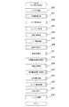
ところで、ランクアップボーナス当りに当選した場合、遊技者が獲得できる最大出玉数に係らず、ラウンド数を同じにする場合がある。遊技者が獲得できる最大出玉数に応じたラウンド数にした場合、ラウンドランプ(例えば、図2に示す普通図柄表示装置49の図示左側に位置するLED)の点灯により、ランクアップ演出の結果前に、遊技者が獲得できる最大出玉数が分かってしまうためである。すなわち、4ラウンド(4R)で最大出玉数が400個、8ラウンド(8R)で最大出玉数が800個、12ラウンド(12R)で最大出玉数が1200個、16ラウンド(16R)で最大出玉数が1600個とした場合、ラウンドランプの点灯により、ランクアップ演出の結果前に、遊技者が獲得できる最大出玉数が分かってしまう。そのため、図10に示すように、ラウンド数は16ラウンド(16R)で同じであるが、上部大入賞口(図示せず)の開放パターンを変化させるようにしている。
By the way, when the player is elected per rank-up bonus, the number of rounds may be made the same regardless of the maximum number of withdrawals that the player can acquire. If the number of rounds according to the maximum number of balls that can be obtained by the player, the round lamp (for example, the LED located on the left side of the normal
すなわち、図10(a)に示すタイミングチャートは、遊技者が獲得できる最大出玉数は400個(最初に液晶表示装置41に表示される最大出玉数(ランクアップ演出が行われる前に表示される最大出玉数)も400個)で、1ラウンド(1R)で出玉数を100個獲得することができ、ランクアップが失敗するものである。具体的には、大当たりが開始されるインターバル期間(タイミングTS20区間参照)後、1ラウンド(1R)目が開始されると(タイミングT20参照)、上部特別電動役物ソレノイド44bによって開閉部片44aが制御され、上部大入賞口(図示せず)が開放する。そしてこの開放状態が、タイミングT20〜T21(例えば、2秒)間続き、タイミングT21時、上部特別電動役物ソレノイド44bによって開閉部片44aが制御され、上部大入賞口(図示せず)が閉止する。そしてこの閉止状態が、タイミングT21〜T22(例えば、1秒)間続き、タイミングT22時、上部特別電動役物ソレノイド44bによって開閉部片44aが制御され、上部大入賞口(図示せず)が開放することとなる。
That is, in the timing chart shown in FIG. 10A, the maximum number of withdrawals that can be obtained by the player is 400 (the maximum number of withdrawals initially displayed on the liquid crystal display device 41 (displayed before rank-up effect is performed) The maximum number of balls to be dispensed) is also 400), and it is possible to obtain 100 pieces of balls in one round (1R), and the rank up fails. Specifically, when the first round (1R) is started (see timing T20) after an interval period (see timing TS20 section) in which the jackpot is started, the upper special
かくして、このような上部大入賞口(図示せず)の開放閉止パターンが、1ラウンド(1R)目開始(タイミングT20参照)から終了(タイミングT23参照)までの期間(タイミングTS21区間参照)複数回(例えば、10回)続く。そして、1ラウンド(1R)目が終了すると、次の2ラウンド(2R)目へ移行するラウンド間インターバル期間を経て次の2ラウンド(2R)目へ移行するという同一処理が4ラウンド(4R)目終了(タイミングT24参照)まで行われる(タイミングTS22区間参照)。なお、上記したように、ラウンド間インターバル期間は、タイミングT21〜T22(例えば、1秒)間と同一期間となっている。 Thus, the open / close pattern of such an upper big winning opening (not shown) is repeated several times during the first round (1R) start (see timing T20) to the end (see timing T23) (see timing TS21 section) Continued (for example, 10 times). Then, when the first round (1R) ends, the same process of moving to the next two rounds (2R) through the inter-round interval period to shift to the next two rounds (2R) is the fourth round (4R) It is performed until the end (see timing T24) (see timing TS22 section). As described above, the inter-round interval period is the same as the period between timings T21 and T22 (for example, one second).
次いで、4ラウンド(4R)目が終了(タイミングT24時参照)すると、次の5ラウンド(5R)目へ移行するラウンド間インターバル期間(タイミングTS23区間参照)となるが、このラウンド間インターバル期間(タイミングTS23区間参照)では、図4(c),図5(c)に示すようなランクアップ演出が行われているため、ラウンド間インターバルが長くなる。 Then, when the fourth round (4R) ends (refer to timing T24), it becomes an inter-round interval period (refer to timing TS23 section) to shift to the next 5 round (5R). In the section TS23, since the rank-up effect as shown in FIG. 4C and FIG. 5C is performed, the interval between rounds becomes long.
かくして、このようなラウンド間インターバル期間(タイミングTS23区間参照)が終了すると、ランクアップは失敗であるため、残りの12ラウンド(12R)を消化するために、5ラウンド(5R)目が開始されると(タイミングT25参照)、残りの12ラウンド(12R)間(タイミングTS24区間参照)、上部大入賞口(図示せず)へ遊技球が入賞できないような開放閉止が繰り返される。具体的には、5ラウンド(5R)目が開始されると(タイミングT25参照)、上部特別電動役物ソレノイド44bによって開閉部片44aが制御され、上部大入賞口(図示せず)が開放する。そしてこの開放状態が、タイミングT25〜T26(例えば、0.5秒)間続き、タイミングT26時、上部特別電動役物ソレノイド44bによって開閉部片44aが制御され、上部大入賞口(図示せず)が閉止する。そしてこの閉止状態が、タイミングT26〜T27(例えば、0.5秒)間続き、これが次のラウンド(6R)へ移行するラウンド間インターバル期間となり、この処理が16ラウンド(16R)終了まで続けられる。そして、16ラウンド(16R)目が終了すると(タイミングT28参照)、大当たりインターバル期間(タイミングTS25参照)へ移行することとなる。
Thus, at the end of such an inter-round interval period (see timing TS23 section), the fifth round (5R) is started to digest the remaining 12 rounds (12R) because the rank up is a failure. And (see timing T25), and for the remaining 12 rounds (12R) (see timing TS24 section), the opening and closing is repeated so that the game ball can not win the upper large winning opening (not shown). Specifically, when the fifth round (5R) is started (refer to timing T25), the upper special
一方、図10(b)に示すタイミングチャートは、遊技者が獲得できる最大出玉数は800個(最初に液晶表示装置41に表示される最大出玉数(ランクアップ演出が行われる前に表示される最大出玉数)は400個)で、1ラウンド(1R)で出玉数を100個獲得することができ、ランクアップが成功するものである。具体的には、大当たりが開始されるインターバル期間(タイミングTS30区間参照)後、1ラウンド(1R)目が開始されると(タイミングT30参照)、上部特別電動役物ソレノイド44bによって開閉部片44aが制御され、上部大入賞口(図示せず)が開放する。そしてこの開放状態が、タイミングT30〜T31(例えば、2秒)間続き、タイミングT31時、上部特別電動役物ソレノイド44bによって開閉部片44aが制御され、上部大入賞口(図示せず)が閉止する。そしてこの閉止状態が、タイミングT31〜T32(例えば、1秒)間続き、タイミングT32時、上部特別電動役物ソレノイド44bによって開閉部片44aが制御され、上部大入賞口(図示せず)が開放することとなる。
On the other hand, in the timing chart shown in FIG. 10B, the maximum number of withdrawals that the player can obtain is 800 (the maximum number of withdrawals initially displayed on the liquid crystal display device 41 (displayed before rank-up effect is performed) The maximum number of balls to be dispensed is 400), and it is possible to obtain 100 pieces of balls in one round (1R), and the rank up is successful. Specifically, when the first round (1R) is started (see timing T30) after an interval period (see timing TS30 section) in which the jackpot is started, the upper special
かくして、このような上部大入賞口(図示せず)の開放閉止パターンが、1ラウンド(1R)目開始(タイミングT30参照)から終了(タイミングT33参照)までの期間(タイミングTS31区間参照)複数回(例えば、10回)続く。そして、1ラウンド(1R)目が終了すると、次の2ラウンド(2R)目へ移行するラウンド間インターバル期間を経て次の2ラウンド(2R)目へ移行するという同一処理が4ラウンド(4R)目終了(タイミングT34参照)まで行われる(タイミングTS32区間参照)。なお、上記したように、ラウンド間インターバル期間は、タイミングT31〜T32(例えば、1秒)間と同一期間となっている。 Thus, the open / close pattern of such an upper big winning opening (not shown) is repeated several times during the first round (1R) start (see timing T30) to the end (see timing T33) (see timing TS31 section) Continued (for example, 10 times). Then, when the first round (1R) ends, the same process of moving to the next two rounds (2R) through the inter-round interval period to shift to the next two rounds (2R) is the fourth round (4R) It is performed until the end (see timing T34) (see timing TS32 section). As described above, the inter-round interval period is the same as the period between timings T31 to T32 (for example, one second).
次いで、4ラウンド(4R)目が終了(タイミングT34時参照)すると、次の5ラウンド(5R)目へ移行するラウンド間インターバル期間(タイミングTS33区間参照)となるが、このラウンド間インターバル期間(タイミングTS33区間参照)では、図4(c),図5(c)に示すようなランクアップ演出が行われているため、ラウンド間インターバルが長くなる。 Then, when the fourth round (4R) ends (refer to timing T34), an inter-round interval period (refer to timing TS33 section) to shift to the next fifth round (5R) will be performed. In the section TS33, since the rank-up effect as shown in FIG. 4C and FIG. 5C is performed, the interval between rounds becomes long.
かくして、このようなラウンド間インターバル期間(タイミングTS33区間参照)が終了すると、ランクアップは成功であるため、5ラウンド(5R)目が開始されると(タイミングT35参照)、上部特別電動役物ソレノイド44bによって開閉部片44aが制御され、上部大入賞口(図示せず)が開放する。そしてこの開放状態が、タイミングT35〜T36(例えば、2秒)間続き、タイミングT36時、上部特別電動役物ソレノイド44bによって開閉部片44aが制御され、上部大入賞口(図示せず)が閉止する。そしてこの閉止状態が、タイミングT36〜T37(例えば、1秒)間続き、タイミングT37時、上部特別電動役物ソレノイド44bによって開閉部片44aが制御され、上部大入賞口(図示せず)が開放することとなる。
Thus, when such an inter-round interval period (see timing TS33 section) is completed, the rank-up is successful, so when the fifth round (5R) is started (see timing T35), the upper special motorized electric product solenoid The opening / closing part 44a is controlled by 44b, and the upper big winning opening (not shown) is opened. Then, the open state continues for timing T35 to T36 (for example, 2 seconds), and at timing T36, the upper special
かくして、このような上部大入賞口(図示せず)の開放閉止パターンが、5ラウンド(1R)目開始(タイミングT35参照)から終了(タイミングT38参照)までの期間(タイミングTS34区間参照)複数回(例えば、10回)続く。そして、5ラウンド(5R)目が終了すると、次の6ラウンド(6R)目へ移行するラウンド間インターバル期間を経て次の6ラウンド(6R)目へ移行するという同一処理が8ラウンド(8R)目終了まで行われる。そして、再びランクアップ演出が行われ、失敗すれば9ラウンド(9R)目開始から16ラウンド(16R)目終了まで、図10(a)に示すタイミングTS24区間と同一の処理が行われる。他方で、成功すれば、9ラウンド(9R)目開始から図10(b)に示すタイミングTS34区間と同一の処理が行われる。 Thus, the open / close pattern of such an upper big winning opening (not shown) is repeated five times (see timing T34 section) from the fifth round (1R) start (see timing T35) to the end (see timing T38) Continued (for example, 10 times). Then, when the fifth round (5R) ends, the same process of moving to the next sixth round (6R) through the inter-round interval period to shift to the next 6 round (6R) is the eighth round (8R) It will be done until the end. Then, the rank-up effect is performed again, and if it fails, the same processing as the timing TS24 section shown in FIG. 10A is performed from the start of the ninth round (9R) to the end of the sixteenth round (16R). On the other hand, if it succeeds, the same processing as that of the timing TS34 section shown in FIG. 10B is performed from the start of the ninth round (9R).
しかして、このように、遊技者が獲得できる最大出玉数に係らず、ラウンド数を同じにし、上部大入賞口(図示せず)の開放パターンを変化させるようにしておけば、ランクアップ演出の結果前に、遊技者が獲得できる最大出玉数が分かってしまう事態を低減させることができ、もって、遊技者の興趣を向上させることができる。 Therefore, if the number of rounds is made the same and the opening pattern of the upper large winning opening (not shown) is changed regardless of the maximum number of balls that the player can earn, as described above, the rank up effect is produced. As a result, it is possible to reduce a situation in which the maximum number of withdrawals that can be obtained by the player can be known, thereby improving the player's interest.
<プログラムの説明>
次に、上記内容を踏まえ、主制御基板60及び演出制御基板90にて処理される処理内容を、図11〜図26を参照してさらに具体的に説明する。
<Description of program>
Next, based on the above contents, the processing contents to be processed by the
<主制御基板処理の説明>
まず、主制御ROM610内に格納されているプログラムの概要を図11〜図23を用いて説明する。
<Description of main control board processing>
First, an outline of a program stored in the
<メイン処理の説明>
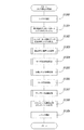
パチンコ遊技機1に電源が投入されると、電源基板130(図3参照)の電圧生成部1300にて生成された直流電圧が各制御基板に投入された旨の電源投入信号が送られ、その信号を受けて、主制御CPU600(図3参照)は、図11に示す主制御メイン処理を行う。主制御CPU600は、まず、最初に自らを割込み禁止状態に設定する(ステップS1)。
<Description of main processing>
When the
次いで、主制御CPU600は、当該主制御CPU600内のレジスタ値等の初期設定を行う(ステップS2)。
Next, the
続いて、主制御CPU600は、電源基板130(電圧監視部1310)より出力されている電圧異常信号ALARM(図3参照)を2回取得し、その2回取得した電圧異常信号ALARMのレベルが一致するか否かを確認した上で図示しない当該主制御CPU600の内部レジスタ内に格納し、その電圧異常信号ALARMのレベルを確認する(ステップS3)。そして電圧異常信号ALARMのレベルが「L」レベルであれば(ステップS4:YES)、ステップS3の処理に戻り、電圧異常信号ALARMのレベルが「H」レベルであれば(ステップS4:NO)、ステップS5の処理に進む。すなわち、主制御CPU600は、電圧異常信号ALARMが正常レベル(すなわち「H」レベル)に変化するまで同一の処理を繰り返す(ステップS3〜S4)。このように、電圧異常信号ALARMを2回取得することで、正確な信号を読み込むことができる。
Subsequently, the
次いで、主制御CPU600は、主制御RAM620(図3参照)へのデータ書込みを許可する(ステップS5)。このように、電圧異常信号ALARMの正常レベル(正常値)を検出するまで主制御RAM620へのデータ書き込みを禁止することにより、電源基板130に供給される交流電圧AC24Vが安定して供給される前に、不安定な信号が主制御RAM620にアクセスし、主制御RAM620に記憶されているデータを書き換えてしまうという事態を防止することができる。
Next, the
次いで、主制御CPU600は、演出制御基板90に液晶表示装置41に待機画面を表示させるような処理コマンド(演出制御コマンド)を送信し(ステップS6)、バックアップフラグBFLの内容を判定する(ステップS7)。なお、このバックアップフラグBFLとは、図12に示す電圧監視処理の動作が実行されたか否かを示すデータである。
Next, the
このバックアップフラグBFLがOFF状態(ステップS7:OFF)であれば、後述する図12に示す電圧監視処理の動作が実行されていないこととなり、主制御CPU600は、主制御RAM620内の全領域を全てクリアする処理を行う(ステップS11)。一方、バックアップフラグBFLがON状態(ステップS7:ON)であれば、後述する図12に示す電圧監視処理の動作が実行されていることとなるため、主制御CPU600は、チェックサム値を算出するためのチェックサム演算を行う(ステップS8)。なお、チェックサム演算とは、主制御RAM620の作業領域を対象とする8ビット加算演算である。
If this backup flag BFL is in the OFF state (step S7: OFF), it means that the operation of the voltage monitoring process shown in FIG. 12 described later is not executed, and the
そして、主制御CPU600は、上記チェックサム値が算出されたら、この演算結果を主制御RAM620内のSUM番地の記憶値と比較する処理を行う(ステップS9)。そして、記憶された演算結果は、主制御RAM620内に記憶されている他のデータと共に、電源基板130にて生成されるバックアップ電源によって維持されている。
Then, when the checksum value is calculated, the
このSUM番地の記憶値と上記ステップS8の処理にて算出されたチェックサム値が不一致(ステップS9:NO)であれば、主制御CPU600は、主制御RAM620内の全領域を全てクリアする処理を行う(ステップS11)。そして一致(ステップS9:YES)していれば、主制御CPU600は、主制御RAM620内に記憶されているデータに基づいて電源遮断時の遊技動作に復帰させる処理を行う(ステップS10)。
If the stored value at the SUM address and the checksum value calculated in the process of step S8 do not match (step S9: NO), the
次いで、主制御CPU600は、ステップS10及びステップS11の処理後、その内部に設けられている一定周期のパルス出力を作成する機能や時間計測の機能等を有するCTC(Counter Timer Circuit)の設定を行う。すなわち、主制御CPU600は、4ms毎に定期的にタイマ割込みがかかるように上記CTCの時間定数レジスタを設定する(ステップS12)。そしてその後、主制御CPU600は、ループ処理を行う。
Next, after the processing of step S10 and step S11, the
<タイマ割込み処理の説明>
続いて、図12を参照して、上述したメイン処理を中断させて、4ms毎に開始されるタイマ割込みプログラムについて説明する。このタイマ割込みが生じると、主制御CPU600内のレジスタ群の内容を主制御RAM620のスタック領域に退避させる退避処理を実行し(ステップS20)、その後電圧監視処理を実行する(ステップS21)。この電圧監視処理は、電源基板130(図3参照)から出力される電圧異常信号ALARMのレベルを判定し、電圧異常信号ALARMが「L」レベル(異常レベル)であれば、主制御RAM620内に記憶されているデータのバックアップ処理、すなわち、当該データのチェックサム値を算出し、その算出したチェックサム値をバックアップデータとして主制御RAM620内に保存する処理を行う。
<Description of timer interrupt processing>
Subsequently, with reference to FIG. 12, a timer interrupt program which is started every 4 ms by interrupting the above-described main processing will be described. When this timer interrupt occurs, save processing is performed to save the contents of the register group in the
次いで、主制御CPU600は、上記電圧監視処理(ステップS21)が終了すると、各遊技動作の時間を管理している各種タイマ(後述する普通図柄変動タイマ、普通図柄役物タイマ等)のタイマ減算処理を行う(ステップS22)。
Next, when the voltage monitoring process (step S21) is completed, the
そして続いて、主制御CPU600には、特別図柄1始動口スイッチ42a(図3参照)と、特別図柄2始動口スイッチ43a(図3参照)と、普通図柄始動口スイッチ46a(図3参照)と、一般入賞口スイッチ47a(図3参照)と、上部大入賞口スイッチ44c(図3参照)と、下部大入賞口スイッチ45c(図3参照)を含む各種スイッチ類のON/OFF信号が入力され、主制御RAM620内の作業領域にON/OFF信号レベルや、その立ち上がり状態が記憶される(ステップS23)。なお、このスイッチ入力処理は、不正入賞があった場合に、立ち上がり状態を無効(入賞無効)にする処理も行い、賞球を払出すために上記上部大入賞口スイッチ44c,下部大入賞口スイッチ45c,一般入賞口スイッチ47aに何個の遊技球が入賞したのかのカウントも行っている。
Subsequently, the
次いで、主制御CPU600は、各変動表示ゲームに係る乱数を更新する乱数管理処理を実行する(ステップS24)。この乱数管理処理は、当否抽選に使用する普通図柄当り判定用乱数を更新する処理や、特別図柄の種類を決める特別図柄用乱数を更新する処理等を実行するものである。
Next, the
次いで、主制御CPU600は、エラー管理処理を行う(ステップS25)。なお、エラー管理処理は、遊技球の補給が停止したり、あるいは、遊技球が詰まったりなど、機器内部に異常が生じていないかの判定を含むものである。
Next, the
次いで、主制御CPU600は、賞球管理処理を実行する(ステップS26)。この賞球管理処理は、払出制御基板70(図3参照)に払出し動作を行わせるための払出制御コマンドを出力している。
Next, the
次いで、主制御CPU600は、普通図柄処理を実行する(ステップS27)。この普通図柄処理は、普通図柄の当否抽選を実行し、その抽選結果に基づいて普通図柄の変動パターンや普通図柄の停止表示状態を決定したりするものである。なお、この普通図柄処理の詳細については、後述することとする。
Next, the
次いで、主制御CPU600は、普通電動役物管理処理を実行する(ステップS28)。この普通電動役物管理処理は、普通図柄処理(ステップS27)の抽選結果に基づき、普通電動役物開放遊技発生に必要な普通電動役物ソレノイド43cの制御に関する信号(普通電動役物ソレノイドフラグ)が生成される。なお、この普通電動役物管理処理の詳細については、後述することとする。
Next, the
次いで、主制御CPU600は、特別図柄処理を実行する(ステップS29)。この特別図柄処理では、特別図柄の当否抽選を実行し、その抽選の結果に基づいて特別図柄の変動パターンや特別図柄の停止表示態様(停止特別図柄)を決定する。なお、この特別図柄処理の詳細については、後述することとする。
Next, the
次いで、主制御CPU600は、特別電動役物管理処理を実行する(ステップS30)。この特別電動役物管理処理では、大当たり抽選結果に対応した当り遊技を実行制御するために必要な設定処理を行う。この際、上部特別電動役物ソレノイド44b,下部特別電動役物ソレノイド45bの制御に関する信号も生成される。なお、この特別電動役物管理処理の詳細については、後述することとする。
Next, the
次いで、主制御CPU600は、LED管理処理を実行する(ステップS31)。このLED管理処理は、処理の進行状態に応じて、特別図柄表示装置48や普通図柄表示装置49への出力データを生成したり、当該データに基づく制御信号を出力したりする処理である。
Next, the
次いで、主制御CPU600は、ソレノイド駆動処理を行う(ステップS32)。この際、主制御CPU600は、普通電動役物管理処理(ステップS28)にて生成された普通電動役物ソレノイド43cの制御に関する信号を確認すると共に、特別電動役物管理処理(ステップS30)にて生成された上部特別電動役物ソレノイド44b,下部特別電動役物ソレノイド45bの制御に関する信号を確認する。そして、普通電動役物ソレノイド43cの信号内容に応じて、普通電動役物ソレノイド43cを制御することにより、開閉部材43bが開閉することとなる。さらに、上部特別電動役物ソレノイド44bの信号内容に応じて、上部特別電動役物ソレノイド44bを制御することにより、開閉部片44aが開閉し、もって、上部大入賞口(図示せず)が開閉することとなる。そしてさらに、下部特別電動役物ソレノイド45bの信号内容に応じて、下部特別電動役物ソレノイド45bを制御することにより、開閉扉45aが開閉し、もって、下部大入賞口(図示せず)が開閉することとなる。
Next, the
次いで、主制御CPU600は、割込み許可状態に戻し(ステップS33)、主制御RAM620のスタック領域に退避させておいたレジスタの内容を復帰させタイマ割込みを終える(ステップS34)。これにより、割込み処理ルーチンからメイン処理(図11参照)に戻ることとなる。
Next, the
<普通図柄処理の説明>
次に、図13を参照して、上記普通図柄処理(図12のステップS27)について詳細に説明する。
<Description of normal symbol processing>
Next, with reference to FIG. 13, the above-mentioned normal symbol processing (step S27 of FIG. 12) will be described in detail.
図13に示すように、普通図柄処理は、先ず、ゲートからなる普通図柄始動口46(図2参照)において、遊技球の通過を検出したか否かを確認、すなわち、普通図柄始動口46の普通図柄始動口スイッチ46aの信号レベルを確認する(ステップS100)。そして遊技球の通過を検出した場合(ステップS100:YES)、主制御CPU600は、普通図柄の始動保留球数が例えば4以上か否かを判断するため、普通図柄の始動保留球数が格納されている主制御RAM620領域を確認する(ステップS101)。その際、普通図柄の始動保留球数が4未満であれば(ステップS101:≠MAX)、普通図柄の始動保留球数を1加算する(ステップS102)。その後、主制御CPU600は、普通図柄の当否抽選に用いられる普通図柄当り判定用乱数値を普通図柄の始動保留球数が格納されている主制御RAM620領域に格納した上で(ステップS103)、ステップS104の処理に進む。
As shown in FIG. 13, the normal symbol processing first confirms whether or not passage of the game ball is detected in the normal symbol starting opening 46 (see FIG. 2) consisting of a gate, that is, the normal
一方、ステップS100にて、遊技球の通過を検出しなかった場合(ステップS100:NO)、ステップS101にて、普通図柄の始動保留球数が4以上であると判断した場合(ステップS101:=MAX)には、ステップS102〜S103の処理は行わず、ステップS104の処理に進む。 On the other hand, when passage of the game ball is not detected in step S100 (step S100: NO), when it is determined in step S101 that the number of starting holding balls for normal symbols is 4 or more (step S101: = In MAX), the process of steps S102 to S103 is not performed, and the process proceeds to step S104.
主制御CPU600は、ステップS104の処理に進むと、普通図柄当たり作動フラグがONに設定されているか、すなわち、普通図柄当たり作動フラグに5AHが設定されているかを確認する(ステップS104)。普通図柄当たり作動フラグに5AHが設定されていれば(ステップS104:ON)、普通図柄が当たり中であると判断し、普通図柄の表示データの更新を行った後(ステップS113)、普通図柄処理を終える。
When the
一方、普通図柄当たり作動フラグに5AHが設定されていなければ(ステップS104:OFF)、普通図柄の挙動を示す処理状態、すなわち、普通図柄動作ステータスフラグの値を確認する(ステップS105)。そして、普通図柄動作ステータスフラグが00Hであれば、主制御CPU600は、普通図柄の変動開始前の状態であると判断し、ステップS106に進み、普通図柄の始動保留球数が0か否かを確認する(ステップS106)。
On the other hand, if 5AH is not set in the normal symbol hit operation flag (step S104: OFF), the processing state indicating the behavior of the normal symbol, that is, the value of the normal symbol operation status flag is confirmed (step S105). Then, if the normal symbol operation status flag is 00H, the
主制御CPU600は、普通図柄の始動保留球数が格納されている主制御RAM620領域を確認した上で、0であると判断した場合(ステップS106:=0)は、普通図柄の表示データの更新を行った後(ステップS113)、普通図柄処理を終える。一方、0でないと判断した場合(ステップS106:≠0)は、普通図柄の始動保留球数を1減算する(ステップS107)。
When the
その後、主制御CPU600は、図17(a)に示す普通図柄当たり判定テーブルNPP_TBLを用いて主制御RAM620領域に格納されている普通図柄の始動保留球数に対応した乱数値の当たり判定を行う。すなわち、主制御CPU600は、遊技状態を示す普通図柄確変フラグがOFFであれば、当該乱数値が、図17(a)に示す普通図柄当たり判定テーブルNPP_TBL(通常状態)の下限値(図示では、249)以上で上限値(図示では、250)以下か否かを判定し、下限値以上で上限値以下であれば、普通図柄当たり判定フラグに5AHをセットし、ONにする。それ以外の場合は、普通図柄当たり判定フラグをOFFにする。
After that, the
一方、遊技状態を示す普通図柄確変フラグがONであれば、当該乱数値が、図17(a)に示す普通図柄当たり判定テーブルNPP_TBL(確変状態)の下限値(図示では、4)以上で上限値(図示では、250)以下か否かを判定し、下限値以上で上限値以下であれば、普通図柄当たり判定フラグに5AHをセットし、ONにする。それ以外の場合は、普通図柄当たり判定フラグをOFFにセットする処理を行う(ステップS108)。 On the other hand, if the normal symbol probability change flag indicating the gaming state is ON, the random number value is the upper limit over the lower limit value (4 in the figure) of the normal symbol hit determination table NPP_TBL (probability variation state) shown in FIG. It is determined whether or not it is a value (250 in the figure) or less, and if it is not less than the lower limit value and not more than the upper limit value, 5AH is set to the normal symbol hitting determination flag and it is turned ON. In the other cases, the normal symbol hitting determination flag is set to OFF (step S108).
そして、主制御CPU600は、上記乱数抽選処理にて決定した抽選結果に基づいて、停止図柄(普通図柄停止図柄)を決定する(ステップS109)。
Then, the
次いで、主制御CPU600は、普通図柄の変動時間を短くする普通図柄時短フラグがONに設定されているかを確認し、ONに設定されていれば、普通図柄変動タイマにそれに応じた変動時間を設定し、OFFに設定されていれば、普通図柄変動タイマに通常の変動時間を設定する処理を行う(ステップS110)。
Next, the
次いで、主制御CPU600は、普通図柄の始動保留球数に対応した普通図柄の当否抽選に用いられる乱数値が格納されている主制御RAM620領域の記憶領域をシフトする(ステップS111)。すなわち、普通図柄の始動保留球数を最大で4個保留できるとすると、普通図柄の始動保留球数4に対応した普通図柄の当否抽選に用いられる乱数値を普通図柄の始動保留球数3に対応した普通図柄の当否抽選に用いられる乱数値が格納されていた主制御RAM620領域にシフトし、普通図柄の始動保留球数3に対応した普通図柄の当否抽選に用いられる乱数値を普通図柄の始動保留球数2に対応した普通図柄の当否抽選に用いられる乱数値が格納されていた主制御RAM620領域にシフトし、普通図柄の始動保留球数2に対応した普通図柄の当否抽選に用いられる乱数値を普通図柄の始動保留球数1に対応した普通図柄の当否抽選に用いられる乱数値が格納されていた主制御RAM620領域にシフトするという処理を行う。
Next, the
この処理の後、主制御CPU600は、上記ステップS105にて用いた普通図柄動作ステータスフラグに01Hを設定し、普通図柄の始動保留球数4に対応した普通図柄の当否抽選に用いられる乱数値が格納されていた主制御RAM620の領域に00Hを設定する処理を行う(ステップS112)。
After this processing, the
そして、主制御CPU600は、上記ステップS112の処理を終えた後、普通図柄の表示データの更新を行い(ステップS113)、普通図柄処理を終える。
Then, after finishing the process of step S112, the
他方、主制御CPU600は、上記ステップS105にて、普通図柄の挙動を示す処理状態、すなわち、普通図柄動作ステータスフラグの値が01Hであれば、主制御CPU600は、普通図柄が変動中であると判断し、ステップS114に進み、普通図柄変動タイマが0か否かを確認する(ステップS114)。普通図柄変動タイマが0でなければ(ステップS114:≠0)、普通図柄の表示データの更新を行い(ステップS113)、普通図柄処理を終える。そして、普通図柄変動タイマが0であれば(ステップS114:=0)、主制御CPU600は、上記ステップS105にて用いた普通図柄動作ステータスフラグに02Hを設定し、普通図柄の当否抽選結果を一定時間維持させるために、普通図柄変動タイマに例えば約600msの時間が設定される(ステップS115)。
On the other hand, at step S105, the
主制御CPU600は、上記ステップS115の処理を終えた後、普通図柄の表示データの更新を行い(ステップS113)、普通図柄処理を終える。
After finishing the processing of step S115, the
一方、主制御CPU600は、上記ステップS105にて、普通図柄の挙動を示す処理状態、すなわち、普通図柄動作ステータスフラグの値が02Hであれば、主制御CPU600は、普通図柄が確認時間中(普通図柄の変動が終了して停止中)であると判断し、ステップS116に進み、普通図柄変動タイマが0か否かを確認する(ステップS116)。普通図柄変動タイマが0でなければ(ステップS116:≠0)、普通図柄の表示データの更新を行い(ステップS113)、普通図柄処理を終える。そして、普通図柄変動タイマが0であれば(ステップS116:=0)、主制御CPU600は、上記ステップS105にて用いた普通図柄動作ステータスフラグに00Hを設定し(ステップS117)、普通図柄当たり判定フラグがONに設定(5AHが設定)されているかを確認する(ステップS118)。
On the other hand,
これにより、普通図柄当たり判定フラグがOFFに設定(5AHが設定されていない)されていれば(ステップS118:OFF)、主制御CPU600は、普通図柄の表示データの更新を行い(ステップS113)、普通図柄処理を終える。そして、普通図柄当たり判定フラグがONに設定(5AHが設定)されていれば(ステップS118:ON)、主制御CPU600は、ステップS104にて用いられる普通図柄当たり作動フラグをON(5AHを設定)に設定した(ステップS119)後、普通図柄処理を終える。
Thereby, if the normal symbol winning determination flag is set to OFF (5AH is not set) (step S118: OFF), the
<普通電動役物管理処理の説明>
次に、図14を参照して、上記普通電動役物管理処理(図12のステップS28)について詳細に説明する。
<Description of ordinary electric role management processing>
Next, with reference to FIG. 14, the above-mentioned ordinary motor-operated role management process (step S28 in FIG. 12) will be described in detail.
図14に示すように、主制御CPU600は、まず、普通図柄当たり作動フラグに5AHが設定されているかを確認する(ステップS200)。普通図柄当たり作動フラグに5AHが設定されていなければ(ステップS200:OFF)、普通図柄が当り中でないと判断し、普通電動役物管理処理を終える。
As shown in FIG. 14, the
一方、普通図柄当たり作動フラグに5AHが設定されていれば(ステップS200:ON)、主制御CPU600は、普通電動役物が作動中か否かを確認する(ステップS201)。具体的には、後述する普通電動役物作動中フラグを確認する。普通電動役物作動中フラグに「1」が設定されていると、普通電動役物が作動中であると判断し(ステップS201:YES)、後述する普通電動役物入賞カウンタを確認する(ステップS202)。この普通電動役物入賞カウンタは、特別図柄2始動口スイッチ43a(図3参照)にて検出された入賞球をカウントするもので、図12に示すスイッチ入力処理(ステップS23)にて管理されている。
On the other hand, if 5AH is set to the normal symbol winning operation flag (step S200: ON), the
普通電動役物入賞カウンタの値が最大数以上であれば、普通図柄役物タイマに0を設定し、最大数より小さければ、何もせず、ステップS203の処理に進む。 If the value of the ordinary motor winning combination winning counter is greater than or equal to the maximum number, 0 is set to the ordinary symbol combination timer, and if it is smaller than the maximum number, nothing is performed and the process proceeds to step S203.
一方、普通電動役物作動中フラグに「0」が設定されていると、主制御CPU600は、普通電動役物が作動中でないと判断し(ステップS201:NO)、ステップS202の処理をせず、ステップS203の処理に進む。
On the other hand, if the normal motor-operated product operating flag is set to "0", the
次いで、主制御CPU600は、普通図柄役物タイマの値を確認する(ステップS203)。普通図柄役物タイマの値が「0」であれば(ステップS203:=0)、主制御CPU600は、普通電動役物動作ステータスフラグに従って、各設定値をセットする。具体的には、普通電動役物動作ステータスフラグに00Hが設定されていると、普通電動役物の動作開始前の状態であると判断し、普通電動役物タイマに20msを設定することで、普通電動役物の開始インターバル時間を設定する。そして、普通電動役物動作ステータスフラグに01Hを設定し、ステップS205の処理に移行する。
Next, the
一方、普通電動役物動作ステータスフラグに01Hが設定されていると、主制御CPU600は、普通電動役物の動作開始インターバル終了時であると判断し、普通電動役物タイマに、開閉部材43bの開放延長機能の作動/未作動に応じた値が設定される。そして、普通電動役物入賞カウンタに0を設定し、普通電動役物動作ステータスフラグに02Hを設定し、ステップS205の処理に移行する。
On the other hand, when 01H is set in the normal motor combination product operation status flag, the
また、普通電動役物動作ステータスフラグに02Hが設定されていると、主制御CPU600は、普通電動役物の動作終了時であると判断し、普通電動役物ソレノイドフラグに「0」を設定し、普通電動役物作動中フラグに「0」を設定し、普通電動役物タイマに20msを設定することで、普通電動役物の終了インターバル時間を設定する。そして、普通電動役物有効タイマに1sを設定し、普通電動役物動作ステータスフラグに03Hを設定し、ステップS205の処理に移行する。
Also, if 02H is set in the normal motor combination product operation status flag, the
また一方、普通電動役物動作ステータスフラグに03Hが設定されていると、主制御CPU600は、普通電動役物の動作終了インターバル終了時であると判断し、普通電動役物入賞カウンタに「0」を設定し、普通図柄当たり作動フラグに00Hを設定し、普通電動役物動作ステータスフラグに00Hを設定し、ステップS205の処理に移行する。
On the other hand, when 03H is set in the normal motor combination product operation status flag, the
他方、主制御CPU600は、普通図柄役物タイマの値が「0」でなければ(ステップS203:≠0)、ステップS204の処理をせず、ステップS205の処理に移行する。
On the other hand, the
次いで、主制御CPU600は、普通電動役物動作ステータスフラグを確認し、02Hが設定されていなければ(ステップS205:NO)、普通電動役物管理処理を終える。
Next, the
一方、02Hが設定されていれば(ステップS205:YES)、普通電動役物ソレノイドフラグに「1」を設定し、普通電動役物作動中フラグに「1」を設定し(ステップS206)、普通電動役物管理処理を終える。なお、この普通電動役物ソレノイドフラグの値が「1」であれば、開閉部材43bが開放するように普通電動役物ソレノイド43cを制御し、普通電動役物ソレノイドフラグの値が「0」であれば、開閉部材43bが閉止するように普通電動役物ソレノイド43cを制御する。
On the other hand, if 02H is set (step S205: YES), "1" is set to the normal motor combination solenoid flag, and "1" is set to the normal power combination in progress flag (step S206). Finish the electric role management process. In addition, if the value of the common electric combination solenoid flag is "1", the normal combination
<特別図柄処理の説明>
次に、図15及び図16を参照して、上記特別図柄処理(図12のステップS29)について詳細に説明する。図15に示すように、特別図柄処理は、先ず、特別図柄1始動口42(図2参照)の特別図柄1始動口スイッチ42a(図3参照)において、遊技球の入球(入賞球)を検出した否かを確認し(ステップS300)、さらに、特別図柄2始動口43(図2参照)の特別図柄2始動口スイッチ43aにおいて、遊技球の入球(入賞球)を検出したか否かを確認する(ステップS301)。
<Description of special symbol processing>
Next, with reference to FIG.15 and FIG.16, the said special symbol process (FIG.12 S29) is demonstrated in detail. As shown in FIG. 15, in the special symbol processing, first, in the
<特別図柄処理:始動口チェック処理の説明>
この処理について、図16を用いて詳しく説明すると、主制御CPU600は、特別図柄1始動口42又は特別図柄2始動口43に遊技球が入球(入賞)したか否かを確認、すなわち、特別図柄1始動口42の特別図柄1始動口スイッチ42a又は特別図柄2始動口43の特別図柄2始動口スイッチ43aのレベルを確認する(ステップS400)。これにより、遊技球の入球(入賞)を検出しなければ(ステップS400:NO)、特別図柄処理を終える。
<Special symbol processing: Explanation of starting opening check processing>
This process will be described in detail with reference to FIG. 16. The
一方、遊技球の入球(入賞)を検出すれば(ステップS400:YES)、主制御CPU600は、特別図柄の変動契機となる始動保留球数が所定数、主制御RAM620内の始動保留記憶領域に格納されているか否かを確認する(ステップS401)。その始動保留球数が、4未満であれば(ステップS401:≠MAX)、当該始動保留球数を1加算(+1)する(ステップS402)。
On the other hand, if the entry (winning) of the game ball is detected (step S400: YES), the
次いで、主制御CPU600は、特別図柄停止の際用いられる乱数値及び変動パターン用乱数値並びに大当たり判定用乱数値を特別図柄の変動契機となる始動保留球数が格納されている主制御RAM620内の始動保留記憶領域に格納する(ステップ403)。
Next, the
次いで、主制御CPU600は、現在の遊技状態(特別図柄大当たり判定フラグがONに設定されているか否か等)を確認し、先読み禁止状態か否かを判定する(ステップS404)。そして、先読み禁止状態でなければ(ステップS404:NO)、主制御CPU600は、上記ステップS403にて主制御RAM620内の始動保留記憶領域に格納した特別図柄の当否抽選に用いられる大当たり判定用乱数値を取得し(ステップS405)、さらに、図示しない始動口入賞時乱数判定テーブルを取得する(ステップS406)。
Next, the
次いで、主制御CPU600は、上記ステップS405にて取得した大当たり判定用乱数値及びステップS406にて取得した始動口入賞時乱数判定テーブル(図示せず)を用いて、大当たり抽選を行い、さらに、上記ステップS403にて主制御RAM620内の始動保留記憶領域に格納した特別図柄用乱数値を用いて、大当たりの種類(ランクアップボーナス当り,通常の大当り等)を決定し、変動パターン用乱数値を用いて、変動パターンを決定し、それに応じた特別図柄始動口入賞コマンドを生成する(ステップS407)。
Next, the
次いで、主制御CPU600は、上記生成された特別図柄始動口入賞コマンドに応じた下位バイトの始動保留加算コマンドを生成する(ステップS408)。
Next, the
一方、主制御CPU600は、上記ステップS408の処理を終えるか、又は、上記ステップS401にて特別図柄1又は2の始動保留球数が4以上であるか(ステップS401:=MAX)、あるいは、先読み禁止状態であれば(ステップS404:YES)、増加した始動保留球数に応じた上位バイトの始動保留加算コマンドを生成する(ステップS409)。
On the other hand, the
次いで、主制御CPU600は、上記ステップS408にて生成した下位バイトの始動保留加算コマンドと、上記ステップS409にて生成した上位バイトの始動保留加算コマンドとを結合した上で、始動保留加算コマンド(演出制御コマンド)として、演出制御基板90(図3参照)に送信する処理を行う(ステップS410)。
Next, the
<特別図柄処理の説明>
かくして、図15に示すステップS300及びステップS301の処理を終えると、主制御CPU600は、特別図柄小当たり作動フラグがONに設定されているか、すなわち、特別図柄小当たり作動フラグに5AHが設定されているかを確認する(ステップS302)。特別図柄小当たり作動フラグに5AHが設定されていれば(ステップS302:ON)、特別図柄が小当たり中であると判断し、特別図柄の表示データの更新を行った後(ステップS308)、特別図柄処理を終える。
<Description of special symbol processing>
Thus, when the processing of step S300 and step S301 shown in FIG. 15 is finished, the
一方、特別図柄小当たり作動フラグに5AHが設定されていなければ(ステップS302:OFF)、特別図柄大当たり作動フラグがONに設定されているか、すなわち、特別図柄大当たり作動フラグに5AHが設定されているかを確認する(ステップS303)。特別図柄大当たり作動フラグに5AHが設定されていれば(ステップS303:ON)、特別図柄が大当たり中であると判断し、特別図柄の表示データの更新を行った後(ステップS308)、特別図柄処理を終える。 On the other hand, if 5AH is not set in the special symbol small hitting operation flag (step S302: OFF), is the special symbol large hitting operation flag set to ON, that is, 5AH is set in the special symbol large hitting operation flag (Step S303). If 5AH is set to the special symbol jackpot operation flag (step S303: ON), it is determined that the special symbol is in the middle of a big hit, and after the display data of the special symbol is updated (step S308), the special symbol processing is performed. Finish.
一方、特別図柄大当たり作動フラグに5AHが設定されていなければ(ステップS303:OFF)、特別図柄の挙動を示す処理状態、すなわち、特別図柄動作ステータスフラグの値を確認する(ステップS304)。より詳しく説明すると、主制御CPU600は、特別図柄動作ステータスフラグの値が00H又は01Hであれば、特別図柄変動待機中(特別図柄の変動が行われておらず次回の変動のための待機状態であることを示す)であると判定し、特別図柄変動開始処理を行う(ステップS305)。
On the other hand, if 5AH is not set in the special symbol big hit operation flag (step S303: OFF), the processing state indicating the behavior of the special symbol, that is, the value of the special symbol operation status flag is confirmed (step S304). Explaining in more detail, if the value of the special symbol operation status flag is 00H or 01H, the
この特別図柄変動開始処理にて、図16に示すステップS403にて主制御RAM620内の始動保留記憶領域に格納した各保留球数(保留1〜4)に対応した乱数値(大当たり判定用乱数値)が、特別図柄の大当たりか小当たりかを図17(b)に示す特別図柄大当たり判定テーブルSDH_TBL、図17(c)に示す特別図柄小当たり判定テーブルSDP_TBLを用いて判定する。すなわち、主制御CPU600は、遊技状態を示す特別図柄確変フラグがOFFであれば、大当たり判定用乱数値が、図17(b)に示す特別図柄大当たり判定テーブルSDH_TBL(通常状態)の下限値(図示では、10001)以上で上限値(図示では、10164)以下か否かを判定し、下限値以上で上限値以下であれば、特別図柄大当たり判定フラグに5AHをセットし、ONにする。それ以外の場合は、特別図柄大当たり判定フラグをOFFにする。
In this special symbol variation start process, random number value (big hit determination random number value corresponding to the number of pending balls (pending 1 to 4) stored in the start pending storage area in the
一方、遊技状態を示す特別図柄確変フラグがONであれば、大当たり判定用乱数値が、図17(b)に示す特別図柄大当たり判定テーブルSDH_TBL(確変状態)の下限値(図示では、10001)以上で上限値(図示では、11640)以下か否かを判定し、下限値以上で上限値以下であれば、特別図柄大当たり判定フラグに5AHをセットし、ONにする。それ以外の場合は、特別図柄大当たり判定フラグをOFFにセットする処理を行う。 On the other hand, if the special symbol probability change flag indicating the gaming state is ON, the jackpot determination random number value is equal to or more than the lower limit (10001 in the figure) of the special symbol jackpot determination table SDH_TBL (probability variation state) shown in FIG. It is determined whether the upper limit (in the figure, 11640) or less is determined, and if it is not less than the lower limit and not more than the upper limit, 5AH is set in the special symbol jackpot determination flag and turned ON. Otherwise, the special symbol jackpot determination flag is set to OFF.
他方、主制御CPU600は、特別図柄2変動中フラグがOFFであれば、大当たり判定用乱数値が、図17(c)に示す特別図柄小当たり判定テーブルSDP_TBL(特別図柄1)の下限値(図示では、20001)以上で上限値(図示では、20164)以下か否かを判定し、下限値以上で上限値以下であれば、特別図柄小当たり判定フラグに5AHをセットし、ONにする。それ以外の場合は、特別図柄小当たり判定フラグをOFFにセットする処理を行う。
On the other hand, if the
一方、特別図柄2変動中フラグがONであれば、大当たり判定用乱数値が、図17(c)に示す特別図柄小当たり判定テーブルSDP_TBL(特別図柄2)の下限値(図示では、20001)以上で上限値(図示では、20082)以下か否かを判定し、下限値以上で上限値以下であれば、特別図柄小当たり判定フラグに5AHをセットし、ONにする。それ以外の場合は、特別図柄小当たり判定フラグをOFFにセットする処理を行う。
On the other hand, if the
他方、特別図柄動作ステータスフラグの値が02Hの場合、主制御CPU600は、特別図柄変動中(特別図柄が現在変動中であることを示す)であると判定し、特別図柄変動中処理を行う(ステップS306)。この特別図柄変動中処理にて、特別図柄の変動停止コマンド(演出制御コマンド)が演出制御基板90(図3参照)に送信される。これにより、液晶表示装置41に表示される特別図柄が上記特別図柄変動開始処理にて生成された特別図柄の停止図柄の内容にて停止することとなる。なお、このような処理を終えた後、特別図柄動作ステータスフラグの値に03Hがセットされることとなる。
On the other hand, when the value of the special symbol operation status flag is 02H, the
一方、特別図柄動作ステータスフラグの値が03Hの場合、主制御CPU600は、特別図柄確認中(特別図柄の変動が終了して停止中であることを示す)であると判定し、特別図柄確認時間中処理を行う(ステップS307)。なお、このような処理を終えた後、特別図柄動作ステータスフラグの値に00Hがセットされることとなる。
On the other hand, when the value of the special symbol operation status flag is 03H, the
このように、上記ステップS305、ステップS306、ステップS307のいずれかの処理を終えると、主制御CPU600は、特別図柄の表示データの更新を行った後(ステップS308)、特別図柄処理を終える。
As described above, when the processing in any of the step S305, the step S306, and the step S307 is finished, the
<特別電動役物管理処理の説明>
次に、図18〜図23を参照して、上記特別電動役物管理処理(図12のステップS30)について詳細に説明する。
<Description of special electric role management processing>
Next, with reference to FIG. 18 to FIG. 23, the above-mentioned special motorized prize management process (step S30 in FIG. 12) will be described in detail.
図18に示すように、主制御CPU600は、まず、特別図柄小当たり作動フラグがONに設定されているか、すなわち、特別図柄小当たり作動フラグに5AHが設定されているかを確認する(ステップS500)。特別図柄小当たり作動フラグに5AHが設定されていれば(ステップS500:ON)、特別図柄が小当たり中であると判断し、小当たり遊技に係る下部入賞装置45の一連の動作を制御するための小当たり処理を行い(ステップS501)、特別電動役物管理処理を終える。
As shown in FIG. 18, the
一方、特別図柄小当たり作動フラグに5AHが設定されていなければ(ステップS500:OFF)、特別図柄大当たり作動フラグがONに設定されているか、すなわち、特別図柄大当たり作動フラグに5AHが設定されているかを確認する(ステップS502)。特別別図柄大当たり作動フラグに5AHが設定されていれば(ステップS502:ON)、特別図柄が大当たり中であると判断し、特別電動役物管理処理を終える。 On the other hand, if 5AH is not set in the special symbol small hit operation flag (step S500: OFF), is the special symbol large hit operation flag set to ON, that is, 5AH is set in the special symbol large hit operation flag? (Step S502). If 5AH is set to the special separate symbol jackpot operation flag (step S502: ON), it is determined that the special symbol is in the middle of a big hit, and the special electric symbol management process ends.
一方、特別図柄大当たり作動フラグに5AHが設定されていなければ(ステップS502:OFF)、特別電動役物の動作状態、すなわち、特別電動役物動作ステータスフラグの値を確認する(ステップS503)。より詳しく説明すると、特別電動役物動作ステータスフラグに00Hが設定されていれば、開始処理中(大当たり遊技開始前の待機状態であることを示す)であると判定し、大当たり開始処理(ステップS504)を行う。そして、特別電動役物動作ステータスフラグに01Hが設定されていれば、作動開始処理中(ラウンド遊技開始前の待機状態であることを示す)であると判定し、特別電動役物作動開始処理(ステップS505)を行う。また、特別電動役物動作ステータスフラグに02Hが設定されていれば、作動中(ラウンド遊技が実行中であることを示す)であると判定し、特別電動役物作動中処理(ステップS506)を行う。またさらに、特別電動役物動作ステータスフラグに03Hが設定されていれば、継続判定中(次回のラウンド遊技を継続させるか否かの判定中であることを示す)であると判定し、特別電動役物作動継続判定処理(ステップS507)を行う。そして、特別電動役物動作ステータスフラグに04Hが設定されていれば、終了処理中(大当たり遊技終了時の終了処理中であることを示す)であると判定し、大当たり終了処理(ステップS508)を行う。 On the other hand, if 5AH is not set to the special symbol jackpot operation flag (step S502: OFF), the operation state of the special electric symbol, that is, the value of the special electric symbol operation status flag is confirmed (step S503). More specifically, if 00H is set in the special electric role thing operation status flag, it is determined that the start processing is in progress (indicating that it is in the standby state before the start of the jackpot game), and the jackpot start processing (step S504) )I do. Then, if 01H is set in the special electric combination product operation status flag, it is determined that the operation start process is in progress (indicating that it is in the standby state before the start of the round game), and the special electric combination product operation start process ( Step S505) is performed. Further, if 02H is set in the special electric combination product operation status flag, it is determined that it is in operation (indicating that a round game is being executed), and the special electric combination product in operation processing (step S506) Do. Furthermore, if 03H is set in the special electric combination product operation status flag, it is determined that the continuation determination is underway (indicating that it is being determined whether or not to continue the next round game), and special electric A bonus item operation continuation determination process (step S507) is performed. Then, if 04H is set in the special electric combination product operation status flag, it is determined that the end processing is in progress (indicating that the end processing at the end of the big hit game is in progress), the big hit end processing (step S508) Do.
このようにして、ステップS504〜ステップS508の何れかの処理を終えると、主制御CPU600は、特別電動役物管理処理を終える。
As described above, when any processing of step S504 to step S508 is finished, the
ここで、ステップS504〜ステップS508の処理について、図19〜図23を参照して具体的に説明する。 Here, the processes of step S504 to step S508 will be specifically described with reference to FIGS.
<特別電動役物管理処理:大当たり開始処理の説明>
まず、図19を用いて大当たり開始処理(ステップS504)について説明する。
<Special motorized role management processing: explanation of jackpot start processing>
First, the jackpot start process (step S504) will be described using FIG.
図19に示すように、主制御CPU600は、大当たり遊技を開始する際に必要な大当たり開始時の設定処理を行う(ステップS600)。具体的には、役物連続作動装置作動フラグに5AHを設定し、特別電動役物動作ステータスフラグに01Hを設定し、連続回数カウンタに01Hを設定する。この役物連続作動装置作動フラグは、役物連続作動装置の作動状態を指定するためのフラグで、当該フラグがON状態(=5AH)である場合には役物連続作動装置が作動中(ラウンド遊技継続可)である旨を示し、当該フラグがOFF状態(≠5AH)である場合には、役物連続作動装置が非作動(ラウンド遊技継続不可)である旨を示す。また、連絡回数カウンタは、ラウンド遊技機の連続実行回数、すなわち、現在のラウンド数を記憶するためのカウンタである。なお、本実施形態においては、現在、連続回数カウンタに01Hが設定されているため、現在のラウンド数は1ラウンド(1R)目であることを示している。
As shown in FIG. 19, the
次いで、主制御CPU600は、主制御ROM610内に格納されている大当たり開始テーブル(図示せず)を取得する(ステップS601)。そして、主制御CPU600は、この取得した大当たり開始テーブル(図示せず)を参照し、特別図柄判定データ(大当たり種別(ランクアップボーナス当り、通常の大当り等))に応じて、最大ラウンド数(規定ラウンド数)、ラウンド表示LED番号を主制御RAM620内に格納し、特別図柄役物動作タイマに開始インターバル時間を設定する(ステップS602)。
Next, the
ところで、この大当たり開始テーブル(図示せず)には、特別図柄判定データ(大当たり種別(ランクアップボーナス当り、通常の大当り等))と、最大ラウンド数(規定ラウンド数)、開始インターバル時間、及びラウンド表示LED番号とが関連付けて格納されており、これにより、特別図柄判定データに応じて、最大ラウンド数、開始インターバル時間、及びラウンド表示LED番号が決定されることとなる。なお、開始インターバル時間とは、大当たりが確定した後、上部入賞装置44又は下部入賞装置45が動作するまでのインターバル区間であって、オープニング演出が行われる区間を定めた時間幅(1回目のラウンド遊技が行われる前の初回演出時間)を示す。また、ラウンド表示LED番号は、今回の大当り遊技の最大ラウンド数(規定ラウンド数)を示すもので、ラウンドランプ(例えば、図2に示す普通図柄表示装置49の図示左側に位置するLED)を点灯させることにより、最大ラウンド数(規定ラウンド数)を報知する。
By the way, in this jackpot start table (not shown), special symbol determination data (jackpot type (per rank up bonus, normal jackpot etc)), maximum number of rounds (prescribed number of rounds), start interval time, and rounds The display LED number is stored in association with the display LED number, whereby the maximum number of rounds, the start interval time, and the round display LED number are determined according to the special symbol determination data. The start interval time is an interval section until the upper winning
次いで、主制御CPU600は、大当たり演出の開始を指示する大当たり開始インターバルコマンド(演出制御コマンド)を演出制御基板90に送信した後(ステップS603)、特別電動役物管理処理を終える。
Next, the
<特別電動役物管理処理:特別電動役物作動開始処理の説明>
次に、図20を用いて特別電動役物作動開始処理(ステップS505)について説明する。
<Special motor role management process: Description of special motor role operation start process>
Next, the special electric symbol combination start process (step S505) will be described using FIG.
図20に示すように、主制御CPU600は、特別図柄役物動作タイマの値を確認する(ステップS700)。特別図柄役物動作タイマが0でなければ(ステップS700:NO)、特別電動役物管理処理を終える。
As shown in FIG. 20, the
一方、特別図柄役物動作タイマが0であれば(ステップS700:YES)、上部大入賞口(図示しない)開放前インターバル時間(初回のラウンドの場合は、開始インターバル時間)、又は、下部大入賞口(図示しない)開放前インターバル時間(初回のラウンドの場合は、開始インターバル時間)が経過したと判断し、上部大入賞口又は下部大入賞口開放開始動作に伴い、大入賞口開放コマンド(演出制御コマンド)を演出制御基板90に送信する(ステップS701)。大入賞口開放コマンドは、ラウンド遊技開始情報(ラウンド演出の開始指示情報)や現在のラウンド数情報を含み、演出制御基板90側において、ラウンド数に対応するラウンド演出を現出させる際に利用される。
On the other hand, if the special symbol role thing operation timer is 0 (step S700: YES), the upper major winning opening (not shown) interval time before opening (in the case of the first round, the starting interval time), or the lower major winning It is determined that the opening (not shown) interval time before opening (the start interval time in the case of the first round) has elapsed, and along with the upper large winning opening or lower large winning opening opening operation, the large winning opening opening command The control command is transmitted to the effect control board 90 (step S701). The special winning opening open command includes round game start information (round instruction start instruction information) and current round number information, and is used when producing a round effect corresponding to the number of rounds on the
次いで、主制御CPU600は、主制御ROM610内に格納されている図示しない大入賞口動作時間設定テーブルを取得する(ステップS702)。そして、主制御CPU600は、この大入賞口動作時間設定テーブル(図示せず)を参照して、特別図柄判定データ(大当たり種別(ランクアップボーナス当り、通常の大当り等))と現在のラウンド数とに対応する大入賞口開放動作時間を特別図柄役物動作タイマに設定する(ステップS703)。なお、この大入賞口動作時間設定テーブル(図示せず)には、特別図柄判定データと現在のラウンド数とに関連付けられた大入賞口開放動作時間が格納されており、特別図柄判定データと現在のラウンド数とに対応する大入賞口開放動作時間が決定されるようになっている。
Next, the
次いで、主制御CPU600は、上部大入賞口(図示せず)又は下部大入賞口(図示せず)への入賞球数をカウントする大入賞口入賞数カウンタに00Hを設定、すなわち、クリアする(ステップS704)。なお、上部大入賞口(図示せず)又は下部大入賞口(図示せず)への入賞球数のカウントは、図12に示すステップS23にて行われている。
Next, the
次いで、主制御CPU600は、大入賞口開閉動作設定処理を行う(ステップS705)。この大入賞口開閉動作設定処理では、大当たり種別に応じた上部大入賞口(図示せず)又は下部大入賞口(図示せず)の開閉動作制御に必要な設定処理を行う。具体的には、主制御CPU600は、ステップS703にて設定された開放時間分、上部大入賞口(図示せず)を開放するために必要な上部特別電動役物ソレノイド44bを制御するためのデータを作成、又は、下部大入賞口(図示せず)を開放するために必要な下部特別電動役物ソレノイド45bを制御するためのデータを作成し、主制御RAM620内に格納する。そして、上部特別電動役物ソレノイド44bを制御するためのデータが作成されると、図12に示すソレノイド駆動処理(ステップS32)にて、上部特別電動役物ソレノイド44bが制御され、開閉部片44aが開閉し、もって、上部大入賞口(図示せず)が開閉することとなる。そしてさらに、下部特別電動役物ソレノイド45bを制御するためのデータが作成されると、図12に示すソレノイド駆動処理(ステップS32)にて、下部特別電動役物ソレノイド45bが制御され、開閉扉45aが開閉し、もって、下部大入賞口(図示せず)が開閉することとなる。
Next, the
次いで、主制御CPU600は、特別図柄電動役物動作ステータスフラグに02Hを設定し(ステップS706)、特別電動役物管理処理を終える。
Next, the
<特別電動役物管理処理:特別電動役物作動中処理の説明>
次に、図21を用いて特別電動役物作動中処理(ステップS506)について説明する。
<Special motor role management processing: Description of special motor role processing in progress>
Next, processing during special electric powered combination in operation (step S506) will be described using FIG.
図21に示すように、主制御CPU600は、大入賞口最大入賞数確認処理を行う(ステップS800)。この大入賞口最大入賞数確認処理では、上部大入賞口(図示せず)又は下部大入賞口(図示せず)への入賞球数をカウントし、その入賞球数が最大入賞数に達したか否かを確認する。上部大入賞口(図示せず)又は下部大入賞口(図示せず)への入賞球数が最大入賞数に達した場合は、特別図柄役物動作タイマをゼロクリアし、大入賞口開放動作時間を強制的にゼロにする。これにより、上部大入賞口(図示せず)又は下部大入賞口(図示せず)の最大開放時間が経過していない場合であっても、入賞球数が最大入賞数に達した場合は、上部大入賞口(図示せず)が開閉部片44aによって閉止され、下部大入賞口(図示せず)が開閉扉45aによって閉止されることとなる。
As shown in FIG. 21, the
次いで、主制御CPU600は、大入賞口開閉動作設定処理を行う(ステップS801)。この大入賞口開閉動作設定処理は、図20にて説明したステップS705の処理と同様である。ただ、この際、特別電動役物動作タイマが0であれば、上部特別電動役物ソレノイド44b又は下部特別電動役物ソレノイド45bを停止させるためのデータを作成し、主制御RAM620内に格納する。これにより、上部特別電動役物ソレノイド44bを制御するためのデータが作成されると、図12に示すソレノイド駆動処理(ステップS32)にて、上部特別電動役物ソレノイド44bが制御され、開閉部片44aが閉止し、もって、上部大入賞口(図示せず)が閉止することとなる。そしてさらに、下部特別電動役物ソレノイド45bを制御するためのデータが作成されると、図12に示すソレノイド駆動処理(ステップS32)にて、下部特別電動役物ソレノイド45bが制御され、開閉扉45aが閉止し、もって、下部大入賞口(図示せず)が閉止することとなる。
Next, the
次いで、主制御CPU600は、特別図柄役物動作タイマが0か否かを判定する(ステップS802)。0でなければ(ステップS802:NO)、特別電動役物管理処理を終える。
Next, the
一方、特別図柄役物動作タイマが0であれば(ステップS802:YES)、主制御CPU600は、今回のラウンド遊技における上部大入賞口(図示せず)又は下部大入賞口(図示せず)の開放が終了したと判断し、ラウンド終了コマンド(演出制御コマンド)を演出制御基板90に送信する(ステップS803)。このラウンド終了コマンドには、今回の大当り種別情報、ラウンド遊技終了情報(ラウンド終了演出の開始指示情報)、及び、現在のラウンド数情報を含み、演出制御基板90側において、ラウンド遊技機間のインターバル時間中におけるラウンド終了演出を現出させる際に利用される。
On the other hand, if the special symbol role thing operation timer is 0 (step S802: YES), the
次いで、主制御CPU600は、ラウンド遊技が終了した際の各種設定処理を行う(ステップS804)。具体的には、特別電動役物動作ステータスフラグに03Hを設定し、特別図柄動作タイマに残存球排出時間(例えば、1980ms)を設定する。
Next, the
次いで、主制御CPU600は、上記処理を終えた後、特別電動役物管理処理を終える。
Next, after finishing the above processing, the
<特別電動役物管理処理:特別電動役物作動継続判定処理の説明>
次に、図22を用いて特別電動役物作動継続判定処理(ステップS507)について説明する。
<Special motor role management process: Description of special motor role operation continuation determination process>
Next, the special electric combination product operation continuation determination process (step S507) will be described using FIG.
図22に示すように、主制御CPU600は、特別図柄役物動作タイマが0か否かを判定する(ステップS900)。ここでの特別図柄役物動作タイマには、大入賞口閉止後の残存球排出時間が設定されている(図21に示すステップS804)ため、残存球排出時間が経過したか否かが判定されることとなる。
As shown in FIG. 22, the
特別図柄役物動作タイマが0でなければ(ステップS900:NO)、特別電動役物管理処理を終える。一方、特別図柄役物動作タイマが0であれば(ステップS900:YES)、連続回数カウンタを取得して、現在のラウンド数が規定ランド数の最大ラウンド数に達したか否かを判定する(ステップS901)。 If the special symbol combination product operation timer is not 0 (step S900: NO), the special electric combination product management process is ended. On the other hand, if the special symbol character product operation timer is 0 (step S900: YES), the continuous number counter is acquired to determine whether the current number of rounds has reached the maximum number of rounds of the prescribed number of lands ( Step S901).
現在のラウンド数が規定ランド数の最大ラウンド数に達していなければ(ステップS901:NO)、連続回数カウンタをインクリメント(+1)し(ステップS902)、主制御ROM610内に格納されている特別電動役物終了インターバル設定テーブル(図示せず)を取得する(ステップS903)。そして、主制御CPU600は、その取得した特別電動役物終了インターバル設定テーブル(図示せず)を参照し、特別図柄判定データとインクリメント後の連続回数カウンタとに対応する開放前インターバル時間を特別図柄役物動作タイマに設定する(ステップS904)。なお、この特別電動役物終了インターバル設定テーブル(図示せず)には、特別図柄判定データと連続回数カウンタとに関連付けられた開放前インターバル時間が格納されており、これにより、特別図柄判定データ(今回の大当り種別(ランクアップボーナス当り,通常の大当り等))と連続回数カウンタの現在値(ステップS902にてインクリメントした後の連続回数カウンタ値)とに対応する開放前インターバル時間が決定されるようになっている。
If the current number of rounds has not reached the maximum number of rounds of the prescribed number of lands (step S 901: NO), the consecutive number counter is incremented (+1) (step S 902), and the special motor role stored in the
次いで、主制御CPU600は、ラウンド継続時の各種設定処理を行う(ステップS905)。具体的には、今回のラウンド遊技が終了して次回のラウンド遊技を開始させるための処理として、特別電動役物作動フラグに00Hを設定し、特別電動役物動作ステータスフラグに00Hを設定する。
Next, the
この処理を終えた後、主制御CPU600は、特別電動役物管理処理を終える。
After finishing this process, the
他方で、現在のラウンド数が規定ランド数の最大ラウンド数に達していれば(ステップS906:NO)、主制御CPU600は、主制御ROM610内に格納されている役物連続作動装置作動終了インターバル設定テーブル(図示せず)を取得する(ステップS906)。そして、主制御CPU600は、その取得した役物連続作動装置作動終了インターバル設定テーブル(図示せず)を参照し、特別図柄判定データとインクリメント後の連続回数カウンタとに対応する終了インターバル時間を特別図柄役物動作タイマに設定する(ステップS907)。なお、この役物連続作動装置作動終了インターバル設定テーブル(図示せず)には、特別図柄判定データ(大当たり種別(ランクアップボーナス当り,通常の大当り等))と終了インターバル時間とが関連付けて格納されており、これにより、特別図柄判定データに応じて終了インターバル時間が決定されるようになっている。
On the other hand, if the current number of rounds has reached the maximum number of rounds of the prescribed number of lands (step S906: NO), the
ところで、終了インターバル時間とは、最終ラウンドのラウンド遊技が終了して残存球排出時間が経過した後、大当たり遊技が終了するまでのインターバル区間であって、エンディング演出が行われる区間を定めた時間幅を示す。この終了インターバル時間中は、後述するステップS908にて特別電動役物作動フラグがOFF状態(=00H)に設定されるため、終了インターバル時間内は、開放前インターバル時間内と同じく、上部大入賞口(図示せず)又は下部大入賞口(図示せず)への入賞を無効とする大入賞口入賞無効期間となる。 By the way, the end interval time is an interval section from the end of the round game of the last round and the remaining ball discharging time to the end of the big hit game, and a time width defining the section in which the ending effect is performed Indicates During the end interval time, the special motorized product operation flag is set to the OFF state (= 00H) in step S908 described later, so that the end of the interval time is the same as in the pre-opening interval time, the upper winning prize opening It is a large winning opening winning combination ineffective period in which the winning of the lower large winning opening (not shown) is invalidated (not shown).
次いで、主制御CPU600は、ラウンド継続終了時の各種設定処理を行う(ステップS908)。具体的には、最大ラウンド到達時の設定処理として、特別電動役物作動フラグに00Hを設定し(OFF状態に設定し)、特別電動役物動作ステータスフラグに04Hを設定する(ステップS908)。
Next, the
次いで、主制御CPU600は、エンディング演出の開始を指示する大当たり終了コマンド(演出制御コマンド)を演出制御基板90に送信する(ステップS909)。この大当たり終了コマンドには、今回の大当り種別情報と大当たり当選時の遊技状態情報とが含まれ、演出制御基板90により、大当たり遊技後の演出モードを決定する際にも利用される。それゆえ、この大当たり終了コマンドは、遊状態指定コマンドの役割も担っている。演出制御基板90は、大当たり終了コマンド(演出制御コマンド)に含まれる情報に基づき、演出モードを決定することで、大当たり終了後の遊技状態と、その遊技状態に係る演出モードとの整合性を取ることができるようになっている。
Next, the
かくして、上記の処理を終えた後、主制御CPU600は、特別電動役物管理処理を終える。
Thus, after the above process is completed, the
<特別電動役物管理処理:大当たり終了処理の説明>
次に、図23を用いて大当たり終了処理(ステップS508)について説明する。
<Special electric role management processing: explanation of jackpot end processing>
Next, the jackpot end process (step S508) will be described using FIG.
図23に示すように、主制御CPU600は、特別図柄役物動作タイマが0か否かを判定する(ステップS1000)。特別図柄役物動作タイマには、上記終了インターバル時間が設定されているので、ここでの判定処理では、終了インターバル時間が経過しかたか否かが判定されることとなる。
As shown in FIG. 23, the
特別図柄役物動作タイマが0でなければ、主制御CPU600は、特別電動役物管理処理を終える。
If the special symbol combination product operation timer is not 0, the
一方、特別図柄役物動作タイマが0であれば、大当たり遊技後の遊技状態を特定するため各移行状態のバッファを各状態フラグに格納する(ステップS1001)。 On the other hand, if the special symbol role thing operation timer is 0, the buffer of each transition state is stored in each state flag in order to specify the game state after the big hit game (step S1001).
次いで、主制御CPU600は、特別図柄大当たり作動フラグ,役物連続作動装置作動フラグ,連続回数カウンタ,ラウンド表示LED番号等をクリアし、さらに、特別電動役物動作ステータフラグに00Hを設定し、大当たり終了時の各種設定処理を行う(ステップS1002)。
Next, the
次いで、主制御CPU600は、遊技状態報知情報を更新する遊技状態報知情報更新処理を行う(ステップS1003)。具体的には、特別図柄時短状態フラグがON状態(=5AH)かOFF状態(≠5AH)かを確認し、ON状態の場合、遊技状態報知LEDを点灯させるデータを主制御RAM620内に格納する。
Next, the
次いで、主制御CPU600は、上記処理を終えた後、特別電動役物管理処理を終える。
Next, after finishing the above processing, the
かくして、上記のような処理によって、図9,図10に示すようなタイミングチャートにて、上部大入賞口(図示せず)又は下部大入賞口(図示せず)が開閉することとなる。 Thus, the upper big winning opening (not shown) or the lower big winning opening (not shown) is opened and closed in the timing chart as shown in FIG. 9 and FIG. 10 by the above processing.
<演出制御基板処理の説明>
次に、演出制御ROM910内に格納されているプログラムの概要を図24〜図26を用いて説明する。
<Description of effect control board processing>
Next, an outline of a program stored in the
<メイン処理の説明>
まず、パチンコ遊技機1に電源が投入されると、電源基板130(図3参照)から各制御基板に電源が投入された旨の電源投入信号が送られ、その信号を受けて、演出制御CPU900は、図24に示す演出制御メイン処理を行う。演出制御CPU900は、まず、内部に設けられているレジスタを初期化すると共に、入出力ポートの入出力方向を設定する。そしてさらに、出力方向に設定された出力ポートから送信されるデータがシリアル転送となるように設定する(ステップS1100)。
<Description of main processing>
First, when the
その設定後、演出制御CPU900は、上記主制御基板60(主制御CPU600)から受信する演出制御コマンドを格納する演出制御RAM920内のメモリ領域を初期化する(ステップS1101)。そして、演出制御CPU900は、上記主制御基板60(主制御CPU600)からの割込み信号を受信する入力ポートの割込み許可設定処理を行う(ステップS1102)。
After the setting, the
次いで、演出制御CPU900は、作業領域、スタック領域として使用する演出制御RAM920内のメモリ領域を初期化し(ステップS1103)、音LSI930(図3参照)に初期化指令を行う。これにより、音LSI930は、その内部に設けられているレジスタを初期化する(ステップS1104)。
Next, the
次いで、演出制御CPU900は、図示しない可動役物を動作させるモータに異常が発生しているか否か、そのモータを動作させるモータデータが格納される演出制御RAM920内のメモリ領域を確認する。異常データが格納されている場合は、演出制御CPU900は、当該モータを原点位置に戻す指令を行う。これにより、可動役物は初期位置に戻ることとなる(ステップS1105)。
Next, the
次いで、演出制御CPU900は、その内部に設けられている一定周期のパルス出力を作成する機能や時間計測の機能等を有するCTC(Counter Timer Circuit)の設定を行う。すなわち、演出制御CPU900は、1ms毎に定期的にタイマ割込みがかかるように上記CTCの時間定数レジスタを設定する(ステップS1106)。
Next, the
上記処理を終えた後、演出制御CPU900は、メインループ更新周期か否かを確認する。具体的には、0〜31までループ状にカウントするメインループカウンタML_CNTを16分周(すなわち、16で除算)した際の余りを確認し、その余りが0であれば(ステップS1107:YES)、ステップS1109に進み、0以外であれば(ステップS1107:NO)、予告演出乱数カウンタの乱数値等を更新する処理を行う(ステップS1108)。なお、メインループカウンタML_CNTのインクリメント(+1)方法については、後述することとする。
After finishing the above processing, the
次いで、演出制御CPU900は、後述するステップS1111にて生成された装飾ランプ基板100(図3参照)に搭載されているLEDランプ等の装飾ランプLA(図8参照)をそれぞれ点灯又は消灯させるのに必要な制御信号を演出制御RAM902内のメモリ領域に書込みする処理を行う(ステップS1109)。
Next, the
続いて、演出制御CPU900は、上記演出制御RAM920内のメモリ領域に格納されている上記主制御基板60(主制御CPU600)から受信する演出制御コマンドを読み出し、その内容に応じた演出パターンを、演出制御ROM910内に予め格納しておいた多数の演出パターンの中から抽選により決定する。この決定した演出パターンが液晶制御コマンドとして上記演出制御RAM920内のメモリ領域に格納される(ステップS1110)。これにより、図4〜図6に示すような画面が液晶表示装置41に表示されることとなる。すなわち、ランクアップボーナス当りに当選し、ランプアップ成功の場合は、図4(a)〜(d)、図5(a)〜(d)に示すような画面が液晶表示装置41に表示され、ランクアップボーナス当りに当選し、ランプアップ失敗の場合は、図4(a)〜(c),(e)、図5(a)〜(c),(e)に示すような画面が液晶表示装置41に表示されることとなる。そして、通常の大当りに当選した場合は、図6に示すような画面が液晶表示装置41に表示されることとなる。
Subsequently, the
次いで、演出制御CPU900は、上記ステップS1110の処理を終えた後、上記決定された演出パターンに対応するBGM又は効果音等の音を決定すると共に、可動役物を動作させるモータの動作内容及びソレノイドの動作内容を決定する。そして、上記決定された演出パターン内に、演出ボタン装置13(図1参照)を遊技者に押下げさせるような演出があるか否かも決定される(ステップS1111)。
Next, after the process of step S1110 is finished, the
次いで、演出制御CPU900は、上記決定された音に関する制御信号を音LSI930に送信する。そして、音LSI930は、その制御信号に応じたBGMあるいは効果音を音ROM940から読み出す。これにより、音LSI930は、その読み出した音データに基づく処理を行い、音源データとしてスピーカ16へ出力する処理を行う(ステップS1112)。これにより、ランクアップボーナス当りに当選した際、図7(a)に示すように、スピーカ16より大当たり中のBGMが発せられると共に、上部大入賞口(図示せず)へ遊技球が入賞する毎に、例えば、「チャリン!」という入賞音SE1が発せられることとなる。また、通常の大当りに当選した際、図7(b)に示すように、スピーカ16より大当たり中のBGMが発せられると共に、下部大入賞口(図示せず)へ遊技球が入賞する毎に、例えば、「ピコ」という入賞音SE2が発せられることとなる。なお、入賞音SE1,SE2の音量については、上述の通りである。
Next, the
次いで、演出制御CPU900は、ステップS1111にて決定されたソレノイドの動作内容に応じたソレノイドデータを生成し、その生成したソレノイドデータを演出制御RAM902内に格納する(ステップS1113)。
Next, the
次いで、演出制御CPU900は、上記ステップS1112の処理に関し、音LSI930が音データ等をデコード処理する際、ノイズ等により何らかのエラーが発生していないかを、当該音LSI930にアクセスし確認する(ステップS1114)。
Next, the
かくして、演出制御CPU900は、上記ステップS1114の処理を終えた後、再度ステップS1107の処理に戻り、ステップS1107〜S1114の処理を繰り返すこととなる。
Thus, after the process of step S1114 is completed, the
<コマンド受信割込み処理の説明>
続いて、図25を参照して、このような演出制御メイン処理の実行中に、主制御基板60(主制御CPU600)より演出制御コマンド及び割込み信号が送信されてきた際の処理について説明する。
<Description of command reception interrupt processing>
Next, with reference to FIG. 25, a process when an effect control command and an interrupt signal are transmitted from the main control board 60 (main control CPU 600) while such effect control main process is being executed will be described.
図25に示すように、演出制御CPU900は、上記割込み信号を受信した際、各レジスタの内容を演出制御RAM920内のスタック領域に退避させる退避処理を実行する(ステップS1200)。その後、演出制御CPU900は、演出制御コマンドを受信した入力ポートのレジスタを読み出し(ステップS1201)、演出制御RAM920内のコマンド送受信用メモリ領域のアドレス番地を示すポインタを算出する(ステップS1202)。
As shown in FIG. 25, when the
そしてその後、演出制御CPU900は、再度、演出制御コマンドを受信した入力ポートのレジスタを読み出し(ステップS1203)、ステップS1201にて読み出した値とステップS1203にて読み出した値が一致しているか否かを確認する(ステップS1204)。一致していなければ(ステップS1204:NO)、ステップS1207に進み、一致していれば(ステップS1204:YES)、上記算出したポインタに対応するアドレス番地に、主制御基板60(主制御CPU600)より受信した演出制御コマンドを格納する(ステップS1205)。なお、この格納された演出制御コマンドが、図24に示すステップS1110の処理の際、演出制御CPU900に読み出されることとなる。
After that, the
次いで、演出制御CPU900は、演出制御RAM920内のコマンド送受信用メモリ領域のアドレス番地を示すポインタを更新し(ステップS1206)、ステップS1200の処理で退避しておいたレジスタを復帰させる(ステップS1207)。これにより、図24に示す演出制御メイン処理に戻ることとなる。
Next, the
<タイマ割込み処理の説明>
続いて、図26を参照して、演出制御メイン処理のステップS1106(図24参照)の処理にて設定した、1ms毎のタイマ割込みが発生した際の処理について説明する。
<Description of timer interrupt processing>
Next, with reference to FIG. 26, a process when a timer interrupt of every 1 ms occurs which is set in the process of step S1106 (see FIG. 24) of the effect control main process will be described.
図26に示すように、演出制御CPU900は、1ms毎のタイマ割込みが発生した際、各レジスタの内容を演出制御RAM920内のスタック領域に退避させる退避処理を実行する(ステップS1300)。その後、演出制御CPU900は、当該演出制御CPU900内に設けられている入出力ポートのレジスタをリフレッシュする(ステップS1301)。
As shown in FIG. 26, when a timer interrupt of 1 ms occurs, the
続いて、演出制御CPU900は、図24に示すステップS1113にて処理した演出制御RAM920内のメモリ領域に格納されているソレノイドデータを出力ポートよりシリアル転送で送信する。これにより、図示しない可動役物が動作することとなる。またさらに、演出制御CPU900は、演出制御RAM920内のメモリ領域に格納されているモータデータを出力ポートよりシリアル転送で送信する。これにより、図示しない可動役物が、そのモータデータに基づいた動作をすることとなる(ステップS1302)。
Subsequently, the
次いで、演出制御CPU900は、演出ボタン装置13からの信号を受信する(ステップS1303)。なお、演出ボタン装置13が遊技者によって押下されていた場合、演出制御CPU900は、図24に示すステップS1111の処理を行う際、演出ボタン装置13が押下されたことを考慮した演出パターンを決定することとなる。
Next, the
次いで、演出制御CPU900は、図示しない可動役物のモータ(図示せず)の位置を検出するモータセンサから送信される検出データに基づきモータの位置を確認する(ステップS1304)。
Next, the
次いで、演出制御CPU900は、図24に示すステップS1110の処理にて演出制御RAM920内のメモリ領域に格納された液晶制御コマンドを液晶制御基板120(図3参照)に送信する(ステップS1305)。これにより、液晶表示装置41に、その液晶制御コマンドに応じた内容が表示されることとなる。すなわち、上述した図4〜図6に示すような画面が液晶表示装置41に表示されることとなる。
Next, the
次いで、演出制御CPU900は、上記ステップS1304にて確認したモータの位置に基づき、図24に示すステップS1111にて決定された可動役物を動作させるモータの動作内容に応じたモータデータを生成した上で、演出制御RAM920内のメモリ領域に格納する(ステップS1306)。なお、この演出制御RAM920内のメモリ領域に格納されたモータデータが、次の1msのタイマ割込みの際、ステップS1302の処理にて出力ポートよりシリアル転送にて送信されることとなる。
Next, based on the position of the motor confirmed in step S1304, the
次いで、演出制御CPU900は、図24に示すステップS1109の処理にて演出制御RAM920内に格納した装飾ランプ基板100(図3参照)に搭載されているLEDランプ等の装飾ランプLA(図8参照)をそれぞれ点灯又は消灯させるのに必要な制御信号を装飾ランプ基板100に送信する(ステップS1307)。これにより、ランクアップボーナス当りに当選した場合は、上部大入賞口(図示せず)へ遊技球が入賞する毎に、図8(a)に示すように、装飾ランプLAが点灯し、通常の大当りに当選した場合は、下部大入賞口(図示せず)へ遊技球が入賞する毎に、図8(b)に示すように、装飾ランプLAが点灯又は消灯することとなる。なお、装飾ランプLAの具体的な点灯パターンについては、上述した通りである。
Next, the
次いで、演出制御CPU900は、図24に示すステップS1107の処理にて用いる0〜31までループ状にカウントするメインループカウンタML_CNTをインクリメント(+1)し、そのインクリメントした値を16分周(すなわち、16で除算)する処理を行う(ステップS1308)。そしてその後、演出制御CPU900は、ステップS1300の処理で退避しておいたレジスタを復帰させる(ステップS1309)。これにより、図24に示す演出制御メイン処理に戻ることとなる。
Next, the
しかして、以上説明した本実施形態によれば、大当たり中の遊技者の興趣を向上させることができる。 Therefore, according to the present embodiment described above, it is possible to improve the interest of the player in the jackpot.
1 パチンコ遊技機
44 上部入賞装置(開閉入賞手段、第1開閉入賞手段)
44a 開閉部片
44b 上部特別電動役物ソレノイド
44c 上部大入賞口スイッチ
45 下部入賞装置(開閉入賞手段、第2開閉入賞手段)
45a 開閉扉
45b 下部特別電動役物ソレノイド
45c 下部大入賞口スイッチ
610 主制御ROM(特別遊技格納手段)
900 演出制御CPU(特別遊技演出制御手段)
LA 装飾ランプ
1
44a opening and
45a open /
900 effect control CPU (special game effect control means)
LA decorative lamp
Claims (2)
遊技者に有利な複数種類の大当たり遊技と、
前記大当たり遊技を発生させるか否かに関する抽選を行うと共に、該大当たり遊技を発生させる際、複数種類の大当たり遊技のうち、何れの大当たり遊技を発生させるかの抽選を行う抽選手段と、
前記抽選手段による抽選結果が前記大当たり遊技を発生させるものであった場合、前記開閉入賞手段を開放し利益状態を発生させる利益状態発生手段と、
遊技の進行に応じて、所定の音を出力する音出力手段と、
遊技の進行に応じて、所定のランプ演出を実行するランプ演出実行手段と、を有し、
前記大当たり遊技は、前記大当たり遊技中に遊技者が獲得可能な遊技価値が増大したかのような第1大当たり遊技演出を行う第1大当たり遊技と、前記第1大当たり遊技演出とは異なる第2大当り遊技演出を行う第2大当たり遊技と、を含み、
前記第1大当たり遊技の場合、開閉入賞手段が開放され、当該開閉入賞手段に前記遊技球が入球すると、前記ランプ演出実行手段は、入球したことを示す第1ランプ演出を実行し、前記音出力手段は、入球したことを示す第1入賞音を出力する一方、
前記第2大当たり遊技の場合、開閉入賞手段が開放され、当該開閉入賞手段に前記遊技球が入球すると、前記ランプ演出実行手段は、前記第1ランプ演出とは異なる第2ランプ演出を実行し、前記音出力手段は、前記第1入賞音よりも小さい音量の音である第2入賞音を出力し、
前記第1入賞音は、前記音出力手段より出力されるBGM(Back Ground Music)よりも大きい音量である一方、
前記第2入賞音は、前記BGMよりも小さい音量の音を出力してなる遊技機。 Opening and closing winning means capable of entering a game ball,
Several types of jackpot games advantageous to the player,
Lottery means for performing lottery for determining whether or not to generate the jackpot game, and for generating a jackpot game among a plurality of types of jackpot games when generating the jackpot game;
Profit state generating means for opening the open / close winning means and generating a profit state when the lottery result by the lottery means is to cause the jackpot game;
Sound output means for outputting a predetermined sound according to the progress of the game;
The lamp effect executing means for executing a predetermined lamp effect according to the progress of the game;
The jackpot game is a first jackpot game that performs a first jackpot game effect as if the game value that can be acquired by the player has increased during the jackpot game, and a second jackpot different from the first jackpot game effect Including the second jackpot game to play the game,
In the case of the first jackpot game, when the opening and closing winning means is opened and the gaming ball enters the opening and closing winning means, the lamp effect executing means executes a first lamp effect indicating that the ball has entered, and the above The sound output means outputs a first winning sound indicating that the ball has entered,
In the case of the second jackpot game, when the opening and closing winning means is opened and the gaming ball enters the opening and closing winning means, the lamp effect executing means executes a second lamp effect different from the first lamp effect The sound output unit outputs a second winning sound that is a sound with a volume smaller than that of the first winning sound .
The first winning sound has a volume larger than BGM (Back Ground Music) outputted from the sound output means,
The second winning sound is a gaming machine configured to output a sound with a volume smaller than that of the BGM .
遊技者に有利な複数種類の大当たり遊技と、
前記大当たり遊技を発生させるか否かに関する抽選を行うと共に、該大当たり遊技を発生させる際、複数種類の大当たり遊技のうち、何れの大当たり遊技を発生させるかの抽選を行う抽選手段と、
前記抽選手段による抽選結果が前記大当たり遊技を発生させるものであった場合、前記開閉入賞手段を開放し利益状態を発生させる利益状態発生手段と、
遊技の進行に応じて、所定の音を出力する音出力手段と、
遊技の進行に応じて、所定のランプ演出を実行するランプ演出実行手段と、を有し、
前記大当たり遊技は、前記大当たり遊技中に遊技者が獲得可能な遊技価値が増大したかのような第1大当たり遊技演出を行う第1大当たり遊技と、前記第1大当たり遊技演出とは異なる第2大当り遊技演出を行う第2大当たり遊技と、を含み、
前記第1大当たり遊技の場合、開閉入賞手段が開放され、当該開閉入賞手段に前記遊技球が入球すると、前記ランプ演出実行手段は、入球したことを示す第1ランプ演出を実行し、前記音出力手段は、入球したことを示す第1入賞音を出力する一方、
前記第2大当たり遊技の場合、開閉入賞手段が開放され、当該開閉入賞手段に前記遊技球が入球すると、前記ランプ演出実行手段は、前記第1ランプ演出とは異なる第2ランプ演出を実行し、前記音出力手段は、入球したことを示す音を出力しない遊技機。 Opening and closing winning means capable of entering a game ball,
Several types of jackpot games advantageous to the player,
Lottery means for performing lottery for determining whether or not to generate the jackpot game, and for generating a jackpot game among a plurality of types of jackpot games when generating the jackpot game;
Profit state generating means for opening the open / close winning means and generating a profit state when the lottery result by the lottery means is to cause the jackpot game;
Sound output means for outputting a predetermined sound according to the progress of the game;
The lamp effect executing means for executing a predetermined lamp effect according to the progress of the game;
The jackpot game is a first jackpot game that performs a first jackpot game effect as if the game value that can be acquired by the player has increased during the jackpot game, and a second jackpot different from the first jackpot game effect Including the second jackpot game to play the game,
In the case of the first jackpot game, when the opening and closing winning means is opened and the gaming ball enters the opening and closing winning means, the lamp effect executing means executes a first lamp effect indicating that the ball has entered, and the above The sound output means outputs a first winning sound indicating that the ball has entered,
In the case of the second jackpot game, when the opening and closing winning means is opened and the gaming ball enters the opening and closing winning means, the lamp effect executing means executes a second lamp effect different from the first lamp effect The gaming machine does not output a sound indicating that the sound has entered.
Priority Applications (1)
| Application Number | Priority Date | Filing Date | Title |
|---|---|---|---|
| JP2016010797A JP6517159B2 (en) | 2016-01-22 | 2016-01-22 | Gaming machine |
Applications Claiming Priority (1)
| Application Number | Priority Date | Filing Date | Title |
|---|---|---|---|
| JP2016010797A JP6517159B2 (en) | 2016-01-22 | 2016-01-22 | Gaming machine |
Publications (3)
| Publication Number | Publication Date |
|---|---|
| JP2017127587A JP2017127587A (en) | 2017-07-27 |
| JP2017127587A5 JP2017127587A5 (en) | 2018-02-15 |
| JP6517159B2 true JP6517159B2 (en) | 2019-05-22 |
Family
ID=59394162
Family Applications (1)
| Application Number | Title | Priority Date | Filing Date |
|---|---|---|---|
| JP2016010797A Active JP6517159B2 (en) | 2016-01-22 | 2016-01-22 | Gaming machine |
Country Status (1)
| Country | Link |
|---|---|
| JP (1) | JP6517159B2 (en) |
Families Citing this family (2)
| Publication number | Priority date | Publication date | Assignee | Title |
|---|---|---|---|---|
| JP6640906B2 (en) * | 2018-04-24 | 2020-02-05 | 株式会社東海理化電機製作所 | Key information generation system and key information generation method |
| JP6895489B2 (en) * | 2018-04-24 | 2021-06-30 | 株式会社東海理化電機製作所 | Key information generation system and key information generation method |
Family Cites Families (13)
| Publication number | Priority date | Publication date | Assignee | Title |
|---|---|---|---|---|
| JP2784538B2 (en) * | 1989-07-04 | 1998-08-06 | 株式会社三共 | Yukie machine |
| JPH06269546A (en) * | 1993-03-17 | 1994-09-27 | Sophia Co Ltd | Game machine |
| JP2001259182A (en) * | 2001-03-29 | 2001-09-25 | Sankyo Kk | Game machine |
| JP2005152150A (en) * | 2003-11-21 | 2005-06-16 | Aruze Corp | Game machine and simulation program |
| JP2006288599A (en) * | 2005-04-08 | 2006-10-26 | Toranto:Kk | Ornamental display device in game machine |
| JP2008229103A (en) * | 2007-03-22 | 2008-10-02 | Samii Kk | Pachinko game machine |
| JP5364673B2 (en) * | 2010-10-18 | 2013-12-11 | 株式会社三共 | Game machine |
| JP2014000202A (en) * | 2012-06-18 | 2014-01-09 | Sanyo Product Co Ltd | Game machine |
| JP6158491B2 (en) * | 2012-09-20 | 2017-07-05 | 株式会社平和 | Game machine |
| JP6279240B2 (en) * | 2013-07-19 | 2018-02-14 | 株式会社三共 | Game machine |
| JP6144149B2 (en) * | 2013-08-02 | 2017-06-07 | ダイコク電機株式会社 | Game machine |
| JP6317150B2 (en) * | 2014-03-20 | 2018-04-25 | 株式会社ニューギン | Game machine |
| JP6563660B2 (en) * | 2015-03-03 | 2019-08-21 | 株式会社三共 | Game machine |
-
2016
- 2016-01-22 JP JP2016010797A patent/JP6517159B2/en active Active
Also Published As
| Publication number | Publication date |
|---|---|
| JP2017127587A (en) | 2017-07-27 |
Similar Documents
| Publication | Publication Date | Title |
|---|---|---|
| JP2005095449A (en) | Game machine | |
| JP7121702B2 (en) | game machine | |
| JP6266664B2 (en) | Game machine | |
| JP2013215447A (en) | Game machine | |
| JP2013215446A (en) | Game machine | |
| JP6042082B2 (en) | Game machine | |
| JP6517159B2 (en) | Gaming machine | |
| JP2015042198A (en) | Game machine | |
| JP7205867B2 (en) | game machine | |
| JP7239137B2 (en) | game machine | |
| JP2019088901A (en) | Game machine | |
| JP6527120B2 (en) | Gaming machine | |
| JP6329214B2 (en) | Game machine | |
| JP6425696B2 (en) | Gaming machine | |
| JP2018061848A (en) | Game machine | |
| JP6483077B2 (en) | Game machine | |
| JP6329216B2 (en) | Game machine | |
| JP2020092859A (en) | Game machine | |
| JP6329215B2 (en) | Game machine | |
| JP7461070B2 (en) | Gaming Machines | |
| JP2019069327A (en) | Game machine | |
| JP7301901B2 (en) | game machine | |
| JP7301900B2 (en) | game machine | |
| JP6645763B2 (en) | Gaming machine | |
| JP6664828B2 (en) | Gaming machine |
Legal Events
| Date | Code | Title | Description |
|---|---|---|---|
| A521 | Request for written amendment filed |
Free format text: JAPANESE INTERMEDIATE CODE: A523 Effective date: 20171220 |
|
| A621 | Written request for application examination |
Free format text: JAPANESE INTERMEDIATE CODE: A621 Effective date: 20171220 |
|
| A977 | Report on retrieval |
Free format text: JAPANESE INTERMEDIATE CODE: A971007 Effective date: 20180926 |
|
| A131 | Notification of reasons for refusal |
Free format text: JAPANESE INTERMEDIATE CODE: A131 Effective date: 20181012 |
|
| A521 | Request for written amendment filed |
Free format text: JAPANESE INTERMEDIATE CODE: A523 Effective date: 20181126 |
|
| TRDD | Decision of grant or rejection written | ||
| A01 | Written decision to grant a patent or to grant a registration (utility model) |
Free format text: JAPANESE INTERMEDIATE CODE: A01 Effective date: 20190410 |
|
| A61 | First payment of annual fees (during grant procedure) |
Free format text: JAPANESE INTERMEDIATE CODE: A61 Effective date: 20190417 |
|
| R150 | Certificate of patent or registration of utility model |
Ref document number: 6517159 Country of ref document: JP Free format text: JAPANESE INTERMEDIATE CODE: R150 |
|
| R250 | Receipt of annual fees |
Free format text: JAPANESE INTERMEDIATE CODE: R250 |
|
| R250 | Receipt of annual fees |
Free format text: JAPANESE INTERMEDIATE CODE: R250 |
|
| R250 | Receipt of annual fees |
Free format text: JAPANESE INTERMEDIATE CODE: R250 |