JP6516664B2 - Substrate holding apparatus, coating apparatus, substrate holding method - Google Patents
Substrate holding apparatus, coating apparatus, substrate holding method Download PDFInfo
- Publication number
- JP6516664B2 JP6516664B2 JP2015244892A JP2015244892A JP6516664B2 JP 6516664 B2 JP6516664 B2 JP 6516664B2 JP 2015244892 A JP2015244892 A JP 2015244892A JP 2015244892 A JP2015244892 A JP 2015244892A JP 6516664 B2 JP6516664 B2 JP 6516664B2
- Authority
- JP
- Japan
- Prior art keywords
- substrate
- pressing
- mounting surface
- holding device
- substrate holding
- Prior art date
- Legal status (The legal status is an assumption and is not a legal conclusion. Google has not performed a legal analysis and makes no representation as to the accuracy of the status listed.)
- Active
Links
- 239000000758 substrate Substances 0.000 title claims description 426
- 238000000576 coating method Methods 0.000 title claims description 39
- 239000011248 coating agent Substances 0.000 title claims description 37
- 238000000034 method Methods 0.000 title claims description 34
- 230000007246 mechanism Effects 0.000 claims description 54
- 230000002093 peripheral effect Effects 0.000 claims description 26
- 230000008569 process Effects 0.000 claims description 22
- 239000007788 liquid Substances 0.000 claims description 11
- 238000000926 separation method Methods 0.000 claims description 9
- 238000001179 sorption measurement Methods 0.000 claims description 7
- 238000007664 blowing Methods 0.000 claims description 5
- 238000007599 discharging Methods 0.000 claims description 3
- 238000012545 processing Methods 0.000 description 22
- 238000012423 maintenance Methods 0.000 description 8
- 238000005259 measurement Methods 0.000 description 7
- 238000001514 detection method Methods 0.000 description 6
- 238000010586 diagram Methods 0.000 description 5
- 238000012937 correction Methods 0.000 description 4
- 230000003028 elevating effect Effects 0.000 description 3
- 239000011521 glass Substances 0.000 description 3
- 230000002950 deficient Effects 0.000 description 2
- 239000004973 liquid crystal related substance Substances 0.000 description 2
- 239000002184 metal Substances 0.000 description 2
- 229910052751 metal Inorganic materials 0.000 description 2
- 238000012986 modification Methods 0.000 description 2
- 230000004048 modification Effects 0.000 description 2
- 230000032258 transport Effects 0.000 description 2
- 229920000049 Carbon (fiber) Polymers 0.000 description 1
- RYGMFSIKBFXOCR-UHFFFAOYSA-N Copper Chemical compound [Cu] RYGMFSIKBFXOCR-UHFFFAOYSA-N 0.000 description 1
- 239000004642 Polyimide Substances 0.000 description 1
- 239000004917 carbon fiber Substances 0.000 description 1
- 239000004020 conductor Substances 0.000 description 1
- 229910052802 copper Inorganic materials 0.000 description 1
- 239000010949 copper Substances 0.000 description 1
- 238000006073 displacement reaction Methods 0.000 description 1
- 230000000694 effects Effects 0.000 description 1
- 238000005516 engineering process Methods 0.000 description 1
- VNWKTOKETHGBQD-UHFFFAOYSA-N methane Chemical compound C VNWKTOKETHGBQD-UHFFFAOYSA-N 0.000 description 1
- 229920001721 polyimide Polymers 0.000 description 1
- 230000009467 reduction Effects 0.000 description 1
- 239000011347 resin Substances 0.000 description 1
- 229920005989 resin Polymers 0.000 description 1
- 239000004065 semiconductor Substances 0.000 description 1
- 229910052710 silicon Inorganic materials 0.000 description 1
- 239000010703 silicon Substances 0.000 description 1
- 239000002002 slurry Substances 0.000 description 1
- 238000011895 specific detection Methods 0.000 description 1
- 230000001629 suppression Effects 0.000 description 1
- 235000012431 wafers Nutrition 0.000 description 1
Images


Classifications
-
- B—PERFORMING OPERATIONS; TRANSPORTING
- B05—SPRAYING OR ATOMISING IN GENERAL; APPLYING FLUENT MATERIALS TO SURFACES, IN GENERAL
- B05C—APPARATUS FOR APPLYING FLUENT MATERIALS TO SURFACES, IN GENERAL
- B05C13/00—Means for manipulating or holding work, e.g. for separate articles
- B05C13/02—Means for manipulating or holding work, e.g. for separate articles for particular articles
Landscapes
- Container, Conveyance, Adherence, Positioning, Of Wafer (AREA)
- Coating Apparatus (AREA)
- Supply And Installment Of Electrical Components (AREA)
Description
この発明は、液晶表示装置用ガラス基板、半導体ウェハ、PDP用ガラス基板、フォトマスク用ガラス基板、カラーフィルター用基板、記録ディスク用基板、太陽電池用基板、電子ペーパー用基板等の精密電子装置用基板(以下、単に「基板」と称する)を保持する技術に関するものである。 The present invention relates to precision electronic devices such as glass substrates for liquid crystal display devices, semiconductor wafers, glass substrates for PDPs, glass substrates for photomasks, substrates for color filters, substrates for recording disks, substrates for solar cells, and substrates for electronic paper. The present invention relates to a technology for holding a substrate (hereinafter simply referred to as a "substrate").
従来、塗布液の塗布等の処理を基板に行う基板処理装置では、基板がステージ等の載置台に保持された状態で基板への処理が実行される。また、特許文献1の塗布装置では、ステージに基板を保持するに際して、ステージ上での基板の位置が調整される。具体的には、基板の端縁から退避した位置から基板の端縁に当接する位置へ当接部材を移動させることで、基板の位置調整が実行される。続いて、基板がステージに対して吸着されて、ステージに保持される。ちなみに、基板に反りが生じていると、基板の吸着が適切に実行されない場合がある。そこで、特許文献1では、基板の吸着の開始後に吸着不良が生じたと判断されると、基板の周縁部が押圧部材により押圧され、基板の吸着不良の解消が図られる。
Conventionally, in a substrate processing apparatus that performs processing such as application of a coating liquid on a substrate, processing on the substrate is performed in a state where the substrate is held by a mounting table such as a stage. Further, in the coating apparatus of
ところで、基板の反りが大きい場合には、載置台上における基板の位置調整に基板の反りが影響を及ぼす場合があった。これに対して、特許文献1の技術は、基板の位置調整の実行後に押圧部材により基板を押圧することで基板の反りを矯正することはできるが、基板の位置調整の実行時における基板の反りには必ずしも有効ではなかった。
By the way, when the curvature of a board | substrate is large, the curvature of a board | substrate might affect the position adjustment of the board | substrate on a mounting base. On the other hand, in the technique of
この発明は上記課題に鑑みなされたものであり、載置台上での基板の位置調整に対する基板の反りの影響を抑制可能とする技術の提供を目的とする。 This invention is made in view of the said subject, and an object of this invention is to provide the technique which enables suppression of the influence of the curvature of the board | substrate with respect to position adjustment of the board | substrate on a mounting base.
本発明の第1態様は、基板が載置面に載置される載置台と、載置面上の基板の周縁に対して当接する当接位置と離間する離間位置との間で移動可能な位置調整部材を、載置面に基板が載置された状態で離間位置から当接位置へ移動させることで載置面上での基板の位置を調整する位置調整処理を実行する位置調整機構と、載置面上の基板を載置面に押圧することで基板の形状を載置面の形状に沿わせる本押圧位置と、本押圧位置よりも載置面から離れて載置面上の基板に対向する仮押圧位置とに選択的に押圧部材を位置させる押圧機構と、位置調整部材を離間位置に位置させつつ押圧部材を載置面上の基板へ向けて移動させて仮押圧位置に位置させてから位置調整機構に位置調整処理を実行させ、位置調整処理の完了後に押圧部材を本押圧位置に移動させる制御部とを備えることを特徴としている。 The first aspect of the present invention is movable between a mounting table on which the substrate is mounted on the mounting surface, and an abutting position abutted against the peripheral edge of the substrate on the mounting surface and a separated position separating the substrate A position adjustment mechanism that executes a position adjustment process that adjusts the position of the substrate on the placement surface by moving the position adjustment member from the separated position to the contact position in a state where the substrate is placed on the placement surface; A main pressing position for making the shape of the substrate conform to the shape of the mounting surface by pressing the substrate on the mounting surface against the mounting surface, and a substrate on the mounting surface further from the mounting surface than the main pressing position A pressing mechanism for selectively positioning the pressing member at the temporary pressing position opposite to the position of the position adjusting member, and moving the pressing member toward the substrate on the placement surface while positioning the position adjusting member at the separation position After that, the position adjustment mechanism is made to execute the position adjustment processing, and after the completion of the position adjustment processing, the pressing member is fully pressed. It is characterized in that a control unit for moving the.
本発明の第2態様は、上記の第1態様に係る基板保持装置と、基板保持装置により保持された基板に向けて塗布液を吐出するノズルとを備えることを特徴としている。 A second aspect of the present invention is characterized by comprising the substrate holding device according to the above first aspect, and a nozzle for discharging the coating liquid toward the substrate held by the substrate holding device.
本発明の第3態様は、載置台の載置面上に載置された基板の周縁に対して当接する当接位置と離間する離間位置との間で移動可能な位置調整部材を離間位置に位置させる工程と、載置面上の基板を載置面に押圧することで基板の形状を載置面の形状に沿わせる本押圧位置と、本押圧位置よりも載置面から離れて載置面上の基板に対向する仮押圧位置とに選択的に位置する押圧部材を、載置面上の基板へ向けて移動させて仮押圧位置に位置させる工程と、位置調整部材を離間位置から当接位置へ移動させることで載置面上での基板の位置を調整する位置調整処理を実行する工程と、位置調整処理の完了後に押圧部材を本押圧位置に移動させる工程とを含むことを特徴としている。 According to a third aspect of the present invention, a position adjusting member movable between an abutting position abutted against the peripheral edge of the substrate placed on the mounting surface of the mounting table and a separated position is placed at the separated position Step of positioning, pressing the substrate on the mounting surface against the mounting surface, a main pressing position for making the shape of the substrate conform to the shape of the mounting surface, and mounting away from the mounting surface than the main pressing position Moving the pressing member selectively located at the temporary pressing position facing the substrate on the surface toward the substrate on the loading surface to position the pressing member at the temporary pressing position; The method includes the steps of performing position adjustment processing for adjusting the position of the substrate on the placement surface by moving to the contact position, and moving the pressing member to the main pressing position after completion of the position adjustment processing. And
以上のように本発明の押圧部材は、載置台の載置面上の基板を載置面に押圧することで基板の形状を載置面の形状に沿わせる本押圧位置と、本押圧位置よりも載置面から離れて載置面上の基板に対向する仮押圧位置とに選択的に位置することができる。そして、位置調整部材を当接させることで載置面上の基板の位置を調整する位置調整処理は、押圧部材が仮押圧位置に位置した状態で実行される。したがって、載置面に載置された基板の反りが大きい場合であっても、位置調整処理の実行の際には、仮押圧位置に位置する押圧部材により基板の反りをある程度矯正することができる。その結果、載置台上での基板の位置調整に対する基板の反りの影響を抑制することが可能となっている。 As described above, in the pressing member of the present invention, by pressing the substrate on the mounting surface of the mounting table against the mounting surface, the main pressing position which makes the shape of the substrate conform to the shape of the mounting surface, and Also, it can be selectively located at a temporary pressing position facing the substrate on the mounting surface apart from the mounting surface. And the position adjustment process which adjusts the position of the board | substrate on a mounting surface by making a position adjustment member contact | abut is performed in the state to which the press member was located in the temporary press position. Therefore, even when the warp of the substrate placed on the placement surface is large, the warp of the substrate can be corrected to some extent by the pressing member positioned at the temporary pressing position when the position adjustment processing is performed. . As a result, it is possible to suppress the influence of the warp of the substrate on the adjustment of the position of the substrate on the mounting table.
図1は本発明の第1実施形態に係る基板保持装置を示す平面図である。図2は図1の基板保持装置が備える電気的構成を示すブロック図である。図1および以降の図面にはそれらの方向関係を明確にするためにZ方向を鉛直方向とし、XY平面を水平面とするXYZ直交座標系を適宜付している。また、理解容易の目的で、必要に応じて各部の寸法や数を誇張または簡略化して描いている。ちなみに、図1の状態では、基板保持装置1に保持される基板Sの端の殆どは現れないが、図1において基板Sの端を破線により示すとともに、基板保持装置1のうち基板Sに隠れる部分は基板Sを透過して示した。
FIG. 1 is a plan view showing a substrate holding apparatus according to a first embodiment of the present invention. FIG. 2 is a block diagram showing an electrical configuration of the substrate holding apparatus of FIG. In order to clarify the directional relationship in FIG. 1 and the subsequent drawings, an XYZ orthogonal coordinate system in which the Z direction is a vertical direction and the XY plane is a horizontal plane is appropriately attached. Further, for the purpose of easy understanding, the dimensions and the number of each part are drawn in an exaggerated or simplified manner as necessary. Incidentally, in the state of FIG. 1, most of the ends of the substrate S held by the
基板保持装置1は、CPU(Central Processing Unit)やRAM(Random Access Memory)で構成されたコンピュータであるコントローラ10を備え、コントローラ10により装置各部を制御することでロボット等から受け取った基板Sを保持する装置である。基板保持装置1の保持対象となる基板Sの種類は多様ある。特に基板保持装置1は、後述するように基板Sの反りを矯正する機構を具備するため、例えば銅等の金属の層を含む多層構造を有する基板Sを保持するのに好適となる。つまり、かかる多層基板Sは各層の熱膨張率の違いに起因して反りやすいのに対し、基板保持装置1がその反りを矯正しつつ基板Sを保持できる。また、保持対象となる基板Sの形状も多様であるが、ここでは平面視において四角形状を有する基板Sを保持する構成について説明する。
The
基板保持装置1は、基板Sが載置される立方体形状のステージ11を備える。ステージ11の上部では、平面視において四角形状を有する載置面110が上方を向いて設けられている。この載置面110は水平な平面であり、基板Sはその表面を上に向けて載置面110により水平に支持される。載置面110には、図示を省略する多数の通気孔が開口しており、基板保持装置1は、通気孔に対してエアを供給するエア供給部112と、通気孔からエアを吸引するエア吸引部113とを有する。そして、コントローラ10が、エア供給部112により通気孔にエアを供給することで通気孔から載置面110上の基板Sにエアをブローしたり、エア吸引部113により通気孔からエアを吸引することで基板Sを載置面110に吸着したりできる。
The
基板保持装置1は、ロボットから受け取った基板Sを載置面110に載置するための複数のリフトピン12を備える。つまり、ステージ11には、Z方向に平行に延設されて載置面110に開口する複数のピン収納孔114が設けられており、各ピン収納孔114にリフトピン12が収容されている。各リフトピン12はZ方向に平行に延設されたピン形状を有し、コントローラ10がリフトピンアクチュエータA112によりリフトピン12を昇降させることで、リフトピン12がピン収納孔114に対して進退する。そして、ロボットが載置面110の上方に基板Sを搬送してくると、リフトピンアクチュエータA112の駆動により上昇した複数のリフトピン12がピン収納孔114から載置面110の上方へ突出してそれぞれの上端で基板Sを受け取る。続いて、リフトピンアクチュエータA112の駆動により複数のリフトピン12が降下してピン収納孔114内に収まることで、複数のリフトピン12の上端から載置面110に基板Sが載置される。
The
また、基板保持装置1は、載置面110に載置された基板Sの載置面110上での位置を調整する位置調整機構2を備える。この位置調整機構2は、載置面110の各辺に2個ずつ配置された合計8個の位置調整手段20を有し、各位置調整手段20は、Z方向に平行に延設されたピン形状のアライメントピン21を有する。つまり、ステージ11の各側面には、当該側面に垂直に切り欠けられて水平方向に延設された切り欠き部115が2個ずつ設けられており、各切り欠き部115内にアライメントピン21が配置されている。アライメントピン21の上端は切り欠き部115から載置面110の上方に突出しており、位置調整手段20は、アライメントピン21を位置調整アクチュエータA21により切り欠き部115に沿って水平方向へ駆動することで、アライメントピン21の載置面110より上方部分を基板Sの周縁に当接させることができる。
The
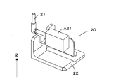
図3は図1の基板保持装置が基板の位置調整に用いる位置調整手段を示す斜視図である。位置調整手段20は、アライメントピン21の下端部を支持しつつアライメントピン21を水平方向へ駆動する位置調整アクチュエータA21と、位置調整アクチュエータA21をステージ11に固定するベース部材22とを有する。そして、位置調整アクチュエータA21がアライメントピン21を切り欠き部115に沿って進退させることで、載置面110上の基板Sの周縁に対して当接する当接位置P1(図9)と、載置面110上の基板Sの周縁から離間する離間位置P2(図9)との間でアライメントピン21が水平方向へ移動する。なお、位置調整アクチュエータA21としては例えばエアシリンダ、ソレノイド等の各種のものを使用できる。
FIG. 3 is a perspective view showing position adjustment means used by the substrate holding device of FIG. 1 for adjusting the position of the substrate. The position adjustment means 20 has a position
図1に示すように、複数のアライメントピン21は載置面110上の基板Sを四方から取り囲むように配置されている。そして、コントローラ10は、載置面110上における基板Sの載置領域の外側の離間位置P2に各アライメントピン21を退避させた状態で、リフトピン12によりロボットから載置面110へ基板Sを載置する。続いて、コントローラ10は、離間位置P2よりも基板Sの載置領域側の当接位置P1に各アライメントピン21を移動させる。こうして基板Sの各辺に対して複数(2個)のアライメントピン21が当接することで、載置面110に対してずれたり傾いたりして載置された基板Sの位置が、水平面内において適切に調整される。つまり、コントローラ10は、載置面110に基板Sが載置された状態で離間位置P2から当接位置P1へアライメントピン21を移動させることで載置面110上での基板Sの位置を調整する「位置調整処理」を実行する。
As shown in FIG. 1, the plurality of alignment pins 21 are arranged to surround the substrate S on the mounting
さらに、基板保持装置1は、載置面110上の基板Sを載置面110に押圧する押圧機構3を備える。この押圧機構3は、載置面110の各辺に1個ずつ配置された合計4個の押圧手段30を有し、各押圧手段30は、載置面110の対応する辺に沿って延設された押圧部材31を有する。そして、押圧手段30は、押圧アクチュエータA311〜A313により、載置面110上の基板Sの周縁部の直上に移動させた押圧部材31を降下させることで、基板Sを載置面110に押圧する。ちなみに、押圧部材31には、載置面110の対応する辺に設けられたアライメントピン21の進退方向に切り欠けられた切り欠き部32が設けられており、各切り欠き部32内にアライメントピン21が配置されている。かかる押圧部材31は、当接位置P1のアライメントピン21よりも載置面110上の基板S側へ水平方向に突出しつつ、基板Sの周縁部を載置面110に上方から押圧することが可能となっている。
Furthermore, the
図4は図1の基板保持装置が基板の押圧に用いる押圧手段とその周囲を示す斜視図である。図5は図1の基板保持装置が基板の押圧に用いる押圧手段とその周囲を示す側面図である。各押圧手段30の押圧部材31は、フレーム33と、フレーム33の下面に取り付けられた接触平板34とを有する。接触平板34は、載置面110の対応する辺に沿って水平方向へ延びるフレーム33の先端部の下面に、切り欠き部32を外して設けられており、その下部の接触平面35で載置面110上の基板Sの表面に接触する。
FIG. 4 is a perspective view showing pressing means used by the substrate holding device of FIG. 1 for pressing the substrate and the periphery thereof. FIG. 5 is a side view showing pressing means used by the substrate holding device of FIG. 1 for pressing the substrate and the periphery thereof. The pressing
また、各押圧手段30は、第1・第2押圧アクチュエータA311、A312を有し、第1押圧アクチュエータA311のロッドがL字板361を介して押圧部材31のフレーム33に取り付けられ、第2押圧アクチュエータA312のロッドがL字板362を介して第1押圧アクチュエータA311に取り付けられている。そして、第1押圧アクチュエータA311は押圧部材31を昇降駆動し、第2押圧アクチュエータA312は第1押圧アクチュエータA311を昇降駆動する。
Further, each pressing means 30 has first and second pressing actuators A311 and A312, the rod of the first pressing actuator A311 is attached to the
図4、図5では、各押圧アクチュエータA311、A312のロッドをそれぞれの昇降範囲の最下端に位置させており、押圧部材31はその昇降範囲の最下端である本押圧高さH1(図9)に位置する。この本押圧高さH1に位置する押圧部材31の接触平面35と載置面110との間隔は、基板Sの厚みに一致し、本押圧高さH1に位置する押圧部材31は、接触平面35により基板Sを載置面110に押圧することで、基板Sの形状を載置面110の形状(平面形状)に沿わせる。
In FIG. 4 and FIG. 5, the rods of the pressing actuators A311 and A312 are positioned at the lowermost end of the respective lifting and lowering ranges, and the pressing
また、第2押圧アクチュエータA312のロッドをその昇降範囲の最下端に位置させつつ、第1押圧アクチュエータA311のロッドをその昇降範囲の最上端に位置させると、押圧部材31はその昇降範囲の途中であって本押圧高さH1よりも高い仮押圧高さH2(図9)に位置し、押圧部材31の接触平面35はアライメントピン21の上端と載置面110との間に位置する。そして、基板Sの周縁部に一定以上の反りが生じている場合には、仮押圧高さH2に位置する押圧部材31の接触平面35により基板Sの周縁部を押圧して、基板Sの反りをある程度矯正できる。なお、仮押圧高さH2に位置する押圧部材31の接触平面35と載置面110との間隔は基板Sの厚みより広い。そのため、仮押圧高さH2に位置する押圧部材31の接触平面35により載置面110上の基板Sを押圧した状態では、基板Sは載置面110に対して水平方向に摺動可能であり、位置調整手段20による位置調整処理に応じて水平方向へ移動可能である。
When the rod of the first pressing actuator A 311 is positioned at the uppermost end of the lifting range while the rod of the second pressing actuator A 312 is positioned at the lowermost end of the lifting range, the pressing
さらに、各押圧アクチュエータA311、A312のロッドをそれぞれの昇降範囲の最上端に位置させると、押圧部材31はその昇降範囲の最上端であって仮押圧高さH2より高い退避高さH3(図9)に位置する。このように退避高さH3に位置する押圧部材31の接触平面35と載置面110との間隔は、想定される基板Sの反り量の最大値よりも広く設定されている。したがって、退避高さH3に位置する押圧部材31の接触平面35は、載置面110上の基板Sから離れる。
Further, when the rods of the pressing actuators A311 and A312 are positioned at the uppermost end of the respective lifting and lowering ranges, the pressing
また、各押圧手段30は、第2押圧アクチュエータA312を支持する移動プレート371と、移動プレート371をステージ11に対して水平方向に進退可能に支持するレール372と、レール372をステージ11に固定するベース部材373とを有する。さらに、押圧手段30は移動プレート371を駆動する第3押圧アクチュエータA313(図2)を有する。そして、第3押圧アクチュエータA313が移動プレート371をステージ11へ向けて進出させると、第2押圧アクチュエータA312が第1押圧アクチュエータA311および押圧部材31を伴って進出し、押圧部材31は載置面110における基板Sの載置領域の直上の進出位置L1(図9)に位置する。なお、図4、図5では押圧部材31は進出位置L1に位置している。一方、第3押圧アクチュエータA313が移動プレート371をステージ11から退避させると、第2押圧アクチュエータA312が第1押圧アクチュエータA311および押圧部材31を伴って退避し、押圧部材31は進出位置L1から基板Sの載置範囲の外側に外れた退避位置L2(図8)に位置する。
Further, each pressing means 30 fixes the moving
ちなみに、これら第1〜第3押圧アクチュエータA311〜A313としては、例えばエアシリンダ、ソレノイド等の各種のものを使用できる。 Incidentally, as these first to third pressing actuators A311 to A313, for example, various types of actuators such as an air cylinder and a solenoid can be used.
上記のような構成を備えた押圧機構3は、四角形の基板Sの異なる辺に対応して設けられた4個の押圧部材31のそれぞれに、基板Sの対応する辺に沿った範囲を押圧させる。また、基板Sの辺に沿った各押圧部材31の接触平面35の長さの合計は、基板Sの周長の3分の2以上となっている。したがって、4個の押圧部材31の全てを本押圧高さH1あるいは仮押圧高さH2に位置させることで、基板Sの周長の3分の2以上の範囲で基板Sの周縁部を押圧することができる。
The
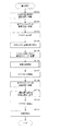
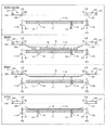
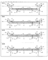
図6は図1の基板保持装置が実行する基板固定の一例を示すフローチャートである。図7は図1の基板保持装置が基板固定で実行する基板の仮押圧の手順を示すフローチャートである。図8および図9は図6および図7のフローチャートにより実行される動作を示す動作説明図である。なお、図8および図9では、押圧部材31の進出位置L1および退避位置L2は接触平板34の先端の位置で示され、押圧部材31の各高さH1〜H3は接触平面35の高さで示されている。
FIG. 6 is a flowchart showing an example of substrate fixing performed by the substrate holding device of FIG. FIG. 7 is a flow chart showing a procedure of temporary pressing of the substrate performed by the substrate holding apparatus of FIG. 1 in substrate fixing. FIG. 8 and FIG. 9 are operation explanatory diagrams showing the operation executed by the flowcharts of FIG. 6 and FIG. 8 and 9, the advanced position L1 and the retracted position L2 of the pressing
ステップS101では、載置面110の4辺それぞれに設けられた押圧部材31が退避高さH3に位置しつつ退避位置L2へ退避し、ステップS102では、各アライメントピン21が離間位置P2に位置する。その結果、図8の「S101〜S102」の欄に示す状態となる。この際、同欄に示すように、リフトピン12の上端はピン収納孔114内に収まっている。ロボットRが基板Sを載置面110の上方へ搬送してくると、各リフトピン12がピン収納孔114から上昇して各リフトピン12の上端が基板Sに当接し(ステップS103)、各リフトピン12がロボットRより基板Sを受け取る(ステップS104)。そして、各リフトピン12が降下して各リフトピン12の上端がピン収納孔114内に収まると、各リフトピン12の上端から載置面110に基板Sが載置される(ステップS105)。なお、図8の「S105」の欄に示すように、ここで示す例では、基板Sの周縁部が弓なりに反っており、基板Sの周縁が載置面110から離れている。
In step S101, the
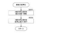
ステップS106では、基板Sの仮押圧が実行される。つまり、4個の押圧部材31が退避高さH3を維持しつつ進出位置L1に水平移動して基板Sの対応する辺の直上へ位置する(ステップS201)。続いて、4個の押圧部材31が退避高さH3から仮押圧高さH2にまで降下する(ステップS202)。図9の「S202」の欄に示すように、仮押圧高さH2に位置する押圧部材31が反りの生じた基板Sの周縁部を載置面110に向けて押圧することで、基板Sの反りがある程度矯正される。その結果、基板Sの周縁の高さは仮押圧高さH2以下に抑えられ、アライメントピン21の上端より低くなっている。
In step S106, temporary pressing of the substrate S is performed. That is, the four
基板Sの仮押圧が完了すると、エア供給部112がステージ11の通気孔から載置面110上の基板Sの下面にエアブローを開始する(ステップS107)。これによって、基板Sの下面が載置面110から僅かに離れて、基板Sの下面と載置面110との間の摩擦力の低下が図られる。ステップS108では、各アライメントピン21を当接位置P1へ移動させて、載置面110上での基板Sの位置が調整される(位置調整処理)。そして、位置調整処理が完了すると、4個の押圧部材31が本押圧高さH1に降下する(ステップS109)。図9の「S109」の欄に示すように、こうして本押圧高さH1に位置する押圧部材31により基板Sを載置面110に押圧することで、基板Sの形状が載置面110の形状に沿うように矯正される。
When the temporary pressing of the substrate S is completed, the
押圧部材31の本押圧高さH1への降下が完了すると、エア供給部112は基板Sへのエアブローを停止する(ステップS110)。そして、エア吸引部113が通気孔からエアを吸引することで、基板Sを載置面110に吸着する(ステップS111)。これによって、基板Sが載置面110に固定されて、図6のフローチャートが終了する。
When the lowering of the pressing
以上に説明したように第1実施形態では、押圧部材31は、ステージ11の載置面110上の基板Sを載置面110に押圧することで基板Sの形状を載置面110の形状に沿わせる本押圧高さH1と、本押圧高さH1よりも載置面110から離れて載置面110上の基板Sに対向する仮押圧高さH2とに選択的に位置することができる。そして、アライメントピン21を当接させることで載置面110上の基板Sの位置を調整する位置調整処理は、押圧部材31が仮押圧高さH2に位置した状態で実行される。したがって、載置面110に載置された基板Sの反りが大きい場合であっても、位置調整処理の実行の際には、仮押圧高さH2に位置する押圧部材31により基板Sの反りをある程度矯正することができる。その結果、ステージ11上での基板Sの位置調整に対する基板Sの反りの影響を抑制することが可能となっている。
As described above, in the first embodiment, the pressing
この際、位置調整処理は、基板Sの下面にエアがブローされた状態で実行される。これによって、基板Sと載置面110との間に生じる摩擦力を抑えて、位置調整処理における基板Sの位置調整をスムーズに行うことができる。
At this time, the position adjustment process is performed in a state where air is blown to the lower surface of the substrate S. By this, the frictional force generated between the substrate S and the mounting
また、位置調整機構2は、載置面110上の基板Sを取り囲むように配置された複数のアライメントピン21を、各アライメントピン21について設けられた離間位置P2から当接位置P1へ移動させることで位置調整処理を実行する。このように基板Sを取り囲む複数のアライメントピン21により位置調整処理を実行することで、載置面110上における基板Sの位置をより的確に調整することができる。
Further, the
また、基板Sの載置面110への吸着は、押圧部材31を本押圧高さH1に移動させた後に実行される。これによって、基板Sの周縁部を載置面110に密着させた状態で載置面110への基板Sの吸着を確実に実行することが可能となっている。
Further, the suction of the substrate S onto the
特にこの実施形態では、基板Sの反りの影響を抑えつつ基板Sの位置調整を実行することで、ステージ11上の基板Sと各押圧部材31との位置ずれを効果的に抑制可能となっている。その結果、位置調整処理後に実行される基板Sの押圧矯正(ステップS109)において、各押圧部材31を対応する基板Sの周縁部に的確に接触させて、基板Sの形状を載置面110の形状にしっかりと沿わせることができる。さらには、基板Sの吸着(ステップS111)を載置面110に基板Sを密着させた状態で実行できるため、基板Sの吸着を確実に実行して、基板Sをステージ11にしっかりと固定することができる。
Particularly in this embodiment, by performing the position adjustment of the substrate S while suppressing the influence of the warp of the substrate S, the positional deviation between the substrate S on the
また、押圧機構3は、基板Sの周長の3分の2以上の範囲で基板Sの周縁部を、本押圧高さH1に位置する押圧部材31により押圧する。これによって、基板Sの形状を載置面110の形状にしっかりと沿わせて、基板Sの形状をより確実に矯正することができる。
Further, the
また、押圧部材31は、その接触平面35で載置面110上の基板Sに接触する。そして、仮押圧高さH2に位置する押圧部材31の接触平面35がアライメントピン21の上端と載置面110との間に位置するように、仮押圧高さH2が設定されている。したがって、基板Sが仮押圧された状態で実行される位置調整処理では、基板Sの周縁がアライメントピン21の上端より低く抑えられており、基板Sの周縁にアライメントピン21を確実に当接させることができる。その結果、ステージ11上での基板Sの位置調整に対する基板Sの反りの影響をより確実に抑制することが可能となっている。
The pressing
また、押圧機構3は、複数の押圧部材31により基板Sの表面の異なる範囲(各辺に沿った範囲)を押圧する。これによって、基板Sの反りを比較的均一に矯正することが可能となっている。
Further, the
図10は本発明の第2実施形態に係る基板保持装置を示す側面図である。図11は図10の基板保持装置を示す正面図である。図12は図10の基板保持装置が備える電気的構成を示すブロック図である。第2実施形態が第1実施形態と異なるのは、各押圧部材31を仮押圧高さH2に降下させる順序を基板Sの反り量を取得した結果に基づき決定する点にある。そこで、以下では第1実施形態との差異部分を中心に説明し、共通部分については相当符号を付して説明を省略する。ただし、第1実施形態と共通する構成を備えることで、第2実施形態においても同様の効果が奏されることは言うまでもない。
FIG. 10 is a side view showing a substrate holding apparatus according to a second embodiment of the present invention. FIG. 11 is a front view showing the substrate holding device of FIG. FIG. 12 is a block diagram showing an electrical configuration of the substrate holding apparatus of FIG. The second embodiment differs from the first embodiment in that the order in which the
第2実施形態の基板保持装置1は、作業者に報知を行う報知部119と、基板Sの反りを検出する反り検出機構4とを、第1実施形態の基板保持装置1に追加した構成を具備する。報知部119は、例えば液晶ディスプレイ等の表示装置で構成され、表示装置の画面に所定の文字や画像を表示することで作業者への報知を行う。なお、報知部119の具体的な構成はこの例に限られず、音あるいは光等により作業者に報知を行うように報知部119を構成することもできる。
The
反り検出機構4は、Y方向に並ぶ複数の距離センサ41と、これら距離センサ41を載置面110の上方で支持するブリッジ構造のセンサ支持部45とを有する。距離センサ41は例えばレーザ変位計等であり、載置面110に載置された基板Sの表面に上方から対向する。センサ支持部45は、載置面110における基板Sの載置範囲のY方向の両側で載置面110から上方へ立設する2本の柱部材451と、載置面110の上方でこれら柱部材451の間に掛け渡された梁部材452とを有する。梁部材452はY方向に平行に延設されており、複数の距離センサ41はY方向において互いに異なる位置で梁部材452に取り付けられている。
The
こうしてセンサ支持部45に支持された複数の距離センサ41は、基板SのうちY方向において互いに異なる位置を計測対象位置とする。特に、ここで示す例では、3個の距離センサ41のうち、両端の距離センサ41が基板SのY方向の周縁部を計測対象位置とし、中央の距離センサ41が基板SのY方向の中央部を計測対象位置とする。
The plurality of
さらに、反り検出機構4は各距離センサ41を伴ってセンサ支持部45をステージ11に対してX方向に移動させる走査駆動部47を有する。この走査駆動部47は例えばリニアモータ等で構成されており、コントローラ10からの指令に従ってセンサ支持部45をX方向に移動させることで、載置面110上の基板Sの表面に対して各距離センサ41の計測対象位置をX方向に走査する。
Furthermore, the
そして、コントローラ10は、各距離センサ41の計測結果に基づき、基板Sの各辺の反り量を算出する。具体的には、載置面110の高さが各距離センサ41により予め基準高さとして計測されて、コントローラ10に保存されている。そして、コントローラ10は、走査駆動部47により各距離センサ41をX方向へ移動させつつ各距離センサ41の計測結果を各距離センサ41の位置座標(XY座標)と対応付けて取得することで、基板Sの表面の異なる位置の高さを計測する。この際、各距離センサ41の計測対象位置は、基板Sの表面をX方向の全域に渡って走査する。続いて、コントローラ10は、基板Sの表面の高さと基準高さとの差を、基板Sの表面の異なる位置それぞれについて算出することで、基板Sの表面形状、換言すれば基板Sの反りの状態を推定する。そして、コントローラ10は、基板Sの反りの状態の推定結果に基づき、基板Sの4辺それぞれの載置面110からの高さを、各辺の反りの程度を示す値、すなわち反り量として算出する。
Then, the
そして、第2実施形態においても、図6のフローチャートを実行することで、基板Sをステージ11に固定する。特に第2実施形態では、次に示すように、図6のステップS106で各押圧部材31を仮押圧高さH2に降下させる順序が基板Sの反り量を検出した結果に基づき決定される。
Then, also in the second embodiment, the substrate S is fixed to the
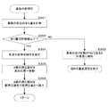
図13は図10の基板保持装置が基板固定で実行する基板の仮押圧の手順を示すフローチャートである。ステップS301では、上述の要領で基板Sの各辺の反り量が検出される。そして、ステップS302において、基板Sの各辺の反り量がいずれも許容値以下であるかが判断される。基板Sの4辺のうちに反り量が許容値より大きい辺がある場合(ステップS302で「NO」の場合)には、基板Sの反り状態が不良であるとの内容が報知部119の画面に表示され(ステップS303)、図6のフローチャートが終了する。 FIG. 13 is a flow chart showing a procedure of temporary pressing of the substrate performed by the substrate holding apparatus of FIG. 10 in substrate fixing. In step S301, the amount of warpage of each side of the substrate S is detected as described above. Then, in step S302, it is determined whether the amount of warpage of each side of the substrate S is equal to or less than the allowable value. When there is a side where the amount of warping is larger than the allowable value among the four sides of the substrate S (in the case of “NO” in step S302), the content that the warping state of the substrate S is defective is the screen of the notification unit 119 (Step S303), and the flowchart of FIG. 6 ends.
ここで、許容値の具体的な値としては種々考えられる。例えば、良品の基板Sに求められる反り量の最大値を許容値としても良い。あるいは、押圧部材31の退避高さH3に対して許容値を設定しても良い。つまり、退避高さH3に位置する押圧部材31の接触平面35と基板Sとの干渉が発生する値よりも小さい値を許容値とする。これによって、押圧部材31を退避位置L2から進出位置L1に移動させた際に、基板Sの反りが大きいために押圧部材31と基板Sとが干渉するのを抑制することができる。
Here, various specific values of the allowable value can be considered. For example, the maximum value of the amount of warpage required for the non-defective substrate S may be used as the allowable value. Alternatively, the allowable value may be set for the retraction height H3 of the pressing
一方、基板Sの4辺の全てについて反り量が許容値以下である場合(ステップS302で「YES」の場合)には、押圧部材31を退避高さH3から載置面110上の基板Sへ向けて移動させて仮押圧高さH2に位置させる仮押圧動作を各押圧部材31に実行させる順序、すなわち仮押圧順序が、基板Sの各辺の反り量に基づき決定される(ステップS304)。具体的には、基板Sの4辺のうち反り量が最大となる特定辺を特定し、この特定辺に対応する押圧部材31に1番目に仮押圧動作を実行させると決定する。また、特定辺の対辺に対応する押圧部材31に2番目に仮押圧動作を実行させると決定する。続いて、特定辺とその対辺とは異なる他の2辺のうち、反り量が大きい方の辺に対応する押圧部材31に3番目に仮押圧動作を実行させ、反り量が小さい方の辺に対応する押圧部材31に4番目に仮押圧動作を実行させると決定する。
On the other hand, if the warpage amount is less than the allowable value for all four sides of the substrate S (in the case of “YES” in step S302), the pressing
こうして、仮押圧順序が決定すると、4個の押圧部材31が退避高さH3を維持しつつ進出位置L1に水平移動して基板Sの対応する辺の直上へ位置する(ステップS305)。続いて、4個の押圧部材31がステップS304で決定された仮押圧順序に従って順番に仮押圧高さH2へ降下し、仮押圧動作を実行する(ステップS306)。こうして、基板Sの4辺の全てに対して仮押圧動作が実行されると、図13のフローチャートを終了して、図6のフローチャートへ戻る。
Thus, when the temporary pressing order is determined, the four
このように第2実施形態では、載置面110に載置された基板Sの表面と載置面110との間隔に応じた値を示す反り量(指標値)が基板Sの表面の異なる部分について取得される。そして、押圧部材31を載置面110上の基板Sへ向けて移動させて仮押圧高さH2に位置させる仮押圧動作を各押圧部材31に実行させる仮押圧順序が基板Sの反り量に基づいて決定され、各押圧部材31はこの仮押圧順序に従って仮押圧動作を実行する。これによって、基板Sの反り方に応じた順序で各押圧部材31を仮押圧高さH2に位置させて、基板Sの反りを比較的均一に矯正することができる。その結果、載置面110上での基板Sの位置調整に対する基板Sの反りの影響をより確実に抑制可能となる。
As described above, in the second embodiment, the warpage amount (index value) indicating a value corresponding to the distance between the surface of the substrate S mounted on the mounting
また、反り量が取得された基板Sの表面の4辺(部分)のうち、反り量が最大となる特定辺(特定部分)が特定され、4個の押圧部材31のうち特定辺に最近接の範囲を押圧する押圧部材31を含む一部の押圧部材31が、当該一部の押圧部材31とは異なる他の押圧部材31より先に仮押圧動作を実行する。これによって、基板Sの4辺のうち反りの大きい辺から優先して矯正されるため、基板Sの反りを比較的均一に矯正することができる。
Further, among the four sides (portions) of the surface of the substrate S for which the amount of warpage has been acquired, a specific side (specific part) at which the amount of warpage is largest is specified, and the closest side to the specific side of the four pressing members 31 A part of the pressing
ちなみに、ステップS304で仮押圧順序を決定する具体的態様は、上述の例に限られない。例えば、特定辺およびその対辺に対応する2個の押圧部材31に同時に仮押圧動作を実行させた後に、特定辺およびその対辺と異なる他の2辺に対応する2個の押圧部材31に仮押圧動作を同時に実行させると決定しても良い。あるいは、対応する辺の反り量が大きい押圧部材31から順番に仮押圧動作を実行させると決定しても良い。
Incidentally, the specific mode of determining the temporary pressing order in step S304 is not limited to the above-described example. For example, after temporary pressing operation is simultaneously performed on two
ところで、上述の基板保持装置1は、基板Sに対して処理を行う種々の基板処理装置に適用可能である。例えば次に説明するように、塗布液を塗布する塗布処理を基板Sに対して実行する塗布装置に基板保持装置1を装備することもできる。
By the way, the above-mentioned
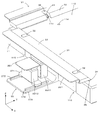
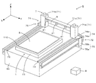
図14は本発明に係る塗布装置の一例を示す斜視図である。塗布装置5は、スリットノズル6を用いて基板Sの表面に塗布液を塗布するスリットコータと呼ばれる塗布装置である。塗布液としては、レジスト液、カラーフィルター用液、ポリイミド、シリコン、ナノメタルインク、導電性材料を含むスラリー等、種々のものを用いることが可能である。この塗布装置5は、基台50と、基台50の上に配置された基板保持装置1と、基板保持装置1のステージ11に保持される基板Sにスリットノズル6を用いて塗布処理を施す塗布処理部7と、これら各部を制御するコントローラ8とを備える。この塗布装置5が備える基板保持装置1は第2実施形態の基板保持装置1と同様の構成を備えており、上述のコントローラ10の機能がコントローラ8に内蔵されている。
FIG. 14 is a perspective view showing an example of a coating apparatus according to the present invention. The
スリットノズル6はY方向に延びる長尺状の開口部である吐出口を有しており、ステージ11に保持された基板Sの表面に向けて吐出口から塗布液を吐出可能である。塗布装置5では、スリットノズル6をX方向に移動させる移動機構が塗布処理部7に設けられており、ステージ11の載置面110の上方でスリットノズル6をX方向に往復移動させることができる。そして、載置面110の上方をX方向に移動するスリットノズル6から吐出された塗布液が、載置面110上の基板Sの表面に塗布される。
The
塗布処理部7の移動機構は、ステージ11の上方をY方向に横断しスリットノズル6を支持するブリッジ構造のノズル支持体71と、ノズル支持体71をX方向に水平移動させるスリットノズル移動部72とを有する。したがって、ノズル支持体71に支持されたスリットノズル6をスリットノズル移動部72によってX方向に水平移動させることができる。
The moving mechanism of the
ノズル支持体71は、スリットノズル6が固定された固定部材71aと、固定部材71aを支持しつつ昇降させる2つの昇降機構71bとを有している。固定部材71aは、Y方向を長手方向とする断面矩形の棒状部材であり、カーボンファイバ補強樹脂等で構成される。2つの昇降機構71bは固定部材71aの長手方向の両端部に連結されており、それぞれACサーボモータおよびボールネジ等を有する。これらの昇降機構71bにより、固定部材71aとスリットノズル6とが一体的に鉛直方向(Z方向)に昇降され、スリットノズル6の吐出口と基板Sのとの間隔、すなわち、基板Sの表面に対する吐出口の相対的な高さが調整される。
The
スリットノズル移動部72は、スリットノズル6の移動をX方向に案内する2本のガイドレール73と、駆動源である2個のリニアモータ74と、スリットノズル6の吐出口の位置を検出するための2個のリニアエンコーダ75とを備えている。
The slit
2本のガイドレール73は、基板Sの載置範囲をY方向から挟むように基台50のY方向の両端に配置されるとともに、基板Sの載置範囲を含むようにX方向に延設されている。そして、2つの昇降機構71bの下端部のそれぞれが2本のガイドレール73に沿って案内されることで、スリットノズル6がステージ11上に保持される基板Sの上方をX方向へ移動する。
The two
2個のリニアモータ74のそれぞれは、固定子74aと移動子74bとを有するACコアレスリニアモータである。固定子74aは、基台50のY方向の両側面にX方向に沿って設けられている。一方、移動子74bは、昇降機構71bの外側に対して固設されている。リニアモータ74は、これら固定子74aと移動子74bとの間に生じる磁力によって、スリットノズル移動部72の駆動源として機能する。
Each of the two
また、2個のリニアエンコーダ75のそれぞれは、スケール部75aと検出部75bとを有している。スケール部75aは基台50に固設されたリニアモータ74の固定子74aの下部にX方向に沿って設けられている。一方、検出部75bは、昇降機構71bに固設されたリニアモータ74の移動子74bのさらに外側に固設され、スケール部75aに対向配置される。リニアエンコーダ75は、スケール部75aと検出部75bとの相対的な位置関係に基づいて、X方向におけるスリットノズル6の吐出口の位置を検出する。
Each of the two
つまり、塗布処理部7は、昇降機構71bによりスリットノズル6と基板Sとの間隔をZ方向に調整しつつ、スリットノズル移動部72によりスリットノズル6を基板Sに対してX方向に相対移動させることができる。そして、X方向に移動するスリットノズル6から塗布液を吐出することで基板Sの表面に塗布液を塗布することができる。
That is, the
そして、塗布処理部7の駆動機構を構成するノズル支持体71の固定部材71aに、3個の距離センサ41がY方向に並んで取り付けられており、ノズル支持体71が上述のセンサ支持部45の役割を果たし、リニアモータ74が上述の走査駆動部47の役割を果たす。したがって、コントローラ8は、上述の同じ要領で図6および図13のフローチャートを実行して、基板Sをステージ11に固定することができる。
Then, three
ちなみに、ここでは第2実施形態の基板保持装置1を塗布装置5に装備した場合を例示したが、第1実施形態の基板保持装置1を塗布装置5に装備することもできる。この場合には、図14の塗布装置5から各距離センサ41を省略することができる。
Incidentally, although the case where the
以上に説明したように、上記実施形態においては、基板保持装置1が本発明の「基板保持装置」の一例に相当し、ステージ11が本発明の「載置台」の一例に相当し、載置面110が本発明の「載置面」の一例に相当し、位置調整機構2が本発明の「位置調整機構」の一例に相当し、アライメントピン21が本発明の「位置調整部材」の一例に相当し、当接位置P1が本発明の「当接位置」の一例に相当し、離間位置P2が本発明の「離間位置」の一例に相当し、押圧機構3が本発明の「押圧機構」の一例に相当し、押圧部材31が本発明の「押圧部材」の一例に相当し、接触平面35が本発明の「接触面」の一例に相当し、本押圧高さH1が本発明の「本押圧位置」の一例に相当し、仮押圧高さH2が本発明の「仮押圧位置」の一例に相当し、エア供給部112が本発明の「ガスブロー機構」の一例に相当し、エア吸引部113が本発明の「吸着機構」の一例に相当し、通気孔が本発明の「ブロー孔」および「吸着孔」の一例に相当し、塗布装置5が本発明の「塗布装置」の一例に相当し、スリットノズル6が本発明の「ノズル」の一例に相当し、基板Sが本発明の「基板」の一例に相当する。
As described above, in the above embodiment, the
なお、本発明は上記した実施形態に限定されるものではなく、その趣旨を逸脱しない限りにおいて上述したもの以外に種々の変更を行うことが可能である。例えば基板Sの反り量の具体的な検出方法は上述の内容に限られず、種々の変更が可能である。具体的には、基板Sの中央部は反りが無いか、反りが有っても僅少であることを利用して、基板Sの中央の高さを基準高さとして距離センサ41により計測しても良い。この場合、基板Sの表面の高さと基準高さとの差を、基板Sの反りの程度を示す反り量(指標値)として基板Sの表面の異なる位置について算出することで、基板Sの反りの状態を推定できる。
The present invention is not limited to the above-described embodiment, and various modifications can be made other than the above without departing from the scope of the invention. For example, the specific detection method of the amount of warpage of the substrate S is not limited to the above-described content, and various modifications are possible. Specifically, by using the fact that the central portion of the substrate S is not warped or the amount of warping is small, the height of the center of the substrate S is measured by the
また、基板Sの反り量は距離センサ41を用いて計測することで取得されていた。しかしながら、例えば基板Sの反り量(指標値)を示すデータが予め用意されているような場合には、コントローラ10が当該データを読み込むことで基板Sの反り量を取得しても良い。
In addition, the amount of warpage of the substrate S is obtained by measuring using the
また、上記の仮押圧高さH2の具体的な値についても適宜調整が可能である。そこで、仮押圧高さH2の最適値を実験的に予め求めておいても良い。つまり、仮押圧高さH2を変更しつつ位置調整処理を実験的に行った結果、位置調整処理に最も適すると判断できる値に仮押圧高さH2を設定しても良い。 Further, the specific value of the above-described temporary pressing height H2 can be appropriately adjusted. Therefore, the optimum value of the temporary pressing height H2 may be experimentally obtained in advance. That is, as a result of experimentally performing the position adjustment process while changing the temporary press height H2, the temporary press height H2 may be set to a value that can be determined to be most suitable for the position adjustment process.
また、2個のアクチュエータA311、A312を組み合わせて押圧手段30を構成していた。しかしながら、単一のソレノイド等で押圧手段30を構成しても構わない。 Further, the pressing means 30 is configured by combining two actuators A311 and A312. However, the pressing means 30 may be configured by a single solenoid or the like.
また、上記実施形態では、各押圧部材31は、対応する辺に平行な方向へ長尺な形状を有していた。しかしながら、押圧部材31の形状はこれに限られず、例えばピン形状を有する押圧部材31によって基板Sを上方から載置面110に押圧するように構成しても良い。
Moreover, in the said embodiment, each pressing
特に第1実施形態の基板保持装置1を構成するにあたっては、基板Sの辺毎に押圧部材31を別体で設ける必要はなく、中空の四画形状を有するフレームで押圧部材31を一体的に構成しても構わない。
In particular, in forming the
また、基板保持装置1の保持対象となる基板Sの形状は上記の四角形に限られず、他の形状を有する基板Sを保持するにあたって上述の技術を適用することができる。例えば、一部の隅を切り欠いたオリエンテーションフラットを設けた四角形状の基板Sや、周縁の一部を切り欠いたオリエンテーションフラットを設けた円形状の基板Sを保持するために上述の技術を用いても良い。
Further, the shape of the substrate S to be held by the
また、スリットノズル6により塗布液を塗布する塗布装置5を用いて説明を行った。しかしながら、ノズルはスリットタイプに限定されるものではなく、従来周知の異なるタイプのノズルを用いることができる。
Further, the description has been made using the
また、塗布装置5は、スリットノズル6を移動させることでスリットノズル6を基板Sに対して相対移動させていた。しかしながら、基板保持装置1を所定方向に駆動することで、スリットノズル6を基板Sに対して相対移動させる装置に対しても、上述の基板保持装置1の構成を装備できる。
The
以上、具体的な実施形態を例示して説明してきたように、本発明では例えば次のように構成することができる。 As described above, the present invention can be configured, for example, as follows as exemplified and described in the specific embodiments.
つまり、載置面で開口するブロー孔から載置面上の基板へガスをブローするガスブロー機構をさらに備え、制御部は、ガスブロー機構に基板へガスをブローさせつつ位置調整機構に位置調整処理を実行させるように、基板保持装置を構成しても良い。これによって、基板と載置面との間に生じる摩擦力を抑えて、位置調整処理における基板の位置調整をスムーズに行うことができる。 That is, the control unit further includes a gas blow mechanism for blowing gas from the blow holes opened at the placement surface to the substrate on the placement surface, and the control unit causes the position adjustment mechanism to perform position adjustment processing while causing the gas blow mechanism to blow gas to the substrate. The substrate holding device may be configured to perform. By this, the frictional force generated between the substrate and the mounting surface can be suppressed, and the position adjustment of the substrate in the position adjustment process can be smoothly performed.
また、位置調整機構は、載置面上の基板を取り囲むように配置された複数の位置調整部材を、各位置調整部材について設けられた離間位置から当接位置へ移動させることで位置調整処理を実行するように、基板保持装置を構成しても良い。このように基板を取り囲む複数の位置調整部材により位置調整処理を実行することで、載置面上における基板の位置をより的確に調整することができる。 In addition, the position adjustment mechanism moves the position adjustment process by moving the plurality of position adjustment members arranged to surround the substrate on the mounting surface from the separated position provided for each position adjustment member to the abutting position. The substrate holding device may be configured to perform. By performing the position adjustment process using the plurality of position adjustment members that surround the substrate as described above, the position of the substrate on the mounting surface can be more accurately adjusted.
また、載置面に開口する吸着孔からガスを吸引することで載置面上の基板を載置面に吸着する吸着機構をさらに備え、制御部は、押圧部材を本押圧位置に移動させた後に、吸着機構に基板を吸着させるように、基板保持装置を構成しても良い。これによって、基板を載置面に密着させた状態で載置面への基板の吸着を確実に実行することができる。 Further, the apparatus further comprises an adsorption mechanism for adsorbing the substrate on the mounting surface to the mounting surface by suctioning gas from the suction holes opened in the mounting surface, and the control unit moves the pressing member to the main pressing position. The substrate holding device may be configured to cause the suction mechanism to suction the substrate later. In this way, it is possible to reliably perform the suction of the substrate onto the mounting surface in a state where the substrate is in close contact with the mounting surface.
この際、吸着孔をブロー孔に兼用することもできる。具体的には、吸着孔に対してガスの吸引とガスのブローとを切り換えて実行すれば良い。 At this time, the suction holes can also be used as blow holes. Specifically, the suction of the gas and the blow of the gas may be switched to the adsorption holes and executed.
また、押圧機構は、基板の周長の3分の2以上の範囲で基板の周縁部を押圧部材により押圧するように、基板保持装置を構成しても良い。これによって、基板の形状を載置面の形状にしっかりと沿わせて、基板の形状をより確実に矯正することができる。 Further, the pressing mechanism may configure the substrate holding device such that the peripheral portion of the substrate is pressed by the pressing member within a range of two thirds or more of the circumferential length of the substrate. By this, the shape of the substrate can be made to conform to the shape of the mounting surface firmly, and the shape of the substrate can be corrected more reliably.
また、押圧部材は、その接触面で載置面上の基板に接触し、位置調整部材は、載置面から突出するように設けられ、位置調整部材の載置面から突出した先端と載置面との間に、仮押圧位置に位置する押圧部材の接触面が位置するように、基板保持装置を構成しても良い。これによって、載置台上での基板の位置調整に対する基板の反りの影響をより確実に抑制することが可能となる。 Further, the pressing member is in contact with the substrate on the mounting surface at the contact surface, and the position adjusting member is provided so as to project from the mounting surface, and the tip and the mounting protruding from the mounting surface of the position adjusting member The substrate holding device may be configured such that the contact surface of the pressing member located at the temporary pressing position is located between the surface and the surface. This makes it possible to more reliably suppress the influence of the warp of the substrate on the adjustment of the position of the substrate on the mounting table.
また、押圧機構は、複数の押圧部材により基板の表面の異なる範囲を押圧するように、基板保持装置を構成しても良い。これによって、基板の反りを比較的均一に矯正することができる。 Further, the pressing mechanism may configure the substrate holding device so as to press different ranges of the surface of the substrate by a plurality of pressing members. Thereby, the warp of the substrate can be relatively uniformly corrected.
また、載置面に載置された基板の表面と載置面との間隔に応じた値を示す指標値を基板の表面の異なる部分について取得する取得部をさらに備え、制御部は、押圧部材を載置面上の基板へ向けて移動させて仮押圧位置に位置させる仮押圧動作を各押圧部材に実行させる順序を指標値に基づいて決定し、当該順序で各押圧部材に仮押圧動作を実行させるように、基板保持装置を構成しても良い。これによって、基板の反り方に応じた順序で各押圧部材を仮押圧位置に位置させて、基板の反りを比較的均一に矯正することができる。その結果、載置台上での基板の位置調整に対する基板の反りの影響をより確実に抑制可能となる。 The control unit further includes an acquisition unit for acquiring, for different portions of the surface of the substrate, an index value indicating a value according to the distance between the surface of the substrate and the surface of the substrate mounted on the mounting surface, and the control unit Is determined based on the index value in the order in which each pressing member is caused to perform the temporary pressing operation in which the pressing member is moved toward the substrate on the mounting surface and positioned at the temporary pressing position. The substrate holding device may be configured to perform. By this, the pressing members can be positioned at the temporary pressing positions in the order according to the warping of the substrate, and the warping of the substrate can be corrected relatively uniformly. As a result, the influence of the warp of the substrate on the adjustment of the position of the substrate on the mounting table can be suppressed more reliably.
また、制御部は、指標値が取得された基板の表面の各部分のうち、指標値が最大となる特定部分を特定し、複数の押圧部材のうち特定部分に最近接の範囲を押圧する押圧部材を含む一部の押圧部材に、当該一部の押圧部材とは異なる他の押圧部材より先に仮押圧動作を実行させると決定するように、基板保持装置を構成しても良い。これによって、基板のうち反りの大きい部分から優先して矯正されるため、基板の反りを比較的均一に矯正することができる。 In addition, the control unit identifies a specific portion where the index value is maximum among the portions of the surface of the substrate for which the index value is acquired, and presses the range closest to the specific portion among the plurality of pressing members. The substrate holding device may be configured to determine that the partial pressing member including the member is to perform the temporary pressing operation earlier than the other pressing member different from the partial pressing member. As a result, since the correction is given priority from the portion of the substrate with the largest warpage, the warpage of the substrate can be relatively uniformly corrected.
具体的には、基板の形状は四角形状であり、押圧機構は、基板の異なる辺に対応して設けられた4個の押圧部材のそれぞれに、基板の対応する辺に沿った範囲を押圧させ、制御部は、基板の4辺のうち指標値が最大となる特定辺を特定部分として特定し、4個の押圧部材のうち、特定辺および特定辺の対辺に対応する2個の押圧部材に、当該2個の押圧部材とは異なる他の押圧部材より先に仮押圧動作を実行させると決定するように、基板保持装置を構成しても良い。これによって、基板のうち反りの大きい辺から優先して矯正されるため、基板の反りを比較的均一に矯正することができる。 Specifically, the shape of the substrate is a square, and the pressing mechanism causes the four pressing members provided corresponding to different sides of the substrate to press a range along the corresponding side of the substrate. The control unit specifies a specific side having the largest index value among the four sides of the substrate as a specific part, and of the four pressing members, the two pressing members corresponding to the specific side and the opposite side of the specific side. The substrate holding device may be configured to determine that the temporary pressing operation is to be performed earlier than another pressing member different from the two pressing members. As a result, since the correction is given priority from the side of the substrate having the largest warpage, the warpage of the substrate can be relatively uniformly corrected.
この発明は、基板を載置台に保持する基板保持技術全般に適用することができ、特に基板に塗布液を塗布するために基板を載置台に保持する塗布装置に好適に適用することができる。 The present invention can be applied generally to substrate holding techniques for holding a substrate on a mounting table, and in particular, can be suitably applied to a coating apparatus for holding a substrate on a mounting table in order to apply a coating liquid to the substrate.
1…基板保持装置
11…ステージ
110…載置面
2…位置調整機構
21…アライメントピン
P1…当接位置
P2…離間位置
3…押圧機構
31…押圧部材
32…切り欠き部
33…フレーム
34…接触平板
35…接触平面
H1…本押圧高さ
H2…仮押圧高さ
L1…進出位置
L2…退避位置
112…エア供給部
113…エア吸引部
5…塗布装置
6…スリットノズル
S…基板
DESCRIPTION OF
Claims (12)
前記載置面上の前記基板の周縁に対して当接する当接位置と離間する離間位置との間で移動可能な位置調整部材を、前記載置面に前記基板が載置された状態で前記離間位置から前記当接位置へ移動させることで前記載置面上での前記基板の位置を調整する位置調整処理を実行する位置調整機構と、
前記載置面上の前記基板を前記載置面に押圧することで前記基板の形状を前記載置面の形状に沿わせる本押圧位置と、前記本押圧位置よりも前記載置面から離れて前記載置面上の前記基板に対向する仮押圧位置とに選択的に押圧部材を位置させる押圧機構と、
前記位置調整部材を前記離間位置に位置させつつ前記押圧部材を前記載置面上の前記基板へ向けて移動させて前記仮押圧位置に位置させてから前記位置調整機構に前記位置調整処理を実行させ、前記位置調整処理の完了後に前記押圧部材を前記本押圧位置に移動させる制御部と
を備える基板保持装置。 A mounting table on which the substrate is mounted on the mounting surface;
A position adjusting member movable between an abutting position abutted against the peripheral edge of the substrate on the mounting surface and a separated position separated from the substrate in a state where the substrate is mounted on the mounting surface; A position adjustment mechanism that executes a position adjustment process of adjusting the position of the substrate on the mounting surface by moving from the separation position to the contact position;
The main pressing position, which causes the shape of the substrate to conform to the shape of the mounting surface by pressing the substrate on the mounting surface against the mounting surface, and the main pressing position is further from the mounting surface than the main pressing position A pressing mechanism for selectively positioning a pressing member at a temporary pressing position facing the substrate on the mounting surface;
The position adjustment process is performed on the position adjustment mechanism after the pressure adjustment member is moved to the substrate on the placement surface while the position adjustment member is positioned at the separated position to be positioned at the temporary press position. A control unit for moving the pressing member to the main pressing position after completion of the position adjustment process.
前記載置面で開口するブロー孔から前記載置面上の前記基板へガスをブローするガスブロー機構をさらに備え、
前記制御部は、前記ガスブロー機構に前記基板へガスをブローさせつつ前記位置調整機構に前記位置調整処理を実行させる基板保持装置。 The substrate holding device according to claim 1, wherein
The apparatus further comprises a gas blowing mechanism for blowing a gas from the blow holes opened at the mounting surface to the substrate on the mounting surface,
The control unit causes the position adjustment mechanism to execute the position adjustment process while causing the gas blow mechanism to blow the gas to the substrate.
前記位置調整機構は、前記載置面上の前記基板を取り囲むように配置された複数の前記位置調整部材を、前記各位置調整部材について設けられた前記離間位置から前記当接位置へ移動させることで前記位置調整処理を実行する基板保持装置。 The substrate holding device according to claim 1 or 2, wherein
The position adjusting mechanism moves a plurality of the position adjusting members arranged to surround the substrate on the mounting surface from the spaced position provided for each of the position adjusting members to the contact position. A substrate holding device for executing the position adjustment process.
前記載置面に開口する吸着孔からガスを吸引することで前記載置面上の前記基板を前記載置面に吸着する吸着機構をさらに備え、
前記制御部は、前記押圧部材を前記本押圧位置に移動させた後に、前記吸着機構に前記基板を吸着させる基板保持装置。 The substrate holding device according to any one of claims 1 to 3, wherein
The apparatus further comprises an adsorption mechanism for adsorbing the substrate on the mounting surface to the mounting surface by sucking a gas from adsorption holes opened to the mounting surface,
The said control part is a substrate holding apparatus which makes the said adsorption | suction mechanism adsorb | suck the said board | substrate, after moving the said press member to the said main press position.
前記押圧機構は、前記基板の周長の3分の2以上の範囲で前記基板の周縁部を前記押圧部材により押圧する基板保持装置。 The substrate holding device according to any one of claims 1 to 4, wherein
The said holding | pressing mechanism is a board | substrate holding apparatus which presses the peripheral part of the said board | substrate by the said pressing member in 2/3 or more of the circumferential length of the said board | substrate.
前記押圧部材は、その接触面で前記載置面上の前記基板に接触し、
前記位置調整部材は、前記載置面から突出するように設けられ、
前記位置調整部材の前記載置面から突出した先端と前記載置面との間に、前記仮押圧位置に位置する前記押圧部材の接触面が位置する基板保持装置。 The substrate holding device according to any one of claims 1 to 5, wherein
The pressing member contacts the substrate on the mounting surface at the contact surface,
The position adjusting member is provided to project from the mounting surface,
A substrate holding device, wherein a contact surface of the pressing member positioned at the temporary pressing position is located between a tip of the position adjustment member protruding from the placement surface and the placement surface.
前記押圧機構は、複数の前記押圧部材により前記基板の表面の異なる範囲を押圧する基板保持装置。 The substrate holding device according to any one of claims 1 to 6, wherein
The substrate holding device, wherein the pressing mechanism presses different ranges of the surface of the substrate by a plurality of the pressing members.
前記載置面に載置された前記基板の表面と前記載置面との間隔に応じた値を示す指標値を前記基板の表面の異なる部分について取得する取得部をさらに備え、
前記制御部は、前記押圧部材を前記載置面上の前記基板へ向けて移動させて前記仮押圧位置に位置させる仮押圧動作を前記各押圧部材に実行させる順序を前記指標値に基づいて決定し、当該順序で前記各押圧部材に前記仮押圧動作を実行させる基板保持装置。 The substrate holding device according to claim 7, wherein
An acquisition unit is further provided for acquiring, for different portions of the surface of the substrate, an index value indicating a value according to the distance between the front surface of the substrate and the front surface of the substrate mounted on the mounting surface,
The control unit determines, based on the index value, the order in which the pressing members are caused to move the pressing members toward the substrate on the placement surface to position the temporary pressing position on the temporary pressing position. And the substrate holding device which causes the pressing members to perform the temporary pressing operation in the order.
前記制御部は、前記指標値が取得された前記基板の表面の各部分のうち、前記指標値が最大となる特定部分を特定し、前記複数の押圧部材のうち前記特定部分に最近接の範囲を押圧する押圧部材を含む一部の押圧部材に、当該一部の押圧部材とは異なる他の押圧部材より先に前記仮押圧動作を実行させると決定する基板保持装置。 The substrate holding device according to claim 8,
The control unit specifies a specific portion where the index value is maximum among the portions of the surface of the substrate from which the index value is acquired, and a range closest to the specific portion of the plurality of pressing members A substrate holding device that determines that a part of pressing members including a pressing member that presses the temporary pressing operation is performed earlier than another pressing member different from the part of the pressing members.
前記基板の形状は四角形状であり、
前記押圧機構は、前記基板の異なる辺に対応して設けられた4個の前記押圧部材のそれぞれに、前記基板の対応する辺に沿った範囲を押圧させ、
前記制御部は、前記基板の4辺のうち前記指標値が最大となる特定辺を前記特定部分として特定し、前記4個の押圧部材のうち、前記特定辺および前記特定辺の対辺に対応する2個の押圧部材に、当該2個の押圧部材とは異なる他の押圧部材より先に前記仮押圧動作を実行させると決定する基板保持装置。 The substrate holding device according to claim 9, wherein
The shape of the substrate is square,
The pressing mechanism causes each of the four pressing members provided corresponding to different sides of the substrate to press a range along the corresponding side of the substrate.
The control unit identifies a specific side having the largest index value among the four sides of the substrate as the specific part, and corresponds to the opposite side of the specific side and the specific side among the four pressing members. A substrate holding device that determines that the temporary pressing operation is to be performed on two pressing members prior to another pressing member different from the two pressing members.
前記基板保持装置により保持された基板に向けて塗布液を吐出するノズルと
を備える塗布装置。 A substrate holding device according to any one of claims 1 to 10.
And a nozzle for discharging a coating liquid toward the substrate held by the substrate holding device.
前記載置面上の前記基板を前記載置面に押圧することで前記基板の形状を前記載置面の形状に沿わせる本押圧位置と、前記本押圧位置よりも前記載置面から離れて前記載置面上の前記基板に対向する仮押圧位置とに選択的に位置する押圧部材を、前記載置面上の前記基板へ向けて移動させて前記仮押圧位置に位置させる工程と、
前記位置調整部材を前記離間位置から前記当接位置へ移動させることで前記載置面上での前記基板の位置を調整する位置調整処理を実行する工程と、
前記位置調整処理の完了後に前記押圧部材を前記本押圧位置に移動させる工程と
を含む基板保持方法。 Positioning a position adjusting member movable between an abutting position abutted against the peripheral edge of the substrate placed on the mounting surface of the mounting table and a separated position away from the separated position;
The main pressing position, which causes the shape of the substrate to conform to the shape of the mounting surface by pressing the substrate on the mounting surface against the mounting surface, and the main pressing position is further from the mounting surface than the main pressing position Moving a pressing member selectively located at the temporary pressing position facing the substrate on the loading surface toward the substrate on the loading surface to position the pressing member at the temporary pressing position;
Performing a position adjustment process of adjusting the position of the substrate on the mounting surface by moving the position adjustment member from the separated position to the contact position;
Moving the pressing member to the main pressing position after completion of the position adjustment process.
Priority Applications (3)
| Application Number | Priority Date | Filing Date | Title |
|---|---|---|---|
| JP2015244892A JP6516664B2 (en) | 2015-12-16 | 2015-12-16 | Substrate holding apparatus, coating apparatus, substrate holding method |
| TW105137342A TWI595594B (en) | 2015-12-16 | 2016-11-16 | Substrate holding device, coating device, substrate holding method |
| CN201611034274.8A CN106994431B (en) | 2015-12-16 | 2016-11-16 | Base plate keeping device, apparatus for coating, substrate keeping method |
Applications Claiming Priority (1)
| Application Number | Priority Date | Filing Date | Title |
|---|---|---|---|
| JP2015244892A JP6516664B2 (en) | 2015-12-16 | 2015-12-16 | Substrate holding apparatus, coating apparatus, substrate holding method |
Publications (2)
| Publication Number | Publication Date |
|---|---|
| JP2017112197A JP2017112197A (en) | 2017-06-22 |
| JP6516664B2 true JP6516664B2 (en) | 2019-05-22 |
Family
ID=59080920
Family Applications (1)
| Application Number | Title | Priority Date | Filing Date |
|---|---|---|---|
| JP2015244892A Active JP6516664B2 (en) | 2015-12-16 | 2015-12-16 | Substrate holding apparatus, coating apparatus, substrate holding method |
Country Status (3)
| Country | Link |
|---|---|
| JP (1) | JP6516664B2 (en) |
| CN (1) | CN106994431B (en) |
| TW (1) | TWI595594B (en) |
Families Citing this family (6)
| Publication number | Priority date | Publication date | Assignee | Title |
|---|---|---|---|---|
| JP2019168315A (en) * | 2018-03-23 | 2019-10-03 | 三菱電機株式会社 | Measurement device, circuit board, display device, and method for measurement |
| JP6875357B2 (en) * | 2018-11-29 | 2021-05-26 | 株式会社Screenホールディングス | Board holding device, board processing device and board holding method |
| JP6869279B2 (en) * | 2019-02-19 | 2021-05-12 | 株式会社Screenホールディングス | Substrate processing equipment and substrate processing method |
| TWI798367B (en) * | 2019-02-26 | 2023-04-11 | 日商東麗工程股份有限公司 | Coating device |
| JP7329997B2 (en) * | 2019-07-09 | 2023-08-21 | 日本特殊陶業株式会社 | Electrostatic chuck device |
| JP7183223B2 (en) | 2020-08-28 | 2022-12-05 | 株式会社Screenホールディングス | SUBSTRATE PROCESSING APPARATUS AND SUBSTRATE PROCESSING METHOD |
Family Cites Families (12)
| Publication number | Priority date | Publication date | Assignee | Title |
|---|---|---|---|---|
| JP2004235386A (en) * | 2003-01-30 | 2004-08-19 | Sharp Corp | Positioning table and positioning method |
| JP2006170733A (en) * | 2004-12-15 | 2006-06-29 | Sharp Corp | Method and apparatus for positioning and holding substrate |
| JP2008078304A (en) * | 2006-09-20 | 2008-04-03 | Olympus Corp | Substrate holding mechanism and substrate inspection apparatus using the same |
| JP5093618B2 (en) * | 2008-09-12 | 2012-12-12 | 株式会社ダイフク | Board transfer equipment |
| JP2010087343A (en) * | 2008-10-01 | 2010-04-15 | Toray Eng Co Ltd | Substrate processing device and substrate placing method |
| US9061485B2 (en) * | 2010-06-15 | 2015-06-23 | Denki Kagaku Kogyo Kabushiki Kaisha | Method of manufacturing translucent rigid substrate laminate |
| JP5670208B2 (en) * | 2011-01-13 | 2015-02-18 | 株式会社ディスコ | Resin coating device |
| JP5398785B2 (en) * | 2011-06-20 | 2014-01-29 | 株式会社東芝 | Spiral coating apparatus and spiral coating method |
| JP5877005B2 (en) * | 2011-07-29 | 2016-03-02 | 株式会社Screenホールディングス | Substrate processing apparatus, substrate holding apparatus, and substrate holding method |
| JP2013168461A (en) * | 2012-02-15 | 2013-08-29 | Tokyo Electron Ltd | Substrate processing apparatus and substrate processing method |
| JP5977042B2 (en) * | 2012-02-27 | 2016-08-24 | 株式会社Screenホールディングス | Coating device, substrate holding device, and substrate holding method |
| JP5681952B2 (en) * | 2012-05-31 | 2015-03-11 | パナソニックIpマネジメント株式会社 | Coating device |
-
2015
- 2015-12-16 JP JP2015244892A patent/JP6516664B2/en active Active
-
2016
- 2016-11-16 TW TW105137342A patent/TWI595594B/en active
- 2016-11-16 CN CN201611034274.8A patent/CN106994431B/en active Active
Also Published As
| Publication number | Publication date |
|---|---|
| CN106994431B (en) | 2019-06-04 |
| TW201724348A (en) | 2017-07-01 |
| JP2017112197A (en) | 2017-06-22 |
| CN106994431A (en) | 2017-08-01 |
| TWI595594B (en) | 2017-08-11 |
Similar Documents
| Publication | Publication Date | Title |
|---|---|---|
| JP6516664B2 (en) | Substrate holding apparatus, coating apparatus, substrate holding method | |
| TWI404587B (en) | A laser processing device and a laser processing method using the same | |
| JP4652351B2 (en) | Substrate support apparatus and substrate support method | |
| JP2007150280A (en) | Substrate supporting apparatus, substrate supporting method, substrate processing apparatus, substrate processing method, and method of manufacturing display apparatus constitutional member | |
| TWI743614B (en) | Substrate processing device and substrate processing method | |
| JP5792588B2 (en) | Electronic component mounting equipment | |
| JP2008124050A (en) | Suction stage and substrate-treating apparatus | |
| JP2008147291A (en) | Substrate supporting apparatus, substrate supporting method, substrate working apparatus, substrate working method, and manufacturing method of display device component | |
| JP2010262271A (en) | Device for attaching substrate and method for attaching substrate | |
| TW201112201A (en) | Panel substrate conveyor equipment and display panel module assembly equipment | |
| JP2004327963A (en) | Substrate process equipment, coating unit and coating method | |
| JP2013125795A (en) | Substrate positioning device and substrate positioning method | |
| JP2008182002A (en) | Device and method for processing substrate, and method for manufacturing display component | |
| JP2012023104A (en) | Substrate-setting device | |
| JP2018069536A (en) | Scribe device and scribe method | |
| WO2013039080A1 (en) | Substrate manufacturing device | |
| KR102336820B1 (en) | Substrate holding apparatus, substrate processing apparatus, and substrate holding method | |
| JP6112898B2 (en) | Board manufacturing equipment | |
| JP2017109379A (en) | Transfer device | |
| GB2484373A (en) | Screen printing device and screen printing method | |
| JP2005051220A (en) | Method for manufacturing substrate with resist film | |
| JP2008147292A (en) | Substrate supporting apparatus, substrate supporting method, substrate working apparatus, substrate working method, and manufacturing method of display device component | |
| JP6339002B2 (en) | stage | |
| JP2011171330A (en) | Component mounting apparatus and method | |
| WO2019092787A1 (en) | Substrate bonding device, substrate bonding method, and method for manufacturing display device |
Legal Events
| Date | Code | Title | Description |
|---|---|---|---|
| RD04 | Notification of resignation of power of attorney |
Free format text: JAPANESE INTERMEDIATE CODE: A7424 Effective date: 20170725 |
|
| A621 | Written request for application examination |
Free format text: JAPANESE INTERMEDIATE CODE: A621 Effective date: 20180626 |
|
| A977 | Report on retrieval |
Free format text: JAPANESE INTERMEDIATE CODE: A971007 Effective date: 20190318 |
|
| TRDD | Decision of grant or rejection written | ||
| A01 | Written decision to grant a patent or to grant a registration (utility model) |
Free format text: JAPANESE INTERMEDIATE CODE: A01 Effective date: 20190326 |
|
| A61 | First payment of annual fees (during grant procedure) |
Free format text: JAPANESE INTERMEDIATE CODE: A61 Effective date: 20190416 |
|
| R150 | Certificate of patent or registration of utility model |
Ref document number: 6516664 Country of ref document: JP Free format text: JAPANESE INTERMEDIATE CODE: R150 |
|
| R250 | Receipt of annual fees |
Free format text: JAPANESE INTERMEDIATE CODE: R250 |
|
| R250 | Receipt of annual fees |
Free format text: JAPANESE INTERMEDIATE CODE: R250 |
|
| R250 | Receipt of annual fees |
Free format text: JAPANESE INTERMEDIATE CODE: R250 |