JP6500170B2 - Adhesive tape bonding apparatus to substrate and method of bonding - Google Patents
Adhesive tape bonding apparatus to substrate and method of bonding Download PDFInfo
- Publication number
- JP6500170B2 JP6500170B2 JP2015061216A JP2015061216A JP6500170B2 JP 6500170 B2 JP6500170 B2 JP 6500170B2 JP 2015061216 A JP2015061216 A JP 2015061216A JP 2015061216 A JP2015061216 A JP 2015061216A JP 6500170 B2 JP6500170 B2 JP 6500170B2
- Authority
- JP
- Japan
- Prior art keywords
- adhesive tape
- substrate
- cutting
- wafer
- tape
- Prior art date
- Legal status (The legal status is an assumption and is not a legal conclusion. Google has not performed a legal analysis and makes no representation as to the accuracy of the status listed.)
- Active
Links
Images


Landscapes
- Adhesives Or Adhesive Processes (AREA)
- Mechanical Treatment Of Semiconductor (AREA)
- Container, Conveyance, Adherence, Positioning, Of Wafer (AREA)
Description
本発明は、半導体ウエハ等の基板に保護テープ、ダイアタッチフィルム(以下、DAFという)、レジストフィルム等の接着テープを貼り付ける基板への接着テープ貼り付け装置及び貼り付け方法に関する。 The present invention relates to an adhesive tape bonding apparatus and method for bonding a substrate such as a semiconductor wafer to a substrate such as a protective tape, a die attach film (hereinafter referred to as DAF), or a resist film.
従来より、一般的に半導体の製造工程においては、半導体ウエハ(以下、ウエハという)の回路形成面に保護テープを貼り付けた後、該ウエハの裏面を研削して薄厚化し、その後、保護テープに貼り付けられた状態のウエハをダイシングテープを介してリングフレームにマウントし、前記ウエハから保護テープを剥離テープ等で剥離した後、前記ウエハをダイシングしてチップ化することが行われている。また、最近では、前記ウエハをチップ化する前に該ウエハの裏面にDAFを貼り付け、上記のようにチップ化した後、DAFを介してダイに接着することも行われている。 Conventionally, generally in a semiconductor manufacturing process, a protective tape is attached to a circuit forming surface of a semiconductor wafer (hereinafter referred to as a wafer), and then the back surface of the wafer is ground and thinned, and then the protective tape is used. The wafer in the attached state is mounted on a ring frame through a dicing tape, and after the protective tape is peeled off from the wafer with a peeling tape or the like, the wafer is diced into chips. In recent years, it has been also practiced to attach a DAF to the back surface of the wafer before chipping the wafer, chip it as described above, and then bond it to a die through the DAF.
上記ウエハへの保護テープの貼り付け装置として、予めウエハ形状に切断された保護テープを搬送体に吸着保持してウエハ上に搬送し、該保護テープをウエハに押圧して貼り付ける保護テープの貼り付け装置が知られている(例えば特許文献1)。 As a device for attaching the protective tape to the wafer, the protective tape which has been cut into a wafer shape in advance is held by suction on a carrier, conveyed onto the wafer, and the protective tape is pressed against the wafer and attached. An attaching device is known (for example, patent document 1).
また、貼り付けテーブル上にウエハを保持しておき、該ウエハ上にウエハの外形よりも広幅の保護テープを引き延ばし、該保護テープをウエハに貼り付けローラで押圧して貼り付けた後、前記ウエハの外形に沿って保護テープをカッターで切断する保護テープの貼り付け装置も知られている(例えば特許文献2)。
ところで、上記特許文献1のウエハへの保護テープの貼り付けは、円形のウエハの外形よりも広幅の保護テープをウエハとほぼ同形状または、ウエハの外径よりも小さく保護テープをくり貫いて、ウエハに該保護テープを貼り付けている。
By the way, the affixing of the protective tape to the wafer of the above-mentioned
従って、保護テープには、円形のくり貫き孔が保護テープの供給方向(長手方向)に一列に連続して形成される。このくり貫き孔は、ほぼ円形であるので、それぞれのくり貫き孔の間の幅方向には、余剰の保護テープが多く残される。 Therefore, circular perforations are continuously formed in the protective tape in a row in the supply direction (longitudinal direction) of the protective tape. Since the perforations are substantially circular, a large amount of excess protective tape is left in the width direction between the perforations.
また上記同様に特許文献2のウエハへの保護テープの貼り付けも保護テープにはほぼ円形のくり貫き孔が保護テープ供給方向(長手方向)に一列に連続して形成される。すなわち、上記特許文献2においても、それぞれのくり貫き孔の間の幅方向には、余剰の保護テープが多く残される。
In the same manner as described above, also when the protective tape is attached to the wafer of
しかしながら、上記のような産業用用途の各種の接着テープは、信頼性が要求されたり、機能面でも特殊な機能を要求されたりするため、非常にコストが高い問題がある。従って、できるだけ接着テープの余剰部分が少なくなるようにして欲しいという要請がある。また、接着テープの余剰部分が多いと、廃棄する接着テープも多くなり環境上の問題もある。 However, various adhesive tapes for industrial use as described above are required to have high reliability because they are required or special functions are required. Therefore, there is a demand for reducing the excess portion of the adhesive tape as much as possible. In addition, when the excess portion of the adhesive tape is large, the amount of adhesive tape to be discarded also increases, which causes environmental problems.
そこで、本発明は、接着テープの消費効率を高め、生産コストを低減するとともに環境上の廃棄物の量を削減できる基板への接着テープの貼り付け装置及び貼り付け方法を提供することにある。 Therefore, an object of the present invention is to provide a bonding apparatus and a bonding method of an adhesive tape to a substrate capable of enhancing the consumption efficiency of the adhesive tape and reducing the production cost and reducing the amount of environmental waste.
そこで、請求項1の発明は、その上部に基板が保持される保持テーブルと、前記基板とほぼ同形状の開孔が設けられた接着テープ切断テーブルと、該接着テープ切断テーブル上に前記基板より幅広の接着テープを供給する接着テープ供給手段と、該接着テープ供給手段から供給された接着テープを前記接着テープ切断テーブル上に押圧して貼り付ける押圧手段と、前記接着テープ切断テーブルの開孔の下方に設けられ該開孔に沿って前記接着テープを切断する接着テープ切断手段と、前記接着テープ切断テーブル上と前記保持テーブル上との間を移動可能に設けられ前記基板とほぼ同形状に形成された接着テープ搬送体とを備え、前記接着テープ供給手段から供給される接着テープを前記接着テープ切断テーブル上に貼り付けた後、前記接着テープを裏面側から前記接着テープ搬送体で吸着保持し、前記接着テープを前記開孔に沿って切断することで前記接着テープ搬送体に前記基板とほぼ同形状の接着テープを保持し、該接着テープを保持テーブル上に搬送して前記接着テープを基板上に押圧して貼り付けする接着テープ貼り付け装置において、前記接着テープ切断テーブルは、前記接着テープの幅方向の第1接着テープ切断位置と第2接着テープ切断位置との間が移動可能に構成され、前記接着テープ搬送体は、前記第1接着テープ切断位置と第2接着テープ切断位置との上方と前記保持テーブル上との間を移動可能に構成され、前記接着テープ切断テーブルを第1接着テープ切断位置と第2接着テープ切断位置との間を交互に移動させながら前記接着テープを切断することで、前記接着テープのくり貫き穴が千鳥配置となるように形成される構成を採用した基板への接着テープ貼り付け装置である。 Therefore, according to the first aspect of the present invention, there is provided a holding table on which the substrate is held, an adhesive tape cutting table provided with an opening having substantially the same shape as the substrate, and the substrate on the adhesive tape cutting table. Adhesive tape supply means for supplying a wide adhesive tape, pressing means for pressing and sticking the adhesive tape supplied from the adhesive tape supply means onto the adhesive tape cutting table, and holes of the adhesive tape cutting table Adhesive tape cutting means provided below and cutting the adhesive tape along the opening, and provided so as to be movable between the adhesive tape cutting table and the holding table and formed in substantially the same shape as the substrate And bonding the adhesive tape supplied from the adhesive tape supply means onto the adhesive tape cutting table. And holding the adhesive tape by suction from the back side with the adhesive tape carrier, and cutting the adhesive tape along the opening to hold the adhesive tape having substantially the same shape as the substrate on the adhesive tape carrier, In an adhesive tape affixing device for conveying an adhesive tape onto a holding table and pressing and adhering the adhesive tape onto a substrate, the adhesive tape cutting table is a first adhesive tape cutting position in the width direction of the adhesive tape. Between the first adhesive tape cutting position and the second adhesive tape cutting position and on the holding table. It is configured to be movable, and cutting the adhesive tape while moving the adhesive tape cutting table alternately between the first adhesive tape cutting position and the second adhesive tape cutting position. The void holes of the adhesive tape is adhesive tape applying device to the substrate where the configuration is formed such that the staggered arrangement.
請求項2の発明は、前記保持テーブルが下部チャンバ内に設けられ、前記接着テープ搬送体が上部チャンバ内に垂下支持されて構成され、前記接着テープの貼り付け時に前記上部チャンバと下部チャンバとで真空チャンバを形成し、該真空チャンバ内で真空状態で前記接着テープを基板上に貼り付けるようにした構成を採用した請求項1に記載の基板への接着テープ貼り付け装置である。
In the invention of
請求項3の発明は、その上部に基板が保持される貼り付けテーブルと、前記貼り付けテーブル上に前記基板より幅広の接着テープを供給する接着テープ供給手段と、該接着テープ供給手段から供給された接着テープを貼り付けテーブル上の基板に押圧して貼り付ける押圧手段と、前記基板の外形に沿って前記接着テープを切断する接着テープ切断手段とを備えた基板への接着テープ貼り付け装置において、前記貼り付けテーブルを前記接着テープと相対的に水平動可能に設け、前記接着テープを基板の外形に沿って切断する毎に前記貼り付けテーブルを前記接着テープと相対的に水平動させて、前記接着テープのくり貫き穴が千鳥配置となるように形成される構成を採用した基板への接着テープ貼り付け装置である。 The invention of claim 3 comprises: a sticking table on which a substrate is held at its upper part; adhesive tape supply means for supplying an adhesive tape wider than the substrate on the adhesion table; and the adhesive tape supply means An adhesive tape adhering apparatus to a substrate comprising: pressing means for pressing the adhesive tape onto the substrate on the affixing table, and adhesive tape cutting means for cutting the adhesive tape along the outer shape of the substrate The attachment table is provided so as to be horizontally movable relative to the adhesive tape, and the attachment table is moved horizontally relative to the adhesive tape each time the adhesive tape is cut along the outer shape of the substrate. It is an adhesive tape sticking device to a substrate which adopted the composition formed so that the perforations of the above-mentioned adhesive tape might become a zigzag arrangement.
請求項4の発明は、基板より幅広の接着テープを基板とほぼ同形状の開孔が設けられた接着テープ切断テーブル上に貼り付けし、前記開孔上で前記接着テープの裏面側から接着テープ搬送体で吸着保持しながら前記接着テープを開孔に沿って切断することで前記接着テープ搬送体にくり貫かれた接着テープを保持し、該接着テープを前記基板上に搬送して、前記基板上に接着テープを押圧して貼り付ける基板への接着テープ貼り付け方法において、前記接着テープ切断テーブルを接着テープの幅方向に移動可能に構成しておき、前記接着テープを切断してくり貫く毎に接着テープの供給と前記接着テープ切断テーブルの移動を行うことで、前記接着テープを千鳥配置でくり貫いていくようにした構成を採用した基板への接着テープの貼り付け方法である。 According to the invention of claim 4, an adhesive tape wider than the substrate is attached on an adhesive tape cutting table provided with an opening having substantially the same shape as the substrate, and an adhesive tape is formed on the opening from the back side of the adhesive tape. The adhesive tape is cut along the opening while being suctioned and held by the carrier to hold the adhesive tape punched in the adhesive tape carrier, and the adhesive tape is carried on the substrate to carry out the substrate In the adhesive tape affixing method to the substrate by pressing the adhesive tape onto the substrate, the adhesive tape cutting table is configured to be movable in the width direction of the adhesive tape, and the adhesive tape is cut and cut. Bonding the adhesive tape to a substrate employing a configuration in which the adhesive tape is cut in a staggered arrangement by supplying the adhesive tape and moving the adhesive tape cutting table. It is the law.
請求項5の発明は、貼り付けテーブル上に基板を保持しておき、前記貼り付けテーブル上に前記基板より幅広の接着テープを供給し、供給された接着テープを貼り付けテーブル上の基板に押圧して貼り付けた後、前記基板の外形に沿って前記接着テープを切断する基板への接着テープ貼り付け方法において、前記貼り付けテーブルと前記接着テープとを相対的に水平動可能に設け、前記接着テープを基板の外形に沿って切断してくり貫く毎に前記貼り付けテーブルと前記接着テープとを相対的に水平動させて、前記接着テープのくり貫き孔が千鳥配置となるように形成される構成を採用した基板への接着テープ貼り付け方法である。 The invention of claim 5 holds the substrate on the affixing table, supplies an adhesive tape wider than the substrate on the affixing table, and presses the supplied adhesive tape against the substrate on the affixing table And affixing the adhesive tape to the substrate according to the outer shape of the substrate, wherein the affixing table and the adhesive tape are provided relatively horizontally movable, Each time the adhesive tape is cut and cut along the outer shape of the substrate, the adhesive table and the adhesive tape are relatively moved horizontally to form the through holes of the adhesive tape in a staggered arrangement. Method of bonding an adhesive tape to a substrate adopting the following configuration.
本発明によれば、接着テープの使用部分が千鳥配置となるようにくり貫かれるので、それぞれのくり貫き孔の間隔を密にすることができ、接着テープの消費効率を上げることができる。また、接着テープの消費効率を上げることができるので、半導体装置の生産コストを低減でき、廃棄物も低減できるので環境負荷を低減できる。 According to the present invention, since the used portions of the adhesive tape are hollowed out in a staggered arrangement, the intervals of the respective through holes can be made dense, and the consumption efficiency of the adhesive tape can be increased. Further, since the consumption efficiency of the adhesive tape can be increased, the production cost of the semiconductor device can be reduced, and the waste can be reduced, so that the environmental load can be reduced.
以下、この発明の実施の形態を図1乃至図6に基づいて説明する。 Hereinafter, an embodiment of the present invention will be described based on FIGS. 1 to 6.
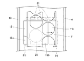
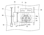
図1は、基板への接着テープ貼り付け装置の全体構造を示す一部省略平面図、図2は、図1のA−A方向の縦断正面図、図3は、図1におけるB−B方向の縦断側面図である。また、図4は、図3におけるC−C方向の矢視断面図である。図5は、テープ貼り付けテーブル部の概略平面図であり、図6は、図3のD−D方向の矢視断面図である。 1 is a partially omitted plan view showing the entire structure of the adhesive tape bonding apparatus to a substrate, FIG. 2 is a front elevational view in the direction of AA of FIG. 1, and FIG. 3 is the direction of BB in FIG. FIG. Moreover, FIG. 4 is arrow sectional drawing of the CC direction in FIG. FIG. 5 is a schematic plan view of the tape affixing table portion, and FIG. 6 is a cross-sectional view in the direction of arrows D in FIG.
図1乃至図3において、基板(ウエハ)への接着テープ貼り付け装置1は、基板供給/収納部aと、位置決め部bと、基板供給/収納部aのウエハWを一枚ずつ取り出して位置決め部bに搬送する基板搬送機構cと、上記位置決め部bで位置決めされたウエハWを受け取って保持する接着テープ貼り付け部dと、上記位置決め部b上のウエハWを接着テープ貼り付け部dに移送する基板搬送機構eと、上記接着テープ貼り付け部dに隣接して位置し、接着テープTをウエハWの外形に見合う大きさと形状に切断する接着テープ切断部fと、上記接着テープ貼り付け部dと接着テープ切断部fとの間を移動し、接着テープ切断部fで切断された接着テープTを吸着保持して接着テープ貼り付け部dに移送するとともに接着テープ貼り付け部dでウエハW上に接着テープTを貼り付ける接着テープ搬送機構gとからなり、これらを機台2上に設けて構成されている。
In FIG. 1 to FIG. 3, the adhesive
この発明で使用する基板の一実施形態として例えば半導体ウエハを用いた例を基に説明する。また、ウエハWに貼着する接着テープTは、ウエハWの裏面に貼り付けられるDAFを用い、上記ウエハWの外形よりも広幅でロール状に形成されたものを使用した例を基に説明する。なお、DAFの幅は、これに限定されるものではないが、例えばウエハWの外形の約2.5倍程度のものを用いる。 An embodiment using a semiconductor wafer, for example, will be described as an embodiment of the substrate used in the present invention. The adhesive tape T attached to the wafer W will be described based on an example using a DAF attached to the back surface of the wafer W and formed in a roll shape wider than the outer shape of the wafer W. . Although the width of the DAF is not limited to this, for example, a width of about 2.5 times the outer diameter of the wafer W is used.
図1のように上記基板供給/収納部aは、機台2上の右側角部分に位置し、図示しない適宜の昇降機構上に収納カセット3が載置されて構成されている。前記収納カセット3には、多数枚のウエハWが収納されている。
As shown in FIG. 1, the substrate supply / storage unit a is located at the right corner of the
前記位置決め部bは、基板供給/収納部aに近接して設けられている。基板搬送機構cは、先端でウエハWを吸着する吸着ハンドを有する搬送ロボット4を備え、該搬送ロボット4は、前後、上下及び旋回が可能になっている。前記搬送ロボット4は、前記基板供給/収納部aのウエハWを一枚ずつ取り出して位置決め部bに搬送するようになっている。 The positioning portion b is provided in proximity to the substrate supply / storage portion a. The substrate transfer mechanism c includes a transfer robot 4 having a suction hand that sucks the wafer W at its front end, and the transfer robot 4 can be turned back and forth, up and down, and swing. The transfer robot 4 takes out wafers W one by one in the substrate supply / storage unit a and transfers the wafers W to a positioning unit b.
前記搬送ロボット4は、ウエハWを上面から吸着して受け渡しを行うようになっている。なお、吸着ハンドには、非接触でウエハWを搬送する非接触ハンドを採用しても良い。 The transfer robot 4 sucks and delivers the wafer W from the top surface. A non-contact hand that transfers the wafer W non-contacting may be employed as the suction hand.
前記位置決め部bと接着テープ貼り付け部d及び接着テープ切断部fは、機台2上の中央部に一列に並べて設けられている。位置決め部bは、機台2上にウエハWを水平に保持するように設けられた位置決めテーブル5と、前記ウエハWを回転させる回転モータ6と、前記位置決めテーブル5上に保持されたウエハWのオリフラを光学的に検出する位置決めセンサ7が設けられている。
The positioning portion b, the adhesive tape affixing portion d and the adhesive tape cutting portion f are provided in line in the center of the
前記回転モータ6は、前記位置決めテーブル5に回転を付与するようになっており、該位置決めテーブル5にウエハWが載置されると、該位置決めテーブル5とウエハWを一体に回転させ、前記位置決めセンサ7でオリフラが検出される。該オリフラが検出されたウエハWは、該オリフラが所定の方向に向くように位置決めされる。なお、オリフラに代えてノッチが設けられたウエハWであっても同様に位置決めが行なわれる。
The rotary motor 6 applies rotation to the positioning table 5. When the wafer W is placed on the positioning table 5, the positioning table 5 and the wafer W are integrally rotated, and the positioning is performed. The orientation flat is detected by the
上記位置決め部b上に保持されたウエハWを接着テープ貼り付け部dに搬送する基板搬送機構eは、ウエハWの上面部分を吸着保持するとともに適宜な機構で昇降自在な吸着ハンド15を備える。該吸着ハンド15は、後端部分にスライダ16が設けられ、該スライダ16は、機台2上の位置決め部bと接着テープ貼り付け部dに沿って敷設されたレール16に摺動可能に嵌合されている。また、前記吸着ハンド15は、図示しない適宜な駆動源によりレール16に沿って、位置決め部bと接着テープ貼り付け部dとの間を移動するようになっている。前記吸着ハンド15に吸着されたウエハWは、位置決め部bから接着テープ貼り付け部dの保持テーブル9上に搬送されるようになっている。なお、吸着ハンド15に非接触でウエハWを保持する非接触ハンドを用いても良い。
The substrate transfer mechanism e for transferring the wafer W held on the positioning portion b to the adhesive tape affixing portion d has a
前記接着テープ切断部fは、前記接着テープ貼り付け部dを挟んだ位置決め部bと反対側に位置するように配置されている。前記接着テープ切断部fは、機台2上に間隔を開けて対向するように立設された一対の側板18、18間に配置され、両側板18、18間の中央付近に前記下部チャンバ8の上端部と略等しい高さ位置となる接着テープ切断テーブル19が水平に設けられている。この接着テープ切断テーブル19の下部位置に、接着テープ切断手段としてのカッター機構50が設けられている。該カッター機構50は、上下動と旋回動自在に配置され、接着テープ切断テーブル19に貼り付けられた接着テープTを開孔28の内周に沿って切り抜くようになっている。
The adhesive tape cutting portion f is disposed opposite to the positioning portion b across the adhesive tape affixing portion d. The adhesive tape cutting portion f is disposed between a pair of
図3のように両側板18、18間の一端側上部に接着テープ供給手段としての接着テープ供給ロール21が設けられている。また、両側板18、18の下部にはセパレータ巻取ロール22が設けられ、同じく両側板18、18の他端側の上部には切り抜き後の余剰接着テープを巻き取る接着テープ巻取ロール23が設けられている。また、両側板18、18間には、さらに接着テープ供給ロール21から引き出された接着テープTを下方に誘導するガイドローラ24と、前記ガイドローラ24の下方で接着テープTからセパレータTsを剥がす一対のガイドローラ25と、前記接着テープ切断テーブル19の上面に対して接着テープTの供給方向の後方に位置するガイドローラ26と、接着テープTを上方のテープ巻取ロール23に誘導する一対のガイドローラ27、27とが設けられている。そして、セパレータTsを剥がされた接着テープTは、一対のガイドローラ25、25とガイドローラ26の間の部分が、その粘着面を下に向けた略水平状態で、貼り付けテーブル19の上面に供給される。
Contact adhesive
前記接着テープ切断テーブル19は、図2乃至図5のようにウエハWの外形よりも大きな平面矩形状に形成され、その中央部にウエハWの外径と略等しい開孔28を備える。また、後述するが、前記開孔28の後端側(接着テープTの供給側)の両側には、接着テープTのウエハWへの貼り付け面と対向する部分に切欠き部19a、19bが設けられている。
The adhesive tape cutting table 19 is formed in a flat rectangular shape larger than the outer shape of the wafer W as shown in FIGS. 2 to 5, and is provided with an
前記接着テープ切断テーブル19には、前方側(接着テープTの回収側)の鉛直方向にスライダ38が設けられ、該スライダ38は、前方側に立設された支持枠36に沿って敷設されたレール37、37に摺動可能に嵌合している。前記接着テープ切断テーブル19は、図示しない適宜の駆動源により前記レール37、37に沿って昇降動可能になっている。
A
また、前記支持枠36の下端は、テーブル台39に固定されている。前記テーブル台39の下方で機枠2上には、接着テープTの幅方向に2本のレール40、40が敷設されている。前記テーブル台39の下面にはスライダ41、41が設けられ、前記スライダ41、41が前記レール40、40に摺動可能に嵌合している。また図6のように前記テーブル台39の前方側には前記レール40に沿って、ボールネジ43が並設され、このボールネジ43と螺合するナット部材44が前記テーブル台39に接続されている。また、前記ボールネジ43にはモータ42が接続され、該モータ42を駆動することで前記テーブル台39が前記接着テープ切断テーブル19と一体に接着テープTの幅方向に移動するようになっている。
Further, the lower end of the
前記テーブル台39は、図2、図3及び図6のようにその中央部に開孔39aが設けられている。また、前記開孔39aの前後側には、2枚の支持枠58、58が鉛直に設けられ、機枠2の開孔2aを貫通している。前記開孔2aは、前記テーブル台39の移動時に干渉しない大きさに形成されている。
As shown in FIGS. 2, 3 and 6, the
また、前記接着テープ切断テーブル19の上方位置で前記一対のガイドローラ25、25とガイドローラ26との間には押圧手段としての貼り付けローラ29と、前記接着テープTの下流側に位置するテープチャック機構30とが設けられている。前記貼り付けローラ29は、接着テープTの供給方向に沿った前後方向に図示しない適宜な駆動源により移動するようになっている。また、図4のように両側板18、18の内側に接着テープTの供給方向に沿ってレール45、45が敷設されている。また、前記テープチャック機構30の両側にはスライダ47、47が設けられ、前記スライダ47、47は、前記レール45、45に摺動可能に嵌合されている。前記テープチャック機構30は、図示しない適宜の駆動源により、前記レール45、45に沿って移動自在になっている。
Further, an
図3及び図4のように前記テープチャック機構30は、前記接着テープTを裏面側から押える上部チャック31と、該上部チャック31と対向して設けられ、前記接着テープTを上部チャック31とで挟持する剥離ローラ32と、前記上部チャック31を上下動させて接着テープTの挟持と解放を行うシリンダ33と、前記接着テープTを案内するガイドローラ35などで構成されている。
As shown in FIGS. 3 and 4, the
また、前記上部チャック31は、図4のように3分割されて構成されている。また、前記上部チャック31のそれぞれに対向して剥離ローラ32が3分割して設けられている。前記上部チャック31にはそれぞれシリンダ33が接続され、前記上部チャック31は、それぞれ独立にまたは同期して剥離ローラ32との間で接着テープTを挟持して引き出すようになっている。また、前記上部チャック31と剥離ローラ32は、図示しない適宜の機構で中央の上部チャック31M及び剥離ローラ32Mを基準に接着テープTの幅方向に移動可能になっており、接着テープTを挟持した際に幅方向の張力を調節可能になっている。
The
前記テープチャック機構30は、前記上部チャック31と剥離ローラ32とで接着テープTを挟持して、前記接着テープ切断テーブル19上に繰り出すようになっている。前記貼り付けローラ29は、シリンダ20によって上下動可能に構成され、図示しない適宜の駆動源によって往復移動することにより、接着テープTをテープ切断テーブル19上に押圧して接着させるようになっている。
The
また、剥離ローラ32も前記レール45に沿って前後に移動自在となるように架設され、適宜の駆動源によって往復移動することにより、カッター刃51による切り抜き後の接着テープ切断テーブル19上に接着された余剰接着テープTを接着テープ切断テーブル19の上面から剥がすようになっている。
Further, the peeling
図2及び図3のように前記カッター機構50は、前記開孔28と同軸心状に立設された回転軸52と、該回転軸52を回転させるモータ53と、前記回転軸52の上端に接続された支持板46と、該支持板46上に設けられたカッター刃51と、前記モータ53に接続された駆動プーリ54と、前記回転軸52の下端に軸止された従動プーリ55と、前記モータ53を支持するモータ枠57と、前記駆動プーリ54と従動プーリ55との間に張設されたベルト56と、前記テーブル台39から下垂された支持枠58と、該支持枠58の底板58a上に固定されたシリンダ59などを備えて構成されている。
As shown in FIGS. 2 and 3, the
前記モータ枠57は、前後方向に上方突出部57a、57aが立設され、前記上方突出部57a、57aのそれぞれの裏面にスライダ60、60が設けられている。また、前記支持枠58は、前記スライダ60を介して前記支持枠58上に敷設されたレール61に摺動可能に嵌合し、前記シリンダ59のシリンダ軸が伸縮することで前記カッター機構50が昇降動するようになっている。
In the
また、前記モータ53を駆動することで前記回転軸52が回転し、カッター刃51が前記回転軸52を中心に回転するようになっている。従って、前記カッター刃51は、シリンダ59の駆動により上昇すると接着テープ切断テーブル19上に接着された接着テープTの開孔28に位置する部分を突き破り、モータ53の起動による旋回で接着テープTを円形に切り抜くようになっている。前記開孔28はウエハWの外径と同径かそれよりも少し大径に形成され、前記カッター刃51はウエハWの外径とほぼ同等か、外径よりも少し小径に接着テープTを切り抜くように上昇位置での旋回半径を適宜の手段で調整可能に構成されている。
Further, by driving the motor 53, the rotating
なお、ウエハWにノッチやオリフラが形成されている場合は、接着テープTが図示しない適宜のカッター機構(例えば、V形状のカッターでの打ち抜きや直線カッター)により、カッター刃51による接着テープTの切り抜き前にノッチやオリフラの形状に切込みを形成しておけば良い。なお、本実施形態のようにウエハWにオリフラが形成されている場合、例えば貼り付けローラ29の支持枠に昇降可能にカッターを設けて、貼り付けローラ29の前進時にカッターを作用させて接着テープTに直線状の切込みを形成するようにしても良い。
When a notch or an orientation flat is formed in the wafer W, the adhesive tape T is not shown in the figure by a suitable cutter mechanism (for example, punching with a V-shaped cutter or linear cutter). Before cutting out, it is sufficient to form a notch in the shape of a notch or orientation flat. When an orientation flat is formed on the wafer W as in the present embodiment, for example, a cutter is provided so as to be able to move up and down on the support frame of the
前記接着テープ貼り付け部dは、前記位置決め部bと接着テープ切断部fの間に配置されている。前記接着テープ貼り付け部dは、後述する上部チャンバ70と合わさって真空チャンバを形成する下部チャンバ8を備える。該下部チャンバ8は、その内部に保持テーブル9が水平に設けられている。
The adhesive tape affixing portion d is disposed between the positioning portion b and the adhesive tape cutting portion f. The adhesive tape affixing portion d includes a
前記保持テーブル9は、下方にガイド部材12が固定され、該ガイド部材12は、下部チャンバ8の底部を介して前記保持テーブル9と平行に設けられた支持板14に支持されている。前記支持板14は、下部チャンバ8の下方のチャンバ枠に固定されたシリンダ13のシリンダ軸と接続され、該シリンダ13を作用させることで前記保持テーブル9は昇降するようになっている。
A guide member 12 is fixed to the lower side of the holding table 9, and the guide member 12 is supported by a support plate 14 provided parallel to the holding table 9 via the bottom of the
また、前記保持テーブル9は、その上面でウエハWを吸着保持するようウエハWの形状に多孔質体が設けられている。前記多孔質体の下方には、図示しない適宜のヒーターが設けられ、前記保持テーブル9を加熱するようになっている。また、該多孔質体には、前記下部チャンバ8の外側に連通した通気パイプ11が接続されており、該通気パイプ11には図示しない適宜の真空ポンプが接続されている(真空チャンバ内の減圧度と差圧が設けられるようになっている)。また、前記保持テーブル9のテーブル面と水平となるよう吸着パッド10が複数設けられている。該吸着パッド10は、前記支持板14の下面に固定されたシリンダ62のシリンダ軸と接続されており、前記吸着パッド10は、前記シリンダ62の作用で保持テーブル9の表面から突没自在になっている。なお、吸着パッド10に代えて吸着孔などウエハWを保持できるものであれば各種のものが使用できる。
Further, the holding table 9 is provided with a porous body in the shape of the wafer W so as to hold the wafer W by suction on its upper surface. Below the porous body, a suitable heater (not shown) is provided to heat the holding table 9. Further, the porous body is connected to a vent pipe 11 communicated with the outside of the
前記接着テープ貼り付け部dと接着テープ切断部fとの間の上方にはテープ搬送体70が設けられている。該テープ搬送体70の上方には前記側板18、18上から前記下部チャンバ8上方に至るまでの間に渡って支持板65が設けられ、該支持板65の下面にレール66、66が敷設されている。また前記レール66に沿ってボールネジ67が設けられている。該ボールネジ67の一端は、前記テープ貼り付け部dの上方で前記支持板65の一端に固定されたモータ枠87に軸支されており、前記ボールネジ67の他端は、機枠2の一端側の側板18に軸支されている。また、モータ枠87には、モータ68が固定され、該モータ68と前記ボールネジ67の一端が接続されている。
A
前記上部チャンバ70は、その上部に間隔を開けて支持枠71が設けられ、前記上部チャンバ70は、前記支持枠71に設けられたガイド部材73を介して支持されている。また、前記支持枠71にはシリンダ72が設けられ、該シリンダ72のシリンダ軸が前記上部チャンバ70に前記支持枠71を介して接続されている。また、前記支持枠71上にはスライダ74、74が設けられ、前記スライダ74、74は、前記レール66、66に摺動可能に嵌合している。また、前記ボールネジ67と螺合されたナット部材75は、前記支持枠71に固定されている。従って、前記モータ68を駆動することで、前記上部チャンバ70はレール66に沿って、接着テープ貼り付け部dと接着テープ切断部fの上方を移動するようになっている。
The
前記上部チャンバ70は、外側上部に真空アダプタ76が設けられ、図示しない適宜の真空ポンプに接続されている(なお、前記真空アダプタ76の真空源は、前記保持テーブル9の真空源とは別のラインで接続するか、バルブ等で前記真空チャンバ内の真空圧と前記保持テーブル9の真空圧に差圧を設けるようにしてある)。前記上部チャンバ70が下部チャンバ8と合わさって真空チャンバを形成した際に前記真空アダプタ76から排気することで真空チャンバ内を減圧状態とすることができる。また、前記真空アダプタ76から大気を導入することで真空チャンバ内の減圧を解除できるようになっている。なお、真空チャンバ内を減圧した後、アルゴンや窒素などの不活性ガスを導入することで、不活性ガス雰囲気下での貼り付けを行うことも可能である。
The
前記接着テープ搬送機構gは、前記上部チャンバ70と、その内部に形成された接着テープ搬送体77と、該接着テープ搬送体77を上部から支持する支持枠78と、前記支持枠78を上方から押圧し揺動させる押圧ローラ81と、前記真空チャンバ内でウエハWに接着テープTを貼り付けた後、さらに接着テープTをウエハWに押圧する貼り付けローラ83などを備えて構成されている。
The adhesive tape transport mechanism g includes the
前記接着テープ搬送体77は、ウエハWの外形とほぼ同径またはやや小径に形成された多孔質体で形成されている。また、前記接着テープ搬送体77には、真空パイプ88が接続され、該真空パイプ88は図示しない適宜の真空ポンプに接続されている。従って、前記真空ポンプにより前記接着テープ搬送体77に吸着力を発生させるようになっている(なお、前記真空チャンバ内の減圧度とは差圧が設けられるようになっている)。前記接着テープ搬送体77は、前記接着テープ切断テーブル19に形成された開孔28上で接着テープ切断テーブル19上に貼り付けられた接着テープTの裏面側を吸着保持するようになっている。
The adhesive
前記接着テープ搬送体77は、その上面の支持枠78に支持されている。該支持枠78の一端は、上チャンバ70内に下垂して設けられた支持枠86の下端の軸79に軸支され、揺動可能になっている。前記支持枠78の他端側は、上部チャンバ70内に下垂して設けられたバネ80及びガイド部材に接続され、前記支持枠78は、上部チャンバ70内に傾斜状態で吊架されている。また、上チャンバ70の内面上部には前記支持板78の上面に沿ってレール82が敷設されており、該レール82に沿って移動可能に押圧ローラ81が設けられている。該押圧ローラ81は、図示しない適宜の駆動源により、前記レール82に沿って移動することで前記支持板78をその上面から押圧し、該支持板78を前記テープ搬送体77と一体に水平方向に揺動させるようになっている。
The
また、前記上チャンバ70の側方には、支持板84が突出して設けられ、該支持板84の下方のローラ枠に貼り付けローラ83が軸支されている。該貼り付けローラ83は、前記支持板84に固定されたシリンダ85により昇降し、ウエハW上に貼り付けられた接着テープTを保持テーブル9上に押圧するようになっている。
Further, a support plate 84 is provided so as to project from the side of the
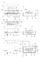
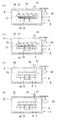
以上が、本発明の一実施形態に係る構成であり、次に本発明の接着テープ貼り付け装置1でのウエハWへの接着テープTの貼り付け動作について、図7乃至図11に基づいて以下に説明する。
The above is the configuration according to the embodiment of the present invention. Next, the operation of attaching the adhesive tape T to the wafer W in the adhesive
まず、接着テープTの貼り付けに先立って、基板供給/収納部aの収納カセット3から搬送ロボット4でウエハWを1枚ずつ取出して、位置決め部bの位置決めテーブル5上に移送する。続いて、位置決めテーブル5を回転させて位置決めセンサ7でウエハWのオリフラ位置を認識して位置決めする。なお、ウエハWは、表面に図示しない回路パターンが形成されており、その表面に図示しない保護テープが貼り付けられている。また、理解が容易なようにウエハWや接着テープの厚みは実際よりも誇張して描いている。また、図10及び図11は、接着テープTのウエハWへの貼り付け動作を概念的に示したもので、一部省略されている。
First, prior to bonding of the adhesive tape T, the wafer W is taken out one by one from the storage cassette 3 of the substrate supply / storage unit a by the transfer robot 4 and transferred onto the positioning table 5 of the positioning unit b. Subsequently, the positioning table 5 is rotated to recognize and position the orientation flat of the wafer W by the
また、上記位置決め動作と並行して、図10(a)のように接着テープ切断テーブル19上に接着テープTが前記テープチャック機構30に挟持されて引き出される。続いて、接着テープ切断テーブル19の開孔28上に接着テープTの左側寄りの部分が位置するように該接着テープ切断テーブル19を第1接着テープ切断位置P1に移動させておき、貼り付けローラ29で接着テープTを押圧して接着テープ切断テーブル19に貼り付ける。また、図示しない適宜のカッター機構でオリフラ部分の接着テープTを切断する。
Further, in parallel with the positioning operation, the adhesive tape T is held by the
図7(a)のように、位置決めされたウエハWは、吸着ハンド15の上面に吸着され、接着テープ貼り付け部dの保持テーブル9上へ搬送される。前記ウエハWは、保持テーブル9から突出した吸着パッド10上に吸着保持される。
As shown in FIG. 7A, the positioned wafer W is suctioned to the upper surface of the
また、上記保持テーブル9へのウエハWの移送と並行して上部チャンバ70が接着テープ切断部fの接着テープ切断テーブル19上へ移動し、前記開孔28上に下降する(図7(a)及び10(b)参照)。
Further, in parallel with the transfer of the wafer W to the holding table 9, the
前記保持テーブル9上に貼り付けられた接着テープTは、開孔28上で前記接着テープ搬送体77に裏面側から吸着される。その後、カッター刃51が上昇して開孔28に沿った一部に刃先が突き刺されて回転することで接着テープTがウエハWの形状にくり貫かれる。これにより、ウエハWの外形に沿ってくり貫かれた接着テープTは、前記テープ接着吸着体77に吸着保持された状態となる。また、接着テープ切断テーブル19上に貼り付けられた接着テープTには、くり貫き孔Thが形成される。
The adhesive tape T stuck on the holding table 9 is attracted to the
次に図7(b)のように吸着パッド10上に保持されたウエハWは、吸着パッド10の下降により保持テーブル9に吸着保持され、加熱される。また、上部チャンバ70は、接着テープ搬送体77にくり貫かれた接着テープTを吸着保持した状態で接着テープ切断テーブル19から上昇して離間する。前記上部チャンバ70の上昇に伴い、接着テープ搬送体77が押圧ローラ81の移動により水平状態から傾斜状態となる。また、カッター刃51が下降して接着テープTから離間する。
Next, as shown in FIG. 7B, the wafer W held on the
次に図7(c)及び図11(c)のように上部チャンバ70が、下部チャンバ8上に移動した後、下降して、真空チャンバが形成される。真空チャンバが形成されると、図示しない真空ポンプが作動して、真空チャンバ内が減圧され、真空状態となる。
Next, as shown in FIGS. 7 (c) and 11 (c), the
次に図8(d)のように保持テーブル9の吸着パッド10が上昇してウエハWが接着テープ搬送体77に吸着保持された接着テープTの傾斜下端に接着される。
Next, as shown in FIG. 8D, the
続いて図8(e)のように保持テーブル9がウエハWの下面位置まで上昇し、ウエハWを吸着保持しながら、保持テーブル9に内蔵された図示しない適宜のヒーターによりウエハWを加熱する。 Subsequently, as shown in FIG. 8E, the holding table 9 ascends to the lower surface position of the wafer W, and the wafer W is heated by a suitable heater (not shown) built in the holding table 9 while suction-holding the wafer W.
次に図8(f)のように上部チャンバ70の押圧ローラ81が図示矢印方向に移動することで、接着テープ搬送体77が傾動状態から水平状態へと揺動し、接着テープTが傾斜下端側からウエハW上に押圧貼り付けされる。
Next, as shown in FIG. 8F, the
次に図8(g)のように真空アダプタ76から大気を導入し、真空状態を解除することで接着テープTは、ウエハWへ押圧されさらに密着良く貼り付けられる。
Next, as shown in FIG. 8 (g), air is introduced from the
次に図9(h)のように上部チャンバ70が上昇して水平動し、貼り付けローラ83がウエハW上に臨み、続いて図9(i)のように貼り付けローラ83が上部チャンバ70の移動とともにウエハW上を転動することでウエハWへの接着テープTの貼り付けが完了する。なお、この貼付ローラ83による押圧は、例えば接着テープ搬送体77の外周からはみ出している場合や、真空チャンバ内での貼り付けが不十分な場合に有効であり、前記貼り付けローラ83を使用せずに貼り付けを行なっても良い。貼り付けが完了したウエハWは、保持テーブル9上から取り出され、搬送ロボット4により、収納カセット3に順次収納されていく。
Next, as shown in FIG. 9 (h), the
次に図5及び図11(d)のように接着テープ切断テーブル19が接着テープTの幅方向右側寄りの第2接着テープ切断位置P2に移動する。なお、接着テープ切断テーブル19の移動に先立って、テープチャック機構30が接着テープTの挟持を解放した状態で供給側へ移動することで剥離ローラ25が接着テープ切断テーブル19上を転動し、接着テープTが接着テープ切断テーブル19から剥離される。
Next, as shown in FIGS. 5 and 11 (d), the adhesive tape cutting table 19 is moved to the second adhesive tape cutting position P2 near the right side in the width direction of the adhesive tape T. Incidentally, prior to the movement of the adhesive tape cutting table 19, the peeling
前記接着テープ切断テーブル19が第2接着テープ切断位置P2に移動すると、テープチャック機構30が接着テープTの余剰部分を挟持して、接着テープTを所定の張力で接着テープ切断テーブル19上に引き出す。このとき、接着テープTの次のくり貫き部が接着テープ切断テーブル19の開孔28上に位置される。なお、この接着テープTのくり貫き部は、千鳥配置となるように設定されている。従って、接着テープTのくり貫き孔Thがほぼ円形である場合は、それぞれのくり貫き孔Thの間隔を近接することができ、接着テープTの消費量が低減できる。使用する接着テープの幅や貼り付ける基板の大きさにもよるが、通常千鳥配置の2列取りであれば4インチウエハであれば約10〜15%程度消費量を低減できる。
When the adhesive tape cutting table 19 moves to the second adhesive tape cutting position P2, the
上記動作が繰り返されることで、接着テープTのくり貫きが千鳥配置で行われながら、ウエハWに接着テープTが順次貼り付けられていく。 By repeating the above operation, the adhesive tape T is sequentially attached to the wafer W while the perforations of the adhesive tape T are performed in a staggered arrangement.
以上が、本発明の基板への接着テープの貼り付け装置の一実施形態であるが、発明の範囲内で適宜の変更が行なえる。 Although the above is one Embodiment of the bonding apparatus of the adhesive tape to the board | substrate of this invention, an appropriate change can be performed within the range of invention.
例えば、本発明は接着テープとして、DAFを貼り付ける例を基に説明したが、その他の各種の接着テープに適用できる。例えば、基板の表面を保護する保護テープや、基板に貼り付けるレジストフィルム、ダイシングテープなどにも適用できる。ダイシングテープに利用する場合は、基板の外周にリングフレームを有するものであっても良い。この場合は、接着テープ切断テーブルの開孔はリングフレームより内側に収まる形状に形成すれば良い。 For example, although the present invention was explained based on the example which sticks DAF as an adhesive tape, it is applicable to other various adhesive tapes. For example, the invention can be applied to a protective tape for protecting the surface of a substrate, a resist film to be attached to the substrate, a dicing tape, and the like. When using for a dicing tape, you may have a ring frame in the outer periphery of a board | substrate. In this case, the opening of the adhesive tape cutting table may be formed to fit inside the ring frame.
基板についても、半導体ウエハや各種の板状部材へ適用できる。また、基板の形状も円形だけでなく楕円などでも良く、千鳥配置で効率的に配置できる形状であれば、適宜の形状のものに適用できる。また、接着テープ搬送体の外形サイズあるいはカッターの切断位置を変えることで貼り付ける接着テープの大きさは適宜変更できる。また、本発明の実施形態においては接着テープから、2列でくり貫きを行なったが、2列以上であっても良い。また、基板への接着テープの貼り付け方法も上記に限定されず、接着テープを基板形状にくり貫き、これを搬送して貼り付けるものであれば各種の貼り付け方法を採用できる。 The substrate can also be applied to semiconductor wafers and various plate-like members. Also, the shape of the substrate may be not only circular but also elliptical, and any shape that can be efficiently arranged in a staggered arrangement can be applied to an appropriate shape. In addition, the size of the adhesive tape to be attached can be appropriately changed by changing the external size of the adhesive tape carrier or the cutting position of the cutter. In the embodiment of the present invention, the adhesive tape is perforated in two rows, but may be two or more. Further, the method of bonding the adhesive tape to the substrate is not limited to the above, and various bonding methods can be adopted as long as the adhesive tape is hollowed into the shape of the substrate and transported and attached.
また、本発明の実施形態では、先にくり貫いた接着テープを基板上に搬送して貼り付けるようにしたが、貼り付けテーブル上に載置された基板上に接着テープを供給するようにし、基板に接着テープを押圧して貼り付けた後に基板形状に接着テープをくり貫くようにしても良い。この場合、貼り付けテーブルに適宜の離型処理や、接着テープの保持力を保つ処理を施すことが好ましい。 Also, in the embodiment of the present invention, the previously cut adhesive tape is conveyed and attached onto the substrate, but the adhesive tape is supplied onto the substrate placed on the affixing table, After the adhesive tape is pressed and attached to the substrate, the adhesive tape may be cut into the shape of the substrate. In this case, it is preferable to apply an appropriate release treatment or a treatment for maintaining the holding power of the adhesive tape on the attachment table.
P1 第1接着テープ切断位置
P2 第2接着テープ切断位置
W 基板(ウエハ)
T 接着テープ
Th くり貫き孔
Ts セパレータ
a 基板供給/収納部
b 位置決め部
c 基板搬送機構
d 接着テープ貼り付け部
e 基板搬送機構
f 接着テープ切断部
g 接着テープ搬送機構
1 接着テープ貼り付け装置
2 機台
3 収納カセット
4 搬送ロボット
5 位置決めテーブル
6 回転モータ
7 位置決めセンサ
8 下部チャンバ
9 保持テーブル
10 吸着パッド
11 通気パイプ
12 ベルト
13 シリンダ
14 支持板
15 吸着ハンド
16 スライダ
17 レール
18 側板
18a 開口部
19 接着テープ切断テーブル
19a 切欠き部
19b 切欠き部
20 シリンダ
21 テープ供給ロール
22 セパレータ巻取ロール
23 テープ巻取ロール
24 ガイドローラ
25 剥離ローラ
26 ガイドローラ
27 ガイドローラ
28 開孔
29 貼り付けローラ
30 テープチャック機構
31 上部チャック
32 剥離ローラ
33 シリンダ
35 ガイドローラ
36 支持枠
37 レール
38 スライダ
39 テーブル台
40 カッター機構
41 スライダ
42 モータ
43 ボールネジ
44 ナット部材
45 レール
46 支持板
47 スライダ
50 カッター機構(接着テープ切断手段)
51 カッター刃
52 回転軸
53 モータ
54 駆動プーリ
55 従動プーリ
56 ベルト
57 モータ枠
57a 上方突出部
58 支持枠
58a 底板
59 シリンダ
60 スライダ
61 レール
62 シリンダ
65 支持板
66 レール
67 ボールネジ
68 モータ
70 上部チャンバ
71 支持枠
72 シリンダ
73 ガイド部材
74 スライダ
75 ナット部材
76 真空アダプタ
77 接着テープ搬送体
78 支持枠
79 軸
80 バネ
81 押圧ローラ
82 レール
83 貼り付けローラ
84 支持板
85 シリンダ
86 支持枠
87 モータ枠
P1 First adhesive tape cutting position P2 Second adhesive tape cutting position W Substrate (wafer)
T adhesive tape Th through hole Ts separator a substrate supply / storage part b positioning part c substrate transport mechanism d adhesive tape affixing part e substrate transport mechanism f adhesive tape cutting part g adhesive
78 Support frame
79 shaft 80
87 Motor frame
Claims (5)
前記接着テープ切断テーブルは、前記接着テープの幅方向の第1接着テープ切断位置と第2接着テープ切断位置との間が移動可能に構成され、
前記接着テープ搬送体は、前記第1接着テープ切断位置と第2接着テープ切断位置との上方と前記保持テーブル上との間を移動可能に構成され、
前記接着テープ切断テーブルを第1接着テープ切断位置と第2接着テープ切断位置との間を交互に移動させながら前記接着テープを切断することで、前記接着テープのくり貫き穴が千鳥配置となるように形成されることを特徴とする基板への接着テープ貼り付け装置。 A holding table on which a substrate is held, an adhesive tape cutting table provided with an opening having substantially the same shape as the substrate, and an adhesive tape for supplying an adhesive tape wider than the substrate on the adhesive tape cutting table A feeding means, a pressing means for pressing and sticking the adhesive tape supplied from the adhesive tape feeding means onto the adhesive tape cutting table, and provided below the opening of the adhesive tape cutting table along the opening Adhesive tape cutting means for cutting the adhesive tape, and an adhesive tape carrier provided so as to be movable between the adhesive tape cutting table and the holding table and having substantially the same shape as the substrate. After adhering the adhesive tape supplied from the adhesive tape supply means onto the adhesive tape cutting table, the adhesive tape is adhered from the back side The adhesive tape is held by suction by the tape carrier, and the adhesive tape is cut along the opening to hold the adhesive tape having substantially the same shape as the substrate on the adhesive tape carrier, and the adhesive tape is held on the holding table. In an adhesive tape affixing apparatus for conveying and pressing and sticking the adhesive tape onto a substrate,
The adhesive tape cutting table is configured to be movable between a first adhesive tape cutting position and a second adhesive tape cutting position in the width direction of the adhesive tape.
The adhesive tape transport body is configured to be movable between the upper side of the first adhesive tape cutting position and the second adhesive tape cutting position and the holding table.
By cutting the adhesive tape while alternately moving the adhesive tape cutting table between the first adhesive tape cutting position and the second adhesive tape cutting position, the holes of the adhesive tape are arranged in a zigzag manner. An adhesive tape adhering apparatus to a substrate, characterized in that it is formed into
前記貼り付けテーブルを前記接着テープと相対的に水平動可能に設け、前記接着テープを基板の外形に沿って切断する毎に前記貼り付けテーブルを前記接着テープと相対的に水平動させて、前記接着テープのくり貫き穴が千鳥配置となるように形成されることを特徴とする基板への接着テープ貼り付け装置。 Affixing table on which the substrate is held, adhesive tape supply means for supplying adhesive tape wider than the substrate on the affixing table, adhesive table supplied from the adhesive tape supply means An adhesive tape affixing apparatus to a substrate comprising: pressing means for pressing and sticking to an upper substrate; and adhesive tape cutting means for cutting the adhesive tape along the outer shape of the substrate,
The affixing table is provided so as to be horizontally movable relative to the adhesive tape, and the affixing table is horizontally moved relative to the adhesive tape each time the adhesive tape is cut along the outer shape of the substrate. An adhesive tape adhering apparatus to a substrate, wherein holes of the adhesive tape are formed in a staggered arrangement.
前記接着テープ切断テーブルを接着テープの幅方向に移動可能に構成しておき、前記接着テープを切断してくり貫く毎に接着テープの供給と前記接着テープ切断テーブルの移動を行うことで、前記接着テープを千鳥配置でくり貫いていくようにしたことを特徴とする基板への接着テープの貼り付け方法。 An adhesive tape wider than the substrate is pasted on an adhesive tape cutting table provided with an opening having substantially the same shape as the substrate, and while holding the adhesive tape by suction from the back side of the adhesive tape on the opening. The adhesive tape is cut along the opening to hold the adhesive tape perforated in the adhesive tape carrier, the adhesive tape is transported onto the substrate, and the adhesive tape is pressed onto the substrate. In the adhesive tape sticking method to the substrate to be stuck,
The bonding tape cutting table is configured to be movable in the width direction of the bonding tape, and the bonding is performed by supplying the bonding tape and moving the bonding tape cutting table each time the bonding tape is cut and cut. A method of applying an adhesive tape to a substrate, characterized in that the tapes are cut through in a staggered arrangement.
前記貼り付けテーブルと前記接着テープとを相対的に水平動可能に設け、前記接着テープを基板の外形に沿って切断してくり貫く毎に前記貼り付けテーブルと前記接着テープとを相対的に水平動させて、前記接着テープのくり貫き孔が千鳥配置となるように形成されることを特徴とする基板への接着テープ貼り付け方法。 A substrate is held on a pasting table, an adhesive tape wider than the substrate is supplied onto the pasting table, and the supplied adhesive tape is pressed against the substrate on the pasting table and pasted. In the adhesive tape adhering method to a substrate, the adhesive tape is cut along the outer shape of the substrate.
The pasting table and the adhesive tape are provided so as to be relatively movable horizontally, and the pasting table and the adhesive tape are relatively horizontal each time the adhesive tape is cut and cut along the outer shape of the substrate. A method of attaching an adhesive tape to a substrate, characterized in that the perforations of the adhesive tape are formed in a staggered arrangement by moving the adhesive tape.
Priority Applications (1)
| Application Number | Priority Date | Filing Date | Title |
|---|---|---|---|
| JP2015061216A JP6500170B2 (en) | 2015-03-24 | 2015-03-24 | Adhesive tape bonding apparatus to substrate and method of bonding |
Applications Claiming Priority (1)
| Application Number | Priority Date | Filing Date | Title |
|---|---|---|---|
| JP2015061216A JP6500170B2 (en) | 2015-03-24 | 2015-03-24 | Adhesive tape bonding apparatus to substrate and method of bonding |
Publications (3)
| Publication Number | Publication Date |
|---|---|
| JP2016181613A JP2016181613A (en) | 2016-10-13 |
| JP2016181613A5 JP2016181613A5 (en) | 2018-06-14 |
| JP6500170B2 true JP6500170B2 (en) | 2019-04-17 |
Family
ID=57132733
Family Applications (1)
| Application Number | Title | Priority Date | Filing Date |
|---|---|---|---|
| JP2015061216A Active JP6500170B2 (en) | 2015-03-24 | 2015-03-24 | Adhesive tape bonding apparatus to substrate and method of bonding |
Country Status (1)
| Country | Link |
|---|---|
| JP (1) | JP6500170B2 (en) |
Families Citing this family (3)
| Publication number | Priority date | Publication date | Assignee | Title |
|---|---|---|---|---|
| EP3598480B1 (en) * | 2018-07-18 | 2020-09-23 | Infineon Technologies AG | Device and method for debonding a structure from a main surface region of a carrier |
| CN110299549B (en) * | 2019-07-10 | 2023-06-27 | 苏州巨一智能装备有限公司 | High-precision assembling device and method for membrane electrode assembly |
| WO2023017700A1 (en) * | 2021-08-11 | 2023-02-16 | 東京応化工業株式会社 | Bonding apparatus and bonding method |
Family Cites Families (6)
| Publication number | Priority date | Publication date | Assignee | Title |
|---|---|---|---|---|
| JP2732739B2 (en) * | 1992-01-13 | 1998-03-30 | 日立造船株式会社 | Manufacturing method of conductive foil |
| JP2966409B1 (en) * | 1998-10-08 | 1999-10-25 | グンゼ株式会社 | Sheet material cutting device |
| JP3607143B2 (en) * | 1999-11-19 | 2005-01-05 | 株式会社タカトリ | Method and apparatus for attaching protective tape to semiconductor wafer |
| JP2001269899A (en) * | 2000-03-24 | 2001-10-02 | Gunze Ltd | Cutting method and cutting device for sheet material |
| JP4530638B2 (en) * | 2003-10-07 | 2010-08-25 | 日東電工株式会社 | Method and apparatus for applying protective tape to semiconductor wafer |
| JP5942121B2 (en) * | 2012-03-06 | 2016-06-29 | 群馬県 | Rotary die cutter system |
-
2015
- 2015-03-24 JP JP2015061216A patent/JP6500170B2/en active Active
Also Published As
| Publication number | Publication date |
|---|---|
| JP2016181613A (en) | 2016-10-13 |
Similar Documents
| Publication | Publication Date | Title |
|---|---|---|
| JP5543813B2 (en) | Work transfer method and work transfer device | |
| JP5543812B2 (en) | Adhesive tape application method and adhesive tape application device | |
| JP4612453B2 (en) | Method and apparatus for applying tape to wafer | |
| JP5273791B2 (en) | Equipment for applying adhesive tape to substrates | |
| JP4906518B2 (en) | Adhesive tape attaching method and adhesive tape attaching apparatus using the same | |
| JP2008147249A (en) | Substrate adhering method and apparatus using same method | |
| TW201112319A (en) | Adhesive tape joining method and adhesive tape joining apparatus | |
| JP4941944B2 (en) | Method and apparatus for attaching adhesive tape to substrate | |
| JP5750632B2 (en) | Sheet sticking device to substrate | |
| JP6500170B2 (en) | Adhesive tape bonding apparatus to substrate and method of bonding | |
| JP2005159044A (en) | Method for adhering adhesive tape to ring frame, its device and substrate mounter to the ring frame | |
| JP2012216606A (en) | Substrate transfer method and substrate transfer device | |
| JP6621365B2 (en) | How to peel off the protective tape | |
| KR20180000429A (en) | A vacuum laminator for bonding adhesive film to carrier wafer and a method for operating the same | |
| JP2009246067A5 (en) | ||
| JP2010165962A (en) | Support table of wafer | |
| KR20160046732A (en) | Method and apparatus for joining adhesive tape | |
| JP2009253083A (en) | Sheet sticking device and sticking method | |
| JP2021136257A (en) | Sheet peeling method and sheet peeling device | |
| JP2010062270A5 (en) | ||
| KR100819791B1 (en) | An apparatus and method for attatching tape for manufacturing of semiconductor package | |
| JP7109244B2 (en) | Adhesive Tape Conveying Method and Adhesive Tape Conveying Device | |
| JP5373008B2 (en) | Substrate bonding method | |
| JP2005276987A (en) | Ultra-thin chip manufacturing process and manufacturing apparatus therefor | |
| JP6818576B2 (en) | Sheet pasting device and pasting method |
Legal Events
| Date | Code | Title | Description |
|---|---|---|---|
| A621 | Written request for application examination |
Free format text: JAPANESE INTERMEDIATE CODE: A621 Effective date: 20180312 |
|
| A521 | Request for written amendment filed |
Free format text: JAPANESE INTERMEDIATE CODE: A523 Effective date: 20180405 |
|
| A977 | Report on retrieval |
Free format text: JAPANESE INTERMEDIATE CODE: A971007 Effective date: 20181122 |
|
| TRDD | Decision of grant or rejection written | ||
| A01 | Written decision to grant a patent or to grant a registration (utility model) |
Free format text: JAPANESE INTERMEDIATE CODE: A01 Effective date: 20181203 |
|
| A61 | First payment of annual fees (during grant procedure) |
Free format text: JAPANESE INTERMEDIATE CODE: A61 Effective date: 20181210 |
|
| R150 | Certificate of patent or registration of utility model |
Ref document number: 6500170 Country of ref document: JP Free format text: JAPANESE INTERMEDIATE CODE: R150 |
|
| R250 | Receipt of annual fees |
Free format text: JAPANESE INTERMEDIATE CODE: R250 |