JP6494930B2 - Game machine - Google Patents

Game machine Download PDF

Info

Publication number
JP6494930B2
JP6494930B2 JP2014129321A JP2014129321A JP6494930B2 JP 6494930 B2 JP6494930 B2 JP 6494930B2 JP 2014129321 A JP2014129321 A JP 2014129321A JP 2014129321 A JP2014129321 A JP 2014129321A JP 6494930 B2 JP6494930 B2 JP 6494930B2
Authority
JP
Japan
Prior art keywords
hold
change
hold display
display
notice
Prior art date
Legal status (The legal status is an assumption and is not a legal conclusion. Google has not performed a legal analysis and makes no representation as to the accuracy of the status listed.)
Active
Application number
JP2014129321A
Other languages
Japanese (ja)
Other versions
JP2016007332A (en
JP2016007332A5 (en
Inventor
智一 三品
智一 三品
Original Assignee
株式会社藤商事
Priority date (The priority date is an assumption and is not a legal conclusion. Google has not performed a legal analysis and makes no representation as to the accuracy of the date listed.)
Filing date
Publication date
Application filed by 株式会社藤商事 filed Critical 株式会社藤商事
Priority to JP2014129321A priority Critical patent/JP6494930B2/en
Publication of JP2016007332A publication Critical patent/JP2016007332A/en
Publication of JP2016007332A5 publication Critical patent/JP2016007332A5/ja
Application granted granted Critical
Publication of JP6494930B2 publication Critical patent/JP6494930B2/en
Active legal-status Critical Current
Anticipated expiration legal-status Critical

Links

Images

Description

この発明は、保留変化予告および特定表示予告を実行可能な遊技機に関する。 This invention relates to pending change notice and specific display notice capable of executing the gaming machine.

近年、パチンコ機等の遊技機において、始動記憶の情報を識別情報の変動動作の開始前に先読み判定しておき、その始動情報に対応する変動動作が開始される前の数ゲーム前から所定の先読み演出を実行させる先読み予告機能を備えたものが提案されている。この先読み予告の一態様として、先読み予告の対象の始動情報に対応する保留表示の保留表示態様を、通常と異なる特別態様(たとえば白色から赤色)で表示する先読み保留変化予告が知られている。保留されている変動動作が順次消化されることに伴い、保留表示の表示位置がシフトされてかつ表示個数も減らされるが、この間も特別態様の保留表示は、表示位置を変えながら連続的に表示され続ける。   In recent years, in a gaming machine such as a pachinko machine, the information stored in the start memory is pre-read before the start of the change operation of the identification information, and a predetermined number of games before the start of the change operation corresponding to the start information are determined in advance. A device having a pre-reading notice function for executing a pre-reading effect has been proposed. As one aspect of this pre-reading notice, a pre-reading hold change notice that displays the hold display form of the hold display corresponding to the start information subject to the prefetch notice in a special form (for example, white to red) different from normal is known. As the fluctuating movements that have been put on hold are digested in sequence, the display position of the hold display is shifted and the number of displays is reduced. During this time, the hold display in a special mode is displayed continuously while changing the display position. Continue to be.

特許4841588号公報Japanese Patent No. 4841588

保留変化予告(先読み保留変化予告)だけでなく、併せて特定表示予告を行うことも提案されている。 In addition to the hold change notice ( prefetch hold change notice ), it has also been proposed to perform a specific display notice together.

この発明は、特定表示予告の演出効果の向上を図ることができる、遊技機を提供することを目的とする。 An object of the present invention is to provide a gaming machine capable of improving the effect of the specific display notice .

前記の目的を達成するための請求項1に記載の発明は、所定の条件の成立に基づいて、始動情報を取得する始動情報取得手段(40A)と、所定の上限数を限度に、前記始動情報を保留記憶として記憶する保留記憶手段(61,62)と、前記保留記憶手段に記憶された前記始動情報に基づき、遊技者にとって有利な特定遊技状態とするか否かの抽選を行う抽選手段(40A)と、所定の開始条件が成立したことに基づいて、識別情報の可変表示を開始する識別情報表示手段(35,36)と、前記開始条件の成立に先立って、前記始動情報を判定する先読み判定手段と、前記保留記憶手段に記憶された前記始動情報に基づく保留表示(102)を表示可能な保留表示手段(101)と、前記先読み判定手段による判定結果に基づいて、前記開始条件の成立前に前記保留表示を、通常保留表示態様または該通常保留表示態様とは異なる特別保留表示態様で表示することにより、前記特定遊技状態となる可能性を予告する保留変化予告を実行する保留変化予告制御手段(41A)と、遊技者が操作可能な操作手段(13)と、前記先読み判定手段による判定結果に基づいて、前記開始条件の成立前に前記保留表示を、前記通常保留表示態様および前記特別保留表示態様とは異なる、前記操作手段による操作を受け付け可能とする所定の操作保留表示態様で表示する操作保留変化予告を実行可能な操作保留変化予告制御手段(41A)と、前記識別情報表示手段により前記識別情報の可変表示が開始される場合に、該可変表示に対応する前記保留表示を特定表示(104)として所定領域に表示可能な特定表示手段(103)と、前記抽選手段および/または前記先読み判定手段による判定結果に基づいて、前記特定表示を、通常表示態様または該通常表示態様とは異なる複数種類の特別表示態様のうちいずれかの特別表示態様で表示することにより、前記特定遊技状態となる可能性を予告する特定表示予告を実行する特定表示予告制御手段(41A)とを備えた遊技機(201)であって、前記特定表示予告制御手段は、前記抽選手段による抽選の結果が、特定遊技状態とすることに当選した場合と、該特定遊技状態とすることに落選した場合とのいずれであっても、前記特定表示を第1特別表示態様で表示することが可能であり 、さらに、前記抽選手段による抽選の結果が、特定遊技状態とすることに当選した場合にのみ、前記特定表示を該第1特別表示態様とは異なる第2特別表示態様で表示することが可能であり、前記特定表示予告制御手段は、前記特定表示予告の対象となっている前記始動情報に対応する変動パターンが、少なくとも第1リーチ演出と該第1リーチ演出の終了後に実行される第2リーチ演出からなるリーチ変動パターンにおいて、前記特定表示予告を前記第1リーチ演出中と前記第2リーチ演出中とにおいて実行可能であり、前記特別表示予告制御手段により、前記可変表示を開始したときの前記特定表示が前記複数種類の特別表示態様のうち特定の特別表示態様で表示され、その後、前記リーチ変動パターンにおいて前記特定表示予告が1回実行されて前記特定表示が前記第2特別表示態様で表示される場合、前記リーチ変動パターンにおいて前記特定表示予告が前記第1リーチ演出中に実行され前記第2特別表示態様で表示されるよりも、前記リーチ変動パターンにおいて前記特定表示予告が前記第1リーチ演出には実行されず前記第2リーチ演出中に実行され前記第2特別表示態様で表示されやすく構成されていることを特徴とする、遊技機を提供する。
なお、括弧内の英数字は、後述の実施形態における対応構成要素の参照符号を表すものであるが、これらの参照符号により特許請求の範囲を実施形態に限定する趣旨ではない。
In order to achieve the above object, the invention according to claim 1 is characterized in that start information acquisition means (40A) for acquiring start information on the basis of establishment of a predetermined condition and the start up to a predetermined upper limit number. On-hold storage means (61, 62) for storing information as on-hold storage, and lottery means for performing lottery on whether or not to enter a specific gaming state advantageous to the player based on the start-up information stored in the on-hold storage means (40A) and identification information display means (35, 36) for starting variable display of identification information based on the establishment of a predetermined start condition, and determining the start information prior to establishment of the start condition Based on the determination result by the prefetch determination means, the hold display means (101) capable of displaying the hold display (102) based on the start information stored in the hold storage means, and the prefetch determination means Said hold display before establishment of start conditions, by displaying in the normal hold display mode or the normal hold display mode and that is different from special hold display state like, pending changes that notice may become the specific gaming state Based on the determination result by the hold change notice control means (41A) for executing the notice, the operation means (13) that can be operated by the player, and the prefetch determination means, the hold indication is displayed before the start condition is established, Different from the normal hold display mode and the special hold display mode, an operation hold change notice control unit (41A) capable of executing an operation hold change notice displayed in a predetermined operation hold display mode in which an operation by the operation unit can be accepted. ), And when the variable display of the identification information is started by the identification information display means, the hold display corresponding to the variable display is set as a specific display (104). Specific display means (103) that can be displayed on the screen, and based on the determination result by the lottery means and / or the prefetch determination means, the specific display is a normal display mode or a plurality of types of special display different from the normal display mode. A gaming machine (201) provided with specific display advance notice control means (41A) for executing a specific display advance notice for predicting the possibility of entering the specific gaming state by displaying in any of the special display forms. The specific display notice control means may be either the case where the result of the lottery by the lottery means is won for the specific gaming state or the case where the lottery is lost for the specific gaming state. The specific display can be displayed in the first special display mode, and only when the result of the lottery by the lottery means that the player is elected to enter the specific gaming state. The specific display can be displayed in a second special display mode different from the first special display mode, and the specific display notice control means corresponds to the start information that is the target of the specific display notice. In the reach variation pattern including at least a first reach effect and a second reach effect that is executed after the first reach effect is finished, the specific display notice is displayed during the first reach effect and the second reach effect. be feasible in the mid Prefecture, by the special display notice control unit, the specific display at the start of the variable display is displayed in a particular Japanese Schedule示態like among the plurality of types of Japanese Schedule示態like, then, when the specific display notice before Symbol reach varying pattern said specific display is performed once is displayed in the second special display form, on the reach varying pattern In this case, the specific display notice is not executed during the first reach effect in the reach variation pattern than when the specific display notice is executed during the first reach effect and displayed in the second special display mode. Provided is a gaming machine that is configured to be easily displayed in the second special display mode that is executed during the second reach production.
In addition, although the alphanumeric characters in parentheses represent reference numerals of corresponding components in the embodiments described later, the scope of the claims is not limited to the embodiments by these reference numerals.

本発明によれば、特定表示予告の演出効果の向上を図ることができる遊技機を提供できる。 ADVANTAGE OF THE INVENTION According to this invention, the gaming machine which can aim at the improvement effect of the specific display notice can be provided.

本発明の第1実施形態に係る遊技機が適用されたパチンコ機の斜視図である。1 is a perspective view of a pachinko machine to which a gaming machine according to a first embodiment of the present invention is applied. 図1に示すパチンコ機の遊技盤の概略正面図である。It is a schematic front view of the game board of the pachinko machine shown in FIG. 液晶表示ユニットの表示内容の一例を示す図である。It is a figure which shows an example of the display content of a liquid crystal display unit. 液晶表示ユニットの表示内容の一例を示す図である。It is a figure which shows an example of the display content of a liquid crystal display unit. パチンコ機の電気的構成を示すブロック図である。It is a block diagram which shows the electric constitution of a pachinko machine. 主制御基板の電気的構成を示すブロック図である。It is a block diagram which shows the electric constitution of a main control board. 演出制御基板の電気的構成を示すブロック図である。It is a block diagram showing an electrical configuration of the effect control board. 第1および第2の保留メモリの構成を説明する図である。It is a figure explaining the structure of the 1st and 2nd reservation memory. 演出制御基板に送信される変動パターンコマンドを説明する図である。It is a figure explaining the variation pattern command transmitted to an effect control board. 演出制御基板に送信される保留加算コマンドを説明する図である。It is a figure explaining the pending | holding addition command transmitted to an effect control board. 演出制御基板に送信される保留加算コマンドを説明する図である。It is a figure explaining the pending | holding addition command transmitted to an effect control board. 先読み保留変化予告用の抽選表の一例を示す図である。It is a figure which shows an example of the lottery table for prefetch hold change notice. 先読み保留変化予告用の抽選表の一例を示す図である。It is a figure which shows an example of the lottery table for prefetch hold change notice. 当該変動保留表示の保留表示態様が「白」である場合における、当該変動保留変化予告用の抽選表の一例を示す図である。It is a figure which shows an example of the lottery table | surface for the said change hold change notice when the hold display mode of the said change hold display is "white". 当該変動保留表示の保留表示態様が「白」である場合における、当該変動保留変化予告用の抽選表の一例を示す図である。It is a figure which shows an example of the lottery table | surface for the said change hold change notice when the hold display mode of the said change hold display is "white". 当該変動保留表示の保留表示態様が「白点滅」である場合における、当該変動保留変化予告用の抽選表の一例を示す図である。It is a figure which shows an example of the lottery table | surface for the said change hold change notice when the change display mode of the change hold display is "white blinking". 当該変動保留表示の保留表示態様が「白点滅」である場合における、当該変動保留変化予告用の抽選表の一例を示す図である。It is a figure which shows an example of the lottery table | surface for the said change hold change notice when the change display mode of the change hold display is "white blinking". 当該変動保留表示の保留表示態様が「青」である場合における、当該変動保留変化予告用の抽選表の一例を示す図である。It is a figure which shows an example of the lottery table | surface for the said variable hold change notice when the hold display mode of the said variable hold display is "blue". 当該変動保留表示の保留表示態様が「青」である場合における、当該変動保留変化予告用の抽選表の一例を示す図である。It is a figure which shows an example of the lottery table | surface for the said variable hold change notice when the hold display mode of the said variable hold display is "blue". 当該変動保留表示の保留表示態様が「緑」である場合における、当該変動保留変化予告用の抽選表の一例を示す図である。It is a figure which shows an example of the lottery table for the said variable hold change notice when the hold display mode of the said variable hold display is "green". 当該変動保留表示の保留表示態様が「緑」である場合における、当該変動保留変化予告用の抽選表の一例を示す図である。It is a figure which shows an example of the lottery table for the said variable hold change notice when the hold display mode of the said variable hold display is "green". 当該変動保留表示の保留表示態様が「赤」である場合における、当該変動保留変化予告用の抽選表の一例を示す図である。It is a figure which shows an example of the lottery table | surface for the said change hold change notice in case the hold display mode of the said change hold display is "red". 当該変動保留表示の保留表示態様が「デンジャー」である場合における、当該変動保留変化予告用の抽選表の一例を示す図である。It is a figure which shows an example of the lottery table | surface for the said change hold change notice in case the hold display mode of the said change hold display is "Danger". 主制御基板におけるタイマ割込処理の流れを示すフローチャートである。It is a flowchart which shows the flow of the timer interruption process in a main control board. 図19に示す第1(第2)特別図柄管理処理の流れを示すフローチャートである。It is a flowchart which shows the flow of the 1st (2nd) special symbol management process shown in FIG. 図20に示す第1(第2)特別図柄始動口チェック処理の流れを示すフローチャートである。It is a flowchart which shows the flow of the 1st (2nd) special symbol starting port check process shown in FIG. 図19に示す特別電動役物管理処理の流れを示すフローチャートである。It is a flowchart which shows the flow of the special electric accessory management process shown in FIG. 液晶表示ユニットの表示内容の一例を示す図である。It is a figure which shows an example of the display content of a liquid crystal display unit. 液晶表示ユニットの表示内容の一例を示す図である。It is a figure which shows an example of the display content of a liquid crystal display unit. 液晶表示ユニットの表示内容の一例を示す図である。It is a figure which shows an example of the display content of a liquid crystal display unit. 液晶表示ユニットの表示内容の一例を示す図である。It is a figure which shows an example of the display content of a liquid crystal display unit. 保留加算コマンドの受信時における演出制御基板の処理の流れを示すフローチャートである。It is a flowchart which shows the flow of a process of the production | presentation control board at the time of reception of a pending | holding addition command. 図27に示す先読み保留変化予告抽選処理の内容を示すフローチャートである。It is a flowchart which shows the content of the prefetch hold change notice lottery process shown in FIG. 図27に示す先読みカード予告抽選処理の内容を示すフローチャートである。It is a flowchart which shows the content of the prefetch card notice lottery process shown in FIG. 変動パターンコマンドの受信時における演出制御基板の処理の流れを示すフローチャートである。It is a flowchart which shows the flow of a process of the production | presentation control board at the time of reception of a fluctuation pattern command. 図30に示す当該変動保留変化予告抽選処理の流れを示すフローチャートである。It is a flowchart which shows the flow of the said change hold | maintenance change notice lottery process shown in FIG. 図30に示すカード予告抽選処理の流れを示すフローチャートである。It is a flowchart which shows the flow of the card notice lottery process shown in FIG. カード予告時における、液晶表示ユニットの表示内容の一例を示す図である。It is a figure which shows an example of the display content of a liquid crystal display unit at the time of card notice. 本発明の第1実施形態の第1の変形例の抽選表の一例を示す図である。It is a figure which shows an example of the lottery table | surface of the 1st modification of 1st Embodiment of this invention. 本発明の第1実施形態の第2の変形例の抽選表の一例を示す図である。It is a figure which shows an example of the lottery table | surface of the 2nd modification of 1st Embodiment of this invention. 本発明の第2実施形態に係る演出制御基板の電気的構成を示すブロック図である。It is a block diagram which shows the electrical structure of the presentation control board which concerns on 2nd Embodiment of this invention. 本発明の第2実施形態に係る、先読み保留変化予告の保留態様変化パターンの一例を示す図である。It is a figure which shows an example of the pending | holding mode change pattern of the prefetch hold change notice based on 2nd Embodiment of this invention. 本発明の第2実施形態に係る、液晶表示ユニットの表示内容の一例を示す図である(その1)。It is a figure which shows an example of the display content of the liquid crystal display unit based on 2nd Embodiment of this invention (the 1). 本発明の第2実施形態に係る、液晶表示ユニットの表示内容の一例を示す図である(その2)。It is a figure which shows an example of the display content of the liquid crystal display unit based on 2nd Embodiment of this invention (the 2). 本発明の第2実施形態に係る、液晶表示ユニットの表示内容の一例を示す図である(その3)。It is a figure which shows an example of the display content of the liquid crystal display unit based on 2nd Embodiment of this invention (the 3). 本発明の第2実施形態に係る、保留加算コマンドの受信時における演出制御基板の処理の流れを示すフローチャートである。It is a flowchart which shows the flow of a process of the presentation control board at the time of reception of the pending | holding addition command based on 2nd Embodiment of this invention. 図41に示す保留表示更新処理の内容を示すフローチャートである。It is a flowchart which shows the content of the pending | holding display update process shown in FIG. 本発明の第2実施形態に係る、ボタン保留表示演出中における処理の流れを示すフローチャートである。It is a flowchart which shows the flow of the process in the button hold display effect based on 2nd Embodiment of this invention. 本発明の第2実施形態に係る、変動パターンコマンドの受信時における演出制御基板の処理の流れを示すフローチャートである。It is a flowchart which shows the flow of a process of the presentation control board at the time of reception of the fluctuation pattern command based on 2nd Embodiment of this invention. 図44に示す当該変動保留表示更新処理の内容を示すフローチャートである。It is a flowchart which shows the content of the said change hold display update process shown in FIG. 本発明の第2実施形態に係る、ランクアップ演出時における処理の流れを示すフローチャートである。It is a flowchart which shows the flow of the process at the time of a rank improvement effect based on 2nd Embodiment of this invention. 先読み保留変化予告から当該変動保留変化予告へのシフト移行時における、液晶表示ユニットの表示内容の一例を示す図である。It is a figure which shows an example of the display content of a liquid crystal display unit at the time of the shift transfer from the prefetch hold change notice to the said change hold change notice. 本発明の第2実施形態に係るボタン保留表示演出中における、液晶表示ユニットの表示内容の一例を示す図である(その1)。It is a figure which shows an example of the display content of a liquid crystal display unit in the button holding | maintenance display effect which concerns on 2nd Embodiment of this invention (the 1). 本発明の第2実施形態に係るボタン保留表示演出中における、液晶表示ユニットの表示内容の一例を示す図である(その2)。It is a figure which shows an example of the display content of a liquid crystal display unit in the button holding | maintenance display effect which concerns on 2nd Embodiment of this invention (the 2). 本発明の第2実施形態の第1の変形例に係る、当該変動保留表示更新処理の内容を示すフローチャートである。It is a flowchart which shows the content of the said change pending | holding display update process based on the 1st modification of 2nd Embodiment of this invention. 本発明の第2実施形態の第1の変形例に係るボタン保留表示演出中における、液晶表示ユニットの表示内容の一例を示す図である(その1)。It is a figure which shows an example of the display content of a liquid crystal display unit in the button holding | maintenance display effect which concerns on the 1st modification of 2nd Embodiment of this invention (the 1). 本発明の第2実施形態の第1の変形例に係るボタン保留表示演出中における、液晶表示ユニットの表示内容の一例を示す図である(その2)。It is a figure which shows an example of the display content of a liquid crystal display unit in the button suspension display effect which concerns on the 1st modification of 2nd Embodiment of this invention (the 2). 本発明の第2実施形態の第2の変形例に係る、当該変動保留表示更新処理の内容を示すフローチャートである。It is a flowchart which shows the content of the said change pending | holding display update process based on the 2nd modification of 2nd Embodiment of this invention. 本発明の第2実施形態の第2の変形例に係る、ランクアップ演出時における処理の流れを示すフローチャートである。It is a flowchart which shows the flow of the process at the time of a rank improvement effect based on the 2nd modification of 2nd Embodiment of this invention. 本発明の第2実施形態の第2の変形例に係るボタン保留表示演出中における、液晶表示ユニットの表示内容の一例を示す図である。It is a figure which shows an example of the display content of a liquid crystal display unit in the button holding | maintenance display effect which concerns on the 2nd modification of 2nd Embodiment of this invention. 本発明の第2実施形態の第3の変形例に係る操作時保留態様抽選用の抽選表の一例を示す図である。It is a figure which shows an example of the lottery table | surface for the suspension state at the time of operation concerning the 3rd modification of 2nd Embodiment of this invention. 本発明の第2実施形態の第3の変形例に係るボタン保留表示演出中における処理の流れを示すフローチャートである。It is a flowchart which shows the flow of the process in the button hold display effect which concerns on the 3rd modification of 2nd Embodiment of this invention. 本発明の第2実施形態の第4の変形例に係るボタン保留表示演出中における処理の流れを示すフローチャートである。It is a flowchart which shows the flow of the process in the button hold display effect which concerns on the 4th modification of 2nd Embodiment of this invention. 本発明の第2実施形態の第4の変形例に係る操作時保留態様抽選用の抽選表の一例を示す図である。It is a figure which shows an example of the lottery table | surface for the on-operation holding | maintenance aspect lottery which concerns on the 4th modification of 2nd Embodiment of this invention. 本発明の第3実施形態に係る演出制御基板の電気的構成を示すブロック図である。It is a block diagram which shows the electrical structure of the presentation control board which concerns on 3rd Embodiment of this invention. 本発明の第3実施形態に係る、保留加算コマンドの受信時における演出制御基板の処理の流れを示すフローチャートである。It is a flowchart which shows the flow of a process of the presentation control board at the time of reception of the pending | holding addition command based on 3rd Embodiment of this invention. 図61に示す先読み保留変化予告実行待機処理の内容を示すフローチャートである。It is a flowchart which shows the content of the prefetch pending | holding change notice execution waiting process shown in FIG. 図61に示す保留表示更新処理の内容を示すフローチャートである。It is a flowchart which shows the content of the pending | holding display update process shown in FIG. 本発明の第3実施形態に係る、SPリーチの変動動作中の処理の流れを示すフローチャートである。It is a flowchart which shows the flow of a process during the fluctuation | variation operation | movement of SP reach | requirement based on 3rd Embodiment of this invention. 本発明の第3実施形態に係る、SPリーチ(ハズレ)中における液晶表示ユニット24の表示内容の一例を示す図である(その1)。It is a figure which shows an example of the display content of the liquid crystal display unit 24 in SP reach (losing) based on 3rd Embodiment of this invention (the 1). 本発明の第3実施形態に係る、SPリーチ(ハズレ)中における液晶表示ユニット24の表示内容の一例を示す図である(その2)。It is a figure which shows an example of the display content of the liquid crystal display unit 24 in SP reach (losing) based on 3rd Embodiment of this invention (the 2). 本発明の第3実施形態に係る、SPリーチ(ハズレ)中における液晶表示ユニット24の表示内容の一例を示す図である(その3)。It is a figure which shows an example of the display content of the liquid crystal display unit 24 in SP reach (losing) based on 3rd Embodiment of this invention (the 3). 本発明の第3実施形態の変形例に係る、SPリーチの変動動作中の処理の流れを示すフローチャートである。It is a flowchart which shows the flow of the process in the fluctuation | variation operation | movement of SP reach | requirement based on the modification of 3rd Embodiment of this invention. 本発明の第3実施形態の変形例に係る、SPリーチ(ハズレ)中における、液晶表示ユニットの表示内容の一例を示す図である(その1)。It is a figure which shows an example of the display content of the liquid crystal display unit in SP reach (losing) based on the modification of 3rd Embodiment of this invention (the 1). 本発明の第3実施形態に係る、SPリーチ(ハズレ)中における、液晶表示ユニットの表示内容の一例を示す図である(その2)。It is a figure which shows an example of the display content of a liquid crystal display unit in SP reach (losing) based on 3rd Embodiment of this invention (the 2). 本発明の他の実施形態に係る、液晶表示ユニットの表示内容の一例を示す図である(その1)。It is a figure which shows an example of the display content of the liquid crystal display unit which concerns on other embodiment of this invention (the 1). 本発明の他の実施形態に係る、液晶表示ユニットの表示内容の一例を示す図である(その2)。It is a figure which shows an example of the display content of the liquid crystal display unit which concerns on other embodiment of this invention (the 2). 本発明の他の実施形態に係る、液晶表示ユニットの表示内容の一例を示す図である(その3)。It is a figure which shows an example of the display content of the liquid crystal display unit which concerns on other embodiment of this invention (the 3). 本発明の他の実施形態に係る、停止した演出図柄の組合せの一の態様を示す図である。It is a figure which shows one aspect | mode of the combination of the production | presentation symbol which stopped based on other embodiment of this invention. 本発明の他の実施形態に係る、停止した演出図柄の組合せの他の態様を示す図である。It is a figure which shows the other aspect of the combination of the production | presentation symbol which stopped based on other embodiment of this invention. 本発明の他の実施形態に係る、停止した演出図柄の組合せの他の態様を示す図である。It is a figure which shows the other aspect of the combination of the production | presentation symbol which stopped based on other embodiment of this invention. 本発明の他の実施形態に係る、液晶表示ユニットの表示内容の他の例を示す図である(その1)。It is a figure which shows the other example of the display content of the liquid crystal display unit which concerns on other embodiment of this invention (the 1). 本発明の他の実施形態に係る、液晶表示ユニットの表示内容の他の例を示す図である(その2)。It is a figure which shows the other example of the display content of the liquid crystal display unit based on other embodiment of this invention (the 2). 保留表示の保留表示態様の一の変形例を示す図である。It is a figure which shows one modification of the hold display mode of a hold display. 保留表示の保留表示態様の他の変形例を示す図である。It is a figure which shows the other modification of the hold display mode of a hold display. 保留表示の保留表示態様の他の変形例を示す図である。It is a figure which shows the other modification of the hold display mode of a hold display. 当該変動保留表示の保留表示態様の一の変形例を示す図である。It is a figure which shows one modification of the hold display mode of the said change hold display. 当該変動保留表示の保留表示態様の他の変形例を示す図である。It is a figure which shows the other modification of the hold display mode of the said change hold display.

以下では、この発明の実施の形態を、添付図面を参照して詳細に説明する。図1Aは、本発明の一実施形態に係る遊技機が適用されるパチンコ機1の斜視図である。以下、パチンコ機1を例に挙げて説明するが、この発明はパチンコ機に限られず、パチスロ機に代表される回胴式遊技機などの他の遊技機にも適用することができる。
パチンコ機1は、遊技店内に配列された遊技島への取付け(設置)のための略四角枠状の外枠2と、外枠2に対し片開き可能に取り付けられた内枠3とを備えている。外枠2の左右一方、たとえば左側部にヒンジ4が取り付けられており、内枠3はヒンジ4の回動軸まわりに回動可能に保持されている。
Hereinafter, embodiments of the present invention will be described in detail with reference to the accompanying drawings. FIG. 1A is a perspective view of a pachinko machine 1 to which a gaming machine according to an embodiment of the present invention is applied. Hereinafter, the pachinko machine 1 will be described as an example. However, the present invention is not limited to the pachinko machine, but can be applied to other gaming machines such as a spinning-type gaming machine represented by a pachislot machine.
The pachinko machine 1 includes a substantially square frame-shaped outer frame 2 for mounting (installation) on amusement islands arranged in a game store, and an inner frame 3 attached to the outer frame 2 so as to be able to open one side. ing. A hinge 4 is attached to one of the left and right sides of the outer frame 2, for example, the left side, and the inner frame 3 is held so as to be rotatable around a rotation axis of the hinge 4.

内枠3の上部分には、遊技盤5(図2参照)が収容保持されている。内枠3の下部分には、発射装置(図示しない)が収容保持されている。内枠3における遊技盤5の下方には、セーフ球回収部(図示しない)が配置されている。内枠3の手前側には、前扉6が開閉可能に設けられている。また、内枠3の手前側には、前扉6の下方に、下部開閉板7が開閉可能に設けられている。前扉6には、遊技盤5に対向する位置に略円形の開口8が形成されている。この開口8には、ガラス板などの透明板9が嵌められていて、前扉6を閉じた状態で、その透明板9を介して、透明板9の奥側の遊技盤5を視認することができるようになっている。前扉6の上部には、左右一対のスピーカ90が配置されている。また、前扉6の下部には、左右一対の遊技ランプ91が配置されている。   A game board 5 (see FIG. 2) is accommodated and held in the upper part of the inner frame 3. A launching device (not shown) is accommodated and held in the lower part of the inner frame 3. A safe ball recovery unit (not shown) is disposed below the game board 5 in the inner frame 3. A front door 6 is provided on the front side of the inner frame 3 so as to be openable and closable. A lower opening / closing plate 7 is provided on the front side of the inner frame 3 below the front door 6 so as to be opened and closed. The front door 6 is formed with a substantially circular opening 8 at a position facing the game board 5. A transparent plate 9 such as a glass plate is fitted in the opening 8, and the game board 5 on the back side of the transparent plate 9 is visually recognized through the transparent plate 9 with the front door 6 closed. Can be done. A pair of left and right speakers 90 are disposed on the upper part of the front door 6. In addition, a pair of left and right game lamps 91 are disposed in the lower part of the front door 6.

下部開閉板7には、遊技に使用する遊技球を貯留しておくための上皿10と、上皿10からオーバーフロー路(図示しない)を通して溢れた遊技球を受け止める下皿11とが上下に並んで設けられている。上皿10の上面中央部には、遊技者が押操作可能な押ボタンタイプの第1演出操作ボタン(操作手段)13が配置されている。上皿10の上面左隅には、遊技者が押操作可能な押ボタンタイプの第2演出操作ボタン12が配置されている。また、下皿11の右側には、遊技球を遊技盤5に打ち出す際に操作されるハンドル14が配置されている。遊技者が、ハンドル14を把持して回転操作することにより、発射装置から遊技盤5の盤面に向けて遊技球を発射することができ、また、ハンドル14の回転角度を調整することにより、遊技盤5の盤面に向けて発射される遊技球の勢いを調節することができる。   On the lower opening / closing plate 7, an upper plate 10 for storing game balls used for a game and a lower plate 11 for receiving game balls overflowing from the upper plate 10 through an overflow path (not shown) are arranged vertically. Is provided. A push button type first effect operation button (operation means) 13 that can be pushed by the player is disposed at the center of the upper surface of the upper plate 10. A push button type second effect operation button 12 that can be pushed by the player is disposed at the upper left corner of the upper plate 10. On the right side of the lower plate 11, a handle 14 is disposed that is operated when a game ball is launched into the game board 5. A player can launch a game ball from the launching device toward the board surface of the game board 5 by grasping the handle 14 and rotating it, and by adjusting the rotation angle of the handle 14, The momentum of the game ball fired toward the board surface of the board 5 can be adjusted.

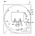
図2は、遊技盤5の概略正面図である。遊技盤5の盤面には、中央部に略円形の遊技領域Sが設定されている。遊技領域Sの周縁には、発射装置(図示しない)から発射された遊技球を、遊技盤5の上方(左側上部)に導くためのガイドレール23が配置されている。遊技領域Sには、多数本の障害釘25(図2には、一部のみ図示)が植設されている。遊技領域Sの左側上部からガイドレール23に沿って右斜め上方に向けて放たれた遊技球は、遊技盤5の盤面に沿って多数本の障害釘25の間を通って流下していく。   FIG. 2 is a schematic front view of the game board 5. On the board surface of the game board 5, a substantially circular game area S is set at the center. Around the periphery of the game area S, a guide rail 23 for guiding a game ball fired from a launching device (not shown) to the upper side (upper left side) of the game board 5 is arranged. A large number of obstacle nails 25 (only part of which are shown in FIG. 2) are planted in the game area S. A game ball released from the upper left side of the game area S toward the upper right along the guide rail 23 flows down along the board surface of the game board 5 through a number of obstacle nails 25.

遊技領域Sの中央部には、液晶表示ユニット24が配置されている。液晶表示ユニット24は、パチンコ機1の遊技中に、停止または変動中の演出図柄や所定のメッセージなどを表示する。
液晶表示ユニット24の下方には、第1特別図柄始動口26および第2特別図柄始動口27が上下に並べて配置されている。第1および第2特別図柄始動口26,27は、それぞれ、遊技盤5の盤面に沿って流下する遊技球を入球可能に設けている。第2特別図柄始動口27が電動チューリップ役物28を有しているのに対し、第1特別図柄始動口26は開閉手段等を有しない非作動式の入賞口である。
A liquid crystal display unit 24 is disposed at the center of the game area S. The liquid crystal display unit 24 displays an effect symbol, a predetermined message, or the like that is stopped or changed during the game of the pachinko machine 1.
Below the liquid crystal display unit 24, a first special symbol start port 26 and a second special symbol start port 27 are arranged vertically. Each of the first and second special symbol start ports 26 and 27 is provided with a game ball that flows down along the surface of the game board 5 so as to be able to enter. The second special symbol start port 27 has an electric tulip accessory 28, whereas the first special symbol start port 26 is a non-actuated winning port having no opening and closing means.

電動チューリップ役物28は、通常、各羽根の先端部が互いに接近した状態(狭窄状態)に窄められている。電動チューリップ役物28の狭窄状態では、遊技盤5の盤面に沿って流下する遊技球の第2特別図柄始動口27への入球が、第1特別図柄始動口26の入球役物と電動チューリップ役物28の一対の羽根とにより阻止されている。その結果、第2特別図柄始動口27が閉塞される。そして、電動チューリップ役物28が拡開された状態では、電動チューリップ役物28の各羽根が拡開されることにより、第2特別図柄始動口27に遊技球が入球可能になって、第2特別図柄始動口27が開放される。   The electric tulip accessory 28 is usually constricted in a state where the tip portions of the blades are close to each other (stenosis state). In the constricted state of the electric tulip accessory 28, the game ball flowing down along the board surface of the game board 5 enters the second special symbol starting port 27 and is electrically connected to the first special symbol starting port 26. It is blocked by the pair of blades of the tulip accessory 28. As a result, the second special symbol start port 27 is closed. In the state where the electric tulip accessory 28 is expanded, each of the blades of the electric tulip accessory 28 is expanded so that a game ball can enter the second special symbol starting port 27, and 2 The special symbol start port 27 is opened.

なお、電動チューリップ役物28の構成はこれに限定されるものではなく、次いで述べる可変入賞装置29と同様に、前後方向に出退する構成であってもよいし、たとえば、左右方向に延びる回動軸を中心として手前側に傾倒する構成であってもよい。
第1特別図柄始動口26または第2特別図柄始動口27に遊技球が入ると(入賞すると)、予め定める個数(第1特別図柄始動口26への遊技球入球に対してはたとえば5球、および第2特別図柄始動口27への遊技球入球に対してはたとえば3球)の賞球が、賞球払出装置56(図4参照)から払い出される。また、第1特別図柄始動口26または第2特別図柄始動口27への遊技球の入球(所定の始動条件)に伴って、特別遊技状態を発生させる大当りであるか否かを決定するための大当り抽選(当り遊技を発生させるか否かの抽選)が実行される。
Note that the configuration of the electric tulip accessory 28 is not limited to this, and may be configured to move in and out in the front-rear direction, similar to the variable winning device 29 described below, for example, a rotation extending in the left-right direction. The configuration may be such that it tilts toward the near side about the dynamic axis.
When a game ball enters the first special symbol start port 26 or the second special symbol start port 27 (wins), a predetermined number (for example, five balls for the game ball entering the first special symbol start port 26) , And, for example, three balls for a game ball entering the second special symbol start opening 27 are paid out from the prize ball payout device 56 (see FIG. 4). In addition, in order to determine whether or not it is a big hit that generates a special gaming state in accordance with the entering of a game ball (predetermined start condition) into the first special symbol start port 26 or the second special symbol start port 27. The big hit lottery (the lottery of whether or not to generate a winning game) is executed.

遊技領域Sには、遊技盤5の右下部に可変入賞装置29が配置されている。可変入賞装置29は第1および第2特別図柄始動口26,27の右方に配置されている。可変入賞装置29は、遊技領域Sの右下部に形成された、左右に長い平面視長方形状をなす大入賞口30と、大入賞口30を開閉可能な大入賞口開閉役物31とを備える。大入賞口30は、左右方向に関して、複数個(たとえば3〜4球)の遊技球が同時に入球可能なサイズに形成されている。大入賞口開閉役物31は、遊技盤5の盤面に沿った状態で大入賞口30を閉塞して、大入賞口30に遊技球が入るのを阻止することができる一方、この状態から後方に退避することにより、大入賞口30を開放して、大入賞口30上に流下してくる遊技球を大入賞口30内に導き入れることができる。なお、可変入賞装置29の構成はこれに限定されるものではなく、たとえば大入賞口30の下端縁に沿って配置された回動軸を中心に手前側に傾倒する構成であってもよいし、また、電動チューリップ役物28と同様に一対の羽根を有し、各羽根が狭窄状態と拡開状態との間で姿勢変更可能な構成であってもよい。   In the game area S, a variable winning device 29 is arranged at the lower right of the game board 5. The variable winning device 29 is arranged on the right side of the first and second special symbol starting ports 26 and 27. The variable winning device 29 includes a large winning opening 30 formed in the lower right portion of the game area S and having a rectangular shape in plan view that is long on the left and right sides, and a large winning opening opening / closing accessory 31 capable of opening and closing the large winning opening 30. . The big winning opening 30 is formed in a size that allows a plurality of (for example, 3 to 4) game balls to enter simultaneously in the left-right direction. The prize winning opening and closing accessory 31 can block the prize winning opening 30 in a state along the board surface of the game board 5 to prevent the game ball from entering the prize winning opening 30, while By retreating to the winning prize opening 30, it is possible to open the winning prize opening 30 and introduce the game balls flowing down on the winning prize opening 30 into the winning prize opening 30. The configuration of the variable winning device 29 is not limited to this. For example, the variable winning device 29 may be configured to tilt to the near side about a rotation shaft arranged along the lower edge of the big winning opening 30. Moreover, the structure which has a pair of blade | wing similarly to the electric tulip accessory 28, and each wing | blade can change an attitude | position between a narrowed state and an expanded state may be sufficient.

遊技領域Sには、液晶表示ユニット24の右方(遊技領域Sの右部)に、遊技盤5の盤面に沿って流下する遊技球が通過可能な普通図柄ゲート34が配置されている。
普通図柄ゲート34を遊技球が通過すると、第2特別図柄始動口27を開放するか否か(電動チューリップ役物28を拡開状態にするか否か)を決定するための普通図柄抽選が実行される。普通図柄抽選により第2特別図柄始動口27を開放すると決定される確率(普通図柄抽選の当選確率)は、後述する確率変動モード(確率変動遊技の実行時でかつサポート遊技の実行時)の非実行時ではたとえば1/100、確率変動モード中ではたとえば1/1.1である。
In the game area S, a normal symbol gate 34 through which a game ball flowing down along the surface of the game board 5 can pass is arranged on the right side of the liquid crystal display unit 24 (right part of the game area S).
When the game ball passes through the normal symbol gate 34, a normal symbol lottery for determining whether or not to open the second special symbol start port 27 (whether or not the electric tulip accessory 28 is in an expanded state) is executed. Is done. The probability determined that the second special symbol start opening 27 is opened by the normal symbol lottery (the winning probability of the normal symbol lottery) is a non-probability of the probability variation mode (when the probability variation game is executed and when the support game is executed) described later. For example, 1/100 at the time of execution, and 1 / 1.1 in the probability variation mode.

また、パチンコ機1には、特別遊技状態とは別の開放遊技である小当り遊技が用意されている。小当り遊技では、所定の開放時間(たとえば0.1(sec))だけ大入賞口30を1回開放させ、かつその後所定のインターバル(たとえば1.0(sec))を挟んで、所定の開放時間(たとえば0.1(sec))だけ大入賞口30を1回開放させる。
遊技盤5の盤面におけるガイドレール23の外側領域の右上隅部には、第1特別図柄表示手段(識別情報表示手段)35、第2特別図柄表示手段(識別情報表示手段)36および普通図柄表示手段37が配置されている。
Further, the pachinko machine 1 is provided with a small hit game which is an open game different from the special game state. In the small hit game, the special winning opening 30 is opened once for a predetermined opening time (for example, 0.1 (sec)), and after that, a predetermined interval (for example, 1.0 (sec)) is sandwiched between the predetermined opening time (for example, 0.1 (sec)). (sec)), the grand prize opening 30 is opened once.
A first special symbol display means (identification information display means) 35, a second special symbol display means (identification information display means) 36 and a normal symbol display are provided in the upper right corner of the outer area of the guide rail 23 on the board surface of the game board 5. Means 37 are arranged.

第1特別図柄表示手段35は、一または複数の特別図柄を変動動作可能な7セグメント式表示器等により構成されている。第1特別図柄表示手段35は、第1特別図柄始動口26に遊技球が入球することを条件に第1特別図柄が所定時間変動動作して、第1特別図柄始動口26への入球時に取得された大当り判定用乱数が、予め定められた大当り数値と一致する場合には所定の大当り用の第1特別図柄(特定表示結果)で、それ以外の場合にはハズレ用の第1特別図柄で停止する。大当り用の第1特別図柄として、確率変動遊技付きの大当りを示す確率変動図柄と、確率変動遊技が付かない大当りを示す非確率変動図柄とが用意されている。   The 1st special symbol display means 35 is comprised by the 7 segment type display etc. which can carry out the fluctuation | variation operation | movement of one or several special symbols. The first special symbol display means 35 moves the first special symbol for a predetermined time on condition that a game ball enters the first special symbol start port 26 and enters the first special symbol start port 26. If the random number for jackpot determination acquired at times matches the predetermined jackpot value, it is the first special symbol (specific display result) for the predetermined jackpot, otherwise it is the first special for lose Stop at the symbol. As the first special symbol for jackpot, a probability variation symbol indicating a jackpot with a probability variation game and a non-probability variation symbol indicating a jackpot without a probability variation game are prepared.

第2特別図柄表示手段36は、一または複数の特別図柄を変動動作可能な7セグメント式表示器等により構成されている。第2特別図柄表示手段36は、第2特別図柄始動口27に遊技球が入球することを条件に第2特別図柄が所定時間変動動作して、第2特別図柄始動口27への入球時に取得された大当り判定用乱数が、予め定められた大当り数値と一致する場合には所定の大当り用の第2特別図柄(特定表示結果)で、それ以外の場合にはハズレ用の第2特別図柄で停止する。大当り用の第2特別図柄として、確率変動遊技付きの大当りを示す確率変動図柄と、確率変動遊技が付かない大当りを示す非確率変動図柄とが用意されている。   The second special symbol display means 36 is constituted by a seven-segment display or the like that can perform variable operation of one or a plurality of special symbols. The second special symbol display means 36 moves the second special symbol for a predetermined time on condition that a game ball enters the second special symbol start port 27 and enters the second special symbol start port 27. If the random number for jackpot determination acquired at times matches the predetermined jackpot value, it is the second special symbol (specific display result) for the predetermined jackpot, otherwise it is the second special for lose Stop at the symbol. As the second special symbol for jackpot, a probability variation symbol indicating a jackpot with a probability variation game and a non-probability variation symbol indicating a jackpot without a probability variation game are prepared.

なお、第1および第2特別図柄表示手段35,36に、第1特別図柄の保留球数および第2特別図柄の保留球数をそれぞれ表示するための特別図柄用保留表示手段(図示しない)が設けられていてもよい。
普通図柄表示手段37は、普通図柄を変動動作するためのものであり、7セグメント表示器等を用いてなるべく目立たないように小さく設けられており、普通図柄ゲート34に遊技球が通過することを条件に普通図柄が所定時間変動動作して、普通図柄ゲート34に対する遊技球の通過時に取得された当り判定用乱数が予め定められた当り数値と一致する場合には所定の当り態様で、一致しない場合には所定のハズレ態様で停止させるようになっている。この普通図柄は、遊技者がその種類この普通図柄は、遊技者がその種類を容易に区別できないように特別な意味を持たない図柄が割り当てられることが望ましい。
Note that special symbol hold display means (not shown) for displaying the number of reserved balls of the first special symbol and the number of reserved balls of the second special symbol on the first and second special symbol display means 35 and 36, respectively. It may be provided.
The normal symbol display means 37 is for changing the normal symbol, and is provided as small as possible by using a 7-segment display or the like so that the game ball passes through the normal symbol gate 34. When the normal symbol fluctuates for a predetermined time according to the conditions and the random number for hit determination obtained when the game ball passes through the normal symbol gate 34 matches the predetermined hit value, it does not match in a predetermined hit mode. In some cases, the operation is stopped in a predetermined manner. This normal symbol is preferably assigned a symbol that does not have a special meaning so that the player cannot easily distinguish the type of the normal symbol.

大当り抽選の結果は、前述のように第1特別図柄表示手段35,36に表示されるが、特別図柄表示手段35,36だけでなく、液晶表示ユニット24にも表示される。
特別遊技状態(特定遊技状態)中は、大入賞口開閉役物31の揺動により大入賞口30が開放される。パチンコ機1には、第1および第2特別遊技状態(当り遊技)の合計2種類の特別遊技状態が用意されている。
第1特別遊技状態では、所定の時間(たとえば30(sec))が経過するまで、または大入賞口30に予め定める最大個数(たとえば10球)の遊技球が入球するまで、大入賞口30を開放するといった開放動作を1つのラウンドとして、このような開放動作がインターバル(たとえば1.0(sec))を挟んで所定の多数ラウンド(たとえば16ラウンド)行われる。1回の第1特別遊技状態において、遊技者が獲得可能な賞球は、たとえば約1600個(10(個/球)×10(球/ラウンド遊技)×16(ラウンド))である。
The result of the big hit lottery is displayed on the first special symbol display means 35 and 36 as described above, but is displayed not only on the special symbol display means 35 and 36 but also on the liquid crystal display unit 24.
During the special game state (specific game state) , the special prize opening 30 is opened by the swing of the special prize opening / closing accessory 31. The pachinko machine 1 is provided with a total of two types of special game states, the first and second special game states (winning games).
In the first special game state, the big prize opening 30 is kept until a predetermined time (for example, 30 (sec)) elapses or until the maximum number of game balls (for example, 10 balls) predetermined in the big prize opening 30 are entered. An opening operation such as opening a single round is performed, and such an opening operation is performed for a predetermined number of rounds (for example, 16 rounds) across an interval (for example, 1.0 (sec)). In one first special game state, the number of prize balls that a player can acquire is, for example, about 1600 (10 (pieces / ball) × 10 (ball / round game) × 16 (round)).

第2特別遊技状態では、所定の時間(たとえば30(sec))が経過するまで、または大入賞口30に予め定める最大個数の遊技球が入球するまで、大入賞口30を開放するといった開放動作を1つのラウンドとして、このような開放動作がインターバル(たとえば1.0(sec))を挟んで、複数ラウンド(たとえば2ラウンド)行われる。
なお、特別遊技状態は、2種類の態様に限られず、1種類であってもよいし、3種類以上であってもよい。また、各特別遊技状態の態様は、前述の態様に限られない。
In the second special game state, the special prize opening 30 is opened until a predetermined time (for example, 30 (sec)) elapses or until a predetermined number of game balls enter the special prize opening 30. With the operation as one round, such an opening operation is performed for a plurality of rounds (for example, two rounds) with an interval (for example, 1.0 (sec)) in between.
The special gaming state is not limited to two types of modes, and may be one type or three or more types. Moreover, the aspect of each special game state is not restricted to the above-mentioned aspect.

また、パチンコ機1には、特別遊技状態とは別の開放遊技である小当り遊技が用意されている。小当り遊技では、所定時間(たとえば0.5(sec))大入賞口30を開放するといった小当り開放動作を、インターバル(たとえば1.0(sec))を挟んで所定の少数回数(たとえば2回)行われる。
遊技者のハンドル操作により、発射装置(図示しない)から適度の勢いで発射された遊技球は、遊技領域Sの左上部分から右斜め上方に向けて放たれる。ハンドル操作により、遊技球の発射の狙い先を、遊技領域Sの左側上部と遊技領域Sの右側上部との間で打ち分けることができる。遊技領域Sの左上部分から放たれた遊技球は、遊技領域Sに植設された障害釘25の間を流下する。遊技盤5の盤面に沿って流下する遊技球のうち、第1もしくは第2特別図柄始動口26,27、大入賞口30、およびその他の入賞口(図示しない)のいずれにも入球しなかった遊技球(アウト球)は、遊技領域Sの下部に形成されたアウト口38から機内に入り、球回収部(図示しない)に回収される。
Further, the pachinko machine 1 is provided with a small hit game which is an open game different from the special game state. In the small hit game, a small hit release operation such as opening the big prize opening 30 for a predetermined time (for example, 0.5 (sec)) is performed a predetermined small number of times (for example, twice) with an interval (for example, 1.0 (sec)) interposed therebetween. .
A game ball launched at a moderate momentum from a launching device (not shown) by a player's handle operation is released from the upper left portion of the game area S diagonally upward to the right. The target of the game ball can be shot between the upper left portion of the game area S and the upper right portion of the game area S by operating the handle. The game ball released from the upper left portion of the game area S flows down between the obstacle nails 25 implanted in the game area S. Of the game balls flowing down along the board surface of the game board 5, do not enter any of the first or second special symbol start openings 26 and 27, the big winning opening 30, and other winning openings (not shown). The game ball (out ball) enters the machine through an out port 38 formed in the lower part of the game area S and is collected by a ball collection unit (not shown).

遊技領域Sにおける左上部分を狙って適度な速度で遊技球が発射されると、遊技領域Sの左上部分へと達した遊技球は、遊技領域Sの左半分(左上部分、左部分および左下部分)に植設された障害釘25によって、第1特別図柄始動口26付近に導かれる。つまり、発射位置を遊技領域Sの左側上部とすることにより、第1特別図柄始動口26に遊技球を入球させることができる。   When a game ball is launched at an appropriate speed aiming at the upper left part in the game area S, the game ball that has reached the upper left part of the game area S is the left half of the game area S (upper left part, left part and lower left part). ) Is guided to the vicinity of the first special symbol starting opening 26 by the obstacle nail 25 planted. That is, by setting the launch position to the upper left part of the game area S, it is possible to enter the game ball into the first special symbol starting port 26.

また、パチンコ機1では、特別遊技状態中において、遊技者によりいわゆる右打ち遊技(遊技領域Sの右側上部を狙って遊技球を発射させる遊技)が行われる。パチンコ機1は、いわゆる右打ち遊技を行えるように構成されている。ハンドル14の回転角度を最大角度とすると非常に強い勢いで遊技球が発射され、ガイドレール23に沿って遊技領域Sにおける左上部分から右斜め上方に向けて、遊技球が勢い良く放たれる。放たれた遊技球は、液晶表示ユニット24の上方を通って、遊技領域Sの盤面の右部分へと達し、遊技領域Sの右上部分に植設された障害釘25によって、可変入賞装置29の周囲に導かれる。そのため、開放動作中の可変入賞装置29の大入賞口30に遊技球を入球させ易い。   In the pachinko machine 1, a so-called right-handed game (a game in which a game ball is launched aiming at the upper right side of the game area S) is performed by the player during the special game state. The pachinko machine 1 is configured to perform a so-called right-handed game. When the rotation angle of the handle 14 is set to the maximum angle, the game ball is launched with a very strong momentum, and the game ball is released with great force from the upper left portion in the game area S toward the upper right side along the guide rail 23. The released game ball passes above the liquid crystal display unit 24 and reaches the right part of the board of the game area S. The obstacle nail 25 planted in the upper right part of the game area S causes the variable winning device 29 to Guided around. Therefore, it is easy to make a game ball enter the big winning opening 30 of the variable winning device 29 during the opening operation.

また、遊技領域Sの盤面の右部分へと達した遊技球は、遊技領域Sの右部分に植設された障害釘25によって、普通図柄ゲート34の周囲にも導かれる。そのため、普通図柄ゲート34への遊技球の通過頻度を高めることができる。また、普通図柄ゲート34を通過した遊技球は、遊技領域Sの右部分に植設された障害釘25によって第1特別図柄始動口26の周囲または第2特別図柄始動口27の周囲に導かれる。確率変動遊技中は、サポート遊技が併せて実行され、かつ普通図柄ゲート34への遊技球の通過頻度が高いために、第2特別図柄始動口27が頻繁に開放されている。したがって、確率変動遊技の実行時には、大入賞口30に遊技球を入球させ易いだけでなく、第2特別図柄始動口27にも遊技球を入球させることができる。   In addition, the game ball that has reached the right part of the board of the game area S is also guided to the periphery of the normal symbol gate 34 by the obstacle nail 25 implanted in the right part of the game area S. Therefore, the passing frequency of the game ball to the normal symbol gate 34 can be increased. Further, the game ball that has passed through the normal symbol gate 34 is guided around the first special symbol start port 26 or the second special symbol start port 27 by the obstacle nail 25 planted in the right part of the game area S. . During the probability variation game, the support game is also executed and the passing frequency of the game ball to the normal symbol gate 34 is high, so that the second special symbol start port 27 is frequently opened. Therefore, at the time of execution of the probability variation game, not only can the game ball be easily entered into the big prize opening 30, but also the game ball can be entered into the second special symbol starting port 27.

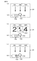
図3および図4は、液晶表示ユニット24の表示画面の表示内容の一例を示す図である。図3(a)に示すように、第1特別図柄表示手段35,36(図2参照)の変動動作中は、液晶表示ユニット24により演出図柄の変動動作が行われる。液晶表示ユニット24の表示画面内には、たとえば3つの図柄表示領域24L,24C,24Rが左右に並んで設定されている。そして、特別図柄表示手段35,36の変動動作中は、3つの図柄表示領域24L,24C,24Rにおいて、複数種の演出図柄(たとえば「0」〜「9」などの数字図柄や、キャラクタ図柄等)がたとえば上方から下方に向けてスクロール表示されることにより、演出図柄の変動動作が行われる。各図柄表示領域24L,24C,24Rに示す「↓」は、それらの図柄表示領域24L,24C,24Rの演出図柄が変動していることを示している。   3 and 4 are diagrams showing examples of display contents on the display screen of the liquid crystal display unit 24. FIG. As shown in FIG. 3A, during the changing operation of the first special symbol display means 35, 36 (see FIG. 2), the liquid crystal display unit 24 performs the changing operation of the effect symbol. In the display screen of the liquid crystal display unit 24, for example, three symbol display areas 24L, 24C, and 24R are set side by side. During the changing operation of the special symbol display means 35, 36, in the three symbol display areas 24L, 24C, 24R, a plurality of kinds of effect symbols (for example, numeric symbols such as “0” to “9”, character symbols, etc.) ) Is scroll-displayed from the upper side to the lower side, for example, so that the changing operation of the effect symbol is performed. “↓” shown in each of the symbol display areas 24L, 24C, 24R indicates that the effect symbols of the symbol display areas 24L, 24C, 24R are fluctuating.

3つの図柄表示領域24L,24C,24Rにおいて、変動開始後、所定時間が経過すると、3つの図柄表示領域24L,24C,24Rにおける変動動作が予め定める順序で停止されていき、最終的に、各図柄表示領域24L,24C,24Rに1つの演出図柄が停止した状態で表示されることにより、大当り抽選の結果を表す演出図柄の組合せが液晶表示ユニット24に表示される。   In the three symbol display areas 24L, 24C, 24R, when a predetermined time has elapsed after the start of the fluctuation, the fluctuation operations in the three symbol display areas 24L, 24C, 24R are stopped in a predetermined order. By displaying one effect symbol in the symbol display areas 24L, 24C, 24R in a stopped state, a combination of effect symbols representing the result of the big hit lottery is displayed on the liquid crystal display unit 24.

液晶表示ユニット24における演出態様には、液晶表示ユニット24の表示画面内の2つの図柄表示領域24L,24Rに演出図柄が停止表示され、残り1つの図柄表示領域24Cに演出図柄が停止表示されることによって大当りかハズレかが判明する、いわゆるリーチ状態を経ないで、3つの図柄表示領域24L,24C,24Rにハズレ用の演出図柄が表示される通常の変動動作と、リーチ状態を経た後に大当り用の演出図柄またはハズレ用の演出図柄が表示されるリーチパターンの変動動作とが用意されている。リーチパターンのリーチ演出には、たとえば、図8A等に示すように、ノーマルリーチ(第1リーチ演出)、ノーマルロングリーチ(ノーマルロング)、スーパーリーチ(第2リーチ演出)、スペシャルリーチ1(第2リーチ演出。図12A等で「スペリーチ1」と記載)、スペシャルリーチ2(第2リーチ演出。図12B等で「スペリーチ2」と記載)が用意されている。ノーマルリーチは、たとえば、残り1つの図柄表示領域における演出図柄が所定時間変動した後に停止するようなリーチである。ノーマルロングリーチは、たとえば、残り1つの図柄表示領域における演出図柄が、ノーマルリーチ時よりも長い時間変動した後に停止するようなリーチである。スーパーリーチは、所定のスーパーリーチキャラクタが登場して所定のスーパーリーチ演出を行うと共に、ノーマルロングリーチ時よりも長い時間変動した後に停止するようなリーチである。たとえば、スペシャルリーチ1およびスペシャルリーチ2は、所定のスペシャルリーチキャラクタが登場して所定のスペシャルリーチ演出を行うと共に、スーパーリーチ時よりも長い時間変動した後に停止するようなリーチである。スペシャルリーチ1では、変動動作が1回のみしか用意されていないのに対し、スペシャルリーチ2では、疑似変動を伴う疑似連演出が用意されている。疑似連演出は、変動動作が複数回(たとえば2回)あるかのような演出であり、1回目の変動が疑似変動とされている。 In the effect mode in the liquid crystal display unit 24, the effect symbols are stopped and displayed in the two symbol display areas 24L and 24R in the display screen of the liquid crystal display unit 24, and the effect symbols are stopped and displayed in the remaining one symbol display area 24C. This makes it possible to determine whether it is a big hit or a lost game, so that it does not go through the so-called reach state, and the normal fluctuation operation in which the effect symbols for the loss are displayed in the three symbol display areas 24L, 24C, 24R And a reach pattern changing operation in which an effect symbol for loss or an effect symbol for loss is displayed. For example, as shown in FIG. 8A, reach reach of the reach pattern includes normal reach ( first reach effect) , normal long reach (normal long), super reach (second reach effect) , special reach 1 ( second reach). Production: described as “Speach 1” in FIG. 12A and the like, and special reach 2 ( second reach production; described as “Speach 2” in FIG. 12B). The normal reach is, for example, a reach that stops after the effect symbol in the remaining one symbol display area fluctuates for a predetermined time. The normal long reach is a reach in which, for example, the effect symbol in the remaining one symbol display area stops after fluctuating for a longer time than in normal reach. The super reach is a reach in which a predetermined super reach character appears and performs a predetermined super reach effect, and stops after fluctuating for a longer time than in normal long reach. For example, special reach 1 and Special Reach 2 are given special reach character appeared performs predetermined special Lee Ji Starring unloading a reach as stops after change time longer than the time super reach. In Special Reach 1, a variable motion is prepared only once, whereas in Special Reach 2, a pseudo-continuous effect with pseudo variation is prepared. The pseudo continuous effect is an effect as if the fluctuating operation is performed a plurality of times (for example, twice), and the first fluctuation is a pseudo fluctuation.

なお、この実施形態では、スーパーリーチは、ノーマルリーチから発展する発展型のリーチであり、スぺシャルリーチ1およびスぺシャルリーチ2は、スーパーリーチから発展する発展型のリーチである。
図3に示すように、液晶表示ユニット24の下部分には、第1特別図柄用の保留数(すなわち、第1の始動情報記憶部61内の保留データ用エリアに記憶されている始動情報の数を表示するための第1の保留球数表示部(保留表示手段)101と、第2特別図柄用の保留数(すなわち、第2の始動情報記憶部62内の保留データ用エリアに記憶されている始動情報の数)を表示するための第2の保留球数表示部(保留表示手段)121とが設けられている。各保留数表示部101,121には、保留表示102が最大4個まで表示可能に設けられている。各保留表示102は、第1または第2特別図柄の変動動作に一対一対応で設けられており、たとえば円形をなしている。保留表示102が複数あるとき、保留表示102の表示位置(以下、「保留表示位置」という。)は、右側から左側に向けて、消化の早い順に並べられる。各保留表示102は、第1または第2特別図柄(演出図柄)の変動動作に一対一対応で設けられており、たとえば円形をなしている。液晶表示ユニット24の表示画面には、常に、各保留数表示部101,121が表示されているのであるが、図3および図4を除く各図において、液晶表示ユニット24の表示画面には、第2の保留数表示部121の図示を省略している。
In this embodiment, the super reach is an advanced reach that develops from the normal reach, and the special reach 1 and the special reach 2 are the evolved reach that develops from the super reach.
As shown in FIG. 3, in the lower part of the liquid crystal display unit 24, the number of reservations for the first special symbol (that is, the start information stored in the reserved data area in the first start information storage unit 61). The first reserved ball number display unit (holding display means) 101 for displaying the number and the number of reserved for the second special symbol (that is, stored in the reserved data area in the second start information storage unit 62) The number of the reserved information is displayed on the second number of reserved balls (holding display means) 121. On each of the number of held numbers display 101, 121, the number of held displays 102 is 4 at the maximum. Each hold display 102 is provided in a one-to-one correspondence with the changing operation of the first or second special symbol, for example, has a circular shape. , The display position of the hold display 102 (hereinafter, The “hold display positions” are arranged in the order of digestion from the right side to the left side.Each hold display 102 is provided in a one-to-one correspondence with the changing operation of the first or second special symbol (effect symbol). For example, the display screen of the liquid crystal display unit 24 always displays the number-of-holds display sections 101 and 121 in each figure except for FIGS. In the display screen of the liquid crystal display unit 24, the second reserved number display unit 121 is not shown.

パチンコ機1には、先読み保留変化予告(保留変化予告)が搭載されている。先読み保留変化予告では、第1または第2の始動情報記憶部61,62に記憶されている始動情報を図柄変動の開始前に先読み判定しておき、その判定結果に基づいて、その保留記憶に対応する保留表示102の保留表示態様(色)を、通常時(「白(デフォルト)」)と異なった態様(特別保留表示態様)で表示することにより、その保留記憶に対応する変動動作についての先読み信頼度を予告している。
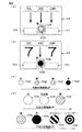
具体的には、保留数表示部101,121に表示される保留表示102は、その表示色によって、先読み信頼度(大当り信頼度の他、保留表示102の保留表示態様の変化回数や大当り信頼度の高い態様への期待度等を含む。)が異なっている。この実施形態では、図4(c)に示すように、保留表示102の保留表示態様として、「白(デフォルト)」、「青」、「緑」および「赤」の4態様が表示されている。つまり、「白(デフォルト)」の態様が通常保留表示態様であり、「青」、「緑」および「赤」の態様が特別保留表示態様である。図4(c)に示すように、「白」から「青」、「緑」、「赤」へと向かうに従って、先読み信頼度が高くなるように設定されている。
The pachinko machine 1 is equipped with a prefetch hold change notice (hold change notice) . In the prefetch hold change advance notice, the start information stored in the first or second start information storage units 61 and 62 is prefetched before the start of symbol variation, and the prestored hold is stored in the hold memory based on the determination result. By displaying the hold display mode (color) of the corresponding hold display 102 in a mode (special hold display mode) different from the normal time ("white (default)"), Pre-reading reliability is predicted.
Specifically, the hold display 102 displayed on the hold number display units 101 and 121 has a look-ahead reliability (the number of changes in the hold display mode of the hold display 102 and the jackpot reliability in addition to the jackpot reliability depending on the display color. Including the degree of expectation for a high aspect of. In this embodiment, as shown in FIG. 4C, four modes of “white (default)”, “blue”, “green”, and “red” are displayed as the hold display modes of the hold display 102. . That is, the “white (default)” mode is the normal hold display mode, and the “blue”, “green”, and “red” modes are the special hold display modes. As shown in FIG. 4C, the pre-reading reliability is set to increase from “white” to “blue”, “green”, and “red”.

パチンコ機1には、当該変動保留変化予告(特定表示)も搭載されている。具体的には、液晶表示ユニット24の下部分において左右方向の中央部には、現在変動中の第1または第2特別図柄(演出図柄)の変動動作に対応する始動情報を指し示す当該変動保留表示部(特定表示手段)103が表示されている。当該変動保留変化予告では、当該変動保留表示部103に表示される保留表示(以下、「当該変動保留表示」という。特定表示)104の保留表示態様(特定表示の態様)を、第1または第2特別図柄(演出図柄)の変動動作中に所定の保留表示態様に変化させることにより、現在変動している変動動作に対する大当り信頼度(当りの特別図柄が導出表示される信頼度)を表示している。 The pachinko machine 1 is also equipped with the change hold change notice ( specific indication ). Specifically, in the lower left portion of the liquid crystal display unit 24, in the center portion in the left-right direction, the change hold display indicating start information corresponding to the changing operation of the first or second special symbol (effect symbol) that is currently changing A part ( specific display means) 103 is displayed. In the variable hold change notice, the hold display mode ( specific display mode) of the hold display (hereinafter referred to as the “variable hold display”. Specific display ) 104 displayed on the variable hold display unit 103 is the first or first. by varying the predetermined hold display mode during variation operation of the second special symbol (performance symbol), display big hit reliability (the confidence that particular view pattern per is derived displayed) to variations operation currently fluctuates doing.

当該変動保留変化予告は、先読み保留変化予告の実行時には、実行中の先読み保留変化予告に連続した保留表示態様で開始される。すなわち、当該変動保留表示104における変動開始当初の保留表示態様は、シフト移行前の「保留1」の保留表示態様と同じである。また、当該変動保留表示104の保留表示態様の変化は、1回だけ変化するものに限られず、段階的に変化(以下、「ランクアップ」という場合がある。)することも可能である。この実施形態では、当該変動保留表示104の保留表示態様は、1段階〜3段階の範囲で変化する。   The variable hold change notice is started in a hold display mode continuous with the prefetch hold change notice being executed when the prefetch hold change notice is executed. That is, the hold display mode at the beginning of the change in the change hold display 104 is the same as the hold display mode of “hold 1” before shifting. In addition, the change in the hold display mode of the change hold display 104 is not limited to one that changes only once, but may change in stages (hereinafter also referred to as “ranking up”). In this embodiment, the hold display mode of the variable hold display 104 changes in a range of 1 to 3 steps.

具体的には、当該変動保留表示部103に表示される当該変動保留表示104は、その保留表示態様によって、その保留球に対応する大当り信頼度が異なっている。この実施形態では、図4(d)に示すように、当該変動保留表示104の保留表示態様(変動時表示態様)として、「白(デフォルト)」、「白点滅」(第1特別表示態様)、「青」(第1特別表示態様)、「緑」(第1特別表示態様)、「赤」(第1特別表示態様)、「デンジャー」(第1特別表示態様)および「レインボー(虹色)」(第2特別表示態様)の7態様が表示されている。図4(d)に示すように、「白」から「白点滅」、「青」、「緑」、「赤」、「デンジャー」および「レインボー」へと向かうに従って大当り信頼度が高くなるように設定されている。なお、「レインボー」は、大当り信頼度が100%(確定)の保留表示態様である。また、「白」と「白点滅」とは、同じ白色を表示しているのであるが、点灯態様が異なるので、この明細書では、互いに異なる保留表示態様として取り扱うこととする。当該変動保留変化予告における当該変動保留表示104の保留表示態様には、先読み保留変化予告による保留表示102にない保留表示態様(「白点滅」、「デンジャー」および「レインボー」)が含まれている。すなわち、先読み保留変化予告では表示可能であるが、当該変動保留変化予告では表示されない保留表示態様がある。 Specifically, the variable hold display 104 displayed on the variable hold display unit 103 has different jackpot reliability corresponding to the hold ball depending on the hold display mode. In this embodiment, as shown in FIG. 4 (d), “white (default)”, “white blinking” (first special display mode) as the hold display mode (display mode at the time of change) of the change hold display 104. , “Blue” (first special display mode) , “green” (first special display mode) , “red” (first special display mode) , “danger” (first special display mode) and “rainbow (rainbow color) 7) (second special display mode) is displayed. As shown in FIG. 4D, the big hit reliability is increased from “white” to “white blinking”, “blue”, “green”, “red”, “danger” and “rainbow”. Is set. “Rainbow” is a hold display mode with a big hit reliability of 100% (confirmed). In addition, “white” and “blinking white” display the same white color, but since the lighting modes are different, in this specification, they are treated as different hold display modes. The hold display mode of the variable hold display 104 in the variable hold change notice includes hold display forms (“blinking white”, “danger”, and “rainbow”) that are not in the hold display 102 by the prefetch hold change notice. . That is, there is a hold display mode that can be displayed in the prefetch hold change notice, but is not displayed in the variable hold change notice.

また、当該変動保留変化予告における変動開始当初の当該変動保留表示104の保留表示態様が「青」、「緑」および「赤」であるときの大当り信頼度は、それぞれ、先読み保留変化予告による保留表示102が「青」、「緑」および「赤」であるときの大当り信頼度と同程度に設定されている。
以下、図3(a)〜図3(c)および図4(a)および図4(b)を参照して、先読み保留変化予告および当該変動保留変化予告について説明する。また、以降の説明において、第1および第2の保留数表示部101,121の保留表示102の保留表示態様の変化(先読み保留変化予告)を、第1の保留数表示部101の保留表示102の保留表示態様の変化(第1の保留数表示部101を用いた先読み保留変化予告)を例に挙げて説明する。第2の保留数表示部121の保留表示102の保留表示態様の変化(第2の保留数表示部121を用いた先読み保留変化予告)については、第1の保留数表示部101の保留表示態様の変化の場合と同じであるので、説明を省略する。
The jackpot reliability when the hold display mode of the change hold display 104 at the beginning of change in the change hold change notice is “blue”, “green”, and “red”, respectively, It is set to the same degree as the big hit reliability when the display 102 is “blue”, “green” and “red”.
Hereinafter, the prefetch hold change notice and the variable hold change notice will be described with reference to FIGS. 3 (a) to 3 (c), 4 (a), and 4 (b). In the following description, the change in the hold display mode (prefetch hold change notice) of the hold display 102 of the first and second hold number display units 101 and 121 will be referred to as the hold display 102 of the first hold number display unit 101. A change in the hold display mode (pre-read hold change notice using the first hold number display unit 101) will be described as an example. About the change of the hold display mode of the hold display 102 of the second hold number display unit 121 (pre-read hold change notice using the second hold number display unit 121), the hold display mode of the first hold number display unit 101 Since this is the same as the case of the change, the description is omitted.

図3(a)に示すように、第1特別図柄(演出図柄)の変動動作中で、かつ第1特別図柄用の保留数が2個である状態で、第1特別図柄始動口26に新たな遊技球の入球があると、液晶表示ユニット24の第1の保留数表示部101の保留表示102の数が2個から3個に増やされる。このとき、入賞と同時に先読み保留変化予告が実行されて、第1の保留数表示部101の増加分(たとえば3個目)の保留表示102の保留表示態様(色)が、「白」ではなく、所定の保留表示態様(図3(a)ではたとえば「青」)を呈する。そして、所定の期間の経過後、液晶表示ユニット24に、たとえば、ハズレの演出図柄の組合せ(図3(b)では、たとえば「2」「3」「4」)が停止表示される。   As shown in FIG. 3 (a), the first special symbol start port 26 is newly operated while the first special symbol (effect symbol) is changing and the number of reserved symbols for the first special symbol is two. If there is an incoming game ball, the number of hold displays 102 in the first hold number display section 101 of the liquid crystal display unit 24 is increased from two to three. At this time, a pre-read hold change advance notice is executed simultaneously with the winning, and the hold display mode (color) of the hold display 102 of the increment (for example, the third) of the first hold number display unit 101 is not “white”. A predetermined hold display mode (for example, “blue” in FIG. 3A) is exhibited. Then, after the predetermined period has elapsed, for example, a combination of lost effect symbols (for example, “2”, “3”, “4” in FIG. 3B) is stopped and displayed on the liquid crystal display unit 24.

第1特別図柄(演出図柄)の変動動作の消化に伴い、液晶表示ユニット24の保留数表示部101,121の保留表示102の保留表示位置が、1つずつ右側にシフト移行する。そして、最も右側に位置する保留表示102が当該変動保留表示部103にシフト移行し、当該変動保留表示部103において当該変動保留表示104に置換される。
そして、図3(c)に示すように、保留表示102のシフト移行の際に、保留表示102の保留表示態様が変化することもある。図3(c)では、「保留3」の保留表示位置から「保留2」の保留表示位置へとシフト移行する保留表示102の色が「青」から「緑」になる場合を示している。
As the first special symbol (effect symbol) fluctuates, the hold display position of the hold display 102 of the hold number display units 101 and 121 of the liquid crystal display unit 24 shifts to the right one by one. Then, the hold display 102 located on the rightmost side shifts to the change hold display unit 103 and is replaced with the change hold display 104 in the change hold display unit 103.
Then, as shown in FIG. 3C, the hold display mode of the hold display 102 may change when the hold display 102 shifts. FIG. 3C shows a case where the color of the hold display 102 that shifts from the hold display position of “hold 3” to the hold display position of “hold 2” is changed from “blue” to “green”.

変動動作の消化が進み、図4(a)に示すように、前記の「緑」の保留表示102に対応する変動動作が変動開始される際には、この保留表示102に対応していた始動情報についての表示が、第1の保留数表示部101から当該変動保留表示部103にシフト移行し、当該変動保留表示部103において当該変動保留表示104として表示される。このとき、当該変動保留表示部103において表示される当該変動保留表示104の保留表示態様は、シフト移行前の「保留1」の保留表示102の保留表示態様と同じである。すなわち、保留表示102の保留表示態様(通常保留表示態様または特別保留表示態様)に対応する変動動作が変動開始される際には、その通常保留表示態様またはその特別保留表示態様(すなわち、通常表示態様または特別表示態様)が、当該変動保留表示104として継続して表示される。 When the fluctuation action is digested and the fluctuation action corresponding to the “green” hold display 102 starts to fluctuate as shown in FIG. 4A, the start corresponding to the hold display 102 is started. The information display shifts from the first hold number display unit 101 to the variable hold display unit 103, and is displayed as the variable hold display 104 in the variable hold display unit 103. At this time, the hold display mode of the variable hold display 104 displayed on the variable hold display unit 103 is the same as the hold display mode of the hold display 102 of “hold 1” before shifting. That is, when the fluctuating operation corresponding to the hold display mode (normal hold display mode or special hold display mode) of the hold display 102 starts to change, the normal hold display mode or the special hold display mode (that is, normal display) Mode or special display mode) is continuously displayed as the variable hold display 104.

そして、図4(b)に示すように、演出図柄の変動動作の途中において、当該変動保留表示104の保留表示態様が、大当り信頼度が上昇するように変化(以下、このような変化を「ランクアップ」という。)する。図4(b)では、当該変動保留表示104の保留表示態様がそれまでの「緑」から「青」に変化している。
この実施形態に示す先読み保留変化予告および当該変動保留変化予告は、変動動作の消化または時間の進行に伴って、先読み信頼度や大当り信頼度が上昇するかあるいは変わらないランクアップ型のものであり、先読み保留変化予告の先読み信頼度や当該変動保留変化予告の大当り信頼度が、変動動作の消化または時間の進行に伴って低下するような態様変化は行われない。
Then, as shown in FIG. 4B, during the changing operation of the production symbol, the hold display mode of the change hold display 104 changes so that the jackpot reliability increases (hereinafter, such a change is referred to as “ "Rank up"). In FIG. 4B, the hold display mode of the change hold display 104 changes from “green” to “blue”.
The pre-read hold change notice and the change hold change notice shown in this embodiment are of a rank-up type in which the pre-read reliability and the jackpot reliability increase or do not change with the digestion of the change operation or the progress of time. The aspect change is not performed such that the prefetch reliability of the prefetch hold change notice or the jackpot reliability of the change hold change notice decreases with the digestion of the change operation or the progress of time.

また、当該変動保留変化予告は、演出図柄の変動動作中に実行される。より具体的には、当該変動保留変化予告の実行タイミングとして、演出図柄の変動動作中(疑似連演出の1回目の変動動作を含む)の所定タイミング、ノーマルリーチ中の所定タイミング、およびスーパーリーチ中の所定タイミングのうちの少なくとも1回を例示できる。
なお、図3(a)では、入賞と同時に先読み保留変化予告が実行される場合を例に挙げて説明したが、むろん、先読み保留変化予告には、入賞時に保留表示102が態様変化せずに、シフト移行時に態様変化するものも含まれる。
The change hold change notice is executed during the changing operation of the effect symbol. More specifically, as the execution timing of the change hold change notice, the predetermined timing during the changing operation of the effect design (including the first changing operation of the pseudo-continuous effect), the predetermined timing during the normal reach, and the super reach At least one of the predetermined timings can be exemplified.
In FIG. 3A, the case where the pre-read hold change notice is executed simultaneously with the winning is described as an example, but of course, in the pre-read hold change notice, the hold display 102 does not change when winning. Also included are those that change mode during shift transition.

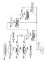
図4は、パチンコ機1の電気的構成を示すブロック図である。パチンコ機1は、AC24Vの交流電圧を受けて各種の直流電圧やシステムリセット信号などを出力する電源基板53と、当該パチンコ機1の統括的な動作制御を司る主制御基板40と、演出制御を司る演出制御基板41と、パチンコ機1から遊技球を払い出すための払出制御基板42とを備えている。主制御基板40には、主基板中継基板54を介して、電源基板53および払出制御基板42がそれぞれ接続されている。主制御基板40には、演出インターフェイス基板43を介して、演出制御基板41および液晶表示制御基板44がそれぞれ接続されている。電源基板53は、演出インターフェイス基板43を介して、演出制御基板41および液晶表示制御基板44にそれぞれ接続されている。第1演出操作ボタン13および第2演出操作ボタン12からの操作入力信号は、それぞれ、演出インターフェイス基板43を介して演出制御基板41に入力されるようになっている。   FIG. 4 is a block diagram showing an electrical configuration of the pachinko machine 1. The pachinko machine 1 receives an AC voltage of 24V AC and outputs various DC voltages, system reset signals, etc., a main control board 40 that controls the overall operation of the pachinko machine 1, and directing control. There is provided an effect control board 41 for controlling, and a payout control board 42 for paying out game balls from the pachinko machine 1. The main control board 40 is connected to the power supply board 53 and the payout control board 42 via the main board relay board 54. An effect control board 41 and a liquid crystal display control board 44 are connected to the main control board 40 via an effect interface board 43, respectively. The power supply board 53 is connected to the effect control board 41 and the liquid crystal display control board 44 via the effect interface board 43. Operation input signals from the first effect operation button 13 and the second effect operation button 12 are input to the effect control board 41 via the effect interface board 43, respectively.

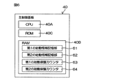
主制御基板40は、CPU40A(始動情報取得手段、抽選手段、先読み判定手段)、RAM40BおよびROM40Cを含むマイクロコンピュータを備えている。主制御基板40には、演出制御基板41や払出制御基板42などに制御コマンドを送信するためのコマンド送信部が設けられている。
主制御基板40には、第1および第2特別図柄表示手段35,36ならびに普通図柄表示手段37が制御対象として接続されている。また、主制御基板40には、第1および第2特別図柄始動口26,27(図2参照)への入球をそれぞれ検出するための第1および第2特別図柄始動口入球センサ46,47が接続されており、第1および第2特別図柄始動口入球センサ46,47からの検出出力が直接入力されるようになっている。
The main control board 40, CPU 40A (start information obtaining unit, extract player stage, pre-read determination means), and a microcomputer including a RAM40B and ROM40C. The main control board 40 is provided with a command transmission unit for transmitting a control command to the effect control board 41, the payout control board 42, and the like.
The main control board 40 is connected with first and second special symbol display means 35 and 36 and a normal symbol display means 37 as control targets. Further, the main control board 40 includes first and second special symbol start opening sensor 46 for detecting the entrance to the first and second special symbol start openings 26 and 27 (see FIG. 2), respectively. 47 is connected, and the detection outputs from the first and second special symbol start-up entrance sensors 46 and 47 are directly inputted.

また、主制御基板40には、遊技盤中継基板45を介して、普通図柄ゲート34(図2参照)を遊技球が通過したことを検出するための普通ゲート通過センサ48からの検出出力、可変入賞装置29の大入賞口30(図2参照)に遊技球が入ったことを検出するための大入賞口入球センサ49からの検出出力が、それぞれ入力されるようになっている。
また、主制御基板40には、遊技盤中継基板45を介して、電動チューリップ役物28(図2参照)を駆動するための電動チューリップ駆動機構(たとえばソレノイド類を含む)51や、大入賞口開閉役物31(図2参照)を開閉駆動するための大入賞口開閉機構(たとえばソレノイド類を含む)52等が制御対象として接続されている。
The main control board 40 has a detection output from a normal gate passage sensor 48 for detecting that a game ball has passed through the normal symbol gate 34 (see FIG. 2) via the game board relay board 45, and is variable. The detection outputs from the big prize opening ball entrance sensor 49 for detecting that a game ball has entered the big prize opening 30 (see FIG. 2) of the winning device 29 are respectively input.
The main control board 40 has an electric tulip driving mechanism (including solenoids, for example) 51 for driving the electric tulip accessory 28 (see FIG. 2) via the game board relay board 45, and a grand prize opening. A prize winning opening and closing mechanism (including solenoids, for example) 52 for opening and closing the opening and closing accessory 31 (see FIG. 2) is connected as a control target.

演出制御基板41は、演出インターフェイス基板43を介して主制御基板40に接続されている。演出制御基板41は、CPU保留変化予告制御手段、特定表示予告制御手段)41A、RAM41BおよびROM41Cを含むマイクロコンピュータを備えている。演出制御基板41には、液晶表示制御基板44などに制御コマンドを送信するためのコマンド送信部が設けられている。演出制御基板41には、演出インターフェイス基板43を介して液晶表示制御基板44が接続されている。 The effect control board 41 is connected to the main control board 40 via the effect interface board 43. The effect control board 41 includes a microcomputer including a CPU ( pending change notice control means, specific display notice control means) 41A, RAM 41B and ROM 41C. The effect control board 41 is provided with a command transmission unit for transmitting a control command to the liquid crystal display control board 44 or the like. A liquid crystal display control board 44 is connected to the effect control board 41 via an effect interface board 43.

演出制御基板41には、パチンコ機1の本体(前扉等)前面等に配置されるスピーカ90や遊技ランプ91が、演出インターフェイス基板43および枠中継基板55を介して、制御対象としてそれぞれ接続されている。
払出制御基板42は、CPU42A、RAM42B、ROM42C等を含むマイクロコンピュータを備えており、主制御基板40に接続されている。払出制御基板42には、賞球払出装置56が制御対象として接続されている。
Speakers 90 and game lamps 91 arranged on the front surface of the main body (front door, etc.) of the pachinko machine 1 are connected to the effect control board 41 as control targets via the effect interface board 43 and the frame relay board 55, respectively. ing.
The payout control board 42 includes a microcomputer including a CPU 42A, a RAM 42B, a ROM 42C, and the like, and is connected to the main control board 40. A prize ball payout device 56 is connected to the payout control board 42 as a control target.

演出制御基板41は、主制御基板40からの制御コマンドに基づいて、液晶表示ユニット24やスピーカ90等の演出装置の演出内容を決定し、その演出内容が記された制御コマンドを制御対象に対して出力する。たとえば液晶表示ユニット24の制御については、液晶表示制御基板44には、演出制御基板41からの制御コマンドが、演出インターフェイス基板43を介して与えられ、与えられた制御コマンド(この場合、液晶制御用の制御コマンド)の内容に基づいて、液晶表示制御基板44は液晶表示ユニット24の表示を制御する。   The production control board 41 determines the production content of the production device such as the liquid crystal display unit 24 and the speaker 90 based on the control command from the main control board 40, and the control command on which the production content is written is controlled. Output. For example, regarding the control of the liquid crystal display unit 24, a control command from the effect control board 41 is given to the liquid crystal display control board 44 via the effect interface board 43, and the given control command (in this case, for liquid crystal control). The liquid crystal display control board 44 controls the display of the liquid crystal display unit 24 based on the content of the control command.

液晶表示制御基板44は、CPU44A、RAM44BおよびROM424Cを含むマイクロコンピュータを備えている。液晶表示制御基板44には液晶表示ユニット24が制御対象として接続されている。
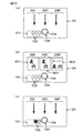
図6は、主制御基板40の電気的構成を示すブロック図である。図2、図4および図6を参照しつつ、主制御基板40の構成について説明する。
主制御基板40のRAM40Bには、第1の始動情報記憶部61、第2の始動情報記憶部62、第1の始動保留カウンタ63および第2の始動保留カウンタ64が設けられている。
The liquid crystal display control board 44 includes a microcomputer including a CPU 44A, a RAM 44B, and a ROM 424C. The liquid crystal display unit 24 is connected to the liquid crystal display control board 44 as a control target.
FIG. 6 is a block diagram showing an electrical configuration of the main control board 40. The configuration of the main control board 40 will be described with reference to FIGS. 2, 4 and 6.
The RAM 40B of the main control board 40 is provided with a first start information storage unit 61, a second start information storage unit 62, a first start hold counter 63, and a second start hold counter 64.

第1の始動情報記憶部61には、第1特別図柄始動口26への遊技球入球に対して実行される大当り抽選の結果が格納される。第1の始動情報記憶部61には、大当り判定用乱数(第1抽選の結果を示す情報)、特別図柄用乱数(確率変動遊技の実行の有無を決定するための情報)、および変動パターン用乱数(以上の各乱数をまとめて「始動情報」という。)が最大でたとえば5つまで記憶可能である。具体的には、第1の始動情報記憶部61には、始動情報を記憶するための記憶エリアが5つ設けられている。これらの記憶エリアを、それぞれ、第0エリア(エリア0)、第1エリア(エリア1)、第2エリア(エリア2)、第3エリア(エリア3)および第4エリア(エリア4)ということにする。   The first start information storage unit 61 stores the result of the big hit lottery executed for the game ball entering the first special symbol start port 26. The first start-up information storage unit 61 includes a jackpot determination random number (information indicating the result of the first lottery), a special symbol random number (information for determining whether or not a probability variation game is executed), and a variation pattern For example, a maximum of five random numbers (collectively referred to as “starting information”) can be stored. Specifically, the first start information storage unit 61 is provided with five storage areas for storing start information. These storage areas are referred to as area 0 (area 0), area 1 (area 1), area 2 (area 2), area 3 (area 3) and area 4 (area 4), respectively. To do.

第1の始動情報記憶部61の第0エリアは、実行対象となっている始動情報を記憶するための領域である。以下において、「実行データ用エリア」という場合がある。
第1の始動情報記憶部61の第1エリア〜第4エリアの4つの領域は、実行が保留されている始動情報を記憶するための領域である。この第1エリア〜第4エリアを総称する場合には、「保留データ用エリア」という場合がある。
The 0th area of the first start information storage unit 61 is an area for storing start information that is an execution target. Hereinafter, it may be referred to as an “execution data area”.
The four areas from the first area to the fourth area of the first start-up information storage unit 61 are areas for storing start-up information whose execution is suspended. When the first area to the fourth area are collectively referred to, it may be referred to as a “holding data area”.

第1特別図柄始動口26に遊技球が入ったときには、第1の始動情報記憶部61内の保留データ用エリアに、始動情報が記憶される。具体的には、第1エリアが空であれば第1エリアに始動情報が記憶され、第1エリアが空でなく第2エリアが空であれば第2エリアに始動情報が記憶され、第1および第2エリアが空でなく第3エリアが空であれば第3エリアに始動情報が記憶され、第1〜第3エリアが空でなく第4エリアが空であれば第4エリアに始動情報が記憶される。   When a game ball enters the first special symbol start opening 26, start information is stored in the reserved data area in the first start information storage unit 61. Specifically, if the first area is empty, the start information is stored in the first area. If the first area is not empty and the second area is empty, the start information is stored in the second area. If the second area is not empty and the third area is empty, the start information is stored in the third area, and if the first to third areas are not empty and the fourth area is empty, the start information is stored in the fourth area. Is memorized.

第1の始動情報記憶部61の第0エリアに始動情報が記憶されておらず、かつ特別遊技状態中でない状態であることを条件に、第1の始動情報記憶部61の第1〜第4エリアに記憶されている始動情報が、それぞれ、第1の始動情報記憶部61の第0〜第3エリアに移行されるとともに、第4エリアが空にされる。そして、第1の始動情報記憶部61の第0エリア(実行データ用エリア)に移行された始動情報が実行される。   On the condition that no starting information is stored in the 0th area of the first starting information storage unit 61 and that the special gaming state is not set, the first to fourth of the first starting information storage unit 61 The start information stored in the area is shifted to the 0th to third areas of the first start information storage unit 61, and the fourth area is emptied. Then, the start information transferred to the 0th area (execution data area) of the first start information storage unit 61 is executed.

第1の始動情報記憶部61内の保留データ用エリア(第1〜第4エリア)に記憶されている始動情報の数は、第1の始動保留カウンタ63に記憶される。
第1の始動情報記憶部61の第0エリア(実行データ用エリア)に始動情報が移行されると、当該始動情報に対応する特別変動動作が開始される。当該変動動作の開始時には、その始動情報に含まれる大当り判定用乱数が、大当り数値と一致するか、小当り数値と一致するか、あるいは大当り数値または小当り数値のいずれとも一致しないかが判定される。CPU40Aは、大当り判定用乱数が大当り数値と一致するときは、その後特別遊技状態が実行される。特別遊技状態中は、2バイト構成の条件装置作動フラグの値が、00[H]から5A[H]に切り換えられる。また、CPU40Aは、大当り判定用乱数が小当り数値と一致するときは、その後小当り遊技が実行される。小当り遊技の実行中には、2バイト構成の小当り中フラグの値が、00[H]から5A[H]に切り換えられる。
The number of start information stored in the hold data area (first to fourth areas) in the first start information storage unit 61 is stored in the first start hold counter 63.
When the start information is transferred to the 0th area (execution data area) of the first start information storage unit 61, a special variation operation corresponding to the start information is started. At the start of the fluctuating motion, it is determined whether the big hit determination random number included in the start information matches the big hit value, the small hit value, or the big hit value or the small hit value. The When the jackpot determination random number matches the jackpot value, the CPU 40A subsequently executes the special gaming state. During the special game state, the value of the 2-byte configuration condition device operation flag is switched from 00 [H] to 5A [H]. Further, when the big hit determination random number matches the small hit value, the CPU 40A executes the small hit game thereafter. During the execution of the small hit game, the value of the small hit medium flag having a 2-byte configuration is switched from 00 [H] to 5A [H].

第2の始動情報記憶部62には、第2特別図柄始動口27への遊技球入球に対して実行される大当り抽選の結果が格納される。第2の始動情報記憶部62には、大当り判定用乱数(第1抽選の結果を示す情報)、特別図柄用乱数(確率変動遊技の実行の有無を決定するための情報)、および変動パターン用乱数(以上の各乱数をまとめて「始動情報」という。)が最大でたとえば5つまで記憶可能である。具体的には、第2の始動情報記憶部62には、始動情報を記憶するための記憶エリアが5つ設けられている。これらの記憶エリアを、それぞれ、第0エリア(エリア0)、第1エリア(エリア1)、第2エリア(エリア2)、第3エリア(エリア3)および第4エリア(エリア4)ということにする。   The second start information storage unit 62 stores the result of the big hit lottery executed for the game ball entering the second special symbol start port 27. The second start-up information storage unit 62 includes a jackpot determination random number (information indicating the result of the first lottery), a special symbol random number (information for determining whether or not the probability variation game is executed), and a variation pattern For example, a maximum of five random numbers (collectively referred to as “starting information”) can be stored. Specifically, the second start information storage unit 62 is provided with five storage areas for storing start information. These storage areas are referred to as area 0 (area 0), area 1 (area 1), area 2 (area 2), area 3 (area 3) and area 4 (area 4), respectively. To do.

第2の始動情報記憶部62の第0エリアは、実行対象となっている始動情報を記憶するための領域である。以下において、「実行データ用エリア」という場合がある。
第2の始動情報記憶部62の第1エリア〜第4エリアの4つの領域は、実行が保留されている始動情報を記憶するための領域である。この第1エリア〜第4エリアを総称する場合には、「保留データ用エリア」という場合がある。
The 0th area of the 2nd starting information storage part 62 is an area for memorizing starting information used as an execution object. Hereinafter, it may be referred to as an “execution data area”.
The four areas from the first area to the fourth area of the second start-up information storage unit 62 are areas for storing start-up information whose execution is suspended. When the first area to the fourth area are collectively referred to, it may be referred to as a “holding data area”.

第2特別図柄始動口27に遊技球が入ったときには、第2の始動情報記憶部62内の保留データ用エリアに、始動情報が記憶される。具体的には、第1エリアが空であれば第1エリアに始動情報が記憶され、第1エリアが空でなく第2エリアが空であれば第2エリアに始動情報が記憶され、第1および第2エリアが空でなく第3エリアが空であれば第3エリアに始動情報が記憶され、第1〜第3エリアが空でなく第4エリアが空であれば第4エリアに始動情報が記憶される。   When a game ball enters the second special symbol start port 27, start information is stored in the reserved data area in the second start information storage unit 62. Specifically, if the first area is empty, the start information is stored in the first area. If the first area is not empty and the second area is empty, the start information is stored in the second area. If the second area is not empty and the third area is empty, the start information is stored in the third area, and if the first to third areas are not empty and the fourth area is empty, the start information is stored in the fourth area. Is memorized.

第2の始動情報記憶部62の第0エリアに始動情報が記憶されておらず、かつ特別遊技状態中でない状態であることを条件に、第2の始動情報記憶部62の第1〜第4エリアに記憶されている始動情報が、それぞれ、第2の始動情報記憶部62の第0〜第3エリアに移行されるとともに、第4エリアが空にされる。そして、第2の始動情報記憶部62の第0エリア(実行データ用エリア)に移行された始動情報が実行される。   On the condition that no start information is stored in the 0th area of the second start information storage unit 62 and the game is not in the special game state, the first to fourth of the second start information storage unit 62 The start information stored in the area is shifted to the 0th to third areas of the second start information storage unit 62, and the fourth area is emptied. Then, the start information transferred to the 0th area (execution data area) of the second start information storage unit 62 is executed.

第2の始動情報記憶部62内の保留データ用エリア(第1〜第4エリア)に記憶されている始動情報の数は、第2の始動保留カウンタ64に記憶される。
第2の始動情報記憶部62の第0エリア(実行データ用エリア)に始動情報が移行されると、当該始動情報に対応する特別変動動作が開始される。当該変動動作の開始時には、その始動情報に含まれる大当り判定用乱数が、大当り数値と一致するか、小当り数値と一致するか、あるいは大当り数値または小当り数値のいずれとも一致しないかが判定される。CPU40Aは、大当り判定用乱数が大当り数値と一致するときは、その後特別遊技状態が実行される。特別遊技状態中は、2バイト構成の条件装置作動フラグの値が、00[H]から5A[H]に切り換えられる。また、CPU40Aは、大当り判定用乱数が小当り数値と一致するときは、その後小当り遊技が実行される。小当り遊技の実行中には、2バイト構成の小当り中フラグの値が、00[H]から5A[H]に切り換えられる。
The number of start information stored in the hold data area (first to fourth areas) in the second start information storage unit 62 is stored in the second start hold counter 64.
When the start information is transferred to the 0th area (execution data area) of the second start information storage unit 62, a special variation operation corresponding to the start information is started. At the start of the fluctuating motion, it is determined whether the big hit determination random number included in the start information matches the big hit value, the small hit value, or the big hit value or the small hit value. The When the jackpot determination random number matches the jackpot value, the CPU 40A subsequently executes the special gaming state. During the special game state, the value of the 2-byte configuration condition device operation flag is switched from 00 [H] to 5A [H]. Further, when the big hit determination random number matches the small hit value, the CPU 40A executes the small hit game thereafter. During the execution of the small hit game, the value of the small hit medium flag having a 2-byte configuration is switched from 00 [H] to 5A [H].

図7は、演出制御基板41の電気的構成を示すブロック図である。図2、図4および図7を参照しつつ、演出制御基板41の構成について説明する。
図7に示すように、演出インターフェイス基板43には、バッファ回路65,66などが実装されている。演出制御基板41には、主制御基板40から出力された制御コマンドが演出インターフェイス基板43のバッファ回路65を介して入力されるようになっている。
FIG. 7 is a block diagram showing an electrical configuration of the effect control board 41. The configuration of the effect control board 41 will be described with reference to FIGS. 2, 4, and 7.
As shown in FIG. 7, buffer circuits 65 and 66 are mounted on the effect interface board 43. The control command output from the main control board 40 is input to the effect control board 41 via the buffer circuit 65 of the effect interface board 43.

演出制御基板41のCPU41Aは、制御コマンド(に含まれる変動パターンコマンド(A0**[H]))に基づいて演出抽選を行い、変動パターンコマンド(A0**[H])で特定される演出概要に基づいて具体的な演出内容を決定する。この演出内容は、液晶表示ユニット24への表示画像などの表示内容に限られず、ランプ類の点滅によるランプ演出の内容やスピーカ群からの発音などの音声内容を含む。演出制御基板41から送信される制御コマンドは、バッファ回路66を経由して、そのまま液晶表示制御基板44や音声を出力するための音声制御基板などに出力される。   The CPU 41A of the effect control board 41 performs an effect lottery based on the control command (variation pattern command (A0 ** [H]) included therein), and the effect specified by the variation pattern command (A0 ** [H]). Based on the outline, specific production contents are determined. This effect content is not limited to the display content such as the display image on the liquid crystal display unit 24, but includes the content of the lamp effect caused by the flashing of the lamps and the sound content such as the pronunciation from the speaker group. The control command transmitted from the effect control board 41 is output via the buffer circuit 66 to the liquid crystal display control board 44 or a voice control board for outputting voice as it is.

演出制御基板41のROM41Cは、抽選表記憶部75と、保留態様変化パターン記憶部78とを含む。抽選表記憶部75は、先読み保留変化予告用の抽選表や当該変動保留変化予告用の抽選表を含む々の抽選表(抽選テーブル)を記憶する。保留態様変化パターン記憶部78に記憶される保留態様変化パターンは、後述する第2実施形態の保留態様変化パターンPD(図37参照)と同等のパターンを含む。   The ROM 41 </ b> C of the effect control board 41 includes a lottery table storage unit 75 and a hold mode change pattern storage unit 78. The lottery table storage unit 75 stores lottery tables (lottery tables) including a lottery table for pre-reading hold change notice and a lottery table for change hold notice of change. The hold mode change pattern stored in the hold mode change pattern storage unit 78 includes a pattern equivalent to a hold mode change pattern PD (see FIG. 37) of the second embodiment to be described later.

演出制御基板41のRAM41Bには、第1の保留メモリ71と、第2の保留メモリ72と、第1の保留カウンタ73と、第2の保留カウンタ74と、先読み保留変化予告フラグ76と、保留態様変化パターン記憶部77とが設けられている。第1の保留メモリ71には、第1の始動情報記憶部61に記憶されている始動情報の内容を表す先読み情報が、第1の始動情報記憶部61と対応する形で記憶されている。第2の保留メモリ72には、第2の始動情報記憶部62に記憶されている始動情報の内容を表す先読み情報が、第2の始動情報記憶部62と対応する形で記憶されている。   In the RAM 41B of the effect control board 41, a first hold memory 71, a second hold memory 72, a first hold counter 73, a second hold counter 74, a prefetch hold change notice flag 76, a hold An aspect change pattern storage unit 77 is provided. The first hold memory 71 stores pre-read information indicating the contents of the start information stored in the first start information storage unit 61 in a form corresponding to the first start information storage unit 61. In the second holding memory 72, pre-read information indicating the contents of the start information stored in the second start information storage unit 62 is stored in a form corresponding to the second start information storage unit 62.

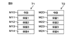
図8は、第1および第2の保留メモリ71,72の構成を説明する図である。
第1の保留メモリ71には、2バイトのデータからなる先読み情報をそれぞれ記憶するための記憶エリアが5つ設けられている。これらの記憶エリアを、それぞれ、第0先読み記憶エリアM10、第1先読み記憶エリアM11、第2先読み記憶エリアM12、第3先読み記憶エリアM13および第4先読み記憶エリアM14ということにする。
FIG. 8 is a diagram illustrating the configuration of the first and second reserved memories 71 and 72.
The first reserved memory 71 is provided with five storage areas for storing pre-read information composed of 2-byte data. These storage areas are referred to as a 0th prefetch storage area M10, a first prefetch storage area M11, a second prefetch storage area M12, a third prefetch storage area M13, and a fourth prefetch storage area M14, respectively.

第1の保留メモリ71の第0先読み記憶エリアM10は、第1の始動情報記憶部61の第0エリアに対応している。第1の保留メモリ71の第1先読み記憶エリアM11は、第1の始動情報記憶部61の第1エリアに対応している。第1の保留メモリ71の第2先読み記憶エリアM12は、第1の始動情報記憶部61の第2エリアに対応している。第1の保留メモリ71の第3先読み記憶エリアM13は、第1の始動情報記憶部61の第3エリアに対応している。第1の保留メモリ71の第4先読み記憶エリアM14は、第1の始動情報記憶部61の第4エリアに対応している。   The 0th prefetch storage area M10 of the first reserved memory 71 corresponds to the 0th area of the first startup information storage unit 61. The first look-ahead storage area M11 of the first reserved memory 71 corresponds to the first area of the first start-up information storage unit 61. The second prefetch storage area M12 of the first reserved memory 71 corresponds to the second area of the first start information storage unit 61. The third look-ahead storage area M13 of the first reserved memory 71 corresponds to the third area of the first start-up information storage unit 61. The fourth look-ahead storage area M14 of the first reserved memory 71 corresponds to the fourth area of the first start-up information storage unit 61.

第2の保留メモリ72には、2バイトのデータからなる先読み情報をそれぞれ記憶するための記憶エリアが5つ設けられている。これらの記憶エリアを、それぞれ、第0先読み記憶エリアM20、第1先読み記憶エリアM21、第2先読み記憶エリアM22、第3先読み記憶エリアM23および第4先読み記憶エリアM24ということにする。
第2の保留メモリ72の第0先読み記憶エリアM20は、第2の始動情報記憶部62の第0エリアに対応している。第2の保留メモリ72の第1先読み記憶エリアM21は、第2の始動情報記憶部62の第1エリアに対応している。第2の保留メモリ72の第2先読み記憶エリアM22は、第2の始動情報記憶部62の第2エリアに対応している。第2の保留メモリ72の第3先読み記憶エリアM23は、第2の始動情報記憶部62の第3エリアに対応している。第2の保留メモリ72の第4先読み記憶エリアM24は、第2の始動情報記憶部62の第4エリアに対応している。
The second reserved memory 72 is provided with five storage areas for storing pre-read information composed of 2-byte data. These storage areas are referred to as a 0th prefetch storage area M20, a first prefetch storage area M21, a second prefetch storage area M22, a third prefetch storage area M23, and a fourth prefetch storage area M24, respectively.
The 0th prefetch storage area M20 of the second reserved memory 72 corresponds to the 0th area of the second startup information storage unit 62. The first look-ahead storage area M21 of the second reserved memory 72 corresponds to the first area of the second startup information storage unit 62. The second look-ahead storage area M22 of the second reserved memory 72 corresponds to the second area of the second startup information storage unit 62. The third look-ahead storage area M23 of the second reserved memory 72 corresponds to the third area of the second startup information storage unit 62. The fourth look-ahead storage area M24 of the second reserved memory 72 corresponds to the fourth area of the second start-up information storage unit 62.

図7に戻り、第1の保留カウンタ73は、第1の保留メモリ71の保留領域M11〜M14に記憶されている先読み情報の個数を記憶するためのものである。第1の保留カウンタ73の値に基づいて、液晶表示ユニット24の第1の保留数表示部101(図3等参照)における第1特別図柄用の保留数の表示が行われる。
第2の保留カウンタ74は、第2の保留メモリ72の保留領域M21〜M24に記憶されている先読み情報の個数を記憶するためのものである。第2の保留カウンタ74の値に基づいて、液晶表示ユニット24の第2の保留数表示部102(図3等参照)における第2特別図柄用の保留数の表示が行われる。
Returning to FIG. 7, the first hold counter 73 is for storing the number of pre-read information stored in the hold areas M <b> 11 to M <b> 14 of the first hold memory 71. Based on the value of the first holding counter 73, the holding number for the first special symbol is displayed on the first holding number display unit 101 (see FIG. 3 and the like) of the liquid crystal display unit 24.
The second hold counter 74 is for storing the number of prefetch information stored in the hold areas M21 to M24 of the second hold memory 72. Based on the value of the second hold counter 74, the hold number for the second special symbol is displayed on the second hold number display section 102 (see FIG. 3 and the like) of the liquid crystal display unit 24.

先読み保留変化予告フラグ76は、先読み保留変化予告の実行中であるか否かを記憶しておくためのものである。先読み保留変化予告フラグ76の値は、先読み保留変化予告の実行中にたとえば5A[H]に設定され、また、先読み保留変化予告の非実行時にたとえば00[H]に設定されている。
保留態様変化パターン記憶部77には、実行すると決定された先読み保留変化予告用の保留態様変化パターンや、実行すると決定された当該変動保留変化予告用の保留態様変化パターンが記憶されている。また、保留態様変化パターン記憶部77には、実行すると決定された(先読み保留変化予告用または当該変動保留変化予告用の)保留変化態様も記憶されている。
The prefetch hold change notice flag 76 is for storing whether or not the prefetch hold change notice is being executed. The value of the prefetch hold change notice flag 76 is set to, for example, 5A [H] during execution of the prefetch hold change notice, and is set to, for example, 00 [H] when the prefetch hold change notice is not executed.
The hold mode change pattern storage unit 77 stores a hold mode change pattern for a prefetch hold change notice determined to be executed and a hold mode change pattern for the change hold change notice determined to be executed. The hold mode change pattern storage unit 77 also stores a hold change mode (for prefetch hold change notice or for the change hold change notice) determined to be executed.

主制御基板40から演出制御基板41に入力される制御コマンドは、1バイト長のデジタルデータであるモードデータと、1バイト長のデジタルデータであるイベントデータとを含む2バイト構成である。そして、各制御コマンドでは、モードデータとイベントデータとは、連続して個別に送受される。モードデータは、演出情報の概要部分を指定するためのものであり、16進数2桁の値を有している。イベントデータは、演出情報の具体的部分を指定するためのものであり、16進数2桁の値を有している。   The control command input from the main control board 40 to the effect control board 41 has a 2-byte configuration including mode data which is 1-byte digital data and event data which is 1-byte digital data. In each control command, the mode data and event data are transmitted and received individually in succession. The mode data is for designating the outline portion of the effect information, and has a hexadecimal 2-digit value. The event data is for designating a specific part of the production information, and has a hexadecimal 2-digit value.

主制御基板40から演出制御基板41に送信される制御コマンドには、遊技の続行に関する多種の制御コマンドが含まれている。このような制御コマンドが演出制御基板41に入力される度に、演出制御基板41の種々のフラグ等の値が更新される。制御コマンドとして、たとえば、変動パターンコマンド(A0**[H])や保留加算コマンド(B2**[H]〜B9**[H])、図柄コマンドを挙げることができる。   The control command transmitted from the main control board 40 to the effect control board 41 includes various control commands relating to the continuation of the game. Each time such a control command is input to the effect control board 41, values of various flags and the like of the effect control board 41 are updated. Examples of the control command include a variation pattern command (A0 ** [H]), a pending addition command (B2 ** [H] to B9 ** [H]), and a design command.

図9は、演出制御基板41に送信される変動パターンコマンド(A0**[H])を説明する図である。
変動パターンコマンド(A0**[H])は、主制御基板40において選択決定された変動パターンを、演出制御基板41に対して通知するものである。変動パターンコマンド(A0**[H])のモードデータはA0である。変動パターンコマンド(A0**[H])のイベントデータは、特定の予告演出の発生に関する情報、たとえばリーチ状態を経由するリーチ演出や、疑似変動を伴う疑似連演出など、特定の予告演出の発生を指定する情報を含む変動パターン情報である。この変動パターン情報は、変動パターンは、始動情報に含まれる大当り判定用乱数値が大当り数値であるか否かあるいは小当り数値であるか否か、大当り判定用乱数値が大当り数値である場合の特別遊技状態の内容が第1特別遊技状態(16ラウンド)であるのか、あるいは第2特別遊技状態(2ラウンドの特別遊技状態)であるのか)によって、異なるように設けられている。コマンドのデータの後尾に記されている[H]という字は添え字であり、16進数であることを意味するためのものである。
FIG. 9 is a diagram for explaining a variation pattern command (A0 ** [H]) transmitted to the effect control board 41.
The variation pattern command (A0 ** [H]) notifies the effect control substrate 41 of the variation pattern selected and determined on the main control substrate 40. The mode data of the fluctuation pattern command (A0 ** [H]) is A0. The event data of the fluctuation pattern command (A0 ** [H]) includes information related to the occurrence of a specific notice effect, for example, the occurrence of a specific notice effect such as a reach effect via a reach state or a pseudo-continuous effect with pseudo fluctuation. Is variation pattern information including information for designating. The fluctuation pattern information is obtained when the big hit determination random number value included in the start information is a big hit value or a small hit value, and when the big hit determination random number value is a big hit value. Depending on whether the content of the special game state is the first special game state (16 rounds) or the second special game state (two rounds of special game state), it is provided differently. The letter [H] written at the end of the command data is a subscript, meaning that it is a hexadecimal number.

図10および図11は、演出制御基板41に送信される保留加算コマンド(B2**[H]〜B9**[H])を説明する図である。保留加算コマンド(B2**[H]〜B5**[H])は、第1特別図柄始動口26に遊技球が入球して、第1の始動情報記憶部61に保留用として記憶されている始動情報の数(第1の始動保留カウンタ63の値)が増加したことを、演出制御基板41に対して通知するためのコマンドであり、また、第2特別図柄始動口27に遊技球が入球して、第2の始動情報記憶部62に保留用として記憶されている始動情報の数(第2の始動保留カウンタ64の値)が増加したことを、演出制御基板41に対して通知するためのコマンドである。保留加算コマンド(B2**[H]〜B9**[H])のモードデータは、B2、B3、B4、B5、B6、B7、B8およびB9である。保留加算コマンド(B2**[H]〜B9**[H])のデータの後尾に記されている[H]という字は添え字であり、16進数であることを意味するためのものである。   10 and 11 are diagrams for explaining the hold addition command (B2 ** [H] to B9 ** [H]) transmitted to the effect control board 41. FIG. The holding addition command (B2 ** [H] to B5 ** [H]) is stored in the first starting information storage unit 61 for holding when a game ball enters the first special symbol starting port 26. This is a command for notifying the effect control board 41 that the number of starting information (the value of the first starting hold counter 63) has increased, and the second special symbol starting port 27 has a game ball. Has entered the ball and the fact that the number of start information stored in the second start information storage unit 62 for holding (the value of the second start hold counter 64) has increased is shown to the effect control board 41. This is a command for notification. The mode data of the pending addition commands (B2 ** [H] to B9 ** [H]) are B2, B3, B4, B5, B6, B7, B8 and B9. The letter “H” written at the end of the data of the pending addition command (B2 ** [H] to B9 ** [H]) is a subscript, meaning that it is a hexadecimal number. is there.

保留加算コマンド(B2**[H]〜B9**[H])は、保留増加した始動情報の対象になる特別図柄表示手段35,36の種類(第1特別図柄表示手段35であるのか、あるいは第2特別図柄表示手段36であるのか)、および保留増加の直前(または直後に)における始動情報の数に応じて、モードデータの種類を異ならせている。モードデータの値が「B2[H]」〜「B5[H]」である保留増加コマンド(図10参照)は、第1特別図柄表示手段35の変動動作の保留数に関する保留増加コマンドであり、モードデータの値が「B6[H]」〜「B9[H]」である保留増加コマンド(図11参照)は、第2特別図柄表示手段36の変動動作の保留数に関する保留増加コマンドである。   The hold addition command (B2 ** [H] to B9 ** [H]) is a type of the special symbol display means 35, 36 (first special symbol display means 35) that is the target of the start-up information increased. Or, it is the second special symbol display means 36), and the type of the mode data is varied according to the number of start information immediately before (or immediately after) the increase in the hold. The hold increase command (see FIG. 10) whose mode data values are “B2 [H]” to “B5 [H]” is a hold increase command relating to the number of hold of the variable operation of the first special symbol display means 35, The hold increase command (see FIG. 11) whose mode data values are “B6 [H]” to “B9 [H]” is a hold increase command related to the number of hold of the variable operation of the second special symbol display means 36.

また、先読み保留変化予告の実行が禁止される場合にも、保留加算コマンド(B2**[H]〜B9**[H])のイベントデータが異ならされている。このイベントデータの値が、先読み情報(の一つ)として第1または第2の保留メモリ71,72(図7または図8参照)に格納される。
図12A〜図12Dは、演出制御基板41の抽選表記憶部75(図7参照)に記憶されている先読み保留変化予告用の抽選表T1の一例を示す図である。先読み保留変化予告用の抽選表T1は、先読み保留変化予告抽選処理(図28参照)の際に用いられる(参照される)抽選表である。抽選表T1は、先読み保留変化予告の保留態様変化パターンを決定するためのものである。この実施形態において、先読み保留変化予告の保留態様変化パターンは、各保留記憶数における保留表示102(図3等参照)の保留表示態様の変化を規定している。図12A〜図12Dに示す抽選表T1では、先読み保留変化予告用として、たとえば合計34通りの保留態様変化パターンが用意されている。先読み保留変化予告が実行されない場合(先読み保留変化予告なし)も含めると、抽選表T1を用いて、合計35通りの保留態様変化パターンが決定されることになる。
Even when execution of the prefetch hold change notice is prohibited, the event data of the hold addition commands (B2 ** [H] to B9 ** [H]) are different. The value of this event data is stored in the first or second reserved memory 71, 72 (see FIG. 7 or FIG. 8) as (one of) prefetch information.
12A to 12D are diagrams illustrating an example of a lottery table T1 for prefetch hold change notice stored in the lottery table storage unit 75 (see FIG. 7) of the effect control board 41. The lottery table T1 for prefetch hold change notice is a lottery table used (referenced) in the prefetch hold change notice lottery process (see FIG. 28). The lottery table T1 is for determining a hold mode change pattern of the prefetch hold change notice. In this embodiment, the hold mode change pattern of the prefetch hold change notice prescribes a change in the hold display mode of the hold display 102 (see FIG. 3 and the like) at each hold storage number. In the lottery table T1 shown in FIGS. 12A to 12D, for example, a total of 34 different hold mode change patterns are prepared for the prefetch hold change notice. Including the case where the pre-read hold change notice is not executed (no pre-read hold change notice), a total of 35 hold mode change patterns are determined using the lottery table T1.

たとえば、図12Aの一番右の欄に示す保留態様変化パターンの内容は、「保留1(保1)」、「保留2(保2)」、「保留3(保3)」および「保留4(保4)」が、それぞれ、「緑」、「青」、「青」および「白」である。この場合、その始動情報に対応する保留表示102(図3等参照)は、「保留4」の保留表示位置にあるときには「白」で表示され、「保留4」の保留表示位置から「保留3」の保留表示位置へのシフト移行時に、「白」から「青」に変化する。「保留3」の保留表示位置から「保留2」の保留表示位置へのシフト移行時には態様変化せず、「青」のまま維持(継続)される。そして、「保留2」の保留表示位置から「保留1」の保留表示位置へのシフト移行時に、「青」から「緑」に変化(昇格)する。   For example, the contents of the hold mode change pattern shown in the rightmost column of FIG. 12A are “hold 1 (hold 1)”, “hold 2 (hold 2)”, “hold 3 (hold 3)”, and “hold 4”. “(4)” are “green”, “blue”, “blue” and “white”, respectively. In this case, the hold display 102 (refer to FIG. 3 or the like) corresponding to the start information is displayed as “white” when the hold display position is “hold 4”, and “hold 3” is displayed from the hold display position of “hold 4”. "" Changes from "white" to "blue" when shifting to the hold display position. At the time of shift shift from the hold display position of “hold 3” to the hold display position of “hold 2”, the mode is not changed and is maintained (continued) as “blue”. Then, when shifting from the hold display position of “hold 2” to the hold display position of “hold 1”, the state changes (promotes) from “blue” to “green”.

抽選表T1では、変動パターン(図9参照)の種別(イベントデータ)毎に、先読み保留変化予告抽選用乱数が割り当てられている。たとえば、一例を紹介すると、図12Aに示すように、変動パターンの種別が通常変動(イベントデータの値が02[H])であるときには、合計3301個の先読み保留変化予告抽選用乱数のうち、「保留1(保1)」、「保留2(保2)」、「保留3(保3)」および「保留4(保4)」が、それぞれ、「青」、「白」、「白」および「白」となる保留保留態様変化パターンに、120個の先読み保留変化予告抽選用乱数が割り当てられ、「青」、「青」、「白」および「白」となる保留態様変化パターンに、90個の先読み保留変化予告抽選用乱数が割り当てられ、「青」、「青」、「青」および「白」となる保留態様変化パターンに、60個の先読み保留変化予告抽選用乱数が割り当てられ、「青」、「青」、「青」および「青」となる保留態様変化パターンに、30個の先読み保留変化予告抽選用乱数が割り当てられている。そして、残りの3001個の先読み保留変化予告抽選用乱数が、先読み保留変化予告なしの保留態様変化パターン(「白」、「白」、「白」および「白」となる保留態様変化パターン)のパターンに割り当てられている。   In the lottery table T1, a random number for prefetch hold change notice lottery is assigned for each type (event data) of the variation pattern (see FIG. 9). For example, as shown in FIG. 12A, when the type of the variation pattern is normal variation (the value of the event data is 02 [H]), among the total 3301 prefetch pending change notice lottery random numbers, "Hold 1", "Hold 2", "Hold 3" and "Hold 4" are "Blue", "White", and "White" respectively. 120 random numbers for pre-read hold change notice lottery are assigned to the hold hold mode change pattern that becomes “white”, and the hold mode change pattern that becomes “blue”, “blue”, “white”, and “white” Ninety random numbers for the prefetch hold change notice lottery are assigned, and 60 prefetch hold change notice lottery numbers are assigned to the hold mode change patterns of “blue”, “blue”, “blue” and “white”. , "Blue", "Blue", "Blue" and "Blue" hold status A change pattern are assigned 30 lookahead pending change notice lottery random numbers. Then, the remaining 3001 pre-read hold change notice lottery random numbers are stored in a hold form change pattern (a hold form change pattern of “white”, “white”, “white”, and “white”) without a pre-read hold change notice. Assigned to the pattern.

このように、図12Aからは、変動態様が通常変動である場合(イベントデータが04[H])にも、保留表示102(図3等参照)を「青」の保留表示態様に変化させる先読み保留変化予告が実行されることがわかる。すなわち、始動情報に対応する変動パターンの種別がリーチパターンであるか否かに拘らず、先読み保留変化予告が実行可能である、といえる。   Thus, from FIG. 12A, even when the variation mode is a normal variation (event data is 04 [H]), the look-ahead that changes the hold display 102 (see FIG. 3 and the like) to the “blue” hold display mode. It can be seen that the pending change notice is executed. That is, it can be said that the prefetch hold change notice can be executed regardless of whether or not the type of the variation pattern corresponding to the start information is a reach pattern.

図13A〜図18は、演出制御基板41の抽選表記憶部75(図7参照)に記憶されている当該変動保留変化予告用の抽選表T2〜T7の一例を示す図である。当該変動保留変化予告用の抽選表T2〜T7は、変動開始当初の当該変動保留表示104の保留表示態様に対応して設けられている。   FIG. 13A to FIG. 18 are diagrams showing examples of the lottery tables T2 to T7 for the change hold change notice stored in the lottery table storage unit 75 (see FIG. 7) of the effect control board 41. The lottery tables T2 to T7 for the change hold change notice are provided corresponding to the hold display mode of the change hold display 104 at the beginning of the change.

図13A〜図13Dに示す当該変動保留変化予告用の抽選表T2は、変動開始当初の当該変動保留表示104の保留表示態様が「白」である場合の抽選表であり、図14A〜図14Dに示す当該変動保留変化予告用の抽選表T3は、変動開始当初の当該変動保留表示104の保留表示態様が「白点滅」である場合の抽選表である。図15A〜図15Cに示す当該変動保留変化予告用の抽選表T4は、変動開始当初の当該変動保留表示104の保留表示態様が「青」である場合の抽選表であり、図16A〜図16Cに示す当該変動保留変化予告用の抽選表T5は、変動開始当初の当該変動保留表示104の保留表示態様が「緑」である場合の抽選表である。図17Aおよび図17Bに示す当該変動保留変化予告用の抽選表T6は、変動開始当初の当該変動保留表示104の保留表示態様が「赤」である場合の抽選表であり、図18に示す当該変動保留変化予告用の抽選表T7は、変動開始当初の当該変動保留表示104の保留表示態様が「デンジャー」である場合の抽選表である。   13A to 13D is a lottery table when the hold display mode of the change hold display 104 at the beginning of the change is “white”, and FIG. 14A to FIG. 14D. The lottery table T3 for change hold change notice shown in FIG. 5 is a lottery table when the hold display mode of the change hold display 104 at the beginning of change is “blinking white”. 15A to 15C is a lottery table when the hold display mode of the change hold display 104 at the beginning of change is “blue”, and FIG. 16A to FIG. 16C. The change-hold change notice lottery table T5 shown in FIG. 5 is a lottery table when the change-hold display mode of the change-hold display 104 at the beginning of change is “green”. 17A and 17B is a lottery table when the hold display mode of the change hold display 104 at the beginning of change is “red”, and is shown in FIG. The lottery table T7 for change hold change notice is a lottery table when the hold display mode of the change hold display 104 at the beginning of change is “Danger”.

当該変動保留変化予告用の抽選表T2〜T7は、当該変動保留変化予告抽選処理(図31参照)の際に用いられる(参照される)抽選表である。抽選表T2〜T7は、当該変動保留変化予告の保留態様変化パターンと対応付けられている。
この実施形態において、当該変動保留変化予告の保留態様変化パターンは、当該変動保留表示104の最終の保留表示態様(最終色)と、保留表示態様変化シナリオ(シナリオ1〜シナリオ7のいずれか)とを規定するものである。保留表示態様変化シナリオ(シナリオ1〜シナリオ7のいずれか)は、保留表示態様変化回数(アップ回数)と、保留表示態様変化のタイミング(アップタイミング)とによって特定される。
The lottery tables T2 to T7 for the change hold change notice are the lottery tables used (referenced) during the change hold change notice lottery process (see FIG. 31). The lottery tables T2 to T7 are associated with the hold mode change pattern of the change hold change notice.
In this embodiment, the change pattern of the change hold notice of the change hold display includes a final hold display form (final color) of the change hold display 104, a hold display form change scenario (any one of scenarios 1 to 7), and It prescribes. The hold display mode change scenario (any one of scenario 1 to scenario 7) is specified by the hold display mode change count (up count) and the hold display mode change timing (up timing).

保留表示態様変化シナリオが「シナリオ1」である場合、保留表示態様変化回数(アップ回数)は1回であり、保留表示態様変化のタイミング(アップタイミング)は1回目の変動動作中(疑似1)である。保留表示態様変化シナリオが「シナリオ2」である場合、保留表示態様変化回数(アップ回数)は1回であり、保留表示態様変化のタイミング(アップタイミング)はノーマルリーチ中(ノーマル中)である。保留表示態様変化シナリオが「シナリオ3」である場合、保留表示態様変化回数(アップ回数)は1回であり、保留表示態様変化のタイミング(アップタイミング)はスーパーリーチ中(スーパー中)である。保留表示態様変化シナリオが「シナリオ4」である場合、保留表示態様変化回数(アップ回数)は2回であり、保留表示態様変化のタイミング(アップタイミング)は、1回目の変動動作中(疑似1)およびノーマルリーチ中(ノーマル中)の双方である。保留表示態様変化シナリオが「シナリオ5」である場合、保留表示態様変化回数(アップ回数)は2回であり、保留表示態様変化のタイミング(アップタイミング)は、1回目の変動動作中(疑似1)およびスーパーリーチ中(スーパー中)の双方である。保留表示態様変化シナリオが「シナリオ6」である場合、保留表示態様変化回数(アップ回数)は2回であり、保留表示態様変化のタイミング(アップタイミング)は、ノーマルリーチ中(ノーマル中)およびスーパーリーチ中(スーパー中)の双方である。保留表示態様変化シナリオが「シナリオ7」である場合、保留表示態様変化回数(アップ回数)は3回であり、保留表示態様変化のタイミング(アップタイミング)は、1回目の変動動作中(疑似1)、ノーマルリーチ中(ノーマル中)およびスーパーリーチ中(スーパー中)の各々である。   When the on-hold display mode change scenario is “scenario 1”, the on-hold display mode change count (up count) is 1, and the hold display mode change timing (up timing) is during the first fluctuating operation (pseudo 1). It is. When the hold display mode change scenario is “scenario 2”, the hold display mode change count (up count) is 1, and the hold display mode change timing (up timing) is normal reach (during normal). When the on-hold display mode change scenario is “scenario 3”, the on-hold display mode change count (up count) is 1, and the on-hold display mode change timing (up timing) is in super reach (during super). When the on-hold display mode change scenario is “scenario 4”, the on-hold display mode change count (up count) is 2, and the hold display mode change timing (up timing) is during the first fluctuating operation (pseudo 1). ) And during normal reach (during normal). When the hold display mode change scenario is “scenario 5”, the hold display mode change count (up count) is 2, and the hold display mode change timing (up timing) is during the first fluctuating operation (pseudo 1). ) And super-reach (super-medium). When the hold display mode change scenario is “scenario 6”, the hold display mode change count (up count) is 2, and the hold display mode change timing (up timing) is normal reach (normal) and super reach. Both inside (super inside). When the on-hold display mode change scenario is “scenario 7”, the on-hold display mode change count (up count) is 3, and the hold display mode change timing (up timing) is during the first fluctuating operation (pseudo 1). ), During normal reach (during normal) and during super reach (during super).

換言すると、当該変動保留変化予告の保留態様変化パターンは、当該変動保留表示104の最終の保留表示態様と、保留表示態様変化回数(アップ回数)と、保留表示態様変化のタイミング(アップタイミング)とのそれぞれと対応付けられている。
たとえば、図13Aの一番右の欄に示す保留態様変化パターンの内容は、当該変動保留表示104の最終の保留表示態様が「赤」であり、保留表示態様変化シナリオが「シナリオ2」である。この場合、その始動情報に対応する当該変動保留表示104(図3等参照)の保留表示態様が、変動開始当初の「白」から、ノーマルリーチ中に「赤」に変化する。当該変動保留表示104の変化回数は1回である。
In other words, the hold mode change pattern of the variable hold change notice includes the final hold display mode of the variable hold display 104, the hold display mode change count (up count), and the hold display mode change timing (up timing). Are associated with each of the above.
For example, in the content of the hold mode change pattern shown in the rightmost column of FIG. 13A, the final hold display mode of the variable hold display 104 is “red”, and the hold display mode change scenario is “scenario 2”. . In this case, the hold display mode of the change hold display 104 (see FIG. 3 or the like) corresponding to the start information changes from “white” at the start of change to “red” during normal reach. The number of changes of the change hold display 104 is one.

また、たとえば、図13Cの一番右の欄に示す保留態様変化パターンの内容は、当該変動保留表示104の最終の保留表示態様が「デンジャー」であり、保留表示態様変化シナリオが「シナリオ6」である。この場合、その始動情報に対応する当該変動保留表示104(図3等参照)の保留表示態様は、変動開始当初の「白」から、ノーマルリーチ中およびスーパーリーチ中にそれぞれ変化し、2段階で「デンジャー」に到達する。   Further, for example, in the content of the hold mode change pattern shown in the rightmost column of FIG. 13C, the final hold display mode of the variable hold display 104 is “Danger”, and the hold display mode change scenario is “Scenario 6”. It is. In this case, the hold display mode of the change hold display 104 (see FIG. 3 or the like) corresponding to the start information changes from “white” at the beginning of change to normal reach and super reach, respectively. Reach "Danger".

抽選表T2〜T7では、変動パターンの種別(イベントデータ)毎に、先読み保留変化予告抽選用乱数が割り当てられている。たとえば、一例を紹介すると、図13A〜図13Dに示すように、変動パターンの種別がハズレのノーマルロング(イベントデータの値が04[H])であるときには、合計3301個の当該変動保留変化予告抽選用乱数のうち、当該変動保留表示104の最終の保留表示態様が「青」であり、かつ保留表示態様変化シナリオが「シナリオ1」である保留態様変化パターンに、200個の当該変動保留変化予告抽選用乱数が割り当てられ、当該変動保留表示104の最終の保留表示態様が「緑」であり、かつ保留表示態様変化シナリオが「シナリオ1」である保留態様変化パターンに、150個の当該変動保留変化予告抽選用乱数が割り当てられている。当該変動保留表示104の最終の保留表示態様が「緑」であり、かつ保留表示態様変化シナリオが「シナリオ2」である保留態様変化パターンに、150個の当該変動保留変化予告抽選用乱数が割り当てられ、当該変動保留表示104の最終の保留表示態様が「緑」であり、かつ保留表示態様変化シナリオが「シナリオ4」である保留態様変化パターンに、100個の当該変動保留変化予告抽選用乱数が割り当てられている。そして、残りの2701個の当該変動保留変化予告抽選用乱数が、当該変動保留変化予告なしの保留態様変化パターン(ランクアップなし)に割り当てられている。   In the lottery tables T <b> 2 to T <b> 7, random numbers for prefetch hold change notice lottery are assigned for each type of variation pattern (event data). For example, as shown in FIGS. 13A to 13D, when the variation pattern type is normal long with a loss (event data value is 04 [H]), a total of 3301 change pending change notices are made. Among the random numbers for the lottery, the last hold display mode of the variable hold display 104 is “blue” and the hold display mode change scenario is “scenario 1”. A random number for notice lottery is assigned, the last hold display mode of the change hold display 104 is “green”, and the hold mode change pattern is “scenario 1”. Random numbers for pending change notice lottery are assigned. 150 random hold change random lottery numbers are assigned to the hold mode change pattern in which the final hold display mode of the variable hold display 104 is “green” and the hold display mode change scenario is “scenario 2”. 100 variable hold change notice lottery random numbers in the hold mode change pattern in which the final hold display mode of the variable hold display 104 is “green” and the hold display mode change scenario is “scenario 4”. Is assigned. The remaining 2701 random numbers for change pending change notice lottery are assigned to the hold mode change pattern (no rank up) without the change hold change notice.

図13A〜図18に示すように、各抽選表T2〜T7では、変動態様が通常変動である場合(イベントデータが02[H])には、3301個全ての当該変動保留変化予告抽選用乱数が、当該変動保留変化予告なしの保留態様変化パターン(ランクアップなし)に割り当てられている。すなわち、始動情報に対応する変動パターンの種別がリーチパターンである場合に限り、当該変動保留変化予告が実行可能である、といえる。   As shown in FIGS. 13A to 18, in each of the lottery tables T2 to T7, when the fluctuation mode is normal fluctuation (event data is 02 [H]), all of the 3301 random numbers for change pending change notice lottery are concerned. Is assigned to the hold mode change pattern (no rank up) without the change hold change notice. That is, it can be said that the change pending change notice can be executed only when the type of the change pattern corresponding to the start information is a reach pattern.

また、電源投入に伴い、電源投入状態を示す電圧レベル(たとえばオン状態)の電圧降下信号が主制御基板40に入力される。電圧降下信号が電源投入状態を示す電圧レベルであると、CPU40Aは、払出制御基板42が正常に立ち上がったことを確認した後、電源基板から付与されているRAMクリア信号のレベルを判別し、RAMクリア信号がLレベルである場合はRAM40Bの全領域を零クリアするとともに、RAMクリア信号がHレベルである場合はRAM40Bに記憶されているバックアップデータの有効/無効を判別する。   Further, a voltage drop signal having a voltage level (for example, an ON state) indicating a power-on state is input to the main control board 40 as the power is turned on. When the voltage drop signal is a voltage level indicating a power-on state, the CPU 40A confirms that the payout control board 42 has started up normally, and then determines the level of the RAM clear signal applied from the power board. When the clear signal is at the L level, the entire area of the RAM 40B is cleared to zero, and when the RAM clear signal is at the H level, the validity / invalidity of the backup data stored in the RAM 40B is determined.

これらの処理の実行完了に伴い、システムリセット処理が終了され、メイン処理(メインループの処理)を無限ループに入る。メイン処理の無限ループ中には、CPU40Aを割込み禁止状態にセットした状態で、各種のカウンタについて更新処理を実行し、その実行終了後にCPU40Aを割込許可状態に戻す。メイン処理の無限ループ中は、4msec毎に、マスク可能なタイマ割込処理が実行される。よ
詳しくは、CPU40Aでは、当該CPU40Aが割込許可状態にあることを条件に、4msec毎にメイン処理が中断され、タイマ割込処理が実行される。
Upon completion of execution of these processes, the system reset process is terminated, and the main process (main loop process) enters an infinite loop. During the infinite loop of the main process, the CPU 40A is set in the interrupt disabled state, and the updating process is executed for various counters. After the execution is completed, the CPU 40A is returned to the interrupt enabled state. During an infinite loop of the main process, a maskable timer interrupt process is executed every 4 msec. More specifically, in the CPU 40A, on the condition that the CPU 40A is in the interrupt permitted state, the main process is interrupted every 4 msec, and the timer interrupt process is executed.

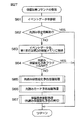
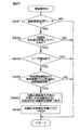
図19は、主制御基板40におけるタイマ割込処理の流れを示すフローチャートである。タイマ割込処理について、図4、図6および図19を参照しつつ説明する。
タイマ割込処理が開始されると、CPU40Aのレジスタを保存することなく、速やかに異常電源チェック処理が実行される(ステップS1)。異常電源チェック処理では、主制御基板40に接続された電源基板53から主制御基板40に供給されている電圧降下信号のレベルが判定される。この電圧降下信号のレベルが電源遮断を示すレベルであることが一または複数回のタイマ割込処理に跨って検出されると、その後バックアップ処理に移行する。
FIG. 19 is a flowchart showing the flow of timer interrupt processing in the main control board 40. The timer interrupt process will be described with reference to FIG. 4, FIG. 6, and FIG.
When the timer interrupt process is started, the abnormal power supply check process is promptly executed without saving the CPU 40A register (step S1). In the abnormal power check process, the level of the voltage drop signal supplied to the main control board 40 from the power supply board 53 connected to the main control board 40 is determined. When it is detected that the level of the voltage drop signal is a level indicating power supply interruption over one or a plurality of timer interruption processes, the process proceeds to the backup process.

一方、電圧降下信号が電源遮断を示さないレベルであることが判定された場合は、遊技動作の時間を管理している各タイマについて、タイマの更新(減算)が行われる(S2:タイマ管理処理)。
次いで、入力管理処理が実行される(ステップS3)。入力管理処理は、パチンコ機1に設けられた各種センサの検出出力の内容(たとえば、各種検出センサがオンオフ信号を出力する場合にはオン状態かオフ状態か)を記憶したり、その信号に基づくデータを定期的に更新したりする処理である。各種センサとして、たとえば第1および第2特別図柄始動口入球センサ46,47、普通ゲート通過センサ48ならびに大入賞口入球センサ49等を例示することができる。
On the other hand, if it is determined that the voltage drop signal is at a level that does not indicate power-off, the timer is updated (subtracted) for each timer that manages the game operation time (S2: timer management process). ).
Next, an input management process is executed (step S3). The input management process stores the contents of detection outputs of various sensors provided in the pachinko machine 1 (for example, whether each detection sensor outputs an on / off signal, which is an on state or an off state), or based on the signals This is a process of periodically updating data. Examples of the various sensors include the first and second special symbol start entrance ball sensors 46 and 47, the normal gate passage sensor 48, and the big prize entrance ball sensor 49.

次いで、後述する普通図柄管理処理(ステップS7)における普通図柄判定で使用される当り判定用乱数カウンタ(図示しない)の値や、後述する第1および第2特別図柄管理処理(ステップS9,S10)における大当り判定用乱数判定処理で使用される大当り判定用乱数カウンタ(図示しない)の値が更新される(S4:タイマ割込内乱数管理処理)。
次いで、賞球払出装置56に遊技球を供給するための球供給機構(図示しない)に対する遊技球の補給停止の有無や遊技球の詰まりの有無を判定するエラー管理処理が行われる(ステップS5)。このエラー管理処理では、パチンコ機1内部の異常発生の有無も判定されるようになっている。
Next, the value of a random number counter for hit determination (not shown) used in normal symbol determination in normal symbol management processing (step S7) described later, and first and second special symbol management processing (steps S9, S10) described later. The value of the jackpot determination random number counter (not shown) used in the jackpot determination random number determination process in is updated (S4: random number management process in timer interruption).
Next, an error management process is performed to determine whether or not the supply of game balls to the ball supply mechanism (not shown) for supplying game balls to the prize ball payout device 56 is stopped and whether or not the game balls are clogged (step S5). . In this error management process, whether or not an abnormality has occurred in the pachinko machine 1 is also determined.

次いで、入賞口(たとえば、第1および第2特別図柄始動口26,27ならびに大入賞口30)への入球(入賞)に対し、入賞情報の確認および制御コマンドの作成を行う賞球管理処理が行われる(ステップS6)。賞球管理処理では、各入賞口26,27,30に関連して設けられた入球センサ46,47,49の検出出力が主制御基板40に入力されると、主制御基板40のCPU40Aが、これらの検出出力に基づいて、払出個数を賞球払出装置56に指示するための制御コマンドを作成する。   Next, a winning ball management process for confirming winning information and creating a control command for winning balls (winning) to winning holes (for example, the first and second special symbol start ports 26 and 27 and the big winning port 30). Is performed (step S6). In the winning ball management process, when the detection outputs of the winning ball sensors 46, 47, 49 provided in association with the winning holes 26, 27, 30 are input to the main control board 40, the CPU 40A of the main control board 40 causes the CPU 40A. Based on these detection outputs, a control command for instructing the winning ball payout device 56 of the payout number is created.

なお、このとき、主制御基板40に設けられた、大入賞口30への入賞を無効とする状態であることを表す大入賞口入賞無効フラグ(図示しない)の値が5A[H]であれば、大入賞口30の入賞による賞球払出しのための制御信号が送信されず、払出しは行われない。
次いで、普通図柄管理処理が行われる(ステップS7)。普通図柄管理処理では、電動チューリップ役物28を拡開動作させるか否かを判定する普通図柄判定処理(前述の普通図柄抽選と同等)が実行される。より詳しくはステップS4のタイマ割込内乱数管理処理によって更新された普通図柄判定用乱数カウンタ(図示しない)から取得された普通図柄判定用乱数の値を普通図柄当り数値と対比する。
At this time, if the value of the big prize winning prize invalid flag (not shown) provided on the main control board 40 is in a state of invalidating the prize winning to the big prize winning opening 30 is 5 A [H]. For example, a control signal for paying out a winning ball by winning a prize winning opening 30 is not transmitted, and no payout is performed.
Next, normal symbol management processing is performed (step S7). In the normal symbol management process, a normal symbol determination process (equivalent to the above-mentioned normal symbol lottery) for determining whether or not to expand the electric tulip accessory 28 is executed. More specifically, the value of the normal symbol determining random number obtained from the normal symbol determining random number counter (not shown) updated by the timer interrupt random number management process in step S4 is compared with the numerical value per normal symbol.

そして、電動チューリップ役物28の拡開動作が判定された場合には、電動チューリップ役物28の拡開動作に向けた処理が実行されるとともに、その後、電動チューリップ役物28の拡開動作を実現するための処理が実行される(S8:普通電動役物管理処理)。普通電動役物管理処理では、次いで、電動チューリップ役物28の拡開動作が実行される。電動チューリップ役物28の拡開動作の実行時間は減算タイマからなる普通電動役物タイマ(図示しない)によって合計時されており、この普通電動役物タイマの値が零になるまで、この拡開動作の実行が継続される。   And when the expansion operation | movement of the electric tulip accessory 28 is determined, while the process for the expansion operation of the electric tulip accessory 28 is performed, after that, the expansion operation of the electric tulip accessory 28 is performed. Processing for realizing it is executed (S8: normal electric accessory management processing). In the normal electric accessory management process, the electric tulip accessory 28 is then expanded. The execution time of the expansion operation of the electric tulip accessory 28 is totaled by a normal electric accessory timer (not shown) composed of a subtraction timer, and this expansion is continued until the value of this normal electric accessory timer becomes zero. Execution of the operation continues.

次いで、第1特別図柄管理処理が行われる(ステップS9)。この第1特別図柄管理処理では、第1特別図柄始動口26への入球に伴う一連の抽選処理が実行される。
第1特別図柄管理処理(S9)の終了後、次いで、第2特別図柄管理処理が行われる(ステップS10)。この第2特別図柄管理処理では、第2特別図柄始動口27への入球に伴う一連の抽選処理が実行される。
Next, a first special symbol management process is performed (step S9). In the first special symbol management process, a series of lottery processes associated with entering the first special symbol start opening 26 are executed.
After the end of the first special symbol management process (S9), the second special symbol management process is then performed (step S10). In the second special symbol management process, a series of lottery processes associated with entering the second special symbol start port 27 is executed.

第1特別図柄管理処理に含まれる大当り判定用乱数判定処理において大当りであると判定された場合には、その後、大入賞口30の開放動作(大入賞口開閉役物31の開閉動作)に向けた処理が実行され、その後大入賞口30の開放動作を実現するための処理が実行される(S11:特別電動役物管理処理)。
次いで、主制御基板40で管理する所定のランプ(遊技ランプ91等)に点灯動作や消灯動作を行わせるランプ管理処理が実行される(ステップS12)。
If it is determined that the jackpot determination random number determination process included in the first special symbol management process is a jackpot, then the winning winning opening 30 is opened (the opening / closing operation of the winning opening opening / closing accessory 31). After that, the process for realizing the opening operation of the special winning opening 30 is executed (S11: special electric accessory management process).
Next, a lamp management process for causing a predetermined lamp (game lamp 91 or the like) managed by the main control board 40 to perform a lighting operation or an extinguishing operation is executed (step S12).

次いで、それぞれソレノイドからなる大入賞口開閉機構52を管理するソレノイド管理処理が実行される(ステップS13)。
次いで、CPU40Aを割込み許可状態に戻した後(ステップS14)、タイマ割込処理を終える。これにより、タイマ割込処理のルーチンを脱し、無限ループのメイン処理(システムリセット処理)が実行される。このメイン処理では、電圧異常の監視とタイマ割込処理の有無の監視との確認が行われる。
Next, a solenoid management process for managing the special winning opening / closing mechanism 52 composed of solenoids is executed (step S13).
Next, after returning the CPU 40A to the interrupt enabled state (step S14), the timer interrupt process is finished. As a result, the routine of the timer interrupt process is exited, and an infinite loop main process (system reset process) is executed. In this main process, confirmation of voltage abnormality monitoring and monitoring of the presence or absence of timer interrupt processing is performed.

次いで、図19の普通図柄管理処理(S7)および普通電動役物管理処理(S8)について、図5を参照して具体的に説明する。RAM40Bには、普通図柄始動メモリ(図示しない)が設けられている。普通図柄始動メモリは、普通図柄判定用乱数を最大でたとえば5つまで記憶可能である。具体的には、普通図柄始動メモリには、普通図柄判定用乱数を記憶するための記憶領域が5つ設けられている。これらの記憶領域を、それぞれエリア0、エリア1、エリア2、エリア3、エリア4ということにする。   Next, the ordinary symbol management process (S7) and the ordinary electric accessory management process (S8) of FIG. 19 will be specifically described with reference to FIG. The RAM 40B is provided with a normal symbol start memory (not shown). The normal symbol start memory can store, for example, up to five random numbers for determining normal symbols. Specifically, the normal symbol start memory is provided with five storage areas for storing normal symbol determination random numbers. These storage areas are referred to as area 0, area 1, area 2, area 3, and area 4, respectively.

エリア1〜エリア4の4つの領域は、実行が保留されている普通図柄判定用乱数を記憶するための領域である。エリア1〜エリア4を総称する場合には、「保留データ用領域」ということにする。普通図柄ゲート34を遊技球が通過したときには、普通図柄始動メモリ内の保留データ用領域に、普通図柄判定用乱数が記憶される。具体的にはエリア1が空であればエリア1に普通図柄判定用乱数が記憶され、エリア1が空でなくエリア2が空であればエリア2に普通図柄判定用乱数が記憶され、エリア1およびエリア2が空でなくエリア3が空であればエリア3に普通図柄判定用乱数が記憶され、エリア1〜エリア3が空でなくエリア4が空であればエリア4に普通図柄判定用乱数が記憶される。エリア0は、実行対象となっている普通図柄判定用乱数を記憶するための領域である。   The four areas of area 1 to area 4 are areas for storing normal symbol determination random numbers for which execution is suspended. When the areas 1 to 4 are collectively referred to, they are referred to as “reserved data areas”. When the game ball passes through the normal symbol gate 34, a normal symbol determination random number is stored in the reserved data area in the normal symbol start memory. Specifically, if area 1 is empty, a normal symbol determination random number is stored in area 1, and if area 1 is not empty and area 2 is empty, a normal symbol determination random number is stored in area 2. If area 2 is not empty and area 3 is empty, a random number for normal symbol determination is stored in area 3, and if area 1 to area 3 is not empty and area 4 is empty, a random number for normal symbol determination in area 4 Is memorized. Area 0 is an area for storing a normal symbol determination random number to be executed.

普通図柄始動メモリ内のエリア1〜エリア4のうち、少なくともエリア1に普通図柄判定用乱数が記憶されている場合には、電動チューリップ役物28が拡開動作中でないことを条件として、エリア1〜エリア4の記憶内容が、エリア0〜エリア3にそれぞれ移行されるとともに、エリア4が空にされる。そして、エリア0に移行された普通図柄判定用乱数の判定が実行される。   If the normal symbol determination random number is stored in at least area 1 among the areas 1 to 4 in the normal symbol start memory, the area 1 is set on condition that the electric tulip accessory 28 is not being expanded. The stored contents of area 4 are transferred to area 0 to area 3, respectively, and area 4 is emptied. Then, the determination of the normal symbol determination random number transferred to area 0 is executed.

具体的には、その普通図柄判定用乱数値と普通図柄当り数値とに基づいて普通図柄抽選が実行されるとともに、その抽選結果に応じた普通図柄表示手段37の変動動作が実行される。そして、普通図柄抽選に当選すると、普通図柄表示手段37における変動動作の終了後、電動チューリップ役物28が拡開する。これにより、第2特別図柄始動口27が開放する。   Specifically, the normal symbol lottery is executed based on the random number value for normal symbol determination and the numerical value per normal symbol, and the fluctuation operation of the normal symbol display means 37 according to the lottery result is executed. When the normal symbol lottery is won, the electric tulip accessory 28 is expanded after the changing operation in the normal symbol display means 37 is completed. As a result, the second special symbol start port 27 is opened.

なお、RAM40Bの普通図柄始動メモリに対する普通図柄判定用乱数値の格納に代えて、取得した普通図柄判定用乱数値と普通図柄当り数値とに基づく普通図柄抽選の結果自体を格納するようにしてもよい。
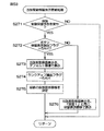
図20は、図19の第1特別図柄管理処理(S9)の流れを示すフローチャートである。第1特別図柄管理処理において、CPU40Aは、まず、第1特別図柄始動口チェック処理を行う(ステップS21)。図21は、第1特別図柄始動口チェック処理の流れを示すフローチャートである。以下、図5、図20および図21を参照しながら説明する。
Instead of storing the normal symbol determination random number value in the normal symbol start memory of the RAM 40B, the result of the normal symbol lottery based on the acquired normal symbol determination random value and the value per normal symbol may be stored. Good.
FIG. 20 is a flowchart showing the flow of the first special symbol management process (S9) of FIG. In the first special symbol management process, the CPU 40A first performs a first special symbol start port check process (step S21). FIG. 21 is a flowchart showing the flow of the first special symbol start port check process. Hereinafter, a description will be given with reference to FIGS. 5, 20, and 21.

図21において、第1特別図柄始動口チェック処理(S21)では、第1特別図柄始動口26に遊技球が入球(入賞)したか否かが判別される(ステップS31)。この判別は、第1特別図柄始動口入球センサ38の検出出力に基づいて実行される。第1特別図柄始動口26に遊技球が入球したと判別された場合には(ステップS31でYES)、第1の始動保留カウンタ63の値(第1特別図柄保留球数)が所定の保留球数上限値(第1特別図柄保留球数MAX。たとえば4)に達している否かが判別される(ステップS32)。   In FIG. 21, in the first special symbol start opening check process (S21), it is determined whether or not a game ball has entered (wins) the first special symbol start opening 26 (step S31). This determination is performed based on the detection output of the first special symbol start opening ball sensor 38. If it is determined that a game ball has entered the first special symbol start opening 26 (YES in step S31), the value of the first start hold counter 63 (the number of first special symbol hold balls) is a predetermined hold. It is determined whether or not the upper limit of the number of balls has been reached (first special symbol reservation number of balls MAX. For example, 4) (step S32).

第1の始動保留カウンタ63の値が保留球数上限値(特別図柄保留球数MAX)に達していない場合には(ステップS32でNO)、すなわち、第1の始動保留カウンタ63の値が3以下であれば、第1の始動保留カウンタ63の値が1だけインクリメント(+1)される(ステップS33)。
また、始動情報(乱数)が取得されて、第1の始動情報記憶部61(図示しない)内の保留データ用領域に記憶される(ステップS34)。具体的には、CPU40Aは、大当り判定用乱数カウンタ(図示しない)から大当り判定用乱数を取得するとともに、特別図柄用乱数カウンタ(図示しない)から特別図柄用乱数を取得し、大当り判定用乱数および特別図柄用乱数を第1の始動情報記憶部61内の保留データ用領域に格納する。また、CPU40Aは、第1変動パターン用乱数カウンタ(図示しない)から第1変動パターン用乱数を取得するとともに、第2変動パターン用乱数カウンタ(図示しない)から第2変動パターン用乱数を取得し、第1および第2変動パターン用乱数を、第1の始動情報記憶部61内の保留データ用領域に格納する。さらに、CPU40Aは、保留加算コマンド(B2**[H]〜B9**[H])(前述の制御コマンドの一種)を演出制御基板41に向けて送信する(ステップS35)。その後、図20のステップS22に移行する。
If the value of the first start hold counter 63 has not reached the upper limit value (the number of special design hold balls MAX) (NO in step S32), that is, the value of the first start hold counter 63 is 3. If it is below, the value of the first start hold counter 63 is incremented (+1) by 1 (step S33).
Further, start information (random number) is acquired and stored in the reserved data area in the first start information storage unit 61 (not shown) (step S34). Specifically, the CPU 40A obtains a jackpot determination random number from a jackpot determination random number counter (not shown), acquires a special symbol random number from a special symbol random counter (not shown), The special symbol random number is stored in the reserved data area in the first start information storage unit 61. Further, the CPU 40A obtains a first variation pattern random number from a first variation pattern random number counter (not shown), and obtains a second variation pattern random number from a second variation pattern random number counter (not shown), The random numbers for the first and second variation patterns are stored in the reserved data area in the first start information storage unit 61. Furthermore, the CPU 40A transmits a hold addition command (B2 ** [H] to B9 ** [H]) (a kind of the above-described control command) to the effect control board 41 (step S35). Thereafter, the process proceeds to step S22 in FIG.

なお、第1の始動情報記憶部61に対する大当り判定用乱数の格納に代えて、取得した大当り判定用乱数を予め定める大当り数値と比較判定することによる大当り抽選の結果自体を格納するようにしてもよい。
ステップS31で第1特別図柄始動口26に遊技球が入球したと判別されなかった場合(ステップS31でNO)、またはステップS32で第1の始動保留カウンタ63の値が保留球数上限値(保留球数MAX)に達していると判別された場合(ステップS32でYES)には、そのまま図20のステップS22に移行する。
Instead of storing the big hit determination random number in the first starting information storage unit 61, the big hit lottery result itself by comparing the acquired big hit determination random number with a predetermined big hit value may be stored. Good.
If it is not determined in step S31 that a game ball has entered the first special symbol start opening 26 (NO in step S31), or the value of the first start hold counter 63 is set to the hold ball number upper limit value in step S32 ( When it is determined that the number of reserved balls MAX) has been reached (YES in step S32), the process proceeds to step S22 in FIG.

図20に戻り、ステップS22では、CPU40Aは、RAM40B内に設けられた小当り中フラグの値を参照して、パチンコ機1が小当り遊技中であるか否かを調べる。   Returning to FIG. 20, in step S <b> 22, the CPU 40 </ b> A refers to the value of the small hitting / measuring flag provided in the RAM 40 </ b> B and checks whether the pachinko machine 1 is in the small hitting game.

このパチンコ機1では、小当り遊技が実行されているときには、小当り中フラグ(2バイト構成)の値がたとえば5A[H]に設定され、小当り遊技が実行されていないときには、小当り中フラグのフラグ値がたとえば00[H]に設定されているようになっている。
ステップS23では、CPU40Aは、RAM40B内に設けられた条件装置作動フラグの値を参照して、パチンコ機1が特別遊技状態の実行中であるか否かを調べる。
In this pachinko machine 1, when the small hit game is being executed, the value of the small hit / medium flag (2-byte configuration) is set to 5A [H], for example, and when the small hit game is not being executed, The flag value of the flag is set to 00 [H], for example.
In step S23, the CPU 40A refers to the value of the condition device operation flag provided in the RAM 40B and checks whether or not the pachinko machine 1 is in the special gaming state.

このパチンコ機1では、特別遊技状態が実行されているときには、条件装置作動フラグ(2バイト構成)の値がたとえば5A[H]に設定され、特別遊技状態が実行されていないときには、条件装置作動フラグのフラグ値がたとえば00[H]に設定されているようになっている。
パチンコ機1が小当り遊技の実行中または特別遊技状態の実行中である場合には(ステップS22またはS23でYES)、ステップS29に移行する。ステップS29では、第1特別図柄表示手段35の表示に用いられる第1特別図柄表示データの更新処理が実行される。そして、図19のステップS10に移行する。
In this pachinko machine 1, when the special game state is being executed, the value of the condition device operation flag (2-byte configuration) is set to 5A [H], for example, and when the special game state is not being executed, the condition device operation is being performed. The flag value of the flag is set to 00 [H], for example.
If the pachinko machine 1 is executing the small hit game or the special game state (YES in step S22 or S23), the process proceeds to step S29. In step S29, the update process of the 1st special symbol display data used for the display of the 1st special symbol display means 35 is performed. And it transfers to step S10 of FIG.

一方、パチンコ機1が小当り遊技の実行中でなく、かつ特別遊技状態の実行中でない場合には(ステップS22およびS23でNO)、第1特別図柄動作ステータスが判別される。第1特別図柄動作ステータスの値が、第1特別変動動作が停止中であることを示す値(たとえば00[H]または「01[H]」)である場合(所定の開始条件が成立)には(ステップS24でYES)、CPU40Aは第1特別図柄変動開始処理を実行する(ステップS26)。   On the other hand, when the pachinko machine 1 is not executing the small hit game and is not executing the special game state (NO in steps S22 and S23), the first special symbol operation status is determined. When the value of the first special symbol movement status is a value (for example, 00 [H] or “01 [H]”) indicating that the first special variation movement is stopped (a predetermined start condition is satisfied). (YES in step S24), the CPU 40A executes a first special symbol variation start process (step S26).

ステップS26の第1特別図柄変動開始処理では、第2の始動保留カウンタ64の値や第2特別図柄動作ステータスの値が判別され、第2の始動保留カウンタ64の値が零であり、かつ第2特別図柄動作ステータスの値が零であれば、第1の始動保留カウンタ63の値が零であるか否かが判別される。第1の始動保留カウンタ63の値が零である場合には、第1特別図柄動作ステータスの値が00[H]に設定されている。そして、第1特別図柄表示データの更新処理(S29)が行なわれた後、図19のステップS10に移行する。   In the first special symbol variation start process of step S26, the value of the second start hold counter 64 and the value of the second special symbol operation status are determined, the value of the second start hold counter 64 is zero, and If the value of the 2 special symbol operation status is zero, it is determined whether or not the value of the first start hold counter 63 is zero. When the value of the first start hold counter 63 is zero, the value of the first special symbol operation status is set to 00 [H]. And after the update process (S29) of 1st special symbol display data is performed, it transfers to step S10 of FIG.

第1の始動保留カウンタ63の値が零でないとき(1以上のとき)には、第1特別図柄の変動動作を開始させるための処理が実行される。すなわち、第1の始動保留カウンタ63の値が1だけデクリメント(-1)されるとともに、第1の始動情報記憶部61内の保留データ用領域(エリア1〜エリア4)の内容が、それぞれエリア0〜エリア3に移行される。これにより、第1の始動情報記憶部61内のエリア1に記憶されていた始動情報が実行データ用領域(エリア0)に記憶される。その後、第1の始動情報記憶部61内のエリア4の内容が空にされる。   When the value of the first start hold counter 63 is not zero (1 or more), a process for starting the changing operation of the first special symbol is executed. In other words, the value of the first start hold counter 63 is decremented by 1 (-1), and the contents of the hold data area (area 1 to area 4) in the first start information storage unit 61 are the areas. Moves from 0 to area 3. As a result, the start information stored in the area 1 in the first start information storage unit 61 is stored in the execution data area (area 0). Thereafter, the contents of the area 4 in the first start information storage unit 61 are emptied.

そして、第1の始動情報記憶部61内の実行データ用領域に記憶された始動情報に含まれる大当り判定用乱数の値と大当り数値とが比較されることにより、特別遊技状態が実行される大当りか否かが判定される(大当り判定)。   Then, the big hit determination random number value included in the start information stored in the execution data area in the first start information storage unit 61 is compared with the big hit value, so that the special hit state is executed. It is determined whether or not (big hit determination).

そして、第1の始動情報記憶部61内の実行データ用領域に記憶された始動情報に含まれる大当り判定用乱数の値と大当り数値とが比較されることにより、特別遊技状態が実行される大当りか否かが判定される(大当り判定)。
大当り判定が行なわれた場合には、大当り判定の結果および始動情報に含まれる第1特別図柄用乱数の値に基づいて、第1特別変動動作の後に第1特別図柄表示手段35に停止表示すべき第1特別図柄が決定される。また、大当り判定の結果ならびに始動情報に含まれる第1および第2変動パターン用乱数の値に基づいて、液晶表示ユニット24における演出図柄の変動動作の態様である変動パターンが決定される。主制御基板40において決定された変動パターンは、変動パターンコマンド(A0**[H])を介して演出制御基板41に付与される。演出制御基板41は、変動パターンコマンド(A0**[H])のイベントデータから変動パターンを読み出し、具体的な変動内容を決定する。その後、液晶表示ユニット24において、演出図柄の変動動作が開始される。
Then, the big hit determination random number value included in the start information stored in the execution data area in the first start information storage unit 61 is compared with the big hit value, so that the special hit state is executed. It is determined whether or not (big hit determination).
When the big hit determination is performed, the first special symbol display means 35 is stopped and displayed after the first special variation operation based on the result of the big hit determination and the value of the first special symbol random number included in the start information. The first special symbol to be determined is determined. Further, based on the result of the jackpot determination and the first and second variation pattern random numbers included in the start information, a variation pattern which is an aspect of the variation operation of the effect symbol in the liquid crystal display unit 24 is determined. The variation pattern determined on the main control board 40 is given to the effect control board 41 via a variation pattern command (A0 ** [H]). The effect control board 41 reads the variation pattern from the event data of the variation pattern command (A0 ** [H]), and determines specific variation contents. Thereafter, in the liquid crystal display unit 24, the changing operation of the effect symbol is started.

さらに、第1特別図柄の変動時間等を計時するための第1特別図柄動作タイマ(図示しない)に変動時間がセットされる。第1特別図柄動作タイマは、減算型のタイマである。また、第1特別図柄動作ステータスの値が、第1特別変動動作が開始されたことを示す値(たとえば「02[H]」に設定される。第1特別図柄変動開始処理が終了すると、ステップS29に移行し、第1特別図柄表示データの更新処理が実行される。そして、図19のステップS3に移行する。   Further, the variation time is set in a first special symbol operation timer (not shown) for measuring the variation time of the first special symbol. The first special symbol operation timer is a subtraction type timer. In addition, the value of the first special symbol movement status is set to a value (for example, “02 [H]”) indicating that the first special fluctuation movement has been started. The process proceeds to S29, the first special symbol display data update process is executed, and the process proceeds to Step S3 in FIG.

ステップS24において、第1特別図柄動作ステータスの値が、第1特別変動動作が停止中であることを示す値(たとえば00[H]または「01[H]」)でないと判別された場合には(ステップS24でNO)、第1特別図柄動作ステータスの値が、第1特別変動動作が開始されたことを示す値(たとえば「02[H]」)であるか否かが判別される(ステップS25)。   If it is determined in step S24 that the value of the first special symbol movement status is not a value indicating that the first special variation movement is stopped (for example, 00 [H] or “01 [H]”). (NO in step S24), it is determined whether or not the value of the first special symbol movement status is a value (for example, “02 [H]”) indicating that the first special variation movement is started (step 02). S25).

第1特別図柄動作ステータスの値が、第1特別図柄の変動動作が開始されたことを示す値(たとえば「02[H]」)であると判別された場合には(ステップS25でYES)、CPU40Aは第1特別図柄変動中処理を実行する(ステップS27)。
第1特別図柄変動中処理においては、第1特別図柄動作タイマの値が零になったか否かが常に監視されている。そして、第1特別図柄動作タイマの値が零になると、第1特別変動動作を停止させる処理が実行されるともに、第1特別図柄動作タイマに所定時間(たとえば500msec)がセットされる。また、第1特別図柄動作ステータスの値が、第1特別変動動作を停止すべき状態になったことを示す値(たとえば「03[H]」)に設定される。第1特別図柄変動中処理が終了すると、ステップS29に移行し、第1特別図柄表示データの更新処理が実行される。そして、図19のステップS10に移行する。
When it is determined that the value of the first special symbol operation status is a value (for example, “02 [H]”) indicating that the variation operation of the first special symbol is started (YES in step S25), The CPU 40A executes the first special symbol changing process (step S27).
In the first special symbol changing process, it is constantly monitored whether or not the value of the first special symbol operation timer becomes zero. When the value of the first special symbol operation timer becomes zero, a process for stopping the first special variation operation is executed and a predetermined time (for example, 500 msec) is set in the first special symbol operation timer. Further, the value of the first special symbol operation status is set to a value (for example, “03 [H]”) indicating that the first special variation operation is to be stopped. When the first special symbol changing process is completed, the process proceeds to step S29, and the first special symbol display data update process is executed. And it transfers to step S10 of FIG.

ステップS25において、第1特別図柄動作ステータスの値が、第1特別変動動作が開始されたことを示す値(たとえば「02[H]」)でないと判別された場合には(ステップS25でNO)、CPU40Aは、第1特別図柄動作ステータスの値が、第1特別図柄変動中処理において第1特別変動動作を停止すべき状態になったことを示す値(たとえば「03[H]」)であると判断し、第1特別図柄確認時間中処理を実行する(ステップS28)。   If it is determined in step S25 that the value of the first special symbol movement status is not a value indicating that the first special variation movement has started (for example, “02 [H]”) (NO in step S25). The CPU 40A indicates that the value of the first special symbol operation status is a value (for example, “03 [H]”) indicating that the first special variation operation should be stopped in the first special symbol variation processing. And the process during the first special symbol confirmation time is executed (step S28).

第1特別図柄確認時間中処理においては、第1特別図柄動作タイマの値が零になったか否かが常に監視されている。そして、第1特別図柄動作タイマの値が零になると、第1特別図柄動作ステータスの値が「01[H]」に設定される等の処理が行われる。なお、大当り判定の結果が大当りの場合には、前述した条件装置作動フラグの値が5A[H]に設定される。また、大当り判定の結果が小当りの場合には、前述した小当り中フラグの値が5A[H]に設定される。第1特別図柄確認時間中処理が終了すると、ステップS29に移行し、第1特別図柄表示データの更新処理が実行される。そして、図19のステップS10に移行する。第1特別図柄確認時間中処理において、条件装置作動フラグの値が5A[H]に設定された場合には、図19のステップS11の特別電動役物管理処理では、特別遊技状態を実現させるための処理が実行される。   In the process during the first special symbol confirmation time, it is constantly monitored whether or not the value of the first special symbol operation timer becomes zero. When the value of the first special symbol operation timer becomes zero, processing such as setting the value of the first special symbol operation status to “01 [H]” is performed. When the result of the big hit determination is a big hit, the value of the condition device operation flag described above is set to 5A [H]. Further, when the result of the big hit determination is a small hit, the value of the aforementioned small hit flag is set to 5A [H]. When the process during the first special symbol confirmation time is finished, the process proceeds to step S29, and the update process of the first special symbol display data is executed. And it transfers to step S10 of FIG. In the first special symbol confirmation time process, when the value of the condition device operation flag is set to 5A [H], in the special electric accessory management process of step S11 of FIG. 19, to realize the special gaming state. The process is executed.

図19に戻って、ステップS10に示す第2特別図柄管理処理は、次に述べる相違点を除いて、第1特別図柄管理処理(S9。図20参照)と同等の処理である。第2特別図柄管理処理では、第1特別図柄管理処理についての前述の説明において、第1特別図柄と第2特別図柄とを入れ替えた内容の処理が実行される(図20および図21に括弧書きで示す)。   Returning to FIG. 19, the second special symbol management process shown in step S10 is the same process as the first special symbol management process (S9, see FIG. 20), except for the differences described below. In the second special symbol management process, in the above description of the first special symbol management process, the process of the contents in which the first special symbol and the second special symbol are exchanged is executed (in FIG. 20 and FIG. 21 in parentheses). ).

前記の相違点は、第2特別図柄変動開始処理において、第2の始動保留カウンタ64の値が零であれば、第1の始動保留カウンタ63や第1特別図柄動作ステータスの値に拘らず、第2特別図柄動作ステータスの値が00[H]に設定されている点である。すなわち、パチンコ機1では、第2特別図柄の変動動作が、第1特別図柄の変動動作に優先して実行される。   The difference is that in the second special symbol variation start process, if the value of the second start hold counter 64 is zero, regardless of the value of the first start hold counter 63 and the first special symbol operation status, The value of the second special symbol operation status is set to 00 [H]. That is, in the pachinko machine 1, the changing operation of the second special symbol is executed with priority over the changing operation of the first special symbol.

図22は、図19の特別電動役物管理処理(S11)の流れを示すフローチャートである。図2、図5および図22を参照しつつ、特別電動役物管理処理について説明する。
特別電動役物管理処理において、まず、CPU40Aは小当り中フラグの値および条件装置作動フラグの値を参照する(ステップS41,S43)。そして、小当り中フラグの値が5A[H]である場合(ステップS41でYES)、CPU40Aは小当り遊技を実行し(ステップS42)、特別電動役物管理処理はその後リターンされる。
FIG. 22 is a flowchart showing the flow of the special electric accessory management process (S11) of FIG. The special electric accessory management process will be described with reference to FIGS. 2, 5, and 22.
In the special electric accessory management process, first, the CPU 40A refers to the value of the small hitting medium flag and the condition device operation flag (steps S41 and S43). If the value of the small hitting flag is 5A [H] (YES in step S41), the CPU 40A executes the small hit game (step S42), and the special electric accessory management process is thereafter returned.

また、小当り中フラグおよび条件装置作動フラグの値がいずれも00[H]である場合(ステップS41でNOかつステップS43でNO)、特別電動役物管理処理はそのままリターンされる。
一方、条件装置作動フラグの値が5A[H]である場合(ステップS43でYES)、特別遊技状態を実行するために、次いで、CPU40Aは、実行中の特別遊技状態の動作状況を示すための特別電動役物動作ステータス(図示しない)の値を参照する(ステップS44〜S47)。
If the values of the small hitting flag and the condition device operation flag are both 00 [H] (NO in step S41 and NO in step S43), the special electric accessory management process is directly returned.
On the other hand, when the value of the condition device operation flag is 5A [H] (YES in step S43), the CPU 40A then displays the operation status of the special game state being executed in order to execute the special game state. The value of the special electric accessory operation status (not shown) is referred to (steps S44 to S47).

特別電動役物動作ステータスは、たとえば00[H](大当り開始)、「01[H]」(特別電動役物動作開始中)、「02[H]」(特別電動役物動作中)、「03[H]」(特別電動役物動作継続判定中)および「04[H]」(大当り終了中)の値を示し、特別遊技状態の進行度合いが進むにつれて、その値が大きくなる。
特別電動役物動作ステータスの値がたとえば00[H]である場合(ステップS44でYES)、CPU40Aは、ファンファーレ等の実行等、特別遊技状態を開始するための大当り開始処理を実行する(ステップS48)。また、特別電動役物動作ステータスの値が「01[H]」であると(ステップS45でYES)、CPU40Aは、大入賞口開閉役物31の開閉動作を開始するための特別電動役物動作開始処理を実行する(ステップS49)。また、特別電動役物動作ステータスの値が「02[H]」であると(ステップS46でYES)、CPU40Aは、大入賞口開閉役物31の開閉動作を実行するための特別電動役物動作中処理を実行する(ステップS50)。また、特別電動役物動作ステータスの値がたとえば「03[H]」であると(ステップS47でYES)、CPU40Aは、大入賞口開閉役物31の開閉動作を継続するか否か(次のラウンドに移行するか否か)の特別電動役物動作継続判定処理を実行する(ステップS51)。また、特別電動役物動作ステータスの値がたとえば「04[H]」である場合(ステップS47でNO)、CPU40Aは、特別遊技状態を終了するための大当り終了処理を実行する(ステップS52)。ステップS48〜S52の各処理の後、特別電動役物管理処理はリターンされて、図19のステップS12のランプ管理処理に移行する。
For example, 00 [H] (big hit start), “01 [H]” (special electric accessory operation starts), “02 [H]” (special electric accessory operation), “ 03 [H] ”(during special electric accessory operation continuation determination) and“ 04 [H] ”(during jackpot end), and the value increases as the degree of progress of the special gaming state progresses.
When the value of the special electric accessory operation status is, for example, 00 [H] (YES in step S44), the CPU 40A executes a big hit start process for starting a special gaming state such as execution of a fanfare or the like (step S48). ). If the value of the special electric accessory operation status value is “01 [H]” (YES in step S45), the CPU 40A operates the special electric accessory operation for starting the opening / closing operation of the special winning opening opening / closing accessory 31. A start process is executed (step S49). When the value of the special electric accessory operation status is “02 [H]” (YES in step S46), the CPU 40A performs the special electric accessory operation for executing the opening / closing operation of the special prize opening opening / closing accessory 31. Medium processing is executed (step S50). If the value of the special electric accessory operation status is, for example, “03 [H]” (YES in step S47), the CPU 40A determines whether or not to continue the opening / closing operation of the prize winning opening / closing accessory 31 (next The special electric accessory operation continuation determination process is executed (whether or not to shift to a round) (step S51). On the other hand, when the value of the special electric accessory operation status is, for example, “04 [H]” (NO in step S47), the CPU 40A executes a big hit ending process for ending the special gaming state (step S52). After each process of steps S48 to S52, the special electric accessory management process is returned, and the process proceeds to the lamp management process of step S12 of FIG.

図23〜図26は、液晶表示ユニット24の表示内容の一例を示す図である。図23〜図26を参照しつつ、当該変動保留変化予告について、より具体的に説明する。
当該変動保留変化予告では、当該変動保留変化予告に関連してカード予告(第1特別演出)が実行される。この実施形態において、カード予告は、期待度示唆カードおよび/または保留態様変化カードを使用した予告であり、期待度示唆カードおよび/または保留態様変化カードが、1回または複数回連続して出現する。この実施形態では、1回のカード予告において使用されるカードの上限を3枚(すなわち1回のカード予告における予告回数は上限3回)としている。期待度示唆カードは、プレミアカード111(図33(a)参照)および期待度示唆低カード112(図33(b)参照)を含む。プレミアカード111は、大当り信頼度が極めて高う旨を告知または示唆するカードである。期待度示唆低カード112は、大当り信頼度が高いものの、プレミアカード111の大当り信頼度よりも低い旨を告知または示唆するカードである。保留態様変化カードは、図23(c)に示すランクアップ(RANK UP)カード113を含む。ランクアップカード113は、当該変動保留変化予告において当該変動保留表示104の態様変化(ランクアップ(昇格))の実行を告知するカードである。1回のカード予告において、期待度示唆カードおよび保留態様変化カードの出現枚数(回数)は、それぞれ2回を上限としている。
23 to 26 are diagrams illustrating examples of display contents of the liquid crystal display unit 24. With reference to FIGS. 23 to 26, the change hold change notice will be described more specifically.
In the change hold change notice, a card notice (first special effect) is executed in association with the change hold change notice. In this embodiment, the card notice is a notice using an expectation suggestion card and / or a hold state change card, and the expectation suggestion card and / or the hold state change card appears once or a plurality of times in succession. . In this embodiment, the upper limit of cards used in one card notice is three (that is, the number of notices in one card notice is an upper limit of three). Expectation degree suggestion cards include a premier card 111 (see FIG. 33A) and an expectation degree suggestion low card 112 (see FIG. 33B). The premier card 111 is a card that announces or suggests that the jackpot reliability is extremely high. The anticipation-indicating low card 112 is a card that notifies or suggests that although the jackpot reliability is high, it is lower than the jackpot reliability of the premium card 111. The holding mode change card includes a rank-up (RANK UP) card 113 shown in FIG. The rank-up card 113 is a card that notifies the execution of the mode change (rank up (promotion)) of the change hold display 104 in the change hold change notice. In one card notice, the number of appearances (number of times) of the expectation suggestion card and the hold mode change card is limited to two times each.

図23〜図26では、当該変動保留変化予告における当該変動保留表示104の態様変化(ランクアップ(昇格))が、演出図柄の変動動作中、ノーマルリーチ中およびスーパーリーチ中の合計3回実行される場合の演出図柄の変動動作を例に挙げて説明する。各当該変動保留変化予告の実行に先立ってカード予告が実行される。そのため、図23〜図26の例では、カード予告は、当該変動保留変化予告と同様、演出図柄の変動動作中、ノーマルリーチ中およびスーパーリーチ中の合計3回実行される。   In FIG. 23 to FIG. 26, the change in the state of the change hold display 104 (rank up (promotion)) in the change hold change notice is executed a total of three times during the change operation of the production symbol, during normal reach, and during super reach. The changing operation of the effect design in this case will be described as an example. A card notice is executed prior to the execution of each change hold notice. Therefore, in the example of FIGS. 23 to 26, the card advance notice is executed three times in total during the change operation of the production symbol, during the normal reach, and during the super reach, in the same manner as the change hold change advance notice.

全ての演出図柄の変動動作中の開始後(図23(a))、1回目のカード予告が実行される。カード予告では、カード予告の実行を予告するためのカード予告事前演出が行われる。図23(b)に示すように、カード予告事前演出は、予告内容を隠した状態の隠蔽カード114を液晶表示ユニット24に出現させる演出である。隠蔽カード114が出現してから所定時間の経過後、隠蔽カード114の内容が明かされる演出が行われる。図23(c)では、隠蔽カード114の内容は、ランクアップカード113である。ランクアップカード113の表示後、変動開始変動開始当初「白」であった当該変動保留表示104の保留表示態様が、図24(a)に示すように、たとえば「青」に変化(昇格)する。   After the start of the changing operation of all effect symbols (FIG. 23 (a)), the first card notice is executed. In the card notice, a card notice advance effect for notifying the execution of the card notice is performed. As shown in FIG. 23 (b), the card advance notice effect is an effect in which the concealment card 114 in a state in which the notice content is hidden appears on the liquid crystal display unit 24. After the elapse of a predetermined time from the appearance of the concealment card 114, an effect is presented in which the contents of the concealment card 114 are revealed. In FIG. 23C, the content of the concealment card 114 is the rank-up card 113. After the display of the rank-up card 113, the hold display mode of the change hold display 104 that was “white” at the start of change start change (elevated) to, for example, “blue” as shown in FIG. .

その後、リーチが成立し、ノーマルリーチの演出が実行される。ノーマルリーチの演出中において、図24(b)に示すように、液晶表示ユニット24に隠蔽カード114が再度出現する。隠蔽カード114が出現してから所定時間の経過後、隠蔽カード114の内容が明かされる演出が行われる。図24(c)では、隠蔽カード114の内容は、ランクアップカード113である。ランクアップカード113の表示後、それまで「青」であった当該変動保留表示104の保留表示態様が、図25(a)に示すようにたとえば「赤」に変化(昇格)する。   After that, reach is established and the effect of normal reach is executed. During the effect of normal reach, the concealment card 114 appears again on the liquid crystal display unit 24 as shown in FIG. After the elapse of a predetermined time from the appearance of the concealment card 114, an effect is presented in which the contents of the concealment card 114 are revealed. In FIG. 24C, the content of the concealment card 114 is the rank-up card 113. After display of the rank-up card 113, the hold display mode of the change hold display 104, which has been “blue” until then, is changed (promoted) to, for example, “red” as shown in FIG.

その後、ノーマルリーチの演出からスーパーリーチの演出に発展する。ノーマルリーチの演出中において、図25(b)に示すように、液晶表示ユニット24に隠蔽カード114が再度出現する。隠蔽カード114が出現してから所定時間の経過後、隠蔽カード114の内容が明かされる演出が行われる。図25(c)では、隠蔽カード114の内容は、プレミアカード111である。プレミアカード111の表示後、たとえば図26(a)に示すように、液晶表示ユニット24において極めて大当り信頼度の高いプレミア演出が実行される。   Later, it evolved from the production of normal reach to the production of super reach. During the effect of normal reach, the concealment card 114 appears again on the liquid crystal display unit 24 as shown in FIG. After the elapse of a predetermined time from the appearance of the concealment card 114, an effect is presented in which the contents of the concealment card 114 are revealed. In FIG. 25 (c), the content of the concealment card 114 is the premier card 111. After the display of the premium card 111, for example, as shown in FIG.

また、カード予告に併せて/代えて、当該変動保留変化予告に関連して先読みカード予告が行われることもある。先読みカード予告は、カード予告と同様、期待度示唆カードおよび/または保留態様変化カードを使用した予告である。先読みカード予告が、カード予告と異なる点は、カード予告の実行を予告するためのカード予告事前演出を、その演出図柄の変動開始前から開始する点である。先読みカード予告には、カードを2枚以上用いる複数カード予告(図26(b)参照)と、演出操作ボタン(たとえば第1演出操作ボタン13)の操作に応じて演出を発展させるボタン付きカード予告と、演出操作ボタン(たとえば第1演出操作ボタン13)の連続操作(連射押)に応じて演出を発展させる連打カード予告とが用意されている。   In addition to or in place of the card notice, a pre-read card notice may be performed in connection with the change hold change notice. Like the card notice, the prefetch card notice is a notice using an expectation suggestion card and / or a hold mode change card. The point that the pre-read card notice differs from the card notice is that the card notice advance effect for notifying the execution of the card notice is started before the change of the effect design starts. The pre-read card notice includes a multi-card notice using two or more cards (see FIG. 26 (b)) and a card notice with a button that develops the effect according to the operation of the effect operation button (for example, the first effect operation button 13). And a striking card notice that develops the effect in response to a continuous operation (continuous press) of the effect operation button (for example, the first effect operation button 13) is prepared.

なお、前述の説明では、当該変動保留変化予告の実行時には必ずカード予告を併せて実行させるものとして説明したが、選択的にカード予告を実行させるものであってもよい。
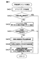
図27は、保留加算コマンド(B2**[H]〜B9**[H])の受信時における演出制御基板41の処理の流れを示すフローチャートである。図28は、図27の先読み保留変化予告抽選処理(S65)の内容を示すフローチャートである。図29は、図27の先読みカード予告抽選処理(S66)の内容を示すフローチャートである。以下、図5、図7および図27〜図29を参照しつつ説明する。
In the above description, it is described that the card notice is always executed when the change hold notice is executed, but the card notice may be selectively executed.
FIG. 27 is a flowchart showing the flow of processing of the effect control board 41 when receiving the hold addition command (B2 ** [H] to B9 ** [H]). FIG. 28 is a flowchart showing the contents of the prefetch hold change notice lottery process (S65) of FIG. FIG. 29 is a flowchart showing the contents of the pre-read card notice lottery process (S66) of FIG. Hereinafter, description will be made with reference to FIGS. 5 and 7 and FIGS.

主制御基板40からの保留加算コマンド(B2**[H]〜B9**[H])を演出制御基板41が受信すると、CPU41Aは、保留加算コマンド(B2**[H]〜B9**[H])のモードデータの値、およびイベントデータ(先読み情報)をそれぞれ参照(ステップS61)し、イベントデータの内容を確認する。
イベントデータの内容が先読み禁止情報である場合を除き(ステップS62でYES)、CPU41Aは、保留加算コマンド(B2**[H]〜B9**[H])からイベントデータを取り出し、その保留加算コマンド(B2**[H]〜B9**[H])のモードデータの値に基づいて、取り出したイベントデータを第1または第2の保留メモリ71,72に格納する(ステップS63)。イベントデータの内容が先読み禁止情報である場合には(ステップS62でYES)、図27に示す処理は、その後そのままリターンされる。
When the production control board 41 receives the hold addition command (B2 ** [H] to B9 ** [H]) from the main control board 40, the CPU 41A will hold the hold addition command (B2 ** [H] to B9 **. [H]) mode data value and event data (prefetch information) are referred to (step S61), and the contents of the event data are confirmed.
Except when the content of the event data is prefetch prohibition information (YES in step S62), the CPU 41A extracts the event data from the hold addition command (B2 ** [H] to B9 ** [H]) and adds the hold addition. Based on the mode data value of the command (B2 ** [H] to B9 ** [H]), the retrieved event data is stored in the first or second reserved memory 71, 72 (step S63). If the content of the event data is prefetch prohibition information (YES in step S62), the process shown in FIG.

具体的には、B2[H]のモードデータを有する保留加算コマンド(B2**[H]。図10参照)に含まれるイベントデータ(先読み情報)は、第1先読み記憶エリアM11に記憶される。B3[H]のモードデータを有する保留加算コマンド(B3**[H]。図10参照)に含まれるイベントデータ(先読み情報)は、第2先読み記憶エリアM12に記憶される。B4[H]のモードデータを有する保留加算コマンド(B4**[H]。図10参照)に含まれるイベントデータ(先読み情報)は、第3先読み記憶エリアM13に記憶される。B5[H]のモードデータを有する保留加算コマンド(B5 **[H]。図10参照)に含まれるイベントデータ(先読み情報)は、第4先読み記憶エリアM14に記憶される。   Specifically, event data (prefetch information) included in the pending addition command (B2 ** [H]; see FIG. 10) having mode data of B2 [H] is stored in the first prefetch storage area M11. . Event data (prefetch information) included in the pending addition command (B3 ** [H]; see FIG. 10) having mode data of B3 [H] is stored in the second prefetch storage area M12. Event data (prefetch information) included in the pending addition command (B4 ** [H]; see FIG. 10) having mode data of B4 [H] is stored in the third prefetch storage area M13. Event data (prefetch information) included in the pending addition command (B5 ** [H], see FIG. 10) having mode data of B5 [H] is stored in the fourth prefetch storage area M14.

また、具体的には、B6[H]のモードデータを有する保留加算コマンド(B6 **[H]。図11参照)に含まれるイベントデータ(先読み情報)は、第1先読み記憶エリアM21に記憶される。B7[H]のモードデータを有する保留加算コマンド(B7 **[H]。図11参照)に含まれるイベントデータ(先読み情報)は、第2先読み記憶エリアM22に記憶される。B8[H]のモードデータを有する保留加算コマンド(B8**[H]。図11参照)に含まれるイベントデータ(先読み情報)は、第3先読み記憶エリアM23に記憶される。B9[H]のモードデータを有する保留加算コマンド(B9**[H]。図11参照)に含まれるイベントデータ(先読み情報)は、第4先読み記憶エリアM24に記憶される。   More specifically, event data (prefetch information) included in a pending addition command (B6 ** [H]; see FIG. 11) having mode data of B6 [H] is stored in the first prefetch storage area M21. Is done. Event data (prefetch information) included in the pending addition command (B7 ** [H]; see FIG. 11) having the mode data of B7 [H] is stored in the second prefetch storage area M22. Event data (prefetch information) included in the pending addition command (B8 ** [H], see FIG. 11) having mode data of B8 [H] is stored in the third prefetch storage area M23. Event data (prefetch information) included in the pending addition command (B9 ** [H], see FIG. 11) having the mode data of B9 [H] is stored in the fourth prefetch storage area M24.

次いで、先読み保留変化予告フラグ76の値が調べられる(ステップS64)。先読み保留変化予告フラグ76の値が00[H]であるとき(ステップS64でNO)、すなわち先読み保留変化予告の非実行時であるときには、次いで、CPU41Aは、先読み保留変化予告抽選処理(ステップS65)および先読みカード予告抽選処理(ステップS66)をそれぞれ実行する。その後、図27に示す処理はリターンされる。一方、先読み保留変化予告フラグ76の値が5A[H]であるとき(ステップS64でYES)、図27に示す処理は、その後そのままリターンされる。   Next, the value of the prefetch hold change notice flag 76 is checked (step S64). When the value of the prefetch hold change notice flag 76 is 00 [H] (NO in step S64), that is, when the prefetch hold change notice is not executed, the CPU 41A then performs a prefetch hold change notice lottery process (step S65). ) And a pre-read card notice lottery process (step S66). Thereafter, the processing shown in FIG. 27 is returned. On the other hand, when the value of the prefetch hold change notice flag 76 is 5A [H] (YES in step S64), the process shown in FIG.

図28に示すように、ステップS65の先読み保留変化予告抽選処理では、CPU41Aは、先読み保留変化予告抽選用の抽選表T1を参照しつつ(ステップS71)、先読み保留変化予告抽選を実行する(ステップS72)。具体的には、演出制御基板41の先読み保留変化予告抽選用乱数発生部(図示しない)から取得した先読み保留変化予告抽選用乱数を、先読み保留変化予告抽選用の抽選表T1に割り当てられている先読み保留変化予告決定用数値と比較する。前述のように、先読み保留変化予告抽選用の抽選表T1では、先読み保留変化予告当選用の先読み保留変化予告抽選用乱数は、保留態様変化パターンと対応付けられており、先読み保留変化予告当選用の先読み保留変化予告決定用数値が特定されると、保留態様変化パターンが自ずと決まる。そのため、CPU41Aは、先読み保留変化予告抽選用乱数を、先読み保留変化予告抽選用の抽選表T1と比較することにより、先読み保留変化予告を実行するか否かだけでなく、先読み保留変化予告を実行する場合の保留態様変化パターンも決定する。先読み保留変化予告を実行すると決定された(先読み保留変化予告抽選に当選した)場合(ステップS73でYES)、CPU41Aは、先読み保留変化予告フラグ76の値を5A[H]に設定する(ステップS74)と共に、決定した保留態様変化パターンの種別と、この先読み保留変化予告の終了までの残りの変動回数とを、保留態様変化パターン記憶部77に記憶する(ステップS75)。その後、先読み保留変化予告抽選処理はリターンされる。
一方、先読み保留変化予告抽選に外れた場合(ステップS73でNO)、先読み保留変化予告抽選処理はそのままリターンされる。
As shown in FIG. 28, in the prefetch hold change notice lottery process in step S65, the CPU 41A executes the prefetch hold change notice lottery while referring to the prefetch hold change notice lottery table T1 (step S71). S72). Specifically, the prefetch hold change notice lottery random number acquired from the prefetch hold change notice lottery generator (not shown) of the effect control board 41 is assigned to the lottery table T1 for the prefetch hold change notice lottery. Compare with the value for determining the prefetch hold change notice. As described above, in the lottery table T1 for the prefetch hold change notice lottery, the random number for the prefetch hold change notice lottery for the prefetch hold change notice winning is associated with the hold mode change pattern, and the prefetch hold change notice lottery is selected. When the numerical value for determining the prefetch hold change notice is specified, the hold mode change pattern is automatically determined. Therefore, the CPU 41A compares the random number for the prefetch hold change notice lottery with the lottery table T1 for the prefetch hold change notice lottery to execute not only the prefetch hold change notice but also the prefetch hold change notice. A holding mode change pattern is also determined. When it is determined to execute the prefetch hold change notice (the prefetch hold change notice lottery is won) (YES in step S73), the CPU 41A sets the value of the prefetch hold notice notice flag 76 to 5A [H] (step S74). ) And the type of the determined hold mode change pattern and the remaining number of changes until the end of the prefetch hold change notice are stored in the hold mode change pattern storage unit 77 (step S75). Thereafter, the prefetch hold change notice lottery process is returned.
On the other hand, if the prefetch hold change notice lottery is off (NO in step S73), the prefetch hold change notice lottery process is returned as it is.

なお、先読み保留変化予告抽選によって決定された保留態様変化パターンを、保留態様変化パターン記憶部77に記憶するものとして説明したが、決定された保留態様変化パターンを、第1または第2の保留カウンタ73,74に記憶するようにしてもよい。
図29に示すように、先読みカード予告抽選処理では、CPU41Aは、先読みカード予告抽選用の抽選表(図示しない)を参照しつつ(ステップS81)、先読みカード予告抽選を実行する(ステップS82)。前述のように、先読みカード予告には、複数カード予告と、ボタン付きカード予告と、連打カード予告とが用意されている。具体的には、先読みカード予告抽選(S82)では、CPU41Aは、演出制御基板41の先読みカード予告抽選用乱数発生部(図示しない)から取得した先読みカード予告抽選用乱数を、先読みカード予告抽選用の抽選表(図示しない)に割り当てられている先読みカード予告決定用数値と比較することにより、先読みカード予告を実行するか否かと共に、先読みカード予告を実行する場合の先読みカード予告の種類も決定する。
Although the hold mode change pattern determined by the prefetch hold change notice lottery has been described as being stored in the hold mode change pattern storage unit 77, the determined hold mode change pattern is stored in the first or second hold counter. You may make it memorize | store in 73,74.
As shown in FIG. 29, in the pre-read card notice lottery process, the CPU 41A executes the pre-read card notice lottery while referring to a lottery table (not shown) for the pre-read card notice lottery (step S81). As described above, the pre-read card notice includes a multi-card notice, a button-equipped card notice, and a repeated card notice. Specifically, in the pre-read card notice lottery (S82), the CPU 41A uses the pre-read card notice lottery random number acquired from the pre-read card notice lottery generator (not shown) of the effect control board 41 for the pre-read card notice lottery. By comparing with the pre-read card notice determination value assigned to the lottery table (not shown), whether or not the pre-read card notice is executed and the type of the pre-read card notice when the pre-read card notice is executed are also determined. To do.

具体的には、先読みカード予告抽選(S82)において、複数カード予告に当選した場合(ステップS83でYES)には、その後に複数カード予告を実行すべく、CPU41Aは、複数カード予告実行用のフラグ(図示しない)をRAM41Bにセットする(ステップS86)。先読みカード予告抽選(S82)において、ボタン付きカード予告に当選した場合(ステップS84でYES)には、その後にボタン付きカード予告を実行すべく、CPU41Aは、ボタン付きカード予告実行用のフラグ(図示しない)をRAM41Bにセットする(ステップS86)。先読みカード予告抽選(S82)において、連打カード予告に当選した場合(ステップS85でYES)には、その後に連打カード予告を実行すべく、CPU41Aは、複数カード予告実行用のフラグ(図示しない)をRAM41Bにセットする(ステップS86)。その後、先読みカード予告抽選処理はリターンされる。   Specifically, in the pre-read card notice lottery (S82), when a plurality of card notices are won (YES in step S83), the CPU 41A sets a flag for executing a plurality of card notices in order to execute a multiple card notice thereafter. (Not shown) is set in the RAM 41B (step S86). In the pre-read card notice lottery (S82), when the card notice with button is won (YES in step S84), the CPU 41A subsequently executes a flag for executing the card notice with button (not shown). No) is set in the RAM 41B (step S86). In the pre-read card notice lottery (S82), when winning the consecutive card notice (YES in step S85), the CPU 41A sets a flag (not shown) for executing a multiple card notice to execute the repeated card notice thereafter. The RAM 41B is set (step S86). Thereafter, the pre-read card notice lottery process is returned.

図27に戻り、その後、CPU41Aは、保留数表示部101,121(図3等参照)の表示を更新する。すなわち、受信した保留加算コマンド(B2**[H]〜B9**[H])に対応する保留表示102が新たに表示される(ステップS67)。CPU41Aは、保留態様変化パターン記憶部77に記憶された保留態様変化パターンの内容に基づいて、液晶表示ユニット24の保留数表示部101,121の各保留表示102を更新表示する。たとえば、その保留加算コマンド(B2**[H]〜B9**[H])に関して決定された保留態様変化パターンの内容が、「保留1(保1)」、「保留2(保2)」、「保留3(保3)」および「保留4(保4)」が、それぞれ、「緑」、「青」、「青」および「白」である場合を例に挙げて説明すると、受信した保留増加コマンドが、保留増加によって保留数が「1」になる保留増加コマンド(B2**[H]、B6**[H])である場合、液晶表示ユニット24の保留数表示部101,121の「保留1(保1)」の保留表示位置に、保留表示102が「緑」の保留表示態様で表示される。受信した保留増加コマンドが、保留増加によって保留数が「2」になる保留増加コマンド(B3**[H]、B7**[H])である場合、液晶表示ユニット24の保留数表示部101,121の「保留2(保2)」の保留表示位置に、保留表示102が「青」の保留表示態様で表示される。受信した保留増加コマンドが、保留増加によって保留数が「3」になる保留増加コマンド(B4**[H]、B8**[H])である場合、液晶表示ユニット24の保留数表示部101,121の「保留3(保3)」の保留表示位置に、保留表示102が「青」の保留表示態様で表示される。受信した保留増加コマンドが、保留増加によって保留数が「4」になる保留増加コマンド(B5**[H]、B9**[H])である場合、液晶表示ユニット24の保留数表示部101,121の「保留4(保4)」の保留表示位置に、保留表示102が「白」の保留表示態様で表示される。   Returning to FIG. 27, thereafter, the CPU 41 </ b> A updates the display of the hold number display units 101 and 121 (see FIG. 3 and the like). That is, the hold display 102 corresponding to the received hold addition command (B2 ** [H] to B9 ** [H]) is newly displayed (step S67). The CPU 41 </ b> A updates and displays each hold display 102 of the hold number display units 101 and 121 of the liquid crystal display unit 24 based on the contents of the hold mode change pattern stored in the hold mode change pattern storage unit 77. For example, the contents of the hold mode change pattern determined for the hold addition command (B2 ** [H] to B9 ** [H]) are “hold 1 (hold 1)” and “hold 2 (hold 2)”. , “Hold 3” and “Hold 4” are “green”, “blue”, “blue” and “white” respectively. When the hold increase command is a hold increase command (B2 ** [H], B6 ** [H]) in which the hold count becomes “1” due to the hold increase, the hold count display sections 101 and 121 of the liquid crystal display unit 24. The hold display 102 is displayed in the “green” hold display mode at the hold display position of “hold 1 (hold 1)”. When the received hold increase command is a hold increase command (B3 ** [H], B7 ** [H]) in which the hold count becomes “2” due to the hold increase, the hold count display section 101 of the liquid crystal display unit 24. 121, the hold display 102 is displayed in the hold display mode of “blue” at the hold display position of “hold 2 (hold 2)”. If the received hold increase command is a hold increase command (B4 ** [H], B8 ** [H]) in which the hold count becomes “3” due to the hold increase, the hold count display section 101 of the liquid crystal display unit 24. 121, the hold display 102 is displayed in the hold display mode of “blue” at the hold display position of “hold 3 (hold 3)”. When the received hold increase command is a hold increase command (B5 ** [H], B9 ** [H]) in which the hold count becomes “4” due to the hold increase, the hold count display section 101 of the liquid crystal display unit 24. 121, the hold display 102 is displayed in the hold display mode of “white” at the hold display position of “hold 4 (hold 4)”.

図30は、変動パターンコマンド(A0**[H])の受信時における演出制御基板41の処理の流れを示すフローチャートである。図31は、当該変動保留変化予告抽選処理の流れを示すフローチャートである。図32は、カード予告抽選処理の流れを示すフローチャートである。図33は、カード予告時における、液晶表示ユニット24の表示内容の一例を示す図である。以下、図5、図7および図30〜図33を参照しつつ説明する。   FIG. 30 is a flowchart showing a flow of processing of the effect control board 41 when the variation pattern command (A0 ** [H]) is received. FIG. 31 is a flowchart showing the flow of the change hold change notice lottery process. FIG. 32 is a flowchart showing the flow of the card notice lottery process. FIG. 33 is a diagram showing an example of display contents of the liquid crystal display unit 24 at the time of card notice. Hereinafter, description will be made with reference to FIGS. 5 and 7 and FIGS.

第1または第2特別図柄の変動動作の開始タイミングになると、主制御基板40のCPU40Aは、変動パターンコマンド(A0**[H])および図柄コマンドを、演出制御基板41に送信する。変動パターンコマンド(A0**[H])を受信した演出制御基板41のCPU41Aは、変動パターンコマンド(A0**[H])のイベントデータを参照し(ステップS91)、イベントデータの内容を確認する。   At the start timing of the variation operation of the first or second special symbol, the CPU 40A of the main control board 40 transmits the variation pattern command (A0 ** [H]) and the symbol command to the effect control board 41. The CPU 41A of the effect control board 41 that has received the variation pattern command (A0 ** [H]) refers to the event data of the variation pattern command (A0 ** [H]) (step S91) and confirms the contents of the event data. To do.

次いで、CPU41Aは、当該変動保留変化予告抽選処理(ステップS92)およびカード予告抽選処理(ステップS93)をそれぞれ実行する。当該変動保留変化予告抽選処理およびカード予告抽選処理については、それぞれ後述する。
また、受信した変動パターンコマンド(A0**[H])が第1特別図柄用であるときには、CPU41Aは、第1の保留メモリ71の第1〜第4先読み記憶エリアM11〜M14(図8参照)の内容を、それぞれ、第0〜第3先読み記憶エリアM10〜M13に移行する。また、受信した変動パターンコマンド(A0**[H])が第2特別図柄用であるときには、CPU41Aは、第2の保留メモリ72の第1〜第4先読み記憶エリアM21〜M24(図8参照)の内容を、それぞれ、第0〜第3先読み記憶エリアM20〜M23に移行する(ステップS94)。
Next, the CPU 41A executes the change hold change notice lottery process (step S92) and the card notice lottery process (step S93). The variable hold change notice lottery process and the card notice lottery process will be described later.
When the received variation pattern command (A0 ** [H]) is for the first special symbol, the CPU 41A determines the first to fourth prefetch storage areas M11 to M14 of the first reserved memory 71 (see FIG. 8). ) Are transferred to the 0th to third prefetch storage areas M10 to M13, respectively. When the received variation pattern command (A0 ** [H]) is for the second special symbol, the CPU 41A causes the first to fourth prefetch storage areas M21 to M24 of the second reserved memory 72 (see FIG. 8). ) Are transferred to the 0th to third prefetch storage areas M20 to M23, respectively (step S94).

また、先読み情報の移動に併せて、対応する第1または第2の保留カウンタ73,74の値が1だけデクリメント(-1)される(ステップS95)。
次いで、CPU41Aは、保留数表示部101,121(図3等参照)の表示を更新する保留表示更新処理を実行する(ステップS96)。CPU41Aは、保留態様変化パターン記憶部77に記憶されている先読み保留変化予告用の保留態様変化パターンの内容に基づいて、液晶表示ユニット24の保留数表示部101,121の各保留表示102を更新表示する。先読み保留変化予告を実行する場合には、CPU41Aは、先読み保留変化予告の対象となる保留表示102を、決定された所定の保留表示態様(「青」、「緑」または「赤」のいずれかの保留表示態様。すなわち特別保留表示態様)で表示する。また、CPU41Aは、先読み保留変化予告のなっていない保留表示を、「白」の保留表示態様(すなわち、通常保留表示態様)で表示する。
Further, along with the movement of the prefetch information, the value of the corresponding first or second hold counter 73, 74 is decremented by 1 (-1) (step S95).
Next, the CPU 41A executes a hold display update process for updating the display of the hold number display units 101 and 121 (see FIG. 3 and the like) (step S96). The CPU 41 </ b> A updates each hold display 102 of the hold number display units 101 and 121 of the liquid crystal display unit 24 based on the content of the hold mode change pattern for prefetch hold change notice stored in the hold mode change pattern storage unit 77. indicate. When executing the pre-read hold change notice, the CPU 41A displays the hold display 102 that is the target of the pre-read hold change notice as one of the predetermined hold display modes (“blue”, “green”, or “red”). In the hold display mode, that is, the special hold display mode. Further, the CPU 41A displays a hold display that is not pre-read hold change notice in a “white” hold display mode (that is, a normal hold display mode).

次いで、CPU41Aは、当該変動保留表示部103(図3等参照)の表示を更新する保留表示更新処理を実行する(ステップS97)。CPU41Aは、保留態様変化パターン記憶部77に記憶されている、当該変動保留表示用の保留態様変化パターンの内容に基づいて、液晶表示ユニット24の当該変動保留表示部103の当該変動保留表示104を更新表示する。当該変動保留変化予告を実行する場合には、CPU41Aは、該当該変動保留表示104を、所定の一の保留表示態様(「白点滅」、「青」、「緑」、「赤」、「デンジャー」または「レインボー」のいずれかの表示態様。すなわち特別表示態様)で表示するか、あるいは複数(「白」、「白点滅」、「青」、「緑」、「赤」、「デンジャー」または「レインボー」のいずれかの保留表示態様)の間でステップアップするように表示する。当該変動保留変化予告を実行しない場合には、CPU41Aは、該当該変動保留表示104を、「白」の保留表示態様(すなわち、通常表示態様)で表示する。 Next, the CPU 41A executes a hold display update process for updating the display of the change hold display section 103 (see FIG. 3 and the like) (step S97). The CPU 41A displays the variable hold display 104 of the variable hold display unit 103 of the liquid crystal display unit 24 based on the content of the hold mode change pattern for the variable hold display stored in the hold mode change pattern storage unit 77. Update display. When the change hold change notice is executed, the CPU 41A displays the change hold display 104 in a predetermined hold display mode ("blinking white", "blue", "green", "red", "danger"). "or any of the tables示態like" Rainbow. "that should be displayed in Japanese Appendix示態like), or more (" white "," white flashing "," blue "," green "," red "," danger ”Or“ Rainbow ”on-hold display mode). If you do not execute the change pending change notice, CPU 41A is the corresponding said variation hold display 104, and displays on hold display mode of "white" (i.e., normally Table示態like).

そして、CPU41Aは、受信した変動パターンコマンド(A0**[H])および図柄コマンドに応答して、液晶表示制御基板44に制御コマンドを送信し、液晶表示ユニット24の演出図柄の変動動作を開始させる(ステップS98)。また、変動パターンが、リーチパターン等である場合には、キャラクタ等を用いた予告演出等を行う。
図31に示すように、当該変動保留変化予告抽選処理では、CPU41Aは、当該変動保留変化予告抽選用の抽選表T2〜T7のうち、変動開始当初の当該変動保留表示104の保留表示態様(色種別および点滅の有無。すなわち、保留1における保留表示102の保留表示態様)に対応する抽選表を参照しつつ(ステップS101)、当該変動保留変化予告抽選を実行する。具体的には、CPU41Aは、演出制御基板41の当該変動保留変化予告抽選用乱数発生部(図示しない)から当該変動保留変化予告抽選用乱数を取得し(ステップS102)、この当該変動保留変化予告抽選用乱数を、参照している当該変動保留変化予告抽選用の抽選表T2〜T7に割り当てられている予告決定用数値と比較する。前述のように、当該変動保留変化予告抽選用の抽選表T2〜T7では、当該変動保留変化予告当選用の当該変動保留変化予告抽選用乱数は、当該変動保留表示104の最終の保留表示態様、保留表示態様変化シナリオ(シナリオ1〜シナリオ7のいずれか)、および保留表示態様変化のタイミングのそれぞれと対応付けられている。すなわち、当該変動保留変化予告当選用の当該変動保留変化予告抽選用乱数が決まると、自ずと、当該変動保留表示104の最終の保留表示態様、保留表示態様変化シナリオ(シナリオ1〜シナリオ7のいずれか)、および保留表示態様変化のタイミングが決まる。そのため、CPU41Aは、当該変動保留変化予告抽選用乱数を、当該変動保留変化予告抽選用の抽選表T2〜T7に割り当てられている当該変動保留変化予告当選用数値と比較することにより、当該変動保留変化予告を実行するか否かだけでなく、当該変動保留表示104の最終の保留表示態様、保留表示態様変化シナリオ(シナリオ1〜シナリオ7のいずれか)、および保留表示態様変化のタイミングも決定する(ステップS103〜S105)。
Then, the CPU 41A transmits a control command to the liquid crystal display control board 44 in response to the received variation pattern command (A0 ** [H]) and the symbol command, and starts the effect symbol variation operation of the liquid crystal display unit 24. (Step S98). When the variation pattern is a reach pattern or the like, a notice effect using a character or the like is performed.
As shown in FIG. 31, in the variation hold change notice lottery process, the CPU 41 </ b> A has a hold display mode (color) of the change hold display 104 at the beginning of change among the lottery tables T <b> 2 to T <b> 7 for the change hold change notice lottery. The type and presence / absence of flashing, that is, referring to a lottery table corresponding to the hold display mode of the hold display 102 in the hold 1 (step S101), the variable hold change notice lottery is executed. Specifically, the CPU 41A obtains the variable hold change notice lottery random number from the change hold change notice lottery random number generator (not shown) of the effect control board 41 (step S102), and the change hold change notice of change. The random number for lottery is compared with the numerical value for notice determination assigned to the lottery tables T2 to T7 for the change pending change notice lottery referred to. As described above, in the lottery tables T2 to T7 for the variable hold change advance notice lottery, the random numbers for the variable hold change advance notice lottery for the variable hold change advance notice win is the final hold display mode of the change hold display 104, The hold display mode change scenario (any one of scenario 1 to scenario 7) and the hold display mode change timing are associated with each other. That is, when the variable hold change notice lottery random number for the variable hold change notice winning is determined, the final hold display form of the change hold display 104, the hold display form change scenario (scenario 1 to scenario 7) ), And the timing of the hold display mode change is determined. For this reason, the CPU 41A compares the random number for change-pending change notice lottery with the value for change-pending change notice notice lottery assigned to the lottery tables T2 to T7 for change-hold change notice lottery. Not only whether or not to execute the change notice, but also determines the final hold display mode of the variable hold display 104, the hold display mode change scenario (any one of scenario 1 to scenario 7), and the timing of the hold display mode change. (Steps S103 to S105).

そして、決定した保留変化シナリオがシナリオ4〜シナリオ7である場合(ステップS106でYES)、すなわち、保留変化を2回以上行うシナリオである場合には、CPU41Aは、当該変動保留表示104の途中の保留表示態様を決定する(ステップS107)。その後、当該変動保留変化予告抽選処理はリターンされる。一方、決定した保留変化シナリオがシナリオ1〜シナリオ3である場合(ステップS106でNO)には、当該変動保留変化予告抽選処理はリターンされる。   When the determined pending change scenario is scenario 4 to scenario 7 (YES in step S106), that is, in a scenario in which the pending change is performed twice or more, the CPU 41A displays the change pending display 104 in the middle. A hold display mode is determined (step S107). Thereafter, the variable hold change notice lottery process is returned. On the other hand, when the determined pending change scenario is scenario 1 to scenario 3 (NO in step S106), the variable pending change notice lottery process is returned.

次に、カード予告について説明する。
この実施形態では、前述のように、各当該変動先読み保留変化予告の実行に先立って、カード予告が実行される。前述のように、1回のカード予告において使用されるカードは3枚(すなわちカードによる予告は合計3枚)を上限としている。また、1回のカード予告において、期待度示唆カードおよび保留態様変化カードの出現枚数(出現回数)は、それぞれ2枚を上限として用いられる。
Next, card notice will be described.
In this embodiment, as described above, the card advance notice is executed prior to the execution of each change prefetch hold change advance notice. As described above, the maximum number of cards used in a single card notice is three (that is, a total of three notices by card). Further, in one card notice, the number of appearances (the number of appearances) of the expectation suggestion card and the hold mode change card is used with an upper limit of 2 each.

図32に示すように、カード予告抽選処理では、CPU41Aは、カード予告の実行の有無、およびカード予告の実行する場合において1回のカード予告で使用するカードの使用枚数を決定する(ステップS111)。
次いで、CPU41Aは、期待度示唆カード抽選を実行する(ステップS112)。期待度示唆カード抽選では、2枚を上限として期待度示唆カードが選ばれるが、期待度示唆カードが選ばれないこともある。つまり、この実施形態では、期待度示唆カード抽選において選ばれる期待度示唆カードの組合せとして、プレミアカード111が2枚と、期待度示唆低カード112が0枚との組合せ、プレミアカード111が1枚と、期待度示唆低カード112が1枚との組合せ、プレミアカード111が1枚と、期待度示唆低カード112が0枚との組合せ、プレミアカード111が0枚と、期待度示唆低カードが2枚との組合せ、プレミアカード111が0枚と、期待度示唆低カード112が1枚との組合せ、およびプレミアカード111が0枚と、期待度示唆低カード112が0枚との組合せを例示できる。
As shown in FIG. 32, in the card notice lottery process, the CPU 41A determines whether or not the card notice is executed and the number of cards used in one card notice when the card notice is executed (step S111). .
Next, the CPU 41A executes an expectation suggestion card lottery (step S112). In the expectation suggestion card lottery, an expectation suggestion card is selected with an upper limit of two, but the expectation suggestion card may not be selected. That is, in this embodiment, as a combination of expectation suggestion cards selected in the expectation suggestion card lottery, a combination of two Premier cards 111, zero expectation suggestion low cards 112, and one Premier card 111 is used. And a combination of 1 anticipation low card 112, 1 premium card 111, 0 anticipation low card 112, 0 premier card 111, 0 anticipation low card Example of a combination of 2 cards, a combination of 0 premium cards 111 and a low expectation-indicating low card 112, and a combination of 0 premium cards 111 and a low expectation-indicating low card 112 it can.

次いで、CPU41Aは、保留態様変化カード抽選を実行する(ステップS113)。保留態様変化カード抽選では、2枚を上限として保留態様変化カードが選ばれるが、保留態様変化カードが選ばれないこともある。つまり、この実施形態では、保留態様変化カード抽選において選ばれる保留態様変化カードの組合せとして、ランクアップカード113が2枚、ランクアップカード113が1枚、およびランクアップカード113が0枚を例示できる。   Next, the CPU 41A executes a hold mode change card lottery (step S113). In the hold mode change card lottery, the hold mode change card is selected up to two cards, but the hold mode change card may not be selected. That is, in this embodiment, two rank-up cards 113, one rank-up card 113, and zero rank-up cards 113 can be exemplified as combinations of the hold mode change cards selected in the hold mode change card lottery. .

ステップS112の期待度示唆カード抽選で決定された期待度示唆カードの枚数と、ステップS113の保留態様変化カード抽選で決定された保留態様変化カードの枚数との合計枚数が、ステップS111の抽選で決定されたカードの使用枚数を下回る場合には(ステップS114でYES)、CPU41Aは、ステップS111の抽選で決定されたカードの使用枚数と等しくなるかあるいは当該使用枚数を上回るまで、ステップS112の期待度示唆カード抽選およびステップS113の保留態様変化カード抽選を繰り返して実行する(ステップS112〜S114)。   The total number of expectation suggestion cards determined in the expectation suggestion card lottery in step S112 and the number of hold state change cards determined in the hold state change card lottery in step S113 is determined in the lottery in step S111. If it is less than the number of cards used (YES in step S114), CPU 41A expects step S112 until it equals or exceeds the number of cards used determined in the lottery of step S111. The suggestion card lottery and the hold mode change card lottery in step S113 are repeatedly executed (steps S112 to S114).

そして、決定された期待度示唆カードの枚数と保留態様変化カードの枚数との合計枚数が、ステップS111の抽選で決定されたカードの使用枚数と等しい場合には(ステップS114でNO、かつステップS115でYES)、次いで、カード予告におけるカードの表示順序が決定される(ステップS116)。決定された期待度示唆カードの枚数と保留態様変化カードの枚数との合計枚数が、ステップS111の抽選で決定されたカードの使用枚数を上回る場合(ステップS114およびステップS115でNO)には、そのカード予告における期待度示唆カードおよび保留態様変化カードの優先度に応じて、期待度示唆カードの枚数、および保留態様変化カードの枚数がそれぞれ決定され(ステップS118,ステップS119)。具体的には、カード予告において期待度示唆カードの優先度が保留態様変化カードよりも高い場合には、期待度示唆カードが優先して選択される(ステップS118)。一方、カード予告において保留態様変化カードの優先度が期待度示唆カードよりも高い場合には、保留態様変化カードが優先して選択される(ステップS118,ステップS119)。   If the total number of the determined expectation-indicating cards and the number of holding mode change cards is equal to the number of cards used determined in the lottery in step S111 (NO in step S114, and step S115). Next, the display order of the cards in the card notice is determined (step S116). In the case where the total number of the determined number of expected level suggestion cards and the number of holding mode change cards exceeds the number of cards used determined in the lottery of step S111 (NO in step S114 and step S115), The number of anticipation suggestion cards and the number of reservation mode change cards are respectively determined in accordance with the priority of the anticipation suggestion card and the hold mode change card in the card notice (steps S118 and S119). Specifically, when the priority of the expectation suggestion card is higher than the hold mode change card in the card notice, the expectation suggestion card is preferentially selected (step S118). On the other hand, when the priority of the hold mode change card is higher than the expectation suggestion card in the card notice, the hold mode change card is selected with priority (step S118, step S119).

カード予告におけるカードの表示順序の決定(S116,S118,S119)は、当該変動保留変化予告の最終の保留表示態様、および/または大当りであるか否か等に基づいて決定される。
図33では、期待度示唆カードの枚数が1枚で保留態様変化カードの枚数が2枚である場合(S119)における、カードの表示順序を示している。なお、選択される保留態様変化カードが2枚である場合には、ランクアップ回数が2回以上の当該変動保留変化予告が実行される場合に限られる。
The display order of the cards in the card notice (S116, S118, S119) is determined based on the final hold display mode of the change hold change notice and / or whether it is a big hit or the like.
FIG. 33 shows the card display order when the number of cards indicating the degree of expectation is one and the number of holding mode change cards is two (S119). Note that when the number of hold mode change cards to be selected is two, it is limited to the case where the variable hold change notice with a rank increase count of 2 or more is executed.

この場合、たとえば、当該変動保留変化予告の最終の保留表示態様が「赤」以上(「赤」、「デンジャー」または「レインボー」)である場合には、期待度示唆カードとしてプレミアカード111が用いられる。プレミアカード111を用いるとき、その表示タイミングを最後にすると効果的である。たとえば、図33(a)に示すように、ランクアップカード113→ランクアップカード113→プレミアカード111の順で表示される。   In this case, for example, when the final hold display mode of the change hold change notice is “red” or more (“red”, “danger” or “rainbow”), the premier card 111 is used as an expectation suggestion card. It is done. When using the premier card 111, it is effective to make the display timing last. For example, as shown in FIG. 33A, the rank-up card 113, the rank-up card 113, and the premium card 111 are displayed in this order.

また、当該変動保留変化予告の最終の保留表示態様の大当り信頼度が「緑」以下(「白」、「白点滅」、「青」または「緑」)である場合には、期待度示唆カードとして期待度示唆低カード112が用いられる。期待度示唆低カード112を用いるとき、その表示タイミングを最後にすると効果的である。たとえば、図33(a)に示すように、このとき、図33(a)に示すように、期待度示唆低カード112→ランクアップカード113→ランクアップカード113の順で表示される。   In addition, when the jackpot reliability of the final hold display mode of the variable hold change notice is “green” or less (“white”, “white blinking”, “blue”, or “green”), the expectation suggestion card As shown in FIG. When the anticipation suggestion low card 112 is used, it is effective to make the display timing last. For example, as shown in FIG. 33 (a), at this time, as shown in FIG. 33 (a), the expected degree suggestion low card 112 → rank up card 113 → rank up card 113 are displayed in this order.

以上により、この第1実施形態によれば、先読み保留変化予告は、始動情報に対応する変動パターンの種別がリーチパターンであるか否かに拘らず実行可能である一方、当該変動保留変化予告は、対応する変動パターンの種別がリーチパターンである場合に限り実行可能である。そのため、先読み保留変化予告の後には、リーチ演出が実行されることもあればリーチ演出が実行されないこともあるが、当該変動保留変化予告の後には、必ずリーチ演出が実行される。これにより、先読み保留変化予告および当該変動保留変化予告による演出効果の向上を図ることができ、ゆえに、遊技の興趣を高めることができるパチンコ機1を提供できる。   As described above, according to the first embodiment, the prefetch hold change notice can be executed regardless of whether or not the type of the change pattern corresponding to the start information is the reach pattern, while the change hold change notice is It can be executed only when the type of the corresponding variation pattern is a reach pattern. Therefore, a reach effect may be executed or a reach effect may not be executed after the prefetch hold change notice, but a reach effect is always executed after the change hold change notice. Thereby, the pachinko machine 1 which can aim at the improvement of the presentation effect by the pre-reading hold change notice and the said change hold change notice, and can raise the interest of a game can be provided.

次に、パチンコ機1の第1の変形例について説明する。第1の変形例において前述の内容と相違する点は、演出制御基板41の抽選表記憶部75(図6参照)に、先読み保留変化予告用の抽選表T11、当該変動保留変化予告用の抽選表T12,T13が記憶されている点である。なお、以下の説明では、第1の変形例を簡潔に説明すべく、当該変動保留変化予告用の抽選表として、変動開始当初の当該変動保留表示104の保留表示態様が「緑」である場合の抽選表T12と、変動開始当初の当該変動保留表示104の保留表示態様が「緑」である場合の抽選表T13を例に挙げて説明するが、むろん、変動開始当初の当該変動保留表示104が他の保留表示態様である場合の抽選表も用意されている。   Next, a first modification of the pachinko machine 1 will be described. The first modified example is different from the above-described content in that the lottery table storage unit 75 (see FIG. 6) of the effect control board 41 stores the lottery table T11 for the prefetch hold change notice, the lottery for the change hold notice of change. Tables T12 and T13 are stored. In the following description, in order to briefly explain the first modification, when the change hold display 104 of the change hold display 104 at the beginning of change is “green” as the change hold change notice lottery table. The lottery table T12 and the lottery table T13 when the hold display mode of the change hold display 104 at the beginning of change is “green” will be described as an example. There is also a lottery table in the case where is in another hold display mode.

図34A〜図34Dには、説明の簡略化を図るべく、ハズレのスぺシャルリーチ1の変動パターン、ハズレのスぺシャルリーチ2の変動パターン、16ラウンド大当りのスぺシャルリーチ1の変動パターンおよび16ラウンド大当りのスぺシャルリーチ2の変動パターンに対応する抽選表T11,T12,T13のみを図示し、その他の変動パターンに対応する抽選表の図示を省略している。   In FIGS. 34A to 34D, for the sake of simplification of explanation, the variation pattern of the lost special reach 1, the variation pattern of the lost special reach 2, and the variation pattern of the special reach 1 per 16 round jackpots. Only the lottery tables T11, T12, and T13 corresponding to the variation pattern of the special reach 2 for the 16 round big hit are shown, and the lottery tables corresponding to the other variation patterns are not shown.

図34Aは、先読み保留変化予告用の抽選表T11の一例を示す図である。図34Aでは、第1の変形例を簡潔に説明すべく、先読み保留変化予告用の保留態様変化パターンとして合計5通りの保留態様変化パターンが用意(先読み保留変化予告が実行されない場合を含めると合計6通り)されている場合を例に挙げて説明するが、むろん、図12A〜図12Dの場合と同程度の多種多様な保留態様変化パターンが用意されていてもよい。   FIG. 34A is a diagram showing an example of a lottery table T11 for prefetch hold change notice. In FIG. 34A, in order to briefly explain the first modification, a total of five hold mode change patterns are prepared as hold mode change patterns for the prefetch hold change notice (including the case where the prefetch hold change notice is not executed) 6), of course, a variety of holding mode change patterns similar to those in FIGS. 12A to 12D may be prepared.

抽選表T11では、変動パターンの種別がハズレ用のスぺシャルリーチ1(イベントデータの値が06[H])であるときには、合計3301個の先読み保留変化予告抽選用乱数のうち、「保留1(保1)」、「保留2(保2)」、「保留3(保3)」および「保留4(保4)」が、それぞれ、「赤」、「赤」、「緑」および「緑」となる保留態様変化パターン(図34Aの右から3つ目の欄に示す保留態様変化パターン)に、901個の先読み保留変化予告抽選用乱数が割り当てられ、「赤」、「赤」、「赤」および「白」となる保留態様変化パターン(図34Aの右から2つ目の欄に示す保留態様変化パターン)に、800個の先読み保留変化予告抽選用乱数が割り当てられ、「赤」、「赤」、「赤」および「青」となる保留態様変化パターン(図34Aの一番右の欄に示す保留態様変化パターン)に、1300個の先読み保留変化予告抽選用乱数が割り当てられている。また、変動パターンの種別がハズレ用のスぺシャルリーチ2(イベントデータの値が07[H])であるときには、合計3301個の先読み保留変化予告抽選用乱数のうち、「保留1(保1)」、「保留2(保2)」、「保留3(保3)」および「保留4(保4)」が、それぞれ、「赤」、「赤」、「緑」および「緑」となる保留態様変化パターンに、820個の先読み保留変化予告抽選用乱数が割り当てられ、「赤」、「赤」、「赤」および「白」となる保留態様変化パターンに、1300個の先読み保留変化予告抽選用乱数が割り当てられ、「赤」、「赤」、「赤」および「青」となる保留態様変化パターンに901個の先読み保留変化予告抽選用乱数が割り当てられている。   In the lottery table T11, when the variation pattern type is the special reach 1 for losing (the value of the event data is 06 [H]), among the total 3301 pre-read hold change notice lottery random numbers, “hold 1 (Hold 1), hold 2 (hold 2), hold 3 (hold 3) and hold 4 (hold 4) are "red", "red", "green" and "green" respectively. 901 are assigned to the hold mode change pattern (hold mode change pattern shown in the third column from the right in FIG. 34A), 901 random numbers for prefetch hold change notice lottery are assigned, and “red”, “red”, “ Random numbers for 800 prefetch hold change notice lotteries are assigned to the hold mode change patterns (hold mode change patterns shown in the second column from the right in FIG. 34A) that are “red” and “white”. Retention pattern change pattern (“Figure”, “Red” and “Blue”) Pending form changing pattern) shown in the rightmost column of 4A, are assigned 1,300 prefetching pending change notice lottery random numbers. Further, when the type of the variation pattern is the special reach 2 for losing (the value of the event data is 07 [H]), among the total 3301 prefetch hold change notice lottery random numbers, “hold 1 (hold 1 ) ”,“ Hold 2 (Hold 2) ”,“ Hold 3 (Hold 3) ”and“ Hold 4 (Hold 4) ”become“ Red ”,“ Red ”,“ Green ”and“ Green ”respectively. 820 random numbers for pre-read hold change notice lottery are assigned to the hold form change pattern, and 1300 pre-read hold change notices are given to the hold form change patterns of “red”, “red”, “red”, and “white”. A lottery random number is assigned, and 901 prefetch hold change notice lottery random numbers are assigned to hold mode change patterns of “red”, “red”, “red”, and “blue”.

一方、変動パターンの種別が16ラウンドの大当り用のスぺシャルリーチ1(イベントデータの値が13[H])であるときには、合計3301個の先読み保留変化予告抽選用乱数のうち、「保留1(保1)」、「保留2(保2)」、「保留3(保3)」および「保留4(保4)」が、それぞれ、「緑」、「緑」、「青」および「白」となる保留態様変化パターン(図34Aの右から5つ目の欄に示す保留態様変化パターン)に、1300個の先読み保留変化予告抽選用乱数が割り当てられ、「緑」、「緑」、「青」および「青」となる保留態様変化パターン(図34Aの右から4つ目の欄に示す保留態様変化パターン)に、1800個の先読み保留変化予告抽選用乱数が割り当てられている。また、変動パターンの種別が16ラウンドの大当り用のスぺシャルリーチ2(イベントデータの値が14[H])であるときには、合計3301個の先読み保留変化予告抽選用乱数のうち、「保留1(保1)」、「保留2(保2)」、「保留3(保3)」および「保留4(保4)」が、それぞれ、「緑」、「緑」、「青」および「白」となる保留態様変化パターンに、1400個の先読み保留変化予告抽選用乱数が割り当てられ、「緑」、「緑」、「青」および「青」となる保留態様変化パターンに、1700個の先読み保留変化予告抽選用乱数が割り当てられている。   On the other hand, when the variation pattern type is special hit 1 for big hits with 16 rounds (event data value is 13 [H]), among the total 3301 prefetch hold change notice lottery random numbers, “hold 1 "Hold 1", "Hold 2", "Hold 3" and "Hold 4" are "Green", "Green", "Blue" and "White" respectively. 1300 random numbers for prefetch hold change notice lottery are assigned to the hold mode change pattern (hold mode change pattern shown in the fifth column from the right in FIG. 34A), and “green”, “green”, “ 1800 pre-read hold change notice lottery random numbers are assigned to the hold mode change patterns (hold mode change patterns shown in the fourth column from the right in FIG. 34A) of “blue” and “blue”. When the variation pattern type is special round 2 for big hit with 16 rounds (event data value is 14 [H]), among the total 3301 pre-read hold change notice lottery random numbers, “hold 1 "Hold 1", "Hold 2", "Hold 3" and "Hold 4" are "Green", "Green", "Blue" and "White" respectively. 1400 random numbers for pre-read hold change notice lottery are assigned to the hold mode change pattern, and 1700 pre-reads to the hold mode change pattern of “green”, “green”, “blue”, and “blue”. Random numbers for pending change notice lottery are assigned.

したがって、図34Aからは、16ラウンドの大当り用のスぺシャルリーチ1および2が実行される場合に、非常に高い確率で「保留1(保1)」が「緑」となる保留態様変化パターンが選択されることがわかる。また、図34Aからは、ハズレ用のスぺシャルリーチ1および2が実行される場合に、非常に高い確率で「保留1(保1)」が「赤」となる保留態様変化パターンが選択されることもわかる。   Therefore, from FIG. 34A, when 16 rounds of special reach 1 and 2 for jackpot are executed, “hold 1 (hold 1)” becomes “green” with a very high probability. It can be seen that is selected. Further, from FIG. 34A, when the special reach 1 and 2 for losing are executed, the hold mode change pattern in which “hold 1 (hold 1)” becomes “red” with a very high probability is selected. I understand that.

図34Bおよび図34Cは、変動開始当初の当該変動保留表示104の保留表示態様が「緑」である場合の、当該変動保留変化予告用の抽選表T12の一例を示す図である。図34Dは、変動開始当初の当該変動保留表示104の保留表示態様が「赤」である場合の、当該変動保留変化予告用の抽選表T13の一例を示す図である。
図34B〜図34Dでは、第1の変形例を簡潔に説明すべく、変動開始当初の当該変動保留表示104の保留表示態様が「緑」および「青」である場合の当該変動保留変化予告用の保留態様変化パターンとして、それぞれ、合計8通りの保留態様変化パターン(当該変動保留変化予告が実行されない場合を含めると合計9通り)および合計6通りの保留態様変化パターン(当該変動保留変化予告が実行されない場合を含めると合計7通り)を用意した場合を例示したが、むろん、図16A〜図16Cの場合や、図17Aおよび図17Cの場合と同程度の多種多様な保留態様変化パターンが用意されていてもよい。
FIG. 34B and FIG. 34C are diagrams showing an example of the lottery table T12 for change hold notice in advance when the hold display mode of the change hold display 104 at the beginning of change is “green”. FIG. 34D is a diagram showing an example of the lottery table T13 for change hold change notice when the hold display mode of the change hold display 104 at the beginning of change is “red”.
In FIGS. 34B to 34D, in order to briefly explain the first modification, the change hold notice for the change hold display when the hold display mode of the change hold display 104 at the beginning of the change is “green” and “blue” is used. As the holding mode change patterns, there are a total of eight holding mode change patterns (a total of nine types including the case where the variable holding change notice is not executed) and a total of six holding mode change patterns (the variable holding change notices are included). A total of 7 patterns including the case where it is not executed is shown as an example. Of course, a variety of holding mode change patterns similar to those in FIGS. 16A to 16C and FIGS. 17A and 17C are prepared. May be.

図34Bおよび図34Cに示す抽選表T12では、変動パターンの種別がハズレ用のスぺシャルリーチ1(イベントデータの値が06[H])であるとき、およびハズレ用のスぺシャルリーチ2(イベントデータの値が07[H])であるときには、3301個全ての当該変動保留変化予告抽選用乱数が、当該変動保留変化予告なしの保留態様変化パターン(ランクアップなし)に割り当てられている。   In the lottery table T12 shown in FIG. 34B and FIG. 34C, when the variation pattern type is the special reach 1 for lose (event data value is 06 [H]), and the special reach 2 for lose ( When the value of the event data is 07 [H]), all 3301 random numbers for change pending change notice lottery are assigned to the hold mode change pattern (no rank up) without the change hold change notice.

一方、図34Bおよび図34Cに示す抽選表T12では、変動パターンの種別が16ラウンドの大当り用のスぺシャルリーチ1(イベントデータの値が13[H])であるときには、合計3301個の当該変動保留変化予告抽選用乱数のうち、当該変動保留表示104の最終の保留表示態様が「赤」であり、保留表示態様変化シナリオが「シナリオ1」である保留態様変化パターン(図34Bの右から6つ目の欄に示す保留態様変化パターン)に、1600個の当該変動保留変化予告抽選用乱数が割り当てられ、当該変動保留表示104の最終の保留表示態様が「赤」であり、保留表示態様変化シナリオが「シナリオ2」である保留態様変化パターン(図34Bの右から3つ目の欄に示す保留態様変化パターン)に、1600個の当該変動保留変化予告抽選用乱数が割り当てられている。また、変動パターンの種別が16ラウンドの大当り用のスぺシャルリーチ2(イベントデータの値が14[H])であるときには、合計3301個の当該変動保留変化予告抽選用乱数のうち、当該変動保留表示104の最終の保留表示態様が「赤」であり、保留表示態様変化シナリオが「シナリオ1」である保留態様変化パターンに、1500個の当該変動保留変化予告抽選用乱数が割り当てられ、当該変動保留表示104の最終の保留表示態様が「赤」であり、保留表示態様変化シナリオが「シナリオ2」である保留態様変化パターンに、1700個の当該変動保留変化予告抽選用乱数が割り当てられている。   On the other hand, in the lottery table T12 shown in FIG. 34B and FIG. 34C, when the variation pattern type is special hit 1 for big hit with 16 rounds (the value of the event data is 13 [H]), a total of 3301 corresponding Of the random numbers for the change hold change notice lottery, the hold hold change pattern (from the right of FIG. 34B) in which the last hold display form of the change hold display 104 is “red” and the hold display form change scenario is “scenario 1”. 1600 random numbers for change hold change advance notice lottery are assigned to the hold mode change pattern shown in the sixth column), the last hold display mode of the change hold display 104 is “red”, and the hold display mode In the hold mode change pattern whose change scenario is “scenario 2” (hold mode change pattern shown in the third column from the right in FIG. 34B), 1600 of the variable hold Of notice lottery for the random number has been assigned. Further, when the variation pattern type is special hit 2 for big hit with 16 rounds (event data value is 14 [H]), among the total 3301 variation pending change notice lottery random numbers, the variation The number of random numbers for the random hold change notice lottery of 1500 is assigned to the hold mode change pattern in which the final hold display mode of the hold display 104 is “red” and the hold display mode change scenario is “scenario 1”. The random hold change lottery random number for 1700 is assigned to the hold mode change pattern in which the final hold display mode of the variable hold display 104 is “red” and the hold display mode change scenario is “scenario 2”. Yes.

また、図34Dに示す抽選表T13では、変動パターンの種別がハズレ用のスぺシャルリーチ1(イベントデータの値が06[H])であるときには、合計3301個の当該変動保留変化予告抽選用乱数のうち3201個の当該変動保留変化予告抽選用乱数が当該変動保留変化予告なしの保留態様変化パターン(ランクアップなし)に割り当てられている。また、変動パターンの種別がハズレ用のスぺシャルリーチ2(イベントデータの値が07[H])であるときには、合計3301個の当該変動保留変化予告抽選用乱数のうち3251個の当該変動保留変化予告抽選用乱数が当該変動保留変化予告なしの保留態様変化パターン(ランクアップなし)に割り当てられている。   In the lottery table T13 shown in FIG. 34D, when the variation pattern type is the special reach 1 for loss (event data value is 06 [H]), a total of 3301 variation pending change notice lotteries are used. Of the random numbers, 3201 random numbers for change hold change notice lottery are assigned to the change pattern of hold state without change notice change notice (no rank up). Further, when the variation pattern type is the special reach 2 for losing (the value of the event data is 07 [H]), 3251 of the variable hold among the total 3301 of the variable hold change notice lottery random numbers. A random number for change notice lottery is assigned to the hold mode change pattern (no rank up) without the change hold change notice.

一方、図34Dに示す抽選表T13では、変動パターンの種別が16ラウンドの大当り用のスぺシャルリーチ1(イベントデータの値が13[H])であるとき、および変動パターンの種別が16ラウンドの大当り用のスぺシャルリーチ2(イベントデータの値が14[H])であるときには、合計3301個の当該変動保留変化予告抽選用乱数のいずれも、当該変動保留変化予告なしの保留態様変化パターン(ランクアップなし)には割り当てられていない。   On the other hand, in the lottery table T13 shown in FIG. 34D, when the variation pattern type is special hit 1 for big hits with 16 rounds (event data value is 13 [H]), and the variation pattern type is 16 rounds. Is the special reach 2 for big hits (the value of the event data is 14 [H]), all of the random numbers for the variable hold change notice lottery of 3301 in total hold state change without the change hold change notice Not assigned to a pattern (no rank up).

したがって、図34B〜図34Dからは、当該変動保留表示104の変動開始当初の態様が「緑」であるときに16ラウンドの大当り用のスぺシャルリーチ1および2が実行される場合に、非常に高い確率で、最終の保留表示態様が「赤」となる保留態様変化パターンが選択されることがわかる。また、変動開始当初の当該変動保留表示104の保留表示態様が「緑」であるときにハズレ用のスぺシャルリーチ1および2が実行される場合に、最終の保留表示態様が「赤」となる保留態様変化パターンは選択されないこともわかる。さらに、変動開始当初の当該変動保留表示104の保留表示態様が「赤」であるときに、16ラウンドの大当り用のスぺシャルリーチ1および2が実行される場合、当該変動保留変化予告なしの保留態様変化パターン(ランクアップなし)は選択されないこともわかる。   Therefore, from FIG. 34B to FIG. 34D, when the special reach 1 and 2 for 16 rounds of big hit are executed when the initial state of the change on the change hold display 104 is “green”, It can be seen that the hold mode change pattern with the final hold display mode of “red” is selected with a high probability. Further, when the special reach 1 and 2 for losing is executed when the hold display mode of the change hold display 104 at the beginning of the change is “green”, the final hold display mode is “red”. It can also be seen that the hold mode change pattern is not selected. Further, when the special reach 1 and 2 for 16 rounds of big hit are executed when the hold display mode of the change hold display 104 at the beginning of the change is “red”, the change hold change notice is not given. It can also be seen that the hold mode change pattern (no rank up) is not selected.

以上により、先読み保留変化予告による態様変化で保留表示102の保留表示態様が「緑」まで達すると共に、その後の当該変動保留変化予告における態様変化(ランクアップ)で当該変動保留表示104の保留表示態様が最終的に「赤」(第1特別保留態様)まで到達する場合の大当り信頼度はほぼ100%である。また、先読み保留変化予告による態様変化で保留表示102の保留表示態様が「赤」まで達し、その後の当該変動保留変化予告で態様変化(ランクアップ)しない場合の大当り信頼度はほぼ0%である。すなわち、第1の変形例では、当該変動保留変化予告で態様変化(ランクアップ)を経由して当該変動保留表示104の最終の保留表示態様が「赤」になる場合の大当り信頼度は、当該変動保留変化予告で態様変化を経由せずに当該変動保留表示104の最終の保留表示態様が「赤」になる場合と比較して高くなるような制御が行われる、といえる。   As described above, the hold display mode of the hold display 102 reaches “green” due to the mode change due to the prefetch hold change notice, and the hold display mode of the change hold display 104 after the mode change (ranking up) in the subsequent change hold change notice. Is finally 100%, the jackpot reliability when it reaches “red” (first special hold mode). In addition, when the hold display mode of the hold display 102 reaches “red” due to the mode change due to the pre-reading hold change notice, and the mode change (ranking) is not performed in the subsequent change hold notice, the big hit reliability is almost 0%. . That is, in the first modified example, the jackpot reliability when the final hold display mode of the change hold display 104 becomes “red” via the change (rank up) in the change hold change notice is It can be said that control is performed such that the final hold display mode of the change hold display 104 becomes higher than that in the case where the final hold display mode of the change hold display 104 is “red” without passing through the mode change in the change hold change notice.

以上により、第1の変形例によれば、当該変動保留変化予告において当該変動保留表示の保留表示態様が変化した結果、当該変動保留表示の最終の保留表示態様が「赤」(第1特別保留態様)になる場合の大当り信頼度が、当該変動保留変化予告において当該変動保留表示の保留表示態様が変化しないまま、当該変動保留表示の最終の保留表示態様が「赤」になる場合と比較して高い。両者において当該変動保留表示104の最終の保留表示態様は「赤」で共通しているが、当該変動保留表示104で態様変化する場合の方が、保留表示102のみで態様変化する場合よりも、その後に、大当り用の第1または第2特別図柄(大当り用の演出図柄)が導出される確率が高い。そのため、遊技者は、当該変動保留表示104を用いる当該変動保留変化予告に、より一層注目するようになる。したがって、演出図柄が停止表示する直前まで遊技者を遊技に引き付けておくことができる。ゆえに、遊技の興趣を高めることができるパチンコ機1を提供できる。   As described above, according to the first modification, as a result of the change of the hold display mode of the variable hold display in the change hold change notice, the final hold display mode of the variable hold display is “red” (first special hold). In comparison with the case where the final hold display mode of the variable hold display becomes “red” while the hold display mode of the variable hold display remains unchanged in the variable hold change notice, Is expensive. In both cases, the final hold display mode of the variable hold display 104 is common in “red”, but the case where the mode changes in the variable hold display 104 than the case where the mode changes only in the hold display 102. After that, there is a high probability that the first or second special symbol for jackpot (the effect symbol for jackpot) will be derived. Therefore, the player comes to pay more attention to the change hold change notice using the change hold display 104. Therefore, the player can be attracted to the game until immediately before the effect symbol is stopped and displayed. Therefore, the pachinko machine 1 that can enhance the interest of the game can be provided.

次に、パチンコ機1の第2の変形例について説明する。第2の変形例が、図1〜図33の内容と相違する点は、演出制御基板41の抽選表記憶部75(図6参照)に、先読み保留変化予告用の抽選表T21、当該変動保留変化予告用の抽選表T22,T23が記憶されている点である。なお、以下の説明では、第2の変形例を簡潔に説明すべく、当該変動保留変化予告用の抽選表として、変動開始当初の当該変動保留表示104の保留表示態様が「緑」である場合の抽選表T22と、変動開始当初の当該変動保留表示104の保留表示態様が「白点滅」である場合の抽選表T23を例に挙げて説明するが、むろん、変動開始当初の当該変動保留表示104が他の保留表示態様である場合の抽選表も用意されている。   Next, a second modification of the pachinko machine 1 will be described. The second modification is different from the contents of FIGS. 1 to 33 in that the lottery table storage unit 75 (see FIG. 6) of the effect control board 41 has a lottery table T21 for pre-reading hold change notice, the change hold. This is a point that the lottery tables T22 and T23 for change notice are stored. In the following description, in order to briefly explain the second modification example, when the variation hold display 104 at the beginning of the variation is “green” as the variation pending change notice lottery table The lottery table T22 and the lottery table T23 when the hold display mode of the change hold display 104 at the beginning of change is “blinking white” will be described as an example. A lottery table when 104 is another hold display mode is also prepared.

また、次に述べる図35A〜図35Dには、説明の簡略化を図るべく、ハズレのスぺシャルリーチ1の変動パターン、ハズレのスぺシャルリーチ2の変動パターン、16ラウンド大当りのスぺシャルリーチ1の変動パターンおよび16ラウンド大当りのスぺシャルリーチ2の変動パターンに対応する抽選表T21,T22,T23のみを図示し、その他の変動パターンに対応する抽選表の図示を省略している。   Also, in FIGS. 35A to 35D described below, for the sake of simplification, the variation pattern of the lost special reach 1, the variation pattern of the lost special reach 2, and the special hit of 16 round big hits are shown. Only the lottery tables T21, T22, T23 corresponding to the variation pattern of the reach 1 and the variation pattern of the special reach 2 per 16 rounds are illustrated, and the lottery tables corresponding to the other variation patterns are not shown.

図35Aは、先読み保留変化予告用の抽選表T21の一例を示す図である。図35Aでは、第2の変形例を簡潔に説明すべく、先読み保留変化予告用の保留態様変化パターンとして合計5通りの保留態様変化パターンが用意(先読み保留変化予告が実行されない場合を含めると合計6通り)されている場合を例に挙げて説明するが、むろん、図12A〜図12Dの場合と同程度の多種多様な保留態様変化パターンが用意されていてもよい。   FIG. 35A is a diagram illustrating an example of a lottery table T21 for prefetch hold change notice. In FIG. 35A, in order to briefly explain the second modification, a total of five hold mode change patterns are prepared as hold mode change patterns for the prefetch hold change notice (including the case where the prefetch hold change notice is not executed) 6), of course, a variety of holding mode change patterns similar to those in FIGS. 12A to 12D may be prepared.

図35Aに示す抽選表T21では、変動パターンの種別がハズレ用のスぺシャルリーチ1(イベントデータの値が06[H])であるときには、合計3301個の先読み保留変化予告抽選用乱数のうち、「保留1(保1)」、「保留2(保2)」、「保留3(保3)」および「保留4(保4)」が、それぞれ、「緑」、「緑」、「青」および「白」となる保留態様変化パターン(図35Aの右から5つ目の欄に示す保留態様変化パターン)に、2040個の先読み保留変化予告抽選用乱数が割り当てられている。また、変動パターンの種別がハズレ用のスぺシャルリーチ2(イベントデータの値が07[H])であるときには、合計3301個の先読み保留変化予告抽選用乱数のうち、「保留1(保1)」、「保留2(保2)」、「保留3(保3)」および「保留4(保4)」が、それぞれ、「緑」、「緑」、「青」および「白」となる保留態様変化パターンに、2050個の先読み保留変化予告抽選用乱数が割り当てられている。   In the lottery table T21 shown in FIG. 35A, when the variation pattern type is special reach 1 for loss (event data value is 06 [H]), among the total of 3301 pre-reading pending change notice lottery random numbers , "Hold 1 (Hold 1)", "Hold 2 (Hold 2)", "Hold 3 (Hold 3)" and "Hold 4 (Hold 4)" are "Green", "Green", "Blue" respectively ”And“ white ”are assigned to the hold mode change patterns (hold mode change patterns shown in the fifth column from the right in FIG. 35A), and 2040 prefetch hold change notice lottery random numbers are assigned. Further, when the type of the variation pattern is the special reach 2 for losing (the value of the event data is 07 [H]), among the total 3301 prefetch hold change notice lottery random numbers, “hold 1 (hold 1 ) ”,“ Hold 2 (Hold 2) ”,“ Hold 3 (Hold 3) ”and“ Hold 4 (Hold 4) ”become“ Green ”,“ Green ”,“ Blue ”and“ White ”respectively. 2050 prefetch hold change notice lottery random numbers are assigned to the hold mode change pattern.

一方、図35Aに示す抽選表T21では、変動パターンの種別が16ラウンドの大当り用のスぺシャルリーチ1(イベントデータの値が13[H])または16ラウンドの大当り用のスぺシャルリーチ2(イベントデータの値が14[H])であるときには、合計3301個の先読み保留変化予告抽選用乱数のうち、「保留1(保1)」、「保留2(保2)」、「保留3(保3)」および「保留4(保4)」が、それぞれ、「緑」、「緑」、「青」および「白」となる保留態様変化パターンに、50個の先読み保留変化予告抽選用乱数しか割り当てられていない。   On the other hand, in the lottery table T21 shown in FIG. 35A, the special reach 1 for big hit with 16 types of variation pattern (event data value is 13 [H]) or the special reach 2 for big hit with 16 rounds. (Event data value is 14 [H]), among the total 3301 pre-read hold change notice lottery random numbers, “hold 1 (hold 1)”, “hold 2 (hold 2)”, “hold 3” (Preservation 3) "and" Reservation 4 (Preservation 4) "are for the pre-holding change notice lottery for 50 pre-orders, with the change patterns of holding status being" Green "," Green "," Blue "and" White "respectively. Only random numbers are assigned.

したがって、図35Aから、ハズレ用のスぺシャルリーチ1,2が実行される場合に、高い確率で、「保留1(保1)」が「緑」でかつ態様変化回数が2回の保留態様変化パターンが選択されることがわかる。そして、この保留態様変化パターンは、16ラウンドの大当り用のスぺシャルリーチ1,2が実行される場合には、ほとんど選択されないこともわかる。   Accordingly, from FIG. 35A, when the special reach 1 or 2 for losing is executed, with high probability, the “hold 1 (hold 1)” is “green” and the hold mode has two mode changes. It can be seen that the change pattern is selected. It can also be seen that this hold mode change pattern is hardly selected when 16 rounds of jackpot special reach 1 and 2 are executed.

図35Bおよび図35Cは、変動開始当初の当該変動保留表示104の保留表示態様が「緑」である場合の、当該変動保留変化予告用の抽選表T22の一例を示す図である。図35Dは、変動開始当初の当該変動保留表示104の保留表示態様が「白点滅」である場合の、当該変動保留変化予告用の抽選表T23の一例を示す図である。
図35B〜図35Dでは、第2の変形例を簡潔に説明すべく、変動開始当初の当該変動保留表示104の保留表示態様が「緑」および「白点滅」である場合の当該変動保留変化予告用の保留態様変化パターンとして、それぞれ、合計8通りの保留態様変化パターン(当該変動保留変化予告が実行されない場合を含めると合計9通り)および合計5通りの保留態様変化パターン(当該変動保留変化予告が実行されない場合を含めると合計6通り)を用意した場合を例示したが、むろん、図16A〜図16Cの場合や、図14A〜図14Dの場合と同程度の多種多様な保留態様変化パターンが用意されていてもよい。
FIG. 35B and FIG. 35C are diagrams showing an example of the lottery table T22 for change hold change notice when the hold display mode of the change hold display 104 at the beginning of change is “green”. FIG. 35D is a diagram showing an example of a lottery table T23 for change hold change notice when the hold display mode of the change hold display 104 at the beginning of change is “white blinking”.
In FIGS. 35B to 35D, in order to briefly explain the second modification example, the change hold notice in advance when the hold display mode of the change hold display 104 at the beginning of the change is “green” and “white blinking”. As the hold mode change patterns for use, a total of 8 hold mode change patterns (a total of 9 types including the case where the change hold change notice is not executed) and a total of 5 hold mode change patterns (the change hold change notice) 6 are included in the case of including the case where the process is not executed). Of course, there are various types of hold mode change patterns similar to those in FIGS. 16A to 16C and FIGS. 14A to 14D. It may be prepared.

図35Bおよび図35Cに示す抽選表T22では、変動パターンの種別がハズレ用のスぺシャルリーチ1(イベントデータの値が06[H])であるとき、およびハズレ用のスぺシャルリーチ2(イベントデータの値が07[H])であるときには、合計3301個の先読み保留変化予告抽選用乱数のうち2281個の当該変動保留変化予告抽選用乱数が、当該変動保留変化予告なしの保留態様変化パターン(ランクアップなし)に割り当てられている。また、当該変動保留表示104の最終の保留表示態様が「デンジャー」であり保留表示態様変化シナリオが「シナリオ4」である保留態様変化パターン(図35Bの右から2つ目の欄に示す保留態様変化パターン)にも10個の当該変動保留変化予告抽選用乱数が割り当てられているが、当該変動保留表示104の最終の保留表示態様が「レインボー」であり保留表示態様変化シナリオが「シナリオ4」である保留態様変化パターン(図35Bの一番右の欄に示す保留態様変化パターン)には当該変動保留変化予告抽選用乱数が割り当てられていない。   In the lottery table T22 shown in FIG. 35B and FIG. 35C, when the variation pattern type is the special reach 1 for loss (event data value is 06 [H]), and the special reach 2 for lose ( When the value of the event data is 07 [H]), among the total 3301 prefetch hold change notice lottery random numbers, 2281 of the change hold change notice lottery random numbers are changed in the hold mode without the change hold change notice. Assigned to a pattern (no rank up). Further, the hold mode change pattern (the hold mode shown in the second column from the right in FIG. 35B) in which the final hold display mode of the variable hold display 104 is “Danger” and the hold display mode change scenario is “Scenario 4”. Change pattern) is also assigned 10 random numbers for change pending change notice lottery, but the final hold display mode of the change hold display 104 is “Rainbow” and the hold display mode change scenario is “Scenario 4”. Is not assigned the random number for lottery change change notice lottery (the hold mode change pattern shown in the rightmost column of FIG. 35B).

一方、図35Bおよび図35Cに示す抽選表T22では、変動パターンの種別が16ラウンドの大当り用のスぺシャルリーチ1(イベントデータの値が13[H])であるとき、および16ラウンドの大当り用のスぺシャルリーチ2(イベントデータの値が14[H])であるときには、合計3301個の当該変動保留変化予告抽選用乱数のうち、当該変動保留表示104の最終の保留表示態様が「デンジャー」であり保留表示態様変化シナリオが「シナリオ4」である保留態様変化パターンに、3000個の当該変動保留変化予告抽選用乱数が割り当てられており、当該変動保留表示104の最終の保留表示態様が「レインボー」であり保留表示態様変化シナリオが「シナリオ4」である保留態様変化パターンに、200個の当該変動保留変化予告抽選用乱数が割り当てられている。   On the other hand, in the lottery table T22 shown in FIG. 35B and FIG. 35C, when the variation pattern type is special reach 1 for big hit with 16 rounds (event data value is 13 [H]), and big hit with 16 rounds Special reach 2 for the event (the value of the event data is 14 [H]), the final hold display mode of the change hold display 104 among the total 3301 change hold change notice lottery random numbers is “ 3,000 “variable hold change notice lottery random numbers are assigned to the hold mode change pattern of“ Danger ”and the hold display mode change scenario“ scenario 4 ”, and the final hold display mode of the variable hold display 104 is assigned. Is “Rainbow” and the pending display mode change scenario is “Scenario 4”. Notice lottery for the random number has been assigned.

図35Dに示す抽選表T23では、変動パターンの種別がハズレ用のスぺシャルリーチ1(イベントデータの値が06[H])であるとき、およびハズレ用のスぺシャルリーチ2(イベントデータの値が07[H])であるときには、合計3301個の当該変動保留変化予告抽選用乱数のうち20個の当該変動保留変化予告抽選用乱数が、当該変動保留表示104の最終の保留表示態様が「緑」であり保留表示態様変化シナリオが「シナリオ4」である保留態様変化パターン(図35Dの右から4つ目の欄に示す保留態様変化パターン)に割り当てられている。   In the lottery table T23 shown in FIG. 35D, the variation pattern type is the special reach 1 for loss (event data value is 06 [H]) and the special reach 2 for loss (event data When the value is 07 [H]), among the total 3301 variable hold change notice lottery random numbers, 20 variable hold change notice lottery random numbers are used as the final hold display mode of the change hold display 104. It is assigned to a hold mode change pattern (hold mode change pattern shown in the fourth column from the right in FIG. 35D) in which “green” and the hold display mode change scenario is “scenario 4”.

一方、図35Dに示す抽選表T23では、変動パターンの種別が16ラウンドの大当り用のスぺシャルリーチ1(イベントデータの値が13[H])であるとき、16ラウンドの大当り用のスぺシャルリーチ2(イベントデータの値が14[H])であるときには、合計3301個の当該変動保留変化予告抽選用乱数のうち2500個の当該変動保留変化予告抽選用乱数が、当該変動保留表示104の最終の保留表示態様が「緑」であり保留表示態様変化シナリオが「シナリオ4」である保留態様変化パターンに割り当てられている。   On the other hand, in the lottery table T23 shown in FIG. 35D, when the variation pattern type is special round 1 for big hits with 16 rounds (event data value is 13 [H]), special rounds for big rounds with 16 rounds are selected. When the reach is 2 (the value of the event data is 14 [H]), the random number for random change change notice lottery 2500 among the total 3301 random numbers for random change change notice lottery is the variable hold indication 104. Is assigned to a hold mode change pattern in which the last hold display mode is “green” and the hold display mode change scenario is “scenario 4”.

したがって、図35B〜図35Dから、変動開始当初の当該変動保留表示104の保留表示態様が「緑」であるときに16ラウンドの大当り用のスぺシャルリーチ1および2が実行される場合に、最終の保留表示態様が「デンジャー」となる「シナリオ4」の保留態様変化パターンが非常に高い確率で選択され、かつ当該変動保留変化予告なしの保留態様変化パターン(ランクアップなし)はほとんど選択されないこともわかる。   Therefore, from FIGS. 35B to 35D, when the special reach 1 and 2 for 16 rounds of big hit are executed when the hold display mode of the change hold display 104 at the beginning of the change is “green”, The hold mode change pattern of “Scenario 4” whose final hold display mode is “Danger” is selected with a very high probability, and the hold mode change pattern (without rank up) without the change hold change notice is hardly selected. I understand that.

また、図35B〜図35Dから、変動開始当初の当該変動保留表示104の保留表示態様が「緑」であるときにハズレ用のスぺシャルリーチ1および2が実行される場合に、当該変動保留変化予告なしの保留態様変化パターン(ランクアップなし)が高い確率で選択され、かつ最終の保留表示態様が「デンジャー」となる「シナリオ4」の保留態様変化パターンはほとんど選択されないこともわかる。   Also, from FIGS. 35B to 35D, when the special reach 1 and 2 for losing is executed when the hold display mode of the change hold display 104 at the beginning of change is “green”, the change hold is executed. It can also be seen that the hold mode change pattern of “scenario 4” in which the hold mode change pattern without change notice (no rank up) is selected with high probability and the final hold display mode is “Danger” is hardly selected.

さらに、図35Dから、変動開始当初の当該変動保留表示104の保留表示態様が「白点滅」であるときに16ラウンドの大当り用のスぺシャルリーチ1および2が実行される場合に、最終の保留表示態様が「緑」となる「シナリオ4」の保留態様変化パターンが高い確率で選択されること、およびハズレ用のスぺシャルリーチ1および2が実行される場合に、最終の保留表示態様が「緑」となる「シナリオ4」の保留態様変化パターンがほとんど選択されないことがわかる。   Furthermore, from FIG. 35D, when the special reach 1 and 2 for 16 rounds of big hit are executed when the hold display mode of the change hold display 104 at the beginning of the change is “blinking white”, When the hold mode change pattern of “scenario 4” in which the hold display mode is “green” is selected with high probability, and when the special reach 1 and 2 for losing are executed, the final hold display mode It can be seen that the pending state change pattern of “Scenario 4” where becomes “green” is hardly selected.

以上により「白」の保留表示102が2回の変化態様を経て「保留1(保1)」の保留表示態様が「緑」となり、その後、当該変動保留変化予告において当該変動保留表示104の保留表示態様が変化しない場合の大当り信頼度は低いことがわかる。また、図35A〜図35Dから、当該変動保留変化予告において、「白点滅」の当該変動保留表示104が2回の変化態様を経て最終的「緑」の保留表示態様となる場合の大当り信頼度は極めて高いことがわかる。また、図35A〜図35Dから、「白」の保留表示102が2回の変化態様を経て「保留1(保1)」の保留表示態様が「緑」となり、その後、当該変動保留変化予告において2回の変化態様を経て「デンジャー」や「レインボー」になるときの大当り信頼度が極めて高いこともわかる。   As described above, the hold display mode of “white” is changed to “green” after the change mode of “hold 1 (hold 1)” is changed to “green” after two change modes, and then the hold of the change hold display 104 is held in the change hold change notice. It can be seen that the big hit reliability is low when the display mode does not change. Further, from FIGS. 35A to 35D, the jackpot reliability in the case where the change hold display 104 of “blinking white” becomes the hold display form of the final “green” through the two change forms in the change hold change notice. Is extremely high. Also, from FIGS. 35A to 35D, the “white” on-hold display 102 undergoes two changes, and the on-hold display on “hold 1 (hold 1)” becomes “green”. It can also be seen that the jackpot reliability is extremely high when it becomes “Danger” or “Rainbow” after two changes.

すなわち、第2の変形例では、当該変動保留変化予告における態様変化(ランクアップ)を含む合計2回の態様変化を経由して、当該変動保留表示104の最終の保留表示態様が「緑」(所定の特別保留表示態様)になる場合の大当り信頼度が、先読み保留変化予告のみで2回の態様変化を経由して当該変動保留表示104の最終の保留表示態様が「緑」になる場合と比較して高くなるような制御が行われる、といえる。換言すれば、当該変動保留変化予告により当該変動保留表示104の保留表示態様が2回変化した場合の大当り信頼度が、先読み保留変化予告において保留表示102の保留表示態様が2回変化した場合よりも高くなるような制御が行われる、ともいえる。   In other words, in the second modified example, the final hold display mode of the change hold display 104 is “green” through a total of 2 change types including the change (rank up) in the change hold change notice. When the jackpot reliability in the case of the predetermined special hold display mode) is only the pre-read hold change notice, the final hold display mode of the variable hold display 104 becomes “green” through two mode changes. It can be said that the control is performed so as to be higher in comparison. In other words, the jackpot reliability when the hold display mode of the variable hold display 104 is changed twice by the change hold change notice is larger than when the hold display mode of the hold display 102 is changed twice in the prefetch hold change notice. It can be said that the control is performed so that the value becomes higher.

以上により、第2の変形例によれば、当該変動保留変化予告により当該変動保留表示が特定回数変化した結果当該変動保留表示の最終的な態様が「緑」になる場合の大当り信頼度が、先読み保留変化予告において保留表示が特定回数変化した結果当該変動保留表示の最終的な態様が「緑」になる場合と比較して高い。両者の間では、当該変動保留表示104の最終の保留表示態様は「緑」で共通し、また、保留表示102および/または当該変動保留表示104の合計回数も2回と共通しているが、当該変動保留表示104で態様変化する場合の方が、保留表示102のみで態様変化する場合よりも、その後に、大当り用の第1または第2特別図柄(大当り用の演出図柄)が導出される確率が高い。そのため、遊技者は、当該変動保留表示104を用いる当該変動保留変化予告に、より一層注目するようになる。したがって、演出図柄が停止表示する直前まで遊技者を遊技に引き付けておくことができる。ゆえに、遊技の興趣を高めることができるパチンコ機1を提供できる。   As described above, according to the second modified example, the jackpot reliability when the final mode of the variable hold display becomes “green” as a result of the change of the variable hold display due to the change hold change notice for a specific number of times, As a result of the change of the hold display for a specific number of times in the pre-read hold change notice, the final mode of the change hold display is higher than that in the case of “green”. Between the two, the final hold display mode of the variable hold display 104 is common in “green”, and the total number of the hold display 102 and / or the variable hold display 104 is also common to two times. The first or second special symbol for jackpot (the jackpot effect symbol) is derived after the mode change in the variable hold display 104 rather than the mode change only in the hold display 102. Probability is high. Therefore, the player comes to pay more attention to the change hold change notice using the change hold display 104. Therefore, the player can be attracted to the game until immediately before the effect symbol is stopped and displayed. Therefore, the pachinko machine 1 that can enhance the interest of the game can be provided.

また、前述の第1実施形態(その第1および第2の変形例を含む。)では、当該変動保留変化予告を、通常変動中およびリーチ中(ノーマルリーチ中およびスーパーリーチ中)の一方または双方で実行するものとして説明したが、当該変動保留変化予告は、リーチ演出中(ノーマルリーチ中およびスーパーリーチ中)に実行されるものであってもよい。この場合、当該変動保留変化予告がリーチ演出中にしか出現しないので、リーチ演出に遊技者の注目を集めることができ、これにより、遊技の興趣をより一層高めることができる。   Further, in the first embodiment described above (including the first and second modifications thereof), the change hold change notice is made during one or both of normal change and reach (during normal reach and super reach). Although described as being executed, the change hold change notice may be executed during reach production (during normal reach and super reach). In this case, since the change hold change notice appears only during the reach production, the player's attention can be attracted to the reach production, thereby further enhancing the interest of the game.

なお、第2の変形例において、当該変動保留変化予告により当該変動保留表示が特定回数変化した結果当該変動保留表示の最終的な態様が「緑」になる場合の大当り信頼度が、先読み保留変化予告において保留表示が特定回数変化した結果当該変動保留表示の最終的な態様が「緑」になる場合よりも高い場合に限られず、該大当り信頼度が、先読み保留変化予告において保留表示が特定回数変化した結果当該変動保留表示の最終的な態様が「緑」になる場合と異なっていればよい。   In the second modification, the jackpot reliability when the final state of the variable hold display changes to “green” as a result of the change of the variable hold display by a specific number of times due to the change hold change notice is the prefetch hold change. As a result of the change of the hold display in the advance notice, it is not limited to the case where the final form of the change hold display is “green”. What is necessary is just to differ from the case where the final mode of the change hold display becomes “green” as a result of the change.

図13A〜図13D、図34B〜図34Dおよび図35B〜図35Dにそれぞれ示す当該変動保留変化予告用の抽選表T2〜T7,T12,T13,T22,T23から、1回目の変動動作中を保留表示態様変化のタイミングに規定しているシナリオ1、シナリオ4、シナリオ5およびシナリオ7を含む保留態様変化パターンを除くことにより、当該変動保留変化予告をリーチ中(ノーマルリーチ中およびスーパーリーチ中)にのみ実行可能な構成を実現できる。   From the lottery tables T2 to T7, T12, T13, T22, T23 for the change hold change notice shown in FIGS. 13A to 13D, 34B to 34D, and 35B to 35D, hold during the first change operation. By excluding the hold mode change pattern including scenario 1, scenario 4, scenario 5 and scenario 7 defined in the timing of display mode change, the variable hold change notice is only in reach (during normal reach and super reach) An executable configuration can be realized.

図36は、本発明の第2実施形態に係る演出制御基板41の電気的構成を示すブロック図である。図37は、本発明の第2実施形態に係る、先読み保留変化予告の保留態様変化パターンの一例を示す図である。
第2実施形態に係るパチンコ機201の説明において、第1実施形態に係るパチンコ機1と共通する部分には、図1〜図35Bの場合と同一の参照符号を付して、説明を省略する。パチンコ機201の機械的、電気的構成および基本的な制御内容は、それぞれパチンコ機1と同等である。また、以下で特に言及する場合する場合を除き、リーチ演出等の演出も、第1実施形態の場合と同様である。以下では、主に、パチンコ機201がパチンコ機1と相違する部分について説明する。
FIG. 36 is a block diagram showing an electrical configuration of the effect control board 41 according to the second embodiment of the present invention. FIG. 37 is a diagram showing an example of a hold mode change pattern of a prefetch hold change notice according to the second embodiment of the present invention.
In the description of the pachinko machine 201 according to the second embodiment, parts common to the pachinko machine 1 according to the first embodiment are denoted by the same reference numerals as in FIGS. . The mechanical and electrical configuration and basic control contents of the pachinko machine 201 are the same as those of the pachinko machine 1. In addition, unless otherwise noted below, effects such as reach effects are the same as in the first embodiment. Below, the part from which the pachinko machine 201 differs from the pachinko machine 1 is mainly demonstrated.

図36に示すように、演出制御基板41のROM41Cは、抽選表記憶部275と、保留態様変化パターン記憶部278とを含む。抽選表記憶部275は、先読み保留変化予告用の抽選表や当該変動保留変化予告用の抽選表を含む種々の抽選表(抽選テーブル)を記憶している。抽選表記憶部275に記憶される抽選表は、たとえば、第1実施形態に係る抽選表T1〜T23と同等の抽選表を含む。保留態様変化パターン記憶部278は、先読み保留変化予告の保留態様変化パターンを記憶する。保留態様変化パターン記憶部278に記憶される保留態様変化パターンの一例として、図37に示すような保留態様変化パターンPDを挙げることができる。   As shown in FIG. 36, the ROM 41 </ b> C of the effect control board 41 includes a lottery table storage unit 275 and a hold mode change pattern storage unit 278. The lottery table storage unit 275 stores various lottery tables (lottery tables) including a lottery table for prefetch hold change notice and a lottery table for change hold notice of change. The lottery table stored in the lottery table storage unit 275 includes, for example, a lottery table equivalent to the lottery tables T1 to T23 according to the first embodiment. The hold mode change pattern storage unit 278 stores the hold mode change pattern of the prefetch hold change notice. As an example of the hold mode change pattern stored in the hold mode change pattern storage unit 278, a hold mode change pattern PD as shown in FIG. 37 can be cited.

図36に示すように、演出制御基板41のRAM41Bには、第1の保留メモリ71、第2の保留メモリ72、第1の保留カウンタ73、第2の保留カウンタ74、先読み保留変化予告フラグ76および保留態様変化パターン記憶部77に加えて、ボタン保留表示演出フラグ271と、ランクアップ演出フラグ272とが設けられている。   As shown in FIG. 36, the RAM 41B of the effect control board 41 has a first hold memory 71, a second hold memory 72, a first hold counter 73, a second hold counter 74, and a prefetch hold change notice flag 76. In addition to the hold mode change pattern storage unit 77, a button hold display effect flag 271 and a rank up effect flag 272 are provided.

パチンコ機201には、先読み保留変化予告が搭載されている。パチンコ機201が備える先読み保留変化予告は、ボタン保留表示演出を伴う先読み保留変化予告(以下、「ボタン付きの先読み保留変化予告」という。)を、予告の1つとして含む。ボタン付きの先読み保留変化予告では、先読み保留変化予告の対象となる保留表示102が、保留表示102の保留表示態様を秘匿するボタン保留表示態様(操作保留態様)202で表示される(ボタン保留表示演出(操作保留変化予告))。また、ボタン保留表示演出中に、第1演出操作ボタン13(図1A参照)が操作されると、保留表示102の保留表示態様がボタン保留表示態様202から、保留表示態様(この実施形態では、「赤」、「緑」、「青」または「白」のいずれかの態様)に復帰する。その後、変動動作の消化に伴って、保留表示102は、決定された先読み保留変化予告用の保留態様変化パターンに規定されている保留表示態様でシフト移行する。   The pachinko machine 201 is equipped with a prefetch hold change notice. The pre-read hold change notice provided in the pachinko machine 201 includes a pre-read hold change notice (hereinafter referred to as “pre-read hold notice with button”) accompanied by a button hold display effect as one of the notices. In the pre-read hold change notice with a button, the hold display 102 subject to the pre-read hold change notice is displayed in a button hold display form (operation hold form) 202 that conceals the hold display form of the hold display 102 (button hold display). Production (operation hold change notice)). Further, when the first effect operation button 13 (see FIG. 1A) is operated during the button hold display effect, the hold display mode of the hold display 102 is changed from the button hold display mode 202 to the hold display mode (in this embodiment, Return to “red”, “green”, “blue” or “white”). Thereafter, as the change operation is digested, the hold display 102 shifts in the hold display mode defined in the determined hold mode change pattern for the prefetch hold change notice.

ボタン保留表示演出フラグ271は、ボタン保留表示演出の実行中であるか否かを記憶しておくためのものである。ボタン保留表示演出フラグ271の値は、ボタン保留表示演出の実行中にたとえば5A[H]に設定され、また、ボタン保留表示演出の非実行時にたとえば00[H]に設定されている。
ランクアップ演出フラグ272は、ランクアップ演出の実行中であるか否かを記憶しておくためのものである。ランクアップ演出は、変動動作の開始時には当該変動保留表示104を「白」(デフォルト)の保留表示態様で表示させると共に、変動動作の途中で、「白」から、特別保留表示態様(「青」、「緑」または「赤」のいずれか)までランクアップさせる、という演出である。ランクアップ演出フラグ272の値は、ランクアップ演出の実行時にたとえば5A[H]の値に設けられ、また、ランクアップ演出の非実行時にたとえば00[H]の値に設けられる。
The button hold display effect flag 271 is for storing whether or not the button hold display effect is being executed. The value of the button hold display effect flag 271 is set to, for example, 5A [H] during execution of the button hold display effect, and is set to, for example, 00 [H] when the button hold display effect is not executed.
The rank-up effect flag 272 is for storing whether or not the rank-up effect is being executed. In the rank-up effect, the variable hold display 104 is displayed in the “white” (default) hold display mode at the start of the variable operation, and the special hold display mode (“blue”) is changed from “white” in the middle of the variable operation. , “Green” or “red”). The value of the rank-up effect flag 272 is set to, for example, a value of 5A [H] when the rank-up effect is executed, and is set to a value of, for example, 00 [H] when the rank-up effect is not executed.

図38〜図40は、本発明の第2実施形態に係る、液晶表示ユニット24(図2を併せて参照)の表示内容の一例を示す図である。
パチンコ機201には、先読み保留変化予告だけでなく、当該変動保留変化予告も搭載されている。ボタン保留表示演出を伴わない先読み保留変化予告、および当該変動保留変化予告についての詳細は、第1実施形態において説明済みであるので、第2実施形態では説明を省略する。但し、第2実施形態に係る当該変動保留変化予告では、当該変動保留表示104の保留表示態様は、先読み保留変化予告の「保留1」と同等の保留表示態様であり、第1実施形態に係る当該変動保留変化予告のように、段階的な態様変化積極的に行うものではない。
38 to 40 are diagrams showing examples of display contents of the liquid crystal display unit 24 (see also FIG. 2) according to the second embodiment of the present invention.
The pachinko machine 201 is equipped with not only the prefetch hold change notice but also the change hold change notice. Details of the prefetch hold change notice without the button hold display effect and the change hold change notice have already been described in the first embodiment, and thus the description thereof is omitted in the second embodiment. However, in the variable hold change notice according to the second embodiment, the hold display form of the variable hold display 104 is a hold display form equivalent to “hold 1” of the prefetch hold change notice, and according to the first embodiment. Unlike the change hold notice, the step change is not actively performed.

すなわち、第2実施形態では、先読み予告用の保留態様パターンの「保留1」の保留表示態様が、そのまま当該変動保留変化予告の際の当該変動保留表示104の保留表示態様とされる。そのため、第2実施形態に係る当該変動保留変化予告では、変動開始後において、当該変動保留表示104は保留表示態様を変化しない。
図40(a)に示すように、先読み保留変化予告に用いられる保留表示102の保留表示態様として、「白」、「青」、「緑」および「赤」の4態様が表示されている。図40(a)に示すように、「白」から「青」、「緑」、「赤」へと向かうに従って、先読み信頼度が高くなるように設定されている。
That is, in the second embodiment, the hold display mode of “hold 1” of the hold mode pattern for the prefetching notice is set as the hold display form of the variable hold display 104 at the time of the change hold change notice. Therefore, in the variable hold change notice according to the second embodiment, the variable hold display 104 does not change the hold display mode after the change starts.
As shown in FIG. 40A, four modes of “white”, “blue”, “green”, and “red” are displayed as the hold display modes of the hold display 102 used for the prefetch hold change notice. As shown in FIG. 40A, the pre-reading reliability is set to increase as it goes from “white” to “blue”, “green”, and “red”.

ボタン保留表示演出では、保留表示102の態様が、図40(b)に示すボタン保留表示態様202をなしている。
図40(c)に示すように、当該変動保留変化予告に用いられる当該変動保留表示104の保留表示態様として、「白」、「青」、「緑」および「赤」の4態様が表示されている。図40(c)に示すように、「白」から「青」、「緑」および「赤」へと向かうに従って、先読み信頼度が高くなるように設定されている。この実施形態では、当該変動保留変化予告における当該変動保留表示104の保留表示態様は、先読み保留変化予告による保留表示102の保留表示態様のいずれかである。
In the button hold display effect, the form of the hold display 102 is the button hold display form 202 shown in FIG.
As shown in FIG. 40 (c), four modes of “white”, “blue”, “green”, and “red” are displayed as the hold display modes of the change hold display 104 used for the change hold change notice. ing. As shown in FIG. 40C, the prefetch reliability is set to increase from “white” toward “blue”, “green”, and “red”. In this embodiment, the hold display mode of the change hold display 104 in the change hold change notice is one of the hold display forms of the hold display 102 based on the prefetch hold change notice.

以下、図38および図39を参照して、ボタン付きの先読み保留変化予告について説明する。また、以降の説明において、第1の保留数表示部101を用いた先読み保留変化予告を例に挙げて説明する。第2の保留数表示部121を用いた先読み保留変化予告については、第1の保留数表示部101の保留表示態様の変化の場合と同じであるので、説明を省略する。   Hereinafter, with reference to FIG. 38 and FIG. 39, the prefetch hold change notice with a button will be described. In the following description, a pre-read hold change notice using the first hold number display unit 101 will be described as an example. The pre-reading hold change notice using the second hold number display unit 121 is the same as the change in the hold display mode of the first hold number display unit 101, and thus the description thereof is omitted.

第1特別図柄(演出図柄)の変動動作中で、かつ第1特別図柄用の保留数が3個である状態を、図38(a)に示している。この状態から、第1特別図柄始動口26(図2参照)に新たな遊技球の入球があると、液晶表示ユニット24の第1の保留数表示部101の保留表示102の数が3個から4個に増やされる。このとき、図38(b)に示すように、増加分(たとえば「保留4」)の保留表示102の保留表示態様が、ボタン保留表示態様202を呈する(ボタン付きの先読み保留変化予告)。   FIG. 38 (a) shows a state in which the first special symbol (effect symbol) is changing and the number of reserved symbols for the first special symbol is three. From this state, when there is a new game ball in the first special symbol start opening 26 (see FIG. 2), the number of the hold display 102 of the first hold number display portion 101 of the liquid crystal display unit 24 is three. Increased from 4 to 4. At this time, as shown in FIG. 38 (b), the hold display mode of the hold display 102 of the increment (for example, “hold 4”) presents the button hold display mode 202 (pre-read hold change notice with button).

第1演出操作ボタン13の操作に伴い、保留表示102の態様が、ボタン保留表示態様202から通常の形状(すなわち、丸)を有する保留表示態様に変化し、たとえば、「青」、「緑」または「赤」のいずれかの色で表示される。図38(c)では、操作後の保留表示102の保留表示態様が「青」である場合を示す。なお、ボタン保留表示態様202は、第1演出操作ボタン13の操作があるまで、ボタン保留表示態様202のまま変化しない。ボタン保留表示態様202をなす保留表示102は、ボタン保留表示態様202のまま順次にシフト移動し、シフト移動後もボタン保留表示態様202のままである。   With the operation of the first presentation operation button 13, the mode of the hold display 102 changes from the button hold display mode 202 to a hold display mode having a normal shape (that is, a circle). For example, “blue”, “green” Or it is displayed in either “red” color. FIG. 38C shows a case where the hold display mode of the hold display 102 after the operation is “blue”. Note that the button hold display mode 202 remains the button hold display mode 202 until the first effect operation button 13 is operated. The hold display 102 constituting the button hold display mode 202 is sequentially shifted in the button hold display mode 202 and remains in the button hold display mode 202 even after the shift movement.

第1特別図柄(演出図柄)の変動動作の消化に伴い、液晶表示ユニット24の第1の保留数表示部101の保留表示102の保留表示位置が、1つずつ右側にシフト移行する。
ボタン保留表示演出の後には、図39(a)に示すように、保留表示102のシフト移行に先立って、ミニキャラクタ203が登場する先読み演出(第2特別演出)が実行されることがある。先読み演出では、ミニキャラクタ203が保留表示102を保留変化させるような動作を行う。ミニキャラクタ203による保留変化動作が失敗したときは、図39(b)に示すように、シフト移行後の保留表示102の保留表示態様は変化せずに「青」のままである。一方、ミニキャラクタ203による保留変化動作が成功したときは、図39(c)に示すように、シフト移行後の保留表示102の保留表示態様がたとえば「緑」にランクアップ(昇格)する。
As the first special symbol (effect symbol) fluctuates, the hold display position of the hold display 102 of the first hold number display unit 101 of the liquid crystal display unit 24 shifts to the right one by one.
After the button hold display effect, as shown in FIG. 39A, a prefetch effect (second special effect) in which the mini character 203 appears may be executed prior to the shift of the hold display 102. In the pre-reading effect, the mini character 203 performs an operation to change the hold display 102 on hold. When the hold change operation by the mini-character 203 fails, as shown in FIG. 39B, the hold display mode of the hold display 102 after shift shift remains “blue” without changing. On the other hand, when the hold change operation by the mini-character 203 is successful, the hold display mode of the hold display 102 after the shift shift is upgraded (promoted) to, for example, “green” as shown in FIG.

なお、先読み演出に登場するミニキャラクタ203として、複数種用意されていてもよい。この場合、登場するミニキャラクタ203の種類に応じて、シフト移行後の保留表示102の保留表示態様が上昇する度合いが異ならされていてもよい。なお、先読み演出は、ボタン付きの先読み保留変化予告においてボタン保留表示演出の後だけでなく、ボタン保留表示演出を伴わない先読み保留変化予告においても実行される。   Note that a plurality of types of mini-characters 203 appearing in the pre-reading effect may be prepared. In this case, the degree to which the hold display mode of the hold display 102 after the shift shifts may be varied depending on the type of the mini character 203 that appears. Note that the prefetch effect is executed not only after the button hold display effect in the prefetch hold change notice with a button, but also in the prefetch hold change notice without the button hold display effect.

図41は、本発明の第2実施形態に係る、保留加算コマンド(B2**[H]〜B9**[H])の受信時における演出制御基板41の処理の流れを示すフローチャートである。
主制御基板40からの保留加算コマンド(B2**[H]〜B9**[H])を演出制御基板41が受信すると、CPU41Aは、保留加算コマンド(B2**[H]〜B9**[H])のモードデータの値、およびイベントデータ(先読み情報)をそれぞれ参照(ステップS201)し、イベントデータの内容を確認する。
FIG. 41 is a flowchart showing a flow of processing of the effect control board 41 when receiving a pending addition command (B2 ** [H] to B9 ** [H]) according to the second embodiment of the present invention.
When the production control board 41 receives the hold addition command (B2 ** [H] to B9 ** [H]) from the main control board 40, the CPU 41A will hold the hold addition command (B2 ** [H] to B9 **. [H]) mode data value and event data (prefetch information) are referred to (step S201), and the contents of the event data are confirmed.

イベントデータの内容が先読み禁止情報である場合を除き(ステップS202でNO)、CPU41Aは、保留加算コマンド(B2**[H]〜B9**[H])からイベントデータを取り出し、その保留加算コマンド(B2**[H]〜B9**[H])のモードデータの値に基づいて、取り出したイベントデータを第1または第2の保留メモリ71,72に格納する(ステップS203)。イベントデータの内容が先読み禁止情報である場合には(ステップS202でYES)、図41に示す処理は、その後そのままリターンされる。   Except when the content of the event data is prefetch prohibition information (NO in step S202), the CPU 41A extracts the event data from the hold addition command (B2 ** [H] to B9 ** [H]) and adds the hold. Based on the mode data value of the command (B2 ** [H] to B9 ** [H]), the retrieved event data is stored in the first or second holding memory 71, 72 (step S203). If the content of the event data is prefetch prohibition information (YES in step S202), the process shown in FIG.

次いで、先読み保留変化予告フラグ76の値が調べられる(ステップS204)。先読み保留変化予告フラグ76の値が5A[H]であるとき(ステップS204でYES)、図41に示す処理は、その後そのままリターンされる。
先読み保留変化予告フラグ76の値が00[H]であるとき、すなわち先読み保留変化予告の非実行時であるときには(ステップS204でNO)、次いで、CPU41Aは、先読み保留変化予告抽選処理(ステップS205)を実行する。先読み保留変化予告抽選処理では、第1実施形態に係る先読み保留変化予告抽選処理(図28参照)と同等の処理が実行される。具体的には、CPU41Aは、先読み保留変化予告抽選用の抽選表(第1実施形態に係る抽選表T1(図12A〜図12D参照)、抽選表T11(図34A参照)または抽選表T21(図35A参照)と同等の抽選表)を参照しつつ、先読み保留変化予告を実行するか否か、および先読み保留変化予告を実行する場合の保留態様変化パターンを決定する。
Next, the value of the prefetch hold change notice flag 76 is checked (step S204). When the value of the prefetch hold change notice flag 76 is 5A [H] (YES in step S204), the process shown in FIG.
When the value of the prefetch hold change notice flag 76 is 00 [H], that is, when the prefetch hold change notice is not executed (NO in step S204), the CPU 41A then performs a prefetch hold change notice lottery process (step S205). ). In the prefetch hold change notice lottery process, a process equivalent to the prefetch hold change notice lottery process (see FIG. 28) according to the first embodiment is executed. Specifically, the CPU 41A determines the lottery table for the pre-reading hold change notice lottery (the lottery table T1 according to the first embodiment (see FIGS. 12A to 12D), the lottery table T11 (see FIG. 34A)) or the lottery table T21 (see FIG. Referring to a lottery table equivalent to (see 35A)), whether or not to perform the prefetch hold change notice is determined, and the hold mode change pattern in the case of executing the prefetch hold change notice is determined.

また、CPU41Aは、ボタン保留表示演出抽選を実行する(ステップS207)。ボタン保留表示演出抽選では、ボタン付きの先読み保留変化予告を実行するか否かが決定される。この実施形態では、先読み保留変化予告抽選(S205)の当選の有無とは無関係に、ボタン付きの先読み保留変化予告の実行の可否が決定される。なお、先読み保留変化予告抽選(S205)に当選している場合のみ、ボタン保留表示演出(S207)が実行されるようになっていてもよい。また、ボタン付きの先読み保留変化予告を実行するか否かの抽選が、先読み保留変化予告抽選(S205)において実行されるようになっていてもよい。   Further, the CPU 41A executes a button hold display effect lottery (step S207). In the button hold display effect lottery, it is determined whether or not to execute a prefetch hold change notice with a button. In this embodiment, whether or not to execute the prefetch hold change notice with a button is determined regardless of whether or not the prefetch hold change notice lottery (S205) is won. The button hold display effect (S207) may be executed only when the prefetch hold change notice lottery (S205) is won. Further, the lottery for determining whether or not to execute the prefetch hold change notice with a button may be executed in the prefetch hold change notice lottery (S205).

ボタン保留表示演出(S207)に当選すると(ステップS208でYES)、CPU41Aは、ボタン保留表示演出フラグ271に5A[H]の値を格納する。一方、ステップS207のボタン保留表示演出抽選に非当選である場合(ステップS208でNO)、ステップS209の処理はスキップされる。
次いで、CPU41Aは、保留数表示部101,121(図3等参照)の表示を更新する保留表示更新処理を実行する(ステップS210)。その後、図41に示す処理は、リターンされる。
When the button hold display effect (S207) is won (YES in step S208), the CPU 41A stores the value of 5A [H] in the button hold display effect flag 271. On the other hand, if the button hold display effect lottery in step S207 is not won (NO in step S208), the process in step S209 is skipped.
Next, the CPU 41A executes a hold display update process for updating the display of the hold number display units 101 and 121 (see FIG. 3 and the like) (step S210). Thereafter, the processing shown in FIG. 41 is returned.

図42は、ステップS210に示す保留表示更新処理の内容を示すフローチャートである。
CPU41Aは、保留態様変化パターン記憶部77に記憶されている保留態様変化パターンの内容に基づいて、液晶表示ユニット24の保留数表示部101,121の各保留表示102を更新表示するのであるが、ボタン付きの先読み保留変化予告においてボタン保留表示演出中である場合には、CPU41Aは、先読み保留変化予告の対象となる保留表示102を、ボタン保留表示態様202(図40(b)等参照)で表示する。
FIG. 42 is a flowchart showing the contents of the hold display update process shown in step S210.
The CPU 41A updates and displays each hold display 102 of the hold number display units 101 and 121 of the liquid crystal display unit 24 based on the contents of the hold mode change pattern stored in the hold mode change pattern storage unit 77. When the button hold display effect is being performed in the pre-read hold change notice with the button, the CPU 41A displays the hold display 102 that is the target of the pre-read hold change notice in the button hold display mode 202 (see FIG. 40B, etc.). indicate.

具体的には、ボタン付きの先読み保留変化予告を実行する場合、すなわち、ボタン保留表示演出フラグ271の値が5A[H]である場合(ステップS211でYES)には、CPU41Aは、ボタン付きの先読み保留変化予告の対象となる保留表示102を、ボタン保留表示態様202で表示する(ステップS213)。また、CPU41Aは、先読み保留変化予告のなっていない保留表示102を、「白」の保留表示態様で表示する(ステップS214)。その後、保留表示更新処理はリターンされる。   Specifically, when the pre-read hold change notice with button is executed, that is, when the value of the button hold display effect flag 271 is 5A [H] (YES in step S211), the CPU 41A The hold display 102 that is the target of the prefetch hold change notice is displayed in the button hold display mode 202 (step S213). Further, the CPU 41A displays the hold display 102 for which the pre-read hold change notice is not made in the “white” hold display mode (step S214). Thereafter, the pending display update process is returned.

一方、ボタン保留表示演出を伴わない先読み保留変化予告である場合、すなわち、ボタン保留表示演出フラグ271の値が00[H]であり、かつ先読み保留変化予告フラグ76の値が5A[H]である場合(ステップS211でNO、かつステップS212でYES)には、CPU41Aは、先読み保留変化予告の対象となる保留表示102を、決定保留態様変化パターン記憶部77に記憶されている先読み保留変化予告用の保留態様変化パターンに基づいた保留表示態様で表示する(ステップS215)。また、CPU41Aは、先読み保留変化予告のなっていない保留表示102を、「白」の保留表示態様で表示する(ステップS214)。その後、保留表示更新処理はリターンされる。   On the other hand, in the case of the prefetch hold change notice without the button hold display effect, that is, the value of the button hold display effect flag 271 is 00 [H], and the value of the prefetch hold change notice flag 76 is 5 A [H]. If there is (NO in step S211 and YES in step S212), the CPU 41A displays the hold display 102 that is the target of the prefetch hold change notice, and the prefetch hold change notice stored in the decision hold mode change pattern storage unit 77. Is displayed in a hold display mode based on the hold mode change pattern (step S215). Further, the CPU 41A displays the hold display 102 for which the pre-read hold change notice is not made in the “white” hold display mode (step S214). Thereafter, the pending display update process is returned.

また、先読み保留変化予告が実行されない場合、すなわち、ボタン保留表示演出フラグ271の値が00[H]であり、かつ先読み保留変化予告フラグ76の値が00[H]である場合(ステップS211でNO、かつステップS212でNO)には、CPU41Aは、表示対象の全ての保留表示102を、「白」の保留表示態様で表示する(ステップS214)。その後、保留表示更新処理はリターンされる。
図43は、ボタン保留表示演出中における処理の流れを示すフローチャートである。
When the prefetch hold change notice is not executed, that is, when the value of the button hold display effect flag 271 is 00 [H] and the value of the prefetch hold change notice flag 76 is 00 [H] (in step S211). If NO and NO in step S212), CPU 41A displays all the hold displays 102 to be displayed in the “white” hold display mode (step S214). Thereafter, the pending display update process is returned.
FIG. 43 is a flowchart showing the flow of processing during the button hold display effect.

具体的には、ボタン保留表示演出フラグ271の値が5A[H]である状態、すなわち、ボタン保留表示演出中である状態において(ステップS221でYES)、第1演出操作ボタン13(図1A参照)の操作信号が入力されると(ステップS222でYES)、CPU41Aは、先読み保留変化予告の対象となる保留表示102を、ボタン保留表示態様202(図40(b)等参照)から、決定された先読み保留変化予告用の保留態様変化パターンに基づいた保留表示態様に変更する(ステップS223)と共に、ボタン保留表示演出フラグ271の値を00[H]に戻す(ステップS224)。その後、図43に示す処理はリターンされる。   Specifically, in a state where the value of the button hold display effect flag 271 is 5A [H], that is, in a state where the button hold display effect is being performed (YES in step S221), the first effect operation button 13 (see FIG. 1A). ) Is input (YES in step S222), the CPU 41A determines the hold display 102 that is the target of the pre-read hold change notice from the button hold display mode 202 (see FIG. 40B, etc.). In addition to changing to the hold display mode based on the hold mode change pattern for the prefetch hold change notice (step S223), the value of the button hold display effect flag 271 is returned to 00 [H] (step S224). Thereafter, the process shown in FIG. 43 is returned.

一方、ボタン保留表示演出フラグ271の値が00[H]であるとき(ステップS221でNO)、すなわち、ボタン保留表示演出付きの先読み保留変化予告の非実行であるか、あるいはボタン保留表示演出付きの先読み保留変化予告が既に終了している場合には、図43に示す処理は、その後そのままリターンされる。また、第1演出操作ボタン13の操作信号が入力されない場合も(ステップS222でNO)、図43に示す処理は、その後そのままリターンされる。   On the other hand, when the value of the button hold display effect flag 271 is 00 [H] (NO in step S221), that is, the pre-read hold change notice with the button hold display effect is not executed, or the button hold display effect is included. If the prefetch hold change notice is already finished, the processing shown in FIG. 43 is returned as it is. Also, when the operation signal of the first effect operation button 13 is not input (NO in step S222), the process shown in FIG.

図44は、変動パターンコマンド(A0**[H])の受信時における演出制御基板41の処理の流れを示すフローチャートである。変動パターンコマンド(A0**[H])を演出制御基板41が受信すると、CPU41Aは、変動パターンコマンド(A0**[H])のイベントデータを参照し(ステップS231)、イベントデータの内容を確認する。
また、受信した変動パターンコマンド(A0**[H])が第1特別図柄用であるときには、CPU41Aは、第1の保留メモリ71の第1〜第4先読み記憶エリアM11〜M14(図8参照)の内容を、それぞれ、第0〜第3先読み記憶エリアM10〜M13に移行する。また、受信した変動パターンコマンド(A0**[H])が第2特別図柄用であるときには、CPU41Aは、第2の保留メモリ72の第1〜第4先読み記憶エリアM21〜M24(図8参照)の内容を、それぞれ、第0〜第3先読み記憶エリアM20〜M23に移行する(ステップS232)。
FIG. 44 is a flowchart showing the flow of processing of the effect control board 41 when the variation pattern command (A0 ** [H]) is received. When the production control board 41 receives the variation pattern command (A0 ** [H]), the CPU 41A refers to the event data of the variation pattern command (A0 ** [H]) (step S231) and determines the contents of the event data. Check.
When the received variation pattern command (A0 ** [H]) is for the first special symbol, the CPU 41A determines the first to fourth prefetch storage areas M11 to M14 of the first reserved memory 71 (see FIG. 8). ) Are transferred to the 0th to third prefetch storage areas M10 to M13, respectively. When the received variation pattern command (A0 ** [H]) is for the second special symbol, the CPU 41A causes the first to fourth prefetch storage areas M21 to M24 of the second reserved memory 72 (see FIG. 8). ) Are transferred to the 0th to third prefetch storage areas M20 to M23, respectively (step S232).

また、先読み情報の移動に併せて、対応する第1または第2の保留カウンタ73,74の値が1だけデクリメント(-1)される(ステップS233)。
次いで、CPU41Aは、保留数表示部101,121(図3等参照)の表示を更新する保留表示更新処理を実行する(ステップS234)。CPU41Aは、保留態様変化パターン記憶部77に記憶されている保留態様変化パターンの内容に基づいて、液晶表示ユニット24の保留数表示部101,121の各保留表示102を更新表示する。先読み保留変化予告を実行する場合には、CPU41Aは、先読み保留変化予告の対象となる保留表示102を、決定された特別保留表示態様(「青」、「緑」または「赤」のいずれか)で表示する。また、CPU41Aは、先読み保留変化予告のなっていない保留表示102を、「白」の保留表示態様で表示する。また、ボタン保留表示演出付きの先読み保留変化予告であるときは、予告の対象となっている保留表示102を、ボタン保留表示態様202で表示する。
Further, along with the movement of the prefetch information, the value of the corresponding first or second hold counter 73, 74 is decremented by 1 (-1) (step S233).
Next, the CPU 41A executes a hold display update process for updating the display of the hold number display units 101 and 121 (see FIG. 3 and the like) (step S234). The CPU 41 </ b> A updates and displays each hold display 102 of the hold number display units 101 and 121 of the liquid crystal display unit 24 based on the contents of the hold mode change pattern stored in the hold mode change pattern storage unit 77. When the pre-read hold change notice is executed, the CPU 41A displays the hold display 102 that is the target of the pre-read hold change notice as the determined special hold display mode (any one of “blue”, “green”, and “red”). Is displayed. In addition, the CPU 41A displays the hold display 102 in which the prefetch hold change notice is not made in the “white” hold display mode. When the pre-read hold change notice with the button hold display effect is made, the hold display 102 that is the object of the notice is displayed in the button hold display mode 202.

次いで、CPU41Aは、当該変動保留表示部103(図3等参照)の表示を更新する保留表示更新処理を実行する(ステップS235)。CPU41Aは、液晶表示ユニット24の当該変動保留表示部103の当該変動保留表示104を、保留態様変化パターン記憶部77に記憶されている先読み保留変化予告用の保留態様変化パターンの「保留1」の保留表示態様に更新表示する。すなわち、当該変動保留変化予告を実行する場合には、CPU41Aは、先読み保留変化予告時の「保留1」用の保留表示102と同じ保留表示態様で、当該変動保留表示104を表示する。また、当該変動保留変化予告を実行しない場合には、CPU41Aは、当該変動保留表示104を、「白」の保留表示態様で表示する。   Next, the CPU 41A executes a hold display update process for updating the display of the change hold display unit 103 (see FIG. 3 and the like) (step S235). The CPU 41A displays the change hold display 104 of the change hold display unit 103 of the liquid crystal display unit 24 in the hold mode change pattern “hold 1” for the prefetch hold change notice stored in the hold mode change pattern storage unit 77. Update display in the hold display mode. That is, when the change hold notice is executed, the CPU 41A displays the change hold display 104 in the same hold display mode as the hold display 102 for “hold 1” at the time of the prefetch hold change notice. When the change hold change notice is not executed, the CPU 41A displays the change hold display 104 in the “white” hold display mode.

また、ボタン保留表示演出付きの先読み保留変化予告のまま変動動作の開始を迎えた場合には、CPU41Aは、前述のランクアップ演出を実行する。すなわち、CPU41Aは、変動動作の開始時には当該変動保留表示104を「白」の保留表示態様で表示させると共に、変動動作の途中で、「白」から、先読み予告用の保留態様パターンの「保留1」に基づく保留表示態様(「青」、「緑」または「赤」のいずれか)までランクアップさせる。ランクアップ演出後には、当該変動保留表示104が、先読み予告用の保留態様パターンに基づく保留表示態様(たとえば「赤」)で表示される。   In addition, when the change operation starts with the pre-read hold change notice with the button hold display effect, the CPU 41A executes the rank-up effect described above. That is, the CPU 41A displays the change hold display 104 in the “white” hold display mode at the start of the change operation, and “hold 1” of the hold mode pattern for pre-reading notice from “white” during the change operation. ”Based on the hold display mode (“ blue ”,“ green ”or“ red ”). After the rank-up effect, the change hold display 104 is displayed in a hold display mode (for example, “red”) based on the hold mode pattern for prefetching notice.

そして、CPU41Aは、受信した変動パターンコマンド(A0**[H])および図柄コマンドに応答して、液晶表示制御基板44に制御コマンドを送信し、液晶表示ユニット24の演出図柄の変動動作を開始させる(ステップS236)。また、変動パターンが、リーチパターン等である場合には、キャラクタ等を用いた予告演出等が行われる。図44に示す処理は、その後そのままリターンされる。   Then, the CPU 41A transmits a control command to the liquid crystal display control board 44 in response to the received variation pattern command (A0 ** [H]) and the symbol command, and starts the effect symbol variation operation of the liquid crystal display unit 24. (Step S236). When the variation pattern is a reach pattern or the like, a notice effect using a character or the like is performed. The processing shown in FIG. 44 is then returned as it is.

図45は、図44に示す当該変動保留表示更新処理の内容を示すフローチャートである。
パチンコ機201では、先読み保留変化予告が実行された始動情報については、その後に当該変動先読み保留変化予告を行う。当該変動先読み保留変化予告の保留表示態様は、その始動情報に対応する先読み保留変化予告の場合と同じ保留表示態様である。また、この第2実施形態では、先読み保留変化予告が実行されていない始動情報については、当該変動先読み保留変化予告は行われない。
FIG. 45 is a flowchart showing the contents of the variable hold display update process shown in FIG.
In the pachinko machine 201, for the start information for which the prefetch hold change notice is executed, the change prefetch hold notice is performed thereafter. The hold display mode of the change prefetch hold change notice is the same hold display form as that of the prefetch hold change notice corresponding to the start information. In the second embodiment, the change look-ahead hold change notice is not performed for the start information for which the look-ahead hold change notice is not executed.

その当該変動保留表示104の表示対象が、既に、先読み保留変化予告またはボタン保留表示演出付きの先読み保留変化予告が実行済みの始動情報である場合、すなわち当該変動先読み保留変化予告を実行する場合(ステップS241でYES)、CPU41Aは、ボタン保留表示演出フラグ271(図36参照)の値を参照して、ボタン保留表示演出の実行中か否かを調べる(ステップS242)。一方、その当該変動保留表示104の表示対象が、ボタン保留表示演出付きの先読み保留変化予告または先読み保留変化予告に対応していない始動情報である場合(ステップS241でNO)、当該変動保留表示更新処理は、その後そのままリターンされる。   When the display target of the variable hold display 104 is start information that has already been executed, that is, when the prefetch hold change notice with button hold display effect has been executed, that is, when the variable prefetch hold change notice is executed ( The CPU 41A refers to the value of the button hold display effect flag 271 (see FIG. 36) and checks whether or not the button hold display effect is being executed (step S242). On the other hand, when the display target of the variable hold display 104 is start information that does not correspond to the prefetch hold change notice with the button hold display effect or the prefetch hold change notice (NO in step S241), the variable hold display update. Processing then returns directly.

次に、ボタン保留表示演出の実行中であるか否かが調べられる。ボタン保留表示演出フラグ271の値が5A[H]であるとき(ステップS242でYES)、すなわちボタン保留表示演出の実行中であるときには、CPU41Aは、当該変動保留表示104を「白」の保留表示態様で表示する(ステップS243)と共に、ランクアップ演出フラグ272の値を5A[H]とする(ステップS244)。その後、当該変動保留表示更新処理はリターンされる。   Next, it is checked whether or not the button hold display effect is being executed. When the value of the button hold display effect flag 271 is 5A [H] (YES in step S242), that is, when the button hold display effect is being executed, the CPU 41A displays the change hold display 104 as “white” hold display. In addition to the display (step S243), the value of the rank-up effect flag 272 is set to 5A [H] (step S244). Thereafter, the variable hold display update process is returned.

一方、ボタン保留表示演出フラグ271の値が00[H]であるとき(ステップS242でNO)、すなわち、ボタン保留表示演出を伴わない先読み保留変化予告であるか、またはボタン保留表示演出が既に終了している場合には、CPU41Aは、決定保留態様変化パターン記憶部77に記憶されている先読み保留変化予告用の保留態様変化パターンの「保留1」と同等の保留表示態様で、当該変動保留表示104を表示する(ステップS245)。その後、当該変動保留表示更新処理はリターンされる。   On the other hand, when the value of the button hold display effect flag 271 is 00 [H] (NO in step S242), that is, a pre-read hold change notice without the button hold display effect, or the button hold display effect has already ended. If it is, the CPU 41A displays the variable hold display in the hold display mode equivalent to “hold 1” of the hold mode change pattern for the prefetch hold change notice stored in the decision hold mode change pattern storage unit 77. 104 is displayed (step S245). Thereafter, the variable hold display update process is returned.

図46は、ランクアップ演出時における処理の流れを示すフローチャートである。
第1または第2特別図柄(演出図柄)の変動開始後、ランクアップ演出フラグ272の値が5A[H]である状態で(ステップS251でYES)、所定タイミングになると(ステップS252でYES)、CPU41Aは、演出図柄の変動動作の途中において当該変動保留表示104の保留表示態様がランクアップするランクアップ演出を実行する。そして、CPU41Aは、ランクアップ演出後に、決定保留態様変化パターン記憶部77に記憶されている先読み保留変化予告用の保留態様変化パターンの「保留1」と同等の保留表示態様で当該変動保留表示104を表示する(ステップS253)と共に、ランクアップ演出フラグ272の値を00[H]に戻す(ステップS254)。その後、図46に示す処理は、リターンされる。
FIG. 46 is a flowchart showing the flow of processing during a rank-up effect.
After the first or second special symbol (effect symbol) starts to change, when the value of the rank-up effect flag 272 is 5A [H] (YES in step S251), at a predetermined timing (YES in step S252), The CPU 41A executes a rank-up effect in which the hold display mode of the change hold display 104 is ranked up during the change operation of the effect symbol. Then, after the rank-up effect, the CPU 41A displays the variable hold display 104 in a hold display mode equivalent to “hold 1” of the hold mode change pattern for the prefetch hold change notice stored in the determination hold mode change pattern storage unit 77. Is displayed (step S253), and the value of the rank-up effect flag 272 is returned to 00 [H] (step S254). Thereafter, the processing shown in FIG. 46 is returned.

一方、第1または第2特別図柄(演出図柄)の変動開始後、ランクアップ演出フラグ272の値が00[H]であるとき(ステップS251でNO)や、所定タイミングを除くタイミングであるとき(ステップS252でNO)には、図46に示す処理は、そのままリターンされる。   On the other hand, after the start of fluctuation of the first or second special symbol (effect symbol), when the value of the rank-up effect flag 272 is 00 [H] (NO in step S251) or when it is a timing excluding a predetermined timing ( The process shown in FIG. 46 is directly returned to NO) in step S252.

図47は、先読み保留変化予告から当該変動保留変化予告へのシフト移行時における、液晶表示ユニット24の表示内容の一例を示す図である。
第2実施形態に係るパチンコ機201では、第1実施形態の場合と異なり、当該変動保留変化予告用の保留表示態様の決定を独立して行っておらず、CPU41Aは、先読み予告用の保留態様パターンに基づいて、その保留態様パターンの「保留1」と同じ保留表示態様で、当該変動保留表示104を表示している。
FIG. 47 is a diagram showing an example of the display contents of the liquid crystal display unit 24 at the time of shifting from the prefetch hold change notice to the change hold notice.
In the pachinko machine 201 according to the second embodiment, unlike the case of the first embodiment, the CPU 41A does not independently determine the hold display mode for the change hold change notice, and the CPU 41A holds the hold form for the prefetch notice. Based on the pattern, the variable hold display 104 is displayed in the same hold display mode as “hold 1” of the hold mode pattern.

そのため、「保留1」の保留表示102から当該変動保留表示104にシフト移行する場合には、シフト移行後の当該変動保留表示104の保留表示態様は、シフト移行前の「保留1」の保留表示102と同等である。たとえば、シフト移行前の「保留1」の保留表示102の保留表示態様が、図47(a)に示すように「赤」である場合には、シフト移行後の当該変動保留表示104の保留表示態様は、図47(b)に示すように「赤」である。   Therefore, when shifting from the “hold 1” hold display 102 to the variable hold display 104, the hold display mode of the variable hold display 104 after the shift shift is “hold 1” hold display before the shift shift. 102. For example, if the hold display mode of the hold display 102 of “hold 1” before shift shift is “red” as shown in FIG. 47A, the hold display of the variable hold display 104 after shift shift is performed. The mode is “red” as shown in FIG.

図48および図49は、ボタン保留表示演出中における、液晶表示ユニット24の表示内容の一例を示す図である。
第1の保留数表示部101に保留表示102が3つある状態で、第1特別図柄始動口26に、ボタン付きの先読み保留変化予告の始動入賞がある場合、図48(a)に示すように、新しい始動入賞に対応して、ボタン保留表示態様202の保留表示102が表示される。
図48(b)、図48(c)および図49(a)に示すように、第1または第2特別図柄(演出図柄)の変動動作の消化に伴って、ボタン保留表示態様202の保留表示102は、1つずつシフト移行する。
48 and 49 are diagrams showing an example of display contents of the liquid crystal display unit 24 during the button hold display effect.
When there are three hold indications 102 in the first hold number display section 101 and the first special symbol start opening 26 has a start-up winning of a pre-read hold change notice with a button, as shown in FIG. 48 (a). In addition, the hold display 102 of the button hold display mode 202 is displayed corresponding to the new start winning.
As shown in FIGS. 48 (b), 48 (c) and 49 (a), the hold display of the button hold display mode 202 is accompanied with the digestion of the changing operation of the first or second special symbol (effect design). 102 shifts one by one.

図49(a)および図49(b)に示すように、ボタン付きの先読み保留変化予告の実行中において、第1演出操作ボタン13(図1参照)が操作されずに(第1演出操作ボタン13の操作を受け付けずに)保留表示102の保留表示態様が操作保留表示態様202のまま、操作保留表示態様202に対応する変動動作が開始されると、その始動記憶に対応する当該変動保留表示104は、「白」の保留表示態様のまま表示開始される。その後、当該変動保留表示104によるランクアップ演出が行われる。
具体的には、ランクアップ演出では、図49(b)および図49(c)に示すように、CPU41Aは、第1または第2特別図柄(演出図柄)の変動動作の開始時には当該変動保留表示104を「白」の保留表示態様で表示させると共に、変動動作の途中で、「白」から、先読み予告用の保留態様パターンの「保留1」に基づく保留表示態様(「青」、「緑」または「赤」のいずれか)までランクアップさせる。ランクアップ演出後には、当該変動保留表示104が、先読み予告用の保留態様パターンの「保留1」に基づく保留表示態様(たとえば「赤」)で表示される。
As shown in FIGS. 49 (a) and 49 (b), the first effect operation button 13 (see FIG. 1) is not operated during the execution of the pre-read hold change notice with a button (first effect operation button). When the variable operation corresponding to the operation hold display mode 202 is started while the hold display mode of the hold display 102 remains the operation hold display mode 202 (without accepting 13 operations), the variable hold display corresponding to the start-up memory is started. Display 104 starts with the “white” on-hold display mode. Thereafter, a rank-up effect by the change hold display 104 is performed.
Specifically, in the rank-up effect, as shown in FIGS. 49 (b) and 49 (c), the CPU 41A displays the change hold display at the start of the change operation of the first or second special design (effect design). 104 is displayed in the “white” on-hold display mode, and in the middle of the change operation, the on-hold display mode (“blue”, “green”) is changed from “white” based on “hold 1” of the hold mode pattern for prefetching advance notice. Or rank up to either “red”. After the rank-up effect, the change hold display 104 is displayed in a hold display mode (for example, “red”) based on “hold 1” of the hold mode pattern for prefetching notice.

以上により、第2実施形態によれば、保留表示102の保留表示態様が操作保留表示態様202のまま変動動作の開始を迎えた場合であっても、直ちに、当該変動保留表示104に決定されている保留表示態様が表示されることはなく、決定されている保留表示態様は、変動動作の途中で表示される。そのため、遊技者が要望する最適な演出の実行を妨げることなく、当該変動保留変化予告を実行することができる。したがって、ボタン付きの先読み保留変化予告、および当該変動保留変化予告の演出効果の向上を図ることができ、ゆえに、遊技の興趣の高いパチンコ機201を提供できる。   As described above, according to the second embodiment, even when the hold display mode of the hold display 102 is the operation hold display mode 202 and the start of the variable operation is started, the change hold display 104 is immediately determined. The hold display mode that is being displayed is not displayed, and the determined hold display mode is displayed during the changing operation. Therefore, the change hold change notice can be executed without hindering the execution of the optimum effect desired by the player. Therefore, it is possible to improve the effects of the pre-read hold change notice with buttons and the effect of the change hold change notice, and therefore, it is possible to provide the pachinko machine 201 that is highly entertaining for games.

次に、パチンコ機201の第1の変形例について説明する。パチンコ機201の第1の変形例が前述の内容と相違する点は、保留表示102の保留表示態様が操作保留表示態様202のまま変動動作の開始を迎えた場合に、当該変動保留表示104がランクアップ演出は行うのではなく、当該変動保留表示104が最後までデフォルト態様(「白」)で表示され続けるようにした点である。すなわち、このような場合には、当該変動保留変化予告は実行されない。以下、第1の変形例について具体的に説明する。   Next, a first modification of the pachinko machine 201 will be described. The first modified example of the pachinko machine 201 is different from the above-described content in that when the hold display mode of the hold display 102 is in the operation hold display mode 202 and the change operation starts, the change hold display 104 is displayed. The rank-up effect is not performed, but the change hold display 104 is continuously displayed in the default mode (“white”) until the end. That is, in such a case, the change pending change notice is not executed. Hereinafter, the first modification will be specifically described.

図50は、第1の変形例に係る、当該変動保留表示更新処理の内容を示すフローチャートである。
その当該変動保留表示104の表示対象が、既に、先読み保留変化予告またはボタン保留表示演出付きの先読み保留変化予告が実行済みの始動情報である場合、すなわち当該変動先読み保留変化予告を実行する場合(ステップS261でYES)、CPU41Aは、ボタン保留表示演出フラグ271(図36参照)の値を参照して、ボタン保留表示演出の実行中か否かを調べる(ステップS262)。一方、その当該変動保留表示104の表示対象が、ボタン保留表示演出付きの先読み保留変化予告または先読み保留変化予告に対応していない始動情報である場合(ステップS261でNO)、当該変動保留表示更新処理は、その後そのままリターンされる。
FIG. 50 is a flowchart showing the contents of the variable hold display update process according to the first modification.
When the display target of the variable hold display 104 is start information that has already been executed, that is, when the prefetch hold change notice with button hold display effect has been executed, that is, when the variable prefetch hold change notice is executed ( In step S261, the CPU 41A refers to the value of the button hold display effect flag 271 (see FIG. 36) to check whether the button hold display effect is being executed (step S262). On the other hand, when the display target of the variable hold display 104 is start information that does not correspond to the pre-read hold change notice with the button hold display effect or the pre-read hold change notice (NO in step S261), the variable hold display update is performed. Processing then returns directly.

次に、ボタン保留表示演出の実行中であるか否かが調べられる。ボタン保留表示演出フラグ271の値が5A[H]であるとき(ステップS262でYES)、すなわちボタン保留表示演出の実行中であるときには、CPU41Aは、当該変動保留表示104を「白」の保留表示態様で表示する(ステップS263)。その後、当該変動保留表示更新処理はリターンされる。
一方、ボタン保留表示演出フラグ271の値が00[H]であるとき(ステップS262でNO)、すなわち、ボタン保留表示演出を伴わない先読み保留変化予告であるか、またはボタン保留表示演出が既に終了している場合には、CPU41Aは、決定保留態様変化パターン記憶部77に記憶されている先読み保留変化予告用の保留態様変化パターンの「保留1」と同等の保留表示態様で、当該変動保留表示104を表示する(ステップS264)。その後、当該変動保留表示更新処理はリターンされる。
Next, it is checked whether or not the button hold display effect is being executed. When the value of the button hold display effect flag 271 is 5A [H] (YES in step S262), that is, when the button hold display effect is being executed, the CPU 41A displays the change hold display 104 as “white” hold display. It displays in the mode (step S263). Thereafter, the variable hold display update process is returned.
On the other hand, when the value of the button hold display effect flag 271 is 00 [H] (NO in step S262), that is, a pre-read hold change notice without the button hold display effect, or the button hold display effect has already ended. If it is, the CPU 41A displays the variable hold display in the hold display mode equivalent to “hold 1” of the hold mode change pattern for the prefetch hold change notice stored in the decision hold mode change pattern storage unit 77. 104 is displayed (step S264). Thereafter, the variable hold display update process is returned.

図51および図52は、第1の変形例に係るボタン保留表示演出中における、液晶表示ユニット24の表示内容の一例を示す図である。
図51(a)および図51(b)に示すように、ボタン付きの先読み保留変化予告の実行中において、第1演出操作ボタン13(図1参照)が操作されずに保留表示102の保留表示態様が操作保留表示態様202のまま、操作保留表示態様202に対応する変動動作が開始されると、CPU41Aは、図51(b)に示す変動動作の開始時だけでなく、図52に示す変動動作の全期間に亘って当該変動保留表示104が「白」の保留表示態様で表示される。
51 and 52 are diagrams showing examples of display contents of the liquid crystal display unit 24 during the button hold display effect according to the first modification.
As shown in FIGS. 51 (a) and 51 (b), during the execution of the pre-read hold change notice with a button, the hold display of the hold display 102 without operating the first effect operation button 13 (see FIG. 1). When the variation operation corresponding to the operation suspension display mode 202 is started while the mode is the operation suspension display mode 202, the CPU 41A not only at the start of the variation operation illustrated in FIG. 51 (b) but also the variation illustrated in FIG. The change hold display 104 is displayed in a “white” hold display mode over the entire period of operation.

以上により、第1の変形例によれば、保留表示102の保留表示態様が操作保留表示態様202のまま変動動作の開始を迎えた場合には、当該変動保留変化予告は実行されない。そのため、遊技者が要望する最適な演出の実行を妨げることがない。したがって、ボタン付きの先読み保留変化予告、および当該変動保留変化予告の演出効果の向上を図ることができ、ゆえに、遊技の興趣の高いパチンコ機201を提供できる。   As described above, according to the first modified example, when the hold display mode of the hold display 102 is in the operation hold display mode 202 and the change operation starts, the change hold change notice is not executed. For this reason, the execution of the optimum performance desired by the player is not hindered. Therefore, it is possible to improve the effects of the pre-read hold change notice with buttons and the effect of the change hold change notice, and therefore, it is possible to provide the pachinko machine 201 that is highly entertaining for games.

次に、パチンコ機201の第2の変形例について説明する。パチンコ機201の第2の変形例が前述の内容と相違する点は、保留表示102の保留表示態様が操作保留表示態様202のまま変動動作の開始を迎えた場合に、当該変動保留表示104の最終の保留表示態様を決定し直し、その決定し直した保留表示態様までランプアップするランプアップ演出を行う点である。以下、パチンコ機201の第2の変形例について具体的に説明する。   Next, a second modification of the pachinko machine 201 will be described. The second modified example of the pachinko machine 201 is different from the above-described content in that when the hold display mode of the hold display 102 is the operation hold display mode 202 and the start of the variable operation is started, the change hold display 104 The final hold display mode is re-determined, and the ramp-up effect of ramping up to the determined hold display mode is performed. Hereinafter, the 2nd modification of the pachinko machine 201 is demonstrated concretely.

図53は、第2の変形例に係る、当該変動保留表示更新処理の内容を示すフローチャートである。
次の当該変動保留表示104の対象が、既に先読み保留変化予告が実行されている始動情報である場合、すなわち当該変動先読み保留変化予告を実行する場合(ステップS271でYES)、CPU41Aは、ボタン保留表示演出フラグ271(図36参照)の値を参照して、ボタン保留表示演出の実行中か否かを調べる(ステップS272)。一方、先読み保留変化予告に対応していない始動情報である場合(ステップS271でNO)、当該変動保留表示更新処理は、その後そのままリターンされる。
FIG. 53 is a flowchart showing the contents of the variable hold display update process according to the second modification.
When the next subject of the change hold display 104 is start information for which a prefetch hold change advance notice has already been executed, that is, when the change prefetch hold change advance notice is executed (YES in step S271), the CPU 41A holds the button hold. With reference to the value of the display effect flag 271 (see FIG. 36), it is checked whether or not the button hold display effect is being executed (step S272). On the other hand, if the start information does not correspond to the pre-read hold change notice (NO in step S271), the variable hold display update process is returned as it is.

次に、ボタン保留表示演出の実行中であるか否かが調べられる。ボタン保留表示演出フラグ271の値が5A[H]であるとき(ステップS272でYES)、すなわちボタン保留表示演出の実行中であるときには、CPU41Aは、当該変動保留表示104を「白」の保留表示態様で表示する(ステップS273)と共に、ランクアップ演出フラグ272の値を5A[H]とする(ステップS274)。また、CPU41Aは、ランプアップ演出における、当該変動保留表示104の最終の保留表示態様を抽選決定(ステップS275)し、その最終の保留表示態様を決定保留態様変化パターン記憶部77等の記憶部に記憶しておく。   Next, it is checked whether or not the button hold display effect is being executed. When the value of the button hold display effect flag 271 is 5A [H] (YES in step S272), that is, when the button hold display effect is being executed, the CPU 41A displays the change hold display 104 as “white” hold display. In addition to the display (step S273), the value of the rank-up effect flag 272 is set to 5A [H] (step S274). In addition, the CPU 41A performs lottery determination (step S275) on the final hold display mode of the variable hold display 104 in the ramp-up effect, and stores the final hold display mode in a storage unit such as the determined hold mode change pattern storage unit 77. Remember.

一方、ボタン保留表示演出フラグ271の値が00[H]であるとき(ステップS272でNO)、すなわち、ボタン保留表示演出を伴わない先読み保留変化予告であるか、またはボタン保留表示演出が既に終了している場合には、CPU41Aは、決定保留態様変化パターン記憶部77に記憶されている先読み保留変化予告用の保留態様変化パターンの「保留1」と同等の保留表示態様で、当該変動保留表示104を表示する(ステップS276)。その後、当該変動保留表示更新処理はリターンされる。   On the other hand, when the value of the button hold display effect flag 271 is 00 [H] (NO in step S272), that is, a pre-read hold change notice without the button hold display effect, or the button hold display effect has already ended. If it is, the CPU 41A displays the variable hold display in the hold display mode equivalent to “hold 1” of the hold mode change pattern for the prefetch hold change notice stored in the decision hold mode change pattern storage unit 77. 104 is displayed (step S276). Thereafter, the variable hold display update process is returned.

図54は、ランクアップ演出時における処理の流れを示すフローチャートである。
第1または第2特別図柄(演出図柄)の変動開始後、ランクアップ演出フラグ272の値が5A[H]である状態で(ステップS281でYES)、所定タイミングになると(ステップS282でYES)、CPU41Aは、演出図柄の変動動作の途中においてランクアップ演出を実行する。このランクアップ演出では、当該変動保留表示104の保留表示態様が、決定された最終の保留表示態様に向かうようにランクアップする。そして、CPU41Aは、ランクアップ演出後に、決定された最終の保留表示態様で当該変動保留表示104を表示する(ステップS283)と共に、ランクアップ演出フラグ272の値を00[H]とする(ステップS284)。その後、図54に示す処理は、リターンされる。
FIG. 54 is a flowchart showing the flow of processing during a rank-up effect.
After the first or second special symbol (effect symbol) starts to change and the value of the rank-up effect flag 272 is 5A [H] (YES in step S281), when a predetermined timing is reached (YES in step S282), CPU 41A executes a rank-up effect in the middle of the changing operation of the effect symbol. In this rank-up effect, the rank is increased so that the hold display mode of the variation hold display 104 is directed to the determined final hold display mode. Then, after the rank-up effect, the CPU 41A displays the change hold display 104 in the determined final hold display mode (step S283) and sets the value of the rank-up effect flag 272 to 00 [H] (step S284). ). Thereafter, the processing shown in FIG. 54 is returned.

一方、第1または第2特別図柄(演出図柄)の変動開始後、ランクアップ演出フラグ272の値が00[H]であるとき(ステップS281でNO)や、所定タイミングを除くタイミングであるとき(ステップS282でNO)には、図54に示す処理は、そのままリターンされる。
図55は、第2の変形例に係るボタン保留表示演出中における、液晶表示ユニット24の表示内容の一例を示す図である。
On the other hand, after the start of fluctuation of the first or second special symbol (effect symbol), when the value of the rank-up effect flag 272 is 00 [H] (NO in step S281), or when it is a timing excluding a predetermined timing ( In step S282, NO), the processing shown in FIG. 54 is returned as it is.
FIG. 55 is a diagram illustrating an example of display contents of the liquid crystal display unit 24 during the button hold display effect according to the second modification.

図55(a)および図55(b)に示すように、ボタン付きの先読み保留変化予告の実行中において、第1演出操作ボタン13(図1参照)が操作されずに保留表示102の保留表示態様が操作保留表示態様202のまま、操作保留表示態様202に対応する変動動作が開始されると、当該変動保留表示104によるランクアップ演出が行われる。具体的には、第2の変形例に係るランクアップ演出では、図55(b)および図55(c)に示すように、CPU41Aは、第1特別図柄(演出図柄)の変動動作の開始時には当該変動保留表示104を「白」の保留表示態様で表示させると共に、変動動作の途中で、再度決定された最終の保留表示態様(「青」、「緑」または「赤」のいずれか。図55(c)では「緑」)までランクアップさせる。ランクアップ演出後には、当該変動保留表示104が、再度決定された最終の保留表示態様(たとえば「緑」)で表示される。   As shown in FIGS. 55 (a) and 55 (b), during the execution of the pre-read hold change notice with buttons, the hold display of the hold display 102 without operating the first effect operation button 13 (see FIG. 1). When the variation operation corresponding to the operation hold display mode 202 is started while the mode is the operation hold display mode 202, a rank-up effect is performed by the change hold display 104. Specifically, in the rank-up effect according to the second modified example, as shown in FIGS. 55 (b) and 55 (c), the CPU 41A starts the variable operation of the first special symbol (effect symbol). The variable hold display 104 is displayed in a “white” hold display mode, and the final hold display mode (“blue”, “green”, or “red”, which is determined again) during the change operation. The rank is increased up to “green” in 55 (c). After the rank-up effect, the change hold display 104 is displayed in the final hold display mode (for example, “green”) determined again.

次に、パチンコ機201の第3の変形例について説明する。
パチンコ機201では、第1演出操作ボタン13(図1参照)の操作により、保留表示102の保留表示態様がボタン保留表示態様202から、決定保留態様変化パターン記憶部77の先読み保留変化予告用の保留態様変化パターンに基づく保留表示態様に復帰するものとして説明した。しかしながら、第3の変形例では、ボタン保留表示態様202からの復帰したときの保留表示102の保留表示態様を、操作時保留態様抽選により決定している。なお、ボタン保留表示態様202からの復帰時の次の変動動作以降は、先読み保留変化予告用の保留態様変化パターンに基づく保留表示態様で保留表示102が表示される。
Next, a third modification of the pachinko machine 201 will be described.
In the pachinko machine 201, when the first presentation operation button 13 (see FIG. 1) is operated, the hold display mode of the hold display 102 is changed from the button hold display mode 202 to the pre-read hold change notice in the determined hold mode change pattern storage unit 77. It has been described as returning to the hold display mode based on the hold mode change pattern. However, in the third modified example, the hold display mode of the hold display 102 when returning from the button hold display mode 202 is determined by the operation hold mode lottery. In addition, after the next fluctuating operation at the time of return from the button hold display mode 202, the hold display 102 is displayed in a hold display mode based on the hold mode change pattern for prefetch hold change notice.

図56は、第3の変形例に係る操作時保留態様抽選用の抽選表T31の一例を示す図である。図56に示す抽選表T31では、保留数表示部101,121における保留表示位置毎に、操作時保留態様抽選用乱数が割り当てられている。
図57は、第3の変形例に係るボタン保留表示演出中における処理の流れを示すフローチャートである。
FIG. 56 is a diagram showing an example of a lottery table T31 for operation-use reservation mode lottery according to the third modification. In the lottery table T31 shown in FIG. 56, an on-operation hold mode random number is assigned to each hold display position in the hold number display units 101 and 121.
FIG. 57 is a flowchart showing the flow of processing during a button hold display effect according to the third modification.

具体的には、ボタン保留表示演出フラグ271の値が5A[H]である状態、すなわち、ボタン保留表示演出中である状態において(ステップS291でYES)、第1演出操作ボタン13(図1参照)の操作信号が入力されると(ステップS292でYES)、CPU41Aは、抽選表T31を用いて操作時保留態様抽選を行い(ステップS293)、第1演出操作ボタン13が操作されたときの保留表示態様を決定する。   Specifically, in a state where the value of the button hold display effect flag 271 is 5A [H], that is, in a state where the button hold display effect is being performed (YES in step S291), the first effect operation button 13 (see FIG. 1). ) Is input (YES in step S292), the CPU 41A performs an on-operation hold mode lottery using the lottery table T31 (step S293) and holds when the first effect operation button 13 is operated. The display mode is determined.

そして、CPU41Aは、先読み保留変化予告の対象となる保留表示102を、ボタン保留表示態様202(図40(b)等参照)から、操作時保留態様抽選によって決定された先読み保留変化予告用の保留態様変化パターンに基づいた保留表示態様に変更する(ステップS294)と共に、ボタン保留表示演出フラグ271の値を00[H]に戻す(ステップS295)。その後、図57に示す処理はリターンされる。   Then, the CPU 41A changes the hold display 102, which is the object of the prefetch hold change notice, from the button hold display form 202 (see FIG. 40B, etc.) to the hold for the prefetch hold change notice determined by the operation hold form lottery. While changing to the hold display mode based on the mode change pattern (step S294), the value of the button hold display effect flag 271 is returned to 00 [H] (step S295). Thereafter, the processing shown in FIG. 57 is returned.

一方、ボタン保留表示演出フラグ271の値が00[H]であるとき(ステップS291でNO)、すなわち、ボタン保留表示演出を伴わない先読み保留変化予告であるか、またはボタン保留表示演出が既に終了している場合には、図57に示す処理は、その後そのままリターンされる。また、第1演出操作ボタン13(図1参照)の操作信号が入力されない場合も(ステップS292でNO)、図57に示す処理は、その後そのままリターンされる。   On the other hand, when the value of the button hold display effect flag 271 is 00 [H] (NO in step S291), that is, a pre-read hold change notice without the button hold display effect, or the button hold display effect has already ended. If so, the process shown in FIG. 57 is then returned as is. Also, when the operation signal of the first effect operation button 13 (see FIG. 1) is not input (NO in step S292), the process shown in FIG. 57 is then returned as it is.

たとえば、保留態様変化パターン記憶部77に記憶されている、先読み保留変化予告用の保留態様変化パターンが、「保留1(保1)」、「保留2(保2)」、「保留3(保3)」および「保留4(保4)」が、それぞれ、「赤」、「緑」、「青」および「白」である場合を例に挙げて検討する。また、ボタン保留表示態様202が「保留4」に位置するときに第1演出操作ボタン13が操作され、操作時保留態様抽選によって決定された第1演出操作ボタン13の操作時(復帰時)の保留表示態様が、「青」(ボタン保留表示態様202→「青」)であるとする。この場合、第1の保留数表示部101における保留表示102は、第1特別図柄の変動動作の消化に伴って、「保留4」(復帰時)、「保留3」、「保留2」および「保留1」の各保留表示位置で、それぞれ「青」、「青」、「緑」および「赤」の保留表示態様で表示される。   For example, the hold mode change pattern for the prefetch hold change notice stored in the hold mode change pattern storage unit 77 is “hold 1 (hold 1)”, “hold 2 (hold 2)”, “hold 3 (hold). Consider the case where “3)” and “hold 4” are “red”, “green”, “blue”, and “white”, respectively. Further, when the button hold display mode 202 is positioned at “hold 4”, the first effect operation button 13 is operated, and the first effect operation button 13 determined by the operation hold mode lottery is operated (at the time of return). Assume that the hold display mode is “blue” (button hold display mode 202 → “blue”). In this case, the hold display 102 in the first hold number display unit 101 displays “hold 4” (at the time of return), “hold 3”, “hold 2” and “ At each hold display position of “hold 1”, it is displayed in a hold display mode of “blue”, “blue”, “green”, and “red”.

次に、パチンコ機201の第4の変形例について説明する。
前述の第3の変形例では、ボタン保留表示態様202からの復帰したときの保留表示102の保留表示態様を、操作時保留態様抽選により決定するとして説明した。これに対し、パチンコ機201の第4の変形例では、ボタン保留表示態様202からの復帰したときに、保留態様変化パターンを再度抽選決定し直す。ボタン保留表示態様202からの復帰後以降は、再抽選された保留態様変化パターンに基づく態様で保留表示102が表示される。
Next, a fourth modification of the pachinko machine 201 will be described.
In the third modified example described above, the hold display mode of the hold display 102 when returning from the button hold display mode 202 has been described as being determined by the on-hold hold mode lottery. On the other hand, in the 4th modification of the pachinko machine 201, when returning from the button hold display mode 202, the hold mode change pattern is determined again by lottery. After returning from the button hold display mode 202, the hold display 102 is displayed in a mode based on the redrawn hold mode change pattern.

図58は、第4の変形例に係るボタン保留表示演出中における処理の流れを示すフローチャートである。
具体的には、ボタン保留表示演出フラグ271の値が5A[H]である場合(ステップS301でYES)、すなわち、ボタン保留表示演出中である場合において、第1演出操作ボタン13(図1参照)の操作信号が入力されると(ステップS302でYES)、CPU41Aは、先読み保留変化予告用の保留態様変化パターンを抽選により再決定し(ステップS303)、決定保留態様変化パターン記憶部77に記憶されている先読み保留変化予告用の保留態様変化パターンの種別が、再決定した保留態様変化パターンに書き換える(ステップS304)。
FIG. 58 is a flowchart showing the flow of processing during the button hold display effect according to the fourth modification.
Specifically, when the value of the button hold display effect flag 271 is 5A [H] (YES in step S301), that is, when the button hold display effect is being performed, the first effect operation button 13 (see FIG. 1). ) Is input (YES in step S302), the CPU 41A re-determines the hold mode change pattern for the prefetch hold change notice by lottery (step S303) and stores it in the determined hold mode change pattern storage unit 77. The type of the hold mode change pattern for the prefetch hold change notice that has been rewritten is rewritten to the re-determined hold mode change pattern (step S304).

そして、CPU41Aは、先読み保留変化予告の対象となる保留表示102を、ボタン保留表示態様202(図40(b)等参照)から、更新された先読み保留変化予告用の保留態様変化パターンに基づいた保留表示態様に変更する(ステップS305)と共に、ボタン保留表示演出フラグ271の値を00[H]に戻す(ステップS306)。その後、図58に示す処理はリターンされる。   Then, the CPU 41A changes the hold display 102 to be the target of the prefetch hold change notice from the button hold display form 202 (see FIG. 40B, etc.) based on the updated hold form change pattern for the prefetch hold change notice. In addition to changing to the hold display mode (step S305), the value of the button hold display effect flag 271 is returned to 00 [H] (step S306). Thereafter, the processing shown in FIG. 58 is returned.

一方、ボタン保留表示演出フラグ271の値が00[H]であるとき(ステップS301でNO)、すなわち、ボタン保留表示演出を伴わない先読み保留変化予告であるか、またはボタン保留表示演出が既に終了している場合には、図58に示す処理は、その後そのままリターンされる。また、第1演出操作ボタン13(図1参照)の操作信号が入力されない場合も(ステップS302でNO)、図58に示す処理は、その後そのままリターンされる。   On the other hand, when the value of the button hold display effect flag 271 is 00 [H] (NO in step S301), that is, a pre-read hold change notice without a button hold display effect, or the button hold display effect has already ended. If so, the processing shown in FIG. 58 is then returned as is. Also, when the operation signal of the first effect operation button 13 (see FIG. 1) is not input (NO in step S302), the process shown in FIG.

なお、第4の変形例においては、次のような問題がある。すなわち、パチンコ機201に用意されている保留態様変化パターンPDは、図37に示すようにたとえば23個あるのであるが、このうちの約半数の11個の保留態様変化パターンは、「保留1」に対応する保留表示態様が「赤」である。そのため、ボタン保留表示態様202が「保留1」に位置するときに第1演出操作ボタン13が操作されると、ボタン保留表示態様202から復帰した保留表示102の保留表示態様が、先読み信頼度の高い「赤」になる確率が高い。   Note that the fourth modification has the following problems. That is, there are 23 hold mode change patterns PD prepared in the pachinko machine 201 as shown in FIG. 37, for example, and about 11 half of the 11 hold mode change patterns are “hold 1”. The hold display mode corresponding to is “red”. Therefore, when the first presentation operation button 13 is operated when the button hold display mode 202 is positioned at “hold 1”, the hold display mode of the hold display 102 that has returned from the button hold display mode 202 is set to the prefetch reliability. High probability of becoming “red”.

この場合、図59に示すような抽選表T41を用いて、ボタン保留表示態様202が「保留1」に位置するときに第1演出操作ボタン13が操作されたときの保留表示102の保留表示態様を抽選により決定するようにしてもよい。
図60は、本発明の第3実施形態に係る演出制御基板41の電気的構成を示すブロック図である。
In this case, by using a lottery table T41 as shown in FIG. 59, the hold display mode of the hold display 102 when the first effect operation button 13 is operated when the button hold display mode 202 is positioned at “hold 1”. May be determined by lottery.
FIG. 60 is a block diagram showing an electrical configuration of the effect control board 41 according to the third embodiment of the present invention.

第3実施形態に係るパチンコ機301の説明において、第1実施形態に係るパチンコ機1と共通する部分には、図1〜図35Bの場合と同一の参照符号を付して、説明を省略する。パチンコ機301の機械的、電気的構成および基本的な制御内容は、それぞれパチンコ機1と同等である。また、以下で特に言及する場合する場合を除き、リーチ演出等の演出も第1実施形態の場合と同様である。以下では、主に、パチンコ機301がパチンコ機1と相違する部分について説明する。   In the description of the pachinko machine 301 according to the third embodiment, parts common to the pachinko machine 1 according to the first embodiment are denoted by the same reference numerals as in FIGS. . The mechanical and electrical configuration and basic control contents of the pachinko machine 301 are the same as those of the pachinko machine 1. Further, unless otherwise noted below, effects such as reach effects are the same as in the case of the first embodiment. Below, the part from which the pachinko machine 301 differs from the pachinko machine 1 is mainly demonstrated.

図60に示すように、演出制御基板41のROM41Cは、演出制御基板41のROM41Cは、抽選表記憶部375と、保留態様変化パターン記憶部378とを含む。抽選表記憶部375は、先読み保留変化予告用の抽選表や当該変動保留変化予告用の抽選表を含む種々の抽選表(抽選テーブル)を記憶している。保留態様変化パターン記憶部378は、先読み保留変化予告の保留態様変化パターンを記憶する。抽選表記憶部375に記憶される抽選表は、たとえば、第1実施形態に係る抽選表T1〜T23と同等の抽選表を含む。保留態様変化パターン記憶部378に記憶される保留態様変化パターンは、第2実施形態に係る保留態様変化パターンPD(図37参照)と同等のパターンを含む。   As illustrated in FIG. 60, the ROM 41C of the effect control board 41 includes a lottery table storage unit 375 and a hold mode change pattern storage unit 378. The lottery table storage unit 375 stores various lottery tables (lottery tables) including a lottery table for prefetch hold change notice and a lottery table for change hold notice of change. The hold mode change pattern storage unit 378 stores the hold mode change pattern of the prefetch hold change notice. The lottery table stored in the lottery table storage unit 375 includes, for example, a lottery table equivalent to the lottery tables T1 to T23 according to the first embodiment. The hold mode change pattern stored in the hold mode change pattern storage unit 378 includes a pattern equivalent to the hold mode change pattern PD (see FIG. 37) according to the second embodiment.

図60に示すように、演出制御基板41のRAM41Bには、第1の保留メモリ71、第2の保留メモリ72、第1の保留カウンタ73、第2の保留カウンタ74、先読み保留変化予告フラグ76および保留態様変化パターン記憶部77に加えて、先読み予告実行待機フラグ371が設けられている。
パチンコ機301では、先読み保留変化予告抽選に当選したときであっても、この先読み保留変化予告抽選の基になっている始動情報がスーパーリーチまたはスぺシャルリーチ1,2の変動動作中に取得されたものである場合には、当選した先読み保留変化予告は、当該スーパーリーチの変動動作中または当該スぺシャルリーチ1,2の変動動作中には実行されずに、その実行が待機させられる。
As shown in FIG. 60, the RAM 41B of the effect control board 41 includes a first hold memory 71, a second hold memory 72, a first hold counter 73, a second hold counter 74, and a prefetch hold change notice flag 76. In addition to the hold mode change pattern storage unit 77, a prefetch notice execution standby flag 371 is provided.
In the pachinko machine 301, even when the pre-read hold change notice lottery is won, the starting information that is the basis of this pre-read hold change notice lottery is acquired during the fluctuation operation of Super Reach or Special Reach 1, 2. If the pre-read hold change notice that has been won is not executed during the change operation of the super reach or the change operation of the special reach 1 or 2, the execution is made to wait. .

先読み予告実行待機フラグ371は、先読み保留変化予告の実行が待機させられている状態であるか否かを記憶しておくためのものである。先読み保留変化予告の実行が待機させられている状態には、先読み予告実行待機フラグ371の値がたとえば5A[H]に設定されており、また、先読み保留変化予告の実行が待機させられていないときには、たとえば00[H]に設定されている。   The pre-reading advance notice waiting flag 371 is for storing whether or not the pre-read hold change notice is in a standby state. In a state where execution of the prefetch hold change notice is awaited, the value of the prefetch notice execution wait flag 371 is set to 5A [H], for example, and execution of the prefetch hold change notice is not waited. Sometimes, for example, 00 [H] is set.

図61は、本発明の第3実施形態に係る、保留加算コマンド(B2**[H]〜B9**[H])の受信時における演出制御基板41の処理の流れを示すフローチャートである。
主制御基板40からの保留加算コマンド(B2**[H]〜B9**[H])を演出制御基板41が受信すると、CPU41Aは、保留加算コマンド(B2**[H]〜B9**[H])のモードデータの値、およびイベントデータ(先読み情報)をそれぞれ参照(ステップS401)し、イベントデータの内容を確認する。
FIG. 61 is a flowchart showing the flow of processing of the effect control board 41 when receiving a pending addition command (B2 ** [H] to B9 ** [H]) according to the third embodiment of the present invention.
When the production control board 41 receives the hold addition command (B2 ** [H] to B9 ** [H]) from the main control board 40, the CPU 41A will hold the hold addition command (B2 ** [H] to B9 **. [H]) mode data value and event data (prefetch information) are referred to (step S401), and the contents of the event data are confirmed.

イベントデータの内容が先読み禁止情報である場合を除き(ステップS402でNO)、CPU41Aは、保留加算コマンド(B2**[H]〜B9**[H])からイベントデータを取り出し、その保留加算コマンド(B2**[H]〜B9**[H])のモードデータの値に基づいて、取り出したイベントデータを第1または第2の保留メモリ71,72に格納する(ステップS403)。イベントデータの内容が先読み禁止情報である場合には(ステップS402でYES)、図61に示す処理は、その後そのままリターンされる。   Except when the content of the event data is prefetch prohibition information (NO in step S402), the CPU 41A extracts the event data from the hold addition command (B2 ** [H] to B9 ** [H]) and adds the hold. Based on the mode data value of the command (B2 ** [H] to B9 ** [H]), the retrieved event data is stored in the first or second reserved memory 71, 72 (step S403). When the content of the event data is prefetch prohibition information (YES in step S402), the process shown in FIG. 61 is then returned as it is.

次いで、先読み保留変化予告フラグ76の値が調べられる(ステップS404)。先読み保留変化予告フラグ76の値が5A[H]であるとき(ステップS404でYES)、図61に示す処理は、その後そのままリターンされる。
先読み保留変化予告フラグ76の値が00[H]であるとき、すなわち先読み保留変化予告の非実行時であるときには(ステップS404)、次いで、CPU41Aは、先読み保留変化予告抽選処理(ステップS405)と、先読み保留変化予告実行待機処理(ステップS406)と、保留表示更新処理(ステップS407)をこの順で実行する。
Next, the value of the prefetch hold change notice flag 76 is checked (step S404). When the value of the prefetch hold change notice flag 76 is 5A [H] (YES in step S404), the process shown in FIG.
When the value of the prefetch hold change notice flag 76 is 00 [H], that is, when the prefetch hold change notice is not executed (step S404), the CPU 41A then performs a prefetch hold change notice lottery process (step S405). The prefetch hold change notice execution standby process (step S406) and the hold display update process (step S407) are executed in this order.

ステップS405の先読み保留変化予告抽選処理では、第1実施形態に係る先読み保留変化予告抽選処理(図28参照)と同等の処理が実行される。具体的には、CPU41Aは、先読み保留変化予告抽選用の抽選表(第1実施形態に係る抽選表T1(図12A〜図12D参照)、抽選表T11(図34A参照)または抽選表T21(図35A参照)と同等の抽選表)を参照しつつ、先読み保留変化予告を実行するか否か、および先読み保留変化予告を実行する場合の保留態様変化パターンを決定する。   In the prefetch hold change notice lottery process in step S405, a process equivalent to the prefetch hold change notice lottery process (see FIG. 28) according to the first embodiment is executed. Specifically, the CPU 41A determines the lottery table for the pre-reading hold change notice lottery (the lottery table T1 according to the first embodiment (see FIGS. 12A to 12D), the lottery table T11 (see FIG. 34A)) or the lottery table T21 (see FIG. Referring to a lottery table equivalent to (see 35A)), whether or not to perform the prefetch hold change notice is determined, and the hold mode change pattern in the case of executing the prefetch hold change notice is determined.

図62は、ステップS406の先読み保留変化予告実行待機処理の流れを示すフローチャートである。
実行中の第1または第2特別図柄(演出図柄)の変動動作の変動パターンが、所定の特定リーチ(たとえば、この実施形態では、スーパーリーチまたはスぺシャルリーチ1,2。以下、スーパーリーチまたはスぺシャルリーチ1,2を総称して「SPリーチ」という場合がある。)に対応する場合(ステップS411でYES)、次いで、先読み予告実行待機フラグ371の値が調べられる(ステップS412)。
FIG. 62 is a flowchart showing the flow of the prefetch hold change advance notice execution standby process in step S406.
The variation pattern of the variation operation of the first or second special symbol (production symbol) being executed is a predetermined specific reach (for example, super reach or special reach 1 or 2 in this embodiment, hereinafter super reach or When the special reach 1 and 2 are collectively referred to as “SP reach” in some cases (YES in step S411), the value of the prefetch notice execution standby flag 371 is checked (step S412).

先読み予告実行待機フラグ371の値が00[H]であり(ステップS412でNO)、すなわち、当選した先読み保留変化予告の待機がない場合、CPU41Aは、先読み保留変化予告抽選に当選している場合(ステップS413でYES)には、CPU41Aは、先読み予告実行待機フラグ371に5A[H]の値を格納する(ステップS414)。その後、図62に示す処理はリターンされる。   When the value of the pre-reading notice execution waiting flag 371 is 00 [H] (NO in step S412), that is, when there is no waiting for the pre-reading hold change notice that has been won, the CPU 41A has won the prefetch hold change notice lottery. In step S413, YES, the CPU 41A stores the value of 5A [H] in the prefetch notice execution standby flag 371 (step S414). Thereafter, the processing shown in FIG. 62 is returned.

一方、先読み予告実行待機フラグ371の値が5A[H]であるとき(ステップS412でYES)、図62に示す処理は、その後そのままリターンされる。また、先読み保留変化予告抽選に非当選であった場合にも(ステップS414でNO)、図62に示す処理は、その後そのままリターンされる。
また、変動動作の変動パターンがSPリーチに対応しないものであったり(ステップS411でNO)、先読み予告実行待機フラグ371の値が5A[H]であったりするとき(ステップS412でYES)、図62に示す処理は、その後そのままリターンされる。
図63Aは、S407の保留表示更新処理の内容を示すフローチャートである。
On the other hand, when the value of the prefetch notice execution standby flag 371 is 5A [H] (YES in step S412), the process shown in FIG. Also, if the prefetch hold change notice lottery is not won (NO in step S414), the process shown in FIG.
Further, when the fluctuation pattern of the fluctuation action does not correspond to the SP reach (NO in step S411), or when the value of the prefetch notice execution standby flag 371 is 5A [H] (YES in step S412), FIG. The process indicated by 62 is then returned as it is.
FIG. 63A is a flowchart showing the contents of the hold display update process in S407.

CPU41Aは、保留態様変化パターン記憶部77に記憶されている保留態様変化パターンの内容に基づいて、液晶表示ユニット24の保留数表示部101,121の各保留表示102を更新表示するのであるが、先読み保留変化予告抽選に当選したときであっても、この先読み保留変化予告抽選の基になっている始動情報がSPリーチの変動動作中に取得されたものである場合には、当選した先読み保留変化予告はSPリーチの変動動作中には実行されない。   The CPU 41A updates and displays each hold display 102 of the hold number display units 101 and 121 of the liquid crystal display unit 24 based on the contents of the hold mode change pattern stored in the hold mode change pattern storage unit 77. Even when winning the pre-read hold change notice lottery, if the starting information that is the basis of this pre-read hold change notice lottery was acquired during the SP reach fluctuation operation, the pre-read hold held The change notice is not executed during the SP reach fluctuation operation.

具体的には、現在実行中の第1または第2特別図柄(演出図柄)の変動動作の変動パターンが、SPリーチに対応する変動パターンに対応する場合(ステップS421でYES)には、CPU41Aは、次いで、先読み予告実行待機フラグ371の値を参照し、当選した先読み保留変化予告が待機させられている状態であるか否かを調べる(ステップS422)。一方、変動動作の変動パターンがSPリーチに対応しないものである場合(ステップS421でNO)には、図63Aに示す処理は、その後そのままリターンされる。   Specifically, when the variation pattern of the variation operation of the first or second special symbol (production symbol) currently being executed corresponds to the variation pattern corresponding to the SP reach (YES in step S421), the CPU 41A Next, the value of the prefetch advance notice execution waiting flag 371 is referred to, and it is checked whether or not the selected prefetch hold change notice is on standby (step S422). On the other hand, when the variation pattern of the variation operation does not correspond to the SP reach (NO in step S421), the process shown in FIG. 63A is then returned as it is.

先読み予告実行待機フラグ371の値が5A[H]である場合(ステップS422でYES)、すなわち当選した先読み保留変化予告が待機させられている状態の場合には、CPU41Aは、先読み保留変化予告の対象となる保留表示102を、「白」の保留表示態様で表示する(ステップS423)。また、CPU41Aは、先読み保留変化予告のなっていない保留表示102も、「白」の保留表示態様で表示する(ステップS425)。その後、保留表示更新処理はリターンされる。   When the value of the pre-reading advance notice waiting flag 371 is 5A [H] (YES in step S422), that is, in the state where the selected prefetch hold change notice is on standby, the CPU 41A displays the prefetch hold change notice. The target hold display 102 is displayed in a “white” hold display mode (step S423). Further, the CPU 41A also displays the hold display 102 for which the pre-read hold change notice is not made in the “white” hold display mode (step S425). Thereafter, the pending display update process is returned.

一方、当選した先読み保留変化予告の待機がない場合、すなわち先読み予告実行待機フラグ371の値が00[H]である場合(ステップS422でNO)には、CPU41Aは、先読み保留変化予告の対象となる保留表示102を、決定保留態様変化パターン記憶部77に記憶されている先読み保留変化予告用の保留態様変化パターンに基づいた保留表示態様で表示する(ステップS424)。また、CPU41Aは、先読み保留変化予告のなっていない保留表示102も、「白」の保留表示態様で表示する(ステップS425)。その後、保留表示更新処理はリターンされる。   On the other hand, when there is no standby for the prefetch hold change notice selected, that is, when the value of the prefetch notice execution wait flag 371 is 00 [H] (NO in step S422), the CPU 41A determines that the prefetch hold change notice is the target. The hold display 102 to be displayed is displayed in a hold display mode based on the hold mode change pattern for prefetch hold change notice stored in the determined hold mode change pattern storage unit 77 (step S424). Further, the CPU 41A also displays the hold display 102 for which the pre-read hold change notice is not made in the “white” hold display mode (step S425). Thereafter, the pending display update process is returned.

図63Bは、SPリーチの変動動作中の処理の流れを示すフローチャートである。
以下、実行中の第1または第2特別図柄(演出図柄)の変動動作の変動パターンが、SPリーチの変動パターンに対応する場合(ステップ431でYES)である場合について説明する。
FIG. 63B is a flowchart showing the flow of processing during the SP reach variation operation.
Hereinafter, the case where the variation pattern of the variation operation of the first or second special symbol (production symbol) being executed corresponds to the variation pattern of the SP reach (YES in Step 431) will be described.

この場合において、当選した先読み保留変化予告が待機させられている状態であり、かつSPリーチのリーチ演出が終了したときに(ステップS432でYES、かつステップS433でYES)、次いで、増加コマンドの対象になっている始動情報が、変動中の変動動作の開始から所定時間(この実施形態では、たとえば10sec)を経過する前に取得したものであるか否かが調べられる(ステップS434)。なお、実行中の変動動作の変動パターンがSPリーチに対応しない場合(ステップS431でNO)、当選した先読み保留変化予告の待機がない状態である場合(ステップS432でNO)、またはSPリーチの終了タイミングでないとき(ステップS433でNO)には、図63Bに示す処理は、その後そのままリターンされる。   In this case, when the winning look-ahead change notice is on standby and the reach effect of SP reach is completed (YES in step S432 and YES in step S433), then the target of the increase command It is checked whether or not the start information that has been acquired before a lapse of a predetermined time (in this embodiment, for example, 10 seconds) from the start of the fluctuating motion during fluctuation (step S434). It should be noted that when the variation pattern of the variation operation being executed does not correspond to SP reach (NO in step S431), when there is no waiting for the pre-read hold change notice that has been won (NO in step S432), or the end of SP reach When the timing is not reached (NO in step S433), the process shown in FIG. 63B is then returned as it is.

そして、その始動情報の取得タイミングが、変動中の変動動作の開始から所定時間(たとえば10sec)経過前であるときには(ステップS434でYES)、CPU41Aは、先読み保留変化予告の対象となる保留表示102を、決定保留態様変化パターン記憶部77に記憶されている先読み保留変化予告用の保留態様変化パターンに基づいた保留表示態様で表示する(ステップS435)。その後、CPU41Aは、先読み予告実行待機フラグ371に5A[H]の値を格納する(ステップS436)。その後、図63Bに示す処理はリターンされる。   When the start information acquisition timing is before the elapse of a predetermined time (for example, 10 seconds) from the start of the fluctuating movement during fluctuation (YES in step S434), the CPU 41A holds the hold display 102 that is the target of the prefetch hold change notice. Is displayed in a hold display mode based on the hold mode change pattern for prefetch hold change notice stored in the determined hold mode change pattern storage unit 77 (step S435). Thereafter, the CPU 41A stores a value of 5A [H] in the prefetch advance notice execution waiting flag 371 (step S436). Thereafter, the processing shown in FIG. 63B is returned.

一方、その始動情報の取得タイミングが、変動中の変動動作の開始から所定時間(たとえば10sec)経過後であるときには(ステップS434でNO)、CPU41Aは、先読み予告実行待機フラグ371に00[H]の値を格納し(ステップS437)、その後、図63Bに示す処理はリターンされる。
すなわち、図63Bに示す処理では、待機させられていた先読み保留変化予告がリーチ演出終了後に非実行であった場合には、待機させられていた先読み保留変化予告が破棄される。
On the other hand, when the acquisition timing of the start information is after a lapse of a predetermined time (for example, 10 seconds) from the start of the fluctuating operation being fluctuated (NO in step S434), the CPU 41A sets 00 [H] in the prefetch notice execution waiting flag 371. Is stored (step S437), and then the processing shown in FIG. 63B is returned.
That is, in the process shown in FIG. 63B, when the prefetch hold change notice that has been kept on standby is not executed after the end of the reach effect, the prefetch hold change notice that has been kept on standby is discarded.

図64〜図66は、本発明の第3実施形態に係る、SPリーチ(ハズレ)中における、液晶表示ユニット24の表示内容の一例を示す図である。以降の説明において、第1の保留数表示部101を用いた先読み保留変化予告を例に挙げて説明する。第2の保留数表示部121を用いた先読み保留変化予告については、第1の保留数表示部101の保留表示態様の変化の場合と同じであるので、説明を省略する。   FIGS. 64 to 66 are diagrams showing examples of display contents of the liquid crystal display unit 24 during SP reach (losing) according to the third embodiment of the present invention. In the following description, a pre-read hold change notice using the first hold number display unit 101 will be described as an example. The pre-reading hold change notice using the second hold number display unit 121 is the same as the change in the hold display mode of the first hold number display unit 101, and thus the description thereof is omitted.

第3実施形態に係るパチンコ機301では、第1実施形態で説明したように、液晶表示ユニット24の3つの図柄表示領域24L,24C,24Rにおいて、演出図柄の変動動作が行われる。演出表示制御基板41が、第1特別図柄用の変動パターンコマンド(A0**[H])を受信すると、図64(a)に示すように、演出図柄の変動動作が開始される。この変動動作がスーパーリーチである場合には、図64(b)に示すように、まず演出図柄のリーチ状態が表示され、次いで、図64(c)に示すように、所定のリーチ演出画像311を用いた演出が実行される。リーチ演出画像311を用いた演出中には、演出図柄は、液晶表示ユニット24の隅の一部分に設けられた縮小図柄変動領域312において変動する。   In the pachinko machine 301 according to the third embodiment, as described in the first embodiment, in the three symbol display areas 24L, 24C, and 24R of the liquid crystal display unit 24, the changing operation of the effect symbols is performed. When the effect display control board 41 receives the variation pattern command (A0 ** [H]) for the first special symbol, the variation operation of the effect symbol is started as shown in FIG. If this fluctuating motion is super reach, as shown in FIG. 64 (b), the reach state of the effect symbol is first displayed, and then, as shown in FIG. 64 (c), a predetermined reach effect image 311 is displayed. An effect using is performed. During the effect using the reach effect image 311, the effect symbol fluctuates in a reduced symbol variation area 312 provided at a part of the corner of the liquid crystal display unit 24.

SPリーチの変動動作中に、第1特別図柄の始動入賞があったときには、1つの始動入賞につき、第1の保留数表示部101の保留表示102が1つ増加する。図64(c)には、スーパーリーチの変動動作中に第1特別図柄の始動入賞が2つあった場合を示す。このうち、先の始動入賞は、SPリーチに対応しておらず、先読み保留変化予告にも当選していない。一方、後の始動入賞は、SPリーチに対応しかつ先読み保留変化予告にも当選している。先の始動入賞に対応して第1の保留数表示部101の「保留2」の保留表示位置に、後の始動入賞に対応して第1の保留数表示部101の「保留3」の保留表示位置に、それぞれ、保留表示102が増加表示されるが、増加する保留表示102の保留表示態様はいずれも「白」である。すなわち、当選した先読み保留変化予告(「保留3」の保留表示102に対応)は、SPリーチの変動動作中は実行されずに待機させられる。   When there is a start winning of the first special symbol during the SP reach changing operation, the hold display 102 of the first hold number display section 101 is increased by one for each start winning. FIG. 64 (c) shows a case where there are two start winnings of the first special symbol during the super reach variation operation. Of these, the starting winning award does not correspond to the SP reach, and the pre-reading pending change notice is not won. On the other hand, the later start winnings correspond to the SP reach and are also won for the pre-read hold change notice. Corresponding to the previous start prize, the "hold 2" hold display position of the first hold number display part 101, and "hold 3" hold of the first hold number display part 101 corresponding to the subsequent start prize Although the hold display 102 is displayed in an increased manner at each display position, the hold display mode of the hold display 102 that increases is “white”. In other words, the pre-read hold change advance notice (corresponding to the hold display 102 of “hold 3”) is made to stand by without being executed during the SP reach variation operation.

演出図柄の変動動作の開始から所定時間(この実施形態では、たとえば10sec)を経過した後も、図65(a)に示すように、液晶表示ユニット24の表示画面において、SPリーチのリーチ演出画像311を用いた演出が実行されている。SPリーチは複数の種別を含んでいるが、前述した所定時間(たとえば10sec)は、複数のSPリーチに共通する変動時間である(たとえば、スーパーリーチの変動時間が15sec、スペシャルリーチ1の変動時間が20sec、スペシャルリーチ2の変動時間が25sec)。換言すると、各SPリーチの変動時間は、前述した所定時間よりも長くなるように設定されている。   Even after a predetermined time (in this embodiment, for example, 10 sec) has elapsed since the start of the changing operation of the effect design, as shown in FIG. 65 (a), the reach effect image of SP reach is displayed on the display screen of the liquid crystal display unit 24. An effect using 311 is executed. Although the SP reach includes a plurality of types, the predetermined time (for example, 10 sec) described above is a variation time common to the plurality of SP reach (for example, the variation time of the super reach is 15 seconds, the variation time of the special reach 1). Is 20 seconds, special reach 2 fluctuation time is 25 seconds). In other words, the variation time of each SP reach is set to be longer than the predetermined time described above.

その後、液晶表示ユニット24に、図65(b)に示すように、縮小図柄変動領域312においてリーチハズレの状態で演出図柄が停止表示されると共に、ハズレである旨を示すハズレ演出画像(たとえば「敗北」というメッセージ)313が表示される。これにより、リーチ演出が終了し、次いで、リーチハズレ(特定表示結果とはならない表示態様)を示す3つ演出図柄(「7」「8」「7」)が、図65(c)に示すように、図柄表示領域24L,24C,24Rにそれぞれ仮停止される。   Thereafter, as shown in FIG. 65 (b), the effect symbol is stopped and displayed in the reduced symbol variation area 312 in the state of reach loss on the liquid crystal display unit 24, and a loss effect image (for example, “defeat” is shown). Message) 313 is displayed. As a result, the reach effect ends, and then three effect symbols (“7”, “8”, “7”) indicating reach loss (display mode that does not become the specific display result) are as shown in FIG. Are temporarily stopped in the symbol display areas 24L, 24C, and 24R.

次いで、待機させられていた先読み保留変化予告(新たに取得された始動情報についての先読み保留変化予告)が実行される。これにより、図66(a)に示すように、先読み保留変化予告の対象になっている保留表示102(たとえば「保留3」)の保留表示態様が、決定されていた保留表示態様(たとえば「赤」)に変化する。
その後、演出図柄の仮停止状態が終了し、図66(b)に示すように、ハズレリーチを示す3つの演出図柄(「7」「8」「7」)が図柄表示領域24L,24C,24Rにそれぞれ停止表示される。
Next, the prefetch hold change notice that has been waiting (prefetch hold change notice for the newly acquired start information) is executed. As a result, as shown in FIG. 66 (a), the hold display mode of the hold display 102 (for example, “hold 3”) that is the target of the prefetch hold change notice is determined as the hold display mode (for example, “red” )).
Thereafter, the temporary stop state of the effect symbols ends, and as shown in FIG. 66 (b), three effect symbols (“7”, “8”, “7”) indicating losing reach are displayed in the symbol display areas 24L, 24C, 24R. Is stopped and displayed.

そして、変動動作が順次消化された先読み保留変化予告の対象であった始動情報についての変動動作が開始されると、その変動動作において、図66(c)に示すように、SPリーチのリーチ演出が実行される。
なお、図64(c)および図65(a)を参照して、演出図柄の変動動作の開始から所定時間(たとえば10sec)の経過前ではなく、変動動作の開始から所定時間(たとえば10sec)の経過後に第1特別図柄の始動入賞があり、この新たな始動入賞がSPリーチに対応しかつ先読み保留変化予告にも当選している場合において、当選した先読み保留変化予告(「保留4」の保留表示102に対応)は待機されることなく、そのまま破棄される。そして、この始動入賞に対応して第1の保留数表示部101の所定の保留表示位置に、「白」の保留表示態様で保留表示102が表示される。
Then, when the variation operation is started with respect to the start information that was the target of the prefetch hold change notice in which the variation operation is sequentially digested, in the variation operation, as shown in FIG. Is executed.
Referring to FIGS. 64 (c) and 65 (a), not for a predetermined time (for example, 10 seconds) from the start of the variation operation of the effect design but for a predetermined time (for example, 10 seconds) from the start of the variation operation. If there is a start prize for the first special symbol after the lapse, and this new start prize corresponds to SP reach and is also elected for the prefetch hold change notice, (Corresponding to the display 102) is discarded without waiting. Then, the hold display 102 is displayed in a hold display mode of “white” at a predetermined hold display position of the first hold number display unit 101 corresponding to the start winning.

以上により、この実施形態によれば、SPリーチのリーチ演出を伴う変動動作中に取得した始動情報についての先読み保留変化予告は、SPリーチの変動動作中には実行されずに、その実行が待機させられる。そして、待機させられている先読み保留変化予告の基になる始動情報が、SPリーチの変動パターンに対応するものである場合には、待機させられている先読み保留変化予告(新たに取得された始動情報についての先読み保留変化予告)が、このSPリーチのリーチ演出後、この変動動作の終了までに実行される(実行可能になる)。   As described above, according to this embodiment, the pre-reading pending change notice for the start information acquired during the changing operation accompanied by the reach effect of the SP reach is not executed during the changing operation of the SP reach, and the execution is waited. Be made. If the starting information that is the basis of the prefetch hold change notice that is kept waiting corresponds to the SP reach variation pattern, the prefetch hold change notice that is made stand by (the newly acquired start notice) The pre-read hold change notice for the information is executed (becomes executable) after the reach of the SP reach and before the end of the changing operation.

待機させられている先読み保留変化予告の基になる始動情報がSPリーチの変動パターンに対応するものである場合に限り、SPリーチのリーチ演出後に、待機させられている先読み保留変化予告が実行される。この場合、SPリーチのSPリーチ演出後に、先読み保留変化予告が行われて次回以降の変動動作に対応する保留表示102の保留表示態様が変化するのであるが、保留表示102に対応する変動動作において、SPリーチが実行される。そのため、SPリーチのリーチ演出に対する遊技者の期待度が低下することを防止できる。これにより、遊技者の期待感を低下または喪失させることなく、斬新な先読み保留変化予告の演出を実行するパチンコ機301を提供できる。   Only when the start information that is the basis of the pre-read hold change notice that is on standby corresponds to the SP reach variation pattern, the pre-read hold change notice on standby is executed after the reach of SP reach. The In this case, after the SP reach effect of the SP reach, the pre-read hold change notice is performed and the hold display mode of the hold display 102 corresponding to the subsequent change operation is changed. , SP reach is executed. Therefore, it is possible to prevent the player's expectation for the reach effect of SP reach from being lowered. Thereby, the pachinko machine 301 which performs the effect of a novel prefetch hold change notice can be provided without reducing or losing the player's expectation.

次に、パチンコ機301の変形例について説明する。
パチンコ機301では、待機させられたもののSPリーチのリーチ演出終了後に非実行であった先読み保留変化予告は破棄されるものとしていたが、待機させられたもののSPリーチのリーチ演出終了後に非実行であった先読み保留変化予告はそのSPリーチ以降も持ち越されるようになっていてもよい。この場合、持ち越された先読み保留変化予告が、そのSPリーチ以降のSPリーチの変動動作終了時に実行可能とされている。以下、具体的に説明する。
Next, a modified example of the pachinko machine 301 will be described.
In the pachinko machine 301, the pre-read hold change notice that was put on standby but was not executed after the end of the reach reach of SP reach was discarded, but it was not executed after the end of reach reach of SP reach that was put on standby. The pre-read hold change notice that has existed may be carried over after the SP reach. In this case, the prefetch hold change notice that has been carried over can be executed at the end of the SP reach variation operation after the SP reach. This will be specifically described below.

図67は、パチンコ機301の変形例に係る、SPリーチの変動動作中の処理の流れを示すフローチャートである。
以下、実行中の第1または第2特別図柄(演出図柄)の変動動作の変動パターンが、SPリーチの変動パターンに対応する場合(ステップ441でYES)である場合において、当選した先読み保留変化予告が待機させられている状態であり、かつSPリーチのリーチ演出が終了したときに(ステップS442でYES、かつステップS443でYES)、次いで、増加コマンドの対象になっている始動情報が、変動中の変動動作の開始から所定時間(この実施形態では、たとえば10sec)を経過する前に取得したものであるか否かが調べられる(ステップS444)。なお、実行中の変動動作の変動パターンがSPリーチに対応しない場合(ステップS441でNO)、当選した先読み保留変化予告の待機がない状態である場合(ステップS442でNO)、またはSPリーチの終了タイミングでないとき(ステップS443でNO)には、図67に示す処理は、その後そのままリターンされる。
FIG. 67 is a flowchart showing the flow of processing during the SP reach fluctuation operation according to a modification of the pachinko machine 301.
Hereinafter, when the variation pattern of the variation operation of the first or second special symbol (production symbol) being executed corresponds to the variation pattern of the SP reach (YES in step 441), the pre-reading pending change notice is selected. Is in a standby state and when the reach effect of SP reach is completed (YES in step S442 and YES in step S443), then the start information that is the target of the increase command is changing It is checked whether or not it has been acquired before a predetermined time (in this embodiment, for example, 10 seconds) has elapsed since the start of the fluctuation operation (step S444). It should be noted that the variation pattern of the variation operation being executed does not correspond to SP reach (NO in step S441), there is no waiting state for the pre-read hold change notice that has been won (NO in step S442), or the SP reach ends. When the timing is not reached (NO in step S443), the processing shown in FIG. 67 is then returned as it is.

そして、その始動情報の取得タイミングが、変動中の変動動作の開始から所定時間(たとえば10sec)経過前であるときには(ステップS444でYES)、CPU41Aは、先読み保留変化予告の対象となる保留表示102を、決定保留態様変化パターン記憶部77に記憶されている先読み保留変化予告用の保留態様変化パターンに基づいた保留表示態様で表示する(ステップS445)。その後、CPU41Aは、先読み予告実行待機フラグ371に5A[H]の値を格納する(ステップS446)。その後、図67に示す処理はリターンされる。   When the start information acquisition timing is before the elapse of a predetermined time (for example, 10 seconds) from the start of the fluctuating movement during fluctuation (YES in step S444), the CPU 41A holds the hold display 102 that is the target of the prefetch hold change notice. Is displayed in a hold display mode based on the hold mode change pattern for prefetch hold change notice stored in the determined hold mode change pattern storage unit 77 (step S445). Thereafter, the CPU 41A stores a value of 5A [H] in the prefetch advance notice execution waiting flag 371 (step S446). Thereafter, the processing shown in FIG. 67 is returned.

一方、その始動情報の取得タイミングが、変動中の変動動作の開始から所定時間(たとえば10sec)経過後であるときには(ステップS444でNO)、その後、図67に示す処理はリターンされる。すなわち、図67に示す処理では、待機させられていた先読み保留変化予告がリーチ演出終了後に非実行であった場合には、待機させられていた先読み保留変化予告が、そのSPリーチ以降も持ち越される。   On the other hand, when the acquisition timing of the start information is after a lapse of a predetermined time (for example, 10 seconds) from the start of the fluctuating movement during fluctuation (NO in step S444), the processing shown in FIG. 67 is thereafter returned. That is, in the process shown in FIG. 67, when the prefetch hold change notice that has been kept on standby is not executed after the end of the reach effect, the prefetch hold change notice that has been kept on standby is carried over after the SP reach. .

図68および図69は、変形例に係る、SPリーチ(ハズレ)中における、液晶表示ユニットの表示内容の一例を示す図である。
図68(a)では、変動動作の開始時に、既に始動入賞済みの始動情報が2つあり、そのため、2つの保留表示102が液晶表示ユニット24に表示されている。2つの保留表示102の保留表示態様はいずれも「白」である。
68 and 69 are diagrams showing examples of display contents of the liquid crystal display unit during SP reach (losing) according to a modification.
In FIG. 68 (a), there are two pieces of start information that have already been won at the start of the variable operation, and therefore two hold displays 102 are displayed on the liquid crystal display unit 24. Both of the hold display modes of the two hold displays 102 are “white”.

2つの始動入賞のうち先の始動入賞は、SPリーチに対応しておらず、先読み保留変化予告にも当選していない。一方、後の始動入賞は、SPリーチに対応しかつ先読み保留変化予告にも当選している。つまり、今回の変動動作より以前のSPリーチの変動動作において後の始動入賞があり待機させられたが、SPリーチに対応する始動入賞であったにも拘らず、そのSPリーチの変動動作の開始後所定時間経過後の始動入賞であったために、待機させられていた先読み保留変化予告がそのSPリーチの変動動作において非実行とされたものである。   Of the two start-up prizes, the first start-up prize does not correspond to the SP reach and is not won in the pre-reading pending change notice. On the other hand, the later start winnings correspond to the SP reach and are also won for the pre-read hold change notice. In other words, the SP reach variation operation prior to the current variation operation has been waited for after the next start winning, but the SP reach variation operation started despite the start winning corresponding to the SP reach. The pre-reading hold change notice that was kept on standby is not executed in the changing operation of the SP reach because it was a start winning after a predetermined time later.

演出図柄の変動動作の開始から所定時間(この実施形態では、たとえば10sec)を経過した後、図68(b)に示すように、液晶表示ユニット24の表示画面において、SPリーチのリーチ演出画像311を用いた演出が実行されている。リーチ演出画像311を用いた演出中には、演出図柄は、液晶表示ユニット24の隅の一部分に設けられた縮小図柄変動領域312において変動している。その後、図68(c)に示すように、縮小図柄変動領域312においてリーチハズレの状態で演出図柄が停止表示されると共に、ハズレである旨を示すハズレ演出画像(たとえば「敗北」というメッセージ)313が表示される。これにより、リーチ演出が終了し、次いで、リーチハズレを示す3つ演出図柄(「7」「4」「7」)が、図69(a)に示すように、図柄表示領域24L,24C,24Rにそれぞれ仮停止される。   After a predetermined time (in this embodiment, for example, 10 seconds) has elapsed since the start of the changing operation of the effect design, as shown in FIG. 68 (b), the reach effect image 311 of the SP reach is displayed on the display screen of the liquid crystal display unit 24. An effect using is performed. During the effect using the reach effect image 311, the effect symbol fluctuates in a reduced symbol variation area 312 provided at a part of the corner of the liquid crystal display unit 24. Thereafter, as shown in FIG. 68 (c), in the reduced symbol fluctuation area 312, the effect symbol is stopped and displayed in the reach loss state, and a loss effect image (for example, a message “defeat”) 313 indicating that it is lost is displayed. Is displayed. As a result, the reach effect ends, and then three effect symbols (“7”, “4”, “7”) indicating reach loss are displayed in the symbol display areas 24L, 24C, 24R as shown in FIG. 69 (a). Each is temporarily stopped.

次いで、待機させられていた先読み保留変化予告(今回の変動動作よりも以前のSPリーチの変動動作時に待機させられていた先読み保留変化予告)が実行される。これにより、先読み保留変化予告の対象になっている保留表示102(たとえば「保留2」)の保留表示態様が、図69(b)に示すように、決定されていた保留表示態様(たとえば「赤」)に変化する。   Next, the prefetch hold change notice that has been waited (the prefetch hold change notice that has been waited at the time of the SP reach fluctuating operation prior to the current fluctuating operation) is executed. Thereby, as shown in FIG. 69 (b), the hold display mode (for example, “red” of the hold display 102 (for example, “hold 2”) that is the subject of the prefetch hold change notice is determined. )).

その後、演出図柄の仮停止状態が終了し、図69(c)に示すように、ハズレリーチを示す3つの演出図柄(「7」「4」「7」)が図柄表示領域24L,24C,24Rにそれぞれ停止表示される。
そして、変動動作が順次消化された先読み保留変化予告の対象であった始動情報についての変動動作が開始されると、その変動動作において、SPリーチのリーチ演出が実行される。
Thereafter, the temporary stop state of the effect symbols ends, and as shown in FIG. 69 (c), the three effect symbols ("7", "4", "7") indicating the loss reach are displayed in the symbol display areas 24L, 24C, 24R. Is stopped and displayed.
Then, when the changing operation is started with respect to the start information that has been the target of the prefetch hold change notice in which the changing operation is sequentially digested, a reach effect of SP reach is executed in the changing operation.

以上、この発明の3つの実施形態について説明したが、この発明は、他の形態で実施することもできる。
前述した先読み保留変化予告について、以下の構成を採用できる。
たとえば、先読み保留変化予告による保留表示102の保留表示態様変化のための演出を、少なくとも1つの図柄表示領域24L,24C,24Rに出現可能とした構成を採用できる。たとえば、図70に示すように、保留表示102の保留表示態様変化の演出のための態様変化演出図柄(たとえば図70に示す「変化」と記された演出図柄)401を、前述した演出図柄(図24等参照)とは別に設け、この態様変化演出図柄401を液晶表示ユニット24の所定の図柄表示領域(たとえば図柄表示領域24C)に出現可能とする。演出図柄の変動動作(図70(a)参照)の終了後、停止表示される図柄(ハズレ図柄)に態様変化演出図柄401が含まれていると(図70(b)参照)、その後のシフト移行後の保留表示102が態様変化することにより、先読み保留変化予告予告が行われる(図70(c)参照)。このように、態様変化演出図柄401を含む3図柄構成とすることにより、最初に停止表示される演出図柄(第1図柄停止)や、その次に停止表示される演出図柄(第2図柄停止)に対する興趣が高められる。
Although three embodiments of the present invention have been described above, the present invention can be implemented in other forms.
The following configuration can be adopted for the pre-read hold change notice described above.
For example, it is possible to employ a configuration in which an effect for changing the hold display mode of the hold display 102 by the pre-read hold change notice can appear in at least one symbol display area 24L, 24C, 24R. For example, as shown in FIG. 70, an aspect change effect design (for example, an effect design described as “change” shown in FIG. 70) 401 for the effect of changing the hold display mode of the hold display 102 is used as the above-described effect design ( This mode change effect design 401 can be provided in a predetermined design display area (for example, the design display area 24C) of the liquid crystal display unit 24. After the end of the changing motion of the effect symbol (see FIG. 70 (a)), if the design change effect symbol 401 is included in the symbol (losing symbol) to be stopped and displayed (see FIG. 70 (b)), the shift thereafter When the hold display 102 after the transition is changed, a pre-read hold change advance notice is performed (see FIG. 70C). In this way, by adopting a 3 symbol configuration including the aspect change effect symbol 401, an effect symbol that is first displayed in a stopped state (first symbol stop) and an effect symbol that is subsequently displayed in a stopped state (second symbol stop). The interest for is enhanced.

また、先読み保留変化予告による保留表示102の保留表示態様変化のための演出を、2つ以上の図柄表示領域24L,24C,24Rに出現可能とした構成を採用できる。図71には、態様変化演出図柄401が、複数(図71(b)では3つ全て)の図柄表示領域24L,24C,24Rに同時に出現可能する場合を一例として示している。演出図柄の変動動作(図71(a)参照)の終了後、停止表示される図柄の組合せが「変化」「変化」「変化」であると、その後のシフト移行後の保留表示102が態様変化することにより(図71(c)参照)、先読み保留変化予告予告が行われる。この場合、3図柄構成とすることにより、最初に停止表示される演出図柄(第1図柄停止)や、その次に停止表示される演出図柄(第2図柄停止)に対する興趣が高められる。   Further, it is possible to adopt a configuration in which an effect for changing the hold display mode of the hold display 102 by the pre-read hold change notice can appear in two or more symbol display areas 24L, 24C, 24R. FIG. 71 shows, as an example, a case where the aspect change effect design 401 can appear simultaneously in a plurality of (all three in FIG. 71 (b)) symbol display areas 24L, 24C, and 24R. When the combination of symbols to be stopped and displayed is “change”, “change”, and “change” after the end of the changing operation of the effect symbols (see FIG. 71A), the hold display 102 after the shift shift is changed in form. By doing so (see FIG. 71 (c)), a pre-reading hold change advance notice is performed. In this case, the three-symbol configuration enhances the interest in the effect symbol that is first stopped and displayed (first symbol stop) and the effect symbol that is stopped and displayed next (second symbol stop).

このような場合、図72に示すように、態様変化演出図柄として、態様が互いに異なる複数種の態様変化演出図柄を設けた構成としてもよい。図72には、態様変化演出図柄として、複数種の態様変化演出図柄、たとえば第1の態様変化演出図柄(たとえば図72に示す「変化」と記された演出図柄)401と第2の態様変化演出図柄(たとえば図72に示す「スーパー変化」と記された演出図柄)402との2つを設ける場合を示す。   In such a case, as shown in FIG. 72, it is good also as a structure which provided the multiple types of aspect change effect design from which an aspect mutually differs as an aspect change effect symbol. In FIG. 72, as the aspect change effect symbols, a plurality of types of aspect change effect symbols, for example, a first aspect change effect symbol (for example, an effect symbol indicated as “change” shown in FIG. 72) 401 and a second aspect change. A case where two effects symbols (for example, an effect symbol “Super Change” shown in FIG. 72) 402 is provided is shown.

この場合にも、第1の態様変化演出図柄401や第2の態様変化演出図柄402を含む3図柄構成とすることにより、最初に停止表示される演出図柄(第1図柄停止)や、その次に停止表示される演出図柄(第2図柄停止)に対する興趣が高められる。
態様変化演出図柄として、態様が互いに異なる複数種の態様変化演出図柄を設けた構成では、図73に示すように、第1の態様変化演出図柄401と第2の態様変化演出図柄402との停止図柄の組合せ態様により、先読み信頼度(大当り信頼度や、保留表示102の保留表示態様変化の回数や大当り信頼度の高い態様への態様変化期待度等を含む。)を異ならせた構成としてもよい。
Also in this case, the first symbol change effect symbol 401 and the second symbol change effect symbol 402 are set to a three symbol configuration, so that the effect symbol (first symbol stop) that is first stopped and displayed is displayed. The interest for the effect symbol (second symbol stop) that is stopped and displayed is increased.
In a configuration in which a plurality of types of aspect change effect symbols having different aspects are provided as the aspect change effect symbols, as shown in FIG. 73, the first aspect change effect symbol 401 and the second aspect change effect symbol 402 are stopped. Depending on the combination of symbols, the look-ahead reliability (including the jackpot reliability, the number of changes in the hold display mode of the hold display 102, the mode change expectation to a mode with a high jackpot reliability, etc.) may be different. Good.

図73では、同じ種類の態様変化演出図柄401,402が揃ったとき(図73(b)および図73(c))の先読み信頼度が、別個の態様変化演出図柄401,402が揃ったとき(図73(a))と比較して高く設定されている。また、第2の態様変化演出図柄402が揃ったとき(図73(c))の先読み信頼度は、第1の態様変化演出図柄401が揃ったとき(図73(b))と比較して高く設定されている。   In FIG. 73, when the same type of aspect change effect symbols 401, 402 are aligned (FIG. 73 (b) and FIG. 73 (c)), the prefetch reliability is equal to the different aspect change effect symbols 401, 402. It is set higher than (FIG. 73 (a)). Further, the read-ahead reliability when the second mode change effect design 402 is aligned (FIG. 73 (c)) is compared with that when the first mode change effect design 401 is aligned (FIG. 73 (b)). It is set high.

また、態様変化演出図柄として、態様が互いに異なる複数種の態様変化演出図柄を設けた構成において、図74に示すように、第1の態様変化演出図柄401と第2の態様変化演出図柄402との停止の個数(当該本命変動までの消化保留中に停止する演出図柄の数)により、先読み信頼度が異ならされていてもよい。
図74では、第1の態様変化演出図柄401に関し、図柄表示領域24L,24C,24Rに停止表示される第1の態様変化演出図柄401の数が増えるのに従って、先読み信頼度が高くなるように設定されていることが示されている。むろん、第2の態様変化演出図柄402に関し、図柄表示領域24L,24C,24Rに停止表示される第2の態様変化演出図柄402の数が増えるのに従って、先読み信頼度が高くなるように設定されていてもよい。なお、図柄表示領域24L,24C,24Rに停止表示される第1および第2の態様変化演出図柄401,402の合計の数が増えるのに従って、先読み信頼度が高くなるように設定されていてもよい。
Further, in the configuration in which a plurality of types of aspect change effect symbols having different aspects are provided as the aspect change effect symbols, as shown in FIG. 74, a first aspect change effect symbol 401 and a second aspect change effect symbol 402 The look-ahead reliability may be different depending on the number of stoppages (the number of effect symbols that stop during the suspension of digestion until the main change).
In FIG. 74, regarding the first mode change effect design 401, the prefetch reliability increases as the number of first mode change effect designs 401 stopped and displayed in the symbol display areas 24L, 24C, 24R increases. It is shown that it is set. Of course, regarding the second mode change effect design 402, the prefetch reliability is set higher as the number of second mode change effect designs 402 stopped and displayed in the symbol display areas 24L, 24C, 24R increases. It may be. Note that even if the total number of the first and second mode change effect symbols 401 and 402 stopped and displayed in the symbol display areas 24L, 24C, and 24R is increased, the prefetch reliability is set to be higher. Good.

また、先読み保留変化予告による保留表示102の保留表示態様変化のための演出を、2つ以上の図柄表示領域24L,24C,24Rに出現可能とした構成を採用する場合(たとえば図72または図73に示すような場合)において、図75に示すように、態様変化演出図柄(第1の態様変化演出図柄401と第2の態様変化演出図柄402)がどの図柄表示領域24L,24C,24Rに表示されるかによって、先読み信頼度が異ならされていてもよい。   Further, when adopting a configuration in which an effect for changing the hold display mode of the hold display 102 based on the prefetch hold change notice can be displayed in two or more symbol display areas 24L, 24C, 24R (for example, FIG. 72 or FIG. 73). 75), in which symbol display areas 24L, 24C, and 24R display the mode change effect symbols (first mode change effect symbol 401 and second mode change effect symbol 402) as shown in FIG. The read-ahead reliability may be different depending on whether it is performed.

図75には、1つの態様変化演出図柄401が停止表示される場合、中央の図柄表示領域24Cに態様変化演出図柄401が停止される場合に最も先読み信頼度が高く、次いで、右の図柄表示領域24Rに態様変化演出図柄401が停止される場合の先読み信頼度が高く、左の図柄表示領域24Lに態様変化演出図柄401が停止される場合を最も先読み信頼度が低いとした一例が示されている。   In FIG. 75, when one mode change effect design 401 is stopped and displayed, the prefetch reliability is highest when the mode change effect design 401 is stopped in the central design display area 24C, and then the right design display. An example is shown in which the prefetch reliability is high when the mode change effect design 401 is stopped in the region 24R, and the prefetch reliability is lowest when the mode change effect design 401 is stopped in the left symbol display region 24L. ing.

なお、図70〜図75等を用いて説明した先読み保留変化予告の構成は、主制御基板40からの保留加算コマンド(B2**[H]〜B9**[H])(先読みコマンド)に基づいて、演出制御基板41が実現している。
また、前述した当該変動保留変化予告について、以下の構成を採用できる。
たとえば、当該変動保留変化予告(当該変動保留表示104の保留表示態様変化の予告)の可能な態様変化予告演出図柄411を、前述した演出図柄(図24等参照)とは別に設け、この態様変化演出図柄411を液晶表示ユニット24の所定の少なくとも1つの図柄表示領域24L,24C,24Rに出現可能とした構成を採用できる。
The configuration of the prefetch hold change notice described with reference to FIGS. 70 to 75 and the like is based on the hold addition command (B2 ** [H] to B9 ** [H]) (prefetch command) from the main control board 40. Based on this, the production control board 41 is realized.
In addition, the following configuration can be adopted for the above-described change hold notice.
For example, a possible mode change notice effect design 411 of the change hold change notice (the notice of change of the hold display mode of the change hold display 104) is provided separately from the above-described effect design (see FIG. 24, etc.). A configuration in which the effect symbol 411 can appear in at least one predetermined symbol display region 24L, 24C, 24R of the liquid crystal display unit 24 can be employed.

また、態様変化予告演出図柄411を、2つ以上の図柄表示領域24L,24C,24Rに出現可能とした構成を採用できる。
図76および図77には、3つの演出図柄の変動動作中(図76(a)参照)に、態様変化予告演出図柄411が、残り1つの図柄表示領域24Cを除いて、先の2つの図柄表示領域24L,24Rに態様変化予告演出図柄411が停止表示される態様変化予告リーチ状態の成立後(図76(b)参照)、残り1つの図柄表示領域24Cに態様変化予告演出図柄411が停止表示されて、3つの図柄表示領域24L,24C,24Rの全てに態様変化予告演出図柄411が揃うと(図76(c)参照)、当該変動保留表示104が態様変化することにより(図77(a)参照)当該変動保留変化予告が行われると共に、演出図柄の変動動作(疑似変動の2回目)が再度開始される。
Further, it is possible to adopt a configuration in which the aspect change notice effect design 411 can appear in two or more design display areas 24L, 24C, 24R.
In FIGS. 76 and 77, during the changing operation of the three effect symbols (see FIG. 76 (a)), the mode change notice effect symbol 411 is the first two symbols except for the remaining one symbol display area 24C. After the state change advance notice reach state is established in which the form change advance notice design 411 is stopped and displayed in the display areas 24L and 24R (see FIG. 76 (b)), the form change advance notice effect design 411 is stopped in the remaining one symbol display area 24C. When the mode change notice effect design symbol 411 is aligned in all of the three symbol display areas 24L, 24C, and 24R (see FIG. 76 (c)), the change hold display 104 changes the mode (FIG. 77 ( (Refer to a)) The change pending notice of the change is performed, and the change operation of the effect design (second pseudo change) is started again.

一方、態様変化予告リーチ状態の成立後(図77(b)参照)、残り1つの図柄表示領域24Cに演出図柄(たとえば「4」)が停止されると、当該変動保留表示104が(「白」のまま)態様変化なく、停止表示されている2つの態様変化予告演出図柄411に代えて、互いに同じ2つの演出図柄(たとえば「2」)が停止表示されたリーチ状態が開始される(図77(c)参照)。このように、態様変化予告演出図柄411を含む3図柄構成とすることにより、最初に停止表示される演出図柄(第1図柄停止)や、その次に停止表示される演出図柄(第2図柄停止)に対する興趣が高められる。   On the other hand, after the state change notice reach state is established (see FIG. 77 (b)), when the effect symbol (for example, “4”) is stopped in the remaining one symbol display area 24C, the change hold display 104 (“white” is displayed). ”)) Reach state in which the same two effect symbols (for example,“ 2 ”) are stopped and displayed is started instead of the two mode change notice effect symbols 411 that are stopped and displayed without any change in mode (see FIG. 77 (c)). In this way, by adopting a 3 symbol configuration including the aspect change notice effect symbol 411, the effect symbol (first symbol stop) that is first stopped and the effect symbol (second symbol stop) that is stopped and displayed next. ) Is enhanced.

なお、態様変化予告リーチ状態の成立後に発展変動する態様が採用されてもよい。
このような場合、態様変化予告演出図柄411として、態様が互いに異なる複数種の態様変化予告演出図柄(たとえば第1の態様変化予告演出図柄と第2の態様変化予告演出図柄との2つの図柄)を設ける場合を示す。
この場合にも、第1の態様変化予告演出図柄や第2の態様変化予告演出図柄を含む3図柄構成とすることにより、最初に停止表示される演出図柄(第1図柄停止)や、その次に停止表示される演出図柄(第2図柄停止)に対する興趣が高められる。
It should be noted that an aspect that develops and changes after the state change advance notice reach state is established may be employed.
In such a case, as the aspect change notice effect design 411, a plurality of types of aspect change notice effect effects symbols having different aspects (for example, two designs of a first aspect change notice effect design and a second form change notice effect design). The case where is provided is shown.
Also in this case, the first symbol change notice effect symbol and the second symbol change notice effect symbol are set to a three symbol structure, so that the effect symbol (first symbol stop) that is stopped and displayed first is displayed. The interest for the effect symbol (second symbol stop) that is stopped and displayed is increased.

態様変化予告演出図柄として、態様が互いに異なる複数種の態様変化演出図柄を設けた構成では、第1の態様変化予告演出図柄と第2の態様変化予告演出図柄との停止図柄の組合せ態様により、大当り信頼度を異ならせた構成としてもよい。
また、態様変化予告演出図柄として、態様が互いに異なる複数種の態様変化予告演出図柄を設けた構成において、第1の態様変化予告演出図柄と第2の態様変化予告演出図柄との停止の個数(当該本命変動までの消化保留中に停止する演出図柄の数)により、大当り信頼度が異ならされていてもよい。
In the configuration in which a plurality of types of aspect change effect design symbols having different aspects are provided as the aspect change notification effect design pattern, depending on the combination mode of the stop pattern of the first mode change notification effect design pattern and the second mode change notification effect design pattern, It is good also as a structure which varied the big hit reliability.
In addition, in a configuration in which a plurality of types of aspect change notification effect designs with different aspects are provided as the aspect change notification effect symbols, the number of stops of the first aspect change notification effect symbols and the second aspect change notification effect symbols ( The jackpot reliability may be made different depending on the number of production symbols to be stopped during the suspension of digestion until the main change.

また、態様変化予告演出図柄411を、2つ以上の図柄表示領域24L,24C,24Rに出現可能とした構成を採用する場合において、態様変化予告演出図柄(第1の態様変化予告演出図柄と第2の態様変化予告演出図柄)がどの図柄表示領域24L,24C,24Rに表示されるかによって、大当り信頼度が異ならされていてもよい。
なお、図76,図77等を用いて説明した当該変動保留変化予告の構成は、主制御基板40からの変動パターンコマンド(A0**[H])に基づいて、演出制御基板41が実現している。
Further, in the case of adopting a configuration in which the aspect change notice effect design 411 can appear in two or more of the symbol display areas 24L, 24C, and 24R, the aspect change notice effect effect design (first form change notice effect design symbol and The jackpot reliability may be different depending on which symbol display area 24L, 24C, 24R is displayed.
Note that the configuration of the change pending change notice described with reference to FIGS. 76, 77, and the like is realized by the effect control board 41 based on the change pattern command (A0 ** [H]) from the main control board 40. ing.

また、第1実施形態において、先読み保留変化予告による保留表示102の保留表示態様変化時と、当該変動保留変化予告による当該変動保留表示104の保留表示態様変化時とで、態様のランクアップ度合を異ならせてもよい。たとえば、当該変動保留変化予告による態様変化の方が、成り上がる回数が多くなるように構成されていたり、一度の態様変化で高位の態様に変化するように構成されていたりしてもよい。   Further, in the first embodiment, the ranks of the ranks are increased when the hold display mode of the hold display 102 is changed by the pre-read hold change notice and when the hold display form of the change hold display 104 is changed by the change hold change notice. It may be different. For example, the mode change based on the change hold change notice may be configured to increase the number of times of increase, or may be configured to change to a higher mode by a single mode change.

また、第1実施形態では、当該変動保留変化予告による変化後の当該変動保留表示104の保留表示態様の種別を、変動開始当初の当該変動保留表示104(すなわち、シフト移行前の「保留1」の保留表示102の保留表示態様)に基づいて決定する場合を説明した。すなわち、第1実施形態では、当該変動保留表示104の保留表示態様の種別を、先読み保留変化予告の有無や実行された先読み保留変化予告の種別に基づかずに決定していなかった。しかしながら、当該変動保留表示104の保留表示態様の種別を、先読み保留変化予告の有無や実行された先読み保留変化予告の種別に関連付けて決定するようにしてもよい。すなわち、当該変動保留変化予告の内容を、先読み保留変化予告の内容(先読み判定手段による判定結果)に基づいて決定してもよい。この場合、先読み保留変化予告の内容を考慮しながらテーブル等を参照しながら別途抽選を行うことにより当該変動保留変化予告の内容を決定してもよいし、先読み保留変化予告の内容のみに基づいて当該変動保留変化予告の内容を決定してもよい。   In the first embodiment, the type of the hold display mode of the change hold display 104 after the change due to the change hold change notice is set to the change hold display 104 at the beginning of change (that is, “hold 1” before shift shift). The case of determining based on the hold display mode of the hold display 102) has been described. That is, in the first embodiment, the type of the hold display mode of the variable hold display 104 is not determined based on the presence or absence of the prefetch hold change notice or the type of the prefetch hold change notice that has been executed. However, the type of the hold display mode of the variable hold display 104 may be determined in association with the presence or absence of the prefetch hold change notice or the type of the prefetch hold change notice that has been executed. That is, the contents of the change hold change notice may be determined based on the contents of the prefetch hold change notice (determination result by the prefetch determination unit). In this case, the contents of the variable pending change notice may be determined by separately drawing lots while referring to the table etc. while considering the contents of the prefetch pending change notice, or based only on the contents of the prefetch pending change notice. The content of the variable hold change notice may be determined.

また、第1実施形態において、当該変動保留変化予告を、第1特別演出(予告カード)を用いて行い、第2実施形態において、先読み保留変化予告を、先読み演出(第2特別演出)を用いて行う場合を例に挙げて説明した。第1実施形態の先読み保留変化予告において、第2特別演出(先読み演出)が用いられていてもよいし、第2実施形態の当該変動保留変化予告において、カード予告(第1特別演出)が用いられていてもよい。   In the first embodiment, the variable hold change notice is performed using the first special effect (notice card). In the second embodiment, the prefetch hold change notice is used as the prefetch effect (second special effect). The case of performing the above has been described as an example. In the prefetch hold change notice of the first embodiment, the second special effect (prefetch effect) may be used, and in the variable hold change notice of the second embodiment, the card notice (first special effect) is used. It may be done.

また、第2実施形態において、ボタン付き先読み保留変化予告が行われ、その後第1演出操作ボタン13が操作されずに当該変動保留表示104に第1特別保留表示態様が最終の態様として表示される場合の大当り信頼度が、ボタン付き先読み保留変化予告が行われ、その後第1演出操作ボタン13の操作を経て当該変動保留表示104に第1特別保留表示態様が最終の態様として表示される場合と比較して高くされていてもよい。この場合、ボタン保留表示演出の解除に関し、遊技者に意外性を与えることができ、これにより演出の興趣をさらに高めることができる。   In the second embodiment, a pre-read hold change notice with a button is performed, and then the first special hold display mode is displayed as the final mode on the variable hold display 104 without operating the first effect operation button 13. The case where the first special hold display mode is displayed on the variable hold display 104 as the final mode after the operation of the first effect operation button 13 is performed after the prefetch hold change notice with a button is performed. You may be made high compared. In this case, it is possible to give the player a surprise regarding the cancellation of the button hold display effect, thereby further enhancing the interest of the effect.

また、第2実施形態において、保留数表示部101,121にボタン保留表示態様202の保留表示102が2個以上並んだ場合、優先順位をつけて1個のボタン保留表示態様202に対してのみ、第1演出操作ボタン13の操作により復帰させられるようにしてもよい。この場合、たとえばボタン保留表示態様202をなす2個以上の保留表示102のうち最先に取得された始動情報に対応するボタン保留表示態様202の復帰が優先されるようにしてもよい。   Further, in the second embodiment, when two or more hold displays 102 of the button hold display mode 202 are arranged in the hold number display units 101 and 121, only one button hold display mode 202 is given priority. The operation may be restored by operating the first effect operation button 13. In this case, for example, the return of the button hold display mode 202 corresponding to the start information acquired first among the two or more hold displays 102 constituting the button hold display mode 202 may be prioritized.

また、第2実施形態において、ボタン保留表示態様202の保留表示102が2個以上並ぶ場合、第1演出操作ボタン13の1回の操作により、全てのボタン保留表示態様202を復帰させてもよい。
また、第1演出操作ボタン13を用いてボタン保留表示演出を行う場合を例に挙げて説明したが、第2演出操作ボタン12を用いてボタン保留表示演出を行ってもよいし、第1および第2演出操作ボタン13,12を用いてボタン保留表示演出を行ってもよい。
また、前述の第2実施形態では、ボタン付きの先読み保留変化予告の重複の実行を禁止するものではないが、ボタン付きの先読み保留変化予告の実行を禁止するようにしてもよい。この場合に、保留数表示部101,121に、ボタン保留表示態様202は2個以上表示されない。
In the second embodiment, when two or more hold displays 102 of the button hold display mode 202 are arranged, all the button hold display modes 202 may be returned by one operation of the first effect operation button 13. .
Moreover, although the case where the button hold display effect was performed using the first effect operation button 13 was described as an example, the button hold display effect may be performed using the second effect operation button 12, A button hold display effect may be performed using the second effect operation buttons 13 and 12.
In the second embodiment described above, the execution of the pre-read hold change notice with buttons is not prohibited, but the execution of the pre-read hold change notice with buttons may be prohibited. In this case, two or more button hold display modes 202 are not displayed on the hold number display sections 101 and 121.

また、第3実施形態の当該変動保留変化予告は、第1実施形態の場合と同様であると説明したが、第2実施形態の場合のように、当該変動保留表示104の保留表示態様を変化しないものであってもよい。また、第3実施形態に係るパチンコ機301は、当該変動保留変化予告の機能が搭載されていないものであってもよく、この場合には、当該変動保留表示部103の構成を省略できる。   Moreover, although the said variable hold change notice of 3rd Embodiment demonstrated that it was the same as that of the case of 1st Embodiment, it changes the hold display mode of the said change hold display 104 like the case of 2nd Embodiment. It may not be. In addition, the pachinko machine 301 according to the third embodiment may not be equipped with the function of the change hold change notice, and in this case, the configuration of the change hold display unit 103 can be omitted.

また、第1〜第3実施形態に係る先読み保留変化予告において、前述の第1〜第3実施形態では、保留表示102の色を変化させることにより、保留表示102の保留表示態様を変化させるものについて説明したが、保留表示102の形状を変化させることにより、保留表示102の保留表示態様を変化させてもよい。図78に示すように、保留表示102の形状を、たとえば十字形態様102A、円形態様102Bまたは王冠態様102Cの間で変化させることにより、保留表示102の保留表示態様を変更できる。この場合、王冠態様102C、円形態様102Bおよび十字形態様102Aの順で先読み信頼度が高くなっている。   Further, in the prefetch hold change notice according to the first to third embodiments, the hold display mode of the hold display 102 is changed by changing the color of the hold display 102 in the first to third embodiments described above. However, the hold display mode of the hold display 102 may be changed by changing the shape of the hold display 102. As shown in FIG. 78, the hold display mode of the hold display 102 can be changed by changing the shape of the hold display 102 between, for example, the cross shape 102A, the circular mode 102B, or the crown mode 102C. In this case, the prefetch reliability increases in the order of the crown mode 102C, the circular mode 102B, and the cross shape 102A.

また、図79に示すように、保留表示102の色の変化と形状との変化との双方をを組み合わせることにより、保留表示102の保留表示態様を変化させてもよい。この場合には、保留表示102の形状と色とを変化させ、その後色のみがさらに変化させる2段階変化の変化態様を採用することもでき、また、保留表示102の形状と色とを変化させ、その後色も形状も変化しない1段階変化の変化態様を採用することもできる。   Further, as shown in FIG. 79, the hold display mode of the hold display 102 may be changed by combining both the color change and the shape change of the hold display 102. In this case, it is possible to adopt a two-step change mode in which the shape and color of the hold display 102 are changed and then only the color is changed, and the shape and color of the hold display 102 are changed. Thereafter, it is possible to adopt a change mode of one-step change in which neither the color nor the shape changes.

また、前記の2段階変化の変化態様に変化した後、前記1段階変化の変化態様に変化可能に構成してもよい。
また、図80に示すように、保留表示102の一態様として、予め定める形状および色をなす特別態様が用意されていてもよい。特別態様102Dは、先読み信頼度が極めて高いような態様であり、特別態様102Dで表示された保留表示102の態様がその後変化することはない。
Further, after changing to the change mode of the two-stage change, it may be configured to be changeable to the change mode of the one-step change.
As shown in FIG. 80, a special mode having a predetermined shape and color may be prepared as one mode of the hold display 102. The special mode 102D is a mode in which the prefetch reliability is extremely high, and the mode of the hold display 102 displayed in the special mode 102D does not change thereafter.

また、第1〜第3実施形態に係る当該変動保留変化予告において、前述の第1〜第3実施形態では、当該変動保留表示104の色を変化させることにより、当該変動保留表示104の保留表示態様を変化させるものについて説明したが、当該変動保留表示104の形状を変化させることにより、当該変動保留表示104の保留表示態様を変化させてもよい。図81に示すように、当該変動保留表示104の形状を、たとえば十字形態様104A、円形態様104Bまたは王冠態様104Cの間で変化させることにより、当該変動保留表示104の保留表示態様を変更できる。この場合、王冠態様104C、円形態様104Bおよび十字形態様104Aの順で先読み信頼度が高くなっている。   Moreover, in the said change pending | holding change notice which concerns on 1st-3rd embodiment, in the above-mentioned 1st-3rd embodiment, by changing the color of the said change hold display 104, the hold display of the said change hold display 104 is carried out. Although what changed the mode has been described, by changing the shape of the variable hold display 104, the hold display mode of the variable hold display 104 may be changed. As shown in FIG. 81, by changing the shape of the variable hold display 104 between, for example, the cross shape 104A, the circular mode 104B, or the crown mode 104C, the hold display mode of the variable hold display 104 can be changed. . In this case, the read-ahead reliability increases in the order of the crown mode 104C, the circular mode 104B, and the cross shape 104A.

また、図82に示すように、当該変動保留表示104の色の変化と形状との変化との双方をを組み合わせることにより、当該変動保留表示104の保留表示態様を変化させてもよい。この場合には、当該変動保留表示104の形状と色とを変化させ、その後色のみがさらに変化させる2段階変化の変化態様を採用することもでき、また、当該変動保留表示104の形状と色とを変化させ、その後色も形状も変化しない1段階変化の変化態様を採用することもできる。   Also, as shown in FIG. 82, the hold display mode of the change hold display 104 may be changed by combining both the change in color and the change in shape of the change hold display 104. In this case, it is also possible to adopt a two-step change change mode in which the shape and color of the change hold display 104 are changed and then only the color is changed, and the shape and color of the change hold display 104 are also included. It is also possible to adopt a change mode of one-step change in which neither color nor shape changes thereafter.

また、前記の2段階変化の変化態様に変化した後、前記1段階変化の変化態様に変化可能に構成してもよい。
また、当該変動保留表示104の一態様として、予め定める形状および色をなす特別態様が用意されていてもよい。この特別態様は、先読み信頼度が極めて高いような態様であり、この特別態様で表示された当該変動保留表示104の保留表示態様がその後変化することはない。
Further, after changing to the change mode of the two-stage change, it may be configured to be changeable to the change mode of the one-step change.
In addition, as one aspect of the change hold display 104, a special aspect having a predetermined shape and color may be prepared. This special mode is a mode in which the read-ahead reliability is extremely high, and the hold display mode of the variable hold display 104 displayed in this special mode does not change thereafter.

また、第1実施形態や第3実施形態において、先読み保留変化予告で表示可能な保留表示態様の種別が、当該変動保留変化予告で表示可能な保留表示可能と完全に共通していてもよいし、先読み保留変化予告による保留表示102の保留表示態様に、当該変動保留変化予告における当該変動保留表示104にない保留表示態様が含まれていてもよい。
また、第2実施形態において、当該変動保留変化予告における当該変動保留表示104の保留表示態様には、先読み保留変化予告による保留表示102にない保留表示態様が含まれていてもよいし、先読み保留変化予告による保留表示102の保留表示態様に、当該変動保留変化予告における当該変動保留表示104にない保留表示態様が含まれていてもよい。
Further, in the first embodiment and the third embodiment, the type of the hold display mode that can be displayed in the prefetch hold change notice may be completely the same as the hold display that can be displayed in the variable hold change notice. The hold display mode of the hold display 102 based on the pre-read hold change notice may include a hold display form that is not included in the variable hold display 104 in the change hold change notice.
In the second embodiment, the hold display mode of the change hold display 104 in the change hold change notice may include a hold display form not included in the hold display 102 based on the look-ahead hold change notice. The hold display mode of the hold display 102 due to the change notice may include a hold display form that is not included in the change hold display 104 in the change hold change notice.

また、前述の各実施形態において、通常状態の場合は、主に第1特別図柄の変動が多く行われるため、液晶表示ユニット24の表示画面に、第1の保留数表示部101のみを表示し、同様に、確率変動遊技中には、主に第2特別図柄の変動が多く行われるため、液晶表示ユニット24の表示画面に、第2の保留数表示部121のみを表示するようにしてもよい。   Further, in each of the above-described embodiments, in the normal state, mainly the first special symbol is largely changed. Therefore, only the first reserved number display unit 101 is displayed on the display screen of the liquid crystal display unit 24. Similarly, during the probability variation game, mainly the second special symbol is largely changed, so that only the second reserved number display unit 121 is displayed on the display screen of the liquid crystal display unit 24. Good.

また、前述の各実施形態において、2つある特別図柄の変動動作を、第2特別図柄を優先して1つずつ消化させる保留優先消化タイプのパチンコ機1,201,301について説明した。しかし、本発明は、2つある特別図柄の変動動作を互いに並行して実行可能な並行変動タイプのパチンコ機や、2つある特別図柄の変動動作を入賞順で1つずつ消化させる入賞順消化タイプのパチンコ機にも適用できる。   Further, in each of the embodiments described above, the suspension priority digestion type pachinko machine 1, 201, 301 that digests two special symbols in a variable manner with priority given to the second special symbol has been described. However, the present invention is a parallel-variable pachinko machine that can execute two special symbol fluctuation operations in parallel with each other, and two special symbol fluctuation operations one by one in a winning order. It can also be applied to a type of pachinko machine.

また、本発明は、第1または第2特別図柄の始動入賞順を交互に行うタイプのパチンコ機にも適用できる。この場合、液晶表示ユニット24の表示画面に、第1特別図柄用の保留数および第2特別図柄用の保留数の合計を表示するための保留球数表示部を設けてもよい。また、保留数表示部の保留表示102を、たとえば最大8個まで表示可能に設けられていてもよい。この場合にも、各実施形態の先読み保留変化予告を適用できる。   The present invention can also be applied to a pachinko machine of the type that alternately performs the start winning order of the first or second special symbol. In this case, on the display screen of the liquid crystal display unit 24, there may be provided a reserved ball number display section for displaying the total number of the reserved numbers for the first special symbol and the reserved number for the second special symbol. In addition, for example, up to eight hold displays 102 in the hold number display section may be displayed. Also in this case, the prefetch hold change notice of each embodiment can be applied.

また、本発明は、パチンコ機等に限られず、パチスロ機等の回動遊技機にも適用することができる。
その他、特許請求の範囲に記載された事項の範囲で種々の変更を施すことが可能である。
Further, the present invention is not limited to a pachinko machine or the like, and can be applied to a rotating game machine such as a pachislot machine.
In addition, various modifications can be made within the scope of the matters described in the claims.

35 第1特別図柄表示手段
36 第2特別図柄表示手段
40A 主制御基板のCPU
41A 演出制御基板のCPU
61 第1の始動情報記憶部
62 第2の始動情報記憶部
101 第1の保留球数表示部
102 保留表示
103 当該変動保留表示部
104 当該変動保留表示
121 第2の保留球数表示部
301 パチンコ機
35 1st special symbol display means 36 2nd special symbol display means 40A CPU of main control board
CPU of 41A production control board
61 First starting information storage unit 62 Second starting information storage unit 101 First reserved ball number display unit 102 Reserved display 103 Fluctuated hold display unit 104 Fluctuated hold display 121 Second held ball number display unit 301 Pachinko Machine

Claims (1)

所定の条件の成立に基づいて、始動情報を取得する始動情報取得手段と、
所定の上限数を限度に、前記始動情報を保留記憶として記憶する保留記憶手段と、
前記保留記憶手段に記憶された前記始動情報に基づき、遊技者にとって有利な特定遊技状態とするか否かの抽選を行う抽選手段と、
所定の開始条件が成立したことに基づいて、識別情報の可変表示を開始する識別情報表示手段と、
前記開始条件の成立に先立って、前記始動情報を判定する先読み判定手段と、
前記保留記憶手段に記憶された前記始動情報に基づく保留表示を表示可能な保留表示手段と、
前記先読み判定手段による判定結果に基づいて、前記開始条件の成立前に前記保留表示を、通常保留表示態様または該通常保留表示態様とは異なる特別保留表示態様で表示することにより、前記特定遊技状態となる可能性を予告する保留変化予告を実行する保留変化予告制御手段と、
前記識別情報表示手段により前記識別情報の可変表示が開始される場合に、該可変表示に対応する前記保留表示を特定表示として所定領域に表示可能な特定表示手段と、
前記抽選手段および/または前記先読み判定手段による判定結果に基づいて、前記特定表示を、通常表示態様または該通常表示態様とは異なる複数種類の特別表示態様のうちいずれかの特別表示態様で表示することにより、前記特定遊技状態となる可能性を予告する特定表示予告を実行する特定表示予告制御手段とを備えた遊技機であって、
前記特定表示予告制御手段は、前記抽選手段による抽選の結果が、特定遊技状態とすることに当選した場合と、該特定遊技状態とすることに落選した場合とのいずれであっても、前記特定表示を第1特別表示態様で表示することが可能であり 、さらに、前記抽選手段による抽選の結果が、特定遊技状態とすることに当選した場合にのみ、前記特定表示を該第1特別表示態様とは異なる第2特別表示態様で表示することが可能であり、
前記特定表示予告制御手段は、前記特定表示予告の対象となっている前記始動情報に対応する変動パターンが、少なくとも第1リーチ演出と該第1リーチ演出の終了後に実行される第2リーチ演出からなるリーチ変動パターンにおいて、前記特定表示予告を前記第1リーチ演出中と前記第2リーチ演出中とにおいて実行可能であり、
前記特別表示予告制御手段により、前記可変表示を開始したときの前記特定表示が前記複数種類の特別表示態様のうち特定の特別表示態様で表示され、その後、前記リーチ変動パターンにおいて前記特定表示予告が1回実行されて前記特定表示が前記第2特別表示態様で表示される場合、
前記リーチ変動パターンにおいて前記特定表示予告が前記第1リーチ演出中に実行され前記第2特別表示態様で表示されるよりも、前記リーチ変動パターンにおいて前記特定表示予告が前記第1リーチ演出には実行されず前記第2リーチ演出中に実行され前記第2特別表示態様で表示されやすく構成されていることを特徴とする、遊技機。
Starting information acquisition means for acquiring starting information based on establishment of a predetermined condition;
Hold storage means for storing the start-up information as hold storage up to a predetermined upper limit number;
Based on the start information stored in the holding storage means, lottery means for performing a lottery as to whether or not to enter a specific gaming state advantageous to the player;
Identification information display means for starting variable display of identification information based on the establishment of a predetermined start condition;
Prior to establishment of the start condition, prefetch determination means for determining the start information;
A hold display means capable of displaying a hold display based on the start-up information stored in the hold storage means;
On the basis of the determination result by the pre-read determination means, the hold display before establishment of the start condition, by displaying in the normal hold display mode or the normal hold display mode and that is different from special hold display state like the A hold change notice control means for executing a hold change notice for notifying the possibility of a specific gaming state;
Specific display means capable of displaying the hold display corresponding to the variable display as a specific display in a predetermined area when variable display of the identification information is started by the identification information display means;
Based on the determination result by the lottery means and / or the prefetch determination means, the specific display is displayed in any one of a special display mode among a normal display mode and a plurality of special display modes different from the normal display mode. Thus, a gaming machine comprising a specific display notice control means for executing a specific display notice for notifying the possibility of entering the specific gaming state,
The specific display notice control means may determine whether the result of the lottery by the lottery means is determined to be in the specific gaming state or not in the specific gaming state. The display can be displayed in the first special display mode. Furthermore, the specific display is displayed only in the first special display mode only when the result of the lottery by the lottery means is selected to be in the specific gaming state. Can be displayed in a second special display mode different from
The specific display notice control means has at least a first reach effect and a second reach effect that is executed after the end of the first reach effect as a variation pattern corresponding to the start information targeted for the specific display notice. In the reach variation pattern, the specific display notice can be executed during the first reach production and the second reach production,
By the special display warning control means, wherein said specific display when the variable display has a start is displayed in a particular Japanese Schedule示態like among the plurality of types of Japanese Schedule示態like, then, the specific prior Symbol reach varying pattern When the display notice is executed once and the specific display is displayed in the second special display mode,
It said than said specific display notice, in reach varying patterns are displayed in the second special display form is executed during the first reach demonstration, in the specific display notice is in said first reach effect at the reach varying pattern A gaming machine that is configured not to be executed but to be executed during the second reach production and to be easily displayed in the second special display mode.
JP2014129321A 2014-06-24 2014-06-24 Game machine Active JP6494930B2 (en)

Priority Applications (1)

Application Number Priority Date Filing Date Title
JP2014129321A JP6494930B2 (en) 2014-06-24 2014-06-24 Game machine

Applications Claiming Priority (1)

Application Number Priority Date Filing Date Title
JP2014129321A JP6494930B2 (en) 2014-06-24 2014-06-24 Game machine

Publications (3)

Publication Number Publication Date
JP2016007332A JP2016007332A (en) 2016-01-18
JP2016007332A5 JP2016007332A5 (en) 2017-06-15
JP6494930B2 true JP6494930B2 (en) 2019-04-03

Family

ID=55225379

Family Applications (1)

Application Number Title Priority Date Filing Date
JP2014129321A Active JP6494930B2 (en) 2014-06-24 2014-06-24 Game machine

Country Status (1)

Country Link
JP (1) JP6494930B2 (en)

Families Citing this family (17)

* Cited by examiner, † Cited by third party
Publication number Priority date Publication date Assignee Title
JP6459999B2 (en) * 2016-02-10 2019-01-30 サミー株式会社 Pachinko machine
JP2017169840A (en) * 2016-03-24 2017-09-28 京楽産業.株式会社 Game machine
JP2018047091A (en) * 2016-09-23 2018-03-29 株式会社サンセイアールアンドディ Game machine
JP6606708B2 (en) * 2016-09-23 2019-11-20 株式会社サンセイアールアンドディ Game machine
JP2018089217A (en) * 2016-12-06 2018-06-14 京楽産業.株式会社 Game machine
JP6630311B2 (en) * 2017-05-08 2020-01-15 京楽産業.株式会社 Gaming machine
JP6535045B2 (en) * 2017-05-08 2019-06-26 京楽産業.株式会社 Gaming machine
JP6630312B2 (en) * 2017-05-08 2020-01-15 京楽産業.株式会社 Gaming machine
JP6603684B2 (en) * 2017-05-08 2019-11-06 京楽産業.株式会社 Game machine
JP6603683B2 (en) * 2017-05-08 2019-11-06 京楽産業.株式会社 Game machine
JP7190151B2 (en) * 2017-12-26 2022-12-15 株式会社サンセイアールアンドディ game machine
JP7173739B2 (en) * 2018-03-06 2022-11-16 株式会社平和 game machine
JP7118406B2 (en) * 2018-05-22 2022-08-16 京楽産業.株式会社 game machine
JP6761097B2 (en) * 2019-11-11 2020-09-23 株式会社ユニバーサルエンターテインメント Game machine
JP6761098B2 (en) * 2019-11-11 2020-09-23 株式会社ユニバーサルエンターテインメント Game machine
JP2020108816A (en) * 2020-03-30 2020-07-16 京楽産業.株式会社 Game machine
JP2022127206A (en) * 2021-02-19 2022-08-31 株式会社サンセイアールアンドディ game machine

Family Cites Families (6)

* Cited by examiner, † Cited by third party
Publication number Priority date Publication date Assignee Title
JP5922979B2 (en) * 2012-04-23 2016-05-24 京楽産業.株式会社 Game machine
JP5748358B2 (en) * 2012-05-18 2015-07-15 京楽産業.株式会社 Game machine
JP6032947B2 (en) * 2012-05-30 2016-11-30 株式会社オービック Detail input assist device, detail input assist method, and detail input assist program
JP5698191B2 (en) * 2012-07-10 2015-04-08 株式会社三共 Game machine
JP5775901B2 (en) * 2013-04-30 2015-09-09 株式会社大都技研 Amusement stand
JP6163419B2 (en) * 2013-12-03 2017-07-12 株式会社三共 Game machine

Also Published As

Publication number Publication date
JP2016007332A (en) 2016-01-18

Similar Documents

Publication Publication Date Title
JP6482579B2 (en) Game machine
JP6494930B2 (en) Game machine
JP2016165636A (en) Game machine
JP6074386B2 (en) Game machine
JP2016007326A (en) Game machine
JP4536791B2 (en) Game machine
JP5150866B2 (en) Game machine
JP5469620B2 (en) Game machine
JP2010268889A (en) Game machine
JP2011050663A (en) Game machine
JP2010268891A (en) Game machine
JP6570165B2 (en) Game machine
JP5150868B2 (en) Game machine
JP5961221B2 (en) Game machine
JP2016007329A (en) Game machine
JP2019103639A (en) Game machine
JP2016007328A (en) Game machine
JP5140099B2 (en) Game machine
JP2019141720A (en) Game machine
JP7245807B2 (en) game machine
JP6925626B2 (en) Pachinko machine
JP5555882B2 (en) Game machine
JP5568737B2 (en) Game machine
JP6925629B2 (en) Pachinko machine
JP2018161350A (en) Game machine

Legal Events

Date Code Title Description
A521 Request for written amendment filed

Free format text: JAPANESE INTERMEDIATE CODE: A523

Effective date: 20170427

A621 Written request for application examination

Free format text: JAPANESE INTERMEDIATE CODE: A621

Effective date: 20170427

A131 Notification of reasons for refusal

Free format text: JAPANESE INTERMEDIATE CODE: A131

Effective date: 20180201

A977 Report on retrieval

Free format text: JAPANESE INTERMEDIATE CODE: A971007

Effective date: 20180131

A521 Request for written amendment filed

Free format text: JAPANESE INTERMEDIATE CODE: A523

Effective date: 20180402

A131 Notification of reasons for refusal

Free format text: JAPANESE INTERMEDIATE CODE: A131

Effective date: 20180628

A521 Request for written amendment filed

Free format text: JAPANESE INTERMEDIATE CODE: A523

Effective date: 20180827

A02 Decision of refusal

Free format text: JAPANESE INTERMEDIATE CODE: A02

Effective date: 20181101

A521 Request for written amendment filed

Free format text: JAPANESE INTERMEDIATE CODE: A523

Effective date: 20181219

A911 Transfer to examiner for re-examination before appeal (zenchi)

Free format text: JAPANESE INTERMEDIATE CODE: A911

Effective date: 20181221

A131 Notification of reasons for refusal

Free format text: JAPANESE INTERMEDIATE CODE: A131

Effective date: 20190124

A521 Request for written amendment filed

Free format text: JAPANESE INTERMEDIATE CODE: A523

Effective date: 20190212

TRDD Decision of grant or rejection written
A01 Written decision to grant a patent or to grant a registration (utility model)

Free format text: JAPANESE INTERMEDIATE CODE: A01

Effective date: 20190228

A61 First payment of annual fees (during grant procedure)

Free format text: JAPANESE INTERMEDIATE CODE: A61

Effective date: 20190306

R150 Certificate of patent or registration of utility model

Ref document number: 6494930

Country of ref document: JP

Free format text: JAPANESE INTERMEDIATE CODE: R150

R250 Receipt of annual fees

Free format text: JAPANESE INTERMEDIATE CODE: R250

R250 Receipt of annual fees

Free format text: JAPANESE INTERMEDIATE CODE: R250

R250 Receipt of annual fees

Free format text: JAPANESE INTERMEDIATE CODE: R250