JP6451069B2 - Automatic transaction equipment - Google Patents
Automatic transaction equipment Download PDFInfo
- Publication number
- JP6451069B2 JP6451069B2 JP2014071381A JP2014071381A JP6451069B2 JP 6451069 B2 JP6451069 B2 JP 6451069B2 JP 2014071381 A JP2014071381 A JP 2014071381A JP 2014071381 A JP2014071381 A JP 2014071381A JP 6451069 B2 JP6451069 B2 JP 6451069B2
- Authority
- JP
- Japan
- Prior art keywords
- handset
- electromagnet
- storage unit
- automatic transaction
- open
- Prior art date
- Legal status (The legal status is an assumption and is not a legal conclusion. Google has not performed a legal analysis and makes no representation as to the accuracy of the status listed.)
- Active
Links
Images


Description
本発明は、自動取引装置に関するものである。 The present invention relates to an automatic transaction apparatus.
昨今、現金自動預け払い機(ATM:Automated Teller Machine、以下、単に「ATM」とも言う。)などの自動取引装置が利用されている。自動取引装置は、画面に案内を表示し、案内に従って利用者によってカードが挿入され、キー部から暗証情報が入力されると、暗証情報の照合が成功した場合に、現金の預け入れや払い戻しなどの取引を行うことができる。かかる自動取引装置は、金融機関だけではなく小売店や公共施設などにも設置される例が増えてきている。 2. Description of the Related Art Recently, an automatic transaction apparatus such as an automated teller machine (ATM: Automated Teller Machine, hereinafter simply referred to as “ATM”) has been used. The automatic transaction device displays a guide on the screen, and when the card is inserted by the user according to the guide and the password information is input from the key part, when the verification of the password information is successful, the deposit or refund of cash etc. Trading can be done. Such automatic transaction apparatuses are increasingly installed not only in financial institutions but also in retail stores and public facilities.
自動取引装置を利用した取引に際しては、音声を出力するハンドセットが利用される場合がある。例えば、ハンドセットは、自動取引装置の利用者を案内するための音声ガイダンスを出力し得る。音声ガイダンスは、視覚障害者向けの音声ガイダンスであってもよい。また、ハンドセットは、電話網を経由して受信された音声を出力し得る。例えば、健常者が係員と通話を行いたい場合に、かかる機能が利用され得る。 In the case of a transaction using an automatic transaction apparatus, a handset that outputs sound may be used. For example, the handset may output voice guidance for guiding the user of the automatic transaction apparatus. The voice guidance may be voice guidance for visually impaired people. The handset can also output audio received via the telephone network. For example, such a function can be used when a healthy person wants to talk to a staff member.
ここで、ハンドセットは利用されないときには所定の収納部に収納されているが、意図しないときにハンドセットが所定の収納部から外れてしまうことがある。例えば、自動取引装置に存在する開閉部材に収納部が設けられている場合などには、その開閉部材が開けられたときに、ハンドセットが収納部から外れてしまう可能性がある。そこで、ハンドセットが収納部から外れることを妨げるために、磁石の磁力が用いられる技術が開示されている(例えば、特許文献1参照)。 Here, when the handset is not used, the handset is stored in the predetermined storage unit. However, the handset may be detached from the predetermined storage unit when not intended. For example, when the storage part is provided in the opening / closing member present in the automatic transaction apparatus, the handset may be detached from the storage part when the opening / closing member is opened. Therefore, a technique in which the magnetic force of a magnet is used to prevent the handset from being detached from the storage unit (see, for example, Patent Document 1).
しかしながら、ハンドセットが収納部から外れることを妨げるために設けられる磁石が磁気媒体に何らかの影響を与えてしまう可能性がある。そこで、本発明は、上記問題に鑑みてなされたものであり、本発明の目的とするところは、ハンドセットが収納部から外れることを妨げるために設けられる磁石が磁気媒体に与える影響を低減することが可能な技術を提供することにある。 However, there is a possibility that a magnet provided to prevent the handset from being detached from the storage unit may have some influence on the magnetic medium. Therefore, the present invention has been made in view of the above problems, and an object of the present invention is to reduce the influence of a magnet provided on the magnetic medium to prevent the handset from being detached from the storage unit. It is to provide a technology that can.
上記問題を解決するために、本発明のある観点によれば、ハンドセットが収納部に収納されているときに前記ハンドセットから押圧を受け、前記ハンドセットが前記収納部から取り外されると前記ハンドセットからの押圧が解除されるフックスイッチと、磁力によってハンドセットが前記収納部から外れることを妨げる磁石と、前記ハンドセットから前記フックスイッチへの押圧の解除に連動して回動することによって前記磁石を移動させるリンク部材と、を備える、自動取引装置が提供される。 In order to solve the above problem, according to an aspect of the present invention, when a handset is stored in a storage unit, the handset receives pressure from the handset, and when the handset is removed from the storage unit, A hook switch that is released, a magnet that prevents the handset from being removed from the storage portion by magnetic force, and a link member that moves the magnet by rotating in conjunction with the release of the pressure from the handset to the hook switch. An automatic transaction apparatus is provided.
前記リンク部材は、前記ハンドセットから前記フックスイッチへの押圧の解除に連動して回動することによって前記磁石をハンドセットから遠ざける方向に移動させてよい。
The link member may be moved in the direction away handset or al the magnet by rotating in conjunction from the handset to release the pressing to the hook switch.
前記リンク部材は、回動中心を基準として前記フックスイッチとの接続位置とは反対側に前記磁石が接続され、前記ハンドセットからの押圧が解除されると前記フックスイッチの回動方向とは逆方向に回動して、前記磁石を前記ハンドセットから遠ざける方向に移動させてよい。 The link member is connected to the opposite side of the connection position with the hook switch with respect to the rotation center, and when the pressure from the handset is released, the direction of rotation of the hook switch is opposite. To move the magnet away from the handset.
また、本発明の他の観点によれば、ハンドセットが置かれる開閉部材が開いているか否かを検出する開閉検出スイッチと、電流の供給を受けることによって磁化されて前記ハンドセットが収納部から外れることを妨げる電磁石と、を備え、前記開閉部材が開いていることを前記開閉検出スイッチが検出したときに、前記電磁石への電流の供給を継続させ、前記開閉部材が閉じていることを前記開閉検出スイッチが検出したときに、前記電流を停止させることによって前記電磁石を消磁させ、前記ハンドセットの利用時に前記ハンドセットが前記収納部から外されるに際して、前記開閉部材が閉じており、前記電磁石が消磁されている、自動取引装置が提供される。
According to another aspect of the present invention, the opening / closing detection switch for detecting whether or not the opening / closing member on which the handset is placed is opened, and the handset is magnetized by being supplied with a current, and the handset is detached from the storage unit. and a magnet that prevents, when it has detected that the opening and closing detecting switch the front Symbol closing member is opened, to continue the supply of current to the electromagnet, the opening and closing said opening and closing member is closed when the detection switch detects, the current is demagnetized the electromagnet by stopping, when the handset at the time of use of the handset is removed from the housing portion, the closing member is closed, the electromagnet is demagnetized is, automatic teller machine is provided.
前記開閉検出スイッチは、前記開閉部材に設けられ、前記開閉部材が閉じられて前記開閉検出スイッチが自動取引装置の本体からの押圧を受けているときに前記電磁石に電流を供給するための回路を切断し、前記開閉部材が開き前記開閉検出スイッチに対する前記本体からの押圧が解除されると前記電磁石に電流を供給するための回路を接続してよい。 Circuit for the opening and closing detection switch is provided in the closing member, to supply current to the prior SL electromagnet when said opening and closing detecting switch the opening and closing member is closed is under pressure from the main body of the automatic teller machine the cut may connect the circuit for supplying the current to the previous SL electromagnet when the pressing is released from the main body with respect to the opening and closing detecting switch the opening and closing member is opened.
以上説明したように本発明によれば、ハンドセットが収納部から外れることを妨げるために設けられる磁石が磁気媒体に与える影響を低減することが可能となる。 As described above, according to the present invention, it is possible to reduce the influence of the magnet provided to prevent the handset from being detached from the storage unit on the magnetic medium.
以下に添付図面を参照しながら、本発明の好適な実施の形態について詳細に説明する。なお、本明細書および図面において、実質的に同一の機能構成を有する構成要素については、同一の符号を付することにより重複説明を省略する。 Exemplary embodiments of the present invention will be described below in detail with reference to the accompanying drawings. In the present specification and drawings, components having substantially the same functional configuration are denoted by the same reference numerals, and redundant description is omitted.
また、本明細書および図面において、実質的に同一の機能構成を有する複数の構成要素を、同一の符号の後に異なるアルファベットまたは数字を付して区別する場合もある。ただし、実質的に同一の機能構成を有する複数の構成要素の各々を特に区別する必要がない場合、同一符号のみを付する。 In the present specification and drawings, a plurality of constituent elements having substantially the same functional configuration may be distinguished by attaching different alphabets or numbers after the same reference numeral. However, when it is not necessary to particularly distinguish each of a plurality of constituent elements having substantially the same functional configuration, only the same reference numerals are given.
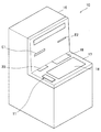
まず、一般的な第1の自動取引装置について説明する。図1は、一般的な第1の自動取引装置10の外観を示す斜視図である。まず、図1を参照しながら、一般的な第1の自動取引装置10の外部構成について説明する。例えば、自動取引装置10は、紙幣を還流させる(リサイクルさせる)タイプのATMに代表される顧客操作型端末であってよい。また、自動取引装置10は、銀行、駅構内およびコンビニエンスストアなど、多様な場所に設置され得る。
First, a general first automatic transaction apparatus will be described. FIG. 1 is a perspective view showing an external appearance of a general first
図1を参照すると、自動取引装置10は、ハンドセット11と、硬貨入出金口20と、伝票排出部E1と、装置本体16と、カード挿入排出口E2と、紙幣入出金口19と、表示部18と、フロントパネル17とを備える。表示部18には、利用者が操作を入力するためのタッチパネルが積層されていてよい。自動取引装置10の動作の例として出金の動作を説明する。
Referring to FIG. 1, an
まず、利用者がカードをカード挿入排出口E2に挿入すると、暗証情報の入力案内が表示部18に表示される。利用者は暗証情報を入力する。カードから読み取られたデータに基づいて暗証情報の照合が成功すると、利用者は払い戻したい金額を入力し、表示部18に表示された確認ボタンを押下する操作を行う。入力された金額に相当する現金が紙幣入出金口19または硬貨入出金口20に排出され、伝票が伝票排出部E1に排出されると、利用者は現金と伝票とを受け取り、取引が完了する。取引明細は、伝票排出部E1から出力される。
First, when the user inserts a card into the card insertion / ejection slot E2, password information input guidance is displayed on the
ハンドセット11は、自動取引装置10の利用者を案内するための音声ガイダンスを出力し得る。音声ガイダンスは、視覚障害者向けの音声ガイダンスであってもよい。また、かかるハンドセットが、電話網を経由して受信された音声を出力する機能をさらに有する。例えば、健常者が係員と通話を行いたい場合に、かかる機能が利用され得る。
The
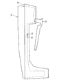
ここで、ハンドセット11は利用されないときには収納部に収納されるのが一般的である。図2は、一般的な第1の自動取引装置10のうち収納部12に収納されているハンドセット11およびその周辺を拡大して示した側面図である。図2を参照すると、収納部12にハンドセット11が収納されている。しかし、意図しないときにハンドセット11が収納部12から外れてしまうことがある。
Here, when the
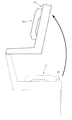
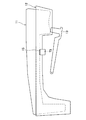
また、収納部12が開閉部材に設けられる場合には、開閉部材が開いたときにハンドセット11が収納部12から特に外れやすい。本明細書においては、開閉部材が、図1に示したように自動取引装置10の前面に存在するフロントパネル17である場合を例として説明するが、開閉部材の位置は自動取引装置10の前面に限定されない。図3は、フロントパネル17が開いている状態を示す側面図である。図3に示すように、フロントパネル17が開いている状態のときには、フロントパネル17が傾いてしまうため、ハンドセット11が所望の位置から外れやすい。
When the
ハンドセット11が収納部から外れると、ハンドセット11が自動的に電話網に接続されてしまうこともある。また、ハンドセット11が収納部から外れると、ハンドセット11から自動的に音声ガイダンスが出力されることもある。そこで、ハンドセット11が収納部から外れることを妨げるために、磁石の磁力が用いられることがある。図2を参照すると、収納部12には磁石14が設けられ、ハンドセット11には鉄板15が設けられている。そして、ハンドセット11が収納部12に収納されているときには、磁石14の磁力により鉄板15が磁石14に吸着されるため、ハンドセット11が収納部12から外れることが妨げられる。
When the
さらに、収納部12の下方には、フックスイッチ13が設けられており、ハンドセット11が収納部12に収納されるときには、フックスイッチ13がハンドセット11から押圧を受ける。ハンドセット11から押圧を受けると、フックスイッチ13は、回動中心を支点としてハンドセット11との接触部分が下降する方向に回動し、所定の位置において停止する。ハンドセット11が収納部12に収納されている状態においては、フックスイッチ13がハンドセット11から押圧を受ける。
Further, a
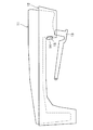
一方、ハンドセット11が収納部12から取り外されるときには、フックスイッチ13がハンドセット11から受ける押圧が解除される。フックスイッチ13がハンドセット11から受ける押圧が解除されると、フックスイッチ13は、回動中心を支点としてハンドセット11との接触部分が上昇する方向に回動し、所定の位置において停止する。フックスイッチ13がハンドセット11から受ける押圧の解除によってハンドセット11が収納部12から外れたことが検出され得る。
On the other hand, when the
しかし、ハンドセット11が収納部12から外れることを妨げるために設けられる磁石14が磁気媒体に何らかの影響を与えてしまう可能性がある。例えば、磁気媒体としては、例えば、通帳に付された磁気媒体、カードなどに付された磁気媒体などが挙げられる。磁気媒体への影響としては、磁気媒体の磁気ストライプに記録されている情報が消去されてしまうという影響などが想定される。また、図2には、収納部12の上面に磁石14が設けられる例が示されていたが、収納部12のうちハンドセット11の受話部が収まる窪み部分の側面に磁石14を設けることによって磁石14が磁気媒体に与える影響を低減することも想定される。
However, there is a possibility that the
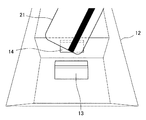
図4は、一般的な第2の自動取引装置10のうち収納部12に収納されているハンドセット11およびその周辺を拡大して示した側面図である。図4に示したように、収納部12のうちハンドセット11の受話部が収まる窪み部分の側面に磁石14が設けられることによって、水平に置かれた磁気媒体に対して磁石14が与える影響は低減されることが期待される。しかし、収納部12のうちハンドセット11の受話部が収まる窪み部分に磁気媒体が入り込むことも想定される。図5は、一般的な第2の自動取引装置10のうち磁気媒体21に接近された収納部12およびその周辺を拡大して示した斜視図である。
FIG. 4 is an enlarged side view of the
図5を参照すると、収納部12のうちハンドセット11の受話部が収まる窪み部分の側面に磁石14が設けられている。しかし、図5に示したように、この窪み部分には、磁気媒体21が入り込む場合も想定される。かかる場合には、収納部12の上面に磁石14が設けられる場合と同様に、磁石14が磁気媒体21に何らかの影響を与えてしまう可能性がある。そこで、本明細書においては、ハンドセット11が収納部12から外れることを妨げるために設けられる磁石14が磁気媒体21に与える影響を低減することが可能な技術を主に提案する。
Referring to FIG. 5, a
なお、図2に示した例においては、磁石14に吸着される物質としては、鉄板15が用いられているが、磁石14に吸着される物質は鉄板15に限定されない。例えば、磁石14に吸着される物質として、鉄板15の代わりに他の磁性体(例えば、コバルト、ニッケルなど)が用いられてもよい。
In the example shown in FIG. 2, the
(第1の実施形態)
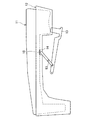
続いて、本発明の第1の実施形態について説明する。ここで、本発明の第1の実施形態に係る構成のうち、上記した一般的な技術と同様の構成には、一般的な技術に係る構成と同一の符号を付し、一般的な技術に係る構成と同様の構成についての詳細な説明を省略する場合がある。図6は、本発明の第1の実施形態に係る自動取引装置10のうち収納部12に収納されているハンドセット11およびその周辺を拡大して示した側面図である。
(First embodiment)
Subsequently, a first embodiment of the present invention will be described. Here, among the configurations according to the first embodiment of the present invention, the same reference numerals as the configurations related to the general technology are attached to the configurations similar to the general technology described above, and the general technology is added. A detailed description of the same configuration as this configuration may be omitted. FIG. 6 is an enlarged side view showing the
図6を参照すると、収納部12にハンドセット11が収納されている。また、収納部12には磁石14が設けられ、ハンドセット11には鉄板15が設けられている。そして、ハンドセット11が収納部12に収納されているときには、磁石14の磁力により鉄板15が磁石14に吸着されるため、ハンドセット11が収納部12から外れることが妨げられる。また、収納部12の下方には、フックスイッチ13が設けられている。ハンドセット11が収納部12に収納されているときには、フックスイッチ13がハンドセット11から押圧を受けている。
Referring to FIG. 6, the
また、図6を参照すると、フックスイッチ13と磁石14とを接続するリンク部材53が設けられている。ここで、収納部12からハンドセット11が取り外されてハンドセット11からフックスイッチ13への押圧が解除されると、リンク部材53は、ハンドセット11からフックスイッチ13への押圧の解除に連動して回動することによって磁石14を移動させる。かかる構成によれば、ハンドセット11が収納部12から外れることを妨げるために設けられる磁石14が磁気媒体21に与える影響を低減することが可能となる。
Referring to FIG. 6, a
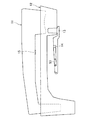
図7は、本発明の第1の実施形態に係る自動取引装置10のうち収納部12から取り外されたハンドセット11およびその周辺を拡大して示した側面図である。図7に示したように、収納部12からハンドセット11が取り外されてハンドセット11からフックスイッチ13への押圧が解除されると、リンク部材53は、ハンドセット11からフックスイッチ13への押圧の解除に連動して回動することによって磁石14をハンドセット11から遠ざける方向に移動させるとよい。
FIG. 7 is an enlarged side view of the
具体的には、図6に示したように、フックスイッチ13は回動可能に構成されており、リンク部材53も回動可能に構成されている。ここで、リンク部材53は、リンク部材53の回動中心を基準としてフックスイッチ13との接続位置とは反対側に磁石14が接続されているとよい。そうすれば、図7に示したように、リンク部材53は、フックスイッチ13に対するハンドセット11からの押圧が解除されるとフックスイッチ13の回動方向とは逆方向に回動して、磁石14をハンドセット11から遠ざける方向に移動させることが可能となる。
Specifically, as shown in FIG. 6, the
以上、本発明の第1の実施形態に係る構成のうち、一般的な技術に係る構成とは異なる構成について主に説明した。 As above, the configuration according to the first embodiment of the present invention that is different from the configuration according to the general technique has been mainly described.
(第2の実施形態)
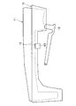
続いて、本発明の第2の実施形態について説明する。ここで、本発明の第2の実施形態に係る構成のうち、本発明の第1の実施形態と同様の構成には、本発明の第1の実施形態の構成と同一の符号を付し、本発明の第1の実施形態と同様の構成についての詳細な説明を省略する場合がある。図8は、本発明の第2の実施形態に係る自動取引装置10のうち収納部12に収納されているハンドセット11およびその周辺を拡大して示した側面図である。
(Second Embodiment)
Subsequently, a second embodiment of the present invention will be described. Here, among the configurations according to the second embodiment of the present invention, the same reference numerals as the configurations of the first embodiment of the present invention are attached to the configurations similar to the first embodiment of the present invention, A detailed description of the same configuration as that of the first embodiment of the present invention may be omitted. FIG. 8 is an enlarged side view of the
図8を参照すると、収納部12にハンドセット11が収納されている。また、収納部12の下方には、フックスイッチ13が設けられており、ハンドセット11には鉄板15が設けられている。ここで、本発明の第1の実施形態においては、ハンドセット11が収納部12から外れることを妨げる磁石が収納部12に設けられる例を示した。本発明の第2の実施形態においては、収納部12に電磁石63が設けられる例を説明する。
Referring to FIG. 8, the
具体的には、フックスイッチ13は、ハンドセット11が収納部12に収納されてハンドセット11から押圧を受けているときには、電磁石63への電流の供給を継続させればよい。電磁石63が電流の供給を受けることによって磁化されると、磁力により鉄板15が電磁石63に吸着される。そのため、ハンドセット11が収納部12から外れることが妨げられる。
Specifically, the
一方、フックスイッチ13は、収納部12からハンドセット11が取り外されてハンドセット11から受ける押圧が解除されると、ハンドセット11から受ける押圧の解除に連動して電磁石63への電流の供給を停止させればよい。かかる構成によれば、収納部12からハンドセット11が取り外されたときには、電磁石63が消磁されるため、ハンドセット11が収納部12から外れることを妨げるために設けられる電磁石63が磁気媒体に与える影響を低減することが可能となる。以下、電磁石63に電流を供給する回路の具体的な構成を説明する。
On the other hand, when the
図9は、本発明の第2の実施形態に係る自動取引装置10のうち電磁石63に電流を供給する回路の構成例を示す図である。フックスイッチ13は、ハンドセット11が収納部12に収納され、ハンドセット11との接触部分が下降する方向に回動すると、電磁石63に電流を供給するための回路を接続する。これによって、電磁石63への電流の供給が継続される。一方、フックスイッチ13は、収納部12からハンドセット11が取り外され、ハンドセット11との接触部分が上昇する方向に回動すると、電磁石63に電流を供給するための回路を切断する。これによって、電磁石63への電流の供給が停止される。
FIG. 9 is a diagram illustrating a configuration example of a circuit for supplying current to the
なお、電磁石63に電流を供給するための電源は、自動取引装置10に電力を供給する電源と同じであってもよい。しかし、図9に示した例では、電磁石63に電流を供給するための回路に、DC(Direct Current)電源64および電池65が別途設けられている。このように、電磁石63に電流を供給するための回路に、自動取引装置10に電力を供給する電源とは異なる電源を設けることによって、自動取引装置10への電力供給が停止された場合であっても、電磁石63に供給する電流を制御することが可能である。
The power source for supplying current to the
また、図9に示されるように、電磁石63に電流を供給するための回路に逆電流防止用ダイオード66が設けられてもよい。
Further, as shown in FIG. 9, a reverse
以上、本発明の第2の実施形態に係る構成のうち、本発明の第1の実施形態に係る構成とは異なる構成について主に説明した。 Heretofore, the configuration different from the configuration according to the first embodiment of the present invention has been mainly described among the configurations according to the second embodiment of the present invention.
(第3の実施形態)
続いて、本発明の第3の実施形態について説明する。ここで、本発明の第3の実施形態に係る構成のうち、本発明の第1および第2の実施形態と同様の構成には、本発明の第1および第2の実施形態の構成と同一の符号を付し、本発明の第1および第2の実施形態と同様の構成についての詳細な説明を省略する場合がある。図10は、本発明の第3の実施形態に係る自動取引装置10のうち収納部12に収納されているハンドセット11およびその周辺を拡大して示した側面図である。
(Third embodiment)
Subsequently, a third embodiment of the present invention will be described. Here, in the configuration according to the third embodiment of the present invention, the same configuration as the first and second embodiments of the present invention is the same as the configuration of the first and second embodiments of the present invention. A detailed description of the same configuration as in the first and second embodiments of the present invention may be omitted. FIG. 10 is an enlarged side view showing the
図8を参照すると、収納部12にハンドセット11が収納されている。また、収納部12の下方には、フックスイッチ13が設けられており、ハンドセット11には鉄板15が設けられている。ここで、本発明の第3の実施形態においても、本発明の第2の実施形態と同様に、収納部12に電磁石73が設けられる例を説明する。ただし、本発明の第3の実施形態においては、ハンドセット11が置かれるフロントパネル17が開いているか否かを検出する開閉検出スイッチを用いる。
Referring to FIG. 8, the
図11は、本発明の第3の実施形態に係る自動取引装置10のうち開いた状態におけるフロントパネル17およびその周辺を拡大して示した側面図である。図11を参照すると、ハンドセット11が置かれるフロントパネル17には、開閉検出スイッチ75が設けられている。開閉検出スイッチ75は、フロントパネル17が開いているか否かを検出することが可能である。図11に示した例では、開閉検出スイッチ75がフロントパネル17の下面に設けられているが、開閉検出スイッチ75は設けられる位置は特に限定されない。
FIG. 11 is an enlarged side view of the
本発明の第3の実施形態においては、開閉検出スイッチ75は、フロントパネル17が開けられ、フロントパネル17が開いていることを検出したときに電磁石73への電流の供給を継続させればよい。電磁石73が電流の供給を受けることによって磁化されると、磁力により鉄板15が電磁石73に吸着される。そのため、ハンドセット11が収納部12から外れることが妨げられる。
In the third embodiment of the present invention, the open /
一方、開閉検出スイッチ75は、フロントパネル17が閉じられ、フロントパネル17が閉じていることを検出したときに電磁石73への電流の供給を停止させればよい。かかる構成によれば、フロントパネル17が閉じられたときには、電磁石73が消磁されるため、ハンドセット11が収納部12から外れることを妨げるために設けられる電磁石73が磁気媒体に与える影響を低減することが可能となる。
On the other hand, the open /
さらに、かかる構成によれば、ハンドセット11が収納部12に収納されているときであっても、フロントパネル17が閉じている限りにおいては、電磁石73への電流の供給が停止されて電磁石73が消磁される。そのため、ハンドセット11が収納部12に収納されているときであっても、フロントパネル17が閉じている限りにおいては、電磁石73と鉄板15との吸着がされないため、収納部12からハンドセット11を取り外すときに利用者に与える抵抗感を低減することができる。以下、電磁石73に電流を供給する回路の具体的な構成を説明する。
Furthermore, according to this configuration, even when the
図12は、本発明の第3の実施形態に係る自動取引装置10のうち電磁石73に電流を供給する回路の構成例を示す図である。開閉検出スイッチ75は、フロントパネル17が開かれ、装置本体16から押圧を受けていないときには、電磁石73に電流を供給するための回路を接続する。これによって、電磁石73への電流の供給が継続される。一方、開閉検出スイッチ75は、フロントパネル17が閉じられ、装置本体16から押圧を受けているときは、電磁石73に電流を供給するための回路を切断する。これによって、電磁石73への電流の供給が停止される。
FIG. 12 is a diagram illustrating a configuration example of a circuit that supplies current to the
なお、電磁石73に電流を供給するための電源は、自動取引装置10に電力を供給する電源と同じであってもよい。しかし、図12に示したように、本発明の第2の実施形態と同様に、電磁石73に電流を供給するための回路には、DC電源64および電池65が別途設けられてもよい。また、図12に示したように、本発明の第2の実施形態と同様に、電磁石73に電流を供給するための回路に逆電流防止用ダイオード66が設けられてもよい。
The power source for supplying current to the
以上、本発明の第3の実施形態に係る構成のうち、本発明の第1および第2の実施形態に係る構成とは異なる構成について主に説明した。 Heretofore, the configuration different from the configurations according to the first and second embodiments of the present invention has been mainly described among the configurations according to the third embodiment of the present invention.
以上、添付図面を参照しながら本発明の好適な実施形態について詳細に説明したが、本発明はかかる例に限定されない。本発明の属する技術の分野における通常の知識を有する者であれば、特許請求の範囲に記載された技術的思想の範疇内において、各種の変更例または修正例に想到し得ることは明らかであり、これらについても、当然に本発明の技術的範囲に属するものと了解される。 The preferred embodiments of the present invention have been described in detail above with reference to the accompanying drawings, but the present invention is not limited to such examples. It is obvious that a person having ordinary knowledge in the technical field to which the present invention pertains can come up with various changes or modifications within the scope of the technical idea described in the claims. Of course, it is understood that these also belong to the technical scope of the present invention.
10 自動取引装置
11 ハンドセット
12 収納部
13 フックスイッチ
14 磁石
15 鉄板
16 装置本体
17 フロントパネル
18 表示部
19 紙幣入出金口
20 硬貨入出金口
21 磁気媒体
53 リンク部材
63 電磁石
64 DC電源
65 電池
66 逆電流防止用ダイオード
73 電磁石
75 開閉検出スイッチ
E1 伝票排出部
E2 カード挿入排出口
DESCRIPTION OF
Claims (5)
磁力によってハンドセットが前記収納部から外れることを妨げる磁石と、
前記ハンドセットから前記フックスイッチへの押圧の解除に連動して回動することによって前記磁石を移動させるリンク部材と、
を備える、自動取引装置。 A hook switch that receives pressure from the handset when the handset is stored in the storage unit, and releases the pressure from the handset when the handset is removed from the storage unit;
A magnet that prevents the handset from being detached from the storage by magnetic force;
A link member that moves the magnet by rotating in conjunction with the release of the pressure from the handset to the hook switch;
An automatic transaction apparatus comprising:
請求項1に記載の自動取引装置。 The link member moves in a direction away from the handset by rotating in conjunction with the release of the pressure from the handset to the hook switch,
The automatic transaction apparatus according to claim 1.
請求項2に記載の自動取引装置。 The link member is connected to the opposite side of the connection position with the hook switch with respect to the rotation center, and when the pressure from the handset is released, the direction of rotation of the hook switch is opposite. To move the magnet away from the handset,
The automatic transaction apparatus according to claim 2.
電流の供給を受けることによって磁化されて前記ハンドセットが収納部から外れることを妨げる電磁石と、を備え、
前記開閉部材が開いていることを前記開閉検出スイッチが検出したときに、前記電磁石への電流の供給を継続させ、前記開閉部材が閉じていることを前記開閉検出スイッチが検出したときに、前記電流を停止させることによって前記電磁石を消磁させ、
前記ハンドセットの利用時に前記ハンドセットが前記収納部から外されるに際して、前記開閉部材が閉じており、前記電磁石が消磁されている、
自動取引装置。 An open / close detection switch for detecting whether the open / close member on which the handset is placed is open;
An electromagnet that is magnetized by receiving a supply of current and prevents the handset from being removed from the storage unit,
When the open / close detection switch detects that the open / close member is open, the supply of current to the electromagnet is continued, and when the open / close detection switch detects that the open / close member is closed, Demagnetizing the electromagnet by stopping the current,
When the handset is removed from the storage unit when the handset is used, the opening / closing member is closed and the electromagnet is demagnetized.
Automatic transaction device.
請求項4に記載の自動取引装置。
Circuit for the opening and closing detection switch is provided in the closing member, to supply current to the prior SL electromagnet when said opening and closing detecting switch the opening and closing member is closed is under pressure from the main body of the automatic teller machine cutting and connecting the circuit for supplying the current to the previous SL electromagnet when the pressing is released from the main body with respect to the opening and closing detecting switch the opening and closing member is opened,
The automatic transaction apparatus according to claim 4.
Priority Applications (1)
| Application Number | Priority Date | Filing Date | Title |
|---|---|---|---|
| JP2014071381A JP6451069B2 (en) | 2014-03-31 | 2014-03-31 | Automatic transaction equipment |
Applications Claiming Priority (1)
| Application Number | Priority Date | Filing Date | Title |
|---|---|---|---|
| JP2014071381A JP6451069B2 (en) | 2014-03-31 | 2014-03-31 | Automatic transaction equipment |
Publications (2)
| Publication Number | Publication Date |
|---|---|
| JP2015194821A JP2015194821A (en) | 2015-11-05 |
| JP6451069B2 true JP6451069B2 (en) | 2019-01-16 |
Family
ID=54433794
Family Applications (1)
| Application Number | Title | Priority Date | Filing Date |
|---|---|---|---|
| JP2014071381A Active JP6451069B2 (en) | 2014-03-31 | 2014-03-31 | Automatic transaction equipment |
Country Status (1)
| Country | Link |
|---|---|
| JP (1) | JP6451069B2 (en) |
Family Cites Families (6)
| Publication number | Priority date | Publication date | Assignee | Title |
|---|---|---|---|---|
| JPH0445319Y2 (en) * | 1989-12-29 | 1992-10-26 | ||
| JPH04116457U (en) * | 1991-03-27 | 1992-10-19 | 村田機械株式会社 | Wall-mounted fax machine |
| JPH05268309A (en) * | 1992-03-19 | 1993-10-15 | Fujitsu Ltd | Hand set hook structure for car telephone |
| JPH0626343U (en) * | 1992-09-02 | 1994-04-08 | 株式会社船井電機研究所 | Phone lock mechanism |
| JPH09147182A (en) * | 1995-11-28 | 1997-06-06 | Toshiba Corp | Facing type automatic transaction device |
| JP2013073391A (en) * | 2011-09-27 | 2013-04-22 | Oki Electric Ind Co Ltd | Automatic transaction device |
-
2014
- 2014-03-31 JP JP2014071381A patent/JP6451069B2/en active Active
Also Published As
| Publication number | Publication date |
|---|---|
| JP2015194821A (en) | 2015-11-05 |
Similar Documents
| Publication | Publication Date | Title |
|---|---|---|
| US9881290B2 (en) | Point-of-sale system | |
| JP6451069B2 (en) | Automatic transaction equipment | |
| JP2007265316A (en) | Biometrics system and automatic transaction apparatus using the same | |
| JP2009157595A (en) | Automatic transaction device and automatic transaction system | |
| JP6070358B2 (en) | Medium communication system and automatic transaction apparatus | |
| WO2012063577A1 (en) | Automatic transaction device | |
| KR20100072606A (en) | Anti-skimming apparatus for atm | |
| CN101676962B (en) | Automatic trading device | |
| JP2013191037A (en) | Automatic teller machine, and anti-skimming method of automatic teller machine | |
| JP2009301098A (en) | Automatic transaction device | |
| JP3694823B2 (en) | Automatic transaction equipment | |
| JP2001126120A (en) | Automatic transaction machine | |
| JP2010033189A (en) | Automated teller machine | |
| JP2006338403A (en) | Automatic transaction device | |
| JP6265004B2 (en) | Input key arrangement structure and automatic transaction device | |
| JP2015184976A (en) | Automatic transaction device | |
| JP5140452B2 (en) | Rental locker system | |
| JP2018032136A (en) | Automatic transaction device | |
| JP2007004653A (en) | Automated teller machine | |
| JPWO2016143222A1 (en) | Automatic transaction equipment | |
| JPH05324987A (en) | Automatic transaction device for visually handicapped person | |
| JP6822642B2 (en) | Money changer, arcade equipment and currency exchange method | |
| KR20100124478A (en) | Cash transaction machine | |
| JP5260377B2 (en) | Automatic deposit payment machine and its transfer deterrence method | |
| JP2008259895A (en) | Game medium counting system |
Legal Events
| Date | Code | Title | Description |
|---|---|---|---|
| A621 | Written request for application examination |
Free format text: JAPANESE INTERMEDIATE CODE: A621 Effective date: 20161115 |
|
| A977 | Report on retrieval |
Free format text: JAPANESE INTERMEDIATE CODE: A971007 Effective date: 20170922 |
|
| A131 | Notification of reasons for refusal |
Free format text: JAPANESE INTERMEDIATE CODE: A131 Effective date: 20171003 |
|
| A521 | Written amendment |
Free format text: JAPANESE INTERMEDIATE CODE: A523 Effective date: 20171129 |
|
| A131 | Notification of reasons for refusal |
Free format text: JAPANESE INTERMEDIATE CODE: A131 Effective date: 20180424 |
|
| A521 | Written amendment |
Free format text: JAPANESE INTERMEDIATE CODE: A523 Effective date: 20180611 |
|
| TRDD | Decision of grant or rejection written | ||
| A01 | Written decision to grant a patent or to grant a registration (utility model) |
Free format text: JAPANESE INTERMEDIATE CODE: A01 Effective date: 20181113 |
|
| A61 | First payment of annual fees (during grant procedure) |
Free format text: JAPANESE INTERMEDIATE CODE: A61 Effective date: 20181126 |
|
| R150 | Certificate of patent or registration of utility model |
Ref document number: 6451069 Country of ref document: JP Free format text: JAPANESE INTERMEDIATE CODE: R150 |