JP6412944B2 - Component mounting equipment - Google Patents
Component mounting equipment Download PDFInfo
- Publication number
- JP6412944B2 JP6412944B2 JP2016546267A JP2016546267A JP6412944B2 JP 6412944 B2 JP6412944 B2 JP 6412944B2 JP 2016546267 A JP2016546267 A JP 2016546267A JP 2016546267 A JP2016546267 A JP 2016546267A JP 6412944 B2 JP6412944 B2 JP 6412944B2
- Authority
- JP
- Japan
- Prior art keywords
- component
- hole
- temporary placement
- pressure
- unit
- Prior art date
- Legal status (The legal status is an assumption and is not a legal conclusion. Google has not performed a legal analysis and makes no representation as to the accuracy of the status listed.)
- Active
Links
Images


Classifications
-
- H—ELECTRICITY
- H05—ELECTRIC TECHNIQUES NOT OTHERWISE PROVIDED FOR
- H05K—PRINTED CIRCUITS; CASINGS OR CONSTRUCTIONAL DETAILS OF ELECTRIC APPARATUS; MANUFACTURE OF ASSEMBLAGES OF ELECTRICAL COMPONENTS
- H05K13/00—Apparatus or processes specially adapted for manufacturing or adjusting assemblages of electric components
- H05K13/04—Mounting of components, e.g. of leadless components
- H05K13/046—Surface mounting
-
- H—ELECTRICITY
- H05—ELECTRIC TECHNIQUES NOT OTHERWISE PROVIDED FOR
- H05K—PRINTED CIRCUITS; CASINGS OR CONSTRUCTIONAL DETAILS OF ELECTRIC APPARATUS; MANUFACTURE OF ASSEMBLAGES OF ELECTRICAL COMPONENTS
- H05K13/00—Apparatus or processes specially adapted for manufacturing or adjusting assemblages of electric components
- H05K13/04—Mounting of components, e.g. of leadless components
- H05K13/0417—Feeding with belts or tapes
-
- H—ELECTRICITY
- H05—ELECTRIC TECHNIQUES NOT OTHERWISE PROVIDED FOR
- H05K—PRINTED CIRCUITS; CASINGS OR CONSTRUCTIONAL DETAILS OF ELECTRIC APPARATUS; MANUFACTURE OF ASSEMBLAGES OF ELECTRICAL COMPONENTS
- H05K13/00—Apparatus or processes specially adapted for manufacturing or adjusting assemblages of electric components
- H05K13/08—Monitoring manufacture of assemblages
- H05K13/082—Integration of non-optical monitoring devices, i.e. using non-optical inspection means, e.g. electrical means, mechanical means or X-rays
-
- Y—GENERAL TAGGING OF NEW TECHNOLOGICAL DEVELOPMENTS; GENERAL TAGGING OF CROSS-SECTIONAL TECHNOLOGIES SPANNING OVER SEVERAL SECTIONS OF THE IPC; TECHNICAL SUBJECTS COVERED BY FORMER USPC CROSS-REFERENCE ART COLLECTIONS [XRACs] AND DIGESTS
- Y10—TECHNICAL SUBJECTS COVERED BY FORMER USPC
- Y10T—TECHNICAL SUBJECTS COVERED BY FORMER US CLASSIFICATION
- Y10T29/00—Metal working
- Y10T29/49—Method of mechanical manufacture
- Y10T29/49002—Electrical device making
- Y10T29/49004—Electrical device making including measuring or testing of device or component part
-
- Y—GENERAL TAGGING OF NEW TECHNOLOGICAL DEVELOPMENTS; GENERAL TAGGING OF CROSS-SECTIONAL TECHNOLOGIES SPANNING OVER SEVERAL SECTIONS OF THE IPC; TECHNICAL SUBJECTS COVERED BY FORMER USPC CROSS-REFERENCE ART COLLECTIONS [XRACs] AND DIGESTS
- Y10—TECHNICAL SUBJECTS COVERED BY FORMER USPC
- Y10T—TECHNICAL SUBJECTS COVERED BY FORMER US CLASSIFICATION
- Y10T29/00—Metal working
- Y10T29/49—Method of mechanical manufacture
- Y10T29/49002—Electrical device making
- Y10T29/49117—Conductor or circuit manufacturing
- Y10T29/49124—On flat or curved insulated base, e.g., printed circuit, etc.
- Y10T29/4913—Assembling to base an electrical component, e.g., capacitor, etc.
- Y10T29/49131—Assembling to base an electrical component, e.g., capacitor, etc. by utilizing optical sighting device
-
- Y—GENERAL TAGGING OF NEW TECHNOLOGICAL DEVELOPMENTS; GENERAL TAGGING OF CROSS-SECTIONAL TECHNOLOGIES SPANNING OVER SEVERAL SECTIONS OF THE IPC; TECHNICAL SUBJECTS COVERED BY FORMER USPC CROSS-REFERENCE ART COLLECTIONS [XRACs] AND DIGESTS
- Y10—TECHNICAL SUBJECTS COVERED BY FORMER USPC
- Y10T—TECHNICAL SUBJECTS COVERED BY FORMER US CLASSIFICATION
- Y10T29/00—Metal working
- Y10T29/53—Means to assemble or disassemble
- Y10T29/5313—Means to assemble electrical device
- Y10T29/53191—Means to apply vacuum directly to position or hold work part
Description
本発明は、部品実装装置に関する。 The present invention relates to a component mounting apparatus.
従来より、基板に部品を実装する部品実装装置において、テープやトレイに並べられた部品をノズルで吸着したあと、そのノズルを基板上へ移動し、その基板の所定位置でノズルの吸着を解除してその部品を実装するものが知られている。こうした部品実装装置において、ノズルが部品を吸着したあと基板上へ移動する前に、仮置き面上で部品の吸着を解除して部品を仮置き面に載置するものも知られている(特許文献1参照)。仮置き面に載置された部品は、保持位置のずれの修正が行われたあと、再度部品をノズルに吸着されて基板上へ移動される。特許文献1には、仮置き面に負圧供給穴を設ける点も記載されている。この仮置き面に載置された部品は、負圧供給穴に負圧を供給することで仮置き面上で動かないように固定される。
Conventionally, in a component mounting apparatus that mounts components on a board, after sucking the components arranged on a tape or tray with a nozzle, the nozzle is moved onto the board and the nozzle is released from the suction at a predetermined position on the board. The one that mounts the component is known. In such a component mounting apparatus, there is also known a device in which suction of a component is released on the temporary placement surface and the component is placed on the temporary placement surface before the nozzle moves to the substrate after the component is attracted (patent) Reference 1). After the component placed on the temporary placement surface is corrected for the shift of the holding position, the component is again attracted to the nozzle and moved onto the substrate.
しかしながら、ノズルが仮置き面上で部品の吸着を解除して部品を仮置き面に載置する動作を実施したとき、部品を仮置き面上に載置するのを失敗することがある。その場合、こうした動作を実施したあとに仮置き面上を撮像して部品の有無をチェックすることも考えられるが、画像処理に時間がかかるため、部品の実装に要する時間が長くなり、スループット(単位時間あたりの部品実装能力)が低下するという問題があった。 However, when the nozzle performs the operation of releasing the suction of the component on the temporary placement surface and placing the component on the temporary placement surface, it may fail to place the component on the temporary placement surface. In such a case, it may be possible to check the presence or absence of a component by imaging the temporary placement surface after performing such an operation. However, since it takes time to process the image, the time required for mounting the component becomes longer, and the throughput ( There has been a problem that the component mounting capacity per unit time is reduced.
本発明は、上記課題を解決するためになされたものであり、部品実装装置において、仮置き面に部品が実際に仮置きされたか否かの判定を迅速に行うことを主目的とする。 The present invention has been made to solve the above-described problem, and has as its main object to quickly determine whether or not a component is actually temporarily placed on a temporary placement surface in a component mounting apparatus.
本発明の部品実装装置は、
部品を供給する部品供給手段と、
前記部品を吸着可能な部品吸着手段と、
前記部品吸着手段を移動させる移動手段と、
前記部品が実装される基板を保持する基板保持手段と、
所定位置に穴を有し、前記部品を前記所定位置に仮置きするための仮置き面と、
前記穴に少なくとも負圧を供給可能な圧力調節手段と、
前記穴の圧力を検出する圧力検出手段と、
前記部品供給手段によって供給された部品を前記部品吸着手段が吸着した後前記基板上に実装する前に前記部品が前記所定位置に仮置きされるよう前記部品吸着手段及び前記移動手段を制御する制御手段と、
を備え、
前記制御手段は、前記部品が前記所定位置に仮置きされるよう制御した後、前記穴に負圧を供給した状態で前記穴の圧力状態に基づいて前記所定位置に前記部品が実際に仮置きされたか否かを判定し、該判定の結果に応じた処理を実行する
ものである。The component mounting apparatus of the present invention is
Parts supply means for supplying parts;
Component adsorbing means capable of adsorbing the component;
Moving means for moving the component suction means;
Board holding means for holding a board on which the component is mounted;
Having a hole at a predetermined position, and a temporary placement surface for temporarily placing the component at the predetermined position;
Pressure adjusting means capable of supplying at least negative pressure to the hole;
Pressure detecting means for detecting the pressure of the hole;
Control for controlling the component suction unit and the moving unit so that the component is temporarily placed at the predetermined position after the component suction unit sucks the component supplied by the component supply unit and before the component is mounted on the substrate. Means,
With
The control means controls the part to be temporarily placed at the predetermined position, and then the part is actually temporarily placed at the predetermined position based on the pressure state of the hole with negative pressure supplied to the hole. It is determined whether or not it has been performed, and processing according to the result of the determination is executed.
この部品実装装置は、部品供給手段によって供給された部品を部品吸着手段が吸着した後基板上に実装する前にその部品が仮置き面の所定位置に仮置きされるよう制御する。また、部品実装装置は、部品が所定位置に仮置きされるように制御した後、穴に負圧を供給した状態で穴の圧力状態に基づいて所定位置に部品が実際に仮置きされたか否かを判定し、該判定の結果に応じた処理を実行する。このように仮置き面の穴の圧力状態に基づいて部品が実際に仮置きされたか否かを判定するため、その判定を迅速に行うことができる。したがって、スループットが向上する。 The component mounting apparatus controls the component supplied by the component supply unit so that the component is temporarily placed at a predetermined position on the temporary placement surface before being mounted on the substrate after the component suction unit sucks the component. In addition, the component mounting apparatus controls whether or not the component is temporarily placed at a predetermined position, and then whether or not the component is actually temporarily placed at a predetermined position based on the pressure state of the hole while negative pressure is supplied to the hole. And processing according to the result of the determination is executed. In this way, since it is determined whether or not the part has actually been temporarily placed based on the pressure state of the hole on the temporary placement surface, the determination can be made quickly. Therefore, the throughput is improved.
本発明の部品実装装置において、前記仮置き面は、平坦面であることが好ましい。一般に部品供給手段が部品を供給する場合、その部品はテープやトレイなどを用いて供給されるが、テープやトレイなどは平坦性が良くないため、部品ががたつきやすい。そのため、部品供給手段によって供給された部品を部品吸着手段が吸着するとき、予め定めた特定の位置を精度よく吸着することは困難である。しかし、ここでは仮置き面が平坦面であるため、この仮置き面に載置された部品を部品吸着手段が再吸着する際には、特定の位置を精度よく吸着することができる。 In the component mounting apparatus of the present invention, it is preferable that the temporary placement surface is a flat surface. In general, when a component supply means supplies a component, the component is supplied using a tape, a tray, or the like. However, the tape or the tray is not flat and the component is likely to be rattled. For this reason, when the component suction unit sucks the component supplied by the component supply unit, it is difficult to accurately suck a predetermined specific position. However, since the temporary placement surface is a flat surface here, when the component suction means re-sucks the component placed on the temporary placement surface, the specific position can be suctioned with high accuracy.
本発明の部品実装装置は、前記部品吸着手段に吸着された部品を側方から撮像可能な側方撮像手段を備え、前記制御手段は、前記判定の結果が否定判定ならば、前記側方撮像手段に前記部品吸着手段を撮像させ、該撮像された画像に基づいて前記部品吸着手段が前記部品を吸着しているか否かを判定し、その判定結果を作業者に報知して前記一連の処理を中止してもよい。こうすれば、実際には仮置き面に部品が仮置きされていなかった場合、部品吸着手段に部品が吸着されたままなのか否かを作業者に知らせるため、作業者は仮置きされなかった部品を容易に探すことができる。 The component mounting apparatus of the present invention includes a side imaging unit capable of imaging a component adsorbed by the component adsorbing unit from the side, and the control unit is configured to capture the side image if the determination result is negative. The component picking-up means is picked up by the means, and it is determined whether or not the component picking-up means is picking up the part based on the picked-up image, and the determination result is notified to the operator to perform the series of processing. May be canceled. In this way, when the part is not temporarily placed on the temporary placement surface, the worker is not temporarily placed to inform the worker whether or not the part is still sucked by the part suction means. Find parts easily.
本発明の部品実装装置は、前記仮置き面に仮置きされた前記部品の上面を撮像可能な上面撮像手段を備え、前記制御手段は、前記判定の結果が肯定判定ならば、前記仮置きされた部品の上面を前記上面撮像手段に撮像させ、該撮像された画像に基づいて前記部品の位置を特定し、前記部品吸着手段にて前記部品を再吸着し、前記特定した前記部品の位置に基づき前記部品が前記基板上の実装位置に実装されるよう前記部品吸着手段及び前記移動手段を制御するという一連の処理を実行し、一方、前記判定の結果が否定判定ならば、前記一連の処理を中止してもよい。すなわち、仮置き面の所定位置に部品が実際に仮置きされたことを確認したあと、部品上面の撮像を含む一連の処理を実行する。こうすれば、実際には部品が仮置きされていない場合にこうした一連の処理を無駄に実行してしまうのを回避することができる。 The component mounting apparatus of the present invention includes upper surface imaging means capable of imaging the upper surface of the component temporarily placed on the temporary placement surface, and the control means is temporarily placed if the determination result is affirmative. The top surface of the component is picked up by the top image pickup means, the position of the component is specified based on the picked-up image, the part is picked up again by the component suction means, and the specified position of the component is set. A series of processes of controlling the component suction means and the moving means so that the component is mounted at a mounting position on the board based on the above, while if the determination result is negative, the series of processes May be canceled. That is, after confirming that the part has actually been temporarily placed at a predetermined position on the temporary placement surface, a series of processes including imaging of the upper surface of the part is executed. In this way, it is possible to avoid such a series of processing being performed in vain when parts are not temporarily placed.
こうした本発明の部品実装装置において、前記制御手段は、前記部品が前記部品吸着手段に再吸着される際、前記穴の圧力を大気圧又は正圧になるよう前記圧力調節手段を制御してもよい。こうすれば、部品吸着手段は部品をスムーズに再吸着することができる。特に、穴の圧力を正圧にする場合には、その効果が高まる。 In such a component mounting apparatus of the present invention, the control unit may control the pressure adjusting unit so that the pressure of the hole becomes atmospheric pressure or positive pressure when the component is re-adsorbed to the component adsorption unit. Good. In this way, the component suction means can re-suck the components smoothly. In particular, when the hole pressure is positive, the effect is enhanced.
本発明の部品実装装置において、前記制御手段は、前記部品が前記部品吸着手段に再吸着されるよう制御した後、前記穴に負圧を供給した状態で前記穴の圧力状態に基づいて前記部品が実際に前記部品吸着手段に再吸着されたか否かの第2判定を行い、該第2判定の結果が肯定判定ならば、前記一連の処理を続行し、前記第2判定の結果が否定判定ならば、前記一連の処理を中断してもよい。こうすれば、仮置き面から部品が実際に再吸着されたか否かを認識したうえで一連の処理を続行することができる。 In the component mounting apparatus of the present invention, the control unit controls the component to be re-adsorbed to the component adsorption unit, and then supplies the negative pressure to the hole based on the pressure state of the hole. Is actually re-adsorbed to the component adsorbing means, and if the result of the second determination is affirmative, the series of processing is continued, and the result of the second determination is negative If so, the series of processes may be interrupted. In this way, it is possible to continue the series of processes after recognizing whether or not the part is actually re-sucked from the temporary placement surface.
本発明の実施の形態を図面を参照しながら以下に説明する。図1は実装システム10の説明図、図2は実装ヘッド24の説明図、図3はリール57の説明図、図4は発光部付き部品660の説明図、図5は仮置き面71の平面図である。本実施形態の実装システム10は、部品を基板12に実装処理する部品実装装置11と、実装処理に関する情報の管理、設定を行う管理コンピュータ90とを備えている。なお、本実施形態において、左右方向(X軸)、前後方向(Y軸)及び上下方向(Z軸)は、図1に示した通りとする。また、実装処理とは、部品を基板上に載置、配置、装着、挿入、接合又は接着する処理などを含む。
Embodiments of the present invention will be described below with reference to the drawings. 1 is an explanatory view of the mounting
部品実装装置11は、図1に示すように、基板12を搬送する搬送部18と、部品を採取して基板12に配置する実装処理を行う採取部21と、採取部21に配設されたマークカメラ34と、多数のリール57を保持するリールユニット56と、部品を仮置きする仮置き台70と、採取部21やマークカメラ34など装置全体を制御する制御装置80とを備えている。
As shown in FIG. 1, the
搬送部18は、図1の前後に間隔を開けて設けられ左右方向に延びる支持板20,20と、両支持板20,20の互いに対向する面に設けられたコンベアベルト22,22とを備えている。コンベアベルト22,22は、支持板20,20の左右に設けられた駆動輪及び従動輪に無端状となるように架け渡されている。基板12は、一対のコンベアベルト22,22の上面に乗せられて左から右へと搬送される。この基板12は、多数立設された支持ピン23によってその裏面側から支持される。そのため、搬送部18は、基板12を保持する役割も果たす。
The
採取部21は、実装ヘッド24、X軸スライダ26、Y軸スライダ30などを備えている。実装ヘッド24は、X軸スライダ26の前面に取り付けられている。X軸スライダ26は、前後方向にスライド可能なY軸スライダ30の前面に、左右方向にスライド可能となるように取り付けられている。Y軸スライダ30は、前後方向に延びる左右一対のガイドレール32,32にスライド可能に取り付けられている。なお、ガイドレール32,32は、部品実装装置11の内部に固定されている。Y軸スライダ30の前面には、左右方向に延びる上下一対のガイドレール28,28が設けられ、このガイドレール28,28にX軸スライダ26が左右方向にスライド可能に取り付けられている。実装ヘッド24は、X軸スライダ26が左右方向に移動するのに伴って左右方向に移動し、Y軸スライダ30が前後方向に移動するのに伴って前後方向に移動する。なお、各スライダ26,30は、それぞれ図示しない駆動モータにより駆動される。
The
実装ヘッド24は、図2に示すように、部品を吸着して採取するノズル40と、ノズル40を1以上装着、取り外し可能なノズル保持体42と、を備えている。本実施形態では、ノズル保持体42は、ノズル40を装着可能なノズルホルダを90°おきに合計4つ備えている。ノズル保持体42は、回転可能な状態で実装ヘッド24に保持される。ノズル40は、圧力を利用して、ノズル先端に部品を吸着したり、ノズル先端に吸着している部品を放したりするものである。このノズル40は、Z軸モータ45を駆動源とするホルダ昇降装置によってX軸およびY軸方向と直交するZ軸方向(上下方向)に昇降される。ホルダ昇降装置は、作動位置(図2参照)に停止している1つのノズル40のみをZ軸方向に昇降する。そのため、作動位置以外の位置に停止しているノズル40は上方位置で固定される。作動位置にあるノズル40は、下降した状態でリールユニット56から供給される部品を吸着したあと上方位置に移動し、その後、図2において時計回りに90°回転して側方カメラ44と対向する撮影位置(図2参照)で停止する。側方カメラ44は、撮影位置にあるノズル40に吸着された部品を撮像可能なように実装ヘッド24に取り付けられており、撮像した画像を制御装置80へ出力する。
As shown in FIG. 2, the mounting
マークカメラ34は、基板12などを上方から撮像する装置であり、X軸スライダ26の下面に配設されている。マークカメラ34は、下方が撮像領域であり、基板12に付された基準マークを撮像し、その画像を制御装置80へ出力する。基準マークは、基板12の位置を把握したり基板12上での部品の位置を把握したりするのに利用される。マークカメラ34はまた、テープ60に収容された部品66や仮置き台70に仮置きされた部品66の上面を撮像し、その画像を制御装置80へ出力する。このマークカメラ34は、実装ヘッド24の移動に伴ってX−Y方向へ移動する。
The
リールユニット56は、リール57とフィーダ58とを保持している。リール57は、部品実装装置11の前側に着脱可能に複数取り付けられている。リール57には、図3に示すように、凹状の収容部62に部品66を収容したテープ60が巻き付けられている。テープ60の上面は、収容部62から部品66が落ちないようにフィルム64で覆われている。このフィルム64は、ノズル40によって部品66がピックアップされる所定の採取位置に来る手前でテープ60から剥離されるようになっている。また、テープ60は、長手方向に沿って多数のスプロケット穴67を有している。フィーダ58は、リール57ごとに設けられている。このフィーダ58は、回転駆動可能なスプロケット(図示せず)を備えている。スプロケットの歯がテープ60のスプロケット穴67に噛み合いながらスプロケットが回転すると、テープ60はリール57から巻きほどかれる方向へ送り出される。テープ60の収容部62に収容された部品66は、順次、フィーダ58によって所定の採取位置に送り出される。テープ60は、採取位置より後方の切断位置にて所定長さごとにカッター(図示せず)で切断される。
The
複数のリール57の少なくとも1つには、図4に示すように、発光部付き部品660を収容したテープ60が巻き付けられている。発光部付き部品660は、発光部である矩形のLED660aを上面の予め定められた位置に有している。発光部付き部品660の上面のうちノズル40によって吸着される所定の吸着位置660bは、LED660aの中心位置660cを基準として設定される。本実施形態では、所定の吸着位置660bは、LED660aの中心位置660cからX方向にX1、Y方向にY1だけずれた位置として設定される。発光部付き部品660は、LED660aが基板12上の予め定められた位置に配置されるように、基板12上に実装される。
As shown in FIG. 4, a
仮置き台70は、リールユニット56によって供給された発光部付き部品660を実装ヘッド24のノズル40で吸着した後、搬送部18に保持されている基板12上へ実装する前に、一時的に発光部付き部品660を仮置きするための台である。この仮置き台70は、基板12を保持する搬送部18とリール57を保持するリールユニット56との間に設けられている。また、仮置き台70の上面は、精度よく平坦に仕上げられた仮置き面71になっている。仮置き面71は、図5に示すように、四隅に仮置き台マーク72を有している。この仮置き台マーク72は、仮置き面71の位置を認識するのに利用される。また、仮置き面71には、部品66を載置するための仮置きエリア74が4カ所設けられており、各仮置きエリア74の中央には穴73が設けられている。穴73は、電磁弁である切替弁76を介して真空ポンプ77とエアコンプレッサ78に並列に接続されている。そのため、切替弁76を調節することにより、穴73に負圧を供給したり正圧を供給したりすることができる。穴73と切替弁76との間には、穴73の圧力を検出する圧力センサ75が設けられている。
The temporary placement table 70 temporarily absorbs the light emitting part-equipped
制御装置80は、図1に示すように、CPU81を中心とするマイクロプロセッサとして構成されており、処理プログラムを記憶するROM82、作業領域として用いられるRAM83、各種データを記憶するHDD84、外部装置と電気信号のやり取りを行うための入出力インタフェース85などを備えており、これらはバス86を介して接続されている。この制御装置80は、搬送部18、採取部21、マークカメラ34、側方カメラ44及びリールユニット56などと双方向通信可能に接続されており、マークカメラ34や側方カメラ44からの画像信号を入力する。また、制御装置80は、切替弁76に制御信号を出力する。なお、各スライダ26,30には図示しない位置センサが装備されており、制御装置80はそれらの位置センサからの位置情報を入力しつつ、各スライダ26,30の駆動モータを制御する。
As shown in FIG. 1, the
管理コンピュータ90は、部品実装処理に関する情報を管理するPCであり、マウスやキーボードなどの入力デバイス97や、ディスプレイ98などを備えている。管理コンピュータ90の図示しないHDDには、生産ジョブデータが記憶されている。生産ジョブデータには、複数の部品をどの順番でどの基板のどの位置に実装していくかといった情報や、そのように部品を実装した基板を何枚作製するかといった情報などが含まれている。
The
次に、こうして構成された本実施形態の実装システム10の動作について説明する。制御装置80のCPU81は、生産ジョブデータにしたがって、リールユニット56によって供給される複数の部品をノズル40を用いて基板12上に実装していく。部品実装装置11には、予めXYZ座標が設定されている。部品実装装置11は、X軸スライダ26,Y軸スライダ30及びZ軸モータ45の位置を、そのXYZ座標を利用して認識するようになっている。また、CPU81は、部品の実装を開始する前に、マークカメラ34により基板12の基板マークや仮置き面71の仮置き台マーク72を撮像させ、それらの画像に基づいて基板マークや仮置き台マーク72の座標を特定し、基板12が実際に保持されている位置や仮置き面71が配置されている位置を正確に認識する。
Next, the operation of the mounting
以下には、実装ヘッド24の4本のノズル40を利用して基板12上に発光部付き部品660の実装を行う手順について、図6の部品実装プログラムのフローチャートを用いて詳しく説明する。このプログラムは、部品実装装置11のHDD84に記憶されている。
Hereinafter, a procedure for mounting the
部品実装プログラムが開始されると、制御装置80のCPU81は、吸着処理ルーチン(ステップS100)、仮置き処理ルーチン(ステップS200)、再吸着・実装処理ルーチン(ステップS300)をこの順に実行する。以下、各ルーチンについて、図7〜図9のフローチャートを用いて説明する。
When the component mounting program is started, the
吸着処理ルーチンが開始されると、CPU81は、まず、RAM83のカウンタの変数Nに値1をセットする(ステップS110)。続いて、CPU81は、実装ヘッド24を回転させてN番目のノズル40を作動位置に配置する(ステップS115)。続いて、CPU81は、図10に示すように、採取位置にある発光部付き部品660の上面をマークカメラ34に撮像させる(ステップS120)。すなわち、CPU81は、マークカメラ34が発光部付き部品660の上方に来るようにX軸スライダ26及びY軸スライダ30を制御した後、その位置でマークカメラ34に発光部付き部品660のLED660aを含む上面を撮像させ、その画像データをRAM83に取り込む。続いて、CPU81は、発光部付き部品660の吸着位置660bを算出する(ステップS125)。ここでは、CPU81は、取り込んだ画像データから発光部付き部品660の外側の輪郭とLED660aの中心位置660cを算出し、それらから吸着位置660bを算出する。但し、テープ60の収容部62の底面は平坦性が良くないため、収容部62に収容されている発光部付き部品660はがたつきやすい。そのため、算出した吸着位置660bは、実際には予め定めた特定の位置と一致しないことが多い。
When the suction processing routine is started, the
続いて、CPU81は、テープ60上の発光部付き部品660をN番目のノズル40に吸着させる(ステップS130)。すなわち、CPU81は、発光部付き部品660の吸着位置660bの真上にN番目のノズル40が来るようにX軸スライダ26及びY軸スライダ30を制御した後、N番目のノズル40の先端がその吸着位置660bに接触するようにZ軸モータ45を制御する。それと共に、CPU81は、N番目のノズル40に負圧を供給して、そのノズル40に発光部付き部品660を吸着させる。その後、CPU81は、N番目のノズル40が上方位置に上昇するようZ軸モータ45を制御する。続いて、CPU81は、N番目のノズル40の先端付近を側方カメラ44に撮像させる(ステップS135)。すなわち、CPU81は、N番目のノズル40が撮影位置に配置されるよう実装ヘッド24を制御した後、その位置で側方カメラ44にN番目のノズル40の先端付近を撮像させ、その画像データをRAM83に取り込む。続いて、CPU81は、N番目のノズル40の先端に発光部付き部品660が吸着しているか否かを判定する(ステップS140)。
Subsequently, the
そして、N番目のノズル40の先端に発光部付き部品660が吸着していなかったならば、CPU81は、エラーコードE1の表示を含むエラー処理を実行し(ステップS155)、部品実装プログラムを終了する。ステップS155のエラー処理では、CPU81は、部品実装装置11の図示しないディスプレイにエラーコードE1を表示すると共に、警告音を鳴らし、警告ランプを点灯させる。エラーコードE1は、テープ60上の部品の吸着に失敗したことを表す。そのため、エラーコードE1を見た作業者は、エラーを解除するためにどんな作業が必要かを容易に知ることができる。一方、ステップS140でN番目のノズル40の先端に発光部付き部品660が吸着していたならば、CPU81は、変数Nが最大値(ここでは値4)か否かを判定し(ステップS145)、変数Nが最大値でなかったならば変数Nの値を1インクリメントし(ステップS150)、再びステップ115へ戻る。一方、ステップS145で変数Nが最大値だったならば、すべてのノズル40に発光部付き部品660が吸着されていることになるため、仮置き処理ルーチン(ステップS200)へ進む。
If the
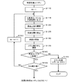
仮置き処理ルーチンが開始されると、CPU81は、まず、仮置き面71の上方へ実装ヘッド24が配置されるようX軸スライダ26及びY軸スライダ30を制御する(ステップS205)。続いて、CPU81は、RAM83のカウンタの変数Nに値1をセットする(ステップS210)。続いて、CPU81は、実装ヘッド24を回転させてN番目のノズル40を作動位置に配置する(ステップS215)。続いて、CPU81は、発光部付き部品660の仮置き動作を実行する(ステップS220)。すなわち、CPU81は、N番目のノズル40に吸着されている発光部付き部品660が仮置き面71のN番目の仮置きエリア74の上方位置に配置されるようX軸スライダ26及びY軸スライダ30を制御する。本実施形態では、4つの仮置きエリア74の左から順に1番目、2番目と数えるものとする。その後、CPU81は、その発光部付き部品660をN番目の仮置きエリア74に載置するようN番目のノズル40を下降させ、N番目のノズル40に正圧を供給する。それと共に、CPU81は、N番目の仮置きエリア74の穴73に負圧が供給されるよう切替弁76を制御する。その後、CPU81は、N番目のノズル40が上方位置に上昇するようZ軸モータ45を制御する。続いて、CPU81は、N番目の仮置きエリア74の穴73の圧力がしきい値未満か否かを判定する(ステップS225)。ここで、しきい値は、負圧が供給された穴73が発光部付き部品660によって覆われている場合には穴73の圧力値がしきい値未満になり、穴73が発光部付き部品660によって覆われていない場合には穴の負圧がしきい値以上となるように設定されている。そのため、ステップS225で肯定判定されたということは、発光部付き部品660が穴73を覆うように仮置きエリア74に仮置きされたことになり、否定判定されたということは、発光部付き部品660が仮置きエリア74に仮置きされなかったということになる。
When the temporary placement processing routine is started, the
そして、ステップS225でN番目の仮置きエリア74の穴73の圧力がしきい値未満でなかったならば、CPU81は、N番目のノズル40の先端付近を側方カメラ44に撮像させる(ステップS240)。すなわち、CPU81は、N番目のノズル40が撮影位置に配置されるよう実装ヘッド24を制御した後、その位置で側方カメラ44にN番目のノズル40の先端付近を撮像させ、その画像データをRAM83に取り込む。続いて、CPU81は、N番目のノズル40の先端に発光部付き部品660が吸着しているか否かを判定する(ステップS245)。
If the pressure in the
そして、N番目のノズル40の先端に発光部付き部品660が吸着していたならば、CPU81は、エラーコードE2の表示を含むエラー処理を実行し(ステップS250)、部品実装プログラムを終了する。ステップS250のエラー処理では、CPU81は、部品実装装置11の図示しないディスプレイにエラーコードE2を表示すると共に、警告音を鳴らし、警告ランプを点灯させる。エラーコードE2は、仮置きエリア74への部品の仮置きに失敗し、且つ、ノズル40がその部品を吸着したままであることを表す。そのため、エラーコードE2を見た作業者は、仮置きに失敗した部品がノズル40に吸着されていることを容易に知ることができる。一方、ステップS245でN番目のノズル40の先端に発光部付き部品660が吸着していなかったならば、CPU81は、エラーコードE3の表示を含むエラー処理を実行し(ステップS255)、部品実装プログラムを終了する。ステップS255のエラー処理では、CPU81は、部品実装装置11の図示しないディスプレイにエラーコードE3を表示すると共に、警告音を鳴らし、警告ランプを点灯させる。エラーコードE3は、仮置きエリア74への部品の仮置きに失敗し、且つ、ノズル40がその部品を吸着していないことを表す。そのため、エラーコードE3を見た作業者は、リールユニット56から仮置き台70までの間か仮置き台70の周辺に部品が落下していると予測することができる。
If the light emitting part-equipped
一方、ステップS225でN番目の仮置きエリア74の穴73の圧力がしきい値未満だったならば、CPU81は、変数Nが最大値か否かを判定する(ステップS230)。そして、変数Nが最大値でなかったならば、CPU81は、変数Nを1インクリメントし(ステップS235)、ステップS215に戻る。一方、ステップS230で変数Nが最大値だったならば、すべての仮置きエリア74に発光部付き部品660が仮置きされていることになるため、CPU81は再吸着・実装処理ルーチン(ステップS300)へ進む。
On the other hand, if the pressure in the
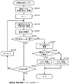
再吸着・実装処理ルーチンが開始されると、CPU81は、まず、RAM83のカウンタの変数Nに値1をセットする(ステップS310)。続いて、CPU81は、N番目のノズル40を作動位置に配置する(ステップS315)。続いて、CPU81は、図11に示すように、N番目の仮置きエリア74に仮置きされた発光部付き部品660の上面をマークカメラ34に撮像させる(ステップS320)。すなわち、CPU81は、マークカメラ34がN番目の仮置きエリア74に仮置きされた発光部付き部品660の上方に来るようにX軸スライダ26及びY軸スライダ30を制御した後、その位置でマークカメラ34に発光部付き部品660のLED660aを含む上面を撮像させ、その画像データをRAM83に取り込む。続いて、CPU81は、発光部付き部品660の吸着位置を算出する(ステップS325)。ここでは、CPU81は、取り込んだ画像データから発光部付き部品660の外側の輪郭とLED660aの中心位置660cを算出し、それらから吸着位置660bを算出する。この処理は、ステップS125と同様であるが、仮置き面71は平坦性が良いため、発光部付き部品660は水平に保持されている。そのため、算出した吸着位置660bは、予め定めた特定の位置と精度よく一致する。
When the re-adsorption / mounting process routine is started, the
続いて、CPU81は、N番目の仮置きエリア74に仮置きされた発光部付き部品660をN番目のノズル40に再吸着させる(ステップS330)。すなわち、CPU81は、N番目の仮置きエリア74に仮置きされた発光部付き部品660の吸着位置660bの真上にN番目のノズル40が来るようにX軸スライダ26及びY軸スライダ30を制御した後、N番目のノズル40の先端がその吸着位置660bに接触するようにZ軸モータ45を制御する。それと共に、CPU81は、N番目のノズル40に負圧を供給してノズル40に発光部付き部品660を吸着させる。その際、CPU81は、N番目の仮置きエリア74の穴73に正圧が供給されるよう切替弁76を制御する。これにより、発光部付き部品660は仮置きエリア74から離れやすくなる。その後、CPU81は、N番目のノズル40が上方位置に上昇するようZ軸モータ45を制御する。続いて、CPU81は、N番目の仮置きエリア74の穴73に再度負圧が供給されるよう切替弁76を制御し(ステップS335)、その穴73の圧力がしきい値以上か否かを判定する(ステップS340)。ここで、しきい値は、上述したステップS225のしきい値と同様に設定すればよい。
Subsequently, the
そして、ステップS340でN番目の仮置きエリア74の穴73の圧力がしきい値以上でなかったならば、CPU81は、エラーコードE4の表示を含むエラー処理を実行し(ステップS365)、部品実装プログラムを終了する。ステップS365のエラー処理では、CPU81は、部品実装装置11の図示しないディスプレイにエラーコードE4を表示すると共に、警告音を鳴らし、警告ランプを点灯させる。エラーコードE4は、仮置きエリア74からの部品の再吸着が失敗して仮置きエリア74に部品が残ったままであることを表す。そのため、エラーコードE4を見た作業者は、再吸着に失敗した部品が仮置き面71に残っていることを容易に知ることができる。
If the pressure in the
一方、ステップS340でN番目の仮置きエリア74の穴73の圧力がしきい値以上だったならば、CPU81は、N番目のノズル40の先端付近を側方カメラ44に撮像させる(ステップS345)。すなわち、CPU81は、N番目のノズル40が撮影位置に配置されるよう実装ヘッド24を制御した後、その位置で側方カメラ44にN番目のノズル40の先端付近を撮像させ、その画像データをRAM83に取り込む。続いて、CPU81は、N番目のノズル40の先端に発光部付き部品660が吸着しているか否かを判定する(ステップS350)。
On the other hand, if the pressure in the
そして、N番目のノズル40の先端に発光部付き部品660が吸着していなかったならば、CPU81は、エラーコードE5の表示を含むエラー処理を実行し(ステップS370)、部品実装プログラムを終了する。ステップS370のエラー処理では、CPU81は、部品実装装置11の図示しないディスプレイにエラーコードE5を表示すると共に、警告音を鳴らし、警告ランプを点灯させる。エラーコードE5は、ノズル40が仮置きエリア74から部品を一旦再吸着したものの途中でノズル40から部品が外れたことをことを表す。そのため、エラーコードE5を見た作業者は、仮置き面71の周辺に部品が残っていることを容易に知ることができる。
If the
一方、ステップS350でN番目のノズル40の先端に発光部付き部品660が吸着していたならば、CPU81は、変数Nが最大値(ここでは値4)か否かを判定し(ステップS355)、変数Nが最大値でなかったならば変数Nの値を1インクリメントし(ステップS360)、再びステップ315へ戻る。一方、ステップS350で変数Nが最大値だったならば、すべてのノズル40に発光部付き部品660が再吸着されていることになるため、実装処理理ルーチン(ステップS375)を実行し、この部品実装プログラムを終了する。実装処理ルーチンでは、CPU81は、基板12上へ実装ヘッド24を移動し、生産ジョブデータで指定された位置に各発光部付き部品660のLED660aが配置されるようX軸スライダ26,Y軸スライダ30及びZ軸モータ45を制御すると共にノズル40の圧力を制御する。
On the other hand, if the light emitting part-equipped
なお、エラーが発生した場合には、作業者は不具合の生じた原因を取り除いたあと部品実装プログラムを再スタートさせる。これにより、CPU81は中断されていた部品実装プログラムを再開する。
When an error occurs, the operator removes the cause of the failure and restarts the component mounting program. As a result, the
ここで、本実施形態の構成要素と本発明の構成要素との対応関係を明らかにする。本実施形態のリールユニット56が本発明の部品供給手段に相当し、実装ヘッド24が部品吸着手段に相当し、X軸スライダ26,Y軸スライダ30及びZ軸モータ45が移動手段に相当し、支持板20及び支持ピン23が基板保持手段に相当し、切替弁76、真空ポンプ77及びエアコンプレッサ78が圧力調節手段に相当し、圧力センサ75が圧力検出手段に相当し、制御装置80が制御手段に相当する。また、側方カメラ44が側方撮像手段に相当し、マークカメラ34が上面撮像手段に相当する。
Here, the correspondence between the components of the present embodiment and the components of the present invention will be clarified. The
以上詳述した本実施形態の部品実装装置11によれば、発光部付き部品660が仮置き面71の仮置きエリア74に仮置きされるように制御した後、穴73に負圧を供給した状態で穴73の圧力状態に基づいて発光部付き部品660が実際に仮置きされたか否かを判定し、該判定の結果に応じた処理を実行する。このように仮置きエリア74に設けられた穴73の圧力状態に基づいて発光部付き部品660が実際に仮置きされたか否かを判定するため、仮置き面71上を撮像してその撮像した画像を解析して発光部付き部品660の有無をチェックする場合に比べて、その判定を迅速に行うことができる。したがって、スループットが向上する。
According to the
また、リールユニット56が発光部付き部品660を供給する場合、その発光部付き部品660はテープ60を用いて供給されるが、テープ60は平坦性が良くないため、発光部付き部品660ががたつきやすい。そのため、リールユニット56によって供給された発光部付き部品660を実装ヘッド24のノズル40が吸着するとき、予め定めた特定の吸着位置660bを精度よく吸着することは困難である。しかし、本実施形態では、仮置き面71が平坦面であるため、この仮置き面71に載置された発光部付き部品660を実装ヘッド24のノズル40が再吸着する際には、特定の吸着位置660bを精度よく吸着することができる。
In addition, when the
更に、実際には仮置き面71に発光部付き部品660が仮置きされていなかった場合、ノズル40にその発光部付き部品660が吸着されたままなのか否かをエラーコードE2,E3によって作業者に知らせるため、作業者は仮置きされなかった発光部付き部品660を容易に探すことができる。
Further, in practice, when the
更にまた、CPU81は、仮置き面71の仮置きエリア74に発光部付き部品660が実際に仮置きされたことを確認したあと、発光部付き部品660の上面の撮像を含む再吸着・実装処理ルーチンを実行する。そのため、実際には発光部付き部品660が仮置きされていない場合にこうした再吸着・実装処理ルーチンを無駄に実行してしまうのを回避することができる。
Furthermore, the
そしてまた、CPU81は、発光部付き部品660が実装ヘッド24のノズル40に再吸着される際、穴73の圧力を正圧になるよう切替弁76を制御する。そのため、ノズル40は発光部付き部品660をスムーズに再吸着することができる。
Further, the
なお、本発明は上述した実施形態に何ら限定されることはなく、本発明の技術的範囲に属する限り種々の態様で実施し得ることはいうまでもない。 It should be noted that the present invention is not limited to the above-described embodiment, and it goes without saying that the present invention can be implemented in various modes as long as it belongs to the technical scope of the present invention.
例えば、上述した実施形態の仮置き処理ルーチン(図8)において、CPU81は、ステップS225で否定判定したならば、ステップS240〜S255を実行する代わりに、単に仮置きに失敗した旨のエラー処理を実行してもよい。こうすれば、画像解析を行うことなくエラー処理を実行するため、仮置きに失敗したことを迅速に作業者に報知することができ、スループットが一層向上する。
For example, in the temporary placement processing routine (FIG. 8) of the above-described embodiment, if the
上述した実施形態において、実装ヘッド24は4本のノズル40を備えたものとしたが、ノズル40の本数は特にいくつでも構わない。例えば、実装ヘッド24は、1本のノズル40を備えたものとしてもよいし、8本とか12本のノズル40を備えたものとしてもよい。また、例えば8本のノズル40を備えた実装ヘッド24を用い、上述した実施形態のように4つの仮置きエリア74が設けられた仮置き面71を用いる場合には、8本のノズル40のうち4本のみを用いるようにしてもよい。
In the above-described embodiment, the mounting
上述した実施形態では、仮置き面71の4つの穴73のそれぞれに対して真空ポンプ77、エアコンプレッサ78を設けたが、真空ポンプ77やエアコンプレッサ78を1つに集約してもよい。
In the embodiment described above, the
上述した実施形態では、仮置き面71の4つの穴73にエアコンプレッサ78を接続したが、エアコンプレッサ78を設けず大気に連通するようにしてもよい。この場合、穴73に正圧を供給する代わりに、大気圧を供給することになる。
In the above-described embodiment, the
上述した実施形態では、上面にLED660aが取り付けられた発光部付き部品660を例示し、LED660aの中心位置660cから所定の吸着位置660bを求めるようにしたが、LED660aの代わりに別のものを目印として上面に付してもよい。例えば、ダイオードやコンデンサ等の極性を有する部品の場合、部品の上面に極性の方向を示すマーク(例えば「+」の刻印)を付け、このマークの位置から所定の吸着位置を求めるようにしてもよい。
In the embodiment described above, the light emitting part-equipped
上述した実施形態の仮置き処理ルーチンのステップS250では、CPU81はエラーコードE2の表示を含むエラー処理を実行することとしたが、ノズル40に発光部付き部品660が吸着された状態であるため、ステップS220に戻り、再度部品の仮置き動作を実行してもよい。
In step S250 of the temporary placement processing routine of the above-described embodiment, the
上述した実施形態では、部品供給装置としてリールユニット56を例示したが、リールユニット56の代わりにトレイユニットを用いてもよい。
In the embodiment described above, the
上述した実施形態では、仮置きエリア74に仮置きされた発光部付き部品660を再吸着する際に予め定めた特定の吸着位置660bを再吸着するようにしたが、特定の吸着位置660bではなく予め定めた設計値(座標位置)を再吸着するようにしてもよい。このようにしても、LED660aが基板12上の所定の位置に配置されるよう発光部付き部品660を実装することができる。
In the above-described embodiment, the
本発明は、基板に電子部品を実装する部品実装装置に利用可能である。 The present invention is applicable to a component mounting apparatus for mounting electronic components on a substrate.
10 実装システム、11 部品実装装置、12 基板、18 搬送部、20 支持板、21 採取部、22 コンベアベルト、23 支持ピン、24 実装ヘッド、26 X軸スライダ、28 ガイドレール、30 Y軸スライダ、32 ガイドレール、34 マークカメラ、40 ノズル、42 ノズル保持体、44 側方カメラ、45 Z軸モータ、56 リールユニット、57 リール、58 フィーダ、60 テープ、62 収容部、64 フィルム、66 部品、67 スプロケット穴、70 仮置き台、71 仮置き面、72 仮置き台マーク、73 圧力穴、74 仮置きエリア、75 圧力センサ、76 切替弁、77 真空ポンプ、78 エアコンプレッサ、80 制御装置、81 CPU、82 ROM、83 RAM、84 HDD、85 入出力インタフェース、86 バス、90 管理コンピュータ、97 入力デバイス、98 ディスプレイ、660 発光部付き部品、660a LED、660b 吸着位置、660c 中心位置。
DESCRIPTION OF
Claims (5)
前記部品を吸着可能な部品吸着手段と、
前記部品吸着手段を移動させる移動手段と、
前記部品が実装される基板を保持する基板保持手段と、
所定位置に穴を有し、前記部品を前記所定位置に仮置きするための仮置き面と、
前記穴に少なくとも負圧を供給可能な圧力調節手段と、
前記穴の圧力を検出する圧力検出手段と、
前記部品吸着手段に吸着された部品を側方から撮像可能な側方撮像手段と、
前記部品供給手段によって供給された部品を前記部品吸着手段が吸着した後前記基板上に実装する前に前記部品が前記所定位置に仮置きされるよう前記部品吸着手段及び前記移動手段を制御する制御手段と、
を備え、
前記制御手段は、前記部品が前記所定位置に仮置きされるよう制御した後、前記穴に負圧を供給した状態で前記穴の圧力状態に基づいて前記所定位置に前記部品が実際に仮置きされたか否かを判定し、該判定の結果に応じた処理を実行するものであり、
前記制御手段は、前記判定の結果が否定判定ならば、前記側方撮像手段に前記部品吸着手段を撮像させ、該撮像された画像に基づいて前記部品吸着手段が前記部品を吸着しているか否かを判定し、その判定結果を作業者に報知して前記一連の処理を中止する、
部品実装装置。 Parts supply means for supplying parts;
Component adsorbing means capable of adsorbing the component;
Moving means for moving the component suction means;
Board holding means for holding a board on which the component is mounted;
Having a hole at a predetermined position, and a temporary placement surface for temporarily placing the component at the predetermined position;
Pressure adjusting means capable of supplying at least negative pressure to the hole;
Pressure detecting means for detecting the pressure of the hole;
Side imaging means capable of imaging the part adsorbed by the parts adsorption means from the side;
Control for controlling the component suction unit and the moving unit so that the component is temporarily placed at the predetermined position after the component suction unit sucks the component supplied by the component supply unit and before the component is mounted on the substrate. Means,
With
The control means controls the part to be temporarily placed at the predetermined position, and then the part is actually temporarily placed at the predetermined position based on the pressure state of the hole with negative pressure supplied to the hole. It is determined whether or not, and processing according to the result of the determination is performed ,
If the result of the determination is negative, the control means causes the side imaging means to image the component suction means, and whether or not the component suction means suctions the component based on the captured image. Determine whether or not, and notify the operator of the determination result to stop the series of processes,
Component mounting equipment.
前記仮置き面に仮置きされた前記部品の上面を撮像可能な上面撮像手段
を備え、
前記制御手段は、前記判定の結果が肯定判定ならば、前記仮置きされた部品の上面を前記上面撮像手段に撮像させ、該撮像された画像に基づいて前記部品の位置を特定し、前記部品吸着手段にて前記部品を再吸着し、前記特定した前記部品の位置に基づき前記部品が前記基板上の実装位置に実装されるよう前記部品吸着手段及び前記移動手段を制御するという一連の処理を実行し、一方、前記判定の結果が否定判定ならば、前記一連の処理を中止する、
部品実装装置。 The component mounting apparatus according to claim 1 ,
Upper surface imaging means capable of imaging the upper surface of the component temporarily placed on the temporary placement surface;
If the result of the determination is affirmative, the control means causes the upper surface imaging means to image the upper surface of the temporarily placed component, specifies the position of the component based on the captured image, and A series of processes of re-sucking the component by the suction unit and controlling the component suction unit and the moving unit so that the component is mounted at the mounting position on the substrate based on the specified position of the component. On the other hand, if the result of the determination is negative, the series of processing is stopped.
Component mounting equipment.
前記部品を吸着可能な部品吸着手段と、
前記部品吸着手段を移動させる移動手段と、
前記部品が実装される基板を保持する基板保持手段と、
所定位置に穴を有し、前記部品を前記所定位置に仮置きするための仮置き面と、
前記穴に少なくとも負圧を供給可能な圧力調節手段と、
前記穴の圧力を検出する圧力検出手段と、
前記仮置き面に仮置きされた前記部品の上面を撮像可能な上面撮像手段と、
前記部品供給手段によって供給された部品を前記部品吸着手段が吸着した後前記基板上に実装する前に前記部品が前記所定位置に仮置きされるよう前記部品吸着手段及び前記移動手段を制御する制御手段と、
を備え、
前記制御手段は、前記部品が前記所定位置に仮置きされるよう制御した後、前記穴に負圧を供給した状態で前記穴の圧力状態に基づいて前記所定位置に前記部品が実際に仮置きされたか否かを判定し、該判定の結果に応じた処理を実行するものであり、
前記制御手段は、前記判定の結果が肯定判定ならば、前記仮置きされた部品の上面を前記上面撮像手段に撮像させ、該撮像された画像に基づいて前記部品の位置を特定し、前記部品吸着手段にて前記部品を再吸着し、前記特定した前記部品の位置に基づき前記部品が前記基板上の実装位置に実装されるよう前記部品吸着手段及び前記移動手段を制御するという一連の処理を実行し、一方、前記判定の結果が否定判定ならば、前記一連の処理を中止し、
前記制御手段は、前記部品が前記部品吸着手段に再吸着されるよう制御した後、前記穴に負圧を供給した状態で前記穴の圧力状態に基づいて前記部品が実際に前記部品吸着手段に再吸着されたか否かの第2判定を行い、該第2判定の結果が肯定判定ならば、前記一連の処理を続行し、前記第2判定の結果が否定判定ならば、前記一連の処理を中断する、
部品実装装置。 Parts supply means for supplying parts;
Component adsorbing means capable of adsorbing the component;
Moving means for moving the component suction means;
Board holding means for holding a board on which the component is mounted;
Having a hole at a predetermined position, and a temporary placement surface for temporarily placing the component at the predetermined position;
Pressure adjusting means capable of supplying at least negative pressure to the hole;
Pressure detecting means for detecting the pressure of the hole;
Upper surface imaging means capable of imaging the upper surface of the component temporarily placed on the temporary placement surface;
Control for controlling the component suction unit and the moving unit so that the component is temporarily placed at the predetermined position after the component suction unit sucks the component supplied by the component supply unit and before the component is mounted on the substrate. Means,
With
The control means controls the part to be temporarily placed at the predetermined position, and then the part is actually temporarily placed at the predetermined position based on the pressure state of the hole with negative pressure supplied to the hole. It is determined whether or not, and processing according to the result of the determination is performed ,
If the result of the determination is affirmative, the control means causes the upper surface imaging means to image the upper surface of the temporarily placed component, specifies the position of the component based on the captured image, and A series of processes of re-sucking the component by the suction unit and controlling the component suction unit and the moving unit so that the component is mounted at the mounting position on the substrate based on the specified position of the component. On the other hand, if the result of the determination is negative, the series of processing is stopped,
The control unit controls the component to be re-adsorbed to the component adsorbing unit, and then supplies the component to the component adsorbing unit based on the pressure state of the hole with negative pressure supplied to the hole. If the second determination result is affirmative determination, the series of processes is continued. If the second determination result is negative, the series of processes is performed. Interrupt,
Component mounting equipment.
請求項2又は3に記載の部品実装装置。 The control means controls the pressure adjusting means so that the pressure of the hole becomes an atmospheric pressure or a positive pressure when the parts are re-sucked by the parts suction means.
The component mounting apparatus according to claim 2 or 3 .
請求項1〜4のいずれか1項に記載の部品実装装置。 The temporary placement surface is a flat surface,
The component mounting apparatus of any one of Claims 1-4 .
Applications Claiming Priority (1)
| Application Number | Priority Date | Filing Date | Title |
|---|---|---|---|
| PCT/JP2014/073380 WO2016035195A1 (en) | 2014-09-04 | 2014-09-04 | Component mounting device |
Publications (2)
| Publication Number | Publication Date |
|---|---|
| JPWO2016035195A1 JPWO2016035195A1 (en) | 2017-06-15 |
| JP6412944B2 true JP6412944B2 (en) | 2018-10-24 |
Family
ID=55439294
Family Applications (1)
| Application Number | Title | Priority Date | Filing Date |
|---|---|---|---|
| JP2016546267A Active JP6412944B2 (en) | 2014-09-04 | 2014-09-04 | Component mounting equipment |
Country Status (5)
| Country | Link |
|---|---|
| US (1) | US10349570B2 (en) |
| EP (1) | EP3197255B1 (en) |
| JP (1) | JP6412944B2 (en) |
| CN (1) | CN106605459B (en) |
| WO (1) | WO2016035195A1 (en) |
Families Citing this family (7)
| Publication number | Priority date | Publication date | Assignee | Title |
|---|---|---|---|---|
| US10349570B2 (en) * | 2014-09-04 | 2019-07-09 | Fuji Corporation | Component mounter |
| JP6679598B2 (en) * | 2015-09-09 | 2020-04-15 | 株式会社Fuji | Separate type reel holding device |
| EP3651561B1 (en) * | 2017-07-04 | 2022-02-09 | Fuji Corporation | Component mounting device |
| DE102017116042B4 (en) * | 2017-07-17 | 2019-03-21 | Asm Assembly Systems Gmbh & Co. Kg | Method and placement machine for equipping component carriers with electronic components |
| JP6931771B2 (en) * | 2017-09-14 | 2021-09-08 | パナソニックIpマネジメント株式会社 | Component mounting device and component mounting method |
| JP7102177B2 (en) * | 2018-03-15 | 2022-07-19 | ヤマハ発動機株式会社 | Board detection device and board processing device |
| WO2020003424A1 (en) * | 2018-06-27 | 2020-01-02 | ヤマハ発動機株式会社 | Component feeding device |
Family Cites Families (22)
| Publication number | Priority date | Publication date | Assignee | Title |
|---|---|---|---|---|
| JP2639968B2 (en) | 1988-06-16 | 1997-08-13 | ティーディーケイ株式会社 | Electronic component mounting machine |
| CA1320005C (en) | 1988-06-16 | 1993-07-06 | Kotaro Harigane | Electronic component mounting apparatus |
| JPH05327286A (en) * | 1992-05-25 | 1993-12-10 | Sony Corp | Electronic component inserting apparatus |
| JP3261770B2 (en) * | 1992-11-19 | 2002-03-04 | 松下電器産業株式会社 | Component mounting device |
| SG52900A1 (en) * | 1996-01-08 | 1998-09-28 | Matsushita Electric Ind Co Ltd | Mounting apparatus of electronic components and mounting methods of the same |
| JP3861415B2 (en) * | 1997-11-11 | 2006-12-20 | ソニー株式会社 | Electronic component mounting equipment |
| JP4170475B2 (en) * | 1998-11-12 | 2008-10-22 | 松下電器産業株式会社 | Electronic component mounting apparatus and mounting method |
| JP2001237596A (en) * | 2000-02-24 | 2001-08-31 | Matsushita Electric Ind Co Ltd | Method and device for mounting electronic part |
| JP4222741B2 (en) * | 2001-04-06 | 2009-02-12 | 芝浦メカトロニクス株式会社 | Component mounting apparatus and component mounting method |
| JP4078210B2 (en) | 2003-01-09 | 2008-04-23 | 富士機械製造株式会社 | Electronic circuit component mounting machine and electronic circuit component mounting method |
| JP4334892B2 (en) * | 2003-03-20 | 2009-09-30 | パナソニック株式会社 | Component mounting method |
| JP4044017B2 (en) * | 2003-04-22 | 2008-02-06 | 松下電器産業株式会社 | Component mounting apparatus and method |
| JP4587745B2 (en) | 2003-09-01 | 2010-11-24 | Juki株式会社 | Electronic component suction position correction device for electronic component mounting machine |
| JP2007189142A (en) * | 2006-01-16 | 2007-07-26 | I-Pulse Co Ltd | Sticking method of flexible substrate, and equipment thereof |
| JP4974864B2 (en) | 2007-12-03 | 2012-07-11 | ヤマハ発動機株式会社 | Component adsorption device and mounting machine |
| JP2009246070A (en) * | 2008-03-31 | 2009-10-22 | Nec Saitama Ltd | Positioning device, contour regulating jig and positioning method |
| TW201221453A (en) * | 2010-11-16 | 2012-06-01 | Hon Hai Prec Ind Co Ltd | Surface mounting machine nozzle |
| JP5024494B1 (en) * | 2012-03-05 | 2012-09-12 | 富士ゼロックス株式会社 | Method for manufacturing mounting device and substrate device |
| CN104838738B (en) | 2012-12-07 | 2017-10-27 | 富士机械制造株式会社 | Installation data generating means, generation method and substrate production system |
| DE102013102046A1 (en) * | 2013-03-01 | 2014-09-04 | Asm Assembly Systems Gmbh & Co. Kg | Device for supplying electronic components to surface mounted device machine for mounting printed circuit boards with components, has interface for transferring position and orientation of retained component detected by sensor unit to head |
| WO2014196002A1 (en) * | 2013-06-03 | 2014-12-11 | 富士機械製造株式会社 | Nozzle management system |
| US10349570B2 (en) * | 2014-09-04 | 2019-07-09 | Fuji Corporation | Component mounter |
-
2014
- 2014-09-04 US US15/508,521 patent/US10349570B2/en active Active
- 2014-09-04 JP JP2016546267A patent/JP6412944B2/en active Active
- 2014-09-04 WO PCT/JP2014/073380 patent/WO2016035195A1/en active Application Filing
- 2014-09-04 CN CN201480081606.0A patent/CN106605459B/en active Active
- 2014-09-04 EP EP14901354.2A patent/EP3197255B1/en active Active
Also Published As
| Publication number | Publication date |
|---|---|
| WO2016035195A1 (en) | 2016-03-10 |
| JPWO2016035195A1 (en) | 2017-06-15 |
| US20170280598A1 (en) | 2017-09-28 |
| US10349570B2 (en) | 2019-07-09 |
| EP3197255A1 (en) | 2017-07-26 |
| EP3197255B1 (en) | 2019-10-23 |
| CN106605459B (en) | 2019-12-24 |
| CN106605459A (en) | 2017-04-26 |
| EP3197255A4 (en) | 2017-09-06 |
Similar Documents
| Publication | Publication Date | Title |
|---|---|---|
| JP6412944B2 (en) | Component mounting equipment | |
| JP6131045B2 (en) | Electronic component mounting apparatus and electronic component mounting method | |
| JP6309830B2 (en) | Component mounting device | |
| JP6293899B2 (en) | Mounting device | |
| JP6231791B2 (en) | Mounting device | |
| CN107852849B (en) | Component mounting machine | |
| JP6577475B2 (en) | Component mounting equipment | |
| JP5925524B2 (en) | Electronic component supply device and electronic component mounting device | |
| JP6828223B2 (en) | Mounting device | |
| JP6212263B2 (en) | Component mounting apparatus, component mounting method and program thereof | |
| JP6624976B2 (en) | Component mounting equipment | |
| JP6448766B2 (en) | Mounting apparatus and mounting method | |
| JP6673900B2 (en) | Mounting device and mounting method | |
| JP2003101292A (en) | Method and machine for mounting component | |
| JP6789561B2 (en) | Component mounting device | |
| JP5980933B2 (en) | Control system and control method for component mounter | |
| JP5467370B2 (en) | Component mounting method | |
| JP6318367B2 (en) | Component mounting method and component mounting apparatus | |
| JP7425060B2 (en) | component mounting machine | |
| JP7124126B2 (en) | Component mounter | |
| JP6706687B2 (en) | Board-to-board working machine | |
| JP2023007881A (en) | Component mounting system and component mounting method | |
| EP4007473A1 (en) | Mounting device and method for controlling mounting device |
Legal Events
| Date | Code | Title | Description |
|---|---|---|---|
| A621 | Written request for application examination |
Free format text: JAPANESE INTERMEDIATE CODE: A621 Effective date: 20170707 |
|
| A131 | Notification of reasons for refusal |
Free format text: JAPANESE INTERMEDIATE CODE: A131 Effective date: 20180710 |
|
| A521 | Request for written amendment filed |
Free format text: JAPANESE INTERMEDIATE CODE: A523 Effective date: 20180903 |
|
| TRDD | Decision of grant or rejection written | ||
| A01 | Written decision to grant a patent or to grant a registration (utility model) |
Free format text: JAPANESE INTERMEDIATE CODE: A01 Effective date: 20180918 |
|
| A61 | First payment of annual fees (during grant procedure) |
Free format text: JAPANESE INTERMEDIATE CODE: A61 Effective date: 20181001 |
|
| R150 | Certificate of patent or registration of utility model |
Ref document number: 6412944 Country of ref document: JP Free format text: JAPANESE INTERMEDIATE CODE: R150 |
|
| R250 | Receipt of annual fees |
Free format text: JAPANESE INTERMEDIATE CODE: R250 |
|
| R250 | Receipt of annual fees |
Free format text: JAPANESE INTERMEDIATE CODE: R250 |
|
| R250 | Receipt of annual fees |
Free format text: JAPANESE INTERMEDIATE CODE: R250 |