JP6364475B2 - 超音波溶接のための装置 - Google Patents
超音波溶接のための装置 Download PDFInfo
- Publication number
- JP6364475B2 JP6364475B2 JP2016506826A JP2016506826A JP6364475B2 JP 6364475 B2 JP6364475 B2 JP 6364475B2 JP 2016506826 A JP2016506826 A JP 2016506826A JP 2016506826 A JP2016506826 A JP 2016506826A JP 6364475 B2 JP6364475 B2 JP 6364475B2
- Authority
- JP
- Japan
- Prior art keywords
- sonotrode
- converters
- reaction force
- longitudinal direction
- action
- Prior art date
- Legal status (The legal status is an assumption and is not a legal conclusion. Google has not performed a legal analysis and makes no representation as to the accuracy of the status listed.)
- Expired - Fee Related
Links
Images

Classifications
-
- B—PERFORMING OPERATIONS; TRANSPORTING
- B65—CONVEYING; PACKING; STORING; HANDLING THIN OR FILAMENTARY MATERIAL
- B65B—MACHINES, APPARATUS OR DEVICES FOR, OR METHODS OF, PACKAGING ARTICLES OR MATERIALS; UNPACKING
- B65B51/00—Devices for, or methods of, sealing or securing package folds or closures; Devices for gathering or twisting wrappers, or necks of bags
- B65B51/10—Applying or generating heat or pressure or combinations thereof
- B65B51/22—Applying or generating heat or pressure or combinations thereof by friction or ultrasonic or high-frequency electrical means, i.e. by friction or ultrasonic or induction welding
- B65B51/225—Applying or generating heat or pressure or combinations thereof by friction or ultrasonic or high-frequency electrical means, i.e. by friction or ultrasonic or induction welding by ultrasonic welding
-
- B—PERFORMING OPERATIONS; TRANSPORTING
- B06—GENERATING OR TRANSMITTING MECHANICAL VIBRATIONS IN GENERAL
- B06B—METHODS OR APPARATUS FOR GENERATING OR TRANSMITTING MECHANICAL VIBRATIONS OF INFRASONIC, SONIC, OR ULTRASONIC FREQUENCY, e.g. FOR PERFORMING MECHANICAL WORK IN GENERAL
- B06B3/00—Methods or apparatus specially adapted for transmitting mechanical vibrations of infrasonic, sonic, or ultrasonic frequency
-
- B—PERFORMING OPERATIONS; TRANSPORTING
- B29—WORKING OF PLASTICS; WORKING OF SUBSTANCES IN A PLASTIC STATE IN GENERAL
- B29C—SHAPING OR JOINING OF PLASTICS; SHAPING OF MATERIAL IN A PLASTIC STATE, NOT OTHERWISE PROVIDED FOR; AFTER-TREATMENT OF THE SHAPED PRODUCTS, e.g. REPAIRING
- B29C65/00—Joining or sealing of preformed parts, e.g. welding of plastics materials; Apparatus therefor
- B29C65/02—Joining or sealing of preformed parts, e.g. welding of plastics materials; Apparatus therefor by heating, with or without pressure
- B29C65/08—Joining or sealing of preformed parts, e.g. welding of plastics materials; Apparatus therefor by heating, with or without pressure using ultrasonic vibrations
-
- B—PERFORMING OPERATIONS; TRANSPORTING
- B29—WORKING OF PLASTICS; WORKING OF SUBSTANCES IN A PLASTIC STATE IN GENERAL
- B29C—SHAPING OR JOINING OF PLASTICS; SHAPING OF MATERIAL IN A PLASTIC STATE, NOT OTHERWISE PROVIDED FOR; AFTER-TREATMENT OF THE SHAPED PRODUCTS, e.g. REPAIRING
- B29C66/00—General aspects of processes or apparatus for joining preformed parts
- B29C66/80—General aspects of machine operations or constructions and parts thereof
- B29C66/81—General aspects of the pressing elements, i.e. the elements applying pressure on the parts to be joined in the area to be joined, e.g. the welding jaws or clamps
- B29C66/814—General aspects of the pressing elements, i.e. the elements applying pressure on the parts to be joined in the area to be joined, e.g. the welding jaws or clamps characterised by the design of the pressing elements, e.g. of the welding jaws or clamps
- B29C66/8141—General aspects of the pressing elements, i.e. the elements applying pressure on the parts to be joined in the area to be joined, e.g. the welding jaws or clamps characterised by the design of the pressing elements, e.g. of the welding jaws or clamps characterised by the surface geometry of the part of the pressing elements, e.g. welding jaws or clamps, coming into contact with the parts to be joined
- B29C66/81431—General aspects of the pressing elements, i.e. the elements applying pressure on the parts to be joined in the area to be joined, e.g. the welding jaws or clamps characterised by the design of the pressing elements, e.g. of the welding jaws or clamps characterised by the surface geometry of the part of the pressing elements, e.g. welding jaws or clamps, coming into contact with the parts to be joined comprising a single cavity, e.g. a groove
-
- B—PERFORMING OPERATIONS; TRANSPORTING
- B29—WORKING OF PLASTICS; WORKING OF SUBSTANCES IN A PLASTIC STATE IN GENERAL
- B29C—SHAPING OR JOINING OF PLASTICS; SHAPING OF MATERIAL IN A PLASTIC STATE, NOT OTHERWISE PROVIDED FOR; AFTER-TREATMENT OF THE SHAPED PRODUCTS, e.g. REPAIRING
- B29C66/00—General aspects of processes or apparatus for joining preformed parts
- B29C66/80—General aspects of machine operations or constructions and parts thereof
- B29C66/81—General aspects of the pressing elements, i.e. the elements applying pressure on the parts to be joined in the area to be joined, e.g. the welding jaws or clamps
- B29C66/814—General aspects of the pressing elements, i.e. the elements applying pressure on the parts to be joined in the area to be joined, e.g. the welding jaws or clamps characterised by the design of the pressing elements, e.g. of the welding jaws or clamps
- B29C66/8145—General aspects of the pressing elements, i.e. the elements applying pressure on the parts to be joined in the area to be joined, e.g. the welding jaws or clamps characterised by the design of the pressing elements, e.g. of the welding jaws or clamps characterised by the constructional aspects of the pressing elements, e.g. of the welding jaws or clamps
-
- B—PERFORMING OPERATIONS; TRANSPORTING
- B29—WORKING OF PLASTICS; WORKING OF SUBSTANCES IN A PLASTIC STATE IN GENERAL
- B29C—SHAPING OR JOINING OF PLASTICS; SHAPING OF MATERIAL IN A PLASTIC STATE, NOT OTHERWISE PROVIDED FOR; AFTER-TREATMENT OF THE SHAPED PRODUCTS, e.g. REPAIRING
- B29C66/00—General aspects of processes or apparatus for joining preformed parts
- B29C66/80—General aspects of machine operations or constructions and parts thereof
- B29C66/84—Specific machine types or machines suitable for specific applications
- B29C66/849—Packaging machines
-
- B—PERFORMING OPERATIONS; TRANSPORTING
- B29—WORKING OF PLASTICS; WORKING OF SUBSTANCES IN A PLASTIC STATE IN GENERAL
- B29C—SHAPING OR JOINING OF PLASTICS; SHAPING OF MATERIAL IN A PLASTIC STATE, NOT OTHERWISE PROVIDED FOR; AFTER-TREATMENT OF THE SHAPED PRODUCTS, e.g. REPAIRING
- B29C66/00—General aspects of processes or apparatus for joining preformed parts
- B29C66/01—General aspects dealing with the joint area or with the area to be joined
- B29C66/05—Particular design of joint configurations
- B29C66/10—Particular design of joint configurations particular design of the joint cross-sections
- B29C66/11—Joint cross-sections comprising a single joint-segment, i.e. one of the parts to be joined comprising a single joint-segment in the joint cross-section
- B29C66/112—Single lapped joints
- B29C66/1122—Single lap to lap joints, i.e. overlap joints
-
- B—PERFORMING OPERATIONS; TRANSPORTING
- B29—WORKING OF PLASTICS; WORKING OF SUBSTANCES IN A PLASTIC STATE IN GENERAL
- B29C—SHAPING OR JOINING OF PLASTICS; SHAPING OF MATERIAL IN A PLASTIC STATE, NOT OTHERWISE PROVIDED FOR; AFTER-TREATMENT OF THE SHAPED PRODUCTS, e.g. REPAIRING
- B29C66/00—General aspects of processes or apparatus for joining preformed parts
- B29C66/40—General aspects of joining substantially flat articles, e.g. plates, sheets or web-like materials; Making flat seams in tubular or hollow articles; Joining single elements to substantially flat surfaces
- B29C66/41—Joining substantially flat articles ; Making flat seams in tubular or hollow articles
- B29C66/43—Joining a relatively small portion of the surface of said articles
- B29C66/431—Joining the articles to themselves
- B29C66/4312—Joining the articles to themselves for making flat seams in tubular or hollow articles, e.g. transversal seams
-
- B—PERFORMING OPERATIONS; TRANSPORTING
- B29—WORKING OF PLASTICS; WORKING OF SUBSTANCES IN A PLASTIC STATE IN GENERAL
- B29C—SHAPING OR JOINING OF PLASTICS; SHAPING OF MATERIAL IN A PLASTIC STATE, NOT OTHERWISE PROVIDED FOR; AFTER-TREATMENT OF THE SHAPED PRODUCTS, e.g. REPAIRING
- B29C66/00—General aspects of processes or apparatus for joining preformed parts
- B29C66/70—General aspects of processes or apparatus for joining preformed parts characterised by the composition, physical properties or the structure of the material of the parts to be joined; Joining with non-plastics material
- B29C66/72—General aspects of processes or apparatus for joining preformed parts characterised by the composition, physical properties or the structure of the material of the parts to be joined; Joining with non-plastics material characterised by the structure of the material of the parts to be joined
- B29C66/723—General aspects of processes or apparatus for joining preformed parts characterised by the composition, physical properties or the structure of the material of the parts to be joined; Joining with non-plastics material characterised by the structure of the material of the parts to be joined being multi-layered
- B29C66/7232—General aspects of processes or apparatus for joining preformed parts characterised by the composition, physical properties or the structure of the material of the parts to be joined; Joining with non-plastics material characterised by the structure of the material of the parts to be joined being multi-layered comprising a non-plastics layer
- B29C66/72327—General aspects of processes or apparatus for joining preformed parts characterised by the composition, physical properties or the structure of the material of the parts to be joined; Joining with non-plastics material characterised by the structure of the material of the parts to be joined being multi-layered comprising a non-plastics layer consisting of natural products or their composites, not provided for in B29C66/72321 - B29C66/72324
- B29C66/72328—Paper
-
- B—PERFORMING OPERATIONS; TRANSPORTING
- B29—WORKING OF PLASTICS; WORKING OF SUBSTANCES IN A PLASTIC STATE IN GENERAL
- B29C—SHAPING OR JOINING OF PLASTICS; SHAPING OF MATERIAL IN A PLASTIC STATE, NOT OTHERWISE PROVIDED FOR; AFTER-TREATMENT OF THE SHAPED PRODUCTS, e.g. REPAIRING
- B29C66/00—General aspects of processes or apparatus for joining preformed parts
- B29C66/70—General aspects of processes or apparatus for joining preformed parts characterised by the composition, physical properties or the structure of the material of the parts to be joined; Joining with non-plastics material
- B29C66/73—General aspects of processes or apparatus for joining preformed parts characterised by the composition, physical properties or the structure of the material of the parts to be joined; Joining with non-plastics material characterised by the intensive physical properties of the material of the parts to be joined, by the optical properties of the material of the parts to be joined, by the extensive physical properties of the parts to be joined, by the state of the material of the parts to be joined or by the material of the parts to be joined being a thermoplastic or a thermoset
- B29C66/739—General aspects of processes or apparatus for joining preformed parts characterised by the composition, physical properties or the structure of the material of the parts to be joined; Joining with non-plastics material characterised by the intensive physical properties of the material of the parts to be joined, by the optical properties of the material of the parts to be joined, by the extensive physical properties of the parts to be joined, by the state of the material of the parts to be joined or by the material of the parts to be joined being a thermoplastic or a thermoset characterised by the material of the parts to be joined being a thermoplastic or a thermoset
- B29C66/7392—General aspects of processes or apparatus for joining preformed parts characterised by the composition, physical properties or the structure of the material of the parts to be joined; Joining with non-plastics material characterised by the intensive physical properties of the material of the parts to be joined, by the optical properties of the material of the parts to be joined, by the extensive physical properties of the parts to be joined, by the state of the material of the parts to be joined or by the material of the parts to be joined being a thermoplastic or a thermoset characterised by the material of the parts to be joined being a thermoplastic or a thermoset characterised by the material of at least one of the parts being a thermoplastic
- B29C66/73921—General aspects of processes or apparatus for joining preformed parts characterised by the composition, physical properties or the structure of the material of the parts to be joined; Joining with non-plastics material characterised by the intensive physical properties of the material of the parts to be joined, by the optical properties of the material of the parts to be joined, by the extensive physical properties of the parts to be joined, by the state of the material of the parts to be joined or by the material of the parts to be joined being a thermoplastic or a thermoset characterised by the material of the parts to be joined being a thermoplastic or a thermoset characterised by the material of at least one of the parts being a thermoplastic characterised by the materials of both parts being thermoplastics
-
- B—PERFORMING OPERATIONS; TRANSPORTING
- B29—WORKING OF PLASTICS; WORKING OF SUBSTANCES IN A PLASTIC STATE IN GENERAL
- B29L—INDEXING SCHEME ASSOCIATED WITH SUBCLASS B29C, RELATING TO PARTICULAR ARTICLES
- B29L2031/00—Other particular articles
- B29L2031/712—Containers; Packaging elements or accessories, Packages
Description
Claims (19)
- 超音波溶接のための装置(1)であって、
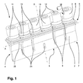
細長いソノトロードヘッド(4)を有する1つのソノトロード(2)を備え、前記ソノトロードヘッド(4)上には、前記ソノトロードヘッド(4)の長手方向に向けられた細長い溶接面(5)が存在し、前記装置(1)はさらに、
作用方向(B)に前記ソノトロード(2)の超音波振動を励起するための少なくとも2つのコンバータ(11)を備え、
反動質量として1つの反力体(3)を備え、
前記少なくとも2つのコンバータ(11)は、前記ソノトロード(2)と前記反力体(3)との間に配置されることを特徴とする、装置(1)。 - 前記ソノトロード(2)は、主に連続的な平面の裏側(8)を有し、前記裏側(8)は、前記作用方向(B)において前記溶接面(5)と反対であり、前記裏側(8)に前記少なくとも2つのコンバータ(11)が載置されることを特徴とする、請求項1に記載の装置(1)。
- 前記ソノトロード(2)側において、前記反力体(3)は、載置接触面を有し、前記載置接触面に前記少なくとも2つのコンバータ(11)が載置されることを特徴とする、請求項1または2に記載の装置(1)。
- 前記反力体(3)の前記載置接触面および前記ソノトロード(2)の前記裏側(8)は、実質的に平行に向けられることを特徴とする、請求項3に記載の装置(1)。
- 前記少なくとも2つのコンバータ(11)は、前記反力体(3)と前記ソノトロード(2)との間に締付けられることを特徴とする、請求項1〜4のいずれか1項に記載の装置(1)。
- 前記少なくとも2つのコンバータ(11)の各々に割当てられたねじ(14)が存在しており、前記ねじにより、前記反力体(3)は、前記ソノトロード(2)にねじ接続されることを特徴とする、請求項1〜5のいずれか1項に記載の装置(1)。
- 前記反力体(3)は、細長くなるように実現され、その長手方向が前記ソノトロードヘッド(4)の前記長手方向(A)と平行になるように向けられることを特徴とする、請求項1〜6のいずれか1項に記載の装置(1)。
- 前記少なくとも2つのコンバータ(11)は、前記ソノトロードヘッド(4)の前記長手方向(A)において直列に配列されることを特徴とする、請求項1〜7のいずれか1項に記載の装置(1)。
- 前記反力体(3)は、前記少なくとも2つのコンバータ(11)間の領域に絞り部(18)を有することを特徴とする、請求項1〜8のいずれか1項に記載の装置(1)。
- 前記装置(1)は、2つを超えるコンバータ(11)を有し、前記反力体(3)は、前記長手方向(A)において隣接する2つのコンバータ(11)間の領域にスロット(22)を有することを特徴とする、請求項1〜9のいずれか1項に記載の装置(1)。
- 前記長手方向に隣接する2つのコンバータ(11)間の各領域に実現された前記スロット(22)が存在することを特徴とする、請求項10に記載の装置(1)。
- 前記ソノトロード(2)は、前記ソノトロードヘッド(4)の前記長手方向(A)に垂直な面に対して実質的にミラー対称となるように実現されることを特徴とする、請求項1〜11のいずれか1項に記載の装置(1)。
- 前記少なくとも2つのコンバータ(11)の各々は、少なくとも1つの圧電セラミックプレートを含むことを特徴とする、請求項1〜12のいずれか1項に記載の装置(1)。
- 前記コンバータ(11)の数が偶数であることを特徴とする、請求項1〜13のいずれか1項に記載の装置(1)。
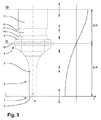
- 前記装置(1)が所望のように動作されると、前記ソノトロード(2)は、前記作用方向(B)に約4分の1波長を形成することを特徴とする、請求項1〜14のいずれか1項に記載の装置(1)。
- 前記装置が所望のように動作されると、前記装置(1)は、前記作用方向(B)に約半波長を形成することを特徴とする、請求項1〜15のいずれか1項に記載の装置(1)。
- 前記ソノトロード(2)の外側に実現される全周保持棚状部(23)が存在し、前記全周保持棚状部(23)は、前記裏側(8)において前記作用方向(B)に垂直な面内に配置され、前記装置(1)が所望のように動作されると、前記全周保持棚状部(23)は節面内に配置されることを特徴とする、請求項1〜16のいずれか1項に記載の装置(1)。
- 前記作用方向(B)は、前記ソノトロードヘッド(4)の前記長手方向(A)に対して実質的に垂直に向けられている、請求項1〜17のいずれか1項に記載の装置(1)。
- 請求項1〜18のいずれか1項に記載の超音波溶接のための装置(1)を備える梱包設備。
Applications Claiming Priority (3)
| Application Number | Priority Date | Filing Date | Title |
|---|---|---|---|
| EP20130162831 EP2789450A1 (de) | 2013-04-09 | 2013-04-09 | Vorrichtung zum Verschweissen mittels Ultraschall |
| EP13162831.5 | 2013-04-09 | ||
| PCT/EP2014/055288 WO2014166702A1 (de) | 2013-04-09 | 2014-03-17 | Vorrichtung zum verschweissen mittels ultraschall |
Publications (3)
| Publication Number | Publication Date |
|---|---|
| JP2016522123A JP2016522123A (ja) | 2016-07-28 |
| JP2016522123A5 JP2016522123A5 (ja) | 2017-04-20 |
| JP6364475B2 true JP6364475B2 (ja) | 2018-07-25 |
Family
ID=48082979
Family Applications (1)
| Application Number | Title | Priority Date | Filing Date |
|---|---|---|---|
| JP2016506826A Expired - Fee Related JP6364475B2 (ja) | 2013-04-09 | 2014-03-17 | 超音波溶接のための装置 |
Country Status (5)
| Country | Link |
|---|---|
| US (1) | US9950823B2 (ja) |
| EP (2) | EP2789450A1 (ja) |
| JP (1) | JP6364475B2 (ja) |
| CN (1) | CN105163926B (ja) |
| WO (1) | WO2014166702A1 (ja) |
Families Citing this family (6)
| Publication number | Priority date | Publication date | Assignee | Title |
|---|---|---|---|---|
| EP3205478A1 (en) * | 2016-02-10 | 2017-08-16 | Ilapak Italia S.p.A. | Ultrasound welding device, in particular for welding flexible packages, optionally made of a plastic material and machine for packaging food products provided with such an ultrasound welding device |
| DE102016116429A1 (de) | 2016-09-02 | 2018-03-08 | Herrmann Ultraschalltechnik Gmbh & Co. Kg | Ultraschallschwingsystem mit Mantelflächenhalterung |
| JP6897035B2 (ja) * | 2016-09-13 | 2021-06-30 | 凸版印刷株式会社 | アンビル及び超音波シール装置 |
| US10052714B2 (en) | 2016-10-14 | 2018-08-21 | Sonics & Materials, Inc. | Ultrasonic welding device with dual converters |
| US10913211B2 (en) | 2017-05-30 | 2021-02-09 | Campbell Soup Company | High rate ultrasonic sealer |
| DE102018108979A1 (de) * | 2018-04-16 | 2019-10-17 | Branson Ultraschall Niederlassung Der Emerson Technologies Gmbh & Co. Ohg | Vibrationsschweißvorrichtung, Verfahren zum Verbinden von mindestens zwei länglichen Bauteilen mittels Vibrationsschweißen sowie ein Herstellungsverfahren für die Vibrationsschweißvorrichtung |
Family Cites Families (17)
| Publication number | Priority date | Publication date | Assignee | Title |
|---|---|---|---|---|
| DE1427629A1 (de) | 1961-02-01 | 1969-06-19 | Ransburg Electro Coating Corp | Zerstaeuber zur Verwendung in einer elektrostatischen Zerstaeubungsanlage zum UEberziehen von Gegenstaenden |
| DE1427329A1 (de) * | 1962-09-29 | 1969-01-16 | Lehfeldt & Co Gmbh Dr | Verfahren,eine Ultraschall-Schweissverbindung zu erzielen |
| US4764907A (en) | 1986-04-30 | 1988-08-16 | Allied Corporation | Underwater transducer |
| SE505864C2 (sv) * | 1993-03-19 | 1997-10-20 | Tetra Laval Holdings & Finance | Anordning för ultraljudsförsegling |
| DE29503122U1 (de) * | 1995-02-24 | 1995-04-27 | Sonotronic Nagel Gmbh | Sonotrode |
| SE9502226L (sv) * | 1995-06-19 | 1996-12-20 | Tetra Laval Holdings & Finance | Anordning vid en drivenhet för en ultraljudsförseglingsenhet |
| DE69926758T2 (de) * | 1998-03-23 | 2006-03-30 | Shikoku Kakoki Co., Ltd. | Ultraschall-siegler |
| JP4316053B2 (ja) * | 1999-07-05 | 2009-08-19 | 四国化工機株式会社 | 超音波シール装置 |
| JP4282179B2 (ja) * | 1999-09-30 | 2009-06-17 | 四国化工機株式会社 | 超音波シール装置 |
| JP4603122B2 (ja) * | 2000-02-23 | 2010-12-22 | 四国化工機株式会社 | 超音波シール装置 |
| DE102005038344A1 (de) * | 2005-08-13 | 2007-02-15 | Tetra Laval Holdings & Finance S.A. | Vorrichtung zum Ultraschallbearbeiten von Werkstücken |
| US7718022B2 (en) * | 2008-05-15 | 2010-05-18 | 3M Innovative Properties Company | Resonant nodal mount for linear ultrasonic horns |
| CN101396866B (zh) * | 2008-11-12 | 2012-02-22 | 大连理工大学 | 应用于聚合物微器件联接的吸附式超声波工具头 |
| EP2368694A1 (en) | 2010-03-22 | 2011-09-28 | Tetra Laval Holdings & Finance S.A. | Sonotrode |
| US8591679B1 (en) * | 2011-12-13 | 2013-11-26 | Rinco Ultrasonics USA, Inc. | Retrofit of a form-fill-seal machine heat station with an advanced ultrasonic welding kit |
| US8689850B2 (en) * | 2010-10-26 | 2014-04-08 | Rinco Ultrasonics, Inc. | Pedestal mounted ultrasonic welding device |
| US9545751B2 (en) * | 2010-10-26 | 2017-01-17 | Rinco Ultrasonics USA, Inc. | Pedestal-mounted ultrasonic welding device |
-
2013
- 2013-04-09 EP EP20130162831 patent/EP2789450A1/de not_active Withdrawn
-
2014
- 2014-03-17 US US14/782,378 patent/US9950823B2/en not_active Expired - Fee Related
- 2014-03-17 EP EP14710317.0A patent/EP2983891B1/de active Active
- 2014-03-17 CN CN201480020349.XA patent/CN105163926B/zh not_active Expired - Fee Related
- 2014-03-17 JP JP2016506826A patent/JP6364475B2/ja not_active Expired - Fee Related
- 2014-03-17 WO PCT/EP2014/055288 patent/WO2014166702A1/de active Application Filing
Also Published As
| Publication number | Publication date |
|---|---|
| CN105163926A (zh) | 2015-12-16 |
| US20160052658A1 (en) | 2016-02-25 |
| CN105163926B (zh) | 2017-09-12 |
| JP2016522123A (ja) | 2016-07-28 |
| EP2789450A1 (de) | 2014-10-15 |
| EP2983891B1 (de) | 2017-05-24 |
| EP2983891A1 (de) | 2016-02-17 |
| US9950823B2 (en) | 2018-04-24 |
| WO2014166702A1 (de) | 2014-10-16 |
Similar Documents
| Publication | Publication Date | Title |
|---|---|---|
| JP6364475B2 (ja) | 超音波溶接のための装置 | |
| US9662680B2 (en) | Ultrasonic transducer | |
| US3370186A (en) | Ultrasonic transducers | |
| JP3647058B2 (ja) | 超音波シール装置 | |
| JP5583179B2 (ja) | ボンディング装置 | |
| CN102802920A (zh) | 超声波发生器 | |
| CN107921482A (zh) | 超声振动传输机构的保持结构 | |
| WO2007020177A3 (de) | Piezoelektrischer aktor für einen ultraschallmotor | |
| CN105408089A (zh) | 具有多个超声焊极的超声波焊接装置 | |
| JP2016137720A (ja) | スクリーン印刷 | |
| JPH10501670A (ja) | 圧電超音波トランスデューサ | |
| JP2004312119A (ja) | 超音波トランスデューサ | |
| KR20170057658A (ko) | 고효율 초음파 진동자 | |
| KR101597560B1 (ko) | 초음파 발생 장치 | |
| JP6774812B2 (ja) | 超音波接合装置 | |
| JP6909333B2 (ja) | 超音波接合装置 | |
| JPH02199994A (ja) | 周波数可変振動子 | |
| JP2014172083A (ja) | ブースタホーン及びブースタホーンを用いた超音波溶着装置 | |
| JP2014168736A (ja) | ボルト締めランジュバン型振動子及びボルト締めランジュバン型振動子を用いた超音波溶着装置 | |
| KR102159856B1 (ko) | 큰 복사 면적을 가지는 초음파 장치 | |
| CN212397193U (zh) | 一种超声波换能器 | |
| JP6554698B2 (ja) | 超音波複合振動装置 | |
| WO2013122048A1 (ja) | 超音波発生装置 | |
| RU6352U1 (ru) | Электромеханический преобразователь | |
| JP2015047599A (ja) | 集束超音波発生装置 |
Legal Events
| Date | Code | Title | Description |
|---|---|---|---|
| A521 | Request for written amendment filed |
Free format text: JAPANESE INTERMEDIATE CODE: A523 Effective date: 20170314 |
|
| A621 | Written request for application examination |
Free format text: JAPANESE INTERMEDIATE CODE: A621 Effective date: 20170314 |
|
| A977 | Report on retrieval |
Free format text: JAPANESE INTERMEDIATE CODE: A971007 Effective date: 20171124 |
|
| A131 | Notification of reasons for refusal |
Free format text: JAPANESE INTERMEDIATE CODE: A131 Effective date: 20171205 |
|
| A521 | Request for written amendment filed |
Free format text: JAPANESE INTERMEDIATE CODE: A523 Effective date: 20180301 |
|
| TRDD | Decision of grant or rejection written | ||
| A01 | Written decision to grant a patent or to grant a registration (utility model) |
Free format text: JAPANESE INTERMEDIATE CODE: A01 Effective date: 20180605 |
|
| A61 | First payment of annual fees (during grant procedure) |
Free format text: JAPANESE INTERMEDIATE CODE: A61 Effective date: 20180702 |
|
| R150 | Certificate of patent or registration of utility model |
Ref document number: 6364475 Country of ref document: JP Free format text: JAPANESE INTERMEDIATE CODE: R150 |
|
| LAPS | Cancellation because of no payment of annual fees |