JP6364475B2 - Equipment for ultrasonic welding - Google Patents
Equipment for ultrasonic welding Download PDFInfo
- Publication number
- JP6364475B2 JP6364475B2 JP2016506826A JP2016506826A JP6364475B2 JP 6364475 B2 JP6364475 B2 JP 6364475B2 JP 2016506826 A JP2016506826 A JP 2016506826A JP 2016506826 A JP2016506826 A JP 2016506826A JP 6364475 B2 JP6364475 B2 JP 6364475B2
- Authority
- JP
- Japan
- Prior art keywords
- sonotrode
- converters
- reaction force
- longitudinal direction
- action
- Prior art date
- Legal status (The legal status is an assumption and is not a legal conclusion. Google has not performed a legal analysis and makes no representation as to the accuracy of the status listed.)
- Expired - Fee Related
Links
Images

Classifications
-
- B—PERFORMING OPERATIONS; TRANSPORTING
- B65—CONVEYING; PACKING; STORING; HANDLING THIN OR FILAMENTARY MATERIAL
- B65B—MACHINES, APPARATUS OR DEVICES FOR, OR METHODS OF, PACKAGING ARTICLES OR MATERIALS; UNPACKING
- B65B51/00—Devices for, or methods of, sealing or securing package folds or closures; Devices for gathering or twisting wrappers, or necks of bags
- B65B51/10—Applying or generating heat or pressure or combinations thereof
- B65B51/22—Applying or generating heat or pressure or combinations thereof by friction or ultrasonic or high-frequency electrical means, i.e. by friction or ultrasonic or induction welding
- B65B51/225—Applying or generating heat or pressure or combinations thereof by friction or ultrasonic or high-frequency electrical means, i.e. by friction or ultrasonic or induction welding by ultrasonic welding
-
- B—PERFORMING OPERATIONS; TRANSPORTING
- B06—GENERATING OR TRANSMITTING MECHANICAL VIBRATIONS IN GENERAL
- B06B—METHODS OR APPARATUS FOR GENERATING OR TRANSMITTING MECHANICAL VIBRATIONS OF INFRASONIC, SONIC, OR ULTRASONIC FREQUENCY, e.g. FOR PERFORMING MECHANICAL WORK IN GENERAL
- B06B3/00—Methods or apparatus specially adapted for transmitting mechanical vibrations of infrasonic, sonic, or ultrasonic frequency
-
- B—PERFORMING OPERATIONS; TRANSPORTING
- B29—WORKING OF PLASTICS; WORKING OF SUBSTANCES IN A PLASTIC STATE IN GENERAL
- B29C—SHAPING OR JOINING OF PLASTICS; SHAPING OF MATERIAL IN A PLASTIC STATE, NOT OTHERWISE PROVIDED FOR; AFTER-TREATMENT OF THE SHAPED PRODUCTS, e.g. REPAIRING
- B29C65/00—Joining or sealing of preformed parts, e.g. welding of plastics materials; Apparatus therefor
- B29C65/02—Joining or sealing of preformed parts, e.g. welding of plastics materials; Apparatus therefor by heating, with or without pressure
- B29C65/08—Joining or sealing of preformed parts, e.g. welding of plastics materials; Apparatus therefor by heating, with or without pressure using ultrasonic vibrations
-
- B—PERFORMING OPERATIONS; TRANSPORTING
- B29—WORKING OF PLASTICS; WORKING OF SUBSTANCES IN A PLASTIC STATE IN GENERAL
- B29C—SHAPING OR JOINING OF PLASTICS; SHAPING OF MATERIAL IN A PLASTIC STATE, NOT OTHERWISE PROVIDED FOR; AFTER-TREATMENT OF THE SHAPED PRODUCTS, e.g. REPAIRING
- B29C66/00—General aspects of processes or apparatus for joining preformed parts
- B29C66/80—General aspects of machine operations or constructions and parts thereof
- B29C66/81—General aspects of the pressing elements, i.e. the elements applying pressure on the parts to be joined in the area to be joined, e.g. the welding jaws or clamps
- B29C66/814—General aspects of the pressing elements, i.e. the elements applying pressure on the parts to be joined in the area to be joined, e.g. the welding jaws or clamps characterised by the design of the pressing elements, e.g. of the welding jaws or clamps
- B29C66/8141—General aspects of the pressing elements, i.e. the elements applying pressure on the parts to be joined in the area to be joined, e.g. the welding jaws or clamps characterised by the design of the pressing elements, e.g. of the welding jaws or clamps characterised by the surface geometry of the part of the pressing elements, e.g. welding jaws or clamps, coming into contact with the parts to be joined
- B29C66/81431—General aspects of the pressing elements, i.e. the elements applying pressure on the parts to be joined in the area to be joined, e.g. the welding jaws or clamps characterised by the design of the pressing elements, e.g. of the welding jaws or clamps characterised by the surface geometry of the part of the pressing elements, e.g. welding jaws or clamps, coming into contact with the parts to be joined comprising a single cavity, e.g. a groove
-
- B—PERFORMING OPERATIONS; TRANSPORTING
- B29—WORKING OF PLASTICS; WORKING OF SUBSTANCES IN A PLASTIC STATE IN GENERAL
- B29C—SHAPING OR JOINING OF PLASTICS; SHAPING OF MATERIAL IN A PLASTIC STATE, NOT OTHERWISE PROVIDED FOR; AFTER-TREATMENT OF THE SHAPED PRODUCTS, e.g. REPAIRING
- B29C66/00—General aspects of processes or apparatus for joining preformed parts
- B29C66/80—General aspects of machine operations or constructions and parts thereof
- B29C66/81—General aspects of the pressing elements, i.e. the elements applying pressure on the parts to be joined in the area to be joined, e.g. the welding jaws or clamps
- B29C66/814—General aspects of the pressing elements, i.e. the elements applying pressure on the parts to be joined in the area to be joined, e.g. the welding jaws or clamps characterised by the design of the pressing elements, e.g. of the welding jaws or clamps
- B29C66/8145—General aspects of the pressing elements, i.e. the elements applying pressure on the parts to be joined in the area to be joined, e.g. the welding jaws or clamps characterised by the design of the pressing elements, e.g. of the welding jaws or clamps characterised by the constructional aspects of the pressing elements, e.g. of the welding jaws or clamps
-
- B—PERFORMING OPERATIONS; TRANSPORTING
- B29—WORKING OF PLASTICS; WORKING OF SUBSTANCES IN A PLASTIC STATE IN GENERAL
- B29C—SHAPING OR JOINING OF PLASTICS; SHAPING OF MATERIAL IN A PLASTIC STATE, NOT OTHERWISE PROVIDED FOR; AFTER-TREATMENT OF THE SHAPED PRODUCTS, e.g. REPAIRING
- B29C66/00—General aspects of processes or apparatus for joining preformed parts
- B29C66/80—General aspects of machine operations or constructions and parts thereof
- B29C66/84—Specific machine types or machines suitable for specific applications
- B29C66/849—Packaging machines
-
- B—PERFORMING OPERATIONS; TRANSPORTING
- B29—WORKING OF PLASTICS; WORKING OF SUBSTANCES IN A PLASTIC STATE IN GENERAL
- B29C—SHAPING OR JOINING OF PLASTICS; SHAPING OF MATERIAL IN A PLASTIC STATE, NOT OTHERWISE PROVIDED FOR; AFTER-TREATMENT OF THE SHAPED PRODUCTS, e.g. REPAIRING
- B29C66/00—General aspects of processes or apparatus for joining preformed parts
- B29C66/01—General aspects dealing with the joint area or with the area to be joined
- B29C66/05—Particular design of joint configurations
- B29C66/10—Particular design of joint configurations particular design of the joint cross-sections
- B29C66/11—Joint cross-sections comprising a single joint-segment, i.e. one of the parts to be joined comprising a single joint-segment in the joint cross-section
- B29C66/112—Single lapped joints
- B29C66/1122—Single lap to lap joints, i.e. overlap joints
-
- B—PERFORMING OPERATIONS; TRANSPORTING
- B29—WORKING OF PLASTICS; WORKING OF SUBSTANCES IN A PLASTIC STATE IN GENERAL
- B29C—SHAPING OR JOINING OF PLASTICS; SHAPING OF MATERIAL IN A PLASTIC STATE, NOT OTHERWISE PROVIDED FOR; AFTER-TREATMENT OF THE SHAPED PRODUCTS, e.g. REPAIRING
- B29C66/00—General aspects of processes or apparatus for joining preformed parts
- B29C66/40—General aspects of joining substantially flat articles, e.g. plates, sheets or web-like materials; Making flat seams in tubular or hollow articles; Joining single elements to substantially flat surfaces
- B29C66/41—Joining substantially flat articles ; Making flat seams in tubular or hollow articles
- B29C66/43—Joining a relatively small portion of the surface of said articles
- B29C66/431—Joining the articles to themselves
- B29C66/4312—Joining the articles to themselves for making flat seams in tubular or hollow articles, e.g. transversal seams
-
- B—PERFORMING OPERATIONS; TRANSPORTING
- B29—WORKING OF PLASTICS; WORKING OF SUBSTANCES IN A PLASTIC STATE IN GENERAL
- B29C—SHAPING OR JOINING OF PLASTICS; SHAPING OF MATERIAL IN A PLASTIC STATE, NOT OTHERWISE PROVIDED FOR; AFTER-TREATMENT OF THE SHAPED PRODUCTS, e.g. REPAIRING
- B29C66/00—General aspects of processes or apparatus for joining preformed parts
- B29C66/70—General aspects of processes or apparatus for joining preformed parts characterised by the composition, physical properties or the structure of the material of the parts to be joined; Joining with non-plastics material
- B29C66/72—General aspects of processes or apparatus for joining preformed parts characterised by the composition, physical properties or the structure of the material of the parts to be joined; Joining with non-plastics material characterised by the structure of the material of the parts to be joined
- B29C66/723—General aspects of processes or apparatus for joining preformed parts characterised by the composition, physical properties or the structure of the material of the parts to be joined; Joining with non-plastics material characterised by the structure of the material of the parts to be joined being multi-layered
- B29C66/7232—General aspects of processes or apparatus for joining preformed parts characterised by the composition, physical properties or the structure of the material of the parts to be joined; Joining with non-plastics material characterised by the structure of the material of the parts to be joined being multi-layered comprising a non-plastics layer
- B29C66/72327—General aspects of processes or apparatus for joining preformed parts characterised by the composition, physical properties or the structure of the material of the parts to be joined; Joining with non-plastics material characterised by the structure of the material of the parts to be joined being multi-layered comprising a non-plastics layer consisting of natural products or their composites, not provided for in B29C66/72321 - B29C66/72324
- B29C66/72328—Paper
-
- B—PERFORMING OPERATIONS; TRANSPORTING
- B29—WORKING OF PLASTICS; WORKING OF SUBSTANCES IN A PLASTIC STATE IN GENERAL
- B29C—SHAPING OR JOINING OF PLASTICS; SHAPING OF MATERIAL IN A PLASTIC STATE, NOT OTHERWISE PROVIDED FOR; AFTER-TREATMENT OF THE SHAPED PRODUCTS, e.g. REPAIRING
- B29C66/00—General aspects of processes or apparatus for joining preformed parts
- B29C66/70—General aspects of processes or apparatus for joining preformed parts characterised by the composition, physical properties or the structure of the material of the parts to be joined; Joining with non-plastics material
- B29C66/73—General aspects of processes or apparatus for joining preformed parts characterised by the composition, physical properties or the structure of the material of the parts to be joined; Joining with non-plastics material characterised by the intensive physical properties of the material of the parts to be joined, by the optical properties of the material of the parts to be joined, by the extensive physical properties of the parts to be joined, by the state of the material of the parts to be joined or by the material of the parts to be joined being a thermoplastic or a thermoset
- B29C66/739—General aspects of processes or apparatus for joining preformed parts characterised by the composition, physical properties or the structure of the material of the parts to be joined; Joining with non-plastics material characterised by the intensive physical properties of the material of the parts to be joined, by the optical properties of the material of the parts to be joined, by the extensive physical properties of the parts to be joined, by the state of the material of the parts to be joined or by the material of the parts to be joined being a thermoplastic or a thermoset characterised by the material of the parts to be joined being a thermoplastic or a thermoset
- B29C66/7392—General aspects of processes or apparatus for joining preformed parts characterised by the composition, physical properties or the structure of the material of the parts to be joined; Joining with non-plastics material characterised by the intensive physical properties of the material of the parts to be joined, by the optical properties of the material of the parts to be joined, by the extensive physical properties of the parts to be joined, by the state of the material of the parts to be joined or by the material of the parts to be joined being a thermoplastic or a thermoset characterised by the material of the parts to be joined being a thermoplastic or a thermoset characterised by the material of at least one of the parts being a thermoplastic
- B29C66/73921—General aspects of processes or apparatus for joining preformed parts characterised by the composition, physical properties or the structure of the material of the parts to be joined; Joining with non-plastics material characterised by the intensive physical properties of the material of the parts to be joined, by the optical properties of the material of the parts to be joined, by the extensive physical properties of the parts to be joined, by the state of the material of the parts to be joined or by the material of the parts to be joined being a thermoplastic or a thermoset characterised by the material of the parts to be joined being a thermoplastic or a thermoset characterised by the material of at least one of the parts being a thermoplastic characterised by the materials of both parts being thermoplastics
-
- B—PERFORMING OPERATIONS; TRANSPORTING
- B29—WORKING OF PLASTICS; WORKING OF SUBSTANCES IN A PLASTIC STATE IN GENERAL
- B29L—INDEXING SCHEME ASSOCIATED WITH SUBCLASS B29C, RELATING TO PARTICULAR ARTICLES
- B29L2031/00—Other particular articles
- B29L2031/712—Containers; Packaging elements or accessories, Packages
Description
本発明は、独立クレームのプレアンブルに係る、超音波溶接のための装置に関する。 The present invention relates to an apparatus for ultrasonic welding according to the preamble of the independent claim.
超音波溶接のための装置は、通常、コンバータとソノトロードとを有する。コンバータは、たとえば圧電材料により、発振器によって発生される電気振動を機械運動に変換する。このように発生された機械振動はソノトロード内に導入され、ソノトロードは、固有モードにおいてできる限り振動するように励起される。溶接材料に振動を付与する目的で、ソノトロードは、典型的には、ソノトロードヘッド上に溶接面を有する。さらに、溶接面において振動振幅を増幅するブースターが設けられることもある。この場合、ブースターは、たとえば、ソノトロードの特別な幾何学設計、またはソノトロードヘッドによって達成され得る。 An apparatus for ultrasonic welding typically has a converter and a sonotrode. The converter converts the electrical vibration generated by the oscillator into mechanical motion, for example with a piezoelectric material. The mechanical vibration generated in this way is introduced into the sonotrode, which is excited to vibrate as much as possible in the eigenmode. For the purpose of imparting vibrations to the welding material, sonotrodes typically have a welding surface on the sonotrode head. Furthermore, a booster that amplifies the vibration amplitude on the weld surface may be provided. In this case, the booster can be achieved, for example, by a special geometric design of the sonotrode, or a sonotrode head.
このような装置は、とりわけ、梱包設備において使用され、梱包設備では、たとえば、紙と熱可塑性材料とからなる積層体を有する梱包材料が、たとえば容器を形成するように成形され、容器は充填された後に閉じられる。典型的には、容器の形は長方形、直方体または四面体であり、たとえばジュースまたは牛乳などの液体が充填される。容器は、一般的に、梱包材料の連続的なウェブから成形され、充填された後に密封され、分離される。典型的には、容器を成形し、密封する際に熱溶接法が使用される。梱包材料によっては、熱エネルギーはさまざまな方法で印加され得る(梱包材料がたとえばアルミニウム箔などの導電層を含む場合、誘導などによって)が、溶接領域において積層体を加熱する目的で超音波振動を導入することが、特に汎用的に適用可能であることが見出された。 Such an apparatus is used, inter alia, in a packaging facility where, for example, a packaging material having a laminate of paper and thermoplastic material is shaped, for example, to form a container, and the container is filled. It is closed after. Typically, the container has a rectangular, rectangular or tetrahedral shape and is filled with a liquid such as juice or milk. Containers are typically molded from a continuous web of packing material, sealed and separated after being filled. Typically, heat welding is used in forming and sealing the container. Depending on the packaging material, thermal energy can be applied in a variety of ways (such as by induction if the packaging material includes a conductive layer such as an aluminum foil), but ultrasonic vibration is used to heat the laminate in the weld area. It has been found that the introduction is particularly applicable for general purposes.
しかし、容器の形状によっては、比較的長い溶接継ぎ目が必要となる。均一な溶接および/または密封を達成するためには、超音波振動は、全溶接領域にわたってできるだけ均一に導入される必要がある。 However, depending on the shape of the container, a relatively long weld seam is required. In order to achieve uniform welding and / or sealing, ultrasonic vibrations need to be introduced as uniformly as possible across the entire weld area.
この目的のために、たとえばEP 615 907 A1に記載されるものなどの既知の装置は、互いに隣り合って配置され、細長い溶接面を有する複数のソノトロードを有している。各ソノトロードは、ソノトロードの裏側に配列されたそれぞれの1つのコンバータによって励起される。各コンバータは、反動質量として釣合錘を搭載している。半波長を有するソノトロード全体を形成するために、コンバータには、ソノトロードの裏側に配列された複数の反力体がさらに存在している。個々のソノトロードは互いに隣り合って配置されているため、溶接面は、あるソノトロードから隣接するソノトロードへの移行部において途切れている。この配置によって生じる溶接継ぎ目は、特に、箔などの薄い材料の溶接の場合には、これらの地点において同様に途切れるおそれがある。溶接継ぎ目におけるこれらのギャップは、たとえば、特に液体の梱包の場合に、望ましくない漏れを招いてしまう。 For this purpose, known devices, for example those described in EP 615 907 A1, have a plurality of sonotrodes arranged next to each other and having an elongated weld surface. Each sonotrode is excited by a respective converter arranged on the back of the sonotrode. Each converter is equipped with a counterweight as a reaction mass. In order to form the entire sonotrode having a half wavelength, the converter further includes a plurality of reaction force elements arranged on the back side of the sonotrode. Since the individual sonotrodes are arranged next to each other, the weld surface is interrupted at the transition from one sonotrode to the adjacent sonotrode. The weld seam produced by this arrangement can be similarly broken at these points, particularly when welding thin materials such as foil. These gaps in the weld seam can lead to undesirable leakage, for example, particularly in the case of liquid packaging.
このため、WO2011/117119A1は、その長さにわたって分散して配置された3つのコンバータによって一体型部品として実現された細長いソノトロードを励起することを提案している。この場合、ソノトロードの均一な励起が不可欠である。なぜなら、不均一な機械的荷重は、材料の早期の疲労および損傷を招き得るためである。WO2011/117119A1のコンバータは、それぞれ対応付けられた凹部内に配置されており、該凹部は、ソノトロードの裏側に実現され、主に、その中に配列されるコンバータを完全に収容する。ソノトロードは、長手方向に対して垂直に延びるスロットを有しており、該スロットは、より均一な溶接効果を得るために望ましくない振動モードを低減する。このソノトロードは確かに良好な溶接効果を付与するものの、その製造は細かく、コストがかかる。さらに、ソノトロードの設計は比較的複雑で、大きなスペースを占めてしまう。 For this reason, WO 2011/117119 A1 proposes to excite an elongate sonotrode realized as an integral part by three converters distributed over its length. In this case, uniform excitation of the sonotrode is essential. This is because uneven mechanical loading can lead to premature fatigue and damage of the material. The converters of WO2011 / 117119A1 are each arranged in a corresponding recess, which is realized on the back side of the sonotrode and mainly contains the converter arranged in it completely. The sonotrode has a slot extending perpendicular to the longitudinal direction, which reduces undesirable vibration modes in order to obtain a more uniform welding effect. While this sonotrode certainly gives a good welding effect, its production is fine and costly. In addition, the sonotrode design is relatively complex and takes up a lot of space.
したがって、本発明の目的は、先行技術の欠点を克服することである。特に、本発明の目的は、安価で製造が容易であり、特に、ソノトロードが細長い設計からなる場合であっても均一な溶接を確保する、小型な設計の超音波溶接装置を形成することである。さらに、溶接材料内へのエネルギーの効率的な入力が確保される。 The object of the present invention is therefore to overcome the drawbacks of the prior art. In particular, an object of the present invention is to form an ultrasonic welding apparatus with a small design that is inexpensive and easy to manufacture, and in particular, ensures uniform welding even when the sonotrode has an elongated design. . Furthermore, an efficient input of energy into the welding material is ensured.
これらの目的は、独立クレームの特徴によって達成される。独立クレームは、超音波溶接のための装置に関し、該装置は、細長いソノトロードヘッドを有するソノトロードを含み、ソノトロードヘッド上には、ソノトロードヘッドの長手方向に向けられた細長い溶接面が存在し、装置はさらに、作用方向にソノトロードの超音波振動を励起するための少なくとも2つのコンバータを含み、作用方向は、好ましくは、ソノトロードヘッドの長手方向に対して実質的に垂直に向けられており、装置はさらに、反動質量として反力体を含む。装置は、少なくとも2つのコンバータが、ソノトロードと反力体との間に配置されることを特徴とする。特に、この場合、ソノトロードおよび反力体は、作用方向に配置され、これらの間にはコンバータが配置されている。 These objects are achieved by the features of the independent claims. The independent claim relates to an apparatus for ultrasonic welding, the apparatus comprising a sonotrode having an elongate sonotrode head, on which an elongate weld surface oriented in the longitudinal direction of the sonotrode head And the apparatus further includes at least two converters for exciting ultrasonic vibrations of the sonotrode in the direction of action, the direction of action preferably being substantially perpendicular to the longitudinal direction of the sonotrode head Directed and the device further includes a reaction body as a reaction mass. The device is characterized in that at least two converters are arranged between the sonotrode and the reaction body. In particular, in this case, the sonotrode and the reaction force body are arranged in the acting direction, and a converter is arranged between them.
反動質量として実現される反力体は、好ましくは、ソノトロードと別個の部品として実現される。反力体およびソノトロードは、それぞれ好ましくは、一体型の連続的な部品として実現される。少なくとも2つのコンバータおよびソノトロードのための反動質量として作用する単一の反力体しか存在しないため、装置は特に簡略な設計からなることができる。さらに、反力体は、追加のカップリングを形成し、このカップリングにより、装置の振動挙動が、溶接面の均一な振動に有利なように選択的に最適化され得る。特に、ソノトロードの望ましくない振動挙動が、反力体の選択的な設計により比較的容易にさらに補償され得る。 The reaction force body realized as a reaction mass is preferably realized as a separate part from the sonotrode. The reaction force body and the sonotrode are each preferably realized as an integral continuous part. The device can be of a particularly simple design since there is only a single reaction body acting as a reaction mass for at least two converters and sonotrode. Furthermore, the reaction body forms an additional coupling, by which the vibration behavior of the device can be selectively optimized to favor uniform vibration of the weld surface. In particular, the undesirable vibration behavior of the sonotrode can be further compensated relatively easily by the selective design of the reaction force body.
コンバータが反力体とソノトロードとの間に配置されているため、反力体は、コンバータの釣合錘として、かつソノトロードのための反動質量としても同時に作用し得る。部品は、たとえば、作用方向に積層されて配置され得る(コンバータがソノトロードと反力体との間にある)ため、この配置はまた、作用方向によって規定される方向に自然に対応する。 Since the converter is arranged between the reaction force body and the sonotrode, the reaction force body can simultaneously act as a counterweight for the converter and also as a reaction mass for the sonotrode. This arrangement also naturally corresponds to the direction defined by the direction of action, for example because the parts can be arranged stacked in the direction of action (the converter is between the sonotrode and the reaction body).
ソノトロードヘッドは、たとえば、ブレードの形状となり、かつ、長手方向に対して垂直な断面が、凹型曲線に沿って少なくとも部分的に、溶接面から裏側に向かってそれるように既知の方法で設計され得る。この場合、曲線は、たとえば円の一部分、指数関数またはカテノイドによって規定され得る。ソノトロードヘッドは、たとえば、作用方向に対して垂直な、望ましくない振動モードを補償するまたは排除するために、作用方向に向けられたスロットによって、既知の方法で、横方向に開かれていてもよい。 The sonotrode head is, for example, in the form of a blade and in a known manner such that the cross section perpendicular to the longitudinal direction deviates from the welding surface to the back side at least partly along the concave curve. Can be designed. In this case, the curve may be defined by a part of a circle, an exponential function or a catenoid, for example. The sonotrode head is opened laterally in a known manner, for example by a slot oriented in the direction of action, to compensate or eliminate unwanted vibration modes perpendicular to the direction of action. Also good.
ソノトロードヘッドの長さによっては、複数のコンバータが存在してもよいことが理解される。好ましくは、この場合、コンバータは、反力体とソノトロードとの間に配置される。しかし、基本的には、少なくとも2つのコンバータの群にそれぞれ1つの反力体が割当てられる装置も想定され得る。 It will be appreciated that there may be multiple converters depending on the length of the sonotrode head. Preferably, in this case, the converter is arranged between the reaction force body and the sonotrode. Basically, however, it is also possible to envisage a device in which one reaction force is assigned to each group of at least two converters.
好ましくは、ソノトロードは、主に連続的な、特に平面の、裏側を有し、裏側は、作用方向において溶接面と反対であり、裏側に少なくとも2つのコンバータが載置される。本発明に従うと、少なくとも2つのコンバータがソノトロードと反力体との間に配置されるため、反力体として作用するおよび/またはコンバータを受けるように実現される構造体がソノトロードの裏側に存在する必要がない。要件によっては、コンバータを配置するために、たとえば若干の凹みが実現されてもよいことは明らかである。基本的には、これは製造をより細かくしてしまうが、要件によってはそれでも検討可能である。しかし、好ましくは、ソノトロードの裏側は、主に連続的な平面として実現される。主に連続的な裏側は、質量を減らすために、たとえばねじ孔および/または凹部によって、所々開かれていてもよいことが理解される。 Preferably, the sonotrode has a back side which is mainly continuous, in particular planar, which is opposite the welding surface in the direction of action and on which at least two converters are mounted. According to the invention, since at least two converters are arranged between the sonotrode and the reaction force body, there is a structure behind the sonotrode that acts as a reaction force and / or is implemented to receive the converter. There is no need. Obviously, depending on the requirements, for example, a slight dent may be realized in order to place the converter. Basically, this makes the production finer, but it can still be considered depending on the requirements. However, preferably the back side of the sonotrode is realized mainly as a continuous plane. It will be appreciated that the predominantly continuous backside may be opened in some places, for example by screw holes and / or recesses, to reduce mass.
同様に、有利には、ソノトロード側において、反力体は、載置接触面、特に平面の載置接触面を有し、載置接触面に少なくとも2つのコンバータが載置される。この場合、反力体および/またはソノトロードは、それぞれの部品の構造が、それぞれ他の部品に向かって、載置接触面または裏側から突出しないように実現され得る。載置接触面上に存在する若干の凹部または構造が存在していてもよいことが理解される。たとえば、コンバータを配置するために、若干の凹部が実現され得る。基本的には、これは製造をより細かくするが、要件によってはそれでも検討可能である。 Similarly, advantageously, on the sonotrode side, the reaction body has a mounting contact surface, in particular a flat mounting contact surface, on which at least two converters are mounted. In this case, the reaction force body and / or the sonotrode can be realized such that the structure of each part does not protrude from the mounting contact surface or the back side toward the other part. It will be appreciated that there may be some recesses or structures present on the mounting contact surface. For example, some recesses may be realized to place the converter. Basically this makes the production finer, but it can still be considered depending on the requirements.
好ましくは、反力体の載置接触面およびソノトロードの裏側は、互いに対して実質的に平行に向けられる。これにより、たとえば、主に円柱の形態で実現されるコンバータが、一方では裏側において、他方では載置接触面において、容易に実現される平行平面な端面を有して配置され得る。特に、コンバータは特別な方法で実現される必要がない。この場合、コンバータは、たとえば接触板もしくは接触ディスクなどの接触要素を介してまたは直接それぞれの面に載置され得る。この場合、接触要素は、コンバータの一部であってもよく、またはコンバータと対応する面との間に配置される別個の部品であってもよい。 Preferably, the mounting contact surface of the reaction force body and the back side of the sonotrode are oriented substantially parallel to each other. Thereby, for example, a converter realized mainly in the form of a cylinder can be arranged with a parallel flat end face that is easily realized on the one hand on the back side and on the other hand on the mounting contact surface. In particular, the converter need not be implemented in a special way. In this case, the converter can be mounted via a contact element such as a contact plate or a contact disk or directly on the respective surface. In this case, the contact element may be part of the converter, or it may be a separate part arranged between the converter and the corresponding surface.
この場合、少なくとも2つのコンバータは、反力体とソノトロードとの間に締付けられ得る。反力体、少なくとも2つのコンバータおよびソノトロードは、これにより、構造的に簡便な方法で製造され得るスタックを形成する。たとえば、反力体がソノトロードに適切にねじ接続されると、締付作用により、反力体およびソノトロードの両方のコンバータに対する最適な機械的および熱的接触が実現可能となる。一方では、これによりコンバータの機械振動がソノトロード内へと最適に導入可能となる。他方では、コンバータ内で発生する熱がソノトロードおよび/または反力体を介して最適に除去され得る。 In this case, the at least two converters can be clamped between the reaction force body and the sonotrode. The reaction body, the at least two converters and the sonotrode thereby form a stack that can be manufactured in a structurally simple manner. For example, when the reaction force is properly threaded to the sonotrode, the clamping action allows for optimal mechanical and thermal contact to both the reaction force and the sonotrode converter. On the one hand, this allows the mechanical vibrations of the converter to be optimally introduced into the sonotrode. On the other hand, the heat generated in the converter can be optimally removed via sonotrode and / or reaction force.
好ましくは、少なくとも2つのコンバータの各々に割当てられたねじが存在しており、ねじにより、反力体は、特にそれぞれのコンバータの貫通通路によって、ソノトロードにねじ接続される。これにより、コンバータの作用方向に向かって中央に作用する最適な締付効果が簡便に達成され得る。 Preferably, there is a screw assigned to each of the at least two converters, by means of which the reaction force is screwed to the sonotrode, in particular by means of a through passage of the respective converter. As a result, the optimum tightening effect acting in the center in the direction of action of the converter can be easily achieved.
好ましくは、反力体は、細長くなるように、特に棒として実現され、その長手方向がソノトロードヘッドの長手方向と平行になるように向けられる。これにより、反力体は、ソノトロードに最適に適合されて、小型の設計からなる。好ましくは、反力体の長手方向における寸法付けは、ソノトロードヘッドの対応する寸法付けに実質的に対応する。 Preferably, the reaction body is realized as an elongate, in particular as a bar, and is oriented so that its longitudinal direction is parallel to the longitudinal direction of the sonotrode head. Thereby, the reaction body is optimally adapted to the sonotrode and has a compact design. Preferably, the longitudinal dimensioning of the reaction body substantially corresponds to the corresponding dimensioning of the sonotrode head.
有利には、少なくとも2つのコンバータは、ソノトロードヘッドの長手方向において直列に配列される。これにより、コンバータによって導入される振動が細長いソノトロードに最適に分散される。コンバータが2つを超える場合、隣接するコンバータは、好ましくは、それぞれ互いから一定の距離あけられる。コンバータが複数の場合、コンバータが、たとえば、2つの平行な列または、たとえば振動に関して有利なパターンなどのパターンで配列されることも基本的には想定され得る。通常、ソノトロードヘッドの細長い形状のため、コンバータは、長手方向に直列に配置されることが好ましい。 Advantageously, the at least two converters are arranged in series in the longitudinal direction of the sonotrode head. This optimally distributes the vibration introduced by the converter to the elongated sonotrode. If there are more than two converters, adjacent converters are preferably spaced a distance from each other. In the case of a plurality of converters, it can also basically be envisaged that the converters are arranged, for example, in two parallel rows or in a pattern, for example an advantageous pattern for vibration. Usually, because of the elongated shape of the sonotrode head, the converters are preferably arranged in series in the longitudinal direction.
反力体は、特に、作用方向に対して、かつ長手方向に対して主に垂直方向に、少なくとも2つのコンバータ間の領域に絞り部を有し得る。複数のコンバータの場合、反力体は、コンバータの各隣接する対の間に対応する絞り部を有し得る。絞り部により、材料が節減され、振動挙動が最適化されることができる。好ましくは、絞り部は、作用方向に垂直な方向および長手方向において対称である。 The reaction body may have a restriction in the region between at least two converters, in particular in the direction of action and mainly in the direction perpendicular to the longitudinal direction. In the case of a plurality of converters, the reaction body may have a corresponding throttle between each adjacent pair of converters. The constriction can save material and optimize vibration behavior. Preferably, the throttle part is symmetric in the direction perpendicular to the action direction and in the longitudinal direction.
この目的のために、特に2つを超えるコンバータを有する装置である場合、反力体は、長手方向に隣接する2つのコンバータ間の領域にスロットをさらに有していてもよく、このスロットは、特に、ソノトロードに向かって開いており、好ましくは作用方向に向けられている。この場合、スロットは、好ましくは、長手方向に対して横方向に、反力体全体を通って延びる。スロットは、反力体のさらなる絞り部を構成し、これにより、反力体の振動挙動が要件に合わせて調整され得る。 For this purpose, in particular in the case of a device with more than two converters, the reaction body may further have a slot in the region between two longitudinally adjacent converters, In particular, it is open towards the sonotrode and is preferably directed in the direction of action. In this case, the slot preferably extends through the entire reaction body transversely to the longitudinal direction. The slot constitutes a further throttle part of the reaction body, so that the vibration behavior of the reaction body can be adjusted to the requirements.
好ましくは、長手方向に隣接する2つのコンバータ間の各領域に実現されたスロットが存在する。この場合、スロットは、上記のように実現され、特に、ソノトロードに向かって開かれており、好ましくは、作用方向に向けられていてもよい。しかし、コンバータの数が偶数である場合には、中間の対においてスロットが省略されていてもよい。 Preferably, there are slots implemented in each region between two longitudinally adjacent converters. In this case, the slot is realized as described above, in particular it is open towards the sonotrode and may preferably be oriented in the direction of action. However, if the number of converters is an even number, the slots may be omitted in the middle pair.
好ましくは、反力体の長手方向中心からより離れた距離にあるスロットは、より大きな深さを有する。これにより、スロットが反力体の長手方向端に近づくにつれて、スロットの深さが増大する。これにより、反力体の振動挙動が、特に長手方向端に向けて、選択的に影響され得る。 Preferably, the slots that are further away from the longitudinal center of the reaction body have a greater depth. Thereby, the depth of the slot increases as the slot approaches the longitudinal end of the reaction body. Thereby, the vibration behavior of the reaction force body can be influenced selectively, particularly toward the longitudinal end.
全体的に、装置は、ソノトロードヘッドの長手方向に垂直な面に対して実質的にミラー対称となるように実現され得る。この場合、たとえば、コンバータに対する片側のみの接続など、対称から若干のずれが存在していてもよい。このため、対称面は、長手方向に垂直であり、かつソノトロードおよび反力体の長手方向中心を貫通する面であることが分かる。 Overall, the device can be realized to be substantially mirror symmetric with respect to a plane perpendicular to the longitudinal direction of the sonotrode head. In this case, there may be a slight deviation from symmetry, for example, only one side connection to the converter. For this reason, it turns out that a symmetrical surface is a surface perpendicular | vertical to a longitudinal direction and penetrating the longitudinal direction center of a sonotrode and a reaction force body.
好ましくは、少なくとも2つのコンバータの各々は、少なくとも1つの圧電セラミックプレート、好ましくは、複数の圧電セラミックプレートを含むスタックを含む。セラミックプレートは、通常、複数のプレートが積層されると、主に円形の円筒形スタックが得られるように、その形状が円形である。基本的には、他の電歪性および/または磁歪性材料を主体とした任意の他のコンバータも使用され得る。 Preferably, each of the at least two converters comprises a stack comprising at least one piezoelectric ceramic plate, preferably a plurality of piezoelectric ceramic plates. Ceramic plates are typically circular in shape so that when a plurality of plates are stacked, a predominantly circular cylindrical stack is obtained. In principle, any other converter based on other electrostrictive and / or magnetostrictive materials can also be used.
コンバータはそれぞれ、接触要素を含んでいてもよく、接触要素は、たとえば接触プレートとして実現される。接触要素は、特に、ソノトロードをコンバータに接触させるための接触領域において、および/または、接触体に接触するための接触領域において実現される。接触プレートは、たとえば、アルミニウムなどの金属を含み得る。接触要素はさらに、別個の部品として実現され得る、コンバータとソノトロードの間に配置され得る、および/または、適宜、コンバータと反力体との間に配置され得る。接触要素は、コンバータのソノトロードに対する最適な熱的および機械的接触を設ける。 Each converter may include a contact element, which is realized, for example, as a contact plate. The contact element is realized in particular in the contact area for contacting the sonotrode with the converter and / or in the contact area for contacting the contact body. The contact plate can include a metal such as, for example, aluminum. The contact element can further be realized as a separate part, arranged between the converter and the sonotrode, and / or optionally arranged between the converter and the reaction body. The contact element provides optimal thermal and mechanical contact to the sonotrode of the converter.
この場合、コンバータの数が偶数であり、特に、2、4または6であってもよい。要件によっては、奇数のコンバータを有する設計も同様に使用され得ることが明らかである。 In this case, the number of converters is an even number, in particular 2, 4 or 6. Obviously, depending on the requirements, designs with an odd number of converters can be used as well.
好ましくは、装置が所望のように動作されると、ソノトロードは、作用方向に約4分の1波長を形成する。通常、ソノトロードは、その共振周波数が使用される発振器によって与えられる周波数と実質的に一致するように、共振器として実現される。この場合、好ましくは、できる限り深く、そのため、通常エネルギーの面で特に安定しかつ有利な自然振動が励起される。 Preferably, when the device is operated as desired, the sonotrode forms about a quarter wavelength in the direction of action. Usually the sonotrode is implemented as a resonator so that its resonant frequency substantially matches the frequency provided by the oscillator used. In this case, it is preferably as deep as possible, so that natural vibrations which are particularly stable and advantageous in terms of normal energy are excited.
有利には、装置が所望のように動作されると、装置は、作用方向に約半波長を形成する。特に、装置が半波長として実現される場合、ソノトロードヘッドおよび反力体は、共振器の自由端として、節面に対して正反対に偏向する。節面内では、振幅が大幅に消失する。これにより、特に、ソノトロードが約4分の1波長を有して実現される場合、装置の節面は、作用方向に対して所望のように動作されると、その裏側においてソノトロードの端領域に配置される。 Advantageously, when the device is operated as desired, the device forms about half a wavelength in the direction of action. In particular, if the device is realized as a half wavelength, the sonotrode head and the reaction force deflect diametrically against the nodal plane as the free end of the resonator. Within the nodal plane, the amplitude disappears significantly. Thereby, especially when the sonotrode is realized with about a quarter wavelength, the nodal surface of the device is moved to the end region of the sonotrode on its back side when operated as desired with respect to the direction of action. Be placed.
節面の領域内では、ソノトロードと、適宜全装置とが、固定された保持構造に取付けられていてもよい。なぜなら、そこでは発振がほとんど生じないためである。したがって、好ましくは、ソノトロードの外側に実現される全周保持棚状部が存在し、全周保持棚状部は、裏側において作用方向に垂直な面内に配置され、装置が所望のように動作されると、全周保持棚状部は、節面内に配置される。 Within the nodal surface region, the sonotrode and, where appropriate, all devices may be attached to a fixed holding structure. This is because there is almost no oscillation there. Therefore, preferably there is an all-around holding shelf realized on the outside of the sonotrode, and the all-around holding shelf is arranged in a plane perpendicular to the direction of action on the back side and the device operates as desired Then, the all-around holding shelf-like portion is arranged in the node surface.
この目的のために、装置の部品は、このように互いに整合するように実現されることが理解される。 For this purpose, it is understood that the parts of the device are thus realized in alignment with one another.
本発明はさらに、超音波溶接のための本発明に係る装置を含む梱包設備に関する。この場合、装置は、梱包設備においてソノトロードの保持棚状部上に設置される。 The invention further relates to a packaging facility comprising an apparatus according to the invention for ultrasonic welding. In this case, the apparatus is installed on a sonotrode holding shelf in the packaging facility.
以下に、例示的な実施形態の例証に基づいて本発明をより詳細に説明する。 In the following, the invention will be described in more detail on the basis of an illustration of exemplary embodiments.
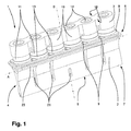
図1は、超音波溶接のための本発明に係る装置1の外側斜視図を示す。装置1は、ソノトロード2と反力体3とを含む。ソノトロード2は、細長い設計からなり、長手方向Aを規定する。ソノトロード2は、Aに垂直な作用方向Bにおいて長手方向の超音波振動を導入するように設計されている。図2は、図1の斜視図の分解図を示す。図1および図2を以下にともに説明する。
FIG. 1 shows an outer perspective view of an
ソノトロード2は、ブレードの形状で実現された細長いソノトロードヘッド4を有する。ソノトロードヘッド4は、Aに沿って向けられ、実質的にソノトロード2の全長にわたって延びる。「ブレードの形状で」とは、Aの方向において主に角柱形であり、Aに垂直な断面が、作用方向Bにおいて少なくとも部分的に、ソノトロード2のベース領域6から作業領域7に向かってテーパ状となる形状を指す。好ましくは、テーパ状の断面は、作用方向Bにおいて作業領域7に向かって収束する凹型曲線によって、少なくとも部分的に画定される。作業領域7においては、本発明のソノトロードヘッド4は、断面が主に平行な側面を有している(これは、たとえば図3を参照)。
The
作業領域7においては、ソノトロードヘッド4は、溶接面5によって作用方向Bにおいて画定されている。溶接面5は、狭い長方形を有しており、その長手方向がAと平行になるように、作用方向Bに対して垂直に向けられている。溶接面5は、作業領域側においてソノトロード2の端を構成している。言い換えると、ソノトロード2は、Bの方向において溶接面5から突出する要素または構造を一切有さない。溶接面5上にAに沿って長手方向溝が実現されており、該溝は、たとえば梱包設備などのナイフ(図示せず)のための係合領域を設けており、このような梱包設備により、溶接操作後の溶接継ぎ目において溶接材料が切断され得る。
In the working
ソノトロード2、特にソノトロードヘッド4は、Bに沿って向けられるスロット21によって、Aに横方向に開かれる。スロット21は、作用方向Bに横方向の望ましくない振動モードを補償するよう機能する。長手方向Aにおいて中心に実現されたスロットは、他のスロット21より短い。長手方向Aにおいて、スロット21はそれぞれ、コンバータ11の位置間に実現されている(以下を参照)。
The
ベース領域6においては、ソノトロード2の裏側8が実現されており、裏側8は、実質的に連続的な平面によって構成されている。裏側8は、所々に凹部9、貫通孔および/またはねじ孔10を有している。裏側8は、作用方向Bに垂直となることにより、溶接面5と平行になるように向けられている。作用方向Bにおいては、裏側8は、ベース領域側においてソノトロード2の端を構成している。すなわち、ソノトロード2は、Bの方向において裏側8から突出する要素または構造を一切有さない。
In the base region 6, the
ソノトロード2の裏側8において、外側の、全周保持棚状部23がベース領域6に配置されている。保持棚状部23は、帯型の突出部として実現されており、Bに垂直な面内に延びている。装置1の部品は、所望の動作中に励起される振動の節面が保持棚状部23の面と一致するように、寸法付けられ、かつ所望の動作のために互いに整合される。これにより、保持棚状部23が実質的に全く振動を実施せず、装置1がこれにより、たとえば梱包設備などの固定された構造に、保持棚状部23において取付けられ得ることが確実になる。
On the
本発明に従うと、超音波振動は、裏側8においてソノトロード2内に導入される。この目的のために、装置は、ソノトロード2の裏側8に配置された6つの超音波コンバータ11を含む。コンバータ11の各々は、円形の圧電セラミックプレートのスタック(図示せず)を含み、これらの間には、発振器(図示せず)によって制御されるための導電性金属層が配置されている。これにより、コンバータ11の各々は、主に円形の円筒形を有しており、コンバータ11の主な作用方向は、これらの円筒軸と一致している。この場合、コンバータ11の端面は、それぞれが相互に平行平面な接触面を構成している。さらに、コンバータ11には、コンバータ11の長手方向においてそれらを通って延びる貫通孔が実現されている。貫通孔は、ねじ14のための貫通通路として作用し、ねじ14により、反力体3はソノトロード2にねじ接続される。
According to the invention, ultrasonic vibrations are introduced into the
コンバータ11は、それらの長手方向、すなわち主な作用方向が、作用方向Bと平行になるように、アルミニウムからなるそれぞれの接触プレート13を介して、裏側8上に配置されている。接触プレート13は、中心貫通通路を有して同様に円形であり、裏側8と平行に、コンバータ11と若干重なり合っている。接触プレート13は、ソノトロード2のコンバータ11との最適な熱的および機械的接触を設ける。
The
ソノトロード2のねじ孔10の1つは、コンバータ11の各々に割当てられる。ねじ孔10は、ブラインドホールとして実現され、作用方向Bに向けられている。Aの方向においては、ねじ孔10は、ソノトロード2の裏側8において、Aに対して横方向において中心に、均一な間隔を有して実現されている。コンバータ11および接触プレート13の貫通通路は、ねじ孔10とアライメントされているため、ねじ14は貫通通路を通して突出し、ねじ孔10内にねじ込まれることができる。これにより、コンバータ11は、隣接するコンバータ11が互いに対して一定の距離を有するように、長手方向Aにおいて連設される。この場合、コンバータ11は、Aに沿って、裏側8にわたって均一に分散され、かつ全側面において、裏側8の実質的に全周にまで到達する。
One of the screw holes 10 of the
反力体3は、コンバータ11の、ソノトロード2と反対方向を向く側に配置されている。反力体3は、細長い棒として実現され、その長手方向がAと平行になるように向けられている。反力体3は、Bに対して横方向の各方向において少なくともすべてのコンバータ11と完全に重なり合うように寸法付けられている。反力体3の、ソノトロード2の方向を向く側は、主に連続的な平面状の載置接触面15として実現される。載置接触面15は、裏側8に対して平行に向けられており、すべてのコンバータ11の、ソノトロード2と反対方向を向く端面に載置されている。
The
反力体3は、ねじ孔10とアライメントされ、かつねじ14が突出している貫通通路16を有している。各貫通通路16においては、ソノトロード2と反対方向を向く側に実現された凹部17が存在しており、凹部17内には、ねじ14のねじ頭部が配置され、反力体3上で支持される。載置接触面15および反力体3のソノトロード2と反対方向を向く側は、平行平面となるように実現される。
The
反力体3は、ねじ14によりソノトロード2に取付けられている。この場合、コンバータ11は、ソノトロード2の裏側8と反力体3の載置接触面15との間に固定的に締付けられている。ねじ14がコンバータ11の貫通通路を通って中心に突出しているため、コンバータ11は、一方では、Bに対して横方向に変位することがないよう保護され、他方では、接触プレート13を介して、裏側8上に、さらに直接載置接触面15上に、最適に押圧される。これにより、一方では、コンバータ11とソノトロード2との間の最適な熱的および機械的接触が、他方では、コンバータ11と反力体3との間の最適な熱的および機械的接触が確保される。
The
AおよびBに対して横の方向の、コンバータ11間の領域において、反力体3は、コンバータ11のための載置接触領域19を規定する絞り部18を有する。絞り部18は、載置接触領域19が主に円形の形状となり、各場合において、Bに対して垂直な各方向においてコンバータ11と若干重なり合うように実現されている。したがって、Bに沿った上面図では、反力体3は、直列に配置された円形部分19の形状を有し、円形部分19は、絞り部18の位置において腹部20を介して互いに接続されている。
In the region between the
腹部20のいくつかにおいては、Aに対して横方向において反力体3を完全に通って延びる、Bに沿って向けられたスロット22が存在している。この場合、スロット22は、ソノトロード2に向かって、載置接触面15上で開いている。2つの中間のコンバータ11の間には、腹部20上に実現されるスロットは存在しない。Bの方向に第1の深さを有するスロット22が、隣接する腹部20上に実現されている。反力体3の長手方向端に最も近い腹部20は、Bの方向において第2のより大きな深さを有するスロット22を有している。この結果、反力体3は、たとえば、望ましくない振動モードを補償するために、その長手方向とともに変化する振動特性を有する。要件によって、またはソノトロードもしくは装置の他の部品の設計によっては、腹部のスロットは異なる方法で実現されてもよい。
In some of the abdomen 20, there are
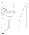
図3は、Aに沿った装置1の外側図を示し、図3中、振幅Cの特性が、所望の動作中に励起される振動のBに沿った位置の関数として概略的に示されている。ソノトロード2の作業領域7における溶接面5の位置Iは、最大振幅を有する。位置IIには節面が配置されており、ここでは振幅が大幅に消失する。反力体3のソノトロード2と反対の方向を向く側にある位置IIIでは、反力体3は、同様に最大振幅を有して振動する。これにより、溶接面5から、節面内に配置されるべき保持棚状部23への距離は、所望の動作中に励起される振動の波長の4分の1となる。したがって、ソノトロード2は、たとえば、材料、形状、サイズなどの面において所望の動作周波数に整合するように実現されるべきである。このことは、たとえばコンバータ11および反力体3などの残りの部品にも当てはまる。これにより、全体的に、装置1により、所望の動作中に励起される振動に半波長を有する共振器が得られる。
FIG. 3 shows an outer view of the
Claims (19)
細長いソノトロードヘッド(4)を有する1つのソノトロード(2)を備え、前記ソノトロードヘッド(4)上には、前記ソノトロードヘッド(4)の長手方向に向けられた細長い溶接面(5)が存在し、前記装置(1)はさらに、
作用方向(B)に前記ソノトロード(2)の超音波振動を励起するための少なくとも2つのコンバータ(11)を備え、
反動質量として1つの反力体(3)を備え、
前記少なくとも2つのコンバータ(11)は、前記ソノトロード(2)と前記反力体(3)との間に配置されることを特徴とする、装置(1)。 An apparatus (1) for ultrasonic welding,
A sonotrode (2) having an elongate sonotrode head (4), on the sonotrode head (4), an elongate weld surface oriented in the longitudinal direction of the sonotrode head (4) ( 5) and the device (1) further comprises
Comprising at least two converters (11) for exciting ultrasonic vibrations of the sonotrode (2) in the direction of action (B),
It has one reaction force body (3) as a reaction mass,
Device (1), characterized in that the at least two converters (11) are arranged between the sonotrode (2) and the reaction force body (3).
Applications Claiming Priority (3)
| Application Number | Priority Date | Filing Date | Title |
|---|---|---|---|
| EP20130162831 EP2789450A1 (en) | 2013-04-09 | 2013-04-09 | Device for welding by means of ultrasound |
| EP13162831.5 | 2013-04-09 | ||
| PCT/EP2014/055288 WO2014166702A1 (en) | 2013-04-09 | 2014-03-17 | Apparatus for ultrasonic welding |
Publications (3)
| Publication Number | Publication Date |
|---|---|
| JP2016522123A JP2016522123A (en) | 2016-07-28 |
| JP2016522123A5 JP2016522123A5 (en) | 2017-04-20 |
| JP6364475B2 true JP6364475B2 (en) | 2018-07-25 |
Family
ID=48082979
Family Applications (1)
| Application Number | Title | Priority Date | Filing Date |
|---|---|---|---|
| JP2016506826A Expired - Fee Related JP6364475B2 (en) | 2013-04-09 | 2014-03-17 | Equipment for ultrasonic welding |
Country Status (5)
| Country | Link |
|---|---|
| US (1) | US9950823B2 (en) |
| EP (2) | EP2789450A1 (en) |
| JP (1) | JP6364475B2 (en) |
| CN (1) | CN105163926B (en) |
| WO (1) | WO2014166702A1 (en) |
Families Citing this family (6)
| Publication number | Priority date | Publication date | Assignee | Title |
|---|---|---|---|---|
| EP3205478A1 (en) * | 2016-02-10 | 2017-08-16 | Ilapak Italia S.p.A. | Ultrasound welding device, in particular for welding flexible packages, optionally made of a plastic material and machine for packaging food products provided with such an ultrasound welding device |
| DE102016116429A1 (en) | 2016-09-02 | 2018-03-08 | Herrmann Ultraschalltechnik Gmbh & Co. Kg | Ultrasonic vibration system with lateral surface support |
| JP6897035B2 (en) * | 2016-09-13 | 2021-06-30 | 凸版印刷株式会社 | Anvil and ultrasonic sealing equipment |
| US10052714B2 (en) | 2016-10-14 | 2018-08-21 | Sonics & Materials, Inc. | Ultrasonic welding device with dual converters |
| US10913211B2 (en) | 2017-05-30 | 2021-02-09 | Campbell Soup Company | High rate ultrasonic sealer |
| DE102018108979A1 (en) * | 2018-04-16 | 2019-10-17 | Branson Ultraschall Niederlassung Der Emerson Technologies Gmbh & Co. Ohg | A vibration welding apparatus, method of joining at least two elongate members by vibration welding, and a method of manufacturing the vibration welding apparatus |
Family Cites Families (17)
| Publication number | Priority date | Publication date | Assignee | Title |
|---|---|---|---|---|
| DE1427629A1 (en) | 1961-02-01 | 1969-06-19 | Ransburg Electro Coating Corp | Atomizer for use in an electrostatic atomization system for covering objects |
| DE1427329A1 (en) * | 1962-09-29 | 1969-01-16 | Lehfeldt & Co Gmbh Dr | Process to achieve an ultrasonic weld joint |
| US4764907A (en) | 1986-04-30 | 1988-08-16 | Allied Corporation | Underwater transducer |
| SE505864C2 (en) * | 1993-03-19 | 1997-10-20 | Tetra Laval Holdings & Finance | Device for ultrasonic sealing |
| DE29503122U1 (en) * | 1995-02-24 | 1995-04-27 | Sonotronic Nagel Gmbh | Sonotrode |
| SE9502226L (en) * | 1995-06-19 | 1996-12-20 | Tetra Laval Holdings & Finance | Device at a drive for an ultrasonic sealing device |
| DE69926758T2 (en) * | 1998-03-23 | 2006-03-30 | Shikoku Kakoki Co., Ltd. | ULTRASOUND SIEGLER |
| JP4316053B2 (en) * | 1999-07-05 | 2009-08-19 | 四国化工機株式会社 | Ultrasonic sealing device |
| JP4282179B2 (en) * | 1999-09-30 | 2009-06-17 | 四国化工機株式会社 | Ultrasonic sealing device |
| JP4603122B2 (en) * | 2000-02-23 | 2010-12-22 | 四国化工機株式会社 | Ultrasonic sealing device |
| DE102005038344A1 (en) * | 2005-08-13 | 2007-02-15 | Tetra Laval Holdings & Finance S.A. | Device for ultrasonic machining of workpieces |
| US7718022B2 (en) * | 2008-05-15 | 2010-05-18 | 3M Innovative Properties Company | Resonant nodal mount for linear ultrasonic horns |
| CN101396866B (en) * | 2008-11-12 | 2012-02-22 | 大连理工大学 | Absorption ultrasonic tool head applied for connecting the polymers micro-devices |
| EP2368694A1 (en) | 2010-03-22 | 2011-09-28 | Tetra Laval Holdings & Finance S.A. | Sonotrode |
| US8591679B1 (en) * | 2011-12-13 | 2013-11-26 | Rinco Ultrasonics USA, Inc. | Retrofit of a form-fill-seal machine heat station with an advanced ultrasonic welding kit |
| US8689850B2 (en) * | 2010-10-26 | 2014-04-08 | Rinco Ultrasonics, Inc. | Pedestal mounted ultrasonic welding device |
| US9545751B2 (en) * | 2010-10-26 | 2017-01-17 | Rinco Ultrasonics USA, Inc. | Pedestal-mounted ultrasonic welding device |
-
2013
- 2013-04-09 EP EP20130162831 patent/EP2789450A1/en not_active Withdrawn
-
2014
- 2014-03-17 US US14/782,378 patent/US9950823B2/en not_active Expired - Fee Related
- 2014-03-17 EP EP14710317.0A patent/EP2983891B1/en active Active
- 2014-03-17 CN CN201480020349.XA patent/CN105163926B/en not_active Expired - Fee Related
- 2014-03-17 JP JP2016506826A patent/JP6364475B2/en not_active Expired - Fee Related
- 2014-03-17 WO PCT/EP2014/055288 patent/WO2014166702A1/en active Application Filing
Also Published As
| Publication number | Publication date |
|---|---|
| CN105163926A (en) | 2015-12-16 |
| US20160052658A1 (en) | 2016-02-25 |
| CN105163926B (en) | 2017-09-12 |
| JP2016522123A (en) | 2016-07-28 |
| EP2789450A1 (en) | 2014-10-15 |
| EP2983891B1 (en) | 2017-05-24 |
| EP2983891A1 (en) | 2016-02-17 |
| US9950823B2 (en) | 2018-04-24 |
| WO2014166702A1 (en) | 2014-10-16 |
Similar Documents
| Publication | Publication Date | Title |
|---|---|---|
| JP6364475B2 (en) | Equipment for ultrasonic welding | |
| US9662680B2 (en) | Ultrasonic transducer | |
| US3370186A (en) | Ultrasonic transducers | |
| JP3647058B2 (en) | Ultrasonic sealing device | |
| JP5583179B2 (en) | Bonding equipment | |
| CN102802920A (en) | Sonotrode | |
| CN107921482A (en) | The holding structure of ultrasonic vibration transmission mechanism | |
| WO2007020177A3 (en) | Piezoelectric actuator for an ultrasonic motor | |
| CN105408089A (en) | Ultrasonic welding apparatus having a plurality of sonotrodes | |
| JP2016137720A (en) | Screen printing | |
| JPH10501670A (en) | Piezoelectric ultrasonic transducer | |
| JP2004312119A (en) | Ultrasonic transducer | |
| KR20170057658A (en) | High efficiency ultrasonic vibrator | |
| KR101597560B1 (en) | Ultrasonic wave-generating device | |
| JP6774812B2 (en) | Ultrasonic bonding device | |
| JP6909333B2 (en) | Ultrasonic bonding device | |
| JPH02199994A (en) | Frequency variable vibrator | |
| JP2014172083A (en) | Booster horn and ultrasonic welder using booster horn | |
| JP2014168736A (en) | Bolt fastening langevin type vibrator and ultrasonic welder using bolt fastening langevin type vibrator | |
| KR102159856B1 (en) | Ultrasonic device having large radiating area | |
| CN212397193U (en) | Ultrasonic transducer | |
| JP6554698B2 (en) | Ultrasonic composite vibrator | |
| WO2013122048A1 (en) | Ultrasonic generation apparatus | |
| RU6352U1 (en) | ELECTROMECHANICAL CONVERTER | |
| JP2015047599A (en) | Focused ultrasonic wave generator |
Legal Events
| Date | Code | Title | Description |
|---|---|---|---|
| A521 | Request for written amendment filed |
Free format text: JAPANESE INTERMEDIATE CODE: A523 Effective date: 20170314 |
|
| A621 | Written request for application examination |
Free format text: JAPANESE INTERMEDIATE CODE: A621 Effective date: 20170314 |
|
| A977 | Report on retrieval |
Free format text: JAPANESE INTERMEDIATE CODE: A971007 Effective date: 20171124 |
|
| A131 | Notification of reasons for refusal |
Free format text: JAPANESE INTERMEDIATE CODE: A131 Effective date: 20171205 |
|
| A521 | Request for written amendment filed |
Free format text: JAPANESE INTERMEDIATE CODE: A523 Effective date: 20180301 |
|
| TRDD | Decision of grant or rejection written | ||
| A01 | Written decision to grant a patent or to grant a registration (utility model) |
Free format text: JAPANESE INTERMEDIATE CODE: A01 Effective date: 20180605 |
|
| A61 | First payment of annual fees (during grant procedure) |
Free format text: JAPANESE INTERMEDIATE CODE: A61 Effective date: 20180702 |
|
| R150 | Certificate of patent or registration of utility model |
Ref document number: 6364475 Country of ref document: JP Free format text: JAPANESE INTERMEDIATE CODE: R150 |
|
| LAPS | Cancellation because of no payment of annual fees |