JP6328245B2 - Air conditioner - Google Patents

Air conditioner Download PDF

Info

Publication number
JP6328245B2
JP6328245B2 JP2016538367A JP2016538367A JP6328245B2 JP 6328245 B2 JP6328245 B2 JP 6328245B2 JP 2016538367 A JP2016538367 A JP 2016538367A JP 2016538367 A JP2016538367 A JP 2016538367A JP 6328245 B2 JP6328245 B2 JP 6328245B2
Authority
JP
Japan
Prior art keywords
refrigerant
indoor
unit
relay
indoor unit
Prior art date
Legal status (The legal status is an assumption and is not a legal conclusion. Google has not performed a legal analysis and makes no representation as to the accuracy of the status listed.)
Active
Application number
JP2016538367A
Other languages
Japanese (ja)
Other versions
JPWO2016017643A1 (en
Inventor
直史 竹中
直史 竹中
若本 慎一
慎一 若本
祐治 本村
祐治 本村
森本 修
修 森本
博文 ▲高▼下
博文 ▲高▼下
山下 浩司
浩司 山下
Current Assignee (The listed assignees may be inaccurate. Google has not performed a legal analysis and makes no representation or warranty as to the accuracy of the list.)
Mitsubishi Electric Corp
Original Assignee
Mitsubishi Electric Corp
Priority date (The priority date is an assumption and is not a legal conclusion. Google has not performed a legal analysis and makes no representation as to the accuracy of the date listed.)
Filing date
Publication date
Application filed by Mitsubishi Electric Corp filed Critical Mitsubishi Electric Corp
Publication of JPWO2016017643A1 publication Critical patent/JPWO2016017643A1/en
Application granted granted Critical
Publication of JP6328245B2 publication Critical patent/JP6328245B2/en
Active legal-status Critical Current
Anticipated expiration legal-status Critical

Links

Images

Classifications

    • FMECHANICAL ENGINEERING; LIGHTING; HEATING; WEAPONS; BLASTING
    • F24HEATING; RANGES; VENTILATING
    • F24FAIR-CONDITIONING; AIR-HUMIDIFICATION; VENTILATION; USE OF AIR CURRENTS FOR SCREENING
    • F24F11/00Control or safety arrangements
    • F24F11/89Arrangement or mounting of control or safety devices
    • FMECHANICAL ENGINEERING; LIGHTING; HEATING; WEAPONS; BLASTING
    • F24HEATING; RANGES; VENTILATING
    • F24FAIR-CONDITIONING; AIR-HUMIDIFICATION; VENTILATION; USE OF AIR CURRENTS FOR SCREENING
    • F24F11/00Control or safety arrangements
    • F24F11/30Control or safety arrangements for purposes related to the operation of the system, e.g. for safety or monitoring
    • F24F11/32Responding to malfunctions or emergencies
    • F24F11/36Responding to malfunctions or emergencies to leakage of heat-exchange fluid
    • FMECHANICAL ENGINEERING; LIGHTING; HEATING; WEAPONS; BLASTING
    • F25REFRIGERATION OR COOLING; COMBINED HEATING AND REFRIGERATION SYSTEMS; HEAT PUMP SYSTEMS; MANUFACTURE OR STORAGE OF ICE; LIQUEFACTION SOLIDIFICATION OF GASES
    • F25BREFRIGERATION MACHINES, PLANTS OR SYSTEMS; COMBINED HEATING AND REFRIGERATION SYSTEMS; HEAT PUMP SYSTEMS
    • F25B13/00Compression machines, plants or systems, with reversible cycle
    • FMECHANICAL ENGINEERING; LIGHTING; HEATING; WEAPONS; BLASTING
    • F25REFRIGERATION OR COOLING; COMBINED HEATING AND REFRIGERATION SYSTEMS; HEAT PUMP SYSTEMS; MANUFACTURE OR STORAGE OF ICE; LIQUEFACTION SOLIDIFICATION OF GASES
    • F25BREFRIGERATION MACHINES, PLANTS OR SYSTEMS; COMBINED HEATING AND REFRIGERATION SYSTEMS; HEAT PUMP SYSTEMS
    • F25B41/00Fluid-circulation arrangements
    • F25B41/20Disposition of valves, e.g. of on-off valves or flow control valves
    • F25B41/24Arrangement of shut-off valves for disconnecting a part of the refrigerant cycle, e.g. an outdoor part
    • FMECHANICAL ENGINEERING; LIGHTING; HEATING; WEAPONS; BLASTING
    • F25REFRIGERATION OR COOLING; COMBINED HEATING AND REFRIGERATION SYSTEMS; HEAT PUMP SYSTEMS; MANUFACTURE OR STORAGE OF ICE; LIQUEFACTION SOLIDIFICATION OF GASES
    • F25BREFRIGERATION MACHINES, PLANTS OR SYSTEMS; COMBINED HEATING AND REFRIGERATION SYSTEMS; HEAT PUMP SYSTEMS
    • F25B49/00Arrangement or mounting of control or safety devices
    • F25B49/005Arrangement or mounting of control or safety devices of safety devices
    • FMECHANICAL ENGINEERING; LIGHTING; HEATING; WEAPONS; BLASTING
    • F24HEATING; RANGES; VENTILATING
    • F24FAIR-CONDITIONING; AIR-HUMIDIFICATION; VENTILATION; USE OF AIR CURRENTS FOR SCREENING
    • F24F3/00Air-conditioning systems in which conditioned primary air is supplied from one or more central stations to distributing units in the rooms or spaces where it may receive secondary treatment; Apparatus specially designed for such systems
    • F24F3/06Air-conditioning systems in which conditioned primary air is supplied from one or more central stations to distributing units in the rooms or spaces where it may receive secondary treatment; Apparatus specially designed for such systems characterised by the arrangements for the supply of heat-exchange fluid for the subsequent treatment of primary air in the room units
    • F24F3/065Air-conditioning systems in which conditioned primary air is supplied from one or more central stations to distributing units in the rooms or spaces where it may receive secondary treatment; Apparatus specially designed for such systems characterised by the arrangements for the supply of heat-exchange fluid for the subsequent treatment of primary air in the room units with a plurality of evaporators or condensers
    • FMECHANICAL ENGINEERING; LIGHTING; HEATING; WEAPONS; BLASTING
    • F25REFRIGERATION OR COOLING; COMBINED HEATING AND REFRIGERATION SYSTEMS; HEAT PUMP SYSTEMS; MANUFACTURE OR STORAGE OF ICE; LIQUEFACTION SOLIDIFICATION OF GASES
    • F25BREFRIGERATION MACHINES, PLANTS OR SYSTEMS; COMBINED HEATING AND REFRIGERATION SYSTEMS; HEAT PUMP SYSTEMS
    • F25B2313/00Compression machines, plants or systems with reversible cycle not otherwise provided for
    • F25B2313/023Compression machines, plants or systems with reversible cycle not otherwise provided for using multiple indoor units
    • F25B2313/0231Compression machines, plants or systems with reversible cycle not otherwise provided for using multiple indoor units with simultaneous cooling and heating
    • FMECHANICAL ENGINEERING; LIGHTING; HEATING; WEAPONS; BLASTING
    • F25REFRIGERATION OR COOLING; COMBINED HEATING AND REFRIGERATION SYSTEMS; HEAT PUMP SYSTEMS; MANUFACTURE OR STORAGE OF ICE; LIQUEFACTION SOLIDIFICATION OF GASES
    • F25BREFRIGERATION MACHINES, PLANTS OR SYSTEMS; COMBINED HEATING AND REFRIGERATION SYSTEMS; HEAT PUMP SYSTEMS
    • F25B2313/00Compression machines, plants or systems with reversible cycle not otherwise provided for
    • F25B2313/023Compression machines, plants or systems with reversible cycle not otherwise provided for using multiple indoor units
    • F25B2313/0233Compression machines, plants or systems with reversible cycle not otherwise provided for using multiple indoor units in parallel arrangements
    • FMECHANICAL ENGINEERING; LIGHTING; HEATING; WEAPONS; BLASTING
    • F25REFRIGERATION OR COOLING; COMBINED HEATING AND REFRIGERATION SYSTEMS; HEAT PUMP SYSTEMS; MANUFACTURE OR STORAGE OF ICE; LIQUEFACTION SOLIDIFICATION OF GASES
    • F25BREFRIGERATION MACHINES, PLANTS OR SYSTEMS; COMBINED HEATING AND REFRIGERATION SYSTEMS; HEAT PUMP SYSTEMS
    • F25B2313/00Compression machines, plants or systems with reversible cycle not otherwise provided for
    • F25B2313/027Compression machines, plants or systems with reversible cycle not otherwise provided for characterised by the reversing means
    • F25B2313/02741Compression machines, plants or systems with reversible cycle not otherwise provided for characterised by the reversing means using one four-way valve
    • FMECHANICAL ENGINEERING; LIGHTING; HEATING; WEAPONS; BLASTING
    • F25REFRIGERATION OR COOLING; COMBINED HEATING AND REFRIGERATION SYSTEMS; HEAT PUMP SYSTEMS; MANUFACTURE OR STORAGE OF ICE; LIQUEFACTION SOLIDIFICATION OF GASES
    • F25BREFRIGERATION MACHINES, PLANTS OR SYSTEMS; COMBINED HEATING AND REFRIGERATION SYSTEMS; HEAT PUMP SYSTEMS
    • F25B2500/00Problems to be solved
    • F25B2500/05Cost reduction
    • FMECHANICAL ENGINEERING; LIGHTING; HEATING; WEAPONS; BLASTING
    • F25REFRIGERATION OR COOLING; COMBINED HEATING AND REFRIGERATION SYSTEMS; HEAT PUMP SYSTEMS; MANUFACTURE OR STORAGE OF ICE; LIQUEFACTION SOLIDIFICATION OF GASES
    • F25BREFRIGERATION MACHINES, PLANTS OR SYSTEMS; COMBINED HEATING AND REFRIGERATION SYSTEMS; HEAT PUMP SYSTEMS
    • F25B2500/00Problems to be solved
    • F25B2500/22Preventing, detecting or repairing leaks of refrigeration fluids
    • F25B2500/222Detecting refrigerant leaks
    • FMECHANICAL ENGINEERING; LIGHTING; HEATING; WEAPONS; BLASTING
    • F25REFRIGERATION OR COOLING; COMBINED HEATING AND REFRIGERATION SYSTEMS; HEAT PUMP SYSTEMS; MANUFACTURE OR STORAGE OF ICE; LIQUEFACTION SOLIDIFICATION OF GASES
    • F25BREFRIGERATION MACHINES, PLANTS OR SYSTEMS; COMBINED HEATING AND REFRIGERATION SYSTEMS; HEAT PUMP SYSTEMS
    • F25B2600/00Control issues
    • F25B2600/25Control of valves
    • F25B2600/2519On-off valves

Description

本発明は、冷凍サイクルを備える空気調和装置に関する。   The present invention relates to an air conditioner including a refrigeration cycle.

空気調和装置は、例えば建物外に配置された熱源機である室外機と、建物内に配置された室内機とが配管により接続された冷媒回路を備え、この冷媒回路に冷媒が循環している(例えば、特許文献1〜4参照)。そして、空気調和装置において、冷媒の放熱又は吸熱を利用して、空調対象空間の空気を加熱又は冷却することによって、空調対象空間の暖房又は冷房が行われる。ここで、例えば何らかの原因によって、室内空間に配置された室内機から冷媒が漏洩した場合、その冷媒が引火性又は有毒性等を有する種類であると、例えば人体への影響及び安全性の観点から極めて問題である。また、その漏洩した冷媒が、例えば人体に無害であっても、室内空間に漏れた冷媒によって、その冷媒の濃度が増して、室内空間における酸素濃度が低下し、その結果、人体に悪影響を及ぼす虞もある。室内機が複数台接続され、室外機と室内機とを接続する配管が100mに及ぶようなマルチエアコンは、多量の冷媒が充填されているため、冷媒の漏洩を防止する対策が、特に必要である。   An air conditioner includes a refrigerant circuit in which an outdoor unit that is a heat source unit arranged outside a building and an indoor unit arranged inside the building are connected by piping, and the refrigerant circulates in the refrigerant circuit. (For example, see Patent Documents 1 to 4). And in an air conditioning apparatus, heating or cooling of an air-conditioning object space is performed by heating or cooling the air of an air-conditioning object space using heat dissipation or heat absorption of a refrigerant. Here, for example, when a refrigerant leaks from an indoor unit arranged in the indoor space for some reason, the refrigerant is of a type having flammability or toxicity, for example, from the viewpoint of influence on human body and safety It is extremely a problem. Further, even if the leaked refrigerant is harmless to the human body, for example, the refrigerant leaked into the indoor space increases the concentration of the refrigerant and decreases the oxygen concentration in the indoor space, resulting in adverse effects on the human body. There is also a fear. A multi-air conditioner with multiple indoor units connected and a pipe connecting the outdoor unit to the indoor unit extending over 100m is filled with a large amount of refrigerant, so measures to prevent refrigerant leakage are particularly necessary. is there.

そこで、冷媒センサと配管遮断弁とを備えた空気調和装置が提案されている。この空気調和装置は、冷媒センサによって、冷媒の漏洩が検出されると、冷媒が漏洩していることがリモートコントローラに表示されることによって、室内にいる人が冷媒の漏洩を知ることができる。また、冷媒センサによって、冷媒の漏洩が検出されると、空気調和装置の制御部が配管遮断弁を閉じることによって、室内に漏洩する冷媒の量を抑えることができる。   Therefore, an air conditioner including a refrigerant sensor and a pipe shutoff valve has been proposed. In the air conditioner, when refrigerant leakage is detected by the refrigerant sensor, the remote controller displays that the refrigerant is leaking, so that a person in the room can know the refrigerant leakage. In addition, when refrigerant leakage is detected by the refrigerant sensor, the control unit of the air conditioner closes the pipe shutoff valve, thereby suppressing the amount of refrigerant leaking into the room.

特許文献1には、二酸化炭素(CO)を冷媒として用いた空気調和装置が開示されている。この特許文献1は、室内に設置されたCOセンサが所定量のCOを検出した場合、室内機のガス管に設置された電磁弁を閉止し、また、室内機の液管に設置されたCOの流量を制御する電動弁を閉止する。更に、COが漏洩していることが、室内のリモートコントローラに表示される。Patent Document 1 discloses an air conditioner using carbon dioxide (CO 2 ) as a refrigerant. In Patent Document 1, when a CO 2 sensor installed in a room detects a predetermined amount of CO 2 , the electromagnetic valve installed in the gas pipe of the indoor unit is closed, and is installed in the liquid pipe of the indoor unit. The motorized valve that controls the flow rate of CO 2 is closed. Furthermore, the fact that CO 2 is leaking is displayed on the remote controller in the room.

特許文献2には、冷暖混在運転が可能なマルチエアコンが開示されている。冷暖同時運転において、暖房運転が行われている室内機が停止したときに、室内機に流通していた暖かいガス冷媒が、流量制御弁を通って、冷房運転が行われている室内機に引き返し、冷媒が加熱されて、室内機における冷房能力が低下してしまう。特許文献2は、複数の室内機の各液管が合流する分岐部に設けられた電磁弁を用いて、このような課題を解消しようとするものである。   Patent Document 2 discloses a multi-air conditioner that can perform a cooling and heating mixed operation. In the simultaneous cooling and heating operation, when the indoor unit in which the heating operation is performed stops, the warm gas refrigerant circulating in the indoor unit passes back to the indoor unit in which the cooling operation is performed through the flow control valve. The refrigerant is heated, and the cooling capacity of the indoor unit is reduced. Patent Document 2 intends to solve such a problem by using an electromagnetic valve provided at a branch portion where the liquid pipes of a plurality of indoor units merge.

特許文献3には、流体が双方向に流通する流体回路で使用することができ、且つ、流体の特定方向への通過を適切に防止することができる冷媒遮断弁が開示されており、その具体的な構造が開示されている。   Patent Document 3 discloses a refrigerant shut-off valve that can be used in a fluid circuit in which fluid flows in both directions and that can appropriately prevent passage of fluid in a specific direction. A typical structure is disclosed.

特許文献4には、複数の室内機の各液管及び各ガス管が合流する中継装置(分岐装置)を備えるマルチエアコンが開示されている。この特許文献4は、中継装置において、各液管毎に、夫々遮断弁が設けられており、各ガス管毎に、夫々遮断弁が設けられている。そして、冷媒が漏洩した室内機に接続された液管及びガス管に設けられた各遮断弁を閉じることによって、そのほかの室内機等から、冷媒が漏洩した室内機に冷媒が流通することを防止しようとするものである。   Patent Document 4 discloses a multi air conditioner including a relay device (branching device) in which each liquid pipe and each gas pipe of a plurality of indoor units merge. According to Patent Document 4, in the relay device, a shut-off valve is provided for each liquid pipe, and a shut-off valve is provided for each gas pipe. Then, by closing each shutoff valve provided in the liquid pipe and gas pipe connected to the indoor unit where the refrigerant has leaked, the refrigerant is prevented from flowing from the other indoor units to the indoor unit in which the refrigerant has leaked. It is something to try.

特開2010−7998号公報(図1)Japanese Patent Laying-Open No. 2010-7998 (FIG. 1) 特開平9−4940号公報(図1)Japanese Patent Laid-Open No. 9-4940 (FIG. 1) 特開2012−57676号公報(図1)JP 2012-57676 A (FIG. 1) 国際公開第2012/160598号(図2)International Publication No. 2012/160598 (Figure 2)

流量を制御する流量制御弁は、ニードルを上下させることによって、流路抵抗が連続的に変化するものである。しかし、特許文献2に記載されているように、流量制御弁は、全閉状態であっても、完全に閉止することはできず、僅かに開いている。このため、冷媒を完全に遮断することができない。   The flow rate control valve for controlling the flow rate is such that the flow path resistance changes continuously by moving the needle up and down. However, as described in Patent Document 2, the flow control valve cannot be completely closed even in the fully closed state, and is slightly opened. For this reason, a refrigerant | coolant cannot be interrupted | blocked completely.

特許文献1に開示された空気調和装置は、冷媒が漏洩した室内機において、その室内機の液側配管に設けられた電磁弁を閉止して、回路全体の冷媒が、漏洩が発生した室内機に流入することを防止しようとするものである。しかし、上記のとおり、電磁弁は、完全に閉止することはできないため、冷媒が、漏洩が発生した室内機に流入し続ける。また、ガス側配管においては、電磁弁を閉止することによって、回路全体の冷媒が、漏洩が発生した室内機に流入することを防止しようとしているが、電磁弁は、概して設計された方向と逆方向に圧力がかかった場合、正常に動作しない。例えば、冷房運転において、ガス側配管には、室内機から室外機に向けて冷媒が流通するため、室内機の側の圧力が高い状態で正常に動作するように、電磁弁が取り付けられる。しかし、冷媒が漏洩した場合、冷媒が漏洩した室内機の圧力が大気圧にまで低下するため、設計された方向と逆方向に圧力がかかり、電磁弁が正常に動作しない。このため、冷媒を遮断することができない。   The air conditioner disclosed in Patent Document 1 is an indoor unit in which leakage of refrigerant in the entire circuit is caused by closing a solenoid valve provided in a liquid side pipe of the indoor unit in an indoor unit in which refrigerant has leaked. It is intended to prevent inflow. However, as described above, since the solenoid valve cannot be completely closed, the refrigerant continues to flow into the indoor unit where leakage has occurred. In the gas side piping, the solenoid valve is closed to prevent the refrigerant in the entire circuit from flowing into the leaked indoor unit. However, the solenoid valve is generally opposite to the designed direction. If pressure is applied in the direction, it will not work properly. For example, in the cooling operation, the refrigerant circulates from the indoor unit to the outdoor unit in the gas side pipe. Therefore, an electromagnetic valve is attached so that the gas side pipe operates normally with a high pressure on the indoor unit side. However, when the refrigerant leaks, the pressure of the indoor unit from which the refrigerant has leaked drops to atmospheric pressure, so pressure is applied in the direction opposite to the designed direction, and the solenoid valve does not operate normally. For this reason, the refrigerant cannot be shut off.

なお、ガス側配管においては、特許文献3に開示された冷媒遮断弁、即ち、流体が双方向に流通する流体回路で使用することができ、且つ、流体の特定方向への通過を適切に防止することができるものを適用すれば、冷媒の流入を阻止することはできるが、液側配管においては、依然として、問題は解消されない。   In addition, in the gas side piping, it can be used in the refrigerant shut-off valve disclosed in Patent Document 3, that is, a fluid circuit in which fluid flows in both directions, and appropriately prevents passage of fluid in a specific direction. If what can be applied is applied, the inflow of the refrigerant can be prevented, but the problem still remains in the liquid side piping.

また、特許文献4に開示された空気調和装置は、遮断弁が、室内機1台当たり2個必要である。これにより、コストが上昇し、アクチュエータの制御台数が増加して、制御が複雑になる。   Moreover, the air conditioner disclosed in Patent Document 4 requires two shut-off valves per indoor unit. This increases the cost, increases the number of actuators to be controlled, and makes the control complicated.

本発明は、上記のような課題を背景としてなされたもので、冷媒遮断弁の使用個数を低減して、コスト上昇及び制御煩雑化を抑制する空気調和装置を提供するものである。   The present invention has been made against the background of the above problems, and provides an air conditioner that reduces the number of refrigerant shut-off valves used and suppresses cost increase and control complexity.

本発明に係る空気調和装置は、圧縮機及び室外熱交換器を有する室外機と、夫々室内熱交換器を有する複数の室内機と、室外機から供給される冷媒を複数の室内機に分配するものであり、複数の室内機における各液側配管が合流する第1の分岐部と、双方向における冷媒の流通を制御し複数の室内機の台数未満の台数だけ第1の分岐部に設けられた冷媒遮断弁と、を有する中継機と、を備え、第1の分岐部は、室内機から中継機への冷媒の流通を許容する経路、及び、中継機から室内機への冷媒の流通を許容する経路で構成されており、冷媒遮断弁は、中継機から室内機への冷媒の流通を許容する経路において、複数の室内機に分岐する分岐点の上流側に設けられているAn air conditioner according to the present invention distributes an outdoor unit having a compressor and an outdoor heat exchanger, a plurality of indoor units each having an indoor heat exchanger, and a refrigerant supplied from the outdoor unit to the plurality of indoor units. The first branching section where the liquid side pipes in the plurality of indoor units join together, and the first branching section controls the flow of the refrigerant in both directions and is less than the number of the plurality of indoor units. A relay unit having a refrigerant shut-off valve, and the first branching unit allows passage of the refrigerant from the indoor unit to the relay unit, and allows the refrigerant to flow from the relay unit to the indoor unit. The refrigerant shut-off valve is provided on the upstream side of a branch point that branches into a plurality of indoor units in a path that allows the refrigerant to flow from the relay unit to the indoor unit .

本発明によれば、室内機の液側配管に接続される冷媒遮断弁が、室内機の台数未満の台数だけ備わっているため、コスト低減及び制御簡略化を両立することができる。   According to the present invention, since the number of refrigerant shut-off valves connected to the liquid side pipe of the indoor unit is less than the number of indoor units, both cost reduction and simplification of control can be achieved.

本発明の実施の形態1に係る空気調和装置100を示す回路図である。It is a circuit diagram which shows the air conditioning apparatus 100 which concerns on Embodiment 1 of this invention. 本発明の実施の形態1における冷房運転を示す回路図である。It is a circuit diagram which shows the air_conditionaing | cooling operation in Embodiment 1 of this invention. 本発明の実施の形態1における冷房運転のP−h線図である。It is a Ph diagram of the cooling operation in Embodiment 1 of the present invention. 本発明の実施の形態1における暖房運転を示す回路図である。It is a circuit diagram which shows the heating operation in Embodiment 1 of this invention. 本発明の実施の形態1における暖房運転のP−h線図である。It is a Ph diagram of heating operation in Embodiment 1 of the present invention. 本発明の実施の形態1における冷媒回収運転を示す回路図である。It is a circuit diagram which shows the refrigerant | coolant collection | recovery driving | operation in Embodiment 1 of this invention. 本発明の実施の形態1における冷媒回収運転のP−h線図である。It is a Ph diagram of the refrigerant recovery operation in Embodiment 1 of the present invention. 本発明の実施の形態2に係る空気調和装置101aを示す回路図である。It is a circuit diagram which shows the air conditioning apparatus 101a which concerns on Embodiment 2 of this invention. 本発明の実施の形態2の変形例に係る空気調和装置101を示す回路図である。It is a circuit diagram which shows the air conditioning apparatus 101 which concerns on the modification of Embodiment 2 of this invention. 本発明の実施の形態2の変形例における室内中継流路制御弁10aの構造を示す図である。It is a figure which shows the structure of the indoor relay flow path control valve 10a in the modification of Embodiment 2 of this invention. 本発明の実施の形態3に係る空気調和装置102を示す回路図である。It is a circuit diagram which shows the air conditioning apparatus 102 which concerns on Embodiment 3 of this invention. 本発明の実施の形態3における冷房主体運転を示す回路図である。It is a circuit diagram which shows the cooling main operation | movement in Embodiment 3 of this invention. 本発明の実施の形態3における冷房主体運転のP−h線図である。It is a Ph diagram of cooling main operation in Embodiment 3 of the present invention. 本発明の実施の形態3における暖房主体運転を示す回路図である。It is a circuit diagram which shows the heating main driving | operation in Embodiment 3 of this invention. 本発明の実施の形態3における暖房主体運転のP−h線図である。It is a Ph diagram of heating main operation in Embodiment 3 of the present invention. 本発明の実施の形態3における冷媒回収運転を示す回路図である。It is a circuit diagram which shows the refrigerant | coolant collection | recovery driving | operation in Embodiment 3 of this invention. 本発明の実施の形態3における冷媒回収運転のP−h線図である。It is a Ph diagram of refrigerant recovery operation in Embodiment 3 of the present invention. 本発明の実施の形態4に係る空気調和装置103を示す回路図である。It is a circuit diagram which shows the air conditioning apparatus 103 which concerns on Embodiment 4 of this invention. 本発明の実施の形態4における冷媒回収運転を示す回路図である。It is a circuit diagram which shows the refrigerant | coolant collection | recovery driving | operation in Embodiment 4 of this invention. 本発明の実施の形態4における冷媒回収運転のP−h線図である。It is a Ph diagram of refrigerant recovery operation in Embodiment 4 of the present invention. 本発明の実施の形態5に係る空気調和装置104を示す回路図である。It is a circuit diagram which shows the air conditioning apparatus 104 which concerns on Embodiment 5 of this invention. 本発明の実施の形態6に係る空気調和装置105を示す回路図である。It is a circuit diagram which shows the air conditioning apparatus 105 which concerns on Embodiment 6 of this invention.

以下、本発明に係る空気調和装置の実施の形態について、図面を参照しながら説明する。なお、以下に説明する実施の形態によって本発明が限定されるものではない。また、図1を含め、以下の図面では各構成部材の大きさの関係が実際のものとは異なる場合がある。   Hereinafter, embodiments of an air-conditioning apparatus according to the present invention will be described with reference to the drawings. The present invention is not limited to the embodiments described below. Moreover, in the following drawings including FIG. 1, the relationship of the size of each component may be different from the actual one.

実施の形態1.
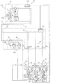
図1は、本発明の実施の形態1に係る空気調和装置100を示す回路図である。この図1に基づいて、空気調和装置100について説明する。図1に示すように、空気調和装置100は、室外機A(熱源機)と、夫々並列に接続された複数の室内機Xと、室外機Aと室内機Xとの間に介在する中継機Bとを備え、冷凍サイクルを構成している。室内機Xは、3台設けられており、夫々第1の室内機C、第2の室内機D及び第3の室内機Eである。なお、本実施の形態1では、室外機Aが1台設けられ、中継機Bが1台設けられ、室内機Xが3台設けられているが、室外機A、中継機B及び室内機Xの接続台数は、これらの台数に限定されるものではない。例えば、室外機Aが2台以上設けられ、中継機Bが2台以上設けられ、並列に接続される室内機Xが2台以上設けられていてもよい。
Embodiment 1 FIG.
FIG. 1 is a circuit diagram showing an air-conditioning apparatus 100 according to Embodiment 1 of the present invention. The air conditioner 100 will be described with reference to FIG. As shown in FIG. 1, the air conditioner 100 includes an outdoor unit A (heat source unit), a plurality of indoor units X connected in parallel, and a relay unit interposed between the outdoor unit A and the indoor unit X. B, and constitutes a refrigeration cycle. Three indoor units X are provided, which are a first indoor unit C, a second indoor unit D, and a third indoor unit E, respectively. In the first embodiment, one outdoor unit A is provided, one relay unit B is provided, and three indoor units X are provided. However, the outdoor unit A, the relay unit B, and the indoor unit X are provided. The number of connected devices is not limited to these numbers. For example, two or more outdoor units A may be provided, two or more relay units B may be provided, and two or more indoor units X connected in parallel may be provided.

室外機Aと中継機Bとは、第1の接続配管6及び第2の接続配管7によって接続されている。第1の接続配管6は、液冷媒が流通する液側配管となり、第2の接続配管7は、ガス冷媒が流通するガス側配管となる。   The outdoor unit A and the relay unit B are connected by a first connection pipe 6 and a second connection pipe 7. The first connection pipe 6 is a liquid side pipe through which the liquid refrigerant flows, and the second connection pipe 7 is a gas side pipe through which the gas refrigerant flows.

また、中継機Bと室内機Xとは、第1の室内機側接続配管6a及び第2の室内機側接続配管7aによって接続されている。第1の室内機側接続配管6aは、液冷媒が流通する液側配管となり、第2の室内機側接続配管7aは、ガス冷媒が流通するガス側配管となる。なお、第1の室内機Cには、第11の室内機側接続配管6c及び第21の室内機側接続配管7cが接続されており、第2の室内機Dには、第12の室内機側接続配管6d及び第22の室内機側接続配管7dが接続されており、第3の室内機Eには、第13の室内機側接続配管6e及び第23の室内機側接続配管7eが接続されている。   Moreover, the relay machine B and the indoor unit X are connected by the 1st indoor unit side connection piping 6a and the 2nd indoor unit side connection piping 7a. The first indoor unit side connection pipe 6a is a liquid side pipe through which liquid refrigerant flows, and the second indoor unit side connection pipe 7a is a gas side pipe through which gas refrigerant flows. The 11th indoor unit side connection pipe 6c and the 21st indoor unit side connection pipe 7c are connected to the first indoor unit C, and the 12th indoor unit is connected to the second indoor unit D. The side connection pipe 6d and the twenty-second indoor unit side connection pipe 7d are connected, and the thirteenth indoor unit side connection pipe 6e and the twenty-third indoor unit side connection pipe 7e are connected to the third indoor unit E. Has been.

空気調和装置100を構成する冷凍サイクルに使用される冷媒としては、フロン冷媒、例えばHFC系冷媒のR32、R125、R134a、又はこれらの混合冷媒のR410a、R407c、R404A等を使用することができる。また、冷媒は、HFO冷媒、例えばHFO−1234yf、HFO−1234ze(E)、HFO−1234ze(Z)等、CO冷媒、HC冷媒(例えばプロパン冷媒、イソブタン冷媒)、アンモニア冷媒、R32及びHFO−1234yfの混合冷媒といった上記冷媒の混合冷媒等でもよい。このように、冷媒としては、蒸気圧縮式のヒートポンプに使用される冷媒を使用すればよい。As the refrigerant used in the refrigeration cycle constituting the air conditioner 100, a fluorocarbon refrigerant such as R32, R125, R134a of HFC refrigerant, or R410a, R407c, R404A of these mixed refrigerants, etc. can be used. The refrigerant is HFO refrigerant such as HFO-1234yf, HFO-1234ze (E), HFO-1234ze (Z), etc., CO 2 refrigerant, HC refrigerant (for example, propane refrigerant, isobutane refrigerant), ammonia refrigerant, R32 and HFO- A mixed refrigerant of the above refrigerant such as a mixed refrigerant of 1234yf may be used. Thus, the refrigerant used in the vapor compression heat pump may be used as the refrigerant.

(室外機A)
室外機Aは、通常、ビル等の建物の外の空間、例えば屋上等に設置され、中継機Bを介して、室内機Xに冷熱又は温熱を供給するものである。なお、室外機Aの設置場所は室外に限られず、例えば換気口を備えた機械室等のような囲まれた空間でもよく、排気ダクトによって廃熱を建物の外に排気することができる場所であれば、建物の内部でもよい。
(Outdoor unit A)
The outdoor unit A is usually installed in a space outside a building such as a building, such as a rooftop, and supplies cold or warm heat to the indoor unit X via the relay unit B. The installation location of the outdoor unit A is not limited to the outside, but may be an enclosed space such as a machine room provided with a ventilation port, for example, where exhaust heat can be exhausted outside the building by an exhaust duct. If it is, it may be inside the building.

室外機Aは、冷媒を圧縮する圧縮機1と、冷媒の流通方向を切り替える四方弁からなる流路切替部2と、流体と冷媒との熱交換を行う室外熱交換器3と、液冷媒を貯留するアキュムレータ4と、室外制御部50とを備えている。圧縮機1、流路切替部2、室外熱交換器3及びアキュムレータ4は、第1の接続配管6及び第2の接続配管7によって、接続されている。また、室外熱交換器3の近傍には、冷媒と熱交換する流体の流量を制御する流量制御部である室外送風機3mが設けられている。   The outdoor unit A includes a compressor 1 that compresses refrigerant, a flow path switching unit 2 that includes a four-way valve that switches a refrigerant flow direction, an outdoor heat exchanger 3 that performs heat exchange between the fluid and the refrigerant, and liquid refrigerant. The accumulator 4 to store and the outdoor control part 50 are provided. The compressor 1, the flow path switching unit 2, the outdoor heat exchanger 3, and the accumulator 4 are connected by a first connection pipe 6 and a second connection pipe 7. Further, in the vicinity of the outdoor heat exchanger 3, an outdoor fan 3m is provided as a flow rate control unit that controls the flow rate of the fluid that exchanges heat with the refrigerant.

圧縮機1は、冷媒を吸入し、その冷媒を圧縮して高温高圧の状態にするものであり、例えば、容量制御可能なインバータ圧縮機等で構成することができる。また、流路切替部2は、暖房運転時における冷媒の流通方向と、冷房運転時における冷媒の流通方向とを切り替えるものである。室外熱交換器3は、暖房運転時には蒸発器として作用し、また、冷房運転時には凝縮器又は放熱器として作用するものである。そして、室外熱交換器3は、室外送風機3mから供給される流体(例えば空気)と冷媒との間で熱交換を行い、その冷媒を蒸発ガス化又は凝縮液化するものである。アキュムレータ4は、圧縮機1の吸入側に設けられており、暖房運転時における冷媒の流通量と冷房運転時における冷媒の流通量との相違がもたらす余剰冷媒を蓄え、過渡的な運転の変化がもたらす余剰冷媒を蓄えるものである。   The compressor 1 sucks refrigerant and compresses the refrigerant to a high temperature and high pressure state, and can be configured by, for example, an inverter compressor capable of capacity control. Further, the flow path switching unit 2 switches the refrigerant flow direction during the heating operation and the refrigerant flow direction during the cooling operation. The outdoor heat exchanger 3 acts as an evaporator during heating operation, and acts as a condenser or a radiator during cooling operation. The outdoor heat exchanger 3 exchanges heat between the fluid (for example, air) supplied from the outdoor fan 3m and the refrigerant, and evaporates or condenses the refrigerant. The accumulator 4 is provided on the suction side of the compressor 1, stores excess refrigerant caused by a difference between the refrigerant circulation amount during the heating operation and the refrigerant circulation amount during the cooling operation, and changes in transient operation occur. It stores excess refrigerant.

また、圧縮機1の吐出側の配管には、吐出圧力検出部31が設けられており、圧縮機1の吸入側の配管には、吸入圧力検出部32が設けられている。更に、室外熱交換器3の近傍には、室外温度検出部41が設けられている。そして、室外制御部50は、これらの吐出圧力検出部31、吸入圧力検出部32及び室外温度検出部41によって検出された圧力情報及び温度情報に基づいて、空気調和装置100の各構成を制御する。   Further, a discharge pressure detection unit 31 is provided in the discharge side piping of the compressor 1, and a suction pressure detection unit 32 is provided in the suction side piping of the compressor 1. Further, an outdoor temperature detector 41 is provided in the vicinity of the outdoor heat exchanger 3. And the outdoor control part 50 controls each structure of the air conditioning apparatus 100 based on the pressure information and temperature information which were detected by these discharge pressure detection part 31, the suction pressure detection part 32, and the outdoor temperature detection part 41. .

(中継機B)
中継機Bは、例えば建物の外部、又は室内空間とは別の空間である天井裏等の建物の内部に設置され、室外機Aから供給される冷熱又は温熱を室内機Xに分配するものである。なお、中継機Bは、そのほかに、エレベータ等が設置された共用空間等に設置されてもよい。
(Repeater B)
The repeater B is installed outside a building or inside a building such as a ceiling or the like, which is a space different from the indoor space, and distributes the cold or hot heat supplied from the outdoor unit A to the indoor unit X. is there. In addition, the relay machine B may be installed in a common space where an elevator or the like is installed.

中継機Bは、冷媒の分岐部として、室外機Aの第1の接続配管6、即ち液側配管と接続される第1の分岐部9bと、室外機Aの第2の接続配管7、即ちガス側配管と接続される第2の分岐部9aと、中継制御部51とを備えている。そして、第1の分岐部9bにおいて、複数の室内機Xにおける第1の室内機側接続配管6a、即ち液側配管が合流する。また、第2の分岐部9aにおいて、複数の室内機Xにおける第2の室内機側接続配管7a、即ちガス側配管が合流する。   The relay unit B includes a first branch pipe 9b connected to the first connection pipe 6 of the outdoor unit A, that is, the liquid side pipe, and a second connection pipe 7 of the outdoor unit A, that is, the refrigerant branch part. A second branch part 9a connected to the gas side pipe and a relay control part 51 are provided. And in the 1st branch part 9b, the 1st indoor unit side connection piping 6a in a plurality of indoor units X, ie, the liquid side piping, joins. Moreover, in the 2nd branch part 9a, the 2nd indoor unit side connection piping 7a, ie, gas side piping, in the some indoor unit X merges.

中継機Bにおける第1の分岐部9bは、双方向における冷媒の流通を制御する第1の冷媒遮断弁21を、複数の室内機Xの台数未満の台数だけ備えている。本実施の形態1においては、第1の冷媒遮断弁21は、第1の分岐部9bにおいて、1個設けられている。第1の分岐部9bは、室内機Xから中継機Bへの冷媒の流通を許容する経路、及び、中継機Bから室内機Xへの冷媒の流通を許容する経路で構成されており、第1の冷媒遮断弁21は、中継機Bから室内機Xへの冷媒の流通を許容する経路において、複数の室内機Xに分岐する分岐点の上流側に設けられている。   The 1st branch part 9b in the relay machine B is provided with the 1st refrigerant | coolant cutoff valve 21 which controls the distribution | circulation of the refrigerant | coolant in two directions, and the number of units less than the number of the some indoor units X. In the first embodiment, one first refrigerant cutoff valve 21 is provided in the first branch portion 9b. The first branching portion 9b includes a path that allows the refrigerant to flow from the indoor unit X to the relay unit B, and a path that allows the refrigerant to flow from the relay unit B to the indoor unit X. The one refrigerant shut-off valve 21 is provided on the upstream side of a branch point that branches into a plurality of indoor units X in a path that allows the refrigerant to flow from the relay unit B to the indoor unit X.

そして、中継機Bにおける第1の分岐部9bは、第1の冷媒遮断弁21と並列に配置され、室内機Xから中継機Bへの冷媒の流通を許容する並列逆止弁23bと、第1の冷媒遮断弁21と直列に配置され、中継機Bから室内機Xへの冷媒の流通を許容する直列逆止弁23aとを備えている。並列逆止弁23bは総称であり、第11の室内機側接続配管6cに設けられた第1の並列逆止弁23fと、第12の室内機側接続配管6dに設けられた第2の並列逆止弁23gと、第13の室内機側接続配管6eに設けられた第3の並列逆止弁23hとからなる。一方、直列逆止弁23aは総称であり、第11の室内機側接続配管6cに設けられた第1の直列逆止弁23cと、第12の室内機側接続配管6dに設けられた第2の直列逆止弁23dと、第13の室内機側接続配管6eに設けられた第3の直列逆止弁23eとからなる。   And the 1st branch part 9b in the relay machine B is arrange | positioned in parallel with the 1st refrigerant | coolant cutoff valve 21, the parallel check valve 23b which permits the distribution | circulation of the refrigerant | coolant from the indoor unit X to the relay machine B, and the 1st 1 is provided in series with the first refrigerant shut-off valve 21 and includes a series check valve 23a that allows the refrigerant to flow from the relay unit B to the indoor unit X. The parallel check valve 23b is a generic name, and the first parallel check valve 23f provided in the eleventh indoor unit side connection pipe 6c and the second parallel check provided in the twelfth indoor unit side connection pipe 6d. It consists of a check valve 23g and a third parallel check valve 23h provided in the thirteenth indoor unit side connecting pipe 6e. On the other hand, the series check valve 23a is a generic name, and the first series check valve 23c provided in the eleventh indoor unit side connection pipe 6c and the second series valve provided in the twelfth indoor unit side connection pipe 6d. And a third series check valve 23e provided in the thirteenth indoor unit side connection pipe 6e.

中継機Bは、双方向における冷媒の流通を制御する第2の冷媒遮断弁22を備えており、第2の冷媒遮断弁22から流出する冷媒が、第2の分岐部9aにて合流する。第2の冷媒遮断弁22は総称であり、第21の室内機側接続配管7cに設けられた第21の冷媒遮断弁22cと、第22の室内機側接続配管7dに設けられた第22の冷媒遮断弁22dと、第23の室内機側接続配管7eに設けられた第23の冷媒遮断弁22eとからなる。   The relay machine B includes a second refrigerant shut-off valve 22 that controls the flow of refrigerant in both directions, and the refrigerant that flows out of the second refrigerant shut-off valve 22 joins at the second branch portion 9a. The second refrigerant shut-off valve 22 is a generic name, and the 21st refrigerant shut-off valve 22c provided in the 21st indoor unit side connection pipe 7c and the 22nd indoor unit side connection pipe 7d provided in the 22nd It consists of a refrigerant shut-off valve 22d and a 23rd refrigerant shut-off valve 22e provided in the 23rd indoor unit side connecting pipe 7e.

中継制御部51は、第1の冷媒遮断弁21及び第2の冷媒遮断弁22の開閉動作を制御するものである。   The relay control unit 51 controls the opening / closing operation of the first refrigerant cutoff valve 21 and the second refrigerant cutoff valve 22.

(室内機X)
室内機Xは、室内等の空調対象空間に空調空気を供給することができる場所に設置され、室外機Aから中継機Bを介して分配された冷熱又は温熱によって、空調対象空間に冷房空気又は暖房空気を供給するものである。
(Indoor unit X)
The indoor unit X is installed in a place where the conditioned air can be supplied to the air-conditioning target space such as a room, and the cooling air or the thermal energy distributed from the outdoor unit A via the relay unit B to the air-conditioning target space. Heating air is supplied.

室内機Xは、流体と冷媒との熱交換を行う室内熱交換器5と、冷媒を減圧して膨張する室内膨張部8と、室内制御部52とを備えている。室内膨張部8と第1の分岐部9bとは、第1の室内機側接続配管6aによって接続されており、また、室内熱交換器5と第2の分岐部9aとは、第2の室内機側接続配管7aによって接続されている。また、室内熱交換器5の近傍には、冷媒と熱交換する流体の流量を制御する流量制御部である室内送風機5aが設けられている。室内熱交換器5は、暖房運転時には凝縮器として作用し、また、冷房運転時には蒸発器として作用するものである。そして、室内熱交換器5は、室内送風機5aから供給される流体、例えば空気と冷媒との間で熱交換を行い、その冷媒を凝縮液化又は蒸発ガス化するものである。   The indoor unit X includes an indoor heat exchanger 5 that performs heat exchange between the fluid and the refrigerant, an indoor expansion unit 8 that expands the refrigerant by decompressing the refrigerant, and an indoor control unit 52. The indoor expansion part 8 and the first branch part 9b are connected by a first indoor unit side connection pipe 6a, and the indoor heat exchanger 5 and the second branch part 9a are connected to the second indoor part. It is connected by the machine side connection piping 7a. Further, in the vicinity of the indoor heat exchanger 5, an indoor blower 5 a that is a flow rate control unit that controls the flow rate of the fluid that exchanges heat with the refrigerant is provided. The indoor heat exchanger 5 acts as a condenser during heating operation, and acts as an evaporator during cooling operation. The indoor heat exchanger 5 performs heat exchange between a fluid supplied from the indoor blower 5a, for example, air and a refrigerant, and condensates or evaporates the refrigerant.

室内熱交換器5は総称であり、第1の室内機Cに設けられた第1の室内熱交換器5cと、第2の室内機Dに設けられた第2の室内熱交換器5dと、第3の室内機Eに設けられた第3の室内熱交換器5eとからなる。また、室内膨張部8は総称であり、第1の室内機Cに設けられた第1の室内膨張部8cと、第2の室内機Dに設けられた第2の室内膨張部8dと、第3の室内機Eに設けられた第3の室内膨張部8eとからなる。更に、室内送風機5aは総称であり、第1の室内機Cに設けられた第1の室内送風機5cmと、第2の室内機Dに設けられた第2の室内送風機5dmと、第3の室内機Eに設けられた第3の室内送風機5emとからなる。   The indoor heat exchanger 5 is a generic name, and includes a first indoor heat exchanger 5c provided in the first indoor unit C, a second indoor heat exchanger 5d provided in the second indoor unit D, And a third indoor heat exchanger 5e provided in the third indoor unit E. The indoor expansion unit 8 is a generic name, and the first indoor expansion unit 8c provided in the first indoor unit C, the second indoor expansion unit 8d provided in the second indoor unit D, 3 indoor expansion part 8e provided in 3 indoor units E. Furthermore, the indoor blower 5a is a generic name, the first indoor blower 5cm provided in the first indoor unit C, the second indoor blower 5dm provided in the second indoor unit D, and the third indoor blower. And a third indoor fan 5em provided in the machine E.

また、第1の室内機側接続配管6aには、第1の室内機温度検出部34が設けられており、第2の室内機側接続配管7aには、第2の室内機温度検出部33が設けられている。更に、室内熱交換器5の近傍には、室内温度検出部42が設けられている。そして、室内制御部52は、これらの第1の室内機温度検出部34、第2の室内機温度検出部33及び室内温度検出部42によって検出された温度情報に基づいて、空気調和装置100の各構成を制御する。更にまた、室内熱交換器5の空気の吸い込み口又は吐き出し口の近傍には、冷媒の漏洩を検出する冷媒漏洩検出部43が設けられている。この冷媒漏洩検出部43は、例えば、空気中の冷媒濃度を検出する冷媒濃度検出部であり、空気中の冷媒濃度が予め定められた閾値を超えたときに、冷媒が漏洩したと判定するものである。   The first indoor unit side connection piping 6a is provided with a first indoor unit temperature detection unit 34, and the second indoor unit side connection piping 7a is provided with a second indoor unit temperature detection unit 33. Is provided. Furthermore, an indoor temperature detector 42 is provided in the vicinity of the indoor heat exchanger 5. And the indoor control part 52 of the air conditioning apparatus 100 is based on the temperature information detected by these 1st indoor unit temperature detection parts 34, the 2nd indoor unit temperature detection part 33, and the indoor temperature detection part 42. Control each configuration. Furthermore, a refrigerant leakage detector 43 that detects refrigerant leakage is provided in the vicinity of the air inlet or outlet of the indoor heat exchanger 5. The refrigerant leakage detection unit 43 is, for example, a refrigerant concentration detection unit that detects the refrigerant concentration in the air, and determines that the refrigerant has leaked when the refrigerant concentration in the air exceeds a predetermined threshold value. It is.

なお、第1の室内機温度検出部34は総称であり、第11の室内機側接続配管6cに設けられた第11の室内機温度検出部34cと、第12の室内機側接続配管6dに設けられた第12の室内機温度検出部34dと、第13の室内機側接続配管6eに設けられた第13の室内機温度検出部34eとからなる。また、第2の室内機温度検出部33は総称であり、第21の室内機側接続配管7cに設けられた第21の室内機温度検出部33cと、第22の室内機側接続配管7dに設けられた第22の室内機温度検出部33dと、第23の室内機側接続配管7eに設けられた第23の室内機温度検出部33eとからなる。   The first indoor unit temperature detection unit 34 is a generic term, and includes an eleventh indoor unit temperature detection unit 34c provided in the eleventh indoor unit side connection pipe 6c and a twelfth indoor unit side connection pipe 6d. It comprises a twelfth indoor unit temperature detector 34d provided and a thirteenth indoor unit temperature detector 34e provided in the thirteenth indoor unit side connecting pipe 6e. The second indoor unit temperature detection unit 33 is a generic name, and includes a twenty-first indoor unit temperature detection unit 33c provided in the twenty-first indoor unit side connection pipe 7c and a twenty-second indoor unit side connection pipe 7d. It comprises a 22nd indoor unit temperature detector 33d provided and a 23rd indoor unit temperature detector 33e provided in the 23rd indoor unit side connection pipe 7e.

室内温度検出部42は総称であり、第1の室内熱交換器5cの近傍に設けられた第1の室内温度検出部42cと、第2の室内熱交換器5dの近傍に設けられた第2の室内温度検出部42dと、第3の室内熱交換器5eの近傍に設けられた第3の室内温度検出部42eとからなる。また、室内制御部52は総称であり、第1の室内機Cに設けられた第1の室内制御部52cと、第2の室内機Dに設けられた第2の室内制御部52dと、第3の室内機Eに設けられた第3の室内制御部52eとからなる。更に、冷媒漏洩検出部43は総称であり、第1の室内熱交換器5cの近傍に設けられた第1の冷媒漏洩検出部43cと、第2の室内熱交換器5dの近傍に設けられた第2の冷媒漏洩検出部43dと、第3の室内熱交換器5eの近傍に設けられた第3の冷媒漏洩検出部43eとからなる。   The indoor temperature detector 42 is a generic name, and the first indoor temperature detector 42c provided in the vicinity of the first indoor heat exchanger 5c and the second indoor heat detector 5d provided in the vicinity of the second indoor heat exchanger 5d. Indoor temperature detector 42d and a third indoor temperature detector 42e provided in the vicinity of the third indoor heat exchanger 5e. The indoor control unit 52 is a generic name, and the first indoor control unit 52c provided in the first indoor unit C, the second indoor control unit 52d provided in the second indoor unit D, And a third indoor control unit 52e provided in the third indoor unit E. Furthermore, the refrigerant leak detection unit 43 is a generic name, and is provided in the vicinity of the first refrigerant leak detection unit 43c provided in the vicinity of the first indoor heat exchanger 5c and the second indoor heat exchanger 5d. It consists of a second refrigerant leak detection unit 43d and a third refrigerant leak detection unit 43e provided in the vicinity of the third indoor heat exchanger 5e.

次に、制御部70について説明する。制御部70は、室外制御部50、中継制御部51及び室内制御部52を備えている。この制御部70は、冷媒漏洩検出部43が複数の室内機Xの少なくとも1台において冷媒が漏洩したことを検出した場合、室外熱交換器3が凝縮器として作用する流路となるように流路切替部2を制御するものである。   Next, the control unit 70 will be described. The control unit 70 includes an outdoor control unit 50, a relay control unit 51, and an indoor control unit 52. When the refrigerant leakage detection unit 43 detects that the refrigerant has leaked in at least one of the plurality of indoor units X, the control unit 70 causes the outdoor heat exchanger 3 to be a flow path that acts as a condenser. The path switching unit 2 is controlled.

次に、本実施の形態1に係る空気調和装置100の動作について説明する。空気調和装置100における運転モードは、冷房運転及び暖房運転の2個のモードが搭載されている。冷房運転においては、室内機Xは冷房運転のみが行われ、室内機Xは、冷房運転又は停止されている。暖房運転においては、室内機Xは暖房運転のみが行われ、室内機Xは、暖房運転又は停止されている。これらの冷房運転及び暖房運転における動作について、P−h線図を用いて説明する。   Next, the operation of the air conditioning apparatus 100 according to Embodiment 1 will be described. The operation mode in the air conditioning apparatus 100 is equipped with two modes of cooling operation and heating operation. In the cooling operation, only the cooling operation is performed for the indoor unit X, and the indoor unit X is cooled or stopped. In the heating operation, only the heating operation is performed for the indoor unit X, and the indoor unit X is heated or stopped. Operations in these cooling operation and heating operation will be described with reference to a Ph diagram.

(冷房運転)
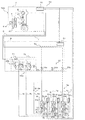
先ず、冷房運転について説明する。本実施の形態1では、第1の室内機C、第2の室内機D及び第3の室内機Eのいずれもが、冷房運転を行っている。冷房運転が行われる場合、流路切替部2は、圧縮機1から吐出された冷媒が室外熱交換器3に流入するように、切り替えられる。図2は、本発明の実施の形態1における冷房運転を示す回路図であり、図3は、本発明の実施の形態1における冷房運転のP−h線図である。
(Cooling operation)
First, the cooling operation will be described. In Embodiment 1, all of the first indoor unit C, the second indoor unit D, and the third indoor unit E are performing the cooling operation. When the cooling operation is performed, the flow path switching unit 2 is switched so that the refrigerant discharged from the compressor 1 flows into the outdoor heat exchanger 3. FIG. 2 is a circuit diagram showing the cooling operation in the first embodiment of the present invention, and FIG. 3 is a Ph diagram of the cooling operation in the first embodiment of the present invention.

図2に示すように、圧縮機1は、駆動が開始されると、低温低圧のガス冷媒を吸入して圧縮し、高温高圧のガス冷媒を吐出する。この圧縮機1の冷媒を圧縮する圧縮過程においては、圧縮機1の断熱効率の分だけ、等エントロピ線で断熱圧縮されるよりも加熱されるように圧縮される(図3の点(a)から点(b)に向かう線分)。   As shown in FIG. 2, when driving is started, the compressor 1 sucks and compresses a low-temperature and low-pressure gas refrigerant and discharges a high-temperature and high-pressure gas refrigerant. In the compression process of compressing the refrigerant of the compressor 1, the compressor 1 is compressed so as to be heated by the amount of heat insulation efficiency of the compressor 1 rather than being adiabatically compressed by an isentropic line (point (a) in FIG. 3). To the point (b).

圧縮機1から吐出された高温高圧のガス冷媒は、流路切替部2を介して室外熱交換器3に流入する。このとき、冷媒は、室外送風機3mから送風される室外空気を加熱しつつ、冷却され、中温高圧の液冷媒になる。室外熱交換器3における冷媒の状態変化は、室外熱交換器3の圧力損失を考慮すると、図3の点(b)から点(c)に向かう水平から若干傾斜した線分のようになる。   The high-temperature and high-pressure gas refrigerant discharged from the compressor 1 flows into the outdoor heat exchanger 3 via the flow path switching unit 2. At this time, the refrigerant is cooled while heating the outdoor air blown from the outdoor blower 3m, and becomes a medium-temperature high-pressure liquid refrigerant. The state change of the refrigerant in the outdoor heat exchanger 3 takes a line segment slightly inclined from the horizontal direction from the point (b) to the point (c) in FIG. 3 in consideration of the pressure loss of the outdoor heat exchanger 3.

室外熱交換器3から流出した中温高圧の液冷媒は、第1の接続配管6、第1の分岐部9bにおける第1の冷媒遮断弁21及び直列逆止弁23a、第1の室内機側接続配管6a、室内膨張部8の順序で流通する。そして、中温高圧の液冷媒は、室内膨張部8において絞られて膨張、減圧して、低温低圧の気液二相冷媒になる。なお、室内膨張部8における冷媒の状態変化は、エンタルピが一定の状態で行われる。室内膨張部8における冷媒の状態変化は、図3の点(c)から点(d)に向かう垂直線のようになる。   The medium-temperature and high-pressure liquid refrigerant that has flowed out of the outdoor heat exchanger 3 is connected to the first connection pipe 6, the first refrigerant shut-off valve 21 and the series check valve 23a in the first branch portion 9b, and the first indoor unit side connection. It distribute | circulates in order of the piping 6a and the indoor expansion part 8. FIG. The medium temperature and high pressure liquid refrigerant is squeezed and expanded and depressurized in the indoor expansion section 8 to become a low temperature and low pressure gas-liquid two-phase refrigerant. In addition, the state change of the refrigerant | coolant in the indoor expansion part 8 is performed in the state where enthalpy is constant. The state change of the refrigerant in the indoor expansion portion 8 is a vertical line from the point (c) to the point (d) in FIG.

室内膨張部8から流出した低温低圧の気液二相冷媒は、室内熱交換器5に流入する。このとき、冷媒は、室内送風機5aから送風される室内空気を冷却しつつ、加熱され、低温低圧のガス冷媒となる。室内熱交換器5における冷媒の状態変化は、室内熱交換器5の圧力損失を考慮すると、図3の点(d)から点(a)に向かう水平から若干傾斜した線分のようになる。   The low-temperature and low-pressure gas-liquid two-phase refrigerant that has flowed out of the indoor expansion section 8 flows into the indoor heat exchanger 5. At this time, the refrigerant is heated while cooling the indoor air blown from the indoor blower 5a, and becomes a low-temperature and low-pressure gas refrigerant. When the pressure loss of the indoor heat exchanger 5 is taken into consideration, the refrigerant state change in the indoor heat exchanger 5 becomes a line segment slightly inclined from the horizontal direction from the point (d) to the point (a) in FIG.

室内熱交換器5から流出した低温低圧のガス冷媒は、第2の室内機側接続配管7a、第2の冷媒遮断弁22を通って、第2の分岐部9aに至る。この第2の分岐部9aにて合流した低温低圧のガス冷媒は、第2の接続配管7及び流路切替部2を通って、圧縮機1に流入し、圧縮される。   The low-temperature and low-pressure gas refrigerant that has flowed out of the indoor heat exchanger 5 passes through the second indoor unit side connection pipe 7a and the second refrigerant shut-off valve 22, and reaches the second branch portion 9a. The low-temperature and low-pressure gas refrigerant merged at the second branch part 9a flows into the compressor 1 through the second connection pipe 7 and the flow path switching part 2, and is compressed.

(暖房運転)
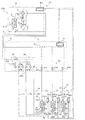
次に、暖房運転について説明する。本実施の形態1では、第1の室内機C、第2の室内機D及び第3の室内機Eのいずれもが、暖房運転を行っている。暖房運転が行われる場合、流路切替部2は、圧縮機1から吐出された冷媒が第2の分岐部9aに流入するように、切り替えられる。また、暖房運転において、冷媒は、第1の冷媒遮断弁21を通過しないため、この第1の冷媒遮断弁21は、開いていても閉じていてもよい。図4は、本発明の実施の形態1における暖房運転を示す回路図であり、図5は、本発明の実施の形態1における暖房運転のP−h線図である。
(Heating operation)
Next, the heating operation will be described. In the first embodiment, all of the first indoor unit C, the second indoor unit D, and the third indoor unit E perform the heating operation. When the heating operation is performed, the flow path switching unit 2 is switched so that the refrigerant discharged from the compressor 1 flows into the second branch unit 9a. In the heating operation, since the refrigerant does not pass through the first refrigerant cutoff valve 21, the first refrigerant cutoff valve 21 may be open or closed. 4 is a circuit diagram showing the heating operation in Embodiment 1 of the present invention, and FIG. 5 is a Ph diagram of the heating operation in Embodiment 1 of the present invention.

図4に示すように、圧縮機1は、駆動が開始されると、低温低圧のガス冷媒を吸入して圧縮し、高温高圧のガス冷媒を吐出する。この圧縮機1の冷媒を圧縮する圧縮過程においては、圧縮機1の断熱効率の分だけ、等エントロピ線で断熱圧縮されるよりも加熱されるように圧縮される(図5の点(a)から点(b)に向かう線分)。   As shown in FIG. 4, when the drive is started, the compressor 1 sucks and compresses the low-temperature and low-pressure gas refrigerant and discharges the high-temperature and high-pressure gas refrigerant. In the compression process of compressing the refrigerant of the compressor 1, the compressor 1 is compressed so as to be heated by the amount of the heat insulation efficiency of the compressor 1 rather than being adiabatically compressed by an isentropic line (point (a) in FIG. 5). To the point (b).

圧縮機1から吐出された高温高圧のガス冷媒は、流路切替部2及び第2の接続配管7を介して第2の分岐部9aに流入する。このとき、第2の分岐部9aに流入した高温高圧のガス冷媒は、第2の分岐部9aで分岐し、第2の冷媒遮断弁22、第2の室内機側接続配管7aを通って、室内熱交換器5に流入する。このとき、冷媒は、室内送風機5aから送風される室内空気を加熱しつつ、自身は冷却され、中温高圧の液冷媒になる。室内熱交換器5における冷媒の状態変化は、室内熱交換器5の圧力損失を考慮すると、図5の点(b)から点(c)に向かう水平から若干傾斜した線分のようになる。   The high-temperature and high-pressure gas refrigerant discharged from the compressor 1 flows into the second branch part 9a via the flow path switching part 2 and the second connection pipe 7. At this time, the high-temperature and high-pressure gas refrigerant that has flowed into the second branch portion 9a branches at the second branch portion 9a, passes through the second refrigerant shut-off valve 22, and the second indoor unit side connection pipe 7a, It flows into the indoor heat exchanger 5. At this time, the refrigerant is cooled while heating the indoor air blown from the indoor blower 5a, and becomes a medium-temperature high-pressure liquid refrigerant. The state change of the refrigerant in the indoor heat exchanger 5 takes a line segment slightly inclined from the horizontal direction from the point (b) to the point (c) in FIG. 5 in consideration of the pressure loss of the indoor heat exchanger 5.

室内熱交換器5から流出した中温高圧の液冷媒は、室内膨張部8に流入し、室内膨張部8において絞られて膨張、減圧して、低温低圧の気液二相冷媒になる。なお、室内膨張部8における冷媒の状態変化は、エンタルピが一定の状態で行われる。室内膨張部8における冷媒の状態変化は、図5の点(c)から点(d)に向かう垂直線のようになる。   The medium-temperature and high-pressure liquid refrigerant that has flowed out of the indoor heat exchanger 5 flows into the indoor expansion section 8, is squeezed and expanded and decompressed in the indoor expansion section 8, and becomes a low-temperature and low-pressure gas-liquid two-phase refrigerant. In addition, the state change of the refrigerant | coolant in the indoor expansion part 8 is performed in the state where enthalpy is constant. The state change of the refrigerant in the indoor expansion portion 8 is a vertical line from the point (c) to the point (d) in FIG.

室内膨張部8から流出した低温低圧の気液二相冷媒は、第1の室内機側接続配管6a、第1の分岐部9bにおける並列逆止弁23b、第1の接続配管6を通って、室外熱交換器3に流入する。このとき、冷媒は、室外送風機3mから送風される室外空気を冷却しつつ、自身は加熱され、低温低圧のガス冷媒となる。室外熱交換器3における冷媒の状態変化は、室外熱交換器3の圧力損失を考慮すると、図5の点(d)から点(a)に向かう水平から若干傾斜した線分のようになる。   The low-temperature and low-pressure gas-liquid two-phase refrigerant that has flowed out of the indoor expansion section 8 passes through the first indoor unit side connection pipe 6a, the parallel check valve 23b in the first branch section 9b, and the first connection pipe 6. It flows into the outdoor heat exchanger 3. At this time, the refrigerant is heated while cooling the outdoor air blown from the outdoor blower 3m, and becomes a low-temperature and low-pressure gas refrigerant. When the pressure loss of the outdoor heat exchanger 3 is taken into consideration, the state change of the refrigerant in the outdoor heat exchanger 3 becomes a line segment slightly inclined from the horizontal direction from the point (d) to the point (a) in FIG.

室外熱交換器3から流出した低温低圧のガス冷媒は、流路切替部2を通って、圧縮機1に流入し、圧縮される。   The low-temperature and low-pressure gas refrigerant that has flowed out of the outdoor heat exchanger 3 flows into the compressor 1 through the flow path switching unit 2 and is compressed.

(冷媒回収運転)
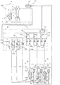
次に、冷媒が漏洩した場合において、室内への冷媒漏洩量を極力低減する冷媒回収運転について説明する。制御部70は、冷媒漏洩検出部43において第1の室内機Cから冷媒が漏洩したことが検出された場合、例えば、冷媒漏洩検出部43が、空気中の冷媒濃度を検出する冷媒濃度検出部であり、空気中の冷媒濃度が予め定められた閾値を超えた場合、室外熱交換器3が凝縮器として作用する流路となるように流路切替部2を制御する。これは、冷媒の漏洩が検出された際の運転モードが冷房運転である場合、流路はそのままであり、暖房運転である場合、流路は逆方向である。更に、制御部70は、第1の冷媒遮断弁21及び第21の冷媒遮断弁22cを閉じる。図6は、本発明の実施の形態1における冷媒回収運転を示す回路図であり、図7は、本発明の実施の形態1における冷媒回収運転のP−h線図である。
(Refrigerant recovery operation)
Next, the refrigerant recovery operation for reducing the refrigerant leakage amount to the room as much as possible when the refrigerant leaks will be described. When the refrigerant leakage detection unit 43 detects that the refrigerant has leaked from the first indoor unit C, for example, the refrigerant leakage detection unit 43 detects the refrigerant concentration in the air. When the refrigerant concentration in the air exceeds a predetermined threshold, the flow path switching unit 2 is controlled so that the outdoor heat exchanger 3 becomes a flow path that acts as a condenser. This is because when the operation mode when refrigerant leakage is detected is the cooling operation, the flow path remains as it is, and when the operation mode is the heating operation, the flow path is in the reverse direction. Furthermore, the control unit 70 closes the first refrigerant cutoff valve 21 and the twenty-first refrigerant cutoff valve 22c. FIG. 6 is a circuit diagram showing the refrigerant recovery operation in the first embodiment of the present invention, and FIG. 7 is a Ph diagram of the refrigerant recovery operation in the first embodiment of the present invention.

図6に示すように、圧縮機1は、駆動が開始されると、低温低圧のガス冷媒を吸入して圧縮し、高温高圧のガス冷媒を吐出する。この圧縮機1の冷媒を圧縮する圧縮過程においては、圧縮機1の断熱効率の分だけ、等エントロピ線で断熱圧縮されるよりも加熱されるように圧縮される(図7の点(a)から点(b)に向かう線分)。   As shown in FIG. 6, when the drive is started, the compressor 1 sucks and compresses the low-temperature and low-pressure gas refrigerant and discharges the high-temperature and high-pressure gas refrigerant. In the compression process of compressing the refrigerant of the compressor 1, the compressor 1 is compressed so as to be heated by the amount of heat insulation efficiency of the compressor 1 rather than being adiabatically compressed by an isentropic line (point (a) in FIG. 7). To the point (b).

圧縮機1から吐出された高温高圧のガス冷媒は、流路切替部2を介して室外熱交換器3に流入する。このとき、冷媒は、室外送風機3mから送風される室外空気を加熱しつつ、自身は冷却され、中温高圧の液冷媒になる。室外熱交換器3における冷媒の状態変化は、室外熱交換器3の圧力損失を考慮すると、図7の点(b)から点(c)に向かう水平から若干傾斜した線分のようになる。   The high-temperature and high-pressure gas refrigerant discharged from the compressor 1 flows into the outdoor heat exchanger 3 via the flow path switching unit 2. At this time, while the refrigerant heats outdoor air blown from the outdoor blower 3m, it is cooled and becomes a medium-temperature high-pressure liquid refrigerant. The state change of the refrigerant in the outdoor heat exchanger 3 takes a line segment slightly inclined from the horizontal direction from the point (b) to the point (c) in FIG. 7 in consideration of the pressure loss of the outdoor heat exchanger 3.

室外熱交換器3から流出した中温高圧の液冷媒は、第1の接続配管6を流通した後、第1の分岐部9bにおける第1の冷媒遮断弁21によって、堰き止められる。これにより、液冷媒は、第1の接続配管6の内部に貯留される。このように、室外熱交換器3が凝縮器として作用することによって、室外熱交換器3から流出する冷媒は液冷媒になり、この液冷媒は、ガス冷媒よりも、配管内部に留まり易い。従って、冷凍サイクル内を流通する冷媒が、可能な限り回収される。また、第21の冷媒遮断弁22cは閉じているため、第2の室内機D及び第3の室内機E等に流通している冷媒が、第1の室内機Cに流入せず、冷媒の漏洩が阻止される。なお、第2の室内熱交換器5d及び第3の室内熱交換器5eにおける冷媒の圧力は、第22の冷媒遮断弁22d及び第23の冷媒遮断弁22eが開いているため、圧縮機1の吸入側の圧力と同等である(図7の点(d))。また、第1の室内機Cにおける冷媒の圧力は、冷媒が室内に漏洩しているため、いずれは、大気圧PAまで低下する(図7の点(e))。   The medium-temperature and high-pressure liquid refrigerant that has flowed out of the outdoor heat exchanger 3 flows through the first connection pipe 6 and is then blocked by the first refrigerant shut-off valve 21 in the first branch portion 9b. As a result, the liquid refrigerant is stored in the first connection pipe 6. Thus, when the outdoor heat exchanger 3 acts as a condenser, the refrigerant flowing out of the outdoor heat exchanger 3 becomes a liquid refrigerant, and this liquid refrigerant is more likely to stay inside the pipe than a gas refrigerant. Therefore, the refrigerant flowing through the refrigeration cycle is recovered as much as possible. Further, since the 21st refrigerant shutoff valve 22c is closed, the refrigerant circulating in the second indoor unit D, the third indoor unit E, etc. does not flow into the first indoor unit C, Leakage is prevented. Note that the refrigerant pressure in the second indoor heat exchanger 5d and the third indoor heat exchanger 5e is the same as that of the compressor 1 because the 22nd refrigerant shutoff valve 22d and the 23rd refrigerant shutoff valve 22e are open. This is equivalent to the pressure on the suction side (point (d) in FIG. 7). Further, the refrigerant pressure in the first indoor unit C eventually decreases to the atmospheric pressure PA because the refrigerant leaks into the room (point (e) in FIG. 7).

また、第1の室内機C、第2の室内機D及び第3の室内機Eのいずれかにおいて、冷媒が漏洩した場合、中継機Bの中継制御部51は、冷媒が漏洩した室内機Xに接続された第2の冷媒遮断弁22及び第1の冷媒遮断弁21の開閉動作を行う。第2の冷媒遮断弁22は、通常運転時には開いており、冷媒が漏洩した際に閉じる。これにより、冷媒が第2の室内機側接続配管7aに流入することが防止される。また、第1の冷媒遮断弁21は、通常運転時には開いており、冷媒が漏洩した際に閉じる。これにより、冷媒が漏洩した室内機X、第1の室内機側接続配管6a及び第2の室内機側接続配管7aの圧力が、第1の接続配管6の圧力よりも高い場合、並列逆止弁23bを通って、冷媒が漏洩した室内機X、第1の室内機側接続配管6a及び第2の室内機側接続配管7aに貯留する冷媒が、第1の接続配管6の内部に回収される。一方、冷媒が漏洩した室内機X、第1の室内機側接続配管6a及び第2の室内機側接続配管7aの圧力が、第1の接続配管6の圧力よりも低い場合、冷媒が漏洩した室内機X、第1の室内機側接続配管6a及び第2の室内機側接続配管7aに冷媒が流出することが防止される。   Further, when the refrigerant leaks in any of the first indoor unit C, the second indoor unit D, and the third indoor unit E, the relay control unit 51 of the relay unit B causes the indoor unit X in which the refrigerant has leaked. The second refrigerant cutoff valve 22 and the first refrigerant cutoff valve 21 connected to are opened and closed. The second refrigerant shut-off valve 22 is open during normal operation and closed when the refrigerant leaks. This prevents the refrigerant from flowing into the second indoor unit side connection pipe 7a. The first refrigerant shut-off valve 21 is open during normal operation and is closed when the refrigerant leaks. Thereby, when the pressure of the indoor unit X, the first indoor unit side connection pipe 6a, and the second indoor unit side connection pipe 7a in which the refrigerant has leaked is higher than the pressure of the first connection pipe 6, parallel check Through the valve 23b, the refrigerant stored in the indoor unit X, the first indoor unit side connection pipe 6a, and the second indoor unit side connection pipe 7a in which the refrigerant has leaked is recovered in the first connection pipe 6. The On the other hand, when the pressure of the indoor unit X, the first indoor unit side connection pipe 6a, and the second indoor unit side connection pipe 7a where the refrigerant leaked is lower than the pressure of the first connection pipe 6, the refrigerant leaked The refrigerant is prevented from flowing out to the indoor unit X, the first indoor unit side connecting pipe 6a, and the second indoor unit side connecting pipe 7a.

ここで、直列逆止弁23a(第1の直列逆止弁23c,第2の直列逆止弁23d,第3の直列逆止弁23e)は、室内機X間における冷媒の流通を防ぐものである。いずれかの室内機Xで冷媒が漏洩し、第1の冷媒遮断弁21が遮断された場合、直列逆止弁23aによって、冷媒が漏洩していない他の室内機X側の冷媒が、冷媒が漏洩した室内機X側に流通することを防ぐことができる。   Here, the series check valve 23a (the first series check valve 23c, the second series check valve 23d, and the third series check valve 23e) prevents the refrigerant from flowing between the indoor units X. is there. When the refrigerant leaks in any of the indoor units X and the first refrigerant shut-off valve 21 is shut off, the refrigerant on the other indoor unit X side where the refrigerant is not leaking is changed by the series check valve 23a. Distribution to the leaked indoor unit X side can be prevented.

以上説明したように、本実施の形態1に係る空気調和装置100は、第1の分岐部9bにおいて、第1の冷媒遮断弁21が、室内機Xの台数未満の台数だけ備わっているため、コスト低減及び制御簡略化を両立することができる。また、第1の冷媒遮断弁21が、室内機Xの第1の室内機側接続配管6aが合流する第1の分岐部9bに設けられ、室内機Xの第2の室内機側接続配管7a毎に設けられている。このため、いずれかの室内機Xにおいて、室内への冷媒の漏洩が発生した場合、漏洩している室内機Xの第2の室内機側接続配管7aに設けられた第2の冷媒遮断弁22、及び第1の分岐部9bにおける第1の室内機側接続配管6aが合流した部分に設けられた第1の冷媒遮断弁21を閉止することによって、室内への冷媒の漏洩を、極力減らすことができる。   As described above, the air-conditioning apparatus 100 according to Embodiment 1 includes the first refrigerant shut-off valves 21 in the first branch portion 9b, which is less than the number of indoor units X. Both cost reduction and control simplification can be achieved. The first refrigerant shut-off valve 21 is provided in the first branch portion 9b where the first indoor unit side connection pipe 6a of the indoor unit X joins, and the second indoor unit side connection pipe 7a of the indoor unit X is provided. It is provided for each. For this reason, in the case where any refrigerant leaks indoors in any of the indoor units X, the second refrigerant shut-off valve 22 provided in the second indoor unit side connection pipe 7a of the leaking indoor unit X. , And closing the first refrigerant shut-off valve 21 provided at the portion where the first indoor unit side connecting pipe 6a joins in the first branch portion 9b, to reduce the leakage of the refrigerant to the room as much as possible. Can do.

また、制御部70は、冷媒漏洩検出部43が複数の室内機Xの少なくとも1台において冷媒が漏洩したことを検出した場合、室外熱交換器3が凝縮器として作用する流路となるように流路切替部2を制御している。このため、室外熱交換器3から流出する冷媒は液冷媒になり、この液冷媒は、ガス冷媒よりも、配管内部に留まり易い。従って、冷凍サイクル内を流通する冷媒の回収量を増大させることができる。   Moreover, when the refrigerant | coolant leak detection part 43 detects that the refrigerant | coolant leaked in at least 1 of the some indoor unit X, the control part 70 becomes the flow path where the outdoor heat exchanger 3 acts as a condenser. The flow path switching unit 2 is controlled. For this reason, the refrigerant flowing out of the outdoor heat exchanger 3 becomes a liquid refrigerant, and this liquid refrigerant is more likely to stay inside the pipe than the gas refrigerant. Accordingly, it is possible to increase the recovery amount of the refrigerant flowing through the refrigeration cycle.

実施の形態2.
次に、本実施の形態2に係る空気調和装置101aについて説明する。図8Aは、本発明の実施の形態2に係る空気調和装置101aを示す回路図である。本実施の形態2は、中継機Bにおいて、第2の冷媒遮断弁22の設置台数が室内機Xの台数未満である点で、実施の形態1と相違する。本実施の形態2では、実施の形態1と共通する部分は同一の符号を付して説明を省略し、実施の形態1との相違点を中心に説明する。
Embodiment 2. FIG.
Next, the air conditioning apparatus 101a according to the second embodiment will be described. FIG. 8A is a circuit diagram showing an air-conditioning apparatus 101a according to Embodiment 2 of the present invention. The second embodiment is different from the first embodiment in that the number of installed second refrigerant cutoff valves 22 is less than the number of indoor units X in the relay unit B. In the second embodiment, portions common to the first embodiment are denoted by the same reference numerals, description thereof is omitted, and differences from the first embodiment will be mainly described.

図8Aに示すように、中継機Bは、室内中継逆止弁24a及び中継室内逆止弁24bを備えている。室内中継逆止弁24aは、複数の室内機Xにおける各第2の室内機側接続配管7a、即ち冷房運転における各ガス側配管が合流する第2の分岐部9aにおいて、室内機Xから中継機Bに向かう冷媒の流れを許容するものである。中継室内逆止弁24bは、室内中継逆止弁24aに対し並列に接続されるものであり、暖房運転における各ガス側配管に分岐する第2の分岐部9aにおいて、中継機Bから室内機Xに向かう冷媒の流れを許容するものである。第2の冷媒遮断弁22は、中継室内逆止弁24bに分岐する配管の上流側に設けられる。即ち、第2の分岐部9aは、室内機Xから中継機Bへの冷媒の流通を許容する経路、及び、中継機Bから室内機Xへの冷媒の流通を許容する経路で構成されており、第2の冷媒遮断弁22は、中継機Bから室内機Xへの冷媒の流通を許容する経路において、複数の室内機Xに分岐する分岐点の上流側に設けられている。   As shown in FIG. 8A, the relay unit B includes an indoor relay check valve 24a and a relay indoor check valve 24b. The indoor relay check valve 24a is connected from the indoor unit X to the second branch unit 9a where each second indoor unit side connection pipe 7a in the plurality of indoor units X, that is, each gas side pipe in the cooling operation joins. The refrigerant flow toward B is allowed. The relay indoor check valve 24b is connected in parallel to the indoor relay check valve 24a, and in the second branch portion 9a branched to each gas side pipe in the heating operation, the relay unit B is connected to the indoor unit X. The flow of the refrigerant toward is allowed. The second refrigerant shut-off valve 22 is provided on the upstream side of the pipe branched to the relay chamber check valve 24b. That is, the second branching portion 9a is configured by a path that allows the refrigerant to flow from the indoor unit X to the relay unit B, and a path that allows the refrigerant to flow from the relay unit B to the indoor unit X. The second refrigerant shut-off valve 22 is provided on the upstream side of a branch point that branches into the plurality of indoor units X in a path that allows the refrigerant to flow from the relay unit B to the indoor unit X.

ここで、室内中継逆止弁24aは総称であり、第21の室内機側接続配管7cに設けられた第1の室内中継逆止弁24cと、第22の室内機側接続配管7dに設けられた第2の室内中継逆止弁24dと、第23の室内機側接続配管7eに設けられた第3の室内中継逆止弁24eとからなる。一方、中継室内逆止弁24bは総称であり、第21の室内機側接続配管7cに設けられた第1の中継室内逆止弁24fと、第22の室内機側接続配管7dに設けられた第2の中継室内逆止弁24gと、第23の室内機側接続配管7eに設けられた第3の中継室内逆止弁24hとからなる。   Here, the indoor relay check valve 24a is a generic name, and is provided in the first indoor relay check valve 24c provided in the 21st indoor unit side connection pipe 7c and the 22nd indoor unit side connection pipe 7d. The second indoor relay check valve 24d and the third indoor relay check valve 24e provided in the 23rd indoor unit side connection pipe 7e. On the other hand, the relay indoor check valve 24b is a generic term, and is provided in the first relay indoor check valve 24f provided in the 21st indoor unit side connection pipe 7c and the 22nd indoor unit side connection pipe 7d. It consists of a second relay indoor check valve 24g and a third relay indoor check valve 24h provided in the 23rd indoor unit side connection pipe 7e.

ここで、中継室内逆止弁24b(第1の中継室内逆止弁24f,第2の中継室内逆止弁24g,第3の中継室内逆止弁24h)は、室内機X間における冷媒の流通を防ぐものである。いずれかの室内機Xで冷媒が漏洩し、第2の冷媒遮断弁22が遮断された場合、中継室内逆止弁24bによって、冷媒が漏洩していない他の室内機X側の冷媒が、冷媒が漏洩した室内機X側に流通することを防ぐことができる。   Here, the relay chamber check valve 24b (the first relay chamber check valve 24f, the second relay chamber check valve 24g, and the third relay chamber check valve 24h) distributes the refrigerant between the indoor units X. Is to prevent. When the refrigerant leaks in any of the indoor units X and the second refrigerant shut-off valve 22 is shut off, the refrigerant in the other indoor unit X side where the refrigerant is not leaked by the relay indoor check valve 24b becomes the refrigerant. Can be prevented from circulating to the leaked indoor unit X side.

制御部70は、冷媒漏洩検出部43が、複数の室内機Xの少なくとも1台において冷媒が漏洩したことを検出した場合、第1の冷媒遮断弁21及び第2の冷媒遮断弁22を閉じる機能を備えている。   The control unit 70 has a function of closing the first refrigerant cutoff valve 21 and the second refrigerant cutoff valve 22 when the refrigerant leakage detection unit 43 detects that the refrigerant has leaked in at least one of the plurality of indoor units X. It has.

以上説明したように、本実施の形態2に係る空気調和装置101aは、第2の分岐部9aにおいて、第2の冷媒遮断弁22が、室内機Xの台数未満の台数だけ備わっている。このため、コスト低減及び制御簡略化を両立することができる。また、第1の冷媒遮断弁21が、室内機Xの第1の室内機側接続配管6aが合流する第1の分岐部9bに設けられ、第2の冷媒遮断弁22が、室内機Xの第2の室内機側接続配管7aが合流する第2の分岐部9aに設けられている。このため、いずれかの室内機Xにおいて、室内への冷媒の漏洩が発生した場合、第2の分岐部9aにおける第2の室内機側接続配管7aが合流した部分に設けられた第2の冷媒遮断弁22、及び第1の分岐部9bにおける第1の室内機側接続配管6aが合流した部分に設けられた第1の冷媒遮断弁21を閉止することによって、室内への冷媒の漏洩を、極力減らすことができる。   As described above, the air-conditioning apparatus 101a according to the second embodiment includes the second refrigerant shut-off valves 22 in the second branch portion 9a, which is less than the number of indoor units X. For this reason, cost reduction and control simplification can be compatible. Moreover, the 1st refrigerant | coolant cutoff valve 21 is provided in the 1st branch part 9b where the 1st indoor unit side connection piping 6a of the indoor unit X merges, and the 2nd refrigerant | coolant cutoff valve 22 is the indoor unit X of The second indoor unit side connection pipe 7a is provided at the second branch portion 9a where the second indoor unit side connection pipe 7a joins. For this reason, in any one of the indoor units X, when the refrigerant leaks into the room, the second refrigerant provided in the portion where the second indoor unit side connection pipe 7a merges in the second branch portion 9a. By closing the first refrigerant shut-off valve 21 provided at the portion where the shut-off valve 22 and the first indoor unit side connecting pipe 6a in the first branch portion 9b merge, leakage of the refrigerant into the room, It can be reduced as much as possible.

また、制御部70は、冷媒漏洩検出部43が複数の室内機Xの少なくとも1台において冷媒が漏洩したことを検出した場合、室外熱交換器3が凝縮器として作用する流路となるように流路切替部2を制御している。このため、室外熱交換器3から流出する冷媒は液冷媒になり、この液冷媒は、ガス冷媒よりも、配管内部に留まり易い。従って、冷凍サイクル内を流通する冷媒の回収量を増大させることができる。   Moreover, when the refrigerant | coolant leak detection part 43 detects that the refrigerant | coolant leaked in at least 1 of the some indoor unit X, the control part 70 becomes the flow path where the outdoor heat exchanger 3 acts as a condenser. The flow path switching unit 2 is controlled. For this reason, the refrigerant flowing out of the outdoor heat exchanger 3 becomes a liquid refrigerant, and this liquid refrigerant is more likely to stay inside the pipe than the gas refrigerant. Accordingly, it is possible to increase the recovery amount of the refrigerant flowing through the refrigeration cycle.

(実施の形態2の変形例)
次に、本実施の形態2の変形例に係る空気調和装置101について説明する。図8Bは、本発明の実施の形態2の変形例に係る空気調和装置101を示す回路図である。実施の形態2の変形例は、中継機Bが、室内中継流路制御弁10a及び中継室内流路制御弁10bを備えており、第2の冷媒遮断弁22を備えていない点で、実施の形態1,2と相違する。本実施の形態2の変形例では、実施の形態1,2と共通する部分は同一の符号を付して説明を省略し、実施の形態1,2との相違点を中心に説明する。
(Modification of Embodiment 2)
Next, an air conditioner 101 according to a modification of the second embodiment will be described. FIG. 8B is a circuit diagram showing an air conditioner 101 according to a modification of the second embodiment of the present invention. The modification of the second embodiment is implemented in that the relay machine B includes the indoor relay flow path control valve 10a and the relay indoor flow path control valve 10b, and does not include the second refrigerant cutoff valve 22. Different from Embodiments 1 and 2. In the modification of the second embodiment, portions common to the first and second embodiments are denoted by the same reference numerals and description thereof will be omitted, and differences from the first and second embodiments will be mainly described.

図8Bに示すように、中継機Bは、室内中継流路制御弁10a、中継室内流路制御弁10b、室内中継逆止弁24a及び中継室内逆止弁24bを備えている。室内中継流路制御弁10aは、複数の室内機Xにおける各第2の室内機側接続配管7a、即ち冷房運転における各ガス側配管が合流する第2の分岐部9aにおいて、室内機Xから中継機Bに向かう片方向における冷媒の流通を制御するものである。また、中継室内流路制御弁10bは、第2の分岐部9aにおいて、中継機Bから室内機Xに向かう片方向における冷媒の流通を制御し、室内中継流路制御弁10aに対し並列に接続されるものである。これらの室内中継流路制御弁10a及び中継室内流路制御弁10bは、例えば電磁弁である。そして、室内中継流路制御弁10aは、室内機Xの側(図8Bにおける矢印の基端の側)よりも、第2の分岐部9aの側(図8Bにおける矢印の先端の側)の方が冷媒の圧力が高い場合に、正常に開閉動作が行われる。また、中継室内流路制御弁10bは、室内機Xの側(図8Bにおける矢印の先端の側)よりも、第2の分岐部9aの側(図8Bにおける矢印の基端の側)の方が冷媒の圧力が高い場合に、正常に開閉動作が行われる。   As shown in FIG. 8B, the relay unit B includes an indoor relay flow path control valve 10a, a relay indoor flow path control valve 10b, an indoor relay check valve 24a, and a relay indoor check valve 24b. The indoor relay flow path control valve 10a relays from the indoor unit X at each second indoor unit side connection pipe 7a in the plurality of indoor units X, that is, in the second branch portion 9a where the gas side pipes in the cooling operation join. The flow of the refrigerant in one direction toward the machine B is controlled. The relay indoor flow path control valve 10b controls the refrigerant flow in one direction from the relay machine B to the indoor unit X at the second branching portion 9a, and is connected in parallel to the indoor relay flow path control valve 10a. It is what is done. The indoor relay flow path control valve 10a and the relay indoor flow path control valve 10b are, for example, electromagnetic valves. The indoor relay flow path control valve 10a is closer to the second branch portion 9a side (the tip end side of the arrow in FIG. 8B) than to the indoor unit X side (the base end side of the arrow in FIG. 8B). When the refrigerant pressure is high, the opening / closing operation is normally performed. Further, the relay indoor flow path control valve 10b is closer to the second branch portion 9a side (the base end side of the arrow in FIG. 8B) than to the indoor unit X side (the tip end side of the arrow in FIG. 8B). When the refrigerant pressure is high, the opening / closing operation is normally performed.

図8Cは、本発明の実施の形態2の変形例における室内中継流路制御弁10aの構造を示す図である。ここで、室内中継流路制御弁10aの構造について説明する。図8Cに示すように、室内中継流路制御弁10aは、例えばパイロット式の電磁弁である。室内中継流路制御弁10a(パイロット式の電磁弁)は、比較的Cv値が大きな弁であり、プランジャ80と主弁81とによって流路が塞がれている。プランジャ80と主弁81とは独立しており、図8cでは、低圧雰囲気の冷媒がプランジャ80に封入されている。そして、プランジャ80はソレノイドコイル82の吸引力によって作動し、また、主弁81は流体圧力によって作動する。これにより、簡易な構造且つ小容量の電力で、大口径の主弁81を動作させることができる。このように、本実施の形態2の変形例では、片方向の流通を遮断する弁が用いられているため、双方向の流通を遮断する弁が用いられるよりもコストを削減することができる。   FIG. 8C is a diagram showing the structure of the indoor relay flow path control valve 10a in a modification of the second embodiment of the present invention. Here, the structure of the indoor relay flow path control valve 10a will be described. As shown in FIG. 8C, the indoor relay flow path control valve 10a is, for example, a pilot-type electromagnetic valve. The indoor relay flow path control valve 10a (pilot solenoid valve) is a valve having a relatively large Cv value, and the flow path is blocked by the plunger 80 and the main valve 81. The plunger 80 and the main valve 81 are independent of each other. In FIG. 8 c, a low-pressure atmosphere refrigerant is sealed in the plunger 80. The plunger 80 is operated by the suction force of the solenoid coil 82, and the main valve 81 is operated by the fluid pressure. As a result, the large-diameter main valve 81 can be operated with a simple structure and a small amount of power. As described above, in the modification of the second embodiment, since the valve that blocks the unidirectional flow is used, the cost can be reduced as compared with the case where the valve that blocks the bidirectional flow is used.

なお、中継室内流路制御弁10bも、室内中継流路制御弁10aと同様の構造を有していてもよい。   The relay indoor flow path control valve 10b may have the same structure as the indoor relay flow path control valve 10a.

なお、室内中継流路制御弁10aは総称であり、第21の室内機側接続配管7cに設けられた第1の室内中継流路制御弁10cと、第22の室内機側接続配管7dに設けられた第2の室内中継流路制御弁10dと、第23の室内機側接続配管7eに設けられた第3の室内中継流路制御弁10eとからなる。また、中継室内流路制御弁10bは総称であり、第21の室内機側接続配管7cに設けられた第1の中継室内流路制御弁10fと、第22の室内機側接続配管7dに設けられた第2の中継室内流路制御弁10gと、第23の室内機側接続配管7eに設けられた第3の中継室内流路制御弁10hとからなる。   The indoor relay flow path control valve 10a is a generic term, and is provided in the first indoor relay flow path control valve 10c provided in the 21st indoor unit side connection pipe 7c and the 22nd indoor unit side connection pipe 7d. The second indoor relay flow path control valve 10d and the third indoor relay flow path control valve 10e provided in the 23rd indoor unit side connection pipe 7e. The relay indoor flow path control valve 10b is a generic term, and is provided in the first relay indoor flow path control valve 10f provided in the 21st indoor unit side connection pipe 7c and the 22nd indoor unit side connection pipe 7d. The second relay indoor flow path control valve 10g and the third relay indoor flow path control valve 10h provided in the 23rd indoor unit side connection pipe 7e.

また、室内中継逆止弁24aは、室内中継流路制御弁10aに対し直列に接続されるものであり、室内中継流路制御弁10aの上流側に設けられている。なお、室内中継逆止弁24aは、室内中継流路制御弁10aの下流側に設けられてもよい。更に、中継室内逆止弁24bは、中継室内流路制御弁10bに対し直列に接続されるものであり、中継室内流路制御弁10bの上流側に設けられている。なお、中継室内逆止弁24bは、中継室内流路制御弁10bの下流側に設けられてもよい。このように、室内中継逆止弁24aが室内中継流路制御弁10aに対し直列に接続され、また、中継室内逆止弁24bが中継室内流路制御弁10bに対し直列に接続されることによって、冷凍サイクルにおける冷媒の流通方向が変動しても、室内中継流路制御弁10a及び中継室内流路制御弁10bは、正常に開閉動作が行われる。なお、室内中継流路制御弁10aは省略することも可能であり、室内中継逆止弁24aのみ設置していてもよい。   The indoor relay check valve 24a is connected in series to the indoor relay flow path control valve 10a, and is provided upstream of the indoor relay flow path control valve 10a. The indoor relay check valve 24a may be provided on the downstream side of the indoor relay flow path control valve 10a. Further, the relay chamber check valve 24b is connected in series to the relay chamber flow control valve 10b, and is provided on the upstream side of the relay chamber flow control valve 10b. The relay chamber check valve 24b may be provided on the downstream side of the relay chamber flow control valve 10b. Thus, the indoor relay check valve 24a is connected in series to the indoor relay flow path control valve 10a, and the relay indoor check valve 24b is connected in series to the relay indoor flow path control valve 10b. Even if the flow direction of the refrigerant in the refrigeration cycle varies, the indoor relay flow path control valve 10a and the relay indoor flow path control valve 10b are normally opened and closed. The indoor relay flow path control valve 10a can be omitted, and only the indoor relay check valve 24a may be provided.

室内中継逆止弁24aは総称であり、第21の室内機側接続配管7cに設けられた第1の室内中継逆止弁24cと、第22の室内機側接続配管7dに設けられた第2の室内中継逆止弁24dと、第23の室内機側接続配管7eに設けられた第3の室内中継逆止弁24eとからなる。中継室内逆止弁24bは総称であり、第21の室内機側接続配管7cに設けられた第1の中継室内逆止弁24fと、第22の室内機側接続配管7dに設けられた第2の中継室内逆止弁24gと、第23の室内機側接続配管7eに設けられた第3の中継室内逆止弁24hとからなる。   The indoor relay check valve 24a is a generic name, and the first indoor relay check valve 24c provided in the 21st indoor unit side connection pipe 7c and the second indoor relay check valve 24d provided in the 22nd indoor unit side connection pipe 7d. Indoor relay check valve 24d, and a third indoor relay check valve 24e provided in the 23rd indoor unit side connection pipe 7e. The relay indoor check valve 24b is a generic name, and the first relay indoor check valve 24f provided in the 21st indoor unit side connection pipe 7c and the second provided in the 22nd indoor unit side connection pipe 7d. Relay indoor check valve 24g and a third relay indoor check valve 24h provided in the 23rd indoor unit side connection pipe 7e.

制御部70は、冷媒漏洩検出部43が、複数の室内機Xの少なくとも1台において冷媒が漏洩したことを検出した場合、冷媒が漏洩している室内機Xに接続された室内中継流路制御弁10aを開き、冷媒が漏洩している室内機Xに接続された中継室内流路制御弁10bを閉じ、第1の冷媒遮断弁21を閉じる機能を備えている。   When the refrigerant leakage detection unit 43 detects that the refrigerant has leaked in at least one of the plurality of indoor units X, the control unit 70 controls the indoor relay flow path connected to the indoor unit X in which the refrigerant is leaking. The valve 10a is opened, the relay indoor flow path control valve 10b connected to the indoor unit X where the refrigerant is leaking is closed, and the first refrigerant shut-off valve 21 is closed.

室内機Xにおいて冷房運転が行われる場合、室内中継流路制御弁10aが開き、中継室内流路制御弁10bが閉じる。また、室内機Xにおいて暖房運転が行われる場合、中継室内流路制御弁10bが開き、室内中継流路制御弁10aが閉じる。   When the cooling operation is performed in the indoor unit X, the indoor relay flow path control valve 10a is opened and the relay indoor flow path control valve 10b is closed. Moreover, when heating operation is performed in the indoor unit X, the relay indoor flow path control valve 10b is opened, and the indoor relay flow path control valve 10a is closed.

制御部70は、冷媒漏洩検出部43が複数の室内機Xの少なくとも1台において冷媒が漏洩したことを検出した場合、室外熱交換器3が凝縮器として作用する流路となるように流路切替部2を制御する。そして、制御部70は、冷媒が漏洩している室内機Xに接続された室内中継流路制御弁10aを開き、冷媒が漏洩している室内機Xに接続された中継室内流路制御弁10bを閉じ、第1の冷媒遮断弁21を閉じる。   When the refrigerant leakage detection unit 43 detects that the refrigerant has leaked in at least one of the plurality of indoor units X, the control unit 70 sets the flow path so that the outdoor heat exchanger 3 functions as a flow path. The switching unit 2 is controlled. And the control part 70 opens the indoor relay flow path control valve 10a connected to the indoor unit X in which the refrigerant is leaking, and the relay indoor flow path control valve 10b connected to the indoor unit X in which the refrigerant is leaking. And the first refrigerant shutoff valve 21 is closed.

次に、本実施の形態2の変形例に係る空気調和装置101の作用について説明する。冷媒が漏洩している室内機Xに接続された中継室内流路制御弁10bは閉じているため、冷媒が漏洩したことにより圧力が大気圧に近づくように低下している室内機Xには、冷媒が流通しない。また、本実施の形態2の変形例では、冷媒漏洩検出部43によって、冷媒が漏洩したことが検出されると、制御部70が、室外熱交換器3が凝縮器として作用する流路となるように流路切替部2を制御する。これと共に、制御部70は、圧縮機1が増速して、圧縮機1の吸入圧力が低下する(図7の点(a))。このように、空気調和装置101は、圧縮機1の吸入圧力を、冷媒の漏洩が発生した室内機Xの圧力よりも低下させることによって、室内中継逆止弁24aを通って、冷媒の漏洩が発生した室内機Xを含めた全ての室内機Xから冷媒を回収し易くなる。従って、室内に漏洩する冷媒の漏洩量を極力低減することができる。   Next, the effect | action of the air conditioning apparatus 101 which concerns on the modification of this Embodiment 2 is demonstrated. Since the relay indoor flow path control valve 10b connected to the indoor unit X in which the refrigerant is leaking is closed, the indoor unit X in which the pressure drops to approach atmospheric pressure due to the leakage of the refrigerant is The refrigerant does not circulate. In the modification of the second embodiment, when the refrigerant leakage detection unit 43 detects that the refrigerant has leaked, the control unit 70 becomes a flow path in which the outdoor heat exchanger 3 acts as a condenser. Thus, the flow path switching unit 2 is controlled. At the same time, the controller 70 increases the speed of the compressor 1 and decreases the suction pressure of the compressor 1 (point (a) in FIG. 7). As described above, the air conditioner 101 reduces the suction pressure of the compressor 1 below the pressure of the indoor unit X where the refrigerant has leaked, so that the refrigerant leaks through the indoor relay check valve 24a. It becomes easy to collect the refrigerant from all the indoor units X including the generated indoor unit X. Therefore, the leakage amount of the refrigerant leaking into the room can be reduced as much as possible.

実施の形態3.
次に、本実施の形態3に係る空気調和装置102について説明する。図9は、本発明の実施の形態3に係る空気調和装置102を示す回路図である。実施の形態3は、第2の分岐部9aが、圧縮機1の吐出側に接続される第3の分岐部9cと、圧縮機1の吸入側に接続される第4の分岐部9dとを備えている点で、実施の形態2と相違する。本実施の形態3では、実施の形態1、2と共通する部分は同一の符号を付して説明を省略し、実施の形態1、2との相違点を中心に説明する。
Embodiment 3 FIG.
Next, the air conditioning apparatus 102 according to Embodiment 3 will be described. FIG. 9 is a circuit diagram showing an air-conditioning apparatus 102 according to Embodiment 3 of the present invention. In the third embodiment, the second branch portion 9a includes a third branch portion 9c connected to the discharge side of the compressor 1 and a fourth branch portion 9d connected to the suction side of the compressor 1. This is different from the second embodiment. In the third embodiment, portions common to the first and second embodiments are denoted by the same reference numerals and the description thereof is omitted, and the difference from the first and second embodiments will be mainly described.

図9に示すように、圧縮機1の吐出側には、第3の接続配管11の一端が接続されており、この第3の接続配管11の他端には、第2の分岐部9aにおける第3の分岐部9cが接続されている。この第3の分岐部9cから、冷媒が中継室内流路制御弁10bに分岐する。なお、第3の分岐部9cは、第3の接続配管11を介して、圧縮機1の吐出側に接続されているため、冷媒の流通方向は一定である。このため、実施の形態2における中継室内逆止弁24bは省かれている。   As shown in FIG. 9, one end of the third connection pipe 11 is connected to the discharge side of the compressor 1, and the other end of the third connection pipe 11 is connected to the second branch portion 9 a. A third branch 9c is connected. From the third branch portion 9c, the refrigerant branches to the relay chamber flow control valve 10b. In addition, since the 3rd branch part 9c is connected to the discharge side of the compressor 1 via the 3rd connection piping 11, the distribution direction of a refrigerant | coolant is constant. For this reason, the relay chamber check valve 24b in the second embodiment is omitted.

そして、第2の接続配管7には、第2の分岐部9aにおける第4の分岐部9dが接続されている。この第4の分岐部9dは、室内中継流路制御弁10aから冷媒が合流するものである。また、室外機Aは、室外膨張部20を備えており、第1の接続配管6における室外熱交換器3の側に設けられている。   And the 4th branch part 9d in the 2nd branch part 9a is connected to the 2nd connection piping 7. FIG. The fourth branch portion 9d is where the refrigerant merges from the indoor relay flow path control valve 10a. The outdoor unit A includes an outdoor expansion unit 20 and is provided on the outdoor heat exchanger 3 side in the first connection pipe 6.

中継機Bに設けられた室内中継流路制御弁10a及び中継室内流路制御弁10bの開閉によって、室内機Xが、圧縮機1の吐出側に接続されるか、圧縮機1の吸入側に接続されるかが切り替えられる。これにより、室内機Xは、冷房運転又は暖房運転を行う。そして、冷媒の漏洩がない状態で圧縮機1が動作した場合、各分岐部における圧力は、第3の分岐部9cの圧力>第1の分岐部9bの圧力>第4の分岐部9dの圧力となるため、室内中継流路制御弁10a及び中継室内流路制御弁10bは正常に動作する。なお、室内中継流路制御弁10aは、実施の形態2と同様に、室内中継逆止弁24aが直列に接続されているため、室内機Xにおいて冷媒の漏洩が発生し、室内機Xの側の圧力が低下しても、冷媒の漏洩が発生した室内機X以外に流通する冷媒は、冷媒の漏洩が発生した室内機Xに流入しない。   By opening / closing the indoor relay flow path control valve 10a and the relay indoor flow path control valve 10b provided in the relay machine B, the indoor unit X is connected to the discharge side of the compressor 1 or to the suction side of the compressor 1 The connection is switched. Thereby, the indoor unit X performs a cooling operation or a heating operation. When the compressor 1 operates in a state where there is no refrigerant leakage, the pressure in each branch portion is the pressure of the third branch portion 9c> the pressure of the first branch portion 9b> the pressure of the fourth branch portion 9d. Therefore, the indoor relay flow path control valve 10a and the relay indoor flow path control valve 10b operate normally. In the indoor relay flow path control valve 10a, similarly to the second embodiment, the indoor relay check valve 24a is connected in series, so that the refrigerant leaks in the indoor unit X, and the indoor unit X side Even if the pressure of the refrigerant decreases, the refrigerant circulating other than the indoor unit X where the refrigerant leaks does not flow into the indoor unit X where the refrigerant leaks.

次に、本実施の形態3に係る空気調和装置102の動作について説明する。本実施の形態3に係る空気調和装置102は、室内機X毎に冷房又は暖房を選択し、冷房が行われる室内機Xと暖房運転が行われる室内機Xとが同時に存在する冷暖同時運転が可能である。そして、本実施の形態3に係る空気調和装置102における運転モードは、冷房運転、暖房運転、冷房主体運転及び暖房主体運転の4個のモードが搭載されている。即ち、実施の形態1に係る空気調和装置100及び実施の形態2に係る空気調和装置101における冷房運転及び暖房運転に加え、更に、2個の運転モードが搭載されている。冷房主体運転は、冷暖同時運転において、冷房負荷が暖房負荷よりも大きく、室外熱交換器3が圧縮機1の吐出側に接続されて凝縮器として作用するものである。また、暖房主体運転は、冷暖同時運転において、暖房負荷が冷房負荷よりも大きく、室外熱交換器3が圧縮機1の吸入側に接続されて蒸発器として作用するものである。   Next, the operation of the air conditioning apparatus 102 according to the third embodiment will be described. The air-conditioning apparatus 102 according to Embodiment 3 selects cooling or heating for each indoor unit X, and performs cooling and heating simultaneous operation in which the indoor unit X in which cooling is performed and the indoor unit X in which heating operation is performed simultaneously exist. Is possible. And the operation mode in the air conditioning apparatus 102 which concerns on this Embodiment 3 is mounted with four modes, cooling operation, heating operation, cooling main operation, and heating main operation. That is, in addition to the cooling operation and the heating operation in the air-conditioning apparatus 100 according to Embodiment 1 and the air-conditioning apparatus 101 according to Embodiment 2, two operation modes are further mounted. In the cooling main operation, in the cooling and heating simultaneous operation, the cooling load is larger than the heating load, and the outdoor heat exchanger 3 is connected to the discharge side of the compressor 1 and acts as a condenser. In the heating main operation, the heating load is larger than the cooling load in the simultaneous cooling and heating operation, and the outdoor heat exchanger 3 is connected to the suction side of the compressor 1 and functions as an evaporator.

冷房運転においては、室内中継流路制御弁10aが開き、中継室内流路制御弁10bが閉じた状態で冷媒が流通する。また、暖房運転においては、室内中継流路制御弁10aが閉じ、中継室内流路制御弁10bが開いた状態で冷媒が流通する。これらの冷房運転及び暖房運転については、実施の形態1、2と同様であるため、説明を省略する。以下、冷房主体運転及び暖房主体運転における動作について、P−h線図を用いて説明する。   In the cooling operation, the refrigerant flows in a state where the indoor relay flow path control valve 10a is opened and the relay indoor flow path control valve 10b is closed. In the heating operation, the refrigerant flows in a state where the indoor relay flow path control valve 10a is closed and the relay indoor flow path control valve 10b is opened. Since these cooling operation and heating operation are the same as in the first and second embodiments, description thereof will be omitted. Hereinafter, operations in the cooling main operation and the heating main operation will be described with reference to a Ph diagram.

(冷房主体運転)
先ず、冷房主体運転について説明する。本実施の形態3では、第1の室内機C及び第2の室内機Dが冷房運転を行い、第3の室内機Eが暖房運転を行っている。即ち、第1の室内中継流路制御弁10c及び第2の室内中継流路制御弁10dは開き、第3の室内中継流路制御弁10eは閉じる。また、第1の中継室内流路制御弁10f及び第2の中継室内流路制御弁10gは閉じ、第3の中継室内流路制御弁10hは開く。冷房主体運転の場合、流路切替部2は、圧縮機1から吐出された冷媒が室外熱交換器3に流入するように、切り替えられる。図10は、本発明の実施の形態3における冷房主体運転を示す回路図であり、図11は、本発明の実施の形態3における冷房主体運転のP−h線図である。
(Cooling operation)
First, the cooling main operation will be described. In the third embodiment, the first indoor unit C and the second indoor unit D perform the cooling operation, and the third indoor unit E performs the heating operation. That is, the first indoor relay flow path control valve 10c and the second indoor relay flow path control valve 10d are opened, and the third indoor relay flow path control valve 10e is closed. Further, the first relay chamber flow control valve 10f and the second relay chamber flow control valve 10g are closed, and the third relay chamber flow control valve 10h is opened. In the cooling main operation, the flow path switching unit 2 is switched so that the refrigerant discharged from the compressor 1 flows into the outdoor heat exchanger 3. FIG. 10 is a circuit diagram showing the cooling main operation in the third embodiment of the present invention, and FIG. 11 is a Ph diagram of the cooling main operation in the third embodiment of the present invention.

図10に示すように、圧縮機1は、駆動が開始されると、低温低圧のガス冷媒を吸入して圧縮し、高温高圧のガス冷媒を吐出する。この圧縮機1の冷媒を圧縮する圧縮過程においては、圧縮機1の断熱効率の分だけ、等エントロピ線で断熱圧縮されるよりも加熱されるように圧縮される(図11の点(a)から点(b)に向かう線分)。   As shown in FIG. 10, when the drive is started, the compressor 1 sucks and compresses the low-temperature and low-pressure gas refrigerant and discharges the high-temperature and high-pressure gas refrigerant. In the compression process of compressing the refrigerant of the compressor 1, the compressor 1 is compressed so as to be heated by the amount of heat insulation efficiency of the compressor 1 rather than being adiabatically compressed by an isentropic line (point (a) in FIG. 11). To the point (b).

圧縮機1から吐出された高温高圧のガス冷媒は、流路切替部2に向かう冷媒と、第3の接続配管11に向かう冷媒とに分岐する。このうち、流路切替部2に向かう冷媒は、流路切替部2を介して室外熱交換器3に流入する。このとき、冷媒は、室外送風機3mから送風される室外空気を加熱しつつ、自身は冷却され、中温高圧の液冷媒になる。室外熱交換器3における冷媒の状態変化は、室外熱交換器3の圧力損失を考慮すると、図11の点(b)から点(c)に向かう水平から若干傾斜した線分のようになる。   The high-temperature and high-pressure gas refrigerant discharged from the compressor 1 branches into a refrigerant that goes to the flow path switching unit 2 and a refrigerant that goes to the third connection pipe 11. Among these, the refrigerant toward the flow path switching unit 2 flows into the outdoor heat exchanger 3 via the flow path switching unit 2. At this time, while the refrigerant heats outdoor air blown from the outdoor blower 3m, it is cooled and becomes a medium-temperature high-pressure liquid refrigerant. The state change of the refrigerant in the outdoor heat exchanger 3 takes a line segment slightly inclined from the horizontal direction from the point (b) to the point (c) in FIG. 11 in consideration of the pressure loss of the outdoor heat exchanger 3.

室外熱交換器3から流出した中温高圧の液冷媒は、室外膨張部20において絞られて膨張、減圧して、低温低圧の気液二相冷媒になる。なお、室外膨張部20における冷媒の状態変化は、エンタルピが一定の状態で行われる。室外膨張部20における冷媒の状態変化は、図11の点(c)から点(d)に向かう垂直線のようになる。その後、冷媒は、第1の接続配管6を通って、第1の分岐部9bに流入する。   The medium-temperature and high-pressure liquid refrigerant that has flowed out of the outdoor heat exchanger 3 is squeezed and expanded and depressurized in the outdoor expansion section 20 to become a low-temperature and low-pressure gas-liquid two-phase refrigerant. In addition, the state change of the refrigerant | coolant in the outdoor expansion part 20 is performed in the state where enthalpy is constant. The state change of the refrigerant in the outdoor expansion portion 20 is as a vertical line from the point (c) to the point (d) in FIG. Thereafter, the refrigerant flows into the first branch portion 9 b through the first connection pipe 6.

一方、圧縮機1から第3の接続配管11に流通した冷媒は、その後、第3の分岐部9cに流入し、第3の中継室内流路制御弁10hを通って、第2の室内機側接続配管7aに流入する。そして、第3の室内熱交換器5eに流入する。このとき、冷媒は、第3の室内送風機5emから送風される室内空気を加熱しつつ、自身は冷却され、中温高圧の液冷媒になる。室内熱交換器5における冷媒の状態変化は、室内熱交換器5の圧力損失を考慮すると、図11の点(b)から点(f)に向かう水平から若干傾斜した線分のようになる。   On the other hand, the refrigerant circulated from the compressor 1 to the third connection pipe 11 then flows into the third branch portion 9c, passes through the third relay indoor flow path control valve 10h, and passes through the second indoor unit side. It flows into the connecting pipe 7a. And it flows in into the 3rd indoor heat exchanger 5e. At this time, while the refrigerant is heating the indoor air blown from the third indoor blower 5em, it is cooled and becomes a medium-temperature high-pressure liquid refrigerant. The state change of the refrigerant in the indoor heat exchanger 5 takes a line segment slightly inclined from the horizontal direction from the point (b) to the point (f) in FIG. 11 in consideration of the pressure loss of the indoor heat exchanger 5.

第3の室内熱交換器5eから流出した中温高圧の液冷媒は、第3の室内膨張部8eに流入し、第3の室内膨張部8eにおいて絞られて膨張、減圧して、低温低圧の気液二相冷媒になる。なお、室内膨張部8における冷媒の状態変化は、エンタルピが一定の状態で行われる。室内膨張部8における冷媒の状態変化は、図11の点(f)から点(d)に向かう垂直線のようになる。なお、図11の点(c)と点(f)とは、冷媒の過冷却度により、同一のエンタルピではない場合がある。その後、冷媒は、第13の室内機側接続配管6eを通って、第1の分岐部9bに流入する。このとき、この冷媒は、室外膨張部20から流出して第1の接続配管6に流通する冷媒と合流する。   The medium-temperature and high-pressure liquid refrigerant that has flowed out of the third indoor heat exchanger 5e flows into the third indoor expansion portion 8e, and is squeezed and expanded and depressurized in the third indoor expansion portion 8e, so that the low-temperature and low-pressure gas refrigerant is discharged. Becomes a liquid two-phase refrigerant. In addition, the state change of the refrigerant | coolant in the indoor expansion part 8 is performed in the state where enthalpy is constant. The state change of the refrigerant in the indoor expansion portion 8 is as shown by a vertical line from the point (f) to the point (d) in FIG. Note that point (c) and point (f) in FIG. 11 may not be the same enthalpy due to the degree of supercooling of the refrigerant. Thereafter, the refrigerant flows into the first branch portion 9b through the thirteenth indoor unit side connecting pipe 6e. At this time, the refrigerant merges with the refrigerant that flows out of the outdoor expansion portion 20 and circulates in the first connection pipe 6.

第1の分岐部9bにおいて合流した冷媒は、第1の冷媒遮断弁21を通過した後、第1の直列逆止弁23cと第2の直列逆止弁23dとに分岐して流通する。第1の直列逆止弁23c及び第2の直列逆止弁23dを通過した冷媒は、夫々第11の室内機側接続配管6c及び第12の室内機側接続配管6dを通って、夫々第1の室内膨張部8c及び第2の室内膨張部8dに流入する。そして、中温高圧の液冷媒は、第1の室内膨張部8c及び第2の室内膨張部8dにおいて絞られて膨張、減圧して、低温低圧の気液二相冷媒になる。なお、第1の室内膨張部8c及び第2の室内膨張部8dにおける冷媒の状態変化は、エンタルピが一定の状態で行われる。第1の室内膨張部8c及び第2の室内膨張部8dにおける冷媒の状態変化は、図11の点(d)から点(e)に向かう垂直線のようになる。   The refrigerant merged in the first branch portion 9b passes through the first refrigerant cutoff valve 21, and then branches and circulates to the first series check valve 23c and the second series check valve 23d. The refrigerant that has passed through the first series check valve 23c and the second series check valve 23d passes through the eleventh indoor unit side connection pipe 6c and the twelfth indoor unit side connection pipe 6d, respectively. Flows into the indoor expansion portion 8c and the second indoor expansion portion 8d. The medium-temperature and high-pressure liquid refrigerant is squeezed and expanded and decompressed in the first indoor expansion section 8c and the second indoor expansion section 8d to become a low-temperature and low-pressure gas-liquid two-phase refrigerant. In addition, the state change of the refrigerant | coolant in the 1st indoor expansion part 8c and the 2nd indoor expansion part 8d is performed in a state with a fixed enthalpy. The state change of the refrigerant in the first indoor expansion portion 8c and the second indoor expansion portion 8d is like a vertical line from the point (d) to the point (e) in FIG.

第1の室内膨張部8c及び第2の室内膨張部8dから流出した低温低圧の気液二相冷媒は、第1の室内熱交換器5c及び第2の室内熱交換器5dに流入する。このとき、冷媒は、第1の室内送風機5cm及び第2の室内送風機5dmから送風される室内空気を冷却しつつ、自身は加熱され、低温低圧のガス冷媒となる。第1の室内熱交換器5c及び第2の室内熱交換器5dにおける冷媒の状態変化は、第1の室内熱交換器5c及び第2の室内熱交換器5dの圧力損失を考慮すると、図11の点(e)から点(a)に向かう水平から若干傾斜した線分のようになる。   The low-temperature and low-pressure gas-liquid two-phase refrigerant that has flowed out of the first indoor expansion section 8c and the second indoor expansion section 8d flows into the first indoor heat exchanger 5c and the second indoor heat exchanger 5d. At this time, the refrigerant is heated and becomes a low-temperature and low-pressure gas refrigerant while cooling the indoor air blown from the first indoor fan 5cm and the second indoor fan 5dm. The refrigerant state change in the first indoor heat exchanger 5c and the second indoor heat exchanger 5d is shown in FIG. 11 in consideration of the pressure loss of the first indoor heat exchanger 5c and the second indoor heat exchanger 5d. The line segment is slightly inclined from the horizontal direction from the point (e) to the point (a).

第1の室内熱交換器5c及び第2の室内熱交換器5dから流出した低温低圧のガス冷媒は、夫々第21の室内機側接続配管7c及び第22の室内機側接続配管7d、夫々第1の室内中継逆止弁24c及び第2の室内中継逆止弁24d、夫々第1の室内中継流路制御弁10c及び第2の室内中継流路制御弁10dを通って、第4の分岐部9dにて合流する。第4の分岐部9dにて合流した低温低圧のガス冷媒は、第2の接続配管7及び流路切替部2を通って、圧縮機1に流入し、圧縮される。   The low-temperature and low-pressure gas refrigerants flowing out from the first indoor heat exchanger 5c and the second indoor heat exchanger 5d are respectively connected to the 21st indoor unit side connecting pipe 7c and the 22nd indoor unit side connecting pipe 7d, respectively. The first branch relay check valve 24c and the second indoor relay check valve 24d, the first indoor relay flow path control valve 10c and the second indoor relay flow path control valve 10d, respectively, and the fourth branch portion Join at 9d. The low-temperature and low-pressure gas refrigerant merged at the fourth branch portion 9d flows into the compressor 1 through the second connection pipe 7 and the flow path switching portion 2, and is compressed.

(暖房主体運転)
次に、暖房主体運転について説明する。本実施の形態3では、第1の室内機Cが冷房運転を行い、第2の室内機D及び第3の室内機Eが暖房運転を行っている。図12は、本発明の実施の形態3における暖房主体運転を示す回路図であり、図13は、本発明の実施の形態3における暖房主体運転のP−h線図である。図12に示すように、第1の室内中継流路制御弁10cは開き、第2の室内中継流路制御弁10d及び第3の室内中継流路制御弁10eは閉じる。また、第1の中継室内流路制御弁10fは閉じ、第2の中継室内流路制御弁10g及び第3の中継室内流路制御弁10hは開く。
(Heating-based operation)
Next, the heating main operation will be described. In the third embodiment, the first indoor unit C performs the cooling operation, and the second indoor unit D and the third indoor unit E perform the heating operation. FIG. 12 is a circuit diagram showing heating-main operation in Embodiment 3 of the present invention, and FIG. 13 is a Ph diagram of heating-main operation in Embodiment 3 of the present invention. As shown in FIG. 12, the first indoor relay flow path control valve 10c is opened, and the second indoor relay flow path control valve 10d and the third indoor relay flow path control valve 10e are closed. Further, the first relay chamber flow control valve 10f is closed, and the second relay chamber flow control valve 10g and the third relay chamber flow control valve 10h are opened.

暖房主体運転の場合、流路切替部2は、圧縮機1から吐出された冷媒が室外熱交換器3に流入するように、切り替えられる。暖房主体運転は、室外熱交換器3が冷房を行う室内熱交換器5と並列に接続されているのに対し、冷房主体運転は、室外熱交換器3が暖房を行う室内熱交換器5と並列に接続されている点で、冷房主体運転と相違する。即ち、暖房主体運転においては、第1の接続配管6における冷媒が、冷房主体運転とは逆に、中継機Bから室外機Aに流通し、図13に示すように、点(d)→点(c)→点(a)の順序で冷媒が変化する。   In the heating-main operation, the flow path switching unit 2 is switched so that the refrigerant discharged from the compressor 1 flows into the outdoor heat exchanger 3. In the heating main operation, the outdoor heat exchanger 3 is connected in parallel with the indoor heat exchanger 5 that performs cooling, whereas in the cooling main operation, the outdoor heat exchanger 3 performs heating with the indoor heat exchanger 5 that performs heating. It differs from the cooling main operation in that it is connected in parallel. That is, in the heating main operation, the refrigerant in the first connection pipe 6 flows from the relay unit B to the outdoor unit A, as shown in FIG. 13, contrary to the cooling main operation. (C) The refrigerant changes in the order of point (a).

(冷媒回収運転)
次に、冷媒が漏洩した場合において、室内への冷媒漏洩量を極力低減する冷媒回収運転について説明する。図14は、本発明の実施の形態3における冷媒回収運転を示す回路図であり、図15は、本発明の実施の形態3における冷媒回収運転のP−h線図である。制御部70は、冷媒漏洩検出部43において第1の室内機Cから冷媒が漏洩したことが検出された場合、例えば、冷媒漏洩検出部43が、空気中の冷媒濃度を検出する冷媒濃度検出部であり、空気中の冷媒濃度が予め定められた閾値を超えた場合、室外熱交換器3が凝縮器として作用する流路となるように流路切替部2を制御する。これは、冷媒の漏洩が検出された際の運転モードが冷房運転又は冷房主体運転である場合、流路はそのままであり、暖房運転又は暖房主体運転である場合、流路は逆方向である。
(Refrigerant recovery operation)
Next, the refrigerant recovery operation for reducing the refrigerant leakage amount to the room as much as possible when the refrigerant leaks will be described. FIG. 14 is a circuit diagram showing the refrigerant recovery operation in the third embodiment of the present invention, and FIG. 15 is a Ph diagram of the refrigerant recovery operation in the third embodiment of the present invention. When the refrigerant leakage detection unit 43 detects that the refrigerant has leaked from the first indoor unit C, for example, the refrigerant leakage detection unit 43 detects the refrigerant concentration in the air. When the refrigerant concentration in the air exceeds a predetermined threshold, the flow path switching unit 2 is controlled so that the outdoor heat exchanger 3 becomes a flow path that acts as a condenser. This is because when the operation mode when refrigerant leakage is detected is the cooling operation or the cooling main operation, the flow path remains as it is, and when the operation mode is the heating operation or the heating main operation, the flow path is in the reverse direction.

更に、制御部70は、第1の室内中継流路制御弁10cを開き、第1の中継室内流路制御弁10fを閉じ、第1の冷媒遮断弁21を閉じる。なお、第2の室内中継流路制御弁10d、第3の室内中継流路制御弁10e、第2の中継室内流路制御弁10g及び第3の中継室内流路制御弁10hについては、冷房運転又は暖房運転のいずれにおける開閉状態としてもよいが、冷凍サイクル内に冷媒を貯留する上で、図14、図15に示すように、暖房運転と同様の開閉状態とすることによって、室内機Xの圧力が上昇して、冷媒密度が高くなるため、より多くの冷媒を貯留することができる。   Furthermore, the control unit 70 opens the first indoor relay flow path control valve 10c, closes the first relay indoor flow path control valve 10f, and closes the first refrigerant cutoff valve 21. The second indoor relay flow path control valve 10d, the third indoor relay flow path control valve 10e, the second relay indoor flow path control valve 10g, and the third relay indoor flow path control valve 10h Alternatively, in the heating operation, the open / close state may be set, but when storing the refrigerant in the refrigeration cycle, as shown in FIGS. Since the pressure rises and the refrigerant density increases, more refrigerant can be stored.

図14に示すように、圧縮機1は、駆動が開始されると、低温低圧のガス冷媒を吸入して圧縮し、高温高圧のガス冷媒を吐出する。この圧縮機1の冷媒を圧縮する圧縮過程においては、圧縮機1の断熱効率の分だけ、等エントロピ線で断熱圧縮されるよりも加熱されるように圧縮される(図15の点(a)から点(b)に向かう線分)。   As shown in FIG. 14, when the drive is started, the compressor 1 sucks and compresses the low-temperature and low-pressure gas refrigerant and discharges the high-temperature and high-pressure gas refrigerant. In the compression process of compressing the refrigerant of the compressor 1, the compressor 1 is compressed so as to be heated by the amount of heat insulation efficiency of the compressor 1 rather than being adiabatically compressed by an isentropic line (point (a) in FIG. 15). To the point (b).

圧縮機1から吐出された高温高圧のガス冷媒は、流路切替部2を介して室外熱交換器3に流入する。このとき、冷媒は、室外送風機3mから送風される室外空気を加熱しつつ、自身は冷却され、中温高圧の液冷媒になる。室外熱交換器3における冷媒の状態変化は、室外熱交換器3の圧力損失を考慮すると、図15の点(b)から点(c)に向かう水平から若干傾斜した線分のようになる。   The high-temperature and high-pressure gas refrigerant discharged from the compressor 1 flows into the outdoor heat exchanger 3 via the flow path switching unit 2. At this time, while the refrigerant heats outdoor air blown from the outdoor blower 3m, it is cooled and becomes a medium-temperature high-pressure liquid refrigerant. The state change of the refrigerant in the outdoor heat exchanger 3 takes a line segment slightly inclined from the horizontal direction from the point (b) to the point (c) in FIG. 15 in consideration of the pressure loss of the outdoor heat exchanger 3.

室外熱交換器3から流出した中温高圧の液冷媒は、第1の接続配管6を流通した後、第1の分岐部9bにおける第1の冷媒遮断弁21によって、堰き止められる。これにより、液冷媒は、第1の接続配管6の内部に貯留される。このように、室外熱交換器3が凝縮器として作用することによって、室外熱交換器3から流出する冷媒は液冷媒になり、この液冷媒は、ガス冷媒よりも、配管内部に留まり易い。従って、冷凍サイクル内を流通する冷媒が、可能な限り回収される。   The medium-temperature and high-pressure liquid refrigerant that has flowed out of the outdoor heat exchanger 3 flows through the first connection pipe 6 and is then blocked by the first refrigerant shut-off valve 21 in the first branch portion 9b. As a result, the liquid refrigerant is stored in the first connection pipe 6. Thus, when the outdoor heat exchanger 3 acts as a condenser, the refrigerant flowing out of the outdoor heat exchanger 3 becomes a liquid refrigerant, and this liquid refrigerant is more likely to stay inside the pipe than a gas refrigerant. Therefore, the refrigerant flowing through the refrigeration cycle is recovered as much as possible.

また、第1の中継室内流路制御弁10fは閉じているため、第2の室内機D及び第3の室内機E等に流通している冷媒が、第1の室内機Cに流入せず、冷媒の漏洩が阻止される。なお、第2の室内熱交換器5d及び第3の室内熱交換器5eにおける冷媒の圧力は、第2の中継室内流路制御弁10g及び第3の中継室内流路制御弁10hが開いているため、圧縮機1の吐出側の圧力と同等である(図15の点(d))。また、第1の室内機Cにおける冷媒の圧力は、冷媒が室内に漏洩しているため、いずれは、大気圧PAまで低下する(図15の点(e))。   In addition, since the first relay indoor flow path control valve 10f is closed, the refrigerant circulating in the second indoor unit D, the third indoor unit E, etc. does not flow into the first indoor unit C. , Refrigerant leakage is prevented. Note that the refrigerant pressure in the second indoor heat exchanger 5d and the third indoor heat exchanger 5e is such that the second relay indoor flow path control valve 10g and the third relay indoor flow path control valve 10h are open. Therefore, it is equivalent to the pressure on the discharge side of the compressor 1 (point (d) in FIG. 15). Further, since the refrigerant leaks into the room, the pressure of the refrigerant in the first indoor unit C eventually decreases to the atmospheric pressure PA (point (e) in FIG. 15).

以上説明したように、本実施の形態3に係る空気調和装置102は、第1の分岐部9bにおいて、第1の冷媒遮断弁21が、室内機Xの台数未満の台数だけ備わっているため、コスト低減及び制御簡略化を両立することができる。また、第1の冷媒遮断弁21が、室内機Xの第1の室内機側接続配管6aが合流する第1の分岐部9bに設けられ、また、室内中継流路制御弁10a及び中継室内流路制御弁10bが、室内機Xの第2の室内機側接続配管7a毎に設けられている。このため、いずれかの室内機Xにおいて、室内への冷媒の漏洩が発生した場合、漏洩している室内機Xの第2の室内機側接続配管7aに設けられた中継室内流路制御弁10b、及び第1の分岐部9bにおける第1の室内機側接続配管6aが合流した部分に設けられた第1の冷媒遮断弁21を閉止することによって、室内への冷媒の漏洩を、極力減らすことができる。   As described above, the air-conditioning apparatus 102 according to Embodiment 3 includes the first refrigerant shut-off valves 21 in the first branch portion 9b as many as less than the number of indoor units X. Both cost reduction and control simplification can be achieved. The first refrigerant shut-off valve 21 is provided in the first branch portion 9b where the first indoor unit side connection pipe 6a of the indoor unit X joins, and the indoor relay flow path control valve 10a and the relay indoor flow A path control valve 10b is provided for each second indoor unit side connection pipe 7a of the indoor unit X. For this reason, in any one of the indoor units X, when the refrigerant leaks into the room, the relay indoor flow path control valve 10b provided in the second indoor unit side connection pipe 7a of the leaking indoor unit X. , And closing the first refrigerant shut-off valve 21 provided at the portion where the first indoor unit side connecting pipe 6a joins in the first branch portion 9b, to reduce the leakage of the refrigerant to the room as much as possible. Can do.

また、制御部70は、冷媒漏洩検出部43が複数の室内機Xの少なくとも1台において冷媒が漏洩したことを検出した場合、室外熱交換器3が凝縮器として作用する流路となるように流路切替部2を制御している。このため、室外熱交換器3から流出する冷媒は液冷媒になり、この液冷媒は、ガス冷媒よりも、配管内部に留まり易い。従って、冷凍サイクル内を流通する冷媒の回収量を増大させることができる。   Moreover, when the refrigerant | coolant leak detection part 43 detects that the refrigerant | coolant leaked in at least 1 of the some indoor unit X, the control part 70 becomes the flow path where the outdoor heat exchanger 3 acts as a condenser. The flow path switching unit 2 is controlled. For this reason, the refrigerant flowing out of the outdoor heat exchanger 3 becomes a liquid refrigerant, and this liquid refrigerant is more likely to stay inside the pipe than the gas refrigerant. Accordingly, it is possible to increase the recovery amount of the refrigerant flowing through the refrigeration cycle.

実施の形態4.
次に、本実施の形態4に係る空気調和装置103について説明する。図16は、本発明の実施の形態4に係る空気調和装置103を示す回路図である。実施の形態4は、第1の接続配管6が、冷媒が常に室外機Aから中継機Bに流れる高圧配管となり、第2の接続配管7が、冷媒が常に中継機Bから室外機Aに流れる低圧配管となる点で、実施の形態2と相違する。本実施の形態4では、実施の形態1、2、3と共通する部分は同一の符号を付して説明を省略し、実施の形態1、2、3との相違点を中心に説明する。
Embodiment 4 FIG.
Next, the air conditioning apparatus 103 according to Embodiment 4 will be described. FIG. 16 is a circuit diagram showing an air conditioner 103 according to Embodiment 4 of the present invention. In the fourth embodiment, the first connection pipe 6 is a high-pressure pipe where the refrigerant always flows from the outdoor unit A to the relay unit B, and the second connection pipe 7 is the refrigerant always flows from the relay unit B to the outdoor unit A. The second embodiment is different from the second embodiment in that it is a low-pressure pipe. In the fourth embodiment, portions common to the first, second, and third embodiments are denoted by the same reference numerals, and the description thereof is omitted. The difference from the first, second, and third embodiments will be mainly described.

図16に示すように、第1の接続配管6には、室外機Aから中継機Bへの冷媒の流通を許容する第1の逆止弁14が設けられており、また、第2の接続配管7には、中継機Bから室外機Aへの冷媒の流通を許容する第2の逆止弁15が設けられている。更に、第1の接続配管6における第1の逆止弁14の下流側と、第2の接続配管7における第2の逆止弁15の下流側とを結ぶ配管には、第2の接続配管7から第1の接続配管6への冷媒の流通を許容する第3の逆止弁16が設けられている。更にまた、第1の接続配管6における第1の逆止弁14の上流側と、第2の接続配管7における第2の逆止弁15の上流側とを結ぶ配管には、第2の接続配管7から第1の接続配管6への冷媒の流通を許容する第4の逆止弁17が設けられている。これにより、第1の接続配管6が、冷媒が常に室外機Aから中継機Bに流れる高圧配管となり、第2の接続配管7が、冷媒が常に中継機Bから室外機Aに流れる低圧配管となる。   As shown in FIG. 16, the first connection pipe 6 is provided with a first check valve 14 that allows the refrigerant to flow from the outdoor unit A to the relay unit B, and for the second connection. The pipe 7 is provided with a second check valve 15 that allows the refrigerant to flow from the relay unit B to the outdoor unit A. Furthermore, the pipe connecting the downstream side of the first check valve 14 in the first connection pipe 6 and the downstream side of the second check valve 15 in the second connection pipe 7 includes a second connection pipe. A third check valve 16 that allows the refrigerant to flow from 7 to the first connection pipe 6 is provided. Furthermore, the pipe connecting the upstream side of the first check valve 14 in the first connection pipe 6 and the upstream side of the second check valve 15 in the second connection pipe 7 has a second connection. A fourth check valve 17 that allows the refrigerant to flow from the pipe 7 to the first connection pipe 6 is provided. Thus, the first connection pipe 6 becomes a high-pressure pipe where the refrigerant always flows from the outdoor unit A to the relay unit B, and the second connection pipe 7 becomes a low-pressure pipe where the refrigerant always flows from the relay unit B to the outdoor unit A. Become.

本実施の形態4において、第1の分岐部9bは、第1の接続配管6と第2の接続配管7とのいずれにも接続されている。第1の分岐部9bと第1の接続配管6との間には、第1の膨張部12が設けられ、また、第1の分岐部9bと第2の接続配管7との間には、第2の膨張部13が設けられている。また、第3の分岐部9cは、第1の接続配管6に接続されている。第1の逆止弁14、第2の逆止弁15、第3の逆止弁16及び第4の逆止弁17によって、運転モードにかかわらず、第3の分岐部9cは、吐出圧力に近い高圧側となり、また、第2の分岐部9aは、吸入圧力に近い低圧側となる。また、第1の膨張部12及び第2の膨張部13は、第1の分岐部9bにおいて中間圧液、第2の分岐部9aにおいて低圧ガス又は気液二相、第3の分岐部9cにおいて高圧ガス又は気液二相となった冷媒の圧力を制御する。   In the fourth embodiment, the first branch portion 9 b is connected to both the first connection pipe 6 and the second connection pipe 7. Between the first branch part 9b and the first connection pipe 6, a first expansion part 12 is provided, and between the first branch part 9b and the second connection pipe 7, A second inflating part 13 is provided. In addition, the third branch portion 9 c is connected to the first connection pipe 6. Regardless of the operation mode, the first check valve 14, the second check valve 15, the third check valve 16, and the fourth check valve 17 allow the third branch portion 9c to have a discharge pressure. The second high pressure side is close to the high pressure side, and the second branch portion 9a is on the low pressure side close to the suction pressure. In addition, the first expansion section 12 and the second expansion section 13 are intermediate pressure liquid in the first branch section 9b, low pressure gas or gas-liquid two phase in the second branch section 9a, and in the third branch section 9c. Controls the pressure of the refrigerant in the high-pressure gas or gas-liquid two-phase.

(冷媒回収運転)
冷暖同時運転において、冷房主体運転時には、室外熱交換器3は暖房を行う室内熱交換器5の上流側に接続され、暖房主体運転時には、室外熱交換器3は冷房を行う室内熱交換器5の下流側に接続されている。第1の接続配管6と第2の接続配管7とが2本の配管で接続され、冷暖同時運転が可能な本実施の形態4の空気調和装置103において、冷媒が漏洩した場合における冷媒回収運転について説明する。
(Refrigerant recovery operation)
In the simultaneous cooling and heating operation, the outdoor heat exchanger 3 is connected to the upstream side of the indoor heat exchanger 5 that performs heating during the cooling-main operation, and the outdoor heat exchanger 3 performs the cooling during the heating-main operation. It is connected to the downstream side. In the air conditioner 103 according to the fourth embodiment, in which the first connection pipe 6 and the second connection pipe 7 are connected by two pipes and the cooling and heating simultaneous operation is possible, the refrigerant recovery operation when the refrigerant leaks Will be described.

図17は、本発明の実施の形態4における冷媒回収運転を示す回路図であり、図18は、本発明の実施の形態4における冷媒回収運転のP−h線図である。制御部70は、冷媒漏洩検出部43において第3の室内機Eから冷媒が漏洩したことが検出された場合、例えば、冷媒漏洩検出部43が、空気中の冷媒濃度を検出する冷媒濃度検出部であり、空気中の冷媒濃度が予め定められた閾値を超えた場合、室外熱交換器3が凝縮器として作用する流路となるように流路切替部2を制御する。これは、冷媒の漏洩が検出された際の運転モードが冷房運転又は冷房主体運転である場合、流路はそのままであり、暖房運転又は暖房主体運転である場合、流路は逆方向である。   FIG. 17 is a circuit diagram showing the refrigerant recovery operation in the fourth embodiment of the present invention, and FIG. 18 is a Ph diagram of the refrigerant recovery operation in the fourth embodiment of the present invention. When the refrigerant leakage detection unit 43 detects that the refrigerant has leaked from the third indoor unit E, the control unit 70 detects, for example, the refrigerant concentration detection unit 43 that detects the refrigerant concentration in the air. When the refrigerant concentration in the air exceeds a predetermined threshold, the flow path switching unit 2 is controlled so that the outdoor heat exchanger 3 becomes a flow path that acts as a condenser. This is because when the operation mode when refrigerant leakage is detected is the cooling operation or the cooling main operation, the flow path remains as it is, and when the operation mode is the heating operation or the heating main operation, the flow path is in the reverse direction.

更に、制御部70は、第1の室内中継流路制御弁10cを開き、第1の中継室内流路制御弁10fを閉じ、第1の冷媒遮断弁21を閉じる。更にまた、制御部70は、第2の膨張部13を開き、第1の膨張部12、第2の室内膨張部8d及び第3の室内膨張部8eを閉じる。なお、第2の室内中継流路制御弁10d、第3の室内中継流路制御弁10e、第2の中継室内流路制御弁10g及び第3の中継室内流路制御弁10hについては、冷房運転又は暖房運転のいずれにおける開閉状態としてもよいが、冷凍サイクル内に冷媒を貯留する上で、図17、図18に示すように、暖房運転と同様の開閉状態とすることによって、室内機Xの圧力が上昇して、冷媒密度が高くなるため、より多くの冷媒を貯留することができる。   Furthermore, the control unit 70 opens the first indoor relay flow path control valve 10c, closes the first relay indoor flow path control valve 10f, and closes the first refrigerant cutoff valve 21. Furthermore, the control unit 70 opens the second expansion unit 13 and closes the first expansion unit 12, the second indoor expansion unit 8d, and the third indoor expansion unit 8e. The second indoor relay flow path control valve 10d, the third indoor relay flow path control valve 10e, the second relay indoor flow path control valve 10g, and the third relay indoor flow path control valve 10h Alternatively, in the heating operation, the open / closed state may be set. However, in storing the refrigerant in the refrigeration cycle, as shown in FIGS. Since the pressure rises and the refrigerant density increases, more refrigerant can be stored.

図17に示すように、圧縮機1は、駆動が開始されると、低温低圧のガス冷媒を吸入して圧縮し、高温高圧のガス冷媒を吐出する。この圧縮機1の冷媒を圧縮する圧縮過程においては、圧縮機1の断熱効率の分だけ、等エントロピ線で断熱圧縮されるよりも加熱されるように圧縮される(図18の点(a)から点(b)に向かう線分)。   As shown in FIG. 17, when the drive is started, the compressor 1 sucks and compresses the low-temperature and low-pressure gas refrigerant and discharges the high-temperature and high-pressure gas refrigerant. In the compression process of compressing the refrigerant of the compressor 1, the compressor 1 is compressed so as to be heated by the amount of the heat insulation efficiency of the compressor 1 rather than being adiabatically compressed by an isentropic line (point (a) in FIG. 18). To the point (b).

圧縮機1から吐出された高温高圧のガス冷媒は、流路切替部2を介して室外熱交換器3に流入する。このとき、冷媒は、室外送風機3mから送風される室外空気を加熱しつつ、自身は冷却され、中温高圧の液冷媒になる。室外熱交換器3における冷媒の状態変化は、室外熱交換器3の圧力損失を考慮すると、図18の点(b)から点(c)に向かう水平から若干傾斜した線分のようになる。   The high-temperature and high-pressure gas refrigerant discharged from the compressor 1 flows into the outdoor heat exchanger 3 via the flow path switching unit 2. At this time, while the refrigerant heats outdoor air blown from the outdoor blower 3m, it is cooled and becomes a medium-temperature high-pressure liquid refrigerant. The state change of the refrigerant in the outdoor heat exchanger 3 takes a line segment slightly inclined from the horizontal direction from the point (b) to the point (c) in FIG.

室外熱交換器3から流出した中温高圧の液冷媒は、第1の接続配管6を流通した後、第1の分岐部9bにおける第1の冷媒遮断弁21によって、堰き止められる。これにより、液冷媒は、第1の接続配管6の内部に貯留される。このように、室外熱交換器3が凝縮器として作用することによって、室外熱交換器3から流出する冷媒は液冷媒になり、この液冷媒は、ガス冷媒よりも、配管内部に留まり易い。従って、冷凍サイクル内を流通する冷媒が、可能な限り回収される。   The medium-temperature and high-pressure liquid refrigerant that has flowed out of the outdoor heat exchanger 3 flows through the first connection pipe 6 and is then blocked by the first refrigerant shut-off valve 21 in the first branch portion 9b. As a result, the liquid refrigerant is stored in the first connection pipe 6. Thus, when the outdoor heat exchanger 3 acts as a condenser, the refrigerant flowing out of the outdoor heat exchanger 3 becomes a liquid refrigerant, and this liquid refrigerant is more likely to stay inside the pipe than a gas refrigerant. Therefore, the refrigerant flowing through the refrigeration cycle is recovered as much as possible.

また、第2の中継室内流路制御弁10g及び第3の中継室内流路制御弁10hが開いているため、第2の室内機Dにおける第2の室内熱交換器5d及び第3の室内機Eにおける第2の室内熱交換器5dは、第1の接続配管6の下流に位置し、従って、液冷媒が貯留される(夫々図18の点(d)、点(e))。また、第1の膨張部12、第2の室内膨張部8d及び第3の室内膨張部8eは閉じているため、第12の室内機側接続配管6d及び第13の室内機側接続配管6e、第2の室内熱交換器5d及び第3の室内熱交換器5eに貯留された冷媒は、第1の接続配管6及び第2の接続配管7等には戻らない。なお、第2の膨張部13は開いているため、中間圧が圧縮機1の吸入圧力とほぼ同等まで低下する(図18の点(f))。また、第4の分岐部9dにおける圧力も、圧縮機1の吸入圧力とほぼ同等である(図18の点(g))。更に、第1の室内機Cにおける冷媒の圧力は、冷媒が室内に漏洩しているため、いずれは、大気圧PAまで低下する(図18の点(h))。   Further, since the second relay indoor flow path control valve 10g and the third relay indoor flow path control valve 10h are open, the second indoor heat exchanger 5d and the third indoor unit in the second indoor unit D are opened. The second indoor heat exchanger 5d in E is located downstream of the first connection pipe 6, and thus liquid refrigerant is stored (point (d) and point (e) in FIG. 18 respectively). Moreover, since the 1st expansion part 12, the 2nd indoor expansion part 8d, and the 3rd indoor expansion part 8e are closed, the 12th indoor unit side connection piping 6d and the 13th indoor unit side connection piping 6e, The refrigerant stored in the second indoor heat exchanger 5d and the third indoor heat exchanger 5e does not return to the first connection pipe 6, the second connection pipe 7, and the like. In addition, since the 2nd expansion part 13 is open, an intermediate pressure falls to substantially the same as the suction pressure of the compressor 1 (point (f) of FIG. 18). Further, the pressure at the fourth branch portion 9d is also substantially equal to the suction pressure of the compressor 1 (point (g) in FIG. 18). Furthermore, since the refrigerant is leaking into the room, the pressure of the refrigerant in the first indoor unit C eventually decreases to the atmospheric pressure PA (point (h) in FIG. 18).

以上説明したように、本実施の形態4に係る空気調和装置103は、第1の分岐部9bにおいて、第1の冷媒遮断弁21が、室内機Xの台数未満の台数だけ備わっているため、コスト低減及び制御簡略化を両立することができる。また、第1の冷媒遮断弁21が、室内機Xの第1の室内機側接続配管6aが合流する第1の分岐部9bに設けられ、また、室内中継流路制御弁10a及び中継室内流路制御弁10bが、室内機Xの第2の室内機側接続配管7a毎に設けられている。このため、いずれかの室内機Xにおいて、室内への冷媒の漏洩が発生した場合、漏洩している室内機Xの第2の室内機側接続配管7aに設けられた中継室内流路制御弁10b、及び第1の分岐部9bにおける第1の室内機側接続配管6aが合流した部分に設けられた第1の冷媒遮断弁21を閉止することによって、室内への冷媒の漏洩を、極力減らすことができる。   As described above, the air-conditioning apparatus 103 according to Embodiment 4 includes the first refrigerant shut-off valves 21 in the first branch portion 9b, which is less than the number of indoor units X. Both cost reduction and control simplification can be achieved. The first refrigerant shut-off valve 21 is provided in the first branch portion 9b where the first indoor unit side connection pipe 6a of the indoor unit X joins, and the indoor relay flow path control valve 10a and the relay indoor flow A path control valve 10b is provided for each second indoor unit side connection pipe 7a of the indoor unit X. For this reason, in any one of the indoor units X, when the refrigerant leaks into the room, the relay indoor flow path control valve 10b provided in the second indoor unit side connection pipe 7a of the leaking indoor unit X. , And closing the first refrigerant shut-off valve 21 provided at the portion where the first indoor unit side connecting pipe 6a joins in the first branch portion 9b, to reduce the leakage of the refrigerant to the room as much as possible. Can do.

また、制御部70は、冷媒漏洩検出部43が複数の室内機Xの少なくとも1台において冷媒が漏洩したことを検出した場合、室外熱交換器3が凝縮器として作用する流路となるように流路切替部2を制御している。このため、室外熱交換器3から流出する冷媒は液冷媒になり、この液冷媒は、ガス冷媒よりも、配管内部に留まり易い。従って、冷凍サイクル内を流通する冷媒の回収量を増大させることができる。   Moreover, when the refrigerant | coolant leak detection part 43 detects that the refrigerant | coolant leaked in at least 1 of the some indoor unit X, the control part 70 becomes the flow path where the outdoor heat exchanger 3 acts as a condenser. The flow path switching unit 2 is controlled. For this reason, the refrigerant flowing out of the outdoor heat exchanger 3 becomes a liquid refrigerant, and this liquid refrigerant is more likely to stay inside the pipe than the gas refrigerant. Accordingly, it is possible to increase the recovery amount of the refrigerant flowing through the refrigeration cycle.

実施の形態5.
次に、本実施の形態5に係る空気調和装置104について説明する。図19は、本発明の実施の形態5に係る空気調和装置104を示す回路図である。実施の形態5は、副中継機Iと複数の水用室内機Yとを備えている点で、実施の形態2と相違する。なお、水用室内機Yは、例えば3台である。本実施の形態5では、実施の形態1、2、3、4と共通する部分は同一の符号を付して説明を省略し、実施の形態1、2、3、4との相違点を中心に説明する。
Embodiment 5. FIG.
Next, the air conditioning apparatus 104 according to Embodiment 5 will be described. FIG. 19 is a circuit diagram showing an air conditioner 104 according to Embodiment 5 of the present invention. The fifth embodiment is different from the second embodiment in that a sub-relay I and a plurality of water indoor units Y are provided. The number of water indoor units Y is, for example, three. In the fifth embodiment, portions common to the first, second, third, and fourth embodiments are denoted by the same reference numerals, and the description thereof is omitted. Explained.

(副中継機I)
副中継機Iは、中継機Bと並列に接続されたものであり、水冷媒熱交換器18、副膨張部19、ポンプ61、水流量切替弁62及び副中継制御部51−2を備えている。水冷媒熱交換器18は、室外機Aから供給される冷媒と、水用室内機Yに流通する水とを熱交換するものであり、また、副膨張部19は、冷媒を減圧して膨張するものである。ポンプ61は、水用室内機Yに水を供給するものである。また、水流量切替弁62は、水用室内機Yに流通する水の量を調節するものである。ポンプ61は、水冷媒熱交換器18と水流量切替弁62との間に設けられており、水流量切替弁62は、水用室内機Yの一端に接続された第1の水用室内機側接続配管6fに接続され、また、水冷媒熱交換器18は、水用室内機Yの他端に接続された第2の水用室内機側接続配管7fに接続されている。
(Sub-repeater I)
The sub relay I is connected in parallel with the relay B, and includes a water refrigerant heat exchanger 18, a sub expansion unit 19, a pump 61, a water flow rate switching valve 62, and a sub relay control unit 51-2. Yes. The water-refrigerant heat exchanger 18 exchanges heat between the refrigerant supplied from the outdoor unit A and the water flowing through the water indoor unit Y. The sub-expansion unit 19 expands the refrigerant by decompressing the refrigerant. To do. The pump 61 supplies water to the water indoor unit Y. Further, the water flow rate switching valve 62 adjusts the amount of water flowing through the water indoor unit Y. The pump 61 is provided between the water refrigerant heat exchanger 18 and the water flow rate switching valve 62, and the water flow rate switching valve 62 is a first water indoor unit connected to one end of the water indoor unit Y. The water refrigerant heat exchanger 18 is connected to a second water indoor unit side connecting pipe 7f connected to the other end of the water indoor unit Y. The water refrigerant heat exchanger 18 is connected to the side connecting pipe 6f.

なお、第1の水用室内機側接続配管6fは総称であり、第1の水用室内機Jに接続された第11の水用室内機側接続配管6jと、第2の水用室内機Kに接続された第12の水用室内機側接続配管6kと、第3の水用室内機Lに接続された第13の水用室内機側接続配管6lとからなる。また、第2の水用室内機側接続配管7fは総称であり、第1の水用室内機Jに接続された第21の水用室内機側接続配管7jと、第2の水用室内機Kに接続された第22の水用室内機側接続配管7kと、第3の水用室内機Lに接続された第23の水用室内機側接続配管7lとからなる。   The first water indoor unit side connection pipe 6f is a generic name, and the eleventh water indoor unit side connection pipe 6j connected to the first water indoor unit J and the second water indoor unit. 12th indoor unit connection pipe 6k for water connected to K, and 13th indoor unit connection pipe 6l for water connected to the 3rd water indoor unit L. The second water indoor unit side connection pipe 7f is a generic name, and the 21st water indoor unit side connection pipe 7j connected to the first water indoor unit J and the second water indoor unit. And a 22nd water indoor unit side connection pipe 7k connected to K and a 23rd water indoor unit side connection pipe 7l connected to the third water indoor unit L.

更に、水流量切替弁62は総称であり、第11の水用室内機側接続配管6jに接続された第1の水流量切替弁62jと、第12の水用室内機側接続配管6kに接続された第2の水流量切替弁62kと、第13の水用室内機側接続配管6lに接続された第3の水流量切替弁62lとからなる。   Further, the water flow rate switching valve 62 is a generic name, and is connected to the first water flow rate switching valve 62j connected to the eleventh water indoor unit side connection piping 6j and the twelfth water indoor unit side connection piping 6k. The second water flow rate switching valve 62k and the third water flow rate switching valve 62l connected to the thirteenth indoor unit side connection pipe 61 for water.

また、水冷媒熱交換器18の両端には、第1の冷媒温度検出部35と第2の冷媒温度検出部36とが設けられている。更に、水冷媒熱交換器18と水用室内機Yとの間には、第1の水温度検出部37が設けられている。更にまた、第1の水用室内機側接続配管6fには、水流量切替弁62の近傍に、第2の水温度検出部33fが設けられている。この第2の水温度検出部33fは総称であり、第11の水用室内機側接続配管6jに設けられた第21の水温度検出部33jと、第12の水用室内機側接続配管6kに設けられた第22の水温度検出部33kと、第13の水用室内機側接続配管6lに設けられた第23の水温度検出部33lとからなる。   Moreover, the 1st refrigerant | coolant temperature detection part 35 and the 2nd refrigerant | coolant temperature detection part 36 are provided in the both ends of the water refrigerant | coolant heat exchanger 18. FIG. Further, a first water temperature detection unit 37 is provided between the water refrigerant heat exchanger 18 and the water indoor unit Y. Furthermore, a second water temperature detector 33 f is provided in the vicinity of the water flow rate switching valve 62 in the first indoor unit connection pipe for water 6 f. The second water temperature detection unit 33f is a generic name, and the 21st water temperature detection unit 33j provided in the 11th water indoor unit side connection pipe 6j and the 12th water indoor unit side connection pipe 6k. And a twenty-third water temperature detector 33l provided in the thirteenth water indoor unit side connecting pipe 61.

副中継制御部51−2は、これらの第1の冷媒温度検出部35、第2の冷媒温度検出部36、第1の水温度検出部37及び第2の水温度検出部33fによって検出された温度情報に基づいて、水流量切替弁62等の空気調和装置104の各構成を制御する。なお、本実施の形態5において、副中継機Iが1個の場合について例示しているが、副中継機Iは、複数設けてもよい。   The sub relay control unit 51-2 is detected by the first refrigerant temperature detection unit 35, the second refrigerant temperature detection unit 36, the first water temperature detection unit 37, and the second water temperature detection unit 33f. Based on the temperature information, each component of the air conditioner 104 such as the water flow rate switching valve 62 is controlled. In the fifth embodiment, the case where there is one sub-repeater I is illustrated, but a plurality of sub-repeaters I may be provided.

(水用室内機Y)
水用室内機Yは、室内等の空調対象空間に空調空気を供給することができる場所に設置され、室外機Aから副中継機Iを介して分配された冷熱(冷水)又は温熱(温水)によって、空調対象空間に冷房空気又は暖房空気を供給するものである。
(Water indoor unit Y)
The indoor unit Y for water is installed in a place where conditioned air can be supplied to an air-conditioning target space such as a room, and the cold (cold water) or hot (hot water) distributed from the outdoor unit A via the sub-relay unit I Thus, cooling air or heating air is supplied to the air-conditioning target space.

水用室内機Yは、流体と水との熱交換を行う水熱交換器5fと、水用室内制御部52fとを備えている。水熱交換器5fは、一端が第1の水用室内機側接続配管6fに接続され、また、他端が第2の水用室内機側接続配管7fに接続されている。水熱交換器5fは、暖房運転時には放熱器として作用し、また、冷房運転時には吸熱器として作用するものである。そして、水熱交換器5fは、水用送風機5gから供給される流体、例えば空気と水との間で熱交換を行い、その水を冷却又は加熱するものである。   The water indoor unit Y includes a water heat exchanger 5f that performs heat exchange between a fluid and water, and a water indoor control unit 52f. One end of the water heat exchanger 5f is connected to the first water indoor unit side connection pipe 6f, and the other end is connected to the second water indoor unit side connection pipe 7f. The water heat exchanger 5f acts as a radiator during heating operation, and acts as a heat absorber during cooling operation. And the water heat exchanger 5f performs heat exchange between the fluid supplied from the water blower 5g, for example, air and water, and cools or heats the water.

水熱交換器5fは総称であり、第1の水用室内機Jに設けられた第1の水熱交換器5jと、第2の水用室内機Kに設けられた第2の水熱交換器5kと、第3の水用室内機Lに設けられた第3の水熱交換器5lとからなる。また、水用送風機5gは総称であり、第1の水用室内機Jに設けられた第1の水用送風機5jmと、第2の水用室内機Kに設けられた第2の水用送風機5kmと、第3の水用室内機Lに設けられた第3の水用送風機5lmとからなる。   The water heat exchanger 5f is a generic name, and the first water heat exchanger 5j provided in the first water indoor unit J and the second water heat exchange provided in the second water indoor unit K. And a third water heat exchanger 5l provided in the third indoor unit L for water. The water blower 5g is a generic name, and the first water blower 5jm provided in the first water indoor unit J and the second water blower provided in the second water indoor unit K. 5 km and a third water blower 5 lm provided in the third water indoor unit L.

水熱交換器5fの近傍には、水用室内温度検出部42fが設けられている。水用室内温度検出部42fは総称であり、第1の水熱交換器5jの近傍に設けられた第1の水用室内温度検出部42jと、第2の水熱交換器5kの近傍に設けられた第2の水用室内温度検出部42kと、第3の水熱交換器5lの近傍に設けられた第3の水用室内温度検出部42lとからなる。そして、水用室内制御部52fは、水用室内温度検出部42fによって検出された温度情報に基づいて、空気調和装置104の各構成を制御する。なお、水用室内機Yに流通する水は、ブラインとしてもよい。   A water indoor temperature detector 42f is provided in the vicinity of the water heat exchanger 5f. The water indoor temperature detector 42f is a generic term, and is provided in the vicinity of the first water indoor temperature detector 42j provided in the vicinity of the first water heat exchanger 5j and the second water heat exchanger 5k. The second water indoor temperature detector 42k and a third water indoor temperature detector 42l provided in the vicinity of the third water heat exchanger 5l. And the water indoor control part 52f controls each structure of the air conditioning apparatus 104 based on the temperature information detected by the water indoor temperature detection part 42f. The water circulating in the water indoor unit Y may be brine.

また、水用室内制御部52fは総称であり、第1の水用室内機Jに設けられた第1の水用室内制御部52jと、第2の水用室内機Kに設けられた第2の水用室内制御部52kと、第3の水用室内機Lに設けられた第3の水用室内制御部52lとからなる。   The water indoor control unit 52f is a generic name, and the first water indoor control unit 52j provided in the first water indoor unit J and the second water indoor unit K provided in the second water indoor unit K. Water indoor control unit 52k and a third water indoor control unit 52l provided in the third water indoor unit L.

次に、本実施の形態5に係る空気調和装置104の作用について説明する。実施の形態5において、副中継機Iから水用室内機Yに冷熱又は温熱を運搬する熱媒体は、水である。このため、仮にこの水が漏洩したとしても、危険性は極めて低い。本実施の形態5に係る空気調和装置104は、僅かの冷媒が漏れることも許容されない部屋に設置されることによって、冷媒が漏洩するリスクを回避することができる。   Next, the effect | action of the air conditioning apparatus 104 which concerns on this Embodiment 5 is demonstrated. In the fifth embodiment, the heat medium that carries cold or warm heat from the sub-repeater I to the water indoor unit Y is water. For this reason, even if this water leaks, the danger is very low. The air-conditioning apparatus 104 according to Embodiment 5 can avoid the risk of refrigerant leakage by being installed in a room where a slight amount of refrigerant is not allowed to leak.

実施の形態6.
次に、本実施の形態6に係る空気調和装置105について説明する。図20は、本発明の実施の形態6に係る空気調和装置105を示す回路図である。本実施の形態6は、中継機Bが、液側流路制御弁25を備えており、第1の冷媒遮断弁21を備えていない点で、実施の形態2の変形例と相違する。本実施の形態6では、実施の形態1、2、3、4、5と共通する部分は同一の符号を付して説明を省略し、実施の形態1、2、3、4、5との相違点を中心に説明する。
Embodiment 6 FIG.
Next, the air conditioning apparatus 105 according to the sixth embodiment will be described. FIG. 20 is a circuit diagram showing an air conditioner 105 according to Embodiment 6 of the present invention. The sixth embodiment is different from the modification of the second embodiment in that the relay unit B includes the liquid side flow path control valve 25 and does not include the first refrigerant cutoff valve 21. In the sixth embodiment, parts common to the first, second, third, fourth, and fifth embodiments are denoted by the same reference numerals, and the description thereof is omitted. The difference will be mainly described.

図20に示すように、第1の分岐部9bは、液側流路制御弁25を備えている。液側流路制御弁25は、第1の分岐部9bにおいて、中継機Bから室内機Xに向かう片方向における冷媒の流通を制御し、並列逆止弁23bに対し並列に接続されるものである。これらの液側流路制御弁25は、例えば電磁弁である。そして、液側流路制御弁25は、室内機Xの側(図20における矢印の基端の側)よりも、第1の分岐部9bの側(図20における矢印の先端の側)の方が冷媒の圧力が高い場合に、正常に開閉動作が行われる。   As shown in FIG. 20, the first branch portion 9 b includes a liquid side flow path control valve 25. The liquid side flow control valve 25 controls the flow of the refrigerant in one direction from the relay unit B to the indoor unit X in the first branch portion 9b, and is connected in parallel to the parallel check valve 23b. is there. These liquid side flow path control valves 25 are electromagnetic valves, for example. The liquid side flow control valve 25 is closer to the first branch portion 9b side (the tip end side of the arrow in FIG. 20) than to the indoor unit X side (the base end side of the arrow in FIG. 20). When the refrigerant pressure is high, the opening / closing operation is normally performed.

ここで、液側流路制御弁25は総称であり、第11の室内機側接続配管6cに設けられた第1の液側流路制御弁25cと、第12の室内機側接続配管6dに設けられた第2の液側流路制御弁25dと、第13の室内機側接続配管6eに設けられた第3の液側流路制御弁25eとからなる。なお、液側流路制御弁25も、中継室内流路制御弁10bと同様の構造を有していてもよい。   Here, the liquid side flow control valve 25 is a generic name, and is connected to the first liquid side flow control valve 25c provided in the eleventh indoor unit side connection pipe 6c and the twelfth indoor unit side connection pipe 6d. It comprises a second liquid side flow path control valve 25d provided and a third liquid side flow path control valve 25e provided in the thirteenth indoor unit side connection pipe 6e. In addition, the liquid side flow path control valve 25 may have the same structure as the relay chamber flow path control valve 10b.

本実施の形態6では、冷媒漏洩が発生した室内機Xに接続された液側流路制御弁25を閉止することによって、室内機Xを通過する冷媒回路内の冷媒の流通を遮断することができる。また、そのほかの室内機Xについては、通常の運転が行われる。   In the sixth embodiment, the flow of the refrigerant in the refrigerant circuit passing through the indoor unit X is blocked by closing the liquid-side flow path control valve 25 connected to the indoor unit X in which refrigerant leakage has occurred. it can. Moreover, about the other indoor unit X, normal driving | operation is performed.

なお、上記実施の形態1〜5の冷媒回路においても、第1の接続配管6(液側配管)の第1の分岐部9bにおいて、直列逆止弁23aに直列に接続される液側流路制御弁25を備えることによって、本実施の形態6と同様の効果を奏する。   In addition, also in the refrigerant circuit of the said Embodiments 1-5, in the 1st branch part 9b of the 1st connection piping 6 (liquid side piping), the liquid side flow path connected in series to the series check valve 23a By providing the control valve 25, the same effects as those of the sixth embodiment can be obtained.

1 圧縮機、2 流路切替部、3 室外熱交換器、3m 室外送風機、4 アキュムレータ、5 室内熱交換器、5a 室内送風機、5c 第1の室内熱交換器、5cm 第1の室内送風機、5d 第2の室内熱交換器、5dm 第2の室内送風機、5e 第3の室内熱交換器、5em 第3の室内送風機、5f 水熱交換器、5g 水用送風機、5j 第1の水熱交換器、5jm 第1の水用送風機、5k 第2の水熱交換器、5km 第2の水用送風機、5l 第3の水熱交換器、5lm 第3の水用送風機、6 第1の接続配管、6a 第1の室内機側接続配管、6c 第11の室内機側接続配管、6d 第12の室内機側接続配管、6e 第13の室内機側接続配管、6f 第1の水用室内機側接続配管、6j 第11の水用室内機側接続配管、6k 第12の水用室内機側接続配管、6l 第13の水用室内機側接続配管、7 第2の接続配管、7a 第2の室内機側接続配管、7c 第21の室内機側接続配管、7d 第22の室内機側接続配管、7e 第23の室内機側接続配管、7f 第2の水用室内機側接続配管、7j 第21の水用室内機側接続配管、7k 第22の水用室内機側接続配管、7l 第23の水用室内機側接続配管、8 室内膨張部、8c 第1の室内膨張部、8d 第2の室内膨張部、8e 第3の室内膨張部、9a 第2の分岐部、9b 第1の分岐部、9c 第3の分岐部、9d 第4の分岐部、10a 室内中継流路制御弁、10b 中継室内流路制御弁、10c 第1の室内中継流路制御弁、10d 第2の室内中継流路制御弁、10e 第3の室内中継流路制御弁、10f 第1の中継室内流路制御弁、10g 第2の中継室内流路制御弁、10h 第3の中継室内流路制御弁、11 第3の接続配管、12 第1の膨張部、13 第2の膨張部、14 第1の逆止弁、15 第2の逆止弁、16 第3の逆止弁、17 第4の逆止弁、18 水冷媒熱交換器、19 副膨張部、20 室外膨張部、21 第1の冷媒遮断弁、22 第2の冷媒遮断弁、22c 第21の冷媒遮断弁、22d 第22の冷媒遮断弁、22e 第23の冷媒遮断弁、23a 直列逆止弁、23b 並列逆止弁、23c 第1の直列逆止弁、23d 第2の直列逆止弁、23e 第3の直列逆止弁、23f 第1の並列逆止弁、23g 第2の並列逆止弁、23h 第3の並列逆止弁、24a 室内中継逆止弁、24b 中継室内逆止弁、24c 第1の室内中継逆止弁、24d 第2の室内中継逆止弁、24e 第3の室内中継逆止弁、24f 第1の中継室内逆止弁、24g 第2の中継室内逆止弁、24h 第3の中継室内逆止弁、25 液側流路制御弁、25c 第1の液側流路制御弁、25d 第2の液側流路制御弁、25e 第3の液側流路制御弁、31 吐出圧力検出部、32 吸入圧力検出部、33 第2の室内機温度検出部、33c 第21の室内機温度検出部、33d 第22の室内機温度検出部、33e 第23の室内機温度検出部、33f 第2の水温度検出部、33j 第21の水温度検出部、33k 第22の水温度検出部、33l 第23の水温度検出部、34 第1の室内機温度検出部、34c 第11の室内機温度検出部、34d 第12の室内機温度検出部、34e 第13の室内機温度検出部、35 第1の冷媒温度検出部、36 第2の冷媒温度検出部、37 第1の水温度検出部、41 室外温度検出部、42 室内温度検出部、42c 第1の室内温度検出部、42d 第2の室内温度検出部、42e 第3の室内温度検出部、42f 水用室内温度検出部、42j 第1の水用室内温度検出部、42k 第2の水用室内温度検出部、42l 第3の水用室内温度検出部、43 冷媒漏洩検出部、43c 第1の冷媒漏洩検出部、43d 第2の冷媒漏洩検出部、43e 第3の冷媒漏洩検出部、50 室外制御部、51 中継制御部、51−2 副中継制御部、52 室内制御部、52c 第1の室内制御部、52d 第2の室内制御部、52e 第3の室内制御部、52f 水用室内制御部、52j 第1の水用室内制御部、52k 第2の水用室内制御部、52l 第3の水用室内制御部、61 ポンプ、62 水流量切替弁、62j 第1の水流量切替弁、62k 第2の水流量切替弁、62l 第3の水流量切替弁、70 制御部、80 プランジャ、81 主弁、82 ソレノイドコイル、100、101、101a、102、103、104 空気調和装置、A 室外機、B 中継機、C 第1の室内機、D 第2の室内機、E 第3の室内機、I 副中継機、J 第1の水用室内機、K 第2の水用室内機、L 第3の水用室内機、X 室内機、Y 水用室内機。   DESCRIPTION OF SYMBOLS 1 Compressor, 2 Flow path switching part, 3 Outdoor heat exchanger, 3m Outdoor fan, 4 Accumulator, 5 Indoor heat exchanger, 5a Indoor fan, 5c 1st indoor heat exchanger, 5cm 1st indoor fan, 5d 2nd indoor heat exchanger, 5dm 2nd indoor air blower, 5e 3rd indoor heat exchanger, 5em 3rd indoor air blower, 5f Water heat exchanger, 5g Water blower, 5j 1st water heat exchanger 5jm 1st water blower, 5k 2nd water heat exchanger, 5km 2nd water blower, 5l 3rd water heat exchanger, 5lm 3rd water blower, 6 1st connection piping, 6a 1st indoor unit side connection piping, 6c 11th indoor unit side connection piping, 6d 12th indoor unit side connection piping, 6e 13th indoor unit side connection piping, 6f 1st indoor unit side connection for water Piping, 6j 11th water indoor unit side connecting piping, 6k 12 water indoor unit side connection pipes, 6l 13th water indoor unit side connection pipes, 7 second connection pipes, 7a second indoor unit side connection pipes, 7c 21st indoor unit side connection pipes, 7d 22nd indoor unit side connection pipe, 7e 23rd indoor unit side connection pipe, 7f 2nd indoor unit connection pipe for water, 7j 21st indoor unit connection pipe for water, 7k 22nd water room Machine side connection piping, 7l 23rd indoor unit connection pipe for water, 8 indoor expansion part, 8c 1st indoor expansion part, 8d 2nd indoor expansion part, 8e 3rd indoor expansion part, 9a 2nd Branch part, 9b First branch part, 9c Third branch part, 9d Fourth branch part, 10a Indoor relay flow path control valve, 10b Relay indoor flow path control valve, 10c First indoor relay flow path control valve 10d Second indoor relay flow path control valve, 10e Third indoor relay flow path control valve, 10e f 1st relay indoor flow path control valve, 10g 2nd relay indoor flow path control valve, 10h 3rd relay indoor flow path control valve, 11 3rd connection piping, 12 1st expansion part, 13 2nd Expansion section, 14 first check valve, 15 second check valve, 16 third check valve, 17 fourth check valve, 18 water refrigerant heat exchanger, 19 sub-expansion section, 20 outdoor Expansion part, 21 1st refrigerant | coolant cutoff valve, 22 2nd refrigerant | coolant cutoff valve, 22c 21st refrigerant | coolant cutoff valve, 22d 22nd refrigerant | coolant cutoff valve, 22e 23rd refrigerant | coolant cutoff valve, 23a Series check valve, 23b Parallel check valve, 23c first series check valve, 23d second series check valve, 23e third series check valve, 23f first parallel check valve, 23g second parallel check valve, 23h Third parallel check valve, 24a indoor relay check valve, 24b relay indoor check valve, 24c first Indoor relay check valve, 24d second indoor relay check valve, 24e third indoor relay check valve, 24f first relay indoor check valve, 24g second relay indoor check valve, 24h third Relay chamber check valve, 25 liquid side flow path control valve, 25c first liquid side flow path control valve, 25d second liquid side flow path control valve, 25e third liquid side flow path control valve, 31 discharge pressure Detector, 32 Suction pressure detector, 33 Second indoor unit temperature detector, 33c 21st indoor unit temperature detector, 33d 22nd indoor unit temperature detector, 33e 23rd indoor unit temperature detector, 33f 2nd water temperature detection part, 33j 21st water temperature detection part, 33k 22nd water temperature detection part, 33l 23rd water temperature detection part, 34 1st indoor unit temperature detection part, 34c 11th indoor Unit temperature detector, 34d 12th indoor unit temperature detector, 34e 1st 3 indoor unit temperature detection unit, 35 first refrigerant temperature detection unit, 36 second refrigerant temperature detection unit, 37 first water temperature detection unit, 41 outdoor temperature detection unit, 42 indoor temperature detection unit, 42c first Indoor temperature detector, 42d second indoor temperature detector, 42e third indoor temperature detector, 42f water indoor temperature detector, 42j first water indoor temperature detector, 42k second water indoor Temperature detector, 42l third indoor temperature detector for water, 43 refrigerant leak detector, 43c first refrigerant leak detector, 43d second refrigerant leak detector, 43e third refrigerant leak detector, 50 outdoor Control unit, 51 relay control unit, 51-2 sub-relay control unit, 52 indoor control unit, 52c first indoor control unit, 52d second indoor control unit, 52e third indoor control unit, 52f water indoor control Part, 52j 1st water room Control unit, 52k second water indoor control unit, 52l third water indoor control unit, 61 pump, 62 water flow switching valve, 62j first water flow switching valve, 62k second water flow switching valve, 62l Third water flow rate switching valve, 70 control unit, 80 plunger, 81 main valve, 82 solenoid coil, 100, 101, 101a, 102, 103, 104 air conditioner, A outdoor unit, B relay unit, C first Indoor unit, D second indoor unit, E third indoor unit, I sub-relay unit, J first water indoor unit, K second water indoor unit, L third water indoor unit, X indoor unit, Y indoor unit for water.

Claims (12)

圧縮機及び室外熱交換器を有する室外機と、
夫々室内熱交換器を有する複数の室内機と、
前記室外機から供給される冷媒を複数の前記室内機に分配するものであり、複数の前記室内機における各液側配管が合流する第1の分岐部と、双方向における冷媒の流通を制御し複数の前記室内機の台数未満の台数だけ前記第1の分岐部に設けられた冷媒遮断弁と、を有する中継機と、
を備え、
前記第1の分岐部は、
前記室内機から前記中継機への冷媒の流通を許容する経路、及び、前記中継機から前記室内機への冷媒の流通を許容する経路で構成されており、
前記冷媒遮断弁は、
前記中継機から前記室内機への冷媒の流通を許容する経路において、複数の前記室内機に分岐する分岐点の上流側に設けられている空気調和装置。
An outdoor unit having a compressor and an outdoor heat exchanger;
A plurality of indoor units each having an indoor heat exchanger;
The refrigerant supplied from the outdoor unit is distributed to the plurality of indoor units, and controls a first branch portion where the liquid side pipes in the plurality of indoor units merge, and the flow of the refrigerant in both directions. A relay unit having a refrigerant shut-off valve provided in the first branch portion by a number less than the number of the plurality of indoor units,
With
The first branch is
It is composed of a path that allows the refrigerant to flow from the indoor unit to the relay unit, and a path that allows the refrigerant to flow from the relay unit to the indoor unit,
The refrigerant shut-off valve is
An air conditioner provided on the upstream side of a branch point that branches into the plurality of indoor units in a path that allows the refrigerant to flow from the relay unit to the indoor unit.
前記室外機は、
冷媒の流通方向を切り替える流路切替部を有し、
冷媒の漏洩を検出する冷媒漏洩検出部と、
前記冷媒漏洩検出部において複数の前記室内機の少なくとも1台において冷媒が漏洩したことが検出された場合、前記室外熱交換器が凝縮器として作用する流路となるように前記流路切替部を制御する制御部と、
を更に備える請求項1記載の空気調和装置。
The outdoor unit is
Having a flow path switching unit for switching the flow direction of the refrigerant,
A refrigerant leakage detector for detecting refrigerant leakage;
When the refrigerant leakage detection unit detects that the refrigerant has leaked in at least one of the plurality of indoor units, the flow path switching unit is configured so that the outdoor heat exchanger becomes a flow channel that acts as a condenser. A control unit to control;
The air conditioning apparatus according to claim 1, further comprising:
前記第1の分岐部は、
前記冷媒遮断弁と並列に配置され、前記室内機から前記中継機への冷媒の流通を許容する並列逆止弁と、
前記冷媒遮断弁と直列に配置され、前記中継機から前記室内機への冷媒の流通を許容する直列逆止弁と、
を備える請求項1又は2記載の空気調和装置。
The first branch is
A parallel check valve that is arranged in parallel with the refrigerant shut-off valve and allows the refrigerant to flow from the indoor unit to the relay unit;
A series check valve that is arranged in series with the refrigerant shut-off valve and allows the refrigerant to flow from the relay unit to the indoor unit;
An air conditioner according to claim 1 or 2, further comprising:
前記中継機は、
複数の前記室内機における各ガス側配管が合流する第2の分岐部
を有する請求項1〜のいずれか1項に記載の空気調和装置。
The repeater is
The air conditioning apparatus according to any one of claims 1 to 3 , further comprising: a second branch portion where the gas side pipes in the plurality of indoor units merge.
前記第2の分岐部は、
複数の前記室内機の台数未満の台数だけ設けられた第2の冷媒遮断弁を有し、
前記室内機から前記中継機への冷媒の流通を許容する経路、及び、前記中継機から前記室内機への冷媒の流通を許容する経路で構成されており、
前記第2の冷媒遮断弁は、
前記中継機から前記室内機への冷媒の流通を許容する経路において、複数の前記室内機に分岐する分岐点の上流側に設けられている
請求項記載の空気調和装置。
The second branch is
A second refrigerant shut-off valve provided in a number less than the number of the plurality of indoor units,
It is composed of a path that allows the refrigerant to flow from the indoor unit to the relay unit, and a path that allows the refrigerant to flow from the relay unit to the indoor unit,
The second refrigerant shut-off valve is
The air conditioner according to claim 4 , wherein the air conditioner is provided on an upstream side of a branch point where the refrigerant branches from the relay unit to the indoor unit.
前記第2の分岐部は、
前記第2の冷媒遮断弁と並列に配置され、前記室内機から前記中継機への冷媒の流通を許容する室内中継逆止弁と、
前記第2の冷媒遮断弁と直列に配置され、前記中継機から前記室内機への冷媒の流通を許容する中継室内逆止弁と、
を備える請求項5記載の空気調和装置。
The second branch is
An indoor relay check valve that is arranged in parallel with the second refrigerant shut-off valve and allows the refrigerant to flow from the indoor unit to the relay unit;
A relay indoor check valve that is arranged in series with the second refrigerant shut-off valve and allows the refrigerant to flow from the relay to the indoor unit;
An air conditioner according to claim 5 .
前記第2の分岐部は、
前記室内機から流出する方向における冷媒の流通を制御する室内中継流路制御弁と、
前記第2の分岐部において、前記室内機に流入する方向における冷媒の流通を制御し、前記室内中継流路制御弁に対し並列に接続された中継室内流路制御弁と、
を備える請求項4記載の空気調和装置。
The second branch is
An indoor relay flow path control valve that controls the flow of refrigerant in the direction of flowing out of the indoor unit;
A relay indoor flow path control valve connected in parallel to the indoor relay flow path control valve for controlling the circulation of the refrigerant in the direction of flowing into the indoor unit in the second branch section;
Air conditioning apparatus according to claim 4 Symbol mounting comprises a.
前記第2の分岐部は、
前記圧縮機の吐出側に接続され、冷媒が複数の前記中継室内流路制御弁に分岐する第3の分岐部と、
前記圧縮機の吸入側に接続され、複数の前記室内中継流路制御弁と、前記室内機から前記中継機への冷媒の流通を許容する複数の室内中継逆止弁とから冷媒が合流する第4の分岐部と、
を備える請求項記載の空気調和装置。
The second branch is
A third branch part connected to the discharge side of the compressor, wherein the refrigerant branches into the plurality of relay chamber flow control valves;
A refrigerant is joined from a plurality of the indoor relay flow path control valves connected to the suction side of the compressor and a plurality of indoor relay check valves that allow the refrigerant to flow from the indoor unit to the relay machine. 4 branches,
An air conditioner according to claim 7 .
冷媒の漏洩を検出する冷媒漏洩検出部と、
前記冷媒漏洩検出部において複数の前記室内機の少なくとも1台において冷媒が漏洩したことが検出された場合、冷媒が漏洩している室内機に接続された前記室内中継流路制御弁を開き、冷媒が漏洩している室内機に接続された前記中継室内流路制御弁を閉じ、前記冷媒遮断弁を閉じる制御部と、
を更に備える請求項又は記載の空気調和装置。
A refrigerant leakage detector for detecting refrigerant leakage;
When the refrigerant leakage detection unit detects that the refrigerant has leaked in at least one of the plurality of indoor units, the indoor relay flow path control valve connected to the indoor unit in which the refrigerant is leaking is opened, and the refrigerant A controller that closes the relay indoor flow path control valve connected to the leaking indoor unit and closes the refrigerant shutoff valve;
The air conditioning apparatus according to claim 7 or 8 , further comprising:
前記中継機と並列に接続され、水と冷媒とを熱交換する水冷媒熱交換器を有する副中継機と、
前記副中継機における前記水冷媒熱交換器から流出する水と流体とを熱交換する水熱交換器を有する水用室内機と、
を更に備える請求項1〜のいずれか1項に記載の空気調和装置。
A sub-relay having a water-refrigerant heat exchanger connected in parallel with the repeater and exchanging heat between water and refrigerant;
A water indoor unit having a water heat exchanger for exchanging heat between water and fluid flowing out of the water refrigerant heat exchanger in the sub-relay unit;
The air conditioner according to any one of claims 1 to 9 , further comprising:
圧縮機及び室外熱交換器を有する室外機と、
夫々室内熱交換器を有する複数の室内機と、
前記室外機から供給される冷媒を複数の前記室内機に分配するものであり、複数の前記室内機における各液側配管が合流する第1の分岐部を有する中継機と、
を備え、
前記第1の分岐部は、
前記室内機から前記中継機への冷媒の流通を許容する経路、及び、前記中継機から前記室内機への冷媒の流通を許容する経路で構成されており、
前記中継機から流出する冷媒の流通を許容する液側流路制御弁と、
前記液側流路制御弁と並列に配置され、前記室内機から前記中継機への冷媒の流通を許容する並列逆止弁と、
前記液側流路制御弁と直列に配置され、前記中継機から前記室内機への冷媒の流通を許容する直列逆止弁と、
を備える空気調和装置。
An outdoor unit having a compressor and an outdoor heat exchanger;
A plurality of indoor units each having an indoor heat exchanger;
A relay that distributes the refrigerant supplied from the outdoor unit to the plurality of indoor units, and has a first branching section where the liquid side pipes in the plurality of indoor units merge;
With
The first branch is
It is composed of a path that allows the refrigerant to flow from the indoor unit to the relay unit, and a path that allows the refrigerant to flow from the relay unit to the indoor unit,
A liquid-side flow path control valve that allows the flow of the refrigerant flowing out of the relay,
A parallel check valve that is arranged in parallel with the liquid side flow path control valve and allows the refrigerant to flow from the indoor unit to the relay unit;
A series check valve that is arranged in series with the liquid-side flow path control valve and allows the refrigerant to flow from the relay to the indoor unit;
An air conditioner comprising:
冷媒の漏洩を検出する冷媒漏洩検出部と、
前記冷媒漏洩検出部において複数の前記室内機の少なくとも1台において冷媒が漏洩したことが検出された場合、冷媒が漏洩している室内機に接続された前記液側流路制御弁を閉じる制御部と、
を更に備える請求項11記載の空気調和装置。
A refrigerant leakage detector for detecting refrigerant leakage;
When the refrigerant leakage detection unit detects that the refrigerant has leaked in at least one of the plurality of indoor units, the control unit closes the liquid side flow path control valve connected to the indoor unit in which the refrigerant is leaking. When,
The air conditioning apparatus according to claim 11 , further comprising:
JP2016538367A 2014-07-28 2015-07-28 Air conditioner Active JP6328245B2 (en)

Applications Claiming Priority (3)

Application Number Priority Date Filing Date Title
JP2014153055 2014-07-28
PCT/JP2015/071385 WO2016017643A1 (en) 2014-07-28 2015-07-28 Air conditioner

Publications (2)

Publication Number Publication Date
JPWO2016017643A1 JPWO2016017643A1 (en) 2017-04-27
JP6328245B2 true JP6328245B2 (en) 2018-05-23

Family

ID=55217543

Family Applications (1)

Application Number Title Priority Date Filing Date
JP2016538367A Active JP6328245B2 (en) 2014-07-28 2015-07-28 Air conditioner

Country Status (5)

Country Link
US (1) US10451306B2 (en)
EP (1) EP3176522A4 (en)
JP (1) JP6328245B2 (en)
CN (1) CN106662386B (en)
WO (1) WO2016017643A1 (en)

Families Citing this family (21)

* Cited by examiner, † Cited by third party
Publication number Priority date Publication date Assignee Title
JP6590321B2 (en) * 2016-03-25 2019-10-16 パナソニックIpマネジメント株式会社 Air conditioner for vehicles
WO2017203606A1 (en) * 2016-05-24 2017-11-30 三菱電機株式会社 Air conditioner
WO2018003096A1 (en) * 2016-06-30 2018-01-04 三菱電機株式会社 Air-conditioning device
JP6428717B2 (en) * 2016-07-15 2018-11-28 ダイキン工業株式会社 Refrigeration system
JP6269756B1 (en) * 2016-09-02 2018-01-31 ダイキン工業株式会社 Refrigeration equipment
JP7152648B2 (en) * 2016-10-28 2022-10-13 ダイキン工業株式会社 air conditioner
JP6636173B2 (en) * 2016-11-22 2020-01-29 三菱電機株式会社 Air conditioner and air conditioning system
WO2018134969A1 (en) * 2017-01-20 2018-07-26 三菱電機株式会社 Air conditioning device
JP6721546B2 (en) * 2017-07-21 2020-07-15 ダイキン工業株式会社 Refrigeration equipment
AU2018329314B2 (en) * 2017-09-05 2021-07-01 Daikin Industries, Ltd. Air-Conditioning System or Refrigerant Branch Unit
AU2018342809B2 (en) * 2017-09-29 2020-07-09 Daikin Industries, Ltd. Air-conditioning system
WO2019064566A1 (en) * 2017-09-29 2019-04-04 ダイキン工業株式会社 Refrigeration device
US11274864B2 (en) * 2017-10-05 2022-03-15 Mitsubishi Electric Corporation Air-conditioning apparatus
US11060746B2 (en) * 2017-12-01 2021-07-13 Johnson Controls Technology Company Systems and methods for detecting and responding to refrigerant leaks in heating, ventilating, and air conditioning systems
US11585608B2 (en) * 2018-02-05 2023-02-21 Emerson Climate Technologies, Inc. Climate-control system having thermal storage tank
US11149971B2 (en) 2018-02-23 2021-10-19 Emerson Climate Technologies, Inc. Climate-control system with thermal storage device
CN108696309B (en) * 2018-04-24 2022-01-25 青岛海尔空调电子有限公司 Relay device and multi-connected control system
US11346583B2 (en) 2018-06-27 2022-05-31 Emerson Climate Technologies, Inc. Climate-control system having vapor-injection compressors
CN111000294B (en) * 2019-12-17 2022-07-08 深圳麦克韦尔科技有限公司 Heating method and device of atomizer, computer equipment and storage medium
KR20220048170A (en) * 2020-10-12 2022-04-19 현대자동차주식회사 Thermal management system for vehicle
WO2024018594A1 (en) * 2022-07-21 2024-01-25 東芝キヤリア株式会社 Multi-type air-conditioning device

Family Cites Families (18)

* Cited by examiner, † Cited by third party
Publication number Priority date Publication date Assignee Title
JPH02140574A (en) 1988-11-18 1990-05-30 Sanyo Electric Co Ltd Air conditioning apparatus
JPH094940A (en) 1995-06-15 1997-01-10 Mitsubishi Heavy Ind Ltd Multi-heat pump type air conditioner
JP2002286325A (en) 2001-03-27 2002-10-03 Mitsubishi Electric Corp Air conditioner
JP4076753B2 (en) * 2001-10-26 2008-04-16 三菱電機株式会社 Air conditioner
KR100471723B1 (en) 2002-05-17 2005-03-08 삼성전자주식회사 Air conditioner and control method thereof
JP2007212077A (en) * 2006-02-10 2007-08-23 Fujitsu General Ltd Air-conditioner
JP2009299910A (en) * 2008-06-10 2009-12-24 Hitachi Appliances Inc Air conditioner
JP5211894B2 (en) 2008-06-27 2013-06-12 ダイキン工業株式会社 Air conditioner
EP2309194B1 (en) * 2008-10-29 2015-08-26 Mitsubishi Electric Corporation Air conditioner
US9476618B2 (en) * 2009-10-23 2016-10-25 Mitsubishi Electric Corporation Air conditioning apparatus
WO2011061792A1 (en) * 2009-11-18 2011-05-26 三菱電機株式会社 Refrigeration cycle device and information propagation method adapted thereto
JP5676984B2 (en) 2010-09-07 2015-02-25 株式会社不二工機 Shut-off valve
WO2012104893A1 (en) * 2011-01-31 2012-08-09 三菱電機株式会社 Air-conditioning device
GB2504036B (en) * 2011-05-23 2018-02-21 Mitsubishi Electric Corp Air-conditioning apparatus
JP5734424B2 (en) * 2011-05-31 2015-06-17 三菱電機株式会社 Air conditioning and hot water supply complex system
JP5538329B2 (en) * 2011-08-18 2014-07-02 三菱電機株式会社 Outdoor unit and air conditioner
JP5774216B2 (en) 2012-05-14 2015-09-09 三菱電機株式会社 Multi-room air conditioner
KR20140056965A (en) * 2012-11-02 2014-05-12 엘지전자 주식회사 An air conditioner and a control method thereof

Also Published As

Publication number Publication date
WO2016017643A1 (en) 2016-02-04
US20170198946A1 (en) 2017-07-13
EP3176522A1 (en) 2017-06-07
JPWO2016017643A1 (en) 2017-04-27
EP3176522A4 (en) 2018-04-11
CN106662386B (en) 2019-06-18
US10451306B2 (en) 2019-10-22
CN106662386A (en) 2017-05-10

Similar Documents

Publication Publication Date Title
JP6328245B2 (en) Air conditioner
KR101678324B1 (en) Refrigeration system
JP5871959B2 (en) Air conditioner
JP5318099B2 (en) Refrigeration cycle apparatus and control method thereof
US9523520B2 (en) Air-conditioning apparatus
JP6085255B2 (en) Air conditioner
KR101810809B1 (en) Air conditioning device
US8794020B2 (en) Air-conditioning apparatus
US9644906B2 (en) Method for selecting heat medium of use side heat exchanger in installing air-conditioning system
WO2014128830A1 (en) Air conditioning device
JP6079061B2 (en) Refrigeration equipment
WO2014141375A1 (en) Air conditioner
US9494361B2 (en) Air-conditioning apparatus with improved defrost operation mode
WO2014141374A1 (en) Air conditioner
WO2018011994A1 (en) Air conditioning device
WO2015140951A1 (en) Air conditioner
WO2014141373A1 (en) Air conditioner
WO2014128831A1 (en) Air conditioning device
WO2012098584A1 (en) Air conditioner
JP5908183B1 (en) Air conditioner
JPWO2015140887A1 (en) Refrigeration cycle equipment
WO2019053771A1 (en) Air conditioning device
JP6238202B2 (en) Air conditioner
JP6257812B2 (en) Air conditioner
WO2018042490A1 (en) Refrigeration cycle device

Legal Events

Date Code Title Description
A521 Request for written amendment filed

Free format text: JAPANESE INTERMEDIATE CODE: A523

Effective date: 20161024

A621 Written request for application examination

Free format text: JAPANESE INTERMEDIATE CODE: A621

Effective date: 20161024

A131 Notification of reasons for refusal

Free format text: JAPANESE INTERMEDIATE CODE: A131

Effective date: 20170912

A521 Request for written amendment filed

Free format text: JAPANESE INTERMEDIATE CODE: A523

Effective date: 20171109

TRDD Decision of grant or rejection written
A01 Written decision to grant a patent or to grant a registration (utility model)

Free format text: JAPANESE INTERMEDIATE CODE: A01

Effective date: 20180320

A61 First payment of annual fees (during grant procedure)

Free format text: JAPANESE INTERMEDIATE CODE: A61

Effective date: 20180417

R150 Certificate of patent or registration of utility model

Ref document number: 6328245

Country of ref document: JP

Free format text: JAPANESE INTERMEDIATE CODE: R150

R250 Receipt of annual fees

Free format text: JAPANESE INTERMEDIATE CODE: R250

R250 Receipt of annual fees

Free format text: JAPANESE INTERMEDIATE CODE: R250

R250 Receipt of annual fees

Free format text: JAPANESE INTERMEDIATE CODE: R250

R250 Receipt of annual fees

Free format text: JAPANESE INTERMEDIATE CODE: R250