JP6155261B2 - Semiconductor package resin composition and method of using the same - Google Patents
Semiconductor package resin composition and method of using the same Download PDFInfo
- Publication number
- JP6155261B2 JP6155261B2 JP2014520234A JP2014520234A JP6155261B2 JP 6155261 B2 JP6155261 B2 JP 6155261B2 JP 2014520234 A JP2014520234 A JP 2014520234A JP 2014520234 A JP2014520234 A JP 2014520234A JP 6155261 B2 JP6155261 B2 JP 6155261B2
- Authority
- JP
- Japan
- Prior art keywords
- semiconductor package
- resin composition
- package resin
- electronic component
- substrate
- Prior art date
- Legal status (The legal status is an assumption and is not a legal conclusion. Google has not performed a legal analysis and makes no representation as to the accuracy of the status listed.)
- Expired - Fee Related
Links
- 239000004065 semiconductor Substances 0.000 title claims description 161
- 239000011342 resin composition Substances 0.000 title claims description 135
- 238000000034 method Methods 0.000 title claims description 37
- 239000000758 substrate Substances 0.000 claims description 56
- 239000010954 inorganic particle Substances 0.000 claims description 42
- 239000003795 chemical substances by application Substances 0.000 claims description 37
- 229920000647 polyepoxide Polymers 0.000 claims description 35
- 239000003822 epoxy resin Substances 0.000 claims description 34
- 239000002105 nanoparticle Substances 0.000 claims description 27
- 238000004519 manufacturing process Methods 0.000 claims description 25
- 238000006243 chemical reaction Methods 0.000 claims description 20
- BLRPTPMANUNPDV-UHFFFAOYSA-N Silane Chemical compound [SiH4] BLRPTPMANUNPDV-UHFFFAOYSA-N 0.000 claims description 15
- 229910000077 silane Inorganic materials 0.000 claims description 15
- 125000000524 functional group Chemical group 0.000 claims description 14
- 230000001678 irradiating effect Effects 0.000 claims description 10
- 238000010438 heat treatment Methods 0.000 claims description 9
- 239000003999 initiator Substances 0.000 claims description 3
- 238000002788 crimping Methods 0.000 claims 1
- -1 4,4'-dihydroxybiphenyl di- Glycidyl ether Chemical compound 0.000 description 35
- 150000001875 compounds Chemical class 0.000 description 35
- 238000001723 curing Methods 0.000 description 35
- VYPSYNLAJGMNEJ-UHFFFAOYSA-N Silicium dioxide Chemical compound O=[Si]=O VYPSYNLAJGMNEJ-UHFFFAOYSA-N 0.000 description 32
- RTAQQCXQSZGOHL-UHFFFAOYSA-N Titanium Chemical compound [Ti] RTAQQCXQSZGOHL-UHFFFAOYSA-N 0.000 description 32
- 239000000203 mixture Substances 0.000 description 32
- 239000002245 particle Substances 0.000 description 25
- 239000004593 Epoxy Substances 0.000 description 24
- IISBACLAFKSPIT-UHFFFAOYSA-N bisphenol A Chemical compound C=1C=C(O)C=CC=1C(C)(C)C1=CC=C(O)C=C1 IISBACLAFKSPIT-UHFFFAOYSA-N 0.000 description 20
- PXKLMJQFEQBVLD-UHFFFAOYSA-N bisphenol F Chemical compound C1=CC(O)=CC=C1CC1=CC=C(O)C=C1 PXKLMJQFEQBVLD-UHFFFAOYSA-N 0.000 description 19
- 239000000047 product Substances 0.000 description 15
- LNEPOXFFQSENCJ-UHFFFAOYSA-N haloperidol Chemical compound C1CC(O)(C=2C=CC(Cl)=CC=2)CCN1CCCC(=O)C1=CC=C(F)C=C1 LNEPOXFFQSENCJ-UHFFFAOYSA-N 0.000 description 12
- 125000004432 carbon atom Chemical group C* 0.000 description 11
- GYZLOYUZLJXAJU-UHFFFAOYSA-N diglycidyl ether Chemical compound C1OC1COCC1CO1 GYZLOYUZLJXAJU-UHFFFAOYSA-N 0.000 description 11
- 229920003986 novolac Polymers 0.000 description 11
- 230000008569 process Effects 0.000 description 11
- 230000009477 glass transition Effects 0.000 description 10
- 239000000126 substance Substances 0.000 description 10
- 235000012431 wafers Nutrition 0.000 description 10
- CDAWCLOXVUBKRW-UHFFFAOYSA-N 2-aminophenol Chemical compound NC1=CC=CC=C1O CDAWCLOXVUBKRW-UHFFFAOYSA-N 0.000 description 9
- ISWSIDIOOBJBQZ-UHFFFAOYSA-N Phenol Chemical compound OC1=CC=CC=C1 ISWSIDIOOBJBQZ-UHFFFAOYSA-N 0.000 description 9
- 125000000217 alkyl group Chemical group 0.000 description 9
- 239000000377 silicon dioxide Substances 0.000 description 9
- 150000003609 titanium compounds Chemical class 0.000 description 9
- NBIIXXVUZAFLBC-UHFFFAOYSA-N Phosphoric acid Chemical group OP(O)(O)=O NBIIXXVUZAFLBC-UHFFFAOYSA-N 0.000 description 8
- 239000006185 dispersion Substances 0.000 description 8
- 238000005259 measurement Methods 0.000 description 8
- 239000010936 titanium Substances 0.000 description 8
- 125000003118 aryl group Chemical group 0.000 description 7
- 239000011521 glass Substances 0.000 description 7
- 125000001449 isopropyl group Chemical group [H]C([H])([H])C([H])(*)C([H])([H])[H] 0.000 description 7
- 229920005989 resin Polymers 0.000 description 7
- 239000011347 resin Substances 0.000 description 7
- 239000007787 solid Substances 0.000 description 7
- 238000003756 stirring Methods 0.000 description 7
- 229910052719 titanium Inorganic materials 0.000 description 7
- ARXJGSRGQADJSQ-UHFFFAOYSA-N 1-methoxypropan-2-ol Chemical compound COCC(C)O ARXJGSRGQADJSQ-UHFFFAOYSA-N 0.000 description 6
- 229910019142 PO4 Inorganic materials 0.000 description 6
- UMHKOAYRTRADAT-UHFFFAOYSA-N [hydroxy(octoxy)phosphoryl] octyl hydrogen phosphate Chemical compound CCCCCCCCOP(O)(=O)OP(O)(=O)OCCCCCCCC UMHKOAYRTRADAT-UHFFFAOYSA-N 0.000 description 6
- PNEYBMLMFCGWSK-UHFFFAOYSA-N aluminium oxide Inorganic materials [O-2].[O-2].[O-2].[Al+3].[Al+3] PNEYBMLMFCGWSK-UHFFFAOYSA-N 0.000 description 6
- 238000009826 distribution Methods 0.000 description 6
- 125000003700 epoxy group Chemical group 0.000 description 6
- 239000007788 liquid Substances 0.000 description 6
- 239000010452 phosphate Substances 0.000 description 6
- 239000011541 reaction mixture Substances 0.000 description 6
- XDLMVUHYZWKMMD-UHFFFAOYSA-N 3-trimethoxysilylpropyl 2-methylprop-2-enoate Chemical compound CO[Si](OC)(OC)CCCOC(=O)C(C)=C XDLMVUHYZWKMMD-UHFFFAOYSA-N 0.000 description 5
- LYCAIKOWRPUZTN-UHFFFAOYSA-N Ethylene glycol Chemical compound OCCO LYCAIKOWRPUZTN-UHFFFAOYSA-N 0.000 description 5
- 239000007983 Tris buffer Substances 0.000 description 5
- 125000001931 aliphatic group Chemical group 0.000 description 5
- 229910000147 aluminium phosphate Inorganic materials 0.000 description 5
- QSHDDOUJBYECFT-UHFFFAOYSA-N mercury Chemical compound [Hg] QSHDDOUJBYECFT-UHFFFAOYSA-N 0.000 description 5
- 150000002989 phenols Chemical class 0.000 description 5
- 239000000843 powder Substances 0.000 description 5
- 229910000679 solder Inorganic materials 0.000 description 5
- 238000003980 solgel method Methods 0.000 description 5
- 239000002904 solvent Substances 0.000 description 5
- XLYOFNOQVPJJNP-UHFFFAOYSA-N water Substances O XLYOFNOQVPJJNP-UHFFFAOYSA-N 0.000 description 5
- MUTGBJKUEZFXGO-OLQVQODUSA-N (3as,7ar)-3a,4,5,6,7,7a-hexahydro-2-benzofuran-1,3-dione Chemical compound C1CCC[C@@H]2C(=O)OC(=O)[C@@H]21 MUTGBJKUEZFXGO-OLQVQODUSA-N 0.000 description 4
- FKBMTBAXDISZGN-UHFFFAOYSA-N 5-methyl-3a,4,5,6,7,7a-hexahydro-2-benzofuran-1,3-dione Chemical compound C1C(C)CCC2C(=O)OC(=O)C12 FKBMTBAXDISZGN-UHFFFAOYSA-N 0.000 description 4
- IJGRMHOSHXDMSA-UHFFFAOYSA-N Atomic nitrogen Chemical compound N#N IJGRMHOSHXDMSA-UHFFFAOYSA-N 0.000 description 4
- LTPBRCUWZOMYOC-UHFFFAOYSA-N Beryllium oxide Chemical compound O=[Be] LTPBRCUWZOMYOC-UHFFFAOYSA-N 0.000 description 4
- VTYYLEPIZMXCLO-UHFFFAOYSA-L Calcium carbonate Chemical compound [Ca+2].[O-]C([O-])=O VTYYLEPIZMXCLO-UHFFFAOYSA-L 0.000 description 4
- OAICVXFJPJFONN-UHFFFAOYSA-N Phosphorus Chemical compound [P] OAICVXFJPJFONN-UHFFFAOYSA-N 0.000 description 4
- XUIMIQQOPSSXEZ-UHFFFAOYSA-N Silicon Chemical compound [Si] XUIMIQQOPSSXEZ-UHFFFAOYSA-N 0.000 description 4
- GWEVSGVZZGPLCZ-UHFFFAOYSA-N Titan oxide Chemical compound O=[Ti]=O GWEVSGVZZGPLCZ-UHFFFAOYSA-N 0.000 description 4
- MCMNRKCIXSYSNV-UHFFFAOYSA-N Zirconium dioxide Chemical compound O=[Zr]=O MCMNRKCIXSYSNV-UHFFFAOYSA-N 0.000 description 4
- 125000002723 alicyclic group Chemical group 0.000 description 4
- 230000000052 comparative effect Effects 0.000 description 4
- 239000005350 fused silica glass Substances 0.000 description 4
- KWOLFJPFCHCOCG-UHFFFAOYSA-N Acetophenone Chemical compound CC(=O)C1=CC=CC=C1 KWOLFJPFCHCOCG-UHFFFAOYSA-N 0.000 description 3
- LFQSCWFLJHTTHZ-UHFFFAOYSA-N Ethanol Chemical compound CCO LFQSCWFLJHTTHZ-UHFFFAOYSA-N 0.000 description 3
- KFZMGEQAYNKOFK-UHFFFAOYSA-N Isopropanol Chemical compound CC(C)O KFZMGEQAYNKOFK-UHFFFAOYSA-N 0.000 description 3
- DNIAPMSPPWPWGF-UHFFFAOYSA-N Propylene glycol Chemical compound CC(O)CO DNIAPMSPPWPWGF-UHFFFAOYSA-N 0.000 description 3
- 229920001577 copolymer Polymers 0.000 description 3
- 239000007822 coupling agent Substances 0.000 description 3
- 229910002026 crystalline silica Inorganic materials 0.000 description 3
- 238000010586 diagram Methods 0.000 description 3
- HTDKEJXHILZNPP-UHFFFAOYSA-N dioctyl hydrogen phosphate Chemical compound CCCCCCCCOP(O)(=O)OCCCCCCCC HTDKEJXHILZNPP-UHFFFAOYSA-N 0.000 description 3
- 150000002170 ethers Chemical class 0.000 description 3
- 125000001165 hydrophobic group Chemical group 0.000 description 3
- RAXXELZNTBOGNW-UHFFFAOYSA-N imidazole Natural products C1=CNC=N1 RAXXELZNTBOGNW-UHFFFAOYSA-N 0.000 description 3
- 150000002500 ions Chemical class 0.000 description 3
- 239000000463 material Substances 0.000 description 3
- 229910052751 metal Inorganic materials 0.000 description 3
- 239000002184 metal Substances 0.000 description 3
- 125000001997 phenyl group Chemical group [H]C1=C([H])C([H])=C(*)C([H])=C1[H] 0.000 description 3
- 150000003014 phosphoric acid esters Chemical class 0.000 description 3
- 229920001610 polycaprolactone Polymers 0.000 description 3
- 239000004632 polycaprolactone Substances 0.000 description 3
- 238000007639 printing Methods 0.000 description 3
- 229910052710 silicon Inorganic materials 0.000 description 3
- 239000010703 silicon Substances 0.000 description 3
- 235000012239 silicon dioxide Nutrition 0.000 description 3
- 230000000930 thermomechanical effect Effects 0.000 description 3
- IEKHISJGRIEHRE-UHFFFAOYSA-N 16-methylheptadecanoic acid;propan-2-ol;titanium Chemical compound [Ti].CC(C)O.CC(C)CCCCCCCCCCCCCCC(O)=O.CC(C)CCCCCCCCCCCCCCC(O)=O.CC(C)CCCCCCCCCCCCCCC(O)=O IEKHISJGRIEHRE-UHFFFAOYSA-N 0.000 description 2
- OZAIFHULBGXAKX-UHFFFAOYSA-N 2-(2-cyanopropan-2-yldiazenyl)-2-methylpropanenitrile Chemical compound N#CC(C)(C)N=NC(C)(C)C#N OZAIFHULBGXAKX-UHFFFAOYSA-N 0.000 description 2
- LJKDOMVGKKPJBH-UHFFFAOYSA-N 2-ethylhexyl dihydrogen phosphate Chemical compound CCCCC(CC)COP(O)(O)=O LJKDOMVGKKPJBH-UHFFFAOYSA-N 0.000 description 2
- NJWGQARXZDRHCD-UHFFFAOYSA-N 2-methylanthraquinone Chemical compound C1=CC=C2C(=O)C3=CC(C)=CC=C3C(=O)C2=C1 NJWGQARXZDRHCD-UHFFFAOYSA-N 0.000 description 2
- QTWJRLJHJPIABL-UHFFFAOYSA-N 2-methylphenol;3-methylphenol;4-methylphenol Chemical compound CC1=CC=C(O)C=C1.CC1=CC=CC(O)=C1.CC1=CC=CC=C1O QTWJRLJHJPIABL-UHFFFAOYSA-N 0.000 description 2
- FLROJJGKUKLCAE-UHFFFAOYSA-N 3-amino-2-methylphenol Chemical compound CC1=C(N)C=CC=C1O FLROJJGKUKLCAE-UHFFFAOYSA-N 0.000 description 2
- VVBLNCFGVYUYGU-UHFFFAOYSA-N 4,4'-Bis(dimethylamino)benzophenone Chemical compound C1=CC(N(C)C)=CC=C1C(=O)C1=CC=C(N(C)C)C=C1 VVBLNCFGVYUYGU-UHFFFAOYSA-N 0.000 description 2
- VPWNQTHUCYMVMZ-UHFFFAOYSA-N 4,4'-sulfonyldiphenol Chemical compound C1=CC(O)=CC=C1S(=O)(=O)C1=CC=C(O)C=C1 VPWNQTHUCYMVMZ-UHFFFAOYSA-N 0.000 description 2
- PLIKAWJENQZMHA-UHFFFAOYSA-N 4-aminophenol Chemical compound NC1=CC=C(O)C=C1 PLIKAWJENQZMHA-UHFFFAOYSA-N 0.000 description 2
- QXBYUPMEYVDXIQ-UHFFFAOYSA-N 4-methyl-3a,4,5,6,7,7a-hexahydro-2-benzofuran-1,3-dione Chemical compound CC1CCCC2C(=O)OC(=O)C12 QXBYUPMEYVDXIQ-UHFFFAOYSA-N 0.000 description 2
- LQOPXMZSGSTGMF-UHFFFAOYSA-N 6004-79-1 Chemical compound C1CC2C3C(=O)OC(=O)C3C1C2 LQOPXMZSGSTGMF-UHFFFAOYSA-N 0.000 description 2
- MNMYUIQDDJHUNG-UHFFFAOYSA-N 8-methyl-4-oxatricyclo[5.2.1.02,6]decane-3,5-dione Chemical compound O=C1OC(=O)C2C1C1CC(C)C2C1 MNMYUIQDDJHUNG-UHFFFAOYSA-N 0.000 description 2
- 229910052582 BN Inorganic materials 0.000 description 2
- 229930185605 Bisphenol Natural products 0.000 description 2
- PZNSFCLAULLKQX-UHFFFAOYSA-N Boron nitride Chemical compound N#B PZNSFCLAULLKQX-UHFFFAOYSA-N 0.000 description 2
- RTZKZFJDLAIYFH-UHFFFAOYSA-N Diethyl ether Chemical compound CCOCC RTZKZFJDLAIYFH-UHFFFAOYSA-N 0.000 description 2
- VGGSQFUCUMXWEO-UHFFFAOYSA-N Ethene Chemical compound C=C VGGSQFUCUMXWEO-UHFFFAOYSA-N 0.000 description 2
- 239000005977 Ethylene Substances 0.000 description 2
- QIGBRXMKCJKVMJ-UHFFFAOYSA-N Hydroquinone Chemical compound OC1=CC=C(O)C=C1 QIGBRXMKCJKVMJ-UHFFFAOYSA-N 0.000 description 2
- UQSXHKLRYXJYBZ-UHFFFAOYSA-N Iron oxide Chemical compound [Fe]=O UQSXHKLRYXJYBZ-UHFFFAOYSA-N 0.000 description 2
- 229920001410 Microfiber Polymers 0.000 description 2
- ATUOYWHBWRKTHZ-UHFFFAOYSA-N Propane Chemical compound CCC ATUOYWHBWRKTHZ-UHFFFAOYSA-N 0.000 description 2
- 229910052581 Si3N4 Inorganic materials 0.000 description 2
- 229910000831 Steel Inorganic materials 0.000 description 2
- XLOMVQKBTHCTTD-UHFFFAOYSA-N Zinc monoxide Chemical compound [Zn]=O XLOMVQKBTHCTTD-UHFFFAOYSA-N 0.000 description 2
- 230000009471 action Effects 0.000 description 2
- 230000002411 adverse Effects 0.000 description 2
- 125000003342 alkenyl group Chemical group 0.000 description 2
- LJCFOYOSGPHIOO-UHFFFAOYSA-N antimony pentoxide Chemical compound O=[Sb](=O)O[Sb](=O)=O LJCFOYOSGPHIOO-UHFFFAOYSA-N 0.000 description 2
- ADCOVFLJGNWWNZ-UHFFFAOYSA-N antimony trioxide Chemical compound O=[Sb]O[Sb]=O ADCOVFLJGNWWNZ-UHFFFAOYSA-N 0.000 description 2
- 150000004982 aromatic amines Chemical class 0.000 description 2
- 125000003710 aryl alkyl group Chemical group 0.000 description 2
- 239000011324 bead Substances 0.000 description 2
- ISAOCJYIOMOJEB-UHFFFAOYSA-N benzoin Chemical compound C=1C=CC=CC=1C(O)C(=O)C1=CC=CC=C1 ISAOCJYIOMOJEB-UHFFFAOYSA-N 0.000 description 2
- WTEOIRVLGSZEPR-UHFFFAOYSA-N boron trifluoride Chemical compound FB(F)F WTEOIRVLGSZEPR-UHFFFAOYSA-N 0.000 description 2
- WERYXYBDKMZEQL-UHFFFAOYSA-N butane-1,4-diol Chemical compound OCCCCO WERYXYBDKMZEQL-UHFFFAOYSA-N 0.000 description 2
- 229910000019 calcium carbonate Inorganic materials 0.000 description 2
- 239000000378 calcium silicate Substances 0.000 description 2
- 229910052918 calcium silicate Inorganic materials 0.000 description 2
- OYACROKNLOSFPA-UHFFFAOYSA-N calcium;dioxido(oxo)silane Chemical compound [Ca+2].[O-][Si]([O-])=O OYACROKNLOSFPA-UHFFFAOYSA-N 0.000 description 2
- 239000008119 colloidal silica Substances 0.000 description 2
- PMHQVHHXPFUNSP-UHFFFAOYSA-M copper(1+);methylsulfanylmethane;bromide Chemical compound Br[Cu].CSC PMHQVHHXPFUNSP-UHFFFAOYSA-M 0.000 description 2
- 229930003836 cresol Natural products 0.000 description 2
- 150000007973 cyanuric acids Chemical class 0.000 description 2
- XMQYIPNJVLNWOE-UHFFFAOYSA-N dioctyl hydrogen phosphite Chemical compound CCCCCCCCOP(O)OCCCCCCCC XMQYIPNJVLNWOE-UHFFFAOYSA-N 0.000 description 2
- KZHJGOXRZJKJNY-UHFFFAOYSA-N dioxosilane;oxo(oxoalumanyloxy)alumane Chemical compound O=[Si]=O.O=[Si]=O.O=[Al]O[Al]=O.O=[Al]O[Al]=O.O=[Al]O[Al]=O KZHJGOXRZJKJNY-UHFFFAOYSA-N 0.000 description 2
- ZUOUZKKEUPVFJK-UHFFFAOYSA-N diphenyl Chemical group C1=CC=CC=C1C1=CC=CC=C1 ZUOUZKKEUPVFJK-UHFFFAOYSA-N 0.000 description 2
- NJLLQSBAHIKGKF-UHFFFAOYSA-N dipotassium dioxido(oxo)titanium Chemical compound [K+].[K+].[O-][Ti]([O-])=O NJLLQSBAHIKGKF-UHFFFAOYSA-N 0.000 description 2
- VTIXMGZYGRZMAW-UHFFFAOYSA-N ditridecyl hydrogen phosphite Chemical compound CCCCCCCCCCCCCOP(O)OCCCCCCCCCCCCC VTIXMGZYGRZMAW-UHFFFAOYSA-N 0.000 description 2
- 239000003063 flame retardant Substances 0.000 description 2
- 239000012530 fluid Substances 0.000 description 2
- 125000003983 fluorenyl group Chemical group C1(=CC=CC=2C3=CC=CC=C3CC12)* 0.000 description 2
- 239000003365 glass fiber Substances 0.000 description 2
- 125000003055 glycidyl group Chemical group C(C1CO1)* 0.000 description 2
- VOZRXNHHFUQHIL-UHFFFAOYSA-N glycidyl methacrylate Chemical compound CC(=C)C(=O)OCC1CO1 VOZRXNHHFUQHIL-UHFFFAOYSA-N 0.000 description 2
- 125000004435 hydrogen atom Chemical group [H]* 0.000 description 2
- 239000004615 ingredient Substances 0.000 description 2
- 239000011256 inorganic filler Substances 0.000 description 2
- 229910003475 inorganic filler Inorganic materials 0.000 description 2
- IVSZLXZYQVIEFR-UHFFFAOYSA-N m-xylene Chemical group CC1=CC=CC(C)=C1 IVSZLXZYQVIEFR-UHFFFAOYSA-N 0.000 description 2
- 239000003658 microfiber Substances 0.000 description 2
- 239000000178 monomer Substances 0.000 description 2
- 238000000465 moulding Methods 0.000 description 2
- 229910052863 mullite Inorganic materials 0.000 description 2
- 229910052757 nitrogen Inorganic materials 0.000 description 2
- QJGQUHMNIGDVPM-UHFFFAOYSA-N nitrogen group Chemical group [N] QJGQUHMNIGDVPM-UHFFFAOYSA-N 0.000 description 2
- 239000012044 organic layer Substances 0.000 description 2
- 230000035515 penetration Effects 0.000 description 2
- 229910052698 phosphorus Inorganic materials 0.000 description 2
- 239000011574 phosphorus Substances 0.000 description 2
- 229920002857 polybutadiene Polymers 0.000 description 2
- 229920000728 polyester Polymers 0.000 description 2
- 238000003825 pressing Methods 0.000 description 2
- 125000002924 primary amino group Chemical group [H]N([H])* 0.000 description 2
- 239000002994 raw material Substances 0.000 description 2
- 230000009257 reactivity Effects 0.000 description 2
- GHMLBKRAJCXXBS-UHFFFAOYSA-N resorcinol Chemical compound OC1=CC=CC(O)=C1 GHMLBKRAJCXXBS-UHFFFAOYSA-N 0.000 description 2
- 238000007789 sealing Methods 0.000 description 2
- HBMJWWWQQXIZIP-UHFFFAOYSA-N silicon carbide Chemical compound [Si+]#[C-] HBMJWWWQQXIZIP-UHFFFAOYSA-N 0.000 description 2
- 229910010271 silicon carbide Inorganic materials 0.000 description 2
- HQVNEWCFYHHQES-UHFFFAOYSA-N silicon nitride Chemical compound N12[Si]34N5[Si]62N3[Si]51N64 HQVNEWCFYHHQES-UHFFFAOYSA-N 0.000 description 2
- 239000012798 spherical particle Substances 0.000 description 2
- 229910052596 spinel Inorganic materials 0.000 description 2
- 239000011029 spinel Substances 0.000 description 2
- 239000010959 steel Substances 0.000 description 2
- 238000003860 storage Methods 0.000 description 2
- 125000001424 substituent group Chemical group 0.000 description 2
- 150000003505 terpenes Chemical group 0.000 description 2
- RIOQSEWOXXDEQQ-UHFFFAOYSA-N triphenylphosphine Chemical compound C1=CC=CC=C1P(C=1C=CC=CC=1)C1=CC=CC=C1 RIOQSEWOXXDEQQ-UHFFFAOYSA-N 0.000 description 2
- 125000000391 vinyl group Chemical group [H]C([*])=C([H])[H] 0.000 description 2
- 229910052845 zircon Inorganic materials 0.000 description 2
- GFQYVLUOOAAOGM-UHFFFAOYSA-N zirconium(iv) silicate Chemical compound [Zr+4].[O-][Si]([O-])([O-])[O-] GFQYVLUOOAAOGM-UHFFFAOYSA-N 0.000 description 2
- KNDQHSIWLOJIGP-UMRXKNAASA-N (3ar,4s,7r,7as)-rel-3a,4,7,7a-tetrahydro-4,7-methanoisobenzofuran-1,3-dione Chemical compound O=C1OC(=O)[C@@H]2[C@H]1[C@]1([H])C=C[C@@]2([H])C1 KNDQHSIWLOJIGP-UMRXKNAASA-N 0.000 description 1
- LTQBNYCMVZQRSD-UHFFFAOYSA-N (4-ethenylphenyl)-trimethoxysilane Chemical compound CO[Si](OC)(OC)C1=CC=C(C=C)C=C1 LTQBNYCMVZQRSD-UHFFFAOYSA-N 0.000 description 1
- WXPWZZHELZEVPO-UHFFFAOYSA-N (4-methylphenyl)-phenylmethanone Chemical compound C1=CC(C)=CC=C1C(=O)C1=CC=CC=C1 WXPWZZHELZEVPO-UHFFFAOYSA-N 0.000 description 1
- PVPBBTJXIKFICP-UHFFFAOYSA-N (7-aminophenothiazin-3-ylidene)azanium;chloride Chemical compound [Cl-].C1=CC(=[NH2+])C=C2SC3=CC(N)=CC=C3N=C21 PVPBBTJXIKFICP-UHFFFAOYSA-N 0.000 description 1
- POILWHVDKZOXJZ-ARJAWSKDSA-M (z)-4-oxopent-2-en-2-olate Chemical compound C\C([O-])=C\C(C)=O POILWHVDKZOXJZ-ARJAWSKDSA-M 0.000 description 1
- KYVBNYUBXIEUFW-UHFFFAOYSA-N 1,1,3,3-tetramethylguanidine Chemical compound CN(C)C(=N)N(C)C KYVBNYUBXIEUFW-UHFFFAOYSA-N 0.000 description 1
- KMOUUZVZFBCRAM-UHFFFAOYSA-N 1,2,3,6-tetrahydrophthalic anhydride Chemical compound C1C=CCC2C(=O)OC(=O)C21 KMOUUZVZFBCRAM-UHFFFAOYSA-N 0.000 description 1
- JYEUMXHLPRZUAT-UHFFFAOYSA-N 1,2,3-triazine Chemical group C1=CN=NN=C1 JYEUMXHLPRZUAT-UHFFFAOYSA-N 0.000 description 1
- SUDVPELGFZKOMD-UHFFFAOYSA-N 1,2-di(propan-2-yl)thioxanthen-9-one Chemical compound C1=CC=C2C(=O)C3=C(C(C)C)C(C(C)C)=CC=C3SC2=C1 SUDVPELGFZKOMD-UHFFFAOYSA-N 0.000 description 1
- DPAVORBDLHTGCY-UHFFFAOYSA-N 1,2-dichlorothioxanthen-9-one Chemical compound C1=CC=C2C(=O)C3=C(Cl)C(Cl)=CC=C3SC2=C1 DPAVORBDLHTGCY-UHFFFAOYSA-N 0.000 description 1
- QWQFVUQPHUKAMY-UHFFFAOYSA-N 1,2-diphenyl-2-propoxyethanone Chemical compound C=1C=CC=CC=1C(OCCC)C(=O)C1=CC=CC=C1 QWQFVUQPHUKAMY-UHFFFAOYSA-N 0.000 description 1
- UWFRVQVNYNPBEF-UHFFFAOYSA-N 1-(2,4-dimethylphenyl)propan-1-one Chemical compound CCC(=O)C1=CC=C(C)C=C1C UWFRVQVNYNPBEF-UHFFFAOYSA-N 0.000 description 1
- BOCJQSFSGAZAPQ-UHFFFAOYSA-N 1-chloroanthracene-9,10-dione Chemical compound O=C1C2=CC=CC=C2C(=O)C2=C1C=CC=C2Cl BOCJQSFSGAZAPQ-UHFFFAOYSA-N 0.000 description 1
- HIQAWCBKWSQMRQ-UHFFFAOYSA-N 16-methylheptadecanoic acid;2-methylprop-2-enoic acid;propan-2-ol;titanium Chemical compound [Ti].CC(C)O.CC(=C)C(O)=O.CC(=C)C(O)=O.CC(C)CCCCCCCCCCCCCCC(O)=O HIQAWCBKWSQMRQ-UHFFFAOYSA-N 0.000 description 1
- KGRVJHAUYBGFFP-UHFFFAOYSA-N 2,2'-Methylenebis(4-methyl-6-tert-butylphenol) Chemical compound CC(C)(C)C1=CC(C)=CC(CC=2C(=C(C=C(C)C=2)C(C)(C)C)O)=C1O KGRVJHAUYBGFFP-UHFFFAOYSA-N 0.000 description 1
- VILCJCGEZXAXTO-UHFFFAOYSA-N 2,2,2-tetramine Chemical compound NCCNCCNCCN VILCJCGEZXAXTO-UHFFFAOYSA-N 0.000 description 1
- RNFJDJUURJAICM-UHFFFAOYSA-N 2,2,4,4,6,6-hexaphenoxy-1,3,5-triaza-2$l^{5},4$l^{5},6$l^{5}-triphosphacyclohexa-1,3,5-triene Chemical compound N=1P(OC=2C=CC=CC=2)(OC=2C=CC=CC=2)=NP(OC=2C=CC=CC=2)(OC=2C=CC=CC=2)=NP=1(OC=1C=CC=CC=1)OC1=CC=CC=C1 RNFJDJUURJAICM-UHFFFAOYSA-N 0.000 description 1
- NPKDKOFJAUBGLT-UHFFFAOYSA-N 2,2-bis(2-methylprop-2-enoyloxy)acetic acid Chemical compound CC(=C)C(=O)OC(C(O)=O)OC(=O)C(C)=C NPKDKOFJAUBGLT-UHFFFAOYSA-N 0.000 description 1
- JTINZFQXZLCHNS-UHFFFAOYSA-N 2,2-bis(oxiran-2-ylmethoxymethyl)butan-1-ol Chemical compound C1OC1COCC(CO)(CC)COCC1CO1 JTINZFQXZLCHNS-UHFFFAOYSA-N 0.000 description 1
- KWVGIHKZDCUPEU-UHFFFAOYSA-N 2,2-dimethoxy-2-phenylacetophenone Chemical compound C=1C=CC=CC=1C(OC)(OC)C(=O)C1=CC=CC=C1 KWVGIHKZDCUPEU-UHFFFAOYSA-N 0.000 description 1
- IXQGCWUGDFDQMF-UHFFFAOYSA-N 2-Ethylphenol Chemical class CCC1=CC=CC=C1O IXQGCWUGDFDQMF-UHFFFAOYSA-N 0.000 description 1
- HDPLHDGYGLENEI-UHFFFAOYSA-N 2-[1-(oxiran-2-ylmethoxy)propan-2-yloxymethyl]oxirane Chemical compound C1OC1COC(C)COCC1CO1 HDPLHDGYGLENEI-UHFFFAOYSA-N 0.000 description 1
- WTYYGFLRBWMFRY-UHFFFAOYSA-N 2-[6-(oxiran-2-ylmethoxy)hexoxymethyl]oxirane Chemical compound C1OC1COCCCCCCOCC1CO1 WTYYGFLRBWMFRY-UHFFFAOYSA-N 0.000 description 1
- KUAUJXBLDYVELT-UHFFFAOYSA-N 2-[[2,2-dimethyl-3-(oxiran-2-ylmethoxy)propoxy]methyl]oxirane Chemical compound C1OC1COCC(C)(C)COCC1CO1 KUAUJXBLDYVELT-UHFFFAOYSA-N 0.000 description 1
- FEDLEBCVFZMHBP-UHFFFAOYSA-N 2-amino-3-methylphenol Chemical compound CC1=CC=CC(O)=C1N FEDLEBCVFZMHBP-UHFFFAOYSA-N 0.000 description 1
- HCPJEHJGFKWRFM-UHFFFAOYSA-N 2-amino-5-methylphenol Chemical compound CC1=CC=C(N)C(O)=C1 HCPJEHJGFKWRFM-UHFFFAOYSA-N 0.000 description 1
- ZMXYNJXDULEQCK-UHFFFAOYSA-N 2-amino-p-cresol Chemical compound CC1=CC=C(O)C(N)=C1 ZMXYNJXDULEQCK-UHFFFAOYSA-N 0.000 description 1
- DZZAHLOABNWIFA-UHFFFAOYSA-N 2-butoxy-1,2-diphenylethanone Chemical compound C=1C=CC=CC=1C(OCCCC)C(=O)C1=CC=CC=C1 DZZAHLOABNWIFA-UHFFFAOYSA-N 0.000 description 1
- GJYCVCVHRSWLNY-UHFFFAOYSA-N 2-butylphenol Chemical class CCCCC1=CC=CC=C1O GJYCVCVHRSWLNY-UHFFFAOYSA-N 0.000 description 1
- ZCDADJXRUCOCJE-UHFFFAOYSA-N 2-chlorothioxanthen-9-one Chemical compound C1=CC=C2C(=O)C3=CC(Cl)=CC=C3SC2=C1 ZCDADJXRUCOCJE-UHFFFAOYSA-N 0.000 description 1
- KMNCBSZOIQAUFX-UHFFFAOYSA-N 2-ethoxy-1,2-diphenylethanone Chemical compound C=1C=CC=CC=1C(OCC)C(=O)C1=CC=CC=C1 KMNCBSZOIQAUFX-UHFFFAOYSA-N 0.000 description 1
- BQZJOQXSCSZQPS-UHFFFAOYSA-N 2-methoxy-1,2-diphenylethanone Chemical compound C=1C=CC=CC=1C(OC)C(=O)C1=CC=CC=C1 BQZJOQXSCSZQPS-UHFFFAOYSA-N 0.000 description 1
- ZOZMYZRPPLNSJX-UHFFFAOYSA-N 2-nitroso-9h-fluorene;(phenyldisulfanyl)benzene Chemical compound C=1C=CC=CC=1SSC1=CC=CC=C1.C1=CC=C2C3=CC=C(N=O)C=C3CC2=C1 ZOZMYZRPPLNSJX-UHFFFAOYSA-N 0.000 description 1
- PFANXOISJYKQRP-UHFFFAOYSA-N 2-tert-butyl-4-[1-(5-tert-butyl-4-hydroxy-2-methylphenyl)butyl]-5-methylphenol Chemical compound C=1C(C(C)(C)C)=C(O)C=C(C)C=1C(CCC)C1=CC(C(C)(C)C)=C(O)C=C1C PFANXOISJYKQRP-UHFFFAOYSA-N 0.000 description 1
- SLJFKNONPLNAPF-UHFFFAOYSA-N 3-Vinyl-7-oxabicyclo[4.1.0]heptane Chemical compound C1C(C=C)CCC2OC21 SLJFKNONPLNAPF-UHFFFAOYSA-N 0.000 description 1
- WVRNUXJQQFPNMN-VAWYXSNFSA-N 3-[(e)-dodec-1-enyl]oxolane-2,5-dione Chemical compound CCCCCCCCCC\C=C\C1CC(=O)OC1=O WVRNUXJQQFPNMN-VAWYXSNFSA-N 0.000 description 1
- CWLKGDAVCFYWJK-UHFFFAOYSA-N 3-aminophenol Chemical compound NC1=CC=CC(O)=C1 CWLKGDAVCFYWJK-UHFFFAOYSA-N 0.000 description 1
- 229940018563 3-aminophenol Drugs 0.000 description 1
- MECNWXGGNCJFQJ-UHFFFAOYSA-N 3-piperidin-1-ylpropane-1,2-diol Chemical compound OCC(O)CN1CCCCC1 MECNWXGGNCJFQJ-UHFFFAOYSA-N 0.000 description 1
- KBQVDAIIQCXKPI-UHFFFAOYSA-N 3-trimethoxysilylpropyl prop-2-enoate Chemical compound CO[Si](OC)(OC)CCCOC(=O)C=C KBQVDAIIQCXKPI-UHFFFAOYSA-N 0.000 description 1
- ZFEQSERZJMLTHK-UHFFFAOYSA-N 4-(4-hydroxyphenyl)-2,3,5,6-tetramethylphenol Chemical compound CC1=C(O)C(C)=C(C)C(C=2C=CC(O)=CC=2)=C1C ZFEQSERZJMLTHK-UHFFFAOYSA-N 0.000 description 1
- VESRBMGDECAMNH-UHFFFAOYSA-N 4-[2-(4-hydroxyphenyl)propan-2-yl]-2,3,5,6-tetramethylphenol Chemical compound CC1=C(C(=C(C(=C1O)C)C)C(C)(C)C1=CC=C(C=C1)O)C VESRBMGDECAMNH-UHFFFAOYSA-N 0.000 description 1
- RPJFWRZEEKJTGN-UHFFFAOYSA-N 4-[2-(4-hydroxyphenyl)propan-2-yl]-2,6-dimethylphenol Chemical compound CC1=C(O)C(C)=CC(C(C)(C)C=2C=CC(O)=CC=2)=C1 RPJFWRZEEKJTGN-UHFFFAOYSA-N 0.000 description 1
- UZFMOKQJFYMBGY-UHFFFAOYSA-N 4-hydroxy-TEMPO Chemical compound CC1(C)CC(O)CC(C)(C)N1[O] UZFMOKQJFYMBGY-UHFFFAOYSA-N 0.000 description 1
- 125000004203 4-hydroxyphenyl group Chemical group [H]OC1=C([H])C([H])=C(*)C([H])=C1[H] 0.000 description 1
- UTPHVTOEOCZQJU-UHFFFAOYSA-N 4-methylbicyclo[2.2.1]heptane Chemical compound C1CC2CCC1(C)C2 UTPHVTOEOCZQJU-UHFFFAOYSA-N 0.000 description 1
- BVEYJWQCMOVMAR-UHFFFAOYSA-N 5-Hydroxy-4-octanone Chemical compound CCCC(O)C(=O)CCC BVEYJWQCMOVMAR-UHFFFAOYSA-N 0.000 description 1
- JDBDDNFATWXGQZ-UHFFFAOYSA-N 5-methyl-3a,4,5,7a-tetrahydro-2-benzofuran-1,3-dione Chemical compound C1=CC(C)CC2C(=O)OC(=O)C12 JDBDDNFATWXGQZ-UHFFFAOYSA-N 0.000 description 1
- UXQFGCIAJSWBTO-UHFFFAOYSA-N 5-methyl-4-[(5-methyl-7-oxabicyclo[4.1.0]heptan-4-yl)methyl]-7-oxabicyclo[4.1.0]heptane-4-carboxylic acid Chemical group C1CC2OC2C(C)C1(C(O)=O)CC1CCC2OC2C1C UXQFGCIAJSWBTO-UHFFFAOYSA-N 0.000 description 1
- ULKLGIFJWFIQFF-UHFFFAOYSA-N 5K8XI641G3 Chemical compound CCC1=NC=C(C)N1 ULKLGIFJWFIQFF-UHFFFAOYSA-N 0.000 description 1
- XAYDWGMOPRHLEP-UHFFFAOYSA-N 6-ethenyl-7-oxabicyclo[4.1.0]heptane Chemical compound C1CCCC2OC21C=C XAYDWGMOPRHLEP-UHFFFAOYSA-N 0.000 description 1
- RBHIUNHSNSQJNG-UHFFFAOYSA-N 6-methyl-3-(2-methyloxiran-2-yl)-7-oxabicyclo[4.1.0]heptane Chemical compound C1CC2(C)OC2CC1C1(C)CO1 RBHIUNHSNSQJNG-UHFFFAOYSA-N 0.000 description 1
- GPYZZWFCOCCLQZ-UHFFFAOYSA-N 6-methylcyclohex-3-ene-1,2-dicarboxylic acid Chemical compound CC1CC=CC(C(O)=O)C1C(O)=O GPYZZWFCOCCLQZ-UHFFFAOYSA-N 0.000 description 1
- RJVGWECTJPGVTE-UHFFFAOYSA-N 7-oxabicyclo[4.1.0]hept-4-en-4-ylmethyl 7-oxabicyclo[4.1.0]heptane-4-carboxylate Chemical group C1CC2OC2CC1C(=O)OCC(CC1)=CC2C1O2 RJVGWECTJPGVTE-UHFFFAOYSA-N 0.000 description 1
- QTBSBXVTEAMEQO-UHFFFAOYSA-M Acetate Chemical compound CC([O-])=O QTBSBXVTEAMEQO-UHFFFAOYSA-M 0.000 description 1
- 229910015900 BF3 Inorganic materials 0.000 description 1
- CETBWLDEMDGRDR-UHFFFAOYSA-N C(C1CO1)C=1C(C(C(C(C1)(N)CC1CO1)(N)CC1CO1)(N)CC1CO1)(CC1CO1)CC1CO1 Chemical compound C(C1CO1)C=1C(C(C(C(C1)(N)CC1CO1)(N)CC1CO1)(N)CC1CO1)(CC1CO1)CC1CO1 CETBWLDEMDGRDR-UHFFFAOYSA-N 0.000 description 1
- XFBIBPZSKQFAJJ-UHFFFAOYSA-N C=1(C(=CC=CC1)C(=O)OC)C(=O)C(O)C1=CC=CC=C1 Chemical compound C=1(C(=CC=CC1)C(=O)OC)C(=O)C(O)C1=CC=CC=C1 XFBIBPZSKQFAJJ-UHFFFAOYSA-N 0.000 description 1
- NDSXSCFKIAPKJG-UHFFFAOYSA-N CC(C)O[Ti] Chemical compound CC(C)O[Ti] NDSXSCFKIAPKJG-UHFFFAOYSA-N 0.000 description 1
- XOLINEAWXJYFNE-UHFFFAOYSA-K CC(C)[Ti+3].CC(=C)C([O-])=O.CC(=C)C([O-])=O.CC(=C)C([O-])=O Chemical compound CC(C)[Ti+3].CC(=C)C([O-])=O.CC(=C)C([O-])=O.CC(=C)C([O-])=O XOLINEAWXJYFNE-UHFFFAOYSA-K 0.000 description 1
- CVTVBVFXZDGZOB-UHFFFAOYSA-K CC(C)[Ti+3].[O-]C(=O)C=C.[O-]C(=O)C=C.[O-]C(=O)C=C Chemical compound CC(C)[Ti+3].[O-]C(=O)C=C.[O-]C(=O)C=C.[O-]C(=O)C=C CVTVBVFXZDGZOB-UHFFFAOYSA-K 0.000 description 1
- SRORDPCXIPXEAX-UHFFFAOYSA-N CCCCCCCCCCCCCP(CCCCCCCCCCCCC)(O)(OCCCCCCCC)OCCCCCCCC.CCCCCCCCCCCCCP(CCCCCCCCCCCCC)(O)(OCCCCCCCC)OCCCCCCCC Chemical compound CCCCCCCCCCCCCP(CCCCCCCCCCCCC)(O)(OCCCCCCCC)OCCCCCCCC.CCCCCCCCCCCCCP(CCCCCCCCCCCCC)(O)(OCCCCCCCC)OCCCCCCCC SRORDPCXIPXEAX-UHFFFAOYSA-N 0.000 description 1
- MQJKPEGWNLWLTK-UHFFFAOYSA-N Dapsone Chemical compound C1=CC(N)=CC=C1S(=O)(=O)C1=CC=C(N)C=C1 MQJKPEGWNLWLTK-UHFFFAOYSA-N 0.000 description 1
- QSJXEFYPDANLFS-UHFFFAOYSA-N Diacetyl Chemical group CC(=O)C(C)=O QSJXEFYPDANLFS-UHFFFAOYSA-N 0.000 description 1
- JYFHYPJRHGVZDY-UHFFFAOYSA-N Dibutyl phosphate Chemical compound CCCCOP(O)(=O)OCCCC JYFHYPJRHGVZDY-UHFFFAOYSA-N 0.000 description 1
- RPNUMPOLZDHAAY-UHFFFAOYSA-N Diethylenetriamine Chemical compound NCCNCCN RPNUMPOLZDHAAY-UHFFFAOYSA-N 0.000 description 1
- KKUKTXOBAWVSHC-UHFFFAOYSA-N Dimethylphosphate Chemical compound COP(O)(=O)OC KKUKTXOBAWVSHC-UHFFFAOYSA-N 0.000 description 1
- BRLQWZUYTZBJKN-UHFFFAOYSA-N Epichlorohydrin Chemical compound ClCC1CO1 BRLQWZUYTZBJKN-UHFFFAOYSA-N 0.000 description 1
- YLQBMQCUIZJEEH-UHFFFAOYSA-N Furan Chemical group C=1C=COC=1 YLQBMQCUIZJEEH-UHFFFAOYSA-N 0.000 description 1
- CTKINSOISVBQLD-UHFFFAOYSA-N Glycidol Chemical compound OCC1CO1 CTKINSOISVBQLD-UHFFFAOYSA-N 0.000 description 1
- 239000002841 Lewis acid Substances 0.000 description 1
- FYYHWMGAXLPEAU-UHFFFAOYSA-N Magnesium Chemical compound [Mg] FYYHWMGAXLPEAU-UHFFFAOYSA-N 0.000 description 1
- 229920000877 Melamine resin Polymers 0.000 description 1
- 239000005062 Polybutadiene Substances 0.000 description 1
- 229910001347 Stellite Inorganic materials 0.000 description 1
- 244000028419 Styrax benzoin Species 0.000 description 1
- 235000000126 Styrax benzoin Nutrition 0.000 description 1
- 235000008411 Sumatra benzointree Nutrition 0.000 description 1
- GSEJCLTVZPLZKY-UHFFFAOYSA-N Triethanolamine Chemical compound OCCN(CCO)CCO GSEJCLTVZPLZKY-UHFFFAOYSA-N 0.000 description 1
- 239000004110 Zinc silicate Substances 0.000 description 1
- QCWXUUIWCKQGHC-UHFFFAOYSA-N Zirconium Chemical compound [Zr] QCWXUUIWCKQGHC-UHFFFAOYSA-N 0.000 description 1
- MWGMEGAYPPQWFG-UHFFFAOYSA-N [SiH4].OC(=O)C=C Chemical compound [SiH4].OC(=O)C=C MWGMEGAYPPQWFG-UHFFFAOYSA-N 0.000 description 1
- NVWSLFDNGOWNQI-UHFFFAOYSA-N [hydroxy(octoxy)phosphoryl] octyl propan-2-yl phosphate Chemical compound CCCCCCCCOP(O)(=O)OP(=O)(OC(C)C)OCCCCCCCC NVWSLFDNGOWNQI-UHFFFAOYSA-N 0.000 description 1
- 150000008065 acid anhydrides Chemical class 0.000 description 1
- 150000001252 acrylic acid derivatives Chemical class 0.000 description 1
- 150000001299 aldehydes Chemical class 0.000 description 1
- 125000002947 alkylene group Chemical group 0.000 description 1
- 229910052782 aluminium Inorganic materials 0.000 description 1
- XAGFODPZIPBFFR-UHFFFAOYSA-N aluminium Chemical compound [Al] XAGFODPZIPBFFR-UHFFFAOYSA-N 0.000 description 1
- 150000001412 amines Chemical class 0.000 description 1
- 238000004458 analytical method Methods 0.000 description 1
- PYKYMHQGRFAEBM-UHFFFAOYSA-N anthraquinone Natural products CCC(=O)c1c(O)c2C(=O)C3C(C=CC=C3O)C(=O)c2cc1CC(=O)OC PYKYMHQGRFAEBM-UHFFFAOYSA-N 0.000 description 1
- 150000004056 anthraquinones Chemical class 0.000 description 1
- 239000002518 antifoaming agent Substances 0.000 description 1
- 229910052787 antimony Inorganic materials 0.000 description 1
- WATWJIUSRGPENY-UHFFFAOYSA-N antimony atom Chemical compound [Sb] WATWJIUSRGPENY-UHFFFAOYSA-N 0.000 description 1
- 229910000410 antimony oxide Inorganic materials 0.000 description 1
- 230000009286 beneficial effect Effects 0.000 description 1
- WPYMKLBDIGXBTP-UHFFFAOYSA-N benzoic acid Chemical compound OC(=O)C1=CC=CC=C1 WPYMKLBDIGXBTP-UHFFFAOYSA-N 0.000 description 1
- 229960002130 benzoin Drugs 0.000 description 1
- RWCCWEUUXYIKHB-UHFFFAOYSA-N benzophenone Chemical compound C=1C=CC=CC=1C(=O)C1=CC=CC=C1 RWCCWEUUXYIKHB-UHFFFAOYSA-N 0.000 description 1
- 239000012965 benzophenone Substances 0.000 description 1
- 125000001797 benzyl group Chemical group [H]C1=C([H])C([H])=C(C([H])=C1[H])C([H])([H])* 0.000 description 1
- 235000010290 biphenyl Nutrition 0.000 description 1
- 239000004305 biphenyl Substances 0.000 description 1
- LMMDJMWIHPEQSJ-UHFFFAOYSA-N bis[(3-methyl-7-oxabicyclo[4.1.0]heptan-4-yl)methyl] hexanedioate Chemical compound C1C2OC2CC(C)C1COC(=O)CCCCC(=O)OCC1CC2OC2CC1C LMMDJMWIHPEQSJ-UHFFFAOYSA-N 0.000 description 1
- 229910052797 bismuth Inorganic materials 0.000 description 1
- JCXGWMGPZLAOME-UHFFFAOYSA-N bismuth atom Chemical compound [Bi] JCXGWMGPZLAOME-UHFFFAOYSA-N 0.000 description 1
- 238000009835 boiling Methods 0.000 description 1
- FPCJKVGGYOAWIZ-UHFFFAOYSA-N butan-1-ol;titanium Chemical compound [Ti].CCCCO.CCCCO.CCCCO.CCCCO FPCJKVGGYOAWIZ-UHFFFAOYSA-N 0.000 description 1
- BNMJSBUIDQYHIN-UHFFFAOYSA-N butyl dihydrogen phosphate Chemical compound CCCCOP(O)(O)=O BNMJSBUIDQYHIN-UHFFFAOYSA-N 0.000 description 1
- 125000000484 butyl group Chemical group [H]C([*])([H])C([H])([H])C([H])([H])C([H])([H])[H] 0.000 description 1
- 239000003990 capacitor Substances 0.000 description 1
- 239000006229 carbon black Substances 0.000 description 1
- 238000005266 casting Methods 0.000 description 1
- 239000000919 ceramic Substances 0.000 description 1
- 150000003945 chlorohydrins Chemical class 0.000 description 1
- AHICWQREWHDHHF-UHFFFAOYSA-N chromium;cobalt;iron;manganese;methane;molybdenum;nickel;silicon;tungsten Chemical compound C.[Si].[Cr].[Mn].[Fe].[Co].[Ni].[Mo].[W] AHICWQREWHDHHF-UHFFFAOYSA-N 0.000 description 1
- 239000011248 coating agent Substances 0.000 description 1
- 238000000576 coating method Methods 0.000 description 1
- 239000003086 colorant Substances 0.000 description 1
- 238000000748 compression moulding Methods 0.000 description 1
- 238000009833 condensation Methods 0.000 description 1
- 230000005494 condensation Effects 0.000 description 1
- 239000007859 condensation product Substances 0.000 description 1
- 150000001896 cresols Chemical class 0.000 description 1
- OZEHOHQZIRILDX-UHFFFAOYSA-N ctk1b7797 Chemical compound O=C1OC(=O)C2C1C1(C)CC2CC1 OZEHOHQZIRILDX-UHFFFAOYSA-N 0.000 description 1
- 230000018044 dehydration Effects 0.000 description 1
- 238000006297 dehydration reaction Methods 0.000 description 1
- GDVKFRBCXAPAQJ-UHFFFAOYSA-A dialuminum;hexamagnesium;carbonate;hexadecahydroxide Chemical compound [OH-].[OH-].[OH-].[OH-].[OH-].[OH-].[OH-].[OH-].[OH-].[OH-].[OH-].[OH-].[OH-].[OH-].[OH-].[OH-].[Mg+2].[Mg+2].[Mg+2].[Mg+2].[Mg+2].[Mg+2].[Al+3].[Al+3].[O-]C([O-])=O GDVKFRBCXAPAQJ-UHFFFAOYSA-A 0.000 description 1
- 239000010432 diamond Substances 0.000 description 1
- 229910003460 diamond Inorganic materials 0.000 description 1
- QGBSISYHAICWAH-UHFFFAOYSA-N dicyandiamide Chemical compound NC(N)=NC#N QGBSISYHAICWAH-UHFFFAOYSA-N 0.000 description 1
- QBCOASQOMILNBN-UHFFFAOYSA-N didodecoxy(oxo)phosphanium Chemical compound CCCCCCCCCCCCO[P+](=O)OCCCCCCCCCCCC QBCOASQOMILNBN-UHFFFAOYSA-N 0.000 description 1
- 150000005690 diesters Chemical class 0.000 description 1
- UCQFCFPECQILOL-UHFFFAOYSA-N diethyl hydrogen phosphate Chemical compound CCOP(O)(=O)OCC UCQFCFPECQILOL-UHFFFAOYSA-N 0.000 description 1
- PKTOVQRKCNPVKY-UHFFFAOYSA-N dimethoxy(methyl)silicon Chemical compound CO[Si](C)OC PKTOVQRKCNPVKY-UHFFFAOYSA-N 0.000 description 1
- AXDCOWAMLFDLEP-UHFFFAOYSA-N dimethoxyphosphoryl dimethyl phosphate Chemical compound COP(=O)(OC)OP(=O)(OC)OC AXDCOWAMLFDLEP-UHFFFAOYSA-N 0.000 description 1
- 239000004205 dimethyl polysiloxane Substances 0.000 description 1
- ASMQGLCHMVWBQR-UHFFFAOYSA-M diphenyl phosphate Chemical compound C=1C=CC=CC=1OP(=O)([O-])OC1=CC=CC=C1 ASMQGLCHMVWBQR-UHFFFAOYSA-M 0.000 description 1
- ZZTCPWRAHWXWCH-UHFFFAOYSA-N diphenylmethanediamine Chemical compound C=1C=CC=CC=1C(N)(N)C1=CC=CC=C1 ZZTCPWRAHWXWCH-UHFFFAOYSA-N 0.000 description 1
- QVKQJEWZVQFGIY-UHFFFAOYSA-N dipropyl hydrogen phosphate Chemical compound CCCOP(O)(=O)OCCC QVKQJEWZVQFGIY-UHFFFAOYSA-N 0.000 description 1
- 239000000975 dye Substances 0.000 description 1
- 230000000694 effects Effects 0.000 description 1
- 239000012776 electronic material Substances 0.000 description 1
- 239000008393 encapsulating agent Substances 0.000 description 1
- YQGOJNYOYNNSMM-UHFFFAOYSA-N eosin Chemical compound [Na+].OC(=O)C1=CC=CC=C1C1=C2C=C(Br)C(=O)C(Br)=C2OC2=C(Br)C(O)=C(Br)C=C21 YQGOJNYOYNNSMM-UHFFFAOYSA-N 0.000 description 1
- 125000004185 ester group Chemical group 0.000 description 1
- 150000002148 esters Chemical class 0.000 description 1
- XGZNHFPFJRZBBT-UHFFFAOYSA-N ethanol;titanium Chemical compound [Ti].CCO.CCO.CCO.CCO XGZNHFPFJRZBBT-UHFFFAOYSA-N 0.000 description 1
- FWDBOZPQNFPOLF-UHFFFAOYSA-N ethenyl(triethoxy)silane Chemical compound CCO[Si](OCC)(OCC)C=C FWDBOZPQNFPOLF-UHFFFAOYSA-N 0.000 description 1
- NKSJNEHGWDZZQF-UHFFFAOYSA-N ethenyl(trimethoxy)silane Chemical compound CO[Si](OC)(OC)C=C NKSJNEHGWDZZQF-UHFFFAOYSA-N 0.000 description 1
- 238000011156 evaluation Methods 0.000 description 1
- 230000007717 exclusion Effects 0.000 description 1
- KTWOOEGAPBSYNW-UHFFFAOYSA-N ferrocene Chemical compound [Fe+2].C=1C=C[CH-]C=1.C=1C=C[CH-]C=1 KTWOOEGAPBSYNW-UHFFFAOYSA-N 0.000 description 1
- 239000000945 filler Substances 0.000 description 1
- 238000011049 filling Methods 0.000 description 1
- 238000001879 gelation Methods 0.000 description 1
- 150000002357 guanidines Chemical class 0.000 description 1
- 235000019382 gum benzoic Nutrition 0.000 description 1
- 229910052736 halogen Inorganic materials 0.000 description 1
- 150000002367 halogens Chemical class 0.000 description 1
- 125000000623 heterocyclic group Chemical group 0.000 description 1
- 229940042795 hydrazides for tuberculosis treatment Drugs 0.000 description 1
- 230000007062 hydrolysis Effects 0.000 description 1
- 238000006460 hydrolysis reaction Methods 0.000 description 1
- 229910001701 hydrotalcite Inorganic materials 0.000 description 1
- 229960001545 hydrotalcite Drugs 0.000 description 1
- WGCNASOHLSPBMP-UHFFFAOYSA-N hydroxyacetaldehyde Natural products OCC=O WGCNASOHLSPBMP-UHFFFAOYSA-N 0.000 description 1
- 150000002460 imidazoles Chemical class 0.000 description 1
- 230000001771 impaired effect Effects 0.000 description 1
- 238000001746 injection moulding Methods 0.000 description 1
- 239000012948 isocyanate Substances 0.000 description 1
- 150000002513 isocyanates Chemical class 0.000 description 1
- 238000010030 laminating Methods 0.000 description 1
- 150000007517 lewis acids Chemical class 0.000 description 1
- 239000011777 magnesium Substances 0.000 description 1
- 229910052749 magnesium Inorganic materials 0.000 description 1
- VTHJTEIRLNZDEV-UHFFFAOYSA-L magnesium dihydroxide Chemical compound [OH-].[OH-].[Mg+2] VTHJTEIRLNZDEV-UHFFFAOYSA-L 0.000 description 1
- 239000000347 magnesium hydroxide Substances 0.000 description 1
- 229910001862 magnesium hydroxide Inorganic materials 0.000 description 1
- JDSHMPZPIAZGSV-UHFFFAOYSA-N melamine Chemical compound NC1=NC(N)=NC(N)=N1 JDSHMPZPIAZGSV-UHFFFAOYSA-N 0.000 description 1
- 150000007974 melamines Chemical class 0.000 description 1
- 150000002736 metal compounds Chemical class 0.000 description 1
- 238000002156 mixing Methods 0.000 description 1
- 230000004048 modification Effects 0.000 description 1
- 238000012986 modification Methods 0.000 description 1
- 229910000476 molybdenum oxide Inorganic materials 0.000 description 1
- 150000004780 naphthols Chemical class 0.000 description 1
- 125000000449 nitro group Chemical group [O-][N+](*)=O 0.000 description 1
- BQZVDHLPECSTCE-UHFFFAOYSA-K octanoate propan-2-olate titanium(4+) Chemical compound CC(C)O[Ti+3].CCCCCCCC([O-])=O.CCCCCCCC([O-])=O.CCCCCCCC([O-])=O BQZVDHLPECSTCE-UHFFFAOYSA-K 0.000 description 1
- 230000003287 optical effect Effects 0.000 description 1
- 150000002894 organic compounds Chemical class 0.000 description 1
- 125000000962 organic group Chemical group 0.000 description 1
- YPNZYYWORCABPU-UHFFFAOYSA-N oxiran-2-ylmethyl 2-methylprop-2-enoate;styrene Chemical compound C=CC1=CC=CC=C1.CC(=C)C(=O)OCC1CO1 YPNZYYWORCABPU-UHFFFAOYSA-N 0.000 description 1
- RPQRDASANLAFCM-UHFFFAOYSA-N oxiran-2-ylmethyl prop-2-enoate Chemical compound C=CC(=O)OCC1CO1 RPQRDASANLAFCM-UHFFFAOYSA-N 0.000 description 1
- TWNQGVIAIRXVLR-UHFFFAOYSA-N oxo(oxoalumanyloxy)alumane Chemical compound O=[Al]O[Al]=O TWNQGVIAIRXVLR-UHFFFAOYSA-N 0.000 description 1
- VTRUBDSFZJNXHI-UHFFFAOYSA-N oxoantimony Chemical class [Sb]=O VTRUBDSFZJNXHI-UHFFFAOYSA-N 0.000 description 1
- PQQKPALAQIIWST-UHFFFAOYSA-N oxomolybdenum Chemical compound [Mo]=O PQQKPALAQIIWST-UHFFFAOYSA-N 0.000 description 1
- PMJHHCWVYXUKFD-UHFFFAOYSA-N pentadiene group Chemical group C=CC=CC PMJHHCWVYXUKFD-UHFFFAOYSA-N 0.000 description 1
- CMPQUABWPXYYSH-UHFFFAOYSA-N phenyl phosphate Chemical compound OP(O)(=O)OC1=CC=CC=C1 CMPQUABWPXYYSH-UHFFFAOYSA-N 0.000 description 1
- IGALFTFNPPBUDN-UHFFFAOYSA-N phenyl-[2,3,4,5-tetrakis(oxiran-2-ylmethyl)phenyl]methanediamine Chemical compound C=1C(CC2OC2)=C(CC2OC2)C(CC2OC2)=C(CC2OC2)C=1C(N)(N)C1=CC=CC=C1 IGALFTFNPPBUDN-UHFFFAOYSA-N 0.000 description 1
- 150000003003 phosphines Chemical class 0.000 description 1
- 150000003013 phosphoric acid derivatives Chemical class 0.000 description 1
- 238000000016 photochemical curing Methods 0.000 description 1
- 239000004033 plastic Substances 0.000 description 1
- 229920003023 plastic Polymers 0.000 description 1
- 229920000962 poly(amidoamine) Polymers 0.000 description 1
- 229920000435 poly(dimethylsiloxane) Polymers 0.000 description 1
- 229920001223 polyethylene glycol Polymers 0.000 description 1
- 239000011164 primary particle Substances 0.000 description 1
- 230000001737 promoting effect Effects 0.000 description 1
- 239000001294 propane Substances 0.000 description 1
- 229940079877 pyrogallol Drugs 0.000 description 1
- 150000003242 quaternary ammonium salts Chemical class 0.000 description 1
- 239000002516 radical scavenger Substances 0.000 description 1
- 150000003839 salts Chemical class 0.000 description 1
- 229920002379 silicone rubber Polymers 0.000 description 1
- 239000004945 silicone rubber Substances 0.000 description 1
- 125000005373 siloxane group Chemical group [SiH2](O*)* 0.000 description 1
- 238000007711 solidification Methods 0.000 description 1
- 230000008023 solidification Effects 0.000 description 1
- 239000000243 solution Substances 0.000 description 1
- 230000035882 stress Effects 0.000 description 1
- 238000006467 substitution reaction Methods 0.000 description 1
- 150000005846 sugar alcohols Polymers 0.000 description 1
- 125000000542 sulfonic acid group Chemical group 0.000 description 1
- 235000007586 terpenes Nutrition 0.000 description 1
- 150000003512 tertiary amines Chemical class 0.000 description 1
- UWHCKJMYHZGTIT-UHFFFAOYSA-N tetraethylene glycol Chemical compound OCCOCCOCCOCCO UWHCKJMYHZGTIT-UHFFFAOYSA-N 0.000 description 1
- FAGUFWYHJQFNRV-UHFFFAOYSA-N tetraethylenepentamine Chemical compound NCCNCCNCCNCCN FAGUFWYHJQFNRV-UHFFFAOYSA-N 0.000 description 1
- 238000001029 thermal curing Methods 0.000 description 1
- 230000008646 thermal stress Effects 0.000 description 1
- 238000002411 thermogravimetry Methods 0.000 description 1
- KUAZQDVKQLNFPE-UHFFFAOYSA-N thiram Chemical compound CN(C)C(=S)SSC(=S)N(C)C KUAZQDVKQLNFPE-UHFFFAOYSA-N 0.000 description 1
- 229960002447 thiram Drugs 0.000 description 1
- VXUYXOFXAQZZMF-UHFFFAOYSA-N titanium(IV) isopropoxide Chemical compound CC(C)O[Ti](OC(C)C)(OC(C)C)OC(C)C VXUYXOFXAQZZMF-UHFFFAOYSA-N 0.000 description 1
- 238000012546 transfer Methods 0.000 description 1
- 238000001721 transfer moulding Methods 0.000 description 1
- 150000005691 triesters Chemical class 0.000 description 1
- WQGWDDDVZFFDIG-UHFFFAOYSA-N trihydroxybenzene Natural products OC1=CC=CC(O)=C1O WQGWDDDVZFFDIG-UHFFFAOYSA-N 0.000 description 1
- 229960004418 trolamine Drugs 0.000 description 1
- 229910052724 xenon Inorganic materials 0.000 description 1
- FHNFHKCVQCLJFQ-UHFFFAOYSA-N xenon atom Chemical compound [Xe] FHNFHKCVQCLJFQ-UHFFFAOYSA-N 0.000 description 1
- 125000006839 xylylene group Chemical group 0.000 description 1
- 239000011787 zinc oxide Substances 0.000 description 1
- XSMMCTCMFDWXIX-UHFFFAOYSA-N zinc silicate Chemical compound [Zn+2].[O-][Si]([O-])=O XSMMCTCMFDWXIX-UHFFFAOYSA-N 0.000 description 1
- 235000019352 zinc silicate Nutrition 0.000 description 1
- XAEWLETZEZXLHR-UHFFFAOYSA-N zinc;dioxido(dioxo)molybdenum Chemical compound [Zn+2].[O-][Mo]([O-])(=O)=O XAEWLETZEZXLHR-UHFFFAOYSA-N 0.000 description 1
- 229910052726 zirconium Inorganic materials 0.000 description 1
Images


Classifications
-
- C—CHEMISTRY; METALLURGY
- C08—ORGANIC MACROMOLECULAR COMPOUNDS; THEIR PREPARATION OR CHEMICAL WORKING-UP; COMPOSITIONS BASED THEREON
- C08L—COMPOSITIONS OF MACROMOLECULAR COMPOUNDS
- C08L63/00—Compositions of epoxy resins; Compositions of derivatives of epoxy resins
-
- H—ELECTRICITY
- H01—ELECTRIC ELEMENTS
- H01L—SEMICONDUCTOR DEVICES NOT COVERED BY CLASS H10
- H01L23/00—Details of semiconductor or other solid state devices
- H01L23/28—Encapsulations, e.g. encapsulating layers, coatings, e.g. for protection
- H01L23/29—Encapsulations, e.g. encapsulating layers, coatings, e.g. for protection characterised by the material, e.g. carbon
- H01L23/293—Organic, e.g. plastic
- H01L23/296—Organo-silicon compounds
-
- C—CHEMISTRY; METALLURGY
- C08—ORGANIC MACROMOLECULAR COMPOUNDS; THEIR PREPARATION OR CHEMICAL WORKING-UP; COMPOSITIONS BASED THEREON
- C08K—Use of inorganic or non-macromolecular organic substances as compounding ingredients
- C08K3/00—Use of inorganic substances as compounding ingredients
- C08K3/34—Silicon-containing compounds
- C08K3/36—Silica
-
- C—CHEMISTRY; METALLURGY
- C08—ORGANIC MACROMOLECULAR COMPOUNDS; THEIR PREPARATION OR CHEMICAL WORKING-UP; COMPOSITIONS BASED THEREON
- C08K—Use of inorganic or non-macromolecular organic substances as compounding ingredients
- C08K9/00—Use of pretreated ingredients
- C08K9/04—Ingredients treated with organic substances
- C08K9/06—Ingredients treated with organic substances with silicon-containing compounds
-
- H—ELECTRICITY
- H01—ELECTRIC ELEMENTS
- H01L—SEMICONDUCTOR DEVICES NOT COVERED BY CLASS H10
- H01L21/00—Processes or apparatus adapted for the manufacture or treatment of semiconductor or solid state devices or of parts thereof
- H01L21/02—Manufacture or treatment of semiconductor devices or of parts thereof
- H01L21/04—Manufacture or treatment of semiconductor devices or of parts thereof the devices having potential barriers, e.g. a PN junction, depletion layer or carrier concentration layer
- H01L21/50—Assembly of semiconductor devices using processes or apparatus not provided for in a single one of the subgroups H01L21/06 - H01L21/326, e.g. sealing of a cap to a base of a container
- H01L21/56—Encapsulations, e.g. encapsulation layers, coatings
- H01L21/563—Encapsulation of active face of flip-chip device, e.g. underfilling or underencapsulation of flip-chip, encapsulation preform on chip or mounting substrate
-
- H—ELECTRICITY
- H01—ELECTRIC ELEMENTS
- H01L—SEMICONDUCTOR DEVICES NOT COVERED BY CLASS H10
- H01L23/00—Details of semiconductor or other solid state devices
- H01L23/02—Containers; Seals
- H01L23/10—Containers; Seals characterised by the material or arrangement of seals between parts, e.g. between cap and base of the container or between leads and walls of the container
-
- H—ELECTRICITY
- H01—ELECTRIC ELEMENTS
- H01L—SEMICONDUCTOR DEVICES NOT COVERED BY CLASS H10
- H01L23/00—Details of semiconductor or other solid state devices
- H01L23/28—Encapsulations, e.g. encapsulating layers, coatings, e.g. for protection
- H01L23/29—Encapsulations, e.g. encapsulating layers, coatings, e.g. for protection characterised by the material, e.g. carbon
- H01L23/293—Organic, e.g. plastic
- H01L23/295—Organic, e.g. plastic containing a filler
-
- H—ELECTRICITY
- H01—ELECTRIC ELEMENTS
- H01L—SEMICONDUCTOR DEVICES NOT COVERED BY CLASS H10
- H01L2224/00—Indexing scheme for arrangements for connecting or disconnecting semiconductor or solid-state bodies and methods related thereto as covered by H01L24/00
- H01L2224/01—Means for bonding being attached to, or being formed on, the surface to be connected, e.g. chip-to-package, die-attach, "first-level" interconnects; Manufacturing methods related thereto
- H01L2224/10—Bump connectors; Manufacturing methods related thereto
- H01L2224/15—Structure, shape, material or disposition of the bump connectors after the connecting process
- H01L2224/16—Structure, shape, material or disposition of the bump connectors after the connecting process of an individual bump connector
- H01L2224/161—Disposition
- H01L2224/16151—Disposition the bump connector connecting between a semiconductor or solid-state body and an item not being a semiconductor or solid-state body, e.g. chip-to-substrate, chip-to-passive
- H01L2224/16221—Disposition the bump connector connecting between a semiconductor or solid-state body and an item not being a semiconductor or solid-state body, e.g. chip-to-substrate, chip-to-passive the body and the item being stacked
- H01L2224/16225—Disposition the bump connector connecting between a semiconductor or solid-state body and an item not being a semiconductor or solid-state body, e.g. chip-to-substrate, chip-to-passive the body and the item being stacked the item being non-metallic, e.g. insulating substrate with or without metallisation
-
- H—ELECTRICITY
- H01—ELECTRIC ELEMENTS
- H01L—SEMICONDUCTOR DEVICES NOT COVERED BY CLASS H10
- H01L2224/00—Indexing scheme for arrangements for connecting or disconnecting semiconductor or solid-state bodies and methods related thereto as covered by H01L24/00
- H01L2224/01—Means for bonding being attached to, or being formed on, the surface to be connected, e.g. chip-to-package, die-attach, "first-level" interconnects; Manufacturing methods related thereto
- H01L2224/26—Layer connectors, e.g. plate connectors, solder or adhesive layers; Manufacturing methods related thereto
- H01L2224/31—Structure, shape, material or disposition of the layer connectors after the connecting process
- H01L2224/32—Structure, shape, material or disposition of the layer connectors after the connecting process of an individual layer connector
- H01L2224/321—Disposition
- H01L2224/32135—Disposition the layer connector connecting between different semiconductor or solid-state bodies, i.e. chip-to-chip
- H01L2224/32145—Disposition the layer connector connecting between different semiconductor or solid-state bodies, i.e. chip-to-chip the bodies being stacked
-
- H—ELECTRICITY
- H01—ELECTRIC ELEMENTS
- H01L—SEMICONDUCTOR DEVICES NOT COVERED BY CLASS H10
- H01L2224/00—Indexing scheme for arrangements for connecting or disconnecting semiconductor or solid-state bodies and methods related thereto as covered by H01L24/00
- H01L2224/01—Means for bonding being attached to, or being formed on, the surface to be connected, e.g. chip-to-package, die-attach, "first-level" interconnects; Manufacturing methods related thereto
- H01L2224/26—Layer connectors, e.g. plate connectors, solder or adhesive layers; Manufacturing methods related thereto
- H01L2224/31—Structure, shape, material or disposition of the layer connectors after the connecting process
- H01L2224/32—Structure, shape, material or disposition of the layer connectors after the connecting process of an individual layer connector
- H01L2224/321—Disposition
- H01L2224/32151—Disposition the layer connector connecting between a semiconductor or solid-state body and an item not being a semiconductor or solid-state body, e.g. chip-to-substrate, chip-to-passive
- H01L2224/32221—Disposition the layer connector connecting between a semiconductor or solid-state body and an item not being a semiconductor or solid-state body, e.g. chip-to-substrate, chip-to-passive the body and the item being stacked
- H01L2224/32225—Disposition the layer connector connecting between a semiconductor or solid-state body and an item not being a semiconductor or solid-state body, e.g. chip-to-substrate, chip-to-passive the body and the item being stacked the item being non-metallic, e.g. insulating substrate with or without metallisation
-
- H—ELECTRICITY
- H01—ELECTRIC ELEMENTS
- H01L—SEMICONDUCTOR DEVICES NOT COVERED BY CLASS H10
- H01L2224/00—Indexing scheme for arrangements for connecting or disconnecting semiconductor or solid-state bodies and methods related thereto as covered by H01L24/00
- H01L2224/01—Means for bonding being attached to, or being formed on, the surface to be connected, e.g. chip-to-package, die-attach, "first-level" interconnects; Manufacturing methods related thereto
- H01L2224/42—Wire connectors; Manufacturing methods related thereto
- H01L2224/47—Structure, shape, material or disposition of the wire connectors after the connecting process
- H01L2224/48—Structure, shape, material or disposition of the wire connectors after the connecting process of an individual wire connector
- H01L2224/4805—Shape
- H01L2224/4809—Loop shape
- H01L2224/48091—Arched
-
- H—ELECTRICITY
- H01—ELECTRIC ELEMENTS
- H01L—SEMICONDUCTOR DEVICES NOT COVERED BY CLASS H10
- H01L2224/00—Indexing scheme for arrangements for connecting or disconnecting semiconductor or solid-state bodies and methods related thereto as covered by H01L24/00
- H01L2224/01—Means for bonding being attached to, or being formed on, the surface to be connected, e.g. chip-to-package, die-attach, "first-level" interconnects; Manufacturing methods related thereto
- H01L2224/42—Wire connectors; Manufacturing methods related thereto
- H01L2224/47—Structure, shape, material or disposition of the wire connectors after the connecting process
- H01L2224/48—Structure, shape, material or disposition of the wire connectors after the connecting process of an individual wire connector
- H01L2224/481—Disposition
- H01L2224/48151—Connecting between a semiconductor or solid-state body and an item not being a semiconductor or solid-state body, e.g. chip-to-substrate, chip-to-passive
- H01L2224/48221—Connecting between a semiconductor or solid-state body and an item not being a semiconductor or solid-state body, e.g. chip-to-substrate, chip-to-passive the body and the item being stacked
- H01L2224/48225—Connecting between a semiconductor or solid-state body and an item not being a semiconductor or solid-state body, e.g. chip-to-substrate, chip-to-passive the body and the item being stacked the item being non-metallic, e.g. insulating substrate with or without metallisation
- H01L2224/48227—Connecting between a semiconductor or solid-state body and an item not being a semiconductor or solid-state body, e.g. chip-to-substrate, chip-to-passive the body and the item being stacked the item being non-metallic, e.g. insulating substrate with or without metallisation connecting the wire to a bond pad of the item
-
- H—ELECTRICITY
- H01—ELECTRIC ELEMENTS
- H01L—SEMICONDUCTOR DEVICES NOT COVERED BY CLASS H10
- H01L2224/00—Indexing scheme for arrangements for connecting or disconnecting semiconductor or solid-state bodies and methods related thereto as covered by H01L24/00
- H01L2224/73—Means for bonding being of different types provided for in two or more of groups H01L2224/10, H01L2224/18, H01L2224/26, H01L2224/34, H01L2224/42, H01L2224/50, H01L2224/63, H01L2224/71
- H01L2224/732—Location after the connecting process
- H01L2224/73201—Location after the connecting process on the same surface
- H01L2224/73203—Bump and layer connectors
- H01L2224/73204—Bump and layer connectors the bump connector being embedded into the layer connector
-
- H—ELECTRICITY
- H01—ELECTRIC ELEMENTS
- H01L—SEMICONDUCTOR DEVICES NOT COVERED BY CLASS H10
- H01L2224/00—Indexing scheme for arrangements for connecting or disconnecting semiconductor or solid-state bodies and methods related thereto as covered by H01L24/00
- H01L2224/73—Means for bonding being of different types provided for in two or more of groups H01L2224/10, H01L2224/18, H01L2224/26, H01L2224/34, H01L2224/42, H01L2224/50, H01L2224/63, H01L2224/71
- H01L2224/732—Location after the connecting process
- H01L2224/73251—Location after the connecting process on different surfaces
- H01L2224/73253—Bump and layer connectors
-
- H—ELECTRICITY
- H01—ELECTRIC ELEMENTS
- H01L—SEMICONDUCTOR DEVICES NOT COVERED BY CLASS H10
- H01L2224/00—Indexing scheme for arrangements for connecting or disconnecting semiconductor or solid-state bodies and methods related thereto as covered by H01L24/00
- H01L2224/73—Means for bonding being of different types provided for in two or more of groups H01L2224/10, H01L2224/18, H01L2224/26, H01L2224/34, H01L2224/42, H01L2224/50, H01L2224/63, H01L2224/71
- H01L2224/732—Location after the connecting process
- H01L2224/73251—Location after the connecting process on different surfaces
- H01L2224/73265—Layer and wire connectors
-
- H—ELECTRICITY
- H01—ELECTRIC ELEMENTS
- H01L—SEMICONDUCTOR DEVICES NOT COVERED BY CLASS H10
- H01L2224/00—Indexing scheme for arrangements for connecting or disconnecting semiconductor or solid-state bodies and methods related thereto as covered by H01L24/00
- H01L2224/91—Methods for connecting semiconductor or solid state bodies including different methods provided for in two or more of groups H01L2224/80 - H01L2224/90
- H01L2224/92—Specific sequence of method steps
- H01L2224/921—Connecting a surface with connectors of different types
- H01L2224/9212—Sequential connecting processes
- H01L2224/92122—Sequential connecting processes the first connecting process involving a bump connector
- H01L2224/92125—Sequential connecting processes the first connecting process involving a bump connector the second connecting process involving a layer connector
-
- H—ELECTRICITY
- H01—ELECTRIC ELEMENTS
- H01L—SEMICONDUCTOR DEVICES NOT COVERED BY CLASS H10
- H01L2924/00—Indexing scheme for arrangements or methods for connecting or disconnecting semiconductor or solid-state bodies as covered by H01L24/00
- H01L2924/10—Details of semiconductor or other solid state devices to be connected
- H01L2924/11—Device type
- H01L2924/12—Passive devices, e.g. 2 terminal devices
- H01L2924/1204—Optical Diode
- H01L2924/12044—OLED
-
- H—ELECTRICITY
- H01—ELECTRIC ELEMENTS
- H01L—SEMICONDUCTOR DEVICES NOT COVERED BY CLASS H10
- H01L33/00—Semiconductor devices having potential barriers specially adapted for light emission; Processes or apparatus specially adapted for the manufacture or treatment thereof or of parts thereof; Details thereof
- H01L33/48—Semiconductor devices having potential barriers specially adapted for light emission; Processes or apparatus specially adapted for the manufacture or treatment thereof or of parts thereof; Details thereof characterised by the semiconductor body packages
- H01L33/52—Encapsulations
- H01L33/56—Materials, e.g. epoxy or silicone resin
Landscapes
- Chemical & Material Sciences (AREA)
- Engineering & Computer Science (AREA)
- General Physics & Mathematics (AREA)
- Power Engineering (AREA)
- Microelectronics & Electronic Packaging (AREA)
- Computer Hardware Design (AREA)
- Physics & Mathematics (AREA)
- Condensed Matter Physics & Semiconductors (AREA)
- Organic Chemistry (AREA)
- Polymers & Plastics (AREA)
- Medicinal Chemistry (AREA)
- Chemical Kinetics & Catalysis (AREA)
- Health & Medical Sciences (AREA)
- Manufacturing & Machinery (AREA)
- Structures Or Materials For Encapsulating Or Coating Semiconductor Devices Or Solid State Devices (AREA)
- Compositions Of Macromolecular Compounds (AREA)
- Wire Bonding (AREA)
- Epoxy Resins (AREA)
- Polymerisation Methods In General (AREA)
- Life Sciences & Earth Sciences (AREA)
- Materials Engineering (AREA)
- Wood Science & Technology (AREA)
Description
[関連出願の相互参照]
[0001]本願は、2011年6月15日に出願された、米国仮出願第61/508,344号の優先権を主張し、参照することによって開示全体が本明細書に組み込まれる。
[Cross-reference of related applications]
[0001] This application claims priority from US Provisional Application No. 61 / 508,344, filed Jun. 15, 2011, the entire disclosure of which is incorporated herein by reference.
[背景]
[0002]従来、半導体パッケージでは、アンダーフィル剤及びオーバーモールド剤等の封止剤として、種々の樹脂類が使用されてきた。アンダーフィル剤は、基板を電子部品に接続するように、基板と電子部品(例えば、半導体チップ、抵抗、コンデンサ、インダクタ、トランジスタ等)との間に配置される。電子部品及び基板は、半田バンプを介して電気的に接続される。アンダーフィル剤は、基板と、半田バンプと、電子部品との間に毛管現象手段によって充填されるため、アンダーフィル剤は一般的に、低粘度である。しかしながら、構成要素が確実に接続されることを保証するために、アンダーフィル剤が、硬化の後に適切な範囲の弾性率、熱膨張係数、及びガラス転移点(Tg)を有することが必要不可欠である。Peng Suらは、Journal of Electronic Materials,Vol.28,No.9,1999の1017ページに、適切な範囲は、例えば、それぞれ、7〜20GPa、20〜40ppm、及び60〜120℃であると報告した。
[background]
[0002] Conventionally, in a semiconductor package, various resins have been used as sealing agents such as an underfill agent and an overmold agent. The underfill agent is disposed between the substrate and the electronic component (eg, semiconductor chip, resistor, capacitor, inductor, transistor, etc.) so as to connect the substrate to the electronic component. The electronic component and the board are electrically connected via solder bumps. Since the underfill agent is filled between the substrate, the solder bump, and the electronic component by capillary action means, the underfill agent generally has a low viscosity. However, to ensure that the components are securely connected, it is essential that the underfill agent has a suitable range of elastic modulus, thermal expansion coefficient, and glass transition point (Tg) after curing. is there. Peng Su et al., Journal of Electronic Materials, Vol. 28, no. 9, 1999, page 1017, suitable ranges were reported to be, for example, 7-20 GPa, 20-40 ppm, and 60-120 ° C., respectively.
[0003]近年、半導体パッケージは、三次元集積されており、半導体チップは積層され、配線は垂直方向に配線される。また、三次元の種々の構造を有する半導体パッケージも出現している。例えば、図1に示されるような半導体パッケージでは、第1の電子部品(11)は、半田バンプ(13)を介して基板(14)に電気的に接続され、第1の電子部品の上部の上に配置される第2の電子部品(12)は、ボンディングワイヤ(15)によって基板に電気的に接続される。この種類の半導体パッケージでは、アンダーフィル剤(16)の縁部が、ボンディングワイヤ(15)が基板に接触する場所に延在する場合、接続不良が生じる可能性がある等の問題のため、縁部の位置は、アンダーフィル剤の流動性を調節することによって、精密に制御されなければならない。 [0003] In recent years, semiconductor packages are three-dimensionally integrated, semiconductor chips are stacked, and wiring is wired in a vertical direction. Also, semiconductor packages having various three-dimensional structures have appeared. For example, in the semiconductor package as shown in FIG. 1, the first electronic component (11) is electrically connected to the substrate (14) via the solder bump (13), and the upper part of the first electronic component is connected. The second electronic component (12) disposed above is electrically connected to the substrate by a bonding wire (15). In this type of semiconductor package, if the edge of the underfill agent (16) extends to a place where the bonding wire (15) contacts the substrate, a problem such as a connection failure may occur. The position of the part must be precisely controlled by adjusting the fluidity of the underfill agent.
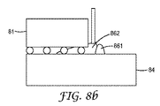
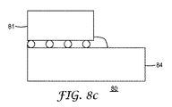
[0004]別の解決策は、図2に示されるように、基板を電子部品に接続するために、オーバーモールド剤を使用することである。図2の実施形態では、半田バンプ(23)を介して基板(24)上に配置される電子部品(21)は、オーバーモールド剤(26)によって被覆される。オーバーモールド剤(26)の縁部(261)が、ボンディングワイヤ等の基板以外の要素に悪影響を及ぼさないようにするために、縁部(261)の位置が制御されなければならない。 [0004] Another solution is to use an overmolding agent to connect the substrate to the electronic component, as shown in FIG. In the embodiment of FIG. 2, the electronic component (21) disposed on the substrate (24) via the solder bump (23) is covered with an overmolding agent (26). In order to prevent the edge (261) of the overmolding agent (26) from adversely affecting elements other than the substrate, such as bonding wires, the position of the edge (261) must be controlled.
[0005]加えて、近年では、半導体パッケージ樹脂組成物は、半導体チップ製造プロセスの効率を高めるために、半導体チップにダイスカットされる前に、半導体ウエファー上に直接コーティングされている。米国特許出願公開第US2006/0194064A1号は、ウエファーが個々のチップにダイスカットされる前に、半導体ウエファー上に直接コーティングされる、硬化性アンダーフィルカプセル材組成物を記載する。ウエファーを個々のチップにダイスカットするために、このアンダーフィル剤は、半導体ウエファー上にコーティングされ、最終的な完全硬化の前に、約100℃〜約150℃の温度でのB段階凝固が実施され、滑らかな非粘着性の固体コーティングが形成される。次いで、ウエファーは、個々のチップにダイスカットされ、アンダーフィル剤を有するB段階処理されたチップは、このアンダーフィル剤が基板に隣接する状態で基板上に配置され、Bステージ変換温度より高い第2の温度で、最終的な完全硬化が実施される。 [0005] In addition, in recent years, semiconductor package resin compositions have been coated directly onto semiconductor wafers before being diced into semiconductor chips to increase the efficiency of the semiconductor chip manufacturing process. US Patent Application Publication No. US 2006/0194064 A1 describes a curable underfill encapsulant composition that is coated directly onto a semiconductor wafer before the wafer is diced into individual chips. In order to dice the wafer into individual chips, this underfill agent is coated onto the semiconductor wafer and subjected to B-stage solidification at a temperature of about 100 ° C. to about 150 ° C. before final full cure. And a smooth non-sticky solid coating is formed. The wafer is then diced into individual chips, and the B-staged chip with the underfill agent is placed on the substrate with the underfill agent adjacent to the substrate, and the wafer is heated above the B stage conversion temperature. A final full cure is performed at a temperature of 2.
[概要]
[0006]本発明の半導体パッケージ樹脂組成物の有益な生成物特質には、基板又は電子部品上で使用される際に低粘度を達成するために適切な範囲の弾性率、熱膨張係数、及びガラス転移点(Tg)、適用の後の組成物の粘度(流動性)を調節する能力、並びに完全硬化の後の基板と電子部品との間又は電子部品間の接続の確実性を保証する能力が挙げられる。加えて、基板又は電子部品の表面上に配置される半導体パッケージの一部分が、その流動性を調節するためにBステージ変換され(つまり、加熱される際に軟化するが融解しないように、組成物の十分な硬化が実施される)、別の部分がBステージ変換されない場合の別の有益な生成物特性には、両方の部分が加熱によって最終的に硬化される場合にさえ、両方の部分が同様の弾性率、熱膨張係数、及びガラス転移点(Tg)を有するということが挙げられる。
[Overview]
[0006] Useful product attributes of the semiconductor package resin composition of the present invention include a suitable range of elastic modulus, thermal expansion coefficient, and to achieve low viscosity when used on a substrate or electronic component, and Ability to adjust glass transition point (Tg), composition viscosity (fluidity) after application, and to ensure the connection between the substrate and the electronic component or between electronic components after complete curing. Is mentioned. In addition, the composition of the semiconductor package disposed on the surface of the substrate or electronic component may be B-stage converted to adjust its fluidity (ie, soften but not melt when heated). Another beneficial product property when the other parts are not B-stage converted is that both parts are even when both parts are finally cured by heating. It has the same elastic modulus, thermal expansion coefficient, and glass transition point (Tg).
[0007]一態様では、本開示は、光での照射による硬化によって流動性を調節することができ、かつ加熱による最終的な硬化を実施することによって、基板と電子部品との間又は電子部品間の確実な接続を保証することができる、半導体パッケージ樹脂組成物を提供する。 [0007] In one aspect, the present disclosure can adjust the fluidity by curing by irradiation with light, and perform final curing by heating to form between a substrate and an electronic component or an electronic component. Provided is a semiconductor package resin composition capable of ensuring reliable connection between the two.
[0008]一実施形態では、本開示は、エポキシ樹脂、硬化剤、無機粒子、及び光重合可能な官能基を含有するシランで表面処理されたナノ粒子を含有する、半導体パッケージ樹脂組成物を含む。 [0008] In one embodiment, the present disclosure includes a semiconductor package resin composition comprising an epoxy resin, a curing agent, inorganic particles, and nanoparticles surface-treated with a silane containing a photopolymerizable functional group. .
[0009]別の実施形態では、本開示は、(1)電子部品及び基板のうちの少なくとも1つを提供することと、(2)電子部品及び/又は基板上に第1の半導体パッケージ樹脂組成物を配置することであって、半導体パッケージ樹脂組成物は、エポキシ樹脂、硬化剤、無機粒子、及び光架橋可能な基を含有するシランで表面処理されたナノ粒子を含有することと、(3)Bステージ変換中に、第1の半導体パッケージ樹脂組成物の少なくとも一部分を光で照射することと、(4)加熱することによって第1の半導体パッケージ樹脂組成物を硬化することと、を含む、半導体パッケージを製造するための方法を提供する。 [0009] In another embodiment, the present disclosure provides (1) providing at least one of an electronic component and a substrate; and (2) a first semiconductor package resin composition on the electronic component and / or substrate. A semiconductor package resin composition comprising an epoxy resin, a curing agent, inorganic particles, and nanoparticles treated with a silane containing a photocrosslinkable group; and (3 ) Irradiating at least a portion of the first semiconductor package resin composition with light during B-stage conversion; and (4) curing the first semiconductor package resin composition by heating. A method for manufacturing a semiconductor package is provided.
[詳細な説明]
[0030]本願において、全ての数字は用語「約」で修飾されているとみなす。終点による数字範囲の詳細説明には、その範囲内に含まれる全ての数が包含される(例えば、1〜5には、1、1.5、2、2.75、3、3.80、4、及び5が包含される)。特に指示しない限り、本明細書で引用された全ての部は重量による。
[Detailed description]
[0030] In this application, all numbers are considered modified by the term "about". A detailed description of a numerical range by endpoint includes all numbers within that range (eg 1 to 5 includes 1, 1.5, 2, 2.75, 3, 3.80, 4 and 5 are included). Unless otherwise indicated, all parts quoted herein are by weight.
[0031]本発明の半導体パッケージ樹脂組成物で使用するのに好適なエポキシ樹脂類には、脂肪族、脂環式、芳香族、若しくは複素環式単量体又はオリゴマーエポキシ化合物類が挙げられるが、これらに限定されない。これらの材料は一般的に、平均で、1分子当たり少なくとも1個の重合可能なエポキシ基を有し、1分子当たり少なくとも1.5個又は少なくとも2個の重合可能なエポキシ基を有してもよい。特定のモードでは、1分子当たり3個又は4個の重合可能なエポキシ基を有する多官能性エポキシ化合物を使用することが可能である。エポキシ化合物は、純化合物であってもよく、又は1分子当たり1個、2個、3個、又はそれ以上のエポキシ基を含有する化合物の混合物であってもよい。 [0031] Epoxy resins suitable for use in the semiconductor package resin composition of the present invention include aliphatic, alicyclic, aromatic, or heterocyclic monomers or oligomeric epoxy compounds. However, it is not limited to these. These materials generally have, on average, at least one polymerizable epoxy group per molecule and at least 1.5 or at least two polymerizable epoxy groups per molecule. Good. In a particular mode, it is possible to use polyfunctional epoxy compounds having 3 or 4 polymerizable epoxy groups per molecule. The epoxy compound may be a pure compound or a mixture of compounds containing one, two, three or more epoxy groups per molecule.
[0032]上述されるエポキシ化合物類は、任意の種類の主鎖を有してもよく、置換基を含有してもよい。好適な置換基の例には、ハロゲン類、エステル基、エーテル類、スルホン酸基、シロキサン基、ニトロ基、リン酸基等が挙げられるが、これらに限定されない。エポキシ化合物のエポキシ当量値は、一般的に、50〜2000の範囲内で変更することができる。 [0032] The epoxy compounds described above may have any type of main chain and may contain substituents. Examples of suitable substituents include, but are not limited to, halogens, ester groups, ethers, sulfonic acid groups, siloxane groups, nitro groups, phosphoric acid groups, and the like. The epoxy equivalent value of the epoxy compound can generally be changed within a range of 50 to 2000.
[0033]オリゴマーエポキシ化合物類の例には、末端エポキシ基を有する直鎖オリゴマー類(例えば、ポリオキシアルキレングリコールのジグリシジルエーテル)、骨格エポキシ単位を有するオリゴマー類(例えば、ポリブタジエンポリエポキシド)、又はペンダントエポキシ基を有するオリゴマー類(例えば、グリシジルメタクリレートオリゴマー若しくはコオリゴマー)が挙げられるが、これらに限定されない。 [0033] Examples of oligomeric epoxy compounds include linear oligomers having terminal epoxy groups (eg, diglycidyl ether of polyoxyalkylene glycol), oligomers having backbone epoxy units (eg, polybutadiene polyepoxide), or pendant. Examples include, but are not limited to, oligomers having an epoxy group (for example, glycidyl methacrylate oligomer or co-oligomer).
[0034]特定のモードでは、以下の式で表されるグリシジルエーテルモノマーを使用することが可能である。

[0035]式中、Rは、nの価数を有するラジカルであり、nは、1〜6の整数である。Rは、芳香族基、脂環式基、脂肪族基、又はこれらの組み合わせであることができる。典型的なエポキシ化合物類には、多価フェノールを過度のエピクロロヒドリン(例えば、2,2−ビス−(2,3−エポキシプロポキシフェノール)−プロパン)等のクロロヒドリンと反応させることによって得られる、多価フェノール類のグリシジルエーテル類が挙げられるが、これに限定されない。具体的には、芳香族エポキシ化合物、脂環式エポキシ化合物、脂肪族エポキシ化合物等を使用することが可能である。
[0034] In a particular mode, it is possible to use a glycidyl ether monomer represented by the following formula:
[0035] In the formula, R is a radical having a valence of n, and n is an integer of 1 to 6. R can be an aromatic group, an alicyclic group, an aliphatic group, or a combination thereof. Typical epoxy compounds are obtained by reacting polyhydric phenols with chlorohydrins such as excess epichlorohydrin (eg, 2,2-bis- (2,3-epoxypropoxyphenol) -propane). And glycidyl ethers of polyhydric phenols, but are not limited thereto. Specifically, an aromatic epoxy compound, an alicyclic epoxy compound, an aliphatic epoxy compound, or the like can be used.
[0036]好適な芳香族エポキシ化合物類には、ビスフェノールAのジグリシジルエーテル(ビスフェノールA型エポキシ樹脂)、ビスフェノールFのジグリシジルエーテル(ビスフェノールF型エポキシ樹脂)、4,4’−ジヒドロキシビフェニルのジグリシジルエーテル、これらのジグリシジルエーテル類のオリゴマー類、クレゾールノボラック樹脂類のポリグリシジルエーテル類(クレゾールノボラック型エポキシ樹脂類)、及びフェノールノボラック樹脂類のポリグリシジルエーテル類(フェノールノボラック型エポキシ樹脂類)が挙げられるが、これらに限定されない。 [0036] Suitable aromatic epoxy compounds include diglycidyl ether of bisphenol A (bisphenol A-type epoxy resin), diglycidyl ether of bisphenol F (bisphenol F-type epoxy resin), 4,4'-dihydroxybiphenyl di- Glycidyl ether, oligomers of these diglycidyl ethers, polyglycidyl ethers of cresol novolac resins (cresol novolac type epoxy resins), and polyglycidyl ethers of phenol novolac resins (phenol novolac type epoxy resins) For example, but not limited to.
[0037]例示的な脂環式エポキシ化合物類には、水素化ビスフェノールA型エポキシ化合物類及び水素化ビスフェノールF型エポキシ化合物類等、上述される芳香族エポキシ化合物類を水素化することによって得られる化合物類が挙げられるが、これに限定されない。加えて、ビニルシクロヘキセンモノオキシド、1,2−エポキシ−4−ビニルシクロヘキサン、1,2:8,9−ジエポキシリモネン、3,4−エポキシシクロヘキセニルメチル−3’,4’−エポキシシクロヘキセンカルボキシレート等のシクロヘキセンオキシド基、及び3,4−エポキシシクロヘキセニルメチル−3,4−エポキシシクロヘキサンカルボキシレート、3,4−エポキシ−2−メチルシクロヘキシルメチル−3,4−エポキシ−2−メチルシクロヘキサンカルボキシレート等のエポキシシクロヘキサンカルボキシレート類、並びにビス(3,4−エポキシ−6−メチルシクロヘキシルメチル)アジペートを含有する化合物類を使用することが可能である。 [0037] Exemplary alicyclic epoxy compounds are obtained by hydrogenating the aromatic epoxy compounds described above, such as hydrogenated bisphenol A type epoxy compounds and hydrogenated bisphenol F type epoxy compounds. Examples include, but are not limited to, compounds. In addition, vinylcyclohexene monoxide, 1,2-epoxy-4-vinylcyclohexane, 1,2: 8,9-diepoxylimonene, 3,4-epoxycyclohexenylmethyl-3 ′, 4′-epoxycyclohexene carboxylate Cyclohexene oxide groups such as 3,4-epoxycyclohexenylmethyl-3,4-epoxycyclohexanecarboxylate, 3,4-epoxy-2-methylcyclohexylmethyl-3,4-epoxy-2-methylcyclohexanecarboxylate, etc. Of epoxycyclohexanecarboxylates, as well as compounds containing bis (3,4-epoxy-6-methylcyclohexylmethyl) adipate can be used.
[0038]好適な脂肪族エポキシ化合物類には、脂肪族多価アルコール類又はそのアルキレンオキシド付加物のグリシジルエーテル類が挙げられるが、これに限定されない。その例として、例えば、エチレングリコールジグリシジルエーテル、ジ(エチレングリコール)ジグリシジルエーテル、プロピレングリコールジグリシジルエーテル、トリ(プロピレングリコール)ジグリシジルエーテル、ネオペンチルグリコールジグリシジルエーテル、1,4−ブタンジオールジグリシジルエーテル、1,6−ヘキサンジオールジグリシジルエーテル、トリメチロールプロパントリグリシジルエーテル、トリメチロールプロパンジグリシジルエーテル、ポリ(エチレングリコール)ジグリシジルエーテル等に言及することができる。 [0038] Suitable aliphatic epoxy compounds include, but are not limited to, aliphatic polyhydric alcohols or glycidyl ethers of alkylene oxide adducts thereof. Examples thereof include ethylene glycol diglycidyl ether, di (ethylene glycol) diglycidyl ether, propylene glycol diglycidyl ether, tri (propylene glycol) diglycidyl ether, neopentyl glycol diglycidyl ether, 1,4-butanediol di Mention may be made of glycidyl ether, 1,6-hexanediol diglycidyl ether, trimethylolpropane triglycidyl ether, trimethylolpropane diglycidyl ether, poly (ethylene glycol) diglycidyl ether and the like.
[0039]上述されるエポキシ樹脂類に加えて、ハロゲン化エポキシ樹脂(臭素化ビスフェノール型エポキシ樹脂等)又はグリシジルアミノ基を有するエポキシ化合物を使用することが可能である。グリシジルアミノ基を有するエポキシ化合物類は、エピハロヒドリンの作用によってアミン類をエポキシド化することによって得られるエポキシ化合物類(エポキシ樹脂類)であり、その例には、アミノフェノール型エポキシ樹脂類、トリグリシジルイソシアヌレート類、テトラグリシジルジアミノジフェニルメタン、テトラグリシジルメタ−キシレンジアミン、及びヘキサグリシジルトリアミノベンゼンが挙げられる。 [0039] In addition to the epoxy resins described above, it is possible to use halogenated epoxy resins (such as brominated bisphenol type epoxy resins) or epoxy compounds having a glycidylamino group. Epoxy compounds having a glycidylamino group are epoxy compounds (epoxy resins) obtained by epoxidizing amines by the action of epihalohydrin. Examples thereof include aminophenol type epoxy resins, triglycidyl isocyanate. Examples include nurates, tetraglycidyl diaminodiphenylmethane, tetraglycidyl meta-xylene diamine, and hexaglycidyl triaminobenzene.
[0040]アミノフェノール型エポキシ樹脂類は、当業者に既知の方法を使用してアミノフェノール類をエポキシ化することによって得られる。アミノフェノール類の例には、2−アミノフェノール、3−アミノフェノール、4−アミノフェノール、2−アミノ−m−クレゾール、2−アミノ−p−クレゾール、3−アミノ−o−クレゾール、4−アミノ−m−クレゾール、及び6−アミノ−m−クレゾール等のアミノフェノール類並びにアミノクレゾール類が挙げられるが、これらに限定されない。 [0040] Aminophenol-type epoxy resins are obtained by epoxidizing aminophenols using methods known to those skilled in the art. Examples of aminophenols include 2-aminophenol, 3-aminophenol, 4-aminophenol, 2-amino-m-cresol, 2-amino-p-cresol, 3-amino-o-cresol, 4-amino Examples include, but are not limited to, aminophenols and aminocresols such as -m-cresol and 6-amino-m-cresol.
[0041]使用するのに好適な他のエポキシ樹脂類には、1つ以上の共重合可能なビニル化合物類を伴う、グリシドールのアクリル酸エステル類(グリシジルアクリレート及びグリシジルメタクリレート等)のコポリマー類が挙げられる。この種類のコポリマーには、スチレン−グリシジルメタクリレート及びメチルメタクリレート−グリシジルアクリレートコポリマーが挙げられる。加えて、また、シリコン原子がエポキシアルキル基で置換されているポリジメチルシロキサンである、エポキシ−官能性シリコンを使用することも可能である。 [0041] Other epoxy resins suitable for use include copolymers of acrylate esters of glycidol (such as glycidyl acrylate and glycidyl methacrylate) with one or more copolymerizable vinyl compounds. It is done. This type of copolymer includes styrene-glycidyl methacrylate and methyl methacrylate-glycidyl acrylate copolymers. In addition, it is also possible to use epoxy-functional silicon, which is polydimethylsiloxane in which the silicon atoms are substituted with epoxyalkyl groups.
[0042]半導体パッケージ樹脂組成物の最終的な硬化の後の特徴の観点から、上述されるエポキシ樹脂類のうち、ビスフェノールA型エポキシ樹脂、ビスフェノールF型エポキシ樹脂、又はアミノフェノール型エポキシ樹脂を使用することが好ましい。加えて、半導体パッケージ樹脂組成物の粘度と最終的な硬化の後の特徴との間のバランスを取る観点から、ビスフェノールA型エポキシ樹脂及びビスフェノールF型エポキシ樹脂の両方、又はビスフェノールA型エポキシ樹脂及びビスフェノールF型エポキシ樹脂にアミノフェノール型エポキシ樹脂を更に添加することによって得られる3成分系を使用することが好ましい。具体的に、両方とも市販されている、製品ZX1059(Nippon Steel Chemical Co.,Ltd.によって製造される、ビスフェノールAとビスフェノールFとの混合物)又はアミノフェノール型エポキシjER(登録商標)630(Mitsubishi Chemical Corporationによって製造される)を使用することが可能である。 [0042] From the viewpoint of the characteristics after final curing of the semiconductor package resin composition, among the epoxy resins described above, bisphenol A type epoxy resin, bisphenol F type epoxy resin, or aminophenol type epoxy resin is used. It is preferable to do. In addition, from the viewpoint of balancing between the viscosity of the semiconductor package resin composition and the characteristics after final curing, both bisphenol A type epoxy resin and bisphenol F type epoxy resin, or bisphenol A type epoxy resin and It is preferable to use a three-component system obtained by further adding an aminophenol type epoxy resin to a bisphenol F type epoxy resin. Specifically, the product ZX1059 (a mixture of bisphenol A and bisphenol F, manufactured by Nippon Steel Chemical Co., Ltd.) or aminophenol type epoxy jER® 630 (Mitsubishi Chemical), both commercially available. (Manufactured by Corporation) can be used.
[0043]エポキシ樹脂のブレンド量は、一般的に、半導体パッケージ樹脂組成物の総量に対して、50質量%以下、幾つかのモードでは10〜40質量%である。 [0043] The blend amount of the epoxy resin is generally 50% by mass or less with respect to the total amount of the semiconductor package resin composition, and 10 to 40% by mass in some modes.
[0044]本発明の半導体パッケージ樹脂組成物に含有される硬化剤は、エポキシ化合物を熱硬化させるために一般的に使用される硬化剤であることができる。その具体的な例には、アミノ化合物類、酸無水物化合物類、アミド化合物類、フェノール化合物類、BF3−モノエタノールアミン等のトリフッ化ホウ素錯体化合物類、2−エチル−4−メチルイミダゾール等のイミダゾール類、アミノジヒドラジド等のヒドラジド類、テトラメチルグアニジン等のグアニジン類、及びジシアンジアミドが挙げられるが、これらに限定されない。硬化剤は、単一の硬化剤又は異なる硬化剤の混合物であることができる。粘度の観点から、酸無水物化合物が好ましい。 [0044] The curing agent contained in the semiconductor package resin composition of the present invention can be a curing agent commonly used to thermally cure an epoxy compound. Specific examples thereof include amino compounds, acid anhydride compounds, amide compounds, phenol compounds, boron trifluoride complex compounds such as BF3-monoethanolamine, and 2-ethyl-4-methylimidazole. Examples include, but are not limited to, imidazoles, hydrazides such as aminodihydrazide, guanidines such as tetramethylguanidine, and dicyandiamide. The curing agent can be a single curing agent or a mixture of different curing agents. From the viewpoint of viscosity, an acid anhydride compound is preferred.
[0045]非芳香族酸無水物化合物を使用することが好適である。例えば、ヘキサヒドロフタル酸無水物、3−メチルヘキサヒドロフタル酸無水物、4−メチルヘキサヒドロフタル酸無水物、1−メチルノルボルナン−2,3−ジカルボン酸無水物、5−メチルノルボルナン−2,3−ジカルボン酸無水物、ノルボルナン−2,3−ジカルボン酸無水物、1−メチルナジック酸無水物、5−メチルナジック酸無水物、ナジック酸無水物、テトラヒドロフタル酸無水物、3−メチルテトラヒドロフタル酸無水物、4−メチルテトラヒドロフタル酸無水物、ドデセニルコハク酸無水物等を使用することが好適である。 [0045] It is preferred to use non-aromatic acid anhydride compounds. For example, hexahydrophthalic anhydride, 3-methylhexahydrophthalic anhydride, 4-methylhexahydrophthalic anhydride, 1-methylnorbornane-2,3-dicarboxylic anhydride, 5-methylnorbornane-2, 3-dicarboxylic acid anhydride, norbornane-2,3-dicarboxylic acid anhydride, 1-methylnadic acid anhydride, 5-methylnadic acid anhydride, nadic acid anhydride, tetrahydrophthalic acid anhydride, 3-methyltetrahydrophthalic acid It is preferable to use an acid anhydride, 4-methyltetrahydrophthalic anhydride, dodecenyl succinic anhydride, or the like.
[0046]これらのうち、化合物中に二重結合を有さない、ヘキサヒドロフタル酸無水物、3−メチルヘキサヒドロフタル酸無水物、4−メチルヘキサヒドロフタル酸無水物、1−メチルノルボルナン−2,3−ジカルボン酸無水物、5−メチルノルボルナン−2,3−ジカルボン酸無水物、又はノルボルナン−2,3−ジカルボン酸無水物が、特に好適である。4−メチルヘキサヒドロフタル酸無水物とヘキサヒドロフタル酸無水物(New Japan Chemical Co.,Ltd.によって製造されるRikacid MH−700(4−メチルヘキサヒドロフタル酸無水物/ヘキサヒドロフタル酸無水物比=70/30)等)との混合物は、この混合物を含有する半導体パッケージ樹脂組成物が低粘度であり、ほとんど結晶化しないため、特に好適である。 [0046] Of these, hexahydrophthalic anhydride, 3-methylhexahydrophthalic anhydride, 4-methylhexahydrophthalic anhydride, 1-methylnorbornane-, which do not have a double bond in the compound 2,3-dicarboxylic anhydride, 5-methylnorbornane-2,3-dicarboxylic anhydride, or norbornane-2,3-dicarboxylic anhydride are particularly preferred. 4-methylhexahydrophthalic anhydride and hexahydrophthalic anhydride (Rikacid MH-700 (4-methylhexahydrophthalic anhydride / hexahydrophthalic anhydride manufactured by New Japan Chemical Co., Ltd.) The mixture with the ratio = 70/30) is particularly suitable because the semiconductor package resin composition containing this mixture has low viscosity and hardly crystallizes.
[0047]例示的なフェノールベースの硬化剤には、ビスフェノールA、ビスフェノールF、ビスフェノールS、4,4’−ビフェニルフェノール、テトラメチルビスフェノールA、ジメチルビスフェノールA、テトラメチルビスフェノールF、ジメチルビスフェノールF、テトラメチルビスフェノールS、ジメチルビスフェノールS、テトラメチル−4,4’−ビフェノール、ジメチル−4,4’−ビフェニルフェノール、1−(4−ヒドロキシフェニル)−2−[4−フェニル]プロパン、2,2’−メチレン−ビス(4−メチル−6−tert−ブチルフェノール)、4,4’−ブチリデン−ビス(3−メチル−6−tert−ブチルフェノール)、トリスヒドロキシフェニルメタン、レゾルシノール、ヒドロキノン、ピロガロール、ジイソプロピリデン、テルペン骨格を有するフェノール類、1,1−ジ−4−ヒドロキシフェニルフルオレン等のフルオレン骨格を有するフェノール類、フェノール化ポリブタジエン類、フェノール、クレゾール類、エチルフェノール類、ブチルフェノール類、オクチルフェノール類、及びビスフェノールA、ビスフェノールF、ビスフェノールS、ナフトール類、テルペンジフェノール類等のフェノール類を原材料として使用して得られるノボラック樹脂類等のノボラック樹脂類、キシリレン骨格を有するフェノールノボラック樹脂類、ジシクロペンタジエン骨格を有するフェノールノボラック樹脂類、ビフェニル骨格を有するフェノールノボラック樹脂類、フルオレン骨格を有するフェノールノボラック樹脂類、及びフラン骨格を有するフェノールノボラック樹脂類が挙げられるが、これらに限定されない。 [0047] Exemplary phenol-based curing agents include bisphenol A, bisphenol F, bisphenol S, 4,4′-biphenylphenol, tetramethyl bisphenol A, dimethyl bisphenol A, tetramethyl bisphenol F, dimethyl bisphenol F, tetra Methyl bisphenol S, dimethyl bisphenol S, tetramethyl-4,4′-biphenol, dimethyl-4,4′-biphenylphenol, 1- (4-hydroxyphenyl) -2- [4-phenyl] propane, 2,2 ′ -Methylene-bis (4-methyl-6-tert-butylphenol), 4,4'-butylidene-bis (3-methyl-6-tert-butylphenol), trishydroxyphenylmethane, resorcinol, hydroquinone, pyrogallol Diisopropylidene, phenols having a terpene skeleton, phenols having a fluorene skeleton such as 1,1-di-4-hydroxyphenylfluorene, phenolized polybutadienes, phenol, cresols, ethylphenols, butylphenols, octylphenols And novolak resins such as novolak resins obtained by using phenols such as bisphenol A, bisphenol F, bisphenol S, naphthols and terpene diphenols as raw materials, phenol novolac resins having a xylylene skeleton, dicyclo Phenol novolac resins having a pentadiene skeleton, phenol novolac resins having a biphenyl skeleton, phenol novolac resins having a fluorene skeleton, and a furan skeleton Phenol novolac resins include, but are not limited to.
[0048]例示的なアミノベースの硬化剤には、ジエチレントリアミン、トリエチレンテトラミン、又はテトラエチレンペンタミン等の脂肪族アミン類、ジアミノジフェニルメタン等の芳香族アミン類、ジアミノジフェニルスルホン、メタ−キシレンジアミン、及び芳香族アミン類とアルデヒド類との縮合生成物類、ポリアミドアミン類が挙げられるが、これらに限定されない。 [0048] Exemplary amino-based curing agents include aliphatic amines such as diethylenetriamine, triethylenetetramine, or tetraethylenepentamine, aromatic amines such as diaminodiphenylmethane, diaminodiphenylsulfone, meta-xylenediamine, And condensation products of aromatic amines and aldehydes, and polyamidoamines, but are not limited thereto.
[0049]得られる硬化生成物の特徴の観点から、硬化剤のブレンド量は、エポキシ樹脂のブレンド量とほぼ等しい。広くは、硬化剤のブレンド量は、半導体パッケージ樹脂組成物の総重量に対して5〜15質量%である。 [0049] From the viewpoint of the characteristics of the obtained cured product, the blend amount of the curing agent is approximately equal to the blend amount of the epoxy resin. In general, the blend amount of the curing agent is 5 to 15% by mass with respect to the total weight of the semiconductor package resin composition.
[0050]無機粒子は、本発明の半導体パッケージ樹脂組成物中に実質的に均質に分散される。無機粒子は、半導体パッケージ樹脂組成物に高弾性率及び低熱膨張係数を付与するために使用され、単一の種類の無機粒子又は2つ以上の種類の無機粒子の組み合わせを使用することが可能である。広くは、これらの無機粒子は、シリカ(溶融シリカ、結晶シリカ)、アルミナ、ケイ酸カルシウム、炭酸カルシウム、チタン酸カリウム、炭化ケイ素、窒化ケイ素、窒化アルミニウム、窒化ホウ素、ベリリア、ジルコニア、ジルコン、フォステライト、ステアタイト、スピネル、ムライト、若しくはチタニア等の粉末、又はこれらの粉末を球状にすることによって得られるビーズ、ガラス繊維等であることができる。単一の種類の無機粒子又は2つ以上の種類のこれらの無機粒子の組み合わせを使用することができる。 [0050] The inorganic particles are substantially uniformly dispersed in the semiconductor package resin composition of the present invention. The inorganic particles are used to impart a high elastic modulus and a low thermal expansion coefficient to the semiconductor package resin composition, and it is possible to use a single type of inorganic particles or a combination of two or more types of inorganic particles. is there. In general, these inorganic particles are silica (fused silica, crystalline silica), alumina, calcium silicate, calcium carbonate, potassium titanate, silicon carbide, silicon nitride, aluminum nitride, boron nitride, beryllia, zirconia, zircon, phosphor. It can be a powder of stellite, steatite, spinel, mullite, titania or the like, or a bead, glass fiber or the like obtained by making these powders spherical. A single type of inorganic particles or a combination of two or more types of these inorganic particles can be used.
[0051]上述される無機粒子のうち、溶融シリカは、熱膨張特性の観点から特に好適であり、結晶シリカ及びアルミナは、高熱伝導率を有するという観点から特に好適である。加えて、有機ゾルから無機粒子としてシリカ粒子を生成する際、その粒子サイズ分布が狭いため、粒子を樹脂組成物中に効果的に分布させることが可能である。更に、無機粒子の一次粒子の形状は特に重要ではないが、流動して微細な間隙に侵入することができるという観点から、球状の粒子が好ましい。 [0051] Of the inorganic particles described above, fused silica is particularly suitable from the viewpoint of thermal expansion characteristics, and crystalline silica and alumina are particularly suitable from the viewpoint of having high thermal conductivity. In addition, when silica particles are generated as inorganic particles from an organic sol, the particle size distribution is narrow, so that the particles can be effectively distributed in the resin composition. Further, the shape of the primary particles of the inorganic particles is not particularly important, but spherical particles are preferable from the viewpoint of being able to flow and enter fine gaps.
[0052]加えて、半導体パッケージ樹脂組成物の流動性の観点から、無機粒子は、小さい平均粒径及び狭い粒子サイズ分布を有する。無機粒子は、半導体パッケージ樹脂組成物が狭い間隙に押し込まれる際に積み重なる傾向があるため、本発明で使用される無機粒子は、10μm以下の平均粒径を有する。一実施形態では、無機粒子の平均粒径は、具体的には5μm以下、より具体的には3μm以下、及び更により具体的には2μm以下である。しかしながら、無機粒子の平均粒径の下限は特に制限されていないが、流動性の観点から、平均粒径は、シリカ粒子の場合では0.05μm以上、及びアルミナ粒子の場合では0.1μm以上である。一実施形態では、半導体パッケージ樹脂組成物中の無機粒子の粒径は、「平均粒径±(平均粒径×0.3)」(例えば、1±0.3μm)の範囲内である。電子顕微鏡又はレーザー散乱装置を用いて、無機粒子の平均粒径及び粒子サイズ分布を測定することができる。更に、無機粒子は、樹脂組成物中への粒子の分散性を損なわない程度に表面処理されてもよい。 [0052] In addition, from the viewpoint of fluidity of the semiconductor package resin composition, the inorganic particles have a small average particle size and a narrow particle size distribution. Since the inorganic particles tend to accumulate when the semiconductor package resin composition is pushed into a narrow gap, the inorganic particles used in the present invention have an average particle size of 10 μm or less. In one embodiment, the average particle size of the inorganic particles is specifically 5 μm or less, more specifically 3 μm or less, and even more specifically 2 μm or less. However, the lower limit of the average particle size of the inorganic particles is not particularly limited, but from the viewpoint of fluidity, the average particle size is 0.05 μm or more in the case of silica particles and 0.1 μm or more in the case of alumina particles. is there. In one embodiment, the particle size of the inorganic particles in the semiconductor package resin composition is in the range of “average particle size ± (average particle size × 0.3)” (for example, 1 ± 0.3 μm). The average particle diameter and particle size distribution of the inorganic particles can be measured using an electron microscope or a laser scattering apparatus. Furthermore, the inorganic particles may be surface-treated to such an extent that the dispersibility of the particles in the resin composition is not impaired.
[0053]ゾル−ゲル方法によって調製され、狭い粒子サイズ分布を有するシリカ粒子は、無機粒子として特に好適であり、ゾル−ゲル方法によって調製され、狭い粒子サイズ分布(平均粒径±(平均粒径×0.3))を有し、0.8〜1.8μmの平均粒径を有する溶融シリカは、更により好適である。そのような無機粒子は、例えば、シリカKE−S150及びKE−S10(Nippon Shokubai Co.,Ltd.によって、ゾル−ゲル方法を使用して製造される)、シリカHPS−1000(Toagosei Co.,Ltd.によって、ゾル−ゲル方法によって製造される)、又はシリカSS−07、SS−10、及びSS−14(Tokuyama Corporationによって、ゾル−ゲル方法によって製造される)として市販されている。 [0053] Silica particles prepared by the sol-gel method and having a narrow particle size distribution are particularly suitable as inorganic particles, and prepared by the sol-gel method, the narrow particle size distribution (average particle size ± (average particle size Fused silica having an average particle size of 0.8 to 1.8 μm is even more preferred. Such inorganic particles include, for example, silica KE-S150 and KE-S10 (manufactured by Nippon Shokubai Co., Ltd. using a sol-gel method), silica HPS-1000 (Toagosei Co., Ltd. Manufactured by the sol-gel process), or commercially available as silica SS-07, SS-10, and SS-14 (manufactured by the Tokuyama Corporation by the sol-gel process).
[0054]本発明の半導体パッケージ樹脂組成物は、光重合可能な官能基を含有するシランで表面処理されたナノ粒子を含有する。光(例えば、紫外線及び/又は可視光)に暴露することによって、短期間(数秒間から数十秒間)照射することによって、樹脂組成物の流動性を調節すること、及びBステージ変換を実施する(つまり、加熱される際に軟化するが融解しないように、組成物の十分な硬化を実施する)ことが可能である。 [0054] The semiconductor package resin composition of the present invention contains nanoparticles surface-treated with a silane containing a photopolymerizable functional group. Adjusting the fluidity of the resin composition by exposing it to light (for example, ultraviolet rays and / or visible light), irradiating it for a short period (several seconds to several tens of seconds), and performing B-stage conversion (That is, sufficient curing of the composition is performed so that it softens but does not melt when heated).
[0055]広くは、これらのナノ粒子は、シリカ(例えば、溶融シリカ又は結晶シリカ)、アルミナ、ケイ酸化カルシウム、炭酸カルシウム、チタン酸カリウム、炭化ケイ素、窒化ケイ素、窒化アルミニウム、窒化ホウ素、ベリリア、ジルコニア、ジルコン、フォステライト、ステアタイト、スピネル、ムライト、若しくはチタニア等の粉末、又はこれらの粉末を球状にすることによって得られるビーズ、ガラス繊維等であることができる。単一の種類の無機粒子又は2つ以上の種類のこれらの無機粒子の組み合わせを使用することができる。 [0055] Broadly, these nanoparticles are silica (eg, fused silica or crystalline silica), alumina, calcium silicate, calcium carbonate, potassium titanate, silicon carbide, silicon nitride, aluminum nitride, boron nitride, beryllia, It can be a powder of zirconia, zircon, fosterite, steatite, spinel, mullite, titania or the like, or beads, glass fibers, etc. obtained by making these powders spherical. A single type of inorganic particles or a combination of two or more types of these inorganic particles can be used.
[0056]ナノ粒子のうち、シリカ粒子は、化学安定性の観点から特に好適であり、アルミナは、熱伝導率の観点から好ましい。加えて、有機ゾルからナノ粒子としてシリカ粒子を生成する際、その粒子サイズ分布が狭いため、粒子を樹脂組成物中に効果的に分布させることが可能である。更に、ナノ粒子の形状は特に重要ではないが、球状の粒子は、流動して微細な間隙に侵入することができるという観点から特に好適である。 [0056] Among the nanoparticles, silica particles are particularly preferable from the viewpoint of chemical stability, and alumina is preferable from the viewpoint of thermal conductivity. In addition, when silica particles are produced as nanoparticles from an organic sol, the particle size distribution is narrow, so that the particles can be effectively distributed in the resin composition. Further, the shape of the nanoparticles is not particularly important, but spherical particles are particularly preferable from the viewpoint that they can flow and penetrate into fine gaps.
[0057]本発明の組成物で使用するのに好適なナノ粒子は、1nm〜1μm未満の範囲内の平均粒径を有する。光重合可能な官能基の反応性を向上させるために、ナノ粒子の平均粒径は、好ましくは小さい。一般的に、ナノ粒子の平均粒径は、5nm〜500nm、具体的には10nm〜300nm、及びより具体的には10nm〜100nmであることができる。 [0057] Nanoparticles suitable for use in the compositions of the present invention have an average particle size in the range of 1 nm to less than 1 μm. In order to improve the reactivity of the photopolymerizable functional group, the average particle size of the nanoparticles is preferably small. In general, the average particle size of the nanoparticles can be 5 nm to 500 nm, specifically 10 nm to 300 nm, and more specifically 10 nm to 100 nm.
[0058]光によって重合することができる官能基には、CH2=CH−C(=O)−O−基、CH2=CCH3−C(=O)−O−基、グリシジル基、ビニル基等が挙げられる。 [0058] Functional groups that can be polymerized by light include CH 2 ═CH—C (═O) —O— group, CH 2 ═CCH 3 —C (═O) —O— group, glycidyl group, vinyl Groups and the like.
[0059]光重合可能な官能基を含有するシランは、3−(トリメトキシシリル)プロピルメタクリレート、ビニルトリメトキシシラン、ビニルトリエトキシシラン、p−スチリルトリメトキシシラン、又は3−メタクリルオキシプロピルトリメトキシシラン、3−メタクリルオキシプロピルトリメトキシシラン、メチルジメトキシシラン、若しくは3−アクリルオキシプロピルトリメトキシシラン等の(メタ)アクリレートシランであることができる。これらは、化学結合(共有結合若しくはイオン結合)又は強力な物理結合のいずれかによって、ナノ粒子の表面に結合することができる。 [0059] The silane containing a photopolymerizable functional group is 3- (trimethoxysilyl) propyl methacrylate, vinyltrimethoxysilane, vinyltriethoxysilane, p-styryltrimethoxysilane, or 3-methacryloxypropyltrimethoxy. It can be a (meth) acrylate silane such as silane, 3-methacryloxypropyltrimethoxysilane, methyldimethoxysilane, or 3-acryloxypropyltrimethoxysilane. They can be bound to the surface of the nanoparticles by either chemical bonds (covalent or ionic bonds) or strong physical bonds.
方法
[0060]例えば、以下の方法を使用して、光重合可能な官能基を含有するシランで表面処理されたナノ粒子を調製することができる。
Methods [0060] For example, the following method can be used to prepare nanoparticles surface-treated with a silane containing a photopolymerizable functional group.
[0061]液体は、光重合可能な官能基を含有するシランを溶媒に添加し、次いでこの液体をコロイドシリカに撹拌しながら添加することによって調製される。撹拌した後、高温で10〜20時間加熱することによって、表面修飾ナノ粒子を含有する反応混合物が得られる。 [0061] The liquid is prepared by adding a silane containing a photopolymerizable functional group to a solvent and then adding the liquid to colloidal silica with stirring. After stirring, the reaction mixture containing the surface-modified nanoparticles is obtained by heating at a high temperature for 10 to 20 hours.
[0062]反応混合物は次いで、室温に冷却され、ロータリーエバポレーターの手段によって、混合物から水が除去される。次に、溶媒が添加され、蒸発器の手段によって、いかなる残りの水も除去される(この工程は、数回繰り返されてもよい)。次いで、その中の固体内容物を調節するために、反応混合物に溶媒が添加される。反応混合物分散は次いで、溶媒中の堆積物を除去し、光重合可能な官能基を含有するシランで表面処理されたナノ粒子を含有する分散を得るために、1.0μmのガラスマイクロファイバーフィルタを通してフィルタ処理される。 [0062] The reaction mixture is then cooled to room temperature and water is removed from the mixture by means of a rotary evaporator. The solvent is then added and any remaining water is removed by means of an evaporator (this process may be repeated several times). A solvent is then added to the reaction mixture to adjust the solid content therein. The reaction mixture dispersion is then passed through a 1.0 μm glass microfiber filter to remove deposits in the solvent and obtain a dispersion containing nanoparticles surface-treated with silane containing photopolymerizable functional groups. Filtered.
[0063]半導体パッケージ樹脂組成物中の無機粒子及び光重合可能な官能基を含有するシランで表面処理されたナノ粒子の量は、得られる硬化物質の熱膨張係数の観点から、半導体パッケージ樹脂組成物の全体量に対して60質量%以上であり、樹脂組成物の粘度の観点から、半導体パッケージ樹脂組成物の全体量に対して90質量%以下である。無機粒子のブレンド量がこの範囲内である場合、一般的に、35ppm以下の熱膨張係数を有する硬化生成物を得ることが可能であり、また、本発明の半導体パッケージ樹脂組成物を半導体パッケージ樹脂組成物として使用することも可能である。 [0063] The amount of nanoparticles surface-treated with silane containing inorganic particles and photopolymerizable functional groups in the semiconductor package resin composition is determined from the viewpoint of the thermal expansion coefficient of the resulting cured material. It is 60 mass% or more with respect to the whole quantity of a thing, and 90 mass% or less with respect to the whole quantity of a semiconductor package resin composition from a viewpoint of the viscosity of a resin composition. When the blend amount of the inorganic particles is within this range, it is generally possible to obtain a cured product having a thermal expansion coefficient of 35 ppm or less, and the semiconductor package resin composition of the present invention is used as a semiconductor package resin. It can also be used as a composition.
[0064]光重合可能な官能基を含有するシランで表面処理されたナノ粒子の量は、ナノ粒子及び無機粒子の総量に対して、0.1質量%以上かつ10質量%以下である。Bステージ変換が実施される場合、樹脂組成物の所望の粘度(流動性)を得るために、添加されるナノ粒子の量が調節される。光重合可能な官能基を含有するシランで表面処理されたナノ粒子の量が少なすぎる場合、光で照射される際にさえ、樹脂組成物の粘度(流動性)を調節することができず、この量が多すぎる場合、完全硬化が生じ、光での照射に続く熱硬化中に硬化収縮が生じ、硬化生成物内に亀裂が現れる。 [0064] The amount of nanoparticles surface-treated with a silane containing a photopolymerizable functional group is 0.1% by mass or more and 10% by mass or less based on the total amount of nanoparticles and inorganic particles. When B-stage conversion is performed, the amount of nanoparticles added is adjusted to obtain the desired viscosity (fluidity) of the resin composition. If the amount of nanoparticles surface-treated with a silane containing a photopolymerizable functional group is too small, the viscosity (fluidity) of the resin composition cannot be adjusted even when irradiated with light, If this amount is too high, complete cure will occur, cure shrinkage will occur during thermal curing following irradiation with light, and cracks will appear in the cured product.
[0065]本発明の半導体パッケージ樹脂組成物に光重合反応開始剤を添加することは、特に好適である。光重合反応開始剤の例には、ベンゾイン、ベンゾインメチルエーテル、ベンゾインエチルエーテル、ベンゾインn−プロピルエーテル、ベンゾインn−ブチルエーテル、ベンジル、ベンゾフェノン、p−メチルベンゾフェノン、ジアセチル、エオシン、チオニン、ミヒラーケトン、アセトフェノン、2−クロロチオキサントン、アントラキノン、クロロアントラキノン、2−メチルアントラキノン、α−ヒドロキシイソブチルフェノン、p−イソプロピル−α−ヒドロキシイソブチルフェノン、α,α’−ジクロロ−4−フェノキシアセトフェノン、1−ヒドロキシ−1−シクロヘキシルアセトフェノン、2,2−ジメトキシ−2−フェニルアセトフェノン、メチルベンゾインホルメート、2−メチル−1−[4−(メチルチオ)フェニル]−2−モルホリノプロペン、ジクロロチオキサントン、ジイソプロピルチオキサントン、フェニルジスルフィド−2−ニトロソフルオレン、ブチロイン、アニソイソエチル(anisoisoethyl)エーテル、アゾビスイソブチロニトリル、テトラメチルチウラムジスルフィド等が挙げられるが、これらに限定されない。その1つ以上の種類が使用されてもよい。 [0065] It is particularly preferable to add a photopolymerization initiator to the semiconductor package resin composition of the present invention. Examples of photopolymerization initiators include benzoin, benzoin methyl ether, benzoin ethyl ether, benzoin n-propyl ether, benzoin n-butyl ether, benzyl, benzophenone, p-methylbenzophenone, diacetyl, eosin, thionine, Michler's ketone, acetophenone, 2-chlorothioxanthone, anthraquinone, chloroanthraquinone, 2-methylanthraquinone, α-hydroxyisobutylphenone, p-isopropyl-α-hydroxyisobutylphenone, α, α'-dichloro-4-phenoxyacetophenone, 1-hydroxy-1-cyclohexyl Acetophenone, 2,2-dimethoxy-2-phenylacetophenone, methylbenzoinformate, 2-methyl-1- [4- (methylthio) phenyl]- - morpholino-propene, dichloro thioxanthone, diisopropyl thioxanthone, phenyl disulfide 2-nitroso fluorene, butyroin, Anisoisoechiru (anisoisoethyl) ether, azobisisobutyronitrile, although tetramethylthiuram disulfide, but not limited to. One or more of the types may be used.
[0066]半導体パッケージ樹脂組成物に有機チタン化合物が添加されてもよい。有機チタン化合物は、化合物中に加水分解性基又は疎水基を有してもよい。そのような有機チタン化合物類は、一般的に、チタンカップリング剤として知られている。有機チタン化合物は、無機粒子の表面上の−OH基と反応し、加水分解によってアルコールを排除することによって、例えば、チタンとの共有結合を形成する。理論に束縛されるものではないが、これは、無機粒子の表面を有機化し、これは、エポキシ樹脂中の無機粒子の良好な分散性をもたらすと考えられる。 [0066] An organic titanium compound may be added to the semiconductor package resin composition. The organic titanium compound may have a hydrolyzable group or a hydrophobic group in the compound. Such organic titanium compounds are generally known as titanium coupling agents. The organotitanium compound reacts with —OH groups on the surface of the inorganic particles and eliminates alcohol by hydrolysis, thereby forming a covalent bond with, for example, titanium. Without being bound by theory, it is believed that this organicizes the surface of the inorganic particles, which leads to good dispersibility of the inorganic particles in the epoxy resin.
[0067]有機化合物中の加水分解性基は、例えば、R1O−、−O−CH2−CH2−O−、又は−O−CH2−C(=O)−O−等であることができる。ここで、R1は、置換された、若しくは非置換の直鎖又は分枝鎖アルキル基、アルケニル基、アリール基、あるいはアラルキル基であることができる。R1は、無機粒子との反応の後に排除される(例えば、アルコールを形成することによって排除される)ため、R1は、排除の後に幾らか低い沸点を有する基であることが好ましい。したがって、特に好適なR1は、少数の炭素原子を有する基、及び具体的には、1〜10個の炭素原子(及びより具体的には1〜8個の炭素原子)を有する、置換された、若しくは非置換の直鎖又は分枝鎖アルキル基である。 [0067] hydrolyzable group of the organic compound is, for example, R 1 O -, - O -CH 2 -CH 2 -O-, or is -O-CH 2 -C (= O ) -O- , etc. be able to. Here, R 1 may be a substituted or unsubstituted linear or branched alkyl group, alkenyl group, aryl group, or aralkyl group. Since R 1 is excluded after reaction with inorganic particles (eg, excluded by forming an alcohol), R 1 is preferably a group having a somewhat lower boiling point after exclusion. Thus, particularly preferred R 1 is a substituted group having a small number of carbon atoms, and specifically having 1 to 10 carbon atoms (and more specifically 1 to 8 carbon atoms). Or an unsubstituted linear or branched alkyl group.
[0068]加えて、有機チタン化合物中の疎水基は、−O−C(=O)−R2、−O−S(=O)2−Ph−R2、−O−P(=O)(−OH)−O−P(=O)−(OR2)2、−O−P(=O)−(OR2)2、HO−P−(OR2)2、−O−(CH2)m−NH−(CH2)n−NH2等であることができる。ここで、Phは、フェニル基を示し、m及びnはそれぞれ、1〜10の整数であり、R2は、置換された、若しくは非置換の直鎖又は分枝鎖アルキル基、アルケニル基、アリール基、あるいはアラルキル基であることができる。無機粒子の表面が被覆される効率を改善するために、R2は、具体的には、多くの炭素原子を有する基、及びより具体的には、8〜30個の炭素原子を有する、置換された、若しくは非置換の直鎖又は分枝鎖アルキル基である。 [0068] In addition, the hydrophobic group of the organic titanium compound is, -O-C (= O) -R 2, -O-S (= O) 2 -Ph-R 2, -O-P (= O) (-OH) -O-P (= O) - (OR 2) 2, -O-P (= O) - (OR 2) 2, HO-P- (OR 2) 2, -O- (CH 2 ) m-NH- (CH 2) may be an n-NH 2 and the like. Here, Ph represents a phenyl group, m and n are each an integer of 1 to 10, and R 2 is a substituted or unsubstituted linear or branched alkyl group, alkenyl group, aryl Group or an aralkyl group. In order to improve the efficiency with which the surface of the inorganic particles is coated, R 2 is specifically a group having many carbon atoms, and more specifically a substitution having 8 to 30 carbon atoms. Or a substituted or unsubstituted linear or branched alkyl group.
[0069]これらのうち、−O−C(=O)−R2、HO−P−(OR2)2、及び−O−(CH2)m−NH−(CH2)n−NH2は、半導体パッケージ樹脂組成物中の無機粒子との反応性、及び半導体パッケージ樹脂組成物の低減した粘度の観点から、特に好適な疎水基である。流動性の観点から、−O−C(=O)−R2又はHO−P−(OR2)2がより好適であり、チタンカップリング剤の安定性の観点から、−O−C(=O)−R2がより好適である。ここで、R2は、8〜30個の炭素原子、及び好ましくは10〜30個の炭素原子を有する、置換された、若しくは非置換の直鎖又は分枝鎖アルキル基である。 [0069] Of these, -O-C (= O) -R 2, HO-P- (OR 2) 2, and -O- (CH 2) m-NH- (CH 2) n-NH 2 is From the viewpoint of reactivity with inorganic particles in the semiconductor package resin composition and reduced viscosity of the semiconductor package resin composition, this is a particularly preferred hydrophobic group. From the viewpoint of fluidity, —O—C (═O) —R 2 or HO—P— (OR 2 ) 2 is more preferable. From the viewpoint of stability of the titanium coupling agent, —O—C (= O) -R 2 is more preferred. Here, R 2 is a substituted or unsubstituted linear or branched alkyl group having 8 to 30 carbon atoms, and preferably 10 to 30 carbon atoms.
[0070]具体的に、チタンカップリング剤は、例えば、テトラアルコキシチタン(テトラエトキシチタン、テトライソプロポキシチタン、又はテトラブトキシチタン等)、テトラ(エチレングリコール)チタネート、ジ−n−ブチルビス(トリエタノールアミン)チタネート、ジ−イソプロポキシビス(アセチルアセトナート)チタン、イソプロポキシチタンオクタノエート、イソプロピルチタントリメタクリレート、イソプロピルチタントリアクリレート、イソプロピルトリイソステアロイルチタネート、イソプロピルトリデシルベンゼンスルホニルチタネート、イソプロピルトリ(ブチル、メチルピロホスフェート)チタネート、テトライソプロピルジ(ジラウリルホスファイト)チタネート、ジメタクリルオキシアセテートチタネート、ジアクリルオキシアセテートチタネート、ジ(ジオクチルホスファイト)エチレンチタネート、イソプロポキシチタントリ(ジオクチルホスフェート)、イソプロピルトリス(ジオクチルピロホスフェート)チタネート、テトライソプロピルビス(ジオクチルホスファイト)チタネート、テトラオクチルビス(ジ−トリデシルホスファイト)チタネート、テトラ(2,2−ジアリルオキシメチル−1−ブチル)ビス(ジ−トリデシル)ホスファイトチタネート、ビス(ジオクチルピロホスフェート)オキシアセテートチタネート、トリス(ジオクチルピロホスフェート)エチレンチタネート、イソプロピルトリ−n−ドデシルベンゼンスルホニルチタネート、イソプロピルトリオクタノイルチタネート、イソプロピルジメタクリロイルイソステアロイルチタネート、イソプロピルイソステアロイルジアクリルチタネート、イソプロピルトリ(ジオクチルホスフェート)チタネート、イソプロピルトリクミルフェニルチタネート、イソプロピルトリ(N−アミノエチル−アミノエチル)チタネート等であることができる。 [0070] Specifically, the titanium coupling agent includes, for example, tetraalkoxytitanium (tetraethoxytitanium, tetraisopropoxytitanium, tetrabutoxytitanium, etc.), tetra (ethylene glycol) titanate, di-n-butylbis (triethanol Amine) titanate, di-isopropoxybis (acetylacetonate) titanium, isopropoxytitanium octanoate, isopropyl titanium trimethacrylate, isopropyl titanium triacrylate, isopropyl triisostearoyl titanate, isopropyl tridecylbenzenesulfonyl titanate, isopropyl tri (butyl) , Methyl pyrophosphate) titanate, tetraisopropyl di (dilauryl phosphite) titanate, dimethacryloxyacetate titanate , Diacryloxy acetate titanate, di (dioctyl phosphite) ethylene titanate, isopropoxy titanium tri (dioctyl phosphate), isopropyl tris (dioctyl pyrophosphate) titanate, tetraisopropyl bis (dioctyl phosphite) titanate, tetraoctyl bis (di -Tridecyl phosphite) titanate, tetra (2,2-diallyloxymethyl-1-butyl) bis (di-tridecyl) phosphite titanate, bis (dioctyl pyrophosphate) oxyacetate titanate, tris (dioctyl pyrophosphate) ethylene titanate , Isopropyl tri-n-dodecylbenzenesulfonyl titanate, isopropyl trioctanoyl titanate, isopropyl dimethacryloyl Isostearoyl titanate, isopropyl isostearoyl diacryl titanate, isopropyl tri (dioctyl phosphate) titanate, isopropyl tricumylphenyl titanate, isopropyl tri - can (N- aminoethyl-aminoethyl) is titanate.
[0071]Ajinomoto Fine−Techno Co.,Inc.によって販売される、Plenact(登録商標)シリーズのKRTTS(イソプロピルトリイソステアロイルチタネート(CH3)2CHOTi[OCO(CH2)14CH(CH3)2]3)、KR 46B(テトラオクチルビス(ジ−トリデシルホスファイト)チタネート)、KR 55(テトラ(2,2−ジアリルオキシメチル−1−ブチル)ビス(ジ−トリデシル)ホスファイトチタネート)、KR 41B(テトライソプロピルビス(ジオクチルホスファイト)チタネート)、KR 38S(イソプロピルトリス(ジオクチルピロホスフェート)チタネート)、KR 138S(ビス(ジオクチルピロホスフェート)オキシアセテートチタネート)、KR 238S(トリス(ジオクチルピロホスフェート)エチレンチタネート)、338X(イソプロピルジオクチルピロホスフェートチタネート)、KR 44(イソプロピルトリ(N−アミノエチルアミノエチル)チタネート)、KR 9SA(イソプロピルトリス(ドデシルベンジルフェニル)チタネート等を使用することができる。Plenact KR TTS、KR 46B、及びKR 9SAは、好適であり、Plenact KR TTS及びKR 46Bは、より好適である。 [0071] Ajinomoto Fine-Techno Co. , Inc. Plenact® series KRTTS (Isopropyltriisostearoyl titanate (CH 3 ) 2 CHOTi [OCO (CH 2 ) 14 CH (CH 3 ) 2 ] 3 ), KR 46B (tetraoctyl bis (di) -Tridecyl phosphite) titanate), KR 55 (tetra (2,2-diallyloxymethyl-1-butyl) bis (di-tridecyl) phosphite titanate), KR 41B (tetraisopropyl bis (dioctyl phosphite) titanate) , KR 38S (isopropyl tris (dioctyl pyrophosphate) titanate), KR 138S (bis (dioctyl pyrophosphate) oxyacetate titanate), KR 238S (tris (dioctyl pyrophosphate) ethylene titanate ) 338X (isopropyl dioctyl pyrophosphate titanate), KR 44 (isopropyl tri (N-aminoethylaminoethyl) titanate), KR 9SA (isopropyl tris (dodecylbenzylphenyl) titanate, etc.) Plenact KR TTS, KR 46B and KR 9SA are preferred, and Plenact KR TTS and KR 46B are more preferred.
[0072]半導体パッケージ樹脂組成物の粘度を低減するという観点から、有機チタン化合物のブレンド量は、半導体パッケージ樹脂組成物の総量に対して1質量%以上、具体的には2質量%以上、及びより具体的には2.5質量%以上である。しかしながら、得られる硬化生成物の低下したガラス転移温度及び弾性率の観点から、有機チタン化合物のブレンド量は、半導体パッケージ樹脂組成物の総量に対して5質量%以下、具体的には4質量%以下、及びより具体的には3質量%以下である。 [0072] From the viewpoint of reducing the viscosity of the semiconductor package resin composition, the blend amount of the organic titanium compound is 1% by mass or more, specifically 2% by mass or more with respect to the total amount of the semiconductor package resin composition, and More specifically, it is 2.5% by mass or more. However, from the viewpoint of the reduced glass transition temperature and elastic modulus of the obtained cured product, the blend amount of the organic titanium compound is 5% by mass or less, specifically 4% by mass with respect to the total amount of the semiconductor package resin composition. Below, and more specifically, it is 3 mass% or less.
[0073]有機リン酸化合物類の中で、本発明の半導体パッケージ樹脂組成物で使用することができるリン酸エステル類には、リン酸及びアルコールを脱水縮合させることによって得られるエステル類が挙げられるが、これに限定されない。リン酸エステルを上述の有機チタン化合物に更に添加することによって、リン酸エステルは、チタンとの配位結合等の弱結合を形成する。結果として、有機チタン化合物によって有機化される無機粒子の表面上の有機層は、深さが増す。 [0073] Among the organic phosphate compounds, the phosphate esters that can be used in the semiconductor package resin composition of the present invention include esters obtained by dehydration condensation of phosphoric acid and alcohol. However, it is not limited to this. By further adding a phosphate ester to the above-mentioned organic titanium compound, the phosphate ester forms a weak bond such as a coordination bond with titanium. As a result, the organic layer on the surface of the inorganic particles that are organized by the organotitanium compound increases in depth.
[0074]具体的に、リン酸エステルは、リン酸(O−P(OH)3)中の3個の水素原子の全て又はそのうちの幾つかが有機基によって置換される構造を有する。1個、2個、及び3個の水素原子が置換される化合物は、それぞれ、リン酸モノエステル(P(OZ)3)、リン酸ジエステル(HOP(OZ)2)、及びリン酸トリエステル((HO)2POZ)として既知である。ここで、Zは、10〜50個の炭素原子を有する、置換された、若しくは非置換のアルキル基、フェニル基、ポリエステル、又はポリカプロラクトン等を示す。無機粒子の表面上に形成される有機層の厚さを増加させるという観点から、Zは特に、高分子量を有する。具体的には200〜20,000の重量平均分子量、及びより具体的には300〜10,000の重量平均分子量である。 [0074] Specifically, the phosphate ester has a structure in which all or some of the three hydrogen atoms in phosphoric acid (OP (OH) 3 ) are replaced by organic groups. Compounds in which one, two, and three hydrogen atoms are substituted are phosphoric monoester (P (OZ) 3 ), phosphoric diester (HOP (OZ) 2 ), and phosphoric triester ( (HO) 2 POZ). Here, Z represents a substituted or unsubstituted alkyl group, phenyl group, polyester, polycaprolactone or the like having 10 to 50 carbon atoms. From the viewpoint of increasing the thickness of the organic layer formed on the surface of the inorganic particles, Z particularly has a high molecular weight. Specifically, the weight average molecular weight is 200 to 20,000, and more specifically, the weight average molecular weight is 300 to 10,000.
[0075]例えば、ジメチルホスフェート、ジエチルホスフェート、ジプロピルホスフェート、モノブチルホスフェート、ジブチルホスフェート、モノ−2−エチルヘキシルホスフェート、ジ−2−エチルヘキシルホスフェート、モノフェニルホスフェート、モノ−2−エチルヘキシルホスファイト、ジオクチルホスフェート、ジフェニルホスフェート等を、上述される化合物として使用することができる。好適な市販される製品には、BYK Chemicals Japanによって製造されるDisperbyk 111が挙げられるが、これに限定されない。 [0075] For example, dimethyl phosphate, diethyl phosphate, dipropyl phosphate, monobutyl phosphate, dibutyl phosphate, mono-2-ethylhexyl phosphate, di-2-ethylhexyl phosphate, monophenyl phosphate, mono-2-ethylhexyl phosphate, dioctyl phosphate , Diphenyl phosphate and the like can be used as the compounds described above. Suitable commercially available products include, but are not limited to Disperbyk 111 manufactured by BYK Chemicals Japan.
[0076]上述されるリン酸エステル類のうち、リン酸ジエステル類は、特に好適であり、Zがポリカプロラクトンであるリン酸ジエステル類は、無機粒子の分散の観点からより特に好適である。 [0076] Of the phosphoric acid esters described above, phosphoric acid diesters are particularly suitable, and phosphoric acid diesters in which Z is polycaprolactone are more particularly suitable from the viewpoint of dispersion of inorganic particles.
[0077]半導体パッケージ樹脂組成物の粘度を低減するという観点から、リン酸エステルのブレンド量は、半導体パッケージ樹脂組成物の総量に対して少なくとも0.5質量%、具体的には少なくとも1質量%、及びより具体的には少なくとも1.2質量%である。しかしながら、得られる硬化生成物の電気特性(絶縁特性)の低減をもたらす可能性の観点から、リン酸エステルのブレンド量は、半導体パッケージ樹脂組成物の総量に対して3質量%以下、具体的には2質量%以下、及びより具体的には1.8質量%以下である。 [0077] From the viewpoint of reducing the viscosity of the semiconductor package resin composition, the blend amount of the phosphate ester is at least 0.5 mass%, specifically at least 1 mass%, based on the total amount of the semiconductor package resin composition. , And more specifically at least 1.2% by weight. However, in view of the possibility of reducing the electrical properties (insulating properties) of the obtained cured product, the blend amount of the phosphate ester is 3% by mass or less, specifically, based on the total amount of the semiconductor package resin composition. Is 2% by weight or less, and more specifically 1.8% by weight or less.
[0078]上述されるように、有機チタン化合物をリン酸エステルと組み合わせることによって、エポキシ樹脂中の無機粒子の分散性を向上させること、及び得られる半導体パッケージ樹脂組成物の流動性を向上させることが可能である。具体的には、R3OTi(OCOR4H)3又は(R3O)4Ti[HOP(OR4)2]で表される化学構造(R3は、3〜8個の炭素原子を有する直鎖又は分枝鎖アルキル基を示し、R4は、10〜20個の炭素原子を有する直鎖又は分枝鎖アルキル基を示す)を有する有機チタン化合物と、200〜20,000の重量平均分子量を有し、HOP(OZ)2で表される化学構造(Zは、10〜50個の炭素原子を有する、置換された、若しくは非置換のアルキル基、フェニル基、ポリエステル、又はポリカプロラクトンを示す)を有するリン酸ジエステルとの組み合わせは、特に好適である。 [0078] As described above, by combining an organic titanium compound with a phosphate ester, improving the dispersibility of inorganic particles in the epoxy resin, and improving the fluidity of the resulting semiconductor package resin composition Is possible. Specifically, a chemical structure represented by R 3 OTi (OCOR 4 H) 3 or (R 3 O) 4 Ti [HOP (OR 4 ) 2 ] (R 3 has 3 to 8 carbon atoms. An organic titanium compound having a linear or branched alkyl group, and R 4 represents a linear or branched alkyl group having 10 to 20 carbon atoms), and a weight average of 200 to 20,000 A chemical structure having a molecular weight and represented by HOP (OZ) 2 (Z is a substituted or unsubstituted alkyl group, phenyl group, polyester, or polycaprolactone having 10 to 50 carbon atoms. Combinations with phosphoric acid diesters having (shown) are particularly preferred.
[0079]上述される成分に加えて、本発明の半導体パッケージ樹脂組成物はまた、反応促進剤も含有してもよい。ここで、エポキシ樹脂と硬化剤との間の反応を促進するために使用される反応促進剤は、シクロアミジン化合物、第三級アミン、第四級アンモニウム塩、イミダゾール、ルイス酸として作用する有機金属化合物、トリフェニルホスフィン等の有機ホスフィン等のリンベースの化合物、又はそれらの誘導体若しくはテトラフェニルホウ素塩等の当業者に既知の反応促進剤であることができる。単一の反応促進剤又はそれらの2つ以上の種類の組み合わせを使用することができる。更に、反応促進効果が達成される限り、反応促進剤のブレンド量に特に制限はない。 [0079] In addition to the components described above, the semiconductor package resin composition of the present invention may also contain a reaction accelerator. Here, the reaction accelerator used to promote the reaction between the epoxy resin and the curing agent is a cycloamidine compound, a tertiary amine, a quaternary ammonium salt, an imidazole, an organic metal that acts as a Lewis acid. Compounds, phosphorus-based compounds such as organic phosphines such as triphenylphosphine, or their derivatives or tetraphenylboron salts can be reaction accelerators known to those skilled in the art. A single reaction accelerator or a combination of two or more of them can be used. Furthermore, the blend amount of the reaction accelerator is not particularly limited as long as the reaction promoting effect is achieved.
[0080]加えて、半導体デバイスの耐湿性及び高温暴露特徴を改善するために、本発明の半導体パッケージ樹脂組成物にイオン捕獲剤をブレンドすることが可能である。イオン捕獲剤に特に制限はなく、当業者に既知の任意のイオン捕獲剤を使用することが可能である。具体的には、マグネシウム、アルミニウム、チタン、ジルコニウム、若しくはビスマス等の元素のハイドロタルサイト又は含水酸化物を使用することが可能である。 [0080] In addition, an ion scavenger can be blended with the semiconductor package resin composition of the present invention to improve the moisture resistance and high temperature exposure characteristics of the semiconductor device. There is no restriction | limiting in particular in an ion capture agent, It is possible to use arbitrary ion capture agents known to those skilled in the art. Specifically, hydrotalcite or hydrated oxide of elements such as magnesium, aluminum, titanium, zirconium, or bismuth can be used.
[0081]更に、本発明の目的を損なわないレベルで、シリコーンゴム粉末等の応力緩和剤、染料、カーボンブラック等の着色剤、レベリング剤、消泡剤、及び他の無機充填剤(例えば、水酸化アルミニウム、水酸化マグネシウム、ケイ酸亜鉛、又はモリブデン酸亜鉛等の難燃効果を有する無機充填剤)等を、本発明の半導体パッケージ樹脂組成物にブレンドすることができる。加えて、赤リン、リン酸エステル類、メラミン、メラミン誘導体類、トリアジン環を有する化合物類、シアヌル酸誘導体類又はイソシアヌル酸誘導体類等の窒素含有化合物類、シクロホスファゼン等のリン及び窒素含有化合物類、酸化亜鉛、酸化鉄、酸化モリブデン、及びフェロセン等の金属化合物類、三酸化アンチモン、四酸化アンチモン、及び五酸化アンチモン等の酸化アンチモン類、並びに臭素化エポキシ樹脂類等の難燃剤等もまた、本発明の半導体パッケージ樹脂組成物にブレンドすることができる。 [0081] Further, at a level that does not impair the object of the present invention, stress relieving agents such as silicone rubber powder, dyes, coloring agents such as carbon black, leveling agents, antifoaming agents, and other inorganic fillers (for example, water An inorganic filler having a flame retardant effect such as aluminum oxide, magnesium hydroxide, zinc silicate, or zinc molybdate) can be blended with the semiconductor package resin composition of the present invention. In addition, red phosphorus, phosphate esters, melamine, melamine derivatives, compounds having a triazine ring, nitrogen-containing compounds such as cyanuric acid derivatives or isocyanuric acid derivatives, phosphorus and nitrogen-containing compounds such as cyclophosphazene Also, flame retardants such as metal compounds such as zinc oxide, iron oxide, molybdenum oxide, and ferrocene, antimony oxides such as antimony trioxide, antimony tetraoxide, and antimony pentoxide, and brominated epoxy resins, The semiconductor package resin composition of the present invention can be blended.
[0082]上述される成分をブレンドし、均一に分散させることができる限り、本発明の半導体パッケージ樹脂組成物は、任意の種類の製造方法を使用して製造されてもよい。一般的な製造方法は、原材料の指定されるブレンド量を、混合ローラー、押出成形機、プラネタリミキサー等の中で、これらの成分を一緒に、又は別個に、撹拌し、溶解させ、ブレンドし、分散させ、必要であれば加熱及び冷却し、次いで冷却し、必要であれば変形及び破砕することである。更に、また、半導体パッケージ樹脂組成物を得るために、最初に無機粒子を除く全ての成分の混合物を調製し、次いでこの混合物に無機粒子を添加することも可能である。加えて、また、要求される場合には、半導体パッケージ樹脂組成物を、モールド条件に適切な寸法及び重量を有するタブレットに形成することも可能である。 [0082] As long as the above-described components can be blended and uniformly dispersed, the semiconductor package resin composition of the present invention may be manufactured using any kind of manufacturing method. A typical manufacturing method is to stir, dissolve, blend the ingredients together, or separately, in a mixing roller, extruder, planetary mixer, etc., with a specified blend amount of raw materials. Disperse, heat and cool if necessary, then cool, deform and crush if necessary. Furthermore, in order to obtain a semiconductor package resin composition, it is also possible to first prepare a mixture of all components except inorganic particles, and then add inorganic particles to this mixture. In addition, if required, the semiconductor package resin composition can be formed into a tablet having a size and weight suitable for molding conditions.
[0083]本発明の半導体パッケージ樹脂組成物は、Bステージ変換をもたらす(つまり、加熱される際に軟化するが融解しないように、組成物の十分な硬化を実施する)ように、光重合によって十分に硬化することができる。 [0083] The semiconductor package resin composition of the present invention provides a B-stage conversion (ie, performs sufficient curing of the composition to soften but not melt when heated) by photopolymerization. It can be cured sufficiently.
[0084]一実施形態では、本発明の半導体パッケージ樹脂組成物の最終的な硬化生成物は、10〜35ppmの熱膨張係数を有する。シリコンは、低熱膨張係数を有するため、半導体を封止する際にもまた低熱膨張係数を有するようにシリコンを封止するために使用される材料に好ましい。熱膨張係数が35ppmを超える場合、熱応力のために生じる亀裂に対する懸念が存在する。更に、熱膨張係数を測定するために、TMA(熱機械分析器)を使用することが可能である。具体的に、Rigaku Corporationによって製造されるTMA 8310熱機械分析装置を用いて、熱膨張係数を測定することが可能である。試料(サイズ:4×5×10mm3)は、窒素ストリーム中で20℃/分の速度で加熱され、10mNの負荷が適用され、圧縮モードで測定が実施される。 [0084] In one embodiment, the final cured product of the semiconductor package resin composition of the present invention has a coefficient of thermal expansion of 10-35 ppm. Since silicon has a low coefficient of thermal expansion, it is preferred for materials used to seal silicon to have a low coefficient of thermal expansion when sealing a semiconductor. When the coefficient of thermal expansion exceeds 35 ppm, there are concerns about cracks that occur due to thermal stress. Furthermore, it is possible to use a TMA (thermomechanical analyzer) to measure the coefficient of thermal expansion. Specifically, the coefficient of thermal expansion can be measured using a TMA 8310 thermomechanical analyzer manufactured by Rigaku Corporation. The sample (size: 4 × 5 × 10 mm 3 ) is heated at a rate of 20 ° C./min in a nitrogen stream, a load of 10 mN is applied and the measurement is performed in compressed mode.
[0085]一実施形態では、本発明の半導体パッケージ樹脂組成物の最終的な硬化生成物は、60〜120℃のガラス転移温度(Tg)、及び5〜40GPaの弾性率(動的貯蔵弾性率、E’)を有する。DMA(動的機械分析)装置を使用して、ガラス転移温度及び弾性率を測定することができる。測定の方法は、Rheometric Scientificによって製造される固体分析器(RSA−III)を3点円弧モード(歪み:0.05%、周波数:1Hz)で、及び3℃/分の速度で加熱される試料(サイズ:2×10×35mm3)を使用することを伴う。 [0085] In one embodiment, the final cured product of the semiconductor package resin composition of the present invention has a glass transition temperature (Tg) of 60-120 ° C. and an elastic modulus (dynamic storage elastic modulus) of 5-40 GPa. , E ′). A DMA (Dynamic Mechanical Analysis) device can be used to measure the glass transition temperature and elastic modulus. The method of measurement is as follows: A solid analyzer (RSA-III) manufactured by Rheometric Scientific is heated in a three-point arc mode (distortion: 0.05%, frequency: 1 Hz) and at a rate of 3 ° C./min. (Using size: 2 × 10 × 35 mm 3 ).
[0086]具体的に、上述の立方体試料(サイズ:2×10×35mm3)を2つの刃縁部(25mm隔てられた)上に定置し、試料の中心部分を押し下げ、それによって試料を変形させるために使用される負荷を測定することによって弾性率(動的貯蔵弾性率)を測定するために、3点円弧方法を使用することが可能である。この場合、歪みは、0.05%の最大値を有する正弦波として印加され、負荷もまた、正弦波(正弦波周波数は、1Hz)として測定される。 [0086] Specifically, the above-mentioned cubic sample (size: 2 × 10 × 35 mm 3 ) is placed on two blade edges (separated by 25 mm), and the central part of the sample is pushed down, thereby deforming the sample. It is possible to use a three-point arc method to measure the modulus of elasticity (dynamic storage modulus) by measuring the load used to make it. In this case, the distortion is applied as a sine wave with a maximum value of 0.05% and the load is also measured as a sine wave (sine wave frequency is 1 Hz).
[0087]半導体パッケージを製造するための方法
実施形態では、本発明は、(1)電子部品及び/又は基板を提供する工程と、(2)エポキシ樹脂、硬化剤、無機粒子、及び光架橋可能な基を含有するシランで表面処理されたナノ粒子を含有する第1の半導体パッケージ樹脂組成物を、電子部品及び/又は基板上に配置する工程と、(3)第1の半導体パッケージ樹脂組成物の全て又は部分が光で照射される、Bステージ変換工程と、(4)加熱することによって第1の半導体パッケージ樹脂組成物を硬化する工程とを含む、半導体パッケージを製造するための方法を提供する。本発明の半導体パッケージ製造方法は、電子部品を別の電子部品に接続するため、又は電子部品を基板に接続するために使用されてもよい。
[0087] Method for Manufacturing a Semiconductor Package In an embodiment, the present invention includes (1) providing an electronic component and / or substrate; and (2) an epoxy resin, a curing agent, inorganic particles, and photocrosslinkable. A step of disposing a first semiconductor package resin composition containing nanoparticles surface-treated with silane containing a non-functional group on an electronic component and / or a substrate; and (3) a first semiconductor package resin composition. A method for manufacturing a semiconductor package, comprising: a B-stage conversion step in which all or a part of the substrate is irradiated with light; and (4) a step of curing the first semiconductor package resin composition by heating. To do. The semiconductor package manufacturing method of the present invention may be used to connect an electronic component to another electronic component or to connect an electronic component to a substrate.
[0088]本発明の一実施形態では、図3に示されるように、電子部品(31)及び基板(34)が接続される半導体パッケージが製造される。電子部品(31)及び基板(34)を準備した後、電子部品(31)及び/又は基板(34)の表面上に、第1の半導体パッケージ樹脂組成物(36)が配置される。樹脂組成物を配置するための方法には、低圧トランスファー成形、射出成形、圧縮成形等が挙げられる。加えて、分注方法、鋳造方法、印刷方法等を使用することが可能である。充填特性の観点から、低圧条件下で成形することを可能にする成形方法を使用することが特に好適である。 [0088] In one embodiment of the present invention, as shown in FIG. 3, a semiconductor package to which the electronic component (31) and the substrate (34) are connected is manufactured. After preparing the electronic component (31) and the substrate (34), the first semiconductor package resin composition (36) is disposed on the surface of the electronic component (31) and / or the substrate (34). Examples of the method for arranging the resin composition include low-pressure transfer molding, injection molding, and compression molding. In addition, a dispensing method, a casting method, a printing method, or the like can be used. From the viewpoint of filling properties, it is particularly preferred to use a molding method that makes it possible to mold under low pressure conditions.
[0089]第1の半導体パッケージ樹脂組成物(36)が、基板(34)と電子部品(31)との間の空間、及び隣接するバンプ(33)間の空間に配置される際、充填される樹脂組成物(36)の粘度は低く、樹脂組成物(36)が基板(34)と電子部品(31)との間の空間の外に流れることを可能にする。しかしながら、樹脂組成物(36)の不必要な流出は、基板上の他の要素に悪影響を及ぼす可能性があるため、流出(361)は、光で照射することによってBステージ変換される。光は、基板(34)と電子部品(31)との間に位置する樹脂組成物には到達しないため、この空間内では、Bステージ変換は生じない。加えて、Bステージ変換された流出(361)は、ダムとしての機能を果たし、更なる流出を防止する。 [0089] The first semiconductor package resin composition (36) is filled when it is disposed in the space between the substrate (34) and the electronic component (31) and in the space between the adjacent bumps (33). The resin composition (36) has a low viscosity and allows the resin composition (36) to flow out of the space between the substrate (34) and the electronic component (31). However, since the unnecessary outflow of the resin composition (36) may adversely affect other elements on the substrate, the outflow (361) is B-stage converted by irradiation with light. Since light does not reach the resin composition located between the substrate (34) and the electronic component (31), B-stage conversion does not occur in this space. In addition, the B stage converted spill (361) serves as a dam and prevents further spills.
[0090]照射に使用される光は、紫外線又は可視光等、樹脂組成物の光重合をもたらすことができ、任意の波長領域の光であることができる。光源は、低圧、中圧、又は高圧水銀蒸気ランプ、レーザー、キセノンフラッシュランプ等であることができる。 [0090] The light used for irradiation can cause photopolymerization of the resin composition, such as ultraviolet light or visible light, and can be light in any wavelength region. The light source can be a low pressure, medium pressure, or high pressure mercury vapor lamp, a laser, a xenon flash lamp, or the like.
[0091]最終的な硬化は、第1の半導体パッケージ樹脂組成物(36)を所定の条件下(即ち、時間及び温度)で加熱することによって実施される。流出(361)もまた、硬化される。 [0091] Final curing is performed by heating the first semiconductor package resin composition (36) under predetermined conditions (ie, time and temperature). The spill (361) is also cured.
[0092]最終的な硬化は一般的に、120℃以上かつ200℃以下の温度で10分間〜3時間の期間加熱することによって実施される。この工程中、エポキシ樹脂中のグリシジル基は、硬化剤と反応する。この種類の硬化生成物は、三次元的に架橋された化学構造を有する。 [0092] Final curing is generally performed by heating at a temperature of 120 ° C. to 200 ° C. for a period of 10 minutes to 3 hours. During this process, the glycidyl group in the epoxy resin reacts with the curing agent. This type of cured product has a three-dimensionally cross-linked chemical structure.
[0093]図4aに示されるように、第1の半導体パッケージ樹脂組成物(46)を電子部品(41)又は基板上に配置する工程は、電子部品(41)上のバンプ(43)間の空間を充填するように、第1の半導体パッケージ樹脂組成物(46)を、バンプ(43)を備えた電子部品(41)の表面上に配置することによって実施することができる。 [0093] As shown in FIG. 4a, the step of arranging the first semiconductor package resin composition (46) on the electronic component (41) or the substrate is performed between the bumps (43) on the electronic component (41). The first semiconductor package resin composition (46) can be placed on the surface of the electronic component (41) provided with the bumps (43) so as to fill the space.
[0094]加えて、図5aに示されるように、上に第1の半導体パッケージ樹脂組成物(56)が印刷される支持体(57)、例えば、剥離フィルム又は剥離紙を、バンプ(53)を備えた個々に分割された電子部品(51)の表面上に積層することが可能である。また、図5bに示されるように、第1の半導体パッケージ樹脂組成物(56)を、バンプ(53)を備えた電子部品(51)の表面に転写することも可能である。この配置するための方法では、電子部品(51)は、透明な支持体(57)と共に積層され、支持体側面は、樹脂組成物(56)をBステージ変換させ、流動性を排除するために、光で照射され、次いで支持体(57)を電子部品(51)から引き剥がすことができる。配置するためにこの種類の方法を使用することによって、樹脂組成物を個々に分割された電子部品上に容易に配置することができる。 [0094] In addition, as shown in FIG. 5a, a support (57) on which the first semiconductor package resin composition (56) is printed, for example, a release film or release paper, is applied to the bump (53). Can be stacked on the surface of individually divided electronic components (51) with Moreover, as FIG. 5 b shows, it is also possible to transcribe | transfer the 1st semiconductor package resin composition (56) on the surface of the electronic component (51) provided with the bump (53). In this arrangement method, the electronic component (51) is laminated with a transparent support (57), and the side of the support is B-stage converted to eliminate the fluidity of the resin composition (56). , And then the support (57) can be peeled from the electronic component (51). By using this type of method for placement, the resin composition can be easily placed on individually divided electronic components.
[0095]電子部品(51)は、第1の半導体パッケージ樹脂組成物(56)の硬化を更に促進するために、オーブン等の装置を使用して加熱されるが、反応は、最終的な硬化(ゲル化)が生じる前に停止される。このようにして、図5cに示されるように、電子部品(51)であって、バンプ(53)を備えた電子部品の表面上に形成されたその上の樹脂組成物(56)が硬化されている、電子部品(51)を基板(54)に圧着することによって、半導体パッケージ(500)を製造することが可能である。 [0095] The electronic component (51) is heated using an apparatus such as an oven to further accelerate the curing of the first semiconductor package resin composition (56), but the reaction is final curing. Stops before (gelation) occurs. In this way, as shown in FIG. 5c, the resin composition (56) formed on the surface of the electronic component (51) having the bump (53) is cured. The semiconductor package (500) can be manufactured by pressing the electronic component (51) to the substrate (54).
[0096]更に、図6に示されるように、第1の半導体パッケージ樹脂組成物を電子部品又は基板上に配置する工程を、バンプ(63)を備えていない電子部品(61)の表面に第1の半導体パッケージ樹脂組成物(66)を滴下で追加し、次いでスピンコーティングすることによって実施することができる。この半導体パッケージ樹脂組成物にセラミック充填剤(シリカ、アルミナ等)を添加することによって、熱伝導性樹脂組成物を得て、電子部品によって生成される熱を外に消散することが可能である。 [0096] Further, as shown in FIG. 6, the step of disposing the first semiconductor package resin composition on the electronic component or the substrate is performed on the surface of the electronic component (61) not provided with the bump (63). One semiconductor package resin composition (66) can be added dropwise and then spin coated. By adding a ceramic filler (silica, alumina, etc.) to this semiconductor package resin composition, it is possible to obtain a heat conductive resin composition and dissipate the heat generated by the electronic component to the outside.
[0097]一実施形態では、電子部品及び/又は基板上に配置される第1の半導体パッケージ樹脂組成物を光で照射する工程は、図3に示されるように、流出(361)を光で照射する上述の工程であることができる。別の実施形態では、また、第1の半導体パッケージ樹脂を光で照射することは、図2に示されるように、樹脂組成物(24)をオーバーコーティング剤として電子部品(21)及び基板(26)上に配置し、次いで樹脂組成物(26)全体を光で照射することによっても実施することができる。 [0097] In one embodiment, the step of irradiating the first semiconductor package resin composition disposed on the electronic component and / or the substrate with light comprises, as shown in FIG. It can be the above-described step of irradiating. In another embodiment, irradiating the first semiconductor package resin with light may be performed by using the resin composition (24) as an overcoating agent and the electronic component (21) and the substrate (26) as shown in FIG. ) And then irradiating the entire resin composition (26) with light.
[0098]加えて、図4aに示されるように、第1の半導体パッケージ樹脂組成物(46)を電子部品(41)上に配置し、図4bに示されるように、バンプ(43)が光に暴露されないようにマスク(49)を定置し、次いで第1の半導体パッケージ樹脂組成物(46)を光(48)で照射することが可能である。マスクされたバンプ(43)の樹脂組成物は、Bステージ変換されず、流体のままであるため、図4cに示されるように、基板(44)上に配置される際、電極(441)と基板(44)の表面上のバンプ(43)との間の良好な電気的接触が得られる。 [0098] In addition, as shown in FIG. 4a, the first semiconductor package resin composition (46) is disposed on the electronic component (41), and as shown in FIG. It is possible to place the mask (49) so that the first semiconductor package resin composition (46) is irradiated with light (48). Since the resin composition of the masked bump (43) is not B-stage converted and remains fluid, when placed on the substrate (44), as shown in FIG. Good electrical contact between the bumps (43) on the surface of the substrate (44) is obtained.
[0099]更に、図7aに示されるように、第1の半導体パッケージ樹脂組成物(76)を基板(74)上に配置し、基板(74)の表面上の電極(741)が光に暴露されないようにマスク(79)を位置付け、次いで第1の半導体パッケージ樹脂組成物(76)を光(78)で照射することが可能である。マスクされた電極(741)の樹脂組成物(761)は、Bステージ変換されず、流体のままであるため、図7b及び図7cに示されるように、電子部品(71)上に配置される際、電極(741)と電子部品(71)上のバンプ(73)との間の良好な電気的接触が得られる。 [0099] Further, as shown in FIG. 7a, the first semiconductor package resin composition (76) is disposed on the substrate (74), and the electrode (741) on the surface of the substrate (74) is exposed to light. It is possible to position the mask (79) so that it is not, and then irradiate the first semiconductor package resin composition (76) with light (78). Since the resin composition (761) of the masked electrode (741) is not B-stage converted and remains a fluid, it is disposed on the electronic component (71) as shown in FIGS. 7b and 7c. In this case, good electrical contact between the electrode (741) and the bump (73) on the electronic component (71) is obtained.
[00100]本発明の別の実施形態では、図8cに示されるような電子部品(81)及び基板(84)が接続される半導体パッケージが製造される。この半導体パッケージ製造方法では、電気的構成要素(81)及び基板(84)は、図8aに示されるように準備され、第1の半導体パッケージ樹脂組成物(861)は、基板(84)の表面上に配置される。樹脂組成物(861)を配置するためのこの方法は、上述される様々な方法のうちのいずれかであることができるが、樹脂組成物(861)は、電子部品(81)を包囲するダムとしての機能を果たすように配置される。 [00100] In another embodiment of the present invention, a semiconductor package is manufactured in which an electronic component (81) and a substrate (84) are connected as shown in FIG. 8c. In this semiconductor package manufacturing method, the electrical component (81) and the substrate (84) are prepared as shown in FIG. 8a, and the first semiconductor package resin composition (861) is formed on the surface of the substrate (84). Placed on top. This method for placing the resin composition (861) can be any of the various methods described above, but the resin composition (861) is a dam surrounding the electronic component (81). It is arranged to fulfill the function as.
[00101]次に、樹脂組成物(861)は、光(88)で照射されることによってBステージ変換され、次いで、図8bに示されるように、第2の半導体パッケージ樹脂組成物(862)が基板(84)の表面上に配置される。また、第2の半導体パッケージ樹脂組成物(862)は、エポキシ樹脂、硬化剤、無機粒子、及び光架橋可能な基を含有するシランで表面処理されたナノ粒子も含有する。一実施形態では、第2の半導体パッケージ樹脂組成物(862)は、最終的な硬化の後に第1の半導体パッケージ樹脂組成物とほぼ同一の弾性率、熱膨張係数、及びガラス転移点(Tg)を得るために、第1の半導体パッケージ樹脂組成物(861)と全く同一の組成物を有する。 [00101] Next, the resin composition (861) is B-stage converted by irradiation with light (88), and then, as shown in FIG. 8b, the second semiconductor package resin composition (862). Is disposed on the surface of the substrate (84). The second semiconductor package resin composition (862) also contains an epoxy resin, a curing agent, inorganic particles, and nanoparticles surface-treated with silane containing a photocrosslinkable group. In one embodiment, the second semiconductor package resin composition (862) has substantially the same elastic modulus, coefficient of thermal expansion, and glass transition point (Tg) as the first semiconductor package resin composition after final curing. In order to obtain the above, it has exactly the same composition as the first semiconductor package resin composition (861).
[00102]次いで、第1の半導体パッケージ樹脂組成物(861)及び第2の半導体パッケージ樹脂組成物(862)は、最終的な硬化をもたらすように同時に加熱され、それによって、図8cに示される半導体パッケージを製造する。第1の半導体パッケージ樹脂組成物(861)及び第2の半導体パッケージ樹脂組成物(862)は、別個に加熱されてもよいが、最終的な硬化の後にほぼ同一の弾性率、熱膨張係数、及びガラス転移点(Tg)を達成するために、好ましくは同時に加熱される。 [00102] The first semiconductor package resin composition (861) and the second semiconductor package resin composition (862) are then simultaneously heated to provide final cure, thereby shown in FIG. 8c. Manufacture semiconductor packages. The first semiconductor package resin composition (861) and the second semiconductor package resin composition (862) may be heated separately, but after the final curing, substantially the same elastic modulus, thermal expansion coefficient, And to achieve the glass transition point (Tg), it is preferably heated simultaneously.
[00103]本発明の別の実施形態では、図9に示されるように、基板(94)上に配置される半導体パッケージ樹脂組成物(96)上に蓋(99)を配置することによって得られる半導体パッケージが製造される。半導体パッケージ樹脂組成物(96)は、半導体チップ等の電子部品(91)を包囲するように分注され、基板(94)に実装され、紫外線で照射することによってBステージ変換され、蓋(99)で被覆され、樹脂組成物(96)を蓋(99)に結合するように加熱及び加圧され、硬化される。分注及び紫外線照射工程は、数回実施されてもよく、樹脂壁の高さもまた、十分な高さに増加されてもよい。 [00103] In another embodiment of the present invention, as shown in FIG. 9, obtained by placing a lid (99) on a semiconductor package resin composition (96) placed on a substrate (94). A semiconductor package is manufactured. The semiconductor package resin composition (96) is dispensed so as to surround the electronic component (91) such as a semiconductor chip, mounted on the substrate (94), B-stage converted by irradiation with ultraviolet rays, and the lid (99). ) And heated and pressurized to bond the resin composition (96) to the lid (99) and cured. The dispensing and ultraviolet irradiation steps may be performed several times, and the height of the resin wall may also be increased to a sufficient height.
[00104]本発明について以下の実施例でより具体的に説明するが、本発明の範囲内での多数の修正及び変形が当業者には明らかとなるため、以下の実施例は例示のみを目的としたものである。別段の指定がない限り、以下の実施例で報告される全ての部、百分率、及び比率は、重量を基準としたものである。 [00104] The present invention will be more specifically described in the following examples, but numerous modifications and variations within the scope of the present invention will be apparent to those skilled in the art, so the following examples are for illustrative purposes only. It is what. Unless otherwise specified, all parts, percentages, and ratios reported in the following examples are on a weight basis.
[00105]半導体パッケージ樹脂組成物の製造で使用される成分を表1に示す。
[00106]ナノエポキシ20101104を製造するために、最初に、25.73gの3−(トリメトキシシリル)プロピルメタクリレート(製品名A174、Aldrichによって製造される98%の3−(トリメトキシシリル)プロピルメタクリレート)及び0.5gの4−ヒドロキシ−2,2,6,6−テトラメチルピペリジン1−オキシル遊離基(Tokyo Chemical Industry Co.,Ltd.によって製造される)の5質量%の水溶液を450gの1−メトキシ−2−プロパノールに添加することによって、液体が調製された。液体は次いで、400gのコロイドシリカ(製品名O−40、Nissan Chemical Industries,Ltd.によって製造される、固体含有量40%)に撹拌しながら添加された。10分間撹拌した後、液体を80℃で16時間加熱することによって、表面修飾ナノ粒子を含有する反応混合物が得られた。 [00106] To produce nanoepoxy 201010104, first, 25.73 g of 3- (trimethoxysilyl) propyl methacrylate (product name A174, 98% 3- (trimethoxysilyl) propyl methacrylate produced by Aldrich ) And 0.5 g of 4-hydroxy-2,2,6,6-tetramethylpiperidine 1-oxyl free radical (manufactured by Tokyo Chemical Industry Co., Ltd.) in an amount of 450 g of 1 A liquid was prepared by adding to -methoxy-2-propanol. The liquid was then added with stirring to 400 g of colloidal silica (Product name O-40, manufactured by Nissan Chemical Industries, Ltd., 40% solids content). After stirring for 10 minutes, the liquid was heated at 80 ° C. for 16 hours to obtain a reaction mixture containing surface-modified nanoparticles.
[00107]反応混合物は、室温に冷却され、次いで、ロータリーエバポレーターを使用して、混合物中の水が除去された。次いで、液体に200gの1−メトキシ−2−プロパノールが添加され、蒸発器を使用して、いかなる残りの水も除去された。この工程を更に2回繰り返すことによって、シリカナノ分散が得られた。固体含有量は、1−メトキシ−2−プロパノールをこのシリカナノ分散に添加することによって、約45重量%に調節された。分散から堆積物を除去するために、1−メトキシ−2−プロパノール中に45重量%のA−174/シリカナノ粒子を含有する分散を得るように、分散を1.0μmのガラスマイクロファイバーフィルタに通した。 [00107] The reaction mixture was cooled to room temperature and then the water in the mixture was removed using a rotary evaporator. Then 200 g of 1-methoxy-2-propanol was added to the liquid and any remaining water was removed using an evaporator. By repeating this process two more times, silica nanodispersion was obtained. The solids content was adjusted to about 45% by weight by adding 1-methoxy-2-propanol to the silica nanodispersion. To remove deposits from the dispersion, the dispersion was passed through a 1.0 μm glass microfiber filter to obtain a dispersion containing 45 wt% A-174 / silica nanoparticles in 1-methoxy-2-propanol. did.
[00108]ビスフェノールA型エポキシ樹脂とビスフェノールF型エポキシ樹脂との混合物(製品名ZX1059、Nippon Steel Chemical Co.,Ltd.によって製造される)が、ナノ粒子分散(固体含有量45%)に添加され、均質になるまで撹拌された。次いで、ナノエポキシ20101104(ナノ粒子含有量33%)、光重合可能な官能基を含有するシランで表面処理されたナノ粒子のエポキシ樹脂分散を得るために、ロータリーエバポレーターを使用して、1−メトキシ−2−プロパノール溶媒が完全に除去された。
[00108] A mixture of bisphenol A type epoxy resin and bisphenol F type epoxy resin (product name ZX1059, manufactured by Nippon Steel Chemical Co., Ltd.) is added to the nanoparticle dispersion (solid content 45%) Stir until homogeneous. Then, to obtain nano-epoxy 201010104 (
実施例1、比較例A、及び参照例B
[00109]表2に示されるブレンド量を使用して、化学成分がDACミキサー(モデル名AR−250、Thinkyによって製造される)に添加され、室温で3000rpmで撹拌することによってブレンドされ、それによって実施例1、比較例A、及び参照例Bの半導体パッケージ樹脂組成物を得た。
Example 1, Comparative Example A, and Reference Example B
[00109] Using the blend amounts shown in Table 2, the chemical components were added to a DAC mixer (model name AR-250, manufactured by Thinky) and blended by stirring at 3000 rpm at room temperature, thereby The semiconductor package resin compositions of Example 1, Comparative Example A, and Reference Example B were obtained.
半導体パッケージ樹脂組成物の評価
流動性
[00110]実施例1の半導体パッケージ樹脂組成物の、40μmの間隙によって隔てられた2枚のガラスプレート(上部プレート30×30mm、下部プレート40×40mm)間への侵入の時間及び長さが測定された。ガラスプレートは、100℃の温度のホットプレート上に定置され、半導体パッケージ樹脂組成物が、上部プレートの縁部に適用された。半導体パッケージ樹脂組成物の上部プレートの縁部からの侵入の長さ、及びこの侵入に要した時間が測定され、記録された。結果を図10に示す。
Evaluation Fluidity of Semiconductor Package Resin Composition [00110] Between two glass plates (upper plate 30 × 30 mm, lower plate 40 × 40 mm) of semiconductor package resin composition of Example 1 separated by a gap of 40 μm The time and length of intrusion was measured. The glass plate was placed on a hot plate at a temperature of 100 ° C., and the semiconductor package resin composition was applied to the edge of the upper plate. The length of penetration of the semiconductor package resin composition from the edge of the top plate and the time required for this penetration were measured and recorded. The results are shown in FIG.
光硬化
[00111]実施例1の半導体パッケージ樹脂組成物は、金属マスクを使用して、50×50mmのプリント基板(Arm Electronics Co.,Ltd.によって製造される)上に印刷された。印刷を実施する際、回路基板上に金属マスクが定置され、回路基板のマスクによって被覆されていない部分上にのみ組成物が印刷された。2つのこれらの印刷された試料が準備され、そのうちの1つは、低圧水銀蒸気ランプを使用して、500Mj/cm2の紫外線で照射された(試料a)。次いで、両方の試料はオーブンで120℃で60分間加熱され、次いでオーブンから取り出され、写真が撮られた。結果を図11に示す。図11に見ることができるように、紫外線で照射された樹脂組成物は、高温で低減した流動性を呈し、印刷中に元の形状を維持した。
Photocuring [00111] The semiconductor package resin composition of Example 1 was printed on a 50 × 50 mm printed circuit board (manufactured by Arm Electronics Co., Ltd.) using a metal mask. When printing, a metal mask was placed on the circuit board and the composition was printed only on those portions of the circuit board not covered by the mask. Two of these printed samples were prepared, one of which was irradiated with 500 Mj / cm 2 of UV light using a low pressure mercury vapor lamp (Sample a). Both samples were then heated in an oven at 120 ° C. for 60 minutes, then removed from the oven and photographed. The results are shown in FIG. As can be seen in FIG. 11, the resin composition irradiated with ultraviolet rays exhibited reduced fluidity at high temperatures and maintained its original shape during printing.
[00112]実施例1及び参照例Bの半導体パッケージ樹脂組成物がそれぞれ、ガラスプレート(30×30mm)に適用され、その上にガラスプレート(6×6mm)が上方から定置された。ガラスプレートは次いで、低圧水銀蒸気ランプを使用して、500Mj/cm2の紫外線で照射され、次いで250℃のホットプレート上で30秒間加熱された。硬化の後、実施例1の試料中には外部亀裂が見られなかったが、参照例Bの試料は、紫外線で照射されることによって過度に硬化されたため、樹脂中に亀裂が生じた。 [00112] Each of the semiconductor package resin compositions of Example 1 and Reference Example B was applied to a glass plate (30 × 30 mm), and a glass plate (6 × 6 mm) was placed thereon from above. The glass plate was then irradiated with 500 Mj / cm 2 ultraviolet light using a low pressure mercury vapor lamp and then heated on a hot plate at 250 ° C. for 30 seconds. After curing, no external cracks were observed in the sample of Example 1, but the sample of Reference Example B was excessively cured by irradiation with ultraviolet light, and therefore cracked in the resin.
最終的な硬化の後のTg、弾性率、及び熱膨張係数
[00113]UVを伴う実施例1の試料は、実施例1の半導体パッケージ樹脂組成物を、低圧水銀蒸気ランプを使用して、500Mj/cm2の紫外線で照射し、次いで165℃で2時間の最終的な硬化を実施することによって準備された。UVを伴わない、実施例1を使用する別の試料は、実施例1の半導体パッケージ樹脂組成物を、紫外線で照射することなく、165℃で2時間、最終的に硬化させることによって準備された。UVを伴う、比較例Aを使用する更に別の試料は、比較例Aの半導体パッケージ樹脂組成物を、低圧水銀蒸気ランプを使用して、500Mj/cm2の紫外線で照射し、次いで165℃で2時間の最終的な硬化を実施することによって準備された。これらの試料のガラス転移温度(Tg)は、DMA方法及び25℃での弾性率を使用して測定された。
Tg after final curing, modulus of elasticity, and coefficient of thermal expansion [00113] The sample of Example 1 with UV was obtained by using the semiconductor package resin composition of Example 1 at 500 Mj using a low pressure mercury vapor lamp. It was prepared by irradiating with UV light of / cm 2 and then performing a final cure at 165 ° C. for 2 hours. Another sample using Example 1 without UV was prepared by finally curing the semiconductor package resin composition of Example 1 at 165 ° C. for 2 hours without irradiation with ultraviolet light. . Yet another sample using Comparative Example A with UV is that the semiconductor package resin composition of Comparative Example A is irradiated with 500 Mj / cm 2 ultraviolet light using a low pressure mercury vapor lamp and then at 165 ° C. Prepared by performing a final cure of 2 hours. The glass transition temperature (Tg) of these samples was measured using the DMA method and elastic modulus at 25 ° C.
[00114]DMA方法を使用するTg測定は、Rheometric Scientificによって製造される固体分析器(RSA−III)の3点円弧モード(歪み:0.05%、周波数:1Hz)での使用を伴う。試料のサイズは、2×10×35mm3であり、試料は、3℃/分の速度で加熱された。具体的な弾性率測定は、3点円弧方法を使用し、上述の立方体試料(サイズ:2×10×35mm3)を2つの刃縁部(25mm隔てられた)上に定置し、試料の中心部分を押し下げ、それによって試料を変形させるために使用された負荷を測定することを伴った。この場合、歪みは、0.05%の最大値を有する正弦波として適用され、負荷もまた、正弦波として測定された(正弦波の周波数は、1Hzであった)。測定結果を表3に示す。
[00115]UVを伴う、実施例1を使用する試料、及びUVを伴わない、実施例1を使用する試料は、記載されるものと同一の方法で準備された。それらのガラス転移温度(Tg)は、TMA方法及び熱膨張係数(CTE)を使用して測定された。 [00115] Samples using Example 1 with UV and samples using Example 1 without UV were prepared in the same manner as described. Their glass transition temperature (Tg) was measured using the TMA method and coefficient of thermal expansion (CTE).
[00116]TMA方法及びCTEを使用してTgを測定する際、Rigaku Corporationによって製造されるTMA 8310熱機械分析装置が使用された。試料は、窒素ストリーム中で20℃/分の速度で加熱された。測定は、圧縮モードで実施され、測定中、10mNの負荷が適用された。試料長さは、温度の関数として測定され、熱膨張係数は、関数の勾配から得られた。加えて、長さ対温度をプロットする際の勾配が最大となる温度からTg値が得られた。測定結果を表4に示す。α1及びα2はそれぞれ、Tg値未満及びTg値超過の熱膨張係数である。
[00117]UVを伴う、実施例1を使用する試料、及びUVを伴わない、実施例1を使用する試料は、上述されるものと同一の方法で準備され、DSC方法を使用して測定された。 [00117] Samples using Example 1 with UV and samples using Example 1 without UV were prepared in the same manner as described above and measured using the DSC method. It was.
[00118]DSC測定は、PERKIN ELMERによって製造されるPyris 1を使用して実施され、温度が10℃/分の上昇速度で50℃から300℃に上昇された際の熱量対温度のプロット領域が判定され、ΔHとして表された。加えて、このプロットのピーク温度が判定された。結果を表5に示す。
半導体パッケージの製造
[00119]電子部品(チップ)(Top Lineによって製造される0.5mmピッチのプラスチックBGA)及び5mm×5mmの基板(Arm Electronics Co.,Ltd.によって製造される)が準備され、ディスペンサーを使用して、実施例1の半導体パッケージ樹脂組成物が基板の表面に適用された。チップは、フリップチップボンダー(Nippon Avionics Co.,Ltd.によって製造されるMB−4500)を使用して、光学ユニットの手段によって基板及びチップの位置を識別し、チップ上の半田ボールが基板上のランドと並ぶように熱的に圧着させることによって、基板上に実装された。次いで、紫外線ランプ(Toshiba Corporationによって製造されるFL10BL)を使用して、紫外線で300秒間照射することによって、半導体パッケージ樹脂組成物の縁部がBステージ変換された。150℃のオーブンで2時間加熱することによって半導体パッケージ樹脂組成物を最終的に硬化させることによって、半導体パッケージが得られた。この半導体パッケージの断面は、ダイヤモンドブレードを使用して切断され、写真が取られた。写真を図12に示す。
[00119] Electronic components (chips) (0.5 mm pitch plastic BGA manufactured by Top Line) and 5 mm x 5 mm substrates (manufactured by Arm Electronics Co., Ltd.) are prepared, The semiconductor package resin composition of Example 1 was applied to the surface of the substrate using a dispenser. The chip uses a flip chip bonder (MB-4500 manufactured by Nippon Avionics Co., Ltd.) to identify the position of the substrate and chip by means of an optical unit, and the solder balls on the chip are on the substrate It was mounted on the substrate by being thermally compressed so as to be aligned with the land. Next, using an ultraviolet lamp (FL10BL manufactured by Toshiba Corporation), the edge of the semiconductor package resin composition was B-stage converted by irradiating with ultraviolet light for 300 seconds. The semiconductor package was obtained by finally curing the semiconductor package resin composition by heating in an oven at 150 ° C. for 2 hours. The cross section of the semiconductor package was cut using a diamond blade and photographed. A photograph is shown in FIG.
[00120]半導体パッケージ樹脂組成物の縁部をBステージ変換させることによって、半導体チップの位置は、最終的な硬化中に高温に暴露される際にさえ移動しなかった。加えて、Bステージ変換に要した時間は、極めて短かった、即ち300秒間であった。 [00120] By B-stage converting the edge of the semiconductor package resin composition, the position of the semiconductor chip did not move even when exposed to high temperatures during final cure. In addition, the time required for the B stage conversion was extremely short, that is, 300 seconds.
[00121]好ましい実施形態を参照しながら本発明を記載してきたが、当業者は、本発明の趣旨及び範囲から逸脱することなく、形態及び詳細の変更を行えることを認識するであろう。 [00121] While the invention has been described with reference to preferred embodiments, workers skilled in the art will recognize that changes may be made in form and detail without departing from the spirit and scope of the invention.
Claims (2)
第1の半導体パッケージ樹脂組成物を前記電子部品及び/又は基板上に配置することと、
前記第1の半導体パッケージ樹脂組成物の少なくとも一部分を光で照射することによってBステージ変換することと、
加熱することによって前記第1の半導体パッケージ樹脂組成物を硬化することと、を含み、
前記電子部品が、バンプを備えたウエファーであり、
前記第1の半導体パッケージ樹脂組成物が、エポキシ樹脂、硬化剤、無機粒子、光重合可能な官能基を含有するシランで表面処理されたナノ粒子、及び光重合反応開始剤を含む、半導体パッケージの製造方法。 Providing at least one of an electronic component and a substrate;
Disposing the first semiconductor package resin composition on the electronic component and / or the substrate;
B stage conversion by irradiating at least a part of the first semiconductor package resin composition with light;
Curing the first semiconductor package resin composition by heating,
The electronic component is a wafer provided with bumps,
The semiconductor package resin composition comprises an epoxy resin, a curing agent, inorganic particles, nanoparticles surface-treated with a silane containing a photopolymerizable functional group, and a photopolymerization initiator. Production method.
Applications Claiming Priority (3)
| Application Number | Priority Date | Filing Date | Title |
|---|---|---|---|
| US201161508344P | 2011-07-15 | 2011-07-15 | |
| US61/508,344 | 2011-07-15 | ||
| PCT/US2012/045916 WO2013012587A2 (en) | 2011-07-15 | 2012-07-09 | Semiconductor package resin composition and usage method thereof |
Related Child Applications (1)
| Application Number | Title | Priority Date | Filing Date |
|---|---|---|---|
| JP2017043422A Division JP2017133023A (en) | 2011-07-15 | 2017-03-08 | Semiconductor package resin composition and usage method thereof |
Publications (3)
| Publication Number | Publication Date |
|---|---|
| JP2014524957A JP2014524957A (en) | 2014-09-25 |
| JP2014524957A5 JP2014524957A5 (en) | 2015-08-27 |
| JP6155261B2 true JP6155261B2 (en) | 2017-06-28 |
Family
ID=47558664
Family Applications (2)
| Application Number | Title | Priority Date | Filing Date |
|---|---|---|---|
| JP2014520234A Expired - Fee Related JP6155261B2 (en) | 2011-07-15 | 2012-07-09 | Semiconductor package resin composition and method of using the same |
| JP2017043422A Pending JP2017133023A (en) | 2011-07-15 | 2017-03-08 | Semiconductor package resin composition and usage method thereof |
Family Applications After (1)
| Application Number | Title | Priority Date | Filing Date |
|---|---|---|---|
| JP2017043422A Pending JP2017133023A (en) | 2011-07-15 | 2017-03-08 | Semiconductor package resin composition and usage method thereof |
Country Status (5)
| Country | Link |
|---|---|
| US (2) | US9230873B2 (en) |
| JP (2) | JP6155261B2 (en) |
| KR (1) | KR20140058557A (en) |
| TW (1) | TWI550018B (en) |
| WO (1) | WO2013012587A2 (en) |
Families Citing this family (9)
| Publication number | Priority date | Publication date | Assignee | Title |
|---|---|---|---|---|
| EP2691466B1 (en) * | 2011-03-28 | 2017-12-27 | 3M Innovative Properties Company | Curable composition, article, method of curing, and reaction product |
| JP6271164B2 (en) * | 2013-06-17 | 2018-01-31 | 日立オートモティブシステムズ株式会社 | Box-type in-vehicle controller |
| KR102186491B1 (en) * | 2014-01-02 | 2020-12-03 | 헨켈 아이피 앤드 홀딩 게엠베하 | Film containing nano-particulate filler |
| US9220183B1 (en) * | 2014-07-16 | 2015-12-22 | International Business Machines Corporation | Devices employing semiconductor die having hydrophobic coatings, and related cooling methods |
| JP6872313B2 (en) * | 2015-10-13 | 2021-05-19 | リンテック株式会社 | Semiconductor devices and composite sheets |
| US20190031790A1 (en) * | 2016-01-12 | 2019-01-31 | Hitachi Chemical Company, Ltd. | Photosensitive resin composition, dry film using same, printed wiring board, and method for manufacturing printed wiring board |
| JP7454906B2 (en) * | 2016-10-14 | 2024-03-25 | 株式会社レゾナック | Underfill material, electronic component device, and method for manufacturing electronic component device |
| EP3756226B1 (en) * | 2018-02-19 | 2021-10-27 | Signify Holding B.V. | Sealed device with light engine |
| JP7109940B2 (en) * | 2018-03-08 | 2022-08-01 | 日東電工株式会社 | Sealing adhesive sheet |
Family Cites Families (20)
| Publication number | Priority date | Publication date | Assignee | Title |
|---|---|---|---|---|
| US6228681B1 (en) | 1999-03-10 | 2001-05-08 | Fry's Metals, Inc. | Flip chip having integral mask and underfill providing two-stage bump formation |
| US6245595B1 (en) | 1999-07-22 | 2001-06-12 | National Semiconductor Corporation | Techniques for wafer level molding of underfill encapsulant |
| US6281046B1 (en) | 2000-04-25 | 2001-08-28 | Atmel Corporation | Method of forming an integrated circuit package at a wafer level |
| US6573122B2 (en) | 2001-03-28 | 2003-06-03 | International Rectifier Corporation | Wafer level insulation underfill for die attach |
| US6794761B2 (en) | 2001-04-26 | 2004-09-21 | Intel Corporation | No-flow underfill material |
| US20030111519A1 (en) | 2001-09-04 | 2003-06-19 | 3M Innovative Properties Company | Fluxing compositions |
| EP1302514B1 (en) | 2001-10-09 | 2009-07-15 | Mitsubishi Chemical Corporation | Active energy ray-curable antistatic coating composition |
| US20030162911A1 (en) | 2002-01-31 | 2003-08-28 | Yue Xiao | No flow underfill composition |
| US20060194064A1 (en) | 2002-03-01 | 2006-08-31 | Xiao Allison Y | Underfill encapsulant for wafer packaging and method for its application |
| US20060147719A1 (en) * | 2002-11-22 | 2006-07-06 | Slawomir Rubinsztajn | Curable composition, underfill, and method |
| US20040101688A1 (en) * | 2002-11-22 | 2004-05-27 | Slawomir Rubinsztajn | Curable epoxy compositions, methods and articles made therefrom |
| US7022410B2 (en) | 2003-12-16 | 2006-04-04 | General Electric Company | Combinations of resin compositions and methods of use thereof |
| KR100774798B1 (en) * | 2004-05-13 | 2007-11-07 | 닛토덴코 가부시키가이샤 | Epoxy resin composition for semiconductor encapsulation and semiconductor device using the same |
| WO2007049573A1 (en) * | 2005-10-28 | 2007-05-03 | Sumitomo Osaka Cement Co., Ltd. | Transparent inorganic-oxide dispersion, resin composition containing inorganic oxide particles, composition for encapsulating luminescent element, luminescent element, hard coat, optical functional film, optical part, and process for producing resin composition containing inorganic oxide particles |
| JP2008180992A (en) * | 2007-01-25 | 2008-08-07 | Hitachi Chem Co Ltd | Photosensitive resin composition, photosensitive film for permanent resist, resist pattern forming method, printed wiring board and semiconductor package |
| WO2008112883A2 (en) | 2007-03-13 | 2008-09-18 | Lord Corporation | Die attachment method with a covex surface underfill |
| JP2008297373A (en) | 2007-05-29 | 2008-12-11 | Somar Corp | Underfill material comprising liquid epoxy resin composition, and flip chip type semiconductor device |
| JP5004351B2 (en) | 2007-11-30 | 2012-08-22 | 信越化学工業株式会社 | Manufacturing method of semiconductor device |
| KR101041240B1 (en) * | 2009-02-27 | 2011-06-14 | 주식회사 엘지화학 | Coating Compositions and Coating Films with Excellent Wear and Pollution Resistance |
| WO2010138440A1 (en) * | 2009-05-26 | 2010-12-02 | 3M Innovative Properties Company | Process for making filled resins |
-
2012
- 2012-07-09 KR KR1020147003608A patent/KR20140058557A/en not_active Application Discontinuation
- 2012-07-09 US US14/131,827 patent/US9230873B2/en not_active Expired - Fee Related
- 2012-07-09 JP JP2014520234A patent/JP6155261B2/en not_active Expired - Fee Related
- 2012-07-09 WO PCT/US2012/045916 patent/WO2013012587A2/en active Application Filing
- 2012-07-13 TW TW101125423A patent/TWI550018B/en not_active IP Right Cessation
-
2015
- 2015-07-28 US US14/810,631 patent/US9773714B2/en not_active Expired - Fee Related
-
2017
- 2017-03-08 JP JP2017043422A patent/JP2017133023A/en active Pending
Also Published As
| Publication number | Publication date |
|---|---|
| US9773714B2 (en) | 2017-09-26 |
| TWI550018B (en) | 2016-09-21 |
| TW201311806A (en) | 2013-03-16 |
| WO2013012587A3 (en) | 2013-04-18 |
| KR20140058557A (en) | 2014-05-14 |
| US20150329740A1 (en) | 2015-11-19 |
| US9230873B2 (en) | 2016-01-05 |
| JP2017133023A (en) | 2017-08-03 |
| JP2014524957A (en) | 2014-09-25 |
| US20140217622A1 (en) | 2014-08-07 |
| WO2013012587A2 (en) | 2013-01-24 |
Similar Documents
| Publication | Publication Date | Title |
|---|---|---|
| JP6155261B2 (en) | Semiconductor package resin composition and method of using the same | |
| WO2010001992A1 (en) | Modified resin composition, method for producing the same, and curable resin composition containing the same | |
| JP4892164B2 (en) | Liquid epoxy resin composition and electronic component device | |
| WO2012093589A1 (en) | Curable epoxy resin composition | |
| JP6096090B2 (en) | Thermosetting resin composition, optical semiconductor element mounting substrate using the same, method for producing the same, and optical semiconductor device | |
| JP5664220B2 (en) | Semiconductor sealing material and semiconductor device | |
| JP6233441B2 (en) | Liquid epoxy resin composition and electronic component device | |
| JP2015193851A (en) | Liquid epoxy resin composition and electronic part device | |
| JP5367205B2 (en) | Liquid epoxy resin composition for sealing | |
| JP2016224338A (en) | Antireflection material and method for producing the same | |
| WO2012018684A1 (en) | Encapsulating resin composition | |
| JP5523816B2 (en) | Modified resin composition, method for producing the same, and curable resin composition containing the same | |
| JP2009057575A (en) | Liquid epoxy resin composition and electronic component device | |
| JP2018172599A (en) | Liquid sealing material, semiconductor device, and semiconductor device production method | |
| JP6571923B2 (en) | Method for producing cured product by laser light irradiation | |
| JP5708666B2 (en) | Liquid epoxy resin composition and electronic component device | |
| JP2016040393A (en) | Liquid epoxy resin composition, and electronic component device | |
| WO2015083629A1 (en) | Thermosetting resin composition for optical semiconductor device, lead frame for optical semiconductor device obtained using said composition, and optical semiconductor device | |
| JP2015180760A (en) | Liquid epoxy resin composition and electronic part device | |
| JP2015110803A (en) | Liquid epoxy resin composition and electronic part device | |
| JP5924443B2 (en) | Liquid epoxy resin composition and electronic component device | |
| JP5929977B2 (en) | Liquid epoxy resin composition and electronic component device | |
| JP2020070391A (en) | Curable epoxy resin composition | |
| JP2020070392A (en) | Curable epoxy resin composition | |
| JP7329319B2 (en) | Curable epoxy resin composition |
Legal Events
| Date | Code | Title | Description |
|---|---|---|---|
| A521 | Request for written amendment filed |
Free format text: JAPANESE INTERMEDIATE CODE: A523 Effective date: 20150707 |
|
| A621 | Written request for application examination |
Free format text: JAPANESE INTERMEDIATE CODE: A621 Effective date: 20150707 |
|
| A977 | Report on retrieval |
Free format text: JAPANESE INTERMEDIATE CODE: A971007 Effective date: 20160622 |
|
| A131 | Notification of reasons for refusal |
Free format text: JAPANESE INTERMEDIATE CODE: A131 Effective date: 20160712 |
|
| A521 | Request for written amendment filed |
Free format text: JAPANESE INTERMEDIATE CODE: A523 Effective date: 20161012 |
|
| A02 | Decision of refusal |
Free format text: JAPANESE INTERMEDIATE CODE: A02 Effective date: 20170117 |
|
| RD03 | Notification of appointment of power of attorney |
Free format text: JAPANESE INTERMEDIATE CODE: A7423 Effective date: 20170127 |
|
| RD04 | Notification of resignation of power of attorney |
Free format text: JAPANESE INTERMEDIATE CODE: A7424 Effective date: 20170127 |
|
| A521 | Request for written amendment filed |
Free format text: JAPANESE INTERMEDIATE CODE: A523 Effective date: 20170308 |
|
| A911 | Transfer to examiner for re-examination before appeal (zenchi) |
Free format text: JAPANESE INTERMEDIATE CODE: A911 Effective date: 20170315 |
|
| TRDD | Decision of grant or rejection written | ||
| A01 | Written decision to grant a patent or to grant a registration (utility model) |
Free format text: JAPANESE INTERMEDIATE CODE: A01 Effective date: 20170509 |
|
| A61 | First payment of annual fees (during grant procedure) |
Free format text: JAPANESE INTERMEDIATE CODE: A61 Effective date: 20170605 |
|
| R150 | Certificate of patent or registration of utility model |
Ref document number: 6155261 Country of ref document: JP Free format text: JAPANESE INTERMEDIATE CODE: R150 |
|
| LAPS | Cancellation because of no payment of annual fees |