JP6124180B2 - Construction machinery - Google Patents

Construction machinery Download PDF

Info

Publication number
JP6124180B2
JP6124180B2 JP2013224164A JP2013224164A JP6124180B2 JP 6124180 B2 JP6124180 B2 JP 6124180B2 JP 2013224164 A JP2013224164 A JP 2013224164A JP 2013224164 A JP2013224164 A JP 2013224164A JP 6124180 B2 JP6124180 B2 JP 6124180B2
Authority
JP
Japan
Prior art keywords
tube
fixed
bracket
boom
attached
Prior art date
Legal status (The legal status is an assumption and is not a legal conclusion. Google has not performed a legal analysis and makes no representation as to the accuracy of the status listed.)
Active
Application number
JP2013224164A
Other languages
Japanese (ja)
Other versions
JP2015086540A (en
JP2015086540A5 (en
Inventor
勝美 清水
勝美 清水
慎一郎 長沼
慎一郎 長沼
Current Assignee (The listed assignees may be inaccurate. Google has not performed a legal analysis and makes no representation or warranty as to the accuracy of the list.)
Hitachi Construction Machinery Co Ltd
Original Assignee
Hitachi Construction Machinery Co Ltd
Priority date (The priority date is an assumption and is not a legal conclusion. Google has not performed a legal analysis and makes no representation as to the accuracy of the date listed.)
Filing date
Publication date
Application filed by Hitachi Construction Machinery Co Ltd filed Critical Hitachi Construction Machinery Co Ltd
Priority to JP2013224164A priority Critical patent/JP6124180B2/en
Publication of JP2015086540A publication Critical patent/JP2015086540A/en
Publication of JP2015086540A5 publication Critical patent/JP2015086540A5/ja
Application granted granted Critical
Publication of JP6124180B2 publication Critical patent/JP6124180B2/en
Active legal-status Critical Current
Anticipated expiration legal-status Critical

Links

Images

Description

本発明は、作業装置の作業腕を駆動するアクチュエータに圧油を給排する管体を備えた油圧ショベル等の建設機械に関する。   The present invention relates to a construction machine such as a hydraulic excavator provided with a pipe body that supplies and discharges pressure oil to and from an actuator that drives a work arm of a work device.

一般に、建設機械の代表例としては油圧ショベルが知られており、この油圧ショベルは、自走可能な下部走行体と、該下部走行体上に旋回可能に搭載された上部旋回体と、該上部旋回体の前側に俯仰動可能に設けられた作業装置とにより構成されている。   In general, a hydraulic excavator is known as a representative example of a construction machine. The hydraulic excavator includes a lower traveling body capable of self-propelling, an upper revolving body that is rotatably mounted on the lower traveling body, and the upper excavator. It is comprised by the working apparatus provided in the front side of the revolving body so that a heel-up-and-down movement was possible.

作業装置は、旋回フレームの前側に俯仰動可能に取付けられたブームと、該ブームの先端部に俯仰動可能に取付けられたアームと、該アームの先端部に回動可能に取付けられたバケットと、前記ブーム、アーム、バケットを動作させるブームシリンダ、アームシリンダ、バケットシリンダとにより構成されている。   The working device includes a boom attached to the front side of the revolving frame so as to be able to move up and down, an arm attached to the front end portion of the boom so as to be able to move up and down, and a bucket attached to the front end portion of the arm to be rotatable. The boom cylinder, the arm cylinder, and the bucket cylinder are configured to operate the boom, arm, and bucket.

作業装置には、アームシリンダとバケットシリンダに圧油を給排するための固定管体が、前記シリンダやブームに沿って複数本設けられている。これらの固定管体は、シリンダやブームの外周面に取付けられた専用のクランプ装置によって所望の位置に固定されている。   The working device is provided with a plurality of fixed pipe bodies along the cylinder and the boom for supplying and discharging pressure oil to and from the arm cylinder and the bucket cylinder. These fixed tube bodies are fixed at desired positions by a dedicated clamping device attached to the outer peripheral surface of the cylinder or boom.

一方、各シリンダに特殊な付属品(例えば、落下防止弁装置等)を取付ける場合や、油圧ショベルのバケットに代えて特殊なアタッチメント(例えば、ブレーカ等)に交換する場合には、これらの付属品やアタッチメントに圧油を給排するための可撓管体を別途追加しなければならない。   On the other hand, when attaching special accessories (for example, a fall prevention valve device) to each cylinder, or when replacing with a special attachment (for example, a breaker) instead of a bucket of a hydraulic excavator, these accessories In addition, a flexible tube for supplying and discharging pressure oil to and from the attachment must be added separately.

そこで、従来技術では、クランプ装置を構成する一部の部品を交換したり、部品に加工を施したりすることにより、追加の可撓管体を固定する構成が提案されている(例えば、特許文献1参照)。   Therefore, in the prior art, a configuration has been proposed in which an additional flexible tubular body is fixed by exchanging some parts constituting the clamp device or by processing the parts (for example, Patent Documents). 1).

特開平9−196240号公報JP-A-9-196240

ところで、上述した特許文献1によるものでは、追加の可撓管体を固定するために、クランプ装置を構成する一部の部品を交換したり、部品に加工を施したりしているから、可撓管体を固定するのに手間を要す上に、コストが嵩んでしまうという問題がある。しかも、既存のクランプ装置に新たに可撓管体を固定するための構成を追加しているため、このクランプ装置自体が大型化してしまう。さらに、可撓管体を固定する位置が固定管体を固定しているクランプ装置の位置に限定されてしまうため、可撓管体を適切な位置で固定できない上に、可撓管体のレイアウトの自由度が制限されてしまうという問題がある。   By the way, in patent document 1 mentioned above, in order to fix an additional flexible tubular body, since some components which comprise a clamp device are exchanged or processed to components, it is flexible. In addition to the time and effort required to fix the tube, there is a problem that the cost increases. And since the structure for newly fixing a flexible tube to the existing clamp apparatus is added, this clamp apparatus itself will enlarge. Furthermore, since the position where the flexible tube is fixed is limited to the position of the clamp device fixing the fixed tube, the flexible tube cannot be fixed at an appropriate position, and the layout of the flexible tube is also limited. There is a problem that the degree of freedom is limited.

本発明は上述した従来技術の問題に鑑みなされたもので、本発明の目的は、可撓管体を簡単でコンパクトな構成をもって適切な位置で固定できるようにした建設機械を提供することにある。   The present invention has been made in view of the above-described problems of the prior art, and an object of the present invention is to provide a construction machine that can fix a flexible tube at an appropriate position with a simple and compact configuration. .

本発明による建設機械は、自走可能な車体と、該車体に俯仰動可能に取付けられ作業腕をアクチュエータで動作する作業装置と、該作業装置のアクチュエータに圧油を給排するために前記作業腕の長さ方向に沿って延び前記アクチュエータ前記作業腕とのうち少なくとも一方に固定される複数本の固定管体と、該固定管体とは別個に前記作業腕の長さ方向に沿って設けられる可撓管体とを備えてなる。 A construction machine according to the present invention includes a self-propelled vehicle body, a work device that is attached to the vehicle body so as to be movable up and down, and a work arm that is operated by an actuator, and the work for supplying and discharging pressure oil to and from the actuator of the work device. A plurality of fixed tube bodies extending along the length direction of the arm and fixed to at least one of the actuator and the work arm, and separately from the fixed tube body, along the length direction of the work arm And a flexible tube provided.

そして、上述した課題を解決するために、請求項1の発明が採用する構成の特徴は、ボルトが挿通されるボルト挿通孔と可撓管体が挿通される管体挿通孔とを有する管体ブラケットと、前記固定管体を跨いで配置され前記管体ブラケットのボルト挿通孔に挿通されて前記管体ブラケットを前記固定管体に固定するUボルトと設けられており、前記可撓管体は、前記管体ブラケットの管体挿通孔に挿通された状態で前記固定管体に取付けられる構成としたことにある。 And in order to solve the subject mentioned above, the feature of the configuration adopted by the invention of claim 1 is a tubular body having a bolt insertion hole through which a bolt is inserted and a tubular body insertion hole through which a flexible tubular body is inserted. bracket and has and a U-bolt is provided for fixing the disposed across the fixed tube body the tubular body bracket is inserted into the bolt insertion holes of the tube bracket to the fixed tube, the flexible tube is that described above and configuration that is attached to a fixed tube while being inserted into the tubular body insertion hole of the tubular body bracket.

請求項2の発明は、前記可撓管体は、長さ方向で隣合う管体の端部を連結用アダプタを用いて連結することにより所望の長さ寸法に形成されており、前記可撓管体は、前記連結用アダプタの位置で前記管体ブラケットに取付ける構成としたことにある。 According to a second aspect of the present invention, the flexible tubular body is formed in a desired length dimension by connecting ends of adjacent tubular bodies in the length direction using a connecting adapter. The tube is configured to be attached to the tube bracket at the position of the connecting adapter.

請求項3の発明は、前記Uボルトは、前記管体ブラケットに取付けられるべき前記固定管体の本数に対応した個数を設ける構成としたことにある。   The invention of claim 3 is that the U bolts are provided in a number corresponding to the number of the fixed tube bodies to be attached to the tube body bracket.

請求項4の発明は、前記固定管体は、前記作業腕の長さ方向に沿って配置されており、前記可撓管体は、前記固定管体よりも下側に配置され前記管体ブラケットにより前記固定管体に対して吊下げられた状態で取付けられる構成としたことにある。
According to a fourth aspect of the present invention, the fixed tube is disposed along a length direction of the working arm, and the flexible tube is disposed below the fixed tube, and the tube bracket. It lies in the configuration that is mounted and in a state of being suspended with respect to the fixed tube by.

請求項1の発明によれば、管体ブラケットには、Uボルトが挿通されるボルト挿通孔と可撓管体が挿通される管体挿通孔とが設けられている。この上で、可撓管体は、管体ブラケットの管体挿通孔に挿通することにより固定管体に取付ける構成としている。   According to the first aspect of the present invention, the tube bracket is provided with a bolt insertion hole through which the U-bolt is inserted and a tube insertion hole through which the flexible tube is inserted. On this, the flexible tube is configured to be attached to the fixed tube by being inserted into the tube insertion hole of the tube bracket.

従って、固定管体を跨いで配置した市販のUボルトを、管体ブラケットのボルト挿通孔に挿通することにより、このUボルトを用いて管体ブラケットを固定管体に取付けることができる。この状態で、可撓管体を管体ブラケットの管体挿通孔に挿通することにより前記固定管体に対して取付けることができる。   Therefore, by inserting a commercially available U-bolt arranged across the fixed tube through the bolt insertion hole of the tube bracket, the tube bracket can be attached to the fixed tube using the U-bolt. In this state, the flexible tube can be attached to the fixed tube by inserting the tube into the tube insertion hole of the tube bracket.

このように、可撓管体は、特殊な部品や追加の加工を施すことなく、安価な市販のUボルトを用いて取付ける(固定する)ことができる。しかも、管体ブラケットを取付けているのは、固定管体であるから、この固定管体の全長に亘って取付位置を自由に設定することができ、可撓管体を適切な位置で固定することができる。さらに、可撓管体のレイアウト(取回し)に対しても自由に対応することができる。   In this way, the flexible tube can be attached (fixed) using an inexpensive commercially available U-bolt without performing special parts or additional processing. Moreover, since it is the fixed tube that attaches the tube bracket, the mounting position can be freely set over the entire length of the fixed tube, and the flexible tube is fixed at an appropriate position. be able to. Furthermore, it is possible to freely deal with the layout (handling) of the flexible tube.

この結果、可撓管体を固定するための作業性を向上でき、コストも低減することができる。しかも、Uボルトは、それ自体が固定具をなしているから、部品点数を削減でき、全体をコンパクトに形成することができる。一方、可撓管体を適切な位置で固定することにより、無理な位置での固定による可撓管体の損傷を防止でき、耐久性を高めることができる。さらに、可撓管体を無駄の無い理想的なレイアウトで配置することができる。   As a result, the workability for fixing the flexible tube can be improved, and the cost can be reduced. Moreover, since the U bolt itself is a fixing tool, the number of parts can be reduced and the whole can be made compact. On the other hand, by fixing the flexible tube at an appropriate position, it is possible to prevent damage to the flexible tube due to the fixation at an unreasonable position, and to improve durability. Furthermore, the flexible tube can be arranged in an ideal layout without waste.

請求項2の発明によれば、可撓管体は、連結用アダプタの位置で管体ブラケットに取付ける構成としているから、既存の連結用アダプタに設けられたねじ構造を利用して管体ブラケットに対し簡単に取付けることができる。   According to the invention of claim 2, since the flexible tube is configured to be attached to the tube bracket at the position of the connection adapter, the flexible tube is attached to the tube bracket using the screw structure provided in the existing connection adapter. It can be installed easily.

請求項3の発明によれば、Uボルトは、管体ブラケットに取付けられるべき固定管体の本数に対応した個数設けられているから、管体ブラケットは、複数個のUボルトによって管体ブラケットを固定管体に強固に取付けることができる。   According to the invention of claim 3, since the U bolts are provided in a number corresponding to the number of fixed pipes to be attached to the pipe bracket, the pipe bracket is formed by a plurality of U bolts. It can be firmly attached to the fixed tube.

請求項4の発明によれば、管体ブラケットは、固定管体よりも下側に吊下げ状態で取付けているから、固定管体を基準にして可撓管体を容易に取回すことができる。さらに、可撓管体は、固定管体の下側に吊下げて配置しているから、固定管体によって可撓管体を飛石等から保護することができる。   According to the invention of claim 4, since the tube bracket is attached in a suspended state below the fixed tube, the flexible tube can be easily routed with reference to the fixed tube. it can. Furthermore, since the flexible tubular body is hung from the lower side of the fixed tubular body, the flexible tubular body can be protected from flying stones and the like by the fixed tubular body.

本発明の第1の実施の形態に適用される油圧ショベルを示す正面図である。It is a front view which shows the hydraulic shovel applied to the 1st Embodiment of this invention. 2ピースブームとアームシリンダとポジショニングシリンダと各種管体と管体ブラケットとを拡大して示す斜視図である。It is a perspective view which expands and shows a 2 piece boom, an arm cylinder, a positioning cylinder, various pipes, and a pipe bracket. 2ピースブームの基端側とポジショニングシリンダと固定管体と可撓管体とを示す要部拡大の斜視図である。It is a perspective view of the principal part expansion which shows the base end side of a 2 piece boom, a positioning cylinder, a fixed tubular body, and a flexible tubular body. 2ピースブームの先端側とアームシリンダと固定管体と可撓管体と管体ブラケットとを示す要部拡大の斜視図である。It is a perspective view of the principal part expansion which shows the front end side of a 2 piece boom, an arm cylinder, a fixed tubular body, a flexible tubular body, and a tubular body bracket. アームシリンダの一部と固定管体と可撓管体と管体ブラケットとUボルトとを一部破断して示す要部拡大の斜視図である。It is a perspective view of the principal part expansion which shows a part fracture | rupture and shows a part of arm cylinder, a fixed tubular body, a flexible tubular body, a tubular body bracket, and a U-bolt. 図5中の固定管体から可撓管体と管体ブラケットとUボルトとを分離した状態で示す要部拡大の分解斜視図である。It is a disassembled perspective view of the principal part expansion shown in the state which isolate | separated the flexible tubular body, the tubular body bracket, and the U volt | bolt from the fixed tubular body in FIG. 管体ブラケットとUボルトとを用いて固定管体に可撓管体を取付けた状態を示す拡大断面図である。It is an expanded sectional view showing the state where a flexible tube was attached to a fixed tube using a tube bracket and a U bolt. 管体ブラケットとUボルトとを分離した状態で示す分解斜視図である。It is a disassembled perspective view shown in the state where a tube bracket and a U bolt were separated. 第2の実施の形態による2ピースブームとアームシリンダとポジショニングシリンダと各種管体と管体ブラケットとを図2と同様位置から見た斜視図である。It is the perspective view which looked at the 2 piece boom by 2nd Embodiment, the arm cylinder, the positioning cylinder, the various pipe bodies, and the pipe body bracket from the same position as FIG. 各ブームの一部と固定管体と可撓管体と管体ブラケットとUボルトとを一部破断して示す要部拡大の斜視図である。It is a perspective view of the principal part expansion which shows a part fracture | rupture and shows a part of each boom, a fixed tubular body, a flexible tubular body, a tubular body bracket, and a U bolt. 第1の変形例による管体ブラケットとUボルトとを用いて固定管体に可撓管体を取付けた状態を示す拡大断面図である。It is an expanded sectional view showing the state where the flexible tube was attached to the fixed tube using the tube bracket and U bolt according to the first modification. 第2の変形例による管体ブラケットとUボルトとを用いて固定管体に可撓管体を取付けた状態を示す拡大断面図である。It is an expanded sectional view which shows the state which attached the flexible tubular body to the fixed tubular body using the tubular body bracket and U volt | bolt by a 2nd modification.

以下、本発明の実施の形態に係る建設機械として、クローラ式の油圧ショベルを例に挙げ、添付図面に従って詳細に説明する。   Hereinafter, as a construction machine according to an embodiment of the present invention, a crawler type hydraulic excavator will be described as an example and described in detail with reference to the accompanying drawings.

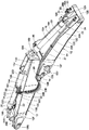
まず、図1ないし図8は本発明の第1の実施の形態を示している。図1において、1はクローラ式の油圧ショベルで、該油圧ショベル1は、自走可能な下部走行体2と、該下部走行体2上に旋回可能に搭載され、該下部走行体2と共に車体を構成する上部旋回体3と、該上部旋回体3の前側に俯仰動可能に設けられた後述の作業装置11とにより構成されている。上部旋回体3は、旋回フレーム4上にキャブ5を有し、該キャブ5内には、運転席、各種操作レバー等(いずれも図示せず)が配設されている。さらに、上部旋回体3の後側には、油圧ポンプを駆動するエンジン等(いずれも図示せず)が搭載されている。   1 to 8 show a first embodiment of the present invention. In FIG. 1, reference numeral 1 denotes a crawler-type hydraulic excavator. The hydraulic excavator 1 is mounted on a self-propelled lower traveling body 2 and the lower traveling body 2 so as to be able to turn. The upper revolving structure 3 is configured, and a working device 11 (described later) provided on the front side of the upper revolving structure 3 so as to be able to move up and down. The upper swing body 3 has a cab 5 on a swing frame 4, and a driver's seat, various operation levers and the like (all not shown) are disposed in the cab 5. Further, an engine or the like (none of which is shown) for driving the hydraulic pump is mounted on the rear side of the upper swing body 3.

11は上部旋回体3の前側に俯仰動可能に設けられた油圧ショベル1の作業装置を示している。この作業装置11は、2ピースブーム仕様の作業装置として構成され、土砂等の掘削作業の他に、例えば、後述のバケット16を圧砕機(図示せず)に交換することによって建造物の解体作業等に用いられるものである。   Reference numeral 11 denotes a working device of the excavator 1 provided on the front side of the upper swing body 3 so as to be able to move up and down. This work device 11 is configured as a work device of a two-piece boom specification, and in addition to excavation work such as earth and sand, for example, by exchanging a bucket 16 described later with a crusher (not shown), the work of dismantling the building Etc. are used.

ここで、作業装置11は、後述の第1ブーム12、第2ブーム13、連結ピン14、アーム15、バケット16、ブームシリンダ17、ポジショニングシリンダ18、アームシリンダ19、バケットシリンダ21等により構成されている。第1ブーム12、第2ブーム13、アーム15は、作業装置11の作業腕を構成している。さらに、作業装置11には、各シリンダ17,18,19,21に対して圧油を給排するための複数本の固定管体22,23,26、落下防止弁25等に接続される複数本の可撓管体27、該各可撓管体27を取付ける(固定する)ための管体ブラケット33、Uボルト34等が設けられている。   Here, the working device 11 includes a first boom 12, a second boom 13, a connecting pin 14, an arm 15, a bucket 16, a boom cylinder 17, a positioning cylinder 18, an arm cylinder 19, a bucket cylinder 21, and the like which will be described later. Yes. The first boom 12, the second boom 13, and the arm 15 constitute a work arm of the work device 11. Further, the working device 11 includes a plurality of fixed pipe bodies 22, 23, 26 for supplying and discharging pressure oil to and from each cylinder 17, 18, 19, 21, a plurality of fall prevention valves 25, and the like. A flexible tube body 27, a tube bracket 33 for attaching (fixing) each flexible tube body 27, a U bolt 34, and the like are provided.

12は旋回フレーム4の前側に俯仰動可能に取付けられた第1ブームである。この第1ブーム12は、後述の第2ブーム13と共に2ピースブームを構成するものである。ここで、第1ブーム12は、内部が中空で横断面が四角形状のボックス構造体からなり、上面を形成する上板12A、下面を形成する下板12B、左側面を形成する左側板12C、および右側面を形成する右側板(図示せず)を外周面として有している。   A first boom 12 is attached to the front side of the revolving frame 4 so as to be able to move up and down. The first boom 12 constitutes a two-piece boom together with a second boom 13 described later. Here, the first boom 12 is formed of a box structure having a hollow inside and a rectangular cross section, and includes an upper plate 12A that forms an upper surface, a lower plate 12B that forms a lower surface, a left plate 12C that forms a left side surface, And a right side plate (not shown) forming the right side surface as an outer peripheral surface.

図2、図3に示すように、第1ブーム12のフート部となる基端部12D側には、左,右方向に延びるように連結筒12Eが設けられている。これにより、第1ブーム12の基端部12Dは、その連結筒12Eが連結ピン(図示せず)を介して旋回フレーム4の左,右の縦板に対し上,下方向ないし前,後方向に回動可能に取付けられている。   As shown in FIGS. 2 and 3, a connecting cylinder 12 </ b> E is provided on the base end portion 12 </ b> D side that is a foot portion of the first boom 12 so as to extend in the left and right directions. As a result, the base end portion 12D of the first boom 12 has an upper, lower or front, rearward direction with respect to the left and right vertical plates of the revolving frame 4 with the connecting cylinder 12E via the connecting pin (not shown). It is attached to be able to rotate.

一方、第1ブーム12の先端部12F側には、左,右方向で対面する一対の板体からなる第2ブーム取付部材12Gが設けられている。この第2ブーム取付部材12Gには、後述する第2ブーム13の基端部13D側が連結ピン14を介して回動可能にピン結合されている。   On the other hand, on the distal end portion 12F side of the first boom 12, a second boom attachment member 12G made of a pair of plates facing in the left and right directions is provided. A base end portion 13D side of a second boom 13 to be described later is pin-coupled to the second boom attachment member 12G via a connecting pin 14 so as to be rotatable.

さらに、第1ブーム12を構成する上板12Aの基端部12D側には、シリンダブラケット12Hが設けられ、該シリンダブラケット12Hには、後述するポジショニングシリンダ18のチューブ18Aのボトム側が取付けられている。左,右の側板12Cの先端側には、後述するブームシリンダ17のロッド17Bの先端が取付けられるブームシリンダ取付部12J(左側のみ図示)が設けられている。   Further, a cylinder bracket 12H is provided on the base end portion 12D side of the upper plate 12A constituting the first boom 12, and a bottom side of a tube 18A of a positioning cylinder 18 to be described later is attached to the cylinder bracket 12H. . A boom cylinder mounting portion 12J (only the left side is shown) to which a tip of a rod 17B of a boom cylinder 17 described later is attached is provided on the tip side of the left and right side plates 12C.

13は第1ブーム12の先端部12F側に回動可能に連結された第2ブームである。この第2ブーム13は、後述するポジショニングシリンダ18の伸長動作、縮小動作により、第1ブーム12に対して上,下方向ないし前,後方向に回動するものである。第2ブーム13は、前述した第1ブーム12とほぼ同様に、内部が中空で横断面が四角形状のボックス構造体からなり、上板13A、下板13B、左側板13C、および右側板(図示せず)を外周面として有している。   Reference numeral 13 denotes a second boom that is rotatably connected to the distal end portion 12F side of the first boom 12. The second boom 13 is rotated upward, downward, frontward, and rearward with respect to the first boom 12 by an extension operation and a reduction operation of a positioning cylinder 18 described later. The second boom 13 is formed of a box structure having a hollow interior and a rectangular cross section, and is similar to the first boom 12 described above, and includes an upper plate 13A, a lower plate 13B, a left plate 13C, and a right plate (see FIG. (Not shown) as an outer peripheral surface.

図4に示すように、第2ブーム13を構成する下板13Bの基端部13D寄り位置には、連結部13Eが設けられている。この連結部13Eには、第1ブーム12の第2ブーム取付部材12Gが連結ピン14を介して回動可能に取付けられている。一方、第2ブーム13の先端部13F側には、左,右方向で対面する一対の板体からなるアーム取付部材13Gが設けられている。このアーム取付部材13Gには、後述するアーム15の基端側が回動可能にピン結合されている。   As shown in FIG. 4, a connecting portion 13 </ b> E is provided at a position closer to the base end portion 13 </ b> D of the lower plate 13 </ b> B constituting the second boom 13. A second boom attachment member 12G of the first boom 12 is rotatably attached to the connecting portion 13E via a connecting pin 14. On the other hand, on the distal end portion 13F side of the second boom 13, an arm mounting member 13G made of a pair of plates facing each other in the left and right directions is provided. A base end side of an arm 15 described later is pin-coupled to the arm mounting member 13G so as to be rotatable.

さらに、第2ブーム13の基端部13Dには、シリンダブラケット13Hが設けられ、該シリンダブラケット13Hには、後述するポジショニングシリンダ18のロッド18Bの先端側が取付けられている。第2ブーム13の上板13Aの基端部13D側には、シリンダブラケット13Jが設けられ、該シリンダブラケット13Jには、後述するアームシリンダ19のチューブ19Aのボトム側が取付けられている。   Further, a cylinder bracket 13H is provided at the base end portion 13D of the second boom 13, and a distal end side of a rod 18B of a positioning cylinder 18 described later is attached to the cylinder bracket 13H. A cylinder bracket 13J is provided on the base end 13D side of the upper plate 13A of the second boom 13, and a bottom side of a tube 19A of an arm cylinder 19 described later is attached to the cylinder bracket 13J.

15は第2ブーム13の先端側に回動可能に連結されたアーム(図1参照)である。このアーム15は、前述した第1ブーム12、第2ブーム13とほぼ同様に、内部が中空で横断面が四角形状のボックス構造体からなっている。アーム15の基端側には、後述のアームシリンダ19のロッド19Bが取付けられるシリンダブラケット15Aが設けられ、アーム15の基端側上面には、後述のバケットシリンダ21のチューブ21Aが取付けられるシリンダブラケット15Bが設けられている。   Reference numeral 15 denotes an arm (see FIG. 1) that is rotatably connected to the distal end side of the second boom 13. The arm 15 is formed of a box structure having a hollow interior and a rectangular cross section, similar to the first boom 12 and the second boom 13 described above. A cylinder bracket 15A to which a rod 19B of an arm cylinder 19 to be described later is attached is provided on the proximal end side of the arm 15, and a cylinder bracket to which a tube 21A of a bucket cylinder 21 to be described later is attached to an upper surface on the proximal end side of the arm 15. 15B is provided.

16はアーム15の先端部に回動可能に取付けられた作業具としてのバケットで、該バケット16は、土砂の掘削作業等に用いられるものである。バケット16は、リンク機構16Aがバケットシリンダ21のロッド21B先端に連結されている。ここで、バケット16は、建造物の解体作業等を行う場合には、圧砕機(図示せず)や他の作業具に交換することができる。   Reference numeral 16 denotes a bucket as a working tool rotatably attached to the tip of the arm 15, and the bucket 16 is used for excavating earth and sand. In the bucket 16, the link mechanism 16 </ b> A is connected to the tip of the rod 21 </ b> B of the bucket cylinder 21. Here, the bucket 16 can be replaced with a crusher (not shown) or another work tool when performing a dismantling operation of a building or the like.

17は旋回フレーム4と第1ブーム12との間に設けられたブームシリンダ(左側のみ図示)で、該ブームシリンダ17は、第1ブーム12を挟んで左,右に配置されている。ブームシリンダ17は、旋回フレーム4に対して第1ブーム12を俯仰動させるものである。ブームシリンダ17は、チューブ17Aのボトム側(基端側)が旋回フレーム4に回動可能に取付けられ、ロッド17Bの先端側が第1ブーム12のブームシリンダ取付部12Jに回動可能に取付けられている。   Reference numeral 17 denotes a boom cylinder (only the left side is shown) provided between the revolving frame 4 and the first boom 12, and the boom cylinder 17 is arranged on the left and right with the first boom 12 in between. The boom cylinder 17 moves the first boom 12 up and down with respect to the revolving frame 4. The boom cylinder 17 has a bottom side (base end side) of the tube 17A attached to the revolving frame 4 so as to be rotatable, and a distal end side of the rod 17B is attached to the boom cylinder attaching portion 12J of the first boom 12 so as to be rotatable. Yes.

18は第1ブーム12と第2ブーム13との間に設けられたポジショニングシリンダで、該ポジショニングシリンダ18は、第1ブーム12と第2ブーム13との開き角度を設定するものである。ここで、ポジショニングシリンダ18は、チューブ18Aのボトム側(基端側)が第1ブーム12のシリンダブラケット12Hに回動可能に取付けられ、ロッド18Bの先端側が第2ブーム13のシリンダブラケット13Hに回動可能に取付けられている。   Reference numeral 18 denotes a positioning cylinder provided between the first boom 12 and the second boom 13, and the positioning cylinder 18 sets an opening angle between the first boom 12 and the second boom 13. Here, in the positioning cylinder 18, the bottom side (base end side) of the tube 18A is rotatably attached to the cylinder bracket 12H of the first boom 12, and the distal end side of the rod 18B is rotated to the cylinder bracket 13H of the second boom 13. It is mounted movably.

ポジショニングシリンダ18は、ロッド18Bの伸縮量(突出長さ寸法)に応じて、連結ピン14を中心とした第1ブーム12と第2ブーム13との角度、即ち、第1ブーム12と第2ブーム13との開き角度(折れ角度)を適宜に設定するものである。   The positioning cylinder 18 has an angle between the first boom 12 and the second boom 13 around the connecting pin 14, that is, the first boom 12 and the second boom, according to the expansion / contraction amount (projection length dimension) of the rod 18B. 13 is set as appropriate.

19は第2ブーム13の上板13A上に位置して該第2ブーム13とアーム15との間に設けられたアームシリンダである。このアームシリンダ19は、第2ブーム13に対してアーム15を回動するものである。アームシリンダ19は、チューブ19Aの基端側が第2ブーム13のシリンダブラケット13Jに回動可能に取付けられ、ロッド19Bの先端側がアーム15のシリンダブラケット15Aに回動可能に取付けられている。   Reference numeral 19 denotes an arm cylinder located on the upper plate 13A of the second boom 13 and provided between the second boom 13 and the arm 15. The arm cylinder 19 rotates the arm 15 with respect to the second boom 13. The arm cylinder 19 has a proximal end side of the tube 19 </ b> A attached to the cylinder bracket 13 </ b> J of the second boom 13 so as to be rotatable, and a distal end side of the rod 19 </ b> B attached to the cylinder bracket 15 </ b> A of the arm 15.

ここで、アームシリンダ19には、チューブ19Aの長さ方向の中間部に位置して管体支持部材19Cが設けられている。この管体支持部材19Cは、例えば、チューブ19Aの外周から第2ブーム13の上板13Aを越える位置まで左側に延びた板状体、棒状体等により形成されている。管体支持部材19Cの先端側には、後述する管体固定具20が取付けられ、該管体固定具20を介して第1の固定管体22,23の先端側油圧配管22D,23Dを支持している。   Here, the arm cylinder 19 is provided with a tube support member 19C located at an intermediate portion in the length direction of the tube 19A. The tubular body support member 19C is formed of, for example, a plate-like body, a rod-like body, or the like that extends to the left from the outer periphery of the tube 19A to a position beyond the upper plate 13A of the second boom 13. A tube fixture 20 described later is attached to the distal end side of the tube support member 19C, and supports the distal end side hydraulic pipes 22D and 23D of the first fixed tube bodies 22 and 23 via the tube fixture 20. doing.

20はアームシリンダ19の管体支持部材19Cに設けられた管体固定具で、該管体固定具20は、管体支持部材19Cの先端側に第1の固定管体22,23の先端側油圧配管22D,23Dを固定するものである。図5、図6に示すように、管体固定具20は、管体支持部材19C側に位置して2本の短尺直管部位22D1,23D1の下半分を保持するようにW字状に形成された下受部20Aと、該下受部20Aと対向して位置し、2本の短尺直管部位22D1,23D1の上半分を保持するようにM字状に形成された上受部20Bと、前記下受部20Aと上受部20Bとの間に各短尺直管部位22D1,23D1を挟んだ状態で管体支持部材19Cに固定するボルト20Cとにより構成されている。これにより、管体固定具20は、下受部20Aと上受部20Bとの間に2本の短尺直管部位22D1,23D1を挟んで固定することができ、各先端側油圧配管22D,23Dをアームシリンダ19の側方に位置決め状態で配置することができる。   Reference numeral 20 denotes a tube fixture provided on the tube support member 19C of the arm cylinder 19, and the tube fixture 20 is connected to the tip side of the first fixed tubes 22 and 23 on the tip side of the tube support member 19C. The hydraulic pipes 22D and 23D are fixed. As shown in FIGS. 5 and 6, the tube fixture 20 is formed in a W shape so as to hold the lower half of two short straight tube portions 22D1 and 23D1 located on the tube support member 19C side. A lower receiving portion 20A, and an upper receiving portion 20B which is located facing the lower receiving portion 20A and is formed in an M shape so as to hold the upper half of the two short straight tube portions 22D1 and 23D1. The bolt 20C is fixed to the tube support member 19C with the short straight tube portions 22D1 and 23D1 sandwiched between the lower receiving portion 20A and the upper receiving portion 20B. As a result, the tube fixing tool 20 can be fixed by sandwiching the two short straight tube portions 22D1, 23D1 between the lower receiving portion 20A and the upper receiving portion 20B, and the respective distal end side hydraulic pipes 22D, 23D. Can be arranged in a positioning state on the side of the arm cylinder 19.

21はアーム15の上面側に位置して該アーム15とバケット16との間に設けられたバケットシリンダである。このバケットシリンダ21は、バケット16をアーム15の先端で回動するものである。バケットシリンダ21は、チューブ21Aの基端側がアーム15のシリンダブラケット15Bに回動可能に取付けられ、ロッド21Bの先端部がバケット16のリンク機構16Aに回動可能に取付けられている。   A bucket cylinder 21 is provided between the arm 15 and the bucket 16 and is located on the upper surface side of the arm 15. The bucket cylinder 21 rotates the bucket 16 at the tip of the arm 15. In the bucket cylinder 21, the proximal end side of the tube 21 </ b> A is rotatably attached to the cylinder bracket 15 </ b> B of the arm 15, and the distal end portion of the rod 21 </ b> B is rotatably attached to the link mechanism 16 </ b> A of the bucket 16.

次に、アームシリンダ19、バケットシリンダ21に制御弁装置(図示せず)からの圧油(作動油)を給排する第1の固定管体22,23,26、可撓管体27の構成について説明する。   Next, the structure of the 1st fixed pipe body 22,23,26 and the flexible pipe body 27 which supplies / discharges the pressure oil (operating oil) from a control valve apparatus (not shown) to the arm cylinder 19 and the bucket cylinder 21 is demonstrated. Will be described.

図2に示す如く、22,23は作業装置11の第1ブーム12、第2ブーム13の左側に位置して該各ブーム12,13の長さ方向に沿って設けられた2本の第1の固定管体を示している。この第1の固定管体22,23は、アームシリンダ19に圧油を給排するために設けられ、例えば、金属製の鋼管からなる油圧配管22A,22D,23A,23D、可撓性を有するゴム材料、金属製編組等を含む多層構造をなした油圧ホース22B,23B等を組合せることにより圧油の管路を構成している。   As shown in FIG. 2, the two first and second booms 22, 23 are located on the left side of the first boom 12 and the second boom 13 of the work device 11 and are provided along the length direction of the booms 12, 13. The fixed tube body is shown. The first fixed pipes 22 and 23 are provided to supply and discharge the pressure oil to and from the arm cylinder 19. For example, the hydraulic pipes 22 </ b> A, 22 </ b> D, 23 </ b> A and 23 </ b> D made of metal steel pipes have flexibility. A pressure oil conduit is formed by combining hydraulic hoses 22B and 23B having a multilayer structure including a rubber material, a metal braid, and the like.

まず、第1の固定管体22,23のうち、左,右方向の外側に位置してアームシリンダ19を縮小させるときに圧油が供給される第1の固定管体22(縮み側)について述べる。この第1の固定管体22は、第1ブーム12の上板12A上に位置して基端部12Dから先端側の第2ブーム取付部材12Gまで延びた基端側油圧配管22Aと、該基端側油圧配管22Aの先端に接続された油圧ホース22Bと、該油圧ホース22Bの先端に接続された管継手22Cと、該管継手22Cに接続された先端側油圧配管22Dとにより構成されている。   First, of the first fixed tube bodies 22 and 23, the first fixed tube body 22 (on the contraction side) to which pressure oil is supplied when the arm cylinder 19 is contracted by being positioned outside in the left and right directions. State. The first fixed pipe body 22 is located on the upper plate 12A of the first boom 12 and extends from the base end portion 12D to the second boom mounting member 12G on the front end side, and the base end side hydraulic piping 22A. The hydraulic hose 22B is connected to the tip of the end-side hydraulic pipe 22A, the pipe joint 22C is connected to the tip of the hydraulic hose 22B, and the tip-side hydraulic pipe 22D is connected to the pipe joint 22C. .

ここで、基端側油圧配管22Aは、その先端部を下側(連結ピン14側)に屈曲させることにより、この屈曲部位に接続される油圧ホース22Bに、第1ブーム12に対する第2ブーム13の回動を許すための好ましい弛み形状(円弧)を与えている。基端側油圧配管22Aは、後述する第1の固定管体23(伸び側)の基端側油圧配管23Aと平行に並んだ状態で、第1ブーム12の長さ方向の複数個所、例えば3箇所にクランプ部材24を用いて固定されている。   Here, the base end side hydraulic pipe 22A bends its distal end downward (on the connecting pin 14 side), so that the hydraulic hose 22B connected to the bent portion is connected to the second boom 13 with respect to the first boom 12. A preferable slack shape (circular arc) for allowing the rotation of the lens is provided. The base end side hydraulic pipe 22A is arranged in parallel with a base end side hydraulic pipe 23A of a first fixed pipe body 23 (extended side) to be described later. The clamp member 24 is used for fixing at the location.

一方、先端側油圧配管22Dは、アームシリンダ19のチューブ19Aに沿って直線状に延びた短尺直管部位22D1と、該短尺直管部位22D1の後端から半円弧状に湾曲した曲管部位22D2と、該曲管部位22D2からチューブ19Aに沿って先端側(ロッド19Bの伸び方向)に直線状に延びた長尺直管部位22D3とによりJ字状に形成されている。先端側油圧配管22Dは、その短尺直管部位22D1が管体固定具20を介してアームシリンダ19の管体支持部材19Cに固定されている。一方、先端側油圧配管22Dの長尺直管部位22D3は、チューブ19Aの先端側に設けられた縮み側の油圧ポート(図示せず)に落下防止弁25を介して接続されている。   On the other hand, the front end side hydraulic pipe 22D includes a short straight pipe portion 22D1 extending linearly along the tube 19A of the arm cylinder 19 and a curved pipe portion 22D2 curved in a semicircular arc shape from the rear end of the short straight pipe portion 22D1. And a long straight tube portion 22D3 linearly extending from the bent tube portion 22D2 along the tube 19A to the distal end side (extending direction of the rod 19B). The distal-side hydraulic pipe 22D has a short straight pipe portion 22D1 fixed to the pipe support member 19C of the arm cylinder 19 through the pipe fixture 20. On the other hand, the long straight pipe portion 22D3 of the distal end side hydraulic piping 22D is connected via a fall prevention valve 25 to a contraction side hydraulic port (not shown) provided on the distal end side of the tube 19A.

さらに、管継手22Cは、エルボと呼ばれるもので、圧油の流通方向をほぼ直角に変更することができる。第1の固定管体22では、この管継手22Cを油圧ホース22Bと先端側油圧配管22Dとの間に設けることにより、油圧ホース22Bによって下側から上側に向けて供給される圧油の供給方向を後側(先端側油圧配管22D側)に変更している。   Furthermore, the pipe joint 22 </ b> C is called an elbow, and can change the flow direction of the pressure oil to a substantially right angle. In the first fixed pipe body 22, by providing this pipe joint 22C between the hydraulic hose 22B and the tip side hydraulic pipe 22D, the supply direction of the pressure oil supplied from the lower side to the upper side by the hydraulic hose 22B. Is changed to the rear side (front end side hydraulic piping 22D side).

次に、アームシリンダ19の伸び側となる第1の固定管体23について述べる。この第1の固定管体23は、前述した第1の固定管体22とほぼ同様に、基端側油圧配管23A、油圧ホース23B、管継手23C、先端側油圧配管23Dにより構成されている。基端側油圧配管23Aは、基端側油圧配管22Aと平行に並んだ状態で、第1ブーム12の長さ方向の3箇所にクランプ部材24を用いて固定されている。   Next, the first fixed tube body 23 on the extension side of the arm cylinder 19 will be described. The first fixed pipe body 23 is configured by a base end side hydraulic pipe 23A, a hydraulic hose 23B, a pipe joint 23C, and a front end side hydraulic pipe 23D in substantially the same manner as the first fixed pipe body 22 described above. The base end side hydraulic pipe 23A is fixed by using clamp members 24 at three positions in the length direction of the first boom 12 in a state of being arranged in parallel with the base end side hydraulic pipe 22A.

一方、先端側油圧配管23Dは、アームシリンダ19のチューブ19Aに沿って直線状に延びた短尺直管部位23D1と、該短尺直管部位22D1の後端から左,右方向の右側に延びた曲管部位23D2と、該曲管部位23D2からチューブ19Aに沿って後側(ボトム側)に直線状に延びた長尺直管部位23D3とによりクランク状に形成されている。先端側油圧配管23Dは、その短尺直管部位23D1が短尺直管部位22D1と一緒に管体固定具20を介してアームシリンダ19の管体支持部材19Cに固定されている。長尺直管部位23D3は、チューブ19Aの基端側に設けられた伸び側の油圧ポート(図示せず)に接続されている。   On the other hand, the distal end side hydraulic pipe 23D has a short straight pipe portion 23D1 extending linearly along the tube 19A of the arm cylinder 19, and a curve extending from the rear end of the short straight pipe portion 22D1 to the left and to the right in the right direction. It is formed in a crank shape by a tube portion 23D2 and a long straight tube portion 23D3 extending linearly from the bent tube portion 23D2 to the rear side (bottom side) along the tube 19A. The distal-side hydraulic pipe 23D has a short straight pipe portion 23D1 fixed together with the short straight pipe portion 22D1 to the pipe support member 19C of the arm cylinder 19 through the pipe fixture 20. The long straight pipe portion 23D3 is connected to an extension-side hydraulic port (not shown) provided on the proximal end side of the tube 19A.

さらに、管継手23Cは、前述した管継手22Cと同様に、油圧ホース23Bによって下側から上側に向けて供給される圧油の供給方向を後側(先端側油圧配管23D側)に変更している。   Furthermore, the pipe joint 23C changes the supply direction of the pressure oil supplied from the lower side to the upper side by the hydraulic hose 23B to the rear side (the front end side hydraulic pipe 23D side) in the same manner as the pipe joint 22C described above. Yes.

25はアームシリンダ19のチューブ19Aの先端側に設けられた落下防止弁である。この落下防止弁25は、チューブ19Aの縮み側の油圧ポートと第1の固定管体22との間に配置されている。落下防止弁25は、アームシリンダ19に圧油を給排する第1の固定管体22,23が損傷した場合に、アームシリンダ19のロッド19Bが伸長してアーム15が下側に回動しないように、アームシリンダ19を油圧ロック状態にするものである。落下防止弁25には、後述する可撓管体27が接続されている。さらに、落下防止弁25は、前述したポジショニングシリンダ18等にも取付けられている。   Reference numeral 25 denotes a fall prevention valve provided on the distal end side of the tube 19 </ b> A of the arm cylinder 19. The fall prevention valve 25 is disposed between the hydraulic port on the contraction side of the tube 19 </ b> A and the first fixed tube body 22. When the first fixed pipes 22 and 23 for supplying and discharging pressure oil to and from the arm cylinder 19 are damaged, the drop prevention valve 25 extends the rod 19B of the arm cylinder 19 so that the arm 15 does not rotate downward. Thus, the arm cylinder 19 is brought into a hydraulic lock state. A flexible tube 27 (described later) is connected to the fall prevention valve 25. Further, the fall prevention valve 25 is also attached to the above-described positioning cylinder 18 and the like.

次に、26は第1ブーム12、第2ブーム13の右側に位置して該各ブーム12,13の長さ方向に沿って設けられた2本の第2の固定管体を示している。この第2の固定管体26は、バケットシリンダ21に圧油を給排するために設けられている。この第2の固定管体26は、前述した第1の固定管体22,23とほぼ同様に、基端側油圧配管26A、中間油圧ホース、管継手(いずれも図示せず)、先端側油圧配管26B、先端側油圧ホース26C(図1中に図示)により構成されている。先端側油圧ホース26Cは、バケットシリンダ21のチューブ21Aに接続されている。   Next, reference numeral 26 denotes two second fixed pipes that are provided on the right side of the first boom 12 and the second boom 13 and are provided along the length direction of the booms 12 and 13. The second fixed tube body 26 is provided for supplying and discharging pressure oil to and from the bucket cylinder 21. The second fixed pipe body 26 is similar to the first fixed pipe bodies 22 and 23 described above, and includes a proximal end side hydraulic pipe 26A, an intermediate hydraulic hose, a pipe joint (all not shown), and a distal end side hydraulic pressure. The pipe 26B and the front end side hydraulic hose 26C (shown in FIG. 1) are configured. The front end side hydraulic hose 26 </ b> C is connected to the tube 21 </ b> A of the bucket cylinder 21.

2本の基端側油圧配管26Aは、平行に並んだ状態で、第1ブーム12に対し複数個のクランプ部材24(1個のみ図示)を用いて固定されている。同様に、先端側油圧配管26Bも第2ブーム13に対し複数個のクランプ部材(図示せず)を用いて固定されている。   The two base end side hydraulic pipes 26 </ b> A are fixed to the first boom 12 using a plurality of clamp members 24 (only one is shown) in a state of being arranged in parallel. Similarly, the front end side hydraulic pipe 26 </ b> B is also fixed to the second boom 13 using a plurality of clamp members (not shown).

27は固定管体22,23,26とは別個に各ブーム12,13の長さ方向に沿って設けられた可撓管体を示している。この可撓管体27は、落下防止弁25に制御用の圧油(パイロット圧)を給排するもので、例えば3本設けられている。可撓管体27は、可撓性を有するゴム材料、金属製編組等を含む多層構造をなした油圧ホースとして形成されている。ここで、可撓管体27は、基端側油圧ホース28、連結用アダプタ29、先端側油圧ホース30からなり、長さ方向で隣合う基端側油圧ホース28の端部と先端側油圧ホース30の端部とを連結用アダプタ29を用いて連結することにより所望の長さ寸法に形成されている。   Reference numeral 27 denotes a flexible tube provided along the length direction of each boom 12, 13 separately from the fixed tubes 22, 23, 26. For example, three flexible tube bodies 27 are provided for supplying and discharging control pressure oil (pilot pressure) to the fall prevention valve 25. The flexible tube 27 is formed as a hydraulic hose having a multilayer structure including a flexible rubber material, a metal braid, and the like. Here, the flexible tubular body 27 includes a proximal end side hydraulic hose 28, a connection adapter 29, and a distal end side hydraulic hose 30, and the end portion of the proximal end side hydraulic hose 28 and the distal end side hydraulic hose adjacent in the length direction. 30 end portions are connected to each other by using a connecting adapter 29 to form a desired length.

可撓管体27の基端側油圧ホース28は、第1ブーム12の上板12A上の右側位置を基端側から先端側に延び、この先端位置で屈曲して左側に延び、上板12Aの左側で屈曲し第1の固定管体22,23の基端側油圧配管22A,23Aに沿って先端側に延びている。第1ブーム12の第2ブーム取付部材12Gよりも先に延びる基端側油圧ホース28の先端側は、第1の固定管体22,23の油圧ホース22B,23Bとほぼ同様に、第1ブーム12に対する第2ブーム13の回動を許すためにJ字状の弛み形状を形成し、この油圧ホース22B,23Bに沿って上側に延びている。基端側油圧ホース28は、基端側の端部に設けられた口金具28Aが取付ブラケット28Bを介して上板12Aに取付けられている。一方、先端側の端部に設けられた口金具28Cは連結用アダプタ29に接続されている。さらに、基端側油圧ホース28の途中部位は、結束具(図示せず)を用いて第2の固定管体26、第1の固定管体22,23に結び付けられている。   The proximal end side hydraulic hose 28 of the flexible tubular body 27 extends from the proximal end side to the distal end side at the right side position on the upper plate 12A of the first boom 12, bends at this distal end position, and extends to the left side. The first fixed pipe bodies 22 and 23 are bent at the left side of the first fixed pipe bodies 22 and 23, and extend to the distal end side along the proximal end side hydraulic pipes 22A and 23A. The distal end side of the base end side hydraulic hose 28 extending ahead of the second boom attachment member 12G of the first boom 12 is substantially the same as the hydraulic hoses 22B and 23B of the first fixed pipe bodies 22 and 23, and the first boom. In order to allow the second boom 13 to rotate with respect to 12, a J-shaped slack shape is formed and extends upward along the hydraulic hoses 22B and 23B. In the base end side hydraulic hose 28, a fitting 28A provided at the end on the base end side is attached to the upper plate 12A via a mounting bracket 28B. On the other hand, the end fitting 28 </ b> C provided at the end on the distal end side is connected to the connecting adapter 29. Further, a midway portion of the base end side hydraulic hose 28 is connected to the second fixed tube body 26 and the first fixed tube bodies 22 and 23 using a binding tool (not shown).

連結用アダプタ29は、基端側油圧ホース28と先端側油圧ホース30とを連結する継手として形成されている。図6に示すように、連結用アダプタ29は、圧油の流通方向をほぼ直角に変更するもので、直角に配置された2つの接続部29A,29Bを有している。一方の接続部29Aは、内部を圧油が流通するめねじ筒として形成され、この接続部29Aには、基端側油圧ホース28の口金具28Cが接続されている。   The connection adapter 29 is formed as a joint for connecting the proximal end side hydraulic hose 28 and the distal end side hydraulic hose 30. As shown in FIG. 6, the connecting adapter 29 changes the flow direction of the pressure oil to a substantially right angle, and has two connecting portions 29A and 29B arranged at a right angle. One connecting portion 29A is formed as a female screw cylinder through which pressure oil flows, and a fitting 28C of the base end side hydraulic hose 28 is connected to the connecting portion 29A.

他方の接続部29Bは、一方の接続部29Aよりも長尺なめねじ筒として形成され、この接続部29Bには、先端側油圧ホース30の口金具30Aが接続されている。ここで、接続部29Bは、長尺に形成することにより、後述の管体ブラケット33の管体挿通孔33Dに挿通した状態で、2個のナット31,32で縦板部33Bを挟むことにより、管体ブラケット33に取付けることができる。   The other connecting portion 29B is formed as a female thread cylinder that is longer than the one connecting portion 29A, and the end fitting hydraulic hose 30 fitting 30A is connected to the connecting portion 29B. Here, the connecting portion 29B is formed in a long shape, and the vertical plate portion 33B is sandwiched between the two nuts 31 and 32 in a state where the connecting portion 29B is inserted into a tube insertion hole 33D of the tube bracket 33 described later. The tube bracket 33 can be attached.

先端側油圧ホース30は、第1の固定管体22の先端側油圧配管22Dに沿うように、連結用アダプタ29から基端側に延びた後に、折り返して先端側に延びている。先端側油圧ホース30は、一方の口金具30Aが連結用アダプタ29の接続部29Bに接続され、他方の口金具30Bが落下防止弁25に接続されている。   The distal end side hydraulic hose 30 extends from the connection adapter 29 to the proximal end side and extends to the distal end side along the distal end side hydraulic pipe 22 </ b> D of the first fixed tube 22. The distal end hydraulic hose 30 has one end fitting 30 </ b> A connected to the connection portion 29 </ b> B of the coupling adapter 29 and the other end fitting 30 </ b> B connected to the fall prevention valve 25.

次に、3本の可撓管体27の途中部位を2本の固定管体22,23に取付けるために設けられた管体ブラケット33とUボルト34とについて説明する。   Next, a description will be given of the tube bracket 33 and the U bolt 34 that are provided to attach intermediate portions of the three flexible tube bodies 27 to the two fixed tube bodies 22 and 23.

33は2本の固定管体22,23の先端側油圧配管22D,23Dの下側に配設された管体ブラケットを示している。この管体ブラケット33は、各先端側油圧配管22D,23Dの短尺直管部位22D1,23D1よりも下側に、Uボルト34を用いて吊下げ状態で取付けられている。   Reference numeral 33 denotes a pipe bracket disposed below the tip side hydraulic pipes 22D and 23D of the two fixed pipe bodies 22 and 23. The tubular bracket 33 is attached in a suspended state using U-bolts 34 below the short straight pipe portions 22D1 and 23D1 of the distal end side hydraulic pipes 22D and 23D.

図6ないし図8に示すように、管体ブラケット33は、例えば強度をもった長方形状の金属板をL字状に折曲げることにより形成されている。即ち、管体ブラケット33は、狭幅な横板部33Aと、該横板部33Aの一方の長辺からほぼ直角に屈曲して延びた広幅な縦板部33Bとからなり、前記横板部33Aには、長さ方向に間隔をもって複数個、例えば4個のボルト挿通孔33Cが設けられている。ここで、管体ブラケット33は、横板部33Aに4個のボルト挿通孔33Cを設けたことにより、2個のUボルト34を用いて2本の固定管体22,23に取付けることができる。   As shown in FIGS. 6 to 8, the tube bracket 33 is formed, for example, by bending a strong rectangular metal plate into an L shape. That is, the tube bracket 33 is composed of a narrow horizontal plate portion 33A and a wide vertical plate portion 33B that is bent and extended substantially perpendicularly from one long side of the horizontal plate portion 33A. 33A is provided with a plurality of, for example, four bolt insertion holes 33C at intervals in the length direction. Here, the tube bracket 33 can be attached to the two fixed tube bodies 22 and 23 using the two U bolts 34 by providing the four bolt insertion holes 33C in the horizontal plate portion 33A. .

一方、縦板部33Bには、3本の可撓管体27に対応し、管体挿通孔33Dが長さ方向に間隔をもって3個設けられている。この管体挿通孔33Dは、可撓管体27を構成する連結用アダプタ29の接続部29Bが挿通されるものである。   On the other hand, in the vertical plate portion 33B, three tube insertion holes 33D corresponding to the three flexible tube bodies 27 are provided at intervals in the length direction. The tube insertion hole 33 </ b> D is for insertion of the connection portion 29 </ b> B of the connection adapter 29 constituting the flexible tube 27.

34は固定管体22,23を跨いで配置されたUボルトを示している。このUボルト34は、一般に市販されている安価なもので、管体ブラケット33に取付けられるべき固定管体22,23の本数に対応した個数、即ち、2個設けられている。Uボルト34は、先端側のおねじ部34Aを管体ブラケット33のボルト挿通孔33Cに挿通し、該各おねじ部34Aにナット35(ダブルナット)を螺着するようになっている。このときに、各Uボルト34を2本の固定管体22,23を構成する先端側油圧配管22D,23Dの短尺直管部位22D1,23D1を跨がせることにより、管体ブラケット33を前記短尺直管部位22D1,23D1に固定することができる。   Reference numeral 34 denotes a U-bolt arranged across the fixed tube bodies 22 and 23. The U bolts 34 are generally inexpensive and are commercially available, and are provided in a number corresponding to the number of the fixed tube bodies 22 and 23 to be attached to the tube bracket 33, that is, two. The U-bolt 34 is configured such that a male thread part 34A at the distal end is inserted into a bolt insertion hole 33C of the tube bracket 33, and a nut 35 (double nut) is screwed to each male thread part 34A. At this time, the U-bolts 34 are straddled over the short straight pipe portions 22D1 and 23D1 of the front end side hydraulic pipes 22D and 23D constituting the two fixed pipe bodies 22 and 23, whereby the pipe body bracket 33 is attached to the short-length pipe 33. It can be fixed to the straight pipe portions 22D1, 23D1.

しかも、Uボルト34は、管体固定具20と管継手22C,23Cとの間に位置して短尺直管部位22D1,23D1に配置しているから、ナット35が緩むようなことがあっても、管体ブラケット33の位置ずれを小さく抑えることができる。   Moreover, since the U-bolt 34 is located between the tubular fixture 20 and the pipe joints 22C and 23C and is disposed in the short straight pipe portions 22D1 and 23D1, the nut 35 may be loosened. The positional deviation of the tube bracket 33 can be kept small.

次に、管体ブラケット33とUボルト34とを用いて可撓管体27を各固定管体22,23に取付ける場合の作業手順の一例を述べる。   Next, an example of an operation procedure when the flexible tube 27 is attached to the fixed tubes 22 and 23 using the tube bracket 33 and the U bolt 34 will be described.

図6に示すように、2個のUボルト34を2本の固定管体22,23を構成する先端側油圧配管22D,23Dの短尺直管部位22D1,23D1を上側から跨ぐように配置する。この状態で、管体ブラケット33を各短尺直管部位22D1,23D1に下側から近付け、横板部33Aのボルト挿通孔33CにUボルト34のおねじ部34Aを挿通させ、該各おねじ部34Aにナット35を螺着することにより、図5、図7に示すように、横板部33Aを各短尺直管部位22D1,23D1に押付けた状態で固定管体22,23に管体ブラケット33を固定することができる。   As shown in FIG. 6, two U bolts 34 are arranged so as to straddle the short straight pipe portions 22D1 and 23D1 of the distal end side hydraulic pipes 22D and 23D constituting the two fixed pipe bodies 22 and 23 from above. In this state, the tubular bracket 33 is brought close to the short straight pipe portions 22D1 and 23D1 from the lower side, and the male screw portion 34A of the U bolt 34 is inserted into the bolt insertion hole 33C of the horizontal plate portion 33A. By screwing the nut 35 to 34A, as shown in FIGS. 5 and 7, the tubular bracket 33 is fixed to the fixed tubular bodies 22 and 23 in a state where the horizontal plate portion 33A is pressed against the respective short straight pipe portions 22D1 and 23D1. Can be fixed.

一方、可撓管体27を管体ブラケット33に取付ける場合には、図6に示すように、可撓管体27を構成する連結用アダプタ29の接続部29Bに1個のナット31を螺合させ、この接続部29Bを管体ブラケット33の管体挿通孔33Dに挿通させる。この状態で、接続部29Bにナット32を螺着することにより、各ナット31,32で縦板部33Bを挟んで連結用アダプタ29を管体ブラケット33に取付けることができる。これにより、各可撓管体27を管体ブラケット33を介して固定管体22,23に取付けることができる。   On the other hand, when the flexible tube 27 is attached to the tube bracket 33, as shown in FIG. 6, one nut 31 is screwed into the connection portion 29 </ b> B of the connecting adapter 29 constituting the flexible tube 27. The connecting portion 29B is inserted into the tube insertion hole 33D of the tube bracket 33. In this state, the connecting adapter 29 can be attached to the tube bracket 33 by screwing the nut 32 into the connecting portion 29B, with the nuts 31 and 32 sandwiching the vertical plate portion 33B. Thereby, each flexible tube 27 can be attached to the fixed tubes 22 and 23 via the tube bracket 33.

なお、上述した作業手順の他に、例えば、各可撓管体27を管体ブラケット33に取付けた後に、各可撓管体27が取付けられた管体ブラケット33を固定管体22,23に取付ける構成としてもよい。   In addition to the above-described work procedure, for example, after each flexible tube 27 is attached to the tube bracket 33, the tube bracket 33 to which each flexible tube 27 is attached is attached to the fixed tube 22, 23. It is good also as a structure to attach.

第1の実施の形態に適用される油圧ショベル1は、上述の如き構成を有するもので、次に、その動作について説明する。   The hydraulic excavator 1 applied to the first embodiment has the above-described configuration, and the operation thereof will be described next.

まず、オペレータは、キャブ5に搭乗し各種の操作レバー、ペダル等(いずれも図示せず)のうち、走行用の操作レバー、ペダルを操作することにより、下部走行体2を走行させることができる。さらに、オペレータは、作業用の操作レバーを操作することにより、作業装置11の第1ブーム12、第2ブーム13、アーム15、バケット16を動作させ、例えば土砂の掘削作業を行うことができる。   First, the operator can travel the lower traveling body 2 by boarding the cab 5 and operating the operating lever and pedal for traveling among various operating levers and pedals (all not shown). . Further, the operator can operate the first boom 12, the second boom 13, the arm 15, and the bucket 16 of the work device 11 by operating the operation lever, and can perform, for example, excavation work of earth and sand.

ここで、土砂の掘削作業時には、飛石等が発生し、作業装置11に衝突する。この場合、管体ブラケット33は、固定管体22,23よりも下側に吊下げ状態で取付けているから、管体ブラケット33に取付けられた可撓管体27は、固定管体22,23によって覆うことができ、可撓管体27を飛石等から保護することができる。   Here, during the excavation work of earth and sand, stepping stones and the like are generated and collide with the work device 11. In this case, since the tubular bracket 33 is attached in a suspended state below the fixed tubular bodies 22 and 23, the flexible tubular body 27 attached to the tubular bracket 33 is fixed to the fixed tubular bodies 22 and 23. The flexible tubular body 27 can be protected from flying stones or the like.

かくして、本実施の形態によれば、Uボルト34のおねじ部34Aが挿通されるボルト挿通孔33Cと可撓管体27を構成する連結用アダプタ29の接続部29Bが挿通される管体挿通孔33Dとを有する管体ブラケット33と、第1の固定管体22,23を構成する先端側油圧配管22D,23Dの短尺直管部位22D1,23D1を跨いで配置され、前記管体ブラケット33のボルト挿通孔33Cに挿通されて前記管体ブラケット33を前記短尺直管部位22D1,23D1に固定するUボルト34とを設け、前記可撓管体27は、連結用アダプタ29の接続部29Bを前記管体ブラケット33の管体挿通孔33Dに挿通することにより前記第1の固定管体22,23に取付ける構成としている。   Thus, according to the present embodiment, the tube insertion through which the bolt insertion hole 33 </ b> C through which the male thread 34 </ b> A of the U bolt 34 is inserted and the connection portion 29 </ b> B of the connecting adapter 29 constituting the flexible tube 27 are inserted. The pipe bracket 33 having the hole 33D and the short straight pipe portions 22D1 and 23D1 of the distal end side hydraulic pipes 22D and 23D constituting the first fixed pipe bodies 22 and 23 are disposed across the pipe bracket 33. A U-bolt 34 that is inserted into the bolt insertion hole 33C and fixes the tube bracket 33 to the short straight tube portions 22D1 and 23D1 is provided, and the flexible tube 27 connects the connection portion 29B of the connection adapter 29 to the connection portion 29B. It is configured to be attached to the first fixed tubular bodies 22 and 23 by being inserted into the tubular body insertion hole 33D of the tubular body bracket 33.

従って、第1の固定管体22,23(短尺直管部位22D1,23D1)を跨いで配置した市販のUボルト34を、管体ブラケット33のボルト挿通孔33Cに挿通してナット35を螺着することにより、このUボルト34を用いて管体ブラケット33を第1の固定管体22,23に取付けることができる。この状態で、可撓管体27を管体ブラケット33の管体挿通孔33Dに挿通することにより、可撓管体27を前記固定管体22,23に対して取付けることができる。   Therefore, a commercially available U-bolt 34 arranged across the first fixed tube bodies 22 and 23 (short straight tube portions 22D1 and 23D1) is inserted into the bolt insertion hole 33C of the tube bracket 33 and the nut 35 is screwed. As a result, the U-bolt 34 can be used to attach the tube bracket 33 to the first fixed tubes 22 and 23. In this state, the flexible tubular body 27 can be attached to the fixed tubular bodies 22 and 23 by inserting the flexible tubular body 27 into the tubular body insertion hole 33 </ b> D of the tubular body bracket 33.

このように、可撓管体27は、特殊な部品や追加の加工を施すことなく、安価な市販のUボルト34を用いて第1の固定管体22,23に取付けることができる。しかも、管体ブラケット33を取付けているのは、第1の固定管体22,23であるから、この固定管体22,23の全長に亘って取付位置を自由に設定することができ、可撓管体27を適切な位置で固定することができる。さらに、可撓管体27のレイアウト(取回し)に対しても自由に対応することができる。   As described above, the flexible tube 27 can be attached to the first fixed tubes 22 and 23 by using an inexpensive commercially available U-bolt 34 without performing special parts or additional processing. Moreover, since the pipe brackets 33 are attached to the first fixed pipes 22 and 23, the attachment position can be freely set over the entire length of the fixed pipes 22 and 23. The flexible tube body 27 can be fixed at an appropriate position. Furthermore, it is possible to freely deal with the layout (handling) of the flexible tubular body 27.

この結果、可撓管体27を固定するときの作業性を向上でき、コストも低減することができる。しかも、Uボルト34は、それ自体が固定具をなしているから、部品点数を削減でき、全体をコンパクトに形成することができる。一方、可撓管体27を適切な位置で固定することにより、無理な位置での固定による可撓管体27の損傷を防止でき、耐久性を高めることができる。さらに、可撓管体27を無駄の無い理想的なレイアウトで配置することができる。   As a result, workability when fixing the flexible tube 27 can be improved, and the cost can be reduced. Moreover, since the U-bolt 34 itself forms a fixture, the number of parts can be reduced, and the whole can be made compact. On the other hand, by fixing the flexible tube body 27 at an appropriate position, it is possible to prevent damage to the flexible tube body 27 due to the fixation at an unreasonable position and to improve durability. Furthermore, the flexible tubular body 27 can be arranged in an ideal layout without waste.

可撓管体27は、基端側油圧ホース28と先端側油圧ホース30とを繋ぐ連結用アダプタ29の位置で管体ブラケット33に取付ける構成としている。従って、既存の連結用アダプタ29に設けられたねじ構造(接続部29B)を利用して管体ブラケット33に対し簡単に取付けることができる。   The flexible tubular body 27 is configured to be attached to the tubular body bracket 33 at a position of a connection adapter 29 that connects the proximal end side hydraulic hose 28 and the distal end side hydraulic hose 30. Therefore, it can be easily attached to the tube bracket 33 using the screw structure (connection portion 29B) provided in the existing connection adapter 29.

一方、Uボルト34は、管体ブラケット33に取付けられるべき固定管体22,23の本数に対応した個数、即ち、2個設けられている。これにより、管体ブラケット33は、2個のUボルト34によって管体ブラケット33を第1の固定管体22,23に対し、水平状態を保持した状態で強固に取付けることができる。   On the other hand, the U bolt 34 is provided in a number corresponding to the number of the fixed tube bodies 22 and 23 to be attached to the tube bracket 33, that is, two. As a result, the tubular bracket 33 can be firmly attached to the first fixed tubular bodies 22 and 23 with the two U bolts 34 while maintaining the horizontal state.

さらに、管体ブラケット33は、第1の固定管体22,23を構成する先端側油圧配管22D,23Dの短尺直管部位22D1,23D1よりも下側に吊下げ状態で取付けているから、固定管体22,23を基準にして可撓管体27を容易に取回すことができる。しかも、可撓管体27は、短尺直管部位22D1,23D1によって覆うことができ、可撓管体27を飛石等から保護することができる。   Further, since the pipe bracket 33 is attached in a suspended state below the short straight pipe portions 22D1 and 23D1 of the distal end side hydraulic pipes 22D and 23D constituting the first fixed pipe bodies 22 and 23, the pipe bracket 33 is fixed. The flexible tube 27 can be easily routed with the tubes 22 and 23 as a reference. Moreover, the flexible tube 27 can be covered with the short straight tube portions 22D1 and 23D1, and the flexible tube 27 can be protected from flying stones and the like.

次に、図9および図10は本発明の第2の実施の形態を示している。本実施の形態の特徴は、直線状に延びる固定管体に対して直線状に延びる可撓管体を管体ブラケット、Uボルトを用いて取付ける構成としたことにある。なお、第2の実施の形態では、前述した第1の実施の形態と同一の構成要素に同一符号を付し、その説明を省略するものとする。   Next, FIG. 9 and FIG. 10 show a second embodiment of the present invention. A feature of the present embodiment is that a flexible tube extending linearly is attached to a fixed tube extending linearly using a tube bracket and a U bolt. In the second embodiment, the same components as those in the first embodiment described above are denoted by the same reference numerals, and description thereof is omitted.

41,42は各ブーム12,13の長さ方向に沿って設けられた第2の実施の形態による第1の固定管体である。この第1の固定管体41,42は、第1の実施の形態による第1の固定管体22,23とほぼ同様に、基端側油圧配管41A,42A、油圧ホース41B,42B、管継手41C,42C、先端側油圧配管41D,42Dにより構成されている。   41 and 42 are the 1st fixed pipe | tube bodies by 2nd Embodiment provided along the length direction of each boom 12 and 13. FIG. The first fixed pipes 41 and 42 are substantially the same as the first fixed pipes 22 and 23 according to the first embodiment, and the proximal end side hydraulic pipes 41A and 42A, the hydraulic hoses 41B and 42B, the pipe joints 41C and 42C and front end side hydraulic piping 41D and 42D.

しかし、第2の実施の形態による基端側油圧配管41A,42Aは、第1ブーム12の上板12Aに対する高さ位置が第1の実施の形態による基端側油圧配管22A,23Aに比較して高くなるように設定されている点で、第1の実施の形態による第1の固定管体22,23と相違している。具体的には、基端側油圧配管41A,42Aは、第1ブーム12の上板12A、第2ブーム取付部材12Gとの間に、後述する可撓管体43と管体ブラケット48とを収めることができる高さ位置に配置されている。   However, the base end side hydraulic pipes 41A and 42A according to the second embodiment are higher in height position with respect to the upper plate 12A of the first boom 12 than the base end side hydraulic pipes 22A and 23A according to the first embodiment. This is different from the first fixed tube bodies 22 and 23 according to the first embodiment in that they are set to be higher. Specifically, the base end side hydraulic pipes 41A and 42A accommodate a flexible tube 43 and a tube bracket 48, which will be described later, between the upper plate 12A of the first boom 12 and the second boom attachment member 12G. It is arranged at a height position where it can.

43は固定管体41,42とは別個に各ブーム12,13の長さ方向に沿って設けられた第2の実施の形態による可撓管体を示している。この可撓管体43は、第1の実施の形態による可撓管体27とほぼ同様に、基端側油圧ホース44、連結用アダプタ45、先端側油圧ホース46により形成されている。しかし、第2の実施の形態による基端側油圧ホース44は、第1ブーム12の先端側に位置して他の連結用アダプタ47が設けられている点で、第1の実施の形態による可撓管体27と相違している。   Reference numeral 43 denotes a flexible tube according to the second embodiment provided along the length direction of each boom 12, 13 separately from the fixed tubes 41, 42. The flexible tubular body 43 is formed by a proximal end side hydraulic hose 44, a connecting adapter 45, and a distal end side hydraulic hose 46 in substantially the same manner as the flexible tubular body 27 according to the first embodiment. However, the proximal-side hydraulic hose 44 according to the second embodiment is possible according to the first embodiment in that another connecting adapter 47 is provided on the distal end side of the first boom 12. It is different from the flexible tube body 27.

48は2本の固定管体41,42の基端側油圧配管41A,42Aの下側に吊下げて配設された第2の実施の形態による管体ブラケットを示している。この管体ブラケット48は、第1の実施の形態による管体ブラケット33と同様に、L字状に折曲げられた板体からなり、横板部48A、縦板部48B、ボルト挿通孔48C、管体挿通孔(図示せず)を有している。   Reference numeral 48 denotes a pipe bracket according to the second embodiment, which is suspended from the base end side hydraulic pipes 41A and 42A of the two fixed pipe bodies 41 and 42. The tube bracket 48 is formed of a plate body bent in an L shape, like the tube bracket 33 according to the first embodiment, and includes a horizontal plate portion 48A, a vertical plate portion 48B, a bolt insertion hole 48C, It has a tube insertion hole (not shown).

管体ブラケット48は、固定管体41,42の基端側油圧配管41A,42Aを跨いで配置されたUボルト34をナット35を用いて取付けることにより、固定管体41,42に取付けることができる。この状態で、縦板部48Bの管体挿通孔に可撓管体43の基端側油圧ホース44(連結用アダプタ47)を挿通して取付けることにより、該基端側油圧ホース44を固定管体41,42に取付けることができる。   The pipe bracket 48 can be attached to the fixed pipes 41 and 42 by attaching the U bolts 34 arranged across the base end side hydraulic pipes 41A and 42A of the fixed pipes 41 and 42 using the nut 35. it can. In this state, by inserting the proximal end side hydraulic hose 44 (connecting adapter 47) of the flexible tubular body 43 into the tubular body insertion hole of the vertical plate portion 48B, the proximal end side hydraulic hose 44 is fixed. It can be attached to the body 41, 42.

かくして、このように構成された第2の実施の形態においても、前述した第1の実施の形態とほぼ同様の作用効果を得ることができる。即ち、第2の実施の形態によれば、可撓管体43を管体ブラケット48の管体挿通孔に挿通することにより、可撓管体43を固定管体41,42に対して取付けることができる。   Thus, also in the second embodiment configured as described above, it is possible to obtain substantially the same operational effects as those of the first embodiment described above. That is, according to the second embodiment, the flexible tubular body 43 is attached to the fixed tubular bodies 41 and 42 by inserting the flexible tubular body 43 into the tubular body insertion hole of the tubular body bracket 48. Can do.

なお、第1の実施の形態では、管体ブラケット33の横板部33Aに4個のボルト挿通孔33Cを設け、2個のUボルト34を用いて管体ブラケット33を2本の固定管体22,23に取付けた場合を例に挙げて説明した。しかし、本発明はこれに限らず、例えば図11に示す第1の変形例のように構成してもよい。   In the first embodiment, four bolt insertion holes 33C are provided in the horizontal plate portion 33A of the tube bracket 33, and the tube bracket 33 is fixed to two fixed tubes using two U bolts 34. The case of attaching to 22 and 23 has been described as an example. However, the present invention is not limited to this. For example, the present invention may be configured as a first modification shown in FIG.

即ち、図11において、51は第1の変形例による管体ブラケットで、該管体ブラケット51は、第1の実施の形態による管体ブラケット33とほぼ同様に、横板部51A、縦板部51B、ボルト挿通孔51C、管体挿通孔51Dにより構成されている。しかし、第1の変形例による管体ブラケット51は、第1の実施の形態による管体ブラケット33よりも左,右方向に広幅に形成され、長尺な横板部51Aに6個のボルト挿通孔51Cが形成されている点で相違している。これにより、管体ブラケット51は、3本の固定管体22,23,52に対し3個のUボルト34を用いて取付けることができる。これにより、管体ブラケット51を固定管体22,23,52に強固に取付けることができる。この構成は、第2の実施の形態にも同様に適用することができる。   That is, in FIG. 11, 51 is a tube bracket according to the first modification, and the tube bracket 51 is substantially the same as the tube bracket 33 according to the first embodiment, and includes a horizontal plate portion 51A and a vertical plate portion. 51B, a bolt insertion hole 51C, and a tube insertion hole 51D. However, the tube bracket 51 according to the first modified example is formed wider in the left and right directions than the tube bracket 33 according to the first embodiment, and six bolts are inserted into the long horizontal plate portion 51A. The difference is that the hole 51C is formed. Thereby, the tube bracket 51 can be attached to the three fixed tube bodies 22, 23, 52 using the three U bolts 34. Thereby, the tubular body bracket 51 can be firmly attached to the fixed tubular bodies 22, 23, 52. This configuration can be similarly applied to the second embodiment.

第1の実施の形態では、管体ブラケット33は、固定管体22,23を構成する先端側油圧配管22D,23Dの短尺直管部位22D1,23D1よりも下側に吊下げ状態で取付けた場合を例に挙げて説明した。しかし、本発明はこれに限らず、例えば図12に示す第2の変形例のように構成してもよい。   In the first embodiment, the pipe bracket 33 is attached in a suspended state below the short straight pipe portions 22D1 and 23D1 of the distal end side hydraulic pipes 22D and 23D constituting the fixed pipe bodies 22 and 23. Was described as an example. However, the present invention is not limited to this. For example, the present invention may be configured as a second modification shown in FIG.

即ち、図12において、61は第2の変形例による管体ブラケットで、該管体ブラケット61は、第1の実施の形態による管体ブラケット33とほぼ同様に、横板部61A、縦板部61B、ボルト挿通孔61C、管体挿通孔61Dにより構成されている。しかし、第2の変形例による管体ブラケット61は、上,下位置を反転させた状態で、短尺直管部位22D1,23D1よりも上側に取付ける構成としている。この場合、管体ブラケット61に対して可撓管体27を容易に取付けることができる。この構成は、第2の実施の形態にも同様に適用することができる。   That is, in FIG. 12, reference numeral 61 denotes a tube bracket according to the second modification, and the tube bracket 61 is substantially the same as the tube bracket 33 according to the first embodiment, and includes a horizontal plate portion 61A and a vertical plate portion. 61B, a bolt insertion hole 61C, and a tube insertion hole 61D. However, the tube bracket 61 according to the second modification is configured to be attached above the short straight tube portions 22D1 and 23D1 with the upper and lower positions reversed. In this case, the flexible tube 27 can be easily attached to the tube bracket 61. This configuration can be similarly applied to the second embodiment.

第1の実施の形態では、第1の固定管体22,23は、作業腕となる第1ブーム12と、アクチュエータとなるアームシリンダ19とに取付けた場合を例に挙げて説明した。しかし、本発明はこれに限るものではなく、例えば、第1の固定管体22,23を第1ブーム12と第2ブーム13に取付ける構成としてもよい。この構成は、第2の実施の形態にも同様に適用することができる。   In the first embodiment, the case where the first fixed tube bodies 22 and 23 are attached to the first boom 12 serving as a work arm and the arm cylinder 19 serving as an actuator has been described as an example. However, the present invention is not limited to this. For example, the first fixed tube bodies 22 and 23 may be attached to the first boom 12 and the second boom 13. This configuration can be similarly applied to the second embodiment.

第1の実施の形態では、管体ブラケット33には3本の可撓管体27を取付けた場合を例示している。しかし、本発明はこれに限るものではなく、例えば、管体ブラケットには1本、2本または4本以上の可撓管体を取付ける構成としてもよい。この構成は、第2の実施の形態にも同様に適用することができる。   In the first embodiment, a case where three flexible tube bodies 27 are attached to the tube body bracket 33 is illustrated. However, the present invention is not limited to this. For example, one, two, four or more flexible tubes may be attached to the tube bracket. This configuration can be similarly applied to the second embodiment.

各実施の形態では、第1ブーム12と第2ブーム13とからなる2ピースブームを有する作業装置11に適用した場合を例示している。しかし、本発明はこれに限らず、例えば、屈曲した1本のブームを有するモノブーム式の作業装置に適用してもよい。   In each embodiment, the case where it applies to the working device 11 which has the 2 piece boom which consists of the 1st boom 12 and the 2nd boom 13 is illustrated. However, the present invention is not limited to this, and may be applied to, for example, a mono-boom working device having one bent boom.

さらに、各実施の形態では、建設機械としてクローラ式の油圧ショベル1を例に挙げて説明した。しかし、本発明はこれに限らず、例えばホイール式の油圧ショベル等の上部旋回体に作業装置を備えた他の建設機械にも適用できるものである。   Furthermore, in each embodiment, the crawler type hydraulic excavator 1 was described as an example of the construction machine. However, the present invention is not limited to this, and can be applied to other construction machines provided with a working device on an upper rotating body such as a wheel-type hydraulic excavator.

1 油圧ショベル(建設機械)
2 下部走行体(車体)
3 上部旋回体(車体)
4 旋回フレーム
11 作業装置
12 第1ブーム(作業腕)
13 第2ブーム(作業腕)
15 アーム(作業腕)
16 バケット(作業具)
17 ブームシリンダ(アクチュエータ)
18 ポジショニングシリンダ(アクチュエータ)
19 アームシリンダ(アクチュエータ)
21 バケットシリンダ(アクチュエータ)
22,23,41 第1の固定管体
26 第2の固定管体
27,43 可撓管体
28,44 基端側油圧ホース
29,45 連結用アダプタ
30,46 先端側油圧ホース
33,48,51,61 管体ブラケット
33A,48A,51A,61A 横板部
33B,48B,51B,61B 縦板部
33C,48C,51C,61C ボルト挿通孔
33D,51D,61D 管体挿通孔
34 Uボルト
35 ナット
47 他の連結用アダプタ
52 固定管体
1 Excavator (construction machine)
2 Lower traveling body (car body)
3 Upper swing body (car body)
4 Rotating frame 11 Working device 12 First boom (working arm)
13 Second boom (working arm)
15 Arm (working arm)
16 bucket (work implement)
17 Boom cylinder (actuator)
18 Positioning cylinder (actuator)
19 Arm cylinder (actuator)
21 Bucket cylinder (actuator)
22, 23, 41 First fixed tube 26 Second fixed tube 27, 43 Flexible tube 28, 44 Base end side hydraulic hose 29, 45 Connection adapter 30, 46 Front end side hydraulic hose 33, 48, 51, 61 Tube bracket 33A, 48A, 51A, 61A Horizontal plate portion 33B, 48B, 51B, 61B Vertical plate portion 33C, 48C, 51C, 61C Bolt insertion hole 33D, 51D, 61D Tube insertion hole 34 U bolt 35 Nut 47 Other connection adapters 52 Fixed tube

Claims (4)

自走可能な車体と、該車体に俯仰動可能に取付けられ作業腕をアクチュエータで動作する作業装置と、該作業装置のアクチュエータに圧油を給排するために前記作業腕の長さ方向に沿って延び前記アクチュエータ前記作業腕とのうち少なくとも一方に固定される複数本の固定管体と、該固定管体とは別個に前記作業腕の長さ方向に沿って設けられる可撓管体とを備えてなる建設機械において、
ボルトが挿通されるボルト挿通孔と可撓管体が挿通される管体挿通孔とを有する管体ブラケットと、
前記固定管体を跨いで配置され前記管体ブラケットのボルト挿通孔に挿通されて前記管体ブラケットを前記固定管体に固定するUボルトと設けられており
前記可撓管体は、前記管体ブラケットの管体挿通孔に挿通された状態で前記固定管体に取付けられる構成としたことを特徴とする建設機械。
A self-propelled vehicle body, a work device that is attached to the vehicle body so as to be able to move up and down, and that operates a work arm with an actuator, and a length of the work arm for supplying and discharging pressure oil to and from the actuator of the work device A plurality of fixed tube bodies that extend and are fixed to at least one of the actuator and the work arm, and a flexible tube body that is provided along the length direction of the work arm separately from the fixed tube body. In a construction machine comprising
A tube bracket having a bolt insertion hole through which a bolt is inserted and a tube insertion hole through which the flexible tube is inserted;
Wherein disposed across the fixed tube body and has a U-bolt is provided for fixing the tube bracket is inserted into the bolt insertion holes of the tube bracket to the fixed tube,
The flexible tube is a construction machine, characterized in that the mounted that structure to the fixed tube body in a state of being inserted into the tube insertion holes of the tubular body bracket.
前記可撓管体は、長さ方向で隣合う管体の端部を連結用アダプタを用いて連結することにより所望の長さ寸法に形成されており
前記可撓管体は、前記連結用アダプタの位置で前記管体ブラケットに取付ける構成としてなる請求項1に記載の建設機械。
The flexible tubular body is formed in a desired length dimension by connecting the ends of adjacent tubular bodies in the length direction using a connecting adapter,
The construction machine according to claim 1, wherein the flexible tube is configured to be attached to the tube bracket at a position of the connection adapter.
前記Uボルトは、前記管体ブラケットに取付けられるべき前記固定管体の本数に対応した個数を設ける構成としてなる請求項1または2に記載の建設機械。   3. The construction machine according to claim 1, wherein the U bolt is configured to provide a number corresponding to the number of the fixed pipes to be attached to the pipe bracket. 前記固定管体は、前記作業腕の長さ方向に沿って配置されており、前記可撓管体は、前記固定管体よりも下側に配置され前記管体ブラケットにより前記固定管体に対して吊下げられた状態で取付けられる構成としてなる請求項1,2または3に記載の建設機械。 The fixed tube body is disposed along the length direction of the working arm, and the flexible tube body is disposed below the fixed tube body, and the tube bracket is attached to the fixed tube body. construction machine according to claim 1, 2 or 3 comprising a structure that is attached by hanging was state Te.
JP2013224164A 2013-10-29 2013-10-29 Construction machinery Active JP6124180B2 (en)

Priority Applications (1)

Application Number Priority Date Filing Date Title
JP2013224164A JP6124180B2 (en) 2013-10-29 2013-10-29 Construction machinery

Applications Claiming Priority (1)

Application Number Priority Date Filing Date Title
JP2013224164A JP6124180B2 (en) 2013-10-29 2013-10-29 Construction machinery

Publications (3)

Publication Number Publication Date
JP2015086540A JP2015086540A (en) 2015-05-07
JP2015086540A5 JP2015086540A5 (en) 2016-06-23
JP6124180B2 true JP6124180B2 (en) 2017-05-10

Family

ID=53049636

Family Applications (1)

Application Number Title Priority Date Filing Date
JP2013224164A Active JP6124180B2 (en) 2013-10-29 2013-10-29 Construction machinery

Country Status (1)

Country Link
JP (1) JP6124180B2 (en)

Families Citing this family (2)

* Cited by examiner, † Cited by third party
Publication number Priority date Publication date Assignee Title
JP7344844B2 (en) 2020-06-15 2023-09-14 日立建機株式会社 construction machinery
JP7305597B2 (en) * 2020-06-15 2023-07-10 株式会社クボタ Hydraulic hose relay structure and work machine

Family Cites Families (7)

* Cited by examiner, † Cited by third party
Publication number Priority date Publication date Assignee Title
JPS5756282U (en) * 1980-09-19 1982-04-02
JPH0565979A (en) * 1991-09-04 1993-03-19 Toyoda Gosei Co Ltd Setting structure of hose fitting
JPH09196240A (en) * 1996-01-22 1997-07-29 Yutani Heavy Ind Ltd Clamp device for htydraulic piping
JP2000073393A (en) * 1998-08-31 2000-03-07 Hitachi Constr Mach Co Ltd Construction machine
JP2000320521A (en) * 1999-05-13 2000-11-24 Masakatsu Miwa Pipe-mounting bolt
JP2002327453A (en) * 2001-05-07 2002-11-15 Komatsu Ltd Clamping apparatus for hydraulic pipe for working machine of construction equipment
JP5779154B2 (en) * 2012-08-15 2015-09-16 日立建機株式会社 Construction machinery

Also Published As

Publication number Publication date
JP2015086540A (en) 2015-05-07

Similar Documents

Publication Publication Date Title
JP6124180B2 (en) Construction machinery
JP4922210B2 (en) Hydraulic piping structure of excavator
JP6224565B2 (en) Construction machinery
JP6488781B2 (en) Piping joint equipment for construction machinery
JP2010163752A (en) Construction machine
JP4490751B2 (en) Outrigger hydraulic cylinder
JP6832305B2 (en) Construction machinery
JP2013237996A (en) Construction machine
JP6480233B2 (en) Working machine
KR100639729B1 (en) Working apparatus of construction machine
JP2009007760A (en) Construction machine
JP2011184920A (en) Working arm for construction machinery
JP4927882B2 (en) Two-member connecting device
JP6342355B2 (en) Working machine
JP6782262B2 (en) Short reach type hydraulic excavator
JP6868940B2 (en) Construction machinery
JP6258838B2 (en) Construction equipment front equipment
JP5253961B2 (en) Construction machinery
JP6934459B2 (en) Construction machinery
JP2931233B2 (en) Hose clamp device
JP5859996B2 (en) Construction machinery
JP5996498B2 (en) Excavator working equipment
JP4219878B2 (en) Working machine
US20160289924A1 (en) Working machine
JP5843724B2 (en) Loader working machine

Legal Events

Date Code Title Description
A521 Written amendment

Free format text: JAPANESE INTERMEDIATE CODE: A523

Effective date: 20160507

A621 Written request for application examination

Free format text: JAPANESE INTERMEDIATE CODE: A621

Effective date: 20160507

A977 Report on retrieval

Free format text: JAPANESE INTERMEDIATE CODE: A971007

Effective date: 20170127

TRDD Decision of grant or rejection written
A01 Written decision to grant a patent or to grant a registration (utility model)

Free format text: JAPANESE INTERMEDIATE CODE: A01

Effective date: 20170307

A61 First payment of annual fees (during grant procedure)

Free format text: JAPANESE INTERMEDIATE CODE: A61

Effective date: 20170324

R150 Certificate of patent or registration of utility model

Ref document number: 6124180

Country of ref document: JP

Free format text: JAPANESE INTERMEDIATE CODE: R150