JP2009007760A - Construction machine - Google Patents
Construction machine Download PDFInfo
- Publication number
- JP2009007760A JP2009007760A JP2007167703A JP2007167703A JP2009007760A JP 2009007760 A JP2009007760 A JP 2009007760A JP 2007167703 A JP2007167703 A JP 2007167703A JP 2007167703 A JP2007167703 A JP 2007167703A JP 2009007760 A JP2009007760 A JP 2009007760A
- Authority
- JP
- Japan
- Prior art keywords
- boom
- vertical pin
- hydraulic
- arm member
- hose
- Prior art date
- Legal status (The legal status is an assumption and is not a legal conclusion. Google has not performed a legal analysis and makes no representation as to the accuracy of the status listed.)
- Pending
Links
Images


Abstract
Description
本発明は、例えば土砂等の掘削作業に好適に用いられる作業装置を備えた油圧ショベル等の建設機械に関する。 The present invention relates to a construction machine such as a hydraulic excavator provided with a working device suitably used for excavating work such as earth and sand.
一般に、建設機械としての油圧ショベルは、下部走行体と上部旋回体とからなる自走可能な走行体と、該走行体の上部旋回体に俯仰動可能に設けられた作業装置とにより大略構成されている。また、油圧ショベルの作業装置としてオフセットブーム式の作業装置が知られており、このオフセットブーム式の作業装置は、オフセットシリンダ等を用いてバケット等の作業具を左,右方向に平行移動させることにより、走行体の左側または右側で側溝等の掘削作業を行うことができるものである。 2. Description of the Related Art Generally, a hydraulic excavator as a construction machine is roughly configured by a self-propelled traveling body composed of a lower traveling body and an upper revolving body, and a work device provided on the upper revolving body of the traveling body so as to be able to move up and down. ing. Also, an offset boom type working device is known as a working device for a hydraulic excavator, and this offset boom type working device translates a work tool such as a bucket in the left and right directions using an offset cylinder or the like. Thus, excavation work such as a gutter can be performed on the left side or the right side of the traveling body.
ここで、オフセットブーム式の作業装置は、通常、基端側が上部旋回体に俯仰動可能に取付けられたロアブームと、該ロアブームの先端側に左,右方向に揺動可能にピン結合されたアッパブームと、該アッパブームの先端側に左,右方向に揺動可能にピン結合されたアームステーと、ロアブームとアームステーとの間に設けられたリンクと、アームステーの先端側に俯仰動可能に取付けられたアームと、該アームの先端側に取付けられたバケットとにより大略構成されている。 Here, the offset boom type working device is generally composed of a lower boom whose base end side is attached to the upper swinging body so as to be able to move up and down, and an upper boom that is pin-coupled to the distal end side of the lower boom so as to swing left and right. And an arm stay that is pin-coupled to the left end of the upper boom so that it can swing left and right, a link provided between the lower boom and the arm stay, and an arm stay that can be moved up and down on the front end side of the arm stay And a bucket attached to the tip side of the arm.
また、オフセット式の作業装置には、ロアブームを俯仰動させるブームシリンダ、アームを俯仰動させるアームシリンダ、バケットを回動させるバケットシリンダ、アッパブームをロアブームに対して揺動させるオフセットシリンダ等の油圧アクチュエータが設けられている。そして、これら各油圧シリンダは、油圧パイプ、油圧ホース等からなる複数の油圧配管を介して、上部旋回体に設けられた油圧源に接続されている。 Further, the offset type working device includes hydraulic actuators such as a boom cylinder for raising and lowering the lower boom, an arm cylinder for raising and lowering the arm, a bucket cylinder for rotating the bucket, and an offset cylinder for swinging the upper boom with respect to the lower boom. Is provided. Each of these hydraulic cylinders is connected to a hydraulic source provided on the upper swing body through a plurality of hydraulic pipes including hydraulic pipes, hydraulic hoses and the like.
ところで、各油圧シリンダに接続される複数の油圧配管のうち、アームシリンダとバケットシリンダに圧油を給排する油圧配管は、ロアブーム、アッパブーム、アームステーに沿って配設されている。この場合、油圧配管は、金属製のパイプ材からなる油圧パイプと、可撓性を有するゴム等の材料からなる油圧ホースとにより構成され、ロアブームとアッパブームとのピン結合部の近傍部位、アッパブームとアームステーとのピン結合部の近傍部位には、通常、アッパブームやアームステーが左,右方向に揺動するのに追従して変形する油圧ホースが配設されている。 By the way, among the plurality of hydraulic pipes connected to each hydraulic cylinder, the hydraulic pipe for supplying and discharging pressure oil to and from the arm cylinder and the bucket cylinder is arranged along the lower boom, the upper boom, and the arm stay. In this case, the hydraulic piping is composed of a hydraulic pipe made of a metal pipe material and a hydraulic hose made of a material such as rubber having flexibility, a portion near the pin coupling portion between the lower boom and the upper boom, an upper boom, A hydraulic hose that deforms following the swinging of the upper boom and the arm stay in the left and right directions is usually disposed in the vicinity of the pin coupling portion with the arm stay.
しかし、この油圧ホースは、アッパブームやアームステーの揺動動作に追従するための弛みを確保するため、作業装置の外部にはみ出した状態で配設されている。このため、掘削作業時にバケット等を側溝内に没入させた場合において、油圧ホースが周囲の障害物に接触して損傷してしまう虞れがある。 However, the hydraulic hose is disposed in a state of protruding from the work device in order to ensure a slack for following the swinging motion of the upper boom and the arm stay. For this reason, when a bucket etc. is immersed in a side groove at the time of excavation work, there exists a possibility that a hydraulic hose may contact a surrounding obstacle and may be damaged.
これに対し、ロアブームとアッパブームとを連結する縦ピンと、アッパブームとアームステーとを連結する縦ピンとを円筒状に形成し、この円筒状の縦ピンの内周側にロータリジョイントを設ける構成としたオフセットブーム式の作業装置が提案されている。この作業装置によれば、縦ピンの内周側に設けたロータリジョイントの両端側に油圧パイプを接続することにより、作業装置の外部に油圧ホースがはみ出すのを防止することができる(例えば、特許文献1参照)。 On the other hand, the vertical pin for connecting the lower boom and the upper boom and the vertical pin for connecting the upper boom and the arm stay are formed in a cylindrical shape, and the rotary joint is provided on the inner peripheral side of the cylindrical vertical pin. Boom-type working devices have been proposed. According to this working device, it is possible to prevent the hydraulic hose from protruding outside the working device by connecting the hydraulic pipes to both ends of the rotary joint provided on the inner peripheral side of the vertical pin (for example, patent Reference 1).
しかし、上述した特許文献1の従来技術は、ロアブームとアッパブームとを連結する縦ピンの内周側にロータリジョイントを設ける構成としているため、縦ピンの構成が複雑化してしまい、作業装置の組立時の作業性が低下してしまう上に、製造コストの増大を招くという問題がある。
However, since the conventional technology of
本発明は上述した従来技術の問題に鑑みなされたもので、作業装置に配設される油圧配管が作業装置の外部に大きくはみ出すのを抑え、この油圧配管を保護することができるようにした建設機械を提供することを目的としている。 The present invention has been made in view of the above-described problems of the prior art, and it is possible to prevent the hydraulic piping arranged in the working device from greatly protruding outside the working device and to protect the hydraulic piping. The purpose is to provide machines.
上述した課題を解決するため、本発明は、自走可能な走行体と、該走行体に設けられ油圧アクチュエータによって作動する作業装置とを備え、前記作業装置は、第1の腕部材と、縦ピンを介して該第1の腕部材に左,右方向に回動可能に連結された第2の腕部材と、前記油圧アクチュエータに圧油を供給するために前記第1の腕部材に配設された第1の油圧配管と、前記第2の腕部材に配設された第2の油圧配管とにより構成してなる建設機械に適用される。 In order to solve the problems described above, the present invention includes a traveling body capable of self-propelling and a working device provided on the traveling body and operated by a hydraulic actuator. The working device includes a first arm member, a vertical arm, A second arm member connected to the first arm member via a pin so as to be able to rotate left and right; and a first arm member arranged to supply pressure oil to the hydraulic actuator. The present invention is applied to a construction machine constituted by the first hydraulic pipe thus constructed and the second hydraulic pipe arranged on the second arm member.
そして、請求項1の発明が採用する構成の特徴は、前記縦ピンは内周側が軸方向に貫通する中空孔となった中空ピンにより構成し、該縦ピンの中空孔内には、前記第1の油圧配管と第2の油圧配管との間を接続する接続配管を配設したことにある。
A feature of the configuration adopted by the invention of
請求項2の発明は、自走可能な走行体と、該走行体に設けられ油圧アクチュエータによって作動する作業装置とを備え、前記作業装置は、第1の腕部材と、縦ピンを介して該第1の腕部材に左,右方向に回動可能に連結された第2の腕部材と、前記油圧アクチュエータに圧油を供給するために前記第1の腕部材に配設された第1の油圧配管と、前記第2の腕部材に配設された第2の油圧配管とにより構成してなる建設機械において、前記縦ピンには軸方向に貫通する油孔を設け、該油孔の軸方向の一側には前記第1の油圧配管を接続し、前記油孔の軸方向の他側には前記第2の油圧配管を接続する構成としたことを特徴としている。
The invention of
請求項3の発明は、前記第2の腕部材は、上,下方向で対面しつつ前,後方向に延びる上板,下板と、これら上板,下板を挟んで左,右方向で対面する左側板,右側板とにより構成し、前記第2の油圧配管は、前記左,右の側板により左,右方向から覆われた状態で前記下板に沿って配置する構成としたことにある。 According to a third aspect of the present invention, the second arm member has an upper plate and a lower plate extending in the front and rear directions while facing in the upper and lower directions, and in the left and right directions across the upper and lower plates. The left side plate and the right side plate that face each other, and the second hydraulic pipe is arranged along the lower plate while being covered from the left and right sides by the left and right side plates. is there.
請求項4の発明は、前記縦ピンの油孔の軸方向一側部位と前記第1の油圧配管との接続部と、前記縦ピンの油孔の軸方向他側部位と前記第2の油圧配管との接続部とのうち、少なくとも一方の接続部には、前記油孔を中心として水平方向に回動可能なスイベル継手を設ける構成としたことにある。 According to a fourth aspect of the present invention, there is provided a connecting portion between an axial one side portion of the oil hole of the vertical pin and the first hydraulic pipe, an axial other side portion of the oil hole of the vertical pin, and the second hydraulic pressure. At least one of the connecting portions with the pipe is provided with a swivel joint that can rotate in the horizontal direction around the oil hole.
請求項5の発明は、前記作業装置は、前記走行体に取付けられブームシリンダにより上,下方向に俯仰動され前記第1の腕部材となる第1ブームと、該第1ブームの先端側に第1の縦ピンを用いて連結されオフセットシリンダにより左,右方向に回動され前記第1または第2の腕部材となる第2ブームと、該第2ブームの先端側に第2の縦ピンを用いて左,右方向に回動可能に連結された状態でリンクロッドにより前記第1ブームに対して平行に保持され前記第2の腕部材となる第3ブームとを備えたオフセットブーム式の作業装置として構成し、前記縦ピンは、前記第1,第2の縦ピンのうち少なくとも一方の縦ピンとしたことにある。 According to a fifth aspect of the present invention, the work device is attached to the traveling body and is lifted and lowered in the upward and downward directions by a boom cylinder to be the first arm member, and on the distal end side of the first boom. A second boom that is connected using a first vertical pin and is rotated left and right by an offset cylinder and serves as the first or second arm member, and a second vertical pin on the distal end side of the second boom An offset boom type comprising a third boom which is held in parallel to the first boom by a link rod and is connected to the first boom in a state of being connected to be pivotable left and right using It is configured as a working device, and the vertical pin is at least one vertical pin of the first and second vertical pins.
請求項1の発明によれば、第1の腕部材と第2の腕部材との間を中空孔を有する縦ピンによって回動可能に連結し、この縦ピンの中空孔内に配設した接続配管を介して、第1の油圧配管と第2の油圧配管との間を接続することができる。この場合、接続配管を縦ピンの中空孔内に配設することにより、第1,第2の腕部材が縦ピンを中心として相対回動したとしても、第1,第2の油圧配管が第1,第2の腕部材の回動動作に追従して大きく変形することがない。 According to the first aspect of the present invention, the first arm member and the second arm member are rotatably connected by the vertical pin having the hollow hole, and the connection disposed in the hollow hole of the vertical pin. The first hydraulic pipe and the second hydraulic pipe can be connected via the pipe. In this case, by arranging the connection pipe in the hollow hole of the vertical pin, even if the first and second arm members are relatively rotated around the vertical pin, the first and second hydraulic pipes are The first and second arm members are not greatly deformed following the rotation of the second arm member.
このため、第1,第2の油圧配管が作業装置の外部にはみ出すのを抑えることができ、これら第1,第2の油圧配管を外部の障害物等から保護することができる。また、例えば縦ピンの内部にロータリジョイントを設ける場合に比較して、縦ピンの構成を簡素化することができるので、作業装置の組立性の向上、製造コストの低減を図ることができる。 For this reason, it can suppress that the 1st, 2nd hydraulic piping protrudes outside the working apparatus, and can protect these 1st, 2nd hydraulic piping from an external obstruction. Further, for example, the configuration of the vertical pin can be simplified as compared with the case where the rotary joint is provided inside the vertical pin, so that the assembly of the working device can be improved and the manufacturing cost can be reduced.
請求項2の発明によれば、縦ピンに軸方向に貫通する油孔を形成し、該油孔の軸方向一側に第1の油圧配管を接続し、油孔の軸方向他側に第2の油圧配管を接続したので、第1の油圧配管と第2の油圧配管との間を接続する配管類を不要とすることができる。このため、第1の油圧配管と第2の油圧配管との間を別部材からなる配管類を介して接続する必要がなく、当該配管類が周囲の障害物に接触して破損することがないので、作業装置の信頼性を高めることができる。 According to the second aspect of the present invention, the oil hole penetrating in the axial direction is formed in the vertical pin, the first hydraulic pipe is connected to one axial side of the oil hole, and the first hydraulic pipe is connected to the other axial side of the oil hole. Since the two hydraulic pipes are connected, pipes for connecting the first hydraulic pipe and the second hydraulic pipe can be eliminated. For this reason, it is not necessary to connect between the 1st hydraulic piping and the 2nd hydraulic piping via piping which consists of another member, and the piping does not touch the surrounding obstacle, and is not damaged. Therefore, the reliability of the working device can be increased.
請求項3の発明によれば、第2の油圧配管を、第2の腕部材を構成する左,右の側板によって左,右方向から覆った状態で、第2の腕部材の下板に沿って配置することができる。これにより、第2の油圧配管が周囲の障害物に接触して破損するのを、第2の腕部材の左,右の側板によって防止することができ、第2の油圧配管を保護することができる。 According to the invention of claim 3, the second hydraulic pipe is along the lower plate of the second arm member in a state where the second hydraulic pipe is covered from the left and right directions by the left and right side plates constituting the second arm member. Can be arranged. Thereby, it is possible to prevent the second hydraulic piping from coming into contact with surrounding obstacles and being damaged by the left and right side plates of the second arm member, and to protect the second hydraulic piping. it can.
請求項4の発明によれば、縦ピンの油孔の軸方向一側部位と第1の油圧配管との接続部にスイベル継手を設けた場合には、縦ピンを中心として第1の腕部材と第2の腕部材とが相対回動したときにスイベル継手が油孔を中心として水平方向に回動するので、第1の油圧配管が捩じれるのを抑えることができ、該第1の油圧配管を保護することができる。一方、縦ピンの油孔の軸方向他側部位と第2の油圧配管との接続部にスイベル継手を設けた場合には、第2の油圧配管が捩じれるのをスイベル継手によって抑えることができ、該第2の油圧配管を保護することができる。
According to invention of
請求項5の発明によれば、第1ブームと第2ブームとの間を連結する第1の縦ピンと、第2ブームと第3ブームとの間を連結する第2の縦ピンのうち、少なくとも一方の縦ピンに、第1,第2の油圧配管を接続する接続配管が配設される中空孔、または第1,第2の油圧配管が接続される油孔を設けることにより、第1,第2の油圧配管がオフセットブーム式の作業装置の外部にはみ出すのを抑えることができる。
According to the invention of
以下、本発明の実施の形態による建設機械として、オフセットブーム式の作業装置を備えた油圧ショベルを例に挙げ、添付図面に従って詳細に説明する。 Hereinafter, as a construction machine according to an embodiment of the present invention, a hydraulic excavator provided with an offset boom type working device will be described as an example and described in detail with reference to the accompanying drawings.
まず、図1ないし図6は本発明の第1の実施の形態を示している。ここで、本実施の形態では、第1ブームと、該第1ブームの先端側に第1の縦ピンを介して回動可能に連結された第2ブームと、該第2ブームの先端側に第2の縦ピンを介して回動可能に連結された第3ブームとを備えたオフセットブーム式の作業装置を例に挙げ、第2ブームを第1の腕部材とし、第3ブームを第2の腕部材とした場合について説明する。 First, FIG. 1 to FIG. 6 show a first embodiment of the present invention. Here, in the present embodiment, the first boom, the second boom pivotally connected to the tip end side of the first boom via the first vertical pin, and the tip end side of the second boom An offset boom type working device having a third boom pivotably connected via a second vertical pin is taken as an example. The second boom is a first arm member, and the third boom is a second. A case where the arm member is used will be described.
そして、本実施の形態の特徴は、第1の腕部材となる第2ブームと第2の腕部材となる第3ブームとの間を連結する第2の縦ピンに、軸方向に貫通する中空孔を設け、この第2の縦ピンの中空孔内に、第1の油圧配管と第2の油圧配管とを接続する接続配管を配設する構成としたことにある。 A feature of the present embodiment is that the second vertical pin that connects the second boom that is the first arm member and the third boom that is the second arm member is a hollow that penetrates in the axial direction. A hole is provided, and a connection pipe for connecting the first hydraulic pipe and the second hydraulic pipe is disposed in the hollow hole of the second vertical pin.
図中、1は建設機械の代表例としての油圧ショベルで、該油圧ショベル1は、自走可能なクローラ式の下部走行体2と、該下部走行体2上に旋回可能に搭載され、該下部走行体2と共に走行体を構成する上部旋回体3と、該上部旋回体3の前部側に俯仰動可能に設けられた後述のオフセットブーム式の作業装置11とにより大略構成されている。
In the figure,
ここで、上部旋回体3は、下部走行体2上に旋回可能に設けられたベースとなる旋回フレーム4と、該旋回フレーム4の左前側に設けられ、運転席、各種レバー等(図示せず)が配置されたキャブ5と、該キャブ5の後方に位置して旋回フレーム4上に搭載されたエンジン、油圧ポンプ(図示せず)等の各種の搭載機器を覆う建屋カバー6と、旋回フレーム4の後端部に設けられ、後述の作業装置11との重量バランスをとるカウンタウエイト7とを含んで構成されている。
Here, the upper revolving structure 3 is provided on the lower front side of the revolving
11はキャブ5の右側方に位置して上部旋回体3の前部側に俯仰動可能に設けられたオフセットブーム式の作業装置を示し、このオフセットブーム式の作業装置11は、側溝等の掘削作業に好適に用いられるものである。ここで、作業装置11は、図2等に示すように、後述の第1ブーム12、第2ブーム13、第1の縦ピン14、第3ブーム15、第2の縦ピン19、アーム22、バケット23、各シリンダ24,25,26,27等により構成されている。
12は旋回フレーム4の前部側に俯仰動可能に取付けられた第1ブームで、該第1ブーム12は、先端側が略へ字状に屈曲した細長い中空構造体として形成されている。ここで、第1ブーム12の基端側は、旋回フレーム4のブーム取付ブラケット(図示せず)に回動可能にピン結合されている。また、第1ブーム12の先端側には、上,下方向に離間する二股状の取付ブラケット12Aが前向きに突出して設けられ、該取付ブラケット12Aには、後述する第2ブーム13の基端側がピン結合される構成となっている。
A
また、第1ブーム12の先端側の左側面には、3枚の取付板12B,12C,12Dが上,下方向に所定の間隔をもって外向きに突設されている。そして、上側と中間の取付板12B,12C間には、後述するリンクロッド21の一端側がピン結合され、中間と下側の取付板12C,12D間には、後述するオフセットシリンダ25のボトム側がピン結合されている。
Further, three mounting
13は第1ブーム12の先端側に第1の縦ピン14を用いて左,右方向に回動可能に連結された第1の腕部材としての第2ブームで、該第2ブーム13は、角筒状をなす強固な中空構造体として形成されている。ここで、第2ブーム13の基端側(第1ブーム12側)には、ほぼ円筒状をなす基端側ボス13Aが設けられ、該基端側ボス13Aは、第1ブーム12の取付ブラケット12Aに、第1の縦ピン14を介して左,右方向(水平方向)に回動可能にピン結合されている。一方、第2ブーム13の先端側にも、ほぼ円筒状をなす先端側ボス13Bが設けられ、該先端側ボス13Bには、後述の第3ブーム15がピン結合される構成となっている。
また、第2ブーム13の左側面には、後述するオフセットシリンダ25のロッド側が取付けられるシリンダ取付板13Cが設けられると共に、後述するアームシリンダ用油圧通路28の第2ブーム側ホース28B、バケットシリンダ用油圧通路29の第2ブーム側ホース31を保持する筒状のホース保持部材13Dが取付けられている。
Further, a
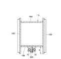
15は第2ブーム13の先端側に後述する第2の縦ピン19を用いて左,右方向に回動可能に連結された第2の腕部材としての第3ブームで、該第3ブーム15は、図2ないし図4に示すように、上,下方向で対面しつつ前,後方向に延びる上板15A,下板15Bと、これら上板15A,下板15Bを挟んで左,右方向で対面する左側板15C,右側板15Dとにより、全体として角筒状をなす強固な中空構造体として形成されている。また、上板15Aと下板15Bの前端部は、く字型に屈曲した連結板15Eによって連結されている(図2参照)。
ここで、図6に示すように、左,右の側板15C,15Dの下端部は、下板15Bの下面から下方に向けて突出寸法Aだけ突出しており、これら左,右の側板15C,15Dと下板15Bとによって囲まれる空間内には、後述するバケットシリンダ用油圧通路29の第3ブーム側パイプ32が配設される構成となっている。
Here, as shown in FIG. 6, the lower end portions of the left and
そして、図3等に示すように、第3ブーム15の基端側(第2ブーム13側)には、左側板15Cから左側方に突出する上,下一対のリンク取付板15Fが設けられている。そして、リンク取付板15Fには、後述するリンクロッド21の他端側がピン結合される構成となっている。また、左側板15Cのうちリンク取付板15Fの近傍部位には、後述するアームシリンダ用油圧通路28の第2ブーム側ホース28Bが挿通される長孔状のホース挿通孔15Gが穿設されている。
As shown in FIG. 3 and the like, the base end side (
16,16は第3ブーム15の基端側に設けられた取付ブラケットで、該各取付ブラケット16は、後述する第2の縦ピン19を用いて、第2ブーム13の先端側ボス13Bに左,右方向(水平方向)に回動可能にピン結合されるものである。ここで、各取付ブラケット16は、第2ブーム13の先端側ボス13Bを挟んで上,下方向で対向している。そして、図3及び図5に示すように、各取付ブラケット16には、後述する第2の縦ピン19が挿通されるピン挿通孔16Aが穿設されている。また、上側に位置する取付ブラケット16の上面側には、後述のストッパボルト20が径方向に挿通される円筒状のカラー16Bが固着して設けられている。
17は左,右の側板15C,15Dの基端側に設けられたシリンダ取付部で、該各シリンダ取付部17は、上板15Aから上方に突出して設けられ、後述するアームシリンダ26のボトム側が回動可能に取付けられるものである。18は左,右の側板15C,15Dの先端側に設けられたアーム取付部で、該アーム取付部18は、図2に示すように、連結板15Eから前方に突出して設けられ、後述のアーム22が上,下方向に回動可能に取付けられるものである。
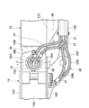
19は第2ブーム13と第3ブーム15との間を連結する第2の縦ピンで、該第2の縦ピン19は、図3ないし図5に示すように、第3ブーム15に設けた取付ブラケット16のピン挿通孔16Aと、第2ブーム13の先端側ボス13Bの内周側とに挿通されることにより、第2ブーム13に対し、第3ブーム15を左,右方向に回動可能に連結するものである。
ここで、第2の縦ピン19は、その内周側が軸方向に貫通する中空孔19Aとなった円筒状の中空パイプにより構成されている。そして、第2の縦ピン19を用いて第2ブーム13の先端側ボス13Bと第3ブーム15の取付ブラケット16とを連結した状態で、第2の縦ピン19の中空孔19A内には、後述の接続ホース34が配設される構成となっている。また、取付ブラケット16のカラー16Bと第2の縦ピン19の上端側との間には、径方向に延びるストッパボルト20が設けられ、該ストッパボルト20によって第2の縦ピン19を抜止め、廻止めする構成となっている。
Here, the 2nd
21は第1ブーム12と第3ブーム15との間に設けられたリンクロッドで、該リンクロッド21の一端側は、第1ブーム12の取付板12B,12C間にピン結合され、リンクロッド21の他端側は、第3ブーム15のリンク取付板15Fにピン結合されている。そして、リンクロッド21は、第1ブーム12に対し第3ブーム15を常に平行な状態に保つための平行リンクを構成するものである。
22は第3ブーム15の先端側に回動可能に取付けられたアームで、該アーム22は、全体として角筒状をなす強固な中空構造体として形成されている。そして、アーム22の基端側は、第3ブーム15のアーム取付部18に上,下方向に回動可能にピン結合され、アーム22の先端側には、バケット23が回動可能にピン結合されている。また、アーム22の基端側にはシリンダ取付板22Aが突設され、該シリンダ取付板22Aには、後述するアームシリンダ26のロッド側と、バケットシリンダ27のボトム側がピン結合されている。
24は上部旋回体3と第1ブーム12との間に設けられたブームシリンダで、該ブームシリンダ24は、上部旋回体3に対し第1ブーム12を上,下方向に回動(俯仰動)させるものである。25は第1ブーム12の取付板12C,12Dと第2ブーム13のシリンダ取付板13Cとの間に設けられたオフセットシリンダで、該オフセットシリンダ25は、第1ブーム12に対し第3ブーム15を左,右方向に平行移動(オフセット)させるものである。
26は第3ブーム15のシリンダ取付部17とアーム22のシリンダ取付板22Aとの間に設けられたアームシリンダで、該アームシリンダ26は、第3ブーム15に対しアーム22を上,下方向に回動させるものである。27はアーム22のシリンダ取付板22Aとバケット23との間に設けられたバケットシリンダで、該バケットシリンダ27は、アーム22に対しバケット23を回動させるものである。
26 is an arm cylinder provided between the
28はアームシリンダ用油圧通路で、該アームシリンダ用油圧通路28は、上部旋回体3側に設けられた油圧源(図示せず)とアームシリンダ26との間を接続し、アームシリンダ26に対し作動用の圧油を給排するものである。ここで、アームシリンダ用油圧通路28は、図2に示すように、第1ブーム12に配設された金属パイプ等からなる第1ブーム側パイプ28Aと、該第1ブーム側パイプ28Aの先端側に接続され第2ブーム13に配設された可撓性を有する第2ブーム側ホース28Bとを含んで構成されている。
ここで、第2ブーム側ホース28Bの基端側は、第1ブーム12の取付板12B上に設けられた継手28Cを介して、第1ブーム側パイプ28Aの先端側に接続されている。また、第2ブーム側ホース28Bは、第2ブーム13のホース保持部材13D内に保持された状態で、第2ブーム13に沿って第3ブーム15へと延びている。そして、第2ブーム側ホース28Bの先端側は、第3ブーム15の左側板15Cに形成されたホース挿通孔15Gを通じて左,右の側板15C,15D間に導出され、この左,右の側板15C,15D間に配置されたアームシリンダ26に接続されている。
Here, the base end side of the second
29はバケットシリンダ用油圧通路で、該バケットシリンダ用油圧通路29は、油圧源(図示せず)とバケットシリンダ27との間を接続し、バケットシリンダ27に対し作動用の圧油を給排するものである。ここで、バケットシリンダ用油圧通路29は、図2及び図3に示すように、後述の第1ブーム側パイプ30、第2ブーム側ホース31、第3ブーム側パイプ32、第3ブーム側ホース33、接続ホース34等により構成されている。なお、これら第1ブーム側パイプ30、第2ブーム側ホース31、第3ブーム側パイプ32、第3ブーム側ホース33、接続ホース34は、それぞれ供給用と排出用の2本のパイプまたはホースによって構成されている。
30,30は第1ブーム12に配設された第1ブーム側パイプで、該各第1ブーム側パイプ30は、例えば金属製のパイプ材等を用いて形成され、その基端側は、油圧ホース等を介して油圧源(いずれも図示せず)に接続されている。そして、第1ブーム側パイプ30は、第1ブーム12に沿って第2ブーム13側へと延び、その先端側は、第1ブーム12の取付板12B上に設けられた継手30Aを介して後述の第2ブーム側ホース31に接続されている。
30 and 30 are the 1st boom side pipes arrange | positioned at the
31,31は第2ブーム13に配設された第1の油圧配管としての第2ブーム側ホースで、該各第2ブーム側ホース31は、例えばゴム等の可撓性材料を用いて形成され、その基端側は継手30Aを介して第1ブーム側パイプ30の先端側に接続されている。そして、第2ブーム側ホース31は、第2ブーム13のホース保持部材13D内に保持された状態で、該第2ブーム13に沿って第3ブーム15へと延び、その先端側は、後述する接続ホース34の一端側に接続されている。
32,32は第3ブーム15に配設された第2の油圧配管としての第3ブーム側パイプで、該各第3ブーム側パイプ32は、例えば金属製のパイプ材等を用いて形成され、その基端側は、後述する接続ホース34の他端側に接続されている。そして、第3ブーム側パイプ32は、パイプ固定具32Aを用いて第3ブーム15の下板15Bに固定された状態で第3ブーム15に沿ってアーム22へと延び、その先端側は後述する第3ブーム側ホース33に接続されている。
32 and 32 are the 3rd boom side pipes as the 2nd hydraulic piping arranged in the
ここで、図6に示すように、第3ブーム15を構成する左,右の側板15C,15Dの下端部は、下板15Bから突出寸法Aだけ下向きに突出しているので、下板15Bに固定された第3ブーム側パイプ32を、左,右の側板15C,15Dによって左,右方向から覆うことにより、この第3ブーム側パイプ32を周囲の障害物から保護することができる構成となっている。
Here, as shown in FIG. 6, the lower ends of the left and
33は第3ブーム15からアーム22に亘って配設された第3ブーム側ホース(1本のみ図示)で、該第3ブーム側ホース33は、例えばゴム等の可撓性材料を用いて形成され、その基端側は、第3ブーム側パイプ32の先端側に接続されている。そして、第3ブーム側ホース33の先端側は、第3ブーム15の下板15Bから第3ブーム15の連結板15Eとアーム22との間の隙間を通じてアーム22のシリンダ取付部22Aへと延び、該シリンダ取付部22Aに取付けられたバケットシリンダ27に接続されている。
34,34は第2の縦ピン19の中空孔19A内に配設された接続配管としての接続ホースで、図3ないし図5に示すように、接続ホース34は、第1の油圧配管としての第2ブーム側ホース31と、第2の油圧配管としての第3ブーム側パイプ32との間を接続するものである。
34 and 34 are connection hoses as connection pipes disposed in the
ここで、接続ホース34は、例えばゴム等の可撓性材料を用いて形成され、第2の縦ピン19の中空孔19A内に遊挿された状態で、該第2の縦ピン19の軸方向に延びている。そして、接続ホース34の一端側(上端側)は継手34Aを介して第2ブーム側ホース31の先端側に接続され、接続ホース34の他端側(下端側)は継手34Bを介して第3ブーム側パイプ32の基端側に接続される構成となっている。
Here, the
このように、第2ブーム13と第3ブーム15との間を連結する第2の縦ピン19を、内周側が中空孔19Aとなった中空ピンによって構成し、バケットシリンダ用油圧通路29を構成する第2ブーム側ホース31と第3ブーム側パイプ32との間を、第2の縦ピン19の中空孔19A内に配設した接続ホース34によって接続することにより、第2ブーム13と第3ブーム15とが第2の縦ピン19を中心として相対回動したとしても、この第2,第3ブーム13,15の回動動作に追従して第2ブーム側ホース31が第2ブーム13の外部に大きくはみ出すのを抑えることができる構成となっている。
In this way, the second
本実施の形態による油圧ショベル1は上述の如き構成を有するもので、この油圧ショベル1を用いて側溝の掘削作業等を行うときには、まず、オフセットシリンダ25を作動させることにより、第2ブーム13、第3ブーム15、アーム22、バケット23等を上部旋回体3の左側または右側に平行移動(オフセット)させる。そして、掘削位置が決った状態で、ブームシリンダ24、アームシリンダ26、バケットシリンダ27等を伸縮させ、オフセットブーム12、アーム22、バケット23等を作動させることにより、側溝等を掘削することができる。
The
ここで、本実施の形態によれば、第2ブーム13と第3ブーム15との間を連結する第2の縦ピン19を、内周側が中空孔19Aとなった中空ピンによって構成し、バケットシリンダ27に作動用の圧油を給排するバケットシリンダ用油圧通路29のうち、第2ブーム側ホース31と第3ブーム側パイプ32との間を、第2の縦ピン19の中空孔19A内に配設した接続ホース34によって接続する構成としている。
Here, according to the present embodiment, the second
これにより、第2ブーム13と第3ブーム15とが第2の縦ピン19を中心として相対回動したとしても、この第2,第3ブーム13,15の回動動作に追従して第2ブーム側ホース31が大きく変形するのを抑えることができる。このため、第2ブーム側ホース31が、第2ブーム13の外部に大きくはみ出すのを抑えることができ、この第2ブーム側ホース31を外部の障害物等から保護することができる。
As a result, even if the
しかも、第2の縦ピン19の中空孔19A内に接続ホース34を遊挿し、この接続ホース34の一端側を継手34Aを介して第2ブーム側ホース31に接続し、他端側を継手34Bを介して第3ブーム側パイプ32に接続するだけであるから、例えば従来技術のように縦ピンの内部にロータリジョイントを設ける場合に比較して、第2の縦ピン19の構成を簡素化することができ、作業装置11の組立性の向上、製造コストの低減を図ることができる。
Moreover, the
また、本実施の形態では、第1の縦ピン19の中空孔19A内に配設した接続ホース34を介して、第2ブーム側ホース31と第3ブーム側パイプ32との間を接続することにより、第3ブーム側パイプ32を、第3ブーム15の下板15Bに沿って配設することができる。従って、例えばバケットシリンダ27に接続される配管を、第3ブーム15の左側板15Cに形成したホース挿通孔15Gを通じて上板15A側に導出し、この上板15Aに沿って配設する必要がない。
In the present embodiment, the second
このため、図2に示すように、第3ブーム15のホース挿通孔15Gには、アームシリンダ用油圧通路28の第2ブーム側ホース28Bのみを挿通すればよく、この分、ホース挿通孔15Gを小さく形成することができる。この結果、ホース挿通孔15Gを設けることによる第3ブーム15の強度低下を抑え、補強部材等の部品を減少させることができるので、作業装置11全体の重量を低減することができる上に、製造コストの低減にも寄与することができる。
For this reason, as shown in FIG. 2, only the second
また、第3ブーム側パイプ32を、第3ブーム15の下板15Bに沿って配設することができるので、例えばバケットシリンダ27に接続される配管を、第3ブーム15の上板15Aとアームシリンダ26との間の狭隘なスペース内に配設する場合に比較して、設計の自由度を高めることができる。
Further, since the third
さらに、第3ブーム側パイプ32を第3ブーム15の下板15Bに沿って配設することにより、該第3ブーム側パイプ32の先端側に接続される第3ブーム側ホース33を、第3ブーム15の連結板15Eとアーム22との間の隙間を通じてバケットシリンダ27へと延ばすことができる。これにより、第3ブーム15の連結板15Eとアーム22との間に形成される隙間を、第3ブーム側ホース33が通るだけの狭幅な隙間にすることができる。この結果、アーム取付部18が設けられた第3ブーム15の先端側の強度低下を抑え、補強部材等の部品を減少させることができるので、作業装置11全体の重量の低減、製造コストの低減にも寄与することができる。
Further, by arranging the third
しかも、図6に示すように、第3ブーム15を構成する左,右の側板15C,15Dの下端部は、下板15Bから突出寸法Aだけ下向きに突出しているので、下板15Bに固定された第3ブーム側パイプ32を、左,右の側板15C,15Dによって左,右方向から覆うことができる。これにより、第3ブーム側パイプ32を周囲の障害物から保護することができる。
Moreover, as shown in FIG. 6, the lower ends of the left and
次に、図7ないし図9は本発明の第2の実施の形態を示し、本実施の形態の特徴は、縦ピンに軸方向に貫通する油孔を設け、この油孔の軸方向の一側に第1の油圧配管を接続し、油孔の軸方向の他側に第2の油圧配管を接続する構成としたことにある。なお、本実施の形態では、上述した第1の実施の形態と同一の構成要素に同一符号を付し、その説明を省略するものとする。 Next, FIG. 7 to FIG. 9 show a second embodiment of the present invention. The feature of this embodiment is that an oil hole penetrating in the axial direction is provided in a vertical pin, and one axial direction of this oil hole is provided. The first hydraulic piping is connected to the side, and the second hydraulic piping is connected to the other side in the axial direction of the oil hole. In the present embodiment, the same components as those in the first embodiment described above are denoted by the same reference numerals, and the description thereof is omitted.
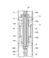
図において、41は第2ブーム13と第3ブーム15との間を連結する第2の縦ピンで、該第2の縦ピン41は、第1の実施の形態による第2の縦ピン19に代えて本実施の形態に用いたものである。ここで、本実施の形態による第2の縦ピン41は、図7ないし図9に示すように、円柱状をなす中実な丸棒材により構成され、その内部には後述の各油孔43が設けられている。
In the figure,
そして、第2の縦ピン41は、第3ブーム15に設けた取付ブラケット16のピン挿通孔16Aと、第2ブーム13の先端側ボス13Bの内周側とに挿通されることにより、第2ブーム13に対し、第3ブーム15を左,右方向に(水平方向)に回動可能に連結するものである。
The second
42はバケットシリンダ用油圧通路で、該バケットシリンダ用油圧通路42は、第1の実施の形態によるバケットシリンダ用油圧通路29とほぼ同様に、第1ブーム側パイプ30(図2参照)、第2ブーム側ホース31、第3ブーム側パイプ32、第3ブーム側ホース33(図2参照)、後述の各油孔43等により構成されている。
43,43は第2の縦ピン41に設けられた2個の油孔で、これら各油孔43は、第1の実施の形態による接続ホース34に代えて本実施の形態に用いたもので、バケットシリンダ用油圧通路42の一部を構成するものである。ここで、各油孔43は、第2の縦ピン41の径方向に離間して配置され、第2の縦ピン41の軸方向に貫通している。また、各油孔43の軸方向の一端側43Aの開口端と、軸方向の他端側43Bの開口端とには、それぞれ雌ねじ穴が螺設されている。
そして、各油孔43の一端側43Aには、第1の油圧配管としての第2ブーム側ホース31が後述のスイベル継手44を介して接続され、各油孔43の他端側43Bには、第2の油圧配管としての第3ブーム側パイプ32が後述のスイベル継手45を介して接続されている。
Then, a second
44は油孔43の一端側43Aと第2ブーム側ホース31との接続部に設けられたスイベル継手で、該スイベル継手44は、油孔43の一端側43Aに螺合する固定継手部44Aと、該固定継手部44Aの軸中心を中心として回転する回転継手部44Bとにより構成されている。従って、第2の縦ピン41を中心として第2ブーム13に対し第3ブーム15が左,右方向に回動したときには、油孔43の一端側43Aに接続されたスイベル継手44の固定継手部44Aに対し、油孔43を中心として回転継手部44Bが水平方向に回動することにより、この回転継手部44Bに接続された第2ブーム側ホース31の捩じれを抑えることができる構成となっている。
45は油孔43の他端側43Bと第3ブーム側パイプ32との接続部に設けられたスイベル継手で、該スイベル継手45は、油孔43の他端側43Bに螺合する固定継手部45Aと、該固定継手部45Aの軸中心を中心として回転する回転継手部45Bとにより構成されている。従って、第2の縦ピン41を中心として第2ブーム13に対し第3ブーム15が左,右方向に回動したときには、油孔43の一端側43Aに接続されたスイベル継手45の固定継手部45Aに対し、油孔43を中心として回転継手部45Bが水平方向に回動することにより、この回転継手部45Bに接続された第3ブーム側パイプ32を、第3ブーム15の回動動作に追従させることができる構成となっている。
本実施の形態による油圧ショベルは上述の如き構成を有するもので、その基本的作動については上述した第1の実施の形態によるものと格別差異はない。 The hydraulic excavator according to the present embodiment has the above-described configuration, and the basic operation thereof is not particularly different from that according to the first embodiment described above.
然るに、本実施の形態によれば、第2ブーム13と第3ブーム15との間を連結する第2の縦ピン41に、軸方向に貫通する油孔43,43を穿設し、これら各油孔43の軸方向の一端側43Aには第2ブーム側ホース31を接続し、各油孔43の軸方向の他端側43Bには第3ブーム側パイプ32を接続する構成としている。
However, according to the present embodiment, the second
このため、第2ブーム側ホース31と第3ブーム側パイプ32との間を、別部材からなる配管類を介して接続する必要がなく、この配管類が周囲の障害物に接触して破損することがないので、作業装置11の信頼性を高めることができる。
For this reason, it is not necessary to connect between the 2nd
しかも、油孔43の一端側43Aと第2ブーム側ホース31との接続部にはスイベル継手44を設け、油孔43の他端側43Bと第3ブーム側パイプ32との接続部にはスイベル継手45を設ける構成としている。これにより、第2の縦ピン41を中心として第2ブーム13に対し第3ブーム15が左,右方向に回動したときに、第2ブーム側ホース31が捩じれるのをスイベル継手44によって抑えることができる。また、第3ブーム15に固定して設けられた第3ブーム側パイプ32を、第3ブーム15の回動動作に適正に追従させることができる。
Moreover, a swivel joint 44 is provided at the connection portion between the one
なお、上述した第1の実施の形態では、第2ブーム13と第3ブーム15との間を連結する第2の縦ピン19の中空孔19A内に接続ホース34を配設し、この接続ホース34の一端側を継手34Aを介して第2ブーム側ホース31に接続し、接続ホース34の他端側を継手34Bを介して第3ブーム側パイプ32に接続した場合を例示している。しかし、本発明はこれに限るものではなく、例えば図10に示す変形例のように、第2ブーム側ホース31の先端側を延長して第2の縦ピン19の中空孔19A内に挿通し、第2の縦ピン19から突出した第2ブーム側ホース31の先端部を継手46を介して第3ブーム側パイプ32に接続する構成としてもよい。
In the first embodiment described above, the
また、上述した第1の実施の形態では、第3ブーム15に固定される第2の油圧配管として、金属等のパイプ材からなる第3ブーム側パイプ32を用いた場合を例示している。しかし、本発明はこれに限らず、例えば可撓性を有するホースによって第2の油圧配管を構成してもよい。このことは、第2の実施の形態についても同様である。
Further, in the first embodiment described above, the case where the third
また、上述した第1の実施の形態では、第2ブーム13を第1の腕部材とし、第3ブーム15を第2の腕部材とし、これら第2ブーム13と第3ブーム15との間を連結する第2の縦ピン19に中空孔19Aを設け、この中空孔19A内にバケットシリンダ用油圧通路29の一部を構成する接続ホース34を配設した場合を例示している。しかし、本発明はこれに限るものではなく、例えば第1ブーム12を第1の腕部材とし、第2ブーム13を第2の腕部材とし、これら第1ブーム12と第2ブーム13との間を連結する第1の縦ピン14に中空孔を設け、当該中空孔内に接続ホースを配設する構成としてもよい。
In the first embodiment described above, the
また、第2の縦ピン19のみに中空孔19Aを設けるだけでなく、第1の縦ピン14と第2の縦ピン19との両方に中空孔を設け、これら第1,第2の縦ピン14,19に設けた中空孔に、バケットシリンダ用油圧通路29の一部を構成する接続ホースを配設する構成としてもよい。
Further, not only the
また、上述した第2の実施の形態では、第2ブーム13を第1の腕部材とし、第3ブーム15を第2の腕部材とし、これら第2ブーム13と第3ブーム15との間を連結する第2の縦ピン41に、バケットシリンダ用油圧通路42の一部を構成する油孔43を設けた場合を例示している。しかし、本発明はこれに限らず、例えば第1ブーム12を第1の腕部材とし、第2ブーム13を第2の腕部材とし、これら第1ブーム12と第2ブーム13との間を連結する第1の縦ピンに、バケットシリンダ用油圧通路42の一部を構成する油孔を設ける構成としてもよい。
In the second embodiment described above, the
また、第2の縦ピン41に油孔43を設けるだけでなく、第1の縦ピン14と第2の縦ピン41との両方に、バケットシリンダ用油圧通路42の一部を構成する油孔を設ける構成としてもよい。
Further, not only the
また、上述した第2の実施の形態では、第2の縦ピン41に設けた油孔43の一端側43Aにスイベル継手44を設け、油孔43の他端側43Bにスイベル継手45を設けた場合を例示している。しかし、本発明はこれに限るものではなく、例えば油孔43の他端側43Bのみにスイベル継手45を設ける構成としてもよい。
In the second embodiment described above, the swivel joint 44 is provided on one
さらに、上述した実施の形態では、第1ブーム12、第2ブーム13、第3ブーム15からなるオフセットブーム式の作業装置11を備えた油圧ショベルを例示している。しかし、本発明はこれに限らず、例えばロアブームとアッパブームとからなるオフセットブーム式の作業装置を備えた油圧ショベルにも適用することができる。
Furthermore, in embodiment mentioned above, the hydraulic shovel provided with the offset boom
1 油圧ショベル(建設機械)
2 下部走行体(走行体)
3 上部旋回体(走行体)
11 作業装置
12 第1ブーム
13 第2ブーム
14 第1の縦ピン
15 第3ブーム
15A 上板
15B 下板
15C 左側板
15D 右側板
19,41 第2の縦ピン
19A 中空孔
22 アーム
23 バケット
24 ブームシリンダ(油圧アクチュエータ)
25 オフセットシリンダ(油圧アクチュエータ)
26 アームシリンダ(油圧アクチュエータ)
27 バケットシリンダ(油圧アクチュエータ)
29,42 バケットシリンダ用油圧通路
31 第2ブーム側ホース(第1の油圧配管)
32 第3ブーム側パイプ(第2の油圧配管)
34 接続ホース(接続配管)
43 油孔
44,45 スイベル継手
1 Excavator (construction machine)
2 Lower traveling body (running body)
3 Upper swing body (running body)
DESCRIPTION OF
25 Offset cylinder (hydraulic actuator)
26 Arm cylinder (hydraulic actuator)
27 Bucket cylinder (hydraulic actuator)
29, 42 Bucket cylinder
32 Third boom side pipe (second hydraulic piping)
34 Connection hose (connection piping)
43
Claims (5)
前記作業装置は、第1の腕部材と、縦ピンを介して該第1の腕部材に左,右方向に回動可能に連結された第2の腕部材と、前記油圧アクチュエータに圧油を供給するために前記第1の腕部材に配設された第1の油圧配管と、前記第2の腕部材に配設された第2の油圧配管とにより構成してなる建設機械において、
前記縦ピンは内周側が軸方向に貫通する中空孔となった中空ピンにより構成し、該縦ピンの中空孔内には、前記第1の油圧配管と第2の油圧配管との間を接続する接続配管を配設する構成としたことを特徴とする建設機械。 A self-propelled traveling body, and a working device provided on the traveling body and operated by a hydraulic actuator,
The working device includes a first arm member, a second arm member connected to the first arm member via a vertical pin so as to be rotatable left and right, and pressure oil to the hydraulic actuator. In a construction machine constituted by a first hydraulic pipe disposed on the first arm member for supply and a second hydraulic pipe disposed on the second arm member,
The vertical pin is constituted by a hollow pin whose inner peripheral side is a hollow hole penetrating in the axial direction, and the first hydraulic pipe and the second hydraulic pipe are connected in the hollow hole of the vertical pin. A construction machine characterized in that a connecting pipe is provided.
前記作業装置は、第1の腕部材と、縦ピンを介して該第1の腕部材に左,右方向に回動可能に連結された第2の腕部材と、前記油圧アクチュエータに圧油を供給するために前記第1の腕部材に配設された第1の油圧配管と、前記第2の腕部材に配設された第2の油圧配管とにより構成してなる建設機械において、
前記縦ピンには軸方向に貫通する油孔を設け、該油孔の軸方向の一側には前記第1の油圧配管を接続し、前記油孔の軸方向の他側には前記第2の油圧配管を接続する構成としたことを特徴とする建設機械。 A self-propelled traveling body, and a working device provided on the traveling body and operated by a hydraulic actuator,
The working device includes a first arm member, a second arm member connected to the first arm member via a vertical pin so as to be rotatable left and right, and pressure oil to the hydraulic actuator. In a construction machine constituted by a first hydraulic pipe disposed on the first arm member for supply and a second hydraulic pipe disposed on the second arm member,
The vertical pin is provided with an oil hole penetrating in the axial direction, the first hydraulic pipe is connected to one axial side of the oil hole, and the second hydraulic pipe is connected to the other axial side of the oil hole. Construction machinery characterized in that it is configured to connect the hydraulic piping.
前記第2の油圧配管は、前記左,右の側板により左,右方向から覆われた状態で前記下板に沿って配置する構成としてなる請求項1または2に記載の建設機械。 The second arm member includes an upper plate and a lower plate extending in the front and rear directions while facing in the upper and lower directions, and a left plate and a right plate facing in the left and right directions with the upper plate and the lower plate interposed therebetween. And consisting of
The construction machine according to claim 1 or 2, wherein the second hydraulic pipe is arranged along the lower plate in a state of being covered from the left and right directions by the left and right side plates.
前記縦ピンは、前記第1,第2の縦ピンのうち少なくとも一方の縦ピンである請求項1,2,3または4に記載の建設機械。 The working device uses a first boom that is attached to the traveling body and moves up and down by a boom cylinder and serves as the first arm member, and a first vertical pin on the distal end side of the first boom. And a second boom that is connected to the left and right by an offset cylinder and serves as the first or second arm member, and a second vertical pin on the tip side of the second boom. A third boom that is held in parallel to the first boom by a link rod in a state of being pivotally connected to the first boom, and is configured as an offset boom type working device.
The construction machine according to claim 1, 2, 3, or 4, wherein the vertical pin is at least one vertical pin of the first and second vertical pins.
Priority Applications (1)
| Application Number | Priority Date | Filing Date | Title |
|---|---|---|---|
| JP2007167703A JP2009007760A (en) | 2007-06-26 | 2007-06-26 | Construction machine |
Applications Claiming Priority (1)
| Application Number | Priority Date | Filing Date | Title |
|---|---|---|---|
| JP2007167703A JP2009007760A (en) | 2007-06-26 | 2007-06-26 | Construction machine |
Publications (1)
| Publication Number | Publication Date |
|---|---|
| JP2009007760A true JP2009007760A (en) | 2009-01-15 |
Family
ID=40323114
Family Applications (1)
| Application Number | Title | Priority Date | Filing Date |
|---|---|---|---|
| JP2007167703A Pending JP2009007760A (en) | 2007-06-26 | 2007-06-26 | Construction machine |
Country Status (1)
| Country | Link |
|---|---|
| JP (1) | JP2009007760A (en) |
Cited By (3)
| Publication number | Priority date | Publication date | Assignee | Title |
|---|---|---|---|---|
| NL2004784C2 (en) * | 2010-05-31 | 2011-12-01 | Hudson Bay Holding B V | BELT WORK ARM WITH IMPROVED FITTING OF THE PIPES. |
| JP2017066781A (en) * | 2015-09-30 | 2017-04-06 | ヤンマー株式会社 | Hydraulic drive construction machine |
| CN106869218A (en) * | 2017-04-13 | 2017-06-20 | 广西柳工机械股份有限公司 | Loading machine is pitched with deflectable armful |
-
2007
- 2007-06-26 JP JP2007167703A patent/JP2009007760A/en active Pending
Cited By (7)
| Publication number | Priority date | Publication date | Assignee | Title |
|---|---|---|---|---|
| NL2004784C2 (en) * | 2010-05-31 | 2011-12-01 | Hudson Bay Holding B V | BELT WORK ARM WITH IMPROVED FITTING OF THE PIPES. |
| US9260833B2 (en) | 2010-05-31 | 2016-02-16 | Hudson Bay Holding B.V. | Articulated operating arm with mechanical locking between arm sections |
| US20160122162A1 (en) * | 2010-05-31 | 2016-05-05 | Hudson Bay Holding B.V. | Articulated Operating Arm with Mechanical Locking Means between Arm Sections |
| US9637357B2 (en) * | 2010-05-31 | 2017-05-02 | Hudson Bay Holding B.V. | Articulated operating arm with swivel joint mechanism |
| JP2017066781A (en) * | 2015-09-30 | 2017-04-06 | ヤンマー株式会社 | Hydraulic drive construction machine |
| CN106869218A (en) * | 2017-04-13 | 2017-06-20 | 广西柳工机械股份有限公司 | Loading machine is pitched with deflectable armful |
| CN106869218B (en) * | 2017-04-13 | 2020-09-18 | 广西柳工机械股份有限公司 | Deflectable holding fork for loader |
Similar Documents
| Publication | Publication Date | Title |
|---|---|---|
| JP4256359B2 (en) | Construction equipment working equipment | |
| JP2010112094A (en) | Construction machine | |
| JP2009007760A (en) | Construction machine | |
| JP3967501B2 (en) | Swivel construction machine | |
| JP5314625B2 (en) | Working arm for construction machinery | |
| JP2009133084A (en) | Offset boom type front device | |
| JP2004108055A (en) | Working device of construction machine | |
| JP2013237996A (en) | Construction machine | |
| JP6731383B2 (en) | Work machine | |
| JP2002266374A (en) | Construction machinery | |
| JP6782262B2 (en) | Short reach type hydraulic excavator | |
| JP3535079B2 (en) | Hydraulic piping structure of construction machinery | |
| JP2023131836A (en) | Protector and work machine | |
| JP6934459B2 (en) | Construction machinery | |
| JP5996498B2 (en) | Excavator working equipment | |
| JP2000282508A (en) | Construction machine | |
| JP3602770B2 (en) | Offset boom type construction machine | |
| JP2019218784A (en) | Swivel work vehicle | |
| JP2007277930A (en) | Working device of construction machine | |
| JP5253961B2 (en) | Construction machinery | |
| JP2004036234A (en) | Revolving construction machine | |
| JP2005060976A (en) | Swivel type construction machinery | |
| JP2855501B2 (en) | Work machine | |
| JP2005307598A (en) | Construction machine | |
| JP2002275935A (en) | Hydraulic piping structure for construction machine |