JP6068681B2 - Scissor-type telescopic structure - Google Patents
Scissor-type telescopic structure Download PDFInfo
- Publication number
- JP6068681B2 JP6068681B2 JP2015556302A JP2015556302A JP6068681B2 JP 6068681 B2 JP6068681 B2 JP 6068681B2 JP 2015556302 A JP2015556302 A JP 2015556302A JP 2015556302 A JP2015556302 A JP 2015556302A JP 6068681 B2 JP6068681 B2 JP 6068681B2
- Authority
- JP
- Japan
- Prior art keywords
- scissors
- frame
- type
- bridge
- expansion
- Prior art date
- Legal status (The legal status is an assumption and is not a legal conclusion. Google has not performed a legal analysis and makes no representation as to the accuracy of the status listed.)
- Expired - Fee Related
Links
- 238000003780 insertion Methods 0.000 claims description 8
- 230000037431 insertion Effects 0.000 claims description 8
- 238000012986 modification Methods 0.000 description 15
- 230000004048 modification Effects 0.000 description 10
- 238000003860 storage Methods 0.000 description 7
- 239000000725 suspension Substances 0.000 description 6
- 238000010276 construction Methods 0.000 description 5
- XLYOFNOQVPJJNP-UHFFFAOYSA-N water Substances O XLYOFNOQVPJJNP-UHFFFAOYSA-N 0.000 description 5
- 239000000463 material Substances 0.000 description 4
- 230000004308 accommodation Effects 0.000 description 3
- 239000010720 hydraulic oil Substances 0.000 description 3
- 238000009434 installation Methods 0.000 description 3
- 230000035882 stress Effects 0.000 description 3
- 229910000838 Al alloy Inorganic materials 0.000 description 2
- 230000032683 aging Effects 0.000 description 2
- 230000007246 mechanism Effects 0.000 description 2
- 238000000034 method Methods 0.000 description 2
- 230000008439 repair process Effects 0.000 description 2
- 229910000861 Mg alloy Inorganic materials 0.000 description 1
- 229910000831 Steel Inorganic materials 0.000 description 1
- 238000013461 design Methods 0.000 description 1
- 238000011161 development Methods 0.000 description 1
- 230000018109 developmental process Effects 0.000 description 1
- 230000000694 effects Effects 0.000 description 1
- 238000001125 extrusion Methods 0.000 description 1
- 238000004519 manufacturing process Methods 0.000 description 1
- 239000003921 oil Substances 0.000 description 1
- 230000002787 reinforcement Effects 0.000 description 1
- 230000003014 reinforcing effect Effects 0.000 description 1
- 230000007480 spreading Effects 0.000 description 1
- 238000003892 spreading Methods 0.000 description 1
- 230000006641 stabilisation Effects 0.000 description 1
- 238000011105 stabilization Methods 0.000 description 1
- 239000010959 steel Substances 0.000 description 1
- 239000013585 weight reducing agent Substances 0.000 description 1
Images


Classifications
-
- E—FIXED CONSTRUCTIONS
- E01—CONSTRUCTION OF ROADS, RAILWAYS, OR BRIDGES
- E01D—CONSTRUCTION OF BRIDGES, ELEVATED ROADWAYS OR VIADUCTS; ASSEMBLY OF BRIDGES
- E01D15/00—Movable or portable bridges; Floating bridges
- E01D15/12—Portable or sectional bridges
- E01D15/124—Folding or telescopic bridges; Bridges built up from folding or telescopic sections
-
- E—FIXED CONSTRUCTIONS
- E01—CONSTRUCTION OF ROADS, RAILWAYS, OR BRIDGES
- E01D—CONSTRUCTION OF BRIDGES, ELEVATED ROADWAYS OR VIADUCTS; ASSEMBLY OF BRIDGES
- E01D15/00—Movable or portable bridges; Floating bridges
- E01D15/14—Floating bridges, e.g. pontoon bridges
Landscapes
- Engineering & Computer Science (AREA)
- Architecture (AREA)
- Civil Engineering (AREA)
- Structural Engineering (AREA)
- Bridges Or Land Bridges (AREA)
Description
本発明は、シザーズ構造を含むシザーズ式伸縮構造に関するものである。 The present invention relates to a scissors-type elastic structure including a scissors structure.
従来より、台風や梅雨の大雨、ゲリラ豪雨、津波などによって、橋が流される事象や地震等によって橋が損傷する事象が数多く発生し、橋を迅速に復旧させる技術が求められている。また、小さな橋でも建設コストを抑えるために、橋を短期に建設することは重要なことである。 Conventionally, many typhoons, heavy rains in the rainy season, heavy guerrilla rain, tsunami, etc. have caused many events that cause the bridge to be washed away or damage the bridge due to earthquakes. In addition, it is important to build a bridge in a short time in order to reduce the construction cost of a small bridge.
従来は、災害現場であれば、民間の工事用車両を通行可能とするため、重厚な鋼鉄製の仮設桁橋やトラス橋の各部材が運搬され、現場の状況に応じた組立で架設されてきた。災害に限らず、張出し工法やベント支持工法、押出し工法による構造物の架設方法は一般的であり、その架設の工期も数日はかかっていた。 In the past, heavy steel temporary girder bridges and truss bridge members have been transported and built in an assembly according to the situation at the disaster site so that private construction vehicles can pass through. It was. In addition to disasters, the construction method of structures by the overhang method, vent support method, and extrusion method is common, and the construction period of the construction took several days.
ところで、特許文献1のような、せん断補強用展開型シザーズリンクが知られている。このシザーズリンクは、運搬、保管等のときは嵩張らず使用時には展開して所望の構成及び長さとすることができる。 By the way, the deployment type scissors link for shear reinforcement like patent document 1 is known. This scissor link is not bulky during transportation, storage, etc., and can be deployed during use to have a desired configuration and length.
特許文献1のような、シザーズ(はさみ)機構は、従来より橋などの大型の建造物には適用されにくかった。その理由として、機能に対する効用が少なく、制御装置を伴うために製造コストが割高となる、構造体として制御部材を入れないと不安定な構造体になりかねない、一方向は堅牢な剛性を持つがそれと異なる方向はぜい弱な剛性となりがちである等という点が考えられる。また、部材交差部のヒンジ部(ピボット)の存在による応力集中や摩耗など構造強度に対する保証が設計上難しいという問題がある。 The scissors mechanism as in Patent Document 1 has been difficult to apply to large buildings such as bridges. The reason for this is that there is little utility for the function, the manufacturing cost is high due to the accompanying control device, and if the control member is not inserted as a structure, it may become an unstable structure, and it has robust rigidity in one direction. However, it can be considered that weak directions tend to be weak in other directions. In addition, there is a problem in that it is difficult to design for structural strength such as stress concentration and wear due to the presence of a hinge portion (pivot) at the member intersection.
そこで、伸張時に安定すると共に、車等が走行可能となるように床版を設けると、部品点数が増えると共に、再び折り畳むときに床版を水平な状態から起立させるためには、水平な方向からでは非常に大きな力が必要となる上、床版の分だけ部品点数が増えて構造や機構が複雑となる。 Therefore, if the floor slab is provided so that it can be stable when extended and the car can run, the number of parts increases, and in order to stand the floor slab from a horizontal state when it is folded again, However, a very large force is required, and the number of parts increases by the amount of the floor slab, resulting in a complicated structure and mechanism.
本発明は、かかる点に鑑みてなされたものであり、その目的とするところは、簡単な構造で、運搬、収納及び展開が容易なシザーズ式伸縮構造を得ることにある。 This invention is made | formed in view of this point, The place made into the objective is to obtain the scissors type expansion-contraction structure with easy structure, and easy to carry, store, and expand | deploy.
上記の目的を達成するために、この発明では、床版部材を設けることなく、シザーズ構造を完全に伸張させた状態で上面をほぼ平坦にするようにした。 In order to achieve the above object, according to the present invention, the upper surface is made substantially flat in a state where the scissors structure is completely extended without providing a floor slab member.
具体的には、第1の発明では、
伸張方向へ伸縮可能なシザーズ式伸縮構造を対象とする。Specifically, in the first invention,
A scissors-type telescopic structure that can be expanded and contracted in the extension direction is targeted.
そして、上記シザーズ式伸縮構造は、
中央部分で互いにピン結合された2本のフレーム部材を含むフレーム要素が複数個該フレーム部材の先端部で互いにピン結合されたシザーズフレームを有し、
上記シザーズフレームの伸張時において、上記フレーム要素における手前側の上記フレーム部材が直線状にそれぞれ連結されると共に、奥側の上記フレーム部材が直線状にそれぞれ連結されることにより、上記フレーム部材の上面が連続した平坦面が形成される。And the scissors-type elastic structure is
A plurality of frame elements including two frame members that are pin-coupled to each other at the central portion have a scissor frame that is pin-coupled to each other at the tip of the frame member;
When the scissor frame is extended, the frame members on the front side of the frame element are linearly connected to each other, and the frame members on the back side are connected to each other in a straight line, so that the upper surface of the frame member is A continuous flat surface is formed.
上記の構成によると、シザーズフレームを完全に伸張させたときにフレーム部材の上面が平坦となるので、床版部材を別に設けなくても、安定し、フレーム部材の上面を床版と同じ役割を有するような版を兼ね、その上を人や車が通行することができる。シザーズ式伸縮橋が床版部材を含まないので、床版部材を含むときのような水平な状態から起立させて収納するときに大きな力が必要とならない。また、床版部材を含まないため、部品点数が減って構造が簡単になると共に、軽量化を図ることができる。なお、ここでいう平坦面とは、完全にフラットな状態のみをいうのではなく、人や車が通過可能な状態をつくり、路面が多少のでこぼこがある場合も含む。また、伸張後の床部材の上にさらに板状の部材を載置してボルト等によって強固に一体化させてもよい。 According to the above configuration, since the upper surface of the frame member becomes flat when the scissors frame is fully extended, the upper surface of the frame member plays the same role as the floor slab without providing a separate floor slab member. It also serves as a version that you have, and people and cars can pass through it. Since the scissors-type expansion bridge does not include a floor slab member, a large force is not required when standing up and storing from a horizontal state as when including a floor slab member. Further, since the floor slab member is not included, the number of parts is reduced, the structure is simplified, and the weight can be reduced. In addition, the flat surface here means not only a completely flat state but also a case where a state where a person or a vehicle can pass and the road surface is somewhat uneven is included. Further, a plate-like member may be placed on the extended floor member and firmly integrated with a bolt or the like.
第2の発明では、第1の発明に加え、
上記シザーズフレームが奥側に向かって複数並べられることにより、上記シザーズフレームの伸張時に橋桁となる構成とする。In the second invention, in addition to the first invention,
By arranging a plurality of scissors frames toward the back side, a bridge girder is formed when the scissors frame is extended.
上記の構成によると、橋桁として使用するときに奥側に複数のシザーズフレームを並べれば、幅方向の距離を稼ぐことができる。 According to the above configuration, when a plurality of scissors frames are arranged on the back side when used as a bridge girder, a distance in the width direction can be earned.
第3の発明では、第1又は第2の発明に加え、
フレーム部材は、中央部分に設けた中央ピン挿通孔を有するシザーズ本体と、該シザーズ本体の上側に設けられ、上記平坦面を形成する床部材とを備えている構成とする。In the third invention, in addition to the first or second invention,
The frame member includes a scissors body having a center pin insertion hole provided in the center portion, and a floor member provided on the scissors body and forming the flat surface.
上記の構成によると、1つのフレーム部材でシザーズ構造と床版構造の機能を有するので、部品点数が減って組立が容易である。 According to said structure, since it has the function of a scissors structure and a floor slab structure with one frame member, a number of parts reduces and an assembly is easy.
第4の発明では、第1乃至第3のいずれか1つの発明において、
上記伸張時のシザーズフレームは、平面視で互いのフレーム部材の接続する箇所が、手前側と奥側とでずれている。In a fourth invention, in any one of the first to third inventions,
In the scissors frame at the time of extension, the positions where the frame members are connected to each other are shifted between the front side and the back side in plan view.
上記の構成によると、接続箇所をずらすことで、重量物が通過するときに加わる荷重による応力集中が分散される。 According to said structure, the stress concentration by the load added when a heavy article passes is disperse | distributed by shifting a connection location.
第5の発明では、第1乃至第4のいずれか1つの発明において、
上記シザーズフレームの下端側が複数のポンツーンに支持され、伸張時に隣接するポンツーン間の距離を広げることで伸張される。In a fifth invention, in any one of the first to fourth inventions,
The scissors frame is supported at its lower end by a plurality of pontoons, and is expanded by increasing the distance between adjacent pontoons during expansion.
上記の構成によると、ポンツーンを連結して水面上を曳航し、現場でポンツーン間の距離を広げれば、ポンツーンに下端が支持された状態で水面上に仮設橋を容易に設置することができる。 According to said structure, if a pontoon is connected and towed on the water surface and the distance between pontoons is expanded on the spot, a temporary bridge can be easily installed on the water surface in the state where the lower end was supported by the pontoon.
第6の発明では、第1乃至第4のいずれか1つの発明に加え、
トレーラの荷台に載置可能であると共に、該荷台の外側で上下方向に延びて自重を支えるアウトリガーを備えている。In the sixth invention, in addition to any one of the first to fourth inventions,
An outrigger that can be placed on a trailer loading platform and that extends in the vertical direction outside the loading platform to support its own weight is provided.
上記の構成によると、収納状態のシザーズ式伸縮構造をトレーラの荷台に積んで運搬でき、現場でアウトリガーを用いて荷台を地面等に載置した後、トレーラを移動させ、展開することにより、仮設橋等を極めて迅速且つ容易に設けることができる。撤去時も収納してトレーラで運び出すときにアウトリガーがあるので、クレーンで吊り上げなくても荷台上に載せることができる。このように、アウトリガーを用いることで、クレーンなどの特別な機械を用意しなくても、シザーズ式伸縮構造の積み込み及び積み降ろしを容易に行うことができる。 According to the above configuration, the scissors-type telescopic structure in the stowed state can be transported by loading it on the trailer platform, and after placing the platform on the ground using the outrigger on the site, moving the trailer and deploying it temporarily Bridges and the like can be provided very quickly and easily. Since there is an outrigger when it is stored and removed by a trailer, it can be placed on the loading platform without being lifted by a crane. Thus, by using an outrigger, it is possible to easily load and unload the scissors-type telescopic structure without preparing a special machine such as a crane.
以上説明したように、本発明によれば、シザーズフレームを伸張させた状態でその上面が平坦になるようにしたので、簡単な構造で、運搬、収納及び展開が容易で展開時には安定した構造となるシザーズ式伸縮構造を得ることができる。 As described above, according to the present invention, since the upper surface of the scissors frame is flattened in a stretched state, the structure is simple, easy to transport, store and deploy, and stable when deployed. A scissors-type stretchable structure can be obtained.
以下、本発明の実施形態を図面に基づいて説明する。 Hereinafter, embodiments of the present invention will be described with reference to the drawings.
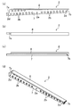
図1は、本発明の実施形態のシザーズ式伸縮構造としてのシザーズ式伸縮橋1を伸張させる状態を示し、図2は、このシザーズ式伸縮橋1の収納時を示し、図3は、図2の状態から起立させた状態を示す。このシザーズ式伸縮橋1は、伸張方向へ伸縮可能で最大伸張時にフラットとなるように構成されている。具体的には、図4〜図6にも示すように、このシザーズ式伸縮橋1は、中央部分の中央ピン挿通孔2a(図6に示す)でピン結合された2本のフレーム部材2(図6及び図7参照)を含むフレーム要素3(図4には4つある)が、複数個、フレーム部材2の先端部で互いにピン結合されたシザーズフレーム4を備えている。フレーム部材2は、両端に先端ピン挿通孔2dが開口され、軽量化のための複数の貫通孔2bが設けられたシザーズ本体7と、このシザーズ本体7の上側に設けられ、平坦面を形成する床部材8とを備えている。フレーム部材2は、例えば軽量で剛性の高い中空のアルミニウム合金押出材で一体や、3次元最適形状のビルト部材で構成してもよいし、シザーズ本体7と床部材8とを別々の材料で構成して組み付けるようにしてもよい。1つのフレーム部材2でシザーズ構造と床版構造の機能を有するので、部品点数が減って組立が容易であるとともに、床版の幾何学的な構造に伴う抵抗も少なくて済む。
FIG. 1 shows a state in which a scissors-type expansion bridge 1 as a scissors-type expansion structure according to an embodiment of the present invention is extended, FIG. 2 shows a state in which the scissors-type expansion bridge 1 is stored, and FIG. The state of standing from the state of is shown. The scissors-type expansion bridge 1 is configured to be extendable in the extension direction and to be flat when fully extended. Specifically, as shown in FIGS. 4 to 6, the scissors-type expansion bridge 1 is composed of two frame members 2 (pinned by a central
図6に詳しく示すように、シザーズ本体7の基端側には、支持用切欠部7aが設けられ、先端側には、隣接するシザーズ本体7の支持用切欠部7aに当接して支持される被支持用切欠7bが形成されている。支持用切欠部7aと被支持用切欠7bとは、最も伸張させたときまで互いに干渉しないように、且つ最大伸張時に水平となったときには安定し、床部材8上を通る人や車の自重を支持できるような形状にする必要がある。
As shown in detail in FIG. 6, a
図4に示すように、1つのフレーム要素3には、2本のフレーム部材2が含まれ、互いに中央の中央ピン挿通孔2aに水平に延びる中心軸2cを通すことで、この中心軸2cを中心にそれぞれの2本のフレーム部材2が、はさみのように揺動可能に連結されている。シザーズフレーム4の伸張時において、フレーム要素3における手前側のフレーム部材2が直線状にそれぞれ連結されると共に、奥側のフレーム部材2が直線状にそれぞれ連結されることにより、図5(a)に示すように、フレーム部材2の上面が連続した平坦面が形成されるようになっている。また、図5(b)に示すように、伸張時のシザーズフレーム4は、平面視で手前側のフレーム部材2の接続する接続ラインAが奥側のフレーム部材2の接続する接続ラインBとでずれている。このように、接続箇所をずらすことで、応力集中が避けられる。なお、図1〜図7では、簡略化のためにフレーム部材2等の個数は限定して書かれているが、その個数は限定されない。
As shown in FIG. 4, one
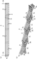
そして、例えば図7に示すように、幅方向に3つのシザーズフレーム4が並ぶようにして幅を大きくするとよい。このシザーズフレーム4を並べる個数は、床部材8の幅と、通過物に必要な橋桁の幅との関係で決めるとよい。
For example, as shown in FIG. 7, the width may be increased by arranging three
さらに、上下に配置される端部の先端ピン挿通孔2dには、それぞれシザーズ式伸縮橋1の幅方向に延びる水平軸2eが連結されている。このことで、伸張方向に隣接される他のフレーム要素3に連結されると共に、適切な間隔で幅方向に長い水平軸2eを用いれば、幅方向に並んで配置されるフレーム要素3を互いに連結して強度の向上を図ることもできる。なお、伸張時に全ての床部材8が平坦となるのが理想であるが、人や車が通過可能な状態をつくり、路面に多少の凹凸があってもよい。例えば、幅方向に一対のシザーズフレーム4を設け、その間隔を自動車のタイヤの幅(車幅)に合わせることで、車両がシザーズフレーム4上を通行可能となっている。なお、連鎖シザーズ6の幅方向のサイズを大きくして複数の普通自動車Cが同時に通過できるようにしてもよく、その場合には、少なくとも普通自動車Cのタイヤの部分にシザーズフレーム4を複数平行に設ければよい。
Furthermore,
シザーズ式伸縮橋1では、このようなフレーム部材2を含むフレーム要素3が設置場所の希望の橋桁の長さとなるように、複数連結されている。図1等に示すように、これらの複数のフレーム部材2よりなるフレーム要素3を含む連鎖シザーズ6の一端が架台フレーム10に固定されている。架台フレーム10は、シザーズ式伸縮橋1の設置面Pに設置されるものであり、側面視L字状に組まれた例えば溶接構造物よりなり、展開時に垂直となる部分にフレーム部材2の伸張方向を定めるレール状のガイド部材11を備えている。詳しくは図示しないが、この上下に延びるガイド部材11内を最も基端側のフレーム部材2に設けたローラ11aが上下に移動し、各フレーム要素3の伸張方向を制御するようになっている。
In the scissors-type expansion bridge 1, a plurality of
架台フレーム10は、伸張方向に長い矩形枠状のベース12に起伏可能に連結されている。具体的には、ベース12の伸張方向基端側に起伏シリンダ13の一端が連結され、この起伏シリンダ13の他端が架台フレーム10に連結されている。架台フレーム10の基端側は、ベース12の回動軸12aに回動可能に連結されている。これにより、起伏シリンダ13の伸縮動作に伴って架台フレーム10がベース12に対して起伏可能となっている。
The
例えばベース12の伸張方向先端側には、架台フレーム10を連結して固定するための固定部18が設けられている。固定部18の有無やその形状は、特に限定されない。
For example, a fixing
シザーズ式伸縮橋1は、連鎖シザーズ6の展開及び収納を補助する展開補助装置23を備えている。具体的には、架台フレーム10の幅方向両側には、展開速度調整手段としてそれぞれ展開速度調整用シリンダ14が設けられており、これらの展開速度調整用シリンダ14が連鎖シザーズ6の展開及び収納を補助するように構成されている。例えば、展開速度調整用シリンダ14の先端には、第1スプロケット15が設けられており、展開速度調整用シリンダ14を伸縮させることで架台フレーム10の下側に固定した第2スプロケット16との間の距離を変更可能となっている。第1スプロケット15及び第2スプロケット16には、展開用チェーン17が掛けられており、この展開用チェーン17の一端が架台フレーム10に固定され、他端が伸張方向基端側から2番目のフレーム部材2の先端に連結されている。
The scissors-type expansion bridge 1 includes a
また、展開補助装置23は、例えば1本の展開用シリンダ19を備えている。展開用シリンダ19のシリンダチューブがベース12に固定され、ロッド先端には、垂直に延びるアーム19aが突設されている。このアーム19aが、展開用シリンダ19の縮小時に例えば伸張方向基端側から2番目の水平軸2eを伸張方向に押し出すことで、連鎖シザーズ6の伸張が開始される。その後は、自重により連鎖シザーズ6が展開されるようになっている。
Further, the
自重による伸張時には、展開用チェーン17が引っ張られ、展開速度調整用シリンダ14が伸張してシザーズフレーム4が開くのを許容する。このときの展開速度調整用シリンダ14からの作動油の流量を図示しない油圧機器で制御することで、展開速度が調整されるようになっている(いわゆるメータアウト制御)。なお、収納時には、展開速度調整用シリンダ14に作動油を送り込んで強制的に縮小させて展開用チェーン17を引きつけて開いたフレーム部材2を閉じるようにしてもよい。展開用チェーン17の掛け数を調整することで、展開速度調整用シリンダ14のストロークが制限されている場合でも、展開用チェーン17の進む速さや距離を調整することができる。
During expansion due to its own weight, the
例えば、起伏シリンダ13、展開速度調整用シリンダ14及び展開用シリンダ19の油圧源として、例えば図示しない電動の油圧ユニットを別途用意すればよい。
For example, an electric hydraulic unit (not shown) may be separately prepared as a hydraulic source for the
そして、架台フレーム10の上端には、展開用シーブ20が設けられ、設置面Pに載置した手動式ウインチ21のワイヤー22が展開用シーブ20に掛けられ、このワイヤー22の先端が伸張方向最先端のフレーム部材2の一端に連結されている。例えば、連鎖シザーズ6の自重で伸張が行われるような場合、手動式ウインチ21を繰り出すことによっても、連鎖シザーズ6の自重による展開速度を調整できるので、展開速度調整手段として用いることもできる。手動式ウインチ21は、油圧式や電動式で構成してもよいが、手動式であれば、人力でも展開できる点で有利である。電動式ウインチであれば、車のバッテリを利用することもできる。
A
次に、実施形態のシザーズ式伸縮橋1の作動について説明する。 Next, the operation of the scissors type expansion bridge 1 of the embodiment will be described.
まず、図2に示す収納状態では、架台フレーム10がベース12の伸張方向基端側に固定されている。起伏シリンダ13、展開速度調整用シリンダ14及び展開用シリンダ19は、縮小状態である。これらを縮小状態に保つことで、収納状態を維持可能に構成することもできる。なお、別途収納状態を維持するためのロック装置が設けられていてもよい。このコンパクトに収容された状態で、トレーラ、船舶、大型ヘリコプター等で運搬が可能となる。
First, in the storage state shown in FIG. 2, the
次いで、別途用意した油圧ユニットを起伏シリンダ13、展開速度調整用シリンダ14及び展開用シリンダ19に連結する。
Next, a separately prepared hydraulic unit is connected to the
次いで、起伏シリンダ13を徐々に伸張させ、図3に示すように、架台フレーム10を起立させる。この状態では、連鎖シザーズ6は縮小されたままである。
Next, the hoisting
次いで、展開用シリンダ19に作動油を送り込んで徐々に伸張させる。すると、展開用シリンダ19のアーム19aによって幅方向に延びる水平軸2eが強制的にスライド移動されると共に、展開用チェーン17が繰り出される。同時に、手動式ウインチ21からワイヤー22が繰り出される。展開速度調整用シリンダ14のチューブロッド側から吐出される作動油の量を調整することで、展開速度が制御される。これにより、全てのフレーム部材2間の間隔が徐々に広がる。このようにして、シザーズフレーム4が一気に広がることなく安定して徐々に延びていく。
Next, hydraulic oil is fed into the developing
そして、図5に示すように、支持用切欠部7aと被支持用切欠7bとが当接して平坦になると伸張が停止し安定する。この状態で、安定させるために何らかのロック手段を設けてもよいし、伸張後の床部材8の上面に板状の部材を載置してボルト等によって強固に一体化してもよい。そのようにして仮設橋が形成される。これにより、床部材8が安定した橋桁となり、普通自動車や人が通行可能となる。このため、災害時に災害現場に持ち込んで橋を迅速に復旧させることができる。
Then, as shown in FIG. 5, when the
逆に収納時には、例えば手動式ウインチ21を手動で巻き取り、又は展開速度調整用シリンダ14を強制的に縮小させながら、床部材8をシザーズフレーム4と共に折り畳めばよく、展開及び収納が容易であり、撤去も極めて容易である。このような手動式ウインチ21を用いれば、人力でも展開及び収納を行える。
On the other hand, when retracting, for example, the
本実施形態では、フレーム部材2は、アルミニウム合金、マグネシウム合金等よりなる軽量且つ剛性の高い構造であるため、運搬が容易であると共に、強度確保も容易である。
In the present embodiment, the
本実施形態では、シザーズフレーム4を完全に伸張させたときにフレーム部材2の上面が平坦となるので、床版部材を別に設けなくても、安定し、フレーム部材2の上面を床版と同じ役割を有するような版を兼ね、その上を人や車が通行することができる。シザーズ式伸縮橋が床版部材を含まないので、床版部材を含むときのような水平な状態から起立させて収納するときに大きな力が必要とならない。また、床版部材を含まないため、部品点数が減って構造が簡単になると共に、軽量化を図ることができる。
In the present embodiment, since the upper surface of the
シザーズフレーム4が奥側に向かって複数並べられることにより、シザーズフレーム4の伸張時に橋桁となるようにしたので、橋桁として使用するときに幅方向の距離を容易に稼ぐことができる。
By arranging a plurality of scissors frames 4 toward the back side, the
したがって、本実施形態に係るシザーズ式伸縮橋1によると、シザーズフレーム4を伸張させた状態でその上面が平坦になるようにしたので、簡単な構造で、運搬、収納及び展開が容易で展開時には安定した構造となるシザーズ式伸縮橋1を得ることができる。
Therefore, according to the scissors-type expansion bridge 1 according to the present embodiment, the top surface of the
本実施形態のシザーズ式伸縮橋1は、予め工場等で製作されるので品質と完成度が高く、コンパクトに折り畳むことができるので、運搬等が極めて容易である。 Since the scissors-type expansion bridge 1 of this embodiment is manufactured in advance in a factory or the like, it has high quality and completeness, and can be folded compactly, so that it is very easy to transport.
また、災害現場での困難な復旧施工にも対応策の選択肢を増やすことができ、現場適合性を向上させることができる。 In addition, it is possible to increase the options of countermeasures for difficult restoration work at the disaster site, and to improve the site suitability.
また、老朽化してきた橋の寿命を延命的に修理する際に、通常、主桁等の主構部の大掛かり補修工事では、橋が通行止となって問題となる。しかし、本実施形態の連鎖シザーズ6を有するシザーズ式伸縮橋1を用いれば、車両制限を行った上で、橋本体の伸縮構造体を利用して橋脚又は橋台上の反力が取れる箇所にて固定し、橋を暫定的に補強することによって、老朽化した橋の負担を緩和することができると共に、その橋の補修も同時に行える利点が生まれる。
In addition, when repairing the life of an aging bridge in a life-prolonging manner, a large-scale repair work for a main structure such as a main girder usually becomes a problem because the bridge is closed. However, if the scissors-type telescopic bridge 1 having the
また、漁港や港湾の桟橋に本実施形態を利用する価値は大きい。つまり、桟橋利用の制限、台風、高潮等による損傷を避けることができ、橋を利用するときだけに架設できることは管理者や利用者にとって利便性がある。 In addition, the use of this embodiment for fishing ports and harbor piers is of great value. In other words, it is convenient for managers and users that it is possible to avoid damage due to pier use restrictions, typhoons, storm surges, etc., and that it can be installed only when using the bridge.
さらに、中低層ビル火災等で避難路を確保する場合に、隣のビルまでに避難橋が架けられるように本実施形態を備えていれば、非常時にその効果は大きい。 Furthermore, when an evacuation route is secured due to a fire in a mid-to-low-rise building, if the present embodiment is provided so that an evacuation bridge can be built up to an adjacent building, the effect is great in an emergency.
−変形例1−
図8は、実施形態の変形例1に係るシザーズ式伸縮橋101の吊橋130による展開例の概略を示す正面図である。なお、以下の各変形例では、図1〜図7と同じ部分については同じ符号を付してその詳細な説明は省略する。-Modification 1-
FIG. 8 is a front view illustrating an outline of a development example of the scissor-type
本変形例では、例えば連鎖シザーズ6の一端側を一方の吊橋130に固定しておき、他端に設けた展開用シーブ120にワイヤー122を掛け、その先端側を他方の吊橋130の展開用シーブ120に掛け、先端をクレーンやウインチで引っ張ることで連鎖シザーズ6が伸張し、その他端側を他方の吊橋130に固定すれば、シザーズ式伸縮橋101が仮設される。
In this modification, for example, one end side of the
なお、他方の吊橋130の展開用シーブ120にワイヤー122を掛けずに直接クレーン等でワイヤー22を引っ張ってもよい。
Note that the
このように構成すれば、これまで現場で問題であった本体の仮組立や橋の長さ分の仮設ヤードは必要なく、押出し工法等による特殊な装置や慎重なバランスを保持することなく、クレーンで短時間に橋の主要な本体を架設することが可能である。 With this configuration, there is no need for temporary assembly of the main body or a temporary yard for the length of the bridge, which has been a problem in the field so far. It is possible to build the main body of the bridge in a short time.
−変形例2−
図9は、実施形態の変形例2に係るポンツーン230によるシザーズ式伸縮橋201の展開例の概略を示し、(a)が収納時の正面図であり、(b)が最大伸張時の正面図である。-Modification 2-
FIG. 9: shows the outline of the expansion example of the scissors-type expansion-
シザーズフレーム4の下端側が複数のポンツーン230(底が平らな舟であり、平底舟、橋脚舟ともいう)に支持され、伸張時に隣接するポンツーン230間の距離を広げることで連鎖シザーズ6が伸張される。
The lower end side of the
本変形例では、図9(a)のように、ポンツーン230を連結して水面231上をタグボートなどで曳航し、現場でポンツーン230に連鎖シザーズ6の下端を支持した状態で、ポンツーン230間の距離を広げて床部材8を水平にして連結すれば、図9(b)のように水面231上に仮設橋を容易に設置することができる。このとき、橋脚は不要である。
In this modified example, as shown in FIG. 9A, the
このように、複数のポンツーン230間を、連鎖シザーズ6で連鎖して容易に河川又は港湾に渡橋システムを構築することも可能となる。いくつかのポンツーン230をコンパクトに集約させることによって、それ自体大きな舟橋システムを容易に構築できる。このシステムで大規模洪水での避難路の確保も可能である。
In this way, it is possible to easily construct a bridge system in a river or a port by linking a plurality of
本変形例の応用として、船上から着岸の目的で「渡し」が必要な場合(特に、港湾施設も大きく被災した震災を想定した場合)に、船上にコンパクトな連鎖シザーズ6が装備されていると、機動的な運用が可能となるとともに、船から別の船に移動する場合にも、安全に渡ることが可能となる。
As an application of this modified example, when “passing” is necessary for the purpose of berthing from the ship (particularly assuming that the harbor facilities are also severely damaged), the
−変形例3−
図10は、実施形態の変形例3に係るトレーラ330の荷台331上にシザーズ式伸縮橋1を設けた状態を示す正面図である。-Modification 3-
FIG. 10 is a front view illustrating a state in which the scissors-type expansion bridge 1 is provided on the
本変形例では、架台フレーム10を含むベース12が、トレーラ330の荷台331に載置されている。この荷台331を現場までトレーラ330で運んで現地でシザーズ式伸縮橋1を降ろして連鎖シザーズ6が伸張される。
In this modification, the base 12 including the
具体的には、収納状態のシザーズ式伸縮橋1をトレーラ330の荷台331に積んで運搬し、現場でアウトリガー332を伸張して上昇させた後、トレーラ330を前進させることで、シザーズ式伸縮橋1を地面等に載置可能である。
Specifically, the scissors-type telescopic bridge 1 in the stowed state is loaded and transported on the
載置後は、アウトリガー332を伸張させた状態で連鎖シザーズ6を伸張させてもよいし、アウトリガー332を縮めて展開させてもよい。このように、現場でアウトリガー332を用いて荷台を地面等に載置した後、展開することにより、仮設橋等を極めて迅速且つ容易に設けることができる。
After placement, the
逆に撤収するときには、連鎖シザーズ6を縮小後、アウトリガー332で上昇させた状態でその下にトレーラ330の荷台331を挿入し、アウトリガー332を縮めることで、クレーンで吊り上げることなく、荷台331に載せて撤収することができる。
On the other hand, when the
本変形例では、アウトリガー332を用いることで、クレーンなどの特別な機械を用意しなくても、シザーズ式伸縮橋1の積み込み及び積み降ろしを極めて容易に行うことができる。
In this modification, by using the
−変形例4−
詳しくは図示しないが、片持ち状態で自立展開できるシザーズ式伸縮橋1を両岸から張り出し、その中央においてベントなどでサポートさせ、双方の連鎖シザーズ6を中央で結合した後、ベントなどのサポートを除去することによって、所望の橋を素早く構築することができる。-Modification 4-
Although not shown in detail, the scissors-type expansion bridge 1 that can be deployed independently in a cantilever state is projected from both banks and supported by a vent or the like in the center, and both chained
−変形例5−
詳しくは図示しないが、シザーズ式伸縮橋1を複数の柱となるベントから所定のスパンの両張出し状態で展開させ、両方向からの連鎖シザーズ6を結合し、ベントのサポートを除去することによって、所望の橋を素早く構築してもよい。-Modification 5-
Although not shown in detail, the scissors-type expansion bridge 1 is deployed in a state where both ends of a predetermined span are extended from a plurality of columns of vents, the chained
(その他の実施形態)
本発明は、上記実施形態について、以下のような構成としてもよい。(Other embodiments)
The present invention may be configured as follows with respect to the above embodiment.
すなわち、上記実施形態では、展開補助装置23として、展開用チェーン17を利用した展開速度調整用シリンダ14について説明したが、特に小型のシザーズ式伸縮橋1であれば、展開用チェーン17及び展開速度調整用シリンダ14を設けずに、手動式ウインチ21のみで展開及び収納を行うこともできる。
That is, in the above-described embodiment, the deployment
また、伸張方向先端側の水平軸2eに車輪を設ければ、連鎖シザーズ6をスムーズに展開できてよい。
Further, if a wheel is provided on the
なお、以上の実施形態は、本質的に好ましい例示であって、本発明、その適用物や用途の範囲を制限することを意図するものではない。 In addition, the above embodiment is an essentially preferable illustration, Comprising: It does not intend restrict | limiting the range of this invention, its application thing, or a use.
以上説明したように、本発明は、シザーズ式伸縮橋などのシザーズ式伸縮構造について有用である。 As described above, the present invention is useful for scissors-type stretchable structures such as scissors-type stretchable bridges.
1 シザーズ式伸縮橋(シザーズ式伸縮構造)
2 フレーム部材
2a 中央ピン挿通孔
2b 貫通孔
2c 中心軸
2d 先端ピン挿通孔
2e 水平軸
3 フレーム要素
4 シザーズフレーム
5a ヒンジ部
6 連鎖シザーズ
7 シザーズ本体
8 床部材
10 架台フレーム
11 ガイド部材
11a ローラ
12 ベース
12a 回動軸
13 起伏シリンダ
14 展開速度調整用シリンダ
15 第1スプロケット
16 第2スプロケット
17 展開用チェーン
18 固定部
19 展開用シリンダ
19a アーム
20 展開用シーブ
21 手動式ウインチ
22 ワイヤー
23 展開補助装置
101 シザーズ式伸縮橋(シザーズ式伸縮構造)
120 展開用シーブ
122 ワイヤー
130 橋
201 シザーズ式伸縮橋(シザーズ式伸縮構造)
230 ポンツーン
231 水面
330 トレーラ
331 荷台
332 アウトリガー1 Scissors-type expansion bridge (scissors-type expansion structure)
2 Frame members
2a Center pin insertion hole
2b Through hole
2c Center axis
2d Tip pin insertion hole
2e Horizontal axis
3 Frame elements
4 Scissors frame
5a Hinge part
6 Chain Scissors
7 Scissors body
8 Floor material
10 Mounting frame
11 Guide members
11a Roller
12 base
12a Rotating shaft
13 Undulating cylinder
14 Cylinder for deployment speed adjustment
15 First sprocket
16 Second sprocket
17 Chain for deployment
18 Fixed part
19 Cylinder for deployment
19a arm
20 Sheave for deployment
21 Manual winch
22 wires
23
120 Sheaves for
230
Claims (6)
中央部分で互いにピン結合された2本のフレーム部材を含むフレーム要素が複数個該フレーム部材の先端部で互いにピン結合されたシザーズフレームを有し、
上記シザーズフレームの伸張時において、上記フレーム要素における手前側の上記フレーム部材が直線状にそれぞれ互いに連結されると共に、奥側の上記フレーム部材が直線状にそれぞれ互いに連結されることにより、上記フレーム部材の上面が連続した平坦面が形成される
ことを特徴とするシザーズ式伸縮構造。It is a scissors-type elastic structure that can expand and contract in the extension direction,
A plurality of frame elements including two frame members that are pin-coupled to each other at the central portion have a scissor frame that is pin-coupled to each other at the tip of the frame member;
When the scissor frame is extended, the frame members on the front side of the frame element are linearly connected to each other, and the frame members on the back side are linearly connected to each other, whereby the frame member A scissors-type elastic structure characterized in that a flat surface having a continuous upper surface is formed.
上記シザーズフレームが奥側に向かって複数並べられることにより、上記シザーズフレームの伸張時に橋桁となる
ことを特徴とするシザーズ式伸縮構造。In the scissors type elastic structure according to claim 1,
A scissors-type telescopic structure, wherein a plurality of scissors frames are arranged toward the back side to form bridge girders when the scissors frame is extended.
フレーム部材は、中央部分に設けた中央ピン挿通孔を有するシザーズ本体と、該シザーズ本体の上側に設けられ、上記平坦面を形成する床部材とを備えている
ことを特徴とするシザーズ式伸縮構造。In the scissors type elastic structure according to claim 1 or 2,
A scissors-type telescopic structure characterized in that the frame member includes a scissors body having a central pin insertion hole provided in a central portion, and a floor member provided above the scissors body and forming the flat surface. .
上記伸張時のシザーズフレームは、平面視で互いのフレーム部材の接続する箇所が、手前側と奥側とでずれている
ことを特徴とするシザーズ式伸縮構造。In the scissors type expansion-contraction structure as described in any one of Claims 1 thru | or 3,
The scissors frame at the time of expansion is a scissors-type stretchable structure characterized in that the positions where the frame members are connected to each other are shifted between the front side and the back side in plan view.
上記シザーズフレームの下端側が複数のポンツーンに支持され、伸張時に隣接するポンツーン間の距離を広げることで伸張される
ことを特徴とするシザーズ式伸縮構造。In the scissors type expansion-contraction structure as described in any one of Claims 1 thru | or 4,
A scissors-type telescopic structure, wherein a lower end side of the scissors frame is supported by a plurality of pontoons and is expanded by increasing a distance between adjacent pontoons during expansion.
トレーラの荷台に載置可能であると共に、該荷台の外側で上下方向に延びて自重を支えるアウトリガーを備えている
ことを特徴とするシザーズ式伸縮構造。In the scissors type expansion-contraction structure as described in any one of Claims 1 thru | or 4,
A scissors-type telescopic structure characterized by comprising an outrigger that can be placed on a trailer bed and that extends up and down outside the bed to support its own weight.
Applications Claiming Priority (1)
| Application Number | Priority Date | Filing Date | Title |
|---|---|---|---|
| PCT/JP2014/003252 WO2015193930A1 (en) | 2014-06-17 | 2014-06-17 | Scissors-type retractable structure |
Publications (2)
| Publication Number | Publication Date |
|---|---|
| JP6068681B2 true JP6068681B2 (en) | 2017-01-25 |
| JPWO2015193930A1 JPWO2015193930A1 (en) | 2017-04-20 |
Family
ID=54934967
Family Applications (1)
| Application Number | Title | Priority Date | Filing Date |
|---|---|---|---|
| JP2015556302A Expired - Fee Related JP6068681B2 (en) | 2014-06-17 | 2014-06-17 | Scissor-type telescopic structure |
Country Status (5)
| Country | Link |
|---|---|
| EP (1) | EP3147407B1 (en) |
| JP (1) | JP6068681B2 (en) |
| CN (1) | CN105473789B (en) |
| PL (1) | PL3147407T3 (en) |
| WO (1) | WO2015193930A1 (en) |
Families Citing this family (4)
| Publication number | Priority date | Publication date | Assignee | Title |
|---|---|---|---|---|
| CN107905087A (en) * | 2017-12-22 | 2018-04-13 | 贵州省水利水电勘测设计研究院 | A kind of collapsible access bridge for water inlet |
| RU2687662C1 (en) * | 2018-07-19 | 2019-05-15 | Общество с ограниченной ответственностью "Несущие системы" | Extendable truss of cantilever span of alternate overhang |
| CN112160229A (en) * | 2020-10-21 | 2021-01-01 | 东南大学 | Emergency expandable cable-stayed bridge and self-erecting construction method thereof |
| CN117051729B (en) * | 2023-08-18 | 2024-05-17 | 西安公路研究院有限公司 | Emergency repair erection device and method for reinforced concrete combined bridge |
Citations (6)
| Publication number | Priority date | Publication date | Assignee | Title |
|---|---|---|---|---|
| JPS4829377Y1 (en) * | 1969-09-24 | 1973-09-06 | ||
| JPS6462600A (en) * | 1987-09-01 | 1989-03-09 | Zenya Kaiyo Service Kk | Expansible transfer bridge |
| JP2007107369A (en) * | 2005-09-14 | 2007-04-26 | Hiroshima Univ | Structural body and extension/contraction device for its main frame |
| US20080010912A1 (en) * | 2002-06-25 | 2008-01-17 | Hanson Stuart C | Extendable support structures |
| JP2011256586A (en) * | 2010-06-08 | 2011-12-22 | Hoshikei Kinzokukogyo Co Ltd | Structure |
| JP2014145203A (en) * | 2013-01-29 | 2014-08-14 | Hiroshima Univ | Scissors type expansion structure |
Family Cites Families (6)
| Publication number | Priority date | Publication date | Assignee | Title |
|---|---|---|---|---|
| GB1068155A (en) * | 1963-07-02 | 1967-05-10 | Sydney Howell | Structural members |
| PT78869A (en) * | 1984-07-09 | 1984-08-01 | Luis Gonzaga De Morais Zoio | Joined frame |
| DE19747108A1 (en) * | 1997-10-24 | 1999-04-29 | Univ Magdeburg Tech | Flap bridge folding device |
| FR2945298B1 (en) * | 2009-05-06 | 2011-06-17 | Deschamps A & Fils Ets | PERFECTLY TEMPORARY BRIDGE |
| CN203514172U (en) * | 2013-10-21 | 2014-04-02 | 贾针 | Emergency rescue device |
| CN103835220B (en) * | 2014-03-06 | 2016-09-07 | 南京工业大学 | Quick deployable formula prestressing force steel bridge |
-
2014
- 2014-06-17 CN CN201480039964.5A patent/CN105473789B/en not_active Expired - Fee Related
- 2014-06-17 PL PL14895015T patent/PL3147407T3/en unknown
- 2014-06-17 JP JP2015556302A patent/JP6068681B2/en not_active Expired - Fee Related
- 2014-06-17 WO PCT/JP2014/003252 patent/WO2015193930A1/en active Application Filing
- 2014-06-17 EP EP14895015.7A patent/EP3147407B1/en active Active
Patent Citations (6)
| Publication number | Priority date | Publication date | Assignee | Title |
|---|---|---|---|---|
| JPS4829377Y1 (en) * | 1969-09-24 | 1973-09-06 | ||
| JPS6462600A (en) * | 1987-09-01 | 1989-03-09 | Zenya Kaiyo Service Kk | Expansible transfer bridge |
| US20080010912A1 (en) * | 2002-06-25 | 2008-01-17 | Hanson Stuart C | Extendable support structures |
| JP2007107369A (en) * | 2005-09-14 | 2007-04-26 | Hiroshima Univ | Structural body and extension/contraction device for its main frame |
| JP2011256586A (en) * | 2010-06-08 | 2011-12-22 | Hoshikei Kinzokukogyo Co Ltd | Structure |
| JP2014145203A (en) * | 2013-01-29 | 2014-08-14 | Hiroshima Univ | Scissors type expansion structure |
Also Published As
| Publication number | Publication date |
|---|---|
| PL3147407T3 (en) | 2020-01-31 |
| EP3147407B1 (en) | 2019-08-07 |
| CN105473789A (en) | 2016-04-06 |
| EP3147407A1 (en) | 2017-03-29 |
| JPWO2015193930A1 (en) | 2017-04-20 |
| EP3147407A4 (en) | 2017-06-07 |
| CN105473789B (en) | 2017-03-15 |
| WO2015193930A1 (en) | 2015-12-23 |
Similar Documents
| Publication | Publication Date | Title |
|---|---|---|
| JP2014145203A (en) | Scissors type expansion structure | |
| JP5297624B2 (en) | Self-propelled lift crane equipped with variable position counterweight unit and its operating method | |
| JP5736366B2 (en) | Improved temporary bridge | |
| JP6068681B2 (en) | Scissor-type telescopic structure | |
| JP5475960B2 (en) | Mast raising structure and process for high capacity mobile lift crane | |
| RU2532204C2 (en) | Lifting crane guys expander and method of its adjustment | |
| JP2012526213A5 (en) | ||
| JP2023164950A (en) | Heavy object movement device and heavy object movement method using the heavy object movement device | |
| US6698371B1 (en) | Boat with personnel elevator apparatus | |
| JP2009007164A (en) | Self-traveling lift crane having variable position counterweight | |
| JP2009007164A5 (en) | ||
| US4628560A (en) | Expandable portable bridge structure | |
| JP3343817B2 (en) | Hoisting device | |
| JP6235854B2 (en) | Crane assembly method | |
| US7686174B2 (en) | Vehicle crane with a telescopic boom, as well as process for assembling and disassembling the anchor supports of the telescopic boom | |
| JP2022130029A (en) | Floor slab lifting device and installation method of floor slab lifting device | |
| US4609204A (en) | Extension for outrigger beam | |
| JP4770417B2 (en) | Construction machinery platform | |
| JP7447663B2 (en) | Crane assembly method | |
| CN115258065A (en) | Inflatable overwater operation platform | |
| JP6569768B2 (en) | Mobile crane | |
| JPH07292619A (en) | Floating bridge and lifting device therefor | |
| JP6428714B2 (en) | Mobile crane | |
| WO2013014620A1 (en) | A crane | |
| WO2023105982A1 (en) | Crane |
Legal Events
| Date | Code | Title | Description |
|---|---|---|---|
| TRDD | Decision of grant or rejection written | ||
| A01 | Written decision to grant a patent or to grant a registration (utility model) |
Free format text: JAPANESE INTERMEDIATE CODE: A01 Effective date: 20161206 |
|
| A61 | First payment of annual fees (during grant procedure) |
Free format text: JAPANESE INTERMEDIATE CODE: A61 Effective date: 20161222 |
|
| R150 | Certificate of patent or registration of utility model |
Ref document number: 6068681 Country of ref document: JP Free format text: JAPANESE INTERMEDIATE CODE: R150 |
|
| R250 | Receipt of annual fees |
Free format text: JAPANESE INTERMEDIATE CODE: R250 |
|
| R250 | Receipt of annual fees |
Free format text: JAPANESE INTERMEDIATE CODE: R250 |
|
| R250 | Receipt of annual fees |
Free format text: JAPANESE INTERMEDIATE CODE: R250 |
|
| R250 | Receipt of annual fees |
Free format text: JAPANESE INTERMEDIATE CODE: R250 |
|
| LAPS | Cancellation because of no payment of annual fees |