JP2009007164A - Self-traveling lift crane having variable position counterweight - Google Patents
Self-traveling lift crane having variable position counterweight Download PDFInfo
- Publication number
- JP2009007164A JP2009007164A JP2008077842A JP2008077842A JP2009007164A JP 2009007164 A JP2009007164 A JP 2009007164A JP 2008077842 A JP2008077842 A JP 2008077842A JP 2008077842 A JP2008077842 A JP 2008077842A JP 2009007164 A JP2009007164 A JP 2009007164A
- Authority
- JP
- Japan
- Prior art keywords
- counterweight
- rack
- self
- crane
- lift crane
- Prior art date
- Legal status (The legal status is an assumption and is not a legal conclusion. Google has not performed a legal analysis and makes no representation as to the accuracy of the status listed.)
- Granted
Links
Images


Classifications
-
- B—PERFORMING OPERATIONS; TRANSPORTING
- B66—HOISTING; LIFTING; HAULING
- B66C—CRANES; LOAD-ENGAGING ELEMENTS OR DEVICES FOR CRANES, CAPSTANS, WINCHES, OR TACKLES
- B66C23/00—Cranes comprising essentially a beam, boom, or triangular structure acting as a cantilever and mounted for translatory of swinging movements in vertical or horizontal planes or a combination of such movements, e.g. jib-cranes, derricks, tower cranes
- B66C23/18—Cranes comprising essentially a beam, boom, or triangular structure acting as a cantilever and mounted for translatory of swinging movements in vertical or horizontal planes or a combination of such movements, e.g. jib-cranes, derricks, tower cranes specially adapted for use in particular purposes
- B66C23/36—Cranes comprising essentially a beam, boom, or triangular structure acting as a cantilever and mounted for translatory of swinging movements in vertical or horizontal planes or a combination of such movements, e.g. jib-cranes, derricks, tower cranes specially adapted for use in particular purposes mounted on road or rail vehicles; Manually-movable jib-cranes for use in workshops; Floating cranes
- B66C23/46—Mobile jib-cranes with non-slewable jibs
-
- B—PERFORMING OPERATIONS; TRANSPORTING
- B66—HOISTING; LIFTING; HAULING
- B66C—CRANES; LOAD-ENGAGING ELEMENTS OR DEVICES FOR CRANES, CAPSTANS, WINCHES, OR TACKLES
- B66C23/00—Cranes comprising essentially a beam, boom, or triangular structure acting as a cantilever and mounted for translatory of swinging movements in vertical or horizontal planes or a combination of such movements, e.g. jib-cranes, derricks, tower cranes
- B66C23/62—Constructional features or details
- B66C23/72—Counterweights or supports for balancing lifting couples
- B66C23/74—Counterweights or supports for balancing lifting couples separate from jib
- B66C23/76—Counterweights or supports for balancing lifting couples separate from jib and movable to take account of variations of load or of variations of length of jib
-
- F—MECHANICAL ENGINEERING; LIGHTING; HEATING; WEAPONS; BLASTING
- F16—ENGINEERING ELEMENTS AND UNITS; GENERAL MEASURES FOR PRODUCING AND MAINTAINING EFFECTIVE FUNCTIONING OF MACHINES OR INSTALLATIONS; THERMAL INSULATION IN GENERAL
- F16H—GEARING
- F16H19/00—Gearings comprising essentially only toothed gears or friction members and not capable of conveying indefinitely-continuing rotary motion
- F16H19/02—Gearings comprising essentially only toothed gears or friction members and not capable of conveying indefinitely-continuing rotary motion for interconverting rotary or oscillating motion and reciprocating motion
- F16H19/04—Gearings comprising essentially only toothed gears or friction members and not capable of conveying indefinitely-continuing rotary motion for interconverting rotary or oscillating motion and reciprocating motion comprising a rack
Abstract
Description
本出願は、2006年10月27日出願の米国特許仮出願第60/863,265号の35U.S.C.119(e)に基づく恩典を請求する、2007年4月9日出願の米国特許出願第11/733,104号の一部継続出願であり、両出願を参考文献としてここに援用する。 This application is filed on 35 U.S. of US Provisional Application No. 60 / 863,265 filed Oct. 27, 2006. S. C. 119 (e) is a continuation-in-part of US patent application Ser. No. 11 / 733,104 filed Apr. 9, 2007, claiming benefit under 119 (e), both applications incorporated herein by reference.
本出願は、リフトクレーンに、特に、クレーンに掛かる吊り荷の平衡を保つために異なる位置に動かすことのできるカウンタウエイトを有している自走式リフトクレーンに関する。 The present application relates to lift cranes, and more particularly to self-propelled lift cranes having counterweights that can be moved to different positions to balance the load on the crane.
リフトクレーンは、クレーンが吊り荷を持ち上げる際にクレーンの平衡を保つためのカウンタウエイトを通常備えている。クレーン後方のカウンタウエイトが非常に大きいため、吊り荷を吊り上げていない時に後向きに転倒するのを防止するためのカウンタウエイトを車体に装備することもある。その上、自走式リフトクレーンのリフト容量を更に強化するために、カウンタウエイトトレーラのような予備のカウンタウエイト用付属装置が、クレーンに追加されることもある。吊り荷は、クレーンの旋回中心に対して頻繁に内外に動かされ、従って、引き上げ、移動、及び設置作業中に種々のモーメントが発生するため、予備のカウンタウエイト用付属装置も含め、カウンタウエイトをクレーンの旋回中心に対して前後に動かせれば好都合である。この様にすれば、カウンタウエイトを決まった距離に保たなければならない場合に必要となる量より少ない量のカウンタウエイトを使用できるようになる。 Lift cranes are usually equipped with counterweights to keep the crane in balance when the crane lifts a suspended load. Since the counterweight behind the crane is very large, the vehicle body may be equipped with a counterweight for preventing the vehicle from falling backward when the suspended load is not lifted. In addition, extra counterweight attachments, such as counterweight trailers, may be added to the crane to further enhance the lift capacity of the self-propelled lift crane. Suspended loads are frequently moved in and out with respect to the center of rotation of the crane, and therefore various moments are generated during lifting, moving, and installation operations. It is advantageous if the crane can be moved back and forth with respect to the pivot center of the crane. In this way, a smaller amount of counterweight can be used than would be necessary if the counterweight had to be kept at a fixed distance.
クレーンは自走式である必要があるため、全ての他のカウンタウエイト用付属装置も移動できる必要がある。しかしながらフックに吊り荷が掛かっていないときは、それらの予備のカウンタウエイトは、通常メインクレーンから切り離して地上に置かれ、そうしなければ、クレーンを後ろ方に転倒させるモーメントが発生することになる。従って、フックに吊り荷が掛かっていない状態でクレーンを移動させる必要がある場合は、予備のカウンタウエイト用付属装置も地上を移動できなければならない。つまり、予備のカウンタウエイトユニットの旋回又は移動のために、地面は、整備して障害物のない状態にする必要があり、そしてしばしば坑木を所定の位置に設置しなければならない。 Since the crane needs to be self-propelled, all other counterweight attachments must also be movable. However, when there is no load on the hook, these spare counterweights are usually separated from the main crane and placed on the ground, otherwise there will be moments that cause the crane to fall backwards. . Therefore, if it is necessary to move the crane with no hanging load on the hook, the auxiliary counterweight attachment device must also be able to move on the ground. That is, for the swiveling or movement of the spare counterweight unit, the ground needs to be serviced and clear of obstacles, and often the timber must be installed in place.
前述の代表的な実例は、Superlift付属装置付きTerex Demag CC8800クレーンである。このクレーンは、100メートルトンの車体カウンタウエイト、280メートルトンのクレーンカウンタウエイト、及び640メートルトンの予備のカウンタウエイト用付属装置、つまり合計で1020メートルトンのカウンタウエイトを含んでいる。予備のカウンタウエイトは、伸縮部材によって内外に動かせる。このクレーンは、23,500メートルトンメートルの最大定格負荷モーメントを有している。この様に、最大定格負荷モーメント対カウンタウエイトの合計重量の比率は23.04しかない。 A representative example of the foregoing is a Terex Demag CC8800 crane with Superlift attachment. The crane includes a 100 metric ton body counterweight, a 280 metric ton crane counterweight, and a 640 metric ton auxiliary counterweight attachment, that is, a total of 1020 metric ton counterweights. The spare counterweight can be moved in and out by an elastic member. This crane has a maximum rated load moment of 23,500 metric tons. Thus, the ratio of the maximum rated load moment to the total weight of the counterweight is only 23.04.
これら全てのカウンタウエイトによって重い吊り荷を持ち上げることができるようになるが、クレーンを新しい仕事の現場に移動するために撤去する時には必ずカウンタウエイトも運搬しなければならない。米国の高速道路規制では、300メートルトンのカウンタウエイトを運搬するには15台のトラックが必要である。このため、自走式リフトクレーンには、同じ大きさの吊り荷をより少量のクレーンカウンタウエイトを使って吊り上げることができるようにする更なる改善が必要とされている。
軽減された総カウンタウエイト重量を用いているが、クレーンは自走式で、更に重い総カウンタウエイト重量を使用することで、当該クレーンに匹敵する吊り荷を吊り上げることができる自走式リフトクレーンとその操作方法が発明された。第1の態様では、本発明は、可動地面係合部材を有する車体と、地面係合部材に対し旋回可能となるように車体に回転可能に接続されている旋回体と、旋回体の前側部分に枢動可能に取り付けられているブームと、第1端部が旋回体に取り付けられているマストと、マストと旋回体の後側部分との間に接続されている背面連結部材と、可動式のカウンタウエイトユニットと、少なくとも1つのリニアアクチュエータ装置と、第1端部が旋回体に、第2端部がリニアアクチュエータ装置に枢動可能に接続されている少なくとも1つのアームと、を備えている自走式リフトクレーンである。アームとリニアアクチュエータ装置は、旋回体とカウンタウエイトユニットの間に接続され、リニアアクチュエータ装置を伸縮させると旋回体に対するカウンタウエイトユニットの位置が変わるようになっている。 A reduced total counterweight weight is used, but the crane is self-propelled, and by using a heavier total counterweight weight, a self-propelled lift crane that can lift a suspended load comparable to the crane The method of operation was invented. In a first aspect, the present invention provides a vehicle body having a movable ground engagement member, a swing body that is rotatably connected to the vehicle body so as to be turnable with respect to the ground engagement member, and a front portion of the swing body. A boom pivotably attached to the mast, a mast having a first end attached to the swivel body, a back connecting member connected between the mast and the rear portion of the swivel body, and movable A counterweight unit, at least one linear actuator device, and at least one arm having a first end portion connected to the revolving body and a second end portion pivotally connected to the linear actuator device. It is a self-propelled lift crane. The arm and the linear actuator device are connected between the swing body and the counterweight unit. When the linear actuator device is expanded and contracted, the position of the counterweight unit with respect to the swing body is changed.
第2の態様では、本発明は、可動地面係合部材を有する車体と、地面係合部材に対し旋回可能となるように車体に回転可能に接続されている旋回体と、旋回体の前側部分に枢動可能に取り付けられているブームと、第1端部が、旋回体の旋回面に対して固定した角度で旋回体に取り付けられているマストと、マストの第2端部に接続されている引張部材から吊り下げられている可動式のカウンタウエイトユニットと、カウンタウエイトユニットがマストの最上部より前側の位置に動かされてそこに保持され、そしてマストの最上部より後側の位置に動かされてそこに保持されるように、旋回体とカウンタウエイトユニットの間に接続されているカウンタウエイト移動構造と、を備えている自走式リフトクレーンである。 In a second aspect, the present invention provides a vehicle body having a movable ground engaging member, a swinging body rotatably connected to the vehicle body so as to be turnable with respect to the ground engaging member, and a front portion of the swinging body. A boom that is pivotally attached to the mast, a first end connected to the mast attached to the swivel at a fixed angle with respect to the swivel surface of the swivel, and a second end of the mast A movable counterweight unit suspended from a tension member, and the counterweight unit is moved to a position in front of the top of the mast and held there, and moved to a position in rear of the top of the mast. It is a self-propelled lift crane provided with a counterweight moving structure connected between the swivel body and the counterweight unit so as to be held there.
本発明の第3の態様は、可動地面係合部材を有する車体と、地面係合部材に対し旋回可能となるように、旋回軸を中心に車体に回転可能に接続されている旋回体と、旋回体の前側部分に枢動可能に取り付けられているブームと、第1端部が旋回体に取り付けられているマストと、可動式のカウンタウエイトユニットと、カウンタウエイトユニットが前側の位置と後側の位置の両方に動かされてそこに保持されるように、旋回体とカウンタウエイトユニットの間に接続されているカウンタウエイト移動構造と、を備えており、クレーンは少なくとも総量250メートルトンのカウンタウエイトと少なくとも6250メートルトンメートルの最大定格負荷モーメントを有しており、クレーンの全てのカウンタウエイトの総重量に対する最大定格負荷モーメントは、少なくとも25である、自走式リフトクレーンである。 According to a third aspect of the present invention, there is provided a vehicle body having a movable ground engaging member, a revolving body that is rotatably connected to the vehicle body about a revolving axis so as to be turnable with respect to the ground engaging member, A boom pivotally attached to the front part of the swivel body, a mast whose first end is attached to the swivel body, a movable counterweight unit, and the counterweight unit at the front position and rear side A counterweight moving structure connected between the swivel body and the counterweight unit so that the counterweight is moved to and held in both of the positions of the counterweight, and the crane has a counterweight of at least a total amount of 250 metric tons And a maximum rated load moment of at least 6250 metric tons, with a maximum rated negative for the total weight of all counterweights of the crane Moment is at least 25, it is a self-propelled lift crane.
本発明の第4の態様は、自走式リフトクレーンの操作方法である。リフトクレーンは、可動地面係合部材を有する車体と、地面係合部材に対し旋回可能となるように、車体に回転可能に接続されている旋回体と、旋回体の前側部分に枢動可能に取り付けられており、そこからホイストラインが伸長しているブームと、第1端部が旋回体に取り付けられているマストと、可動式のカウンタウエイトユニットと、を備えている。本方法は、フックに吊り荷が掛けられていない時は、カウンタウエイトをマストの最上部の真下の地点より前方に配置する段階と、ホイストラインが吊り荷を支持している時は、カウンタウエイトをマストの最上部より後方の位置に配置する段階とを備えており、可動式のカウンタウエイトは、クレーンの引き上げ、移動、及び設置作業中には車体の地面係合部材によって間接的に支持される以外は、地面で支持されることはない。 A fourth aspect of the present invention is a method for operating a self-propelled lift crane. The lift crane is capable of pivoting on a vehicle body having a movable ground engaging member, a revolving body rotatably connected to the vehicle body so as to be turnable with respect to the ground engaging member, and a front side portion of the revolving body. A boom having a hoist line extending therefrom, a mast having a first end attached to the swing body, and a movable counterweight unit are provided. The method includes the steps of placing a counterweight forward of a point just below the top of the mast when no load is hung on the hook, and a counterweight when the hoist line supports the load. The movable counterweight is indirectly supported by the ground engaging member of the vehicle body during the crane lifting, moving, and installation operations. It is not supported on the ground except
第5の態様では、本発明は、自走式リフトクレーンの操作方法である。リフトクレーンは、可動地面係合部材を有する車体と、地面係合部材に対し旋回可能となるように、車体に回転可能に接続されている旋回体と、旋回体の前側部分に枢動可能に取り付けられており、そこからホイストラインが伸長しているブームと、第1端部が旋回体に取り付けられているマストと、少なくとも1つのリニアアクチュエータ装置と、可動式のカウンタウエイトユニットと、を備えている。本方法は、吊り荷が掛かった状態で引き上げ、移動、及び設置作業を行う段階を備えており、その際、吊り荷の平衡を保つために、可動式のカウンタウエイトは、引き上げ、移動、及び設置作業中にリニアアクチュエータ装置を伸縮させることによって旋回体の前側の部分に向けて、及びそこから離れる方向に動かされるが、カウンタウエイトは、車体の地面係合部材によって間接的に支持される以外に地面で支持されることはない。 In a fifth aspect, the present invention is a method for operating a self-propelled lift crane. The lift crane is capable of pivoting on a vehicle body having a movable ground engaging member, a revolving body rotatably connected to the vehicle body so as to be turnable with respect to the ground engaging member, and a front side portion of the revolving body. A boom having a hoist line extending therefrom, a mast having a first end attached to the swing body, at least one linear actuator device, and a movable counterweight unit. ing. The method includes the steps of lifting, moving, and installing in a state where a suspended load is applied. In this case, in order to maintain the balance of the suspended load, the movable counterweight is lifted, moved, and During installation, the linear actuator device is expanded and contracted to move toward and away from the front part of the swivel body, except that the counterweight is indirectly supported by the ground engaging member of the vehicle body. Is not supported by the ground.
第6の態様では、本発明は、可動地面係合部材を有する車体と、地面係合部材に対し旋回可能となるように、旋回軸を中心に車体に回転可能に接続されている旋回体と、旋回体の前側部分に枢動可能に取り付けられているブームと、可動式のカウンタウエイトユニットと、カウンタウエイトユニットが前側の位置及び後側の位置に動かされてそこに保持されるように、旋回体とカウンタウエイトユニットの間に接続されているカウンタウエイト移動構造と、を備えており、カウンタウエイト移動構造は、ハウジングとラックとを有するラックアンドピニオンアセンブリを備えており、ラックは、互いに対向する第1及び第2側面と互いに対向する第3及び第4側面とを備えた長方形断面を有しており、且つ第1側面及び第2側面上に歯を有しており、少なくとも第1及び第3ピニオンギアはラックの第1側面上の歯と係合しており、第2及び第4ピニオンギアはラックの第2側面上の歯と係合しており、また、各ピニオンギアは別々の油圧モーターで駆動されており、第1ピニオンギアを駆動するモーターは、ラックの第3ピニオンギアを駆動するモーターとは対向する側に隣接するハウジングの上に取り付けられており、第2ピニオンギアを駆動するモーターは、ラックの第4ピニオンギアを駆動するモーターとは対向する側に隣接するハウジングの上に取り付けられている、自走式リフトクレーンである。
In a sixth aspect, the present invention provides a vehicle body having a movable ground engaging member, and a revolving body that is rotatably connected to the vehicle body about a turning axis so as to be turnable with respect to the ground engaging member. , A boom pivotally attached to the front part of the swivel, a movable counterweight unit, and the counterweight unit moved to a front position and a rear position and held there, A counterweight moving structure connected between the revolving unit and the counterweight unit. The counterweight moving structure includes a rack and pinion assembly having a housing and a rack, and the racks face each other. Having a rectangular cross section with first and second side surfaces and third and fourth side surfaces facing each other, and having teeth on the first and second side surfaces At least the first and third pinion gears are engaged with teeth on the first side of the rack, the second and fourth pinion gears are engaged with teeth on the second side of the rack, and Each pinion gear is driven by a separate hydraulic motor, and the motor that drives the first pinion gear is mounted on the adjacent housing on the side opposite to the motor that drives the third pinion gear of the rack. The motor that drives the second pinion gear is a self-propelled lift crane that is mounted on the housing adjacent to the side opposite to the motor that drives the fourth pinion gear of the rack.
第7の態様では、本発明は、可動地面係合部材を有する車体と、地面係合部材に対し旋回可能となるように車体に回転可能に接続されている旋回体と、旋回体の前側部分に枢動可能に取り付けられており、吊り荷を取り扱うための吊り荷ホイストラインを含んでいるブームと、可動式のカウンタウエイトユニットと、カウンタウエイトユニットが前側の位置と後側の位置の両方に動かされてそこに保持されるように、旋回体とカウンタウエイトユニットの間に接続されているカウンタウエイト移動構造と、吊り荷が突然離れたような場合にカウンタウエイトを支持できる少なくとも2つの地面係合部材を含むカウンタウエイトユニットに取り付けられているカウンタウエイト支持構造であって、地面係合部材の間の距離が少なくとも第1及び第2位置の間で調整できるように地面係合部材の間に接続されている伸縮自在構造を備えているカウンタウエイト支持構造と、を備えている、自走式リフトクレーンである。 In a seventh aspect, the present invention provides a vehicle body having a movable ground engaging member, a swinging body rotatably connected to the vehicle body so as to be turnable with respect to the ground engaging member, and a front portion of the swinging body. A boom that includes a hoist line for handling suspended loads, a movable counterweight unit, and a counterweight unit in both the front and rear positions. A counterweight moving structure connected between the swing body and the counterweight unit to be moved and held there, and at least two ground members capable of supporting the counterweight when the suspended load suddenly leaves. A counterweight support structure attached to a counterweight unit including a combination member, wherein a distance between ground engaging members is at least a first and And a, a counterweight support structure has a telescopic structure that is connected between the ground engaging member so that it can be adjusted between two positions, a mobile lift crane.
本発明のリフトクレーンの或る実施形態では、単一の大きなカウンタウエイトがかなり前方に配置されていて、フックに吊り荷が掛かっていない時には殆ど後向きのモーメントを生じないようになっている。その結果、車体には予備のカウンタウエイトを取り付ける必要がなくなっている。この大きなカウンタウエイトは、かなり後方に配置することもできるので、重い吊り荷と平衡を保つこともできる。この様に、700メートルトンのカウンタウエイトを、クレーンの唯一のカウンタウエイトとして使用することができ、それでも、このクレーンは、1020メートルトンのカウンタウエイトを備えたTerex Demag CC8800 Superliftと同等の吊り荷を吊り上げることができる。本発明の好適な実施形態の別の利点は、クレーンが吊り荷を設置する時に、カウンタウエイトを地面に置く必要がないことである。トレーラを必要とする予備のカウンタウエイトユニット、及びそのようなトレーラ用の用地を準備しなければならないことによる制約がない。 In one embodiment of the lift crane of the present invention, a single large counterweight is positioned significantly forward so that there is little backward moment when the hook is not loaded. As a result, it is no longer necessary to attach a spare counterweight to the vehicle body. This large counterweight can also be placed quite backwards, so it can be balanced with heavy loads. In this way, a 700 metric ton counterweight can be used as the crane's only counterweight, yet this crane can carry a load equivalent to a Terex Demag CC8800 Superlift with a 1020 metric ton counterweight. Can be lifted. Another advantage of the preferred embodiment of the present invention is that the counterweight need not be placed on the ground when the crane installs a suspended load. There are no restrictions due to having to prepare a spare counterweight unit that requires a trailer and a site for such a trailer.
本発明の上記及びその他の利点、並びに本発明自身は、添付図面を参考にすることでより容易に理解頂けるであろう。 These and other advantages of the invention, as well as the invention itself, will be more readily understood with reference to the accompanying drawings.
本発明について、これより以下に説明する。以下の文章では、本発明の異なる態様をより詳細に定義する。ここに定義する各態様は、そうではないと明確に示されていない限り、どの様な他の態様とでも組み合わせることができる。具体的には、望ましい又は好都合であると示されている全ての特徴は、望ましい又は好都合であると示されている他のどの様な特徴とでも組み合わせることができる。 The present invention will now be described below. In the following text, different aspects of the invention are defined in more detail. Each aspect defined herein can be combined with any other aspect, unless explicitly indicated otherwise. In particular, all features indicated as desirable or advantageous can be combined with any other feature indicated as desirable or advantageous.
明細書及び特許請求の範囲において使用される幾つかの用語は、以下定義する意味を有している。 Several terms used in the specification and claims have the meanings defined below.
旋回体の前側部分は、吊り荷を吊り上げた時に旋回体の旋回軸と吊り荷の位置の間にある旋回体の部分と定義される。旋回体の後側部分は、旋回軸に関し、旋回体の前側部分と反対側にある全てのものを含んでいる。旋回体の他の部分又はマストの様なそこに接続されている物に言及する用語「前側」及び「後側」(又は「後方」の様なその派生語)は、地面係合部材に対する旋回体の実際の位置に関わらず同じ関係で使用される。 The front part of the revolving structure is defined as the part of the revolving structure that is between the revolving axis of the revolving structure and the position of the suspended load when the suspended load is lifted. The rear part of the swivel body includes everything that is on the opposite side of the swivel body with respect to the swivel axis. The terms “front side” and “rear side” (or derivatives thereof, such as “rear”), which refer to other parts of the swivel body or things connected thereto such as the mast, Used in the same relationship regardless of the actual position of the body.
カウンタウエイトユニットの位置は、全てのカウンタウエイト要素と、カウンタウエイトを取り付けるか又は連動して動く保持台とを組み合わせた重心として定義される。常に同時に動くように一体に繋がれているクレーン上の全てのカウンタウエイトは、重心を定めるため単一のカウンタウエイトとして扱われる。 The position of the counterweight unit is defined as the center of gravity combining all counterweight elements and a holding base that is attached to or moves in conjunction with the counterweight. All counterweights on the crane that are connected together so that they always move simultaneously are treated as a single counterweight to determine the center of gravity.
マストの最上部は、マストに支持されている全ての線又は引張部材が吊り下げられているマスト上の最後部として定義される。マストに線又は引張部材が支持されていない場合、マストの最上部は、背面連結部材が取り付けられている位置である。 The top of the mast is defined as the last part on the mast where all the lines or tension members supported by the mast are suspended. When no line or tension member is supported on the mast, the uppermost part of the mast is the position where the back connection member is attached.
可動地面係合部材は、タイヤ又はクローラの様に、クレーンが地面上方を移動する間に地面と係合した状態に留まる様に設計されている部材と定義されるが、地面に対して静止している、又はリングクレーンにおけるリング(環)のように、動いている時に地面との接触から持ち上げられるように設計されている地面係合部材を含んでいない。 A movable ground engaging member is defined as a member that is designed to remain engaged with the ground as the crane moves over the ground, such as a tire or crawler, but is stationary with respect to the ground. Does not include ground engaging members that are designed to be lifted out of contact with the ground when moving, such as rings in a ring crane.
クレーンを操作する際に用いる用語「動く」は、地面に対するクレーンの動きを含んでいる。これは、クレーンが地面係合部材上で地面上方を或る距離だけ縦走する移動動作、旋回体が地面に対して旋回する旋回動作、又は移動と旋回の組合せ動作、の何れでもよい。 The term “move” used in operating a crane includes the movement of the crane relative to the ground. This may be any of a moving operation in which the crane vertically travels a certain distance above the ground on the ground engaging member, a turning operation in which the turning body turns with respect to the ground, or a combined movement and turning operation.
本発明の7つの実施形態が、添付図面に示されている。図1から図5に示す第1の実施形態では、自走式リフトクレーン10は、車体12として示されてもいる下方構造物と、クローラ14と16の形態をした可動地面係合部材とを有している。(当然2つの前クローラ14と2つの後クローラ16が存在し、図1の側面図ではそれらの各々1つのみを示している。他方のクローラの組は、図4の上面図に表されている。)(図4と図5は、明瞭にするために簡略化されており、ブーム、マスト、及び背面連結部材は図示していない。)クレーン10では、地面係合部材は、各側に1つのクローラがある1組だけのクローラでもよい。無論、図示したもの以外に追加のクローラ、又はタイヤの様な他の地面係合部材を使用してもよい。
Seven embodiments of the present invention are illustrated in the accompanying drawings. In the first embodiment shown in FIGS. 1 to 5, the self-propelled
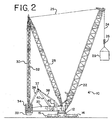
旋回体20は、車体12に旋回可能に接続されており、旋回体は地面係合部材に対して旋回可能である。旋回体は、旋回リングで車体12に取り付けられ、旋回体20が、地面係合部材14、16に対して軸を中心に旋回できるようになっている。旋回体は、旋回体の前側部分に枢動可能に取り付けられているブーム22と、第1端部が旋回体に取り付けられているマスト28と、マストと旋回体の後側部分との間に接続されている背面連結部材30と、支持部材33上にカウンタウエイト34を有している可動式のカウンタウエイトユニットと、を支持している。カウンタウエイトは、図5に示すように、支持部材33上に個々のカウンタウエイトが多層に積み重なった状態になっている。
The turning
マスト28の最上部とブーム22の間にあるブームホイスト綱具装置ブームホイスト綱具装置25は、カウンタウエイトがクレーンによって持ち上げられる吊り荷の平衡を保つのに使用できるように、ブーム角度を制御するのに用いられ、吊り荷を運搬する。ホイストライン24は、ブーム22から伸長し、フック26を支持している。旋回体20は、運転室、ブームホイスト綱具装置25及びホイストライン24用の引上げドラムの様な、自走式リフトクレーンに普通に見られる他の要素も含んでいる。必要に応じて、ブーム22は、メインブームの最上部に枢動可能に取り付けられているラフィングジブ、又は他のブーム構成要素を備えている。背面連結部材30は、マスト28の最上部に隣接して接続されている。背面連結部材30は、図1に示すように圧縮吊り荷と引張吊り荷の両方を支えるように設計されている格子部材を備えている。クレーン10では、引上げ、移動、設置作業の様なクレーンの操作中、マストは旋回体に対して固定した角度で保持される。
Boom hoist rigging
カウンタウエイトユニットは、旋回体20に対して可動である。マストの最上部に隣接して接続されている引張部材32は、吊り下げモードにおいてカウンタウエイトユニットを支持している。カウンタウエイト移動構造は、旋回体とカウンタウエイトユニットの間に接続され、カウンタウエイトユニットが、マスト最上部より前側の第1位置まで動かされ、そこに保持され、そしてマストの最上部より後側の第2位置まで動かされ、そこに保持されるようになっている。少なくとも1つのリニアアクチュエータ装置(本実施形態では油圧シリンダ38)と、第1端部が旋回体に、第2端部が油圧シリンダに枢動可能に接続されている少なくとも1つのアームとが、カウンタウエイトの位置を変更するためにクレーン10のカウンタウエイト移動構造に使用されている。アームと油圧シリンダ38は、旋回体とカウンタウエイトユニットの間に接続されており、油圧シリンダを伸縮させると、旋回体に対してカウンタウエイトユニットの位置が変わるようになっている。
The counterweight unit is movable with respect to the revolving
クレーン10では、前記少なくとも1つのアームは、望ましいことに枢動フレーム40とリアアーム36を有している(クローラ同様に、リアアーム36は、実際は左及び右部材の両方を有しており(図4及び図5)、その一方のみが図1で示されており、油圧シリンダは、協働する2つのシリンダを有している。しかしながら、以下の説明では、簡略化のため1つのシリンダ38と1つのアーム36についてのみ言及する)。枢動フレーム40は、旋回体20と油圧シリンダ38の間に接続され、リアアーム36は、枢動フレーム40とカウンタウエイトユニットの間に接続されている。トラニオン37は、リアアーム36と枢動フレーム40の接続に用いられている。油圧シリンダ38は、支持フレーム42で旋回体20に枢動可能に接続されており、この支持フレームは、シリンダ38、枢動フレーム40、及びリアアーム36の幾何学的配置が、全動作範囲に亘ってカウンタウエイトを動かすことが出来るように、油圧シリンダ38を或る地点まで持ち上げている。この様に、シリンダ38が伸縮すると、リアアーム36がカウンタウエイトユニットを移動させるようになっている。
In the
図1は、最前方位置に在るカウンタウエイトユニットを示しているが、図2は、油圧シリンダが部分的に伸張してカウンタウエイトユニットを中間地点に移動させている、第1吊り荷29がフック26から吊り下げられている時の様な状態を示している。図3と図4は、シリンダ38が最も伸張してカウンタウエイトユニットを最も後方位置に移動させている、大きな吊り荷31がフックから吊り下げられているか、又はブームが前方に枢動し、吊り荷を旋回体から遠くに伸ばしている時の様な状態を示している。この様に、クレーン10を操作する方法では、ホイストラインに吊り荷が掛かっていない時、カウンタウエイトはマストの最上部の真下の地点より前側に位置しており、ホイストラインが吊り荷を支持している時、カウンタウエイトはマストの最上部より後側に位置している(ホイストラインに「吊り荷が掛かっていない」という語句は、何ら荷物を持ち上げていないという通常の意味で用いている。勿論、フック及びフック関連部品はかなりの重量を有し、ホイストラインに吊り荷が掛かっていない時も、ホイストラインに張力を加えている)。
FIG. 1 shows the counterweight unit in the foremost position, but FIG. 2 shows a first suspended
先に述べたように、本発明の好適な実施形態では、可動式のカウンタウエイトは、クレーンの操作中に地面に支持されることは無い。クレーンは、吊り荷を引上げ、移動、及び設置することができ、その際、可動式のカウンタウエイトは、吊り荷の平衡を保つためにクレーン操作中は油圧シリンダの伸縮によって、旋回体の前方部分に向けて及びそこから離れる方向に動かされるが、カウンタウエイトは、車体の地面係合部材によって間接的に支持される以外に、地面に支持されることは無い。また、単一の可動式のカウンタウエイトユニットが、クレーン上の唯一の有効なカウンタウエイトである。車体は別の有効なカウンタウエイトを何ら装備していない。カウンタウエイトユニットをクレーンの旋回中心線に極めて近い位置に動かすことができるという事実は、カウンタウエイトは、この構造では大きな後方向の転倒モーメントを生じないことを意味しており、仮に転倒モーメントが生じる場合、車体は付加的なカウンタウエイトを装備する必要が生じることになる(「別の有効なカウンタウエイトを何ら装備していない」という語句は、クレーンが後方に転倒するのを防ぐためにかなりの量のカウンタウエイトを備えるように具体的に設計されている車体を有する従来型のクレーンと差別化されることを意味している)。 As previously mentioned, in a preferred embodiment of the present invention, the movable counterweight is not supported on the ground during crane operation. The crane can lift, move and install the suspended load, with the movable counterweight being attached to the front part of the swivel body by the expansion and contraction of the hydraulic cylinder during crane operation to keep the suspended load balanced. The counterweight is not supported on the ground other than indirectly supported by the ground engaging member of the vehicle body. Also, a single movable counterweight unit is the only effective counterweight on the crane. The car body is not equipped with any other valid counterweight. The fact that the counterweight unit can be moved to a position very close to the turning centerline of the crane means that the counterweight does not produce a large backward tipping moment in this structure, and a tipping moment is temporarily generated. The car body will need to be equipped with an additional counterweight (the phrase “no other valid counterweight” is a significant amount to prevent the crane from tipping backwards) And a conventional crane having a car body specifically designed to have a counterweight).
図6は、本発明の第2の実施形態であるクレーン110を示している。クレーン10と同様に、クレーン110は、車体112、クローラ114及び116、旋回体120、ブーム122、ブームホイスト綱具装置125、吊り荷ホイストライン124、フック126、マスト128、背面連結部材130、引張部材132、及びカウンタウエイトユニット134を有している。クレーン110とクレーン10の主な相違点は、カウンタウエイトユニットを動かすために使用されるシリンダとアームの構造である。クレーン110では、2つの油圧シリンダ136と138が存在する。シリンダ38と同様に、シリンダ138は、旋回体120に枢動可能に接続されている。またアーム140は、一方の端部が旋回体に、他方の端部がシリンダ138に枢動可能に接続されている。しかしながらこの実施形態では、第2の油圧シリンダ136は、クレーン10におけるリアアーム36の様に、アームとカウンタウエイトユニットの間に接続されている。カウンタウエイトユニットは、両方の油圧シリンダが縮められた時の最前方位置と、後方シリンダ136が伸張された場合の中間位置、及び両方のシリンダが一杯に伸張された場合の(破線で示された)最後方位置との間で動かすことが出来る。
FIG. 6 shows a
図7は、第3の実施形態であるクレーン210を示している。クレーン10及び110と同様に、クレーン210は、車体212、クローラ214、旋回体220、ブーム222、ブームホイスト綱具装置225、吊り荷ホイストライン224、フック226、マスト228、背面連結部材230、引張部材232、及びカウンタウエイトユニット234を有している。このクレーンとクレーン10及び110との相違点は、旋回体上に直接支持されている第2のカウンタウエイトユニット237を有していることである。また、カウンタウエイトユニット234を動かすためのアームと油圧シリンダを有する代わりに、このクレーンは、1つの油圧シリンダ236のみを有している。更に、シリンダ236は、旋回体上に支持されている第2のカウンタウエイトに接続されているため、旋回体には間接的にしか接続されていない。この方式では、第2のカウンタウエイトユニット237が前後に動かされると、カウンタウエイトユニット234も動かされる。油圧シリンダ236は、破線で示すように、旋回体の旋回中心線から更に遠くへカウンタウエイト234を動かすため伸ばすことが出来る。
FIG. 7 shows a
図8は、本発明の第4の実施形態であるクレーン310を示している。クレーン10と同様に、クレーン310は、車体312、クローラ314、旋回体320、ブーム322、ブームホイスト綱具装置325、吊り荷ホイストライン324、フック326、マスト328、背面連結部材330、引張部材332、及びカウンタウエイトユニット334を有している。クレーン310とクレーン10の主な相違点は、カウンタウエイトユニットを動かすのに油圧シリンダ336だけが使用され、枢動アームが採用されていないことである。シリンダ38と同様に、にシリンダ336は、旋回体320に枢動可能に接続されている。しかしながら、この実施形態では、油圧シリンダ336は、この場合は間接的に引張部材332に接続されることによってカウンタウエイトユニットに接続されている。カウンタウエイトユニットは、油圧シリンダ336が一方の方向に一杯に伸ばされた時に(破線で表される)最前方位置まで動かされる。カウンタウエイトは、シリンダ336を縮めることで中間位置へ動かされる。カウンタウエイトは、シリンダ336が再び一杯に伸ばされると、最後方位置に動かされる。
FIG. 8 shows a
図9は、本発明の第5の実施形態であるクレーン410を示している。クレーン10と同様に、クレーン410は、車体412、クローラ414及び416、旋回体420、ブーム422、ブームホイスト綱具装置425、吊り荷ホイストライン424、フック426、マスト428、背面連結部材430、引張部材432、及びカウンタウエイトユニット434を有している。クレーン410とクレーン10の主な相違点は、カウンタウエイトユニットを動かすために用いられるシリンダ及びアームの構造と、カウンタウエイトはシリンダを縮めることによって後方に動かされるという点である。クレーン410では、油圧シリンダ436は、旋回体に枢動可能に接続されているが、そこはアーム438が旋回体に接続されている地点より後方である。アーム438は、一方の端部が旋回体に、他方の端部がシリンダ436に枢動可能に接続されている。第2のアーム440は、クレーン10におけるリアアーム36の様に、アーム438とカウンタウエイトユニット434の間に接続されている。カウンタウエイトユニットは、油圧シリンダ436が一杯に伸ばされた時の最前方位置と、シリンダ436が一杯に縮められた時の(破線で示す)最後方位置の間を動かすことができる。
FIG. 9 shows a
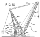
図10から図14は、本発明の第6の実施形態であるクレーン510を示している。クレーン10と同様に、クレーン510は、車体512、クローラ514及び516、旋回体520、ブーム522、ブームホイスト綱具装置525、吊り荷ホイストライン524、フック526、マスト528、背面連結部材530、引張部材532、及びカウンタウエイトユニット534を有している。クレーン510とクレーン10の主な相違点は、背面連結部材の構造と配置、及びアーム538の幾何学的形状である。アーム538は、アーム38のように直線ではなく、枢動フレーム540に接続されている端部に曲線部539を有している。これによって、アーム538は、図4に示すように枢動フレーム40の外側に接続するのではなく、枢動フレーム540の側部部材541と一直線に直接接続できるようになる。曲線部539は、カウンタウエイトが図10に示す実線の位置にある時、アーム538が枢動フレームの側部部材541に干渉するのを防いでいる。
10 to 14 show a
クレーン510では、旋回体は短くされ、そのため旋回体上の背面連結部材530の接続位置が、マストと背面連結部材の接続位置より前側にあり、従って背面連結部材は、旋回体の回転軸に対して或る角度を成している。この角度は、約10°と約20°の間にある。望ましい角度は約16°である。また、背面連結部材530と引張部材532は、マスト528の最上部で接続されてはいないが、マストの上部付近で接続されている。
In the
また、図11を見ればよく分かるように、背面連結部材530は、間隔を空けて配置されている2つの脚部542及び544と、中央の直立部材546とで構成されているA型フレーム構造を有している(図11では、アーム538、シリンダ536、及びカウンタウエイトユニット534は、明瞭にするために示されていない)。直立部材546の格子接続552は、図12に示されている。脚部542と544の格子接続554は、図13に示されている。図14は、枢動フレーム540を構成するために使用されている格子接続556を示している。
As can be seen from FIG. 11, the
脚部542と544は間隔を空けて配置されているので、カウンタウエイト534が外側に向かって旋回する時に、アーム538と枢動フレーム540は、背面連結部材530の脚部542と544の間に嵌まり込むことが出来る。クレーン10では、枢動フレーム40の一番上の格子部材が間隔を空けて十分低い位置に設けられているので、枢動フレーム40が図3に示す位置に来たときでも、枢動フレームの端部は、枢動フレーム40の格子構造が背面連結部材に接触すること無く、背面連結部材30の旋回体20との接続部に位置することができる。カウンタウエイトユニット534は、油圧シリンダ536が一杯に縮んだ時の最前方位置と、シリンダ536が一杯に伸びた時の(破線で示している)最後方位置の間を動かすことが出来る。A型フレーム構造なので、背面連結部材は、枢動フレーム540とアーム538の動きと干渉すること無く、旋回の中心線に近付けて接続することができる。背面連結部材をこの近い位置で接続すると、旋回体をクレーン10に比べ短くすることができる。
Since the
図15から図26は、本発明の第7の実施形態であるクレーン610を示している。クレーン510と同様に、クレーン610は、車体612、クローラー614及び616、旋回体620、ブーム622、ブームホイスト網具装置625、吊り荷ホイストライン624、フック626、マスト628、背面連結部材630、引張部材632、及びカウンタウエイトユニット634を含んでいる。クレーン510と比べてクレーン610の主な相違点は、油圧シリンダの代わりに、リニアアクチュエータ装置としてラックアンドピニオンアセンブリ636を使用していることである。更に、枢動フレーム640は、図11に示すように個々の部材が間隔を空けて溶接された格子構造ではなく、中実の溶接された板構造である。2つの間隔を空けて配置されたアームの代わりに、クレーン610のカウンタウエイト移動構造は、枢動フレーム640と接続されている端部が角度の付いた部分639とされている溶接板構造となっている1つのアーム638を有している。これにより、アーム638を枢動フレーム640と直接一直線に接続することができるようになる。図17は、一体にリンク結合されている枢動フレーム640とアーム638が作業現場の間を運搬する際の折り畳まれている形態を示している。図17は、更に、該枢動フレーム640とアーム638をクレーンの他の部品にピン結合するのに使用される、枢動フレーム640とアーム638のブラケットと穴も示している。例えば、穴652は、リニアアクチュエータ装置636を枢動フレーム640にピン結合するのに使用される。穴654は、フレーム640を旋回体にピン結合するのに使用される。穴656は、アーム638の端部のブラケット659をカウンタウエイトユニット634のフレームにピン結合するのに使用され、穴658は、マストの最上部から吊り下げられている2つのカウンタウエイトストラップ状の引張部材632を、アーム638の端部のブラケット659に、而してカウンタウエイトユニット634に、ピン結合するのに使用される。
15 to 26 show a
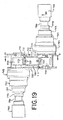
ラックアンドピニオンアセンブリ636の構造は、図18から図23によく分かるように示されており、ラックアンドピニオン作動装置用の駆動システムの代替配置が図24に示されている。カウンタウエイト移動構造は、ハウジング720の内側に取り付けられた溶接板構造で作られているラック710を有するラックアンドピニオンアセンブリを備えている。ハウジング720は、一端に車体接続構造725を含んでおり、車体接続構造725は、ラックアンドピニオンアセンブリ636を旋回体620にピン結合して垂直面内で枢動できるようにするために使用される2つの穴721と、接続構造を旋回体にピン結合して別の方向に枢動できるようにするために使用されるもう1つの穴723とを含んでいる。各ピンは、これらの穴を介して十分な遊びを提供するので、クレーンが旋回をする際に、ラックアンドピニオンアセンブリに曲げモーメントがかかることはない。ラック710は、ピニオンギアを通り過ぎて伸張し、穴711で終端しており、この穴には、ラックを枢動フレーム640に結合するユニバーザルジョイント(図示せず)が設けられている。
The structure of the rack and
ラック710は、互いに対向する第1及び第2側面712、714と、互いに対向する第3及び第4側面716、718とを備えた長方形断面を有している。ラックは、第1側面及び第2側面712及び714上に歯722を含んでいる。歯722は、セグメント化された歯構造体で作られラック710に溶接されている。図19を見ればよく分かるように、歯構造体は、先細上部形状を有しており、外側底部角部に溶接ビード715用の空間となる窪みを含んでいる。歯722の各セグメントは、更に、溶接すると同時に、ボルト717を通して歯セグメントを側面712と714上に保持するのに使用することができる4つの穴を含んでいる。
The
ラックアンドピニオンアセンブリは、ラックの第1側面712上の歯と係合している第1及び第3ピニオンギア731及び733と、ラックの第2側面714上の歯722と係合している第2及び第4ピニオンギア732及び734を有している。各ピニオンギアは、別々の油圧モーターで駆動されており、その内の2つ793と794を図19に示している。第1ピニオンギア731を駆動するモーター(図示せず)は、第3ピニオンギア733を駆動するモーターとは反対側のラック710に隣接するハウジング720の上に取り付けられている。第2ピニオンギア732を駆動するモーター(図示せず)は、第4ピニオンギア734を駆動するモーター794とは反対側のラックに隣接するハウジング720の上に取り付けられている。各油圧モーターは、閉ループ油圧システムで駆動されている。ある好適な実施形態では、クレーン610は、2つのエンジンを有しており、それぞれ8つのポンプを駆動する出力を有している。1つのポンプが2つの油圧モーターを駆動することになる。しかしながら、油圧システム内の弁と、制御システム内の制御装置は、1つのポンプが、ラックアンドピニオンアクチュエータで使用されている4つのモーター全てに油圧出力を供給することができるように設計されているのが望ましい。
The rack and pinion assembly includes first and third pinion gears 731 and 733 engaged with teeth on the
第1及び第4ピニオンギア731及び734を駆動する油圧モーター(モーター794を含む)は、ラック710の第3側面716に隣接するハウジング720の上に取り付けられており、第2及び第3ピニオンギア732及び733を駆動する2つの油圧モーター(モーター793を含む)は、ラック710の第4側面718に隣接するハウジング720の上に取り付けられている。8個のローラー752が、ハウジング720に固定され、ラック710の第1及び第2側面712及び714の周辺部分(歯が取り付けられているところの外側)と回転係合して、構造に安定性を提供している。
Hydraulic motors (including motor 794) that drive the first and fourth pinion gears 731 and 734 are mounted on the
ラックアンドピニオンアセンブリは、更に、各油圧モーターと、その油圧モーターに駆動されているピニオンギアとの間に一連の遊星ギアのセットを備えている。図19と図20を見ればよく分かるように、図示の実施形態では、油圧モーター793とピニオンギア733の間に4組の遊星ギア743、753、763、773が配置されている。また、油圧モーター793の直ぐ右には、ばね式の油圧解除多板ブレーキ783がある。同じモーター、ギア、及びブレーキの配置が、各モーターに設けられている。例えば、遊星ギア744、754、764、774が、ブレーキ784と共にモーター794とピニオンギア734の間に取り付けられている。図24は、ラックアンドピニオンアクチュエータ用駆動システムの異なる実施形態を示している。この実施形態では、モーター駆動894及びブレーキ884部分は、遊星ギアシステム874、864、854、844への直角な入力を有している。このような直角な入力配置にすると、駆動システムへの全長が短くなり、これをサブアセンブリとして梱包出荷し易くなる。
The rack and pinion assembly further includes a series of planetary gear sets between each hydraulic motor and a pinion gear driven by the hydraulic motor. As can be seen from FIGS. 19 and 20, in the illustrated embodiment, four sets of
クレーン610には、カウンタウエイト支持システム810が装備されており、これは、国によってはクレーンの法規に合致している必要がある。本発明のカウンタウエイトユニット634は、旋回体の前側に対してかなり前方に動かすことができるので、支持システム上のカウンタウエイト支持部は、十分に間隔が空いていなければ、旋回と干渉する虞がある。しかしながら、そうすると、支持構造自体が非常に幅広になる。そこで、本願発明者らは、伸縮自在のカウンタウエイト支持システムを含む、カウンタウエイトユニットに取り付けられたカウンタウエイト支持システムを開発した。
The
カウンタウエイト支持システム810は、吊り荷が突然離れたような場合にカウンタウエイトを支持できる、支持脚820の形態をした少なくとも2つの地面係合部材を含んでいる。支持構造810は、地面係合部材820の間の距離を、図25に実線と点線とで示すような、少なくとも第1及び第2位置の間で調節することができるように、地面係合部材820の間に接続されている伸縮自在構造830を備えている。カウンタウエイトユニットは、個々のカウンタウエイトを支持しているカウンタウエイトトレイ840を備えており、伸縮自在構造830は、2つの梁832と、カウンタウエイトトレイ840のチャネル内に嵌合している油圧シリンダ(図示せず)とを含んでいる。伸縮自在構造は、タイヤ支持クレーンで普通に使われているアウトリガーと同様である。カウンタウエイトユニット634は、カウンタウエイト支持構造810を取り外すことができ、クレーンは、それ有り及び無しの両方で機能するように作られている。
The
図26に示すように、カウンタウエイトがその前方位置にあるときには、カウンタウエイト支持部の地面係合部材820は、クレーンの旋回と、十分に引き込まれた第1位置において干渉することになる。しかしながら、この構造を伸ばして、地面係合部材820を、伸張されたその第2位置まで動かせば、クレーンの旋回と干渉することはない。クレーン610のカウンタウエイトユニット634が前方一杯の位置になければ、支持820をその伸張位置まで広げる必要はない。これは、図16に示すように、部分的後方位置では、支持脚820が、旋回中にクローラー614及び616と接触することはないからである。
As shown in FIG. 26, when the counterweight is in its forward position, the
カウンタウエイト634がマスト630の最上部の直下に位置しており、それゆえに、該カウンタウエイトが引張部材632をマスト630の最上部の回りに枢動させることによって描いた弧の地面に最も近い点にあるときに、支持脚820は、なお地面から適切な距離(例えば0.4メートル(15インチ))離れているので、通常のクレーン作動中は、吊り上げ、移動、設置作業中に支持脚が地面と接触することはないように、支持脚820は作られている。その場合、最前方位置(図15に実線で示す)では、支持脚820は1.1メートル(41インチ)の隙間を有しておりカウンタウエイトの一杯に伸張した位置、(図15に点線で示す)では、支持脚820は地面から1.2メートル(47インチ)離れている。
The
本発明の好適な実施形態では、カウンタウエイトユニットは、常にマストと位置決め構造によって支持されている。定格容量未満の吊り荷がフックに加えられる時に、カウンタウエイトを支持するため別の台車が必要になることはない。先行技術の自走式リフトクレーンで使用されているような自由懸垂カウンタウエイトの場合と比べると、カウンタウエイトユニットを地面に置く必要が無い。その結果、クレーン10を操作するのに地面を整える必要性が大幅に削減される。これは、台車が常に設置され、かつ、フックに吊り荷があるか否かにかかわらず、台車が吊り上げ計画の一部でなければならないという、この分野における現在のシステムに勝る非常に大きな利点である。しばしば建設現場での障害物が、クレーンと台車の配置を困難にすることがある。台車を配置するために用いられる最近設計された伸縮システムは、サイズによる影響を軽減するために開発されてきたが、この方式でもなお台車を配備し、考慮せねばならない。台車システムを有する方式の重要な問題部分は、旋回動作中に回転経路を提供することである。台車が極めて長い半径(20から30メートル)で作動している場合、坑木マットが非常に大きな掃引面積に亘って必要になる。本発明の好適な実施形態における自己支持式カウンタウエイトでは、貨車と必要なマットは不要になる。
In a preferred embodiment of the invention, the counterweight unit is always supported by a mast and a positioning structure. When suspended loads below the rated capacity are applied to the hooks, no separate carriage is required to support the counterweight. Compared to the free suspension counterweight used in prior art self-propelled lift cranes, there is no need to place the counterweight unit on the ground. As a result, the need to prepare the ground for operating the
カウンタウエイト移動構造は、クレーンのサイズに応じて、一般に、カウンタウエイトを少なくとも10メートル、望ましくは少なくとも20メートルの距離に亘って動かすことができる。クレーン10の実施形態では、油圧シリンダは、少なくとも5メートルのストロークを有しているのが望ましい。図示の幾何学的配置では、この結果、カウンタウエイトユニットの重心を、旋回体の旋回中心から28メートル(90フィート)の距離まで動かせることになる。一方で、シリンダ38が一杯に縮んだ時、カウンタウエイトユニットの重心は旋回中心から7メートル(23フィート)しか離れていない。この最前方位置は配置機構の幾何学的形状次第で、もっと短くすることもできる。カウンタウエイト移動構造は、カウンタウエイトを旋回軸から7メートル以内の位置に、そして旋回軸から少なくとも28メートル離れた位置まで動かすことができるのが望ましい。クレーン410の実施形態では、カウンタウエイト移動構造は、ほんの5.6メートルのシリンダストロークで少なくとも22メートルの距離に亘ってカウンタウエイトを動かすことができる。この構成では、カウンタウエイトは、旋回軸から約6メートル以内の位置に、そして旋回軸から少なくとも28メートル離れた位置まで動かすことができる。図示される実施形態の様に、カウンタウエイトユニットがマストの最上部から吊り下げられている時、カウンタウエイト移動構造は、引張部材が、旋回軸に対して5°以上、望ましくは10°以上、より望ましくは13°以上の角度を成すように、マストの最上部より前側の位置にカウンタウエイトを動かして保持することができる。カウンタウエイトがマストの最上部より後方の位置にある時、引張部材は、旋回軸に対して少なくとも5°、望ましくは少なくとも10°、より望ましくは15°を越える角度を成している。
Depending on the size of the crane, the counterweight movement structure can generally move the counterweight over a distance of at least 10 meters, preferably at least 20 meters. In the
必要に応じて、シリンダ38又はラックアンドピニオンアセンブリ636の伸張は、吊り上げられる吊り荷及びラフィング操作の平衡を保つために必要な位置へカウンタウエイトユニットを自動的に動かすため、コンピュータによって制御することもできる。その場合、ピンタイプのロードセルが、背面連結部材で吊り荷を検知して、カウンタウエイトを要求される水準の地点へ動かすために使用される。必要に応じて、カウンタウエイトユニットの位置は、シリンダ38又はラックアンドピニオンアセンブリ636等のリニアアクチュエータ装置を一杯に伸縮させることによって可能になる領域内のあらゆる位置の間を無限に変えることが出来る。可変位置システムは、要求される吊り荷モーメントを自己補償する。即ち、一部のカウンタウエイトが装着された場合、カウンタウエイトは要求される吊り荷モーメントを相殺するため自動的に更に後方に配置されることになる。最後方位置に達した時にだけ、クレーンの容量は削減されることになる。
If necessary, the extension of the
本発明の好適な方法では、全てのカウンタウエイトを最後方位置へ動かすと、カウンタウエイトのクレーンの吊り荷モーメントに対する寄与が最大になる。フックに吊り荷が掛けられていない時、カウンタウエイトは可能な限り前方に配置される。この前方配置によって、要求される後方への安定性を維持しながらカウンタウエイトを最大にすることができるようになる。好適な実施形態では、クレーンは、少なくとも250メートルトン、望ましくは少なくとも700メートルトン、より望ましくは少なくとも900メートルトンの合計量のカウンタウエイトと、少なくとも6,250メートルトンメートル(約61.3kN・m)、望ましくは少なくとも17,500メートルトンメートル(約172kN・m)、より望ましくは27,500メートルトンメートル(約270kN・m)の最大定格荷重モーメントと、を有しており、最大定格荷重モーメント対カウンタウエイト合計重量の比は、少なくとも25、望ましくは少なくとも30である。 In the preferred method of the present invention, when all counterweights are moved to the rearmost position, the contribution of the counterweights to the crane load moment is maximized. When the load is not hung on the hook, the counterweight is placed as far forward as possible. This forward arrangement allows the counterweight to be maximized while maintaining the required backward stability. In a preferred embodiment, the crane has a total amount of counterweight of at least 250 metric tons, desirably at least 700 metric tons, more desirably at least 900 metric tons, and at least 6,250 metric tons (about 61.3 kN · m). A maximum rated load moment of at least 17,500 metric tons (about 172 kN · m), more preferably 27,500 metric tons (about 270 kN · m), The ratio of the total weight of the counterweight is at least 25, preferably at least 30.
先に述べたように、先行技術の設計は、一般に3つのカウンタウエイトアセンブリを有している。好適なクレーンの可変位置カウンタウエイトは、唯1つのアセンブリしか有していない。従来設計において1,000メートルトンのカウンタウエイトが必要な場合、単一の可変位置カウンタウエイトを装備するクレーン10は、同等の吊り荷モーメントを発生するために約70%、即ち700メートルトンのカウンタウエイトを必要とすることになる。位置決め機構のコストによって部分的に相殺されるものの、30%のカウンタウエイトの削減は直接的にカウンタウエイトのコスト削減となる。先に述べたように、米国高速道路規制により、300メートルトンのカウンタウエイトは運搬に15台のトラックが必要となる。このため、カウンタウエイトの総量を削減すると、作業現場の間のクレーンの運搬に必要なトラックの数が削減される。位置決め機構は、旋回体の後方部分に一体化され、追加的な運搬トラックは必要ないと想定している。運搬重量を達成するために取り外さなければならない場合、1台のトラックが必要となるであろう。
As previously mentioned, prior art designs typically have three counterweight assemblies. The preferred crane variable position counterweight has only one assembly. When the conventional design requires a counterweight of 1,000 metric tons, a
カウンタウエイトが大幅に(上記の実施例では300メートルトン)削減されるため、最大地面支承反力も同等量削減される。カウンタウエイトは、吊り荷を吊り上げるのに必要な分だけ後方に配置される。クレーンとカウンタウエイトは、可能な限り小型な状態を保ち、追加的荷重モーメントが必要な時だけ伸長される。更なる特徴は、中間位置での削減されたカウンタウエイトで作動させることの出来る性能である。フックに吊り荷が掛けられていない時、削減されたカウンタウエイトは後方安定性要件と平衡する。その場合、可変位置機能は使用しなくてもよく、クレーンは従来型のリフトクレーンとして作動する。このシステムは拡張可能である。非常に大きな容量のクレーンで見られた利点は、容量300メートルトンのクレーン、及び200メートルトンのように小さな容量のクレーンにおいても発揮されるであろう。 Since the counterweight is greatly reduced (300 metric tons in the above embodiment), the maximum ground bearing reaction force is also reduced by the same amount. The counterweight is arranged rearward as much as necessary for lifting the suspended load. The crane and counterweight remain as small as possible and are extended only when additional load moments are required. A further feature is the ability to operate with reduced counterweights at intermediate positions. When the hook is not loaded, the reduced counterweight is balanced with the rear stability requirement. In that case, the variable position function may not be used and the crane operates as a conventional lift crane. This system is scalable. The advantages seen with very large capacity cranes will also be demonstrated in cranes with a capacity of 300 metric tons and cranes with a capacity as small as 200 metric tons.
カウンタウエイト移動構造用リニアアクチュエータ装置として油圧シリンダーの代わりにラックアンドピニオンアセンブリを使用するのには、幾つかの利点がある。最も重要なものの1つは、本発明を設計する目的である大きなカウンタウエイト動かすのに必要な力を作り出せるだけの大きさの油圧シリンダーのコストは、同じ力と張力を作り出せるラックアンドピニオンアセンブリのコストより高いことである。もう1つは、油圧流体の熱膨張係数は鋼の熱膨張係数より大きいという事実である。つまり、シリンダーを使用して油圧流体が高温になったときのシリンダーの伸張長さの変化は、ラックアンドピニオン装置が同じ稼動条件で変化する長さよりも大きくなる。また、好適なラックアンドピニオンシステムでは、機械的なロック機構を容易に組み込むことができる。 There are several advantages to using a rack and pinion assembly instead of a hydraulic cylinder as a linear actuator device for a counterweight moving structure. One of the most important is that the cost of a hydraulic cylinder that is large enough to produce the force needed to move the large counterweight, which is the purpose of designing the present invention, is the cost of a rack and pinion assembly that can produce the same force and tension. Is higher. Another is the fact that the thermal expansion coefficient of the hydraulic fluid is greater than that of steel. That is, the change in the extension length of the cylinder when the hydraulic fluid becomes hot using the cylinder is greater than the length that the rack and pinion device changes under the same operating conditions. Also, a suitable rack and pinion system can easily incorporate a mechanical locking mechanism.
ここに説明した目下好適な実施形態に対する数々の変更及び修正は、当然のことながら、当業者には自明である。例えば、背面連結部材は、クレーンの吊り上げと運転が背面連結部材に圧縮力を発生させることが無い限り、引張吊り荷だけを支持するように設計されたストラップで構成することもできる。リニアアクチュエータ装置、リアアーム、及び枢動フレームは、図面とは異なるように相互接続してもよいし、カウンタウエイトユニットの所望の動きを実現するために、旋回体とカウンタウエイトユニットの間に接続することもできる。また、クレーンの部品は、図示のように必ずしも直接的に接続される必要は無い。例えば引張部材は、背面連結部材がマストに接続されている箇所の付近で背面連結部材に接続することによってマストに接続してもよい。このような変更や修正は、本発明の精神及び領域から逸脱すること無く及び意図した利点を損なうことなく行うことができる。従って,その様な変更及び修正は、特許請求の範囲によって包括されるよう意図している。 Numerous changes and modifications to the presently preferred embodiments described herein will be apparent to those skilled in the art. For example, the back connection member may comprise a strap designed to support only a tensioned load unless the crane lifting and operation generates a compressive force on the back connection member. The linear actuator device, rear arm, and pivot frame may be interconnected differently from the drawing, or connected between the swivel body and the counterweight unit in order to achieve the desired movement of the counterweight unit. You can also. Also, the crane parts need not be directly connected as shown. For example, the tension member may be connected to the mast by connecting to the back connection member near the location where the back connection member is connected to the mast. Such changes and modifications can be made without departing from the spirit and scope of the present invention and without diminishing its intended advantages. Accordingly, such changes and modifications are intended to be covered by the appended claims.
Claims (24)
吊り荷を吊り上げ、移動、設置する作業を実行するステップであって、前記可動式のカウンタウエイトは、前記吊り上げ、移動、設置作業中は前記吊り荷の平衡を保つために前記リニアアクチュエータ装置を伸縮させることによって前記旋回体の前側の部分から前方及びそこから離れる方向に動かされるが、前記カウンタウエイトは、前記車体の前記地面係合部材によって間接的に支持されている以外は、決して地面によって支持されることは無い、吊り荷を吊り上げ、移動、設置する作業を実行するステップを有する、自走式リフトクレーンの操作方法。 In the method of operating a self-propelled lift crane, the lift crane includes a vehicle body having a movable ground engaging member, and a turn rotatably connected to the vehicle body so as to be turnable with respect to the ground engaging member. A boom pivotably attached to a front portion of the swivel body, a boom from which a hoist line extends, and a mast having a first end attached to the swivel body, At least one linear actuator device and a movable counterweight unit;
A step of lifting, moving and installing a suspended load, wherein the movable counterweight expands and contracts the linear actuator device to keep the suspended load balanced during the lifting, moving and installation operations The counterweight is never supported by the ground except that the counterweight is indirectly supported by the ground engaging member of the vehicle body. A method for operating a self-propelled lift crane, comprising a step of performing an operation of lifting, moving, and installing a suspended load that is not performed.
a)可動地面係合部材を有している車体と、
b)前記車体に、前記地面係合部材に対して旋回できるように回転可能に接続されている旋回体と、
c)前記旋回体の前側部分に枢動可能に取り付けられているブームと、
d)第1端部が前記旋回体に取り付けられているマストと、
e)前記マストと前記旋回体の後側部分との間に接続されている背面連結部材と、
f)可動式のカウンタウエイトユニットと、
g)少なくとも1つのリニアアクチュエータ装置と、
h)第1端部が前記旋回体に、第2端部が前記リニアアクチュエータ装置に枢動可能に接続されている少なくとも1つのアームであって、前記アームとリニアアクチュエータ装置は、前記旋回体と前記カウンタウエイトユニットの間に、前記リニアアクチュエータ装置を伸縮させると前記旋回体に対する前記カウンタウエイトの位置が変わるように接続されている、少なくとも1つのアームと、を備えている自走式リフトクレーン。 In self-propelled lift crane,
a) a vehicle body having a movable ground engaging member;
b) a revolving body connected to the vehicle body so as to be rotatable with respect to the ground engaging member;
c) a boom pivotally attached to the front portion of the swivel body;
d) a mast having a first end attached to the swivel body;
e) a back connection member connected between the mast and a rear portion of the swivel body;
f) a movable counterweight unit;
g) at least one linear actuator device;
h) at least one arm having a first end connected to the swing body and a second end pivotally connected to the linear actuator device, the arm and the linear actuator device being connected to the swing body; A self-propelled lift crane that is connected between the counterweight units so that when the linear actuator device is extended or contracted, the position of the counterweight relative to the swivel body is changed.
a)可動地面係合部材を有している車体と、
b)前記地面係合部材に対して旋回できるように、前記車体に、旋回軸を中心に回転可能に接続されている旋回体と、
c)前記旋回体の前側部分に枢動可能に取り付けられているブームと、
d)可動式のカウンタウエイトユニットと、
e)前記カウンタウエイトユニットが前側の位置と後側の位置の両方に動かされてそこに保持されるように、前記旋回体と前記カウンタウエイトユニットの間に接続されているカウンタウエイト移動構造と、を備えており、
f)前記カウンタウエイト移動構造は、ハウジングとラックとを有するラックアンドピニオンアセンブリを備えており、前記ラックは、互いに対向する第1及び第2側面と互いに対向する第3及び第4側面とを備えた長方形断面を有しており、且つ前記第1側面及び前記第2側面上に歯を有しており、少なくとも第1及び第3ピニオンギアは前記ラックの前記第1側面上の前記歯と係合しており、第2及び第4ピニオンギアは前記ラックの前記第2側面上の前記歯と係合しており、また、各ピニオンギアは別々の油圧モーターで駆動されており、前記第1ピニオンギアを駆動する前記モーターは、前記第3ピニオンギアを駆動する前記モーターとは反対側の前記ラックに隣接する前記ハウジングの上に取り付けられており、前記第2ピニオンギアを駆動する前記モーターは、前記第4ピニオンギアを駆動する前記モーターとは反対側の前記ラックに隣接する前記ハウジングの上に取り付けられている、自走式リフトクレーン。 In self-propelled lift crane,
a) a vehicle body having a movable ground engaging member;
b) a revolving body connected to the vehicle body so as to be rotatable about a revolving axis so as to be able to revolve with respect to the ground engaging member;
c) a boom pivotally attached to the front portion of the swivel body;
d) a movable counterweight unit;
e) a counterweight moving structure connected between the swivel body and the counterweight unit so that the counterweight unit is moved to and held at both the front position and the rear position; With
f) The counterweight moving structure includes a rack and pinion assembly having a housing and a rack, and the rack includes first and second side surfaces facing each other and third and fourth side surfaces facing each other. A rectangular cross section and teeth on the first and second side surfaces, at least the first and third pinion gears being engaged with the teeth on the first side surface of the rack. The second and fourth pinion gears are engaged with the teeth on the second side of the rack, and each pinion gear is driven by a separate hydraulic motor, The motor driving the pinion gear is mounted on the housing adjacent to the rack opposite to the motor driving the third pinion gear, and the second pinion The motor, the and the fourth the motor for driving the pinion gear is mounted on said housing adjacent to the rack opposite, mobile lift crane which drives the A.
a)可動地面係合部材を有している車体と、
b)前記地面係合部材に対して旋回できるように、前記車体に回転可能に接続されている旋回体と、
c)前記旋回体の前側部分に枢動可能に取り付けられており、吊り荷を取り扱うための吊り荷ホイストラインを含んでいるブームと、
d)可動式のカウンタウエイトユニットと、
e)前記カウンタウエイトユニットが前側の位置と後側の位置の両方に動かされてそこに保持されるように、前記旋回体と前記カウンタウエイトユニットの間に接続されているカウンタウエイト移動構造と、
f)前記吊り荷が突然離れた場合に前記カウンタウエイトを支持できる少なくとも2つの地面係合部材を含む、前記カウンタウエイトユニットに取り付けられているカウンタウエイト支持構造であって、前記地面係合部材の間の距離が少なくとも第1及び第2位置の間で調整できるように前記地面係合部材の間に接続されている伸縮自在構造を備えているカウンタウエイト支持構造と、を備えている、自走式リフトクレーン。 In self-propelled lift crane,
a) a vehicle body having a movable ground engaging member;
b) a swiveling body rotatably connected to the vehicle body so as to be able to swivel with respect to the ground engaging member;
c) a boom pivotally attached to the front portion of the swivel body and including a suspended load hoist line for handling suspended loads;
d) a movable counterweight unit;
e) a counterweight moving structure connected between the swivel body and the counterweight unit so that the counterweight unit is moved to and held at both the front position and the rear position;
f) a counterweight support structure attached to the counterweight unit, the counterweight support structure including at least two ground engaging members capable of supporting the counterweight when the suspended load suddenly leaves. A counterweight support structure comprising a telescopic structure connected between the ground engaging members so that a distance between the at least first and second positions can be adjusted. Lift crane.
Applications Claiming Priority (4)
| Application Number | Priority Date | Filing Date | Title |
|---|---|---|---|
| US11/733,104 US7546928B2 (en) | 2006-10-27 | 2007-04-09 | Mobile lift crane with variable position counterweight |
| US11/733,104 | 2007-04-09 | ||
| US12/023,902 US7967158B2 (en) | 2006-10-27 | 2008-01-31 | Mobile lift crane with variable position counterweight |
| US12/023,902 | 2008-01-31 |
Publications (3)
| Publication Number | Publication Date |
|---|---|
| JP2009007164A true JP2009007164A (en) | 2009-01-15 |
| JP2009007164A5 JP2009007164A5 (en) | 2009-04-30 |
| JP5276867B2 JP5276867B2 (en) | 2013-08-28 |
Family
ID=39564243
Family Applications (1)
| Application Number | Title | Priority Date | Filing Date |
|---|---|---|---|
| JP2008077842A Active JP5276867B2 (en) | 2007-04-09 | 2008-03-25 | Self-propelled lift crane equipped with variable position counterweight unit and its operating method |
Country Status (4)
| Country | Link |
|---|---|
| EP (4) | EP2589565B1 (en) |
| JP (1) | JP5276867B2 (en) |
| KR (1) | KR20080091706A (en) |
| CN (2) | CN101311102B (en) |
Cited By (6)
| Publication number | Priority date | Publication date | Assignee | Title |
|---|---|---|---|---|
| JP2011037634A (en) * | 2009-08-06 | 2011-02-24 | Manitowoc Crane Companies Llc | Lift crane with movable counterweight |
| JP2011162306A (en) * | 2010-02-09 | 2011-08-25 | Kobelco Cranes Co Ltd | Mobile crane |
| JP2016088752A (en) * | 2014-10-31 | 2016-05-23 | リープヘル−ヴェルク エーインゲン ゲーエムベーハーLiebherr−Werk EhingenGmbH | Mobile crane with ballast receiving device |
| US10179722B2 (en) | 2014-01-27 | 2019-01-15 | Manitowoc Crane Companies, Llc | Lift crane with improved movable counterweight |
| US10183848B2 (en) | 2014-01-27 | 2019-01-22 | Manitowoc Crane Companies, Llc | Height adjustment mechanism for an auxiliary member on a crane |
| US10336589B2 (en) | 2006-10-27 | 2019-07-02 | Manitowoc Crane Companies, Llc | Mobile lift crane with variable position counterweight |
Families Citing this family (13)
| Publication number | Priority date | Publication date | Assignee | Title |
|---|---|---|---|---|
| CN101774514B (en) * | 2010-01-26 | 2012-02-22 | 昆山三一机械有限公司 | Super-starting balance weight stepless luffing mechanism of crawler crane and operating method thereof |
| CN102229415B (en) * | 2011-06-30 | 2013-07-17 | 三一汽车起重机械有限公司 | Crane and movable-type balance weight mechanism thereof |
| CN102556860A (en) * | 2012-03-19 | 2012-07-11 | 昆山三一机械有限公司 | A-frame assembly and crane comprising same |
| DE102012006494B4 (en) | 2012-03-30 | 2014-03-13 | Manitowoc Crane Group France Sas | Mobile crane with decoupling counterweight arrangement |
| CN103964324B (en) * | 2014-04-23 | 2016-08-17 | 中联重科股份有限公司 | Supporting leg counter weight device and include the crane of this supporting leg counter weight device |
| RU2577720C1 (en) * | 2014-09-24 | 2016-03-20 | Олег Станиславович Баринов | Self-propelled jib crane |
| NO2694425T3 (en) * | 2015-01-28 | 2018-04-28 | ||
| DE102016212517A1 (en) * | 2016-07-08 | 2018-01-11 | Terex Global Gmbh | Counterweight adjustment device for a crane, crane and method for adjusting a counterweight on a crane |
| CN106744393B (en) * | 2017-03-03 | 2018-07-17 | 合肥工业大学 | With the hoisting apparatus and control method for adjusting stabilizing mechanism |
| CN109185409A (en) * | 2018-11-16 | 2019-01-11 | 徐州徐工随车起重机有限公司 | A kind of telescopic arm support gear and rack teeth mechanism |
| CN109179221A (en) * | 2018-11-20 | 2019-01-11 | 威海星宜新材料科技有限公司 | A kind of narrow space lifting vehicle |
| CN113582053A (en) * | 2021-07-21 | 2021-11-02 | 浙江三一装备有限公司 | Rotary table structure for realizing counterweight displacement and operation machine |
| CN113526381A (en) * | 2021-07-21 | 2021-10-22 | 浙江三一装备有限公司 | Turntable structure capable of realizing lift of balance weight and operation machine |
Citations (8)
| Publication number | Priority date | Publication date | Assignee | Title |
|---|---|---|---|---|
| JPS5796190U (en) * | 1980-12-04 | 1982-06-12 | ||
| JPS6332893U (en) * | 1986-08-14 | 1988-03-03 | ||
| JPH02182696A (en) * | 1988-11-09 | 1990-07-17 | Manitowoc Co Inc:The | Crane and attachment for increasing hoisting capacity thereof |
| DE29723587U1 (en) * | 1997-07-04 | 1998-11-05 | Mannesmann Ag | Mobile crane, especially large crane |
| JPH11157780A (en) * | 1997-11-21 | 1999-06-15 | Tadano Ltd | Outrigger device of mobile crane |
| JP2002531357A (en) * | 1998-12-04 | 2002-09-24 | アテックス・マンネスマン・アクチエンゲゼルシャフト | Cranes, especially mobile cranes |
| JP2003184086A (en) * | 2001-12-25 | 2003-07-03 | Nippon Sharyo Seizo Kaisha Ltd | Rise and fall device of piling machine |
| JP2005138962A (en) * | 2003-11-07 | 2005-06-02 | Mitsubishi Heavy Ind Ltd | Load handling vehicle |
Family Cites Families (9)
| Publication number | Priority date | Publication date | Assignee | Title |
|---|---|---|---|---|
| GB190594A (en) * | 1921-11-01 | 1922-12-28 | Ernest Wigglesworth Westwood | Improvements in or relating to cranes |
| US1756106A (en) * | 1928-05-16 | 1930-04-29 | Harold E Swenson | Counterbalanced crane |
| DE1281128B (en) * | 1965-12-06 | 1968-10-24 | E H Hans Liebherr Dr Ing | Mobile multi-purpose crane |
| US3930583A (en) * | 1972-07-31 | 1976-01-06 | Creusot-Loire | Balancing system for high capacity cranes |
| DE2451105A1 (en) * | 1974-10-28 | 1976-04-29 | Kocks Gmbh Friedrich | DRIVE FOR A RACK |
| FR2497903B1 (en) * | 1981-01-14 | 1985-09-06 | Brissonneau & Lotz | DOUBLE RACK FOR "PINIONS AND RACK" TYPE LIFTING DEVICE FOR MARINE PLATFORMS |
| JPS62203891A (en) * | 1986-03-04 | 1987-09-08 | Kobe Steel Ltd | Travelling motion control device for connected type working machine |
| DE3838975A1 (en) * | 1988-11-14 | 1990-05-17 | Mannesmann Ag | Mobile crane |
| DE29816385U1 (en) | 1998-09-11 | 1999-04-08 | Liebherr Werk Ehingen | Crane, preferably derrick |
-
2008
- 2008-03-25 JP JP2008077842A patent/JP5276867B2/en active Active
- 2008-04-01 EP EP13153486.9A patent/EP2589565B1/en active Active
- 2008-04-01 EP EP14183968.8A patent/EP2829500B1/en active Active
- 2008-04-01 EP EP16173277.1A patent/EP3106420B1/en active Active
- 2008-04-01 EP EP08251277.3A patent/EP1990306B1/en active Active
- 2008-04-01 KR KR1020080030105A patent/KR20080091706A/en not_active Application Discontinuation
- 2008-04-09 CN CN2008100924076A patent/CN101311102B/en not_active Ceased
- 2008-04-09 CN CN201010624732XA patent/CN102092644A/en active Pending
Patent Citations (8)
| Publication number | Priority date | Publication date | Assignee | Title |
|---|---|---|---|---|
| JPS5796190U (en) * | 1980-12-04 | 1982-06-12 | ||
| JPS6332893U (en) * | 1986-08-14 | 1988-03-03 | ||
| JPH02182696A (en) * | 1988-11-09 | 1990-07-17 | Manitowoc Co Inc:The | Crane and attachment for increasing hoisting capacity thereof |
| DE29723587U1 (en) * | 1997-07-04 | 1998-11-05 | Mannesmann Ag | Mobile crane, especially large crane |
| JPH11157780A (en) * | 1997-11-21 | 1999-06-15 | Tadano Ltd | Outrigger device of mobile crane |
| JP2002531357A (en) * | 1998-12-04 | 2002-09-24 | アテックス・マンネスマン・アクチエンゲゼルシャフト | Cranes, especially mobile cranes |
| JP2003184086A (en) * | 2001-12-25 | 2003-07-03 | Nippon Sharyo Seizo Kaisha Ltd | Rise and fall device of piling machine |
| JP2005138962A (en) * | 2003-11-07 | 2005-06-02 | Mitsubishi Heavy Ind Ltd | Load handling vehicle |
Cited By (13)
| Publication number | Priority date | Publication date | Assignee | Title |
|---|---|---|---|---|
| US11884522B2 (en) | 2006-10-27 | 2024-01-30 | Grove U.S. L.L.C. | Mobile lift crane with variable position counterweight |
| US10336589B2 (en) | 2006-10-27 | 2019-07-02 | Manitowoc Crane Companies, Llc | Mobile lift crane with variable position counterweight |
| US10457530B2 (en) | 2009-08-06 | 2019-10-29 | Manitowoc Cranes, Llc | Lift crane with moveable counterweight |
| US9278834B2 (en) | 2009-08-06 | 2016-03-08 | Manitowoc Crane Group, LLC | Lift crane with moveable counterweight |
| JP2016128358A (en) * | 2009-08-06 | 2016-07-14 | マニタウォック クレイン カンパニーズ, エルエルシーManitowoc Crane Companies, Llc | Lift crane with moveable counterweight |
| JP2018108897A (en) * | 2009-08-06 | 2018-07-12 | マニタウォック クレイン カンパニーズ, エルエルシーManitowoc Crane Companies, Llc | Lift crane including movable counterweight |
| JP2011037634A (en) * | 2009-08-06 | 2011-02-24 | Manitowoc Crane Companies Llc | Lift crane with movable counterweight |
| US11261064B2 (en) | 2009-08-06 | 2022-03-01 | Manitowoc Cranes, Llc | Lift crane with moveable counterweight |
| JP2011162306A (en) * | 2010-02-09 | 2011-08-25 | Kobelco Cranes Co Ltd | Mobile crane |
| US10179722B2 (en) | 2014-01-27 | 2019-01-15 | Manitowoc Crane Companies, Llc | Lift crane with improved movable counterweight |
| US11208303B2 (en) | 2014-01-27 | 2021-12-28 | Manitowoc Crane Companies, Llc | Lift crane with improved movable counterweight |
| US10183848B2 (en) | 2014-01-27 | 2019-01-22 | Manitowoc Crane Companies, Llc | Height adjustment mechanism for an auxiliary member on a crane |
| JP2016088752A (en) * | 2014-10-31 | 2016-05-23 | リープヘル−ヴェルク エーインゲン ゲーエムベーハーLiebherr−Werk EhingenGmbH | Mobile crane with ballast receiving device |
Also Published As
| Publication number | Publication date |
|---|---|
| EP3106420B1 (en) | 2018-06-06 |
| EP1990306A2 (en) | 2008-11-12 |
| EP2589565A1 (en) | 2013-05-08 |
| EP3106420A1 (en) | 2016-12-21 |
| JP5276867B2 (en) | 2013-08-28 |
| EP2829500A3 (en) | 2015-03-18 |
| CN101311102B (en) | 2011-03-09 |
| CN101311102A (en) | 2008-11-26 |
| EP2589565B1 (en) | 2014-09-10 |
| EP2829500A2 (en) | 2015-01-28 |
| EP1990306A3 (en) | 2008-12-03 |
| KR20080091706A (en) | 2008-10-14 |
| EP2829500B1 (en) | 2016-06-08 |
| EP1990306B1 (en) | 2013-11-06 |
| CN102092644A (en) | 2011-06-15 |
Similar Documents
| Publication | Publication Date | Title |
|---|---|---|
| JP5276867B2 (en) | Self-propelled lift crane equipped with variable position counterweight unit and its operating method | |
| US11884522B2 (en) | Mobile lift crane with variable position counterweight | |
| JP5297624B2 (en) | Self-propelled lift crane equipped with variable position counterweight unit and its operating method | |
| JP2009007164A5 (en) | ||
| JP5475960B2 (en) | Mast raising structure and process for high capacity mobile lift crane | |
| US20100072156A1 (en) | Boom Hoist Transportation System and Crane Using Same | |
| RU93078U1 (en) | HYDRAULIC CRANE | |
| RU2467946C2 (en) | Self-propelled crane and method of its operation | |
| RU2429982C1 (en) | Cantilever rotary crane mounted on vehicle platform | |
| JP5617333B2 (en) | Crawler crane | |
| JP2007326712A (en) | Simple crane for truck |
Legal Events
| Date | Code | Title | Description |
|---|---|---|---|
| A621 | Written request for application examination |
Free format text: JAPANESE INTERMEDIATE CODE: A621 Effective date: 20081020 |
|
| A521 | Request for written amendment filed |
Free format text: JAPANESE INTERMEDIATE CODE: A523 Effective date: 20090313 |
|
| A977 | Report on retrieval |
Free format text: JAPANESE INTERMEDIATE CODE: A971007 Effective date: 20111121 |
|
| A131 | Notification of reasons for refusal |
Free format text: JAPANESE INTERMEDIATE CODE: A131 Effective date: 20111124 |
|
| A601 | Written request for extension of time |
Free format text: JAPANESE INTERMEDIATE CODE: A601 Effective date: 20120223 |
|
| A602 | Written permission of extension of time |
Free format text: JAPANESE INTERMEDIATE CODE: A602 Effective date: 20120228 |
|
| A601 | Written request for extension of time |
Free format text: JAPANESE INTERMEDIATE CODE: A601 Effective date: 20120323 |
|
| A602 | Written permission of extension of time |
Free format text: JAPANESE INTERMEDIATE CODE: A602 Effective date: 20120328 |
|
| A601 | Written request for extension of time |
Free format text: JAPANESE INTERMEDIATE CODE: A601 Effective date: 20120423 |
|
| A602 | Written permission of extension of time |
Free format text: JAPANESE INTERMEDIATE CODE: A602 Effective date: 20120426 |
|
| A521 | Request for written amendment filed |
Free format text: JAPANESE INTERMEDIATE CODE: A523 Effective date: 20120524 |
|
| A131 | Notification of reasons for refusal |
Free format text: JAPANESE INTERMEDIATE CODE: A131 Effective date: 20130108 |
|
| A521 | Request for written amendment filed |
Free format text: JAPANESE INTERMEDIATE CODE: A523 Effective date: 20130408 |
|
| A601 | Written request for extension of time |
Free format text: JAPANESE INTERMEDIATE CODE: A601 Effective date: 20130408 |
|
| A602 | Written permission of extension of time |
Free format text: JAPANESE INTERMEDIATE CODE: A602 Effective date: 20130411 |
|
| TRDD | Decision of grant or rejection written | ||
| A01 | Written decision to grant a patent or to grant a registration (utility model) |
Free format text: JAPANESE INTERMEDIATE CODE: A01 Effective date: 20130507 |
|
| A61 | First payment of annual fees (during grant procedure) |
Free format text: JAPANESE INTERMEDIATE CODE: A61 Effective date: 20130520 |
|
| R150 | Certificate of patent or registration of utility model |
Free format text: JAPANESE INTERMEDIATE CODE: R150 Ref document number: 5276867 Country of ref document: JP Free format text: JAPANESE INTERMEDIATE CODE: R150 |
|
| R250 | Receipt of annual fees |
Free format text: JAPANESE INTERMEDIATE CODE: R250 |
|
| R250 | Receipt of annual fees |
Free format text: JAPANESE INTERMEDIATE CODE: R250 |
|
| R250 | Receipt of annual fees |
Free format text: JAPANESE INTERMEDIATE CODE: R250 |
|
| R250 | Receipt of annual fees |
Free format text: JAPANESE INTERMEDIATE CODE: R250 |
|
| R250 | Receipt of annual fees |
Free format text: JAPANESE INTERMEDIATE CODE: R250 |
|
| R250 | Receipt of annual fees |
Free format text: JAPANESE INTERMEDIATE CODE: R250 |
|
| R250 | Receipt of annual fees |
Free format text: JAPANESE INTERMEDIATE CODE: R250 |
|
| R250 | Receipt of annual fees |
Free format text: JAPANESE INTERMEDIATE CODE: R250 |