JP5475960B2 - Mast raising structure and process for high capacity mobile lift crane - Google Patents
Mast raising structure and process for high capacity mobile lift crane Download PDFInfo
- Publication number
- JP5475960B2 JP5475960B2 JP2008105494A JP2008105494A JP5475960B2 JP 5475960 B2 JP5475960 B2 JP 5475960B2 JP 2008105494 A JP2008105494 A JP 2008105494A JP 2008105494 A JP2008105494 A JP 2008105494A JP 5475960 B2 JP5475960 B2 JP 5475960B2
- Authority
- JP
- Japan
- Prior art keywords
- mast
- hydraulic cylinder
- crane
- counterweight
- arm
- Prior art date
- Legal status (The legal status is an assumption and is not a legal conclusion. Google has not performed a legal analysis and makes no representation as to the accuracy of the status listed.)
- Active
Links
- 238000000034 method Methods 0.000 title claims description 16
- 238000009434 installation Methods 0.000 claims description 26
- 238000011900 installation process Methods 0.000 claims description 2
- 230000008602 contraction Effects 0.000 claims 1
- 230000008901 benefit Effects 0.000 description 5
- 230000005484 gravity Effects 0.000 description 3
- 238000012986 modification Methods 0.000 description 3
- 230000004048 modification Effects 0.000 description 3
- 230000002452 interceptive effect Effects 0.000 description 2
- 238000013459 approach Methods 0.000 description 1
- 230000008859 change Effects 0.000 description 1
- 238000010276 construction Methods 0.000 description 1
- 230000003467 diminishing effect Effects 0.000 description 1
- 230000007246 mechanism Effects 0.000 description 1
- 239000013585 weight reducing agent Substances 0.000 description 1
- 238000004804 winding Methods 0.000 description 1
Images


Classifications
-
- B—PERFORMING OPERATIONS; TRANSPORTING
- B66—HOISTING; LIFTING; HAULING
- B66C—CRANES; LOAD-ENGAGING ELEMENTS OR DEVICES FOR CRANES, CAPSTANS, WINCHES, OR TACKLES
- B66C23/00—Cranes comprising essentially a beam, boom, or triangular structure acting as a cantilever and mounted for translatory of swinging movements in vertical or horizontal planes or a combination of such movements, e.g. jib-cranes, derricks, tower cranes
- B66C23/62—Constructional features or details
- B66C23/72—Counterweights or supports for balancing lifting couples
- B66C23/74—Counterweights or supports for balancing lifting couples separate from jib
- B66C23/76—Counterweights or supports for balancing lifting couples separate from jib and movable to take account of variations of load or of variations of length of jib
-
- B—PERFORMING OPERATIONS; TRANSPORTING
- B66—HOISTING; LIFTING; HAULING
- B66C—CRANES; LOAD-ENGAGING ELEMENTS OR DEVICES FOR CRANES, CAPSTANS, WINCHES, OR TACKLES
- B66C23/00—Cranes comprising essentially a beam, boom, or triangular structure acting as a cantilever and mounted for translatory of swinging movements in vertical or horizontal planes or a combination of such movements, e.g. jib-cranes, derricks, tower cranes
- B66C23/18—Cranes comprising essentially a beam, boom, or triangular structure acting as a cantilever and mounted for translatory of swinging movements in vertical or horizontal planes or a combination of such movements, e.g. jib-cranes, derricks, tower cranes specially adapted for use in particular purposes
- B66C23/36—Cranes comprising essentially a beam, boom, or triangular structure acting as a cantilever and mounted for translatory of swinging movements in vertical or horizontal planes or a combination of such movements, e.g. jib-cranes, derricks, tower cranes specially adapted for use in particular purposes mounted on road or rail vehicles; Manually-movable jib-cranes for use in workshops; Floating cranes
- B66C23/46—Mobile jib-cranes with non-slewable jibs
-
- B—PERFORMING OPERATIONS; TRANSPORTING
- B66—HOISTING; LIFTING; HAULING
- B66C—CRANES; LOAD-ENGAGING ELEMENTS OR DEVICES FOR CRANES, CAPSTANS, WINCHES, OR TACKLES
- B66C23/00—Cranes comprising essentially a beam, boom, or triangular structure acting as a cantilever and mounted for translatory of swinging movements in vertical or horizontal planes or a combination of such movements, e.g. jib-cranes, derricks, tower cranes
- B66C23/18—Cranes comprising essentially a beam, boom, or triangular structure acting as a cantilever and mounted for translatory of swinging movements in vertical or horizontal planes or a combination of such movements, e.g. jib-cranes, derricks, tower cranes specially adapted for use in particular purposes
- B66C23/36—Cranes comprising essentially a beam, boom, or triangular structure acting as a cantilever and mounted for translatory of swinging movements in vertical or horizontal planes or a combination of such movements, e.g. jib-cranes, derricks, tower cranes specially adapted for use in particular purposes mounted on road or rail vehicles; Manually-movable jib-cranes for use in workshops; Floating cranes
- B66C23/42—Cranes comprising essentially a beam, boom, or triangular structure acting as a cantilever and mounted for translatory of swinging movements in vertical or horizontal planes or a combination of such movements, e.g. jib-cranes, derricks, tower cranes specially adapted for use in particular purposes mounted on road or rail vehicles; Manually-movable jib-cranes for use in workshops; Floating cranes with jibs of adjustable configuration, e.g. foldable
Description
本出願は、リフトクレーンに、特に、メインブームの後方にカウンタウエイトを支持しているマストを有する高容量移動式リフトクレーン及び該クレーンの組立設置作業時に該クレーンのマストを起こす方法に関する。 The present application relates to a lift crane, in particular, a high-capacity mobile lift crane having a mast supporting a counterweight behind a main boom, and a method for raising the crane during assembly work of the crane.
高容量移動式リフトクレーンは、通常、可動地面係合部材を有する車体と、地面係合部材に対して旋回可能となるように車体に回転可能に接続されている旋回体と、旋回体の前側部分に枢動可能に取り付けられているブームであって、そこからホイストラインが伸長しているブームと、旋回体に取り付けられているマストと、クレーンが吊り荷を持ち上げるときに、クレーンの平衡を保つ役割を果たすカウンタウエイトと、を備えている。マストは、ブームホイスト綱具装置を含め、索具を支持するために使用されているので、吊り荷を持ち上げている力を、車体の後部とカウンタウエイトに伝達する。時には、カウンタウエイトトレーラのような、予備のカウンタウエイト付属部品をクレーンに加えることによって、移動式リフトクレーンの容量を更に強化する場合もある。吊り荷は、クレーンの旋回中心に対して頻繁に内側及び外側に動かされ、その結果、クレーンの引き上げ、移動、及び設置作業中に異なるモーメントが発生するので、予備のカウンタウエイト付属部品を含むカウンタウエイトも、同様にクレーンの旋回中心に対して前方及び後方に動かせれば好都合である。この様にすれば、カウンタウエイトを一定距離に保持しなければならない場合に必要とされる量より少ない量のカウンタウエイトを使用できるようになる。マストは、カウンタウエイトストラップの様な、カウンタウエイトに結合される引っ張り部材を含む索具を支持するように設計しなければならない。このような高容量クレーン用のマストは、通常複数の格子セグメントで構成され、かなりの大きさの圧縮荷重に耐えることができるように設計されている。 A high-capacity mobile lift crane usually has a vehicle body having a movable ground engaging member, a revolving body rotatably connected to the vehicle body so as to be able to turn with respect to the ground engaging member, and a front side of the revolving body A boom pivotally attached to the part from which the hoist line extends, the mast attached to the swivel, and the crane balance when the crane lifts the load. And a counterweight that plays a role of maintaining. Since the mast is used to support the rigging, including the boom hoist rigging device, the mast transmits the lifting force to the rear part of the vehicle body and the counterweight. Sometimes, the capacity of a mobile lift crane can be further enhanced by adding extra counterweight accessories such as a counterweight trailer to the crane. A counter, including spare counterweight attachments, as the suspended load is frequently moved inwards and outwards with respect to the pivot center of the crane, resulting in different moments during crane lifting, moving, and installation operations. Similarly, it is advantageous if the weight can be moved forward and backward with respect to the pivot center of the crane. In this way, it is possible to use a smaller amount of counterweight than is required when the counterweight must be held at a certain distance. The mast must be designed to support a rigging that includes a tension member that is coupled to the counterweight, such as a counterweight strap. Such a high-capacity crane mast is usually composed of a plurality of lattice segments and is designed to withstand a considerable amount of compressive load.
クレーンは、様々な場所で使用されるので、ある仕事現場から次の現場まで移動できるように設計する必要がある。そのために、クレーンは、高速道路の運搬制限内でトラックによって運搬することのできる大きさ、重量の部品に分解できることが、通常要求される。このように、クレーンの設計によって実現することができる如何なる軽量化も、初期コストのみならず、クレーンが使用され続ける間において、現場間のクレーン移動に関するコストの低減に役立つ。更に、クレーンを分解し組立設置する際の容易さと、分解及び組立設置するための補助クレーンの必要性は、クレーンを使用するための全体的なコストに影響を与える。このように、補助クレーンを組立設置するのに必要な工数を含めて、クレーンを組立設置するのに必要な工数が少なくなれば、クレーンの所有者にとって直接的な利点がある。 Since the crane is used in various places, it needs to be designed so that it can move from one work site to the next. To that end, cranes are usually required to be disassembled into parts that are large and heavy enough to be transported by truck within highway transport restrictions. Thus, any weight reduction that can be achieved by crane design helps reduce not only the initial cost, but also the costs associated with moving the crane between sites while the crane continues to be used. Furthermore, the ease of disassembling and assembling the crane and the need for an auxiliary crane to disassemble and assemble will impact the overall cost of using the crane. Thus, if the number of man-hours required for assembling and installing the crane is reduced, including the man-hours required for assembling and installing the auxiliary crane, there is a direct advantage for the crane owner.
殆どの高容量のクレーンは、最初に地上で構成部品から組み立てられるマストを、補助クレーンで持ち上げて旋回体に取り付けて組立設置される。通常、マストは、クレーンの前部を越えて伸長するように配置される。次に、クレーンの後部でガントリーに接続される索具を使って、マストが直立位置へと引き上げられる。マストは、最終的には後方に傾くように配置されることになるので、マストは、垂直位置を越えて引き上げなければならない。勿論、この地点では、マストは倒れ始めることになる。このため、マストが中心部を通り越すときに、倒れるのを防ぐため、前部からマストに張力を加えなければならない。これは、普通は引き戻し補助クレーンによって提供されるか、或いは、反力を提供するためブームホイスト綱具装置がブームに装着され取り付けられる。ブームホイスト綱具装置を使用するときは、クレーンの組立設置作業者は、マスト吊り上げスプール上でロープを引き、同時に、ブームホイスト綱具装置用のロープを繰り出し、マストをその作業位置まで制御可能に移動できるような熟練者でなければならない。 Most high-capacity cranes are assembled and installed by first lifting a mast assembled from components on the ground with an auxiliary crane and attaching it to a swivel. Usually, the mast is arranged to extend beyond the front of the crane. The mast is then raised to an upright position using rigging connected to the gantry at the rear of the crane. Since the mast will eventually be arranged to tilt backwards, the mast must be lifted beyond the vertical position. Of course, at this point, the mast will start to fall. For this reason, tension must be applied to the mast from the front to prevent it from falling over when the mast passes through the center. This is usually provided by a pull back auxiliary crane or a boom hoist rigging device is mounted and attached to the boom to provide a reaction force. When using the boom hoist rigging device, the crane assembly and installation operator can pull the rope on the mast lifting spool, and at the same time, pull out the rope for the boom hoist rigging device and control the mast to its working position. Must be skilled enough to be able to move.
高容量クレーンの中には、可動機械式マストに加えて、予備のカウンタウエイトユニットが内側及び外側に動かされる際に動かすことのできるデリックマストを使用している、Liebherr LR11350の様なより一層複雑化しているものもある。このデリックマストは、上記メインマストがクレーンに加えられるのと同じやり方で組み立てられ、デリックマストは、最初の前部上の位置から最上部中心上まで引っ張る必要がある。 Some high capacity cranes use a derrick mast that can be moved as the spare counterweight unit is moved in and out in addition to the movable mechanical mast, such as the Liebherr LR11350. Some have become. The derrick mast is assembled in the same way that the main mast is added to the crane, and the derrick mast needs to be pulled from a position on the first front to the top center.
吊上力強化マストを装着し、前部上の位置から起すには、クレーンの組立設置時に高度に熟達したクレーン操作者が必要であるという事実に加えて、マストを起こすのに必要となる構造も重要である。クレーンは、マストのヒンジピン回りのモーメントアームを提供するため、ガントリー又は可動マスト何れかの構造を必要としている。更に、動力付きドラム、ロープ、付帯するプーリー、多くのロープ操作及びマスト起伏機器も必要である。先に述べたように、マストが、中心上の位置に近づいて、次いで作業位置まで制御可能に動かされる際に、マストを後方に保持する手段も必要である。 In addition to the fact that a highly skilled crane operator is required when assembling and installing the crane, the structure required to raise the mast is necessary to mount the lifting force-enhanced mast and get it up from the front position. It is also important. Cranes require either a gantry or movable mast construction to provide a moment arm around the mast hinge pin. In addition, there is a need for powered drums, ropes, attached pulleys, many rope operations and mast hoisting equipment. As previously mentioned, there is also a need for means to hold the mast rearward as the mast approaches a position on the center and then is controllably moved to the working position.
Lampsonへの米国特許第4,349,115号は、メインクレーンの車体とは別体の可動式カウンタウエイトユニットを有するクレーンを開示している。マストは、他の高容量移動式クレーンと同様に、このクレーンにも使用されている。Lampson特許は、マストが、最初に旋回体に取り付けられ、クレーンの後部上を後方に伸長する、組立設置作業を開示している。マストは、その外側端部がカウンタウエイト支柱に取り付けられ、このカウンタウエイト支柱は、可動式カウンタウエイトユニットに取り付けられる。それらは、ほぼ地面の近くで組み立てられる。補助クレーンを使って、マストとカウンタウエイト支柱の接続部をその作業高さに近い高さまで持ち上げるが、その時、カウンタウエイトユニットは、スプレッダーリンクを旋回体と可動式カウンタウエイトユニットの間に接続できるほど、旋回体に近接するまで持って行くことができる。この組立設置作業は、ガントリー、動力付きドラム、プーリー、及びロープ操作を必要としないが、それでもなお、マストだけでなくカウンタウエイト支柱も同様に持ち上げ、更に、それらを、ブームホイスト綱具装置とブーム重量がカウンタウエイトとして働いて、マストをその最終的な作業位置まで引っ張ることのできる高さまで持ち上げることができるだけの容量を有する補助クレーンを必要としている。補助クレーンは、これを達成するために極めて長いブームを有していなければいけない。 U.S. Pat. No. 4,349,115 to Lampson discloses a crane having a movable counterweight unit that is separate from the main crane body. Masts are used in this crane as well as other high-capacity mobile cranes. The Lampson patent discloses an assembly and installation operation in which a mast is first attached to a pivoting body and extends rearward over the rear of the crane. The outer end of the mast is attached to a counterweight post, and this counterweight post is attached to a movable counterweight unit. They are assembled near the ground. Using an auxiliary crane, lift the connection between the mast and the counterweight column to a height close to the working height. At that time, the counterweight unit can connect the spreader link between the swivel body and the movable counterweight unit. Can be taken until close to the swivel. This assembly and installation operation does not require gantry, powered drum, pulley, and rope operations, but nevertheless lifts not only the mast but also the counterweight struts, and further lifts them into the boom hoist rigging device and the boom. There is a need for an auxiliary crane with a capacity that allows the weight to act as a counterweight and lift the mast to a height that can be pulled to its final working position. The auxiliary crane must have a very long boom to achieve this.
このように、高容量移動式リフトクレーンにおける、特に、マストを起こすために使用される構造及び手順における、更なる改善が必要とされている。
マストを起こすために旋回体上に油圧シリンダを使用している移動式リフトクレーンとその組立設置方法が発明された。第1の態様では、本発明は、可動地面係合部材を有する車体と、地面係合部材に対して旋回可能となるように車体に回転可能に接続されている旋回体と、旋回体の前側部分に枢動可能に取り付けられているブームと、第1端部が旋回体に取り付けられており、更に第2端部を有するマストと、第1端部が旋回体に枢動可能に接続されている少なくとも1つの油圧シリンダであって、マストの第2端部を、マストがほぼ水平状態にある位置から、マストがクレーンの引き上げ、移動、及び設置作業中に使用される位置まで起こすことができるように配置及び構成されているシリンダと、を備えている移動式リフトクレーンである。 A mobile lift crane that uses a hydraulic cylinder on a swivel to raise the mast and its assembly and installation method were invented. In a first aspect, the present invention provides a vehicle body having a movable ground engagement member, a swing body that is rotatably connected to the vehicle body so as to be turnable with respect to the ground engagement member, and a front side of the swing body A boom pivotally attached to the part, a first end attached to the swivel body, a mast having a second end, and a first end pivotally connected to the swivel body At least one hydraulic cylinder that raises the second end of the mast from a position where the mast is substantially horizontal to a position where the mast is used during crane lifting, moving, and installation operations. A mobile lift crane comprising a cylinder arranged and configured to be capable.
第2の態様では、本発明は、移動式リフトクレーンを組立設置する方法であり、リフトクレーンは、組立設置時に、可動地面係合部材を有する車体と、地面係合部材に対して旋回可能となるように車体に回転可能に接続されている旋回体と、旋回体の前側部分に枢動可能に取り付けられているブームであって、そこからホイストラインが伸長しているブームと、第1端部が旋回体に取り付けられているマストであって、第1端部と反対側に第2端部を有しているマストと、を備えており、本方法は、マストを旋回体に接続し、マストが旋回体上を後方に伸長するようにマストを配置する段階と、旋回体に接続されている油圧シリンダを使用して、旋回体との接続部回りにマストを枢動させ、それによって、マストの第2端部を起こす段階と、を含んでいる。 In a second aspect, the present invention is a method of assembling and installing a mobile lift crane, and the lift crane is capable of turning with respect to a vehicle body having a movable ground engaging member and a ground engaging member during assembly and installation. A revolving body that is rotatably connected to the vehicle body, a boom that is pivotally attached to a front portion of the revolving body, from which a hoist line extends, and a first end A mast attached to the swivel body, the mast having a second end opposite to the first end, the method connecting the mast to the swivel body , Positioning the mast so that the mast extends backward on the swivel and using a hydraulic cylinder connected to the swivel to pivot the mast around the connection with the swivel, thereby Raising the second end of the mast; Which comprise.
本発明の第3の態様は、移動式リフトクレーンを組立設置する方法であり、本方法は、可動地面係合部材を有する車体と、地面係合部材に対して旋回可能となるように車体に回転可能に接続されている旋回体と、少なくとも1つの油圧シリンダと、を提供する段階と、マストの第1端部を旋回体に枢動可能に固定する段階と、背面連結部材をマストの第1端部から離れた位置で、マストに枢動可能に固定する段階と、油圧シリンダを使用してマストを回転させ、マストと背面連結部材を持ち上げる段階と、背面連結部材を旋回体に接続し、マストを直立位置に支持する段階と、を含んでいる。 According to a third aspect of the present invention, there is provided a method for assembling and installing a mobile lift crane. The method includes a vehicle body having a movable ground engaging member, and a vehicle body that can be turned with respect to the ground engaging member. Providing a swivel that is rotatably connected and at least one hydraulic cylinder; pivotally securing a first end of the mast to the swivel; and connecting the back connecting member to the first of the mast. A stage that is pivotally fixed to the mast at a position away from one end, a stage that rotates the mast using a hydraulic cylinder and lifts the mast and the back connection member, and the back connection member is connected to the swivel body. Supporting the mast in an upright position.
本発明の好適な実施形態では、マストを起すためのモーメントアームを提供するのに別体のガントリーを必要としない上に、マストがクレーンの前方から引き上げられるときに、動力付きドラム、プーリー、ロープ滑車、及び他の機器を使用する必要がないようになっている。更に、引き止め用補助クレーンを必要とせず、カウンタウエイトとしてブームを使用しながらマスト起しロープを巻き取り、同時にブームホイスト綱具装置を繰り出す複雑な操作を行う必要もない。更に、補助クレーンは、マストがカウンタウエイト支柱に取り付けられている状態でマストを高い角度まで起す必要がない。更に、好適な実施形態では、マストを起すために使用される油圧シリンダは、後で、大きなカウンタウエイトを旋回体に近付く及び離れる方向に動かしてカウンタウエイトモーメントを変化させるクレーン操作の間にも使用される。カウンタウエイトの移動構造及びその利点の詳細は、2007年4月9日出願の米国特許出願第11/733,104号に説明されており、同出願を参考文献としてここに援用する。 In a preferred embodiment of the present invention, a separate gantry is not required to provide a moment arm for raising the mast, and a powered drum, pulley, rope when the mast is pulled up from the front of the crane. There is no need to use pulleys and other equipment. Further, there is no need for a holding auxiliary crane, and there is no need to perform a complicated operation of raising the mast and winding the rope while simultaneously using the boom as a counterweight, and at the same time extending the boom hoist rope device. Furthermore, the auxiliary crane does not need to raise the mast to a high angle while the mast is attached to the counterweight post. Further, in a preferred embodiment, the hydraulic cylinder used to raise the mast is later used during crane operations where the large counterweight is moved toward and away from the swivel to change the counterweight moment. Is done. Details of the counterweight movement structure and its advantages are described in US patent application Ser. No. 11 / 733,104 filed Apr. 9, 2007, which is hereby incorporated by reference.
本発明の上記及びこの他の利点、並びに本発明自体については、添付図面を参照することでより理解し易くなるであろう。 The above and other advantages of the present invention, as well as the present invention itself, will be more readily understood with reference to the accompanying drawings.
本発明について、これより以下に説明する。以下の文章では、本発明の異なる態様をより詳細に定義する。ここに定義する各態様は、そうではないと明確に示されていない限り、どの様な他の態様とでも組み合わせることができる。具体的には、望ましい又は好都合であると示されている全ての特徴は、望ましい又は好都合であると示されている他のどの様な特徴とでも組み合わせることができる。 The present invention will now be described below. In the following text, different aspects of the invention are defined in more detail. Each aspect defined herein can be combined with any other aspect, unless explicitly indicated otherwise. In particular, all features indicated as desirable or advantageous can be combined with any other feature indicated as desirable or advantageous.
ここで使用する幾つかの用語は、以下定義する意味を有している。 Some terms used herein have the meanings defined below.
旋回体の前側部分は、吊り荷を吊り上げた時の旋回体の旋回軸と吊り荷の位置の間にある旋回体の部分と定義される。旋回体の後側部分は、旋回軸に関し、旋回体の前側部分と反対側にある全てのものを含んでいる。旋回体の他の部分又はマストの様なそこに接続されている物に言及する用語「前側」及び「後側」(又は「後方」の様なその派生語)は、地面係合部材に対する旋回体の実際の位置に関わらず同じ関係で使用される。 The front side portion of the revolving structure is defined as a part of the revolving structure between the revolving axis of the revolving structure and the position of the suspended load when the suspended load is lifted. The rear part of the swivel body includes everything that is on the opposite side of the swivel body with respect to the swivel axis. The terms “front side” and “rear side” (or derivatives thereof, such as “rear”), which refer to other parts of the swivel body or things connected thereto such as the mast, Used in the same relationship regardless of the actual position of the body.
カウンタウエイトユニットの位置は、全てのカウンタウエイト要素と、カウンタウエイトを取り付けるか又は連動して動く保持台とを組み合わせた重心として定義される。常に同時に動くように一体に繋がれているクレーン上の全てのカウンタウエイトは、重心を定めるため単一のカウンタウエイトとして扱われる。 The position of the counterweight unit is defined as the center of gravity combining all counterweight elements and a holding base that is attached to or moves in conjunction with the counterweight. All counterweights on the crane that are connected together so that they always move simultaneously are treated as a single counterweight to determine the center of gravity.
マストの最上部は、マストに支持されている全ての線又は引張部材が吊り下げられているマスト上の最後部として定義される。マストに線又は引張部材が支持されていない場合、マストの最上部は、背面連結部材が取り付けられている位置である。 The top of the mast is defined as the last part on the mast where all the lines or tension members supported by the mast are suspended. When no line or tension member is supported on the mast, the uppermost part of the mast is the position where the back connection member is attached.
可動地面係合部材は、タイヤ又はクローラーの様に、クレーンが地面上方を移動する間に地面と係合した状態に留まる様に設計されている部材と定義されるが、地面に対して静止している、又は環状支持クレーンにおける環のように、動いている時に地面との接触から持ち上げられるように設計されている地面係合部材を含んでいない。 A movable ground engaging member is defined as a member that is designed to remain engaged with the ground as the crane moves over the ground, such as a tire or crawler, but is stationary with respect to the ground. It does not include a ground engaging member that is designed to be lifted from contact with the ground when moving, such as a ring in an annular support crane.
クレーンを作動させる際に用いる用語「動く」は、地面に対するクレーンの動きを含んでいる。これは、クレーンが地面係合部材上で地面上方を或る距離だけ旋回する移動動作、旋回体が地面に対して旋回する旋回動作、又は移動及び旋回の組合せ動作、の何れでもよい。 The term “move” used in operating a crane includes the movement of the crane relative to the ground. This may be any of a moving operation in which the crane turns on the ground engaging member over the ground by a certain distance, a turning operation in which the turning body turns with respect to the ground, or a combined movement and turning operation.
図1から図10、特に図1と図2に示す第1の実施形態では、移動式リフトクレーン10は、車体12として示されてもいる下方構造体と、クローラー14と16の形態をとる可動地面係合部材とを含んでいる。(当然2つの前クローラー14と2つの後クローラー16が存在し、図1の側面図ではそれらの各々1つのみを示している。他の後方クローラーは、図2の後面図に表されている。)(図2は、明瞭にするために簡略化されており、ブーム、マスト、及びカウンタウエイトユニットは図示していない。)クレーン10では、地面係合部材は、各側に1つのクローラーを有する1組のクローラーでもよい。無論、図示したもの以外に追加のクローラー、又はタイヤの様な他の地面係合部材を使用してもよい。
In the first embodiment shown in FIGS. 1 to 10, particularly in FIGS. 1 and 2, the
旋回体20は、車体12に旋回可能に接続されており、旋回体は地面係合部材に対して旋回可能である。旋回体は、ローラー軌道上を走るローラーで車体12に取り付けられ、旋回体20が、車体、従って地面係合部材14、16に対して軸を中心に旋回できるようになっている。旋回体は、通常、溶接部、及びブーム吊り上げや吊り荷ドラム等の、溶接部に取り付けられている追加部品を含んでいる。溶接部と共に回転する全てのそれらの付属物は、旋回体とみなされる。旋回体は、旋回体の前側部分に枢動可能に取り付けられているブーム22と、第1端部が旋回体に取り付けられているマスト28と、マストと旋回体の後側部分の間に接続されている背面連結部材30と、支持部材又は保持台上にカウンタウエイトを有している可動式のカウンタウエイトユニット34と、を支持している。カウンタウエイトは、支持部材33上に個々のカウンタウエイト部材が多層に積み重なった状態になっている。
The turning
マスト28の最上部とブーム22の間にあるブームホイスト綱具装置25は、カウンタウエイトがクレーンによって持ち上げられる吊り荷の平衡を保つのに使用できるように、ブーム角度を制御するのに用いられ、吊り荷を運搬する。ホイストライン24は、ブーム22から伸長し、フック26を支持している。旋回体20は、運転室、索具25とホイストライン24用の引上げドラムの様な、移動式リフトクレーンに普通に見られる他の要素も含んでいる。必要に応じて、ブーム22は、メインブームの最上部に枢動可能に取り付けられている引込みジブ、又は他のブーム形状を備えている。背面連結部材30は、マスト28の最上部に隣接する位置に接続されている。背面連結部材30は、図1に示すように圧縮荷重と引張荷重の両方を支えるように設計されている格子部材を備えている。クレーン10では、引上げ、移動、設置作業の様なクレーンの作動中、マストは旋回体に対して固定した角度で保持される。
A boom hoist rigging
カウンタウエイトユニットは、旋回体20の台に対して動かすことができる。マストの最上部に隣接する位置に接続されている、カウンタウエイトストラップ32の様な引張部材は、吊り下げモードにおいてカウンタウエイトユニットを支持している。カウンタウエイトの移動構造は、旋回体とカウンタウエイトユニットの間に接続され、カウンタウエイトユニットが、マスト最上部より前側の第1位置まで動かされ、そこに保持され、そしてマストの最上部より後側の第2位置まで動かされ、そこに保持されるようになっている。少なくとも1つの油圧シリンダ36と、第1端部が旋回体に第2端部が油圧シリンダに枢動可能に接続されている少なくとも1つのアームとが、カウンタウエイトの位置を変更するためにクレーン10のカウンタウエイト移動構造に使用されている。アームと油圧シリンダは、旋回体とカウンタウエイトユニットの間に接続されており、油圧シリンダを伸縮させると、旋回体に対してカウンタウエイトユニットの位置が変わるようになっている。図1の破線は、伸長位置にあるカウンタウエイトを示している。
The counterweight unit can be moved with respect to the base of the revolving
クレーン10では、前記少なくとも1つのアームは、望ましいことに枢動フレーム40とリアアーム38を備えている。(クローラー同様に、リアアーム38は、実際は左及び右部材の両方を有しており、その一方のみが図1で示されている。油圧シリンダは、協働して作動する2つのシリンダを備えている場合もあり、或いは枢動フレームの上端中心部に取り付けられている単一のシリンダの場合もある。しかしながら、以下の説明はで、簡略化のため1つのシリンダ36と1つのアーム38についてのみ言及する。更に、図2は、明瞭さのためアーム38とシリンダ26を示していない。)枢動フレーム40は、旋回体20と油圧シリンダ36の間に接続され、リアアーム38は、枢動フレーム40とカウンタウエイトユニット34の間に接続されている。
In the
油圧シリンダ36は、支持フレーム47で旋回体20に枢動可能に接続されており、この支持フレームは、シリンダ36、枢動フレーム40、及びリアアーム38の形状により、カウンタウエイトの全動作範囲に亘ってカウンタウエイトを動かすことが出来るように、油圧シリンダ36を或る地点まで持ち上げている。この様に、シリンダ36が伸縮する際、リアアーム38がカウンタウエイトユニットを移動させるようになっている。
The
アーム38は、直線ではなく、むしろ、枢動フレーム40に接続されている端部において曲線部39を有している。これによって、アーム38は、枢動フレーム40の側部部材41(図2)と一直線に直接接続できるようになる。曲線部39は、カウンタウエイトが図1に示す実線の位置にある時、アーム38が枢動フレームの側部部材41に干渉するのを防いでいる。
The
クレーン10では、旋回体は短く、そのため旋回体上の背面連結部材30の接続位置が、マスト及び背面連結部材の接続位置より前側にあり、従って背面連結部材は、旋回体の回転軸に対して或る角度を成している。この角度は、約10°と約20°の間にある。望ましい角度は約16°である。また、背面連結部材30と引張部材32は、マスト28の最上部で接続されてはいないが、マストの最上部付近で接続されている。
In the
また、図2を見ればよく分かるように、背面連結部材30は、間隔を空けて配置されている2つの脚部42及び44と、中央直立部材46とで構成されているA型フレーム形状を有している。脚部42と44は間隔を空けて配置されているので、カウンタウエイトユニット34が外側に向かって旋回する時に、アーム38と枢動フレーム40は、背面連結部材30の脚部42と44の間に嵌まり込むことが出来る。カウンタウエイトユニット34は、油圧シリンダ36が一杯に縮んだ時の最前方位置と、シリンダ36が一杯に伸びた時の(破線で示している)最後方位置の間を移動可能である。A型フレーム形状なので、背面連結部材は、枢動フレーム40とアーム38の動きに干渉すること無く、クレーン10の旋回の中心線に近付けて接続することができる。背面連結部材をこの近い位置で接続すると、旋回体を他のクレーン設計に比べ短くすることができる。本発明を適用することもできる可動式のカウンタウエイトを備えている高容量移動式リフトクレーンの他の実施形態は、先に言及した米国特許出願第11/733,104号に示されている。
As can be seen from FIG. 2, the
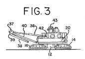
クレーンの組立設置作業及びマスト起し構造の好適な実施形態について、これから説明してゆく。図3は、組立設置の第1段階で地面係合クローラー14と16及び旋回体20が既に取り付けられている車体12を示している。枢動フレーム40、油圧シリンダ36及びリアアーム38を含むカウンタウエイト移動フレームアセンブリも、取り付けられている。これは基本ユニットを構成しており、組み立てられ、マストを受け入れる準備が整っている。ブームホイスト綱具装置25の一部を形成するイコライザアセンブリ43は、旋回体上に配置されており、図3では運搬位置にある状態が示されている。
A preferred embodiment of the crane installation and mast raising structure will now be described. FIG. 3 shows the
図4は、次の組立設置段階にある基本アセンブリを示している。この段階では、イコライザアセンブリ43は、旋回体から引き降ろされ、地面に置かれている。地上で構成部品から組み立てられたマスト28は、補助クレーンで所定の位置まで持ち上げられ、マストのヒンジを形成するピンは、油圧で挿入され、マストを旋回体20に枢動可能に固定している。マスト28は、旋回体の後部上を後方にほぼ水平状態に伸びている。シリンダ36、枢動フレーム40およびリアアーム38が全て接続されているカウンタウエイト移動構造の上に設置されているマスト起しローラー37は、マスト係合部材としての役目を果たし、マストの下面に接している。(カウンタウエイト移動構造の他の部品と同様に、2つのローラー37があるが、図1の側面図では1つのみを示している。)
FIG. 4 shows the basic assembly in the next assembly and installation stage. At this stage, the
組立設置工程の段階3を図5に示している。イコライザアセンブリ43は、ここで分けられ、マスト最上部とマスト支承部に取り付けられる。背面連結部材30は、先ず地上で構成部品から組み立てられ、補助クレーンによって所定の位置まで持ち上げられ、マストの最上部付近にピンで結合される。カウンタウエイトストラップ32も、マスト最上部に接続され、背面連結部材30が所定の位置に持ち上げられる際に、その上に載る。ローラー37、枢動フレーム40及びシリンダ36は、マスト及び背面連結部材30の重量の一部を支持し続ける。
Stage 3 of the assembly and installation process is shown in FIG. The
図6は、組立設置の次の段階を示している。油圧シリンダ36は縮められ、枢動フレーム40を旋回体20の前部に向けて引き寄せる。その際、マスト起しローラー37は、上方向に押し上げられ、マストの下面に沿って転がり、図6に示す位置までマスト28を起こす。背面連結部材には、地面係合ローラーが取り付けられ、マストが起こされる際に背面連結部材が動き易いようにしている。これで、背面連結部材30とカウンタウエイトストラップ32が、マスト28から吊り下げられる。カウンタウエイトユニット34は、補助クレーンで配置される。カウンタウエイト引張部材32は、カウンタウエイト支持部材上のA型フレーム又は保持台が地面に置かれている間は保持台の上に油圧でピン結合される。
FIG. 6 shows the next stage of assembly and installation. The
図7に示す組立設置の次の段階では、シリンダ36は、更に縮められ、ローラー37にマスト28を作業位置まで起こし、更に、カウンタウエイトユニット34を地面から持ち上げる。索具ウィンチ線が背面連結部材に取り付けられ、背面連結部材30の底部は、旋回体20に向けて引き寄せられる。次いで、背面連結部材は、旋回体の後部に対して後部ハウスローラーキャリアビームにおいて油圧でピン結合される。この図から、シリンダは、マストの第2端部を、マストがほぼ水平な位置(図4)から、クレーンの引き上げ、移動、及び設置作業(図7)の間にマストが使用される位置へ起こすことができる様に配置され、構成されていることが分かる。
In the next stage of the assembly and installation shown in FIG. 7, the
背面連結部材30が所定の位置にある状態で、マスト28は、これで背面連結部材によって支持されることになり、ローラー37は必要なくなる。図8は、組立設置の次の段階を示しており、シリンダ36はここで伸ばされ、枢動フレーム40を後方に旋回させる。次に、補助クレーンは、リアアーム38を、カウンタウエイトユニット34上のA型フレームに油圧でピン結合できる場所に引き寄せる。その後、シリンダ36、枢動フレーム40、及びリアアーム38は、カウンタウエイト移動構造として機能し、カウンタウエイトユニット34を旋回体20に向けて又は離れる方向に動かすことが可能となる。図9では、シリンダは、カウンタウエイトユニットが最前方位置に引き寄せられるまで縮められている。
With the
図10は、その1つの最終組立設置段階にあるクレーン10を示している。ブーム22は、地上で組み立てられる。ブーム支承部とブームの第1区画は、補助クレーンによって持ち上げられ、旋回体20に取り付けられる。イコライザアセンブリ43のブーム端部はブーム22の最上部に取り付けられる。カウンタウエイトの追加部片が、カウンタウエイトユニットに加えられる。補助クレーンを使用して、ブームの第2区画を、ブームの全ての区画が接続できる位置まで持ち上げなければならない。その後、ブームホイスト綱具装置25を使って、ブームを図1に示す作業位置まで起す。
FIG. 10 shows the
本発明の好適な実施形態では、Liebherr LR11350の様な他の型式のクレーンで使用されているような何れかのガントリー及びマスト起し索具も必要とせずに、マストを起すことができる。熟練した操作者が、マスト起しロープを引きながらブームホイスト綱具装置を繰り出して、マストを最上部中央位置まで起こす必要はない。更に、上記実施形態では補助クレーンを使用しているが、補助クレーンは、Lampsonの特許で開示されているクレーンのように、カウンタウエイト支柱がマストに取り付けられている状態で、マストの最遠端を作業高付近まで持ち上げる必要はない。このように、非常に短いブームを有する補助クレーンを使用することが可能となる。 In a preferred embodiment of the present invention, the mast can be raised without the need for any gantry and mast rigging as used in other types of cranes such as the Liebherr LR11350. It is not necessary for the skilled operator to raise the mast to the uppermost center position by unwinding the boom hoist rope device while pulling the mast and pulling the rope. Furthermore, although an auxiliary crane is used in the above embodiment, the auxiliary crane is the farthest end of the mast with the counterweight strut attached to the mast, as in the crane disclosed in the Lampson patent. There is no need to lift the to near the working height. In this way, it is possible to use an auxiliary crane having a very short boom.
マストを起すために使用する構造は、2つの機能を有しており、通常のクレーン作業中にはカウンタウエイトユニットを内側及び外側に動かす。このカウンタウエイト移動機構は、それ自体幾つかの利点を有しており、好適な実施形態では、同じ油圧シリンダを2つの別々の機能に使用することができるという事実により、この構造を更に経済的なものにしている。 The structure used to raise the mast has two functions and moves the counterweight unit inward and outward during normal crane operations. This counterweight movement mechanism itself has several advantages, and in the preferred embodiment this structure is more economical due to the fact that the same hydraulic cylinder can be used for two separate functions. It ’s a good thing.
カウンタウエイト移動構造は、クレーンの大きさに応じて、通常は、カウンタウエイトを少なくとも10メートル、望ましくは少なくとも20メートルの距離に亘って動かすことができる。クレーン10の実施形態では、油圧シリンダ36は、少なくとも5メートルのストロークを有しているのが望ましい。図示の形状では、カウンタウエイトユニットの重心を旋回体の旋回中心から28メートル(90フィート)を越える距離まで動かせることになる。図1の構成では、カウンタウエイトは、旋回軸から約6メートル以内の位置に、及び旋回軸から少なくとも28メートル離れた位置まで動かすことができる。図示している実施形態の様に、カウンタウエイトユニットがマストの最上部から吊り下げられている場合、カウンタウエイト移動構造は、引張部材が、旋回軸に対して5°以上、望ましくは10°以上、より望ましくは13°以上の角度を成すように、マストの最上部から前側の位置にカウンタウエイトを動かして保持することができる。カウンタウエイトがマストの最上部より後方の位置にある時、引張部材は、旋回軸に対して少なくとも5°、望ましくは少なくとも10°、より望ましくは15°以上の角度を成している。
The counterweight moving structure can usually move the counterweight over a distance of at least 10 meters, desirably at least 20 meters, depending on the size of the crane. In the
必要に応じて、シリンダ36の伸張度は、吊り上げられる吊り荷との、又はジブ上げ操作時の平衡を保つために必要な位置へカウンタウエイトユニットを自動的に動かすため、コンピュータによって制御することもできる。その場合、ピン式のロードセルが、背面連結部材の荷重を検知して、荷重が所望のレベルとなる地点へカウンタウエイトを動かすために使用される。必要に応じて、カウンタウエイトユニットの位置は、シリンダ36を一杯に伸縮させることによって可能になる範囲内のあらゆる位置の間で無限に変えることが出来る。可変位置システムは、要求される吊り荷モーメントを自己補正する。即ち、一部のカウンタウエイトが装着された場合、要求される吊り荷モーメントを相殺するため、カウンタウエイトは自動的に更に後方に配置されることになる。最後方位置に達した時にだけ、クレーンの容量は下げられることになる。
If necessary, the degree of extension of the
ガントリー、又は可動マスト、及び前部上の位置からマストを起すのに必要な機器が不要になることで、本発明の好適な実施形態に従って構築されたクレーンよれば、非常に大幅な経費削減をもたらすことになる。更に、クレーンの組立設置が容易になる。マストが中央を越えることを無くすことにより、マストをその作業位置まで制御された状態で動かすのに要求される操作者の技能は必要無くなる。補助クレーンが使用されるときでも、補助クレーンに必要なブームを比較的短くすることができる。上記好適な方法は、可変位置カウンタウエイトの或る種の操作によって発生する圧縮荷重を取り扱うのに必要な、剛性の高い背面連結部材構造にも対応することができる。後部上のシステムによって、カウンタウエイトを引っ張りストラップに、更にはカウンタウエイトの位置を決めるアームに対して、容易にピン結合できるようにしている。 By eliminating the gantry, or movable mast, and the equipment necessary to raise the mast from a position on the front, a crane constructed according to the preferred embodiment of the present invention provides a significant cost savings. Will bring. In addition, the crane can be easily assembled and installed. By eliminating the mast from crossing the center, no operator skill is required to move the mast to its working position in a controlled manner. Even when an auxiliary crane is used, the boom required for the auxiliary crane can be made relatively short. The preferred method can also accommodate the rigid back connection member structure required to handle the compressive load generated by certain operations of the variable position counterweight. A system on the rear allows the counterweight to be easily pinned to the pull strap and even to the arm that determines the position of the counterweight.
ここに説明した好適な実施形態に対する数々の変更及び修正は、当業者には自明であると理解頂けるであろう。例えば、油圧シリンダは、マストを起すために使用するときには、マストに簡単にピン結合していてもよい。このような実施形態では、枢動フレーム40は、マスト起し作業中に使用されることは無い。シリンダは、マストを起こし、背面連結部材を旋回体に接続した後は、マストにピン結合したままにしておいてもよいし、接続を切り離し、収納してもよい。その様な実施形態では、シリンダは、カウンタウエイトを移動させるためには使用されない。或いは、シリンダをマストを起すのに使用した後、シリンダは、枢動フレームに取り付けられ、先に述べたようにカウンタウエイトを移動させるため使用してもよい。
Numerous changes and modifications to the preferred embodiment described herein will be apparent to those skilled in the art. For example, a hydraulic cylinder may be simply pinned to the mast when used to raise the mast. In such an embodiment, the
マスト係合部材は、ローラー37ではなく滑りパッドにしてもよい。ローラー軌道上を転がるローラーの代わりに回転リングを使用して、旋回体が車体に対して旋回するようにしてもよい。シリンダ、リアアーム、及び枢動フレームは、旋回体とカウンタウエイトユニットの間に接続され、カウンタウエイトユニットの所望の動作を発生させ、マストを起すのに使用可能であれば、図面とは異なるように相互接続してもよい。また、クレーンの各部品は、必ずしも常に図示のように直接接続されている必要は無い。例えば、引張部材は、背面連結部材がマストに接続されている箇所の付近で背面連結部材に接続することによってマストに接続されていてもよい。このような変更や修正は、本発明の精神及び領域から逸脱すること無く、また、意図した利点を損なうことなく行うことができる。従って、その様な変更及び修正は、添付の特許請求の範囲によって包括されるよう意図しているものである。
The mast engaging member may be a sliding pad instead of the
Claims (14)
a)可動地面係合部材を有する当該移動式リフトクレーンの車体であって、前記地面係合部材に対して旋回可能となるように前記車体に回転可能に接続されている旋回体と、該旋回体の前方部分に旋回可能となるように接続することができるブームと、少なくとも1つの油圧シリンダとを有する車体、を提供する段階と、
b)1つのマストを、その第1端部において、前記旋回体に枢動可能に接続する段階と、
c)1つの背面連結部材を、前記マストの前記第1端部から離れた位置で前記マストに枢動可能に接続する段階と、
d)前記油圧シリンダを使用して前記マストを前記第1端部の周りで回転させて前記マストを持ち上げ、それに伴い背面連結部材を持ち上げる段階と、
e)前記背面連結部材を前記旋回体に接続することにより、前記旋回体の回転面に対する前記ブームの角度が変化する当該クレーンの引上げ、移動、及び設置作業中、前記マストを直立位置に保持できるようにする段階と、
から成る方法。 In a method of assembling and installing a mobile lift crane,
a) a vehicle body of the mobile lift crane having a movable ground engaging member, the revolving body rotatably connected to the vehicle body so as to be turnable with respect to the ground engaging member; Providing a boom body that can be pivotably connected to a front portion of the body, and a vehicle body having at least one hydraulic cylinder;
b) pivotally connecting one mast at its first end to the swivel body;
c) pivotally connecting one back connection member to the mast at a position away from the first end of the mast;
d) using the hydraulic cylinder to rotate the mast around the first end to lift the mast and, accordingly, lift the back connection member;
e) The mast can be held in an upright position during the lifting, moving and installation operations of the crane in which the angle of the boom changes with respect to the rotating surface of the swivel body by connecting the back connecting member to the swivel body. And the stage of
A method consisting of:
a)可動地面係合部材を有する車体と、
b)前記地面係合部材に対して旋回可能となるように前記車体に回転可能に接続されている旋回体と、
c)前記旋回体の前側部分に枢動可能に取り付けられているブームと、
d)第1端部及び第2端部を有し、第1端部が前記旋回体に取り付けられているマストと、
e)第1端部及び第2端部を有し、該第1端部が前記旋回体に枢動可能に接続されている少なくとも1つの油圧シリンダであって、前記マストの前記第2端部を、前記マストがほぼ水平状態にある位置から、当該リフトクレーンの引上げ、移動、及び設置作業中に使用される位置へ起すことができるように配置及び構成されている油圧シリンダと、
f)前記旋回体と前記マストの前記第2端部の隣接した部分に接続されて、前記旋回体の回転面に対する前記ブームの角度が変化する当該クレーンの引上げ、移動、及び設置作業中、前記マストを前記旋回体の回転面に対して一定角度に固定する背面連結部材と、
を備えている移動式リフトクレーン。 In mobile lift crane,
a) a vehicle body having a movable ground engaging member;
b) a swiveling body rotatably connected to the vehicle body so as to be turnable with respect to the ground engaging member;
c) a boom pivotally attached to the front portion of the swivel body;
d) a mast having a first end and a second end, the first end being attached to the swivel body;
e) at least one hydraulic cylinder having a first end and a second end, the first end being pivotally connected to the swivel, the second end of the mast A hydraulic cylinder arranged and configured so that the mast can be raised from a position where the mast is in a substantially horizontal state to a position used during lifting, moving, and installation of the lift crane;
f) are connected to adjacent portions of the second end of the pivot body and the mast, raising of the crane the angle of the boom relative to the rotating surface of the rotating body changes, moves, and during the installation process, the A back connection member for fixing the mast at a fixed angle with respect to the rotation surface of the revolving unit;
Mobile lift crane equipped with.
Applications Claiming Priority (2)
| Application Number | Priority Date | Filing Date | Title |
|---|---|---|---|
| US11/740,726 | 2007-04-26 | ||
| US11/740,726 US7762412B2 (en) | 2007-04-26 | 2007-04-26 | Mast raising structure and process for high-capacity mobile lift crane |
Publications (3)
| Publication Number | Publication Date |
|---|---|
| JP2008273738A JP2008273738A (en) | 2008-11-13 |
| JP2008273738A5 JP2008273738A5 (en) | 2011-06-02 |
| JP5475960B2 true JP5475960B2 (en) | 2014-04-16 |
Family
ID=39577867
Family Applications (1)
| Application Number | Title | Priority Date | Filing Date |
|---|---|---|---|
| JP2008105494A Active JP5475960B2 (en) | 2007-04-26 | 2008-04-15 | Mast raising structure and process for high capacity mobile lift crane |
Country Status (8)
| Country | Link |
|---|---|
| US (1) | US7762412B2 (en) |
| EP (1) | EP1985573B1 (en) |
| JP (1) | JP5475960B2 (en) |
| KR (1) | KR20080096392A (en) |
| CN (1) | CN101293620B (en) |
| BR (1) | BRPI0801187A2 (en) |
| MX (1) | MX2008005247A (en) |
| RU (1) | RU2476371C2 (en) |
Families Citing this family (30)
| Publication number | Priority date | Publication date | Assignee | Title |
|---|---|---|---|---|
| US7967158B2 (en) | 2006-10-27 | 2011-06-28 | Manitowoc Crane Companies, Llc | Mobile lift crane with variable position counterweight |
| US8397924B2 (en) * | 2008-09-19 | 2013-03-19 | Manitowoc Crane Companies, Llc | Drum frame system for cranes |
| JP2009149438A (en) | 2007-11-29 | 2009-07-09 | Manitowoc Crane Companies Ltd | Connection system for crane boom segment |
| US8622228B2 (en) * | 2008-09-19 | 2014-01-07 | Manitowoc Crane Companies, Llc | Boom hoist transportation system and crane using same |
| US8839966B2 (en) * | 2009-03-31 | 2014-09-23 | Manitowoc Crane Companies, Llc | Folding jib main strut and transportable reeved strut caps |
| US8684197B2 (en) * | 2009-05-01 | 2014-04-01 | Manitowoc Crane Companies, Llc | Crane with boom raising assist structure |
| US9278834B2 (en) | 2009-08-06 | 2016-03-08 | Manitowoc Crane Group, LLC | Lift crane with moveable counterweight |
| BRPI1001193A2 (en) * | 2010-02-11 | 2012-07-03 | Vinicius De Carvalho Cal | crane enhancement and counterweight control process on a real time crane |
| US8739988B2 (en) | 2010-09-20 | 2014-06-03 | Manitowoc Crane Companies, Llc | Pinned connection system for crane column segments |
| RU2477253C1 (en) * | 2011-10-07 | 2013-03-10 | Дамир Баратевич Магафуров | Moving counterweight of hoisting equipment |
| CN102718159B (en) * | 2012-06-29 | 2014-08-27 | 徐工集团工程机械股份有限公司 | Folding-arm-type super lifting counter weight amplitude variation device for crawler crane |
| CN102745598B (en) * | 2012-07-10 | 2014-12-24 | 中联重科股份有限公司 | Tower crane |
| CN102745601B (en) * | 2012-07-13 | 2014-07-16 | 中联重科股份有限公司 | Double-creeper-truck crane and method for disassembly and replacement between double-creeper-truck crane and single-creeper-truck cranes |
| US9206021B2 (en) * | 2012-09-26 | 2015-12-08 | Kobelco Cranes Co., Ltd. | Crane and crane assembling method |
| EP2746214B1 (en) | 2012-12-20 | 2016-04-27 | Manitowoc Crane Companies, LLC | Column connector system |
| US9139409B2 (en) | 2013-03-12 | 2015-09-22 | Oshkosh Corporation | Weighted boom assembly |
| JP5800848B2 (en) | 2013-03-29 | 2015-10-28 | 日立住友重機械建機クレーン株式会社 | Cylinder storage device, boom device and crawler crane |
| EP3099622B1 (en) | 2014-01-27 | 2019-07-17 | Manitowoc Crane Companies LLC | Lift crane with improved movable counterweight |
| US10183848B2 (en) * | 2014-01-27 | 2019-01-22 | Manitowoc Crane Companies, Llc | Height adjustment mechanism for an auxiliary member on a crane |
| US9415980B2 (en) | 2014-01-27 | 2016-08-16 | Manitowoc Crane Companies, Llc | Lift crane with mast-raising mechanism |
| RU2571311C2 (en) * | 2014-01-28 | 2015-12-20 | Владимир Никитич Тарасов | Wrecker crane |
| DE102014012661B4 (en) * | 2014-08-22 | 2019-11-14 | Liebherr-Werk Ehingen Gmbh | Method of operating a crane and crane |
| CN104340889B (en) * | 2014-10-31 | 2017-09-19 | 徐工集团工程机械股份有限公司 | Crane and its changing-breadth system |
| DE112015006066B4 (en) * | 2015-01-28 | 2021-09-16 | Xuzhou Heavy Machinery Co., Ltd. | Movable counterweight mechanism of a hoist as well as a hoist |
| JP6237721B2 (en) * | 2015-07-22 | 2017-11-29 | コベルコ建機株式会社 | Crane and method for removing crane's telescopic member |
| USD843676S1 (en) * | 2016-10-18 | 2019-03-19 | Liebherr-Werk Nenzing Gmbh | Dredger |
| DE102018102025A1 (en) * | 2018-01-30 | 2019-08-01 | Liebherr-Werk Ehingen Gmbh | Folding suspended ballast guide for a crane and crane with a hinged suspension ballast |
| DE102019117178B3 (en) * | 2019-06-26 | 2020-09-24 | Liebherr-Werk Ehingen Gmbh | Crane with adjustable suspended ballast |
| DE102020105336A1 (en) | 2020-02-28 | 2021-09-02 | Liebherr-Werk Ehingen Gmbh | Crane with counter jib and method for erecting the counter jib |
| CN112110352A (en) * | 2020-08-20 | 2020-12-22 | 中联重科股份有限公司 | Mast crane and mounting method thereof |
Family Cites Families (37)
| Publication number | Priority date | Publication date | Assignee | Title |
|---|---|---|---|---|
| US2786582A (en) * | 1955-08-30 | 1957-03-26 | Luther C Foster | Semi-automatic pick-up attachment for tractors and the like |
| US2813636A (en) * | 1956-04-05 | 1957-11-19 | Wellman Mfg Company | Locomotive crane |
| US3187905A (en) * | 1963-01-11 | 1965-06-08 | Moskopf Peter Franziskus | Jibs |
| US3426916A (en) * | 1967-06-29 | 1969-02-11 | Bucyrus Erie Co | Boom retracting machinery |
| US3836010A (en) * | 1972-01-19 | 1974-09-17 | Riggers Mfg Co | Counter-balanced crane structure |
| US3868022A (en) * | 1973-11-23 | 1975-02-25 | Harnischfeger Corp | Self-propelled heavy duty mobile crane |
| US4050586A (en) * | 1975-10-23 | 1977-09-27 | The Manitowoc Company, Inc. | Apparatus for raising & lowering a mast and boom on a mobile crane |
| DE2554910A1 (en) * | 1975-12-06 | 1977-06-16 | Bodo Toense | Travelling mobile crane for heavy loads - is mounted on support ring consisting of detachable segments |
| JPS5380655A (en) * | 1976-12-25 | 1978-07-17 | Nippon Aikiyan Kk | Derric device for boom and so on |
| US4196816A (en) * | 1977-11-01 | 1980-04-08 | Fmc Corporation | Heavy duty crane |
| US4170309A (en) * | 1978-02-14 | 1979-10-09 | Riggers Manufacturing Company | Counterbalanced tower crane |
| US4243148A (en) * | 1979-05-18 | 1981-01-06 | Riggers Manufacturing Company | Counterbalanced tower crane |
| US4349115A (en) * | 1980-04-14 | 1982-09-14 | Riggers Manufacturing Co. | Crane |
| JPS6113507Y2 (en) * | 1980-12-04 | 1986-04-25 | ||
| US4387814A (en) * | 1981-09-08 | 1983-06-14 | The Manitowoc Company, Inc. | Traveling attachment for ring supported lift crane |
| US4508232A (en) * | 1981-12-10 | 1985-04-02 | Riggers Manufacturing Co. | Counterbalanced crane structure |
| US4579234A (en) * | 1984-03-16 | 1986-04-01 | American Hoist & Derrick Company | Self-erecting mobile crane |
| US4537317A (en) * | 1984-04-23 | 1985-08-27 | Fmc Corporation | Heavy duty travel crane |
| JPS61203095A (en) * | 1985-03-04 | 1986-09-08 | 株式会社神戸製鋼所 | Counterbalance type crane |
| US4863004A (en) * | 1988-04-28 | 1989-09-05 | Dana Corporation | Spring clutch assembly |
| DE3838975A1 (en) * | 1988-11-14 | 1990-05-17 | Mannesmann Ag | Mobile crane |
| RU1776630C (en) * | 1990-02-12 | 1992-11-23 | Производственное Объединение "Кировский Завод" | Self-propelled load lifting crane |
| US5240129A (en) * | 1990-06-04 | 1993-08-31 | Link-Belt Construction Equip. Co. | Heavy duty crane with self-retracting/erecting live mast |
| DE69321786T2 (en) * | 1992-08-07 | 1999-03-18 | Manitowoc Crane Group Inc | Mobile crane with device for attaching the counterweight |
| US5443169A (en) | 1992-09-15 | 1995-08-22 | The Manitowoc Company | Crane backhitch |
| JP2824033B2 (en) * | 1995-08-28 | 1998-11-11 | 住友建機株式会社 | Mast mechanism |
| JPH09165192A (en) * | 1995-12-19 | 1997-06-24 | Sumitomo Constr Mach Co Ltd | Boom derricking device of crane provided with weight truck |
| GB2316383B (en) * | 1996-08-23 | 2000-04-05 | Liebherr Werk Ehingen | Mobile crane |
| CA2266791C (en) * | 1998-03-27 | 2005-02-01 | Manitowoc Crane Group, Inc. | Four track crawler crane |
| JP2000126829A (en) * | 1998-10-22 | 2000-05-09 | Asahi Tec Corp | Method of piercing forged part |
| DE20014268U1 (en) * | 2000-08-18 | 2002-01-03 | Liebherr Werk Ehingen | Mobile crane |
| ATE361259T1 (en) * | 2001-11-05 | 2007-05-15 | Kobelco Cranes Co Ltd | CONSTRUCTION MACHINE AND METHOD OF SELF-ASSEMBLY AND DISASSEMBLY |
| JP4061065B2 (en) * | 2001-12-17 | 2008-03-12 | 石川島建機株式会社 | Crawler crane |
| US6695158B2 (en) * | 2002-02-04 | 2004-02-24 | Manitowoc Crane Companies, Inc. | Crane with self-raising mast |
| JP2003327389A (en) * | 2002-05-13 | 2003-11-19 | Sumitomo Heavy Industries Construction Crane Co Ltd | Live mast pull-out mechanism |
| RU2268234C1 (en) * | 2004-03-22 | 2006-01-20 | Дамир Баратевич Магафуров | Load-lifting crane movable counterweight |
| US7546928B2 (en) | 2006-10-27 | 2009-06-16 | Manitowoc Crane Companies, Inc. | Mobile lift crane with variable position counterweight |
-
2007
- 2007-04-26 US US11/740,726 patent/US7762412B2/en active Active
-
2008
- 2008-04-15 JP JP2008105494A patent/JP5475960B2/en active Active
- 2008-04-17 KR KR1020080035526A patent/KR20080096392A/en not_active Application Discontinuation
- 2008-04-22 MX MX2008005247A patent/MX2008005247A/en not_active Application Discontinuation
- 2008-04-22 EP EP08251494.4A patent/EP1985573B1/en active Active
- 2008-04-25 RU RU2008116159/11A patent/RU2476371C2/en not_active IP Right Cessation
- 2008-04-25 BR BRPI0801187-7A patent/BRPI0801187A2/en not_active IP Right Cessation
- 2008-04-28 CN CN2008100948526A patent/CN101293620B/en active Active
Also Published As
| Publication number | Publication date |
|---|---|
| MX2008005247A (en) | 2009-03-02 |
| CN101293620B (en) | 2012-06-20 |
| EP1985573A3 (en) | 2009-05-27 |
| JP2008273738A (en) | 2008-11-13 |
| CN101293620A (en) | 2008-10-29 |
| KR20080096392A (en) | 2008-10-30 |
| EP1985573A2 (en) | 2008-10-29 |
| BRPI0801187A2 (en) | 2008-12-09 |
| EP1985573B1 (en) | 2013-09-04 |
| US20080264887A1 (en) | 2008-10-30 |
| RU2476371C2 (en) | 2013-02-27 |
| RU2008116159A (en) | 2009-10-27 |
| US7762412B2 (en) | 2010-07-27 |
Similar Documents
| Publication | Publication Date | Title |
|---|---|---|
| JP5475960B2 (en) | Mast raising structure and process for high capacity mobile lift crane | |
| JP5297624B2 (en) | Self-propelled lift crane equipped with variable position counterweight unit and its operating method | |
| US8839966B2 (en) | Folding jib main strut and transportable reeved strut caps | |
| US10336589B2 (en) | Mobile lift crane with variable position counterweight | |
| JP5687828B2 (en) | Boom hoist transport system and crane using the same | |
| JP5276867B2 (en) | Self-propelled lift crane equipped with variable position counterweight unit and its operating method | |
| JP2009007164A5 (en) | ||
| JPH1087278A (en) | Mobile crane | |
| JP6645222B2 (en) | How to attach a crane jib | |
| JP7394077B2 (en) | Large crane with boom | |
| JP2017137171A (en) | Crane and method for mounting boom of crane | |
| JP7234811B2 (en) | A crane strut, a method for folding a crane strut, and a method for assembling a crane strut | |
| JP6816647B2 (en) | Jib pull-in device and jib pull-in method | |
| WO2023105982A1 (en) | Crane | |
| JP6658205B2 (en) | crane | |
| JP2017137163A (en) | Crane and crane assembly method | |
| JP2023120636A (en) | crane |
Legal Events
| Date | Code | Title | Description |
|---|---|---|---|
| A521 | Request for written amendment filed |
Free format text: JAPANESE INTERMEDIATE CODE: A523 Effective date: 20110414 |
|
| A621 | Written request for application examination |
Free format text: JAPANESE INTERMEDIATE CODE: A621 Effective date: 20110414 |
|
| A977 | Report on retrieval |
Free format text: JAPANESE INTERMEDIATE CODE: A971007 Effective date: 20130122 |
|
| A131 | Notification of reasons for refusal |
Free format text: JAPANESE INTERMEDIATE CODE: A131 Effective date: 20130129 |
|
| A521 | Request for written amendment filed |
Free format text: JAPANESE INTERMEDIATE CODE: A523 Effective date: 20130430 |
|
| A131 | Notification of reasons for refusal |
Free format text: JAPANESE INTERMEDIATE CODE: A131 Effective date: 20130903 |
|
| A521 | Request for written amendment filed |
Free format text: JAPANESE INTERMEDIATE CODE: A523 Effective date: 20131023 |
|
| TRDD | Decision of grant or rejection written | ||
| A01 | Written decision to grant a patent or to grant a registration (utility model) |
Free format text: JAPANESE INTERMEDIATE CODE: A01 Effective date: 20140122 |
|
| A61 | First payment of annual fees (during grant procedure) |
Free format text: JAPANESE INTERMEDIATE CODE: A61 Effective date: 20140207 |
|
| R150 | Certificate of patent or registration of utility model |
Ref document number: 5475960 Country of ref document: JP Free format text: JAPANESE INTERMEDIATE CODE: R150 Free format text: JAPANESE INTERMEDIATE CODE: R150 |
|
| R250 | Receipt of annual fees |
Free format text: JAPANESE INTERMEDIATE CODE: R250 |
|
| R250 | Receipt of annual fees |
Free format text: JAPANESE INTERMEDIATE CODE: R250 |
|
| R250 | Receipt of annual fees |
Free format text: JAPANESE INTERMEDIATE CODE: R250 |
|
| R250 | Receipt of annual fees |
Free format text: JAPANESE INTERMEDIATE CODE: R250 |
|
| R250 | Receipt of annual fees |
Free format text: JAPANESE INTERMEDIATE CODE: R250 |
|
| R250 | Receipt of annual fees |
Free format text: JAPANESE INTERMEDIATE CODE: R250 |
|
| R250 | Receipt of annual fees |
Free format text: JAPANESE INTERMEDIATE CODE: R250 |
|
| R250 | Receipt of annual fees |
Free format text: JAPANESE INTERMEDIATE CODE: R250 |