JP6012405B2 - Slot machine - Google Patents
Slot machine Download PDFInfo
- Publication number
- JP6012405B2 JP6012405B2 JP2012239850A JP2012239850A JP6012405B2 JP 6012405 B2 JP6012405 B2 JP 6012405B2 JP 2012239850 A JP2012239850 A JP 2012239850A JP 2012239850 A JP2012239850 A JP 2012239850A JP 6012405 B2 JP6012405 B2 JP 6012405B2
- Authority
- JP
- Japan
- Prior art keywords
- stop
- reel
- winning
- variable display
- symbol
- Prior art date
- Legal status (The legal status is an assumption and is not a legal conclusion. Google has not performed a legal analysis and makes no representation as to the accuracy of the status listed.)
- Expired - Fee Related
Links
Images


Landscapes
- Slot Machines And Peripheral Devices (AREA)
Description
本発明は、各々が識別可能な複数種類の識別情報を変動表示可能な可変表示部を複数備え、可変表示部を変動表示した後、可変表示部の変動表示を停止することで表示結果を導出し、複数の可変表示部の表示結果の組合せに応じて入賞が発生可能なスロットマシンに関する。 The present invention is provided with a plurality of variable display units capable of variably displaying a plurality of types of identification information each identifiable , and after the variable display unit is variably displayed, the display result is derived by stopping the variable display of the variable display unit. In addition, the present invention relates to a slot machine capable of generating a winning according to a combination of display results of a plurality of variable display units .
この種のスロットマシンでは、スタート操作に応じて全リールが一斉に回転を開始するとともに、入賞抽選するための乱数に基づいて各入賞役別に当選の有無が判定される。その結果、いずれかの入賞役に当選した場合には、リールの停止操作が検出されたときに、基準位置(たとえば、可変表示装置の上段、中段、下段のいずれかの位置)に位置する図柄から所定の最大滑りコマ数の範囲内で図柄が滑り、その入賞役に対応する表示結果が導出されるようにリールが停止制御される。 In this type of slot machine, all reels start to rotate at the same time in response to a start operation, and the presence / absence of a winning combination is determined for each winning combination based on a random number for winning lottery. As a result, when one of the winning combinations is won, the symbol positioned at the reference position (for example, any one of the upper, middle and lower positions of the variable display device) when the reel stop operation is detected. The reel is controlled to stop so that the symbol slides within a predetermined maximum number of sliding symbols and a display result corresponding to the winning combination is derived.
このようにリールを停止制御する手法としては、たとえば、リールの停止操作が検出された時点でのリールの出目と、その出目に対応する滑りコマ数との関係を規定した複数種類の滑りコマ数テーブルを予めスロットマシンに記憶しておき、ゲーム状況に応じた滑りコマ数テーブルを選択してリールを停止制御する技術等が知られている。 As a method of controlling the stop of the reel in this way, for example, a plurality of types of slips that define the relationship between the reel appearance at the time when the reel stop operation is detected and the number of sliding frames corresponding to the reel exit operation are defined. A technique is known in which a frame number table is stored in advance in a slot machine, a sliding frame number table corresponding to a game situation is selected, and reels are stopped and controlled.
しかしながら、従来の停止制御技術では、ゲーム状況に対応するための数多くの滑りコマ数テーブルを用意しておかなければならないため、多くのデータ記憶容量を必要とするという問題があった。 However, the conventional stop control technique has a problem that a large number of data storage capacities are required because it is necessary to prepare a large number of sliding frame number tables for dealing with game situations.
特に、従来の停止制御技術では、複数のリールのうちの一部のリールの停止結果から目標の最終表示結果を予想した上でその予想表示結果に近づくようにリールを停止制御するためには、さらに数多くの滑りコマ数テーブルを用意しておかなければならず、より一層必要メモリ容量が増大するおそれがあった。 In particular, in the conventional stop control technology, in order to control the reel to stop so as to approach the expected display result after predicting the final display result of the target from the stop result of some of the reels, In addition, a large number of sliding frame number tables must be prepared, which may further increase the required memory capacity.
本発明は係る実情に鑑み考え出されたものであり、その目的は、リールの停止制御に必要なデータ記憶容量を削減可能としつつも、目標の最終表示結果を予想した上でその予想表示結果に近づくようにリールを停止制御可能なスロットマシンを提供することである。 The present invention has been conceived in view of the actual situation, and its purpose is to reduce the data storage capacity necessary for reel stop control while predicting the final display result of the target, and then displaying the expected display result. It is to provide a slot machine capable of stopping and controlling the reels so as to approach.
(1) 本発明は、各々が識別可能な複数種類の識別情報を変動表示可能な可変表示部を複数備え、前記可変表示部を変動表示した後、前記可変表示部の変動表示を停止することで表示結果を導出し、複数の可変表示部の表示結果の組合わせに応じて入賞が発生可能なスロットマシン(スロットマシン1)において、
表示結果が導出される前に入賞について発生を許容するか否かを決定する事前決定手段(図6のS2)と、
前記複数の可変表示部の各々に対応して設けられ、前記可変表示部の識別情報の変動を停止させる停止操作を行なうための停止操作手段(ストップスイッチ8L、8C、8R)と、
前記停止操作手段の停止操作を検出する停止操作検出手段(図6のS6、S12、S17)と、
全可変表示部で識別情報を変動開始させた後、前記停止操作手段の停止操作が検出されたときに、可変表示部に配列された識別情報を単位コマとする所定の最大滑りコマ数の範囲内(引き込み可能な最大コマ数(停止操作検出時に基準位置にある図柄を除くと4コマ、基準位置にある図柄を入れて5コマ)、ストップスイッチ8L、8C、8Rの操作から対応するリール2L、2C、2Rの回転を停止するまでの最大停止遅延時間(たとえば、190ミリ秒))で停止操作に対応する可変表示部の識別情報の変動を停止させることにより、当該可変表示部の表示結果を導出させる制御を行なう導出制御手段(メイン制御部41)とを含み、
前記導出制御手段は、
1ゲーム開始後の第一停止操作に対応する第一停止可変表示部の表示結果が導出されたときに、前記事前決定手段が入賞の発生を許容した入賞種別のうち、前記第一停止可変表示部の表示結果と第一停止後未停止可変表示部の表示結果との組合わせにより発生し得る入賞種別を検索する第一検索と、前記第一停止操作に続く第二停止操作に対応する第二停止可変表示部の表示結果が導出されたときに、前記事前決定手段が入賞の発生を許容した入賞種別のうち、前記第一停止可変表示部の表示結果および前記第二停止可変表示部の表示結果と第二停止後未停止可変表示部の表示結果との組合わせにより発生し得る入賞種別を検索する第二検索とを実行する入賞種別予想手段(図9のS51〜S59)と、
前記第一停止可変表示部の表示結果が導出されたときに、当該第一停止可変表示部が前記複数の可変表示部のうちいずれの可変表示部であるかと、前記第一停止可変表示部の表示結果とに基づいて、前記第一停止後未停止可変表示部の識別情報の滑りコマ数を特定するための特定テーブルを選択する特定テーブル選択手段と、
前記第一停止可変表示部の表示結果が導出されたときに、前記入賞種別予想手段による前記第一検索の結果に基づいて、前記第一停止後未停止可変表示部の特定テーブルによって特定された滑りコマ数のデータを補正する第一補正と、前記第二停止可変表示部の表示結果が導出されたときに、前記入賞種別予想手段による前記第二検索の結果に基づいて、未だ停止していない前記第二停止後未停止可変表示部の特定テーブルによって特定された滑りコマ数のデータを補正する第二補正とを実行する滑りコマ数データ補正手段(図6のS11およびS16、図11の第二第三停止用滑りコマ数テーブル補正処理)と、
前記第一停止可変表示部の停止後、前記第二停止操作が検出されたときに、前記滑りコマ数データ補正手段による前記第一補正で補正した滑りコマ数のデータに基づいた識別情報が前記第二停止可変表示部の予め設定した基準位置に達した段階で前記第二停止可変表示部の識別情報の変動を停止させ、前記第二停止可変表示部の停止後、前記第二停止操作に続く第三停止操作が検出されたときに、前記滑りコマ数データ補正手段による前記第二補正で補正した滑りコマ数のデータに基づいた識別情報が前記第三停止操作に対応する第三停止可変表示部の予め設定した基準位置に達した段階で前記第三停止可変表示部の識別情報の変動を停止させる可変表示部停止制御手段(図6のS13およびS18、図23(A))とを含む。
(1) The present invention includes a plurality of variable display units capable of variably displaying a plurality of types of identification information each identifiable, and variably displaying the variable display unit, and then stopping the variable display of the variable display unit. In the slot machine (slot machine 1) capable of deriving the display result and generating a winning according to the combination of the display results of a plurality of variable display sections,
A pre-determining means (S2 in FIG. 6) for determining whether or not to allow a winning to occur before the display result is derived;
Stop operation means (
Stop operation detection means (S6, S12, S17 in FIG. 6) for detecting the stop operation of the stop operation means;
A range of a predetermined maximum number of sliding frames using the identification information arranged on the variable display unit as a unit frame when the stop operation of the stop operation means is detected after starting the variation of the identification information on all the variable display units Inside (maximum number of frames that can be pulled in (4 frames excluding symbols at the reference position when detecting a stop operation, 5 frames including the symbols at the reference position), the
The derivation control means includes
When the display result of the first stop variable display unit corresponding to the first stop operation after the start of one game is derived, the first stop variable among the winning types that the pre-determining means allows the generation of a winning. Corresponds to the first search for searching for a winning type that can be generated by the combination of the display result of the display unit and the display result of the non-stop variable display unit after the first stop, and the second stop operation following the first stop operation. When the display result of the second stop variable display unit is derived, the display result of the first stop variable display unit and the second stop variable display among the winning types that the pre-determining means allows the generation of winnings. Winning type prediction means (S51 to S59 in FIG. 9) for executing a second search for searching for a winning type that can be generated by a combination of the display result of the unit and the display result of the non-stop variable display unit after the second stop . ,
When the display result of the first stop variable display unit is derived, which variable display unit is the variable display unit among the plurality of variable display units, the first stop variable display unit Based on the display result, specific table selection means for selecting a specific table for specifying the number of sliding frames of the identification information of the non-stop variable display portion after the first stop ,
When the display result of the first stop variable display unit is derived, it is specified by the specific table of the non-stop variable display unit after the first stop based on the result of the first search by the winning type prediction means When the first correction for correcting the data of the number of sliding frames and the display result of the second stop variable display unit are derived, the second search is still stopped based on the result of the second search by the winning type predicting means. No slip frame number data correction means (S11 and S16 in FIG. 6, FIG. 11) executes second correction for correcting the data of the number of slip frames specified by the specifying table of the non-stop variable display portion after the second stop . Second and third stop sliding frame number table correction processing),
When the second stop operation is detected after the first stop variable display section is stopped, the identification information based on the data of the number of sliding frames corrected by the first correction by the sliding frame number data correcting means is When the preset reference position of the second stop variable display unit is reached, the variation in the identification information of the second stop variable display unit is stopped, and after the second stop variable display unit is stopped, the second stop operation is performed. When a subsequent third stop operation is detected, the identification information based on the data of the number of sliding frames corrected by the second correction by the sliding frame number data correcting means is a third stop variable corresponding to the third stopping operation. Variable display unit stop control means (S13 and S18 in FIG. 6, FIG. 23 (A)) for stopping the fluctuation of the identification information of the third stop variable display unit when the preset reference position of the display unit is reached. Including.
このような構成によれば、特定テーブル選択手段が特定した滑りコマ数のデータを直接停止制御に用いるのではなく、入賞種別予想手段の検索結果に基づいて補正された滑りコマ数のデータを用いてリール停止制御を実行するため、リールの停止制御に必要なデータ記憶容量を削減可能としつつも、目標の最終表示結果を予想した上でその予想表示結果に近づくようにリールを停止制御可能となる。 According to such a configuration, the data on the number of sliding frames specified by the specific table selection unit is not used for the direct stop control, but the data on the number of sliding frames corrected based on the search result of the winning type prediction unit is used. Te for performing re Lumpur stop control, even while allowing reduce the data storage capacity required for the stop control of the reels stop control reel so as to approach to the expected display result on the expected final display results of target It becomes possible.
(2) 前記入賞種別予想手段は、
前記第二停止リールの図柄の変動が停止したと仮定したときに前記第一停止リールの図柄の表示結果との関係において発生し得る入賞種別を前記第二停止リールに配列された図柄毎に検索する検索手段(図9のS59)と、
入賞種別に応じたポイントを前記検索手段により検索された前記第二停止リールの図柄毎に設定するポイント設定手段(図9のS65、S67)とを含み、
前記滑りコマ数データ補正手段は、前記ポイント設定手段が設定したポイントの大きさに基づいて、前記最大滑りコマ数の範囲にある図柄のうちから前記基準位置に停止させる第二停止リールの図柄を決定し、当該決定結果に基づいて前記最大滑りコマ数の範囲にある各々の図柄に対応する滑りコマ数データを補正する(図11のS94、S95)。
(2) The winning category prediction means is:
For each symbol arranged on the second stop reel, a winning type that may occur in relation to the display result of the symbol on the first stop reel when it is assumed that the variation of the symbol on the second stop reel has stopped. Search means to perform (S59 in FIG. 9);
Point setting means (S65, S67 in FIG. 9) for setting a point corresponding to a prize type for each symbol of the second stop reel searched by the search means;
The sliding frame number data correcting means is configured to select a symbol of the second stop reel to stop at the reference position from among the symbols in the range of the maximum sliding frame number based on the point size set by the point setting means. Based on the determination result, the slip frame number data corresponding to each symbol within the range of the maximum slip frame number is corrected (S94, S95 in FIG. 11).
このような構成によれば、ポイントの大小に応じて停止を優先すべき図柄が特定されて滑りコマ数データが補正されるため、特定の入賞種別について、優先して導出させることが可能となる。また、第二停止リールの図柄の変動が停止したと仮定したときに第一停止リールの図柄の表示結果との関係において発生し得る入賞種別が第二停止リールに配列された図柄毎に検索されるため、表示結果として導出される可能性のある入賞種別を漏れなく特定できる。 According to such a configuration, the symbol that should be given priority to stop according to the size of the point is identified and the sliding frame number data is corrected, so that it is possible to preferentially derive a specific prize type. . In addition, when it is assumed that the variation of the symbols on the second stop reel has stopped, a winning type that can occur in relation to the display result of the symbols on the first stop reel is searched for each symbol arranged on the second stop reel. Therefore, it is possible to identify the winning type that may be derived as the display result without omission.
(3) 前記ポイント設定手段は、前記第二停止リールに配列された一箇所の図柄に対して前記検索手段により複数種類の入賞種別が検索されたときには各入賞種別に応じたポイントを加算した値を設定する(図9のS67、図26(A))。 (3) The point setting means is a value obtained by adding points according to each winning type when a plurality of winning types are searched by the searching means for one symbol arranged on the second stop reel. Is set (S67 in FIG. 9, FIG. 26A).
このような構成によれば、複数種類の入賞種別による入賞の発生の可能性のある位置に図柄が優先して停止するため、複数種類の入賞種別のいずれかを表示結果として導出させる機会が優先的に遊技者に与えられるようになり、その結果、遊技の面白味を向上できる。 According to such a configuration, since the symbol is preferentially stopped at a position where a winning may be generated by a plurality of types of winning types, the opportunity to derive one of the plurality of types of winning types as a display result is given priority. As a result, the fun of the game can be improved.
(4) 前記入賞種別予想手段は、
前記第二停止リールの図柄の変動が停止したと仮定したときに前記第一停止リールの図柄の表示結果との関係において発生し得る入賞種別を前記第二停止リールに配列された図柄毎に検索する検索手段(図9のS59)と、
前記検索手段により検索された入賞種別が前記事前決定手段により入賞の発生が許容された入賞種別に対応しない不正入賞であるか否かを判定する不正入賞判定手段(図9のS60)と、
前記不正入賞判定手段によって不正入賞と判定された前記第二停止リールの図柄に対応して、停止禁止データを設定する停止禁止データ設定手段(図9のS61)とを含み、
前記滑りコマ数データ補正手段は、前記停止禁止データ設定手段が停止禁止データを設定した前記第二停止リールの図柄が前記基準位置に停止しないように前記滑りコマ数テーブルの滑りコマ数データを補正する(図11のS94、S95、図21、図23、図26、図27)。
(4) The winning category prediction means is:
For each symbol arranged on the second stop reel, a winning type that may occur in relation to the display result of the symbol on the first stop reel when it is assumed that the variation of the symbol on the second stop reel has stopped. Search means to perform (S59 in FIG. 9);
An illegal winning determination means (S60 in FIG. 9) for determining whether or not the winning type searched by the searching means is an illegal winning that does not correspond to the winning type allowed to be generated by the pre-determining means;
Stop prohibition data setting means (S61 in FIG. 9) for setting stop prohibition data corresponding to the symbol of the second stop reel determined to be illegal win by the illegal prize determination means,
The sliding frame number data correction means corrects the sliding frame number data in the sliding frame number table so that the symbol of the second stop reel, for which the stop prohibition data setting unit has set stop prohibition data, does not stop at the reference position. (S94, S95 in FIG. 11, FIG. 21, FIG. 23, FIG. 26, and FIG. 27).
このような構成によれば、不正入賞となる位置に図柄が停止しないように制御されるため、不正入賞が発生することを防止可能となる。 According to such a configuration, since it is controlled so that the symbol does not stop at the position where the illegal winning is made, it is possible to prevent the illegal winning from occurring.
(5) 前記入賞種別予想手段は、
前記第二停止リールの図柄の変動が停止したと仮定したときに前記第一停止リールの図柄の表示結果との関係において発生し得る入賞種別を前記第二停止リールに配列された図柄毎に検索する検索手段(図9のS59)と、
入賞種別に応じたポイントを前記検索手段により検索された前記第二停止リールの図柄毎に設定するポイント設定手段(図9のS65、S67)とを含み、
前記ポイント設定手段は、有価価値(メダル、クレジット)を用いることなくゲームを行なうことが可能な再ゲームが付与される再遊技の入賞種別(再遊技1,2)が前記検索手段により検索されたときには、最大ポイントを設定し(図9のS65)、
前記滑りコマ数データ補正手段は、前記最大滑りコマ数の範囲に最大ポイントが設定された図柄が存在するとき、前記第二停止リールの当該図柄を前記基準位置に停止させる図柄とする(図11のS94)。
(5) The winning category prediction means is:
For each symbol arranged on the second stop reel, a winning type that may occur in relation to the display result of the symbol on the first stop reel when it is assumed that the variation of the symbol on the second stop reel has stopped. Search means to perform (S59 in FIG. 9);
Point setting means (S65, S67 in FIG. 9) for setting a point corresponding to a prize type for each symbol of the second stop reel searched by the search means;
In the point setting means, the search means searches for a replay winning type (
The sliding frame number data correcting means uses a symbol for stopping the symbol of the second stop reel at the reference position when there is a symbol having a maximum point in the range of the maximum sliding symbol number (FIG. 11). S94).
このような構成によれば、再遊技の入賞種別による入賞の発生が許容されているときには、再遊技の入賞種別による入賞を他のいずれの入賞種別による入賞よりも優先して発生させることが可能となる。これにより、単位時間あたりの遊技者の投資額を適度に抑えて射倖性が極端に高まり過ぎることを極力防止できる。 According to such a configuration, when the occurrence of a prize according to the prize type of replay is permitted, the prize according to the prize type of replay can be generated in preference to the prize according to any other prize type. It becomes. Thereby, it is possible to prevent the amount of investment of the player per unit time moderately and to prevent the shooting performance from excessively increasing as much as possible.
(6) 前記入賞種別予想手段は、
前記第二停止リールの図柄の変動が停止したと仮定したときに前記第一停止リールの図柄の表示結果との関係において発生し得る入賞種別を前記第二停止リールに配列された図柄毎に検索する検索手段(図9のS59)と、
入賞種別に応じたポイントを前記検索手段により検索された前記第二停止リールの図柄毎に設定するポイント設定手段(図9のS65、S67)とを含み、
前記滑りコマ数補正手段は、前記最大滑りコマ数の範囲の図柄の各々に対応して設定されたポイントの中に、前記基準位置に停止する図柄とすべき同じ大きさのポイントが複数存在するときに、所定の位置検索テーブル(図21(A)の仮想位置検索データテーブル)に基づいて、前記基準位置に停止させる図柄を決定する(図11のS93、S97〜S99)。
(6) The winning category predicting means is:
For each symbol arranged on the second stop reel, a winning type that may occur in relation to the display result of the symbol on the first stop reel when it is assumed that the variation of the symbol on the second stop reel has stopped. Search means to perform (S59 in FIG. 9);
Point setting means (S65, S67 in FIG. 9) for setting a point corresponding to a prize type for each symbol of the second stop reel searched by the search means;
The sliding frame number correcting means includes a plurality of points having the same size as the symbol to be stopped at the reference position among the points set corresponding to each of the symbols in the range of the maximum sliding frame number. Sometimes, a symbol to be stopped at the reference position is determined based on a predetermined position search table (virtual position search data table in FIG. 21A) (S93, S97 to S99 in FIG. 11).
このような構成によれば、位置検索テーブルを用いることによって、ポイントが同数の図柄のうちのいずれを優先して停止すべきかを決定可能となる。 According to such a configuration, it is possible to determine which of the same number of symbols should be prioritized and stopped by using the position search table.
(7) 前記入賞種別予想手段は、
前記第二停止リールの図柄の変動が停止したと仮定したときに前記第一停止リールの図柄の表示結果との関係において発生し得る入賞種別を前記第二停止リールに配列された図柄毎に検索する検索手段(図9のS59)と、
入賞種別に応じたポイントを前記検索手段により検索された前記第二停止リールの図柄毎に設定するポイント設定手段(図9のS65、S67)とを含み、
入賞の発生により遊技者に遊技価値が払出される入賞種別については、払出される遊技価値の大小に応じた大きさのポイントが設定される(図20)。
(7) The winning category prediction means is:
For each symbol arranged on the second stop reel, a winning type that may occur in relation to the display result of the symbol on the first stop reel when it is assumed that the variation of the symbol on the second stop reel has stopped. Search means to perform (S59 in FIG. 9);
Point setting means (S65, S67 in FIG. 9) for setting a point corresponding to a prize type for each symbol of the second stop reel searched by the search means;
With respect to a prize type in which a game value is paid out to a player due to the occurrence of a prize, a point having a size corresponding to the magnitude of the game value to be paid out is set (FIG. 20).
このような構成によれば、いずれの入賞種別を優先すべきかが払出される遊技価値の大小に応じて決定されるため、優先順を払出しの多い入賞種別順にしてリールを停止制御することが可能となり、これにより、遊技者は、事前決定手段の決定結果の範囲で最大の遊技価値が付与される入賞種別による入賞を発生させることが可能になる。その結果、遊技価値の大きい入賞種別と小さい入賞種別との双方について入賞の発生が許容されているときに、遊技価値の小さい入賞種別による入賞が優先して発生してしまうことによる遊技者の不利益を極力防止できる。 According to such a configuration, which winning type should be given priority is determined according to the amount of game value to be paid out, so that the reels can be stopped and controlled by changing the priority order to the winning type having the most payouts. As a result, the player can generate a prize according to the prize type to which the maximum game value is given within the range of the determination result of the prior determination means. As a result, when the generation of a prize is permitted for both a prize type with a large game value and a prize type with a small game value, the player's disadvantage due to the fact that a prize with a prize type with a low game value is given priority. Profits can be prevented as much as possible.
(8) 前記滑りコマ数データ補正手段は、前記事前決定手段により複数の入賞種別について入賞の発生が許容されているゲームにおいて、前記第二停止操作の検出に基づいて前記第二停止リールの図柄の変動を停止させるときに、前記複数の入賞種別のうちでより多くの入賞の可能性が残るように、前記停止リール用滑りコマ数テーブル作成手段が作成した第二停止リールの図柄の滑りコマ数テーブルを補正する(図28の(1)(3)を(2)(4)とする)。 (8) The sliding frame number data correction means may be configured to detect the second stop reel based on the detection of the second stop operation in a game in which winning is allowed for a plurality of winning types by the predetermining means. When stopping the variation of symbols, the slip of the symbols of the second stop reel created by the stop reel sliding frame number table creating means so that more possibilities of winning among the plurality of winning types remain. The frame number table is corrected ((1) and (3) in FIG. 28 are set as (2) and (4)).
このような構成によれば、第二停止後においても、より多くの入賞の可能性が残るようにすることができる。そのため、複数の入賞種別について入賞の発生が許容されたゲームであるにも関わらず入賞のチャンスが得られる入賞種別が僅かな数に限定されてしまうようなことがなく、遊技者の不利益を防止可能となる。 According to such a configuration, even after the second stop, it is possible to leave more possibilities for winning. Therefore, there are no cases where the number of winning types for which a chance of winning a prize is obtained is limited to a small number in spite of the fact that the occurrence of winnings is allowed for a plurality of winning types, and the disadvantage of the player is reduced. It becomes possible to prevent.
以下、本発明の実施の形態について説明する。図1は、この実施の形態にかかるスロットマシン1の全体構造を示す正面図である。また、図2は、リールに付された図柄の配列表である。
Embodiments of the present invention will be described below. FIG. 1 is a front view showing the overall structure of the
スロットマシン1の内部には、外周に複数種の図柄が配列された複数種類のリール2L、2C、2R(以下、左リール、中リール、右リールともいう)が水平方向に並設されており、これらによって表示状態が変化可能な可変表示装置が構成されている。図1に示すように、これらリール2L、2C、2Rに配列された図柄のうち、連続する3つの図柄が透視窓3から見えるように配置されている。
Inside the
リール2L、2C、2Rの外周部には、図2に示すように、各々を識別可能な複数種類の図柄(識別情報)が図柄番号順かつ所定の図柄配置間隔(図柄ピッチ)で、それぞれ21個ずつ描かれている。
As shown in FIG. 2, a plurality of types of symbols (identification information) that can identify each of the
リール2L、2C、2Rの外周部に描かれた図柄は、透視窓3において各々、上段、中段、下段の三段に表示される。透視窓3により、図柄を視認可能な可変表示部が構成されており、特に、リール2L、2C、2Rのそれぞれに対応する透視窓3の領域は、それぞれ左可変表示部、中可変表示部、右可変表示部と称される。
The symbols drawn on the outer peripheries of the
各リール2L、2C、2R(左リール2L、中リール2C、右リール2R)は、各々対応して設けられたリールモータ32L、32C、32R(図4参照)によって回転する。これにより、各リール2L、2C、2Rに配列された図柄が透視窓3に連続的に変化しつつ表示される。たとえば、リール2Lが回転することによって、図2に示す図柄番号0、1、2、3…20、0、1…の順で、各図柄番号に対応する「ブドウ(ブド)」、「ミカン」、「リプレイ(リプ)」、「メロン」…「リプレイ」、「ブドウ」の図柄が右可変表示部において繰り返し可変表示(変動表示)される。
The
リールモータ32L、32C、32Rが停止することでリール2L、2C、2Rの回転が停止し、透視窓3に3つの連続する図柄が表示結果として導出表示される。たとえば、中可変表示部の下段、中段、上段に図柄番号13、14、15の各図柄が位置するときにリール2Cの回転が停止したときには、中可変表示部の下段に「リプレイ」、中段に「ブドウ」、上段に「イチゴ」がそれぞれ表示結果として導出された状態となる。
When the reel motors 32L, 32C, and 32R are stopped, the rotation of the
本実施の形態では、168ステップ(0〜167)の周期で1周するステッピングモータをリールモータ32L、32C、32Rに用いている。各リール2L、2C、2Rには、1図柄が移動するステップ数(8ステップ)毎に分割した21の領域が定められている。これら21の領域の1つを“1コマ”と称し、リールの回転に伴う図柄の移動数(変動数)を“コマ数”と称する。これら21の領域の各々には、リールに予め定めた“リール原点位置”から0〜20(図2参照)の図柄番号が割り当てられており、各々に、図2に示される種類の図柄が配列されている。
In the present embodiment, stepping motors that make one revolution with a cycle of 168 steps (0 to 167) are used for the reel motors 32L, 32C, and 32R. Each
各リール2L、2C、2Rの手前側(遊技者側)の位置には、液晶表示器51(図4参照)の表示領域51aが配置されている。液晶表示器51は、液晶素子に対して電圧が印加されていない状態で、透過性を有するノーマリーホワイトタイプの液晶パネルを有しており、表示領域51aの透視窓3に対応する透過領域51bおよび透視窓3を介して遊技者側から各リール2L、2C、2Rが視認できるようになっている。
A
また、スロットマシン1には、メダルを投入可能なメダル投入部4、メダルが払い出されるメダル払出口9、クレジット(遊技者所有の遊技用価値として記憶されているメダル数)を用いてメダル1枚分の賭数を設定する際に操作される1枚BETスイッチ5、クレジットを用いて、その範囲内において遊技状態に応じて定められた規定数の賭数(本実施の形態では後述の一般遊技およびレギュラーボーナスにおいて共に“3”)を設定する際に操作されるMAXBETスイッチ6、クレジットとして記憶されているメダルおよび賭数の設定に用いたメダルを精算する(クレジットおよび賭数の設定に用いた分のメダルを返却させる)際に操作される精算スイッチ10、ゲームを開始する際に操作されるスタートスイッチ7、リール2L、2C、2Rの回転を各々停止する際に操作されるストップスイッチ8L、8C、8R、クレジットとして記憶されているメダル枚数が表示されるクレジット表示器11、ビッグボーナス等の遊技状況やエラーコード等が表示される遊技補助表示器12、入賞の発生により払い出されたメダル枚数が表示されるペイアウト表示器13、賭数が1に設定されている旨を点灯により報知する1BETLED14、賭数が2に設定されている旨を点灯により報知する2BETLED15、賭数が3に設定されている旨を点灯により報知する3BETLED16、メダルの投入が可能な状態を点灯により報知する投入要求LED17、スタートスイッチ7の操作によるゲームのスタート操作が有効である旨を点灯により報知するスタート有効LED18、ウェイト(前回のゲーム開始から一定期間経過していないためにリールの回転開始を待機している状態)中である旨を点灯により報知するウェイト中LED19、後述するリプレイゲーム中である旨を点灯により報知するリプレイ中LED20が設けられている。
In the
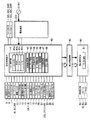
図4は、スロットマシン1の構成を示すブロック図である。スロットマシン1には、遊技制御基板40、演出制御基板90、電源基板101が設けられている。遊技制御基板40によって遊技状態が制御され、演出制御基板90によって遊技状態に応じた演出が制御され、電源基板101によってスロットマシン1を構成する電気部品の駆動電源が生成されて各部に供給される。
FIG. 4 is a block diagram showing a configuration of the
遊技制御基板40には、1枚BETスイッチ5、MAXBETスイッチ6、スタートスイッチ7、ストップスイッチ8L、8C、8R、精算スイッチ10、所定のキー操作により打止状態等を解除するためのリセット操作を検出するリセットスイッチ23、投入メダルセンサ31、リール2L、2C、2Rそれぞれに設けられたリール原点位置を検出するリールセンサ33L、33C、33Rが接続されている。
The
また、遊技制御基板40には、クレジット表示器11、遊技補助表示器12、ペイアウト表示器13、1〜3BETLED14〜16、投入要求LED17、スタート有効LED18、ウェイト中LED19、リプレイ中LED20、BETスイッチ有効LED21、左、中、右停止有効LED22L、22C、22R、メダル投入部4から投入されたメダルの流路を筐体1a内部に設けられた後述のホッパータンク側またはメダル払出口9側のいずれか一方に選択的に切り替えるための流路切替ソレノイド30、リールモータ32L、32C、32Rが接続されており、これら電気部品は、遊技制御基板40に搭載された後述のメイン制御部41の制御に基づいて駆動される。
In addition, the
遊技制御基板40には、メインCPU41a、ROM41b、RAM41c、I/Oポート41dを備えたマイクロコンピュータからなり、遊技の制御を行なうメイン制御部41、所定範囲(本実施の形態では0〜65535)の乱数を発生させる乱数発生回路42、乱数発生回路から乱数を取得するサンプリング回路43、遊技制御基板40に直接または電源基板101を介して接続されたスイッチ類から入力された検出信号を検出するスイッチ検出回路44、リールモータ32L、32C、32Rの駆動制御を行なうモータ駆動回路45、流路切替ソレノイド30の駆動制御を行なうソレノイド駆動回路46、遊技制御基板40に接続された各種表示器やLEDの駆動制御を行なうLED駆動回路47、電源投入時またはメインCPU41aからの初期化命令が入力されないときにメインCPU41aにリセット信号を与えるリセット回路48が搭載されている。ROM41bには、遊技制御用のプログラムや、リール停止制御に用いる各種のテーブルデータが格納されている。
The
乱数発生回路42は、後述するように所定数のパルスを発生する度にカウントアップして値を更新するカウンタによって構成され、サンプリング回路43は、乱数発生回路42がカウントしている数値を取得する。乱数発生回路42は、乱数の種類毎にカウントする数値の範囲が定められており、本実施の形態では、その範囲として0〜65535が定められている。メインCPU41aは、その処理に応じてサンプリング回路43に指示を送ることで、乱数発生回路42が示している数値を乱数として取得する(以下、この機能をハードウェア乱数機能という)。後述する内部抽選用の乱数は、ハードウェア乱数機能により抽出した乱数をそのまま使用するのではなく、ソフトウェアにより加工して使用する。
The random
なお、内部抽選用の乱数は、ハード回路(乱数発生回路42)のみによって生成してもよく、あるいは、ハード回路(乱数発生回路42)を用いずに、メイン制御部41が実行する遊技制御プログラム内でソフトウエア的に生成してもよい。
The random number for internal lottery may be generated only by a hardware circuit (random number generation circuit 42), or a game control program executed by the
また、メインCPU41aは、タイマ割込処理(メイン)により、特定のレジスタの数値を更新し、こうして更新された数値を乱数として取得する機能も有する(以下、この機能をソフトウェア乱数機能という)。
The
メインCPU41aは、I/Oポート41dを介して演出制御基板90に、各種のコマンドを送信する。遊技制御基板40から演出制御基板90へ送信されるコマンドは、演出中継基板80を介して一方向のみで演出制御基板90へ送られ、演出制御基板90から遊技制御基板40へ向けてコマンドが送られることはない。
The
演出制御基板90には、液晶表示器51、スピーカ52、53、リールLED54等の電気部品が接続されており、これら電気部品は、演出制御基板90に搭載されたサブ制御部91による制御に基づいて駆動される。
The
スロットマシン1においてゲームを行なう場合には、まず、メダルをメダル投入部4から投入するか、あるいはクレジット(持点)を使用して賭数を設定する。クレジットを使用するには1枚BETスイッチ5、またはMAXBETスイッチ6を操作すればよい。遊技状態に応じて定められた規定数の賭数が設定されると、入賞ラインL1〜L5(図1参照)のうち遊技状態に応じて定められた入賞ラインが有効となり、スタートスイッチ7の操作が有効な状態、すなわち、ゲームが開始可能な状態となる。遊技状態に対応する規定数を超えてメダルが投入された場合には、その分はクレジットに加算される。
When a game is played in the
入賞ラインは、各リール2L、2C、2Rの透視窓3に表示された図柄の組合せが入賞図柄の組合せであるかを判定するために設定されたラインである。本実施の形態では、図1に示すように、各リール2L、2C、2Rの中段に並んだ図柄に跨って設定された入賞ラインL1(中段ライン)、各リール2L、2C、2Rの上段に並んだ図柄に跨って設定された入賞ラインL2(上段ライン)、各リール2L、2C、2Rの下段に並んだ図柄に跨って設定された入賞ラインL3(下段ライン)、リール2Lの下段、リール2Cの中段、リール2Rの上段、すなわち右上がりに並んだ図柄に跨って設定された入賞ラインL4(右上がりライン)、リール2Lの上段、リール2Cの中段、リール2Rの下段、すなわち右下がりに並んだ図柄に跨って設定された入賞ラインL5(右下がりライン)の5種類が入賞ラインとして定められており、規定数の賭数が設定されると入賞ラインL1〜L5の全てが有効となる。
The winning line is a line that is set to determine whether the combination of symbols displayed on the
ゲームが開始可能な状態でスタートスイッチ7を操作すると、メイン制御部41によってスタート操作が検出される。スタート操作の検出に基づいて、メイン制御部41は各リール2L、2C、2Rを一斉に回転開始させる。これにより、各リール2L、2C、2Rの図柄が連続的に変動する。この状態でいずれかのストップスイッチ8L、8C、8Rを操作すると、対応するリール2L、2C、2Rの回転が停止し、停止したリールの図柄の表示結果が透視窓3に導出される。以下、ストップスイッチ8L、8C、8Rのいずれかの操作を“停止操作”と称する。
When the
全てのリール2L、2C、2Rの回転が停止して各リールの図柄の表示結果が導出されることで1ゲームが終了する。なお、本実施の形態では、各リールの図柄の表示結果が導出されたときには、対応するリールが完全に停止する。しかしながら、これに変えて、リールの回転が停止して図柄の表示結果が導出されたときでも、リールが上下方向に振動するように動くようにしてもよい。その場合、全リールの回転が停止して全リールの図柄の表示結果が導出されたときには、各リールの振動動作を停止させてもよく、あるいは、各リールの振動動作を継続させてもよい。
The rotation of all the
全リールの図柄の表示結果が導出されたときに、有効化されているいずれかの入賞ラインL1〜L5上に予め定められた図柄の組合せが各リール2L、2C、2Rの表示結果として停止した場合には入賞が発生する。入賞が発生すると、その入賞に応じて定められた大きさの遊技価値が遊技者に付与される(規定枚数のメダルの払出し、あるいはこれに対応する数のクレジット加算)。
When the display results of the symbols for all reels are derived, the combination of symbols predetermined on any of the activated pay lines L1 to L5 is stopped as the display result of each
なお、有効化された複数の入賞ライン上にメダルの払出を伴う図柄の組合せが揃った場合には、有効化された入賞ラインに揃った図柄の組合せそれぞれに対して定められた払出枚数を合計し、合計した枚数のメダルが遊技者に対して付与される。 If a combination of symbols with payout of medals is arranged on a plurality of activated pay lines, the total number of payouts determined for each combination of symbols arranged on the activated pay line is totaled. The total number of medals is awarded to the player.
ただし、1ゲームで付与されるメダルあるいはクレジットの付与数には、上限(本実施の形態では、15)が定められており、合計数が上限を超える場合には、上限数のクレジットまたはメダルが遊技者に付与される。また、有効化されたいずれかの入賞ラインL1〜L5上に、遊技状態の移行を伴う図柄の組合せ(ビッグボーナス)が各リール2L、2C、2Rの表示結果として停止した場合には図柄の組合せに応じた遊技状態に移行する。
However, an upper limit (15 in the present embodiment) is set for the number of medals or credits awarded in one game, and when the total number exceeds the upper limit, the upper limit number of credits or medals is It is given to the player. In addition, on any of the activated pay lines L1 to L5, if a combination of symbols (big bonus) accompanied by a transition of the gaming state stops as a display result of each
本実施の形態のスロットマシン1においては、可変表示装置2のいずれかの入賞ライン上に予め定めた図柄の組合せが揃うと、入賞となる。
In the
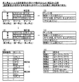
図3は、入賞役の種類、入賞役の図柄組合せ、および入賞役に関連する技術事項について説明するための図である。入賞役は、入賞となる役の種類は、遊技状態に応じて定められているが、入賞の発生により特別遊技(ビッグボーナス)に移行する特別役と、特別遊技への移行がなくメダルの払出しがある小役と、新たな投資を必要とすることなく再ゲームが可能とされる再遊技役とに大別される。また、小役と再遊技役とを併せて一般役とも称する。 FIG. 3 is a diagram for explaining the types of winning combinations, symbol combinations of winning combinations, and technical matters related to winning combinations. As for the winning combination, the type of winning combination is determined according to the game status, but the special combination that shifts to the special game (big bonus) by the occurrence of the winning, and the medal payout without the transition to the special game A small role is roughly divided into a replay player who can re-game without requiring a new investment. The small combination and the replay combination are also referred to as a general combination.
なお、ビッグボーナスをBBと表記し、ビッグボーナス中に提供されるレギュラーボーナスをRBと表記する場合がある。また、ビッグボーナス、レギュラーボーナスを単にボーナスという場合もある。さらに、ビッグボーナスを特別遊技状態ともいう。いずれにしても、遊技状態に応じて定められた各役の入賞が発生するためには、内部抽選に当選し、当該入賞役に対応する当選フラグがRAM41cに設定されている必要がある。
In some cases, the big bonus is denoted as BB, and the regular bonus provided during the big bonus is denoted as RB. In some cases, a big bonus or a regular bonus is simply referred to as a bonus. Furthermore, the big bonus is also called a special game state. In any case, in order to win each winning combination determined according to the gaming state, it is necessary to win the internal lottery and set a winning flag corresponding to the winning winning combination in the
特別役には、ビッグボーナス1(BB1とも称する)、ビッグボーナス(BB2とも称する)、ビッグボーナス3(BB3とも称する)が含まれる。小役には、イチゴ、ブドウ、メロン、特殊1〜6が含まれる。再遊技役には、再遊技1,2が含まれる。内部抽選は、これらの入賞役別に行なわれ、入賞役別に当選フラグが設定される。 The special combination includes a big bonus 1 (also referred to as BB1), a big bonus (also referred to as BB2), and a big bonus 3 (also referred to as BB3). Small roles include strawberries, grapes, melons, and special 1-6. The re-games include re-games 1 and 2. The internal lottery is performed for each winning combination, and a winning flag is set for each winning combination.
ビッグボーナス1に対応する入賞ラインの図柄の組合せは、「赤7−赤7−赤7」である。ビッグボーナス2に対応する入賞ラインの図柄の組合せは、「白7−白7−白7」である。ビッグボーナス3に対応する入賞ラインの図柄の組合せは、「BAR−BAR−BAR」である。ビッグボーナス1〜3のうちいずれかに入賞すると、遊技状態が遊技者にとって有利な遊技状態(特別遊技状態)であるビッグボーナスに移行する。
The combination of the winning line symbols corresponding to the
ビッグボーナスに制御されているときには、当該ビッグボーナスが終了するまで、レギュラーボーナス(RBとも称する)に繰り返し制御される。レギュラーボーナス中は、たとえば、所定役(たとえば、「イチゴ」、「ブドウ」、「メロン」、「特殊1〜6」の全小役。あるいはこれらのいずれか1つあるいは複数の役であってもよい。)の当選確率がそれ以外の遊技状態のときよりも向上される。レギュラーボーナスは、所定のRB終了条件(たとえば、12ゲーム消化するかまたは8回入賞等)が成立したときに終了する。 When controlled to a big bonus, it is repeatedly controlled to a regular bonus (also referred to as RB) until the big bonus ends. During the regular bonus, for example, a predetermined combination (for example, all the small combinations of “strawberry”, “grape”, “melon”, “special 1 to 6”, or any one or more of these combinations may be used. The probability of winning is better than in other gaming states. The regular bonus ends when a predetermined RB end condition (for example, 12 games have been consumed or 8 wins are won).
遊技状態がビッグボーナスにある間は、入賞したビッグボーナス1〜3の種類に対応するビッグボーナス中フラグがRAM41cに設定される。また、レギュラーボーナスにある間は、レギュラーボーナス中フラグがRAM41cに設定される。すなわち、ビッグボーナス中フラグがON状態に設定されている間は、ゲームが開始されるときにレギュラーボーナス中フラグがON状態に設定されていないときに、繰り返しレギュラーボーナス中フラグがON状態に設定される。
While the gaming state is the big bonus, a big bonus medium flag corresponding to the types of the
ビッグボーナス1〜3は、予め定めたBB終了条件(たとえば、遊技者に払い出したメダルの枚数が規定枚数に達したこと、その他、所定期間の経過等であってもよい)が成立したときに終了する。
The
なお、ビッグボーナス1〜3の終了条件は、共通であってもよく、それぞれに異なる終了条件を設定してもよい。また、本実施の形態では、ビッグボーナス1〜3のいずれに入賞したときでも、移行するビッグボーナスは同じであるが、ビッグボーナス1〜3の種類によって、ビッグボーナスの遊技内容を異なるものとしてもよい。たとえば、ビッグボーナス1〜3の種類によって、賭数を異ならせたり、最大払出し枚数を異ならせたりすることが考えられる。
Note that the end conditions of the
次に、小役について説明する。小役は、入賞時のメダルの払出数に応じて、1枚役、2枚役、5枚役、15枚役に分類される。 Next, a small role will be described. The small combination is classified into one combination, two combination, five combination, and 15 combination according to the number of medals paid out at the time of winning a prize.
1枚役は、「イチゴ」、および「特殊4〜6」である。「イチゴ」に対応する入賞ラインの図柄の組合せは、「赤7−any−any」である。ここで、「any」は、いずれの図柄であってもよいことを意味する。つまり、「赤7−any−any」は、左リールの上段中段下段のいずれかに「赤7」が停止すれば、中リールおよび右リールの停止図柄の種類に関わらず「イチゴ」の入賞が発生することを意味する。特殊4〜6の各々に対応する入賞ラインの図柄の組合せは、各々、「赤7−イチゴ−イチゴ」、「白7−イチゴ−イチゴ」、「BAR−イチゴ−イチゴ」である。
The single role is “strawberry” and “special 4-6”. The winning line symbol combination corresponding to “strawberry” is “red 7-any-any”. Here, “any” means that any symbol may be used. In other words, “Red 7-any-any” means that if “
2枚役は、「ブドウ」である。ブドウに対応する入賞ラインの図柄の組合せは、「ブドウ(図3では“ブド”と表記)−ブドウ−any」である。「ブドウ−ブドウ−any」は、左および中リールの入賞ラインのいずれかに「ブドウ」が揃って停止すれば、右リールの停止図柄の種類に関わらず「ブドウ」の入賞が発生することを意味する。 The two-piece role is “Grape”. The combination of symbols of the winning line corresponding to the grape is “Grape (denoted as“ Budo ”in FIG. 3) -Grape-any”. “Grape-Grape-any” means that if “Grape” stops on either the left or middle reel winning line, the “Grape” winning will occur regardless of the type of stop symbol on the right reel. means.
5枚役は、「メロン」である。メロンに対応する入賞ラインの図柄の組合せは、「メロン−メロン−メロン」である。 The five-piece role is “melon”. The combination of the winning line symbols corresponding to the melon is “melon-melon-melon”.
15枚役は、「特殊1〜3」である。特殊1〜3の各々に対応する入賞ラインの図柄の組合せは、各々、「赤7−ブドウ−ブドウ」、「白7−ブドウ−ブドウ」、「BAR−ブドウ−ブドウ」である。 The 15-card combination is “Special 1 to 3”. The combinations of the winning line symbols corresponding to each of the special 1 to 3 are “red 7-grape-grape”, “white 7-grape-grape”, and “BAR-grape-grape”, respectively.
次に、再遊技役について説明する。再遊技役には、再遊技1と再遊技2とがある。再遊技役1,2のいずれかに入賞したときには、メダルの払い出しはないが次のゲームを改めて賭数を設定することなく開始できるので、次のゲームで設定不要となった賭数に対応した枚数分のメダルが払い出されるのと実質的には同じこととなる。
Next, the re-game player will be described. There are two types of re-games: re-game 1 and
再遊技1,2の各々に対応する入賞ラインの図柄の組合せは、各々、「リプレイ(図3では“リプ”と表記)−リプレイ−リプレイ」、「特7−リプレイ−リプレイ」である。
The combinations of the winning line symbols corresponding to each of the
次に、リールの停止制御について説明する。ストップスイッチ8L、8C、8Rの操作から対応するリール2L、2C、2Rの回転を停止するまでの最大停止遅延時間は、たとえば、190ms(ミリ秒)である。リール2L、2C、2Rは、1分間に80回転するため、この間に80×21(1リール当たりの図柄コマ数)=1680コマ分の図柄が変動することになる。
Next, reel stop control will be described. The maximum stop delay time from the operation of the stop switches 8L, 8C, 8R to the stop of rotation of the corresponding
それゆえ、最大停止遅延時間(190ms)では、最大で4コマの図柄を滑らせることができる。つまり、停止図柄として選択可能なのは、ストップスイッチ8L、8C、8Rが操作されたときに表示されている図柄と、そこから4コマ先までにある図柄の合計5コマ分の図柄である。 Therefore, at the maximum stop delay time (190 ms), it is possible to slide up to 4 symbols. That is, the symbols that can be selected as the stop symbols are the symbols for a total of five frames, that is, the symbols displayed when the stop switches 8L, 8C, and 8R are operated and the symbols that are four frames ahead.
たとえば、ストップスイッチ8L、8C、8Rのいずれかの操作が検出されたときに当該ストップスイッチに対応するリールの中段位置を基準位置とした場合、基準位置に表示されている図柄から4コマ先までの図柄をリールの中段に引き込んで(滑らせて)停止させることができる。 For example, if the middle position of the reel corresponding to the stop switch when the operation of any one of the stop switches 8L, 8C, 8R is detected as the reference position, from the symbol displayed at the reference position to 4 frames ahead Can be pulled into the middle of the reel (sliding) and stopped.
本実施の形態では、可変表示装置の中段位置(中段の入賞ラインの位置)を“基準位置”としている。また、停止操作が検出されたときに基準位置にある図柄を含んで図柄停止に至るまでに送った図柄数を“滑りコマ数”と称し、停止操作が検出されたときに基準位置にある図柄で停止させた場合の滑りコマ数は、“0”とする。さらに、引き込み可能な最大コマ数(たとえば、停止操作検出時に基準位置にある図柄を除くと4コマ、基準位置にある図柄を入れて5コマ)を“最大滑りコマ数”と称する。 In the present embodiment, the middle position of the variable display device (the position of the middle winning line) is set as the “reference position”. The number of symbols sent to the symbol stop including the symbol at the reference position when the stop operation is detected is referred to as the “slip frame number”, and the symbol at the reference position when the stop operation is detected. The number of sliding frames when stopped at is “0”. Furthermore, the maximum number of frames that can be pulled in (for example, 4 frames if the symbols at the reference position are removed when detecting a stop operation, and 5 frames including the symbols at the reference position) is referred to as the “maximum number of sliding frames”.
ここで、図2に示されるように、図柄の「リプレイ」は、各リール2L、2C、2Rにおいて、必ず5図柄以内に1つ配列されている(左リール2Lについてはさらに図柄番号19に「特7」が配列)。これにより、どのようなタイミングで停止操作をしても必ず「再遊技1,2」の入賞役による入賞を発生させることができ、その結果、「再遊技1,2」が内部当選している場合の当該役に対応する図柄の取りこぼしを防止することで単位時間あたりの遊技者の投資額を適度に抑えて射倖性が極端に高まり過ぎることを防止できる。
Here, as shown in FIG. 2, the symbol “replay” is always arranged within 5 symbols in each
なお、基準位置は、可変表示装置の中段位置に限定されるものではなく、可変表示装置の上段位置としても、下段位置としてもよい。あるいは、可変表示装置の上中下三段のいずれかの位置に限定されるものではなく、可変表示装置のリールに配列された各図柄の可変表示部に対する位置を特定できる箇所であれば、いずれの箇所を基準位置としてもよい。 Note that the reference position is not limited to the middle position of the variable display device, and may be the upper position or the lower position of the variable display device. Alternatively, the position is not limited to any one of the upper, middle, and lower three positions of the variable display device, as long as the position can be specified with respect to the variable display portion of each symbol arranged on the reel of the variable display device. These locations may be used as the reference position.
ストップスイッチ8L、8C、8Rのうち、回転中のリールに対応する停止操作が検出されると、停止操作を検出した時点のリール原点位置からのステップ数に基づいて、基準位置(可変表示装置の中段)に位置する図柄の図柄番号が特定される。 When a stop operation corresponding to the rotating reel is detected among the stop switches 8L, 8C, 8R, the reference position (of the variable display device) is determined based on the number of steps from the reel origin position at the time when the stop operation is detected. The symbol number of the symbol located in the middle stage is specified.
次に、特定した図柄番号に対応する滑りコマ数が、滑りコマ数テーブルから取得される。滑りコマ数テーブルは、たとえば、図15に示されるように、各リールに対応して、図柄番号別に滑りコマ数を規定したデータである。メイン制御部41は、滑りコマ数テーブルを参照することで、停止させるリールの基準位置に位置する図柄の図柄番号に対応する滑りコマ数を取得する。
Next, the number of sliding symbols corresponding to the specified symbol number is acquired from the number of sliding symbols table. For example, as shown in FIG. 15, the sliding frame number table is data defining the number of sliding frames for each symbol number corresponding to each reel. The
続いて、メイン制御部41は、停止操作を検出した時点で基準位置にある図柄を滑りコマ数分だけ滑らせて(滑りコマ数分だけリールを回転させて)停止させる制御を行なう。これにより、停止操作が検出されたときに基準位置に位置する図柄から滑りコマ数テーブルに従う滑りコマ数だけ移動した図柄番号に対応する図柄が基準位置(可変表示装置の中段)に停止する。
Subsequently, the
図5は、全リールの回転開始から全リールの回転停止までにメイン制御部41(図4参照)によって仮想的に設定される、第一停止リール〜第三停止リールと、左、中、右リール(リール2L、2C、2R)との対応関係を示す図である。 FIG. 5 shows the first to third stop reels, left, middle and right virtually set by the main control unit 41 (see FIG. 4) from the start of rotation of all reels to the stop of rotation of all reels. It is a figure which shows the correspondence with a reel (reel 2L, 2C, 2R).
図5を参照して、1ゲームの開始によって回転を開始した左、中、右リール(リール2L、2C、2R)は、ストップスイッチ8L、8C、8Rが任意の順序で操作されることに基づいて停止する。
Referring to FIG. 5, the left, middle, and right reels (
以下では、1ゲーム開始後、3つのリールのうちの1つ目のリールを停止させるための停止操作を“第一停止操作”、2つ目のリールを停止させるための停止操作を“第二停止操作”、3つ目のリールを停止させるための操作を“第三停止操作”と称する。 In the following, after the start of one game, a stop operation for stopping the first reel of the three reels is referred to as “first stop operation”, and a stop operation for stopping the second reel is referred to as “second stop”. The operation for stopping the third reel is referred to as a “third stop operation”.
また、第一停止操作で停止するリールを“第一停止リール”、第二停止操作で停止するリールを“第二停止リール”、第三停止操作で停止するリールを“第三停止リール”と称する。 Also, the reel that stops by the first stop operation is called “first stop reel”, the reel that stops by the second stop operation is “second stop reel”, and the reel that stops by the third stop operation is called “third stop reel”. Called.
メイン制御部41は、1ゲーム開始後、第一停止操作が検出される前の段階で、仮想的に、第一停止リールを左リール2L、第二停止リールを中リール2C、第三停止リールを右リール2Rと設定する。その上で、メイン制御部41は、後述する手順によって第一〜第三停止リールに対応する滑りコマ数テーブルを用意する。
The
スロットマシン1は、第一停止操作に応じた各リールの滑りコマ数テーブルを予め複数種類記憶しており、第一停止操作前に滑りコマ数テーブルを選択して停止制御に用いる。しかし、第二停止操作あるいは第三停止操作に応じた各リールの滑りコマ数テーブルについては記憶しておらず、第一停止操作の検出によって停止した第一停止リールの停止結果に応じて、さらには第二停止操作の検出によって停止した第二停止リールの停止結果に応じて、夫々、滑りコマ数テーブルをその都度、作成する。
The
第一停止操作に備えて第一〜第三停止リールを仮想的に設定した後、設定した第一停止リールと異なるリールに対応する第一停止操作が検出されたときには、検出された第一停止操作に対応する種類のリールに対して用意した滑りコマ数テーブルをそのまま用いてリールの停止制御を行なう。 After the first to third stop reels are virtually set in preparation for the first stop operation, when a first stop operation corresponding to a reel different from the set first stop reel is detected, the detected first stop The reel stop control is performed using the sliding frame number table prepared for the type of reel corresponding to the operation as it is.
たとえば、第一停止操作が、第三停止リールとして仮想的に設定した右リール2Rに対応するものであったときには、右リール2R用(第三停止リール)に用意した滑りコマ数テーブルをそのまま用いて右リール2Rを停止させる。このような場合には、第一停止前に仮想的に設定した第一〜第三停止リールの組合せに変更が生じる。
For example, when the first stop operation corresponds to the
そこで、第一停止操作の検出後、第二停止操作の検出前に、第二、第三停止リールを再設定する。この場合、図5に示されるように、第一停止リールが左リールであるか中リールであるか右リールであるかによって、第二、第三停止リールの設定が異なってくる。 Therefore, the second and third stop reels are reset after the detection of the first stop operation and before the detection of the second stop operation. In this case, as shown in FIG. 5, the settings of the second and third stop reels differ depending on whether the first stop reel is the left reel, the middle reel, or the right reel.
図5に示されるように、第一停止リールが左のときは、第二停止リールを中、第三停止リールを右に設定し、第一停止リールが中のときは、第二停止リールを左、第三停止リールを右に設定し、第一停止リールが右のときは、第二停止リールを左、第三停止リールを中に設定する。ただし、第二停止操作の検出前であるので、いずれも仮想的な設定になる。 As shown in FIG. 5, when the first stop reel is on the left, the second stop reel is set to the middle and the third stop reel is set to the right. When the first stop reel is on, the second stop reel is set to the right. The left and third stop reels are set to the right, and when the first stop reel is right, the second stop reel is set to the left and the third stop reel is set to the inside. However, since it is before the detection of the second stop operation, both are virtual settings.
第二、第三停止リールを仮想的に設定した後、メイン制御部41は、後述する手順によって第二、第三停止リールに対応する滑りコマ数テーブルを作成する。
After virtually setting the second and third stop reels, the
その後、仮想的に設定した第二停止リールと異なるリールに対応する第二停止操作が検出されたときには、第一停止操作が検出されたときと同様に、検出された第二停止操作に対応する種類のリールに対して用意した滑りコマ数テーブルをそのまま用いてリールの停止制御を行なう。このような場合には、第二停止前に仮想的に設定した第二、第三停止リールの組合せに変更が生じる。 Thereafter, when a second stop operation corresponding to a reel different from the virtually set second stop reel is detected, the detected second stop operation is handled in the same manner as when the first stop operation is detected. Reel stop control is performed using the sliding frame number table prepared for each type of reel as it is. In such a case, the combination of the second and third stop reels virtually set before the second stop is changed.
そこで、第二停止操作の検出後、第三停止操作の検出前に、第三停止リールを再設定する。この場合、図5に示されるように、第一停止リールおよび第二停止リールの種類によって第三停止リールの設定が異なる。この場合、残る未停止リールは1つであるので、第三停止リールの設定は、確定的な設定になる。 Therefore, the third stop reel is reset after the second stop operation is detected and before the third stop operation is detected. In this case, as shown in FIG. 5, the setting of the third stop reel differs depending on the types of the first stop reel and the second stop reel. In this case, since there is only one remaining non-stop reel, the setting of the third stop reel is a definitive setting.
第三停止リールを設定した後、メイン制御部41は、後述する手順によって第三停止リールに対応する滑りコマ数テーブルを作成し直し、第三停止操作に応じて、作成し直した滑りコマ数テーブルに基づいて第三停止リールを停止させる。
After setting the third stop reel, the
このように、本実施の形態に係るスロットマシン1は、第一停止操作検出前に、第一停止〜第三停止リールを仮決めするため、停止操作に備えた停止制御を極力簡単にすることができる。
Thus, since the
図6は、リールの停止制御に関するメインフローである。また、図7〜図11は、このメインフローのサブルーチンを示すフローチャートである。さらに、図12〜図21は、リールの停止制御に用いられる各種データを説明するための図である。以下では、これらの図面を用いて、リールの停止制御を詳細に説明する。なお、図6〜11に示される処理は、図4に示したメイン制御部41が実行する。
[メインフローのS1〜S5]
図6のメインフローに従って、必要に応じて図7〜図21を参照しつつ、リールの停止制御を説明する。まず、スタートスイッチ7が操作されることに基づいて、スタート操作が検出される(S1)。次に、内部抽選処理が実行される(S2)。また、スタート操作の検出に基づいて、リール2L、2C、2Rの変動(回転)が開始される。
FIG. 6 is a main flow relating to reel stop control. 7 to 11 are flowcharts showing a subroutine of the main flow. 12 to 21 are diagrams for explaining various data used for reel stop control. Hereinafter, the reel stop control will be described in detail with reference to these drawings. The processing shown in FIGS. 6 to 11 is executed by the
[S1-S5 of main flow]
The reel stop control will be described according to the main flow of FIG. 6 with reference to FIGS. 7 to 21 as necessary. First, a start operation is detected based on the operation of the start switch 7 (S1). Next, an internal lottery process is executed (S2). Further, the fluctuation (rotation) of the
S2の内部抽選処理について詳細に説明する。内部抽選とは、入賞の発生(入賞表示結果の導出)を許容するか否かを、可変表示装置2の表示結果が導出表示される以前に(実際には、スタートスイッチ7の操作検出時に)決定することである。
The internal lottery process in S2 will be described in detail. In the internal lottery, whether or not winning is permitted (derivation of the winning display result) is determined before the display result of the
内部抽選では、まず、乱数発生回路42から内部抽選用の乱数(0〜65535の整数)が取得される。次に、遊技状態に応じて定められた抽選対象役の組合せについて、取得した内部抽選用の乱数と、遊技状態、賭数および設定値に応じて定められた各役および役の組合せの当選値とが判定される。判定の結果、当選ありとなったときには、当選した役に対応する当選フラグが設定される。この当選フラグは、1ゲームが終了する毎に消去される。ただし、ビッグボーナス当選フラグについては、ビッグボーナス入賞が発生するまで、次回のゲームに持ち越される。RAM41cにより、当選フラグを記憶する当選フラグ記憶手段が構成されている。
In the internal lottery, first, a random number for internal lottery (an integer from 0 to 65535) is acquired from the random
本実施の形態においては、当選値の一部またはすべてが重複して設定された入賞役が存在する。このため、1ゲームにおいて複数種類の役が同時に当選することがあり得る。 In the present embodiment, there is a winning combination in which some or all of the winning values are set redundantly. For this reason, a plurality of types of winning combinations may be won simultaneously in one game.
たとえば、一般遊技では、「イチゴ」の当選値の一部と「特殊4」の当選値の一部とが重複しており、かつ、その重複部分において「特殊5」の当選値の一部が重複している。このため、乱数発生回路42から抽出された抽選値がその重複部分の当選値と一致するときには、それら3つの役が同時当選する。
For example, in a general game, a part of the winning value of “strawberry” and a part of the winning value of “special 4” overlap, and a part of the winning value of “special 5” is overlapped in the overlapping part. Duplicate. For this reason, when the lottery value extracted from the random
また、一般遊技では、「再遊技1,2」の双方の当選値が共通しており、同様に、「特殊1,2」の双方の当選値が共通している。このため、「再遊技1,2」、および「特殊1,2」は、それぞれ同時当選する。
In the general game, the winning values of both “
さらに、一般遊技では、「ブドウ」の当選値の一部と「特殊6」の当選値の一部とが重複しており、抽選値がその重複部分の当選値と一致するときには、「ブドウ」と「特殊6」とが同時当選する。 Furthermore, in the general game, when a part of the winning value of “Grape” and a part of the winning value of “Special 6” overlap, and the lottery value matches the winning value of the overlapping part, “Grape” And “Special 6” are won simultaneously.
一方、ビッグボーナスの特別遊技では、「イチゴ」、「ブドウ」、「特殊1〜6」のすべての当選値が共通であり、「メロン」のみ当選値が異なるため、「イチゴ」、「ブドウ」、および「特殊1〜6」のすべてが同時当選した状態か、メロンのみが当選した状態、あるいは外れの状態となる。なお、特別遊技中は、リプレイおよびビッグボーナスは抽選されない。 On the other hand, in the special game of the big bonus, all the winning values of “strawberry”, “grape”, and “special 1-6” are common, and the winning value is different only for “melon”, so “strawberry”, “grape” , And “special 1 to 6” are all won at the same time, only the melon is won, or are in a state of losing. During special games, replays and big bonuses are not drawn.
以上より、特別遊技中に内部抽選の結果、設定される当選フラグ(の組合せ)は、図12(A)に示されるように、[イチゴ、ブドウ、特殊1〜6]または[メロン]のいずれかになる。 As described above, the winning flag (combination) set as a result of the internal lottery during the special game is any one of [strawberry, grape, special 1-6] or [melon] as shown in FIG. It becomes.
また、一般遊技中に内部抽選の結果、設定される当選フラグ(の組合せ)は、ビッグボーナス当選フラグの持越しを考慮すると、図12(B)に示されるように、[再遊技1,2]、[イチゴ]、[ブドウ]、[イチゴ、特殊4、特殊5]、[ブドウ、特殊6]、[特殊3]、[特殊1、特殊2]、[メロン]、[特殊6]、[特殊5]、[特殊4]、さらには、それらと[BB1]、[BB2]、[BB3]の組合せのいずかである。 In addition, the winning flag (combination) set as a result of the internal lottery during the general game takes into account the carry-over of the big bonus winning flag, as shown in FIG. , [Strawberry], [grape], [strawberry, special 4, special 5], [grape, special 6], [special 3], [special 1, special 2], [melon], [special 6], [special 5], [Special 4], and a combination of them with [BB1], [BB2], and [BB3].
S2の内部抽選処理の後、遊技状態(特別遊技中か一般遊技中か)、持越しフラグの有無、およびS2による当選状況が判別される(S3)。そして、S3の判別結果に基づいて、第一停止前の滑りコマ数テーブルを作成するための第一停止時テーブルが選択される(S4)。 After the internal lottery process of S2, the game state (whether special game or general game), presence / absence of carryover flag, and winning status by S2 are determined (S3). Then, based on the determination result of S3, the first stop time table for creating the sliding frame number table before the first stop is selected (S4).
具体的には、図12(A)、(B)に示されるような、第一停止時テーブル番号検索用データに基づいて、遊技状態(特別遊技中か一般遊技中か)、持越しフラグの有無、および当選状況に応じた第一停止時テーブル番号が検索され、対応する番号の第一停止時テーブルが選択される。 Specifically, based on the first stop table number search data as shown in FIGS. 12 (A) and 12 (B), the gaming state (whether special game or general game is in progress) and the presence of a carryover flag The first stop table number corresponding to the winning situation is retrieved, and the first stop table corresponding to the corresponding number is selected.
たとえば、遊技状態が特別遊技で、当選状況(S2)が外れのときには、図12(A)に示される第一停止時テーブル番号「0」が検索され、対応する番号の第一停止時テーブル0が選択される。遊技状態が一般遊技で、当選状況(S2)が外れのとき、持越し当選フラグが存在しなければ、図12(B)に示される第一停止時テーブル番号「3」が検索され、対応する番号の第一停止時テーブル3が選択される。 For example, when the gaming state is a special game and the winning situation (S2) is out, the first stop table number “0” shown in FIG. 12A is retrieved, and the first stop table 0 of the corresponding number is searched. Is selected. When the game state is a general game and the winning situation (S2) is out, if there is no carry-over winning flag, the first stop table number “3” shown in FIG. 12B is searched and the corresponding number is searched. The first stop time table 3 is selected.
図13には、第一停止時テーブルの例が示されている。メイン制御部41には、番号0〜番号50までの合計51の第一停止時テーブルが予め記憶されている。第一停止時テーブルには、各リール2L、2C、2Rに配列された図柄の図柄番号に対応する滑りコマ数のデータが、左中右のリール順および図柄番号0〜20の順に羅列されており、その一部がデータ圧縮されている。
FIG. 13 shows an example of the first stop table. In the
そこで、S5では、選択された第一停止時テーブルに基づいて第一〜第三停止リール別に滑りコマ数テーブルを作成するための「第一停止用滑りコマ数テーブル作成処理」が実行される。ここで、図7を参照して、「第一停止用滑りコマ数テーブル作成処理」を説明する。
[第一停止用滑りコマ数テーブル作成処理]
図7は、第一停止用滑りコマ数テーブル作成処理を説明するためのフローチャートである。第一停止用滑りコマ数テーブル作成処理は、図6のメインフローのS5で実行されるサブルーチンである。
Therefore, in S5, a “first stop sliding frame number table creation process” for creating a sliding frame number table for each of the first to third stop reels based on the selected first stop table is executed. Here, the “first stop sliding frame number table creation process” will be described with reference to FIG. 7.
[First stop sliding frame number table creation process]
FIG. 7 is a flowchart for explaining the first stop sliding frame number table creation process. The first stop sliding frame number table creation process is a subroutine executed in S5 of the main flow of FIG.
第一停止用滑りコマ数テーブル作成処理は、選択された第一停止時テーブルのデータの先頭から単位データ分のデータを順番に読み出し、読み出したデータを第一〜第三停止リールの各図柄の滑りコマ数として順番に設定する処理である。 The first stop sliding frame number table creation process reads data for unit data in order from the top of the data of the selected first stop table, and reads the read data for each symbol of the first to third stop reels. This is a process of setting the number of sliding frames in order.
設定順序は、仮想的に設定された第一停止リール(リール2L)、第二停止リール(リール2C)、第三停止リール(リール2R)の順である。また、滑りコマ数を格納する領域としては、第一〜第三停止リール用に第一〜第三停止用領域が用意されている。第一〜第三停止用領域の各々には、リールの図柄番号0〜20に対応する21の格納領域が設けられており、各格納領域の先頭から順に第一停止時テーブルの単位データ分のデータが格納されていくことによって、第一〜第三停止用領域に滑りコマ数テーブルが作成される。
The setting order is the first stop reel (reel 2L), second stop reel (reel 2C), and third stop reel (reel 2R) set virtually. In addition, as the area for storing the number of sliding frames, first to third stop areas are prepared for the first to third stop reels. Each of the first to third stop areas is provided with 21 storage areas corresponding to the
以下、フローチャートに基づいて、第一停止用滑りコマ数テーブル作成処理を説明する。最初に、読出す単位データの番号が0に初期化される(S21)。次に、単位データnのデータが第一停止時テーブルから読出される(S22)。たとえば、図13に示される第一停止時テーブル0の場合の単位データ0のデータは先頭の「2」であり、単位データ1のデータは後続の「A」であり、単位データ2のデータはさらに後続の「C」である。
The first stop sliding frame number table creation process will be described below based on the flowchart. First, the unit data number to be read is initialized to 0 (S21). Next, the data of the unit data n is read from the first stop table (S22). For example, in the case of the first stop time table 0 shown in FIG. 13, the data of the
次に、読出されたデータが「5」以下であるか否かが判断され(S23)、YESの場合には、その読出されたデータがそのまま滑りコマ数データとして格納される。この場合、このデータを格納する領域を検索するために、最初に第一停止用領域へは格納済みであるか否かが判断される(S24)。 Next, it is determined whether or not the read data is “5” or less (S23). If YES, the read data is stored as it is as the sliding frame number data. In this case, in order to search an area for storing this data, it is first determined whether or not the first stop area has been stored (S24).
第一停止用領域の格納領域0〜21のすべてにデータを格納済みの場合にはS28に進み、同様に、第二停止用領域へは格納済みであるか否かが判断され、第二停止用領域の格納領域0〜21のすべてにデータを格納済みの場合にはS30に進み、同様に、第三停止用領域へは格納済みであるか否かが判断される。そして、第三停止用領域の格納領域0〜21のすべてにデータを格納済みの場合には、第一〜第三停止リール用の滑りコマ数テーブルが完成しているため、データを格納することなく処理を終える。
If the data has already been stored in all the
たとえば、S24で第一停止用領域へ格納済みでないと判断されると、第一停止用領域のデータを格納していない格納領域のうち、最も若い番号の格納領域へデータが格納される。S24で第一停止用領域へ格納済みと判断されてS28で第二停止用領域へ格納済みでないと判断されたとき、あるいはS28で第二停止用領域へ格納済みと判断されてS30で第三停止用領域へ格納済みでないと判断されたときも同様に、未格納の格納領域のうち最も若い番号の格納領域へデータが格納される。 For example, if it is determined in S24 that the data has not been stored in the first stop area, the data is stored in the storage area with the lowest number among the storage areas not storing the data in the first stop area. When it is determined in S24 that it has been stored in the first stop area and it is determined in S28 that it has not been stored in the second stop area, or in S28 it is determined that it has been stored in the second stop area, and in S30, the third stop area is stored. Similarly, when it is determined that it has not been stored in the stop area, data is stored in the storage area with the lowest number among the unstored storage areas.
S25、S29、S31のいずれかでデータが格納されたときには、nが+1されて(S26)、再びS22に戻り、第一停止時テーブルの次の単位データが読出される。もし、S22で読出されたデータが5以上のときには、すなわち、圧縮されたデータであるので、変換用テーブルを用いてデータ変換する処理が実行される(S27)。 When data is stored in any one of S25, S29, and S31, n is incremented by 1 (S26), the process returns to S22 again, and the next unit data in the first stop table is read. If the data read in S22 is 5 or more, that is, since the data is compressed, the data conversion process is executed using the conversion table (S27).
図14に変換用テーブルの例を示す。図14において、「変換対象データ」は、第一停止用テーブルから読出されたデータである。また、「変換後データ」は、第一停止用テーブルから読出されたデータを変換したデータである。 FIG. 14 shows an example of the conversion table. In FIG. 14, “conversion object data” is data read from the first stop table. Further, “post-conversion data” is data obtained by converting the data read from the first stop table.
たとえば、第一停止用テーブルから読出されたデータが「5」の場合には、S27によって、「3、2、1、0、3、2、1、0」の滑りコマ数データに変換される。たとえば、第一停止用領域のすべての格納領域にデータが格納されていない場合には、S24にてNOと判断されて、S25において、データを未格納の格納領域の先頭から順に、「4」、「2」、「1」…の滑りコマ数データが格納される。なお、仮に、変換後データの各々を格納領域へ格納していく途中で、最後の格納領域へのデータ格納を終えた場合には、その第一停止用領域へのデータ格納が終了したと判断されて、第二停止用領域へのデータ格納処理(S29)に移行し、変換後データの後半部分は、第二停止用領域へ順次格納される。 For example, when the data read from the first stop table is “5”, it is converted into the sliding frame number data “3, 2, 1, 0, 3, 2, 1, 0” by S27. . For example, if data is not stored in all the storage areas of the first stop area, it is determined NO in S24, and in S25, “4” in order from the top of the storage area where data is not stored. , “2”, “1”... Are stored. In the meantime, if data storage in the last storage area is completed while each piece of converted data is being stored in the storage area, it is determined that data storage in the first stop area has been completed. Then, the process proceeds to data storage processing (S29) in the second stop area, and the latter half of the converted data is sequentially stored in the second stop area.
同様に、変換後データの各々を第二停止用領域へ格納していく途中で最後の格納領域へのデータ格納を終えた場合にも、第三停止用領域へのデータ格納処理(S30)に移行し、変換後データの後半部分は、第三停止用領域へ順次格納される。 Similarly, when data storage in the last storage area is completed while each piece of converted data is being stored in the second stop area, the data storage process (S30) in the third stop area is also performed. The second half of the converted data is sequentially stored in the third stop area.
また、変換後データの各々を第三停止用領域へ格納していく途中で最後の格納領域へのデータ格納を終えた場合には、その段階で、本処理が終了する。 In addition, when data storage in the last storage area is completed in the middle of storing each piece of converted data in the third stop area, this process ends at that stage.
以上の第一停止用滑りコマ数テーブル作成処理が実行されることによって、第一停止時テーブルに格納された滑りコマ数データが第一〜第三停止用領域へ展開される。これにより、図15(A)、(B)に例示されるような、第一停止前に対応する滑りコマ数テーブルが各リール別に作成される。 By executing the above first stop slip frame number table creation process, the slip frame number data stored in the first stop time table is developed in the first to third stop areas. Thereby, a sliding frame number table corresponding to before the first stop as illustrated in FIGS. 15A and 15B is created for each reel.
このように、第一停止時テーブルの羅列データに基づいて、各リール別の滑りコマ数テーブルを作成できるため、第一停止用の滑りコマ数テーブルの生成処理を単純化することができる。 As described above, since the slide frame number table for each reel can be created based on the enumeration data of the first stop table, the generation process of the slide frame table for the first stop can be simplified.
なお、第一停止前に対応する滑りコマ数テーブルは、第一停止用滑りコマ数テーブル作成処理によって作成されるが、実質的には、第一停止時テーブル自体が第一停止前に対応する滑りコマ数テーブルである。第一停止時テーブルは、圧縮されたデータを含むものの、基本的には、予め定めた滑りコマ数が羅列されたデータであり、第一停止用滑りコマ数テーブル作成処理は、第一停止時テーブルに圧縮データとともに含まれるリール別の滑りコマ数データを展開する処理に過ぎないからである。 The sliding frame number table corresponding to before the first stop is created by the first stopping sliding frame number table creation process, but the first stop table itself substantially corresponds to before the first stop. It is a sliding frame number table. Although the first stop table includes compressed data, it is basically data in which the predetermined number of sliding frames is listed, and the first stop sliding frame number table creation process is performed at the first stop time. This is because it is merely a process of expanding the sliding frame number data for each reel included in the table together with the compressed data.
それゆえ、第一停止時テーブルを記憶させる代わりに、第一停止用滑りコマ数テーブル作成処理によって作成される滑りコマ数テーブル自体を記憶させるようにし、これを図6のS4で選択するようにしてもよい。ただし、本実施の形態のように第一停止時テーブルを記憶させる方がデータ圧縮の作用によって、必要とする記憶容量を削減できるという効果が奏される。
[メインフローのS6〜S8]
第一停止用滑りコマ数テーブル作成処理が終了すると、図6のメインフローに戻る。S5において第一停止用滑りコマ数テーブルが作成された後、第一停止操作が検出されると(S6)、リール2L、2C、2Rのうち、実際に検出された第一停止操作に対応するリールを第一停止リールとして、S5で作成された滑りコマ数テーブルに基づいて停止させる処理が実行される(S7)。
Therefore, instead of storing the first stop time table, the first stop sliding frame number table creation process is stored, and this is selected in S4 of FIG. May be. However, storing the first stop table as in the present embodiment has the effect of reducing the required storage capacity due to the data compression.
[Main flow S6-S8]
When the first stop sliding frame number table creation process ends, the process returns to the main flow of FIG. When the first stop operation is detected after the first stop slip frame number table is created in S5 (S6), it corresponds to the actually detected first stop operation among the
たとえば、仮想的に設定された第一停止リールは左リールであるが、第一停止操作としてストップスイッチ8Rの操作が検出され、実際の第一停止リールが右リールであったときには、第三停止リール用として作成された右リールの滑りコマ数テーブルに基づいて右リールが停止制御される。
For example, the virtually set first stop reel is the left reel, but when the operation of the
次に、第二停止操作に備えて、第二、第三停止リール用の滑りコマ数テーブルを作成するために、第二第三停止時テーブルを選択する処理(第二第三停止時テーブル選択処理)が実行される(S8)。 Next, in preparation for the second stop operation, a process for selecting the second and third stop table (second and third stop table selection) to create a sliding frame number table for the second and third stop reels Process) is executed (S8).
このとき、第一停止操作前に仮想的に設定した第一停止リール(左)と異なるリールが第一停止リールとして停止したとき、メイン制御部41は、図5を用いて説明したように、第二、第三停止リールの仮想的な設定を再度し直した上で、第二第三停止時テーブルを選択し、さらには第二、第三停止リール用の滑りコマ数テーブルを作成する。
At this time, when a reel different from the first stop reel (left) set virtually before the first stop operation is stopped as the first stop reel, the
第二第三停止時テーブルは、遊技状態(特別遊技中か一般遊技中か)、持越しフラグの有無、およびS2による当選状況に加えて、実際の第一停止リールの種類(左、中、右)、および第一停止リールの基準位置(可変表示装置の中段位置)に停止している図柄の図柄番号に基づいて選択される。 The second third stop table shows the actual first stop reel type (left, middle, right) in addition to the game state (special game or general game), presence of carryover flag, and winning status by S2. ) And the symbol number of the symbol stopped at the reference position (the middle position of the variable display device) of the first stop reel.
ここで、図8を参照して、「第二第三停止時テーブル選択処理」を説明する。
[第二第三停止時テーブル選択処理]
図8は、第二第三停止時テーブル選択処理を説明するためのフローチャートである。第二第三停止時テーブル選択処理は、図6のメインフローのS8で実行されるサブルーチンである。
Here, the “second third stop table selection process” will be described with reference to FIG.
[Second and third stop table selection processing]
FIG. 8 is a flowchart for explaining the second and third stop-time table selection processing. The second and third stop table selection process is a subroutine executed in S8 of the main flow of FIG.
第二第三停止時テーブル選択処理は、第一停止後に、仮想的に設定した第二停止リールおよび第三停止リールの夫々に対応する滑りコマ数テーブルを新たに作成するために用いる「第二第三停止時テーブル」を選択するための処理である。 The second third stop table selection process is used to newly create a sliding frame number table corresponding to each of the virtually set second stop reel and third stop reel after the first stop. This is a process for selecting the “third stop table”.
第二第三停止時テーブルは、図17に例示されるように、第二停止リール用と第三停止リール用とに分類されて記憶されている。第二停止リール用のテーブルとしては、先頭桁を「1」とするテーブル番号[1X(X=01〜21)]により識別される22種類のテーブルが用意されている。これに対して、第三停止リール用のテーブルとしては、先頭桁を「2」とするテーブル番号[2X(X=01〜21)]により識別される22種類のテーブルが用意されている。 As illustrated in FIG. 17, the second and third stop time tables are classified and stored for the second stop reel and the third stop reel. As the table for the second stop reel, 22 types of tables identified by the table number [1X (X = 01 to 21)] having the first digit “1” are prepared. On the other hand, as the table for the third stop reel, 22 types of tables identified by the table number [2X (X = 01 to 21)] with the leading digit “2” are prepared.
各第二第三停止時テーブルは、図柄番号0〜20の各々に対応する8ビット×21のデータから成る。換言すると、各第二第三停止時テーブルは、図17に示すように、図柄番号0〜20の各々に対応する21個のビットデータから成るデータ列Y(Y=0〜7)により構成される。
Each second third stop table is composed of 8 bits × 21 data corresponding to each of symbol numbers 0-20. In other words, each second third stop time table is composed of a data string Y (Y = 0 to 7) composed of 21 bit data corresponding to each of
ここでは、説明のため、図17に示すように、8ビット×21のデータのうち、先頭ビット(0ビット目)に位置する21個のデータを0列目のデータ、1ビット目に位置する21個のデータを1列目のデータ、…最終ビットに位置する21個のデータを7列目のデータと称する。 Here, for the sake of explanation, as shown in FIG. 17, out of 8 bits × 21 data, 21 data located in the first bit (0th bit) are located in the 0th column data and the 1st bit. The 21 data items are referred to as the first column data, and the 21 data items located in the last bit are referred to as the seventh column data.
第二第三停止時テーブルに含まれるビットデータは、各図柄番号に対応する図柄を基準位置で停止させることを許可するか禁止するかを示すデータであり、「1」は停止許可を、「0」は停止禁止をそれぞれ意味する。 The bit data included in the second and third stop table is data indicating whether or not to stop the symbol corresponding to each symbol number at the reference position. “1” indicates stop permission, “ “0” means stop prohibition.
図8に示される第二第三停止時テーブル選択処理では、最初に、第二第三停止時テーブルの選択に用いる検索用テーブルが検索され、続いて、検索用テーブルに基づいて第二第三停止時テーブルが選択される。 In the second and third stop table selection processing shown in FIG. 8, first, a search table used for selecting the second and third stop table is searched, and then the second and third stop tables are selected based on the search table. The stop table is selected.
以下、図8のフローチャートに基づいて、第二第三停止時テーブル選択処理を説明する。最初に、遊技状態(特別遊技中か一般遊技中か)、持越しフラグの有無、および当選状況に基づいて、使用する検索用テーブルの番号が特定される(S41)。 Hereinafter, based on the flowchart of FIG. 8, the second and third stop table selection processing will be described. First, the number of the search table to be used is specified based on the gaming state (whether special gaming or general gaming), the presence / absence of a carryover flag, and the winning situation (S41).
図16に検索用テーブルの例を示す。検索用テーブルとしては、先に図12を用いて説明した第一停止時テーブルと同様に、遊技状態(特別遊技中か一般遊技中か)、持越しフラグの有無、および当選状況に応じたテーブル0〜50が用意されている。ゆえに、S41では、結果的に、先に選択した第一停止時テーブルのテーブル番号と同一の番号が検索用テーブルの番号として特定される。 FIG. 16 shows an example of a search table. As the search table, as in the first stop table described above with reference to FIG. 12, the table 0 corresponding to the gaming state (special game or general game), the presence of a carryover flag, and the winning situation ~ 50 are prepared. Therefore, in S41, as a result, the same number as the table number of the first stop table selected earlier is specified as the number of the search table.
検索用テーブルn(n=0〜50)は、夫々、検索用テーブルn_L、C、Rの3つのテーブルを含んでいる。検索用テーブルn_Lは、第一停止リールが左リールであったときに選択される。検索用テーブルn_Cは、第一停止リールが中リールであったときに選択される。検索用テーブルn_Rは、第一停止リールが右リールであったときに選択される。 The search table n (n = 0 to 50) includes three tables, search tables n_L, C, and R, respectively. The search table n_L is selected when the first stop reel is the left reel. The search table n_C is selected when the first stop reel is the middle reel. The search table n_R is selected when the first stop reel is the right reel.
図16に示すように、各検索用テーブルは、「[X*8+Y](X=01〜21、Y=0〜7)」のデータから成る。[X]は、検索対象となる第二第三停止時テーブルの3桁のテーブル番号のうち、下二桁を示すデータである(図17参照)。[Y]は、選択された第二第三停止時テーブルのデータのうち、滑りコマ数テーブルの作成に用いるデータ列の位置を示すデータである(図17参照)。 As shown in FIG. 16, each search table is composed of data of “[X * 8 + Y] (X = 01-21, Y = 0-7)”. [X] is data indicating the last two digits of the three-digit table number of the second third stop table to be searched (see FIG. 17). [Y] is data indicating the position of the data string used to create the sliding frame number table among the data of the selected second and third stop time tables (see FIG. 17).
特に、検索用テーブルn_Lは、既に停止済みの第一停止リールの基準位置に停止している図柄の番号に応じた複数種類のデータを含んでいる。これら複数種類のデータのうちのいずれを使用するかは、既に停止している第一停止リールの基準位置の図柄の図柄番号に応じて決定される。 In particular, the search table n_L includes a plurality of types of data corresponding to the numbers of symbols stopped at the reference position of the already stopped first stop reel. Which of these plural types of data is used is determined according to the symbol number of the symbol at the reference position of the first stop reel that has already stopped.
たとえば、検索用テーブル1_Lは、図16に示すように3種類のデータを含んでおり、第一停止リールの基準位置に停止している図柄の図柄番号が(19、12、5)のいずれかのときに[2*8+6]を使用することが決定され、同様に図柄番号が(11)のときに[2*8+2]を使用することが決定され、同様に図柄番号がそれら以外のときに[2*8+3]を使用することが決定される。 For example, the search table 1_L includes three types of data as shown in FIG. 16, and the symbol number of the symbol stopped at the reference position of the first stop reel is any one of (19, 12, 5). [2 * 8 + 6] is determined to be used at the same time, and [2 * 8 + 2] is determined to be used when the symbol number is (11). Similarly, when the symbol number is other than those It is decided to use [2 * 8 + 3].
S41において、使用する検索用テーブルの番号が特定された後、停止済みの第一停止リールが左中右のいずれのリールであるかが判定され、その判定結果に基づいて、S41で特定された番号nに対応する検索用テーブルn_L、C、Rのうち、いずれを用いるかが選択される(S42)。なお、このときに、第一停止リールが左リールであると判断されたときには、上記のとおり、第一停止リールの基準位置に停止している図柄の図柄番号に基づいて、使用する検索用テーブルn_Lのデータを複数種類のうちのいずれにするかが決定される。 In S41, after the number of the search table to be used is specified, it is determined which of the left, middle and right reels the stopped first stop reel is, and based on the determination result, it is specified in S41. Which one of the search tables n_L, C, and R corresponding to the number n is used is selected (S42). At this time, when it is determined that the first stop reel is the left reel, as described above, the search table to be used based on the symbol number of the symbol stopped at the reference position of the first stop reel. It is determined which of the multiple types of n_L data is to be used.
検索用テーブルが選択されると、第一停止リールの基準位置に停止している図柄の図柄番号に基づいて、使用する第二第三停止時テーブルの番号Xと、第二第三停止時テーブルXの複数のデータ列のうち滑りコマ数テーブルの作成に使用するデータ列Yとが特定される(S43)。 When the search table is selected, based on the symbol number of the symbol stopped at the reference position of the first stop reel, the number X of the second third stop table to be used and the second third stop table Among the plurality of data strings of X, the data string Y used to create the sliding frame number table is specified (S43).
次に、S43で特定されたテーブル番号Xに基づいて、第二停止リール用の第二第三停止時テーブルとして第二第三停止時テーブル1Xが選択され(S44)、第三停止リール用の第二第三停止時テーブルとして第二第三停止時テーブル2Xが選択され(S45)、処理が終了する。 Next, based on the table number X identified in S43, the second third stop table 1X is selected as the second third stop table for the second stop reel (S44), and the third stop reel table 1X is selected. The second third stop time table 2X is selected as the second third stop time table (S45), and the process ends.
このように、第二第三停止時テーブルを複数種類の中から選択するときに、遊技状態(特別遊技中か一般遊技中か)、持越しフラグの有無、当選状況、さらには第一停止リールに応じた選択用テーブルが用いられるため、選択用テーブルを用いることなく適切な第二第三停止時テーブルを逐一検索する処理を行なう場合に比べて、第二第三停止時テーブルの選択処理を単純化することができる。
[メインフローのS9]
第二第三停止時テーブル選択処理が終了すると、図6のメインフローに戻る。S8で第二第三停止時テーブルが選択された後、第二第三停止リール用の滑りコマ数テーブルを作成する前に、優先ポイント算出処理が実行される(S9)。
In this way, when selecting the second and third stop table from a plurality of types, the game state (whether special game or general game), the presence / absence of a carry-over flag, the winning situation, and even the first stop reel Since the corresponding selection table is used, the selection process of the second and third stop table is simplified compared to the case of performing a process of searching for an appropriate second and third stop table one by one without using the selection table. Can be
[S9 of the main flow]
When the second and third stop time table selection processing is completed, the process returns to the main flow of FIG. After the second and third stop time table is selected in S8, the priority point calculation process is executed before the sliding frame number table for the second and third stop reels is created (S9).
ここで、図9を参照して、「優先ポイント算出処理」を説明する。
[優先ポイント算出処理]
図9は、優先ポイント算出処理を説明するためのフローチャートである。優先ポイント算出処理は、図6のメインフローのS9で実行されるサブルーチンである。
Here, the “priority point calculation process” will be described with reference to FIG.
[Priority point calculation processing]
FIG. 9 is a flowchart for explaining the priority point calculation processing. The priority point calculation process is a subroutine executed in S9 of the main flow of FIG.
優先ポイント算出処理は、停止済みの第一停止リールの表示結果を考慮して、第二、第三停止リールの表示結果として優先して停止すべき図柄を決定するための処理である。優先ポイント処理では、既に確定している第一停止リールの表示結果と当選状況とを考慮し、第二、第三停止リールの表示結果のすべてをシミュレーションした上で、第二、第三停止リールに配列された図柄を基準位置に停止させる優先度が第二、第三リール別、かつ、各図柄別に演算される。そして、その演算結果が第二第三停止リール用の滑るコマ数テーブルの作成処理に反映される。このため、望ましい表示結果を精度よく導出させることができる。 The priority point calculation process is a process for determining a symbol to be preferentially stopped as the display result of the second and third stop reels in consideration of the display result of the stopped first stop reel. In the priority point processing, the display results of the first stop reel and the winning situation that have already been determined are taken into consideration, and all the display results of the second and third stop reels are simulated, and then the second and third stop reels are simulated. The priority for stopping the symbols arranged in the reference position is calculated for each of the second and third reels and for each symbol. Then, the calculation result is reflected in the creation process of the sliding frame number table for the second and third stop reels. For this reason, a desirable display result can be derived with high accuracy.
以下、図9のフローチャートに基づいて優先ポイント算出処理を説明する。最初に、シミュレーション対象とする図柄の図柄番号nを0に初期化する処理が実行される(S51)。 Hereinafter, priority point calculation processing will be described based on the flowchart of FIG. First, a process of initializing the symbol number n of the symbol to be simulated to 0 is executed (S51).
次に、仮想的に設定した第二停止リールの基準位置に、図柄番号nの図柄が仮想的に配置される(S52)。なお、図5を用いて説明したように、仮想的に設定される第二停止リールは、第一停止リールが左のときは中、中または右のときは左になる。 Next, the symbol number n is virtually arranged at the reference position of the virtually set second stop reel (S52). As described with reference to FIG. 5, the virtually set second stop reel is center when the first stop reel is left, and left when it is middle or right.
次に、第二停止リールの基準位置に仮想配置した図柄によって中段入賞ライン発生し得る入賞役A1がチェックされる(S53)。この段階では、第一停止リールの表示結果が既に確定しているが、ここでは、第一停止リールの表示結果を考慮せず、第二停止リールの基準位置に図柄を仮想配置した結果、上段、中段、下段に並ぶ図柄の組合せのみでチェックを行なう。なお、この点は、チェックする入賞ラインが異なるS54〜S57でも同様である。 Next, a winning combination A1 that can generate a middle winning line is checked by a symbol virtually arranged at the reference position of the second stop reel (S53). At this stage, the display result of the first stop reel has already been confirmed, but here, the display result of the first stop reel is not taken into consideration, and as a result of virtually arranging the symbols at the reference position of the second stop reel, Check only for combinations of symbols in the middle and lower rows. This also applies to S54 to S57 where the winning lines to be checked are different.
たとえば、第二停止リールが中リール2Cのときに、図柄番号0の「ブドウ」を基準位置(可変表示装置の中段)に仮想配置すると、上段、中段、下段には、「リプレイ」、「ブドウ」、「ミカン」が並ぶことになる。この状態で中段の入賞ラインに注目すると、中段位置に「リプレイ」が仮想配置されているために、入賞役A1として「再遊技1」、「再遊技2」、および「イチゴ」が抽出される。
For example, when the second stop reel is the middle reel 2C and the “grape” with the
次に、第二停止リールの基準位置に仮想配置した図柄によって下段入賞ライン発生し得る入賞役A2がチェックされる(S53)。たとえば、第二停止リールを中リール2Cとした先の例では、下段位置に「ミカン」が仮想配置されているために、入賞役A2として「イチゴ」のみが抽出される(「イチゴ−ミカン−any」)。 Next, a winning combination A2 that can generate a lower winning line is checked by a symbol virtually arranged at the reference position of the second stop reel (S53). For example, in the previous example in which the second stop reel is the middle reel 2C, since “mandarin orange” is virtually arranged at the lower position, only “strawberry” is extracted as the winning combination A2 (“strawberry-mandarin orange— any ").
以下、同様にして、チェックする入賞ラインを異ならせて入賞が発生し得る入賞役A3〜A5がチェックされる(S55〜S57)。全入賞ラインについてのチェックが終了すると、第一停止リールに停止済みの図柄(上段、中段、下段位置の3つの図柄)によって発生し得る入賞役B(B1〜B5)が、入賞ライン別にチェックされる(S58)。ここでは、他のリールの表示結果を考慮せず、既に停止済みの第一停止リールの上段、中段、下段に並ぶ図柄の組合せのみでチェックを行なう。 In the same manner, winning combinations A3 to A5 that can be awarded by checking different winning lines to be checked are checked (S55 to S57). When all the winning lines have been checked, the winning combination B (B1 to B5) that can be generated by the symbols already stopped on the first stop reel (three symbols at the upper, middle and lower positions) is checked for each winning line. (S58). Here, the display result of the other reels is not considered, and the check is performed only with the combination of symbols arranged in the upper, middle, and lower stages of the already stopped first stop reel.
次に、チェックした入賞役A1〜A5と、入賞役B(B1〜B5)とで共通する入賞役Cが特定される(S59)。次に、入賞役Cに、当選フラグが設定されている入賞役と異なる入賞役があるか否か(当選状況と一致しない入賞役があるか否か)、すなわち、不正入賞となる役があるか否かが判断される(S60)。 Next, the winning combination C common to the checked winning combinations A1 to A5 and the winning combination B (B1 to B5) is specified (S59). Next, whether or not the winning combination C has a winning combination different from the winning combination for which the winning flag is set (whether or not there is a winning combination that does not match the winning status), that is, there is a combination that becomes an illegal winning combination. Is determined (S60).
たとえば、入賞役Cが「再遊技1,2」、「ブドウ」を含む一方、「ブドウ」の当選フラグが設定されていないときには、不正入賞有と判断される。 For example, when the winning combination C includes “replays 1 and 2” and “grape”, but the winning flag of “grape” is not set, it is determined that there is an illegal prize.
S60において、不正入賞となる入賞役は存在しないと判断されたときは、入賞役Cに再遊技1,2が含まれているか否かが判断される(S64)。
If it is determined in S60 that there is no winning combination that becomes an illegal winning, it is determined whether or not the
入賞役Cに再遊技1,2が含まれていない場合には、第二停止リールの今回のシミュレーション対象である図柄番号nに対応する優先ポイントとして、入賞役Cの種類に応じた優先ポイントが設定される(S67)。
If the winning combination C does not include the
なお、入賞役Cが複数の場合には、夫々の入賞役に応じた優先ポイントを累積加算した値が設定される。また、S67で入賞役Cが1つも存在しないと判断されたときには、ポイント値としては0が設定される。優先ポイントの設定の際には、入賞役の種類と優先ポイントとの関係を示す優先ポイントテーブルが参照される。優先ポイントテーブルは、メイン制御部41に記憶されている。
When there are a plurality of winning combinations C, a value obtained by accumulatively adding the priority points corresponding to each winning combination is set. If it is determined in S67 that there is no winning combination C, 0 is set as the point value. When setting priority points, a priority point table indicating the relationship between the types of winning combinations and priority points is referred to. The priority point table is stored in the
図20は、優先ポイントテーブルを払出し枚数との関係で説明するための図である。優先ポイントの大きさは、それに対応する図柄番号の図柄を最大滑りコマ数の範囲にある他の図柄に優先させて基準位置に停止させる優先度を表す。優先ポイントのデータは8ビットデータで構成されている。 FIG. 20 is a diagram for explaining the priority point table in relation to the number of payouts. The size of the priority point represents a priority level in which the symbol with the symbol number corresponding thereto is prioritized over the other symbols within the range of the maximum number of sliding frames and stopped at the reference position. The priority point data is composed of 8-bit data.
図20に示されるように、優先ポイントについて、「BB1〜3」は64、「再遊技1,2」は254、「特殊1〜3」は15、「特殊4〜6」は1、「メロン」は5、「ブドウ」は2に設定されており、「イチゴ」は2つの入賞ラインに停止する場合には2、1つの入賞ラインに停止する場合は1に設定されている。
As shown in FIG. 20, regarding the priority points, “BB1 to 3” is 64, “Replays 1 and 2” is 254, “
優先ポイントは、「再遊技1,2」が最も大きく、また、各小役よりも「BB1〜3」の方が大きい値に設定されている。その結果、入賞役の中でも「再遊技1,2」を最優先で揃える制御が実行され、次に「BB1〜3」を優先して揃える制御が実行される。
The priority points are set to “
このように、本実施の形態では、再遊技役とビッグボーナスと小役との3種類の入賞役を比較したときの、図柄の引き込み優先順序が「再遊技役>ビッグボーナス>小役」の順となるように、滑りコマ数テーブルが作成される。 As described above, in this embodiment, when the three types of winning combinations of the re-gamer, the big bonus, and the small role are compared, the drawing priority order of the symbols is “re-gamer> big bonus> small role”. A sliding frame number table is created in order.
このため、ビッグボーナス当選フラグと再遊技当選フラグとの双方がセットされているときに、再遊技の方がビッグボーナスよりも優先されて発生することになり、セットされているビッグボーナス当選フラグによるビッグボーナスの発生は、次回のゲーム以降に持ち越される。 Therefore, when both the big bonus winning flag and the replay winning flag are set, the replay is generated with priority over the big bonus, and the big bonus winning flag is set. Big bonuses are carried over after the next game.
ビッグボーナスは、そもそも大きな利益を遊技者に付与するためのゲーム状態であるから、ビッグボーナスが一旦発生してしまえば大きな利益がまとめて遊技者に付与されて射倖性に一時的に影響を与えることは当然ではあるが、再遊技をビッグボーナスに優先させて発生させることにより、ビッグボーナスが発生するまでに消化されるゲーム数を多くすることができるため、単位時間あたりの遊技者の利益額を抑えることができる。 A big bonus is a game state for giving a player a large profit in the first place, so once a big bonus is generated, a large profit is collectively given to the player and temporarily affects the shooting characteristics. Of course, it is possible to increase the number of games that are consumed before the big bonus occurs by generating replays prior to the big bonus, so the player's profit per unit time Can be suppressed.
したがって、再遊技の発生を優先させることそれ自体により、賭数の観点から遊技者の単位時間当りの投資額(いわゆるIN)を抑えることができるのみならず、ビッグボーナス当選フラグと再遊技当選フラグとの双方セット状態において、再遊技の発生を優先させることで、ビッグボーナスの発生により遊技者に与えられる多額の利益(いわゆるOUT)の発生のタイミングを遅らせることができ、賭数の観点からの比較的小額のINのみならず、ビッグボーナス利益の観点からの比較的多額のOUTをも抑えることが可能になり、射倖性を適度に抑えることが、IN・OUTの双方から可能になる。 Therefore, by giving priority to the occurrence of re-games, not only the player's investment amount per unit time (so-called IN) can be suppressed from the viewpoint of the number of bets, but also a big bonus win flag and a re-game win flag By giving priority to the occurrence of re-games in both set states, it is possible to delay the timing of the occurrence of a large profit (so-called OUT) given to the player due to the occurrence of a big bonus, from the viewpoint of the number of bets It is possible to suppress not only a relatively small amount of IN but also a relatively large amount of OUT from the viewpoint of big bonus profits, and it is possible to moderately reduce shooting characteristics from both IN and OUT.
また、ビッグボーナス当選フラグが消去されずに進行した次回のゲームにおいてビッグボーナス当選フラグに加えて小役当選フラグがセットされたときには、ビッグボーナスの停止結果を表示させるための制御が小役の停止結果を表示させるための制御よりも優先的に行なわれるために、ビッグボーナスと小役とのうちでも価値が大きいビッグボーナスを優先させて発生させることができ、遊技者のビッグボーナスに対する期待に応えることができる。 In addition, when the small bonus winning flag is set in addition to the big bonus winning flag in the next game that has progressed without erasing the big bonus winning flag, the control for displaying the stop result of the big bonus is stopped. Since it is prioritized over the control for displaying the result, it is possible to prioritize and generate big bonuses that are of great value among big bonuses and small roles, and meet the player's expectations for big bonuses. be able to.
なお、本実施の形態では、ビッグボーナスと小役とでの価値の大きさに着目して、図柄の引き込み優先順を上記のとおりにしたが、これに変えて、図柄の引き込み優先順序が「再遊技役>小役>ビッグボーナス」となるように、滑りコマ数テーブルを作成してもよい。 In this embodiment, paying attention to the value of the big bonus and the small role, the drawing priority order of the symbols is as described above. However, instead of this, the drawing priority order of the symbols is “ The sliding frame number table may be created so that “re-game role> small role> big bonus”.
また、本実施の形態では、優先ポイントは、払出し枚数の多い小役ほど、大きな値が設定されている。これにより、小役の中でも払出しの多い入賞役を揃える制御が優先的に行なわれる。このため、当選フラグが設定されている小役が複数存在するときに、遊技者は、その中で最大の払出しのある入賞役を優先的に導出させることが可能になる。 In this embodiment, the priority point is set to a larger value for a small role with a larger number of payouts. Thereby, control which arranges the winning combination with many payouts among the small combinations is preferentially performed. For this reason, when there are a plurality of small combinations for which the winning flag is set, the player can preferentially derive the winning combination having the maximum payout.
なお、図20に示す優先ポイントは例示であって、各入賞役間での優先ポイントの大小関係が変化しない限り、各入賞役に対する優先ポイントをどのような値に設定してもよい。たとえば、図20に示す優先ポイントテーブルでは、払出枚数と優先ポイントとが同数になっているが、払出枚数と優先ポイントとを必ずしも同数にする必要はなく、「特殊1〜3」に対応して「10」、「メロン」に対応して6、「ブドウ」に対応して「4」、「特殊4〜6」に対応して「2」、「「イチゴ」に対応して「2」としてもよい。 The priority points shown in FIG. 20 are merely examples, and the priority points for each winning combination may be set to any value as long as the magnitude relationship of the priority points between the winning combinations does not change. For example, in the priority point table shown in FIG. 20, the number of payouts and the priority points are the same, but the number of payouts and the priority points are not necessarily the same. “10”, “6” corresponding to “melon”, “4” corresponding to “grape”, “2” corresponding to “special 4-6”, “2” corresponding to “strawberry” Also good.
ただし、先に説明したとおり、入賞役Cとして複数種類が存在する場合には各入賞役に対する優先ポイントの合計値が設定されるため、「再遊技1,2」を引き込み最優先の入賞役とするためには、入賞役Cとして複数種類が存在することに基づいて優先ポイントを合計したとしても、その値が「再遊技1,2」に対応する優先ポイントを超えないようにする必要がある。
However, as described above, when there are a plurality of types of winning combinations C, the total value of priority points for each winning combination is set. In order to do so, even if the priority points are totaled based on the presence of a plurality of types of winning combinations C, it is necessary that the value does not exceed the priority points corresponding to “
なお、S67で設定されたポイント値は、優先ポイントを用いて滑りコマ数テーブルを補正する際に+1される。 The point value set in S67 is incremented by 1 when the sliding frame number table is corrected using the priority points.
再び、図9に戻り、優先ポイント算出処理を説明する。S64において、入賞役Cに再遊技1,2が含まれていると判断された場合、第二停止リールの今回のシミュレーション対象である図柄番号nに対応する優先ポイントとして、優先ポイントの最大値である254が設定される(S61)。なお、再遊技1,2に対応して設定されたポイント値(254)は、優先ポイントを用いて滑りコマ数テーブルを補正する際に+1されることにより、8ビットデータの最大値である255に更新される。
Returning to FIG. 9 again, the priority point calculation process will be described. If it is determined in S64 that the
あるいは、S60において、入賞役Cのうちに不正入賞となる入賞役があると判断された場合には、第二停止リールの今回のシミュレーション対象である図柄番号nに対応する優先ポイントとして、停止禁止を示すポイント値(255)が設定される(S61)。これにより、不正入賞となる位置に図柄が停止しないように制御されるため、不正入賞が発生することを防止可能となる。なお、停止禁止を示すポイント値(255)は、優先ポイントを用いて滑りコマ数テーブルを補正する際に+1されることにより、0に更新される。その結果、停止禁止を示すポイント値は0になる。 Alternatively, when it is determined in S60 that there is a winning combination that becomes an illegal winning among the winning combinations C, stop prohibition is given as a priority point corresponding to the symbol number n that is the current simulation target of the second stop reel. Is set (S61). As a result, since the design is controlled so that the symbol does not stop at the position where the illegal winning is made, it is possible to prevent the illegal winning from occurring. The point value (255) indicating prohibition of stop is updated to 0 by being incremented by 1 when correcting the sliding frame number table using the priority points. As a result, the point value indicating stop prohibition is 0.
S61、S65、またはS67でのポイント値の設定後、全図柄番号(0〜20)をチェック済みかが判断され(S62)、チェック済みでない場合には、図柄番号nが更新(+1)されて(S66)、再びS52以降の処理が繰り返される。 After setting the point values in S61, S65, or S67, it is determined whether all symbol numbers (0 to 20) have been checked (S62). If not checked, symbol number n is updated (+1). (S66), the processing after S52 is repeated again.
S62において、全図柄番号をチェック済みと判断された場合には、チェック対象のリールが第二停止リールから第三停止リールに変更された上で、S51〜S62、S64〜S66と同様の優先ポイント算出処理が実行される(S63)。これにより、第三停止リールの図柄番号0〜20の各々に対して、優先ポイントが設定され、その後、処理が終了する。
If it is determined in S62 that all symbol numbers have been checked, the reel to be checked is changed from the second stop reel to the third stop reel, and the same priority points as in S51 to S62 and S64 to S66 Calculation processing is executed (S63). Thereby, a priority point is set with respect to each of the
以上、説明した優先ポイント算出処理においては、S52〜S59に示されるように、第二停止リールの図柄の変動が停止したと仮定したときに第一停止リールの図柄の表示結果との関係において発生し得る入賞種別が第二停止リールに配列された図柄毎に逐一、検索されるため、導出される可能性のある入賞種別を漏れなく特定できる。
[メインフローのS10]
優先ポイント算出処理が終了すると、図6のメインフローに戻る。S9において第二停止リールおよび第三停止リールの各々の図柄番号に対応して優先ポイントが設定された後、第二第三停止用滑りコマ数テーブルを作成する処理が実行される(S10)。
In the priority point calculation process described above, as shown in S52 to S59, it occurs in relation to the display result of the first stop reel symbol when it is assumed that the variation of the second stop reel symbol has stopped. Since the possible winning types are searched for every symbol arranged on the second stop reel, the winning types that may be derived can be specified without omission.
[Main flow S10]
When the priority point calculation process ends, the process returns to the main flow of FIG. After the priority points are set corresponding to the symbol numbers of the second stop reel and the third stop reel in S9, a process of creating a second third stop sliding frame number table is executed (S10).
ここで、図10を参照して、「第二第三停止用滑りコマ数テーブル作成処理」を説明する。
[第二第三停止用滑りコマ数テーブル作成処理]
図10は、第二第三停止用滑りコマ数テーブル作成処理を説明するためのフローチャートである。第二第三停止用滑りコマ数テーブル作成処理は、図6のメインフローのS10で実行されるサブルーチンである。
Here, the “second third stop sliding frame number table creation process” will be described with reference to FIG.
[Second and third stop sliding frame number table creation process]
FIG. 10 is a flowchart for explaining the second and third stop sliding frame number table creation processing. The second third stop sliding frame number table creation process is a subroutine executed in S10 of the main flow of FIG.
第二第三停止用滑りコマ数テーブル作成処理においては、最初に第二停止リール用の滑りコマ数テーブルが作成され(S71)、次に、第三停止リール用の滑りコマ数テーブルが作成される(S72)。 In the second and third stop sliding frame number table creation processing, a sliding frame number table for the second stop reel is first created (S71), and then a sliding frame number table for the third stop reel is created. (S72).
具体的には、図8のS44で選択された第二停止リール用の第二第三停止時テーブル1Xと、図8のS45で選択された第二停止リール用の第二第三停止時テーブル2Xと、図8のS43で特定されたデータ列Yとが参照されて、滑りコマ数テーブルが作成される。 Specifically, the second and third stop time table 1X for the second stop reel selected in S44 of FIG. 8 and the second and third stop time table for the second stop reel selected in S45 of FIG. The sliding frame number table is created with reference to 2X and the data string Y specified in S43 of FIG.
たとえば、第二停止リール用の第二第三停止時テーブル1Xとして、図17に示されるテーブル101が選択済みでかつデータ列Yとして0が特定されていたときには、図18(A−1)の太枠内に示すように、データ列0に対応する「01000…1000」のデータが用いられて、図18(A−2)の太枠内に示すような滑りコマ数データから成る滑りコマ数テーブルが作成される。なお、図18(A−1)のデータ列0以外のデータ、および図18(A−2)の右リールのデータは、記載を省略している。
For example, when the table 101 shown in FIG. 17 is already selected as the second third stop table 1X for the second stop reel and 0 is specified as the data string Y, the table shown in FIG. As shown in the thick frame, the data of “01000... 1000” corresponding to the
滑りコマ数テーブルの作成手順は、こうである。図柄番号に対応するデータ列Yのビットデータは、「0」が停止禁止、「1」が停止許可を示すデータであるため、図18(A−1)の太枠内のデータのうち、「1」が格納された図柄番号1、5、8、13、17の図柄位置が、基準位置での停止を許可された停止許可位置である。
The procedure for creating the sliding frame number table is as follows. Since the bit data of the data string Y corresponding to the symbol number is data indicating that “0” is prohibited to stop and “1” is permitted to stop, among the data in the thick frame in FIG. The symbol positions of
ゆえに、図柄番号0から順に検索し、最大滑りコマ数を考慮して4コマ先以内に停止許可位置が存在する図柄位置の各々には、停止許可位置を目標とした滑りコマ数が設定される。その結果、図18(A−1)および(A−2)に示されるように、図柄番号1に対する滑りコマ数は「0」が設定され、それより1コマ分だけ先に基準位置に到達する図柄番号0に対する滑りコマ数は「1」が設定される。これにより、停止操作が検出された時点で基準位置に図柄番号0の図柄が位置する場合には、1コマ滑って基準位置に停止が許可された図柄番号1の図柄が停止する。同様の手順で滑りコマ数のデータを算出することにより、図18(A−1)に対応して、図18(A−2)のような滑りコマ数テーブルが作成される。
Therefore, the number of sliding symbols with the stop permission position as a target is set to each of the symbol positions where the stop permission position exists within 4 frames ahead considering the maximum number of sliding symbols by searching in order from
以上、説明した滑りコマ数テーブルの作成において、滑りコマ数を設定するための滑りコマ数設定処理のフローチャートを図10(B)に示している。図10(B)を参照して、最初に、滑りコマ数データの作成対象とする図柄番号n、および滑りコマ数を指定するデータaを夫々初期化(0)する(S81)。 FIG. 10B shows a flowchart of the sliding frame number setting process for setting the sliding frame number in the creation of the sliding frame number table described above. Referring to FIG. 10B, first, symbol number n to be created for sliding frame number data and data a designating the number of sliding frames are initialized (0), respectively (S81).
次に、対象の第二第三停止時テーブルの使用データ列Yのデータのうち、n番目のビットデータが停止許可データであるか否かが判断される(S82)。たとえば、図18(A−1)の例では、0番目のビットデータは0であるので、停止許可データでないと判断されることになる。 Next, it is determined whether or not the nth bit data in the usage data string Y of the target second and third stop table is stop permission data (S82). For example, in the example of FIG. 18A-1, since the 0th bit data is 0, it is determined not to be stop permission data.
この場合には、nおよびaが更新(+1)され(S87)、図柄番号20まで滑りコマ数を設定したかが判断される(S88)。NOの場合には、再びS82に進んで、更新されたnでn番目のデータが停止許可データであるか否かが判断される。たとえば、図18(A−1)の例では、1番目のビットデータは1であるので、停止許可データと判断されることになる。 In this case, n and a are updated (+1) (S87), and it is determined whether the number of sliding symbols has been set up to symbol number 20 (S88). In the case of NO, the process proceeds to S82 again, and it is determined whether or not the updated n-th data is stop permission data. For example, in the example of FIG. 18A-1, since the first bit data is 1, it is determined as stop permission data.
この場合には、図柄番号nの滑りコマ数が「0」に設定され(S83)、続いてaが0を超える値かが判断される(S84)。aが0を超える値でない場合にはS87に進むが、超える値の場合には、図柄番号[n−a]、[n−(a+1)]、…[n−1]に対応して、滑りコマ数として[a]、[a−1]、…[1]が設定される(S85)。これにより、たとえば、図18(A−1)の例では、図柄番号1の滑りコマ数が「1」に設定される。
In this case, the number of sliding symbols of the symbol number n is set to “0” (S83), and then it is determined whether a is a value exceeding 0 (S84). If a is not greater than 0, the process proceeds to S87, but if it is greater than 0, the slip corresponds to the symbol numbers [na], [n- (a + 1)], ... [n-1]. [A], [a-1],... [1] are set as the number of frames (S85). Thereby, for example, in the example of FIG. 18A-1, the number of sliding symbols of
その後、aが初期化され(S86)、S87に進む。このような処理が繰り返し実行されることにより、図18(A−1)に対応して、図18(A−2)のような滑りコマ数テーブルが作成される。そして、図柄番号20まで滑りコマ数が設定された段階で、処理が終了する。
Thereafter, a is initialized (S86), and the process proceeds to S87. By repeatedly executing such processing, a sliding frame number table as shown in FIG. 18A-2 is created corresponding to FIG. 18A-1. Then, when the number of sliding frames is set up to the
以上説明した滑りコマ数設定処理は、図10(A)のS71およびS72で実行され、これにより、第二停止リール用および第三停止リール用の滑りコマ数テーブルが作成される。 The sliding frame number setting process described above is executed in S71 and S72 of FIG. 10A, and thereby the sliding frame number table for the second stop reel and the third stop reel is created.
以上、説明したように、第二第三停止時テーブルには、リールに配列された図柄別に、予め設定した基準位置に当該図柄が位置する状態でリールの変動を停止させることを許可するか否かを特定可能なビットデータが格納されているため、滑りコマ数テーブルの作成処理を単純化することができる。 As described above, whether or not to permit the fluctuation of the reel to be stopped in a state where the symbol is located at a preset reference position for each symbol arranged on the reel is determined in the second and third stop table. Since bit data that can identify these is stored, the process of creating the sliding frame number table can be simplified.
また、スロットマシン1は、第二停止リール用あるいは第三停止リール用に予め作成された数多くの滑りコマ数テーブルを予め記憶しているのではなく、第一停止リールの図柄の表示結果を考慮してその都度第二、第三停止リール用の滑りコマ数テーブルを作成しているため、リールの停止制御に必要なデータ記憶容量を削減できる。
[メインフローのS11]
第二第三停止用滑りコマ数テーブル作成処理が終了すると、図6のメインフローに戻る。S10で第二第三停止用の滑りコマ数テーブルが作成された後、第二第三停止用滑りコマ数テーブル補正処理が実行される(S11)。この補正処理は、第二第三停止用の滑りコマ数テーブルの滑りコマ数データを、S9で算出された優先ポイントに基づいて補正する処理である。
[第二第三停止用滑りコマ数テーブル補正処理]
ここで、図11および図21を参照して、「第二第三停止用滑りコマ数テーブル補正処理」を説明する。図11は、第二第三停止用滑りコマ数テーブル補正処理を説明するためのフローチャートである。図21(A)は、滑りコマ数の補正に用いる仮想位置検索データテーブルの構成を示す図であり、図21(B)は、滑りコマ数の補正例を説明するための図である。
Further, the
[Main flow S11]
When the second third stop sliding frame number table creation process is completed, the process returns to the main flow of FIG. After the second and third stop sliding frame number table is created in S10, the second and third stopping sliding frame number table correction processing is executed (S11). This correction process is a process of correcting the sliding frame number data in the second and third stopping sliding frame number table based on the priority points calculated in S9.
[Second and third stop sliding frame number table correction processing]
Here, the “second third stop sliding frame number table correction process” will be described with reference to FIGS. 11 and 21. FIG. 11 is a flowchart for explaining the second third stop sliding frame number table correction process. FIG. 21A is a diagram showing a configuration of a virtual position search data table used for correcting the number of sliding frames, and FIG. 21B is a diagram for explaining an example of correcting the number of sliding frames.
第二第三停止用滑りコマ数テーブル補正処理は、図8のS10で作成された第二停止用滑りコマ数テーブルおよび第三停止用滑りコマ数テーブルについて、図柄番号順に5コマ分の図柄を補正対象として優先ポイントを参照し、補正対象のうちで最大の優先ポイントが設定されている図柄番号の位置を滑りコマ数0に補正するとともに、補正対象の残りの4コマのうち、滑りコマ数を0に補正した図柄番号よりも若い図柄番号の図柄について、滑りコマ数を0に補正した図柄位置に向けて滑るように滑りコマ数を補正する処理である。
In the second third stop sliding frame number table correction process, the second stop sliding frame number table and the third stopping sliding frame number table created in S10 of FIG. The priority point is referred to as the correction target, the position of the symbol number where the maximum priority point is set among the correction targets is corrected to the number of sliding
図11を参照して、最初に補正対象の図柄番号を選択するためのnを初期化(=0)する処理が実行される(S90)。次に、図柄番号n〜n+4の4図柄分が補正対象として設定される。図21(B)の例では、最初に図柄番号0〜4が補正対象として設定される。
Referring to FIG. 11, first, a process of initializing (= 0) for selecting a symbol number to be corrected is executed (S90). Next, four symbols of symbol numbers n to n + 4 are set as correction targets. In the example of FIG. 21B,
次に、補正対象の図柄番号の中で最も高い優先ポイントが設定された図柄番号Mが検索される(S92)。次に、最も高い優先ポイントが設定された図柄番号Mが複数存在するか否かが判断され(S93)、存在しない場合には、図柄番号Mの滑りコマ数が0に補正される(S94)。次に、補正対象の図柄番号のうち、図柄番号Mへ向けて図柄を滑らせることが可能な図柄番号について、図柄番号Mを基準とした滑りコマ数に補正される(S95)。 Next, the symbol number M in which the highest priority point is set among the symbol numbers to be corrected is searched (S92). Next, it is determined whether or not there are a plurality of symbol numbers M for which the highest priority point is set (S93). If there is no symbol number M, the number of sliding symbols of symbol number M is corrected to 0 (S94). . Next, among the symbol numbers to be corrected, symbol numbers that can be slid toward symbol number M are corrected to the number of sliding symbols based on symbol number M (S95).
たとえば、図21(B)の例では、最初に図柄番号0〜4を補正対象としたときに、最大の優先ポイントを持つ図柄番号が3であるため、図柄番号3の滑りコマ数が0に補正されている。また、この補正に伴い、図柄番号0〜2の滑りコマ数が、3、2、1に補正される。これにより、補正対象の図柄のいずれかが基準位置に達した段階で停止操作が検出された場合には、図柄番号3まで図柄が滑ってリールが停止する。
For example, in the example of FIG. 21B, when the
次に、図柄番号20までの滑りコマ数が補正されたか否かが判断され(S96)、NOの場合にはnがM+1に更新され(S100)、更新後のnが16に達していないことを条件(S101でNO)に再度、処理がS91に戻る。
Next, it is determined whether or not the number of sliding symbols up to
たとえば、図21(B)を参照して、図柄番号0〜4を補正対象とした結果、図柄番号3(M=3)の滑りコマ数が0に補正された場合、次の補正対象は、太枠で囲んだ図柄番号4〜8(n〜n+4(n=4))に設定される。
For example, referring to FIG. 21B, when the number of sliding symbols of symbol number 3 (M = 3) is corrected to 0 as a result of
もし、nが16に達しているとき(S101でYES)には、「n+4」が図柄番号の最大値である20を超えるため、補正対象としては、図柄番号n〜20およびそれで補正対象数5に満たない場合には、補正対象数が5になるまでさらに図柄番号0から順に補正対象が選択されることになる(S102)。その後、再度、S92に進む。
If n has reached 16 (YES in S101), since “n + 4” exceeds 20, which is the maximum value of the symbol number, symbol numbers n to 20 and the number of objects to be corrected are five. If not, correction objects are further selected in order from
ところで、図21(B)の太枠内の補正対象の場合には、図柄番号4と図柄番号5との双方に最大の優先ポイント15が設定されている。このような場合にはS93で、最も高い優先ポイントが設定された図柄番号Mが複数存在すると判断される。
By the way, in the case of the correction target in the thick frame in FIG. 21B, the
この場合、図21(A)に示す仮想位置検索データテーブルを用いて、以下の手順でいずれの図柄番号の滑りコマ数を0に補正するかが決定される。 In this case, by using the virtual position search data table shown in FIG. 21A, it is determined which symbol number of the sliding frame number to be corrected to 0 by the following procedure.
まず、補正対象の図柄番号のうち、先頭の図柄番号に対して現在設定されている滑りコマ数が特定される(S97)。 First, among the symbol numbers to be corrected, the number of sliding symbols currently set for the top symbol number is specified (S97).
図21(B)の太枠内の場合には、図柄番号4が先頭であるので、これの滑りコマ数「1」が参照される。
In the case of the thick frame in FIG. 21B, since the
次に、仮想位置検索データテーブルのうち、参照した滑りコマ数に対応する優先順序データが読出される(S98)。図21(B)の太枠内の場合には、図柄番号4の滑りコマ数が「1」であるので、これに対応する優先順序データとして、「1、0、3、2、4」が読出される。
Next, priority order data corresponding to the referenced number of sliding frames is read from the virtual position search data table (S98). In the case of the thick frame in FIG. 21B, the number of sliding frames of the
次に、読出された仮想位置検索データテーブルの優先順序データに基づいて、最優先とする図柄番号Mが決定される(S99)。具体的には、最初に、仮想位置検索データテーブルから読出された優先順序が補正対象の図柄番号の先頭から順に対応付けされる。その結果、図21(B)に示すように、太枠内の4〜8の図柄番号のデータをそれぞれ「0番目」、「1番目」、「2番目」、「3番目」、「4番目」のデータとすると、それぞれに優先順が「二位」、「一位」、「四位」、「三位」、「五位」と対応付けされる。
Next, the symbol number M to be given the highest priority is determined based on the priority order data in the read virtual position search data table (S99). Specifically, first, the priority order read from the virtual position search data table is associated in order from the top of the symbol number to be corrected. As a result, as shown in FIG. 21 (B), the data of the
図21(B)の場合には、図柄番号4よりも図柄番号5の方が優先順が高いため、最優先の図柄番号Mが図柄番号5と決定される。この場合、図柄番号5を対象として滑りコマ数が0に補正され、図柄番号5の一つ手前の図柄番号4については、滑りコマ数が1に補正される(S95)。その後、次の補正対象として、図柄番号6、7、8、9、10の5つが選択される。
In the case of FIG. 21B,
このように、最も高い優先ポイントが設定された図柄番号Mが複数存在する場合であっても、位置検索テーブルを用いることによって、いずれの図柄番号に対応する滑りコマ数を0とすべきかを決定可能となる。 Thus, even when there are a plurality of symbol numbers M for which the highest priority point is set, the position search table is used to determine which symbol number corresponding to which symbol number should be zero. It becomes possible.
以上のような処理が繰り返し実行されて図柄番号20までの滑りコマ数が補正された段階で処理が終了する。その結果、たとえば、図21(B)に示すように、先に作成された滑りコマ数テーブルが優先ポイントに基づいて補正される。
The processing ends when the above processing is repeatedly executed and the number of sliding frames up to
第二第三停止用滑りコマ数テーブル補正処理が第二停止リール用の滑りコマ数テーブルと、第三停止リール用の滑りコマ数テーブルとの双方に対して実行されることによって、第二および第三停止リール用の2種類の滑りコマ数テーブルが補正される。 The second and third stop sliding frame number table correction process is performed on both the second stopping reel sliding frame number table and the third stopping reel sliding frame number table, whereby the second and Two types of sliding frame number tables for the third stop reel are corrected.
以上、説明した第二第三停止用滑りコマ数テーブル補正処理によれば、優先ポイントの大小に応じて停止を優先すべき図柄が特定されて滑りコマ数データが補正されるため、特定の入賞種別について、意図的に優先して導出させることが可能となる。 As described above, according to the second third stop sliding frame number table correction process, a symbol that should be given priority to stop according to the priority point is specified and the sliding frame number data is corrected. The type can be derived with priority on purpose.
また、図9のS67に示すように、優先ポイントは、複数の入賞役が揃う可能性のある図柄に対応して、夫々の入賞役に応じた値の合計値が設定されるため、複数種類の入賞種別による入賞の発生の可能性のある位置に図柄が停止する優先度が高くなる。その結果、複数種類の入賞種別のいずれかを導出させる機会が優先的に遊技者に与えられるようになり、その結果、遊技の面白味を向上できる。 In addition, as shown in S67 of FIG. 9, the priority points are set to a plurality of types because a total value of values corresponding to each winning combination is set corresponding to a pattern in which a plurality of winning combinations may be arranged. The priority that the symbol stops at a position where there is a possibility of winning according to the winning type is increased. As a result, an opportunity to derive one of a plurality of types of prizes is given to the player preferentially, and as a result, the fun of the game can be improved.
なお、図21(B)は補正前後で滑りコマ数テーブルが変化する例を示しているが、結果的に補正前後で滑りコマ数テーブルが変化しない場合もある。
[メインフローのS12〜S18]
第二第三停止用滑りコマ数テーブル補正処理が終了すると、図6のメインフローに戻る。S11において第二および第三停止リール用の滑りコマ数テーブルが補正された後、第二停止操作が検出されると(S12)、回転中の2つのリールのうち、実際に検出された第二停止操作に対応するリールを第二停止リールとして、S11で補正された滑りコマ数テーブルに基づいて停止させる処理が実行される(S13)。
FIG. 21B shows an example in which the sliding frame number table changes before and after the correction. As a result, the sliding frame number table may not change before and after the correction.
[S12 to S18 of the main flow]
When the second third stop sliding frame number table correction process is completed, the process returns to the main flow of FIG. When the second stop operation is detected after correcting the sliding frame number tables for the second and third stop reels in S11 (S12), the second actually detected of the two reels in rotation is detected. A process for stopping the reel corresponding to the stop operation as the second stop reel based on the sliding frame number table corrected in S11 is executed (S13).
たとえば、仮想的に設定された第二停止リールおよび第三停止リールが、夫々、中リールおよび右リールであるにも関わらず、実際の第二停止リールが、右リールであったときには、第三停止リール用として作成された右リールの滑りコマ数テーブルに基づいて右リールが停止制御される。 For example, when the virtually set second stop reel and third stop reel are the middle reel and the right reel, respectively, but the actual second stop reel is the right reel, The right reel is controlled to stop based on the sliding frame number table of the right reel created for the stop reel.
このように、スロットマシン1は、図6のS10で作成された滑りコマ数テーブルを直接、第二停止リールの停止制御に用いるのではなく、優先ポイントに基づいて補正された滑りコマ数テーブルを用いて第二停止リールの停止制御を行なう(後述する第三停止リールの停止制御時も同様)。このため、遊技者のリール停止操作のタイミングを考慮しながらも、優先ポイントに基づく補正によって目標の最終表示結果に近づくようにリールの出目を誘導することが可能になる。
As described above, the
次に、第三停止操作に備えて、第三停止リール用の優先ポイントを算出する処理が実行される(S14)。この処理は、図9を用いて説明した優先ポイント算出処理と一部のステップを除いて同じである。具体的には、図9を参照して、S52を破線で示したS52Aに置き換え、S58を破線で示したS58Aに置き換え、S63の処理を省いた優先ポイント算出処理が実行される。 Next, processing for calculating priority points for the third stop reel is executed in preparation for the third stop operation (S14). This process is the same as the priority point calculation process described with reference to FIG. 9 except for some steps. Specifically, referring to FIG. 9, the priority point calculation process is executed by replacing S52 with S52A indicated by a broken line, replacing S58 with S58A indicated by a broken line, and omitting the process of S63.
すなわち、第三停止リール(この時点では左中右リールのいずれであるかが確定)の基準位置に図柄番号nの図柄を仮想的に配置した上で(S52A)、入賞が発生し得る入賞役Aを第三停止リールのみで全入賞ラインについてチェック(S53〜S57)し、続いて第一停止リールおよび第二停止リールに停止済みの図柄の組合せによって発生し得る入賞役Bを全入賞ラインについてチェックし(S58A)、入賞役Aと入賞役Bとで共通する入賞役Cを特定する(S59)。 That is, after a symbol number n is virtually arranged at the reference position of the third stop reel (which is determined to be the left middle right reel at this time) (S52A), a winning combination in which a winning can occur is awarded. A is checked for all winning lines with only the third stop reel (S53 to S57), and then the winning combination B that can be generated by the combination of symbols stopped on the first stop reel and the second stop reel is checked for all winning lines. A check is made (S58A), and a winning combination C common to winning combination A and winning combination B is specified (S59).
その他の処理は、SB63を削除する以外、既に図9を用いて説明した手順と同じであるので、ここではこれ以上の説明を省略する。 Other processes are the same as those already described with reference to FIG. 9 except that the SB 63 is deleted, and thus further description thereof is omitted here.
これにより、第二停止後で第三停止前に、第三停止リールの図柄番号の各々に対して、優先ポイントが再設定される。 Thereby, the priority point is reset for each of the symbol numbers of the third stop reel after the second stop and before the third stop.
S14の処理の後、第三停止リール用の滑りコマ数テーブルを作成するための第三停止リール用滑りコマ数テーブル作成処理が実行される(S15)。この処理では、実質的には、S10の第二第三停止用滑りコマ数テーブル作成処理で作成された第二停止リール用滑りコマ数テーブルと第三停止リール用滑りコマ数テーブルとのうち、第二停止が検出されたときに用いられなかった方のテーブルが新たに第三停止リール用滑りコマ数テーブルとして置き換えられる。 After the process of S14, the third stop reel sliding frame number table creation process for creating the third stop reel sliding frame number table is executed (S15). In this process, substantially, out of the second stop reel sliding frame number table and the third stop reel sliding frame number table created by the second third stop sliding frame number table creation process of S10, The table that is not used when the second stop is detected is newly replaced with the third stop reel sliding frame number table.
それゆえ、たとえば、第二停止操作に対応するリールが、仮想的に設定した第二停止リールと一致していたときには、S10で作成された第三停止用の滑りコマ数テーブルがそのまま流用される。これに対して、第二停止操作前に仮想的に設定した第二停止リールと異なるリールが第二停止リールとして停止したとき、メイン制御部41は、図5を用いて説明したように、第三停止リールを再度設定し直した上で、第二停止が検出されたときに用いられなかった方のテーブルを新たに第三停止リール用滑りコマ数テーブルとする。
Therefore, for example, when the reel corresponding to the second stop operation matches the virtually set second stop reel, the third stop sliding frame number table created in S10 is used as it is. . On the other hand, when a reel different from the virtually set second stop reel before the second stop operation is stopped as the second stop reel, the
このように、仮想的に設定した第二停止リールと異なるリールが停止リールとして停止したときでも停止リールの設定を変更して滑りコマ数テーブルを作成するため、実際の停止操作に応じた柔軟な停止制御が可能となる。 In this way, even when a reel different from the virtually set second stop reel is stopped as a stop reel, the setting of the stop reel is changed to create the sliding frame number table, so that a flexible response according to the actual stop operation can be made. Stop control is possible.
次に、第三停止用の滑りコマ数テーブルが補正される(S16)。ここでの処理は、S15で作成された第三停止用の滑りコマ数テーブルの滑りコマ数データを、S14で算出された優先ポイントに基づいて補正する処理である。この処理は、図11を用いて説明した第二第三停止用滑りコマ数テーブル補正処理と同様であるので、ここではこれ以上の詳細な説明を省略する。 Next, the third stop sliding frame number table is corrected (S16). The processing here is processing for correcting the sliding frame number data in the third stopping sliding frame number table created in S15 based on the priority points calculated in S14. Since this process is the same as the second third stop sliding frame number table correction process described with reference to FIG. 11, further detailed description thereof is omitted here.
次に、第三停止操作が検出されると(S17)、第三停止操作に対応する第三停止リールをS16で補正された滑りコマ数テーブルに基づいて停止させる処理が実行され(S18)、これによりリールの停止制御が終了する。その結果、可変表示装置は、滑りコマ数テーブルによって誘導された左、中、右リールの表示結果が導出された状態となる。 Next, when the third stop operation is detected (S17), a process of stopping the third stop reel corresponding to the third stop operation based on the sliding frame number table corrected in S16 is executed (S18). This completes the reel stop control. As a result, the variable display device is in a state in which the display results of the left, middle, and right reels guided by the sliding frame number table are derived.
次に、リールの停止制御の具体例を2つ説明する。
[具体例1]
具体例1を図22に示す。具体例1では、遊技状態が一般遊技中で、今回のゲームでの当選状況が再遊技1,2のみ当選で、かつ持越し中の当選フラグがない状態を想定している。
Next, two specific examples of reel stop control will be described.
[Specific Example 1]
Specific example 1 is shown in FIG. In the first specific example, it is assumed that the game state is a general game, the winning situation in the current game is only the
また、実際の停止操作に基づいた第一〜第三停止リールが、仮想的に設定される第一〜第三停止リールと同じであり(第一が左、第二が中、第三が右)、かつ、第一〜第三停止操作検出時の基準位置の図柄がそれぞれ「リプレイ(図柄番号20)」「BAR(図柄番号10)」「メロン(図柄番号16)」であるものとする。
[第一停止時テーブル番号の選択(具体例1)]
図12を参照して、遊技状態と当選状況と持越し中の当選フラグの状態とから、第一停止時テーブル番号としては、「4」が選択される。
[第一停止時テーブルの参照(具体例1)]
第一停止時テーブル4として、図13に示される「21、DC、B2、A3…70」のデータが参照される。
[第一停止用滑りコマ数テーブルの作成(具体例1)]
第一停止時テーブル4のデータのうち、5を超えるデータは図14の変換用テーブルで変換される。その結果、その第一停止時テーブル4のデータは、「21、10(D)00(C)、432(B)2、210(A)3…43210(7)0」となる(括弧内は変換前の圧縮データ)。
The first to third stop reels based on the actual stop operation are the same as the first to third stop reels virtually set (first is left, second is middle, third is right ), And the symbols at the reference positions when the first to third stop operations are detected are “replay (symbol number 20)”, “BAR (symbol number 10)”, and “melon (symbol number 16)”, respectively.
[Selection of first stop table number (specific example 1)]
Referring to FIG. 12, “4” is selected as the first stop table number from the gaming state, the winning situation, and the state of the winning flag being carried over.
[First stop table reference (specific example 1)]
As the first stop time table 4, data of “21, DC, B2, A3... 70” shown in FIG.
[Creating the first stop sliding frame number table (specific example 1)]
Of the data in the first stop table 4, data exceeding 5 is converted by the conversion table of FIG. As a result, the data of the first stop time table 4 becomes “21, 10 (D) 00 (C), 432 (B) 2, 210 (A) 3... 43210 (7) 0” (in parentheses) Compressed data before conversion).
これを、第一(左)、第二(中)、第三(右)停止リール順かつ図柄番号順に滑りコマ数データとして展開すると、図15(A)に示される滑りコマ数データとなる。
[第一停止(具体例1)]
基準位置に左リールのリプレイ(図柄番号20)が位置するタイミングで、左リールを対象とする第一停止操作が検出されると、図15(A)に示されるように、リプレイ(図柄番号20)に対する滑りコマ数が1に設定されているために、図柄が1コマ滑る。その結果、図柄番号0のブドウが基準位置に停止し、左リールの上段、中段、下段の順にミカン、ブドウ、リプレイが並ぶ。
[第二停止前の滑りコマ数テーブルの作成(具体例1)]
(1) 検索用テーブルの選択
遊技状態と当選状況と持越し中の当選フラグの状態とから、第二第三停止時テーブルを検索するための検索用テーブルの番号が選択される、検索用テーブルの番号は、第一停止時テーブル番号と対応しているため、具体例1では、「4」が選択される。検索用テーブル4は図16に示されている。
If this is developed as the sliding frame number data in the order of the first (left), second (middle), and third (right) stop reels and in the order of the symbol numbers, the sliding frame number data shown in FIG.
[First stop (specific example 1)]
When the first stop operation for the left reel is detected at the timing when the left reel replay (symbol number 20) is positioned at the reference position, as shown in FIG. 15A, the replay (symbol number 20) is performed. ) The number of sliding frames for) is set to 1, so that the symbol slides by one frame. As a result, the grape of
[Creation of the number of sliding frames before the second stop (Example 1)]
(1) Selection of search table The search table number for searching the second third stop table is selected from the gaming state, the winning status, and the status of the winning flag being carried over. Since the number corresponds to the first stop table number, in the first specific example, “4” is selected. The search table 4 is shown in FIG.
第一停止リールは、「左」であったので、検索用テーブル4_L,C,Rのうち、検索用テーブル4_Lが選択される。さらに、第一停止リールの基準位置に停止している図柄の番号は「0」であるため、検索用テーブル4_Lのデータとして4種類規定された中から「1*8+0」が選択される。 Since the first stop reel is “left”, the search table 4_L among the search tables 4_L, C, and R is selected. Furthermore, since the number of the symbol stopped at the reference position of the first stop reel is “0”, “1 * 8 + 0” is selected from the four types specified as the data in the search table 4_L.
(2) 第二第三停止時テーブルの選択
検索用テーブルのデータが「X*8+Y」=「1*8+0」であるため、3桁のテーブル番号で識別される複数種類の第二第三停止時テーブルの中から、下2桁が「01(X)」のテーブル番号の第二第三停止時テーブルが選択される。また、テーブル番号の1桁目は、「1」が第二停止リール用、「2」が第三停止リール用とされている。その結果、ここでは、第二停止用、第三停止用の第二第三停止時テーブルとして、それぞれテーブル101、テーブル201が選択される(図17参照)。
(2) Selection of second third stop table Since the data in the search table is “X * 8 + Y” = “1 * 8 + 0”, a plurality of types of second and third stops identified by a three-digit table number From the hour table, the second and third stop time tables having the table number whose lower two digits are “01 (X)” are selected. In the first digit of the table number, “1” is for the second stop reel and “2” is for the third stop reel. As a result, here, the table 101 and the table 201 are selected as the second and third stop time tables for the second stop and the third stop, respectively (see FIG. 17).
(3) 優先ポイントの設定
第二停止リールおよび第三停止リール別に、図9を用いて説明した優先ポイント算出処理が実行されて、図柄番号別に優先ポイントが設定される。図23の「優先ポイント」欄には、図柄番号別の優先ポイントが示されている。
(3) Priority Point Setting The priority point calculation process described with reference to FIG. 9 is executed for each of the second stop reel and the third stop reel, and a priority point is set for each symbol number. In the “priority point” column of FIG. 23, priority points by symbol number are shown.
第二停止リールの各図柄について、優先ポイントを算出してポイント総数を算出すると、図23(A)のとおりとなる。また、第三停止リールの各図柄について、優先ポイントを算出してポイント総数を算出すると、図23(B)のとおりとなる。なお、図23(B)では、優先ポイント欄の記載内容を省略している。 When the priority points are calculated and the total number of points is calculated for each symbol of the second stop reel, the result is as shown in FIG. Further, when priority points are calculated for each symbol of the third stop reel and the total number of points is calculated, the result is as shown in FIG. In FIG. 23B, the description content in the priority point column is omitted.
たとえば、図23(A)に示されるように、ポイント総数に+1処理した後の値が補正処理の対象とするポイントとされる。その結果、たとえば、不正入賞の発生有とされてポイント数が255に設定された箇所は、+1処理によって最終的なポイントが0に更新されている(たとえば、図柄番号0)。また、入賞の可能性なしと判断されて優先ポイントが0に設定された箇所は、+1処理によって最終的なポイントが1に更新されている(たとえば、図柄番号3)。 For example, as shown in FIG. 23A, the value obtained after +1 processing is performed on the total number of points is set as a point to be corrected. As a result, for example, in a place where an illegal winning has occurred and the number of points is set to 255, the final point is updated to 0 by the +1 process (for example, symbol number 0). In addition, in a place where it is determined that there is no possibility of winning and the priority point is set to 0, the final point is updated to 1 by +1 processing (for example, symbol number 3).
(4) 第二第三停止時テーブルに基づく滑りコマデータの作成
検索用テーブルのデータが「X*8+Y」=「1*8+0」であるため、選択された第二停止用、第三停止用の第二第三停止時テーブルのうち、データ列0(Y)のビットデータが滑りコマ数データの作成に用いられる。
(4) Creation of sliding piece data based on second and third stop table Since the data in the search table is “X * 8 + Y” = “1 * 8 + 0”, the selected second stop and third stop In the second and third stop time tables, the bit data of the data string 0 (Y) is used to create the slip frame number data.
図18(A−1)の太枠内に、第二停止用滑りコマ数データの作成に用いられるテーブル101のビットデータを示している。また、図19(C−1)の太枠内に、第三停止用滑りコマ数データの作成に用いられるテーブル201のビットデータを示している。 Bit data of the table 101 used for creating the second stop sliding frame number data is shown in a thick frame in FIG. Further, the bit data of the table 201 used for creating the third stop sliding frame number data is shown in the thick frame in FIG.
第二停止リール用の滑りコマ数テーブルの作成について、図18(A−1)(A−2)を参照して説明する。第二第三停止時テーブル101のデータ列0のビットデータのうち、停止許可を示すビット位置は、図柄番号1、5、8、13、17であるので、これらに対応する第二停止リール(中)の滑りコマ数が0に設定される。また、滑りコマ数が0に設定された図柄位置を基準にして、図18(A−2)に示すように、各図柄番号の滑りコマ数が設定される。
Creation of the sliding frame number table for the second stop reel will be described with reference to FIGS. 18 (A-1) and 18 (A-2). Of the bit data of the
第三停止リール用の滑りコマ数テーブルの作成について、図19(C−1)(C−2)を参照して説明する。第二第三停止時テーブル201のデータ列0のビットデータのうち、停止許可を示すビット位置は、図柄番号3、6、10、14、19であるので、これらに対応する第三停止リール(右)の滑りコマ数が0に設定される。また、滑りコマ数が0に設定された図柄位置を基準にして、図19(C−2)に示すように、各図柄番号の滑りコマ数が設定される。
[第二停止前の滑りコマ数テーブルの補正(具体例1)]
図23に示される+1処理後のポイント総数に基づいて滑りコマ数が補正されて、補正後の滑りコマ数が、図23(A)(B)のとおりに算出される。なお、図23(A)の図柄番号0〜図柄番号5の間では、図柄番号1、2で共に優先ポイントが最大値となっているが、このような場合には既に説明したように、仮想位置検索データテーブル(図21(A))が参照されて、いずれを最優先するかが決定される。なお、この具体例1は、補正前後で第二第三停止リール用の滑りコマ数が変化しない例である。
[第二停止(具体例1)]
基準位置に中リールのBAR(図柄番号10)が位置するタイミングで、中リールを対象とする第二停止操作が検出されると、図23(A)に示されるように、BAR(図柄番号10)に対する滑りコマ数が3に設定されているために、図柄が3コマ滑る。その結果、図柄番号13のリプレイが基準位置に停止し、中リールの上段、中段、下段の順にブドウ、リプレイ、BARが並ぶ。
[第三停止前の滑りコマ数テーブルの作成(具体例1)]
(1) 優先ポイントの設定
第三停止リールを対象として、図9を用いて説明した優先ポイント算出処理が実行されて、図柄番号別に優先ポイントが設定される。ここでは、これ以上の詳細な説明を省略する。
The creation of the sliding frame number table for the third stop reel will be described with reference to FIGS. 19 (C-1) and 19 (C-2). Of the bit data of the
[Correction of the sliding frame number table before the second stop (specific example 1)]
The number of sliding symbols is corrected based on the total number of points after +1 processing shown in FIG. 23, and the number of sliding symbols after correction is calculated as shown in FIGS. It should be noted that, between
[Second stop (Example 1)]
When the second stop operation for the middle reel is detected at the timing when the middle reel BAR (symbol number 10) is located at the reference position, as shown in FIG. Because the number of sliding frames for) is set to 3, the symbol slides 3 frames. As a result, the replay of
[Creation of the number of sliding frames before the third stop (Example 1)]
(1) Setting of priority points The priority point calculation process described with reference to FIG. 9 is executed for the third stop reel, and priority points are set for each symbol number. Here, further detailed description is omitted.
(2) 第二第三停止時テーブルに基づく滑りコマデータの作成
第二停止前に作成された第二停止リール用滑りコマ数テーブルと第三停止リール用滑りコマ数テーブルとのうち、第二停止が検出されたときに用いられなかった方のテーブルが新たに第三停止リール用滑りコマ数テーブルとして置き換えられる。具体例1の場合には、図19(C−2)に示されるテーブルが、第三停止前の第三停止リール用滑りコマ数テーブルとされる。
[第三停止前の滑りコマ数テーブルの補正(具体例1)]
先に算出された優先ポイントのポイント総数に基づいて第三停止リール用の滑りコマ数が補正されて、補正後の滑りコマ数が、図24のとおりに算出される。
[第三停止(具体例1)]
基準位置に右リールのメロン(図柄番号16)が位置するタイミングで、右リールを対象とする第三停止操作が検出されると、図24に示されるように、メロン(図柄番号16)に対する滑りコマ数が3に設定されているために、図柄が3コマ滑る。その結果、図柄番号13のリプレイが基準位置に停止し、右リールの上段、中段、下段の順にリプレイ、ミカン、赤7が並ぶ。
(2) Creation of sliding piece data based on the second and third stop table The second piece of the sliding piece number table for the second stop reel and the sliding piece number table for the third stop reel created before the second stop The table that is not used when the stop is detected is newly replaced with the third stop reel sliding frame number table. In the case of the specific example 1, the table shown in FIG. 19C-2 is the third stop reel sliding frame number table before the third stop.
[Correction of the sliding frame number table before the third stop (specific example 1)]
The number of sliding symbols for the third stop reel is corrected based on the total number of priority points calculated earlier, and the corrected number of sliding symbols is calculated as shown in FIG.
[Third stop (Example 1)]
When the third stop operation for the right reel is detected at the timing when the melon (symbol 16) on the right reel is positioned at the reference position, as shown in FIG. 24, the slip on the melon (symbol 16) is detected. Since the number of frames is set to 3, the design slides 3 frames. As a result, the replay of
これにより、図24に示されるとおり、右上がりの入賞ラインに、リプレイ−リプレイ−リプレイの組合せが導出され、当選状況の「再遊技1」に応じた入賞結果が得られる。[具体例2]
具体例2を図25に示す。具体例2では、遊技状態が特別遊技中(RB)で、今回のゲームでの当選状況が特殊1〜6、ブドウ、およびイチゴ当選で、かつ持越し中の当選フラグがない状態を想定している。
As a result, as shown in FIG. 24, the replay-replay-replay combination is derived on the winning line rising to the right, and a winning result corresponding to “
Specific example 2 is shown in FIG. In specific example 2, it is assumed that the gaming state is special gaming (RB), the winning status in this game is special 1-6, grape and strawberry winning, and there is no winning flag for carryover. .
また、実際の停止操作に基づいた第一〜第三停止リールが、仮想的に設定される第一〜第三停止リールと異なり(第一が中、第二が右、第三が左)、かつ、第一〜第三停止操作検出時の基準位置の図柄がそれぞれ「ブドウ(図柄番号14)」「ブドウ(図柄番号5)」「イチゴ(図柄番号7)」であるものとする。
[第一停止時テーブル番号の選択(具体例2)]
図12を参照して、遊技状態と当選状況と持越し中の当選フラグの状態とから、第一停止時テーブル番号としては、「1」が選択される。
[第一停止時テーブルの参照(具体例2)]
第一停止時テーブル1として、図13に示される「8C、B2、A6…5F」のデータが参照される。
[第一停止用滑りコマ数テーブルの作成(具体例2)]
第一停止時テーブル1のデータのうち、5を超えるデータは図14の変換用テーブルで変換される。その結果、その第一停止時テーブル1のデータは、「3210(8)00(C)、432(B)2、210(A)4321010(6)…42103210(5)43(F)」となる(括弧内は変換前の圧縮データ)。
Also, the first to third stop reels based on the actual stop operation are different from the first to third stop reels that are virtually set (first is middle, second is right, third is left), In addition, it is assumed that the symbols at the reference position when the first to third stop operations are detected are “grape (symbol number 14)”, “grape (symbol number 5)”, and “strawberry (symbol number 7)”.
[Selection of first stop table number (specific example 2)]
Referring to FIG. 12, “1” is selected as the first stop table number from the gaming state, the winning situation and the state of the winning flag being carried over.
[First stop table reference (specific example 2)]
As the first stop time table 1, the data “8C, B2, A6... 5F” shown in FIG.
[Creation of first stop sliding frame number table (specific example 2)]
Of the data in the first stop table 1, data exceeding 5 is converted by the conversion table of FIG. As a result, the data in the first stop time table 1 is “3210 (8) 00 (C), 432 (B) 2, 210 (A) 43221010 (6)... 42103210 (5) 43 (F)”. (The data in parentheses is the compressed data before conversion).
これを、仮想的に設定した第一(左)、第二(中)、第三(右)停止リール順かつ図柄番号順に滑りコマ数データとして展開すると、図15(B)に示される滑りコマ数データが作成される。なお、実際の停止操作に基づいた第一〜第三停止リールは、この段階で仮想的に設定したものと異なるが、この段階では、仮想的に設定した第一〜第三停止リールに基づいて滑りコマ数データが作成される。
[第一停止(具体例2)]
基準位置に中リールのブドウ(図柄番号14)が位置するタイミングで、中リールを対象とする第一停止操作が検出されると、図15(B)に示されるように、ブドウ(図柄番号14)に対する滑りコマ数が0に設定されているために、図柄が滑ることなく、図柄番号14のブドウが基準位置に停止し、中リールの上段、中段、下段の順にイチゴ、ブドウ、リプレイが並ぶ。
[第二停止前の滑りコマ数テーブルの作成(具体例2)]
(1) 検索用テーブルの選択
遊技状態と当選状況と持越し中の当選フラグの状態とから、第二第三停止時テーブルを検索するための検索用テーブルの番号が選択される、検索用テーブルの番号は、第一停止時テーブル番号と対応しているため、具体例2では、「1」が選択される。検索用テーブル1は図16に示されている。
If this is developed as sliding frame number data in the order of virtually set first (left), second (middle), and third (right) stop reels and in the order of symbol numbers, the sliding frames shown in FIG. Numeric data is created. The first to third stop reels based on the actual stop operation are different from those virtually set at this stage, but at this stage, the first to third stop reels are based on the virtually set first to third stop reels. Sliding frame number data is created.
[First stop (specific example 2)]
When the first stop operation for the middle reel is detected at the timing when the middle reel grape (symbol number 14) is located at the reference position, the grape (symbol number 14) is detected as shown in FIG. ) Is set to 0, the symbol does not slide, and the grape of
[Creation of the number of sliding frames before the second stop (specific example 2)]
(1) Selection of search table The search table number for searching the second third stop table is selected from the gaming state, the winning status, and the status of the winning flag being carried over. Since the number corresponds to the table number at the time of the first stop, “1” is selected in the specific example 2. The search table 1 is shown in FIG.
第一停止リールは、「中」であったので、検索用テーブル1_L,C,Rのうち、検索用テーブル1_Cが選択され、「18*8+5」が抽出される。 Since the first stop reel is “medium”, the search table 1_C is selected from the search tables 1_L, C, and R, and “18 * 8 + 5” is extracted.
(2) 第二第三停止時テーブルの選択
検索用テーブルのデータが「X*8+Y」=「18*8+5」であるため、3桁のテーブル番号で識別される複数種類の第二第三停止時テーブルの中から、下2桁が「18(X)」のテーブル番号の第二第三停止時テーブルが選択される。また、テーブル番号の1桁目は、「1」が第二停止リール用、「2」が第三停止リール用とされている。その結果、ここでは、第二停止用、第三停止用の第二第三停止時テーブルとして、テーブル118、テーブル218が選択される(図18、図19参照)。
(2) Selection of second third stop table Since the data in the search table is “X * 8 + Y” = “18 * 8 + 5”, a plurality of types of second and third stops identified by a three-digit table number From the hour table, the second and third stop time table having the table number whose lower two digits are “18 (X)” is selected. In the first digit of the table number, “1” is for the second stop reel and “2” is for the third stop reel. As a result, here, the table 118 and the table 218 are selected as the second and third stop time tables for the second stop and the third stop (see FIGS. 18 and 19).
(3) 優先ポイントの設定
第二停止リールと第三停止リール別に、図9を用いて説明した優先ポイント算出処理が実行されて、図柄番号別に優先ポイントが設定される。図26の「優先ポイント」欄には、図柄番号別の優先ポイントが示されている。
(3) Priority Point Setting The priority point calculation process described with reference to FIG. 9 is executed for each of the second stop reel and the third stop reel, and a priority point is set for each symbol number. In the “priority point” column of FIG. 26, priority points by symbol number are shown.
第二停止リールの各図柄について、優先ポイントを算出してポイント総数を算出の上で+1する処理を行なうと、図26(A)のとおりとなる。また、第三停止リールの各図柄について、優先ポイントを算出してポイント総数を算出の上で+1する処理を行なうと、図26(B)のとおりとなる。 For each symbol of the second stop reel, when priority points are calculated and the total number of points is calculated and incremented by one, the result is as shown in FIG. In addition, for each symbol of the third stop reel, when the priority point is calculated and the total number of points is calculated and incremented by 1, the result is as shown in FIG.
(4) 第二第三停止時テーブルに基づく滑りコマデータの作成
検索用テーブルのデータが「X*8+Y」=「18*8+5」であるため、選択された第二停止用、第三停止用の第二第三停止時テーブルのうち、データ列5(Y)のビットデータが滑りコマ数データの作成に用いられる。
(4) Creation of sliding piece data based on the second and third stop table Since the data in the search table is “X * 8 + Y” = “18 * 8 + 5”, the selected second stop and third stop Among the second and third stop time tables, the bit data of the data string 5 (Y) is used to create the slip frame number data.
図18(B−1)の太枠内に、第二停止用滑りコマ数データの作成に用いられるテーブル118のビットデータを示している。また、図19(D−1)の太枠内に、第三停止用滑りコマ数データの作成に用いられるテーブル218のビットデータを示している。 Bit data of the table 118 used for creating the second stop sliding frame number data is shown in a thick frame in FIG. In addition, bit data of the table 218 used for generating the third stop sliding frame number data is shown in a thick frame in FIG. 19 (D-1).
第二停止リール用の滑りコマ数テーブルの作成について、図18(B−1)(B−2)を参照して説明する。第二第三停止時テーブル118のデータ列5のビットデータのうち、停止許可を示すビット位置は、図柄番号2、5、9、12、16、19であるので、これらに対応する第二停止リール(左)の滑りコマ数が0に設定される。また、滑りコマ数が0に設定された図柄位置を基準にして、図18(B−2)に示すように、各図柄番号の滑りコマ数が設定される。
The creation of the sliding frame number table for the second stop reel will be described with reference to FIGS. 18 (B-1) and 18 (B-2). Of the bit data of the
第三停止リール用の滑りコマ数テーブルの作成について、図19(D−1)(D−2)を参照して説明する。第二第三停止時テーブル218のデータ列5のビットデータのうち、停止許可を示すビット位置は、図柄番号1、5、9、13、17であるので、これらに対応する第三停止リール(右)の滑りコマ数が0に設定される。また、滑りコマ数が0に設定された図柄位置を基準にして、図19(D−2)に示すように、各図柄番号の滑りコマ数が設定される。
[第二停止前の滑りコマ数テーブルの補正(具体例2)]
図26に示される+1処理後のポイント総数に基づいて滑りコマ数が補正されて、補正後の滑りコマ数が、図26(A)(B)のとおりに算出される。この具体例2では、補正前後で第二第三停止リール用の滑りコマ数が変化している。たとえば、図26(A)の図柄番号0〜4の滑りコマ数は、2、1、0、2、1であるのに対して、補正後は、これが3、2、1、0、1に変化している。
[第二停止(具体例2)]
基準位置に右リールのブドウ(図柄番号5)が位置するタイミングで、右リールを対象とする第二停止操作が検出されると、図26(B)に示されるように、ブドウ(図柄番号5)に対する滑りコマ数が4に設定されているために、図柄が4コマ滑る。その結果、図柄番号9のブドウが基準位置に停止し、右リールの上段、中段、下段の順に、イチゴ、ブドウ、BARが並ぶ。
The creation of the sliding frame number table for the third stop reel will be described with reference to FIGS. 19 (D-1) and 19 (D-2). Of the bit data in the
[Correction of sliding frame number table before second stop (specific example 2)]
The number of sliding symbols is corrected based on the total number of points after +1 processing shown in FIG. 26, and the number of sliding symbols after correction is calculated as shown in FIGS. In the second specific example, the number of sliding frames for the second and third stop reels changes before and after the correction. For example, the number of sliding frames of
[Second stop (specific example 2)]
When the second stop operation for the right reel is detected at the timing when the right reel grape (symbol number 5) is positioned at the reference position, the grape (symbol number 5) is detected as shown in FIG. Since the number of sliding frames for) is set to 4, the design slides 4 frames. As a result, the grape of
この例のように、基準位置に停止する図柄の種類と、停止操作が検出された時点で基準位置に位置する図柄の種類とが同一であっても、図柄を滑らせて停止操作が検出された時点の図柄位置とは異なる図柄位置で停止制御する場合がある。これは、当選している複数種類の入賞役をリーチ状態(テンパイ状態)にするためである。 As in this example, even if the type of the symbol that stops at the reference position is the same as the type of the symbol that is positioned at the reference position when the stop operation is detected, the stop operation is detected by sliding the symbol. In some cases, the stop control is performed at a symbol position different from the symbol position at the time of occurrence. This is because a plurality of types of winning combinations that have been won are placed in a reach state (tempered state).
この点について、図28を用いて説明する。図28は、具体例2に関して、補正前の第二停止用滑りコマ数テーブルで右リールを停止制御する場合と補正後の第二停止用滑りコマ数テーブルで右リールを停止制御する場合とでの、両者の表示結果の違いを説明するための図である。 This point will be described with reference to FIG. FIG. 28 shows a case where the right reel is controlled to stop with the second stop sliding frame number table before the correction and a case where the right reel is controlled to stop with the corrected second sliding slip number table after the correction regarding the specific example 2. It is a figure for demonstrating the difference of both display results.
具体例2では、図28(6)に示されるように、特殊1〜6、イチゴ、ブドウの入賞役について当選していることが想定されている。このため、ゲームの面白さを向上するためには、既に停止済みの左リールの表示結果との関係において可能である限り、極力多くの当選入賞役をテンパイさせることが望ましいといえる。 In specific example 2, as shown in FIG. 28 (6), it is assumed that the winning combination of special 1 to 6, strawberries and grapes is won. For this reason, in order to improve the fun of the game, it is desirable to make as many winning winning combinations as possible as much as possible in relation to the display result of the already stopped left reel.
補正前の第二停止用滑りコマ数テーブルでは、図柄番号5に対応する滑りコマ数が「0」である(図26(B)の「滑りコマ数」参照)。このため、具体例2として想定されているとおり、基準位置に右リールのブドウ(図柄番号5)が位置するタイミングで右リールを対象とする第二停止操作が検出されたとき、補正前の第二停止用滑りコマ数テーブルを用いると、図柄が滑ることなく基準位置にブドウ(図柄番号5)が停止する。その結果、図28(1)に示されるように、右リールの上段、中段、下段には、白7、ブドウ、メロンが並ぶ。
In the second stop sliding frame number table before correction, the number of sliding frames corresponding to
このとき、図28(3)に示されるように、既に停止済みの中リールとの関係においてテンパイしている入賞役は、特殊1〜3(中段ライン)、ブドウ(中段ライン、右下がりライン、右上がりライン)、イチゴ(全ライン)である。このため、特殊4〜6については、当選しているにも関わらず、テンパイしない。 At this time, as shown in FIG. 28 (3), the winning combinations that are tempered in relation to the already stopped middle reel are special 1 to 3 (middle line), grape (middle line, lower right line, (Upward right line), strawberry (all lines). For this reason, special 4-6 will not be tempered even though they are elected.
この点、補正前の第二停止用滑りコマ数テーブルでは、図柄番号5に対応する滑りコマ数が「4」である(図26(B)の「補正後の滑りコマ数」参照)。このため、既に説明したとおり、補正後の第二停止用滑りコマ数テーブルを用いると、基準位置にブドウ(図柄番号9)が停止する。その結果、図28(2)に示されるように、右リールの上段、中段、下段には、イチゴ、ブドウ、BARが並ぶ。
In this regard, in the second stop sliding frame number table before correction, the number of sliding frames corresponding to
図28(5)には、滑りコマ数テーブルの補正前後で、図柄の停止位置がどのように変化するかが示されている。図28(4)に示されるように、補正後の滑りコマ数テーブルを用いて停止制御した場合には、補正前の滑りコマ数テーブルを用いて停止制御する場合と比較して、特殊4〜6(上段ライン)がさらにテンパイする。その結果、当選しているすべての入賞役について、テンパイした状態となる。 FIG. 28 (5) shows how the symbol stop position changes before and after correction of the sliding frame number table. As shown in FIG. 28 (4), when the stop control is performed using the corrected sliding frame number table, the special 4- 6 (upper line) will be further tempered. As a result, all winning prizes won will be tempered.
このように、複数種類の入賞役が当選しているときには、極力多くの当選入賞役をテンパイさせる制御が行なわれる。このため、遊技者には、最後までいずれかの当選入賞役を引き込む機会が与えられる。その結果、複数種類の入賞役の当選フラグが設定されているゲームであるにも関わらず入賞のチャンスが得られる入賞種別が僅かな数に限定されてしまうようなことがなく、遊技者の不利益を防止可能となる。 As described above, when a plurality of types of winning combinations are won, control is performed to make as many winning winning combinations as possible. For this reason, the player is given an opportunity to draw any winning prize combination until the end. As a result, despite the fact that the winning flags for multiple types of winning combinations are set, the number of winning types for which a winning chance can be obtained is not limited to a small number, and the player is not Profit can be prevented.
特に、入賞役の種類によって遊技者に与えられる価値の大きさ(払出し数の大小、ビッグボーナス移行の有無)が異なるため、極力多くの入賞役について、テンパイさせることにより、価値の異なるバラエティに富んだ表示結果を導出できる機会を遊技者に与えて興趣を向上させることが可能になる。 In particular, the amount of value given to players (depending on the number of payouts and whether or not a big bonus has been transferred) varies depending on the type of winning combination, so there are a wide variety of different values by tempering as many as possible. It is possible to improve the interest by giving the player an opportunity to derive the display result.
なお、図28の例では当選した複数種類の入賞役のすべてについてテンパイする例を示した。しかしながら、当選した複数種類の入賞役のすべてについて、常にテンパイさせる必要はなく、当選した複数種類の入賞役のうち、極力多くの入賞役について、テンパイできるような滑りコマ数テーブルを作成すればよい。
[第三停止前の滑りコマ数テーブルの作成(具体例2)]
(1) 優先ポイントの設定
第三停止リールを対象として、図9を用いて説明した優先ポイント算出処理が実行されて、図柄番号別に優先ポイントが設定される。ここでは、これ以上の詳細な説明を省略する。
In the example of FIG. 28, an example is shown in which a tempering is performed for all of the plurality of types of winning combinations won. However, it is not always necessary to temper all of the multiple types of winning prizes, and it is only necessary to create a sliding frame number table that can be tempered for as many of the winning types as possible. .
[Creation of the number of sliding frames before the third stop (Example 2)]
(1) Setting of priority points The priority point calculation process described with reference to FIG. 9 is executed for the third stop reel, and priority points are set for each symbol number. Here, further detailed description is omitted.
(2) 第二第三停止時テーブルに基づく滑りコマデータの作成
第二停止前に作成された第二停止リール用滑りコマ数テーブルと第三停止リール用滑りコマ数テーブルとのうち、第二停止が検出されたときに用いられなかった方のテーブルが新たに第三停止リール用滑りコマ数テーブルとして置き換えられる。具体例2の場合には、図18(B−2)に示される左リール用のテーブルが、第三停止前の第三停止リール用滑りコマ数テーブルに置き換えられる。
[第三停止前の滑りコマ数テーブルの補正(具体例2)]
先に算出された優先ポイントのポイント総数に基づいて第三停止リール用の滑りコマ数が補正されて、補正後の滑りコマ数が、図27のとおりに算出される。なお、図27では、各入賞役別の優先ポイントおよび+1処理前の優先ポイント総数の記載を省略している。
[第三停止(具体例2)]
基準位置に左リールのイチゴ(図柄番号7)が位置するタイミングで、左リールを対象とする第三停止操作が検出されると、図27に示されるように、イチゴ(図柄番号7)に対する滑りコマ数が4に設定されているために、図柄が4コマ滑る。その結果、図柄番号11のBARが基準位置に停止し、左リールの上段、中段、下段の順にリプレイ、BAR、メロンが並ぶ。
(2) Creation of sliding piece data based on the second and third stop table The second piece of the sliding piece number table for the second stop reel and the sliding piece number table for the third stop reel created before the second stop The table that is not used when the stop is detected is newly replaced with the third stop reel sliding frame number table. In the case of the specific example 2, the table for the left reel shown in FIG. 18B-2 is replaced with the third stop reel sliding frame number table before the third stop.
[Correction of sliding frame number table before third stop (specific example 2)]
The number of sliding symbols for the third stop reel is corrected based on the total number of priority points calculated previously, and the corrected number of sliding symbols is calculated as shown in FIG. In FIG. 27, description of the priority points for each winning combination and the total number of priority points before +1 processing is omitted.
[Third stop (specific example 2)]
When the third stop operation for the left reel is detected at the timing when the strawberry (symbol number 7) on the left reel is positioned at the reference position, as shown in FIG. 27, the slip on the strawberry (symbol number 7) is detected. Since the number of frames is set to 4, the design slides 4 frames. As a result, the BAR of
これにより、図27に示されるとおり、中段の入賞ラインに、BAR−ブドウ−ブドウの組合せが導出され、当選状況の「特殊3」に応じた入賞結果が得られる。 As a result, as shown in FIG. 27, the BAR-grape-grape combination is derived on the middle pay line, and a winning result corresponding to “special 3” of the winning situation is obtained.
次に、以上説明した本実施の形態の変形例や特徴点を列挙する。
(1) 滑りコマ数テーブルの作成に用いられる各種データは、たとえば、メイン制御部41のROM41bに格納されている。なお、図面に示した各種テーブルは概念図であって、図面に示したようなテーブル形式でROM41bに格納する必要はない。たとえば、各テーブルに含まれるデータが制御プログラム内のアドレスによって指定される領域に離散的に配置されていてもよい。すなわち、本実施の形態のテーブルの概念は、このようにテーブルデータが制御プログラム内に離散配置されるようなケースをも包含している。
Next, modifications and feature points of the embodiment described above are listed.
(1) Various data used to create the sliding frame number table is stored in the
(2) 本実施の形態に係るスロットマシンでは、各リール2L、2C、2Rの手前側の位置に液晶表示器51の表示領域51aが配置されている。しかしながら、このような表示領域51aは、必須の構成ではない。
(2) In the slot machine according to the present embodiment, the
(3) リールの停止制御に必要となる、遊技状態情報(一般遊技、特別遊技)、および当選フラグの設定状況を示す情報等をメイン制御部41からサブ制御部91へコマンド送信してもよい。この場合、リールの停止制御をサブ制御部91が実行するように構成することも可能である。
(3) A command may be transmitted from the
(4) 第一〜第三停止リールを設定するタイミングは、たとえば、スタート操作検出時(第一〜第三停止リールを設定)、第一停止操作検出時(第二〜第三停止リールを設定)、第二停止操作検出時(第三停止リールを設定)とすることが考えられる。あるいは、スタート操作検出時(第一〜第三停止リールを設定)、第一停止操作に基づくリール停止時(第二〜第三停止リールを設定)、第二停止操作に基づくリール停止時(第三停止リールを設定)としてもよい。 (4) Timings for setting the first to third stop reels are, for example, when a start operation is detected (first to third stop reels are set), and when a first stop operation is detected (second to third stop reels are set) ), When the second stop operation is detected (the third stop reel is set). Alternatively, when a start operation is detected (first to third stop reels are set), a reel is stopped based on the first stop operation (second to third stop reels are set), and a reel is stopped based on the second stop operation (first Three stop reels may be set).
(5) リール2L、2C、2Rを含む可変表示装置を画像表示装置によって構成することにより、図柄を仮想的な画像リール2L、2C、2Rによって変動表示させてもよい。
(5) By configuring the variable display device including the
(6) 本実施の形態では、図22のS98に示されるように、最も高い優先ポイントが設定された図柄番号が複数存在するときには、図21(A)に示した仮想位置検索データテーブルを用いて、いずれの図柄番号の滑りコマ数を0に補正するかが決定される。これにより、滑りコマ数を0に補正する図柄位置にバラツキをもたせ、表示結果をバラエティに富んだものとすることができる。 (6) In this embodiment, as shown in S98 of FIG. 22, when there are a plurality of symbol numbers to which the highest priority point is set, the virtual position search data table shown in FIG. Thus, it is determined which symbol number of the sliding frame number to be corrected to zero. As a result, the symbol positions for correcting the number of sliding frames to zero can be varied, and the display results can be varied.
ここで、最も高い優先ポイントが設定された図柄番号が複数存在するときに、仮想位置検索データテーブルを用いる代わりに、所定の乱数を抽出して、滑りコマ数を0に補正する図柄番号を複数のうちのいずれにするかをランダムに決定してもよい。 Here, when there are a plurality of symbol numbers for which the highest priority point is set, instead of using the virtual position search data table, a plurality of symbol numbers for extracting a predetermined random number and correcting the number of sliding symbols to zero are used. Either of the above may be determined at random.
あるいは、最も高い優先ポイントが設定された図柄番号が複数存在するときに、仮想位置検索データテーブルを用いる代わりに、予め定めた選択基準に基づいて、滑りコマ数を0に補正する図柄番号を複数のうちのいずれにするかを決定してもよい。選択基準として、たとえば、最も若い図柄番号とすることなどが考えられる。 Alternatively, when there are a plurality of symbol numbers for which the highest priority point is set, a plurality of symbol numbers for correcting the number of sliding symbols to 0 based on a predetermined selection criterion are used instead of using the virtual position search data table. You may decide which one of these. As a selection criterion, for example, the youngest symbol number can be considered.
(7) 本実施の形態で説明したリールの停止制御では、当選結果に応じた入賞役の出目を単に引込むためのみならず、“リーチ目”と称される特有の出目を表示できるように、リールの滑りコマ数テーブルが作成される。“リーチ目”とは、ビッグボーナス等の特別役が当選しているときに導出され得る表示態様をいう。 (7) In the reel stop control described in the present embodiment, it is possible not only to simply draw the winning combination according to the winning result, but also to display a unique outcome called “reach eyes”. Then, a reel sliding frame number table is created. “Reach eyes” refers to a display mode that can be derived when a special role such as a big bonus is won.
たとえば、ビッグボーナス当選フラグと任意の小役当選フラグとが共に設定されているゲームにおいて、当選しているビッグボーナスと小役のいずれも揃わないようなゲーム結果として、ビッグボーナス当選しているときに特有の出目を形成することで、遊技者にビッグボーナス当選を告知する。 For example, in a game in which both a big bonus winning flag and an optional small role winning flag are set, and the big bonus is won as a game result in which neither the won big bonus nor the small role is available By forming a unique outcome, the player is notified of the big bonus.
第一〜第三停止に応じて滑りコマ数テーブルを作成する処理では、ビッグボーナスが当選しているか否かに応じて、リーチ目を考慮した滑りコマ数テーブルの作成が行なわれる。これにより、ビッグボーナス当選時にビッグボーナスを揃えることができず表示結果が外れとなるタイミングで停止操作が検出されたときには、リーチ目が導出される。 In the process of creating the sliding frame number table in accordance with the first to third stops, the sliding frame number table is created in consideration of the reach according to whether or not the big bonus is won. Thereby, when the big bonus cannot be aligned when the big bonus is won and the stop operation is detected at the timing when the display result is lost, the reach is derived.
いずれのボーナス(BB1〜BB3)にも当選していないときに外れの表示結果を導出する場合には、リーチ目以外のはずれとなる図柄の組合せが導出される。 When deviating display results are derived when none of the bonuses (BB1 to BB3) is won, a combination of symbols other than reach eyes is derived.
(8) 本実施の形態では、第一停止リールが第一停止操作検出前に仮想的に左リールに定められており、この停止操作順を原則として、リールの停止制御が実行される。また、この原則と異なる停止操作の順序があった場合には、不正入賞等が発生しないように、入賞が発生する入賞ラインを制限してリールの停止制御が行なわれる。なお、原則とする第一停止リールは“左”に限定されるものではなく、特定のリールとすればよい。本実施の形態では、原則の停止順と異なる変則的な停止順(中を第一停止、または右を第一停止とする)でリールの停止操作が行なわれたとき、当選役に応じた入賞ラインが制限される。 (8) In the present embodiment, the first stop reel is virtually set to the left reel before the first stop operation is detected, and the stop control of the reel is executed based on this stop operation order in principle. Further, if there is a stop operation order different from this principle, reel stop control is performed by restricting a winning line where a winning is generated so that an illegal winning or the like does not occur. In principle, the first stop reel is not limited to “left”, and may be a specific reel. In this embodiment, when a reel stop operation is performed in an irregular stop order different from the principle stop order (the middle stop is the first stop or the right is the first stop), a winning according to the winning combination is made. Line is limited.
たとえば、再遊技役が当選しているときに原則の停止順と異なる変則的な停止順でリールの停止操作が行なわれたときには、以下のとおり、中段ラインでのみ入賞が発生する。 For example, when reel stop operations are performed in an irregular stop order different from the principle stop order when the re-gamer is elected, a winning is generated only in the middle line as follows.
上記した具体例1(再遊技1,2当選)において、第一停止操作が左リールでなく中リールに対して行なわれた場合、図柄番号20の図柄が基準位置に存在するときに停止操作があれば、図柄が2コマ滑って中段ラインに図柄番号1の「リプレイ」が停止する。あるいは、第一停止操作が右リールに対して行なわれた場合、図柄番号0の図柄が基準位置に存在するときに停止操作があれば、図柄が3コマ滑って中段ラインに図柄番号3の「リプレイ」が停止する。このように、再遊技役が当選しているときに変則的な停止順でリールの停止操作が行なわれたときには、再遊技役の場合には、中段ラインのみに入賞図柄が揃うように制御される。
In the above-described specific example 1 (
(9) 図28の例では、当選している複数種類の入賞役のすべてについて、テンパイする例を挙げたが、次のように制御してもよい。たとえば、当選している複数種類の入賞役のうち、最も引き込み優先順位が高い(優先ポイントが大きい)入賞役を優先的にテンパイさせ、さらにテンパイさせることが可能な複数種類の入賞役が存在する場合には、引き込み優先順位が高いものからテンパイさせる役として選択する。このような制御が行なわれるように、リールの滑りコマ数テーブルを作成する。 (9) In the example of FIG. 28, an example is shown in which a temper is given for all of the multiple types of winning combinations that have been won, but the following control may be performed. For example, there are a plurality of types of winning combinations that can preempt the winning combination with the highest draw-in priority (high priority points) out of the multiple types of winning winning combinations, and further allow the tempering. In such a case, it is selected as a combination that has a higher pull-in priority order. A reel sliding frame number table is created so that such control is performed.
また、当選している複数種類の入賞役のうち、最も引き込み優先順位が高い(優先ポイントが大きい)入賞役をテンパイさせることが無理な場合(第一停止リールに入賞図柄が停止していない場合、あるいは第一停止リールに入賞図柄が停止しているが、第二停止操作時にその入賞図柄を入賞ラインに引き込めない場合)には、テンパイさせることが可能な他の当選入賞役のうち、引き込み優先順位が高いものからテンパイさせる役として選択する。このような制御が行なわれるように、リールの滑りコマ数テーブルを作成する。 Also, if it is impossible to make the winning combination with the highest draw-in priority (high priority points) among the multiple types of winning prizes selected (if the winning symbol is not stopped on the first stop reel) Or, if the winning symbol is stopped on the first stop reel, but the winning symbol cannot be pulled into the winning line during the second stop operation), Select a role that makes a temper from the one with the highest priority for pulling in. A reel sliding frame number table is created so that such control is performed.
なお、複数のリールを備えたスロットマシンの一例として、リール2L、2C、2Rの3つのリール2L、2C、2Rを備えるスロットマシンを例示したが、リールの数は3つに限定されるものではなく、4つあるいはそれ以上の数のリールにしてもよい。この場合にも、入賞を発生させることが可能な当選入賞役のうち、引き込み優先順位が高いものから入賞図柄を揃える制御が行なわれる。
As an example of a slot machine having a plurality of reels, a slot machine having three
たとえば、「複数のリール」を「4リール」で構成した場合には、第一〜第四停止リールが停止することによって最終的な表示結果が導出されるが、複数種類の入賞役が当選している場合に第一停止リールが停止し、続いて第二停止リールが停止するときに、入賞図柄を揃えることが可能な当選入賞役のうち、引き込み優先順位が高い入賞役の入賞図柄を優先的に揃える制御が行なわれる。さらに、第二停止リールが停止し、続いて第三停止リールが停止するときにも同様に、入賞図柄を揃えることが可能な当選入賞役のうち、引き込み優先順位が高い入賞役の入賞図柄を優先的に揃える制御が行なわれる。4リール構成の場合には、この段階で、状況により当選入賞役がテンパイする。 For example, when “multiple reels” are composed of “four reels”, the final display result is derived when the first to fourth stop reels stop, but multiple types of winning combinations are won. If the first stop reel stops and then the second stop reel stops, the winning symbol with the highest draw-in priority will be given priority among the winning winning combinations that can be aligned with the winning symbol. Control is performed. In addition, when the second stop reel is stopped and subsequently the third stop reel is stopped, among the winning winning combinations that can be matched with winning symbols, the winning symbol with the highest drawing priority is selected. Control for preferential alignment is performed. In the case of a 4-reel configuration, at this stage, the winning winning combination will be tempered depending on the situation.
リールを5リール以上で構成したときにも同様の制御を行なうことにより、複数種類の当選入賞役が存在するときに、最終停止操作以前の停止操作の検出に基づいて当該停止操作に対応するリールの変動を停止させたときに当該複数種類の当選入賞役のうちの多くの入賞役について入賞の可能性が残るようになる。 The same control is performed when the reel is composed of five or more reels, so that when there are a plurality of types of winning winning combinations, the reel corresponding to the stop operation based on the detection of the stop operation before the final stop operation is performed. When the change in the number is stopped, there is a possibility that a lot of winning combinations among the plurality of types of winning winning combinations will be won.
(10) 本実施の形態は、次の発明を含む。複数のリールの各々に配列された複数種類の図柄を変動させる可変表示装置を備え、1ゲームに対して所定数の賭数を設定することによりゲームが開始可能となるとともに、全リールで図柄の変動が停止して図柄の表示結果が導出されることにより1ゲームが終了し、導出された図柄の表示結果の組み合わせに応じて入賞が発生可能とされたスロットマシン(スロットマシン1)であって、
入賞の発生を許容するか否かを入賞種別毎に決定する事前決定手段(図6のS2)と、
前記複数のリールの各々に対応して設けられ、前記リールの図柄の変動を停止させる停止操作を行なうための停止操作手段(ストップスイッチ8L、8C、8R)と、
前記停止操作手段の停止操作を検出する停止操作検出手段(図6のS6、S12、S17)と、
全リールで図柄を変動開始させた後、前記停止操作手段の停止操作が検出されたときに、リールに配列された図柄を単位コマとする所定の最大滑りコマ数の範囲内(引き込み可能な最大コマ数(停止操作検出時に基準位置にある図柄を除くと4コマ、基準位置にある図柄を入れて5コマ)、ストップスイッチ8L、8C、8Rの操作から対応するリール2L、2C、2Rの回転を停止するまでの最大停止遅延時間(たとえば、190ミリ秒))で停止操作に対応するリールの図柄の変動を停止させることにより、当該リールの図柄の表示結果を導出させる制御を行なう導出制御手段(メイン制御部41)とを含み、
前記導出制御手段は、
1ゲーム開始後の第一停止操作に対応する第一停止リールの図柄の滑りコマ数を特定するための滑りコマ数テーブル(図13の第一停止時テーブル)を複数種類記憶する第一停止用滑りコマ数テーブル記憶手段(ROM41b)と、
前記第一停止用滑りコマ数テーブル記憶手段が記憶している複数種類の滑りコマ数テーブルのうちから前記事前決定手段が入賞の発生を許容した入賞種別に応じた滑りコマ数テーブルを選択する滑りコマ数テーブル選択手段(図6のS4、S5)と、
前記滑りコマ数テーブル選択手段が選択した滑りコマ数テーブルに基づいて、前記第一停止リールの図柄の変動を停止させる第一停止リール停止制御手段(図6のS7、図15)と、
前記第一停止リールの図柄の表示結果および所定の作成用データ(図16の検索用テーブル、図17の第二第三停止時テーブル、図20の優先ポイントテーブル)に基づいて、前記第一停止操作に続く第二停止操作に対応して停止させる第二停止リールのための滑りコマ数テーブル(図18(A−2)(B−2)、図19(C−2)(D−2)、図23、図26)を作成する停止リール用滑りコマ数テーブル作成手段(図6のS10、S11、図10、図11)と、
前記停止リール用滑りコマ数テーブル作成手段が作成した滑りコマ数テーブルに基づいて、前記第二停止リールの図柄の変動を停止させる第二停止リール停止制御手段(図6のS13、図23(A)、図26(B))とを含む、スロットマシン。
(10) The present embodiment includes the following inventions. A variable display device for varying a plurality of types of symbols arranged on each of a plurality of reels is provided, and a game can be started by setting a predetermined number of bets for one game. A slot machine (slot machine 1) in which one game is completed when fluctuation is stopped and a symbol display result is derived, and a winning can be generated according to a combination of the derived symbol display results. ,
Pre-determining means (S2 in FIG. 6) for determining for each prize type whether or not to allow the occurrence of a prize;
Stop operation means (stop switches 8L, 8C, 8R) provided corresponding to each of the plurality of reels for performing a stop operation for stopping fluctuations in the design of the reels;
Stop operation detection means (S6, S12, S17 in FIG. 6) for detecting the stop operation of the stop operation means;
Within a range of a predetermined maximum number of sliding frames with the symbols arranged on the reel as a unit frame when the stop operation of the stop operation means is detected after the symbols start to fluctuate on all reels (maximum that can be pulled in) The number of frames (4 frames excluding symbols at the reference position when detecting a stop operation, 5 frames including the symbols at the reference position), rotation of the corresponding
The derivation control means includes
A first stop for storing a plurality of types of sliding frame number tables (first stopping table in FIG. 13) for specifying the number of sliding frames on the symbol of the first stop reel corresponding to the first stop operation after the start of one game. Sliding frame number table storage means (
From the plurality of types of sliding frame number tables stored in the first stopping sliding frame number table storage unit, the pre-determining unit selects a sliding frame number table corresponding to a winning type that is allowed to generate a winning. Sliding frame number table selection means (S4, S5 in FIG. 6);
First stop reel stop control means (S7 in FIG. 6, FIG. 15) for stopping the fluctuation of the design of the first stop reel based on the slide piece number table selected by the slide piece number table selecting means;
Based on the display result of the symbol of the first stop reel and predetermined creation data (search table in FIG. 16, second and third stop table in FIG. 17, priority point table in FIG. 20), the first stop Sliding frame number table for the second stop reel to be stopped in response to the second stop operation following the operation (FIG. 18 (A-2) (B-2), FIG. 19 (C-2) (D-2) , FIG. 23, FIG. 26), the stop reel sliding frame number table creating means (S10, S11, FIG. 10, FIG. 11 in FIG. 6),
Based on the sliding frame number table created by the stop reel sliding frame number table creating means, the second stop reel stop control means (S13 in FIG. 6, FIG. 23A) stops the change in the design of the second stop reel. ) And FIG. 26 (B)).
このような構成によれば、第二停止リール用の数多くの滑りコマ数テーブルを予め用意して記憶しておくのではなく、第一停止リールの図柄の表示結果と所定の作成用データとに基づいてその都度第二停止リール用の滑りコマ数テーブルを作成するため、リールの停止制御に必要なデータ記憶容量を削減できる。 According to such a configuration, rather than preparing and storing a large number of sliding frame number tables for the second stop reel in advance, the display result of the symbols of the first stop reel and the predetermined creation data are used. Based on this, the slip frame number table for the second stop reel is created each time, so that the data storage capacity required for the reel stop control can be reduced.
(11) 前記導出制御手段は、前記第一停止操作の検出前に、前記第一停止リールおよび前記第二停止リールを仮決めし、仮決めした前記第一停止リールと異なるリールが前記第一停止リールとして停止したとき、前記第二停止リールの仮決め結果を変更可能であり(図5)、
前記停止リール用滑りコマ数テーブル作成手段は、変更後の第二停止リールを対象として、前記滑りコマ数テーブルを作成する(図5、図8のS42(実際に停止済みの第一停止リールに基づいた処理))。
(11) The derivation control unit temporarily determines the first stop reel and the second stop reel before detecting the first stop operation, and a reel different from the temporarily determined first stop reel is the first stop reel. When stopped as a stop reel, the provisional decision result of the second stop reel can be changed (FIG. 5),
The stop reel sliding frame number table creating means creates the sliding frame number table for the changed second stop reel (S42 in FIGS. 5 and 8 (the first stop reel actually stopped). Based processing)).
このような構成によれば、第一停止操作検出前に、第一停止リールおよび第二停止リールが仮決めされるため、第一停止操作に備えた停止制御を極力簡単にすることができる。さらに、仮決めした第一停止リールと異なるリールが第一停止リールとして停止したときでも第二停止リールの仮決め結果が変更されて滑りコマ数テーブルが作成されるため、実際の停止操作に応じた柔軟な停止制御が可能となる。 According to such a configuration, since the first stop reel and the second stop reel are provisionally determined before the first stop operation is detected, the stop control provided for the first stop operation can be simplified as much as possible. Furthermore, even if a reel different from the temporarily determined first stop reel is stopped as the first stop reel, the provisional determination result of the second stop reel is changed and a sliding frame number table is created. Flexible stop control.
(12) 前記作成用データは、前記第二停止リール用の滑りコマ数テーブルを作成するための複数種類の第二停止時テーブル(図17の第二第三停止時テーブルのうち、第二停止用のテーブル1X)と、前記複数種類の第二停止時テーブルの中から使用する第二停止時テーブルを選択するための選択用テーブル(図16の検索用テーブル)とを含み、
前記導出制御手段は、前記事前決定手段が入賞の発生を許容した入賞種別および前記第一停止リールに応じた選択用テーブルを選択し(図8のS41、S42)、選択した選択用テーブルと前記第一停止リールの表示結果とに基づいて使用する第二停止時テーブルを選択する(図8のS43)。
(12) The creation data includes a plurality of types of second stop time tables for creating the sliding stop number table for the second stop reel (the second stop table among the second and third stop time tables in FIG. 17). And a selection table (search table in FIG. 16) for selecting a second stop table to be used from among the plurality of types of second stop tables.
The derivation control means selects a selection table according to the winning type and the first stop reel that the predetermining means allowed the occurrence of winning (S41, S42 in FIG. 8), and the selected selection table and A second stop table to be used is selected based on the display result of the first stop reel (S43 in FIG. 8).
このような構成によれば、第二停止リール用の滑りコマ数テーブルを作成するための第二停止時テーブルを複数種類の中から選択するときに、入賞の発生が許容された入賞種別および既に停止済みの第一停止リールに応じた選択用テーブルが用いられるため、選択用テーブルを用いることなく適切な第二停止時テーブルを逐一検索する処理を行なう場合に比べて、第二停止時テーブルの選択処理を単純化することができる。 According to such a configuration, when the second stop table for creating the sliding frame number table for the second stop reel is selected from a plurality of types, the winning types permitted to generate winnings and the already-accepted winning types are already set. Since the selection table corresponding to the stopped first stop reel is used, the second stop table is compared with the case of performing the process of searching for the appropriate second stop table one by one without using the selection table. The selection process can be simplified.
(13) 前記第二停止時テーブルには、前記リールに配列された図柄別に、予め設定した基準位置に当該図柄が位置する状態でリールの変動を停止させることを許可するか否かを特定可能なデータが格納されており(図17〜図19;データ「1」は停止許可位置、データ「0」は停止禁止位置)、
前記停止リール用滑りコマ数テーブル作成手段は、前記第二停止時テーブルの停止許可に対応する図柄を基準にして前記最大滑りコマ数の範囲にある各図柄に対応する滑りコマ数を設定する(図18、図19)。
(13) In the second stop time table, for each symbol arranged on the reel, it is possible to specify whether or not to permit the variation of the reel to be stopped in a state where the symbol is located at a preset reference position. (FIG. 17 to FIG. 19; data “1” is a stop permission position, data “0” is a stop prohibition position),
The stop reel sliding frame number table creation means sets the number of sliding frames corresponding to each symbol within the range of the maximum sliding frame number on the basis of the symbol corresponding to the stop permission of the second stop table ( 18 and 19).
このような構成によれば、第二停止時テーブルには、前記リールに配列された図柄別に、予め設定した基準位置に当該図柄が位置する状態でリールの変動を停止させることを許可するか否かを特定可能なデータが格納されているため、停止リール用滑りコマ数テーブル作成手段による滑りコマ数テーブルの作成処理を単純化することができる。 According to such a configuration, whether or not the second stop table is allowed to stop the fluctuation of the reel in a state where the symbol is located at a preset reference position for each symbol arranged on the reel. Since the data that can be specified is stored, the process of creating the sliding frame number table by the stop reel sliding frame number table creating means can be simplified.
(14) 前記第一停止用滑りコマ数テーブル記憶手段が記憶する滑りコマ数テーブルには、各リールに配列された図柄に対応する滑りコマ数が予め定めたリール順および図柄配列順に羅列されており(図13)、
前記導出制御手段は、前記第一停止用滑りコマ数テーブル記憶手段が記憶する滑りコマ数テーブルの羅列データに基づいて、各リール別の滑りコマ数テーブルを生成する処理を実行する(図7の第一停止用滑りコマ数テーブル作成処理)。
(14) In the sliding frame number table stored in the first stopping sliding frame number table storage means, the number of sliding frames corresponding to the symbols arranged on each reel is arranged in a predetermined reel order and symbol arrangement order. Cage (Fig. 13),
The derivation control unit executes a process of generating a sliding frame number table for each reel based on the list data of the sliding frame number table stored in the first stopping sliding frame number table storage unit (FIG. 7). First stop sliding frame number table creation process).
このような構成によれば、第一停止用滑りコマ数テーブル記憶手段が記憶する滑りコマ数テーブルの羅列データに基づいて、各リール別の滑りコマ数テーブルを生成できるため、第一停止用の滑りコマ数テーブルの生成処理を単純化することができる。 According to such a configuration, it is possible to generate the sliding frame number table for each reel based on the enumeration data of the sliding frame number table stored in the first stopping sliding frame number table storage means. The generation process of the sliding frame number table can be simplified.
(15) 前記第一停止用滑りコマ数テーブル記憶手段が記憶する滑りコマ数テーブルには滑りコマ数のデータを圧縮した圧縮データが含まれており(図13に示されるデータのうち、5以上のデータ)、
前記導出制御手段は、当該圧縮データを変換するための変換用データ(図14の変換用テーブル)を用いて当該圧縮データを滑りコマ数のデータに展開する(図7のS27)。
(15) The sliding frame number table stored in the first stopping sliding frame number table storage means includes compressed data obtained by compressing the data of the sliding frame number (of 5 or more of the data shown in FIG. 13). data from),
The derivation control means expands the compressed data into data of the number of sliding frames using conversion data (conversion table in FIG. 14) for converting the compressed data (S27 in FIG. 7).
このような構成によれば、第一停止用滑りコマ数テーブル記憶手段が記憶する滑りコマ数テーブルには滑りコマ数のデータを圧縮した圧縮データが含まれているため、第一停止用滑りコマ数テーブル記憶手段に必要とされる記憶容量を低減できる。 According to such a configuration, since the sliding frame number table stored in the first stopping sliding frame number table storage unit includes the compressed data obtained by compressing the sliding frame number data, the first stopping sliding frame table is stored. The storage capacity required for the number table storage means can be reduced.
(16) なお、今回開示された実施の形態は全ての点で例示であって制限的なものではないと考えられるべきである。本発明の範囲は上記した説明ではなく特許請求の範囲によって示され、特許請求の範囲と均等の意味および範囲内での全ての変更が含まれることが意図される。 (16) It should be considered that the embodiment disclosed this time is illustrative and not restrictive in all respects. The scope of the present invention is defined by the terms of the claims, rather than the description above, and is intended to include any modifications within the scope and meaning equivalent to the terms of the claims.
1 スロットマシン、2L,2C,2R リール、8L,8C,8R ストップスイッチ、40 遊技制御基板、41 メイン制御部、41a メインCPU、41b ROM、41c RAM。 1 slot machine, 2L, 2C, 2R reel, 8L, 8C, 8R stop switch, 40 game control board, 41 main control unit, 41a main CPU, 41b ROM, 41c RAM.
Claims (1)
前記可変表示部を変動表示した後、前記可変表示部の変動表示を停止することで表示結果を導出し、複数の可変表示部の表示結果の組合わせに応じて入賞が発生可能なスロットマシンにおいて、
表示結果が導出される前に入賞について発生を許容するか否かを決定する事前決定手段と、
前記複数の可変表示部の各々に対応して設けられ、前記可変表示部の識別情報の変動を停止させる停止操作を行なうための停止操作手段と、
前記停止操作手段の停止操作を検出する停止操作検出手段と、
全可変表示部で識別情報を変動開始させた後、前記停止操作手段の停止操作が検出されたときに、可変表示部に配列された識別情報を単位コマとする所定の最大滑りコマ数の範囲内で停止操作に対応する可変表示部の識別情報の変動を停止させることにより、当該可変表示部の表示結果を導出させる制御を行なう導出制御手段とを含み、
前記導出制御手段は、
1ゲーム開始後の第一停止操作に対応する第一停止可変表示部の表示結果が導出されたときに、前記事前決定手段が入賞の発生を許容した入賞種別のうち、前記第一停止可変表示部の表示結果と第一停止後未停止可変表示部の表示結果との組合わせにより発生し得る入賞種別を検索する第一検索と、前記第一停止操作に続く第二停止操作に対応する第二停止可変表示部の表示結果が導出されたときに、前記事前決定手段が入賞の発生を許容した入賞種別のうち、前記第一停止可変表示部の表示結果および前記第二停止可変表示部の表示結果と第二停止後未停止可変表示部の表示結果との組合わせにより発生し得る入賞種別を検索する第二検索とを実行する入賞種別予想手段と、
前記第一停止可変表示部の表示結果が導出されたときに、当該第一停止可変表示部が前記複数の可変表示部のうちいずれの可変表示部であるかと、前記第一停止可変表示部の表示結果とに基づいて、前記第一停止後未停止可変表示部の識別情報の滑りコマ数を特定するための特定テーブルを選択する特定テーブル選択手段と、
前記第一停止可変表示部の表示結果が導出されたときに、前記入賞種別予想手段による前記第一検索の結果に基づいて、前記第一停止後未停止可変表示部の特定テーブルによって特定された滑りコマ数のデータを補正する第一補正と、前記第二停止可変表示部の表示結果が導出されたときに、前記入賞種別予想手段による前記第二検索の結果に基づいて、未だ停止していない前記第二停止後未停止可変表示部の特定テーブルによって特定された滑りコマ数のデータを補正する第二補正とを実行する滑りコマ数データ補正手段と、
前記第一停止可変表示部の停止後、前記第二停止操作が検出されたときに、前記滑りコマ数データ補正手段による前記第一補正で補正した滑りコマ数のデータに基づいた識別情報が前記第二停止可変表示部の予め設定した基準位置に達した段階で前記第二停止可変表示部の識別情報の変動を停止させ、前記第二停止可変表示部の停止後、前記第二停止操作に続く第三停止操作が検出されたときに、前記滑りコマ数データ補正手段による前記第二補正で補正した滑りコマ数のデータに基づいた識別情報が前記第三停止操作に対応する第三停止可変表示部の予め設定した基準位置に達した段階で前記第三停止可変表示部の識別情報の変動を停止させる可変表示部停止制御手段とを含むことを特徴とする、スロットマシン。 Provided with a plurality of variable display units capable of variably displaying a plurality of types of identification information each identifiable,
In a slot machine capable of deriving a display result by stopping the variable display of the variable display unit after the variable display unit is variably displayed, and winning can be generated according to a combination of display results of a plurality of variable display units ,
Pre-determining means for deciding whether or not to allow a winning to occur before the display result is derived;
A stop operation means provided corresponding to each of the plurality of variable display portions, for performing a stop operation for stopping fluctuations in the identification information of the variable display portions;
A stop operation detecting means for detecting a stop operation of the stop operation means;
A range of a predetermined maximum number of sliding frames using the identification information arranged on the variable display unit as a unit frame when the stop operation of the stop operation means is detected after starting the variation of the identification information on all the variable display units Deriving control means for performing control for deriving the display result of the variable display unit by stopping the fluctuation of the identification information of the variable display unit corresponding to the stop operation in
The derivation control means includes
When the display result of the first stop variable display unit corresponding to the first stop operation after the start of one game is derived, the first stop variable among the winning types that the pre-determining means allows the generation of a winning. Corresponds to the first search for searching for a winning type that can be generated by the combination of the display result of the display unit and the display result of the non-stop variable display unit after the first stop, and the second stop operation following the first stop operation. When the display result of the second stop variable display unit is derived, the display result of the first stop variable display unit and the second stop variable display among the winning types that the pre-determining means allows the generation of winnings. A winning type prediction means for executing a second search for searching for a winning type that can be generated by a combination of the display result of the unit and the display result of the non-stop variable display unit after the second stop ,
When the display result of the first stop variable display unit is derived, which variable display unit is the variable display unit among the plurality of variable display units, the first stop variable display unit Based on the display result, specific table selection means for selecting a specific table for specifying the number of sliding frames of the identification information of the non-stop variable display portion after the first stop ,
When the display result of the first stop variable display unit is derived, it is specified by the specific table of the non-stop variable display unit after the first stop based on the result of the first search by the winning type prediction means When the first correction for correcting the data of the number of sliding frames and the display result of the second stop variable display unit are derived, the second search is still stopped based on the result of the second search by the winning type predicting means. A sliding frame number data correcting means for performing a second correction for correcting the data of the sliding frame number specified by the specific table of the non-stop variable display part after the second stop ,
When the second stop operation is detected after the first stop variable display section is stopped, the identification information based on the data of the number of sliding frames corrected by the first correction by the sliding frame number data correcting means is When the preset reference position of the second stop variable display unit is reached, the variation in the identification information of the second stop variable display unit is stopped, and after the second stop variable display unit is stopped, the second stop operation is performed. When a subsequent third stop operation is detected, the identification information based on the data of the number of sliding frames corrected by the second correction by the sliding frame number data correcting means is a third stop variable corresponding to the third stopping operation. A slot machine comprising: variable display unit stop control means for stopping fluctuations in the identification information of the third stop variable display unit when a predetermined reference position of the display unit is reached.
Priority Applications (1)
| Application Number | Priority Date | Filing Date | Title |
|---|---|---|---|
| JP2012239850A JP6012405B2 (en) | 2012-10-31 | 2012-10-31 | Slot machine |
Applications Claiming Priority (1)
| Application Number | Priority Date | Filing Date | Title |
|---|---|---|---|
| JP2012239850A JP6012405B2 (en) | 2012-10-31 | 2012-10-31 | Slot machine |
Related Parent Applications (1)
| Application Number | Title | Priority Date | Filing Date |
|---|---|---|---|
| JP2008199027A Division JP5137029B2 (en) | 2008-07-31 | 2008-07-31 | Slot machine |
Related Child Applications (1)
| Application Number | Title | Priority Date | Filing Date |
|---|---|---|---|
| JP2014262409A Division JP6093750B2 (en) | 2014-12-25 | 2014-12-25 | Slot machine |
Publications (3)
| Publication Number | Publication Date |
|---|---|
| JP2013017868A JP2013017868A (en) | 2013-01-31 |
| JP2013017868A5 JP2013017868A5 (en) | 2013-07-11 |
| JP6012405B2 true JP6012405B2 (en) | 2016-10-25 |
Family
ID=47689874
Family Applications (1)
| Application Number | Title | Priority Date | Filing Date |
|---|---|---|---|
| JP2012239850A Expired - Fee Related JP6012405B2 (en) | 2012-10-31 | 2012-10-31 | Slot machine |
Country Status (1)
| Country | Link |
|---|---|
| JP (1) | JP6012405B2 (en) |
Cited By (1)
| Publication number | Priority date | Publication date | Assignee | Title |
|---|---|---|---|---|
| JP2015057235A (en) * | 2014-12-25 | 2015-03-26 | 株式会社三共 | Slot machine |
Families Citing this family (1)
| Publication number | Priority date | Publication date | Assignee | Title |
|---|---|---|---|---|
| JP6418136B2 (en) * | 2015-11-18 | 2018-11-07 | カシオ計算機株式会社 | Image processing apparatus, image selection method, and program |
Family Cites Families (4)
| Publication number | Priority date | Publication date | Assignee | Title |
|---|---|---|---|---|
| JP3098740B2 (en) * | 1998-11-30 | 2000-10-16 | サミー株式会社 | Slot machine |
| JP4004209B2 (en) * | 2000-05-29 | 2007-11-07 | 株式会社オリンピア | Game machine |
| JP4170574B2 (en) * | 2000-09-08 | 2008-10-22 | アルゼ株式会社 | Game machine |
| JP5137029B2 (en) * | 2008-07-31 | 2013-02-06 | 株式会社三共 | Slot machine |
-
2012
- 2012-10-31 JP JP2012239850A patent/JP6012405B2/en not_active Expired - Fee Related
Cited By (1)
| Publication number | Priority date | Publication date | Assignee | Title |
|---|---|---|---|---|
| JP2015057235A (en) * | 2014-12-25 | 2015-03-26 | 株式会社三共 | Slot machine |
Also Published As
| Publication number | Publication date |
|---|---|
| JP2013017868A (en) | 2013-01-31 |
Similar Documents
| Publication | Publication Date | Title |
|---|---|---|
| JP5474321B2 (en) | Slot machine | |
| JP6162371B2 (en) | Game machine | |
| JP5710239B2 (en) | Slot machine | |
| JP5980277B2 (en) | Game machine | |
| JP6650669B2 (en) | Gaming machine | |
| JP6220557B2 (en) | Slot machine | |
| JP5788196B2 (en) | Slot machine | |
| JP5137029B2 (en) | Slot machine | |
| JP6506014B2 (en) | Slot machine | |
| JP6527665B2 (en) | Slot machine | |
| JP6012405B2 (en) | Slot machine | |
| JP2014110969A (en) | Slot machine | |
| JP5405142B2 (en) | Slot machine | |
| JP2013248511A (en) | Slot machine | |
| JP6093750B2 (en) | Slot machine | |
| JP6427009B2 (en) | Slot machine | |
| JP6239968B2 (en) | Slot machine | |
| JP5940587B2 (en) | Slot machine | |
| JP2017205417A (en) | Slot machine | |
| JP2006006716A (en) | Game machine | |
| JP5967911B2 (en) | Slot machine | |
| JP4018118B2 (en) | Slot machine | |
| JP6162748B2 (en) | Slot machine | |
| JP2018015634A (en) | Slot machine | |
| JP6370338B2 (en) | Slot machine |
Legal Events
| Date | Code | Title | Description |
|---|---|---|---|
| A621 | Written request for application examination |
Free format text: JAPANESE INTERMEDIATE CODE: A621 Effective date: 20121031 |
|
| A521 | Written amendment |
Free format text: JAPANESE INTERMEDIATE CODE: A523 Effective date: 20130523 |
|
| A131 | Notification of reasons for refusal |
Free format text: JAPANESE INTERMEDIATE CODE: A132 Effective date: 20140107 |
|
| A521 | Written amendment |
Free format text: JAPANESE INTERMEDIATE CODE: A523 Effective date: 20140306 |
|
| A02 | Decision of refusal |
Free format text: JAPANESE INTERMEDIATE CODE: A02 Effective date: 20141007 |
|
| A521 | Written amendment |
Free format text: JAPANESE INTERMEDIATE CODE: A523 Effective date: 20141225 |
|
| A911 | Transfer of reconsideration by examiner before appeal (zenchi) |
Free format text: JAPANESE INTERMEDIATE CODE: A911 Effective date: 20150113 |
|
| A912 | Removal of reconsideration by examiner before appeal (zenchi) |
Free format text: JAPANESE INTERMEDIATE CODE: A912 Effective date: 20150320 |
|
| A521 | Written amendment |
Free format text: JAPANESE INTERMEDIATE CODE: A523 Effective date: 20160617 |
|
| A61 | First payment of annual fees (during grant procedure) |
Free format text: JAPANESE INTERMEDIATE CODE: A61 Effective date: 20160920 |
|
| R150 | Certificate of patent or registration of utility model |
Ref document number: 6012405 Country of ref document: JP Free format text: JAPANESE INTERMEDIATE CODE: R150 |
|
| R250 | Receipt of annual fees |
Free format text: JAPANESE INTERMEDIATE CODE: R250 |
|
| LAPS | Cancellation because of no payment of annual fees |