JP6162748B2 - Slot machine - Google Patents
Slot machine Download PDFInfo
- Publication number
- JP6162748B2 JP6162748B2 JP2015112534A JP2015112534A JP6162748B2 JP 6162748 B2 JP6162748 B2 JP 6162748B2 JP 2015112534 A JP2015112534 A JP 2015112534A JP 2015112534 A JP2015112534 A JP 2015112534A JP 6162748 B2 JP6162748 B2 JP 6162748B2
- Authority
- JP
- Japan
- Prior art keywords
- stop
- data
- control
- sliding frame
- reel
- Prior art date
- Legal status (The legal status is an assumption and is not a legal conclusion. Google has not performed a legal analysis and makes no representation as to the accuracy of the status listed.)
- Active
Links
Images


Description
本発明は、各々が識別可能な複数種類の識別情報を変動表示可能な可変表示部を複数備え、可変表示部を変動表示した後、可変表示部の変動表示を停止することで表示結果を導出し、複数の可変表示部の表示結果の組合せに応じて入賞が発生可能なスロットマシンに関する。 The present invention is provided with a plurality of variable display units capable of variably displaying a plurality of types of identification information each identifiable, and after the variable display unit is variably displayed, the display result is derived by stopping the variable display of the variable display unit. In addition, the present invention relates to a slot machine capable of generating a winning according to a combination of display results of a plurality of variable display units .
この種のスロットマシンでは、スタート操作に応じて全リールが一斉に回転を開始するとともに、入賞抽選するための乱数に基づいて各入賞役別に当選の有無が判定される。その結果、いずれかの入賞役に当選した場合には、リールの停止操作が検出されたときに、基準ライン(たとえば、可変表示装置の上段、中段、下段のいずれかの位置)に位置する図柄から所定の最大滑りコマ数の範囲内で図柄が滑り、その入賞役に対応する表示結果が導出されるようにリールが停止制御される。 In this type of slot machine, all reels start to rotate at the same time in response to a start operation, and the presence / absence of a winning combination is determined for each winning combination based on a random number for winning lottery. As a result, when one of the winning combinations is won, the symbol positioned on the reference line (for example, one of the upper, middle, and lower positions of the variable display device) when a reel stop operation is detected. The reel is controlled to stop so that the symbol slides within a predetermined maximum number of sliding symbols and a display result corresponding to the winning combination is derived.
このようにリールを停止制御する手法としては、たとえば、ゲーム状況に応じた滑りコマ数テーブルを選択してリールを停止制御するテーブル制御が知られている。 This as a method for stopping controlling the reel so as, for example, the table system to stop controlling the reels by selecting a sliding frame number table in accordance with the game situation control is known.
本発明は上述した従来技術に鑑み考え出されたものであり、その目的は、リールの停止制御に必要なデータ記憶容量を削減可能としながらも、表示結果を多様化させることが可能なスロットマシンを提供することである。 The present invention has been conceived in view of the above-described prior art, and an object thereof is a slot machine capable of diversifying display results while reducing the data storage capacity necessary for reel stop control. Is to provide.
(1) 各々が識別可能な複数種類の識別情報を変動表示可能な可変表示部を複数備え、
前記可変表示部を変動表示した後、前記可変表示部の変動表示を停止することで表示結果を導出し、複数の可変表示部の表示結果の組合せに応じて入賞が発生可能なスロットマシンにおいて、
滑りコマ数を圧縮して規定した圧縮滑りコマ数テーブルを記憶する圧縮滑りコマ数テーブル記憶手段と、
前記圧縮滑りコマ数テーブルを展開して滑りコマ数テーブルを得る展開手段と、
遊技者が表示結果を導出させるために操作する導出操作手段と、
前記導出操作手段が操作されたときに、前記展開手段により展開された滑りコマ数テーブルに基づいて表示結果を導出させる制御を行なう導出制御手段とを含み、
前記圧縮滑りコマ数テーブルは、複数の滑りコマ数の組合せを一単位データに圧縮することにより得られる圧縮データを含んで構成されており、
前記圧縮データには、最小滑りコマ数に向かって滑りコマ数が減少するパターンを特定するデータが含まれ、
さらに前記圧縮データには、前記最小滑りコマ数を含むパターンを特定するデータと、前記最小滑りコマ数を含まないパターンを特定するデータとが含まれ、
前記展開手段は、前記圧縮滑りコマ数テーブルを構成する前記圧縮データと前記複数の滑りコマ数の組合せとの対応を示す展開テーブルに基づいて、該圧縮滑りコマ数テーブルを展開して滑りコマ数テーブルを得る。
また、本発明は、以下のスロットマシンであってもよい。
予め定めた配列順で複数種類の図柄を変動させる複数のリール(リール2L、2C、2R)を有する可変表示装置を備え、1ゲームに対して賭数を設定することによりゲームが開始可能となるとともに、全リールで図柄の変動が停止して図柄の表示結果が導出されることにより1ゲームが終了し、導出された図柄の表示結果の組合せに応じて入賞が発生可能とされたスロットマシン(スロットマシン1)であって、
入賞の発生を許容するか否かを決定する事前決定手段(S2)と、
リールにおける図柄の配列位置別に滑りコマ数を規定した複数種類の滑りコマ数テーブル(図13)を記憶する滑りコマ数テーブル記憶手段(ROM41b)と、
前記事前決定手段の決定に基づいて、前記滑りコマ数テーブルをリール別に選択する滑りコマ数テーブル選択手段(図18の滑りコマ数処理)と、
前記事前決定手段の決定に基づいて、リールにおける図柄の配列位置別に導出優先順位を規定した優先順位テーブル(図6の停止テーブルに優先値が設定されたもの)をリール別に作成する優先順位テーブル作成手段(図19の優先度処理)と、
前記複数のリールの各々に対応して設けられ、リールにおける図柄の変動を停止させるための停止操作手段(ストップスイッチ8L、8C、8R)と、
前記停止操作手段の停止操作を検出する停止操作検出手段(S6、S9、S12)と、
全リールで図柄の変動を開始させた後、前記停止操作手段の停止操作が検出されたときに、停止操作に対応するリールの図柄の変動を停止させることにより、当該リールの図柄の表示結果を導出させる制御を行なう導出制御手段(図16の停止制御処理)とを含み、
前記導出制御手段は、
前記停止操作検出手段によって1ゲーム開始後の第一停止操作が検出されたときには、前記第一停止操作に対応するリールを対象にして、前記滑りコマ数テーブル選択手段が選択した滑りコマ数テーブルに基づいて図柄の表示結果を導出させるテーブル制御を実行し(図9に示す滑りコマ数制御データAはリールが未停止時に使用される。その結果、第一停止に対応するための停止テーブルに、滑りコマ数データが格納される。)、
前記第一停止操作によりリールが停止した後に第二停止操作が検出されたときには、前記第一停止操作に対応するリールに導出された図柄の表示結果に基づいて、前記テーブル制御と、前記優先順位テーブル作成手段が作成した優先順位テーブルに基づいて図柄の表示結果を導出させるコントロール制御とのうちのいずれか一方を選択的に実行する(図9に示す滑りコマ数制御データB、1は、第二停止に備えて使用され得る一方、コントロール制御データは変則押しの第二停止に使用されるとともに第一停止リールの停止出目に応じて、第二停止に備えて使用され得る。)。
(1) Provided with a plurality of variable display units capable of variably displaying a plurality of types of identification information each identifiable
After variably displaying the variable display unit, the display result is derived by stopping the variable display of the variable display unit, in a slot machine capable of generating a prize according to the combination of display results of a plurality of variable display units,
A compressed sliding frame number table storing means for storing a compressed sliding frame number table defined by compressing the number of sliding frames;
Expanding means for expanding the compression sliding frame number table to obtain a sliding frame number table;
Derivation operation means operated by the player to derive the display result;
Derivation control means for performing control to derive a display result based on a sliding frame number table developed by the expansion means when the derivation operation means is operated,
The compression sliding frame number table is configured to include compressed data obtained by compressing a combination of a plurality of sliding frame numbers into one unit data.
The compressed data includes data specifying a pattern in which the number of sliding frames decreases toward the minimum number of sliding frames,
Further, the compressed data includes data specifying a pattern including the minimum number of sliding frames, and data specifying a pattern not including the minimum number of sliding frames ,
The expansion means expands the compression sliding frame number table based on the expansion table indicating the correspondence between the compressed data constituting the compression sliding frame number table and the combination of the plurality of sliding frame numbers, and the number of sliding frames Get the table .
Further, the present invention may be the following slot machine.
A variable display device having a plurality of reels (
A pre-determining means (S2) for determining whether or not to allow the generation of a prize;
Sliding frame number table storage means (
A sliding frame number table selecting unit (sliding frame number process in FIG. 18) for selecting the sliding frame number table for each reel based on the determination of the prior determination unit;
A priority table that creates a priority table (with priority values set in the stop table of FIG. 6) for each reel, which defines the derivation priority for each symbol arrangement position on the reel based on the determination by the pre-determining means. Creating means (priority processing in FIG. 19);
Stop operation means (
Stop operation detection means (S6, S9, S12) for detecting the stop operation of the stop operation means;
After starting the change of the symbols on all reels, when the stop operation of the stop operation means is detected, the change of the symbols on the reel corresponding to the stop operation is stopped, so that the display result of the symbols on the reels is displayed. Deriving control means (stop control processing of FIG. 16) for performing deriving control,
The derivation control means includes
When the first stop operation after the start of one game is detected by the stop operation detecting unit, the slip corresponding to the reel corresponding to the first stop operation is targeted and the sliding frame number table selected by the sliding frame number table selecting unit is selected. Based on this, the table control for deriving the display result of the symbol is executed (the sliding frame number control data A shown in FIG. 9 is used when the reel is not stopped. As a result, the stop table corresponding to the first stop is The sliding frame number data is stored.),
When the second stop operation is detected after the reel is stopped by the first stop operation, the table control and the priority order are based on the display result of the symbol derived to the reel corresponding to the first stop operation. Based on the priority order table created by the table creation means, one of the control controls for deriving the symbol display result is selectively executed (the sliding frame number control data B and 1 shown in FIG. While the control data can be used for the second stop, the control control data can be used for the second stop of the irregular push and can be used for the second stop depending on the stoppage of the first stop reel.)
このような構成によれば、第一停止の際には、滑りコマ数テーブルを用いたテーブル制御によってリールを停止させるため、バラエティに富んだ出目の出現が可能となる。これに対して、第二停止の際には、第一停止時の出目に応じて、テーブル制御とコントロール制御とを選択的に用いるため、第一停止時の出目を考慮した制御が可能になる。その結果、リールの停止制御に必要なデータ記憶容量を削減可能としながらも、表示結果を多様化させることができる。 According to such a configuration, at the time of the first stop, the reel is stopped by table control using the sliding frame number table, so that a variety of appearances can appear. On the other hand, during the second stop, table control and control control are selectively used according to the outcome at the first stop, so control that takes account of the outcome at the first stop is possible become. As a result, the display result can be diversified while the data storage capacity necessary for the reel stop control can be reduced.
(2) 前記テーブル制御と前記コントロール制御とのうちのいずれを実行するかを前記導出制御手段が選択するときに用いる導出制御テーブル(図5、7、8、9、12に示す停止制御テーブル)を記憶する導出制御テーブル記憶手段(ROM41b)を含む。
(2) Derivation control table used when the derivation control means selects which of the table control and the control control is executed (stop control table shown in FIGS. 5, 7, 8, 9, and 12) Derivation control table storage means (
このような構成によれば、テーブル制御を実行するか、コントロール制御を実行するかの選択を容易にすることができる。 According to such a configuration, it is possible to easily select whether to execute table control or control control.
(3) 前記導出制御テーブル記憶手段は、前記事前決定手段が入賞の発生を許容した入賞役種別によって異なる複数種類の導出制御テーブルを記憶しており(図7)、
前記導出制御テーブルは、前記テーブル制御に用いるテーブル制御データ(滑りコマ数制御データ)と、前記コントロール制御に用いるコントロール制御データ(優先順位設定データおよび設定箇所特定用データ)とのうちの少なくとも一方を含み(図5、図8、図9)、
前記テーブル制御データは、表示結果の導出状態に基づいて前記滑りコマ数テーブルを指定するための複数種類の滑りコマ数制御データ(滑りコマ数制御データA、B、1〜3)を含み、
前記コントロール制御データは、表示結果の導出状態に基づいて前記優先順位テーブルを作成するための複数種類の優先順位制御データ(優先順位設定データおよび設定箇所特定用データ)を含み、
前記滑りコマ数テーブル選択手段は、前記導出制御テーブルに格納された複数種類の滑りコマ数制御データを予め定めた順序で検索し、表示結果の導出状態と一致する滑りコマ数制御データがヒットしたときに(S54でYES)、前記導出制御テーブルに対する検索処理を終えて、ヒットした滑りコマ数制御データに基づいて前記滑りコマ数テーブルを選択する(S55)。
(3) The derivation control table storage means stores a plurality of types of derivation control tables that differ depending on the winning combination that the predetermining means has allowed to generate a prize (FIG. 7),
The derivation control table includes at least one of table control data (sliding frame number control data) used for the table control and control control data (priority setting data and setting location specifying data) used for the control control. Including (FIGS. 5, 8, and 9),
The table control data includes a plurality of types of sliding frame number control data (sliding frame number control data A, B, 1-3) for designating the sliding frame number table based on a derivation state of a display result,
The control control data includes a plurality of types of priority control data (priority setting data and setting location specifying data) for creating the priority table based on a derivation state of a display result,
The sliding frame number table selection means searches a plurality of types of sliding frame number control data stored in the derivation control table in a predetermined order, and the sliding frame number control data that matches the derived state of the display result has been hit. Sometimes (YES in S54), the retrieval process for the derivation control table is finished, and the sliding frame number table is selected based on the hit sliding frame number control data (S55).
このような構成によれば、表示結果の導出状態と一致する滑りコマ数制御データがヒットした段階で検索処理を終えるため、滑りコマ数テーブルの選択処理を高速化できる。 According to such a configuration, the search process is completed when the sliding frame number control data that matches the derived state of the display result is hit, so that the selection process of the sliding frame number table can be speeded up.
(4) 前記滑りコマ数テーブル記憶手段は、2以上のリールに共用可能な滑りコマ数テーブルを含む複数種類の滑りコマ数テーブルを、各々を特定するための識別符号と共に記憶している(図13参照)。 (4) The sliding frame number table storage means stores a plurality of types of sliding frame number tables including a sliding frame number table that can be shared by two or more reels, together with an identification code for specifying each (FIG. 13).
このような構成によれば、滑りコマ数テーブルが2以上のリールに共用可能であるため、滑りコマ数テーブルに必要となる記憶容量を削減できる。 According to such a configuration, since the sliding frame number table can be shared by two or more reels, the storage capacity required for the sliding frame number table can be reduced.
(5) 表示結果の導出状態をチェックするために用いるチェック用データ(図15のビットデータ)を記憶するチェック用データ記憶手段(ROM41b)を含み、
前記チェック用データは、想定される表示結果をリールにおける図柄の配列位置別に示すデータであり(図15参照)、
前記チェック用データ記憶手段は、複数箇所の配列位置が想定表示結果として設定されたチェック用データを含む複数種類のチェック用データを記憶しており(図15に示す番号0〜112の複数のビットデータ)、
前記滑りコマ数テーブル選択手段は、表示結果の導出状態と、前記滑りコマ数制御データにより特定されるチェック用データとを比較して、表示結果の導出状態と前記チェック用データが示す想定表示結果とが一致するときに、当該滑りコマ数制御データに基づいて前記滑りコマ数テーブルを選択する(図18のS53〜S55)。
(5) including check data storage means (
The data for checking is data indicating an assumed display result for each arrangement position of symbols on the reel (see FIG. 15).
The check data storage means stores a plurality of types of check data including check data in which a plurality of arrangement positions are set as assumed display results (a plurality of
The sliding frame number table selection means compares the display result derivation state with the check data specified by the sliding frame number control data, and displays the display result derivation state and the assumed display result indicated by the check data. Is matched, the sliding frame number table is selected based on the sliding frame number control data (S53 to S55 in FIG. 18).
このような構成によれば、チェック用データを用いることで、出目に応じた滑りコマ数テーブルの選択処理を高速化できる。 According to such a configuration, by using the check data, it is possible to speed up the selection process of the sliding frame number table corresponding to the outcome.
さらに、チェック用データには、複数箇所の配列位置が想定表示結果として設定されているために、1つのチェック用データで複数箇所の配列位置を判定可能である。このため、チェック用データを配列位置毎に一つ一つ設ける場合と比較して、チェック用データに必要とされる記憶容量を削減できる。 Furthermore, since multiple arrangement positions are set as assumed display results in the check data, it is possible to determine the arrangement positions at multiple places with one check data. Therefore, the storage capacity required for the check data can be reduced as compared with the case where check data is provided one by one for each arrangement position.
(6) 表示結果の導出状態をチェックするために用いるチェック用データ(図15のビットデータ)を記憶するチェック用データ記憶手段(ROM41b)を含み、
前記チェック用データは、想定される表示結果をリールにおける図柄の配列位置別に示すデータであり(図15参照)、
前記チェック用データ記憶手段は、複数箇所の配列位置が想定表示結果として設定されたチェック用データを含む複数種類のチェック用データを記憶しており(図15参照)、
前記優先順位テーブル作成手段は、表示結果の導出状態と、前記優先順位制御データにより特定されるチェック用データとを比較して、表示結果の導出状態と前記チェック用データが示す想定表示結果とが一致するときに、当該優先順位制御データに基づいて前記優先順位テーブルを作成する(図19および図21参照)。
(6) including check data storage means (
The data for checking is data indicating an assumed display result for each arrangement position of symbols on the reel (see FIG. 15).
The check data storage means stores a plurality of types of check data including check data in which a plurality of arrangement positions are set as assumed display results (see FIG. 15).
The priority table creation means compares the derivation state of the display result with the check data specified by the priority control data, and determines the display result derivation state and the assumed display result indicated by the check data. When they match, the priority table is created based on the priority control data (see FIGS. 19 and 21).
このような構成によれば、チェック用データを用いることで、出目に応じた優先順位テーブルの作成処理を高速化できる。 According to such a configuration, by using the check data, it is possible to speed up the process of creating the priority table corresponding to the outcome.
以下、本発明の実施の形態について説明する。図1は、この実施の形態に係るスロットマシン1の全体構造を示す正面図である。また、図2は、リールに付された図柄の配列表、各リールの図柄数、および賭数と有効ラインとの関係をそれぞれ示す図である。
Embodiments of the present invention will be described below. FIG. 1 is a front view showing the overall structure of the
スロットマシン1の内部には、外周に複数種の図柄が配列された複数種類のリール2L、2C、2R(以下、左リール、中リール、右リールともいう)が水平方向に並設されており、これらによって表示状態が変化可能な可変表示装置が構成されている。図1に示すように、これらリール2L、2C、2Rに配列された図柄のうち、連続する3つの図柄が透視窓3から見えるように配置されている。
Inside the
また、スロットマシン1には、メダルを投入可能なメダル投入部4、メダルが払い出されるメダル払出口9、クレジット(遊技者所有の遊技用価値として記憶されているメダル数)を用いてメダル1枚分の賭数を設定する際に操作される1枚BETスイッチ5、クレジットを用いて、その範囲内において遊技状態に応じて定められた規定数の賭数(本実施の形態では後述の一般遊技およびレギュラーボーナスにおいて共に“3”)を設定する際に操作されるMAXBETスイッチ6、クレジットとして記憶されているメダルおよび賭数の設定に用いたメダルを精算する(クレジットおよび賭数の設定に用いた分のメダルを返却させる)際に操作される精算スイッチ10、ゲームを開始する際に操作されるスタートスイッチ7、リール2L、2C、2Rの回転を各々停止する際に操作されるストップスイッチ8L、8C、8R、クレジットとして記憶されているメダル枚数が表示されるクレジット表示器11、ビッグボーナス等の遊技状況やエラーコード等が表示される遊技補助表示器12、入賞の発生により払い出されたメダル枚数が表示されるペイアウト表示器13、賭数が1に設定されている旨を点灯により報知する1BETLED14、賭数が2に設定されている旨を点灯により報知する2BETLED15、賭数が3に設定されている旨を点灯により報知する3BETLED16、メダルの投入が可能な状態を点灯により報知する投入要求LED17、スタートスイッチ7の操作によるゲームのスタート操作が有効である旨を点灯により報知するスタート有効LED18、ウェイト(前回のゲーム開始から一定期間経過していないためにリールの回転開始を待機している状態)中である旨を点灯により報知するウェイト中LED19、後述するリプレイゲーム中である旨を点灯により報知するリプレイ中LED20が設けられている。
In the
各リール2L、2C、2Rの手前側(遊技者側)の位置には、液晶表示器51(図4参照)の表示領域51aが配置されている。液晶表示器51は、液晶素子に対して電圧が印加されていない状態で、透過性を有するノーマリーホワイトタイプの液晶パネルを有しており、表示領域51aの透視窓3に対応する透過領域51bおよび透視窓3を介して遊技者側から各リール2L、2C、2Rが視認できるようになっている。
A
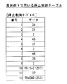
図2(A)に示すように、リール2L、2C、2Rの外周部には、各々を識別可能な複数種類の図柄(識別情報)が図柄番号順かつ所定の図柄配置間隔(図柄ピッチ)で、それぞれ21個ずつ描かれている。このリール2L、2C、2Rにより、複数種類の識別情報を可変表示可能な複数のリールが構成されている。
As shown in FIG. 2A, on the outer periphery of the
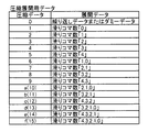
図2(B)には、各リールに描かれた図柄数が図柄の種類別に示されている。図2(B)に示された図柄のうち、特に「ダミー」は、他の図柄との組合せおよび単独のいずれの場合にも入賞を発生させないはずれ図柄である。 In FIG. 2B, the number of symbols drawn on each reel is shown for each type of symbol. Among the symbols shown in FIG. 2 (B), the “dummy” in particular is an off-line symbol that does not generate a prize in any combination with other symbols or alone.
リール2L、2C、2Rの外周部に描かれた図柄は、透視窓3において各々、上段、中段、下段の三段に表示される。透視窓3により、図柄を視認可能な可変表示部が構成されており、特に、リール2L、2C、2Rのそれぞれに対応する透視窓3の領域は、それぞれ左可変表示部、中可変表示部、右可変表示部と称される。
The symbols drawn on the outer peripheries of the
各リール2L、2C、2R(左リール2L、中リール2C、右リール2R)は、各々対応して設けられたリールモータ32L、32C、32R(図4参照)によって回転する。これにより、各リール2L、2C、2Rに配列された図柄が透視窓3に連続的に変化しつつ表示される。たとえば、リール2Lが回転することによって、図2に示す図柄番号0、1、2、3…20、0、1…の順で、各図柄番号に対応する「スイカ」、「黄7」、「ベル」、「リプレイ」…「リプレイ」、「スイカ」の図柄が左可変表示部において繰り返し可変表示(変動表示)される。
The
リールモータ32L、32C、32Rが停止することでリール2L、2C、2Rの回転が停止し、透視窓3に3つの連続する図柄が表示結果として導出表示される。たとえば、中可変表示部の下段、中段、上段に図柄番号13、14、15の各図柄が位置するときにリール2Cの回転が停止したときには、中可変表示部の下段に「チェリー1」、中段に「ベル」、上段に「スイカ」がそれぞれ表示結果として導出された状態となる。
When the reel motors 32L, 32C, and 32R are stopped, the rotation of the
本実施の形態では、168ステップ(0〜167)の周期で1周するステッピングモータをリールモータ32L、32C、32Rに用いている。各リール2L、2C、2Rには、1図柄が移動するステップ数(8ステップ)毎に分割した21の領域が定められている。これら21の領域の1つを“1コマ”と称し、リールの回転に伴う図柄の移動数(変動数)を“コマ数”と称する。これら21の領域の各々には、リールに予め定めた“リール原点位置”から0〜20の図柄番号が割り当てられており、各々に、図2(A)に示される種類の図柄が配列されている。
In the present embodiment, stepping motors that make one revolution with a cycle of 168 steps (0 to 167) are used for the reel motors 32L, 32C, and 32R. Each
図2(C)には、賭数と有効ラインとの関係が示されている。本実施の形態では、図1に示すように、各リール2L、2C、2Rの中段に並んだ図柄に跨って設定された入賞ラインL1(中段ライン)、各リール2L、2C、2Rの上段に並んだ図柄に跨って設定された入賞ラインL2(上段ライン)、各リール2L、2C、2Rの下段に並んだ図柄に跨って設定された入賞ラインL3(下段ライン)、リール2Lの下段、リール2Cの中段、リール2Rの上段、すなわち右上がりに並んだ図柄に跨って設定された入賞ラインL4(右上がりライン)、リール2Lの上段、リール2Cの中段、リール2Rの下段、すなわち右下がりに並んだ図柄に跨って設定された入賞ラインL5(右下がりライン)の5種類が入賞ラインとして定められている。
FIG. 2C shows the relationship between the number of bets and the active line. In the present embodiment, as shown in FIG. 1, a winning line L1 (middle line) set across the symbols arranged in the middle stage of each
図3は、オッズ表を示す図である。入賞役は、入賞の発生により特別遊技に移行する特別役と、特別遊技への移行がなくメダルの払出しがある小役と、新たな投資を必要とすることなく再ゲームが可能とされる再遊技役とに大別される。また、小役と再遊技役とを併せて一般役とも称する。 FIG. 3 is a diagram showing an odds table. The winning combination includes a special role that shifts to a special game when a winning occurs, a small role that does not shift to a special game and has a medal payout, and a re-game that can be replayed without requiring new investment. It is broadly divided into gamers. The small combination and the replay combination are also referred to as a general combination.
特別役には、ビッグボーナス(以下、BBとも称する。)とレギュラーボーナス(以下、RBとも称する)とがある。さらに、ビッグボーナスには、ビッグボーナス1(以下、BB1とも称する)と、ビッグボーナス(以下、BB2とも称する)と、ビッグボーナス3(以下、BB3とも称する)とがある。 The special combination includes a big bonus (hereinafter also referred to as BB) and a regular bonus (hereinafter also referred to as RB). Further, the big bonus includes a big bonus 1 (hereinafter also referred to as BB1), a big bonus (hereinafter also referred to as BB2), and a big bonus 3 (hereinafter also referred to as BB3).
小役には、チェリー、ベル、スイカがある。再遊技役には、リプレイと特殊リプレイとがある。 Small roles include cherry, bell and watermelon. There are replays and special replays in the replaying role.
各役の入賞が発生するためには、内部抽選に当選し、当該入賞役に対応する当選フラグがRAM41cに設定されている必要がある。スロットマシン1においては、これらの入賞役別に内部抽選が行なわれ、またこれらの入賞役別に当選フラグが設定される。
In order to win each winning combination, it is necessary to win the internal lottery and to set a winning flag corresponding to the winning combination in the
BB1に対応する入賞ラインの図柄の組合せは、「赤7−赤7−赤7」である。BB2に対応する入賞ラインの図柄の組合せは、「青7−青7−青7」である。BB3に対応する入賞ラインの図柄の組合せは、「黄7−黄7−黄7」である。BB1〜3のうちいずれかに入賞すると、ビッグボーナスに移行する。
The combination of the winning line symbols corresponding to BB1 is “red 7-red 7-
RBに対応する入賞ラインの図柄の組合せは、「左−中−右」のリールにおいて、「黄7−黄7−青7」である。RBに入賞すると、レギュラーボーナスに移行する。 The winning combination corresponding to the RB is “yellow 7-yellow 7-blue 7” in the “left-middle-right” reel. If you win RB, you will move to regular bonus.
図3(B)に示すように、赤7によるBB1と青7によるBB2と黄7によるBB3とは、第一種BBとも称され、これによる入賞が発生してビッグボーナスに移行すると、ビッグボーナス中のゲームにおいてRB作動図柄が揃わなくてもRB作動(JACIN)する。 As shown in FIG. 3 (B), BB1 by red 7, BB2 by blue 7 and BB3 by yellow 7 are also referred to as first-type BB. RB operation (JACIN) is performed even if the RB operation symbols are not prepared in the game in the middle.
赤7によるBB1と青7によるBB2とは、ビッグボーナス中の払い出し枚数が466枚以上となることでビッグボーナス終了条件が成立する。一方、黄7によるBB3は、ビッグボーナス中の払い出し枚数が286枚以上となることでビッグボーナス終了条件が成立する。 BB1 with red 7 and BB2 with blue 7 satisfy the big bonus end condition when the payout number in the big bonus is 466 or more. On the other hand, for BB3 by yellow 7, the big bonus end condition is satisfied when the number of payouts in the big bonus is 286 or more.
また、「黄7−黄7−青7」が揃うことによってレギュラーボーナスに移行した後は、12ゲームを消化するかまたは4回入賞が発生するかのいずれか早いほうの条件が成立することでレギュラーボーナスが終了する。
In addition, after the transition to the regular bonus when “Yellow 7-Yellow 7-
なお、BB1〜3の終了条件は、共通であってもよく、それぞれに異なる終了条件を設定してもよい。また、本実施の形態では、BB1〜3のいずれに入賞したときでも、移行するビッグボーナスは同じであるが、BB1〜3の種類によって、ビッグボーナスの遊技内容を異なるものとしてもよい。たとえば、BB1〜3の種類によって、賭数を異ならせたり、最大払出し枚数を異ならせたりすることが考えられる。 Note that the end conditions of BB1 to BB3 may be common, or different end conditions may be set for each. In the present embodiment, the big bonus to be transferred is the same regardless of which of BB1 to BB3 is won, but the game content of the big bonus may be different depending on the type of BB1 to BB3. For example, depending on the types of BB1 to BB3, the number of bets may be varied or the maximum payout number may be varied.
次に、小役について説明する。「チェリー」に対応する入賞ラインの図柄の組合せは、左および中リールは任意で、右リールに「チェリー2」が停止した状態である。「チェリー」による入賞が発生すると1枚の払い出しがある。ただし、2重複の場合には2枚の払い出しがある。
Next, a small role will be described. The combination of symbols on the winning line corresponding to “Cherry” is such that the left and middle reels are arbitrary and “
「ベル」に対応する入賞ラインの図柄の組合せは、「ベル−ベル−ベル」であり、これによる入賞が発生すると、非BB中は10枚、RB中は15枚の払い出しがある。 The combination of symbols on the winning line corresponding to “Bell” is “Bell-Bell-Bell”. When a winning is generated by this, there are 10 payouts during non-BB and 15 payouts during RB.
「スイカ」に対応する入賞ラインの図柄の組合せは、「スイカ−スイカ−スイカ」であり、これによる入賞が発生すると、非BB中およびRB中ともに15枚の払い出しがある。 The combination of the winning line symbols corresponding to “watermelon” is “watermelon-watermelon-watermelon”, and when a winning by this occurs, there are 15 payouts during non-BB and during RB.
次に、再遊技役について説明する。「リプレイ」に対応する入賞ラインの図柄の組合せは、「リプレイ−リプレイ−リプレイ」であり、「特殊リプレイ」に対応する入賞ラインの図柄の組合せは、「左−中−右」のリールにおいて、「チェリー1−ベル−ベル」、「バー−ベル−ベル」、および「黄7−ベル−ベル」である。リプレイおよび特殊リプレイのいずれかに入賞したときには、メダルの払い出しはないが、次のゲームを改めて賭数を設定することなく開始できる。 Next, the re-game player will be described. The winning line symbol combination corresponding to “Replay” is “Replay-Replay-Replay”, and the winning line symbol combination corresponding to “Special Replay” is “Left-Middle-Right” reel. "Cherry 1-bell-bell", "Bar-bell-bell", and "Yellow 7-bell-bell". When one of the replays and special replays is won, no medals are paid out, but the next game can be started again without setting the number of bets.
ただし、特殊リプレイについては、さらに、RT作動の特典が得られる。なお、RT作動とは、リプレイの当選確率が向上されたリプレイタイムへの移行を意味する。 However, for special replays, an RT operating privilege can be obtained. The RT operation means a shift to a replay time in which the replay winning probability is improved.
図2(C)に示すように、本実施の形態では、非RB中(レギュラーボーナス中でないゲーム)では、3BET(3枚賭け)することによって入賞ラインL1〜L5の全てが有効ラインとなる。また、RB中では、2BET(2枚賭け)することによって入賞ラインL1〜L5の全てが有効ラインとなる。 As shown in FIG. 2C, in the present embodiment, in a non-RB (game that is not in regular bonus), all of the winning lines L1 to L5 become effective lines by betting 3 (3 bets). Further, in the RB, all of the pay lines L1 to L5 become effective lines by betting 2 (2 bets).
次に、リールの停止制御について説明する。ストップスイッチ8L、8C、8Rの操作から対応するリール2L、2C、2Rの回転を停止するまでの最大停止遅延時間は、たとえば、190ms(ミリ秒)である。リール2L、2C、2Rは、1分間に80回転するため、この間に80×21(1リール当たりの図柄コマ数)=1680コマ分の図柄が変動することになる。
Next, reel stop control will be described. The maximum stop delay time from the operation of the stop switches 8L, 8C, 8R to the stop of rotation of the corresponding
それゆえ、最大停止遅延時間(190ms)では、最大で4コマの図柄を滑らせることができる。つまり、停止図柄として選択可能なのは、ストップスイッチ8L、8C、8Rが操作されたときに表示されている図柄と、そこから4コマ先までにある図柄の合計5コマ分の図柄である。 Therefore, at the maximum stop delay time (190 ms), it is possible to slide up to 4 symbols. That is, the symbols that can be selected as the stop symbols are the symbols for a total of five frames, that is, the symbols displayed when the stop switches 8L, 8C, and 8R are operated and the symbols that are four frames ahead.
たとえば、ストップスイッチ8L、8C、8Rのいずれかの操作が検出されたときに当該ストップスイッチに対応するリールの下段位置を基準ラインとした場合、基準ラインに表示されている図柄から4コマ先までの図柄をリールの下段に引き込んで(滑らせて)停止させることができる。 For example, when an operation of any one of the stop switches 8L, 8C, and 8R is detected, if the lower position of the reel corresponding to the stop switch is used as the reference line, from the symbol displayed on the reference line to four frames ahead Can be pulled down (slid) and stopped at the bottom of the reel.
本実施の形態では、可変表示装置の下段位置(下段の入賞ラインの位置)を“基準ライン”としている。また、停止操作が検出されたときに基準ラインに位置する図柄を含んで図柄停止に至るまでに送った図柄数を“滑りコマ数”と称し、停止操作が検出されたときに基準ラインにある図柄で停止させた場合の滑りコマ数は、“0”とする。さらに、引き込み可能な最大コマ数(たとえば、停止操作検出時に基準ラインにある図柄を除くと4コマ、基準ラインにある図柄を入れて5コマ)を“最大滑りコマ数”と称する。 In the present embodiment, the lower position (position of the lower winning line) of the variable display device is set as the “reference line”. In addition, the number of symbols sent to the symbol stop including the symbols located on the reference line when the stop operation is detected is referred to as “the number of sliding symbols”, and is on the reference line when the stop operation is detected. The number of sliding frames when stopped with a symbol is “0”. Furthermore, the maximum number of frames that can be pulled in (for example, 4 frames if symbols on the reference line are removed when detecting a stop operation, and 5 frames including symbols on the reference line) is referred to as “maximum number of sliding frames”.
図2に示されるように、図柄の「リプレイ」は、各リール2L、2C、2Rにおいて、必ず5図柄以内に1つ配列されている。これにより、どのようなタイミングで停止操作をしても必ず「リプレイ」の入賞役による入賞を発生させることができ、その結果、「リプレイ」が内部当選している場合の当該役に対応する図柄の取りこぼしを防止することで単位時間あたりの遊技者の投資額を適度に抑えて射倖性が極端に高まり過ぎることを防止できる。
As shown in FIG. 2, one “replay” of symbols is always arranged within 5 symbols in each
なお、基準ラインは、可変表示装置の下段位置に限定されるものではなく、可変表示装置の上段位置としても、中段位置としてもよい。あるいは、可変表示装置の上中下三段のいずれかの位置に限定されるものではなく、可変表示装置のリールに配列された各図柄の可変表示部に対する位置を特定できる箇所であれば、いずれの箇所を基準ラインとしてもよい。 The reference line is not limited to the lower position of the variable display device, and may be the upper position or the middle position of the variable display device. Alternatively, the position is not limited to any one of the upper, middle, and lower three positions of the variable display device, as long as the position can be specified with respect to the variable display portion of each symbol arranged on the reel of the variable display device. These points may be used as a reference line.
図4は、スロットマシンの制御回路の全体構成を示すブロック図である。
スロットマシン1には、遊技制御基板40、演出制御基板90、電源基板101が設けられている。遊技制御基板40によって遊技状態が制御され、演出制御基板90によって遊技状態に応じた演出が制御され、電源基板101によってスロットマシン1を構成する電気部品の駆動電源が生成されて各部に供給される。
FIG. 4 is a block diagram showing the overall configuration of the control circuit of the slot machine.
The
遊技制御基板40には、1枚BETスイッチ5、MAXBETスイッチ6、スタートスイッチ7、ストップスイッチ8L、8C、8R、精算スイッチ10、所定のキー操作により打止状態等を解除するためのリセット操作を検出するリセットスイッチ23、投入メダルセンサ31、リール2L、2C、2Rそれぞれに設けられたリール原点位置を検出するリールセンサ33L、33C、33Rが接続されている。
The
また、遊技制御基板40には、クレジット表示器11、遊技補助表示器12、ペイアウト表示器13、1〜3BETLED14〜16、投入要求LED17、スタート有効LED18、ウェイト中LED19、リプレイ中LED20、BETスイッチ有効LED21、左、中、右停止有効LED22L、22C、22R、メダル投入部4から投入されたメダルの流路を筐体1a内部に設けられた後述のホッパータンク側またはメダル払出口9側のいずれか一方に選択的に切り替えるための流路切替ソレノイド30、リールモータ32L、32C、32Rが接続されており、これら電気部品は、遊技制御基板40に搭載された後述のメイン制御部41の制御に基づいて駆動される。
In addition, the
遊技制御基板40には、メインCPU41a、ROM41b、RAM41c、I/Oポート41dを備えたマイクロコンピュータからなり、遊技の制御を行なうメイン制御部41、所定範囲(本実施の形態では0〜65535)の乱数を発生させる乱数発生回路42、乱数発生回路から乱数を取得するサンプリング回路43、遊技制御基板40に直接または電源基板101を介して接続されたスイッチ類から入力された検出信号を検出するスイッチ検出回路44、リールモータ32L、32C、32Rの駆動制御を行なうモータ駆動回路45、流路切替ソレノイド30の駆動制御を行なうソレノイド駆動回路46、遊技制御基板40に接続された各種表示器やLEDの駆動制御を行なうLED駆動回路47、電源投入時またはメインCPU41aからの初期化命令が入力されないときにメインCPU41aにリセット信号を与えるリセット回路48が搭載されている。ROM41bには、遊技制御用のプログラムや、リール停止制御に用いる各種のテーブルデータが格納されている。
The
乱数発生回路42は、後述するように所定数のパルスを発生する度にカウントアップして値を更新するカウンタによって構成され、サンプリング回路43は、乱数発生回路42がカウントしている数値を取得する。乱数発生回路42は、乱数の種類毎にカウントする数値の範囲が定められており、本実施の形態では、その範囲として0〜65535が定められている。メインCPU41aは、その処理に応じてサンプリング回路43に指示を送ることで、乱数発生回路42が示している数値を乱数として取得する(以下、この機能をハードウェア乱数機能という)。後述する内部抽選用の乱数は、ハードウェア乱数機能により抽出した乱数をそのまま使用するのではなく、ソフトウェアにより加工して使用する。
The random
なお、内部抽選用の乱数は、ハード回路(乱数発生回路42)のみによって生成してもよく、あるいは、ハード回路(乱数発生回路42)を用いずに、メイン制御部41が実行する遊技制御プログラム内でソフトウェア的に生成してもよい。
The random number for internal lottery may be generated only by a hardware circuit (random number generation circuit 42), or a game control program executed by the
また、メインCPU41aは、タイマ割込処理(メイン)により、特定のレジスタの数値を更新し、こうして更新された数値を乱数として取得する機能も有する(以下、この機能をソフトウェア乱数機能という)。
The
メインCPU41aは、I/Oポート41dを介して演出制御基板90に、各種のコマンドを送信する。遊技制御基板40から演出制御基板90へ送信されるコマンドは、演出中継基板80を介して一方向のみで演出制御基板90へ送られ、演出制御基板90から遊技制御基板40へ向けてコマンドが送られることはない。
The
演出制御基板90には、液晶表示器51、スピーカ52、53、リールLED54等の電気部品が接続されており、これら電気部品は、演出制御基板90に搭載されたサブ制御部91による制御に基づいて駆動される。
The
スロットマシン1においてゲームを行なう場合には、まず、メダルをメダル投入部4から投入するか、あるいはクレジット(持点)を使用して賭数を設定する。クレジットを使用するには1枚BETスイッチ5、またはMAXBETスイッチ6を操作すればよい。遊技状態に応じて定められた規定数の賭数が設定されると、入賞ラインL1〜L5(図1参照)のうち遊技状態に応じて定められた入賞ラインが有効となり、スタートスイッチ7の操作が有効な状態、すなわち、ゲームが開始可能な状態となる。遊技状態に対応する規定数を超えてメダルが投入された場合には、その分はクレジットに加算される。
When a game is played in the
ゲームが開始可能な状態でスタートスイッチ7を操作すると、メイン制御部41によってスタート操作が検出される。スタート操作の検出に基づいて、メイン制御部41は各リール2L、2C、2Rを一斉に回転開始させる。これにより、各リール2L、2C、2Rの図柄が連続的に変動する。この状態でいずれかのストップスイッチ8L、8C、8Rを操作すると、対応するリール2L、2C、2Rの回転が停止し、停止したリールの図柄の表示結果が透視窓3に導出される。以下、ストップスイッチ8L、8C、8Rのいずれかを用いてリールを停止させる操作を“停止操作”と称する。
When the
全てのリール2L、2C、2Rの回転が停止して各リールの図柄の表示結果が導出されることで1ゲームが終了する。なお、本実施の形態では、各リールの図柄の表示結果が導出されたときには、対応するリールが完全に停止する。しかしながら、これに変えて、リールの回転が停止して図柄の表示結果が導出されたときでも、リールが上下方向に振動するように動くようにしてもよい。その場合、全リールの回転が停止して全リールの図柄の表示結果が導出されたときには、各リールの振動動作を停止させてもよく、あるいは、各リールの振動動作を継続させてもよい。
The rotation of all the
全リールの図柄の表示結果が導出されたときに、有効化されているいずれかの入賞ラインL1〜L5上に予め定められた図柄の組合せが各リール2L、2C、2Rの表示結果として停止した場合には入賞が発生する。入賞が発生すると、その入賞に応じて定められた大きさの遊技価値が遊技者に付与される(規定枚数のメダルの払出し、あるいはこれに対応する数のクレジット加算)。
When the display results of the symbols for all reels are derived, the combination of symbols predetermined on any of the activated pay lines L1 to L5 is stopped as the display result of each
なお、有効化された複数の入賞ライン上にメダルの払出を伴う図柄の組合せが揃った場合には、有効化された入賞ラインに揃った図柄の組合せそれぞれに対して定められた払出枚数を合計し、合計した枚数のメダルが遊技者に対して付与される。 If a combination of symbols with payout of medals is arranged on a plurality of activated pay lines, the total number of payouts determined for each combination of symbols arranged on the activated pay line is totaled. The total number of medals is awarded to the player.
ただし、1ゲームで付与されるメダルあるいはクレジットの付与数には、上限(本実施の形態では、15)が定められており、合計数が上限を超える場合には、上限数のクレジットまたはメダルが遊技者に付与される。 However, an upper limit (15 in the present embodiment) is set for the number of medals or credits awarded in one game, and when the total number exceeds the upper limit, the upper limit number of credits or medals is It is given to the player.
図5は、リールの停止制御の概念図である。本実施の形態では、ストップスイッチ8L、8C、8Rのうち、回転中のリールに対応する停止操作が検出されると、停止操作を検出した時点のリール原点位置からのステップ数に基づいて、基準ライン(可変表示装置の下段)に位置する図柄の配列位置を特定する。 FIG. 5 is a conceptual diagram of reel stop control. In the present embodiment, when a stop operation corresponding to a rotating reel is detected among the stop switches 8L, 8C, and 8R, a reference is made based on the number of steps from the reel origin position when the stop operation is detected. The arrangement position of the symbols located on the line (lower stage of the variable display device) is specified.
次に、特定した配列位置と、各リール別に用意された停止テーブルとを用いて、停止操作が検出されたリールを停止制御する。停止テーブルは、データが動的に変化するテーブルであり、滑りコマ数または優先値のいずれか一方が図柄の配列位置別に格納される。 Next, the reels in which the stop operation is detected are controlled to stop using the specified arrangement position and the stop table prepared for each reel. The stop table is a table in which data dynamically changes, and either the number of sliding symbols or the priority value is stored for each symbol arrangement position.
以下では、1ゲーム開始後、3つのリールのうちの1つ目のリールを停止させるための停止操作を“第一停止操作”、2つ目のリールを停止させるための停止操作を“第二停止操作”、3つ目のリールを停止させるための操作を“第三停止操作”と称する。 In the following, after the start of one game, a stop operation for stopping the first reel of the three reels is referred to as “first stop operation”, and a stop operation for stopping the second reel is referred to as “second stop”. The operation for stopping the third reel is referred to as a “third stop operation”.
また、第一停止操作で停止するリールを“第一停止リール”、第二停止操作で停止するリールを“第二停止リール”、第三停止操作で停止するリールを“第三停止リール”と称する。 Also, the reel that stops by the first stop operation is called “first stop reel”, the reel that stops by the second stop operation is “second stop reel”, and the reel that stops by the third stop operation is called “third stop reel”. Called.
メイン制御部41は、停止テーブルに滑りコマ数が格納されている場合には、その滑りコマ数に基づいてリールを停止させる。停止テーブルに滑りコマ数を格納した上で、その滑りコマ数に基づいてリールを停止させる制御を“テーブル制御”と称する。
When the number of sliding symbols is stored in the stop table, the
一方、メイン制御部41は、停止テーブルに優先値が格納されている場合には、その優先値に基づいてリールを停止させる。停止テーブルに優先値を設定した上で、その優先値に基づいてリールを停止させる制御を“コントロール制御”と称する。
On the other hand, when a priority value is stored in the stop table, the
停止テーブルは、停止制御テーブルに基づいて作成される。メイン制御部41は、当選状況に応じて分けられた複数種類の停止制御テーブルを記憶している。図5に示すように、停止制御テーブルは、停止テーブルに滑りコマ数を格納するためのテーブル制御データと、停止テーブルに優先値を格納するためのコントロール制御データとを含む。ただし、テーブル制御データを含まない停止制御テーブルも存在する。
The stop table is created based on the stop control table. The
メイン制御部41は、1ゲームを開始する毎に、当選状況に応じた停止制御テーブルを選択する。そして、選択した停止制御テーブルに従って処理を進めることにより、停止制御テーブル内のテーブル制御データまたはコントロール制御データのいずれか一方に基づいて停止テーブルを作成する。
The
テーブル制御データに基づいて停止テーブルの作成を試みる処理モードを“滑りコマ数処理モード”という。これに対して、コントロール制御データに基づいて停止テーブルの作成を試みる処理モードを“優先度処理モード”という。 A processing mode that attempts to create a stop table based on the table control data is referred to as a “sliding frame number processing mode”. In contrast, a processing mode that attempts to create a stop table based on control control data is referred to as a “priority processing mode”.
“滑りコマ数処理モード”による処理の結果、停止テーブルを作成する条件が成立していると判断された場合、停止テーブルには、滑りコマ数が図柄の配列位置別に格納される。一方、“優先度処理モード”による処理の結果、停止テーブルを作成する条件が成立していると判断された場合、停止テーブルには、優先値が図柄の配列位置別に格納される。なお、停止テーブルには、滑りコマ数と優先値との双方が併せて格納されることはない。 As a result of the processing in the “sliding frame number processing mode”, when it is determined that a condition for creating a stop table is satisfied, the number of sliding frames is stored in the stop table for each symbol arrangement position. On the other hand, if it is determined as a result of processing in the “priority processing mode” that the condition for creating the stop table is satisfied, the priority value is stored in the stop table for each symbol arrangement position. In the stop table, both the number of sliding frames and the priority value are not stored together.
メイン制御部41は、作成した停止テーブルに基づいて第一停止リールを停止させた後、既に選択済みの停止制御テーブルを再度用いて停止テーブル作成処理を行ない、第二停止操作検出前に停止テーブルの値を更新することによって停止テーブルを作成し直す。
The
さらに、メイン制御部41は、作成した停止テーブルに基づいて第二停止リールを停止させた後、再び、選択済みの停止制御テーブルを用いて停止テーブル作成処理を行ない、第三停止操作検出前に停止テーブルの値を更新することによって停止テーブルを作成し直す。
Further, after stopping the second stop reel based on the created stop table, the
停止制御テーブル内のデータは、基本的にはテーブル制御データの次にコントロール制御データが実行されるように記述されている。メイン制御部41は、テーブル制御データを先に実行し、現在のリールの停止状況とテーブル制御データとが停止テーブルの作成条件を満たすときには、テーブル制御データのみに基づいて停止テーブルを作成する。この場合、コントロール制御データを参照することなく、停止制御テーブルに基づく処理を終える。
The data in the stop control table is basically described so that the control control data is executed next to the table control data. The
一方、現在のリールの停止状況とテーブル制御データとが停止テーブルの作成条件を満たさないときには、メイン制御部41は、引き続いてコントロール制御データを参照する。そして、現在のリールの停止状況とコントロール制御データとが停止テーブルの作成条件を満たすときには、コントロール制御データのみに基づいて停止テーブルを作成する。
On the other hand, when the current reel stop status and the table control data do not satisfy the stop table creation condition, the
図5に示されるように、メイン制御部41は、停止制御テーブルを参照する際に併せて参照するデータとして、滑りコマ数テーブルとビットデータ(停止テーブル作成用ビットデータ)とビットデータ組合せテーブルとをさらに記憶している。
As shown in FIG. 5, the
滑りコマ数テーブルは、リールの21コマの配列位置(停止位置)の各々に対応する滑りコマ数を予め規定したテーブルであり、0番〜145番の番号によって識別される146種類が用意されている。
The sliding frame number table is a table in which the number of sliding frames corresponding to each of the 21 frame arrangement positions (stop positions) of the reels is defined in advance, and 146 types identified by
ビットデータは、リールの21コマの配列位置の各々に対して、0または1が予め設定されたデータであり、0番〜112番の番号によって識別される113種類が用意されている。
Bit data is data in which 0 or 1 is set in advance for each of the arrangement positions of 21 frames on the reel, and 113 types identified by
ビットデータ組合せテーブルは、ビットデータの番号を、左、中、右の各々に対応して「(左用ビットデータ番号,中用ビットデータ番号,右用ビットデータ番号)」のように3つ格納したテーブルであり、0番〜77番の番号によって識別される78種類が用意されている。
The bit data combination table stores three bit data numbers such as “(left bit data number, middle bit data number, right bit data number)” corresponding to each of left, middle, and right. There are 78 types of tables identified by
これら、滑りコマ数テーブル、ビットデータ、およびビットデータ組合せテーブルの3種類のデータは、停止テーブルのようにデータが動的に変化することはなく、固定値である。 These three types of data, the sliding frame number table, the bit data, and the bit data combination table, are fixed values without dynamically changing data unlike the stop table.
メイン制御部41は、テーブル制御データに基づいた処理を実行する際には、滑りコマ数テーブルとビットデータとを参照して、停止テーブルの作成条件が成立しているか否か判断し、成立している場合にはさらに停止テーブルに滑りコマ数を設定する。
When executing the process based on the table control data, the
一方、メイン制御部41は、コントロール制御データに基づいた処理を実行する際には、ビットデータ組合せテーブルとビットデータとを参照して、停止テーブルの作成条件が成立しているか否か判断し、成立している場合にはさらに停止テーブルに優先値を設定する。
On the other hand, when executing the process based on the control control data, the
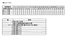
図6は、停止テーブルを示す図である。停止テーブルは、リールを停止させるときに参照されるテーブルである。停止テーブルは、25バイトのデータで構成されている。このうちの前の21バイトが配列位置順に対応するデータであり、その後は先頭4バイトのデータのコピーである。この4バイトの追加データは、リールを停止すべき位置を停止テーブルから検索する処理を高速化するためのデータである。この4バイトの追加データを設けておくことによって、停止操作時に計算される停止可能範囲の先頭位置が21コマのうちのどの位置であっても、そこから5コマ分の連続したデータを連続した5バイトから取得できるようにしている。 FIG. 6 shows a stop table. The stop table is a table that is referred to when the reel is stopped. The stop table is composed of 25 bytes of data. The preceding 21 bytes are the data corresponding to the order of the array position, and the subsequent 4 bytes are a copy of the data. The 4-byte additional data is data for speeding up the process of searching the stop table for the position where the reel should be stopped. By providing this 4 bytes of additional data, continuous data for 5 frames from the top of the 21 frames that can be calculated at the time of the stop operation is continuous. It can be obtained from 5 bytes.
なお、停止テーブルに4バイトの追加データを設けなくてもよい。つまり、停止テーブルを21バイトのデータで構成してもよい。 It is not necessary to provide 4-byte additional data in the stop table. That is, the stop table may be composed of 21 bytes of data.
図6には、停止テーブルに格納される値の意味が示されている。「0」〜「14」はコントロール制御において用いられる優先値であって、「0」は停止禁止位置を示し、「1」は最低の優先値を示し、「2」〜「14」は値が大きいほど停止位置として優先することを示す。 FIG. 6 shows the meaning of the values stored in the stop table. “0” to “14” are priority values used in the control control, “0” indicates the stop prohibition position, “1” indicates the lowest priority value, and “2” to “14” indicate values. A larger value indicates that priority is given to the stop position.
「16」〜「20」はテーブル制御において用いられる滑りコマ数であって、「16」は滑りコマ数0、「17」は滑りコマ数1、「18」は滑りコマ数2、「19」は滑りコマ数3、「20」は滑りコマ数4を意味する。
“16” to “20” are the number of sliding frames used in the table control. “16” is the number of sliding
なお、作成済みの停止テーブルにおいて、16以上のデータと16未満のデータとが混在することはない。つまり、作成済みの停止テーブルには、滑りコマ数および優先値のうちのいずれか一方が格納されている。 In the generated stop table, 16 or more data and less than 16 data are not mixed. In other words, the prepared stop table stores either the number of sliding symbols or the priority value.
図7は、停止制御テーブルの種類を説明するための図である。停止制御テーブルとして、内部当選状況に応じた30種類のデータが規定されている。たとえば、図7に示すように、特別役の当選フラグが設定されておらず、かつそれ以外の入賞役についての当選フラグも設定されていない外れのゲームには、停止制御テーブル1が対応する。あるいは、BB1(赤7)の当選フラグが設定されており、かつ、チェリーの当選フラグが設定されているゲームには、停止制御テーブル8が対応する。 FIG. 7 is a diagram for explaining types of the stop control table. As the stop control table, 30 types of data corresponding to the internal winning situation are defined. For example, as shown in FIG. 7, the stop control table 1 corresponds to an out-of-game in which the winning flag for the special combination is not set and the winning flag for the other winning combinations is not set. Alternatively, the stop control table 8 corresponds to a game in which the winning flag of BB1 (red 7) is set and the winning flag of cherry is set.
図8は、停止制御テーブルの構成を説明するための概略図である。停止制御テーブルは、ア〜オのテーブル制御データと、カのコントロール制御データと、キのTBLENDとに大別される。 FIG. 8 is a schematic diagram for explaining the configuration of the stop control table. The stop control table is roughly divided into (a) to (e) table control data, (f) control control data, and (ii) TBLEND.
テーブル制御データは、テーブル制御用の停止テーブルを作成するために用いられる。コントロール制御データは、コントロール制御用の停止テーブルを作成するために用いられる。TBLENDは、停止制御テーブルの終了を示すエンドデータである。 The table control data is used to create a stop table for table control. The control control data is used to create a stop table for control control. TBLEND is end data indicating the end of the stop control table.
テーブル制御データの先頭には、3バイトの滑りコマ数データAと、3n(n=1,2,…)バイトの滑りコマ数データBとが順に配置されている。さらに、滑りコマ数処理モード1を示す設定データTBLMD1(値250)に続いて、3n(n=1,2,…)バイトの滑りコマ数制御データ1が配置され、その後に滑りコマ数処理モード2を示す設定データTBLMD2(値252)に続いて、3n(n=1,2,…)バイトの滑りコマ数制御データ2が配置され、その後に滑りコマ数処理モード3を示す設定データTBLMD2(値254)に続いて、3n(n=1,2,…)バイトの滑りコマ数制御データ3が配置されている。
At the head of the table control data, 3 bytes of sliding frame number data A and 3n (n = 1, 2,...) Bytes of sliding frame number data B are sequentially arranged. Further, the setting data TBLMD1 (value 250) indicating the sliding frame
コントロール制御データは、1バイトの「PRIO+a」に続いて、nバイトの設定箇所特定用データが配置されることにより、構成されている。「PRIO+a」は235〜249の値をとる。図に示すように、「PRIO」が235の固定値で、「a」が優先値を示す0〜14の値をとる。停止制御テーブルの種類によっては、カのコントロール制御データが連続して複数配置されているものが存在する。 The control control data is configured by arranging 1-byte “PRIO + a” followed by n-byte setting location specifying data. “PRIO + a” takes a value of 235 to 249. As shown in the figure, “PRIO” is a fixed value of 235, and “a” takes a value of 0 to 14 indicating a priority value. Depending on the type of the stop control table, there is a table in which a plurality of control control data is continuously arranged.
なお、停止制御テーブルの中には、ア〜オのテーブル制御データが存在しない種類のものがある。ただし、いずれの停止制御テーブルも、コントロール制御データとTBLENDとを含んでいる。 Note that some stop control tables do not have the table control data A to E. However, each stop control table includes control control data and TBLEND.
図9は、停止制御テーブルの詳細を説明するための図である。図9を参照して、テーブル制御データである滑りコマ数制御データ(A、B、1〜3)は、滑りコマ数テーブルを選択するために用いられる。 FIG. 9 is a diagram for explaining details of the stop control table. Referring to FIG. 9, sliding frame number control data (A, B, 1 to 3), which is table control data, is used to select a sliding frame number table.
また、滑りコマ数制御データ1〜3の前に配置された処理モード1〜3の設定データは、メイン制御部41が各滑りコマ数制御データを実行する前に読み込んで、停止制御の処理モードを対応する滑りコマ数処理モード1〜3のいずれかに切換えるための設定データである。
The setting data of the
滑りコマ数制御データAは、全リールが未停止のとき、すなわち、第一停止に使用される。したがって、1つでもリールが停止しているときには、滑りコマ数制御データAが参照されても停止テーブルの作成条件が成立していないと判断され、の次のデータが参照される。 The sliding frame number control data A is used when all reels are not stopped, that is, for the first stop. Therefore, when at least one reel is stopped, it is determined that the stop table creation condition is not satisfied even if the sliding frame number control data A is referred to, and the next data is referred to.
滑りコマ数制御データBは、順押しの第二停止および第三停止と、挟み押しの第二停止および第三停止とに使用される。順押しとは、リールの停止順が左、中、右であることを意味する。また、挟み押しとは、リールの停止順が左、右、中であることを意味する。 The sliding frame number control data B is used for the second stop and the third stop of the forward press and the second stop and the third stop of the pinch press. The forward push means that the reel stop order is left, middle, and right. In addition, the pinching push means that the stop order of the reels is left, right, and middle.
滑りコマ数制御データ1は、順押しの第二停止と、挟み押しの第二停止とに使用される。滑りコマ数制御データ2は、順押しの第三停止に使用される。滑りコマ数制御データ3は、挟み押しの第三停止に使用される。
The sliding frame
滑りコマ数制御データの中には、たとえば、滑りコマ数制御データBと滑りコマ数制御データ1のように、順押しの第二停止と挟み押しの第二停止とに共通に用いられるデータが存在する。しかし、制御上、複数の滑りコマ数制御データが併せて用いられて停止テーブルが作成されることはない。
In the sliding frame number control data, for example, the sliding frame number control data B and the sliding frame
たとえば、順押しの第二停止に対応する停止テーブルを作成する際には、まず、停止制御テーブルにおいて、滑りコマ数制御データ1よりも先に配置された滑りコマ数制御データBが用いられて停止テーブルを作成する諸条件が成立するかが判断され、成立する場合には、滑りコマ数制御データBに基づいて停止テーブルが作成される。この場合、滑りコマ数制御データ1以降のデータは無視される。
For example, when creating a stop table corresponding to the second stop of the forward push, first, the sliding piece number control data B arranged before the sliding piece
一方、滑りコマ数制御データBでは停止テーブルを作成する諸条件が成立しないと判断されたとき、後続の滑りコマ数制御データ1が用いられて、停止テーブルを作成する諸条件が成立するかが判断される。
On the other hand, when it is determined that the conditions for creating the stop table are not satisfied in the sliding frame number control data B, whether the conditions for creating the stop table are satisfied using the subsequent sliding frame
滑りコマ数制御データは、いずれも3バイトで一単位のデータを構成している。なお、図9では、滑りコマ数制御データ1〜3について、一単位のデータのみを示しているが、実際には図8を用いて説明したとおり、滑りコマ数制御データ1〜3は、3バイトを一単位とする複数のデータ(3n)を構成し得る。
Each of the sliding frame number control data constitutes one unit of 3 bytes. In FIG. 9, only one unit of data is shown for the sliding frame
滑りコマ数制御データAの1バイト目は、左リールに用いる滑りコマ数テーブルの番号であり、2バイト目は、中リールに用いる滑りコマ数テーブルの番号であり、3バイト目は、右リールに用いる滑りコマ数テーブルの番号である。 1 byte of the sliding frame number control data A is the number of the number of sliding symbols tables to be used for the left reel, the second byte, Ri Oh the number of the number of sliding symbols tables to be used in the middle reel, 3 byte, right This is the number of the sliding frame number table used for the reel.
滑りコマ数制御データBおよび滑りコマ数制御データ1の1バイト目は、第一停止リールの停止位置をチェックするために用いるビットデータの番号である。滑りコマ数制御データBの2バイト目および3バイト目は、中リールおよび右リールに用いる滑りコマ数テーブルの番号である。
The first byte of the sliding frame number control data B and the sliding frame
滑りコマ数制御データBは、第一停止時に第二停止および第三停止までの引き込み制御が決定できる場合(引き込み率100%の図柄組合せを決まったラインに引込む場合や、第一停止で当選図柄を表示できないことが確定した場合等)に使用する。この滑りコマ数制御データBは、第一停止リールの停止位置だけで残りの2リールの滑りコマ数テーブルを決定するためのデータである。 The sliding frame number control data B can be determined when the pull-in control until the second stop and the third stop can be determined at the first stop (when the combination of symbols with a pull-in rate of 100% is pulled into a fixed line, Is used when it is determined that cannot be displayed. The sliding frame number control data B is data for determining the sliding frame number table for the remaining two reels only at the stop position of the first stop reel.
一方、滑りコマ数制御データ1は、第一停止時に、第二停止および第三停止の引き込み制御が決定できない場合(第二停止の位置によって第三停止の滑りコマ数テーブルを変更する必要がある場合)に使用されるデータである。
On the other hand, the sliding piece
滑りコマ数制御データ2および滑りコマ数制御データ3の1バイト目は、第一停止リールの停止位置をチェックするために用いるビットデータの番号であり、2バイト目は、第二停止リールの停止位置をチェックするために用いるビットデータの番号である。
The first byte of the sliding frame
滑りコマ数制御データ2は順押しの第三停止に用いられる一方、滑りコマ数制御データ3は挟み押しの第三停止に用いられるため、2バイト目の第二停止リールは、前者では中リールを意味する一方、後者では右リールを意味する。
The sliding frame
滑りコマ数制御データ2および滑りコマ数制御データ3の3バイト目は、第三停止に用いる滑りコマ数テーブルの番号であり、滑りコマ数制御データ2の場合には右リール用として、滑りコマ数制御データ3の場合には中リール用として、それぞれ用いられる。
The third byte of the sliding frame
コントロール制御データは、優先順位設定データ「PRIO+a」と、これに続く設定箇所特定用データとから成る。コントロール制御データは、変則押しの第二停止・第三停止とに必ず使用される。変則押しとは、リールの第一停止が中となる場合、またはリールの第一停止が右となる場合を意味する。なお、コントロール制御データは、変則押しの第二停止・第三停止のみに使用されるのではなく、順押しあるいは挟み押しの第二停止においても、第一停止リールの出目に応じて使用され得る。 The control control data includes priority order setting data “PRIO + a” followed by setting location specifying data. The control data is always used for the second stop and third stop of the irregular push. The irregular push means that the first stop of the reel is in the middle or the first stop of the reel is on the right. Note that the control control data is used not only for the second stop and third stop of irregular pressing, but also for the second stop of forward pressing or pinching, depending on the outcome of the first stop reel. obtain.
設定箇所特定用データは、優先値の設定に用いるビットデータ組合せテーブルの番号を示すデータである。メイン制御部41は、設定箇所特定用データによって指定された番号のビットデータ組合せテーブルを参照して、優先順位設定データが示す優先値を設定する停止テーブルのビット位置を特定する。
The setting location specifying data is data indicating the number of the bit data combination table used for setting the priority value. The
設定箇所特定用データは、可変長のデータであって、停止制御テーブルの種類に応じて、1つあるいは複数のビットデータ組合せテーブル番号を示すデータから構成されている。 The setting location specifying data is variable-length data, and is composed of data indicating one or a plurality of bit data combination table numbers according to the type of the stop control table.
滑りコマ数制御データAおよび滑りコマ数制御データBの3バイトデータのうち、1バイト目のデータは250よりも小さい値である。これに対して、処理モード1〜3の設定データTBLMD1〜3、および「PRIO+a」のいずれも、250以上の値である。
Of the 3-byte data of the sliding frame number control data A and the sliding frame number control data B, the first byte data is a value smaller than 250. On the other hand, all of the setting data TBLMD1 to 3 of the
また、停止制御テーブルにおいて、滑りコマ数制御データBが存在する場合には、必ずその直前に滑りコマ数制御データAが配置されている。 Further, in the stop control table, when the sliding frame number control data B exists, the sliding frame number control data A is always arranged immediately before that.
これらのことより、メイン制御部41は、停止制御テーブルを参照するときに、先頭1バイト目のデータが250よりも小さい値であることに基づいて、停止制御テーブルの先頭に滑りコマ数制御データAが配置されていることを判別する。
Accordingly, when the
さらに、メイン制御部41は、先頭の3バイトデータの次の1バイト目のデータが250よりも小さい値であることに基づいて、停止制御テーブルに滑りコマ数制御データBが配置されていることを判別する。
Further, the
また、メイン制御部41は、停止制御テーブルを先頭から順に参照したときに、TBLMD1に対応する値のデータが存在すれば、それ以降の250未満のデータが滑りコマ数制御データ1であると判別する。同様に、TBLMD2に対応する値のデータが存在すれば、それ以降の250未満のデータが滑りコマ数制御データ2であると判別し、TBLMD3に対応する値のデータが存在すれば、それ以降の250未満のデータが滑りコマ数制御データ3であると判別する。
In addition, when the
また、メイン制御部41は、停止制御テーブルを先頭から順に参照したときに、「PRIO+a」に対応する値のデータが存在すれば、それ以降の「PRIO+a」に対応する値を超えないデータを設定箇所特定用データであると判別する。
Also, when the
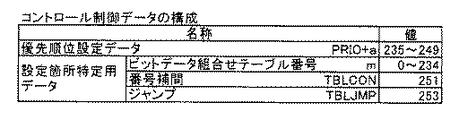
図10は、停止制御テーブルに含まれるコントロール制御データの構成を説明するための図である。図示のとおり、優先順位設定データ「PRIO+a」は、235〜249のデータである。一方、これに続く設定箇所特定用データは、単にビットデータ組合せテーブル番号を羅列したデータの場合もあるが、図10のようなビットデータ組合せテーブル番号に番号補間データTBLCONあるいはジャンプデータTBLJMPを組合せたデータから構成される場合もある。 FIG. 10 is a diagram for explaining the configuration of control control data included in the stop control table. As illustrated, the priority setting data “PRIO + a” is data of 235 to 249. On the other hand, the setting location specifying data subsequent to this may be simply data in which bit data combination table numbers are listed, but the bit data combination table number as shown in FIG. 10 is combined with number interpolation data TBLCON or jump data TBLJMP. Sometimes it consists of data.
番号補間データTBLCONは、連続しない2つのビットデータ組合せテーブル番号の間に配置される。このように配置された番号補間データTBLCONと2つのビットデータ組合せテーブル番号との組合せデータは、TBLCONの前に位置するビットデータ組合せテーブル番号からTBLCONの後ろに位置するビットデータ組合せテーブル番号までの連続する3つ以上のビットデータ組合せテーブル番号が指定されていることを意味する。 The number interpolation data TBLCON is arranged between two non-consecutive bit data combination table numbers. The combination data of the number interpolation data TBLCON and the two bit data combination table numbers arranged in this way is continuous from the bit data combination table number located before TBLCON to the bit data combination table number located after TBLCON. This means that three or more bit data combination table numbers are designated.
たとえば、「4,TBLCON,9」は、「4,5,6,7,8,9」と同義である。
このように、番号補間データTBLCONを用いることによって、数多くのビットデータ組合せテーブル番号を記述する際にデータ量が大きくなることを防止している。
For example, “4, TBLCON, 9” is synonymous with “4, 5, 6, 7, 8, 9”.
Thus, by using the number interpolation data TBLCON, it is possible to prevent the amount of data from becoming large when describing many bit data combination table numbers.
ジャンプデータTBLJMPは、他の番地のデータへジャンプすることを意味するデータである。このデータの直後には、ジャンプ先への相対距離を示す1バイトのデータが続く(たとえば、図16の停止制御テーブル16の「d_3rb_a$−1」参照)。 The jump data TBLJMP is data that means jumping to data of another address. Immediately after this data, 1-byte data indicating the relative distance to the jump destination follows (for example, refer to “d_3rb_a $ −1” in the stop control table 16 of FIG. 16).
ジャンプデータTBLJMPは、複数の停止制御テーブルで共通しているコントロール制御データ部分について、各々の停止制御テーブル内に記述するのではなく、特定の番地に共通データを記述しておき、その番地へジャンプして共通データを共有できるようにするためのデータである。これにより、データ量の削減を図っている。 The jump data TBLJMP does not describe the control control data portion common to a plurality of stop control tables in each stop control table, but describes common data at a specific address and jumps to that address. Thus, the common data can be shared. As a result, the amount of data is reduced.
ゆえに、コントロール制御データは、実際には図10に示す優先順位設定データとビットデータ組合せテーブル番号と番号補間データとジャンプデータとを必要に応じて任意順に並べた可変長のデータである。 Therefore, the control control data is actually variable-length data in which the priority order setting data, bit data combination table number, number interpolation data, and jump data shown in FIG. 10 are arranged in any order as necessary.
コントロール制御データは、当選状況に応じて予め定めた出目を優先させて停止させ、あるいは予め定めた出目が絶対に停止しないようにコントロールするための優先度パラメータである。 Control control data is a priority parameter for giving priority to stopping a predetermined outcome according to the winning situation, or for controlling so that a predetermined outcome is never stopped.
たとえば、青7のBB2とベルとが当選しているゲームにおいては、次のような優先順位に従いリールが停止するように、コントロール制御データが作成されている。
For example, in a game where
[優先順位1]:赤7をテンパイさせること(第二停止によって、第一停止リールに停止済みの出目との関係において、対象図柄が2つ有効ラインに揃うこと)を禁止(優先値=0)。 [Priority 1]: Prohibition of tempering red 7 (with the second stop, two target symbols are aligned on the active line in relation to the outcome that has been stopped on the first stop reel) (priority value = 0).
[優先順位2]:青7を下段ラインまたは右上がりラインにテンパイさせる(優先値=7)。
[Priority 2]:
[優先順位3]:青7を有効ラインのいずれかに停止させる(優先値=6)。
[優先順位4]:ベルを中段ラインに停止させる(優先値=5)。
[Priority 3]:
[Priority 4]: The bell is stopped at the middle line (priority value = 5).
[優先順位5]:ベルを上段ラインまたは右上がりラインに停止させる(優先値=4)。 [Priority 5]: The bell is stopped at the upper line or the right-up line (priority value = 4).
[優先順位6]:ベルを下段ラインまたは右下がりラインに停止させる(優先値=3)。 [Priority 6]: Stop the bell on the lower line or the lower right line (priority value = 3).
[優先順位7]:はずれの出目にする(優先値=2)。
図11は、ビットデータ組合せテーブルの具体例を説明するための図である。ビットデータ組合せテーブルは、ビットデータの番号を、(左、中、右)の各々のリールに対応して3つ指定するデータから成るテーブルである。
[Priority 7]: Make a mistake (priority value = 2).
FIG. 11 is a diagram for explaining a specific example of the bit data combination table. The bit data combination table is a table composed of data designating three bit data numbers corresponding to the respective reels (left, middle and right).
たとえば、番号3のビットデータ組合せテーブル(4,3,7)は、左リールに対応して番号4のビットデータを指定し、中リールに対応して番号3のビットデータを指定し、右リールに対応して番号7のビットデータを指定している。ビットデータ組合せテーブルは、コントロール制御データに基づいて停止テーブルの作成を試みる“優先度処理モード”でのみ使用される。
For example, in the bit data combination table (4, 3, 7) of
図12は、停止制御テーブルの具体例を示す図である。たとえば、番号1の停止制御テーブルは、先頭バイトが「0」であって、設定データTBLMD1の値「250」よりも小さい。このため、「0」を含む(0,1,2)は、メイン制御部41によって滑りコマ数制御データAと判断される。続く「70」も「250」より小さいため、「70」を含む(70,3,4)は、滑りコマ数制御データBと判断される。以下、PRIO+2の直前まで「250」より小さい値が続くため、すべて滑りコマ数制御データBと判断される。その結果、最終の滑りコマ数制御データBは、(18,14,4)であると判断される。
FIG. 12 is a diagram illustrating a specific example of the stop control table. For example, in the stop control table of
続くデータは、優先値を「2」とする「PRIO+2」であるため、ここからがコントロール制御データであると判断される。さらに、続く「59」は、59番のビットデータ組合せテーブルを指定するデータであると判断される。続くデータとして「TBLEND」が配置されているため、メイン制御部41は、これにより停止制御テーブルの処理を終える。
Since the subsequent data is “PRIO + 2” with the priority value “2”, it is determined that this is the control control data. Further, the following “59” is determined to be data specifying the 59th bit data combination table. Since “TBLEND” is arranged as subsequent data, the
なお、図12においては、代表例として、番号1,6,16の停止制御テーブルを示し、その他の停止制御テーブルについては記載を省略している。
In FIG. 12, stop control tables with
図13は、滑りコマ数テーブルの具体例を示す図である。滑りコマ数テーブルは、1リール分(21コマ分)の滑りコマ数を圧縮した可変長データである。滑りコマ数テーブルは、番号0〜145の146種類が規定されており、左、中、右リールに対して共用される。このため、左、中、右リール別に滑りコマ数テーブルを設ける場合と比較して、データ容量を削減できる。
FIG. 13 is a diagram showing a specific example of the sliding frame number table. The sliding frame number table is variable-length data obtained by compressing the number of sliding frames for one reel (21 frames). The sliding frame number table defines 146 types of
滑りコマ数テーブルのデータは圧縮されており、先頭1バイト目の下位4ビットはデータ長(滑りコマ数のデータのバイト数)を示している。たとえば、番号0の滑りコマ数テーブルの1バイト目の「65」のうち、下位4ビットの「5」が、データ長を示す。したがって、1バイト目の上位4ビットと2バイト目以降のデータによって滑りコマ数データが特定される。
The data of the sliding frame number table is compressed, and the lower 4 bits of the first byte indicate the data length (the number of bytes of data of the sliding frame number). For example, among the “65” in the first byte of the
図14は、圧縮展開用データを示す図である。この圧縮展開用データは、メイン制御部41が滑りコマ数テーブルの圧縮データを展開するために用いられる。図に示すように、たとえば、滑りコマ数テーブルに規定された圧縮データ「1」は、滑りコマ数「0」に展開され、滑りコマ数テーブルに規定された圧縮データ「2」は、滑りコマ数「1」に展開される。あるいは、滑りコマ数テーブルに規定された圧縮データ「6」は、滑りコマ数「1,0」に展開され、滑りコマ数テーブルに規定された圧縮データ「d」は、滑りコマ数「3,2,1,0」に展開される。
FIG. 14 is a diagram showing compression / decompression data. This compression / decompression data is used by the
圧縮データ「0」は、同じパターンの繰り返しがあるときの繰り返し回数を示すために用いられるデータである。繰り返し回数は、「0」と、繰り返し対象の圧縮データX(X=1〜15)とを2進数形式に並べることで示す。 The compressed data “0” is data used to indicate the number of repetitions when the same pattern is repeated. The number of repetitions is indicated by arranging “0” and the compression data X (X = 1 to 15) to be repeated in a binary format.
たとえば、繰り返すデータをX(X=1〜15)とすると、「X0」は、「21+0=2」という数式の適用により、「X」を2つ並べた「XX」に展開される。「XX」は、「21+1=3」という数式の適用により「X」を3つ並べた「XX」に展開される。 For example, if the data to be repeated is X (X = 1 to 15), “X0” is expanded to “XX” in which two “X” s are arranged by applying the mathematical expression “2 1 + 0 = 2”. “XX” is expanded into “XX” in which three “X” s are arranged by applying the mathematical expression “2 1 + 1 = 3”.
同様に、「X00」は、「22+0+0=4」という数式の適用により「XXXX」に展開され、「X0X」は、「22+0+1=5」という数式の適用により「XXXXX」に展開され、「XX0」は、「22+21+0=6」という数式の適用により「XXXXX」に展開され、「XXX」は、「22+21+1=7」という数式の適用により「XXXXXXX」に展開され、「X000」は、「23+0+0+0=8」という数式の適用により「XXXXXXXX」に展開される。 Similarly, “X00” is expanded to “XXXX” by applying the formula “2 2 + 0 + 0 = 4”, and “X0X” is expanded to “XXXX” by applying the formula “2 2 + 0 + 1 = 5”. , “XX0” is expanded to “XXXX” by applying the formula “2 2 +2 1 + 0 = 6”, and “XXX” is changed to “XXXXXXX” by applying the formula “2 2 +2 1 + 1 = 7”. “X000” is expanded to “XXXXXXX” by applying the mathematical expression “2 3 + 0 + 0 + 0 = 8”.
ただし、圧縮データの先頭にある「0」は、単なるダミーデータであり、データ展開時には無視される。 However, “0” at the head of the compressed data is simply dummy data and is ignored during data expansion.
メイン制御部41は、図13に示す滑りコマ数テーブルの中から滑りコマ数テーブルを選択したときに、圧縮展開用データを用いて圧縮データを展開し、21コマの各々に対応する滑りコマ数を羅列した滑りコマ数データを得る。
When the
図15は、ビットデータ(停止テーブル作成用ビットデータ)の具体例を示す図である。ビットデータは、図示のように、図柄位置記号A〜U(図柄番号0〜21)の各々に対して、0または1が予め設定されたデータである。ビットデータは、番号0〜112の113種類が用意されているが、リール別に規定されておらず、複数のリールに共用されている。このため、リール別にビットデータを設ける場合と比較して、データ容量を削減できる。
FIG. 15 is a diagram showing a specific example of bit data (stop table creation bit data). As shown in the figure, the bit data is data in which 0 or 1 is set in advance for each of the symbol position symbols A to U (
ビットデータは、想定される表示結果をリールにおける図柄の配列位置別に示しており、「1」が格納されている箇所は、その位置でリールが停止することが想定されている箇所を、「0」が格納されている箇所は、その位置でリールが停止することが想定されていない箇所を、それぞれ示す。 The bit data indicates the expected display result for each symbol arrangement position on the reel. A location where “1” is stored indicates a location where the reel is supposed to stop at that location. "Is stored in each position where the reel is not supposed to stop at that position.
ビットデータは、停止テーブルを作成する際の滑りコマ数処理モードと優先度処理モードとの双方に共用される。このため、処理モード別にビットデータを設ける場合と比較して、データ容量を削減できる。 Bit data is shared by both the sliding frame number processing mode and the priority processing mode when creating the stop table. Therefore, the data capacity can be reduced compared to the case where bit data is provided for each processing mode.
ビットデータは、滑りコマ数処理モードにおいては、いずれの滑りコマ数制御データに基づいて滑りコマ数テーブルを選択するのかを決定するために用いられる。一方、ビットデータは、優先度処理モードにおいては、停止テーブル内で優先値を設定する箇所および設定する優先値の大きさを決定するために用いられる。 In the sliding frame number processing mode, the bit data is used to determine which sliding frame number control data is selected based on which sliding frame number control data. On the other hand, in the priority processing mode, the bit data is used to determine the location where the priority value is set in the stop table and the size of the priority value to be set.
次に、図16〜図21を参照して、メイン制御部41が実行する停止制御の手順を説明する。図16は、停止制御処理を説明するためのフローチャートである。
Next, stop control procedures executed by the
まず、スタートスイッチ7が操作されることに基づいて、スタート操作が検出される(S1)。次に、内部抽選処理が実行される(S2)。また、スタート操作の検出に基づいて、リール2L、2C、2Rの変動(回転)が開始される。
First, a start operation is detected based on the operation of the start switch 7 (S1). Next, an internal lottery process is executed (S2). Further, the fluctuation (rotation) of the
S2の内部抽選処理について詳細に説明する。内部抽選とは、入賞の発生(入賞表示結果の導出)を許容するか否かを、可変表示装置2の表示結果が導出表示される以前に(実際には、スタートスイッチ7の操作検出時に)決定することである。
The internal lottery process in S2 will be described in detail. In the internal lottery, whether or not winning is permitted (derivation of the winning display result) is determined before the display result of the
内部抽選では、まず、乱数発生回路42から内部抽選用の乱数(0〜65535の整数)が取得される。次に、遊技状態に応じて定められた抽選対象役の組合せについて、取得した内部抽選用の乱数と、遊技状態、賭数および設定値に応じて定められた各役および役の組合せの当選値とが判定される。
In the internal lottery, first, a random number for internal lottery (an integer from 0 to 65535) is acquired from the random
判定の結果、当選ありとなったときには、当選した役に対応する当選フラグが設定される。この当選フラグは、1ゲームが終了する毎に消去される。ただし、ビッグボーナス当選フラグについては、ビッグボーナス入賞が発生するまで、次回のゲームに持ち越される。RAM41cにより、当選フラグを記憶する当選フラグ記憶手段が構成されている。
If the result of the determination is that there is a winning combination, a winning flag corresponding to the winning combination is set. The winning flag is deleted every time one game is finished. However, the big bonus winning flag is carried over to the next game until a big bonus winning is generated. The
本実施の形態においては、当選値の一部またはすべてが重複して設定された入賞役が存在する。このため、1ゲームにおいて複数種類の役が同時に当選することもあり得る。 In the present embodiment, there is a winning combination in which some or all of the winning values are set redundantly. For this reason, a plurality of types of winning combinations may be won simultaneously in one game.
S2の内部抽選処理の後、遊技状態(特別遊技中か一般遊技中か)、持越しフラグの有無、およびS2による当選状況が判別される(S3)。そして、S3の判別結果に対応する停止制御テーブルが選択される(S4)。 After the internal lottery process of S2, the game state (whether special game or general game), presence / absence of carryover flag, and winning status by S2 are determined (S3). Then, the stop control table corresponding to the determination result of S3 is selected (S4).
次に、停止テーブル作成処理のサブルーチンが実行される(S5)。この処理については、図17を用いて後述する。停止テーブル作成処理が終了した後に、停止操作が有効化される。具体的には、メイン制御部41は、停止テーブル作成処理が終了し、かつ、リールの回転速度が所定速度に達した段階で、停止操作の検出信号を受付可能な状態になる。
Next, a subroutine for stop table creation processing is executed (S5). This process will be described later with reference to FIG. After the stop table creation process is completed, the stop operation is validated. Specifically, the
その後、第一停止操作が検出されると(S6)、リール2L、2C、2Rのうち、第一停止操作に対応するリールの基準ラインに位置する図柄の番号が特定され、第一停止操作に対応するリールを第一停止リールとして、S5で作成された停止テーブルに基づいて停止させる処理が実行される(S7)。
Thereafter, when the first stop operation is detected (S6), the number of the symbol positioned on the reference line of the reel corresponding to the first stop operation is specified among the
たとえば、滑りコマ数により停止テーブルが作成されている場合には、以下に説明するテーブル制御によってリールを停止させる。まず、メイン制御部41は、停止テーブルを参照して、停止させるリールの基準ラインに位置する図柄の図柄番号に対応する滑りコマ数を取得する。続いて、メイン制御部41は、取得した滑りコマ数分だけリールを回転させてからリールを停止させる。
For example, when the stop table is created based on the number of sliding frames, the reel is stopped by table control described below. First, the
これに対して、優先値により停止テーブルが作成されている場合には、以下に説明するコントロール制御によってリールを停止させる。まず、メイン制御部41は、停止テーブルを参照して、停止させるリールの基準ラインに位置する図柄の優先値と、これを先頭にして連続する回転送り方向の4図柄の各々に対応する優先値を取得する。続いて、メイン制御部41は、取得した優先値のうち最も大きい値に対応する図柄番号の図柄が基準ラインに達するまでリールを回転させてからリールを停止させる。
On the other hand, when the stop table is created with the priority value, the reel is stopped by the control control described below. First, the
次に、第二停止に備えて、停止テーブル作成処理が再び実行される(S8)。
その後、第二停止操作が検出されると(S9)、リール2L、2C、2Rのうち、第二停止操作に対応するリールの基準ラインに位置する図柄の番号が特定され、第二停止操作に対応するリールを第二停止リールとして、S8で作成された停止テーブルに基づいて停止させる処理が実行される(S10)。
Next, in preparation for the second stop, stop table creation processing is executed again (S8).
Thereafter, when the second stop operation is detected (S9), the symbol number located on the reference line of the reel corresponding to the second stop operation is specified among the
第二停止リールを停止させる処理は、第一停止の際のS7の処理と同様であり、停止テーブルに基づいて、テーブル制御またはコントロール制御によって第二停止リールが停止する。 The process of stopping the second stop reel is the same as the process of S7 at the first stop, and the second stop reel is stopped by table control or control control based on the stop table.
次に、第三停止に備えて、停止テーブル作成処理が再び実行される(S11)。その後、第三停止操作が検出されると(S12)、リール2L、2C、2Rのうち、第三停止操作に対応するリールの基準ラインに位置する図柄の番号が特定され、第三停止操作に対応するリールを第三停止リールとして、S11で作成された停止テーブルに基づいて停止させる処理が実行される(S13)。
Next, in preparation for the third stop, the stop table creation process is executed again (S11). Thereafter, when the third stop operation is detected (S12), the number of the symbol located on the reference line of the reel corresponding to the third stop operation among the
第三停止リールを停止させる処理は、第一停止の際のS7の処理と同様であり、停止テーブルに基づいて、テーブル制御またはコントロール制御によって第三停止リールが停止する。 The process of stopping the third stop reel is the same as the process of S7 at the first stop, and the third stop reel is stopped by table control or control control based on the stop table.
次に、結果判定処理により、入賞の有無および入賞がある場合にはその種類が判定される(S14)。次に、払出処理により、入賞がある場合には入賞の種類に応じたメダルが払出され、あるいはクレジットが加算される(S15)。 Next, in the result determination process, the presence / absence of a winning and the type of winning are determined (S14). Next, in the payout process, if there is a win, a medal corresponding to the type of win is paid out or a credit is added (S15).
次に、停止制御ポインタの値がクリア(1にリセット)されるとともに、BB1〜3、RB以外の入賞役に対応する当選フラグがクリアされ(S16)、停止制御処理が終了する。 Next, the value of the stop control pointer is cleared (reset to 1), and winning flags corresponding to winning combinations other than BB1 to RB3 and RB are cleared (S16), and the stop control process ends.
なお、停止制御ポインタは、メイン制御部41が停止制御テーブルを先頭から順に参照していく際に、先頭から何バイト目を参照すべきであるかを特定するために用いられるデータである。停止制御ポインタは、後述するS24、S57において更新される。
The stop control pointer is data used to identify the number of bytes to be referred to from the top when the
図17は、停止テーブル作成処理を説明するためのフローチャートである。停止テーブル作成処理では、最初に、停止テーブルの左、中、右に対応する全ての領域が初期化される(S21)。その結果、停止テーブルが「1」で埋められる。なお、「1」は、停止可能な最低優先位置を示すデータである。このデータは、「停止させることが可能ではあるが、その停止順は最低であること」を意味する。 FIG. 17 is a flowchart for explaining stop table creation processing. In the stop table creation process, first, all areas corresponding to the left, middle, and right of the stop table are initialized (S21). As a result, the stop table is filled with “1”. “1” is data indicating the lowest priority position that can be stopped. This data means "although it can be stopped, the stop order is the lowest".
次に、処理モードが滑りコマ数処理モードAに設定され(S22)、続いて、S4で選択された停止制御テーブルからデータが1バイト取得される(S23)。ここで取得されるデータは、停止制御ポインタによって指定される。 Next, the processing mode is set to the sliding frame number processing mode A (S22), and then 1 byte of data is acquired from the stop control table selected in S4 (S23). The data acquired here is designated by the stop control pointer.
たとえば、前回のゲームが終了して新たなゲームが開始した段階では、S16により停止制御ポインタが1に初期化されているため、停止制御テーブルの先頭1バイト目のデータが取得される。図8を参照して、停止制御テーブルの先頭1バイト目は、たとえば、3バイトからなる滑りコマ数制御データAの1バイト目である。 For example, at the stage where the previous game is finished and a new game is started, the stop control pointer is initialized to 1 by S16, and therefore the first byte data of the stop control table is acquired. Referring to FIG. 8, the first byte of the stop control table is, for example, the first byte of sliding frame number control data A composed of 3 bytes.
S23において、停止制御ポインタによって指定されるデータが取得された後、停止制御ポインタの値が1つ進められる(S24)。 In S23, after the data designated by the stop control pointer is acquired, the value of the stop control pointer is advanced by one (S24).
次に、S23において取得されたデータが滑りコマ数処理モード1,2,3の設定データ(TBLMD1,TBLMD2,TBLMD3)のいずれかであるかが判断される(S25)。たとえば、取得されたデータが滑りコマ数制御データAであったときには、NOと判断されて、S27に進む。
Next, it is determined whether the data acquired in S23 is any of the setting data (TBLMD1, TBLMD2, TBLMD3) of the sliding frame
S27では、S23において取得されたデータが、優先順位設定データ(PRIO+a)であるか否かが判断される。たとえば、取得されたデータが滑りコマ数制御データAであったときには、NOと判断されて、S30に進む。 In S27, it is determined whether or not the data acquired in S23 is priority order setting data (PRIO + a). For example, when the acquired data is the sliding frame number control data A, it is determined as NO and the process proceeds to S30.
S30では、S23において取得されたデータが、ジャンプデータ(TBLJMP)であるか否かが判断される。たとえば、取得されたデータが滑りコマ数制御データAであったときには、NOと判断されて、S32に進む。 In S30, it is determined whether or not the data acquired in S23 is jump data (TBLJMP). For example, when the acquired data is the sliding frame number control data A, it is determined as NO and the process proceeds to S32.
S32では、S23において取得されたデータが、番号補間データ(TBLCON)であるか否かが判断される。たとえば、取得されたデータが滑りコマ数制御データAであったときには、NOと判断されて、S34に進む。 In S32, it is determined whether or not the data acquired in S23 is number interpolation data (TBLCON). For example, when the acquired data is the sliding frame number control data A, it is determined as NO and the process proceeds to S34.
S34では、S23において取得されたデータがエンドマーク(TBLEND)であるか否かが判断される。たとえば、取得されたデータが滑りコマ数制御データAであったときには、NOと判断されて、S35に進む。 In S34, it is determined whether or not the data acquired in S23 is an end mark (TBLEND). For example, when the acquired data is the sliding frame number control data A, it is determined as NO and the process proceeds to S35.
S35では、処理モードが滑りコマ数処理モードであるか否かが判断される。たとえば、処理モードがS22で設定された滑りコマ数処理モードAであるときには、取得データが滑りコマ数制御データであると判定される(S36)。この場合、滑りコマ数処理が実行される(S37)。 In S35, it is determined whether or not the processing mode is the sliding frame number processing mode. For example, when the processing mode is the sliding frame number processing mode A set in S22, it is determined that the acquired data is the sliding frame number control data (S36). In this case, the sliding frame number process is executed (S37).
滑りコマ数処理は、滑りコマ数を用いて停止テーブルを作成する処理である。ただし、滑りコマ数処理に移行しても、停止テーブルの作成条件が成立しない場合には停止テーブルが作成されることなく、滑りコマ数処理が終了する場合もある。 The sliding frame number process is a process of creating a stop table using the sliding frame number. However, even if the process shifts to the sliding frame number process, if the stop table creation condition is not satisfied, the sliding frame number process may end without creating the stop table.
滑りコマ数処理の詳細については、図18を用いて後述する。滑りコマ数処理が実行された結果、停止テーブルが作成されたときには、停止制御テーブルの途中までしか実行していなくても停止テーブル作成処理がその時点で終了する。その結果、処理が図16のS6、S9、またはS12に移行する。これに対して、滑りコマ数処理が実行されたにも関わらず停止テーブルが作成されなかったときには、S23に処理が復帰する(図18のS58参照)。 Details of the sliding frame number processing will be described later with reference to FIG. When the stop table is created as a result of the sliding frame number process being executed, the stop table creation process ends at that point even if the stop table is being executed only halfway. As a result, the process proceeds to S6, S9, or S12 in FIG. On the other hand, when the stop table is not created despite the sliding frame number processing being executed, the processing returns to S23 (see S58 in FIG. 18).
S23において取得されたデータが滑りコマ数処理モード1,2,3の設定データ(TBLMD1,TBLMD2,TBLMD3)のいずれかであると判断されたとき(S25でYES)には、処理モードが、判断された滑りコマ数処理モードに設定される(S26)。このため、はじめにS22において停止制御テーブルが参照されることなく、処理モードが滑りコマ数処理モードAに設定されていた場合でも、このS25において、処理モードが適切な処理モードに変更される。
When it is determined that the data acquired in S23 is any of the setting data (TBLMD1, TBLMD2, TBLMD3) of the sliding frame
S26において、処理モードが設定されたときには、S23に戻り、停止制御テーブルから次の1バイトのデータが取得される。たとえば、S25において処理モードが滑りコマ数処理モード1に設定されてS23に戻ったときには、滑りコマ数制御データ1の先頭1バイト目のデータが取得される。
When the processing mode is set in S26, the process returns to S23, and the next 1-byte data is acquired from the stop control table. For example, when the processing mode is set to the sliding frame
この場合、S24で停止制御ポインタが1つ進められた後、S25、S27、S30、S32、S34のいずれにおいてもNOと判断され、S35でYESと判断され、S36からS37に進んで、滑りコマ数制御データ1の先頭1バイト目のデータに基づいた滑りコマ数処理が実行される。そして、停止テーブルが作成されなければ、再び、S23に戻り、次の1バイトデータに基づいた処理が実行される。この結果、停止テーブルが作成されない限り、滑りコマ数制御データが1バイトずつ処理されて、たとえば、滑りコマ数制御データの種類が滑りコマ数制御データ1から2、あるいは2から3と変化する毎にその変化がS25によって検出されて、S26によって処理モードが変更される。
In this case, after the stop control pointer is advanced by 1 in S24, NO is determined in any of S25, S27, S30, S32, and S34, YES is determined in S35, and the process proceeds from S36 to S37. The sliding frame number processing based on the first byte data of the
たとえば、停止制御テーブルのすべての滑りコマ数制御データについての処理を終えた段階で、依然、停止テーブルが作成されておらず、かつ、停止制御テーブルの後続するデータがコントロール制御データであったときには、S23において取得されたデータが優先順位設定データであると判断される(S27)。 For example, when processing for all the sliding frame number control data in the stop control table has been completed, the stop table has not yet been created, and the subsequent data in the stop control table is control control data , It is determined that the data acquired in S23 is the priority setting data (S27).
この場合、優先値を示すデータaが優先順位レジスタに記憶され(S28)、処理モードが優先度処理モードに設定される(S29)。 In this case, data a indicating the priority value is stored in the priority order register (S28), and the processing mode is set to the priority processing mode (S29).
そして、S23に戻り、停止制御テーブルから次の1バイトのデータが取得される。この場合、取得されるデータはビットデータ組合せテーブル番号であるため、S25、S27、S30、S32、S34、S35のいずれにおいてもNOと判断され、S38で処理モードが優先度処理モードであると判断され、取得データがビットデータ組合せテーブル番号と判定される(S39)。そして、優先度処理が実行される(S40)。 Then, the process returns to S23, and the next 1-byte data is acquired from the stop control table. In this case, since the acquired data is the bit data combination table number, NO is determined in any of S25, S27, S30, S32, S34, and S35, and the processing mode is determined to be the priority processing mode in S38. Then, the acquired data is determined as the bit data combination table number (S39). Then, priority processing is executed (S40).
優先度処理は、優先値を用いて停止テーブルを作成する処理である。ただし、優先度処理の中で条件が成立しない場合には停止テーブルが作成されることなく、優先度処理が終了する場合もある。 The priority process is a process of creating a stop table using a priority value. However, if the condition is not satisfied in the priority process, the priority process may end without creating the stop table.
優先度処理の詳細については、図19を用いて後述する。優先度処理は、滑りコマ数処理とは異なり、処理が実行された結果、停止テーブルが作成されたか否かに関わらず、処理がS23に復帰する(図19のS69参照)。 Details of the priority processing will be described later with reference to FIG. Unlike the sliding frame number processing, the priority processing returns to S23 regardless of whether or not a stop table has been created as a result of execution of the processing (see S69 in FIG. 19).
つまり優先度処理は、停止制御テーブルに規定されたすべてのコントロール制御データを対象として実行される。このため、優先度処理が実行されることによって一旦停止テーブルが作成された場合であっても、再度、優先度処理が実行されることによって、先に作成された停止テーブル中の優先値の値が別の値に更新されることがある。 That is, the priority process is executed for all control control data defined in the stop control table. For this reason, even if the stop table is once created by executing the priority process, the priority value in the previously created stop table is obtained by executing the priority process again. May be updated to a different value.
S23において取得されたデータが番号補間データ(TBLCON)であると判断されたとき(S32でYES)には、補間すべきビットデータ組合せテーブル番号が特定され、記憶される(S33)。たとえば、番号補間データの前後のビットデータ組合せテーブル番号がそれぞれ1、5であった場合には、番号1のビットデータ組合せテーブルに基づく優先度処理は処理済みであるので、補間すべきビットデータ組合せテーブル番号として2〜5が記憶される。次に、処理がS40の優先度処理に移行し、補間すべきすべての番号のビットデータ組合せテーブルを対象とした優先度処理が繰り返し実行される(図19のS68参照)。
When it is determined that the data acquired in S23 is number interpolation data (TBLCON) (YES in S32), the bit data combination table number to be interpolated is specified and stored (S33). For example, if the bit data combination table numbers before and after the number interpolation data are 1, 5 respectively, the priority processing based on the bit data combination table of
そして、補間すべきすべての番号のビットデータ組合せテーブルを対象とした優先度処理が終了すると、S23に処理が戻り、次の1バイトデータが取得される。 When the priority processing for all bit data combination tables to be interpolated is completed, the processing returns to S23, and the next 1-byte data is acquired.
S23でジャンプデータ(TBLJMP)が取得されたときには、S30でYESと判断されて、次の1バイトのデータが停止制御ポインタに加算される(S31)。その後、S23に戻る。 When jump data (TBLJMP) is acquired in S23, YES is determined in S30, and the next 1-byte data is added to the stop control pointer (S31). Thereafter, the process returns to S23.
停止制御テーブルに基づく処理が進み、やがて、S23でエンドマーク(TBLEND)が取得された場合には、S34でYESと判断され、停止テーブルの先頭4バイト(A,B,C,D)が末尾の4バイト(22〜25バイト目)にコピーされ(S41)、これにより停止テーブル作成処理が終了する。 When processing based on the stop control table proceeds and eventually an end mark (TBLEND) is acquired in S23, YES is determined in S34, and the first 4 bytes (A, B, C, D) of the stop table end. Are copied to the 4th byte (the 22nd to 25th bytes) (S41), and the stop table creation process is completed.
図18は、滑りコマ数処理を説明するためのフローチャートである。滑りコマ数処理においては、図20に示した条件1〜条件3が用いられて、以下の処理が実行される。
FIG. 18 is a flowchart for explaining the sliding frame number processing. In the sliding frame number process,
まず、現在の処理モードとリール状態とが条件1を満たすか否かが判断される(S51)。 First, it is determined whether or not the current processing mode and reel state satisfy condition 1 (S51).
条件1は、たとえば、滑りコマ数処理モードAであれば、3つのリールのすべてが未停止であることである。
滑りコマ数処理モードBであれば、左リールのみが停止、あるいは左リール、中リールの順に2つのリールが停止(順押しの2リール停止)か、あるいは左リール、右リールの順に2つのリールが停止(挟み押しの2リール停止)、のいずれかの条件を満たすことである。 In the sliding frame number processing mode B, only the left reel is stopped, or two reels are stopped in the order of the left reel and the middle reel (forward-pressed two-reel stop), or two reels in the order of the left reel and the right reel. Is to satisfy any one of the conditions of stopping (stopping two reels with pinching).
滑りコマ数処理モード1であれば、左リールのみが停止していることである。
滑りコマ数処理モード2であれば、左リール、中リールの順に2リール停止していることである。
In the sliding frame
In the sliding frame
滑りコマ数処理モード3であれば、左リール、右リールの順に2リール停止していることである。
In the sliding frame
条件1が成立していない場合、現在の処理モードが滑りコマ数処理モードAであれば、処理モードが滑りコマ数処理モードBに設定変更される(S56)。設定変更するのは、次の理由による。
When the
すなわち、現在の処理モードが滑りコマ数処理モードAであったということは、処理対象のデータが滑りコマ数制御データAであったことを意味するから、次に処理すべき停止制御テーブルのデータは、滑りコマ数制御データBである。 That is, the fact that the current processing mode is the sliding frame number processing mode A means that the data to be processed is the sliding frame number control data A. Therefore, the data of the stop control table to be processed next. Is the sliding frame number control data B.
しかし、図8からも理解されるように、滑りコマ数制御データBの直前には、処理モードを示す設定データ(TBLMD1やTBLMD2)が配置されていないため、停止制御ポインタを1つ進めて停止制御テーブルを参照した際に処理モードを滑りコマ数処理モードBに変更できない。そこで、滑りコマ数処理モードAの処理が終了したS56の段階で、処理モードを滑りコマ数処理モードBに変更する。 However, as can be understood from FIG. 8, the setting data (TBLMD1 and TBLMD2) indicating the processing mode is not arranged immediately before the sliding frame number control data B, so the stop control pointer is advanced by one to stop. When referring to the control table, the processing mode cannot be changed to the sliding frame number processing mode B. Therefore, the processing mode is changed to the sliding frame number processing mode B at the stage of S56 when the processing of the sliding frame number processing mode A is completed.
S51において条件1を満たすと判断された場合には、処理モードが滑りコマ数処理モードAであるか否かが判断される(S52)。滑りコマ数処理モードAであり、かつ、条件1を満たしている場合には、現在、参照している(停止制御ポインタによって示される)停止制御テーブル中のデータが滑りコマ数制御データAであり、かつ、リールが未停止の状態である。
When it is determined that the
この場合、S55に進んで、条件3(図20参照)に従い、停止テーブルが作成される。すなわち、参照している滑りコマ数制御データAの1バイト目、2バイト目、3バイト目の各々のデータが用いられて、左リール用、中リール用、右リール用の停止テーブルが作成される。 In this case, the process proceeds to S55, and a stop table is created according to condition 3 (see FIG. 20). That is, the stop table for the left reel, the middle reel, and the right reel is created by using the data of the first byte, the second byte, and the third byte of the sliding frame number control data A being referred to. The
具体的には、停止制御ポインタが示す滑りコマ数制御データAの1バイト目に格納された値に対応する番号の滑りコマ数テーブルが参照されて、その圧縮データが図14に示した圧縮展開用データにより展開され、展開後の21個の数値データが左リール用停止テーブルの21の各々の領域に格納される。滑りコマ数制御データAの2バイト目に格納された値に対応する番号の滑りコマ数テーブルが参照されて、その圧縮データが図14に示した圧縮展開用データにより展開され、展開後の21個の数値データが中リール用停止テーブルの21の各々の領域に格納される。同様に、滑りコマ数制御データAの3バイト目に格納された値に対応する番号の滑りコマ数テーブルが参照されて、その圧縮データが図14に示した圧縮展開用データにより展開され、展開後の21個の数値データが右リール用停止テーブルの21の各々の領域に格納される。 Specifically, the sliding frame number table having the number corresponding to the value stored in the first byte of the sliding frame number control data A indicated by the stop control pointer is referred to, and the compressed data is compressed and decompressed as shown in FIG. The developed 21 numerical data is stored in each area of the left reel stop table 21. The sliding frame number table having the number corresponding to the value stored in the second byte of the sliding frame number control data A is referred to, and the compressed data is expanded by the compression expansion data shown in FIG. Each piece of numerical data is stored in each area of the middle reel stop table 21. Similarly, the sliding frame number table having the number corresponding to the value stored in the third byte of the sliding frame number control data A is referred to, and the compressed data is expanded by the compression expansion data shown in FIG. The subsequent 21 numerical data are stored in each area of the right reel stop table 21.
なお、メイン制御部41が滑りコマ数テーブルから圧縮データを展開する詳細な手順については、既に説明したので、ここではその説明を省略する。
Since the detailed procedure for the
S55を実行することによって、停止テーブルを作成した場合には、停止テーブルの先頭4バイト(A,B,C,D)が末尾の4バイト(22〜25バイト目)にコピーされる(S59)。その後、滑りコマ数処理が終了する。 When a stop table is created by executing S55, the first 4 bytes (A, B, C, D) of the stop table are copied to the last 4 bytes (22nd to 25th bytes) (S59). . Thereafter, the sliding frame number processing ends.
S52において、処理モードが滑りコマ数処理モードAでないと判断された場合には、条件2に従い、停止済みリールの停止位置がチェックされる(S53)。条件2は、図20に示すように、現在の処理モードによって異なっている。
If it is determined in S52 that the processing mode is not the sliding frame number processing mode A, the stop position of the stopped reel is checked according to Condition 2 (S53).
滑りコマ数処理モードBでは、既に停止済みの左リールの停止位置と、参照している滑りコマ数制御データ(この場合は滑りコマ数制御データBになる)の1バイト目に格納された値に対応する番号のビットデータとが用いられて判定される。具体的には、ビットデータのうち、左リールの停止位置に対応するビットが1であるか否かが判定される。 In the sliding frame number processing mode B, the stop position of the already stopped left reel and the value stored in the first byte of the referenced sliding frame number control data (in this case, the sliding frame number control data B). It is determined using the bit data of the number corresponding to. Specifically, it is determined whether or not the bit corresponding to the stop position of the left reel is 1 in the bit data.
なお、滑りコマ数制御データBの1バイト目の値に対応する番号のビットデータが、チェック機能を果たすため、このビットデータは、図9に示したように「第一停止位置(左)チェック用ビットデータ」と称される。 In addition, since the bit data of the number corresponding to the value of the first byte of the sliding frame number control data B fulfills the check function, this bit data is displayed as “first stop position (left) check” as shown in FIG. It is called “bit data”.
滑りコマ数処理モード1では、既に停止済みの左リールの停止位置と、参照している滑りコマ数制御データ(この場合は滑りコマ数制御データ1になる)の1バイト目に格納された値に対応する番号のビットデータとが用いられて判定される。判定手法は、滑りコマ数処理モードBの場合と同様である。
In the sliding frame
なお、滑りコマ数制御データ1の1バイト目の値に対応する番号のビットデータが、チェック機能を果たすため、このビットデータは、図9に示したように「第一停止位置(左)チェック用ビットデータ」と称される。
In addition, since the bit data of the number corresponding to the value of the first byte of the sliding frame
滑りコマ数処理モード2では、既に停止済みの左リールおよび中リールの停止位置と、参照している滑りコマ数制御データ(この場合は滑りコマ数制御データ2になる)の1バイト目および2バイト目に格納された値に対応する番号のビットデータとが用いられて判定される。
In the sliding frame
具体的には、滑りコマ数制御データ2の1バイト目に対応する番号のビットデータのうち、左リールの停止位置に対応するビットが1であり、なおかつ、滑りコマ数制御データ2の2バイト目に対応する番号のビットデータのうち、中リールの停止位置に対応するビットが1であるか否かが判定される。
Specifically, among the bit data of the number corresponding to the first byte of the sliding frame
なお、滑りコマ数制御データ2の1バイト目および2バイト目の各々の値に対応する番号のビットデータが、チェック機能を果たすため、各々のビットデータは、図9に示したように「第一停止位置(左)チェック用ビットデータ」、「第二停止位置(中)チェック用ビットデータ」と称される。
Since the bit data of the numbers corresponding to the values of the first byte and the second byte of the sliding frame
滑りコマ数処理モード3では、既に停止済みの左リールおよび右リールの停止位置と、参照している滑りコマ数制御データ(この場合は滑りコマ数制御データ3になる)の1バイト目および2バイト目に格納された値に対応する番号のビットデータとが用いられて判定される。
In the sliding frame
具体的には、滑りコマ数制御データ3の1バイト目に対応する番号のビットデータのうち、左リールの停止位置に対応するビットが1であり、なおかつ、滑りコマ数制御データ3の2バイト目に対応する番号のビットデータのうち、右リールの停止位置に対応するビットが1であるか否かが判定される。
Specifically, of the bit data of the number corresponding to the first byte of the sliding frame
なお、滑りコマ数制御データ3の1バイト目および2バイト目の各々の値に対応する番号のビットデータが、チェック機能を果たすため、各々のビットデータは、図9に示したように「第一停止位置(左)チェック用ビットデータ」、「第二停止位置(右)チェック用ビットデータ」と称される。
Since the bit data of the numbers corresponding to the values of the first byte and the second byte of the sliding frame
次に、S53でのチェックの結果、条件2に基づいたチェック対象の停止位置に対応するビットデータは1であったか否かが判断される(S54)。S54でNOと判断された場合には、停止テーブルを作成する条件を満たさないため、今回、参照している滑りコマ数制御データを用いて停止テーブルを作成することなく、停止制御ポインタを2つ進める(S57)。
Next, as a result of the check in S53, it is determined whether or not the bit data corresponding to the stop position to be checked based on
滑りコマ数制御データは、いずれも3バイト構成であるため、停止制御ポインタを2つ進めることによって、今回、参照している滑りコマ数制御データの次のデータを参照することが可能になる。その後、S58に進み、図17のS23に戻る。 Since all of the sliding frame number control data has a 3-byte configuration, it is possible to refer to the next data of the sliding frame number control data referred to this time by advancing the stop control pointer by two. Thereafter, the process proceeds to S58 and returns to S23 of FIG.
これに対して、S54において、条件2に基づいたチェック対象の停止位置に対応するビットデータが1と判断されたとき、すなわち、停止テーブルを作成する条件が成立していると判断されたときには、条件3に従い、停止テーブルに滑りコマ数が設定される(S55)。
In contrast, when it is determined in S54 that the bit data corresponding to the stop position to be checked based on the
条件3は、図20に示すとおりであり、現在の処理モードが滑りコマ数処理モードAの場合については説明済みである。図20に示すように、現在の処理モードが滑りコマ数処理モードB,1,2,3のそれぞれの場合について、滑りコマ数を作成するために滑りコマ数制御データの何バイト目を参照するか、および滑りコマ数を停止テーブルの左中右のいずれに設定するかが定められている。これは、図9に示した、各滑りコマ数制御データの「データ構成」欄にも示されている。
たとえば、図9には、滑りコマ数制御データBについて、2バイト目が中用滑りコマ数テーブル番号であり、3バイト目が右用滑りコマ数テーブル番号であることが示されている。 For example, FIG. 9 shows that for the sliding frame number control data B, the second byte is the middle sliding frame number table number, and the third byte is the right sliding frame number table number.
すなわち、滑りコマ数処理モードBにおいては、参照している滑りコマ数制御データ(この場合は滑りコマ数制御データB)の2バイト目に対応する番号の滑りコマ数テーブルが用いられて、中リール用停止テーブルが作成され、3バイト目に対応する番号の滑りコマ数テーブルが用いられて、右リール用停止テーブルが作成される。 That is, in the sliding frame number processing mode B, the sliding frame number table having the number corresponding to the second byte of the referenced sliding frame number control data (in this case, the sliding frame number control data B) is used. A reel stop table is created, and a slide table for the right reel is created using a sliding frame number table having a number corresponding to the third byte.
滑りコマ数処理モード1においては、参照している滑りコマ数制御データ(この場合は滑りコマ数制御データ1)の2バイト目に対応する番号の滑りコマ数テーブルが用いられて、中リール用停止テーブルが作成され、3バイト目に対応する番号の滑りコマ数テーブルが用いられて、右リール用停止テーブルが作成される。
In the sliding frame
滑りコマ数処理モード2においては、参照している滑りコマ数制御データ(この場合は滑りコマ数制御データ2)の3バイト目に対応する番号の滑りコマ数テーブルが用いられて、右リール用停止テーブルが作成される。
In the sliding frame
滑りコマ数処理モード3においては、参照している滑りコマ数制御データ(この場合は滑りコマ数制御データ3)の3バイト目に対応する番号の滑りコマ数テーブルが用いられて、中リール用停止テーブルが作成される。
In the sliding frame
S55において、停止テーブルがされた後、停止テーブルの先頭4バイト(A,B,C,D)が末尾の4バイト(22〜25バイト目)にコピーされ(S59)、滑りコマ数処理が終了する。この場合、図17のS37に戻り、停止テーブル作成処理が終了する。つまり、停止制御テーブルの途中までしか実行していなくても、滑りコマ数が格納されることによって停止テーブルが作成された段階で、停止テーブル作成処理が終了する。その結果、停止テーブルの作成処理に係る時間を短くすることができる。 After the stop table is created in S55, the first 4 bytes (A, B, C, D) of the stop table are copied to the last 4 bytes (22nd to 25th bytes) (S59), and the sliding frame number processing is completed. To do. In this case, the process returns to S37 in FIG. 17 and the stop table creation process ends. That is, even if the stop control table is only executed halfway, the stop table creation process ends when the stop table is created by storing the number of sliding frames. As a result, the time related to the stop table creation process can be shortened.
図19は、優先度処理を説明するためのフローチャートである。優先度処理においては、図20および図21に示した条件4〜条件8が用いられて、以下の処理が実行される。
FIG. 19 is a flowchart for explaining the priority processing. In the priority processing,
なお、この優先度処理は、停止テーブル作成処理のS39において、停止制御ポインタに従い取得されたデータがビットデータ組合せテーブル番号である場合に実行される処理である。あるいは、優先度処理は、S39において、停止制御ポインタに従い取得されたデータが番号補間データである場合(S32にてYES)に実行される処理である。 This priority process is a process executed when the data acquired in accordance with the stop control pointer is the bit data combination table number in S39 of the stop table creation process. Alternatively, the priority process is a process executed when the data acquired in accordance with the stop control pointer is the number interpolation data in S39 (YES in S32).
いずれにしても、停止テーブル作成処理から優先度処理に移行した段階では、停止制御テーブルによって指定されるビットデータ組合せテーブル番号が参照された状態となっている。 In any case, the bit data combination table number designated by the stop control table is referred to at the stage of shifting from the stop table creation process to the priority process.
優先度処理においては、まず、左リールの状態が条件4または条件5を満たすか否かが判断される(S61)。
In the priority processing, it is first determined whether or not the state of the left reel satisfies
条件4および条件5は、図20および図21に示されている。S61の場合には、条件4は、「左リールが未停止であること」になる一方、条件5は、図21のとおり、「リールに対応するビットデータのうち、リールの停止位置に対応するビットが1であること」である。
条件5を詳細に説明する。S61では、左リールの状態について判断しているから、ここでの条件5は、「左リールに対応するビットデータ、すなわち、現在、参照している番号のビットデータ組合せテーブルのうち、1バイト目が示す番号のビットデータ」を意味する。
たとえば、現在、参照しているビットデータ組合せテーブル番号mが図11に示す「29」である場合には、そのビットデータ組合せテーブルは(34,32,39)であるから、その1バイト目が示す番号は、「34」である。ゆえに、この場合、「左リールに対応するビットデータ」は、番号「34」のビットデータを意味する。番号「34」のビットデータは、図15に示されるように「10100010…」である。そして、このビットデータのうち、左リールの停止位置に対応するビットが1であれば、S61において条件5を満たすと判断される。
For example, if the currently referred bit data combination table number m is “29” shown in FIG. 11, the bit data combination table is (34, 32, 39), so the first byte is The number shown is “34”. Therefore, in this case, “bit data corresponding to the left reel” means bit data of the number “34”. The bit data of the number “34” is “10100010...” As shown in FIG. If the bit corresponding to the stop position of the left reel is 1 in this bit data, it is determined that the
S61において、条件4または条件5のいずれか一方を満たすと判断された場合には、続いて、中リールの状態が条件4または条件5のいずれか一方を満たすか否かが判断される(S62)。すなわち、「条件4;中リールが未停止であること」、または、「条件5;中リールに対応するビットデータのうち、中リールの停止位置に対応するビットが1であること」のいずれか一方の条件が満たされているか否かが判断される。なお、「中リールに対応するビットデータ」とは、「現在、参照している番号のビットデータ組合せテーブルのうち、2バイト目が示す番号のビットデータ」である(図21参照)。
If it is determined in S61 that either one of
S62において、条件4または条件5のいずれか一方を満たすと判断された場合には、続いて、右リールの状態が条件4または条件5のいずれか一方を満たすか否かが判断される(S63)。すなわち、「条件4;右リールが未停止であること」、または、「条件5;右リールに対応するビットデータのうち、右リールの停止位置に対応するビットが1であること」のいずれか一方の条件が満たされているか否かが判断される。なお、「右リールに対応するビットデータ」とは、「現在、参照している番号のビットデータ組合せテーブルのうち、3バイト目が示す番号のビットデータ」である(図21参照)。
If it is determined in S62 that either
S63において、条件4または条件5のいずれか一方を満たすと判断された場合には、続いて、優先順位レジスタの値が2以上であるか否かが判断される(S64)。なお、優先順位レジスタは、停止制御ポインタに従い停止制御テーブル中の優先順位データ(PRIO+a)を取得したときに、そのデータの中から優先値aを抽出して格納するためのレジスタである(S28参照)。
If it is determined in S63 that either
S64においてYESの場合には、停止テーブルを作成する条件が成立していると判断される。この場合、条件6に従って、停止テーブルの値が優先順位レジスタの値と置き換えられる(S65)。
If YES in S64, it is determined that the condition for creating the stop table is satisfied. In this case, according to the
条件6は、図21に示されているとおりである。すなわち、「例外1」および「例外2」のケースを除いて、原則として、停止テーブルのうち、「リールに対応するビットデータ」のビットが1に対応する箇所を優先順位レジスタの値と置き換えることによって、すべての未停止リールに対応する停止テーブルを対象として、データの置き換えを実行する。
この結果、たとえば、参照しているビットデータ組合せテーブル番号mに対応するビットデータ組合せテーブルが(α、β、γ)であれば、左リール用停止テーブルのうち、番号αのビットデータでビットが1の箇所に対応する停止位置の値が優先順位レジスタの値と置き換えられる。同様に、中リール用停止テーブルのうち、番号βのビットデータでビットが1の箇所に対応する停止位置の値が優先順位レジスタの値と置き換えられ、右リール用停止テーブルのうち、番号γのビットデータでビットが1の箇所に対応する停止位置の値が優先順位レジスタの値と置き換えられる。 As a result, for example, if the bit data combination table corresponding to the referenced bit data combination table number m is (α, β, γ), the bit in the bit data of number α in the stop table for the left reel The value of the stop position corresponding to 1 is replaced with the value of the priority order register. Similarly, in the stop table for the middle reel, the value of the stop position corresponding to the place where the bit is 1 in the bit data of the number β is replaced with the value of the priority order register, and in the stop table for the right reel, the value of the number γ The value of the stop position corresponding to the place where the bit is 1 in the bit data is replaced with the value of the priority order register.
ただし、停止テーブルに「0(停止禁止)」が設定されている箇所は、置き換えない(「例外1」)。また、参照している「ビットデータ組合せテーブル」の番号が「1」のときは、一切、置き換えを実行せず、つまり、停止テーブルを作成しない(「例外2」)。
However, the place where “0 (stop prohibited)” is set in the stop table is not replaced (“
S64において、優先順位レジスタの値が2以上でないと判断された場合には、条件7を満たすか否かが判断される(S66)。条件7は、図21に示されるように、「参照しているビットデータ組合せテーブルによって特定される3つのビットデータのうちに、未停止リールに対応し、かつ、「全ビットが1」でないビットデータが1つだけ存在すること」である。
If it is determined in S64 that the value of the priority order register is not 2 or more, it is determined whether or not the
ゆえに、条件7を満たすためには、少なくとも停止していないリールが存在する必要がある。
Therefore, in order to satisfy the
たとえば、未停止リールが1つのみのときには、その未停止リールに対応するビットデータが「全ビット=1」でないことが条件になる。なお、「未停止リールに対応するビットデータ」とは、たとえば、参照しているビットデータ組合せテーブル番号mに対応するビットデータ組合せテーブルが(α、β、γ)であり、かつ、未停止リールが右リールであるときには、「番号γのビットデータ」のことである。 For example, when there is only one unstopped reel, the condition is that the bit data corresponding to the unstopped reel is not “all bits = 1”. Note that “bit data corresponding to an unstopped reel” means, for example, that the bit data combination table corresponding to the referenced bit data combination table number m is (α, β, γ), and the unstopped reel When is a right reel, it means “bit data of number γ”.
あるいは、未停止リールが2つのときには、それぞれの未停止リールに対応するビットデータのいずれか一方が「全ビット=1」でなく、他方については「全ビット=1」であることが条件になる。 Alternatively, when there are two non-stop reels, one of the bit data corresponding to each non-stop reel is not “all bits = 1” and the other is “all bits = 1”. .
S66において条件7を満たすと判断された場合には、条件8に従って、停止テーブルの値が0(停止禁止位置データ)と置き換えられる(S67)。条件8は、図21に示されるように、「条件7を成立させたビットデータに対応するリールの停止テーブルのうち、そのビットデータのビットが1に対応する箇所を置き換え対象とすること」である。
If it is determined in S66 that the
たとえば、未停止リールが左リールの1つのみであったときには、参照しているビットデータ組合せテーブル番号mに対応するビットデータ組合せテーブルが(α、β、γ)であるとすると、条件7を成立させたビットデータは、「番号αのビットデータ」であるから、左リール用の停止テーブルのうち、「番号αのビットデータ」のビットが1に対応する箇所が0に置き換えられる。
For example, if there is only one non-stop reel of the left reel, if the bit data combination table corresponding to the referenced bit data combination table number m is (α, β, γ),
あるいは、未停止リールが左と中の2つであったときには、条件7を成立させたビットデータが左と中のいずれのリールに対応するものであるかによって、置き換え対象が異なる。たとえば、条件7を成立させたビットデータが中リールに対応するものであった場合には、参照しているビットデータ組合せテーブル番号mに対応するビットデータ組合せテーブルが(α、β、γ)であるとすると、条件7を成立させたビットデータは、「番号βのビットデータ」である。それゆえ、中リール用の停止テーブルのうち、「番号βのビットデータ」のビットが1に対応する箇所が0に置き換えられる。
Alternatively, when there are two non-stop reels, left and middle, the replacement target differs depending on which of the left and middle reels the bit data satisfying the
S67の処理の後、または、S61、S62、S63、S66のいずれかにおいてNOと判断された後、あるいは、S65の処理の後、S68に進む。S68では、補間すべきビットデータ組合せテーブル番号が存在するか否かが判断され、存在する場合には処理がS61に戻る。 After the process of S67, or after NO is determined in any of S61, S62, S63, and S66, or after the process of S65, the process proceeds to S68. In S68, it is determined whether or not there is a bit data combination table number to be interpolated, and if it exists, the process returns to S61.
すなわち、図17のS33においてビットデータ組合せテーブル番号が補間されて優先度処理に移行している場合には、補間対象のすべての番号のビットデータ組合せテーブルを対象として、S61〜S67の判断が順番に実行される。 That is, when the bit data combination table number is interpolated in S33 of FIG. 17 and the process proceeds to priority processing, the determinations of S61 to S67 are performed in order for the bit data combination tables of all numbers to be interpolated. To be executed.
このため、いずれかのビットデータ組合せテーブルに基づいて停止テーブルが作成されたとしても、予定されているすべてのビットデータ組合せテーブルに基づく処理が終了するまで、優先度処理が継続される。その結果、いずれかのビットデータ組合せテーブルに基づいて停止テーブルが作成された場合であっても、その後に参照されるビットデータ組合せテーブルに基づいて、作成済みの停止テーブルが更新される場合がある。 For this reason, even if a stop table is created based on any bit data combination table, the priority processing is continued until the processing based on all the planned bit data combination tables is completed. As a result, even if a stop table is created based on one of the bit data combination tables, the created stop table may be updated based on the bit data combination table referenced thereafter. .
S68において、補間すべきビットデータ組合せテーブル番号が存在しないと判断された場合には、S69に進み、処理が図17のS23に戻る。このように優先度処理の場合には、停止テーブルが作成された場合であっても、再びS23に戻り、停止制御テーブルの次の1バイトデータが取得され、停止テーブル作成処理が継続される。このため、再び、優先度処理に移行した場合には、S65において作成された停止テーブルが更新され得る。このため、停止制御ポインタがコントロール制御データの位置まで進められた場合には、その後、停止テーブルがどの段階で作成されようとも、エンドデータ(TBLEND)が現れるまで停止制御テーブルに基づいた停止テーブル作成処理が実行され、停止テーブルが更新される。 If it is determined in S68 that there is no bit data combination table number to be interpolated, the process proceeds to S69, and the process returns to S23 of FIG. Thus, in the case of priority processing, even if a stop table is created, the process returns to S23 again, the next 1-byte data of the stop control table is acquired, and the stop table creation processing is continued. For this reason, when it transfers to priority processing again, the stop table created in S65 may be updated. For this reason, when the stop control pointer is advanced to the position of the control control data, a stop table is created based on the stop control table until end data (TBLEND) appears, regardless of the stage at which the stop table is subsequently created. Processing is performed and the stop table is updated.
このように、優先度処理は、停止済みリールの出目と、これに対応するビットデータとを比較して、出目とビットデータが示す想定の出目とが一致するときに、停止テーブルを優先値で更新している。 In this way, the priority processing compares the output of the stopped reel with the corresponding bit data, and when the output matches the expected output indicated by the bit data, the priority table is displayed. Updating with priority values.
以上、説明したように、メイン制御部41は、第一停止前に選択された停止制御テーブルを原則として共通に用いて、第一停止〜第三停止の各々の段階に対応する停止テーブルを、第一停止前、第二停止前、および第三停止前の各々の段階で作成する。
As described above, the
また、メイン制御部41は、停止制御テーブル中のテーブル制御データに基づく処理の途中段階で停止テーブルが作成された場合には、未だ処理していないテーブル制御データやコントロール制御データが停止制御テーブルに残っている場合であっても、停止テーブル作成処理を終了して、リールの停止処理に移行する。
In addition, when the stop table is created in the middle of processing based on the table control data in the stop control table, the
一方、停止制御テーブル中のテーブル制御データによっては停止テーブルが作成できず、コントロール制御データに基づいて停止テーブルを作成する処理に進んだ場合には、コントロール制御データに基づく処理の途中段階で停止テーブルが作成された場合であっても、すべてのコントロール制御データに基づく処理を終えるまで、停止テーブル作成処理を終了することなく継続する。 On the other hand, if the stop table cannot be created depending on the table control data in the stop control table, and the process proceeds to the process of creating the stop table based on the control control data, the stop table is intermediate in the process based on the control control data. Even if the table is created, the stop table creation process is continued without ending until the process based on all the control control data is completed.
次に、メイン制御部41が実行するリールの停止制御の具体例を2つ説明する。
[具体例1]
図22は、リールの停止制御の具体例1を示す図である。また、図23は、リールの停止制御の具体例1で用いる停止制御テーブルを示す図である。さらに、図24は、リールの停止制御の具体例1における、リール停止テーブルの変化を説明するための図である。
Next, two specific examples of reel stop control executed by the
[Specific Example 1]
FIG. 22 is a diagram illustrating a specific example 1 of reel stop control. FIG. 23 is a diagram showing a stop control table used in specific example 1 of reel stop control. FIG. 24 is a diagram for explaining changes in the reel stop table in the first specific example of the reel stop control.
具体例1では、図22(A)に示すように、遊技状態が通常状態(非BB中)であって、今回のゲームで「リプレイ」のみが当選している場合を想定している。 In Specific Example 1, as shown in FIG. 22A, it is assumed that the gaming state is the normal state (non-BB) and only “Replay” is won in the current game.
また、第一、第二、第三停止リールが、それぞれ、左、中、右リールであり、かつ、第一〜第三停止操作検出時の基準ラインの図柄は、図22(A)に示すように、第一停止リールが「青7(図柄番号9)」、第二停止リールが「リプレイ(図柄番号3)」、第三停止リールが「リプレイ(図柄番号8)」とする。 Further, the first, second, and third stop reels are the left, middle, and right reels, respectively, and the design of the reference line when the first to third stop operations are detected is shown in FIG. Thus, the first stop reel is “blue 7 (symbol number 9)”, the second stop reel is “replay (symbol number 3)”, and the third stop reel is “replay (symbol number 8)”.
図22(B)には、最終的に停止する図柄が示されている。また、図22(C)には、第一〜第三停止操作検出時の基準ラインの図柄が塗り表示で示されているとともに、最終的に停止する図柄が太枠で囲んで示されている。 FIG. 22B shows a symbol that finally stops. Further, in FIG. 22C, the reference line design at the time of detecting the first to third stop operations is shown in a solid color display, and the design to be finally stopped is shown surrounded by a thick frame. .
(1) 第一停止用の停止テーブル作成処理
まず、「リプレイ」のみが当選しているため、図7に示した停止制御テーブルのうちから停止制御テーブル6が選択される。
(1) First stop table creation process First, only “Replay” is won, so the stop control table 6 is selected from the stop control tables shown in FIG.
停止制御テーブル6は、図23に示す12バイトのデータで構成されている。この停止制御テーブル6は、第一停止のみならず第二停止および第三停止の際にも使用する。 The stop control table 6 is composed of 12-byte data shown in FIG. This stop control table 6 is used not only at the first stop but also at the second stop and the third stop.
最初に、停止テーブルを初期化する。すなわち、停止テーブル全体を「1」で埋める。「1」は、停止可能な位置を示す優先値のうち、最も停止の優先度合いが低い値(停止可能最低優先値)である。これにより、停止テーブルの内容は図24(A)のようになる。 First, the stop table is initialized. That is, the entire stop table is filled with “1”. “1” is a value (lowest stoppable priority value) having the lowest stop priority among the priority values indicating the stoppable positions. As a result, the contents of the stop table are as shown in FIG.
なお、図24では、データを示す各数字を便宜上、羅列しており、1つの数字が1バイトのデータを意味する。また、後でビットデータ組合せテーブルとの対応がわかりやすいように、先頭21バイトを8、8、5バイトに区切った上で、末尾4バイトをさらに別に区切ってある。 In FIG. 24, the numbers indicating the data are listed for convenience, and one number means 1-byte data. In order to make the correspondence with the bit data combination table easier to understand later, the first 21 bytes are divided into 8, 8, and 5 bytes, and the last 4 bytes are further divided.
次に、現在の処理モードを「滑りコマ数処理モードA」とする。停止制御テーブルの最初のデータは35であるので、これは滑りコマ数制御データである。現在のモードが「滑りコマ数処理モードA」であり、全リールが未停止であるので、このデータを含めて3バイト(35,31,2)を滑りコマ数テーブル番号と判断し、この番号の滑りコマ数テーブルに基づいて、停止テーブルを作成する。 Next, the current processing mode is set to “sliding frame number processing mode A”. Since the first data in the stop control table is 35, this is the sliding frame number control data. Since the current mode is “sliding frame number processing mode A” and all reels have not been stopped, 3 bytes (35, 31 and 2) including this data are determined as the sliding frame number table number. A stop table is created based on the sliding frame number table.
滑りコマ数テーブル番号の35番のデータは「64,6a,6f,6f」となっている(図13参照)。これを4ビットずつに分解すると、「4 6 10 6 15 6 15 6」となる。ここで、先頭の「4」はバイト数であり、残りの7個のデータ「6 10 6 15 6 15 6」が滑りコマ数圧縮データである。 The data of No. 35 of the sliding frame number table number is “64, 6a, 6f, 6f” (see FIG. 13). When this is divided into 4 bits, it becomes “4 6 10 6 15 6 15 6”. Here, the leading “4” is the number of bytes, and the remaining seven pieces of data “6 10 6 15 6 15 6” are the sliding frame number compression data.
そこで、まず、それぞれの圧縮データについて、圧縮展開用データ(図14参照)を用いて滑りコマ数データに展開する。その結果、これらの圧縮データは、「6」→「1 0」、「10」→「2 1 0」、「15」→「4 3 2 1 0」と展開される。つまり、滑りコマ数テーブルは、「1 0 2 1 0 1 0 4 3 2 1 0 1 0 4 3 2 1 0 1 0」となる。 Therefore, first, each compressed data is expanded into sliding frame number data using compression expansion data (see FIG. 14). As a result, these compressed data are expanded as “6” → “1 0”, “10” → “2 1 0”, “15” → “4 3 2 1 0”. That is, the sliding frame number table is “1 0 2 1 0 1 0 4 3 2 1 0 1 0 4 3 2 1 0 1 0”.
31番の滑りコマ数テーブルは、「04,0f6,0fa,30」となっている(図13参照)。これを4ビットずつに分解すると、「4 0 6 15 10 15 0 3」となり、さらに、先頭のバイト数とダミーデータ0を無視すると「6 15 10 15 0 3」となる。
The
このうち、「0」は、その直前のデータの繰り返しを意味する圧縮データであるから、これを展開すると「6 15 10 15 15 3」となる。このデータを圧縮展開用データを用いて展開すると、「1 0 4 3 2 1 0 2 1 0 4 3 2 1 0 4 3 2 1 0 2」となる。 Of these, “0” is compressed data that means the repetition of the immediately preceding data, and is expanded to “6 15 10 15 15 3”. When this data is decompressed using the data for compression decompression, “1 0 4 3 2 1 0 2 1 0 4 3 2 1 0 4 3 2 1 0 2” is obtained.
2番の滑りコマ数テーブルは、「04,0ad,0fd,5d」となっている(図13参照)。これを4ビットずつに分解すると、「4 0 13 10 13 15 13 5」となり、さらに、先頭のバイト数とダミーデータ0を無視すると「13 10 13 15 13 5」となる。
The second sliding frame number table is “04, 0ad, 0fd, 5d” (see FIG. 13). When this is divided into 4 bits, it becomes “4 0 13 10 13 15 13 5”. Furthermore, when the number of leading bytes and
このデータを圧縮展開用データを用いて展開すると、「3 2 1 0 2 1 0 3 2 1 0 4 3 2 1 0 3 2 1 0 4」となる。 When this data is decompressed using the compression decompression data, “3 2 1 0 2 1 0 3 2 1 0 4 3 2 1 0 3 2 1 0 4” is obtained.
展開された滑りコマ数テーブルの各々の値0〜4は、滑りコマ数を意味するが、停止テーブルには、滑りコマ数の値0〜4がそのまま格納されるのではなく、滑りコマ数に16を加えた値が格納される。これは、停止テーブルがテーブル制御に用いる滑りコマ数の格納と、コントロール制御に用いる優先値の格納とに兼用されていることから、両者を数値で区別する必要があるためである。すなわち、停止テーブルにおいて、値0〜15は、優先値を意味する一方、値16〜20は滑りコマ数0〜4を意味する。
Each
図24(B)に、滑りコマ数テーブル35、31、2に基づいて作成された停止テーブルを示す。なお、図24(B)においては、4バイトの拡張領域(右側のABCD)を除いて、便宜上、滑りコマ数をそのままの値(+16しない値)で表記している。 FIG. 24B shows a stop table created based on the sliding frame number tables 35, 31, and 2. In FIG. 24B, the number of sliding frames is expressed as it is (a value not +16) for convenience, except for the 4-byte extended area (the right ABCD).
滑りコマ数データを作成したので、停止制御テーブル6の残りのデータは無視し、停止テーブル作成処理を終了する。 Since the sliding frame number data has been created, the remaining data in the stop control table 6 is ignored and the stop table creation process is terminated.
(2) 第一停止リールの停止操作検出時の停止位置決定処理
左リールの停止操作検出時の基準ラインには、図柄番号9の青7が位置している。停止可能範囲の先頭位置9は、図柄位置記号ではJである。このため、停止可能範囲はJ〜Nとなる。この範囲での左リール用の停止テーブルにおける滑りコマ数は、図24(B)のとおり、「2,1,0,1,0」となっている。これは、実データでは、「18,17,16,17,16」である。
(2) Stop position determination process when detecting the stop operation of the first
停止可能範囲の先頭の値「18」は16以上であることから、メイン制御部41は、停止テーブルに滑りコマ数のデータが格納されていると判断し、後続する他の4つは参照せず、先頭の値から直ちに滑りコマ数を決定する。滑りコマ数はJの値18から16を引いた値であるので、18−16=2となる。
Since the first value “18” of the stoppable range is 16 or more, the
停止可能範囲の先頭位置9に滑りコマ数2を加えて、実際の停止位置を算出する。9+2=11であるので、停止位置は11となる。基準ラインが下段であるので、リールの停止位置は、上段が13(バー)、中段が12(スイカ)、下段が11(リプレイ)となる。メイン制御部41は、この位置で左リールを停止させる。
The actual stop position is calculated by adding the number of sliding
(3) 第一リール停止後の停止テーブル作成処理
引き続いて、同じ停止制御テーブル6を使用する。処理手順も途中までは、第一リール停止前の処理手順と同じである。すなわち、最初に停止テーブルを初期化した後、処理モードを「滑りコマ数処理モードA」とする。
(3) Stop table creation process after the first reel stops Next, the same stop control table 6 is used. The processing procedure is the same as the processing procedure before stopping the first reel until halfway. That is, after the stop table is first initialized, the processing mode is set to “sliding frame number processing mode A”.
次に、停止制御テーブル6の最初のデータ35を参照して、滑りコマ数制御データと判断する。現在の処理モードは全リール停止時用の「滑りコマ数処理モードA」である。ところが、既に第一リールが停止済みであるので、このデータ35を含めて3バイト(35,31,2)は無視する。また、処理モードを「滑りコマ数処理モードA」から「滑りコマ数処理モードB」に変更する。
Next, with reference to the
停止制御テーブル6の(35,31,2)に続くデータは、45であるので、これは滑りコマ数制御データである。現在の処理モードは「滑りコマ数テーブルモードB」であって、第一停止済みという条件に合致するので、第一停止リールの停止位置をチェックする。 Since the data following (35, 31 and 2) in the stop control table 6 is 45, this is the sliding frame number control data. The current processing mode is “sliding frame number table mode B”, which satisfies the condition that the first stop has been completed, so the stop position of the first stop reel is checked.
現在の処理モードが「滑りコマ数テーブルモードB」であるので、45を先頭とする3バイトデータ(45,31,2)のうち、45は第一停止リールである左リールの停止位置チェック用のビットデータ番号、31は中リール滑りコマ数テーブル番号、2は右リール滑りコマ数テーブル番号である。
Since the current processing mode is “sliding frame number table mode B”, 45 is for the stop position check of the left reel, which is the first stop reel, among the 3 byte data (45, 31 and 2) starting from 45. ,
45番のビットデータは、図15に示すように、第一停止リールの停止位置11(L)に対応するビットが0である。このように、3バイトデータ(45,31,2)は、停止テーブルを作成する条件を満たしていないため、無視する。 In the 45th bit data, the bit corresponding to the stop position 11 (L) of the first stop reel is 0, as shown in FIG. Thus, the 3-byte data (45, 31 and 2) is ignored because it does not satisfy the conditions for creating the stop table.
停止制御テーブル6において、続くデータは46であるから、これも滑りコマ数制御データである。現在の処理モードは「滑りコマ数テーブルモードB」であって、第一停止済みという条件に合致するので、第一停止リールの停止位置をチェックする。 Since the following data is 46 in the stop control table 6, this is also the sliding frame number control data. The current processing mode is “sliding frame number table mode B”, which satisfies the condition that the first stop has been completed, so the stop position of the first stop reel is checked.
現在の処理モードが「滑りコマ数テーブルモードB」であるので、46を先頭とする3バイトデータ(46,36,2)のうち、46は第一停止リールである左リールの停止位置チェック用のビットデータ番号、36は中リール滑りコマ数テーブル番号、2は右リール滑りコマ数テーブル番号である。 Since the current processing mode is “sliding frame number table mode B”, among the 3 byte data (46, 36, 2) starting with 46, 46 is for checking the stop position of the left reel which is the first stop reel. The bit data number of 36, 36 is a table number of sliding numbers of middle reels, 2 is a table number of sliding numbers of right reels
46番のビットデータは、図15に示すように、第一停止リールの停止位置11(L)に対応するビットが1である。ゆえに、3バイトデータ(46,36,2)は、停止テーブルを作成する条件を満たしている。そこで、この3バイトデータを用いて停止テーブルを作成する。具体的には、番号36の滑りコマ数テーブルによって中リールの停止テーブルを更新し、番号2の滑りコマ数テーブルによって右リールの停止テーブルを更新する。
In the 46th bit data, the bit corresponding to the stop position 11 (L) of the first stop reel is 1, as shown in FIG. Therefore, the 3-byte data (46, 36, 2) satisfies the condition for creating the stop table. Therefore, a stop table is created using the 3-byte data. Specifically, the stop table for the middle reel is updated with the
このため、まず、36番と2番の滑りコマ数テーブルを展開する。
36番の滑りコマ数テーブルは、「0a3,0af,0f」となっているので、4ビットずつ分解すると、「3 10 15 10 15 0」となるから、先頭のバイト数を無視すると「10 15 10 15 0」となる。このうち、「0」は、その直前のデータの繰り返しを意味する圧縮データであるから、これを展開すると「10 15 10 15 15」となる。このデータを圧縮展開用データを用いて展開すると、「2 1 0 4 3 2 1 0 2 1 0 4 3 2 1 0 4 3 2 1 0」となる。
For this reason, first, the 36th and 2nd sliding frame number tables are developed.
Since the
2番の滑りコマ数テーブルは、「04,0ad,0fd,5d」となっているので、4ビットずつ分解すると、「4 0 13 10 13 15 13 5」となるから、先頭のバイト数とダミーデータ0とを無視すると「13 10 13 15 13 5」となる。このデータを圧縮展開用データを用いて展開すると、「3 2 1 0 2 1 0 3 2 1 0 4 3 2 1 0 3 2 1 0 4」となる。
Since the second sliding frame number table is “04, 0ad, 0fd, 5d”, if it is decomposed 4 bits at a time, it becomes “4 0 13 10 13 15 13 5”. If the
図24(C)に、滑りコマ数テーブル36、2に基づいて作成された停止テーブルを示す。なお、図24(C)においては、4バイトの拡張領域(右側のABCD)を除いて、便宜上、滑りコマ数をそのままの値(+16しない値)で表記している。 FIG. 24C shows a stop table created based on the sliding frame number tables 36 and 2. In FIG. 24C, the number of sliding frames is expressed as it is (a value not +16) for convenience, except for the 4-byte extended area (right ABCD).
滑りコマ数データを作成したので、停止制御テーブル6の残りのデータは無視し、停止テーブル作成処理を終了する。 Since the sliding frame number data has been created, the remaining data in the stop control table 6 is ignored and the stop table creation process is terminated.
(4) 第二停止リールの停止操作検出時の停止位置決定処理
中リールの停止操作検出時の基準ラインには、図柄番号3のリプレイが位置している。停止可能範囲の先頭位置3は、図柄位置記号ではDである。このため、停止可能範囲はD〜Hとなる。この範囲での中リール用の停止テーブルにおける滑りコマ数は、図24(C)のとおり、「4,3,2,1,0」となっている。これは、実データでは、「20,19,18,17,16」である。停止可能範囲の先頭の値「20」が16以上であることから、メイン制御部41は、停止テーブルに滑りコマ数のデータが格納されていると判断し、後続する他の4つは参照せず、先頭の値から直ちに滑りコマ数を決定する。滑りコマ数はDの値20から16を引いた値であるので、18−16=4となる。
(4) Stop position determination process when detecting the stop operation of the second stop reel The replay of
停止可能範囲の先頭位置3に滑りコマ数4を加えて、実際の停止位置を算出する。3+4=7であるので、停止位置は7となる。基準ラインが下段であるので、リールの停止位置は、上段が9(ベル)、中段が8(リプレイ)、下段が7(スイカ)となる。メイン制御部41は、この位置で中リールを停止させる。
The actual stop position is calculated by adding the number of sliding
(5) 第二リール停止後の停止テーブル作成処理
この停止テーブル作成処理においても、停止制御テーブル16を使用する。処理手順も途中までは、第一リール停止前の処理手順と同じである。すなわち、最初に停止テーブルを初期化した後、処理モードを「滑りコマ数処理モードA」とする。
(5) Stop table creation process after second reel stop The stop control table 16 is also used in this stop table creation process. The processing procedure is the same as the processing procedure before stopping the first reel until halfway. That is, after the stop table is first initialized, the processing mode is set to “sliding frame number processing mode A”.
次に、停止制御テーブル16の最初のデータ35を参照して、滑りコマ数制御データと判断する。現在の処理モードは全リール停止時用の「滑りコマ数処理モードA」である。ところが、既に第一リールが停止済みであるので、このデータ35を含めて3バイト(35,31,2)は無視する。また、処理モードを「滑りコマ数処理モードA」から「滑りコマ数処理モードB」に変更する。
Next, with reference to the
停止制御テーブル16の(35,31,2)に続くデータ45もまた、滑りコマ数制御データである。現在の処理モードは「滑りコマ数処理モードB」となっており、第一リールおよび第二リールが停止済みという条件に合致するので、第一停止リールの停止位置をチェックする。ここでのチェック方法は、「滑りコマ数処理モードA」におけるチェック方法と同様である。
すなわち、45番のビットデータのビットのうち、第一停止リールの停止位置11(L)に対応するビットが1であるか否かが判断される。この場合、図15に示すように、45番のビットデータの「L」に対応するビットは1でない。このため、3バイトデータ(45,31,2)は、停止テーブルを作成する条件を満たしていないと判断されて無視される。 That is, it is determined whether or not the bit corresponding to the stop position 11 (L) of the first stop reel is 1 among the bits of the 45th bit data. In this case, as shown in FIG. 15, the bit corresponding to “L” of the 45th bit data is not 1. Therefore, it is determined that the 3-byte data (45, 31 and 2) does not satisfy the condition for creating the stop table and is ignored.
この3バイトデータに続くデータは46であるので、滑りコマ数制御データと判断される。現在の処理モードは「滑りコマ数処理モードB」となっており、第一リールおよび第二リールが停止済みという条件に合致するので、第一停止リールの停止位置をチェックする。 Since the data subsequent to the 3-byte data is 46, it is determined as slip frame number control data. The current processing mode is “sliding frame number processing mode B”, which satisfies the condition that the first reel and the second reel have been stopped, so the stop position of the first stop reel is checked.
すなわち、46番のビットデータのビットのうち、第一停止リールの停止位置11(L)に対応するビットが1であるか否かが判断される。この場合、図15に示すように、46番のビットデータの「L」に対応するビットは1である。このため、3バイトデータ(46,36,2)は、停止テーブルを作成する条件を満たしていると判断される。 That is, it is determined whether or not the bit corresponding to the stop position 11 (L) of the first stop reel is 1 among the bits of the 46th bit data. In this case, as shown in FIG. 15, the bit corresponding to “L” in the 46th bit data is 1. Therefore, it is determined that the 3-byte data (46, 36, 2) satisfies the condition for creating the stop table.
そこで、この3バイトデータを用いて停止テーブルが作成される。具体的には、番号36の滑りコマ数テーブルによって中リールの停止テーブルを更新し、番号2の滑りコマ数テーブルによって右リールの停止テーブルを更新する。
Therefore, a stop table is created using this 3-byte data. Specifically, the stop table for the middle reel is updated with the
その結果、停止テーブルが図24(D)のように更新される。なお、図24(D)では、既に停止済みの中リールの停止テーブルも更新されているが、このデータは第三停止の際には用いられない。 As a result, the stop table is updated as shown in FIG. In FIG. 24D, the stop table for the already stopped middle reel is also updated, but this data is not used for the third stop.
滑りコマ数データを作成したので、停止制御テーブル6の残りのデータは無視し、停止テーブル作成処理を終了する。 Since the sliding frame number data has been created, the remaining data in the stop control table 6 is ignored and the stop table creation process is terminated.
(6) 第三停止リールの停止操作検出時の停止位置決定処理
右リールの停止操作検出時の基準ラインには、図柄番号8のリプレイが位置している。停止可能範囲の先頭位置8は、図柄位置記号ではIである。このため、停止可能範囲はI〜Mとなる。この範囲での右リール用の停止テーブルにおける滑りコマ数は、図24(D)のとおり、「2,1,0,4,3」となっている。これは、実データでは、「18,17,16,20,19」である。停止可能範囲の先頭の値が16以上であることから、メイン制御部41は、滑りコマ数のデータが格納されていると判断し、後続する他の4つは参照せず、先頭の値から直ちに滑りコマ数を決定する。滑りコマ数はIの値18から16を引いた値であるので、18−16=2となる。
(6) Stop position determination process when detecting the stop operation of the third stop reel The replay of
停止可能範囲の先頭位置8に滑りコマ数2を加えて、実際の停止位置を算出する。8+2=10であるので、停止位置は10となる。基準ラインが下段であるので、リールの停止位置は、上段が12(リプレイ)、中段が11(ベル)、下段が10(スイカ)となる。メイン制御部41は、この位置で右リールを停止させる。
The actual stop position is calculated by adding the number of sliding
その結果、図22(B)に示されるように、右上がり斜めのラインに「リプレイ・リプレイ・リプレイ」が揃ってリプレイの入賞が発生する。
[具体例2]
図25は、リールの停止制御の具体例2を示す図である。また、図26は、リールの停止制御の具体例2で用いる停止制御テーブルを示す図である。さらに、図27は、リールの停止制御の具体例2における、リール停止テーブルの変化を説明するための図である。
As a result, as shown in FIG. 22 (B), “Replay / Replay / Replay” is aligned on the diagonally upward line, and a replay win occurs.
[Specific Example 2]
FIG. 25 is a diagram illustrating a second specific example of the reel stop control. FIG. 26 is a diagram showing a stop control table used in specific example 2 of reel stop control. FIG. 27 is a diagram for explaining changes in the reel stop table in the specific example 2 of the reel stop control.
具体例2では、図25(A)に示すように、遊技状態が通常状態(非BB中)であって、今回のゲームで「BB2(青7)」と「ベル」とが当選している場合を想定している。 In specific example 2, as shown in FIG. 25A, the game state is the normal state (non-BB), and “BB2 (blue 7)” and “Bell” are won in this game. Assume the case.
また、第一、第二、第三停止リールが、左、中、右リールであり、かつ、第一〜第三停止操作検出時の基準ラインの図柄は、図25(A)に示すように、第一停止リールが「バー(図柄番号5)」、第二停止リールが「リプレイ(図柄番号3)」、第三停止リールが「黄7(図柄番号6)」とする。 In addition, the first, second, and third stop reels are the left, middle, and right reels, and the design of the reference line when the first to third stop operations are detected is as shown in FIG. The first stop reel is “bar (symbol number 5)”, the second stop reel is “replay (symbol number 3)”, and the third stop reel is “yellow 7 (symbol number 6)”.
図25(B)には、最終的に停止する図柄が示されている。また、図25(C)には、第一〜第三停止操作検出時の基準ラインの図柄が塗り表示で示されているとともに、最終的に停止する図柄が太枠で囲んで示されている。 FIG. 25B shows a symbol that finally stops. In FIG. 25 (C), the design of the reference line at the time of detecting the first to third stop operations is shown in a solid color display, and the design that finally stops is shown in a bold frame. .
(1) 第一停止用の停止テーブル作成処理
まず、「BB2(青7)」「ベル」が当選しているため、図7に示した停止制御テーブルのうちから停止制御テーブル16が選択される。
(1) Stop table creation process for first stop First, since “BB2 (blue 7)” and “Bell” are won, the stop control table 16 is selected from the stop control tables shown in FIG. .
停止制御テーブル16は、図26に示す28バイトのデータで構成されている。停止制御テーブル16の27バイト目のデータが「TBLJMP」であるので、28バイト目のデータによって指定されるアドレスのデータにジャンプする。 The stop control table 16 is composed of 28-byte data shown in FIG. Since the 27th byte data of the stop control table 16 is “TBLJMP”, the process jumps to the data at the address specified by the 28th byte data.
ジャンプ先の[d_3rb_a]のデータは、図26に示すような4バイトのデータからなる。これらのデータは、第一停止のみならず第二停止および第三停止の際にも使用する。 [D_3rb_a] data of the jump destination includes 4-byte data as shown in FIG. These data are used not only at the first stop but also at the second stop and the third stop.
最初に、停止テーブルを初期化する。すなわち、停止テーブル全体を「1」で埋める。「1」は、停止可能な位置を示す優先値のうち、最も停止の優先度合いが低い値(停止可能最低優先値)である。これにより、停止テーブルの内容は図27(A)のようになる。 First, the stop table is initialized. That is, the entire stop table is filled with “1”. “1” is a value (lowest stoppable priority value) having the lowest stop priority among the priority values indicating the stoppable positions. As a result, the contents of the stop table are as shown in FIG.
なお、図27では、データを示す各数字を便宜上、羅列しており、1つの数字が1バイトのデータを意味する。また、後でビットデータ組合せテーブルとの対応がわかりやすいように、先頭21バイトを8、8、5バイトに区切った上で、末尾4バイトをさらに別に区切ってある。 In FIG. 27, the numbers indicating the data are listed for convenience, and one number means 1-byte data. In order to make the correspondence with the bit data combination table easier to understand later, the first 21 bytes are divided into 8, 8, and 5 bytes, and the last 4 bytes are further divided.
次に、現在の処理モードを「滑りコマ数処理モードA」とする。停止制御テーブルの最初のデータは129であるので、これは滑りコマ数制御データである。現在のモードが「滑りコマ数処理モードA」であり、全リールが未停止であるので、このデータを含めて3バイト(129,130,131)を滑りコマ数テーブル番号と判断し、この番号の滑りコマ数テーブルに基づいて、停止テーブルを作成する。 Next, the current processing mode is set to “sliding frame number processing mode A”. Since the first data of the stop control table is 129, this is the sliding frame number control data. Since the current mode is “sliding frame number processing mode A” and all reels are not stopped, 3 bytes (129, 130, 131) including this data are determined as the sliding frame number table number, and this number A stop table is created based on the sliding frame number table.
滑りコマ数テーブル番号の129番のデータは「07,16,6e,31,67,38,71」となっている。これを4ビットずつに分解すると、「7 0 6 1 14 6 1 3 7 6 8 3 1 7」となる。ここで、先頭の「7」はバイト数、次の「0」はダミーデータであり、残りの12個のデータ「6 1 14 6 1 3 7 6 8 3 1 7」が滑りコマ数圧縮データである。
The data of
そこで、まず、それぞれの圧縮データについて、圧縮展開用データ(図14参照)を用いて滑りコマ数データに展開する。その結果、これらの圧縮データは、「6」→「1 0」、「1」→「0」、「14」→「4 3 2 1」、「3」→「2」、「7」→「2 1」、「8」→「3 2」と展開されるので、滑りコマ数テーブルは、「1 0 0 4 3 2 1 1 0 0 2 2 1 1 0 3 2 2 0 2 1」となる。 Therefore, first, each compressed data is expanded into sliding frame number data using compression expansion data (see FIG. 14). As a result, these compressed data are “6” → “1 0”, “1” → “0”, “14” → “4 3 2 1”, “3” → “2”, “7” → “ Since “2 1”, “8” → “3 2”, the sliding frame number table becomes “1 0 0 4 3 2 1 1 0 0 2 2 1 1 0 3 2 2 0 2 1”.
130番の滑りコマ数テーブルは、「54,0af,0f,53」となっているので、4ビットずつ分解すると、「4 5 15 10 15 0 3 5」となる。これは、先頭のバイト数を無視すると「5 15 10 15 0 3 5」となる。「0」は、その直前のデータの繰り返しを意味する圧縮データであるから、これを展開すると「5 15 10 15 15 3 5」となる。 The sliding frame number table of No. 130 is “54, 0af, 0f, 53”, so when it is decomposed by 4 bits, it becomes “4 5 15 10 15 0 3 5”. This is “5 15 10 15 0 3 5” if the number of leading bytes is ignored. Since “0” is compressed data that means the repetition of the immediately preceding data, it is expanded to “5 15 10 15 15 3 5”.
このデータを圧縮展開用データを用いて展開すると、「4 4 3 2 1 0 2 1 0 4 3 2 1 0 4 3 2 1 0 2 4」となる。 When this data is decompressed using the compression decompression data, “4 4 3 2 1 0 2 1 0 4 3 2 1 0 4 3 2 1 0 2 4” is obtained.
同様に、131番の滑りコマ数テーブルは「0b4,0dc,0f1,5d」であるから、「4 11 12 13 1 15 13 5」と分解され、さらに先頭バイトを無視した「11 12 13 1 15 13 5」のデータを展開することで、「3 2 1 4 3 2 3 2 1 0 0 4 3 2 1 0 3 2 1 0 4」の滑りコマ数テーブルが得られる。 Similarly, since the sliding frame number table of No. 131 is “0b4, 0dc, 0f1, 5d”, it is decomposed into “4 11 12 13 1 15 13 5”, and “11 12 13 1 15 ignoring the first byte. By expanding the data of “13 5”, a sliding frame number table of “3 2 1 4 3 2 3 2 1 0 0 4 3 2 1 0 3 2 1 0 4” is obtained.
展開された滑りコマ数テーブルの各々の値0〜4は、滑りコマ数を意味するが、停止テーブルには、滑りコマ数の値0〜4がそのまま格納されるのではなく、滑りコマ数に16を加えた値が格納される。
Each
図27(B)に、滑りコマ数テーブル129、130、131に基づいて更新された停止テーブルを示す。なお、図27(B)においては、4バイトの拡張領域(右側のABCD)を除いて、便宜上、滑りコマ数をそのままの値(+16しない値)で表記している。 FIG. 27B shows a stop table updated based on the sliding frame number tables 129, 130, and 131. In FIG. 27B, the number of sliding frames is expressed as it is (a value not +16) for convenience, except for the 4-byte extended area (right ABCD).
滑りコマ数データを作成したので、停止制御テーブル16の残りのデータは無視し、停止テーブル作成処理を終了する。 Since the sliding frame number data has been created, the remaining data in the stop control table 16 is ignored and the stop table creation process is terminated.
(2) 第一停止リールの停止操作検出時の停止位置決定処理
左リールの停止操作検出時の基準ラインには、図柄番号5のバーが位置している。停止可能範囲の先頭位置5は、図柄位置記号ではFである。このため、停止可能範囲はF〜Jとなる。この範囲での左リール用の停止テーブルにおける滑りコマ数は、図27(B)のとおり、「2,1,1,0,0」となっている。これは、実データでは、「18,17,17,16,16」である。
(2) Stop position determination process when detecting the stop operation of the first stop reel The bar of
停止可能範囲の先頭の値「18」が16以上であることから、メイン制御部41は、停止テーブルに滑りコマ数のデータが格納されていると判断し、後続する他の4つは参照せず、先頭の値から直ちに滑りコマ数を決定する。滑りコマ数はFの値18から16を引いた値であるので、18−16=2となる。次に、停止可能範囲の先頭位置5に滑りコマ数2を加えて、実際の停止位置を算出する。5+2=7であるので、停止位置は7となる。基準ラインが下段であるので、リールの停止位置は、上段が9(青7)、中段が8(ベル)、下段が7(スイカ)となる。メイン制御部41は、この位置で左リールを停止させる。
Since the first value “18” of the stoppable range is 16 or more, the
(3) 第一リール停止後の停止テーブル作成処理
引き続いて、同じ停止制御テーブル16を使用する。処理手順も途中までは、第一リール停止前の処理手順と同じである。すなわち、最初に停止テーブルを初期化した後、処理モードを「滑りコマ数処理モードA」とする。
(3) Stop table creation process after the first reel stops Next, the same stop control table 16 is used. The processing procedure is the same as the processing procedure before stopping the first reel until halfway. That is, after the stop table is first initialized, the processing mode is set to “sliding frame number processing mode A”.
次に、停止制御テーブル16の最初のデータ129を参照して、滑りコマ数制御データと判断する。現在の処理モードは全リール停止時用の「滑りコマ数処理モードA」である。ところが、既に第一リールが停止済みであるので、このデータ129を含めて3バイト(129,130,131)は無視する。また、処理モードを「滑りコマ数処理モードA」から「滑りコマ数処理モードB」に変更する。
Next, with reference to the
停止制御テーブル16の(129,130,131)に続くデータは、237である。これは、優先度処理モードにおいて用いる優先順位設定データである。そのため、処理モードを「滑りコマ数処理モードB」から「優先度処理モード」に変更する。 The data following (129, 130, 131) of the stop control table 16 is 237. This is priority order setting data used in the priority processing mode. Therefore, the processing mode is changed from “sliding frame number processing mode B” to “priority processing mode”.
停止制御テーブル16に記述された優先順位設定データは、237であるから、これから235を減算した値2が優先値である。停止制御テーブル16の237に続くデータは59であるので、これはビットデータ組合せテーブルの番号である。番号59のビットデータ組合せテーブルは、(73,32,33)であって、番号73,32,33の各々に対応するビットデータは、図33に示すとおりである。
Since the priority order setting data described in the stop control table 16 is 237, the
第一停止リールに対応する番号73のビットデータを参照すると、第一停止リールの停止位置7(H)に対応するビットが0である。このため、現在、参照している59のデータは、停止テーブルを作成する条件を満たしていないと判断する。 Referring to the bit data of number 73 corresponding to the first stop reel, the bit corresponding to the stop position 7 (H) of the first stop reel is 0. For this reason, it is determined that the currently referred 59 data does not satisfy the condition for creating the stop table.
そこで、停止制御テーブル16の59に続くデータを参照すると、その値は、優先順位設定データを示す238である。したがって、238から235を減算した値である3が優先値となる。238に続くデータは28,29であり、いずれもビットデータ組合せテーブルの番号を示している。 Therefore, referring to the data following 59 in the stop control table 16, the value is 238 indicating the priority setting data. Therefore, 3 which is a value obtained by subtracting 235 from 238 is a priority value. Data following 238 are 28 and 29, and both indicate the numbers of the bit data combination table.
番号28のビットデータ組合せテーブルは、(37,38,39)である。一方、番号29のビットデータ組合せテーブルは、(34,32,39)である。それぞれに対応するビットデータは、図31に示すとおりである。
The bit data combination table of
そこで、番号28、29の各々のビットデータ組合せテーブルの第一停止リールに対応する37番、34番のビットデータを参照すると、第一停止リールの停止位置7(H)に対応するビットが0である。このため、28、29のデータは、停止テーブルを作成する条件を満たしていない。
Accordingly, referring to the bit data of No. 37 and No. 34 corresponding to the first stop reel in the bit data combination tables of
停止制御テーブル16で29に続くデータを参照すると、その値は、優先順位設定データを示す239である。したがって、239から235を減算した値である4が優先値となる。238に続くデータは27,30であり、いずれもビットデータ組合せテーブルの番号を示している。 When the data following 29 is referred to in the stop control table 16, the value is 239 indicating the priority setting data. Therefore, 4 which is a value obtained by subtracting 235 from 239 is a priority value. The data following 238 are 27 and 30, and both indicate the numbers of the bit data combination table.
番号27のビットデータ組合せテーブルは、(34,35,36)である。一方、番号30のビットデータ組合せテーブルは、(37,32,36)である。それぞれに対応するビットデータは、図31に示すとおりである。
The bit data combination table of
そこで、番号27、30の各々のビットデータ組合せテーブルの第一停止リールに対応する34番、37番のビットデータを参照すると、第一停止リールの停止位置7(H)に対応するビットが0である。このため、27、30のデータは、停止テーブルを作成する条件を満たしていない。 Therefore, referring to the bit data of No. 34 and No. 37 corresponding to the first stop reel in the bit data combination tables of Nos. 27 and 30, the bit corresponding to the stop position 7 (H) of the first stop reel is 0. It is. For this reason, the data of 27 and 30 do not satisfy the condition for creating the stop table.
停止制御テーブル16で続くデータは優先順位設定データを示す240であるので、240から235を減算した値の5が優先値となる。続くデータ26は、ビットデータ組合せテーブルの番号である。
Since the data continuing in the stop control table 16 is 240 indicating the priority order setting data, the
番号26のビットデータ組合せテーブルは、[(31,32,33)]である。このビットデータは、図31に示すとおりである。
The bit data combination table of
番号26のビットデータ組合せテーブルの第一停止リールに対応する31番のビットデータを参照すると、第一停止リールの停止位置7(H)に対応するビットが1である。このため、26のデータは、停止テーブルを作成する条件を満たしている。
Referring to the 31st bit data corresponding to the first stop reel in the 26th bit data combination table, the bit corresponding to the stop position 7 (H) of the first stop reel is 1. For this reason, the
そこで、番号26のビットデータ組合せテーブルに基づいて停止テーブルを作成する。すなわち、中リール用の停止テーブルについては、番号26のビットデータ組合せテーブル(31,32,33)のうち、中リールに対応する32番のビットデータを参照して、そのビットデータでビットが立っている(=1)箇所を特定し、その箇所に対応する中リール用の停止テーブルの位置の値を優先値5に更新する。
Therefore, a stop table is created based on the bit data combination table of
同様に、右リール用の停止テーブルについては、番号26のビットデータ組合せテーブル(31,32,33)のうち、中リールに対応する33番のビットデータを参照して、そのビットデータでビットが立っている(=1)箇所を特定し、その箇所に対応する右リール用の停止テーブルの位置の値を優先値5に更新する。その結果、停止テーブルが図27(C)のように更新される。 Similarly, for the stop table for the right reel, reference is made to the bit data of No. 33 corresponding to the middle reel in the bit data combination table (31, 32, 33) of No. 26, and the bit in the bit data indicates the bit. A standing (= 1) location is specified, and the value of the position of the stop table for the right reel corresponding to that location is updated to a priority value of 5. As a result, the stop table is updated as shown in FIG.
停止制御テーブル16で続くデータは241であるので、これも優先順位設定データであって、その値241から235を減算した値である6が優先値である。
Since the data that continues in the stop control table 16 is 241, this is also priority order setting data, and 6 that is a value obtained by subtracting 235 from the
さらに、続くデータは5,251,9である。251は、番号補間(「TBLCON」)を意味し、これを挟む2つのビットデータ組合せテーブル番号の間の番号すべてについて処理することを示す。つまり、「5,251,9」は、5〜9までのビットデータ組合せテーブル番号を指定している。 Furthermore, the following data is 5,251,9. 251 means number interpolation (“TBLCON”), and indicates that all the numbers between two bit data combination table numbers sandwiching the number interpolation are processed. That is, “5, 251, 9” designates the bit data combination table numbers from 5 to 9.
5番目のビットデータ組合せテーブルは、[(8,9,8)]であり、6番目のビットデータ組合せテーブルは、[(10,11,10)]であり、7番目のビットデータ組合せテーブルは、[(12,13,12)]であり、8番目のビットデータ組合せテーブルは、[(10,9,12)]であり、9番目のビットデータ組合せテーブルは、[(12,9,10)]である。 The fifth bit data combination table is [(8, 9, 8)], the sixth bit data combination table is [(10, 11, 10)], and the seventh bit data combination table is [(12, 13, 12)], the eighth bit data combination table is [(10, 9, 12)], and the ninth bit data combination table is [(12, 9, 10). ]].
それぞれのビットデータ組合せテーブルによって特定されるビットテーブルを図28および図29に示している。 The bit tables specified by the respective bit data combination tables are shown in FIGS.
ビットデータ組合せテーブル番号5[(8,9,8)]のビットデータを参照すると、第一停止リールの停止位置7(H)に対応する8番のビットデータのビットが0であるので、このデータは条件を満たしていない。 Referring to the bit data of the bit data combination table number 5 [(8, 9, 8)], since the bit of the 8th bit data corresponding to the stop position 7 (H) of the first stop reel is 0, this The data does not meet the conditions.
ビットデータ組合せテーブル番号6[(10,11,10)]のビットデータを参照すると、第一停止リールの停止位置7(H)に対応する10番のビットデータのビットが1であるので、このデータは条件を満たしている。そこで、このデータにより停止テーブルを更新する。その結果、番号11のビットデータのうちでビットが1に対応する箇所を対象として、中リール用の停止テーブルが優先値6に更新され、番号10のビットデータのうちでビットが1に対応する箇所を対象として、右リール用の停止テーブルが優先値6に更新される。その結果、停止テーブルが図27(D)のように更新される。
Referring to the bit data of the bit data combination table number 6 [(10, 11, 10)], the bit of the 10th bit data corresponding to the stop position 7 (H) of the first stop reel is 1. The data meets the requirements. Therefore, the stop table is updated with this data. As a result, the stop table for the middle reel is updated to the
次に、ビットデータ組合せテーブル番号7[(12,13,12)]のビットデータを参照すると、第一停止リールの停止位置7(H)に対応する12番のビットデータのビットが0であるので、このデータは条件を満たしていない。 Next, referring to the bit data of the bit data combination table number 7 [(12, 13, 12)], the bit of the 12th bit data corresponding to the stop position 7 (H) of the first stop reel is 0. So this data does not meet the conditions.
次に、ビットデータ組合せテーブル番号8[(10,9,12)]のビットデータを参照すると、第一停止リールの停止位置7(H)に対応する10番のビットデータのビットが1であるので、このデータは条件を満たしている。 Next, referring to the bit data of the bit data combination table number 8 [(10, 9, 12)], the bit of the 10th bit data corresponding to the stop position 7 (H) of the first stop reel is 1. So this data meets the requirements.
そこで、このデータにより停止テーブルを更新する。その結果、番号9のビットデータのうちでビットが1に対応する箇所を対象として、中リール用の停止テーブルが優先値6に更新され、番号12のビットデータのうちでビットが1に対応する箇所を対象として、右リール用の停止テーブルが優先値6に更新される。その結果、停止テーブルが図27(E)のように更新される。
Therefore, the stop table is updated with this data. As a result, the stop table for the middle reel is updated to the
次に、ビットデータ組合せテーブル番号9[(12,9,10)]のビットデータを参照すると、第一停止リールの停止位置7(H)に対応する12番のビットデータのビットが0であるので、このデータは条件を満たしていない。 Next, referring to the bit data of the bit data combination table number 9 [(12, 9, 10)], the bit of the 12th bit data corresponding to the stop position 7 (H) of the first stop reel is 0. So this data does not meet the conditions.
停止制御テーブルで続くデータは242であるので、これも優先順位設定データであって、242から235を減算した値の7が優先値となる。続くデータは72であるので、ビットデータ組合せテーブルの番号を示している。番号72のビットデータ組合せテーブルは、[(0,112,12)]である。このビットデータは、図33に示すとおりである。
Since the data that continues in the stop control table is 242, this is also priority setting data, and the
そこで、番号72のビットデータ組合せテーブルの第一停止リールに対応する0番のビットデータを参照すると、第一停止リールの停止位置7(H)に対応するビットが0である。このため、72のデータは、停止テーブルを作成する条件を満たしていない。
Therefore, referring to the bit data of
停止制御テーブル16で続くデータは235であるので、これも優先順位設定データであり、235から235を減算した値の0が優先値となる。 Since the data that continues in the stop control table 16 is 235, this is also the priority setting data, and the value obtained by subtracting 235 from 235 is the priority value.
続くデータは0,251,4,10,251,25である。251「TBLCON」は番号補間を意味し、2つのビットテーブル番号の間の番号すべてについて処理することを示すから、「0〜4,10〜25」がビットデータ組合せテーブル番号となる。それぞれに対応するビットデータ組合せテーブルのビットデータは、図28〜図31に示されている。 The following data is 0, 251, 4, 10, 251, 25. 251 "TBLCON" means number interpolation, shows carded et that processing for all numbers between two bit table number, "0~4,10~25" becomes bit data combination table number. The bit data of the bit data combination table corresponding to each is shown in FIGS.
同様の手順によって、「0〜4,10〜25」の各ビットデータ組合せテーブルについて、第一リールの停止位置7(H)に対応するビットが1か否かが順に判断される。その結果、番号19まではこの条件を満たしていないと判断される。そして、続く番号20については、この条件を満たしていると判断される。
By the same procedure, it is sequentially determined whether or not the bit corresponding to the stop position 7 (H) of the first reel is 1 for each bit data combination table of “0 to 4, 10 to 25”. As a result, it is determined that up to
通常は、条件を満たしていると判断されたビットデータ組合せテーブルに基づいて停止テーブルが更新されるが、今回のように更新しようとしている優先値が0の場合(図19のS64でNO)には、「未停止リールに対応するビットデータのうち、『全ビットが1』でないビットデータが1つだけ存在する場合のみ処理を行なう」という条件が設定されている(図19のS66、図21の条件7参照)。 Normally, the stop table is updated based on the bit data combination table determined to satisfy the condition, but when the priority value to be updated is 0 as in this case (NO in S64 of FIG. 19). Is set such that “processing is performed only when there is only one bit data that is not“ all bits of 1 ”among bit data corresponding to unstopped reels” (S66 in FIG. 19, FIG. 21). Condition 7).
ここでは中リールに対応する番号1のビットデータが「全ビットが1」であり、「全ビットが1」でないリールに対応するビットデータが、右リールに対応する21番のビットデータ1つだけであるので、条件を満たすと判断される。
Here, the bit data of
これにより、この条件を成立させた番号1のビットデータに対応する中リールの停止テーブルのみを対象として、番号1のビットデータのビットが1に対応する箇所が“0(停止禁止位置データ)”に更新される(図19のS67、図21の条件8参照)。その結果、停止テーブルが図27(F)のように更新される。
As a result, only the stop table of the middle reel corresponding to the bit data of
続いて、番号21のビットデータ組合せテーブル[(22,23,24)]については、第一停止リールの停止位置7(H)に対応する22番のビットデータのビットが0であるので、停止テーブルを作成する条件を満たしていないと判断される。 Subsequently, for the bit data combination table [(22, 23, 24)] of No. 21, since the bit of the bit data of No. 22 corresponding to the stop position 7 (H) of the first stop reel is 0, it is stopped. It is determined that the conditions for creating the table are not satisfied.
続いて、番号22のビットデータ組合せテーブル[(25,26,27)]については、第一停止リールの停止位置7(H)に対応する25番のビットデータのビットが0であるので、停止テーブルを作成する条件を満たしていないと判断される。 Subsequently, in the bit data combination table [(25, 26, 27)] of No. 22, since the bit of the 25th bit data corresponding to the stop position 7 (H) of the first stop reel is 0, it is stopped. It is determined that the conditions for creating the table are not satisfied.
次に、番号23のビットデータ組合せテーブル[(28,29,30)]については、第一停止リールの停止位置7(H)に対応する28番のビットデータのビットが1である。ところが、更新しようとしている優先値が0であるから、さらに、「未停止リールに対応するビットデータのうち、『全ビットが1』でないビットデータが1つだけ存在する」という条件を満たしているか否かがさらに判断される。 Next, in the bit data combination table [(28, 29, 30)] of No. 23, the bit of the bit data of No. 28 corresponding to the stop position 7 (H) of the first stop reel is 1. However, since the priority value to be updated is 0, whether or not the condition that “there is only one bit data other than“ 1 ”for all bits among the bit data corresponding to the unstopped reel” ”is satisfied. It is further determined whether or not.
ここでは、中リールに対応する番号29のビットデータ、および右リールに対応する番号30のビットデータが両方とも「全ビットが1」でないため、『全ビットが1』でないビットデータが2つ存在することになる。それゆえ、今回は、停止テーブルが更新されない。
Here, since both the bit data of
以下、同様にして24番、25番のビットデータ組合せテーブルに基づいた処理が実行され、いずれについても停止テーブルを更新する条件を満たしていないと判断される。 Thereafter, processing based on the 24th and 25th bit data combination tables is executed in the same manner, and it is determined that neither of them satisfies the conditions for updating the stop table.
続くデータ253は、他の番地のデータへジャンプすることを示す「TBLJMP」である。「TBLJMP」の直後には、ジャンプ先への相対距離を示す1バイトの「d_3rb_a−$−1」データが続いている。
The
ジャンプ先の[d_3rb_a]の値は、31,251,40,255である(図26参照)。このうち、251は「番号補間」を意味する「TBLCON」であるから、31,251,40は、31〜40のビットデータ組合せテーブル番号を意味する。結局、図26に示した停止制御テーブルの「番号20」の「PRIO+0」を優先値として、0〜4、10〜25、31〜40の番号のビットデータ組合せテーブルが参照されることになる。
The value of [d_3rb_a] at the jump destination is 31,251,40,255 (see FIG. 26). Among them, 251 is “TBLCON” which means “number interpolation”, and 31,251,40 means 31-40 bit data combination table numbers. Eventually, the bit data combination tables of
31番目のビットデータ組合せテーブルは、[(40,32,33)]である。32番目のビットデータ組合せテーブルは、[(41,35,36)]である。33番目のビットデータ組合せテーブルは、[(42,38,39)]である。34番目のビットデータ組合せテーブルは、[(41,32,39)]である。35番目のビットデータ組合せテーブルは、[(42,32,36)]である。36番目のビットデータ組合せテーブルは、[(43,44,39)]である。37番目のビットデータ組合せテーブルは、[(45,38,33)]である。38番目のビットデータ組合せテーブルは、[(46,47,48)]である。39番目のビットデータ組合せテーブルは、[(45,44,48)]である。40番目のビットデータ組合せテーブルは、[(46,44,33)]である。 The 31st bit data combination table is [(40, 32, 33)]. The 32nd bit data combination table is [(41, 35, 36)]. The 33rd bit data combination table is [(42, 38, 39)]. The 34th bit data combination table is [(41, 32, 39)]. The 35th bit data combination table is [(42, 32, 36)]. The 36th bit data combination table is [(43, 44, 39)]. The 37th bit data combination table is [(45, 38, 33)]. The 38th bit data combination table is [(46, 47, 48)]. The 39th bit data combination table is [(45, 44, 48)]. The 40th bit data combination table is [(46, 44, 33)].
これらのビットデータ組合せテーブルは、図31〜図33に示されている。
以下、これらのビットデータ組合せテーブルについて、順に、第一停止リールの停止位置7(H)に対応するビットが0であるか否かが判断される。その結果、すべてのビットデータ組合せテーブルについて、第一リールの停止位置7(H)に対応するビットが0と判断される。
These bit data combination tables are shown in FIGS.
Hereinafter, regarding these bit data combination tables, it is sequentially determined whether or not the bit corresponding to the stop position 7 (H) of the first stop reel is 0. As a result, it is determined that the bit corresponding to the stop position 7 (H) of the first reel is 0 for all the bit data combination tables.
停止制御テーブル16で続くデータ255は、エンドマークを示す「TBLEND」である。このため、停止制御テーブルに基づいた停止テーブルの作成が終了する。このときの停止テーブルは、図27(F)に示すものである。
本実施の形態では、停止操作時に計算される停止可能範囲の先頭位置が21コマのうちどの位置であっても、そこから5コマ分の連続した優先値を連続した5バイトから取得できるように、先頭の4バイトのデータを25バイト目以降にコピーする処理が実行される。 In the present embodiment, a continuous priority value for 5 frames can be obtained from 5 consecutive bytes from any position of the 21 frames that can be calculated in the stop operation. The process of copying the first 4 bytes of data to the 25th and subsequent bytes is executed.
これによって、停止テーブルは、図27(G)のようになる。図27(G)に示す停止テーブルが第二停止用の停止テーブルとなる。 As a result, the stop table becomes as shown in FIG. The stop table shown in FIG. 27G is the second stop table.
(4) 第二停止リールの停止操作検出時の停止位置決定処理
中リールの停止操作検出時の基準ラインには、図柄番号3のリプレイが位置している。停止可能範囲の先頭位置3は、図柄位置記号ではDである。このため、停止可能範囲はD〜Hとなる。
(4) Stop position determination process when detecting the stop operation of the second stop reel The replay of
停止可能範囲の優先値は、図27(G)に示すとおり、「D,E,F,G,H)=(6,6,5,1,1)である。 The priority value of the stoppable range is “D, E, F, G, H) = (6, 6, 5, 1, 1) as shown in FIG.
停止可能範囲の先頭(D)の値「6」が16以下であるので、停止テーブルに設定された値がコントロール制御用の優先値であると判断できる。そこで、メイン制御部41は、この5バイトの中から最も優先値の高い(大きい)位置を基準ラインに停止する位置として決定する。この例では、最も優先値の高い位置は値6のD、Eであるが、選ばれるのは最初に出現した値である。
Since the value (6) of the head (D) of the stoppable range is 16 or less, it can be determined that the value set in the stop table is the priority value for control control. Therefore, the
その結果、Dが停止位置に決定される。これは、図柄番号3のリプレイに対応する。それゆえ、リールの停止位置は、上段が5(青7)、中段が4(チェリー1)、下段が3(リプレイ)となる。メイン制御部41は、この位置で中リールを停止させる。
As a result, D is determined as the stop position. This corresponds to the replay of
(5) 第二リール停止後の停止テーブル作成処理
この停止テーブル作成処理は、「(3) 第一リール停止後の停止テーブル作成処理」と同様の処理を行なう。
(5) Stop table creation process after second reel stop This stop table creation process is the same as “(3) Stop table creation process after first reel stop”.
ただし、「(3) 第一リール停止後の停止テーブル作成処理」では、第一停止リールの停止位置7(H)に対応するビットが0であることを条件としたが、ここでは、さらに、第二停止リールの停止位置3(D)に対応するビットが0であることをも条件とする。 However, in “(3) Stop table creation process after first reel stop”, the bit corresponding to the stop position 7 (H) of the first stop reel is set to 0, but here, further, It is also a condition that the bit corresponding to the stop position 3 (D) of the second stop reel is 0.
したがって、第一停止リールの停止位置7(H)に対応するビットと、第二停止リールの停止位置3(D)に対応するビットとの双方が0でなければ、停止テーブルを更新しない。 Therefore, unless both the bit corresponding to the stop position 7 (H) of the first stop reel and the bit corresponding to the stop position 3 (D) of the second stop reel are not 0, the stop table is not updated.
その結果、停止テーブルは、図27(H)のように更新される。
(6) 第三停止リールの停止操作検出時の停止位置決定処理
右リールの停止操作検出時の基準ラインには、図柄番号6の黄7が位置している。停止可能範囲の先頭位置6は、図柄位置記号ではGである。このため、停止可能範囲はG〜Kとなる。
As a result, the stop table is updated as shown in FIG.
(6) Stop position determination process when detecting stop operation of third
停止可能範囲の優先値は、図27(H)に示すとおり、(G,H,I,J,K)=(1,6,1,1,1)である。 The priority value of the stoppable range is (G, H, I, J, K) = (1, 6, 1, 1, 1) as shown in FIG.
停止可能範囲の先頭(G)の値「1」が16以下であるので、停止テーブルに設定された値がコントロール制御用の優先値であると判断できる。そこで、メイン制御部41は、この5バイトの中から最も優先値の高い(大きい)位置を基準ラインに停止する位置として決定する。この例では、最も優先値の高い位置は値6のHであるから、Hが停止位置に決定される。
Since the value (1) of the head (G) of the stoppable range is 16 or less, it can be determined that the value set in the stop table is the priority value for control control. Therefore, the
これは、図柄番号7のベルに対応する。それゆえ、リールの停止位置は、上段が9(青7)、中段が8(リプレイ)、下段が7(ベル)となる。メイン制御部41は、この位置で右リールを停止させる。
This corresponds to the bell of
その結果、図25(B)に示されるように、上段のラインに「青7・青7・青7」が揃ってBB2の入賞が発生する。
As a result, as shown in FIG. 25B, “
次に、以上説明した本実施の形態の変形例や特徴点を列挙する。
(1) 本実施の形態では、第一停止あるいは第二停止時に当選役に対応する図柄が有効ラインに停止しなくても、次のリールを停止させる際には、テーブル制御およびコントロール制御の少なくともいずれか一方を実行することによって当選役に対応する図柄を有効ラインに引込む。このような制御は、当選状況に応じて選択される停止制御テーブルを用いて、実際の停止出目とビットデータとを比較判定することによって、実現可能となる。また、このような制御をすることによって、遊技者に対して、あともう一歩で入賞を発生させることができる状態であったことを示唆できる。
Next, modifications and feature points of the embodiment described above are listed.
(1) In the present embodiment, at the time of stopping the next reel even if the symbol corresponding to the winning combination does not stop on the active line at the time of the first stop or the second stop, at least table control and control control By executing either one, the symbol corresponding to the winning combination is drawn into the active line. Such control can be realized by comparing and determining the actual stop result and bit data using a stop control table selected according to the winning situation. In addition, by performing such control, it can be suggested that the player is in a state where a winning can be generated in another step.
(2) 図5に示した停止制御用の各種データは、たとえば、メイン制御部41のROM41bに格納されている。なお、図面に示した各種データは概念図であって、図面に示したようなテーブル形式でROM41bに格納する必要はない。たとえば、各テーブルに含まれるデータが制御プログラム内のアドレスによって指定される領域に離散的に配置されていてもよい。すなわち、本実施の形態のテーブルの概念は、このようにテーブルデータが制御プログラム内に離散配置されるようなケースをも包含している。
(2) Various data for stop control shown in FIG. 5 are stored in the
(3) 本実施の形態に係るスロットマシンでは、各リール2L、2C、2Rの手前側の位置に液晶表示器51の表示領域51aが配置されている。しかしながら、このような表示領域51aは、必須の構成ではない。
(3) In the slot machine according to the present embodiment, the
(4) リールの停止制御に必要となる、遊技状態情報(一般遊技、特別遊技)、および当選フラグの設定状況を示す情報等をメイン制御部41からサブ制御部91へコマンド送信してもよい。この場合、リールの停止制御をサブ制御部91が実行するように構成することも可能である。
(4) The command information may be transmitted from the
(5) リール2L、2C、2Rを含む可変表示装置を画像表示装置によって構成することにより、図柄を仮想的な画像リール2L、2C、2Rによって変動表示させてもよい。
(5) By configuring the variable display device including the
(6) 本実施の形態において、コントロール制御データは変則押しの第二停止に必ず使用されるとともに、変則押し以外でも、第一停止リールの停止出目に応じて、第二停止用として使用され得る。つまり、停止テーブルは、第一停止に備えて滑りコマ数テーブルによって作成された後、左リールが第一停止した場合でも、第一停止した出目に応じて、停止テーブルが優先値によって更新される場合がある。 (6) In the present embodiment, the control control data is always used for the second stop of the irregular pressing, and is also used for the second stop according to the stop appearance of the first stop reel other than the irregular pressing. obtain. That is, after the stop table is created by the sliding frame number table in preparation for the first stop, even if the left reel stops for the first time, the stop table is updated with the priority value according to the outcome of the first stop. There is a case.
たとえば、図19の優先度処理において、第一停止リールが左リールである場合には、停止している左リールの状態が条件5を満たすと判断され(S61)、中リールが未停止で条件4を満たすと判断され(S62)、右リールが未停止で条件4を満たすと判断され(S63)、優先順位レジスタの値が2以上であれば(S64)、条件6に従って停止テーブルが優先値で更新され得る。
For example, in the priority processing of FIG. 19, when the first stop reel is the left reel, it is determined that the stopped state of the left reel satisfies the condition 5 (S61), and the middle reel is not stopped. 4 is satisfied (S62), it is determined that the right reel is not stopped and the
(7) 停止制御テーブルには、ビットデータおよびビットデータ組合せテーブルを特定できる番号が記述されており、ビットデータおよびビットデータ組合せテーブルの各々は、停止制御テーブルに記述された番号に基づいて呼び出される。これにより、停止制御テーブル自体にビットデータやビットデータ組合せテーブルを記述する場合と比較して、停止制御テーブルに必要な容量を削減している。しかし、このような構成に代えて、停止制御テーブル自体にビットデータやビットデータ組合せテーブルを記述してもよい。 (7) The stop control table describes numbers that can identify the bit data and the bit data combination table, and each of the bit data and the bit data combination table is called based on the number described in the stop control table. . Thereby, the capacity required for the stop control table is reduced as compared with the case where the bit data or the bit data combination table is described in the stop control table itself. However, instead of such a configuration, bit data or a bit data combination table may be described in the stop control table itself.
(8) 停止制御テーブルには、コントロール制御データよりも先にテーブル制御データが記述されている。このため、第一停止時に基本的にテーブル制御を行なうこと、あるいは、第二停止や第三停止においても、テーブル制御を優先して行なうことを前提とした場合、テーブル制御データよりも先にコントロール制御データが記述されている場合と比較して、停止テーブルの作成を早い段階で終えることができる。 (8) The stop control table describes the table control data prior to the control control data. For this reason, if it is assumed that table control is basically performed at the time of the first stop, or that priority is given to table control at the second stop or the third stop, control is performed before the table control data. Compared to the case where control data is described, the creation of the stop table can be completed at an early stage.
本実施の形態では、原則的にはテーブル制御を採用することによってバラエティに富んだ出目の出現を可能にしている。一方、たとえば、変則押しのような、遊技者があまりやらない操作手順に対応する出目の出現種類については、コントロール制御の採用によってある程度絞り込み、全体として、停止制御に必要な記憶容量の削減を図っている。 In the present embodiment, the appearance of a variety of appearances is made possible by adopting table control in principle. On the other hand, for example, the appearance types corresponding to the operation procedures that the player does not do much, such as irregular pushing, are narrowed down to some extent by adopting control control, and as a whole, the memory capacity required for stop control is reduced. I am trying.
(9) 本実施の形態では、停止可能範囲のうちに、最も高い優先値が設定された箇所が複数存在するときには、先頭位置から最も近い箇所を停止位置とした。しかしながら、これに代えて、最も高い優先値が設定された箇所のうちのいずれを停止位置とするかをランダムに決定してもよい。 (9) In the present embodiment, when there are a plurality of places where the highest priority value is set in the stoppable range, the place closest to the head position is set as the stop position. However, instead of this, it may be determined at random which of the locations where the highest priority value is set as the stop position.
(10) 図9に示すように、滑りコマ数制御データBおよび1〜3の1バイト目は、第一停止位置をチェックするためのビットデータ番号が格納されている。しかし、この第一停止位置は、いずれも左リールのみを対象としており、変則押し、すなわち、第一停止が中リールあるいは右リールであった場合は対象とされていない。 (10) As shown in FIG. 9, in the first byte of the sliding frame number control data B and 1-3, a bit data number for checking the first stop position is stored. However, all of the first stop positions are only for the left reel, and are not targeted when the irregular push, that is, the first stop is the middle reel or the right reel.
本実施の形態では、第一停止リールが中リールまたは右リールであった場合には、常に、停止制御テーブル中のコントロール制御データによって停止テーブルが作成される。 In the present embodiment, when the first stop reel is the middle reel or the right reel, the stop table is always created based on the control control data in the stop control table.
すなわち、変則押しによって第一停止が中リールまたは右リールであった場合には、停止制御テーブル中のいずれの滑りコマ数制御データB,1〜3が参照されたときでも、図18の滑りコマ数処理において、処理モードとリール状態とが条件1を満たさないと判断される(S51)。これは、図20に示すように、第一停止が中または右リールのときには条件1が満たされることがないからである。
That is, when the first stop is the middle reel or the right reel due to the irregular pressing, the sliding piece of FIG. 18 can be obtained regardless of which sliding piece number control data B, 1-3 is referenced in the stop control table. In the number processing, it is determined that the processing mode and the reel state do not satisfy the condition 1 (S51). This is because
(11) 本実施の形態で説明したリールの停止制御では、当選結果に応じた入賞役の出目を単に引込むためのみならず、“リーチ目”と称される特有の出目を表示できるように、停止テーブルが作成される。“リーチ目”とは、ビッグボーナス等の特別役が当選しているときに導出され得る表示態様をいう。 (11) In the reel stop control described in the present embodiment, it is possible not only to simply draw the winning combination according to the winning result, but also to display a unique outcome called “reach eyes”. A stop table is created. “Reach eyes” refers to a display mode that can be derived when a special role such as a big bonus is won.
たとえば、ビッグボーナス当選フラグと任意の小役当選フラグとが共に設定されているゲームにおいて、当選しているビッグボーナスと小役のいずれも揃わないようなゲーム結果として、ビッグボーナス当選しているときに特有の出目を形成することで、遊技者にビッグボーナス当選を告知する。 For example, in a game in which both a big bonus winning flag and an optional small role winning flag are set, and the big bonus is won as a game result in which neither the winning big bonus nor the small role is available By forming a unique outcome, the player is notified of the big bonus.
第一〜第三停止に応じて停止テーブルを作成する処理では、ビッグボーナスが当選しているか否かに応じて、リーチ目を考慮した滑りコマ数テーブルの作成が行なわれる。これにより、ビッグボーナス当選時にビッグボーナスを揃えることができず表示結果が外れとなるタイミングで停止操作が検出されたときには、リーチ目が導出される。 In the process of creating the stop table according to the first to third stops, the sliding frame number table is created in consideration of the reach eye depending on whether or not the big bonus is won. Thereby, when the big bonus cannot be aligned when the big bonus is won and the stop operation is detected at the timing when the display result is lost, the reach is derived.
いずれのボーナス(BB1〜BB3)にも当選していないときに外れの表示結果を導出する場合には、リーチ目以外のはずれとなる図柄の組合せが導出される。 When deviating display results are derived when none of the bonuses (BB1 to BB3) is won, a combination of symbols other than reach eyes is derived.
なお、複数のリールを備えたスロットマシンの一例として、リール2L、2C、2Rの3つのリール2L、2C、2Rを備えるスロットマシンを例示したが、リールの数は3つに限定されるものではなく、4つあるいはそれ以上の数のリールにしてもよい。
As an example of a slot machine having a plurality of reels, a slot machine having three
本実施の形態では、再遊技役とビッグボーナスと小役との3種類の入賞役を比較したときの、図柄の引き込み優先順序が「再遊技役>ビッグボーナス>小役」の順となるように、停止テーブルが作成される。 In the present embodiment, when the three types of winning combinations of a re-playing combination, a big bonus, and a small combination are compared, the drawing priority order of the symbols is “re-playing combination> big bonus> small combination”. A stop table is created.
このため、ビッグボーナス当選フラグとリプレイ当選フラグとの双方がセットされているときに、リプレイの方がビッグボーナスよりも優先されて発生することになり、セットされているビッグボーナス当選フラグによるビッグボーナスの発生は、次回のゲーム以降に持ち越される。 For this reason, when both the big bonus winning flag and the replay winning flag are set, the replay is given priority over the big bonus, and the big bonus based on the set big bonus winning flag is set. The occurrence of is carried over after the next game.
ビッグボーナスは、そもそも大きな利益を遊技者に付与するためのゲーム状態であるから、ビッグボーナスが一旦発生してしまえば大きな利益がまとめて遊技者に付与されて射倖性に一時的に影響を与えることは当然ではあるが、リプレイをビッグボーナスに優先させて発生させることにより、ビッグボーナスが発生するまでに消化されるゲーム数を多くすることができるため、単位時間あたりの遊技者の利益額を抑えることができる。 A big bonus is a game state for giving a player a large profit in the first place, so once a big bonus is generated, a large profit is collectively given to the player and temporarily affects the shooting characteristics. Of course, it is possible to increase the number of games that are consumed before the big bonus occurs by generating replay prior to the big bonus, so the player's profit per unit time is reduced. Can be suppressed.
したがって、リプレイの発生を優先させることそれ自体により、賭数の観点から遊技者の単位時間当りの投資額(いわゆるIN)を抑えることができるのみならず、ビッグボーナス当選フラグとリプレイ当選フラグとの双方セット状態において、リプレイの発生を優先させることで、ビッグボーナスの発生により遊技者に与えられる多額の利益(いわゆるOUT)の発生のタイミングを遅らせることができ、賭数の観点からの比較的小額のINのみならず、ビッグボーナス利益の観点からの比較的多額のOUTをも抑えることが可能になり、射倖性を適度に抑えることが、IN・OUTの双方から可能になる。 Therefore, by giving priority to the occurrence of replay, it is possible not only to suppress the player's investment amount per unit time (so-called IN) from the viewpoint of the number of bets, but also between the big bonus winning flag and the replay winning flag. By giving priority to the occurrence of replays in both sets, it is possible to delay the timing of the occurrence of a large amount of profit (so-called OUT) given to the player by the occurrence of a big bonus, and a relatively small amount from the viewpoint of the number of bets In addition to the IN, it is possible to suppress a relatively large amount of OUT from the viewpoint of the big bonus profit, and it is possible to suppress the shooting characteristics appropriately from both the IN and OUT.
また、ビッグボーナス当選フラグが消去されずに進行した次回のゲームにおいてビッグボーナス当選フラグに加えて小役当選フラグがセットされたときには、ビッグボーナスの停止結果を表示させるための制御が小役の停止結果を表示させるための制御よりも優先的に行なわれる。このため、ビッグボーナスと小役とのうちでも価値が大きいビッグボーナスを優先させて発生させることができ、遊技者のビッグボーナスに対する期待に応えることができる。 In addition, when the small bonus winning flag is set in addition to the big bonus winning flag in the next game that has progressed without erasing the big bonus winning flag, the control for displaying the stop result of the big bonus is stopped. This is prioritized over control for displaying the results. For this reason, it is possible to give priority to the big bonus having a great value among the big bonus and the small role, and to meet the player's expectation for the big bonus.
また、スロットマシン1は、第二停止リール用あるいは第三停止リール用に予め作成された数多くの停止テーブルを予め記憶しているのではなく、第一停止リールの図柄の表示結果を考慮してその都度第二、第三停止リール用の停止テーブルを作成しているため、リールの停止制御に必要なデータ記憶容量を削減できる。
In addition, the
(12) 本実施の形態では、たとえば、リールの停止後に選択されたビットデータによって、リールの停止位置を判定し、停止位置に対応するビットデータのビットが1であれば、停止テーブルの更新が許可される(テーブル制御のときには滑りコマ数を更新する。コントロール制御のときにはPRIO値で置き換える。)。 (12) In this embodiment, for example, the stop position of the reel is determined based on the bit data selected after the reel is stopped, and if the bit of the bit data corresponding to the stop position is 1, the stop table is updated. Permitted (updates the number of sliding frames for table control, replaces with PRIO value for control control).
本実施の形態に係る番号0〜112のビットデータは、図15に示されるように、1箇所だけが1に設定されているのではなく、複数箇所が1に設定されているものを含んでいる。
As shown in FIG. 15, the bit data of
つまり、本実施の形態に係るビットデータは、リールの複数の停止位置に対して、停止テーブルの更新が許可される。換言すれば、本実施の形態に係るビットデータは、リールの停止位置別に規定されているのではなく、リールの複数の停止位置をまとめて判別可能に構成されている。 That is, in the bit data according to the present embodiment, updating of the stop table is permitted for a plurality of stop positions on the reel. In other words, the bit data according to the present embodiment is not defined for each stop position of the reel, but is configured so that a plurality of stop positions of the reel can be determined collectively.
このことから、本実施の形態に係るビットデータは、ある停止位置のみに対応するビットデータと、他の停止位置のみ対応するビットデータとをまとめて一つのデータにしたものであるともいえる。それゆえ、本実施の形態の場合には、1つのチェック用データで複数箇所の停止位置を判定可能である。このため、チェック用データをリールの停止位置毎に一つ一つ設ける場合と比較して、チェック用データに必要とされる記憶容量を削減できる。 From this, it can be said that the bit data according to the present embodiment is a combination of bit data corresponding to only a certain stop position and bit data corresponding to only another stop position. Therefore, in the case of the present embodiment, it is possible to determine a plurality of stop positions with one check data. For this reason, the storage capacity required for the check data can be reduced as compared with the case where check data is provided for each reel stop position.
また、リールの停止位置別にビットデータを用意し、リールが停止した段階で、停止位置に対応するビットデータを順に検索するような構成と比較して、ビットデータに必要な記憶容量を削減できる。 Compared with a configuration in which bit data is prepared for each stop position of the reel and the bit data corresponding to the stop position is sequentially searched when the reel is stopped, the storage capacity required for the bit data can be reduced.
(13) 本実施の形態に係るスロットマシンによれば、第一停止の際には、滑りコマ数テーブルを用いたテーブル制御によってリールを停止させるため、バラエティに富んだ出目の出現が可能となる。これに対して、第二停止の際には、第一停止時の出目に応じて、テーブル制御とコントロール制御とを選択的に用いるため、第一停止時の出目がたとえば、変則押しの出目である場合には、出目のバラエティよりも記憶容量の制限を優先させてコントロール制御にする一方、第一停止時の出目が興味深いもの(ビッグボーナス図柄の出現、リーチ目を構成する図柄の出現など)であるときにはテーブル制御によりバラエティに富んだ出目の出現を可能にするなど、第一停止時の出目を考慮した制御が可能になる。 (13) According to the slot machine according to the present embodiment, the reels are stopped by table control using the sliding frame number table at the time of the first stop. Become. On the other hand, at the time of the second stop, the table control and the control control are selectively used according to the outcome at the time of the first stop. If it is a dice, the control of the storage capacity is given priority over the variety of the dice and control is performed, while the dice at the first stop are interesting (appearance of big bonus symbols, configure reach eyes) In the case of the appearance of symbols, etc.), it is possible to perform control in consideration of the outcome at the first stop, such as allowing the appearance of a variety of appearances by table control.
(14) 本実施の形態では、テーブル制御とコントロール制御とに共通の停止テーブルを用いたが、テーブル制御用の停止テーブルとコントロール制御用の停止テーブルとを各々別個に用いてもよい。 (14) In the present embodiment, a common stop table is used for table control and control control. However, a stop table for table control and a stop table for control control may be used separately.
(15) 滑りコマ数テーブルには、圧縮されていない滑りコマ数データを格納しておいてもよい。 (15) The sliding frame number table may store uncompressed sliding frame number data.
(16) 本実施の形態では、停止制御テーブル内において、コントロール制御データよりもテーブル制御データが優先して参照される。このため、コントロール制御よりもテーブル制御が優先して実行される。コントロール制御よりもテーブル制御の方が出目を多様化することが可能であるために、コントロール制御よりもテーブル制御を優先して実行することによって、すでに停止済みのリールの停止位置との関係から、可能な限りにおいてバラエティに富んだ出目を導出できる。 (16) In the present embodiment, table control data is referenced in preference to control control data in the stop control table. For this reason, the table control is executed with priority over the control control. Since the table control can diversify the output rather than the control control, by executing the table control prior to the control control, the relationship with the stop position of the already stopped reel A variety of outcomes can be derived as much as possible.
(17) 本実施の形態では、図5に示す各種テーブルおよびデータがメイン制御部41のROM41bに記憶されている。しかしながら、これに代えて、これらのテーブルおよびデータを遊技制御基板以外の基板(たとえば、演出制御基板90)に設けられた記憶部(ROM等)に記憶してもよい。たとえば、図5に示す各種テーブルおよびデータを演出制御基板90のサブ制御部91に記憶させた上で、サブ制御部91がメイン制御部41に代わってリールの停止制御を実行するようにしてもよい。あるいは、図5に示す各種テーブルおよびデータを遊技制御基板以外の第二制御基板に記憶させ、メイン制御部41と第二制御基板上の第二制御部とで通信可能に構成した上で、メイン制御部41の送信指令(コマンドデータ)に応じて、第二制御部が必要なデータをメイン制御部41へ送信するようにしてもよい。この場合には、メイン制御部41がリールの停止制御を実行する。
(17) In the present embodiment, various tables and data shown in FIG. 5 are stored in the
(18) 停止制御テーブルは、テーブル制御データとコントロール制御データとを含み、コントロール制御データは常にテーブル制御データよりも後に処理が実行されるように配置されている。しかしながら、これに代えて、コントロール制御データがテーブル制御データよりも先に処理されるように、停止制御テーブルを構成してもよい。あるいは、テーブル制御データがコントロール制御データよりも先に処理される停止制御テーブルと、コントロール制御データがテーブル制御データよりも先に処理される停止制御テーブルとが複数種類の停止制御テーブルに含まれるものとしてもよい。 (18) The stop control table includes table control data and control control data, and the control control data is arranged so that the processing is always executed after the table control data. However, instead of this, the stop control table may be configured such that the control control data is processed before the table control data. Alternatively, a stop control table in which table control data is processed before control control data and a stop control table in which control control data is processed before table control data are included in a plurality of types of stop control tables. It is good.
(A) 本実施の形態に係るスロットマシンは、予め定めた配列順で複数種類の図柄を変動させる複数のリール(リール2L、2C、2R)を有する可変表示装置を備え、1ゲームに対して賭数を設定することによりゲームが開始可能となるとともに、全リールで図柄の変動が停止して図柄の表示結果が導出されることにより1ゲームが終了し、導出された図柄の表示結果の組合せに応じて入賞が発生可能とされたスロットマシン(スロットマシン1)であって、入賞の発生を許容するか否かを決定する事前決定手段(S2)と、リールにおける図柄の配列位置別に滑りコマ数を規定した複数種類の滑りコマ数テーブルを記憶する滑りコマ数テーブル記憶手段(ROM41b)と、前記事前決定手段の決定に基づいて、前記滑りコマ数テーブルをリール別に選択する滑りコマ数テーブル選択手段(図18の滑りコマ数処理)と、前記事前決定手段の決定に基づいて、リールにおける図柄の配列位置別に導出優先順位を規定した優先順位テーブル(図6の停止テーブルに優先値が設定されたもの)をリール別に作成する優先順位テーブル作成手段(図19の優先度処理)と、前記複数のリールの各々に対応して設けられ、リールにおける図柄の変動を停止させるための停止操作手段(ストップスイッチ8L、8C、8R)と、前記停止操作手段の停止操作を検出する停止操作検出手段(S6、S9、S12)と、全リールで図柄の変動を開始させた後、前記停止操作手段の停止操作が検出されたときに、停止操作に対応するリールの図柄の変動を停止させることにより、当該リールの図柄の表示結果を導出させる制御を行なう導出制御手段(図16の停止制御処理)とを含み、前記導出制御手段は、前記停止操作検出手段によって1ゲーム開始後の第一停止操作が検出されたときには、前記第一停止操作に対応するリールを対象にして、前記滑りコマ数テーブル選択手段が選択した滑りコマ数テーブルに基づいて図柄の表示結果を導出させるテーブル制御を実行し(図9に示す滑りコマ数制御データAはリールが未停止時に使用される。その結果、第一停止に対応するための停止テーブルに、滑りコマ数データが格納される。)、前記第一停止操作によりリールが停止した後に第二停止操作が検出されたときには、前記第一停止操作に対応するリールに導出された図柄の表示結果に基づいて、前記テーブル制御と、前記優先順位テーブル作成手段が作成した優先順位テーブルに基づいて図柄の表示結果を導出させるコントロール制御とのうちのいずれか一方を選択的に実行する(図9に示す滑りコマ数制御データB、1は、第二停止に備えて使用され得る一方、コントロール制御データは変則押しの第二停止に使用されるとともに第一停止リールの停止出目に応じて、第二停止に備えて使用され得る。)。
(A) The slot machine according to the present embodiment includes a variable display device having a plurality of reels (
このような構成によれば、第一停止の際には、滑りコマ数テーブルを用いたテーブル制御によってリールを停止させるため、バラエティに富んだ出目の出現が可能となる。これに対して、第二停止の際には、第一停止時の出目に応じて、テーブル制御とコントロール制御とを選択的に用いるため、第一停止時の出目がたとえば、変則押しの出目である場合には、出目のバラエティよりも記憶容量の制限を優先させてコントロール制御にする一方、第一停止時の出目が興味深いもの(ビッグボーナス図柄の出現、リーチ目を構成する図柄の出現など)であるときにはテーブル制御によりバラエティに富んだ出目の出現を可能にするなど、第一停止時の出目を考慮した制御が可能になる。その結果、リールの停止制御に必要なデータ記憶容量を削減可能としながらも、表示結果を多様化させることができる。 According to such a configuration, at the time of the first stop, the reel is stopped by table control using the sliding frame number table, so that a variety of appearances can appear. On the other hand, at the time of the second stop, the table control and the control control are selectively used according to the outcome at the time of the first stop. If it is a dice, the control of the storage capacity is given priority over the variety of the dice and control is performed, while the dice at the first stop are interesting (appearance of big bonus symbols, configure reach eyes) In the case of the appearance of symbols, etc.), it is possible to perform control in consideration of the outcome at the first stop, such as allowing the appearance of a variety of appearances by table control. As a result, the display result can be diversified while the data storage capacity necessary for the reel stop control can be reduced.
(B) 本実施の形態に係るスロットマシンは、前記テーブル制御と前記コントロール制御とのうちのいずれを実行するかを前記導出制御手段が選択するときに用いる導出制御テーブル(図5、7、8、9、12に示す停止制御テーブル)を記憶する導出制御テーブル記憶手段(ROM41b)を含む。
(B) In the slot machine according to the present embodiment, a derivation control table (FIGS. 5, 7, and 8) used when the derivation control means selects which of the table control and the control control is executed. , 9, 12), and a derivation control table storage means (
このような構成によれば、テーブル制御を実行するか、コントロール制御を実行するかの選択を容易にすることができる。 According to such a configuration, it is possible to easily select whether to execute table control or control control.
(C) 前記導出制御テーブル記憶手段は、前記事前決定手段が入賞の発生を許容した入賞役種別によって異なる複数種類の導出制御テーブルを記憶しており(図7)、前記導出制御テーブルは、前記テーブル制御に用いるテーブル制御データ(滑りコマ数制御データ)と、前記コントロール制御に用いるコントロール制御データ(優先順位設定データおよび設定箇所特定用データ)とのうちの少なくとも一方を含み(図5、図8、図9)、前記テーブル制御データは、表示結果の導出状態に基づいて前記滑りコマ数テーブルを指定するための複数種類の滑りコマ数制御データ(滑りコマ数制御データA、B、1〜3)を含み、前記コントロール制御データは、表示結果の導出状態に基づいて前記優先順位テーブルを作成するための複数種類の優先順位制御データ(優先順位設定データおよび設定箇所特定用データ)を含み、前記滑りコマ数テーブル選択手段は、前記導出制御テーブルに格納された複数種類の滑りコマ数制御データを予め定めた順序で検索し、表示結果の導出状態と一致する滑りコマ数制御データがヒットしたときに(S54でYES)、前記導出制御テーブルに対する検索処理を終えて、ヒットした滑りコマ数制御データに基づいて前記滑りコマ数テーブルを選択する(S55)。 (C) The derivation control table storage means stores a plurality of types of derivation control tables that differ depending on the winning combination types that the predetermining means allows the generation of a prize (FIG. 7). It includes at least one of table control data (slip frame number control data) used for the table control and control control data (priority setting data and setting location specifying data) used for the control control (FIG. 5, FIG. 8, FIG. 9), the table control data includes a plurality of types of sliding frame number control data (sliding frame number control data A, B, 1) for designating the sliding frame number table based on the derivation state of the display result. 3), and the control control data includes a plurality of types for creating the priority table based on a display result derivation state. The sliding frame number table selection means includes priority order control data (priority setting data and setting location specifying data), and the sliding frame number table selecting means stores a plurality of types of sliding frame number control data stored in the derivation control table in a predetermined order. When the sliding frame number control data that matches the derivation state of the display result is hit (YES in S54), the retrieval process for the derivation control table is finished, and the sliding is performed based on the hit sliding frame number control data. A frame number table is selected (S55).
このような構成によれば、表示結果の導出状態と一致する滑りコマ数制御データがヒットした段階で検索処理を終えるため、滑りコマ数テーブルの選択処理を高速化できる。 According to such a configuration, the search process is completed when the sliding frame number control data that matches the derived state of the display result is hit, so that the selection process of the sliding frame number table can be speeded up.
(D) 前記滑りコマ数テーブル記憶手段は、2以上のリールに共用可能な滑りコマ数テーブルを含む複数種類の滑りコマ数テーブルを、各々を特定するための識別符号と共に記憶している(図13参照)。 (D) The sliding frame number table storage means stores a plurality of types of sliding frame number tables including a sliding frame number table that can be shared by two or more reels, together with an identification code for identifying each (see FIG. 13).
このような構成によれば、滑りコマ数テーブルが2以上のリールに共用可能であるため、滑りコマ数テーブルに必要となる記憶容量を削減できる。 According to such a configuration, since the sliding frame number table can be shared by two or more reels, the storage capacity required for the sliding frame number table can be reduced.
(E) 表示結果の導出状態をチェックするために用いるチェック用データ(図15のビットデータ)を記憶するチェック用データ記憶手段(ROM41b)を含み、前記チェック用データは、想定される表示結果をリールにおける図柄の配列位置別に示すデータであり(図15参照)、前記チェック用データ記憶手段は、複数箇所の配列位置が想定表示結果として設定されたチェック用データを含む複数種類のチェック用データを記憶しており(図15に示す番号0〜112の複数のビットデータ)、前記滑りコマ数テーブル選択手段は、表示結果の導出状態と、前記滑りコマ数制御データにより特定されるチェック用データとを比較して、表示結果の導出状態と前記チェック用データが示す想定表示結果とが一致するときに、当該滑りコマ数制御データに基づいて前記滑りコマ数テーブルを選択する(図18のS53〜S55)。また、前記滑りコマ数テーブル選択手段は、前記第一停止操作によりリールが停止した後は、表示結果の導出状態と前記チェック用データとを比較して、表示結果の導出状態と前記チェック用データが示す想定表示結果とが一致するときに、当該チェック用データに対応付けられた前記滑りコマ数テーブルを選択し(図18のS53〜S55)、前記導出制御手段は、前記第一停止操作によりリールが停止した後に第二停止操作が検出されたときには、前記第二停止操作に対応するリールを対象にして、前記滑りコマ数テーブル選択手段が新たに選択した滑りコマ数テーブルに基づいて図柄の表示結果を導出させるテーブル制御を実行可能である(図9の滑りコマ数制御データA,B,1,2,3のいずれかに基づいて作成された停止テーブルに基づく停止制御)。
(E) Check data storage means (
このような構成によれば、チェック用データを用いることで、出目に応じた滑りコマ数テーブルの選択処理を高速化できる。さらに、チェック用データには、複数箇所の配列位置が想定表示結果として設定されているために、1つのチェック用データで複数箇所の配列位置を判定可能である。このため、チェック用データを配列位置毎に一つ一つ設ける場合と比較して、チェック用データに必要とされる記憶容量を削減できる。 According to such a configuration, by using the check data, it is possible to speed up the selection process of the sliding frame number table corresponding to the outcome. Furthermore, since multiple arrangement positions are set as assumed display results in the check data, it is possible to determine the arrangement positions at multiple places with one check data. Therefore, the storage capacity required for the check data can be reduced as compared with the case where check data is provided one by one for each arrangement position.
(F) 表示結果の導出状態をチェックするために用いるチェック用データ(図15のビットデータ)を記憶するチェック用データ記憶手段(ROM41b)を含み、前記チェック用データは、想定される表示結果をリールにおける図柄の配列位置別に示すデータであり(図15参照)、前記チェック用データ記憶手段は、複数箇所の配列位置が想定表示結果として設定されたチェック用データを含む複数種類のチェック用データを記憶しており(図15参照)、前記優先順位テーブル作成手段は、表示結果の導出状態と、前記優先順位制御データにより特定されるチェック用データとを比較して、表示結果の導出状態と前記チェック用データが示す想定表示結果とが一致するときに、当該優先順位制御データに基づいて前記優先順位テーブルを作成する(図19および図21参照)。
(F) Check data storage means (
このような構成によれば、チェック用データを用いることで、出目に応じた優先順位テーブルの作成処理を高速化できる。 According to such a configuration, by using the check data, it is possible to speed up the process of creating the priority table corresponding to the outcome.
(G) 本実施の形態では、前記第一停止操作に対応するリールが特定リール(変則押しの第一停止リール(中か右))のときには、前記第一停止操作に対応するリールに導出された図柄の表示結果に関わらず、前記第二停止操作に対応するリールを対象にして、前記コントロール制御を常に実行する(図9に示すように、コントロール制御データは、変則押しの第2停止では必ず使用される。)。 (G) In the present embodiment, when the reel corresponding to the first stop operation is a specific reel (an irregularly pressed first stop reel (middle or right)), the reel is guided to the reel corresponding to the first stop operation. Regardless of the symbol display result, the control control is always executed for the reel corresponding to the second stop operation (as shown in FIG. Always used.)
このような構成によれば、第一停止リールが特定リールのときにはコントロール制御を採用することによって第一停止リールが特定リールであったときの出目の多様性をある程度制限することにより、その分を第一停止リールが特定リール以外の場合を想定したときの出目の種類を増やす方に割り振ることができる。このため、全体としては、極力、停止制御に必要な記憶容量を削減しつつも、ゲームにおいて効果的なシーンにおける出目の多様性を確保できる。 According to such a configuration, by adopting control control when the first stop reel is a specific reel, the variety of turns when the first stop reel is a specific reel is limited to some extent, and accordingly, Can be assigned to increase the type of the outcome when assuming that the first stop reel is other than the specific reel. For this reason, as a whole, it is possible to ensure the diversity of appearance in an effective scene in a game while reducing the storage capacity necessary for stop control as much as possible.
(H) 本実施の形態に係るスロットマシンは、前記滑りコマ数テーブル選択手段により選択された滑りコマ数テーブルに対応する圧縮滑りコマ数テーブルを展開する展開手段(図18のS55において滑りコマ数が設定される際に、圧縮データが展開される)を含んでおり、前記導出制御手段は、前記展開手段により展開された滑りコマ数テーブルに基づいて図柄の表示結果を導出させるテーブル制御を実行可能であり(図18の滑りコマ数処理により作成された停止テーブルに基づいてリールを停止)、前記圧縮滑りコマ数テーブルは、最小滑りコマ数に向かって滑りコマ数が減少するパターンを構成する複数の滑りコマ数の組合せを一単位データに圧縮することにより得られる圧縮データの組合せを含んで作成されている(図14の圧縮展開用データ)。 (H) The slot machine according to the present embodiment expands the compression sliding frame number table corresponding to the sliding frame number table selected by the sliding frame number table selection unit (the number of sliding frames in S55 in FIG. 18). The derivation control means executes table control for deriving a symbol display result based on the sliding frame number table developed by the expansion means. This is possible (the reel is stopped based on the stop table created by the sliding frame number processing of FIG. 18), and the compression sliding frame number table forms a pattern in which the number of sliding frames decreases toward the minimum sliding frame number. It is created including a combination of compressed data obtained by compressing a combination of a plurality of sliding frames into one unit data (the pressure shown in FIG. 14). Deployment data).
このような構成によれば、滑りコマ数データを圧縮する際に、滑りコマ数データを効率よく圧縮できる。なお、各滑りコマ数テーブル0〜145の各々を個別に圧縮してもよい。たとえば、番号0の滑りコマ数テーブルについて、テーブルを構成する21コマのデータを3コマずつの計7組に分けて、各組毎に所定のアルゴリズムで圧縮する。このような圧縮手法を番号1〜145の各々の滑りコマ数テーブルについても適用する。
According to such a configuration, the sliding frame number data can be efficiently compressed when the sliding frame number data is compressed. Note that each of the sliding frame number tables 0 to 145 may be individually compressed. For example, with respect to the sliding frame number table of
しかしながら、このような圧縮手法では、圧縮単位が所定コマ数に固定されているため、たとえば、3コマ毎に圧縮したのでは、7組×146テーブルの圧縮データ量になり、テーブル数に比例してデータ量が多くなる。 However, in such a compression method, since the compression unit is fixed to a predetermined number of frames, for example, if compression is performed every three frames, the compressed data amount is 7 sets × 146 tables, and is proportional to the number of tables. The amount of data increases.
これに対して、各滑りコマ数テーブルの各々を圧縮単位とするのではなく、図14に示されるように、滑りコマ数の配列パターンに着目して、その配列パターンを圧縮単位とし、これを各滑りコマ数テーブルに適用すれば、一つの滑りコマ数テーブルに係る圧縮データ量をより小さく収めることが可能となる。 On the other hand, instead of using each sliding frame number table as a compression unit, as shown in FIG. 14, paying attention to the arrangement pattern of the sliding frame number, the arrangement pattern is used as a compression unit. When applied to each sliding frame number table, the amount of compressed data related to one sliding frame number table can be kept smaller.
(I) 本実施の形態に係るスロットマシンは、表示結果の導出状態をチェックするために用いるチェック用データ(図15のビットデータ)を記憶するチェック用データ記憶手段(ROM41b)を含み、前記チェック用データは、想定される表示結果をリールにおける図柄の配列位置別に示すデータであり(図15参照)、前記チェック用データ記憶手段は、複数箇所の配列位置が想定表示結果として設定されたチェック用データを含む複数種類のチェック用データを記憶しており(図15に示す番号0〜112の複数のビットデータ)、前記滑りコマ数テーブル選択手段は、表示結果の導出状態と前記チェック用データとを比較して、表示結果の導出状態と前記チェック用データが示す想定表示結果とが一致するときに、当該チェック用データに対応付けられた前記滑りコマ数テーブルを選択する(図18のS53〜S55)。
(I) The slot machine according to the present embodiment includes check data storage means (
このような構成によれば、複数箇所の配列位置が想定表示結果として設定されたチェック用データを用いて滑りコマ数テーブルを選択するため、滑りコマ数テーブルの選択処理負担を軽減できる。 According to such a configuration, since the sliding frame number table is selected using the check data in which the arrangement positions at a plurality of locations are set as the assumed display results, the burden of selecting the sliding frame number table can be reduced.
(J) 前記滑りコマ数テーブル選択手段は、1ゲームが開始してから前記停止操作手段の操作が有効化される前に、全リールの各々に対応する滑りコマ数テーブルの選択を終える(図16のS5、S6)。 (J) The sliding frame number table selection means finishes selecting the sliding frame number table corresponding to each of all reels before the operation of the stop operation means is validated after one game is started (FIG. 16 S5, S6).
このような構成によれば、停止操作の有効化前に滑りコマ数テーブルの選択を終えているため、停止操作に対する処理をスムーズに行なうことができる。 According to such a configuration, since the selection of the sliding frame number table is completed before the stop operation is validated, the process for the stop operation can be performed smoothly.
(K) 前記導出制御手段は、前記停止操作手段の停止操作が検出されたとき、既に図柄の変動を停止しているリールに前記事前決定手段が発生を許容した入賞に対応する表示結果が導出されていない場合でも、前記停止操作に対応するリールにおいて前記事前決定手段が発生を許容した入賞に対応する表示結果を導出するように予め定めた最大滑りコマ数の範囲でリールの変動を停止させる(第1停止あるいは第2停止時に、当選役に対応する図柄が停止しなくても、次のリールを停止させる際には、当選役に対応する図柄を引込む制御を実行する。)。 (K) When the stop operation of the stop operation means is detected, the derivation control means displays a display result corresponding to a winning that the pre-decision means has allowed to generate on a reel that has already stopped changing symbols. Even if it has not been derived, the variation of the reel is controlled within the range of the maximum number of sliding frames determined in advance so as to derive the display result corresponding to the winning that the pre-determining means allowed to occur in the reel corresponding to the stop operation. Stop (When the first reel or the second stop, even if the symbol corresponding to the winning combination does not stop, the control corresponding to the winning combination is executed when the next reel is stopped).
このような構成によれば、遊技者に対して、あともう一歩で入賞を発生させることができる状態であったことを示唆できる。 According to such a configuration, it can be suggested to the player that the player has been able to generate a prize in another step.
(L) なお、今回開示された実施の形態は全ての点で例示であって制限的なものではないと考えられるべきである。本発明の範囲は上記した説明ではなく特許請求の範囲によって示され、特許請求の範囲と均等の意味および範囲内での全ての変更が含まれることが意図される。 (L) It should be understood that the embodiments disclosed herein are illustrative and non-restrictive in every respect. The scope of the present invention is defined by the terms of the claims, rather than the description above, and is intended to include any modifications within the scope and meaning equivalent to the terms of the claims.
1 スロットマシン、2L,2C,2R リール、8L,8C,8R ストップスイッチ、40 遊技制御基板、41 メイン制御部、41a メインCPU、41b ROM、41c RAM。 1 slot machine, 2L, 2C, 2R reel, 8L, 8C, 8R stop switch, 40 game control board, 41 main control unit, 41a main CPU, 41b ROM, 41c RAM.
Claims (1)
前記可変表示部を変動表示した後、前記可変表示部の変動表示を停止することで表示結果を導出し、複数の可変表示部の表示結果の組合せに応じて入賞が発生可能なスロットマシンにおいて、
滑りコマ数を圧縮して規定した圧縮滑りコマ数テーブルを記憶する圧縮滑りコマ数テーブル記憶手段と、
前記圧縮滑りコマ数テーブルを展開して滑りコマ数テーブルを得る展開手段と、
遊技者が表示結果を導出させるために操作する導出操作手段と、
前記導出操作手段が操作されたときに、前記展開手段により展開された滑りコマ数テーブルに基づいて表示結果を導出させる制御を行なう導出制御手段とを含み、
前記圧縮滑りコマ数テーブルは、複数の滑りコマ数の組合せを一単位データに圧縮することにより得られる圧縮データを含んで構成されており、
前記圧縮データには、最小滑りコマ数に向かって滑りコマ数が減少するパターンを特定するデータが含まれ、
さらに前記圧縮データには、前記最小滑りコマ数を含むパターンを特定するデータと、前記最小滑りコマ数を含まないパターンを特定するデータとが含まれ、
前記展開手段は、前記圧縮滑りコマ数テーブルを構成する前記圧縮データと前記複数の滑りコマ数の組合せとの対応を示す展開テーブルに基づいて、該圧縮滑りコマ数テーブルを展開して滑りコマ数テーブルを得る、スロットマシン。 Provided with a plurality of variable display units capable of variably displaying a plurality of types of identification information each identifiable,
After variably displaying the variable display unit, the display result is derived by stopping the variable display of the variable display unit, in a slot machine capable of generating a prize according to the combination of display results of a plurality of variable display units,
A compressed sliding frame number table storing means for storing a compressed sliding frame number table defined by compressing the number of sliding frames;
Expanding means for expanding the compression sliding frame number table to obtain a sliding frame number table;
Derivation operation means operated by the player to derive the display result;
Derivation control means for performing control to derive a display result based on a sliding frame number table developed by the expansion means when the derivation operation means is operated,
The compression sliding frame number table is configured to include compressed data obtained by compressing a combination of a plurality of sliding frame numbers into one unit data.
The compressed data includes data specifying a pattern in which the number of sliding frames decreases toward the minimum number of sliding frames,
Further, the compressed data includes data specifying a pattern including the minimum number of sliding frames, and data specifying a pattern not including the minimum number of sliding frames ,
The expansion means expands the compression sliding frame number table based on the expansion table indicating the correspondence between the compressed data constituting the compression sliding frame number table and the combination of the plurality of sliding frame numbers, and the number of sliding frames Slot machine to get a table .
Priority Applications (1)
| Application Number | Priority Date | Filing Date | Title |
|---|---|---|---|
| JP2015112534A JP6162748B2 (en) | 2015-06-02 | 2015-06-02 | Slot machine |
Applications Claiming Priority (1)
| Application Number | Priority Date | Filing Date | Title |
|---|---|---|---|
| JP2015112534A JP6162748B2 (en) | 2015-06-02 | 2015-06-02 | Slot machine |
Related Parent Applications (1)
| Application Number | Title | Priority Date | Filing Date |
|---|---|---|---|
| JP2013163368A Division JP5782485B2 (en) | 2013-08-06 | 2013-08-06 | Slot machine |
Publications (3)
| Publication Number | Publication Date |
|---|---|
| JP2015155037A JP2015155037A (en) | 2015-08-27 |
| JP2015155037A5 JP2015155037A5 (en) | 2015-12-17 |
| JP6162748B2 true JP6162748B2 (en) | 2017-07-12 |
Family
ID=54774710
Family Applications (1)
| Application Number | Title | Priority Date | Filing Date |
|---|---|---|---|
| JP2015112534A Active JP6162748B2 (en) | 2015-06-02 | 2015-06-02 | Slot machine |
Country Status (1)
| Country | Link |
|---|---|
| JP (1) | JP6162748B2 (en) |
Families Citing this family (1)
| Publication number | Priority date | Publication date | Assignee | Title |
|---|---|---|---|---|
| JP5855625B2 (en) * | 2013-10-28 | 2016-02-09 | 株式会社三共 | Slot machine |
Family Cites Families (10)
| Publication number | Priority date | Publication date | Assignee | Title |
|---|---|---|---|---|
| JPS6268325A (en) * | 1985-09-20 | 1987-03-28 | Oki Electric Ind Co Ltd | Sentence compression and expansion system |
| JPS6428751A (en) * | 1987-07-24 | 1989-01-31 | Nec Corp | File compressing device |
| JPH0580972A (en) * | 1991-09-19 | 1993-04-02 | Nec Corp | Data compression device |
| JP2005319187A (en) * | 2004-05-11 | 2005-11-17 | Yamasa Kk | Game machine, program for game machine, and computer-readable recording medium with the program for game machine recorded therein |
| JP4018117B2 (en) * | 2005-02-25 | 2007-12-05 | Kpe株式会社 | Slot machine |
| JP4456089B2 (en) * | 2006-05-22 | 2010-04-28 | 株式会社三共 | Slot machine |
| JP5145589B2 (en) * | 2006-06-07 | 2013-02-20 | 株式会社北電子 | Game machine, data management method, and data management program |
| JP4526518B2 (en) * | 2006-06-30 | 2010-08-18 | 株式会社北電子 | Game machine, data management method, and data management program |
| JP5344574B2 (en) * | 2009-02-16 | 2013-11-20 | 株式会社三共 | Slot machine |
| JP5735059B2 (en) * | 2013-08-06 | 2015-06-17 | 株式会社三共 | Slot machine |
-
2015
- 2015-06-02 JP JP2015112534A patent/JP6162748B2/en active Active
Also Published As
| Publication number | Publication date |
|---|---|
| JP2015155037A (en) | 2015-08-27 |
Similar Documents
| Publication | Publication Date | Title |
|---|---|---|
| JP6553525B2 (en) | Game machine | |
| JP4998986B2 (en) | Slot machine | |
| US8608539B2 (en) | Gaming machine capable of transfer from base game | |
| JP4898861B2 (en) | Amusement stand | |
| JP5855625B2 (en) | Slot machine | |
| JP5344574B2 (en) | Slot machine | |
| JP5735059B2 (en) | Slot machine | |
| JP5405142B2 (en) | Slot machine | |
| JP6664348B2 (en) | Gaming machine | |
| JP5717208B2 (en) | Slot machine | |
| JP5344572B2 (en) | Slot machine | |
| JP5344573B2 (en) | Slot machine | |
| JP6162748B2 (en) | Slot machine | |
| JP6162741B2 (en) | Slot machine | |
| JP5782485B2 (en) | Slot machine | |
| JP5770793B2 (en) | Slot machine | |
| JP6162767B2 (en) | Slot machine | |
| JP6045649B2 (en) | Slot machine | |
| JP2006006423A (en) | Slot machine | |
| JP2006006716A (en) | Game machine | |
| JP7329558B2 (en) | game machine | |
| JP5805839B1 (en) | Game machine | |
| JP6282556B2 (en) | Game machine | |
| JP7299937B2 (en) | game machine | |
| JP7058543B2 (en) | Slot machine |
Legal Events
| Date | Code | Title | Description |
|---|---|---|---|
| A621 | Written request for application examination |
Free format text: JAPANESE INTERMEDIATE CODE: A621 Effective date: 20150602 |
|
| A521 | Request for written amendment filed |
Free format text: JAPANESE INTERMEDIATE CODE: A523 Effective date: 20151028 |
|
| A131 | Notification of reasons for refusal |
Free format text: JAPANESE INTERMEDIATE CODE: A131 Effective date: 20160510 |
|
| A131 | Notification of reasons for refusal |
Free format text: JAPANESE INTERMEDIATE CODE: A131 Effective date: 20161108 |
|
| A521 | Request for written amendment filed |
Free format text: JAPANESE INTERMEDIATE CODE: A523 Effective date: 20161227 |
|
| TRDD | Decision of grant or rejection written | ||
| A01 | Written decision to grant a patent or to grant a registration (utility model) |
Free format text: JAPANESE INTERMEDIATE CODE: A01 Effective date: 20170606 |
|
| A61 | First payment of annual fees (during grant procedure) |
Free format text: JAPANESE INTERMEDIATE CODE: A61 Effective date: 20170615 |
|
| R150 | Certificate of patent or registration of utility model |
Ref document number: 6162748 Country of ref document: JP Free format text: JAPANESE INTERMEDIATE CODE: R150 |
|
| R250 | Receipt of annual fees |
Free format text: JAPANESE INTERMEDIATE CODE: R250 |
|
| R250 | Receipt of annual fees |
Free format text: JAPANESE INTERMEDIATE CODE: R250 |
|
| R250 | Receipt of annual fees |
Free format text: JAPANESE INTERMEDIATE CODE: R250 |
|
| R250 | Receipt of annual fees |
Free format text: JAPANESE INTERMEDIATE CODE: R250 |