JP6000851B2 - Systems, devices, and methods for tissue treatment and stenosis control - Google Patents
Systems, devices, and methods for tissue treatment and stenosis control Download PDFInfo
- Publication number
- JP6000851B2 JP6000851B2 JP2012538992A JP2012538992A JP6000851B2 JP 6000851 B2 JP6000851 B2 JP 6000851B2 JP 2012538992 A JP2012538992 A JP 2012538992A JP 2012538992 A JP2012538992 A JP 2012538992A JP 6000851 B2 JP6000851 B2 JP 6000851B2
- Authority
- JP
- Japan
- Prior art keywords
- airway
- tissue
- energy
- electrode
- electrodes
- Prior art date
- Legal status (The legal status is an assumption and is not a legal conclusion. Google has not performed a legal analysis and makes no representation as to the accuracy of the status listed.)
- Active
Links
Images


Classifications
-
- A—HUMAN NECESSITIES
- A61—MEDICAL OR VETERINARY SCIENCE; HYGIENE
- A61B—DIAGNOSIS; SURGERY; IDENTIFICATION
- A61B18/00—Surgical instruments, devices or methods for transferring non-mechanical forms of energy to or from the body
- A61B18/04—Surgical instruments, devices or methods for transferring non-mechanical forms of energy to or from the body by heating
- A61B18/12—Surgical instruments, devices or methods for transferring non-mechanical forms of energy to or from the body by heating by passing a current through the tissue to be heated, e.g. high-frequency current
- A61B18/14—Probes or electrodes therefor
- A61B18/1477—Needle-like probes
-
- A—HUMAN NECESSITIES
- A61—MEDICAL OR VETERINARY SCIENCE; HYGIENE
- A61B—DIAGNOSIS; SURGERY; IDENTIFICATION
- A61B18/00—Surgical instruments, devices or methods for transferring non-mechanical forms of energy to or from the body
- A61B18/04—Surgical instruments, devices or methods for transferring non-mechanical forms of energy to or from the body by heating
- A61B18/12—Surgical instruments, devices or methods for transferring non-mechanical forms of energy to or from the body by heating by passing a current through the tissue to be heated, e.g. high-frequency current
- A61B18/14—Probes or electrodes therefor
- A61B18/1492—Probes or electrodes therefor having a flexible, catheter-like structure, e.g. for heart ablation
-
- A—HUMAN NECESSITIES
- A61—MEDICAL OR VETERINARY SCIENCE; HYGIENE
- A61B—DIAGNOSIS; SURGERY; IDENTIFICATION
- A61B18/00—Surgical instruments, devices or methods for transferring non-mechanical forms of energy to or from the body
- A61B2018/00005—Cooling or heating of the probe or tissue immediately surrounding the probe
- A61B2018/00011—Cooling or heating of the probe or tissue immediately surrounding the probe with fluids
-
- A—HUMAN NECESSITIES
- A61—MEDICAL OR VETERINARY SCIENCE; HYGIENE
- A61B—DIAGNOSIS; SURGERY; IDENTIFICATION
- A61B18/00—Surgical instruments, devices or methods for transferring non-mechanical forms of energy to or from the body
- A61B2018/00053—Mechanical features of the instrument of device
- A61B2018/0016—Energy applicators arranged in a two- or three dimensional array
-
- A—HUMAN NECESSITIES
- A61—MEDICAL OR VETERINARY SCIENCE; HYGIENE
- A61B—DIAGNOSIS; SURGERY; IDENTIFICATION
- A61B18/00—Surgical instruments, devices or methods for transferring non-mechanical forms of energy to or from the body
- A61B2018/00053—Mechanical features of the instrument of device
- A61B2018/00184—Moving parts
-
- A—HUMAN NECESSITIES
- A61—MEDICAL OR VETERINARY SCIENCE; HYGIENE
- A61B—DIAGNOSIS; SURGERY; IDENTIFICATION
- A61B18/00—Surgical instruments, devices or methods for transferring non-mechanical forms of energy to or from the body
- A61B2018/00053—Mechanical features of the instrument of device
- A61B2018/00214—Expandable means emitting energy, e.g. by elements carried thereon
- A61B2018/0022—Balloons
-
- A—HUMAN NECESSITIES
- A61—MEDICAL OR VETERINARY SCIENCE; HYGIENE
- A61B—DIAGNOSIS; SURGERY; IDENTIFICATION
- A61B18/00—Surgical instruments, devices or methods for transferring non-mechanical forms of energy to or from the body
- A61B2018/00053—Mechanical features of the instrument of device
- A61B2018/00214—Expandable means emitting energy, e.g. by elements carried thereon
- A61B2018/00267—Expandable means emitting energy, e.g. by elements carried thereon having a basket shaped structure
-
- A—HUMAN NECESSITIES
- A61—MEDICAL OR VETERINARY SCIENCE; HYGIENE
- A61B—DIAGNOSIS; SURGERY; IDENTIFICATION
- A61B18/00—Surgical instruments, devices or methods for transferring non-mechanical forms of energy to or from the body
- A61B2018/00315—Surgical instruments, devices or methods for transferring non-mechanical forms of energy to or from the body for treatment of particular body parts
- A61B2018/00434—Neural system
-
- A—HUMAN NECESSITIES
- A61—MEDICAL OR VETERINARY SCIENCE; HYGIENE
- A61B—DIAGNOSIS; SURGERY; IDENTIFICATION
- A61B18/00—Surgical instruments, devices or methods for transferring non-mechanical forms of energy to or from the body
- A61B2018/00315—Surgical instruments, devices or methods for transferring non-mechanical forms of energy to or from the body for treatment of particular body parts
- A61B2018/00541—Lung or bronchi
-
- A—HUMAN NECESSITIES
- A61—MEDICAL OR VETERINARY SCIENCE; HYGIENE
- A61B—DIAGNOSIS; SURGERY; IDENTIFICATION
- A61B18/00—Surgical instruments, devices or methods for transferring non-mechanical forms of energy to or from the body
- A61B18/04—Surgical instruments, devices or methods for transferring non-mechanical forms of energy to or from the body by heating
- A61B18/12—Surgical instruments, devices or methods for transferring non-mechanical forms of energy to or from the body by heating by passing a current through the tissue to be heated, e.g. high-frequency current
- A61B18/14—Probes or electrodes therefor
- A61B2018/1405—Electrodes having a specific shape
- A61B2018/1435—Spiral
-
- A—HUMAN NECESSITIES
- A61—MEDICAL OR VETERINARY SCIENCE; HYGIENE
- A61B—DIAGNOSIS; SURGERY; IDENTIFICATION
- A61B18/00—Surgical instruments, devices or methods for transferring non-mechanical forms of energy to or from the body
- A61B18/04—Surgical instruments, devices or methods for transferring non-mechanical forms of energy to or from the body by heating
- A61B18/12—Surgical instruments, devices or methods for transferring non-mechanical forms of energy to or from the body by heating by passing a current through the tissue to be heated, e.g. high-frequency current
- A61B18/14—Probes or electrodes therefor
- A61B2018/1467—Probes or electrodes therefor using more than two electrodes on a single probe
-
- A—HUMAN NECESSITIES
- A61—MEDICAL OR VETERINARY SCIENCE; HYGIENE
- A61B—DIAGNOSIS; SURGERY; IDENTIFICATION
- A61B18/00—Surgical instruments, devices or methods for transferring non-mechanical forms of energy to or from the body
- A61B18/04—Surgical instruments, devices or methods for transferring non-mechanical forms of energy to or from the body by heating
- A61B18/12—Surgical instruments, devices or methods for transferring non-mechanical forms of energy to or from the body by heating by passing a current through the tissue to be heated, e.g. high-frequency current
- A61B18/14—Probes or electrodes therefor
- A61B2018/1475—Electrodes retractable in or deployable from a housing
-
- A—HUMAN NECESSITIES
- A61—MEDICAL OR VETERINARY SCIENCE; HYGIENE
- A61N—ELECTROTHERAPY; MAGNETOTHERAPY; RADIATION THERAPY; ULTRASOUND THERAPY
- A61N7/00—Ultrasound therapy
- A61N2007/0004—Applications of ultrasound therapy
- A61N2007/0021—Neural system treatment
- A61N2007/003—Destruction of nerve tissue
-
- A—HUMAN NECESSITIES
- A61—MEDICAL OR VETERINARY SCIENCE; HYGIENE
- A61N—ELECTROTHERAPY; MAGNETOTHERAPY; RADIATION THERAPY; ULTRASOUND THERAPY
- A61N7/00—Ultrasound therapy
- A61N7/02—Localised ultrasound hyperthermia
- A61N7/022—Localised ultrasound hyperthermia intracavitary
Description
(関連出願の相互参照)
本願は、米国仮特許出願第61/260,349号(2009年11月11日出願)の米国特許法第119条第(e)項の利益を主張し、この出願の開示は、その全体が参照することによって本明細書に援用される。
(Cross-reference of related applications)
This application claims the benefit of US Patent Section 119 (e) of US Provisional Patent Application No. 61 / 260,349 (filed November 11, 2009), the disclosure of which is entirely Which is incorporated herein by reference.
(発明の分野)
本発明は、概して、組織を治療するためのシステム、装置、および方法に関し、より具体的には、本発明は、狭窄を制御しながら所望の反応を引き起こすためのシステム、装置、および方法に関する。
(Field of Invention)
The present invention relates generally to systems, devices, and methods for treating tissue, and more specifically, the invention relates to systems, devices, and methods for eliciting a desired response while controlling stenosis.
肺疾患は、肺の性能に悪影響を及ぼす広範囲の問題を引き起こす場合がある。喘息および慢性閉塞性肺疾患(「COPD」)等の肺疾患は、肺の増加した空気流抵抗につながる場合がある。肺疾患による悪影響を有する集団の死亡率、健康関費用、および規模は、全て相当なものである。これらの疾患はしばしば、生活の質に悪影響を及ぼす。症状は様々であるが、しばしば、咳、息切れ、および喘鳴を含む。例えば、COPDでは、ランニング、ジョギング、早歩き等のいくぶん激しい運動を行うときに息切れに気付く場合がある。疾患が進行するにつれて、歩行等の激しくない運動を行うときに、息切れに気付く場合がある。経時的に、COPDの症状は、常に存在するまで、ますます少ない労力で発生し、それにより、通常の作業を達成する個人の能力をひどく制限する場合がある。 Lung disease can cause a wide range of problems that adversely affect lung performance. Lung diseases such as asthma and chronic obstructive pulmonary disease (“COPD”) can lead to increased airflow resistance in the lungs. The mortality, health costs, and scale of the population with adverse effects from lung disease are all substantial. These diseases often have a negative impact on quality of life. Symptoms vary but often include cough, shortness of breath, and wheezing. For example, in COPD, shortness of breath may be noticed when performing a somewhat intense exercise such as running, jogging or fast walking. As the disease progresses, shortness of breath may be noticed when performing non-violent exercise such as walking. Over time, symptoms of COPD may occur with less and more effort until they are always present, thereby severely limiting an individual's ability to accomplish normal tasks.
肺疾患はしばしば、気道管腔の閉塞、気道壁の肥厚化、気道壁内またはその周囲の構造の改変、あるいはそれらの組み合わせと関連付けられる、気道閉塞によって特徴付けられる。気道閉塞は、肺の中で交換されるガスの量を有意に減少させ、息切れをもたらし得る。気道管腔の閉塞は、過剰な管腔内粘液または浮腫液、あるいは両方によって引き起こされ得る。気道壁の肥厚化は、気道平滑筋の過剰な収縮、気道平滑筋肥大、粘液腺肥大、炎症、浮腫、またはそれらの組み合わせに起因する場合がある。肺組織自体の破壊等の気道の周囲の構造の改変は、気道壁上の半径方向けん引力の損失、および後続の気道の狭小につながり得る。 Pulmonary disease is often characterized by airway obstruction associated with airway lumen obstruction, airway wall thickening, structural alterations in or around the airway wall, or combinations thereof. Airway obstruction can significantly reduce the amount of gas exchanged in the lungs, resulting in shortness of breath. Airway lumen obstruction can be caused by excess intraluminal mucus or edema fluid, or both. Airway wall thickening may result from excessive airway smooth muscle contraction, airway smooth muscle hypertrophy, mucus hypertrophy, inflammation, edema, or a combination thereof. Alteration of the structure around the airway, such as the destruction of the lung tissue itself, can lead to a loss of radial traction on the airway wall and subsequent narrowing of the airway.
喘息は、気道平滑筋の収縮、平滑筋肥大、過剰な粘液産生、粘液腺肥大、および/または気道の炎症ならびに腫脹によって特徴付けることができる。これらの異常は、局所炎症性サイトカイン(気道壁の中または付近位位置する免疫細胞によって局所的に放出される化学物質)、吸入された刺激物(例えば、冷気、煙、アレルゲン、または他の化学物質)、全身ホルモン(抗炎症性コルチゾールおよび刺激性エピネフリン等の血液中の化学物質)、局所神経系入力(平滑筋細胞および粘液腺の局所反射刺激を生成することができる、気道壁内に完全に含有される神経細胞)、および中枢神経系入力(迷走神経を通して運ばれる、脳から平滑筋細胞および粘液腺への神経系信号)の複雑な相互作用の結果である。これらの状態はしばしば、喘息患者が呼吸することを困難にする、最終的に永久的な組織改変および永久的な空気流閉塞につながる場合がある、広範囲におよぶ位置的な組織改変および最初に可逆的な空気流閉塞を引き起こす。喘息はさらに、空気流抵抗を有意に増加させる過反応性気道平滑筋の収縮を介した、付加的な気道狭小の急性エピソードまたは発作を含み得る。喘息の症状は、息切れ(例えば、息が切れること、または呼吸困難)、喘鳴、胸苦しさ、および咳の再発エピソードを含む。 Asthma can be characterized by airway smooth muscle contraction, smooth muscle hypertrophy, excessive mucus production, mucus gland hypertrophy, and / or airway inflammation and swelling. These abnormalities include local inflammatory cytokines (chemicals released locally by immune cells located in or near the airway wall), inhaled irritants (eg cold air, smoke, allergens, or other chemistry) Substances), systemic hormones (chemicals in the blood such as anti-inflammatory cortisol and stimulating epinephrine), local nervous system inputs (can generate local reflex stimulation of smooth muscle cells and mucous glands, completely within the airway wall ), And central nervous system inputs (nervous signals carried through the vagus nerve from the brain to smooth muscle cells and mucous glands). These conditions often lead to extensive positional tissue modification and initially reversible, which can ultimately lead to permanent tissue modification and permanent airflow obstruction, making it difficult for asthmatics to breathe Cause general airflow obstruction. Asthma can further include acute episodes or seizures of additional airway narrowing via contraction of overreactive airway smooth muscle that significantly increases airflow resistance. Symptoms of asthma include shortness of breath (eg, shortness of breath or difficulty breathing), wheezing, chest pain, and recurrent episodes of cough.
肺気腫は、肺の中の気道を包囲する、またはそれに隣接する肺組織の改変によってしばしば特徴付けられる、一種のCOPDである。肺気腫は、ガス交換の低減、および周辺肺組織によって気道壁に引加される半径方向けん引力の低減につながる、肺組織(例えば、肺胞嚢等の肺胞組織)の破壊を伴い得る。肺胞組織の破壊は、肺胞壁および肺胞毛細血管がなく、それにより、ガス交換に効果がない、過度に大きい空隙を、肺気腫を患った肺の領域に残す。空気は、これらのより大きい空隙の中に「閉じ込められる」。この「閉じ込められた」空気は、肺の過膨張を引き起こす場合があり、胸部の範囲内で、酸素が豊富な空気の流入およびより健康な組織の適正な機能を制限する。これは、有意な息切れをもたらし、血液中の低い酸素レベルおよび高い二酸化炭素レベルにつながる場合がある。この種類の肺組織破壊は、健康な個人でさえも、通常の加齢過程の一部として発生する。残念ながら、化学物質または他の物質(例えば、タバコの煙)への暴露が、組織損傷または破壊の速度を有意に加速する場合がある。息切れは、気道閉塞によってさらに増加させられる場合がある。半径方向けん引力の低減は、気道壁が呼気中に部分的または完全に虚脱するように、気道壁を「柔軟」にさせる場合がある。肺気腫がある個人は、呼気中のこの気道虚脱および気道閉塞により、肺から外へ空気を送達できない場合がある。 Emphysema is a type of COPD that is often characterized by alterations in lung tissue surrounding or adjacent to the airways in the lung. Emphysema can involve the destruction of lung tissue (eg, alveolar tissue such as the alveolar sac) that leads to reduced gas exchange and reduced radial traction force applied to the airway wall by surrounding lung tissue. The destruction of alveolar tissue leaves an excessively large void in the area of the lung affected by emphysema that is free of alveolar walls and alveolar capillaries, thereby ineffective for gas exchange. Air is “trapped” in these larger voids. This “trapped” air may cause lung hyperinflation, limiting the inflow of oxygen-rich air and the proper functioning of healthier tissue within the thorax. This leads to significant shortness of breath and may lead to low oxygen levels and high carbon dioxide levels in the blood. This type of lung tissue destruction occurs as part of the normal aging process, even in healthy individuals. Unfortunately, exposure to chemicals or other substances (eg, tobacco smoke) can significantly accelerate the rate of tissue damage or destruction. Shortness of breath may be further increased by airway obstruction. Reduction of the radial traction force may make the airway wall “soft” so that the airway wall collapses partially or completely during expiration. Individuals with emphysema may not be able to deliver air out of the lungs due to this airway collapse and airway obstruction during exhalation.
慢性気管支炎は、気道平滑筋の収縮、平滑筋肥大、過剰な粘液産生、粘液腺肥大、および気道壁の炎症によって特徴付けることができる、一種のCOPDである。喘息のように、これらの異常は、局所炎症性サイトカイン、吸入された刺激物、全身ホルモン、局所神経系、および中枢神経系の複雑な相互作用の結果である。呼吸閉塞が大部分は可逆的となる場合がある喘息と違って、慢性気管支炎における気道閉塞は、主に慢性かつ永久的である。しばしば、息切れ、喘鳴、および胸苦しさ、ならびに粘液を産生する咳という慢性症状により、慢性気管支炎が呼吸することは困難である。 Chronic bronchitis is a type of COPD that can be characterized by airway smooth muscle contraction, smooth muscle hypertrophy, excessive mucus production, mucus gland hypertrophy, and airway wall inflammation. Like asthma, these abnormalities are the result of complex interactions of local inflammatory cytokines, inhaled irritants, systemic hormones, local nervous system, and central nervous system. Unlike asthma, where respiratory obstruction can be largely reversible, airway obstruction in chronic bronchitis is primarily chronic and permanent. Often, chronic bronchitis is difficult to breathe due to chronic symptoms of shortness of breath, wheezing and chest pain, and cough producing mucus.
肺疾患の重症度および進行を評価するために、異なる技法を使用することができる。例えば、肺機能検査、運動能力、および生活の質の質問表が、被検体を評価するためにしばしば使用される。肺機能検査は、全空気流、肺容量、およびガス交換等の基本的な生理的肺パラメータの客観的かつ再現可能な尺度を伴う。閉塞性肺疾患の評価に使用される肺機能検査の指数は、1秒間努力呼気容量(FEV1)、努力肺活量(FVC)、FEV1のFVCに対する比、全肺気量(TLC)、気道抵抗、および動脈血ガスの検査を含む。FEV1は、肺が空気で完全に充填された状態で始まる強制的呼気の最初の1秒中に、患者が吐き出すことができる空気の容量である。FEV1はまた、強制的呼気の最初の1秒中に発生する、平均流量でもある。このパラメータは、気道閉塞の存在および影響を評価および決定するために使用されてもよい。FVCは、肺が空気で完全に充填された状態で始まる強制的呼気中に、患者が吐き出すことができる空気の全容量である。FEV1/FVCは、最初の1秒中の強制的呼気中に吐き出すことができる、全ての空気の割合である。少なくとも1つの気管支拡張剤の投与後の0.7未満のFEV1/FVC比は、COPDの存在を定義する。TLCは、肺が完全に充填された時の肺内の空気の総量であり、閉塞性肺疾患がある患者の肺内で空気が閉じ込められたときに増加する場合がある。気道抵抗は、肺胞と口との間の空気の流速に対する肺胞と口との間の圧力勾配として定義される。同様に、所与の気道の抵抗は、気道を通る流量に対する所与の気道にわたる圧力勾配の比として定義される。動脈血ガス検査は、血液中の酸素の量および二酸化炭素の量を測定し、空気から血液の中へ酸素を運ぶ、および血液から身体の外へ二酸化炭素を出す、肺および呼吸器系の能力を評価するための最も直接的な方法である。 Different techniques can be used to assess the severity and progression of lung disease. For example, pulmonary function tests, exercise capacity, and quality of life questionnaires are often used to assess a subject. Lung function tests involve objective and reproducible measures of basic physiological lung parameters such as total airflow, lung volume, and gas exchange. The pulmonary function test indices used to evaluate obstructive pulmonary disease are 1 second forced expiratory volume (FEV1), forced vital capacity (FVC), FEV1 to FVC ratio, total lung volume (TLC), airway resistance, and Includes examination of arterial blood gas. FEV1 is the volume of air that the patient can exhale during the first second of forced exhalation that begins with the lungs fully filled with air. FEV1 is also the average flow rate that occurs during the first second of forced exhalation. This parameter may be used to assess and determine the presence and impact of airway obstruction. FVC is the total volume of air that a patient can exhale during a forced exhalation that begins with the lungs fully filled with air. FEV1 / FVC is the percentage of all air that can be exhaled during forced exhalation during the first second. An FEV1 / FVC ratio of less than 0.7 after administration of at least one bronchodilator defines the presence of COPD. TLC is the total amount of air in the lungs when the lungs are completely filled and may increase when air is trapped in the lungs of patients with obstructive pulmonary disease. Airway resistance is defined as the pressure gradient between the alveoli and the mouth with respect to the air flow rate between the alveoli and the mouth. Similarly, resistance of a given airway is defined as the ratio of the pressure gradient across a given airway to the flow through the airway. Arterial blood gas tests measure the amount of oxygen and carbon dioxide in the blood, carry the oxygen from the air into the blood, and release the carbon dioxide from the blood out of the body and the ability of the lungs and respiratory system. It is the most direct way to evaluate.
運動能力検査は、活動を行う患者の能力の客観的かつ再現可能な尺度である。6分間の歩行検査(6MWT)は、患者が6分間に平坦な面上を可能な限り遠くまで歩く運動能力検査である。別の運動能力検査は、患者の最大運動能力検査を測定することを伴う。例えば、医師は、患者が自転車エルゴメータに乗っている間に産生することができる力の量を測定することができる。患者は、30パーセント酸素を呼吸することができ、作業負荷は、3分毎に5〜10ワット増加することができる。 Motor performance testing is an objective and reproducible measure of a patient's ability to perform activities. The 6 minute walk test (6MWT) is a test of the ability of the patient to walk as far as possible on a flat surface in 6 minutes. Another exercise test involves measuring a patient's maximum exercise test. For example, a physician can measure the amount of force that a patient can produce while riding a bicycle ergometer. The patient can breathe 30 percent oxygen and the workload can increase 5-10 watts every 3 minutes.
生活の質の質問表は、患者の全体的健康および幸福感を評価する。St.Georgeの呼吸器質問表は、全体的な健康、日常生活、および知覚した幸福感に対する閉塞性肺疾患の影響を測定するように設計されている、75個の質問を含む生活の質の質問表である。肺疾患の治療の有効性は、肺機能検査、運動能力検査、および/または質問表を使用して評価することができる。これらの検査および/または質問表からの結果に基づいて、治療プログラムを修正することができる。 A quality of life questionnaire assesses the patient's overall health and well-being. St. The George Respiratory Questionnaire is a quality of life questionnaire that includes 75 questions designed to measure the impact of obstructive pulmonary disease on overall health, daily life, and perceived well-being It is. The effectiveness of treatment of lung disease can be assessed using lung function tests, exercise capacity tests, and / or questionnaires. Based on the results from these tests and / or questionnaires, the treatment program can be modified.
気管支温熱療法等の治療は、肺内の多数の気管支枝における気道壁を切除し、それにより、肺の気道壁の中の平滑筋および神経の両方を排除することによって、平滑筋緊張を破壊することを伴う。治療された気道は、吸入された刺激物、全身ホルモン、ならびに局所および中枢神経系入力の両方に、有利に反応することができない。したがって、残念ながら、この気道壁の中の平滑筋緊張および神経の破壊は、肺性能に悪影響を及ぼす場合がある。例えば、煙または他の有害物質等の吸引された刺激物は、通常、肺刺激受容体を刺激して、咳および気道平滑筋の収縮を生じる。気道壁の中の神経の排除は、局所神経機能および中枢神経入力の両方を除去し、それにより、強制的な咳により有害物質を排出する肺の能力を排除する。気道平滑筋緊張の排除は、収縮する気道の能力を排除し、それにより、肺の中への有害物質等の不要な物質のより深い浸透を可能にする場合がある。 Treatments such as bronchial hyperthermia disrupt the smooth muscle tone by excising the airway walls in many bronchial branches in the lung, thereby eliminating both smooth muscle and nerves in the lung airway walls With that. Treated airways cannot react advantageously to inhaled stimulants, systemic hormones, and both local and central nervous system inputs. Thus, unfortunately, this smooth muscle tone and nerve destruction in the airway wall can adversely affect lung performance. For example, inhaled irritants, such as smoke or other toxic substances, typically stimulate lung stimulating receptors, resulting in cough and airway smooth muscle contraction. The elimination of nerves in the airway wall eliminates both local nerve function and central nerve input, thereby eliminating the lung's ability to expel harmful substances by forced cough. The elimination of airway smooth muscle tone may eliminate the ability of the airway to contract, thereby allowing deeper penetration of unwanted substances, such as harmful substances, into the lungs.
喘息およびCOPDの両方は、増大する数の患者がいる重篤な疾患である。処方薬を含む、現在の管理技法は、完全に成功しておらず、副作用も含む。加えて、多くの患者が、薬剤処方の用法に従わない。したがって、患者コンプライアンスを必要とすることなく、空気流に対する抵抗を向上させる治療を提供することが望ましいであろう。 Both asthma and COPD are serious diseases with an increasing number of patients. Current management techniques, including prescription drugs, are not completely successful and include side effects. In addition, many patients do not follow drug prescription usage. Therefore, it would be desirable to provide a treatment that improves resistance to airflow without requiring patient compliance.
本発明は、例えば、以下を提供する:
(項目1)
エネルギー送達デバイスであって、該デバイスは、
カテーテルシャフトと、
該カテーテルシャフトに連結される切除アセンブリと
を備え、該切除アセンブリは、
折り畳み状態から拡張状態まで移動可能な冷却要素と、
該切除アセンブリの長手軸の周りの相互から円周方向にオフセットされた複数の電極を含む軟骨間エネルギーエミッタであって、該電極は、該切除アセンブリの長手軸に対して相互から離間している気道の複数の標的領域にエネルギーを送達するように構成され、該エネルギーエミッタと該冷却要素とは、該気道の表面組織から離間し、該気道の軟骨輪の間に配置される軟骨間変状部を協働して形成するように構成される、軟骨間エネルギーエミッタとを含む、デバイス。
(項目2)
前記エネルギーエミッタは、前記気道の長軸に沿って相互から離間した変状部を生成するように構成される、項目1に記載のエネルギー送達デバイス。
(項目3)
前記気道の長軸に沿った方向における、該気道の該長軸に直角な仮想面上への前記標的領域の投影は、実質的に閉鎖した輪を画定する、項目1に記載のエネルギー送達デバイス。
(項目4)
前記切除アセンブリの少なくとも一部分は、渦巻き形状または螺旋形状を有する、項目1に記載のエネルギー送達デバイス。
(項目5)
2つの標的領域の少なくとも一部分は、前記気道の管腔を見下ろすと、重複している、項目1に記載のエネルギー送達デバイス。
(項目6)
前記カテーテルシャフトは、前記冷却要素および前記エネルギーエミッタに冷却剤を送達するための送達管腔を有する、項目1に記載のエネルギー送達デバイス。
(項目7)
前記エネルギーエミッタの冷却チャネルは、前記冷却要素のチャンバから分離されていることにより、前記カテーテルシャフトから該エネルギーエミッタの該チャネルまでの第1の冷却剤、および該冷却要素の該チャンバまでの第2の冷却剤の独立した送達を可能にする、項目1に記載のエネルギー送達デバイス。
(項目8)
前記エネルギーエミッタは、冷却剤の流動のための冷却剤チャネルを有する電極を含む、項目1に記載のエネルギー送達デバイス。
(項目9)
前記冷却要素は、拡張可能バスケットを含み、該拡張可能バケットは、冷却剤チャネルを有する中空の細長い部材を有する、項目1に記載のエネルギー送達デバイス。
(項目10)
前記電極のうちの少なくとも1つは、前記冷却要素が前記拡張状態にある間に、十分な量の無線周波数エネルギーを出力することにより、気管支樹に沿って延在する神経幹の一部分を切除して、該気管支樹の一部分に伝送される神経系信号を減衰させるように構成され、該冷却要素は、前記気道の壁から十分な量の熱エネルギーを吸収することにより、前記エネルギーエミッタと前記神経組織との間の組織に損傷を与えることを制限または防止する、項目1に記載のエネルギー送達デバイス。
(項目11)
拡張可能デバイスと、複数の電極とを含む切除アセンブリを備え、該電極は、前記拡張可能部材の周囲の回りで離間し、エネルギーを離散した標的領域に出力して該標的領域に変状部を形成することが可能であり、第1の変状部の少なくとも一部分は、第2の変状部から軸方向に離間し、それに円周方向に隣接するか、または重複している、管腔内送達デバイス。
(項目12)
前記電極は、前記変状部の1つの組を形成するように構成され、該変状部の1つの組は、前記切除アセンブリの長手軸に沿って該変状部の第2の組から軸方向に分離している、項目11に記載の管腔内送達デバイス。
(項目13)
前記電極は、V字形またはT字形である、項目11に記載の管腔内送達デバイス。
(項目14)
前記拡張可能デバイスは、前記電極を携持する自由端を有する複数の歯を含む、項目11に記載の管腔内送達デバイス。
(項目15)
少なくとも1つの電極は、冷却チャネルを有し、該冷却チャネルを通って流体が流れて該電極を冷却することが可能であり、前記拡張可能デバイスは、バルーンまたは拡張可能バスケットを備える、項目11に記載の管腔内送達デバイス。
(項目16)
前記拡張可能デバイスは、送達構成から螺旋配備構成まで移動可能であり、前記電極は、該拡張可能デバイスが該配備構成にあるときに、エネルギーを前記標的領域まで送達するように配置される、項目11に記載の管腔内送達デバイス。
(項目17)
前記電極は、前記切除アセンブリの長手軸に沿った方向における、該切除アセンブリの該長手軸に直角な仮想面上への前記標的領域の投影が、実質的に閉鎖した輪を画定するように配置可能である、項目11に記載の管腔内送達デバイス。
(項目18)
前記電極は、前記切除アセンブリの長手軸に沿った方向における、該切除アセンブリの該長手軸に直角である仮想面上への前記標的領域の投影が、弓形の治療領域を画定するように配置可能である、項目11に記載の管腔内送達デバイス。
(項目19)
前記電極は、エネルギーを2つの隣接する標的領域に出力するように構成されることにより、該2つの隣接する標的領域の間の円周方向の重複の距離が、少なくとも0.5mmである、項目11に記載の管腔内送達デバイス。
(項目20)
被検体を治療する方法であって、該方法は、
気道に対して切除アセンブリを配置することと、
該切除アセンブリから該気道の軸方向に離間した標的領域までエネルギーを出力することであって、該標的領域の外形は、該気道の長軸に沿った方向に見られると、重複している、ことと
を含む、方法。
(項目21)
前記標的領域のうちの第1の標的領域において第1の変状部を、該標的領域のうちの第2の標的領域において第2の変状部を形成することをさらに含み、該第1の変状部の一部分は、前記気道の前記長軸に沿った前記方向に見られると、該第2の変状部の一部分に重複している、項目20に記載の方法。
(項目22)
前記切除アセンブリは、前記標的領域において変状部を形成するように構成され、各変状部は、前記気道の管腔を少なくとも部分的に包囲する、項目20に記載の方法。
(項目23)
前記気道壁の中の2mm未満の深さにある組織を、細胞死が発生する温度より低い温度に維持しながら、約2mmを上回る深さにある組織を、細胞死を引き起こすように加熱することをさらに含む、項目20に記載の方法。
(項目24)
2mm未満の深さにある前記気道の組織を冷却するために、前記切除アセンブリを通して冷却剤を送達することをさらに含む、項目20に記載の方法。
(項目25)
被検体を治療する方法であって、該方法は、
気道に沿って送達デバイスのエネルギーエミッタを移動させることと、
該気道の軟骨輪の間に該エネルギーエミッタの少なくとも1つの電極を配置することと、
軟骨間変状部を形成するために、該電極から、該気道の長軸に沿った軸方向に分離した場所における標的領域までエネルギーを送達することと
を含む、方法。
(項目26)
前記気道の内部組織を保護するために、該気道の壁を冷却することをさらに含む、項目25に記載の方法。
(項目27)
円周方向に相互に重複している少なくとも2つの変状部を形成することをさらに含む、項目25に記載の方法。
(項目28)
前記変状部のうちの1つは、前記気道の長軸に直角である第1の仮想面にあり、別の変状部は、該気道の該長軸に直角である第2の仮想面にあり、該第1の仮想面と該第2の仮想面とは、該気道の該長軸に沿って軸方向に離間している、項目25に記載の方法。
(項目29)
神経幹と前記エネルギーエミッタとの間に位置している組織における細胞死を制限または防止するために、前記エネルギーを送達しながら、前記気道の壁を冷却することをさらに含む、項目25に記載の方法。
(項目30)
前記気道壁の中の2mm未満の深さにある組織を、細胞死が発生する温度より低い温度に維持しながら、少なくとも約2mmの深さにある組織を、細胞死を引き起こすように加熱することをさらに含む、項目25に記載の方法。
(項目31)
前記電極が前記エネルギーを出力している間、該電極を通して冷却剤を送達することをさらに含む、項目25に記載の方法。
(項目32)
組織を治療する方法であって、該方法は、
気道の管腔の中に切除アセンブリを配置することと、
該気道の内面付近に配置される該切除アセンブリの少なくとも1つの電極を使用して、エネルギーを該気道の組織に送達することであって、該エネルギーは、該気道に沿って軸方向に分離した標的領域を損傷させることにより、該標的領域の最大断面幅を画定する該標的領域の部分が、該気道の該内面から分離される、ことと
を含む、方法。
(項目33)
前記エネルギーを送達しながら、軟骨輪の間に複数の前記電極を配置することをさらに含む、項目32に記載の方法。
(項目34)
少なくとも1つの螺旋形状の変状部または渦巻き形状の変状部を形成するために、前記エネルギーを送達することをさらに含む、項目32に記載の方法。
(項目35)
前記少なくとも1つの標的領域の前記最大断面幅は、前記切除アセンブリに接触する前記気道の前記内面から少なくとも2mmの深さにある、項目32に記載の方法。
(項目36)
損傷させられた組織の断面幅が、前記組織中の平滑筋組織の領域よりも深い深さにおいて最大化されるように、前記標的領域のうちの1つにおいて該組織を損傷させることをさらに含む、項目32に記載の方法。
(項目37)
前記エネルギーを送達することは、少なくとも1つの標的領域の大部分が前記組織の平滑筋組織の領域の外側にあるように、該標的組織を損傷させることを含む、項目32に記載の方法。
(項目38)
前記損傷させられた組織の容量の大部分は、前記平滑筋組織の領域の外側にある、項目37に記載の方法。
(項目39)
送達デバイスであって、該デバイスは、
カテーテルシャフトと、
該カテーテルシャフトに連結される切除アセンブリと
を備え、該切除アセンブリは、送達状態から配備状態まで移動可能な配備可能要素と、変状部を生成するようにエネルギーを放出することが可能なエネルギーエミッタとを含み、該変状部は、該配備要素が該配備状態にあるときに、身体構造の軸長に沿って相互から軸方向に変位した端を有する、デバイス。
(項目40)
前記エネルギーエミッタは、渦巻き形状の変状部、螺旋形状の変状部、またはz字形状の変状部を形成するように構成される複数の電極を備える、項目39に記載の送達デバイス。
(項目41)
前記電極エミッタは、前記配備可能要素に巻き付いている、項目39に記載の送達デバイス。
(項目42)
前記エネルギーエミッタの一端は、前記配備可能要素の回りに円周方向に延在し、該エネルギーエミッタの反対の端は、該配備可能要素の回りに円周方向に延在し、該エネルギーエミッタの中央領域は、該配備可能要素の回りに前記切除アセンブリの長手軸に対して斜めに延在する、項目39に記載の送達デバイス。
(項目43)
前記エネルギーエミッタの複数の電極は、前記切除アセンブリに沿って該切除アセンブリの長手軸に対して斜めに延在する、項目39に記載の送達デバイス。
(項目44)
前記エネルギーエミッタは、渦巻き形状、螺旋形状、またはZ字形状を有する変状部を形成するように離間した複数の電極を含む、項目39に記載の送達デバイス。
(項目45)
前記変状部は、連続の変状部である、項目44に記載の送達デバイス。
(項目46)
前記変状部は、不連続の変状部である、項目45に記載の送達デバイス。
(項目47)
被検体を治療するための方法であって、該方法は、
気道内に切除アセンブリを配置することと、
少なくとも1つの変状部を形成するために、該切除アセンブリからエネルギーを送達することであって、該少なくとも1つの変状部は、該気道の長軸の方向に相互に対して軸方向にオフセットされた対向する端を有する、ことと
を含む、方法。
(項目48)
前記対向する端は、前記切除アセンブリの長軸に沿って測定されると、少なくとも5mmの距離だけ分離している、項目47に記載の方法。
(項目49)
渦巻き形状または螺旋形状を有する連続の変状部を形成するようにエネルギーを送達することをさらに含む、項目47に記載の方法。
(項目50)
渦巻き形状または螺旋形状を有する不連続の変状部を形成することをさらに含む、項目47に記載の方法。
(項目51)
前記少なくとも1つの変状部は、前記気道の回りに配置された複数の離間した変状部を含む、項目47に記載の方法。
少なくともいくつかの実施例は、狭窄の可能性を防止、最小化、または制限しながら、中空器官の神経を麻痺させる管腔内装置を対象とする。器官の機能に有意に影響を及ぼす不要な狭窄を伴わずに、器官の標的領域を治療することができる。ある実施形態では、管腔内装置は、相互から離間した離散した標的領域を切除する。たとえ狭窄が発生しても、360度に延在する連続狭窄輪を回避することができる。器官が気道である場合、空気流抵抗のかなりの増加を伴わずに、変状部を形成することができる。
The present invention provides, for example:
(Item 1)
An energy delivery device comprising:
A catheter shaft;
An ablation assembly coupled to the catheter shaft;
The ablation assembly comprising:
A cooling element movable from the folded state to the expanded state;
An interchondral energy emitter comprising a plurality of electrodes circumferentially offset from one another about a longitudinal axis of the ablation assembly, the electrodes being spaced apart from one another with respect to the longitudinal axis of the ablation assembly An interchondral deformity configured to deliver energy to a plurality of target regions of an airway, wherein the energy emitter and the cooling element are spaced apart from the surface tissue of the airway and disposed between the cartilage rings of the airway A device comprising: an interchondral energy emitter configured to cooperate to form a section;
(Item 2)
The energy delivery device of claim 1, wherein the energy emitter is configured to generate deformed portions spaced apart from each other along the long axis of the airway.
(Item 3)
The energy delivery device of claim 1, wherein projection of the target area onto a virtual plane perpendicular to the major axis of the airway in a direction along the major axis of the airway defines a substantially closed annulus. .
(Item 4)
The energy delivery device of claim 1, wherein at least a portion of the ablation assembly has a spiral or spiral shape.
(Item 5)
The energy delivery device of item 1, wherein at least a portion of the two target regions overlap when looking down the lumen of the airway.
(Item 6)
The energy delivery device of claim 1, wherein the catheter shaft has a delivery lumen for delivering coolant to the cooling element and the energy emitter.
(Item 7)
The cooling channel of the energy emitter is separated from the chamber of the cooling element so that a first coolant from the catheter shaft to the channel of the energy emitter and a second to the chamber of the cooling element. 2. An energy delivery device according to item 1, which allows independent delivery of the coolant.
(Item 8)
The energy delivery device of claim 1, wherein the energy emitter comprises an electrode having a coolant channel for coolant flow.
(Item 9)
The energy delivery device of claim 1, wherein the cooling element includes an expandable basket, the expandable bucket having a hollow elongate member having a coolant channel.
(Item 10)
At least one of the electrodes ablate a portion of the nerve trunk that extends along the bronchial tree by outputting a sufficient amount of radio frequency energy while the cooling element is in the expanded state. And configured to attenuate a nervous system signal transmitted to a portion of the bronchial tree, wherein the cooling element absorbs a sufficient amount of thermal energy from the airway wall, thereby causing the energy emitter and the nerve to
(Item 11)
An ablation assembly including an expandable device and a plurality of electrodes, the electrodes spaced around the periphery of the expandable member and outputting energy to a discrete target region to cause a deformation in the target region An intraluminal, wherein at least a portion of the first deformable portion is axially spaced from and circumferentially adjacent to or overlapping the second deformable portion. Delivery device.
(Item 12)
The electrodes are configured to form a set of deformed portions that are pivoted from a second set of deformed portions along a longitudinal axis of the ablation assembly.
(Item 13)
(Item 14)
12. The intraluminal delivery device of
(Item 15)
At least one electrode has a cooling channel and fluid can flow through the cooling channel to cool the electrode, wherein the expandable device comprises a balloon or an expandable basket. The intraluminal delivery device as described.
(Item 16)
The expandable device is moveable from a delivery configuration to a helical deployment configuration, and the electrode is positioned to deliver energy to the target region when the expandable device is in the deployment configuration. The intraluminal delivery device according to
(Item 17)
The electrode is positioned such that projection of the target area onto a virtual plane perpendicular to the longitudinal axis of the ablation assembly in a direction along the longitudinal axis of the ablation assembly defines a substantially closed annulus. 12. Intraluminal delivery device according to
(Item 18)
The electrode can be positioned such that projection of the target area onto a virtual plane perpendicular to the longitudinal axis of the ablation assembly in a direction along the longitudinal axis of the ablation assembly defines an arcuate treatment area The intraluminal delivery device according to
(Item 19)
The electrode is configured to output energy to two adjacent target areas such that a circumferential overlap distance between the two adjacent target areas is at least 0.5 mm The intraluminal delivery device according to
(Item 20)
A method of treating a subject comprising:
Positioning the resection assembly relative to the airway;
Outputting energy from the ablation assembly to a target area spaced apart in the axial direction of the airway, the outline of the target area overlapping when viewed in a direction along the long axis of the airway; And
Including a method.
(Item 21)
Forming a first deformed portion in a first target region of the target region, and forming a second deformed portion in a second target region of the target region, 21. The method of
(Item 22)
21. The method of
(Item 23)
Heating the tissue at a depth greater than about 2 mm to cause cell death while maintaining tissue at a depth of less than 2 mm in the airway wall at a temperature below that at which cell death occurs. The method of
(Item 24)
21. The method of
(Item 25)
A method of treating a subject comprising:
Moving the energy emitter of the delivery device along the airway;
Placing at least one electrode of the energy emitter between the cartilage rings of the airway;
Delivering energy from the electrode to a target area at an axial separation along the long axis of the airway to form an interchondral deformity;
Including a method.
(Item 26)
26. The method of item 25, further comprising cooling a wall of the airway to protect the internal tissue of the airway.
(Item 27)
26. The method of item 25, further comprising forming at least two deformations that overlap each other circumferentially.
(Item 28)
One of the deformed portions is in a first imaginary plane that is perpendicular to the major axis of the airway, and another deformed portion is a second imaginary surface that is perpendicular to the major axis of the airway. 26. The method of item 25, wherein the first imaginary plane and the second imaginary plane are axially spaced along the major axis of the airway.
(Item 29)
26. The item of claim 25, further comprising cooling the airway wall while delivering the energy to limit or prevent cell death in tissue located between a nerve trunk and the energy emitter. Method.
(Item 30)
Heating the tissue at a depth of at least about 2 mm to cause cell death while maintaining the tissue at a depth of less than 2 mm in the airway wall at a temperature below that at which cell death occurs. 26. The method of item 25, further comprising:
(Item 31)
26. The method of item 25, further comprising delivering a coolant through the electrode while the electrode is outputting the energy.
(Item 32)
A method of treating a tissue comprising:
Placing an ablation assembly in the lumen of the airway;
Using at least one electrode of the ablation assembly disposed near the inner surface of the airway to deliver energy to the tissue of the airway, wherein the energy is axially separated along the airway By damaging the target area, the portion of the target area that defines the maximum cross-sectional width of the target area is separated from the inner surface of the airway;
Including a method.
(Item 33)
33. The method of item 32, further comprising placing a plurality of the electrodes between cartilage rings while delivering the energy.
(Item 34)
33. A method according to item 32, further comprising delivering the energy to form at least one spiral-shaped deformation or a spiral-shaped deformation.
(Item 35)
33. The method of item 32, wherein the maximum cross-sectional width of the at least one target region is at least 2 mm deep from the inner surface of the airway that contacts the ablation assembly.
(Item 36)
Further comprising damaging the tissue in one of the target regions such that a cross-sectional width of the damaged tissue is maximized at a depth deeper than a region of smooth muscle tissue in the tissue. The method according to item 32.
(Item 37)
33. The method of item 32, wherein delivering the energy comprises damaging the target tissue such that a majority of the at least one target region is outside the smooth muscle tissue region of the tissue.
(Item 38)
38. The method of item 37, wherein a majority of the volume of the damaged tissue is outside the region of the smooth muscle tissue.
(Item 39)
A delivery device comprising:
A catheter shaft;
An ablation assembly coupled to the catheter shaft;
The ablation assembly includes a deployable element movable from a delivery state to a deployed state, and an energy emitter capable of emitting energy to generate the deformity, the deformity comprising: A device having ends axially displaced from one another along the axial length of a body structure when the deployment element is in the deployed state.
(Item 40)
40. The delivery device of item 39, wherein the energy emitter comprises a plurality of electrodes configured to form a spiral-shaped deformation, a spiral-shaped deformation, or a z-shaped deformation.
(Item 41)
40. A delivery device according to item 39, wherein the electrode emitter is wrapped around the deployable element.
(Item 42)
One end of the energy emitter extends circumferentially around the deployable element, and the opposite end of the energy emitter extends circumferentially around the deployable element, 40. A delivery device according to item 39, wherein a central region extends obliquely about the deployable element with respect to the longitudinal axis of the ablation assembly.
(Item 43)
40. The delivery device of item 39, wherein the plurality of electrodes of the energy emitter extend obliquely along the ablation assembly relative to the longitudinal axis of the ablation assembly.
(Item 44)
40. A delivery device according to item 39, wherein the energy emitter includes a plurality of electrodes spaced apart to form a deformed portion having a spiral shape, a spiral shape, or a Z shape.
(Item 45)
45. A delivery device according to item 44, wherein the deformed portion is a continuous deformed portion.
(Item 46)
46. A delivery device according to
(Item 47)
A method for treating a subject comprising:
Placing an ablation assembly in the airway;
Delivering energy from the ablation assembly to form at least one deformity, the at least one deformation being axially offset relative to each other in the direction of the longitudinal axis of the airway Having opposed ends, and
Including a method.
(Item 48)
48. The method of item 47, wherein the opposing ends are separated by a distance of at least 5 mm as measured along the longitudinal axis of the ablation assembly.
(Item 49)
48. The method of item 47, further comprising delivering energy to form a continuous deformation having a spiral or spiral shape.
(Item 50)
48. The method of item 47, further comprising forming a discontinuous deformity having a spiral shape or a spiral shape.
(Item 51)
48. The method of item 47, wherein the at least one deformed portion includes a plurality of spaced deformed portions disposed about the airway.
At least some embodiments are directed to intraluminal devices that numb the nerves of the hollow organ while preventing, minimizing, or limiting the possibility of stenosis. The target area of the organ can be treated without unnecessary stenosis that significantly affects the function of the organ. In certain embodiments, the endoluminal device ablate discrete target areas spaced from one another. Even if a stenosis occurs, a continuous stenosis ring extending 360 degrees can be avoided. If the organ is an airway, the deformity can be formed without a significant increase in airflow resistance.
いくつかの実施形態では、被検体を治療するためのシステムは、気道の管腔に沿って移動するように寸法決定される細長いアセンブリを含む。アセンブリは、気道の内面を有意な程度まで不可逆的に損傷させずに、神経幹の神経組織等の神経組織によって伝送される信号を減衰させることができる。ある実施形態では、1つ以上の電極が、気道周囲の後方90度から180度を治療するように無線周波数エネルギーを出力して、肺の神経を麻痺させる。冷却システム(例えば、冷却チャネル)は、標的組織を損傷させながら、電極および/または気道組織の温度を制御することができる。 In some embodiments, a system for treating a subject includes an elongate assembly dimensioned to move along an airway lumen. The assembly can attenuate signals transmitted by neural tissue, such as nerve tissue of the nerve trunk, without irreversibly damaging the inner surface of the airway to a significant degree. In some embodiments, one or more electrodes output radio frequency energy to treat 90 to 180 degrees posteriorly around the airway to paralyze lung nerves. A cooling system (eg, a cooling channel) can control the temperature of the electrodes and / or airway tissue while damaging the target tissue.
組織損傷は、いくつかの手技において、瘢痕化を引き起こすのに十分であってもよいが、電極は、瘢痕組織、狭窄等による、気道管腔のかなりの狭小を低減する、制限する、または実質的に排除するように配置されることができる。変状部は、隣接する変状部の間の組織の肥厚化を防止するために十分に離間し得る。本明細書で開示される少なくともいくつかの実施形態は、気道の長軸に対して垂直である平面に位置する、切除された組織の連続輪を形成することなく、気道壁の実質的に周囲全体を切除することができる。 Tissue damage may be sufficient to cause scarring in some procedures, but the electrodes reduce, limit, or substantially reduce the substantial narrowing of the airway lumen due to scar tissue, stenosis, etc. Can be arranged to be excluded. The deformities can be sufficiently spaced to prevent tissue thickening between adjacent deformities. At least some embodiments disclosed herein are substantially surrounding the airway wall without forming a continuous ring of resected tissue located in a plane that is perpendicular to the long axis of the airway. The whole can be excised.
いくつかの実施形態では、方法は、神経系信号が、第1の主気管支に接続された実質的に全ての遠位気管支枝まで進行することを実質的に防止するように、第1の主気管支の神経組織を損傷させるステップを含む。第1の主気管支より遠位にある気管支枝の大部分または全ては、神経系信号を受信しない。神経組織は、ある実施形態では、気管と、それを通って気管支枝が延在する肺との間に位置している。方法はさらに、神経系信号が、第2の主気管支に接続された実質的に全ての遠位気管支枝まで進行することを実質的に防止するように、第2の主気管支の神経組織を損傷させるステップを含む。ある実施形態では、エネルギーは、後部気道の180度未満、または気道周囲の所望の部分に沿って送達される。これは、放出されたエネルギーに暴露される組織の量を制限する。 In some embodiments, the method includes the first main signal so as to substantially prevent the nervous system signal from traveling to substantially all distal bronchial branches connected to the first main bronchus. Damaging the bronchial nerve tissue. Most or all of the bronchial branches distal to the first main bronchus do not receive nervous system signals. Nerve tissue, in one embodiment, is located between the trachea and the lungs through which the bronchial branches extend. The method further damages the nerve tissue of the second main bronchus so as to substantially prevent the nervous system signal from traveling to substantially all distal bronchial branches connected to the second main bronchus. Including a step. In certain embodiments, energy is delivered less than 180 degrees in the posterior airway or along a desired portion around the airway. This limits the amount of tissue exposed to the released energy.
脱神経は、いくつかの実施形態では、神経幹が解剖学的に位置する、外側の外膜組織層に影響を及ぼす変状部の生成を伴う。肺の脱神経では、左右の主気管支の両方の外側に沿って進行する神経幹を効果的に切除することにより、肺気道の内側を覆う気道平滑筋および気道とともに位置する粘液産生腺を、迷走神経から断絶する。これが発生すると、気道平滑筋が弛緩し、粘液産生が減少させられる。これらの変化は、COPDおよび喘息等の病状下で気道閉塞を低減する。低減した気道閉塞は、呼吸をより容易にし、被検体の生活の質および健康状態を向上させる。 Denervation, in some embodiments, involves the generation of deformities that affect the outer epithelial tissue layer where the nerve trunk is anatomically located. In pulmonary denervation, the nerve trunk that travels along the outside of both the left and right main bronchus is effectively removed to evacuate the mucus-producing gland located with the airway smooth muscle and airway that line the lung airway. Disconnect from the nerves. When this occurs, airway smooth muscle relaxes and mucus production is reduced. These changes reduce airway obstruction under medical conditions such as COPD and asthma. Reduced airway obstruction makes breathing easier and improves the quality of life and health of the subject.
神経組織は、気道の壁が第1の温度未満である第2の温度である間に、神経組織の温度を第1の温度(例えば、切除温度)まで増加させることによって、熱的に損傷させることができる。いくつかの実施形態では、神経組織から半径方向内向きに配置された気道壁の一部分は、気道壁の一部分への永久的損傷を防止するよう、第1の温度となり得る。第1の温度は、神経組織の永久的破壊を引き起こすように十分高くなり得る。いくつかの実施形態では、神経組織は、気道壁の外側の結合組織の中に位置する神経幹の一部である。気道壁の中の平滑筋および神経組織は、所与のレベルの平滑筋緊張を維持するように機能的なままとなり得る。気道は、刺激(例えば、吸入した刺激物、局所神経系、または全身ホルモンによって引き起こされる刺激)に反応して収縮/拡張することができる。他の実施形態では、神経組織は、気道壁の中の神経枝または神経線維の一部である。さらに他の実施形態では、神経幹の神経組織および神経枝/線維の神経組織の両方が、同時に、または連続的に損傷される。エネルギーを出力するために、切除要素等の種々の種類の起動可能要素を利用することができる。 The neural tissue is thermally damaged by increasing the temperature of the neural tissue to a first temperature (eg, ablation temperature) while the airway wall is at a second temperature that is less than the first temperature. be able to. In some embodiments, a portion of the airway wall disposed radially inward from the neural tissue can be at a first temperature to prevent permanent damage to the portion of the airway wall. The first temperature can be high enough to cause permanent destruction of neural tissue. In some embodiments, the neural tissue is part of a nerve trunk located in the connective tissue outside the airway wall. Smooth muscle and neural tissue in the airway wall can remain functional to maintain a given level of smooth muscle tone. The airways can contract / dilate in response to stimuli (eg, stimuli caused by inhaled stimuli, local nervous system, or systemic hormones). In other embodiments, the neural tissue is part of a nerve branch or nerve fiber in the airway wall. In still other embodiments, both neural trunk neural tissue and nerve branch / fibrous neural tissue are damaged simultaneously or sequentially. Various types of activatable elements, such as ablation elements, can be utilized to output energy.
いくつかの実施形態は、大型の気道生体構造を利用する。迷走神経の気道神経幹はしばしば、主気管支気道の後半に沿って存在する。主要気道(すなわち、気管、左右の主気管支)の後部領域は、軟骨を持たない。これらの気道の軟骨輪は、完全には円周ではなく、軟質組織のみが、それらの後部に沿って存在している。さらに、気道の後半上に位置する気道神経幹からの神経組織を損傷させることは、気道周囲の360度より小さい(例えば、有意に小さい)変状部を生成することによって達成することができる。例えば、気道周囲の180度、150度、または130度を治療することが、効果的に気道の神経を麻痺させるために必要とされる全てである。変状部が360度よりも有意に小さい弧の長さを有するため、気道狭窄を多大に低減または防止することができる。 Some embodiments utilize large airway anatomy. The vagal nerve trunk is often present along the latter half of the main bronchial airway. The posterior region of the main airway (ie, trachea, left and right main bronchi) has no cartilage. These airway cartilage rings are not completely circumferential, only soft tissue is present along their posterior part. Furthermore, damaging neural tissue from the airway nerve trunk located on the second half of the airway can be accomplished by generating a less than 360 degree (eg, significantly smaller) deformity around the airway. For example, treating 180, 150, or 130 degrees around the airway is all that is needed to effectively paralyze the airway nerves. Since the deformed portion has an arc length significantly smaller than 360 degrees, airway stenosis can be greatly reduced or prevented.
電極は、弓形、多角形を含む、複雑な形状を有し、または任意の他の形状あるいは構成を有することができる。電極は、V字形、U字形、L字形、T字形、W字形、直線、曲線、またはそれらの組み合わせとなり得る。いくつかの実施形態では、電極アセンブリは、ジグザグ構成、蛇行性構成、巻線またはコイル状構成、コルクスクリュー構成、螺旋構成、z字形構成、それらの組み合わせ、または同等物を有する。コルクスクリュー形状の電極アセンブリは、不連続または連続的な略コルクスクリュー形状の変状部を形成する、独立して動作可能な電極を有することができる。 The electrodes can have complex shapes, including arcuate, polygonal, or have any other shape or configuration. The electrodes can be V-shaped, U-shaped, L-shaped, T-shaped, W-shaped, straight, curved, or combinations thereof. In some embodiments, the electrode assembly has a zigzag configuration, a serpentine configuration, a wound or coiled configuration, a cork screw configuration, a helical configuration, a z-shaped configuration, combinations thereof, or the like. A corkscrew shaped electrode assembly can have independently operable electrodes that form a discontinuous or continuous generally corkscrew shaped deformity.
別の実施形態は、気道周囲の一部または全体に沿って略コルクスクリュー形状の変状部を生成することが可能な連続電極アセンブリを含む。同じ周囲領域に対してより小さい表面積を有する瘢痕は、狭窄を形成し得る組織被膜を生成する可能性が低い。少なくともいくつかの実施形態は、狭い標的領域を治療して、対応する狭い変状部を形成することができる。ナイフ刃電極アセンブリが、そのような治療を行って、瘢痕組織をさらに低減することができる。 Another embodiment includes a continuous electrode assembly that is capable of producing a generally corkscrew-shaped deformation along part or all of the circumference of the airway. Scars with a smaller surface area relative to the same surrounding area are less likely to produce a tissue capsule that can form a stenosis. At least some embodiments can treat a narrow target area to form a corresponding narrow deformity. A knife blade electrode assembly can provide such treatment to further reduce scar tissue.
さらに別の実施形態は、人間の生体構造の全体を通してグループで進行する傾向がある、神経、動脈、および静脈に依存する。気道の脱神経を行う前に、気道神経幹に近接して進行する気管支動脈または静脈の場所を決定するために、超音波または他の種類のエネルギーを使用することができる。血管の場所を決定した後、気道神経幹を切除するように、血管に近接する気道領域がエネルギーで治療される。この技法は、狭窄の危険性を低減または排除するように、治療された組織の容量を最小化または制限する。 Yet another embodiment relies on nerves, arteries, and veins that tend to progress in groups throughout the human anatomy. Prior to performing airway denervation, ultrasound or other types of energy can be used to determine the location of the bronchial artery or vein that proceeds in proximity to the airway nerve trunk. After determining the location of the blood vessel, the airway region proximate to the blood vessel is treated with energy to resect the airway nerve trunk. This technique minimizes or limits the volume of treated tissue so as to reduce or eliminate the risk of stenosis.
いくつかの手技では、カテーテルが、所望の深さで少なくとも1つの変状部を成形する。例えば、1つ以上のコルクスクリュー形状または螺旋形状の変状部を、1つの気管支気道壁に形成することができ、気管支樹の異なる部分の神経を麻痺させるように、弓形変状部を別の気道壁に形成することができる。変状部は、気道の内面に沿って、または気道壁内の深くに、あるいは気道の外面に沿って位置することができる。 In some procedures, the catheter molds at least one deformity at the desired depth. For example, one or more corkscrew-shaped or spiral-shaped deformities can be formed in one bronchial airway wall, and the arcuate deformities can be separated from each other so as to paralyze nerves in different parts of the bronchial tree. Can be formed on the airway wall. The deformity can be located along the inner surface of the airway, deep within the airway wall, or along the outer surface of the airway.
エネルギー送達デバイスは、いくつかの実施形態では、カテーテルシャフトと、カテーテルシャフトに連結される切除アセンブリとを備える。切除アセンブリは、折り畳み状態から拡張状態まで移動可能な冷却要素と、切除アセンブリの長手軸の回りに相互から円周方向にオフセットされている複数の電極を含む、軟骨間エネルギーエミッタとを含む。電極は、気道の長手軸に対して相互から離間しており、気道の複数の標的領域にエネルギーを送達するように構成される。エネルギーエミッタと冷却要素とは、気道の表面組織から離間した気道の軟骨輪の間に位置している軟骨間変状部を協働して形成するように構成される。 The energy delivery device, in some embodiments, comprises a catheter shaft and an ablation assembly coupled to the catheter shaft. The ablation assembly includes a cooling element that is movable from a folded state to an expanded state and an interchondral energy emitter that includes a plurality of electrodes that are circumferentially offset from one another about the longitudinal axis of the ablation assembly. The electrodes are spaced apart from one another with respect to the longitudinal axis of the airway and are configured to deliver energy to a plurality of target regions of the airway. The energy emitter and the cooling element are configured to cooperate to form an interchondral deformity located between the airway cartilage rings spaced from the airway surface tissue.
ある実施形態において、管腔内送達デバイスは、拡張可能デバイスと、複数の切除要素および/または電極とを含む切除アセンブリを備える。電極は、拡張可能部材の遠周囲の周囲において離間しており、標的領域において変状部を形成するようにエネルギーを離散した標的領域に出力することが可能である。第1の変状部の少なくとも一部分は、第2の変状部から軸方向に離間し、およびそれに円周方向に隣接するか、または重複する。 In certain embodiments, the endoluminal delivery device comprises an ablation assembly that includes an expandable device and a plurality of ablation elements and / or electrodes. The electrodes are spaced around the perimeter of the expandable member and are capable of outputting energy to the discrete target areas to form deformities in the target area. At least a portion of the first deformable portion is axially spaced from the second deformable portion and is adjacent or overlaps circumferentially thereto.
いくつかの実施形態では、被検体を治療する方法は、気道に対して切除アセンブリを配置するステップと、切除アセンブリから気道の軸方向に離間した標的領域へとエネルギーを出力するステップとを含む。標的領域の外形は、気道の長軸に沿った方向へ見たときに重複する。 In some embodiments, a method of treating a subject includes positioning an ablation assembly relative to the airway and outputting energy from the ablation assembly to a target region axially spaced from the airway. The outline of the target area overlaps when viewed in a direction along the long axis of the airway.
さらに他の実施形態では、被検体を治療する方法は、気道に沿って送達デバイスのエネルギーエミッタを移動させるステップを含む。エネルギーエミッタの少なくとも1つの電極は、気道の軟骨輪の間に位置している。エネルギーは、軟骨間変状部を形成するように、電極から、気道の長軸に沿って軸方向に分離された場所における標的領域へと送達される。 In yet another embodiment, a method of treating a subject includes moving an energy emitter of a delivery device along an airway. At least one electrode of the energy emitter is located between the airway cartilage rings. Energy is delivered from the electrode to a target area at an axial separation along the long axis of the airway to form an intercartilage deformity.
組織を治療するいくつかの方法は、気道の管腔の中に切除アセンブリを配置するステップと、気道の内面付近に配置し、切除アセンブリの少なくとも1つの電極を使用して、エネルギーを気道の組織に送達するステップとを含む。エネルギーは、標的領域の最大断面幅を画定する標的領域の部分が、気道の内面から分離されるように、気道に沿って軸方向に分離される標的領域を損傷させるように送達される。 Some methods of treating tissue include placing an ablation assembly in the lumen of the airway, placing it near the inner surface of the airway, and using at least one electrode of the ablation assembly to transfer energy to the airway tissue Delivering to. The energy is delivered to damage the target area that is axially separated along the airway such that the portion of the target area that defines the maximum cross-sectional width of the target area is separated from the inner surface of the airway.
送達デバイスは、いくつかの実施形態では、カテーテルシャフトと、カテーテルシャフトに連結される切除アセンブリとを含む。切除アセンブリは、折り畳み状態から拡張状態まで移動可能な配備可能要素を含む。エネルギーエミッタは、拡張可能部材が配備状態であるときに、身体構造の軸長に沿って相互から軸方向に変位した端を有する変状部を生成するように、エネルギーを放出することが可能である。 The delivery device includes, in some embodiments, a catheter shaft and an ablation assembly coupled to the catheter shaft. The ablation assembly includes a deployable element that is movable from a folded state to an expanded state. The energy emitter can emit energy to produce a deformed portion having ends axially displaced from each other along the axial length of the body structure when the expandable member is in the deployed state. is there.
送達デバイスは、連続的または不連続的である、1つ以上の変状部を生成することができる。変状部は、弓形、渦巻き形状、螺旋形状、波形、蛇行性形状、またはそれらの組み合わせを含む、異なる形状を有することができる。連続の変状部を生成するために、切除アセンブリは、略連続の変状部を形成するようにともに接近して離間した電極を有することができる。代替として、切除アセンブリは、対応する渦巻き形状、螺旋形状、蛇行性形状、または同等物を有する長い電極またはエネルギーエミッタを有することができる。他の実施形態では、電極は、不連続の変状部を形成するように十分な距離で離間していることができる。変状部のパターン、間隔、およびサイズは、標的領域を治療するように選択することができる。 The delivery device can produce one or more deformities that are continuous or discontinuous. The deformed portion can have different shapes, including arcuate, spiral, spiral, corrugated, serpentine, or combinations thereof. To create a continuous deformity, the ablation assembly can have electrodes that are closely spaced together to form a generally continuous deformation. Alternatively, the ablation assembly can have a long electrode or energy emitter with a corresponding spiral shape, spiral shape, serpentine shape, or the like. In other embodiments, the electrodes can be separated by a sufficient distance to form a discontinuous deformity. The pattern, spacing, and size of the deformities can be selected to treat the target area.
ある実施形態では、気道壁に沿った異なる場所で、変状部を同時に形成することができる。いくつかの手技では、傾斜変状部を気道の対向側に形成することができる。軟骨輪を損傷させることを回避するように、輪の間に変状部全体を配置することができる。他の実施形態では、変状部が気管または軟骨輪を横断することができる。 In certain embodiments, deformities can be formed simultaneously at different locations along the airway wall. In some procedures, an inclined deformity can be formed on the opposite side of the airway. The entire deformity can be placed between the rings so as to avoid damaging the cartilage rings. In other embodiments, the deformity can cross the trachea or cartilage ring.
図中、同一の参照数字が、同様の要素または行為を識別する。 In the figures, identical reference numbers identify similar elements or acts.
図1は、左肺11および右肺12を有する人間の肺10を図示する。気管20は、鼻および口から下向きに延在し、左主気管支21および右主気管支22に分かれる。左主気管支21および右主気管支22は、それぞれ分岐して、外側方向(すなわち、遠位方向)に連続的により小さい直径および短い長さを有する葉気管支、区域気管支、および亜区域気管支を形成する。主肺動脈30は、心臓の右心室から発生し、肺根24の前を通り過ぎる。肺根24において、動脈30は、左および右肺動脈に分岐し、それらは次に、分岐して分岐血管のネットワークを形成する。これらの血管は、気管支樹27の気道に沿って延在することができる。気管支樹27は、左主気管支21、右主気管支22、細気管支、および肺胞を含む。迷走神経41、42は、気管20に沿って延在し、神経幹45を形成するように分岐する。
FIG. 1 illustrates a
左および右迷走神経41、42は、脳幹から発生し、頸部を通過し、気管20の両側で胸部を通って降下する。迷走神経41、42は、気管20、左主気管支21、および右主気管支22を包み込む前後肺神経叢を含む、神経幹45の中へ広がる。神経幹45はまた、気管支樹27の分岐気道に沿って、かつその外側に延在する。神経幹45は、結合組織の頑丈な鞘によって一緒に結合される神経線維束を備える、神経の主幹部である。
The left and
肺10の主要機能は、空気から血液中へ酸素を交換すること、および血液から空気へ二酸化炭素を交換することである。ガス交換の過程は、酸素が豊富な空気が肺10の中へ引き入れられると始まる。横隔膜および肋間胸壁筋の収縮は、協働して、肺10の気道を通して酸素が豊富な空気を流れさせるように、胸部内の圧力を減少させる。例えば、空気は、口および鼻、気管20、次いで、気管支樹27を通過する。空気は最終的に、ガス交換過程のために肺胞嚢に送達される。
The primary function of the
酸素の乏しい血液は、心臓の右側から肺動脈30を通して拍出され、最終的に肺胞毛細血管に送達される。この酸素の乏しい血液は、二酸化炭素廃棄物の中で豊富である。薄い半透過膜が、肺胞中の酸素が豊富な空気から、毛細血管中の酸素が乏しい血管を分離する。これらの毛細血管は、肺胞を包み込み、その間に延在する。空気からの酸素は、膜を通って血液中に拡散し、血液からの二酸化炭素は、膜を通って肺胞中の空気へ拡散する。次いで、新たな酸素富化血液が、肺胞毛細血管から、肺静脈系の分岐血管を通って心臓へと流れる。心臓は、身体の全体を通して酸素が豊富な血液を拍出する。肺の中の酸素が消耗された空気は、横隔膜および肋間筋が弛緩し、肺および胸壁が弾性的に通常の弛緩状態に戻ると吐き出される。このようにして、空気は、分岐細気管支、気管支21、22、および気管20を通って流れることができ、最終的に口および鼻を通して排出される。
Oxygen-poor blood is pumped through the
図2は、呼気または吸気、あるいは両方の間に、空気流を調整するように治療を行うことが可能な治療システム200を示す。ガス交換に対する空気流抵抗を減少させるために、治療システム200は、気道を拡大する(例えば、拡張する)ために使用することができる。いくつかの手技では、気道を拡張するように、(肺の内側または外側の)神経幹の神経組織(例えば、神経組織)に影響を及ぼすことができる。神経系は、電気および化学信号を使用して、脳と肺10との間の通信を提供する。自律神経系の神経組織網は、呼吸器系および血管系の活性を感知し、調節する。神経組織は、1つの身体部分から別の部分へ感覚および運動情報を伝送するために化学および電気信号を使用する、線維を含む。例えば、神経組織は、筋肉の収縮または他の応答を引き起こす信号等の神経系入力の形態で、運動情報を伝送することができる。線維は、ニューロンで構成することができる。神経組織は、結合組織、すなわち、神経上膜によって包囲することができる。自律神経系は、交感神経系および副交感神経系を含む。交感神経系は、大部分はストレス期間中の「興奮性」機能に関与する。副交感神経系は、大部分はエネルギー節約期間中の「植物性」機能に関与する。交感および副交感神経系は、同時に活性であり、概して、器官系に互恵的効果を及ぼす。血管の神経支配が両方の神経系から発生する一方で、気道の神経支配は、大部分は本質的に副交感神経であり、右迷走神経42および左迷走神経41の中で肺と脳との間を進行する。
FIG. 2 illustrates a
これらの神経幹45と関連付けられる肺の部分に影響を及ぼすように、これらの神経幹のうちの1つ以上に、任意の数の手技を行うことができる。神経幹45網の中の神経組織のうちのいくつかが、他の神経(例えば、食道に接続される神経、胸部を通って腹部の中へ入る神経、および同等物)と連合するため、不要な非標的神経または構造を最小化する、制限する、または実質的に排除するように、特定の部位を標的にすることができる。前後肺神経叢のいくつかの線維は、肺10の中へ外向きに進行するにつれて、気管20の外面ならびに気管支分岐および細気管支に沿って延在する、小神経幹と連合する。気管支分岐に沿って、これらの小神経幹は、継続的に相互に分岐し、気道の壁の中へ線維を送る。
Any number of procedures can be performed on one or more of these nerve trunks to affect the portion of the lung associated with these
治療システム200は、特定の関心の部位と関連付けられる、迷走神経組織等の特定の神経組織に影響を及ぼすことができる。迷走神経組織は、神経分岐内で相互と平行に配向される、遠心性線維および求心性線維を含む。遠心性神経組織は、脳から気道エフェクタ細胞、大部分は気道平滑筋細胞および粘液産生細胞に信号を伝送する。求心性神経組織は、刺激物に応答し、脳まで及ぶ、気道感覚受容器からの信号を伝送する。遠心性神経組織が、気管20から終末細気管支まで平滑筋細胞に神経を分布する一方で、求心性線維神経支配は、大部分は気管20および大気管支に限定される。基準レベルの平滑筋収縮および粘液分泌を引き起こす、気道への遠心性迷走神経組織の一定の基準緊張性活動がある。治療システム200は、遠心性および/または求心性組織に影響を及ぼして、気道平滑筋(例えば、平滑筋に神経を分布する)、粘液分泌、神経媒介炎症、および組織液含有量(例えば、浮腫)を制御することができる。肺疾患と関連付けられる、気道平滑筋の収縮、過剰な粘液分泌、炎症、および気道壁浮腫はしばしば、比較的高い空気流抵抗をもたらし、ガス交換および減少した肺機能を引き起こす。
The
ある手技では、神経組織は、筋肉収縮、粘液産生、炎症、浮腫、および同等物を引き起こすか、または媒介する、迷走神経41、42に沿って進行する信号の伝送を減衰させるように切除される。減衰は、限定ではなく、信号の伝送の限定、妨害、制限、阻止、および/または中断を含むことができる。例えば、減衰は、神経信号の信号増幅を減少させること、または神経信号の伝送を弱めることを含むことができる。遠位気道への神経系入力を減少させること、または停止することにより、気道平滑筋緊張、気道粘液産生、気道炎症、および同等物を改変し、それにより、肺10の内外への空気流を制御することができる。気道および肺から局所エフェクタ細胞または中枢神経系への感覚入力を減少させること、または停止することにより、気道壁浮腫を引き起こす場合がある、反射性気管支収縮、反射性粘液産生、炎症性メディエータの放出、および体内の肺または他の器官の中の他の細胞への神経系入力を減少させることもできる。いくつかの実施形態では、神経系入力は、それに対応して気道平滑筋緊張を減少させるように減少させることができる。いくつかの実施形態では、気道粘液産生は、咳および/または空気流抵抗の大幅な減少を引き起こすように十分な量で減少させることができる。いくつかの実施形態では、気道炎症は、空気流抵抗および気道壁への継続的な炎症性損傷の大幅な減少を引き起こすために十分な量で減少させることができる。信号減衰は、平滑筋が弛緩することを可能にし、粘液産生細胞による粘液産生を防止し、制限し、または実質的に排除し、炎症を減少させることができる。このようにして肺機能を調整するために、健康および/または罹患気道を改変することができる。治療後、治療に対する被検体の応答を評価するために、種々の種類の質問表または検査を使用することができる。必要または所望であれば、咳の頻度を低減する、息切れを減少させる、喘鳴を減少させる、および同等物を行うために付加的な手技を行うことができる。
In one procedure, neural tissue is excised to attenuate transmission of signals that travel along the
気管支樹27の遠位部分に影響を及ぼすように、図1および2の主気管支21、22(すなわち、気道世代1)を治療することができる。いくつかの実施形態では、左および右主気管支21、22が、左および右肺根24に沿った左および右肺11、12の外側の場所で治療される。治療部位は、迷走神経枝が気管および主気管支21、22に接続する場所より遠位にあり、かつ肺11、12より近位にあり得る。気管支樹27の大部分または全体を治療するために、2つの治療用途を伴う単一の治療セッションを使用することができる。高レベルの治療有効性を提供するように、肺11、12の中へ延在する気管支枝の実質的に全てが影響を受けてもよい。主気管支21、22の中の気管支動脈が比較的大きい直径および高いヒートシンク能力を有するため、気管支動脈は、治療による意図しない損傷から保護されてもよい。
The
図3は、アクセス装置206を通って延在するカテーテルシステム204の形態の送達デバイスを示す。カテーテルシステム204は、主気管支21、22の気道、ならびに主気管支21、22より遠位にある気道を治療することができる。切除アセンブリ208は、右または左主気管支、葉気管支、または中間気管支内の肺の外側に配置することができる。中間気管支は、右主気管支の一部分ならびに中および下葉気管支の始点によって形成される。切除アセンブリ208はまた、気管支樹27の遠隔遠位部分に影響を及ぼすように、高世代気道(例えば、気道世代>2)に配置することもできる。
FIG. 3 shows a delivery device in the form of a
カテーテルシステム204は、例えば、葉の一部分、葉全体、複数の葉、または1つの肺あるいは両方の肺の脱神経等の広範囲の異なる手技を行うように、蛇行性気道を通してナビゲートすることができる。いくつかの実施形態では、葉気管支は、肺葉の神経を麻痺させるように治療される。例えば、葉気管支に接続される葉全体の神経を麻痺させるように、その葉気管支に沿った1つ以上の治療部位が標的にされてもよい。左上葉および/または左下葉に影響を及ぼすように、左葉気管支を治療することができる。右上葉、右中葉、および/または右下葉に影響を及ぼすように、右葉気管支を治療することができる。葉は、同時に、または連続的に治療することができる。いくつかの実施形態では、医師が1つの葉を治療することができる。治療の有効性に基づいて、医師は、同時に、または連続的に、付加的な葉を治療することができる。このようにして、気管支樹の異なる隔離領域を治療することができる。
The
各区域気管支に沿った単一の治療部位にエネルギーを送達することによって、各区域気管支が治療されてもよい。例えば、エネルギーは、右肺の各区域気管支に送達することができる。いくつかの手技では、エネルギーの10回の引加が、右肺の大部分または実質的に全体を治療することができる。いくつかの手技では、エネルギーの36回未満の異なる引加を使用して、両方の肺の大部分または実質的に全体が治療される。気管支樹の解剖学的構造に応じて、区域気管支はしばしば、エネルギーの1回または2回の引加を使用して神経を麻痺させることができる。 Each area bronchus may be treated by delivering energy to a single treatment site along each area bronchus. For example, energy can be delivered to each area bronchus of the right lung. In some procedures, 10 doses of energy can treat most or substantially the entire right lung. In some procedures, less than 36 different doses of energy are used to treat most or substantially all of both lungs. Depending on the anatomy of the bronchial tree, segmental bronchi can often numb the nerve using one or two doses of energy.
粘液腺、繊毛、平滑筋、体内の管(例えば、血管)、および同等物等の他の組織または解剖学的特徴の機能は、神経組織が切除されたときに維持することができる。神経組織は、神経細胞、神経線維、樹状突起、および神経膠等の支持組織を含む。神経細胞は、電気インパルスを伝送し、神経線維は、インパルスを伝導する延長軸索である。電気インパルスは、エフェクタ細胞または他の神経細胞と通信するように化学信号に変換される。一例として、神経組織によって伝送される1つ以上の神経系信号を減衰させるように、気管支樹27の気道の一部分の神経を麻痺させることができる。脱神経は、実質的に全ての信号が、神経幹の損傷部を通って気管支樹に沿ったより遠位の場所へと、または気管支樹から中枢神経系へとより近位に進行することを阻止するように、気道に沿った神経幹の一部の神経組織の全てを損傷させることを含むことができる。加えて、気道中の感覚受容器(例えば、咳および刺激受容器)から付近の細胞(例えば、節後神経細胞、平滑筋細胞、粘液細胞、炎症細胞、および血管細胞)まで直接進む神経線維に沿って進行する、信号も停止される。複数の神経幹が気道に沿って延在する場合、各神経幹を損傷させることができる。このようにして、気管支樹の一部に沿った神経供給を切断することができる。信号が切断されると、遠位気道平滑筋が弛緩することができ、気道拡張につながり、粘液細胞が粘液産生を減少させ、または炎症細胞が気道壁腫脹および浮腫の生成を止める。これらの変化は、肺10の中のガス交換を増加させるよう、空気流抵抗を低減し、それにより、息切れ、喘鳴、胸苦しさ、および同等物等の1つ以上の症状を低減する、制限する、または実質的に排除する。標的神経組織を包囲する、またはそれに隣接する組織は、影響を受けてもよいが、永久的に損傷されなくてもよい。いくつかの実施形態では、例えば、治療された気道に沿った気管支血管は、同様の量の血液を気管支壁組織に送達することができ、治療された気道に沿った肺血管は、治療の前後に、同様の量の血液を気管支樹27の遠位領域における肺胞嚢に送達することができる。これらの血管は、十分なガス交換を維持するように血液を輸送し続けることができる。いくつかの実施形態では、気道平滑筋は、有意な程度まで損傷されない。例えば、呼吸機能にかなりの影響を及ぼさない、気道壁中の平滑筋の比較的小さい一部が、可逆的に改変されてもよい。エネルギーが気道の外側の神経組織を破壊するために使用される場合、治療的有効量のエネルギーは、非標的平滑筋組織の有意な部分に到達しない。
The function of other tissues or anatomical features such as mucous glands, cilia, smooth muscle, internal vessels (eg, blood vessels), and the like can be maintained when nerve tissue is removed. Neural tissue includes supporting tissues such as nerve cells, nerve fibers, dendrites, and glia. Nerve cells transmit electrical impulses, and nerve fibers are extended axons that conduct impulses. Electrical impulses are converted into chemical signals to communicate with effector cells or other neural cells. As an example, nerves in a portion of the airway of the
左および右主気管支21、22のうちの1つが、気管支樹27の片側を治療するように治療される。他方の主気管支21、22は、第1の治療の有効性に基づいて治療することができる。例えば、左主気管支21は、左肺11を治療するように治療することができる。右主気管支22は、右肺12を治療するように治療することができる。いくつかの実施形態では、単一の治療システムが、気管支21、22のうちの1つの神経組織を損傷させることができ、かつ気管20から治療システムを除去することなく、他方の主気管支21、22の神経組織を損傷させることができる。したがって、気管20から治療システムを除去することなく、主気管支21、22に沿って配置された神経組織を損傷させることができる。いくつかの実施形態では、患者の気管支樹の実質的に全体、または少なくとも有意な部分(例えば、気管支気道の少なくとも50%、70%、80%、90%)を好都合に治療するように、単一の手技を行うことができる。他の手技では、治療システムは、肺11、12のうちの1つを治療した後に患者から除去することができる。必要であれば、他方の肺11、12を後続の手技で治療することができる。
One of the left and right
図4Aは、気管支として図示される、健康な気道100の横断面図である。内面102は、支質112aによって包囲される上皮110の襞状層によって画定される。平滑筋組織114の層は、支質112aを包囲する。支質112bの層は、筋肉組織114と結合組織124との間にある。粘液腺116、軟骨板118、血管120、および神経線維122は、支質層112b内にある。気管支動脈分岐130および神経幹45は、気道100の壁103の外部にある。図示した動脈130および神経幹45は、気道壁103を包囲する結合組織124内にあり、気道100と略平行に配向することができる。例えば、図1では、神経幹45は、迷走神経41、42から発生し、空気嚢へ向かって気道100に沿って延在する。神経線維122は、気道壁103の中にあり、神経幹45から筋肉組織114まで延在する。神経系信号は、神経線維122を介して、神経幹45から筋肉114および粘液腺116へと伝送される。加えて、信号は、感覚受容器(例えば、咳、刺激物、および伸張)から神経幹45を通して中枢神経系へと伝送される。
FIG. 4A is a cross-sectional view of a
粘膜繊毛輸送を制御する(例えば、増加または減少させる)ために、上皮110に沿って所望の応答を引き起こすように、繊毛を損傷させる、興奮させる、または別様に改変することができる。個人が呼吸するにつれて多くの粒子が吸入され、気道が空気から粒子を除去するフィルタとして機能する。粘膜繊毛輸送系は、肺10の全体を通して全ての気道に対する自浄機構として機能する。粘膜繊毛輸送は、肺10の遠位部分からの粘液除去のための主要な方法であり、それにより、肺10に対する主要な免疫障壁としての機能を果たす。例えば、図4Aの内面102は、繊毛で覆い、粘液で被覆することができる。粘膜繊毛輸送系の一部として、粘液は、多くの吸入した粒子(例えば、タバコの煙等の不要な汚染物質)を閉じ込め、これらの粒子を喉頭に向かって移動させる。繊毛の繊毛拍動が、一面の連続的な粘膜および閉じ込められた粒子を、粘膜繊毛輸送系から排出するために、肺10の遠位部分から喉頭を通り過ぎて咽頭まで移動させる。切除アセンブリ208は、繊毛を損傷させて粘膜繊毛輸送を減少させるか、または繊毛を興奮させて粘膜繊毛輸送を増加させることができる。
In order to control (eg, increase or decrease) mucociliary transport, the cilia can be damaged, excited, or otherwise modified to cause a desired response along the
切除アセンブリ208は、気道壁103の内側の標的領域(例えば、支質112a、112b、神経幹45等の中の解剖学的特徴)を選択的に治療するように、図4Bの拡張状態に移動させられる。例えば、粘液腺116は、必要または所望であれば、効果的な粘膜繊毛輸送を維持するように十分な粘液産生を保ちながら、増加した空気流抵抗を引き起こす粘液の蓄積を防止するのに十分な量で粘液産生を低減するように、損傷させることができる。気道壁103または気道壁103の中の他の解剖学的特徴を通過する神経枝/線維も破壊することができる。変状部は、気道100を通る空気流を有意に低減する狭窄または瘢痕組織を防止するように、特定の場所において形成される。
The
天然身体機能は、組織への損傷を防止する、低減する、または制限するのに役立つことができる。血管130内の血液は、熱エネルギーを吸収することができ、次いで、分岐130の加熱部から熱エネルギーを運び去ることができる。このようにして、血液は、血管130への損傷を軽減または回避することができる。治療が行われた後、気管支動脈分岐130は、肺組織の健康を維持し続けることができる。いくつかのRF切除の実施形態では、切除アセンブリ208は、血管130を破壊することなく、神経幹45の縦断面全体を破壊するように、十分な量のRFエネルギーを出力する。
Natural bodily functions can help to prevent, reduce, or limit damage to tissue. The blood in the
治療有効性は、1つ以上の気道属性、肺機能検査、運動能力検査、および/または質問表に少なくとも部分的に基づいて評価することができる。被検体は、進行を追跡および監視するように評価することができる。必要または所望であれば、所望の応答が達成されるまで、付加的な手技を行うことができる。気道属性を評価するための異なる種類の器具が使用されてもよい。切除中、器具からのフィードバックは、標的組織が切除されたかどうかを示すことができる。いったん標的組織が切除されると、もしあれば、非標的組織への巻き添え損傷を最小化または制限するように、治療を中断することができる。 Treatment efficacy can be assessed based at least in part on one or more airway attributes, lung function tests, exercise capacity tests, and / or questionnaires. The subject can be evaluated to track and monitor progress. If necessary or desired, additional procedures can be performed until the desired response is achieved. Different types of instruments for assessing airway attributes may be used. During ablation, feedback from the instrument can indicate whether the target tissue has been ablated. Once the target tissue has been resected, treatment can be interrupted to minimize or limit collateral damage to non-target tissue, if any.
行われる手技を決定するように、気道の異なる属性を評価することができる。そのような気道属性は、限定ではなく、気道の物理的性質(例えば、気道の柔軟性、収縮性等)、気道抵抗、気道管腔の寸法(例えば、気道の形状、気道の直径等)、気道の反応性(例えば、刺激への反応性)、筋肉特性(例えば、筋緊張、筋肉の緊張等)、炎症性細胞、炎症性サイトカイン、または同等物を含む。いくつかの実施形態では、既知の圧力まで膨張させられる、切除アセンブリ208の圧力変化を測定することによって、気道筋肉特性の変化を監視することができる。圧力変化に基づいて、医師は、もしあれば、限定ではなく、標的組織が刺激されたか、切除されたか、または同等のことが行われたかどうかを含む、治療の効果を決定する。
Different attributes of the airway can be evaluated to determine the procedure to be performed. Such airway attributes include, but are not limited to, airway physical properties (eg, airway flexibility, contractility, etc.), airway resistance, airway lumen dimensions (eg, airway shape, airway diameter, etc.), Includes airway responsiveness (eg, responsiveness to stimuli), muscle properties (eg, muscle tone, muscle tone, etc.), inflammatory cells, inflammatory cytokines, or the like. In some embodiments, changes in airway muscle properties can be monitored by measuring pressure changes in the
図5Aおよび5Bは、収縮状態の平滑筋組織114、肥大した粘液腺116からの粘液150、および気道壁103を肥厚化する炎症性腫脹および浮腫を有する、気道100の一部分の横断面図である。収縮した筋肉組織114、粘液150、および肥厚化した気道壁103は、協働して管腔101を部分的に閉塞し、比較的高い空気流抵抗をもたらす。神経組織45は、筋肉組織114を弛緩させて気道100を拡張し、空気流抵抗を低減するように損傷させられ、それにより、より多くの空気がガス交換過程のために肺胞嚢に到達することを可能にする。気道抵抗の減少は、気道の通路が、例えば、これらの気道への神経系入力の減衰に反応して、開いていることを示してもよい。気道抵抗が治療後に有意に増加しないことを確実にするように、狭窄を制限または最小化することができる。したがって、治療は、治療後の有意な時間の長さの後でさえも、気道流抵抗の永久的な減少があることを確実にする。
FIGS. 5A and 5B are cross-sectional views of a portion of
低世代気道(例えば、主気管支、葉気管支、区域気管支)を治療することと関連付けられる気道抵抗の減少は、高世代気道(例えば、亜区域気管支)を治療することと関連付けられる気道抵抗の減少の量よりも大きくてもよい。医師は、気道抵抗の所望の減少を達成するように、治療のために適切な気道を選択することができ、患者の口、治療部位、気道、または任意の他の好適な場所に近接する気管支枝において測定することができる。気道抵抗は、治療を行う前、治療中、および/または治療後に測定することができる。いくつかの実施形態では、気道抵抗は、例えば、治療部位より遠位にある領域からの呼吸を可能にする、通気式治療システムを使用して、気管支樹内の場所で測定される。 Reduced airway resistance associated with treating lower generation airways (eg, main bronchus, lobe bronchi, segmental bronchi) is associated with reduced airway resistance associated with treating higher generation airways (eg, subregional bronchi) It may be larger than the amount. The physician can select the appropriate airway for treatment to achieve the desired reduction in airway resistance, and the bronchi near the patient's mouth, treatment site, airway, or any other suitable location It can be measured at the branch. Airway resistance can be measured before, during, and / or after treatment. In some embodiments, airway resistance is measured at a location within the bronchial tree using, for example, a ventilated treatment system that allows breathing from a region distal to the treatment site.
切除アセンブリ208は、神経45を切除して気道100を永久的に拡張するために、エネルギーを使用することができる。本明細書で使用される、「エネルギー」という用語は、限定ではなく、熱エネルギー、極低温エネルギー(例えば、冷却エネルギー)、電気エネルギー、音響エネルギー(例えば、超音波エネルギー)、無線周波数エネルギー、パルス高電圧エネルギー、機械エネルギー、電離放射線、光学エネルギー(例えば、光エネルギー)、およびそれらの組み合わせ、ならびに組織を治療するために好適な他の種類のエネルギーを含むように広く解釈される。いくつかの実施形態では、カテーテルシステム204は、エネルギー、およびまた、1つ以上の物質(例えば、放射性シード、放射性物質等)、治療薬、および同等物を送達する。例示的な非限定的治療薬は、1つ以上の抗生物質、抗炎症剤、薬学的活性物質、気管支収縮剤、気管支拡張剤(例えば、ベータアドレナリン作動薬、抗コリン作用薬等)、神経遮断薬、光反応性薬、またはそれらの組み合わせを含む。例えば、一時的または永久的に信号伝送を減衰させるように、長時間作用型または短時間作用型神経遮断薬(例えば、抗コリン作用薬)を神経組織に送達することができる。ビッスツはまた、神経組織を化学的損傷させるように、神経122または神経幹45、あるいは両方に直接送達することもできる。
The
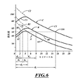
図6および7は、RFエネルギーによる表面および深部加熱、および切除アセンブリ208の中で冷却剤を循環させることによる表面冷却によって生じる効果を示す。冷却剤は、切除アセンブリ208の冷却部209に触れる組織が冷却されるように、熱エネルギーを吸収する。冷却部209は、切除アセンブリ208と神経または他の標的組織との間の組織への損傷を制限または防止するように、気道壁100から十分な量の熱エネルギーを吸収することができる。
FIGS. 6 and 7 illustrate the effects caused by surface and deep heating with RF energy and surface cooling by circulating coolant in the
図6は、摂氏度単位の組織の温度に対応する長手軸とともに、ミリメートル単位の電極アセンブリ214と接触または近接する点から組織の中への深さに対応する横軸を有するグラフを示す。図中の温度は、他に示されない限り、摂氏度である。グラフ上の点「0」は、電極アセンブリ214と気道壁の組織との間の接触点または領域に対応する。3つの曲線A、B、およびCがグラフに示されており、組織の中へ送達されている3つの異なる出力レベルの無線周波数エネルギーに対応する。グラフ上の温度は、最大約100℃である。RF切除中の組織温度の上限であると見なされるため、約100℃またはわずかに下回る温度が示されている。約90℃で、組織液が沸騰し始め、組織が凝固して炭化し、それにより、そのインピーダンスを多いに増加させ、気道壁の組織の中へRFエネルギーを移送する能力を損なう。したがって、組織温度を約90℃以下にとどまらせることが望ましくてもよい。少なくとも50℃で、線216は、それ以上で組織細胞死が発生し、それ以下で組織が大幅な長期効果を被らない(またはいずれの長期効果も被らない)温度を表す。
FIG. 6 shows a graph having a longitudinal axis corresponding to the temperature of the tissue in degrees Celsius and a horizontal axis corresponding to the depth into the tissue from the point of contact or proximity to the
図6に示される曲線Aは、比較的低い電力レベル、例えば、約10ワットのRFエネルギーでの電極アセンブリ214の冷却を伴って、および伴わずに発生するものを表す。曲線Aは、3つの線分A1、A2、およびA3に分けられる。破線分A2は、冷却が適用されない時の指数曲線A3の継続を表す。曲線Aによって分かるように、冷却がない電極・組織界面の温度は、80℃に達し、気道100の組織の中への距離が増加するにつれて指数関数的に減少する。示されるように、曲線A3は、約5ミリメートルの深さにおいて、線216によって表される50℃組織細胞死境界を越える。したがって、電極冷却がないと、発生する細胞死の深さは、距離d1によって表されるように約5ミリメートルとなる。さらなる細胞死は、この電力レベルで停止する。
Curve A shown in FIG. 6 represents what occurs with and without cooling of the
活性冷却が採用される場合、温度は、はるかに低いレベル、例えば、0ミリメートルの距離にある電極・組織界面において曲線A1によって表される約35℃まで降下する。この温度が50℃を下回るため、曲線A2が50℃における細胞死線を越える点でのd2の距離、例えば、表面から3ミリメートルの深さまで、細胞死は始まらない。細胞死は、距離d3によって表されるように、3ミリメートルから5ミリメートルの深さで発生する。そのような冷却切除手技は、上皮および上皮のすぐ下に位置する組織を破壊することなく、細胞死および組織破壊が電極・組織界面からある距離(または一連の距離)を置いて発生することを可能にするため、有利である。いくつかの実施形態では、支質および平滑筋細胞等の上皮または基礎構造を損傷させることなく、気道の外側に沿って走る神経組織を切除することができる。 When active cooling is employed, the temperature drops to a much lower level, eg, about 35 ° C. represented by curve A1 at the electrode-tissue interface at a distance of 0 millimeters. Since this temperature is below 50 ° C., cell death does not begin until the distance d2 at which the curve A2 exceeds the cell death line at 50 ° C., eg, to a depth of 3 millimeters from the surface. Cell death occurs at a depth of 3 to 5 millimeters, as represented by the distance d3. Such cold ablation procedures allow cell death and tissue destruction to occur at a distance (or a series of distances) from the electrode / tissue interface without destroying the epithelium and the tissue located immediately below the epithelium. It is advantageous to make it possible. In some embodiments, neural tissue that runs along the outside of the airway can be excised without damaging epithelium or underlying structures such as stroma and smooth muscle cells.
曲線Bは、比較的高い電力レベル、例えば、20ワットのRFエネルギーでの電極の冷却を伴って、および伴わずに発生するものを表す。曲線Bの線分B2は、冷却を伴わない線分の指数曲線B3の継続を表す。図に示されるように、電極・組織界面における温度は、100℃に達し、それは、組織液の沸騰および組織・電極界面における組織の凝固および炭化が発生し、したがって、組織インピーダンスを有意に増加させ、気道壁の中へ付加的なRFエネルギーを送達する能力を損なう温度であるため、望ましくない場合がある。能動冷却を提供することによって、曲線B1は、電極・組織界面における温度が約40℃まで降下することと、細胞死がd4によって表されるような2ミリメートルの深さから、曲線B3が50℃組織細胞死境界を越える、約8ミリメートルの深さまでで発生することとを示す。したがって、望ましくない高温(例えば、電極・組織界面における組織の凝固および炭化をもたらす温度)に達することなく、より高い電力レベルを使用して、細胞死のはるかに深く大きい領域を提供することが可能であることが分かる。システムは、表面が破壊される必要がないように、気道の上皮表面より下側で細胞死を達成し、したがって、治療からの患者による早期回復を促進するために使用することができる。 Curve B represents what occurs with and without cooling of the electrode with relatively high power levels, eg, 20 watts of RF energy. Line segment B2 of curve B represents the continuation of exponential curve B3 of the line segment without cooling. As shown in the figure, the temperature at the electrode-tissue interface reaches 100 ° C., which causes boiling of the tissue fluid and coagulation and charring of the tissue at the tissue-electrode interface, thus significantly increasing the tissue impedance, This may be undesirable because the temperature impairs the ability to deliver additional RF energy into the airway wall. By providing active cooling, curve B1 has a curve B3 of 50 ° C., since the temperature at the electrode-tissue interface drops to about 40 ° C. and the depth of 2 millimeters as cell death is represented by d4. It occurs at a depth of about 8 millimeters beyond the tissue cell death boundary. Thus, higher power levels can be used to provide a much deeper and larger area of cell death without reaching undesirably high temperatures (eg, temperatures that cause tissue coagulation and charring at the electrode-tissue interface). It turns out that it is. The system can be used to achieve cell death below the epithelial surface of the airway so that the surface does not need to be destroyed, and thus promote early recovery by the patient from treatment.
曲線Cは、なおもより高い電力レベル、例えば、40ワットのRFエネルギーを表す。曲線Cは、線分C1、C2、およびC3を含む。破線分C2は、指数曲線C3の継続である。線分C2は、電極・組織界面における温度が100℃をはるかに超え、能動冷却がないと望ましくないことを示す。能動冷却を用いると、電極・組織界面における温度は、80℃に達し、徐々に増加して95℃に達し、次いで、距離d6によって表される気道の上皮表面における電極・組織界面から約15ミリメートルの距離で、50℃細胞死線216を越えるように指数的に降下する。開始温度が50℃細胞死線216を上回るため、組織細胞死は、上皮表面から約15ミリメートルの深さまでで発生し、組織破壊の大きく深い領域を提供する。
Curve C represents still higher power levels, for example 40 watts of RF energy. Curve C includes line segments C1, C2, and C3. The broken line C2 is a continuation of the exponential curve C3. Line segment C2 indicates that the temperature at the electrode-tissue interface far exceeds 100 ° C. and is not desirable without active cooling. With active cooling, the temperature at the electrode / tissue interface reaches 80 ° C. and gradually increases to 95 ° C., then about 15 millimeters from the electrode / tissue interface at the epithelial surface of the airway represented by the distance d6. At a distance of 50 ° C., the
図7は、組織を切除するように、それを通してRFエネルギーが送達される、気道壁の断面での断面温度プロファイルを示す。それらの派生語を含む、「切除する」または「切除」という用語は、限定ではなく、組織の電気的性質、機械的性質、化学的性質、または他の性質の大幅な改変を含む。切除は、組織を破壊すること、または永久的に損傷させる、負傷させる、あるいは外傷を与えることを伴うことができる。例えば、切除は、局部的な組織破壊、細胞溶解、細胞のサイズ縮小、壊死、またはそれらの組み合わせを含んでもよい。肺切除用途との関連で、「切除」という用語は、切除された神経組織を通した電気信号の伝送を実質的に阻止するように、神経組織性質を十分に改変することを含む。 FIG. 7 shows a cross-sectional temperature profile at the cross section of the airway wall through which RF energy is delivered to ablate tissue. The terms “ablate” or “ablation”, including their derivatives, include, but are not limited to, significant alterations in the electrical, mechanical, chemical, or other properties of the tissue. Ablation can involve destroying tissue or permanently damaging, injuring, or trauma. For example, resection may include local tissue disruption, cell lysis, cell size reduction, necrosis, or a combination thereof. In the context of pulmonary resection applications, the term “ablation” includes sufficient modification of neural tissue properties to substantially prevent transmission of electrical signals through the resected neural tissue.
等温曲線は、電力が電極アセンブリ214に引加され、冷却剤(例えば、室温の生理食塩水または冷やした生理食塩水)がバルーン212に送達されたときに、電極・組織表面215から気道壁100の中への異なる深さで電極アセンブリ214において達する温度を示す。「拡張可能要素」または「配備可能要素」との関連での「要素」という用語は、離散要素または複数の離散要素を含む。一例として、拡張可能要素は、単一のバルーン、または相互と流体連通している複数のバルーンとなり得る。
The isotherm curve is that the
電極アセンブリ214の中への電力送達の速度、冷却剤がバルーン212の中へ通される速度、冷却剤の温度、およびバルーン212のサイズを調整することによって、等温線を修正することができる。冷却剤の適正な温度および流速、ならびに電極アセンブリ214への電力送達の速度を選択することによって、等温線A=60℃、B=55℃、C=50℃、D=45℃、E=40℃、およびF=37℃である、温度を達成することが可能である。さらなる調整は、等温線A=50℃、B=47.5℃、C=45℃、D=42.5℃、E=40℃、およびF=37℃である、温度を達成することを可能にする。50℃等温泉内に含有される領域のみが、細胞死を誘発するほど十分に加熱される。いくつかの手技では、気道壁の中で約2mmから約8mmの深さにある組織を切除することができる一方で、気道壁の中で2mm未満の深さにある他の非標的組織は、細胞死を引き起こす温度以下の温度で保たれる。
By adjusting the rate of power delivery into the
図8を参照すると、カテーテルシステム204は、細長いシャフト230を有するカテーテル207に連結される制御モジュール210を含む。バルーン212は、折り畳み状態から図示した拡張状態まで膨張させることができる。バルーン212が膨張するにつれて、電極アセンブリ214を気道壁に向かって移動させることができる。膨張したバルーン212は、それを通してエネルギーが送達される組織の付近で(例えば、組織に近接または接触して)電極アセンブリ214を保持するのに役立つことができる。冷却剤は、バルーン212または電極アセンブリ214、あるいは両方を冷却するように、熱エネルギーを吸収することができる。
Referring to FIG. 8, the
制御モジュール210は、概して、コントローラ244と、流体送達システム246とを含む。コントローラ244は、限定ではなく、1つ以上のプロセッサ、マイクロプロセッサ、デジタル信号プロセッサ(DSP)、フィールドプログラマブルゲートアレイ(FPGA)、および/または特定用途向け集積回路(ASIC)、メモリデバイス、バス、電源、および同等物を含む。例えば、コントローラ244は、1つ以上のメモリデバイスと通信しているプロセッサを含むことができる。バスは、内部または外部電力供給をプロセッサに結び付けることができる。メモリは、例えば、1つ以上のバッファ、レジスタ、ランダムアクセスメモリ(RAM)、および/または読み出し専用メモリ(ROMs)を含む、種々の形態を成してもよい。コントローラ244はまた、画面等のディスプレイ245と、入力デバイス250とを含んでもよい。入力デバイス250は、キーボード、タッチパッド、または同等物を含むことができ、カテーテル207を制御するようにユーザによって操作することができる。
The
コントローラ244は、異なるプログラムを記憶することができる。ユーザは、組織および所望の標的領域の特性に対処するプログラムを選択することができる。例えば、空気で充填された肺は、比較的高いインピーダンスを有することができ、リンパ節は、中間のインピーダンスを有することができ、血管は、比較的低いインピーダンスを有することができる。コントローラ244は、インピーダンスに基づいて適切なプログラムを決定することができる。性能は、温度、組織インピーダンス、または同等物を検出するセンサからのフィードバックに基づいて最適化することができる。例えば、コントローラ244は、組織温度に基づいて切除アセンブリ208の動作を制御することができる。組織表面温度が過剰に高くなった場合、表面組織を保護しながら深部変状部を生成するために、冷却を増加させることができ、および/または電極電力を減少させることができる。
The controller 244 can store different programs. The user can select a program that addresses the characteristics of the tissue and the desired target area. For example, an air-filled lung can have a relatively high impedance, a lymph node can have an intermediate impedance, and a blood vessel can have a relatively low impedance. The controller 244 can determine an appropriate program based on the impedance. Performance can be optimized based on feedback from sensors that detect temperature, tissue impedance, or the like. For example, the controller 244 can control the operation of the
内部電力供給248(図8の鎖線で図示される)は、無線周波数(RF)発電機等のエネルギー発生器となり得る。RFエネルギーは、所望の周波数で出力することができる。周波数の実施例は、限定ではなく、約50KHZから約1,000MHZの範囲内の周波数を含む。RFエネルギーが組織の中へ方向付けられるときに、エネルギーは、組織内で熱に変換され、組織の温度を約40℃から約99℃の範囲内にさせる。RFエネルギーは、約1秒から約120秒間にわたって引加することができる。いくつかの実施形態では、RF発生器248は、単一のチャネルを有し、約1〜25ワットのRFエネルギーを送達し、連続流能力を保有する。他の範囲の周波数、時間間隔、および電力出力も使用することができる。代替として、内部電力供給248は、1つ以上のバッテリ等のエネルギー貯蔵デバイスとなり得る。電気エネルギーは、電気エネルギーをRFエネルギーまたは別の好適な形態のエネルギーに変換する、電極アセンブリ214に送達することができる。送達されてもよい他の形態のエネルギーは、マイクロ波、超音波、直流、または電磁エネルギーを含む。代替として、極低温切除が利用されてもよい。極低温における流体は、切除アセンブリ208上の極低温熱交換器を冷却するように、シャフト230を通して送達することができる。
The internal power supply 248 (illustrated by the dashed line in FIG. 8) can be an energy generator such as a radio frequency (RF) generator. RF energy can be output at a desired frequency. Examples of frequencies include, but are not limited to, frequencies in the range of about 50 KHZ to about 1,000 MHZ. When RF energy is directed into the tissue, the energy is converted into heat within the tissue, causing the tissue temperature to be in the range of about 40 ° C to about 99 ° C. The RF energy can be applied for about 1 second to about 120 seconds. In some embodiments, the
流体送達システム246は、供給ライン268に連結される流体源260と、帰還ライン272に連結される流体容器262とを含む。流体源260は、筐体ユニット264の中で保持されるコンテナ(例えば、ボトル、キャニスタ、タンク、または流体を保持するための他の種類の容器)を含むことができる。加圧可能な実施形態では、流体源260は、冷却剤を加圧する1つ以上の加圧デバイス(例えば、1つ以上のポンプ、コンプレッサ、または同等物)を含む。温度制御デバイス(例えば、ペルティエデバイス、熱交換器、または同等物)は、流体を冷却または再調節することができる。流体は、生理食塩水、脱イオン水、冷媒、極低温流体、ガス、または同等物を含む、冷却剤となり得る。他の実施形態では、流体源260は、冷蔵冷却剤を保持し、供給ライン268に送達する、絶縁コンテナとなり得る。冷却剤は、送達管腔326に沿って細長いシャフト230を通って遠位に流れ、切除アセンブリ208を充填する。切除アセンブリ208からの冷却剤は、帰還管腔324を介して細長いシャフト230を通って近位に流れ、最終的に容器262に流入する。
The
センサ247(鎖線で図示される)は、コントローラ244に通信可能に連結される。コントローラ244は、センサ247(例えば、圧力センサ、温度センサ、熱電対、圧力センサ、接触センサ、または同等物)からの信号に基づいて、カテーテル207に命令することができる。センサはまた、電極アセンブリ214の上に、細長いシャフト230に沿って、または任意の他の場所に配置することもできる。閉ループ動作モードでは、1つ以上の組織特性、エネルギー分布、組織温度、または任意の他の測定可能な関心のパラメータを示す、1つ以上の信号を伝送(または送信)するように構成することができる、センサ247からのフィードバック信号に基づいて、電気エネルギーを電極アセンブリ214に送達することができる。これらの測定値に基づいて、コントローラ244は、電極アセンブリ214の動作を調整する。開ループ動作モードでは、電極アセンブリ214の動作は、ユーザ入力によって設定することができる。例えば、ユーザは、組織温度またはインピーダンス測定値を観察し、電力レベルを手動で調整することができる。代替として、電力を固定電力モードに設定することができる。さらに他の実施形態では、カテーテルシステム204は、閉ループ動作モードと開ループ動作モードとの間で切り替えることができる。
Sensor 247 (illustrated with a dashed line) is communicatively coupled to controller 244. The controller 244 can command the
図8および9を参照すると、細長いシャフト230は、電力ライン管腔320a−hと、送達管腔326と、帰還管腔324とを含む。電力ライン280a−280h(集合的に「280」)は、それぞれ、電力ライン管腔320a−320h(集合的に「320」)を通って延在し、コントローラ244を電極アセンブリ214に連結する。細長いシャフト230は、全体的または部分的に、1つ以上の金属、合金(例えば、ステンレス鋼等の合金鋼)、プラスチック、ポリマー、およびそれらの組み合わせ、ならびに他の生体適合性材料で作製することができ、高度に分岐した気道に沿って好都合に通過するように可撓性となり得る。
With reference to FIGS. 8 and 9, the
図10および11を参照すると、電力ライン280は、電力供給248から電極アセンブリ214までエネルギーを送達する。いくつかの実施形態では、電力ライン280は、チャンバ234およびバルーン212の外壁を通過する。他の実施形態では、電極アセンブリ214用のコネクタが、チャンバ234内に位置している。電力ライン280は、体液への暴露を回避するように、コネクタと細長いシャフト230との間に延在することができる。
Referring to FIGS. 10 and 11, power line 280 delivers energy from
電極アセンブリ214は、限定ではなく、単極電極、双極電極、金属電極、ワイヤ電極、針電極、または同等物を含むことができ、それぞれ血管または身体構造の周囲の一部分のみに沿って延在する、一連の周囲変状部を形成することができる。身体構造が気道である場合、変状部のそれぞれは、気道の管腔を少なくとも部分的に包囲することができる。変状部は、360度(例えば、約25度から約45度)未満の弧の長さを有することができる。いくつかの実施形態では、変状部は、身体構造の長手軸に対して離間している。一緒に、変状部は所望の周囲を覆う。例えば、変状部は、相互から長手方向に離間している間に、次の変状部の開始部と円周方向に(例えば、身体構造の軸長に沿って見たときに)重複し、それにより、気道(またはその一部分)の周囲全体が治療されていることを確実にすることができる。
The
電極アセンブリ214は、バルーン212の回りに円周方向に離間した電極229を含む。各電極229は、一対の露出電極要素を有する。電極229dの電極要素231dおよび隣接する電極229eの要素231eは、半径方向に隣接する組織を切除するRF弧を協働して形成することができる。電極229は、バルーン212の外面に連結することができる。他の実施形態では、電極229は、バルーン212の側壁に埋め込むか、または別様にバルーン212に固定することができる。
RF電力が組織を通して伝送されるように、隣接する電極229は、一方の電極が正であり、他方の電極が負である双極方式で操作されてもよい。電極229が単極電極である場合、電極は、各電極の独立した制御を可能にするように、別個の電力ライン280に連結することができる。代替として、電極229は、一緒に操作されるように、同じ電力ラインに連結されてもよい。 Adjacent electrodes 229 may be operated in a bipolar manner so that one electrode is positive and the other electrode is negative so that RF power is transmitted through the tissue. If the electrodes 229 are monopolar electrodes, the electrodes can be coupled to separate power lines 280 to allow independent control of each electrode. Alternatively, the electrodes 229 may be coupled to the same power line so that they are operated together.
バルーン212は、全体的または部分的に、ポリマー、プラスチック、シリコン、ゴム、ポリエチレン、ポリ塩化ビニル、化学的不活性物質、無毒物質、電気的絶縁物質、それらの組み合わせ、または同等物で作製することができる。熱伝達を強化するために、バルーン側壁は、高い熱伝導率を伴う1つ以上の伝導性材料を備えることができる。例えば、伝導性片(例えば、金属片)は、もしあれば、高温点から熱エネルギーを奪うのに役立つことができる。バルーン212は、気道表面上の不整形(例えば、軟骨輪、側枝等)に一致することができ、全体的または部分的に、ポリウレタン、または透明、半透明、あるいは不透明であってもよい他の種類の極めて適合性の材料等の、膨張性材料で作製することができる。バルーン212は、ホットドッグ形、卵形、円筒形、または同等物を含む、異なる膨張形状を有することができる。人間の気管支樹を治療するために、膨張したバルーン212の直径Dは、約12mmから約18mmの範囲内となり得る。強化した治療融通性のために、膨張したバルーンの直径は、約5mmから約25mmまでの範囲内であってもよい。バルーン212は、他の動物の他の器官または組織を治療するようにサイズ決定することができる。バルーン212を膨張させるために、図11に示されるように、送達管腔326に沿って、入口ポート225を通して流体が送達される。冷却剤は、チャンバ234内で循環し、次いで、帰還管腔324に沿って近位に流れる。
図12および13は、治療システム200を使用する1つの例示的な方法を示す。気道100治療を行う前、間、および/または後に、治療部位(単数・複数)および非標的組織の場所を特定し、評価するために気道100が視認されることができる。アクセス装置206は、ガイドチューブ、送達鞘、気管支鏡、または内視鏡となり得て、光学視認デバイス(例えば、カメラ)、光学縦列(例えば、一式のレンズ)、および同等物等の1つ以上の視認デバイスを含むことができる。気道神経幹または症状の位置を特定するために、気道の周囲の回りの異なる領域を刺激する(例えば、電気的に刺激する)ことができる。気管支収縮の検出は、その刺激が行われる気道の長さに沿った点よりも遠位の気道平滑筋収縮を測定することによって達成されてもよい。筋収縮は、気道に近接または接触している膨張したバルーンまたは他の種類のセンサの圧力の変化を監視することによって、測定することができる。この技法は、気道狭窄の危険性を低減または排除するために治療される気道の円周方向領域を最小化または制限することができる。神経の場所は、気道神経の位置を特定するために、気道の周囲に沿った点における神経電気信号を測定することによって決定することができる。神経信号増幅を増加させ、気道周囲の付近の気道神経信号の局在性を促進するために、冷気、ヒスタミン、またはフェニルビグアニド等の気道神経信号刺激物が使用されてもよい。
FIGS. 12 and 13 illustrate one exemplary method of using the
図12のアクセス装置206が身体管腔に沿って移動させられるとき、折り畳まれた切除アセンブリ208が作業チャネル386内に保持されている。切除アセンブリ208は、作業管腔386から外へ遠位方向に移動させられ、気道壁の付近に(例えば、気道壁に近接または接触して)電極アセンブリ214を移動させるために膨張させられる。RFエネルギーは、組織(例えば、表面および深部組織)を加熱して標的領域において変状部を形成するように、組織を通って進行することができる。標的領域および関連変状部は、概して、図13および14の鎖線に対応する。
When the
本明細書で使用されるような「変状部」という用語は、永久的に、すなわち、細胞死の点まで損傷させられる組織を指す。場合によっては、エネルギーの送達は、「変状部」と呼ばれる領域の外側の細胞に一時的または非致命的な損傷を引き起こす。例えば、上皮または平滑筋細胞は、本明細書で説明されるエネルギー送達によって一時的に損傷または改変されてもよい。しかしながら、有利に、示差冷却の使用を通して、これらの細胞は、回復し、依然として機能的であることができ、したがって、「変状部」の一部と見なされない。対照的に、切除アセンブリ208は、気道壁の深くに、または気道壁の外側に位置する神経組織または他の標的組織に永久的に損傷させ、したがって、ある肺疾患の原因である神経信号を減衰させることができる。
The term “deformation” as used herein refers to tissue that is permanently damaged, ie, to the point of cell death. In some cases, delivery of energy causes temporary or non-fatal damage to cells outside the region called “deformation”. For example, epithelial or smooth muscle cells may be temporarily damaged or altered by energy delivery as described herein. However, advantageously, through the use of differential cooling, these cells can recover and still be functional and are therefore not considered part of the “deformation”. In contrast, the
図13の冷却部209は、エネルギーが電極アセンブリ214によって出力されている間に組織を冷却するよう、気道壁100に接触する。RFエネルギーによる、この表面および深部加熱と、循環冷却剤による表面冷却との正味の効果は、気道壁100の外層の中の熱の集中である。結合組織の温度は、上皮、支質、および/または平滑筋の温度よりも高くなり得る。一例として、結合組織の温度は、神経幹組織または他の深部組織への損傷を引き起こすように十分高くなり得る一方で、気道の他の非標的組織は、非標的組織への損傷を防止または制限するようにより低い温度で保たれる。
The
図13および14は、8つの別個の変状部237a−h(集合的に「237」)を示す。隣接する変状部237は、切除アセンブリ208の長手軸233に沿って相互から軸方向にオフセットされている。各変状部237は、図14に示されるように、一連の変状部が気道壁100の実質的に全周囲の回りに延在するように、約45度の弧の長さを有することができる。露出電極要素の長さは、変状部237の幅に対応する。露出電極要素の長さ(例えば、電極要素231d、231eの長さ)は、変状部237の所望の幅に基づいて選択することができる。有利に、変状部237は、同時に形成することができる。例えば、切除治療の間に切除アセンブリを移動させなければならないことを回避するように、変状部237の全体または大部分を同時に形成することができる。他の実施形態では、変状部を連続的に形成するように、異なる電極229を起動することができる。電極アセンブリ214は、異なる組織を切除するように、異なる場所に移動させることができる。このようにして、所望の治療に基づいて、同時に、または連続的に、1つ以上の変状部を実施することができる。
FIGS. 13 and 14 show eight
従来の切除カテーテルを用いると、切除過程は、局所気道狭小または狭窄を引き起こす場合がある、瘢痕輪を引き起こすように十分であってもよい。変状部237が気道の長さに沿った異なる場所にあるため、狭窄の影響を軽減することができる。図示した実施形態は、瘢痕組織の連続輪の形成を回避しながら、気道の神経を麻痺させるのに適している。気道100の内周の回りに360度延在する、瘢痕組織の連続輪は、気道管腔の断面積を有意に減少させ、次いで、空気流抵抗を有意に増加させる場合がある。ねじれ形変状部237は、気道管腔の断面積の縮小を軽減するのに役立つ。
With conventional ablation catheters, the ablation process may be sufficient to cause scarring, which may cause local airway narrowing or stenosis. Since the deformed portion 237 is at different locations along the length of the airway, the effect of stenosis can be reduced. The illustrated embodiment is suitable for paralyzing airway nerves while avoiding the formation of a continuous ring of scar tissue. A continuous ring of scar tissue that extends 360 degrees around the inner circumference of the
図14は、変状部237の場所を示す。気道100の長軸に沿った、長軸に直角な仮想面上への変状部237の外形の投影は、図14に示されるように、実質的に連続的な閉鎖輪を画定することができる。神経幹45が気道100に沿って長手方向に延在するため、変状部237は、神経幹の全てが切除されることを確実にするように十分な深さにあり得る。他の実施形態では、電極アセンブリ214は、気道周囲の一部分のみ、例えば、気道周囲の180度、150度、または130度を治療するために使用することができる。それだけが、効果的に気道100の神経を麻痺させるために必要とされてもよい。したがって、気道壁全体の周囲に延在する変状部を形成することなく、神経信号を効果的に切断することができ、狭窄の形成をさらに低減することができる。
FIG. 14 shows the location of the deformed portion 237. Projection of the contour of deformed portion 237 along a major axis of
RF切除中に、気道壁の内部層(例えば、支質)のうちの1つ以上の中で、または気道壁の内層(例えば、上皮)の中で、熱を集中させることができる。さらに、気管支動脈分岐の血管のうちの1つ以上が、変状部内にあってもよい。たとえ神経組織が動脈分岐の隣にあっても、神経幹組織が損傷されている間に、気管支動脈分岐を通って流れる血液が熱損傷からこれらの分岐を保護するように、電極214を使用して生成される熱を制御することができる。カテーテル207は、細胞死の比較的小さい領域を生成することができる。例えば、気道壁100の中央にある、または気道壁100の外面に沿った組織の2mmから3mmの区画を破壊することができる。電力の適切な引加および適切な冷却によって、任意の所望の深さで変状部を生成することができる。
During RF ablation, heat can be concentrated in one or more of the inner layers (eg, stroma) of the airway wall or in the inner layer (eg, epithelium) of the airway wall. Furthermore, one or more of the blood vessels of the bronchial artery branch may be in the deformed portion.
気道軟骨輪または軟骨層は、典型的には、気道の軟組織(例えば、平滑筋または結合組織)よりも有意に大きい電気抵抗を有する。気道軟骨は、エネルギー流(例えば、電気無線周波数電流)を妨げ、電極が軟骨の隣にあるときに攻撃する気道神経幹に影響を及ぼす無線周波数電気エネルギーを用いて、治療変状部の形成を行う。 The airway cartilage ring or cartilage layer typically has a significantly greater electrical resistance than the airway soft tissue (eg, smooth muscle or connective tissue). Airway cartilage interferes with energy flow (eg, electrical radio frequency current) and uses radio frequency electrical energy to affect the airway nerve trunk that attacks when the electrode is next to the cartilage to form a treatment deformity. Do.
図示したエネルギーエミッタ214は、軟骨間エネルギーエミッタとして機能することができる。電極要素227は、軟骨輪235a、235b(集合的に「235」)の間隔と概して一致するように寸法決定されてもよい。図13に示されるように、変状部237が軟骨輪235の間の空間333内に完全に位置しているように、各電極要素227は、2つの隣接輪235a、235bの間に配置される。
The illustrated
電極229は、空間333の中に電極要素227を優先的に着座させるのに役立ち、したがって、治療を行うこと、または正しい配置を検証することを容易にする、軟骨間ポジショナとしての機能を果たすことができる。例えば、電極要素227は、外向きに突出することができ、空間333の中のより軟質で柔軟な組織の領域の中へ移動し、かつ嵌合する傾向がある。したがって、電極229は、切除アセンブリ208にインデックスを付けるために使用することができる。
The electrode 229 serves to preferentially seat the electrode element 227 in the
図15は、単一の電力ラインによって接続される単極電極である電極を示す。電力は、電極に同時に送達することができる。任意の数の電極をバルーン212に沿って配置することができる。例えば、バルーンの周囲の回りで均等または不均等に電極の1つ以上を離間させることができる。
FIG. 15 shows an electrode that is a monopolar electrode connected by a single power line. Power can be delivered to the electrodes simultaneously. Any number of electrodes can be placed along the
図16は、切除アセンブリ300の長手軸312に対して斜角で配向される電極310a−310c(集合的に「310」)を示す。電力ライン316a−316c(集合的に「316」)は、エネルギーをそれぞれの電極310に提供する。(図示されていないが、他の電極が切除アセンブリ300の非可視的な裏面に位置する。)電極310は、双極電極となり得る。一例として、電極310aは、要素318a、319aの間にRFエネルギーを送達するように、交互に正および負となり得る、電極要素318a、319aを含むことができる。
FIG. 16 shows electrodes 310 a-310 c (collectively “310”) oriented at an oblique angle with respect to the longitudinal axis 312 of the
電極310の間の角度αおよび長手軸312の方向は、形成される変状部の長さ、隣接する変状部の間の所望の円周方向の間隙、および同等物に基づいて選択することができる。図示した角度αは、約45度である。必要または所望であれば、他の角度も可能である。隣接する電極310の間に、治療されていない非損傷組織の領域があり得る。 The angle α between the electrodes 310 and the direction of the longitudinal axis 312 should be selected based on the length of the deformed portion to be formed, the desired circumferential gap between adjacent deformed portions, and the like. Can do. The illustrated angle α is about 45 degrees. Other angles are possible if necessary or desired. There may be untreated areas of undamaged tissue between adjacent electrodes 310.
図16に示されるように、電極または電極対310aによって生成される1つの変状部は、管状身体構造の周囲全体(またはその一部分)が治療されることを確実にするために、円周方向に隣接する電極または電極対310bによって生成される次の変状部の開始部と円周方向に重複する。電極310aによって作られる変状部の一端を通る長手方向に仮想線が引かれた場合、仮想線は、電極310bによって作られる隣接する変状部の近端に交差または近接する。したがって、隣接する変状部の端は、軸312に沿ってオフセットされ、円周方向に重複する。
As shown in FIG. 16, one deformation created by the electrode or
図17は、拡張可能バスケット414および電極413、415を含む切除アセンブリ400を示す。バスケット414は、電極413、415を冷却するために、それを通って冷却剤が流れる中空部材を含む。バスケット414の長手方向長さは、バスケット414が複数の軟骨輪を横断して延在するように選択することができる。電極413、415は、輪の間に配置されることができる。例えば、細長いバスケット414は、少なくとも3つの軟骨輪(図17の垂直鎖線431、432、433によって表される)を横断して延在することができる。電極413は、軟骨輪431、432の間に配置されることができる。電極415は、軟骨輪432、433の間に配置されることができる。バスケット414が配備されたときに、電極413、415の隣接する列の間の距離Dは、概して、軟骨輪の間の距離に対応することができ、それにより、電極413、415を軟骨輪の間に着座させることができることを確実にする。電極413aは、第1の極性を有することができ、電極413bは、エネルギーが電極の間に流れるように反対極性を有することができる。電極対413a、413bは、円周方向に重複し、軸方向に離間した変状部を形成するように、隣接する一対の電極415a、415bから角度的にオフセットされる。重複の距離Dは、気道の周囲全体が治療されることを確実にするために十分であり得る。
FIG. 17 shows an
図18は、それぞれ、管腔427、429に沿い、かつ減圧要素423、425を通って流れる流体を示す。本明細書で使用されるように、「減圧要素」という用語は、限定ではなく、作業流体の圧力を低減するように構成されるデバイスを指す。減圧要素は、作業流体の圧力を、作業流体の蒸発圧力以下まで低減することができる。作業流体は、冷媒(例えば、極低温冷媒または非極低温冷媒)を含むことができる。いくつかの実施形態では、減圧要素は、それを通過する作業流体の少なくとも一部分の蒸発を引き起こす、減圧または拡張弁の形態である。減圧要素は、有効量の作業流体(例えば、冷媒、極低温流体等)を蒸発させて、作業流体の温度を低減する。いくつかのモードでは、要素423、425を通過する重量による作業流体の実質的に全てまたは大部分は、低温の低圧ガスに変換される。いくつかの実施形態では、減圧要素423、425は、ノズル弁、針弁、ジュールトムソンスロットル、スロットル要素、または所望の圧力降下を提供するための任意の他の好適な弁となり得る。例えば、ジュールトムソンスロットルは、流体の膨張から作業エネルギーを回収することができ、より低い下流温度をもたらす。いくつかの実施形態では、減圧要素は、特に作業流体が水等の非冷媒である場合に、流体調節要素(例えば、弁システム)と代替することができる。
FIG. 18 shows fluid flowing along
図18を参照すると、図18の高圧ガスP1は、送達管腔427、429を通過する。高圧ガスP1は、要素423、425を通過し、チャネル436、438に進入し、そこで圧力がP2まで降下する。P1からP2への圧力の降下は、T1からT2へのガスの温度の降下につながる。温度変化の大きさは、以下の式:
Τ1−Τ2=μ(Ρ1−Ρ2)
によって求められ、
式中、
Tは、ガスの温度であり、
Pは、ガスの圧力であり、
μは、ガスのジュールトムソン係数であり、
下付き文字1は、高圧状態を表し、
下付き文字2は、低圧状態を表す。
Referring to FIG. 18, high pressure gas P 1 of FIG. 18 passes through
1 1 −Τ 2 = μ (Ρ 1 −Ρ 2 )
Sought by
Where
T is the temperature of the gas,
P is the pressure of the gas,
μ is the Joule-Thomson coefficient of the gas,
The subscript 1 represents the high pressure state,
The
図19および20と関連して論議されるように、チャネル436、438の中のガスが通気口を通って退出し、周囲の圧力まで降下すると、第2の圧力降下が発生し得る。切除アセンブリ400が呼吸器系で使用される場合、周囲の圧力は、大気圧である。この温度降下は、
Τ2−Τ3=μ(Ρ2−ΡΑΤΜ)
である。
As discussed in connection with FIGS. 19 and 20, a second pressure drop can occur as the gas in
Τ 2 −Τ 3 = μ (Ρ 2 −Ρ ΑΤΜ )
It is.
ジュールトムソン係数(μ)は、各ガスまたはガス混合物に特異的である。μに対する標準温度値は、
二酸化炭素について
The Joule-Thomson coefficient (μ) is specific for each gas or gas mixture. The standard temperature value for μ is
About carbon dioxide

これらの係数は、所与の圧力降下について、CO2が、空気が経験する同様の圧力の降下よりも5倍大きい温度の降下を引き起こすことを示す。 These factors indicate that for a given pressure drop, CO 2 causes a temperature drop that is five times greater than the similar pressure drop experienced by air.
肺の中の空気の使用が望ましくなり得る。保冷剤ガスの流速が、肺から外へ二酸化炭素を換気する被検体の能力を圧倒しないよう十分に低い場合、この付加的な二酸化炭素を使用することができる。冷却剤導管の中の冷却剤が、液体空気または液体CO2等の高圧液体である場合に、冷却効果を強化することができる。高圧液体は、減圧要素(例えば、スロットル)を通過し、ガスの温度を高圧液体の温度よりも低くさせる、高圧液体から高圧ガスへの吸熱相変化を受ける。それは次いで、図19および20と関連して論議されるように、通気口441を介して放出される前に、温度のさらなる降下を引き起こす、P1からP2へのジュールトムソン膨張を受ける。
The use of air in the lungs may be desirable. This additional carbon dioxide can be used if the flow rate of the cryogen gas is low enough not to overwhelm the subject's ability to vent carbon dioxide out of the lungs. Coolant in the coolant conduit, if it is high-pressure liquid in the liquid air or the like liquid CO 2, it is possible to enhance the cooling effect. The high pressure liquid passes through a decompression element (eg, a throttle) and undergoes an endothermic phase change from the high pressure liquid to the high pressure gas that causes the temperature of the gas to be lower than the temperature of the high pressure liquid. It then undergoes a Joule Thompson expansion from P 1 to P 2 that causes a further drop in temperature before being released through
図19および20は、以下で詳述されるものを除いて、図17および18の切除アセンブリ400と略同様である、切除アセンブリ437を示す。切除アセンブリ437は、細長い部材に沿って位置している一連の開口部または通気口439を含む。細長い部材を通って流れる冷却剤は、開口部439から外へ出て、隣接する組織を冷却することができる。加えて、遠位端443に位置している開口部または通気口441は、冷却剤を放出することができる。図20に示されるように、矢印によって表される冷却剤は、通気口439、441から外へ出ることができる。このようにして、冷却剤は、切除アセンブリ437を冷却することができ、直接組織冷却を提供することができる。通気口441は、随意で、上記で説明されるように、好適な圧力降下を提供して、ジュールトムソン膨張から冷却剤を蒸発させ、それにより、冷却剤温度を低下させるように構成されてもよい。
19 and 20 illustrate an
図21は、拡張可能部材453に沿って円周方向に離間したV字形電極を有する、切除アセンブリ450を示す。電極455は、隣接する電極455の先端459と重複する端456、457を有する。電極は、V字形変状部を形成するように気道周囲に沿って同様に離間した、V字形標的領域にエネルギーを出力することができる。V字形変状部の間の未治療組織は、瘢痕組織または狭窄により、管腔気道が有意に狭くならないことを確実にするのに役立つことができる。
FIG. 21 shows an
図22は、T字形電極を携持する拡張可能要素462を含む、切除アセンブリ460を図示する。電極463は、隣接する電極467の端465と重複する自由端464を有する。円周方向に整列した電極461は、複数の略T字形の変状部を形成することができる。他の実施形態では、電極は、U字形、S字形、W字形、L字形、または任意の他の好適な形状となり得る。加えて、これらの実施形態のうちのいずれかでは、電極は、図16に示されたものと同様の斜交または螺旋パターンで長手方向に変位されてもよい。
FIG. 22 illustrates an
図23は、軟骨輪513、515(鎖線で図示される)の間に電極512を配置することができる、第1組の細長い部材511a−511d(集合的に「511」)を含む、切除アセンブリ500を示す。細長い部材521a−521d(集合的に「521」)は、軟骨輪515、518の間に位置している電極523a、523b、523c、523d(集合的に「523」)を携持する。電極512は、輪513、515の間に変状部を形成する。電極523は、輪515、518の間に変状部を形成する。細長い部材511、521は、気道壁に対して電極を配置するように半径方向外向きに付勢される、可撓性かつ弾性のロッドまたはワイヤであってもよく、気道壁の異なる周囲領域が各電極対で治療されるように、電極512に対して円周方向にオフセットした位置に電極523を配置するように構成されてもよい。1つのコラーゲン間空間の中の変状部の一端は、隣接するコラーゲン間空間の中の隣接する変状部と円周方向に重複することができる。したがって、変状部は、相互から軸方向に離間するが、身体管腔に対して円周方向に重複し得る。細長い部材511、521は、気道の中へ導入するために好適な半径方向収縮構成に折り畳むように、管状鞘510の中へ後退させられてもよい。
FIG. 23 illustrates an ablation assembly that includes a first set of
図24は、拡張可能エネルギーエミッタアセンブリ610を伴う切除アセンブリ600を示す。拡張可能電極アセンブリ623は、バルーンとして図示される拡張可能部材620の全体または大部分を取り囲むことができる。絶縁体625は、電極アセンブリ623の一部分を覆って端の間に延在する。電極623は、拡張を可能にするように、ジグザグ構成(図示されている)、蛇行性構成、または波形構成を有することができ、バルーン620の回りに約90度から約360度延在することができる。使用中、露出電極623は、治療される気道の領域、例えば、神経幹がしばしば位置する後部側に対面することができる。代替として、エミッタアセンブリ610は、離散変状部を生成するように、絶縁部分によって分離される複数の露出電極を含むことができる。
FIG. 24 shows an
随意で、第2のエネルギーエミッタ618は、エネルギーエミッタ610の遠位に位置している。エネルギーエミッタ618は、露出電極621と、絶縁体623とを有する。電極621は、電極623と協働して、円周方向にオフセットし、軸方向に離間した相補(例えば、重複)変状部を形成することができる。例えば、電極623は、気道壁の上部分に沿って約180度の弧の長さを有する、変状部を形成することができる。電極621は、気道壁の下部分に沿って約180度の弧の長さを有する、変状部を形成することができる。一緒に、2つの変状部は、気道壁の周囲全体の回りに延在する。変状部は、同時に、または連続的に生成することができる。
Optionally, the
図25は、拡張可能要素712に包み込まれた電極アセンブリ710の形態のエネルギーエミッタを含む、切除アセンブリ700を示す。電極アセンブリ710は、導管731と、複数の電極715a−h(集合的に「715」)とを含む。電極715は、同時に、または連続的に変状部を形成することができる。
FIG. 25 shows an
図26を参照すると、電極715aは、バルーン712が膨張させられると、略円周方向に配向される、中空管状金属部材となり得る。導管731は、電極716を通って連続的に冷却剤(食塩水または他の冷却剤)を送達する。
Referring to FIG. 26, the
バルーン712および導管731を通して、異なる冷却剤を送達することができる。冷却剤は、導管731を通る送達管腔761を通って流れ、電極715を冷却することができる。別の冷却剤が、送達管腔751を通ってバルーン712に流入することができる。バルーン712および導管731の中の冷却剤は、帰還管腔739を介して近位に流れることができる。他の実施形態では、冷却剤は、電極アセンブリ710およびバルーン712を通って連続的に流れる。
Different coolants can be delivered through
別個のワイヤペアを、各電極715に電気的に連結することができる。各電極715は、独立して操作することができる。他の実施形態では、電極715は、双極性であり、反対極性のペアで配設される。以前の実施形態に関して論議されるように、電極715は、コラーゲン間空間内で変状部を形成するように、相互に対して配向し、配置することができる。2009年5月8日出願の米国特許出願第12/463,304号、および2010年10月27日出願の米国特許出願第12/913,702号が、それらの全体で参照することにより組み込まれ、切除アセンブリ700とともに使用することができる、技法、材料、カテーテル、および構成要素を開示している。
A separate wire pair can be electrically coupled to each electrode 715. Each electrode 715 can be operated independently. In other embodiments, the electrodes 715 are bipolar and are arranged in pairs of opposite polarity. As discussed with respect to previous embodiments, the electrodes 715 can be oriented and positioned relative to each other to form a deformity within the intercollagenous space. US patent application Ser. No. 12 / 463,304, filed May 8, 2009, and US Patent Application No. 12 / 913,702, filed October 27, 2010, are incorporated by reference in their entirety. , Techniques, materials, catheters, and components that can be used with the
電極715a−hは、いくらかの重複にもかかわらず、相互から円周方向にオフセットされ、かつ相互から軸方向にオフセットされる変状部を生成するように、螺旋導管731に沿って配設される。電極715a−hのそれぞれを通る軸方向(軸719と平行)に引かれた仮想線は、電極715a−hのうちの別の電極に交差し、気道の周囲全体が治療されることを確実にする。有利に、電極は、それらが生成する変状部が気道に沿って長手方向に分離され、したがって、狭窄が結果として生じる可能性を低減するように、螺旋導管731に沿って離間している。
The
変状部の形状は、冷却剤の温度、冷却剤の流速、冷却剤の熱運搬能力、バルーンの熱特性(例えば、バルーンの熱伝達性質)、または送達された電力の量を調整することによって制御することができる。図27A−31Bは、温度プロファイル、およびバルーンによる次第に増加した冷却によって形成される対応する変状部を示す。バルーンの冷却能力は、冷却剤温度を減少させることによって、または冷却剤の流速を増加させることによって、あるいは両方によって増加させることができる。変状部の成形はまた、電極の冷却剤容量を変化させながら、バルーンの冷却能力を略一定に保つことによって、または組織に送達される電力を増加または減少させることによって達成することもできる。一例として、図25の切除アセンブリ700は、図27B、27C、28B、29B、30B、および31Bの変状部を形成するために使用することができる。バルーン712が電極チャネル753よりも大きい直径を有するため、電極715aを通る高い流速と比較して、バルーン表面に沿って比較的低い流速がある。これは、示差冷却をもたらす。電極715aおよびバルーン712が独立した流動を有する場合、冷却剤は、示差冷却のための異なる温度および/または流速にあり得る。
The shape of the deformed portion can be adjusted by adjusting the coolant temperature, coolant flow rate, coolant heat carrying capacity, balloon thermal properties (eg balloon heat transfer properties), or the amount of power delivered. Can be controlled. FIGS. 27A-31B show the temperature profile and the corresponding deformation formed by the incremental cooling by the balloon. The cooling capacity of the balloon can be increased by decreasing the coolant temperature, or by increasing the coolant flow rate, or both. Deformation can also be achieved by changing the coolant volume of the electrode while keeping the balloon's cooling capacity substantially constant, or by increasing or decreasing the power delivered to the tissue. As an example, the
図27Aは、80℃、60℃、および40℃の等温線、および組織中の温度分布を示す。図27Bは、図27Aの等温線に対応する変状部804を示す。冷却チャネル753の中の冷却剤は、有意量の熱を吸収する唯一の冷却剤である。バルーン712は、有意量の熱エネルギーを吸収せず、室温と略等しく、約20℃〜30℃の範囲内の温度の流体で充填することができる。いくつかの実施形態では、バルーン712は、周囲空気で膨張させられ、組織825に対して電極715aを保持することができる。他の実施形態では、バルーン712は、温生理食塩水で膨張させられる。変状部804は、略半円形を有する。半径rおよび深さDは、それぞれ、冷却チャネル753の中の冷却剤の温度を減少または増加させることによって、増加または減少させることができる。加えて、または代替として、半径rおよび深さDは、それぞれ、冷却剤の流速を減少または増加させることによって、増加または減少させることができる。
FIG. 27A shows isotherms at 80 ° C., 60 ° C., and 40 ° C., and the temperature distribution in the tissue. FIG. 27B shows a
組織表面825における変状部の断面幅を縮小するように、バルーン712を通して冷蔵冷却剤を送達することができる。図28Aおよび28Bは、冷却剤が電極715aを冷却する時、および低温冷却剤がバルーン712を通って低速で流れる時の等温線、および対応する略楕円形の変状部804を示す。バルーン712の中の冷却剤は、バルーン・組織界面に接触または近接する組織を保護するように、有意量の熱エネルギーを吸収する。図28Bの図示した実施形態を含む、いくつかの実施形態では、表面825における変状部804の断面幅は、表面825における図27Bの変状部804の断面幅よりも小さい。図28Bの変状部804の断面幅は、深さとともに最大幅WMaxまで増加し、次いで、最深領域830まで減少する。最大幅WMaxは、変状部804の深さDよりも小さい。図28Bは、電極幅のわずか約150%である幅を有する、表面825における変状部804を示す。
Refrigerated coolant can be delivered through the
図29Aおよび29Bは、低温冷却剤がバルーン712を通って高速で流れる、または超低温冷却剤がバルーン712を通って低速で流れる時の等温線および変状部804を示す。いくぶん涙滴形の変状部804が、組織表面825から延在する。変状部804の浅部または狭小領域834の幅は、電極715aの断面幅WEとほぼ等しい。したがって、表面825における変状部804は、電極・組織界面のわずか約150%である最大断面幅を有する。これは、最小量の組織表面が損傷されることを確実にする。変状部804は、浅い部分834から拡大領域835へと外向きに先細になる。変状部の断面幅は、深さとともに最大幅WMaxまで徐々に増加する。最大幅WMaxは、表面825における断面幅の約1倍から約5倍以上となり得る。変状部804の最深領域830は、部分的に円形の形状を有する。
FIGS. 29A and 29B show isotherms and
図30Aおよび30Bは、等温線、および超低温冷却剤がバルーン712を通って高速で流れるときに形成することができる涙滴形の変状部804を示す。変状部804は、組織表面825から延在し、広い深部領域852へと外向きに急速に拡張する、狭い浅部領域834を有する。浅部領域834の幅は、電極715aの幅WEよりも小さい。断面幅は、深さとともに最大幅WMaxまで急速に増加する。したがって、変状部804の容量の大部分は、組織の中の深くにある。
FIGS. 30A and 30B show an isotherm and a teardrop shaped
図31Aおよび31Bは、等温線、および超低温冷却剤がバルーン712を通って超高速で流れるときに形成することができる、対応する円形の変状部804を示す。変状部804は、組織表面825からの深さDで配置される。変状部804の最大断面幅WMaxは、深さDWidth Maxにある。変状部804は、電極・組織界面から離間し、冷却剤の流速および温度に応じて異なる形状を有することができる。略楕円形、細長い形状、または同等物等の、他の埋設変状部形状を達成するために、示差冷却を使用することができる。
FIGS. 31A and 31B show isotherms and corresponding
DWidth Maxは、標的領域の場所に基づいて選択することができる。神経組織を損傷させるために、DWidth Maxは、変状部が神経組織を含むことを確実にするように、および平滑筋組織への有意量の損傷を軽減または回避するように、少なくとも約2mmとなり得る。そのような実施形態は、平滑筋組織が、典型的には、2mmの深さより下側にないので、気道壁を治療することに適している。このようにして、標的領域の断面幅は、平滑筋組織よりも深い深さにおいて最大化することができる。変状部の大部分、およびいくつかの実施形態では実質的に全体は、典型的には、平滑筋組織の領域よりも深く気道壁の中に位置する、平滑筋組織ではない組織の中に生じる。さらに、気道壁の中の平滑筋細胞への損傷は、神経組織を損傷させることなく、例えば、喘息、COPD、または他の肺疾患の結果として、気道の反応性または収縮を大幅に改変するために必要とされる損傷の量よりも少なくなり得る。 The D Width Max can be selected based on the location of the target area. To damage nerve tissue, the D Width Max is at least about 2 mm to ensure that the deformity includes nerve tissue and to reduce or avoid significant amounts of damage to smooth muscle tissue. Can be. Such an embodiment is suitable for treating airway walls because smooth muscle tissue is typically not below 2 mm deep. In this way, the cross-sectional width of the target region can be maximized at a depth deeper than the smooth muscle tissue. Most of the deformities, and in some embodiments, substantially entirely, are typically in tissue that is not smooth muscle tissue, located deeper in the airway wall than the region of smooth muscle tissue. Arise. Furthermore, damage to smooth muscle cells in the airway wall can significantly alter airway responsiveness or contraction, for example, as a result of asthma, COPD, or other pulmonary disease, without damaging neural tissue. Can be less than the amount of damage required.
変状部は、有意量の組織が永久的に損傷されない保護領域によって、組織表面から分離されることができる。図31Bおよび32Bは、深さDPを有する保護領域861を示す。有利に、保護領域861中の有意量の組織が永久的に損傷されないので、組織機能を保つことができる。深さDPは、神経組織を切除するために、少なくとも約1mmから約2mmとなり得る。
The deformities can be separated from the tissue surface by a protective area where a significant amount of tissue is not permanently damaged. Figure 31B and 32B show a
図32は、曲線(螺旋形状として図示される)本体910(気道の先細に合致するように先細に示される)と、電極912a、912b、912c(集合的に「912」)とを含む、螺旋切除アセンブリ900を示す。随意で、冷却剤の温度を低減するジュールトムソンスロットルとしての役割を果たすように、1つ以上の減圧要素を本体910内に配置することができる。
FIG. 32 shows a helix comprising a curved (shown as a spiral shape) body 910 (shown tapered to match the taper of the airway) and
電極912は、相互と略同様となり得て、したがって、他に示されない限り、1つの電極の説明は、他の電極に等しく該当する。電極912aは、複数の通気口916、918を含む。矢印によって表される冷却剤は、通気口916、918から流出することができる。電極912aは、本体910の外面に連結することができる。これは、電極912が、組織と物理的に接触するように、十分な距離で外向きに突出することを可能にする。電極912は、相互から円周方向にオフセットされるが、それらの縁においていくらかの円周方向の重複を有する変状部を生成するように配設され、すなわち、1つの変状部の端を通って気道の下へ長手方向に引かれた仮想線が、次の変状部の端に交差する。電極912が螺旋本体910に沿って離間しているので、それらが生成する変状部も気道の中で軸方向に離間し、したがって、狭窄の可能性を低減する。
The electrodes 912 can be substantially similar to each other, and thus the description of one electrode applies equally to the other electrode, unless otherwise indicated. The
本体910は、起動されたときに螺旋またはコルクスクリュー形状に成形することができる、Nitinol等の可撓性かつ伝導性材料を含んでもよい。本体910を通して温かい流体を送達することができ、本体910を送達構成(例えば、直線構成)から配備構成(例えば、コルクスクリュー構成または螺旋構成)まで移動させる。他の実施形態では、本体910は、配備構成に向かって付勢することができ、かつ配備構成を呈するようにスリーブまたは作業管腔から外へ送達することができる。切除アセンブリ900は、切除アセンブリ900を送達構成に戻すために、スリーブまたは作業管腔の中へ近位に引き入れることができる。他の実施形態では、本体910に異なる構成を呈させるために、テンショナ、引張ワイヤ、引張ロッド、または同等物を使用することができる。
The
随意で、内部領域920を通して、バルーンを配置することができる。略円錐形バルーン、円筒形バルーン、ホットドッグ形バルーン、または他の好適な形状のバルーンが、内部領域920の中へ挿入可能であってもよい。
Optionally, a balloon can be placed through the
図33は、絶縁領域962a、962b、962cを作成するように介在部を覆う絶縁カバーを伴って、電極960a、960b、960c(集合的に「960」)を形成する一連の離間した露出部を有する、管状伝導性内側部材でできている螺旋切除アセンブリ952を示す。冷却剤は、電極960を冷却するように切除アセンブリ520を通して循環させることができる。付加的な組織冷却を提供するために、随意で、内側管状部材および/または絶縁カバーの中の通気口(図示せず)から外へ冷却剤を送達することができる。
FIG. 33 illustrates a series of spaced exposed
図34は、一連の離間した双極電極1010a−f(集合的に「1010」)を含む、切除アセンブリ1000を示す。電極は、変状部が各双極対の間で対角線上に生成されるように、反対極性のペアで配設される。電極1010は、軟骨輪を横断する斜交変状部を形成することができる。図35に示されるように、切除アセンブリ1000は、気道1012内に位置している。電極1010は、輪の間に位置している。電極1010a−cは、図36の変状部1030を生成することができる。変状部1030の端1032は、輪1034に近接する。対向する端1036は、輪1038に隣接する。端1032、1036は、気道1012に沿って軸方向に相互から変位させられる。図36に示されるように、端1032、1036の軸方向変位は、端1032、1036の間の円周方向距離よりも有意に大きい。ある手技において、端1032、1036の間の距離は、少なくとも1ミリメートル、5ミリメートル、10ミリメートルである。いくつかの実施形態では、端1032、1036の間の軸方向距離は、隣接する軟骨輪の間の距離よりも大きい。これは、変状部が輪を横断することを確実にする。
FIG. 34 shows an
図36の変状部1030の中央部は、輪1034、1038の間の輪1040を横断する。切除アセンブリ1000の裏面上の電極1010d、1010e、1010fは、変状部1041を形成する。図示された変状部1041、1030は、反対側に、かつ気道に沿った異なる軸方向の場所にある。
The center of
電極1010は、気道組織を相互作用して軟骨輪の間に位置する電極1010を保つように十分な距離で外向きに突出することができる。双極モードで動作する時、変状部が形成され、輪を横断する。変状部を形成した後、カテーテルを近位に引くか、遠位に押し、軸方向にオフセットした変状部を形成するために使用することができる。加えて、または代替として、気道1012に沿った異なる角度位置で斜交変状部を形成するように、カテーテルを回転させることができる。図36の変状部は、連続の変状部として図示されている。他の実施形態では、変状部は、複数の離散した離間変状部を含むことができる。例えば、変状部1030は、一連の離間変状部を含むことができる。
図37および38は、内部ジェットによって冷却される、円周方向にオフセットし、軸方向に離間した電極1050a、1050bを示す。冷却剤は、送達管腔1052を通って流れ、ポート1054から退出する。冷却剤のジェットは、開放冷却チャネル1056に沿って流れ、電極1050aを冷却する。冷却剤は、出口ポート1062a、1062bを介してチャンバ1060から退出する。冷却剤は、帰還管腔1072に沿って流れる。電極1050a、1050bは、冷却されている間に単極モードまたは双極モードで操作することができる。
Figures 37 and 38 show circumferentially offset and axially spaced
図39A−40Bは、電極アセンブリ1082の形態のエネルギーエミッタを含む切除アセンブリ1080を示す。電極アセンブリ1082は、変状部1083(図39Bおよび40B)を形成することができる一連の電極1084a−f(集合的に「1084」)を含む。広範囲の異なる種類の蛇行性、曲線、ジグザグ、z字形、または他の種々の構成である。図示される変状部1083は、略螺旋の形状を有し、複数の軟骨輪を横断する。切除アセンブリ1080は、任意の種類のこれらの種類の電極アセンブリ1082を有することができる。例えば、一対の螺旋切除アセンブリ1082を切除アセンブリ1080の外側に配置することができる。
FIGS. 39A-40B illustrate an ablation assembly 1080 that includes an energy emitter in the form of an
図示される変状部1083は、連続的であり、気道の長軸1089に沿って軸方向に離間した端1085、1087を有する。端1085、1087はまた、相互から角度的にオフセットされている。図39Bおよび40Bに示されるように、軸1089に沿った端1085、1087の間の距離は、隣接する輪の間の距離よりも大きい。このようにして、変状部1083は、複数の輪を横断する。
The illustrated
電極1084は、略連続した変状部1083を形成するためにともに接近することができる。他の実施形態では、電極1084の間の距離は、複数の離間変状部を提供するために増加させることができる。離間変状部は、変状部1083と同様の形状を有するように配設することができるが、他の形状および変状部パターンが可能である。
The electrodes 1084 can be approached together to form a substantially continuous
図41は、バルーン1111に巻き付いている電極アセンブリ1110を有する切除アセンブリ1100を示す。電極アセンブリ1110は、冷却剤を含有するために好適な管1113を備え、バルーン1111の内部と連通している遠位端1115を有する。電極は、管1113の外部に取り付けられ、接着され、塗装され、または別様に連結される。このようにして、冷却剤は、電極を冷却するために、そこから冷却剤が管1113を通って流れるバルーン1111を膨張させるために、バルーン1111の内部へとカテーテルを通して送達されてもよい。代替として、冷却剤は、電極を冷却し、その後、バルーン1111を冷却することができる。電極アセンブリ1110およびバルーン1111は、示差冷却を提供して、成形変状部を形成することができる。
FIG. 41 shows an
図42−44は、送達構成(図42)から配備構成(図43および44)まで移動可能な切除アセンブリ1200を示す。送達構成では、切除アセンブリ1200の遠位部分1211は、それが挿入されている気道または他の身体管腔の長手軸と概して整列させられるよう、カテーテルシャフト1213の近位部分で線状化される。配備構成では、切除アセンブリ1200の遠位部分1211は、カテーテルシャフト1213の近位先端の長手軸に対して直角である平面に位置するループ1215を形成するように、偏向または変形させられる。このようにして、ループ1215は、移動の内壁の周囲に延在して、その上の一連の円周方向に離間した場所に電極1220を配置してもよい。
42-44 illustrate an
配備構成では、ループは、螺旋であってもよく、または電極1220が気道壁に沿って軸方向に分離した場所に配置されるように、カテーテルシャフト1213の長手軸に対して斜角で配置される平面に配置されてもよい。ループ1215は、種々の周知の機構を使用して配備されてもよい。例えば、引張ワイヤへの張力が所望の構成でループ1215を配備するように、引張ワイヤは、カテーテルシャフトの中の管腔を通って摺動可能に延在し、遠位端付近の点で固定されてもよい。代替として、カテーテルの遠位部分は、配備構成で事前形成されてもよく、遠位部分が送達中に鞘内で拘束されてもよいように、弾性であってもよく、次いで、遠位部分が配備構成を成すように鞘を後退させることによって放出されてもよい。
In the deployed configuration, the loop may be helical or arranged at an oblique angle with respect to the longitudinal axis of the
通気口1210a−1210c(集合的に「1210」)は、組織の直接冷却剤冷却を提供する。電極1220a−c(集合的に「1120」)は、離散変状部を形成するように独立して操作されるか、または連続の変状部を形成するための1つの総合電極を形成するように一緒に操作される。電極1220は、気道の周囲の約3分の1(例えば、気道の前内側または前外側領域)を治療するように、近位主気管支の中の2つの軟骨輪の間に配置することができる。次いで、電極1220は、気道壁の他方の3分の1の前外側または前内側部分を治療するように、2つの遠位軟骨輪の間で遠位に再配置される。電極120は、膜部分等の気道の後方3分の1を治療するように再び移動させられる。冷却剤は、組織を冷却するように通気口1210を通して移動させることができる。切除アセンブリ1200は、血管の異なる部分を連続的に切除するために使用することができ、変状部の間に十分な空間を提供して、もしあれば、瘢痕組織または狭窄を軽減するように、遠位および近位に移動させることができる。
本明細書で開示される送達デバイスは、消化器系、神経系、血管系、または他の体系を治療することができる。例えば、本明細書で開示される、細長いアセンブリ、管腔内カテーテル、および送達デバイスは、血管系を治療するように血管を通して送達することができる。本明細書で開示される治療システムおよびその構成要素は、所望の標的部位へのアクセスを提供する、低侵襲手技、切開手技、半切開手技、または他の外科的手技(例えば、肺容量減少手術)等の別の医療手技中に、補助として使用することができる。胸部での種々の外科的手技が、肺組織へのアクセスを提供してもよい。標的領域へのアクセスを提供するために使用されるアクセス技法および手技は、外科医および/またはロボットシステムによって行うことができる。当業者であれば、標的領域を評価することができる多くの異なる方法があることを認識する。 The delivery devices disclosed herein can treat the digestive system, nervous system, vasculature, or other systems. For example, the elongate assemblies, intraluminal catheters, and delivery devices disclosed herein can be delivered through blood vessels to treat the vasculature. The treatment systems and components disclosed herein provide minimally invasive, open, semi-open, or other surgical procedures (eg, lung volume reduction surgery) that provide access to a desired target site. It can be used as an aid during another medical procedure. Various surgical procedures on the chest may provide access to lung tissue. Access techniques and procedures used to provide access to the target area can be performed by the surgeon and / or robotic system. One skilled in the art will recognize that there are many different ways in which a target region can be evaluated.
送達装置を操縦するために、ガイドワイヤ、送達鞘、光学器具、導入器、トロカール、生検針、または他の好適な医療機器を使用することができる。標的治療部位が、患者体内の遠位場所(例えば、図1の肺根24付近の治療部位)にある場合、部位にアクセスするために、広範囲の器具および技法を使用することができる。可撓性の細長いアセンブリは、例えば、上記で論議されるような内視鏡および気管支鏡等の操縦可能送達デバイスを使用して、被検体内に容易に配置することができる。
A guide wire, delivery sheath, optical instrument, introducer, trocar, biopsy needle, or other suitable medical device can be used to steer the delivery device. If the target treatment site is at a distal location within the patient (eg, the treatment site near the
半切開手技、切開手技、またはいくぶん直線の送達経路を提供する他の送達ツール/手技を使用した、トロカール、アクセスポート、剛性送達鞘を使用して、半剛性または剛性の細長いアセンブリを送達することができる。有利に、半剛性または剛性の細長いアセンブリは、気道を通して細長いアセンブリを送達することなく、気道に沿った迷走神経、神経枝、神経線維、および/または神経幹等の遠隔組織にアクセスし、治療するように十分剛性となり得る。本明細書で開示される実施形態および技法は、気管支温熱療法等の他の手技とともに使用することができる。 Delivering a semi-rigid or rigid elongate assembly using a trocar, access port, rigid delivery sheath using a semi-incision procedure, an incision procedure, or other delivery tool / procedure that provides a somewhat straight delivery path Can do. Advantageously, the semi-rigid or rigid elongate assembly accesses and treats remote tissue such as the vagus nerve, nerve branches, nerve fibers, and / or nerve trunks along the airway without delivering the elongate assembly through the airway. Can be sufficiently rigid. The embodiments and techniques disclosed herein can be used with other procedures such as bronchial thermotherapy.
文脈が他に要求しない限り、本明細書および以下に続く請求項の全体を通して、「備える」という言葉、および「〜を備える」等のその変化形は、非限定的で包含的な意味で、つまり、「〜を含むが、それらに限定されない」として解釈されるものである。 Unless the context requires otherwise, throughout this specification and the claims that follow, the word “comprising” and variations thereof such as “comprising” are intended to be in a non-limiting and inclusive sense, That is, it is to be interpreted as “including but not limited to”.
上記で説明される種々の実施形態は、さらなる実施形態を提供するように組み合わせることができる。上記で詳述した説明を踏まえて、これらおよび他の変更を実施形態に行うことができる。本明細書で説明される実施形態、特徴、システム、デバイス、材料、方法、および技法は、いくつかの実施形態では、2009年5月8日出願の出願第12/463,304号、2010年10月27日出願の米国特許出願12/913,702号、2009年10月27日出願の米国暫定特許出願第61/255,367号、および2009年11月11日出願の米国暫定特許出願第61/260,348号で説明されている実施形態、特徴、システム、デバイス、材料、方法、および技法のうちのいずれか1つ以上と同様であってもよい。これらの出願のそれぞれは、その全体で参照することにより本明細書で組み込まれる。加えて、本明細書で説明される実施形態、特徴、システム、デバイス、材料、方法、および技法は、ある実施形態では、上述の米国特許出願第12/463,304号、および2010年10月27日出願の米国出願第12/913,702号で開示されている実施形態、特徴、システム、デバイス、材料、方法、および技法のうちのいずれか1つ以上に適用されるか、またはそれらと関連して使用されてもよい。例えば、米国特許出願第12/463,304号、および2010年10月27日出願の米国出願第12/913,702号で開示されている装置は、本明細書で開示される電極または他の特徴を組み込んでもよい。
The various embodiments described above can be combined to provide further embodiments. These and other changes can be made to the embodiments in light of the above detailed description. The embodiments, features, systems, devices, materials, methods, and techniques described herein are, in some embodiments,
加えて、本明細書で説明される実施形態、特徴、システム、デバイス、材料、方法、および技法は、ある実施形態では、上述の2009年5月8日出願の出願第12/463,304号、2010年10月27日出願の米国特許出願12/913,702号、2009年10月27日出願の米国暫定特許出願第61/255,367号、および2009年11月11日出願の米国暫定特許出願第61/260,348号で開示されている実施形態、特徴、システム、デバイス、材料、方法、および技法のうちのいずれか1つ以上に適用されるか、またはそれらと関連して使用されてもよい。
In addition, the embodiments, features, systems, devices, materials, methods, and techniques described herein, in one embodiment, are described in application Ser. No. 12 / 463,304, filed May 8, 2009, discussed above.
概して、以下の請求項では、使用される用語は、請求項を本明細書および請求項で開示される具体的実施形態に限定すると解釈されるべきではないが、そのような請求項が享有する同等物の全範囲とともに、全ての可能な実施形態を含むと解釈されるべきである。したがって、請求項は、本開示によって限定されない。 In general, in the following claims, the terminology used should not be construed as limiting the claim to the specific embodiments disclosed in the specification and the claims, but such claim enjoys. It should be construed as including all possible embodiments, along with the full scope of equivalents. Accordingly, the claims are not limited by the disclosure.
上記で説明される種々の実施形態は、さらなる実施形態を提供するように組み合わせることができる。本明細書で参照される、および/または出願データシートに記載される、米国特許、米国特許出願公報、米国特許出願、外国特許、外国特許出願、および非特許出版物の全ては、それらの全体で参照することにより本明細書に組み込まれる。なおもさらなる実施形態を提供するために、種々の特許、出願、および出版物の概念を採用する必要があれば、実施形態の側面を修正することができる。 The various embodiments described above can be combined to provide further embodiments. All of the U.S. patents, U.S. patent application publications, U.S. patent applications, foreign patents, foreign patent applications, and non-patent publications referenced herein and / or described in the application data sheet are incorporated by reference in their entirety. Which is incorporated herein by reference. If aspects of various patents, applications, and publications need to be employed to provide still further embodiments, aspects of the embodiments can be modified.
上記で詳述した説明を踏まえて、これらおよび他の変更を実施形態に行うことができる。一般に、以下の請求項では、使用される用語は、請求項を本明細書および請求項で開示される具体的実施形態に限定すると解釈されるべきではないが、そのような請求項が享有する同等物の全範囲とともに、全ての可能な実施形態を含むと解釈されるべきである。したがって、請求項は、本開示によって限定されない。 These and other changes can be made to the embodiments in light of the above detailed description. In general, in the following claims, the terms used should not be construed as limiting the claims to the specific embodiments disclosed in the specification and the claims, but such claims have enjoyed. It should be construed as including all possible embodiments, along with the full scope of equivalents. Accordingly, the claims are not limited by the disclosure.
Claims (8)
該切除アセンブリは、折り畳み状態から拡張状態まで移動可能な冷却要素と、複数の電極及び冷却剤の流動のための冷却剤チャネルを有し、かつ該複数の電極が連結される、軟骨間エネルギーエミッタを備え、該電極は、該切除アセンブリの長手軸の周りに、かつ沿って相互から円周方向かつ軸方向にオフセットされており、かつ該電極は、該冷却要素が拡張状態である場合、長手軸の周りで、円周方向に延長されており、かつ該電極は、該切除アセンブリの長手軸に対して相互から離間している気道の複数の標的領域にエネルギーを送達するように構成され、該エネルギーエミッタと該冷却要素とは、該気道の表面組織から放射状に離間し、該気道の軟骨輪の間に配置される軟骨間変状部を協働して形成するように構成される、軟骨間エネルギーエミッタとを含み、該複数の電極は、該冷却要素が拡張状態である場合に、該冷却要素の下部表面が包み込まれている、前記デバイス。 An energy delivery device comprising a catheter shaft and an ablation assembly coupled to the catheter shaft;
The ablation assembly includes an interchondral energy emitter having a cooling element movable from a folded state to an expanded state, a plurality of electrodes and a coolant channel for coolant flow and to which the plurality of electrodes are coupled. The electrodes are circumferentially and axially offset from each other about and along the longitudinal axis of the ablation assembly, and the electrodes are longitudinal when the cooling element is in an expanded state. The electrode is configured to deliver energy to a plurality of target regions of the airway that are circumferentially extended around the axis and that are spaced apart from each other with respect to the longitudinal axis of the ablation assembly; The energy emitter and the cooling element are radially spaced from the surface tissue of the airway and are configured to cooperate to form an interchondral deformity disposed between the cartilage rings of the airway; Interchondral energy And a Giemitta, the plurality of electrodes, the cooling element when an extended state, the lower surface of the cooling element is wrapped, the device.
Applications Claiming Priority (3)
| Application Number | Priority Date | Filing Date | Title |
|---|---|---|---|
| US26034909P | 2009-11-11 | 2009-11-11 | |
| US61/260,349 | 2009-11-11 | ||
| PCT/US2010/056424 WO2011060200A1 (en) | 2009-11-11 | 2010-11-11 | Systems, apparatuses, and methods for treating tissue and controlling stenosis |
Related Child Applications (1)
| Application Number | Title | Priority Date | Filing Date |
|---|---|---|---|
| JP2016051983A Division JP6734082B2 (en) | 2009-11-11 | 2016-03-16 | Systems, devices and methods for tissue treatment and stenosis control |
Publications (3)
| Publication Number | Publication Date |
|---|---|
| JP2013510676A JP2013510676A (en) | 2013-03-28 |
| JP2013510676A5 JP2013510676A5 (en) | 2013-11-07 |
| JP6000851B2 true JP6000851B2 (en) | 2016-10-05 |
Family
ID=43480739
Family Applications (3)
| Application Number | Title | Priority Date | Filing Date |
|---|---|---|---|
| JP2012538992A Active JP6000851B2 (en) | 2009-11-11 | 2010-11-11 | Systems, devices, and methods for tissue treatment and stenosis control |
| JP2016051983A Active JP6734082B2 (en) | 2009-11-11 | 2016-03-16 | Systems, devices and methods for tissue treatment and stenosis control |
| JP2018120822A Pending JP2018187407A (en) | 2009-11-11 | 2018-06-26 | Systems, apparatuses, and methods for treating tissue and controlling stenosis |
Family Applications After (2)
| Application Number | Title | Priority Date | Filing Date |
|---|---|---|---|
| JP2016051983A Active JP6734082B2 (en) | 2009-11-11 | 2016-03-16 | Systems, devices and methods for tissue treatment and stenosis control |
| JP2018120822A Pending JP2018187407A (en) | 2009-11-11 | 2018-06-26 | Systems, apparatuses, and methods for treating tissue and controlling stenosis |
Country Status (9)
| Country | Link |
|---|---|
| US (5) | US9149328B2 (en) |
| EP (3) | EP2498705B1 (en) |
| JP (3) | JP6000851B2 (en) |
| KR (1) | KR101820542B1 (en) |
| CN (2) | CN106618731B (en) |
| AU (1) | AU2010319477A1 (en) |
| CA (1) | CA2780608C (en) |
| IL (1) | IL219605A0 (en) |
| WO (1) | WO2011060200A1 (en) |
Families Citing this family (117)
| Publication number | Priority date | Publication date | Assignee | Title |
|---|---|---|---|---|
| US7027869B2 (en) | 1998-01-07 | 2006-04-11 | Asthmatx, Inc. | Method for treating an asthma attack |
| US7921855B2 (en) | 1998-01-07 | 2011-04-12 | Asthmatx, Inc. | Method for treating an asthma attack |
| US6702811B2 (en) | 1999-04-05 | 2004-03-09 | Medtronic, Inc. | Ablation catheter assembly with radially decreasing helix and method of use |
| US7653438B2 (en) | 2002-04-08 | 2010-01-26 | Ardian, Inc. | Methods and apparatus for renal neuromodulation |
| US8347891B2 (en) | 2002-04-08 | 2013-01-08 | Medtronic Ardian Luxembourg S.A.R.L. | Methods and apparatus for performing a non-continuous circumferential treatment of a body lumen |
| US7617005B2 (en) | 2002-04-08 | 2009-11-10 | Ardian, Inc. | Methods and apparatus for thermally-induced renal neuromodulation |
| US7756583B2 (en) | 2002-04-08 | 2010-07-13 | Ardian, Inc. | Methods and apparatus for intravascularly-induced neuromodulation |
| US20140018880A1 (en) | 2002-04-08 | 2014-01-16 | Medtronic Ardian Luxembourg S.A.R.L. | Methods for monopolar renal neuromodulation |
| US20040226556A1 (en) | 2003-05-13 | 2004-11-18 | Deem Mark E. | Apparatus for treating asthma using neurotoxin |
| WO2006063199A2 (en) | 2004-12-09 | 2006-06-15 | The Foundry, Inc. | Aortic valve repair |
| US7608275B2 (en) | 2005-07-22 | 2009-10-27 | The Foundry, Llc | Systems and methods for delivery of a therapeutic agent |
| EP2021846B1 (en) | 2006-05-19 | 2017-05-03 | Koninklijke Philips N.V. | Ablation device with optimized input power profile |
| US8483831B1 (en) | 2008-02-15 | 2013-07-09 | Holaira, Inc. | System and method for bronchial dilation |
| AU2009244058B2 (en) | 2008-05-09 | 2015-07-02 | Nuvaira, Inc | Systems, assemblies, and methods for treating a bronchial tree |
| US11376061B2 (en) * | 2008-11-11 | 2022-07-05 | Covidien Lp | Energy delivery device and methods of use |
| EP2376011B1 (en) | 2009-01-09 | 2019-07-03 | ReCor Medical, Inc. | Apparatus for treatment of mitral valve insufficiency |
| WO2010138919A2 (en) | 2009-05-28 | 2010-12-02 | Angiodynamics, Inc. | System and method for synchronizing energy delivery to the cardiac rhythm |
| US9895189B2 (en) | 2009-06-19 | 2018-02-20 | Angiodynamics, Inc. | Methods of sterilization and treating infection using irreversible electroporation |
| WO2011056684A2 (en) | 2009-10-27 | 2011-05-12 | Innovative Pulmonary Solutions, Inc. | Delivery devices with coolable energy emitting assemblies |
| US8911439B2 (en) | 2009-11-11 | 2014-12-16 | Holaira, Inc. | Non-invasive and minimally invasive denervation methods and systems for performing the same |
| AU2010319477A1 (en) | 2009-11-11 | 2012-05-24 | Holaira, Inc. | Systems, apparatuses, and methods for treating tissue and controlling stenosis |
| US10575893B2 (en) | 2010-04-06 | 2020-03-03 | Nuvaira, Inc. | System and method for pulmonary treatment |
| US20120029512A1 (en) * | 2010-07-30 | 2012-02-02 | Willard Martin R | Balloon with surface electrodes and integral cooling for renal nerve ablation |
| WO2012051433A2 (en) | 2010-10-13 | 2012-04-19 | Angiodynamics, Inc. | System and method for electrically ablating tissue of a patient |
| WO2012052920A1 (en) | 2010-10-18 | 2012-04-26 | CardioSonic Ltd. | Therapeutics reservoir |
| US9028417B2 (en) | 2010-10-18 | 2015-05-12 | CardioSonic Ltd. | Ultrasound emission element |
| US9566456B2 (en) | 2010-10-18 | 2017-02-14 | CardioSonic Ltd. | Ultrasound transceiver and cooling thereof |
| US8696581B2 (en) | 2010-10-18 | 2014-04-15 | CardioSonic Ltd. | Ultrasound transducer and uses thereof |
| BR112013010000A2 (en) | 2010-10-25 | 2017-10-24 | Medtronic Ardian Luxembourg | catheter apparatus |
| WO2012086492A1 (en) * | 2010-12-21 | 2012-06-28 | テルモ株式会社 | Balloon catheter and electrification system |
| JP5759615B2 (en) | 2011-04-08 | 2015-08-05 | コヴィディエン リミテッド パートナーシップ | Iontophoretic catheter system and method for renal sympathetic denervation and iontophoretic drug delivery |
| US11241271B2 (en) | 2011-06-14 | 2022-02-08 | Aerin Medical Inc. | Methods of treating nasal airways |
| US11304746B2 (en) | 2011-06-14 | 2022-04-19 | Aerin Medical Inc. | Method of treating airway tissue to reduce mucus secretion |
| US11033318B2 (en) | 2011-06-14 | 2021-06-15 | Aerin Medical, Inc. | Methods and devices to treat nasal airways |
| US9237924B2 (en) * | 2011-06-14 | 2016-01-19 | Aerin Medical, Inc. | Methods and devices to treat nasal airways |
| US9078665B2 (en) | 2011-09-28 | 2015-07-14 | Angiodynamics, Inc. | Multiple treatment zone ablation probe |
| ES2757682T3 (en) * | 2011-09-30 | 2020-04-29 | Covidien Lp | Power delivery device and usage procedures |
| US10201386B2 (en) * | 2011-10-05 | 2019-02-12 | Nuvaira, Inc. | Apparatus for injuring nerve tissue |
| US20130123770A1 (en) * | 2011-11-14 | 2013-05-16 | Boston Scientific Scimed, Inc. | Ablation catheter with cryothermal balloon |
| EP2788078B1 (en) | 2011-12-09 | 2020-09-02 | Metavention, Inc. | Therapeutic neuromodulation of the hepatic system |
| CN102631240A (en) * | 2012-04-13 | 2012-08-15 | 上海微创电生理医疗科技有限公司 | Cold brine infusion type radiofrequency ablation catheter |
| EP3135237B1 (en) * | 2012-04-13 | 2019-07-24 | Covidien LP | Energy delivery device |
| US10357304B2 (en) | 2012-04-18 | 2019-07-23 | CardioSonic Ltd. | Tissue treatment |
| WO2013157009A2 (en) * | 2012-04-18 | 2013-10-24 | CardioSonic Ltd. | Tissue treatment |
| US8888773B2 (en) | 2012-05-11 | 2014-11-18 | Medtronic Ardian Luxembourg S.A.R.L. | Multi-electrode catheter assemblies for renal neuromodulation and associated systems and methods |
| CN104470454B (en) * | 2012-05-18 | 2018-06-08 | 努瓦拉公司 | The lung treatment system of compact transmission and the method for improving lung functions |
| US11357447B2 (en) | 2012-05-31 | 2022-06-14 | Sonivie Ltd. | Method and/or apparatus for measuring renal denervation effectiveness |
| US11241267B2 (en) | 2012-11-13 | 2022-02-08 | Pulnovo Medical (Wuxi) Co., Ltd | Multi-pole synchronous pulmonary artery radiofrequency ablation catheter |
| CN102908191A (en) | 2012-11-13 | 2013-02-06 | 陈绍良 | Multipolar synchronous pulmonary artery radiofrequency ablation catheter |
| WO2014089373A1 (en) * | 2012-12-05 | 2014-06-12 | University Of Rochester | Catheter with integrated transeptal puncture needle |
| CN103860258A (en) * | 2012-12-12 | 2014-06-18 | 北京中孵友信医药科技股份有限公司 | Self-adaptive annular positioning endovascular catheter |
| US9398933B2 (en) | 2012-12-27 | 2016-07-26 | Holaira, Inc. | Methods for improving drug efficacy including a combination of drug administration and nerve modulation |
| US20140221994A1 (en) * | 2013-02-05 | 2014-08-07 | Covidien Lp | Electrosurgical instrument |
| US10328281B2 (en) * | 2013-02-08 | 2019-06-25 | Covidien Lp | System and method for lung denervation |
| US10076384B2 (en) | 2013-03-08 | 2018-09-18 | Symple Surgical, Inc. | Balloon catheter apparatus with microwave emitter |
| WO2014160422A1 (en) | 2013-03-13 | 2014-10-02 | Holaira, Inc. | Fluid delivery system and method for treatment |
| US9179974B2 (en) | 2013-03-15 | 2015-11-10 | Medtronic Ardian Luxembourg S.A.R.L. | Helical push wire electrode |
| WO2014143898A1 (en) * | 2013-03-15 | 2014-09-18 | Holaira, Inc. | Systems, devices, and methods for treating a pulmonary disorder with an agent |
| WO2014188430A2 (en) | 2013-05-23 | 2014-11-27 | CardioSonic Ltd. | Devices and methods for renal denervation and assessment thereof |
| WO2014197625A1 (en) * | 2013-06-05 | 2014-12-11 | Metavention, Inc. | Modulation of targeted nerve fibers |
| WO2015006573A1 (en) * | 2013-07-11 | 2015-01-15 | Boston Scientific Scimed, Inc. | Medical device with stretchable electrode assemblies |
| CN105555220B (en) * | 2013-07-22 | 2019-05-17 | 波士顿科学国际有限公司 | Medical instrument for renal nerve ablation |
| DE102013109505B4 (en) * | 2013-08-30 | 2015-11-12 | Karl Storz Gmbh & Co. Kg | Medical instrument and electrosurgical system |
| US20150073515A1 (en) | 2013-09-09 | 2015-03-12 | Medtronic Ardian Luxembourg S.a.r.I. | Neuromodulation Catheter Devices and Systems Having Energy Delivering Thermocouple Assemblies and Associated Methods |
| WO2015038886A1 (en) * | 2013-09-12 | 2015-03-19 | Holaira, Inc. | Systems, devices, and methods for treating a pulmonary disease with ultrasound energy |
| DE102013219509A1 (en) | 2013-09-27 | 2015-04-02 | Olympus Winter & Ibe Gmbh | Expandable cooled electrode |
| AU2014240225A1 (en) | 2013-10-01 | 2015-04-16 | Uptake Medical Technology Inc. | Preferential volume reduction of diseased segments of a heterogeneous lobe |
| EP3057521B1 (en) * | 2013-10-18 | 2020-03-25 | Boston Scientific Scimed, Inc. | Balloon catheters with flexible conducting wires |
| CA2929660A1 (en) | 2013-11-19 | 2015-05-28 | Ethicon, Inc. | Thoracoscopic methods for treatment of bronchial disease |
| JP6728046B2 (en) | 2013-12-12 | 2020-07-22 | ヌバイラ, インコーポレイテッド | Catheter and handle assembly, system, and method |
| CN103735307B (en) * | 2014-01-14 | 2016-06-08 | 沈诚亮 | Bronchus hot forming conduit |
| US9579149B2 (en) | 2014-03-13 | 2017-02-28 | Medtronic Ardian Luxembourg S.A.R.L. | Low profile catheter assemblies and associated systems and methods |
| JP2017513600A (en) | 2014-04-24 | 2017-06-01 | メドトロニック アーディアン ルクセンブルク ソシエテ ア レスポンサビリテ リミテ | Nerve adjustment catheter with braided shaft and related systems and methods |
| US10709490B2 (en) | 2014-05-07 | 2020-07-14 | Medtronic Ardian Luxembourg S.A.R.L. | Catheter assemblies comprising a direct heating element for renal neuromodulation and associated systems and methods |
| US20150342669A1 (en) * | 2014-05-29 | 2015-12-03 | Boston Scientific Scimed, Inc. | Devices and methods for controlled energy delivery to airways |
| WO2016007851A1 (en) * | 2014-07-11 | 2016-01-14 | Shaoliang Chen | Multi-pole synchronous pulmonary artery radiofrequency ablation catheter |
| US9820664B2 (en) | 2014-11-20 | 2017-11-21 | Biosense Webster (Israel) Ltd. | Catheter with high density electrode spine array |
| US10485604B2 (en) | 2014-12-02 | 2019-11-26 | Uptake Medical Technology Inc. | Vapor treatment of lung nodules and tumors |
| US9795780B2 (en) * | 2014-12-18 | 2017-10-24 | Abbott Cardiovascular Systems Inc. | System for denervation |
| US10531906B2 (en) | 2015-02-02 | 2020-01-14 | Uptake Medical Technology Inc. | Medical vapor generator |
| US10376308B2 (en) | 2015-02-05 | 2019-08-13 | Axon Therapies, Inc. | Devices and methods for treatment of heart failure by splanchnic nerve ablation |
| CA2988609C (en) * | 2015-06-12 | 2023-09-05 | The University Of Sydney | Microwave ablation device |
| US10537259B2 (en) | 2015-06-29 | 2020-01-21 | Biosense Webster (Israel) Ltd. | Catheter having closed loop array with in-plane linear electrode portion |
| US9949656B2 (en) | 2015-06-29 | 2018-04-24 | Biosense Webster (Israel) Ltd. | Catheter with stacked spine electrode assembly |
| US10575742B2 (en) | 2015-06-30 | 2020-03-03 | Biosense Webster (Israel) Ltd. | Catheter having closed electrode assembly with spines of uniform length |
| US10207110B1 (en) | 2015-10-13 | 2019-02-19 | Axon Therapies, Inc. | Devices and methods for treatment of heart failure via electrical modulation of a splanchnic nerve |
| CN106880400B (en) * | 2015-12-16 | 2020-10-23 | 上海微创电生理医疗科技股份有限公司 | Electrophysiology catheter and radio frequency ablation system |
| DE102016106478A1 (en) * | 2016-04-08 | 2017-10-12 | Biotronik Ag | Device for emitting energy and / or measuring electrical activity |
| US10524859B2 (en) | 2016-06-07 | 2020-01-07 | Metavention, Inc. | Therapeutic tissue modulation devices and methods |
| CN109688955B (en) * | 2016-07-11 | 2023-01-24 | 莱彻韦斯科勒公司 | Bipolar tissue ablation device and method of use |
| US11154354B2 (en) | 2016-07-29 | 2021-10-26 | Axon Therapies, Inc. | Devices, systems, and methods for treatment of heart failure by splanchnic nerve ablation |
| EP3522807A1 (en) | 2016-10-04 | 2019-08-14 | Avent, Inc. | Cooled rf probes |
| US10905492B2 (en) | 2016-11-17 | 2021-02-02 | Angiodynamics, Inc. | Techniques for irreversible electroporation using a single-pole tine-style internal device communicating with an external surface electrode |
| US11896294B2 (en) | 2016-12-07 | 2024-02-13 | Nuvaira, Inc. | Method and systems for reducing treatment variability and increasing treatment efficacy and durability |
| WO2018173052A1 (en) | 2017-03-20 | 2018-09-27 | Sonievie Ltd. | Pulmonary hypertension treatment |
| US20180280080A1 (en) | 2017-03-31 | 2018-10-04 | Biosense Webster (Israel) Ltd. | Balloon catheter with large area electrodes |
| US10617867B2 (en) * | 2017-04-28 | 2020-04-14 | Farapulse, Inc. | Systems, devices, and methods for delivery of pulsed electric field ablative energy to esophageal tissue |
| US11129673B2 (en) | 2017-05-05 | 2021-09-28 | Uptake Medical Technology Inc. | Extra-airway vapor ablation for treating airway constriction in patients with asthma and COPD |
| US11052246B2 (en) * | 2017-07-28 | 2021-07-06 | Medtronic, Inc. | Expandable elements for delivery of electric fields |
| US11344364B2 (en) | 2017-09-07 | 2022-05-31 | Uptake Medical Technology Inc. | Screening method for a target nerve to ablate for the treatment of inflammatory lung disease |
| US11350988B2 (en) | 2017-09-11 | 2022-06-07 | Uptake Medical Technology Inc. | Bronchoscopic multimodality lung tumor treatment |
| US11419658B2 (en) | 2017-11-06 | 2022-08-23 | Uptake Medical Technology Inc. | Method for treating emphysema with condensable thermal vapor |
| WO2019118976A1 (en) | 2017-12-17 | 2019-06-20 | Axon Therapies, Inc. | Methods and devices for endovascular ablation of a splanchnic nerve |
| KR20200106924A (en) * | 2018-01-10 | 2020-09-15 | 아다지오 메디컬, 인크. | Ablation element with conductive liner |
| US11751939B2 (en) | 2018-01-26 | 2023-09-12 | Axon Therapies, Inc. | Methods and devices for endovascular ablation of a splanchnic nerve |
| JP2020018606A (en) * | 2018-08-01 | 2020-02-06 | テルモ株式会社 | Medical device |
| US20200038101A1 (en) * | 2018-08-03 | 2020-02-06 | Biosense Webster (Israel) Ltd. | Unipolar reference electrode for electrophysiology mapping catheter |
| DE102018120761A1 (en) * | 2018-08-24 | 2020-02-27 | Biotronik Se & Co. Kg | Electrode lead with integrated deformation sensor |
| US11653927B2 (en) | 2019-02-18 | 2023-05-23 | Uptake Medical Technology Inc. | Vapor ablation treatment of obstructive lung disease |
| US20200390496A1 (en) * | 2019-06-14 | 2020-12-17 | Avolt, Llc | Electromagnetic radiation ablation tips made of magnetic materials |
| WO2020257763A1 (en) | 2019-06-20 | 2020-12-24 | Axon Therapies, Inc. | Methods and devices for endovascular ablation of a splanchnic nerve |
| CN110507406A (en) * | 2019-08-29 | 2019-11-29 | 上海市东方医院(同济大学附属东方医院) | Cryoablation catheter and application thereof |
| EP4054460A4 (en) | 2019-11-05 | 2022-12-07 | Sirona Medical Technologies, Inc. | Multi-modal catheter for improved electrical mapping and ablation |
| ES2960299T3 (en) | 2020-01-17 | 2024-03-04 | Axon Therapies Inc | Devices for endovascular ablation of a splanchnic nerve |
| JP7407843B2 (en) * | 2020-02-08 | 2024-01-04 | 日本ライフライン株式会社 | Balloon electrode catheter |
| IL300072A (en) * | 2020-08-11 | 2023-03-01 | Sorrento Therapeutics Inc | Treating pulmonary inflammatory disease by neural ablation |
| US20220087739A1 (en) * | 2020-09-18 | 2022-03-24 | Acclarent, Inc. | Ent instrument with expandable ablation feature |
Family Cites Families (1131)
| Publication number | Priority date | Publication date | Assignee | Title |
|---|---|---|---|---|
| US612724A (en) | 1898-10-18 | Bert j | ||
| US1155169A (en) | 1914-11-28 | 1915-09-28 | John Starkweather | Surgical instrument. |
| US1207479A (en) | 1915-03-05 | 1916-12-05 | Holger Bisgaard | Self-retaining gatheter. |
| US1216183A (en) | 1916-09-18 | 1917-02-13 | Charles M Swingle | Electrotherapeutic rejuvenator. |
| US1695107A (en) | 1926-11-24 | 1928-12-11 | Willi Landau | Therapeutic implement |
| US2072346A (en) | 1934-10-04 | 1937-03-02 | Ward R Smith | Drainage tube |
| US2279714A (en) | 1940-10-26 | 1942-04-14 | Firm Asclepio Mira Limitada | Cystoscope |
| US3320957A (en) | 1964-05-21 | 1967-05-23 | Sokolik Edward | Surgical instrument |
| US3568659A (en) | 1968-09-24 | 1971-03-09 | James N Karnegis | Disposable percutaneous intracardiac pump and method of pumping blood |
| US3667476A (en) | 1970-04-27 | 1972-06-06 | Bio Data Corp | Apparatus for monitoring body temperature and controlling a heating device to maintain a selected temperature |
| US3692029A (en) | 1971-05-03 | 1972-09-19 | Edwin Lloyd Adair | Retention catheter and suprapubic shunt |
| US3995617A (en) | 1972-05-31 | 1976-12-07 | Watkins David H | Heart assist method and catheter |
| US3949743A (en) | 1973-03-19 | 1976-04-13 | Schick Incorporated | Medicated vapor production method and apparatus |
| GB1459397A (en) | 1973-03-22 | 1976-12-22 | Biopulse Co Ltd | Apparatus for treating organisms by applying an electrical signal thereto |
| FR2232331B1 (en) | 1973-06-06 | 1978-03-24 | Guerin A Ets | |
| SU545358A1 (en) | 1974-07-11 | 1977-02-05 | Предприятие П/Я В-2481 | Circulatory Support Device |
| US4078864A (en) | 1976-07-08 | 1978-03-14 | United Technologies Corporation | Method and apparatus for viewing and measuring damage in an inaccessible area |
| US4095602A (en) | 1976-09-27 | 1978-06-20 | Leveen Harry H | Multi-portal radiofrequency generator |
| US4129129A (en) | 1977-03-18 | 1978-12-12 | Sarns, Inc. | Venous return catheter and a method of using the same |
| US4116589A (en) | 1977-04-15 | 1978-09-26 | Avco Corporation | Extracorporeal pulsatile blood pump comprised of side by side bladders |
| US4154246A (en) | 1977-07-25 | 1979-05-15 | Leveen Harry H | Field intensification in radio frequency thermotherapy |
| US4351330A (en) | 1978-01-30 | 1982-09-28 | Scarberry Eugene N | Emergency internal defibrillation |
| JPS54154759U (en) | 1978-04-20 | 1979-10-27 | ||
| US4305402A (en) | 1979-06-29 | 1981-12-15 | Katims Jefferson J | Method for transcutaneous electrical stimulation |
| US4503863A (en) | 1979-06-29 | 1985-03-12 | Katims Jefferson J | Method and apparatus for transcutaneous electrical stimulation |
| US4557272A (en) | 1980-03-31 | 1985-12-10 | Microwave Associates, Inc. | Microwave endoscope detection and treatment system |
| US4565200A (en) | 1980-09-24 | 1986-01-21 | Cosman Eric R | Universal lesion and recording electrode system |
| US4502490A (en) | 1980-10-28 | 1985-03-05 | Antec Systems Limited | Patient monitoring equipment, probe for use therewith, and method of measuring anesthesia based on oesophagal contractions |
| JPS57168656A (en) | 1981-04-10 | 1982-10-18 | Medos Kenkyusho Kk | Endoscope laser coagulator |
| US4706688A (en) | 1981-05-18 | 1987-11-17 | Don Michael T Anthony | Non-invasive cardiac device |
| US4612934A (en) | 1981-06-30 | 1986-09-23 | Borkan William N | Non-invasive multiprogrammable tissue stimulator |
| US4584998A (en) | 1981-09-11 | 1986-04-29 | Mallinckrodt, Inc. | Multi-purpose tracheal tube |
| JPS5883966A (en) | 1981-11-13 | 1983-05-19 | テルモ株式会社 | Blood circuit for membrane type artificial lung |
| DE3247793C2 (en) | 1981-12-31 | 1986-01-09 | Harald 7200 Tuttlingen Maslanka | High frequency surgical loop electrode |
| US5370675A (en) | 1992-08-12 | 1994-12-06 | Vidamed, Inc. | Medical probe device and method |
| US4512762A (en) | 1982-11-23 | 1985-04-23 | The Beth Israel Hospital Association | Method of treatment of atherosclerosis and a balloon catheter for same |
| US4773899A (en) | 1982-11-23 | 1988-09-27 | The Beth Israel Hospital Association | Method of treatment of artherosclerosis and balloon catheter the same |
| US4567882A (en) | 1982-12-06 | 1986-02-04 | Vanderbilt University | Method for locating the illuminated tip of an endotracheal tube |
| US4784135A (en) | 1982-12-09 | 1988-11-15 | International Business Machines Corporation | Far ultraviolet surgical and dental procedures |
| JPS59167707A (en) | 1983-03-14 | 1984-09-21 | Toshiba Corp | Sample value controller |
| ZW6584A1 (en) | 1983-04-18 | 1985-04-17 | Glaxo Group Ltd | Phenethanolamine derivatives |
| US4646737A (en) | 1983-06-13 | 1987-03-03 | Laserscope, Inc. | Localized heat applying medical device |
| US4704121A (en) | 1983-09-28 | 1987-11-03 | Nimbus, Inc. | Anti-thrombogenic blood pump |
| US4625712A (en) | 1983-09-28 | 1986-12-02 | Nimbus, Inc. | High-capacity intravascular blood pump utilizing percutaneous access |
| US4522212A (en) | 1983-11-14 | 1985-06-11 | Mansfield Scientific, Inc. | Endocardial electrode |
| FR2561929B1 (en) | 1984-03-27 | 1989-02-03 | Atesys | IMPLANTED AUTOMATIC APPARATUS FOR VENTRICULAR DEFIBRILLATION |
| US4621882A (en) | 1984-05-14 | 1986-11-11 | Beta Phase, Inc. | Thermally responsive electrical connector |
| US4649935A (en) | 1984-05-21 | 1987-03-17 | Symtonic Sa | Method of treating neurovegetative disorders and apparatus therefor |
| US4573481A (en) | 1984-06-25 | 1986-03-04 | Huntington Institute Of Applied Research | Implantable electrode array |
| JPS6162444A (en) | 1984-08-14 | 1986-03-31 | コンシ−リオ・ナツイオナ−レ・デツレ・リチエルケ | Method and apparatus for detecting frequent pulse generatingposition |
| JPS6148350A (en) | 1984-08-15 | 1986-03-10 | オリンパス光学工業株式会社 | Medical laser apparatus |
| US4799479A (en) | 1984-10-24 | 1989-01-24 | The Beth Israel Hospital Association | Method and apparatus for angioplasty |
| US5019075A (en) | 1984-10-24 | 1991-05-28 | The Beth Israel Hospital | Method and apparatus for angioplasty |
| US4772112A (en) | 1984-11-30 | 1988-09-20 | Cvi/Beta Ventures, Inc. | Eyeglass frame including shape-memory elements |
| US4754065A (en) | 1984-12-18 | 1988-06-28 | Cetus Corporation | Precursor to nucleic acid probe |
| EP0189329A3 (en) | 1985-01-25 | 1987-06-03 | Robert E. Fischell | A tunneling catheter system for transluminal arterial angioplasty |
| GB2171309B (en) | 1985-02-26 | 1988-11-02 | North China Res I Electro Opti | Microwave therapeutic apparatus |
| US4739759A (en) | 1985-02-26 | 1988-04-26 | Concept, Inc. | Microprocessor controlled electrosurgical generator |
| US4862886A (en) | 1985-05-08 | 1989-09-05 | Summit Technology Inc. | Laser angioplasty |
| US4658836A (en) | 1985-06-28 | 1987-04-21 | Bsd Medical Corporation | Body passage insertable applicator apparatus for electromagnetic |
| US4976709A (en) | 1988-12-15 | 1990-12-11 | Sand Bruce J | Method for collagen treatment |
| US4989604A (en) | 1985-10-03 | 1991-02-05 | Accu Science Corporation | Electromagnetic device |
| US4643186A (en) | 1985-10-30 | 1987-02-17 | Rca Corporation | Percutaneous transluminal microwave catheter angioplasty |
| US4683890A (en) | 1985-12-23 | 1987-08-04 | Brunswick Manufacturing Co., Inc. | Method and apparatus for controlled breathing employing internal and external electrodes |
| DE8607358U1 (en) | 1986-03-18 | 1986-05-28 | Ruß, Jürgen, 5300 Bonn | Tubular, flexible probe for insertion into the trachea and bronchi |
| US4827935A (en) | 1986-04-24 | 1989-05-09 | Purdue Research Foundation | Demand electroventilator |
| US4709698A (en) | 1986-05-14 | 1987-12-01 | Thomas J. Fogarty | Heatable dilation catheter |
| US4790305A (en) | 1986-06-23 | 1988-12-13 | The Johns Hopkins University | Medication delivery system |
| US4767402A (en) | 1986-07-08 | 1988-08-30 | Massachusetts Institute Of Technology | Ultrasound enhancement of transdermal drug delivery |
| IE60941B1 (en) | 1986-07-10 | 1994-09-07 | Elan Transdermal Ltd | Transdermal drug delivery device |
| US4754752A (en) | 1986-07-28 | 1988-07-05 | Robert Ginsburg | Vascular catheter |
| US5231995A (en) | 1986-11-14 | 1993-08-03 | Desai Jawahar M | Method for catheter mapping and ablation |
| US5215103A (en) | 1986-11-14 | 1993-06-01 | Desai Jawahar M | Catheter for mapping and ablation and method therefor |
| US5027829A (en) | 1986-12-15 | 1991-07-02 | Larsen Lawrence E | Apparatus for diathermy treatment and control |
| US4976710A (en) | 1987-01-28 | 1990-12-11 | Mackin Robert A | Working well balloon method |
| GB8704104D0 (en) | 1987-02-21 | 1987-03-25 | Manitoba University Of | Respiratory system load apparatus |
| IT1203503B (en) | 1987-02-25 | 1989-02-15 | Cardiosistemi Spa | VENOUS DRAINAGE CANNULA |
| GB8705451D0 (en) | 1987-03-09 | 1987-04-15 | Driver Southall | Combinational weighing systems |
| US4802492A (en) | 1987-03-11 | 1989-02-07 | National Jewish Center For Immunology And Respiratory Medicine | Method for determining respiratory function |
| SU1457935A1 (en) | 1987-03-17 | 1989-02-15 | Предприятие П/Я А-1405 | Apparatus for electroanalgesia |
| US4779614A (en) | 1987-04-09 | 1988-10-25 | Nimbus Medical, Inc. | Magnetically suspended rotor axial flow blood pump |
| MC1921A1 (en) | 1987-04-10 | 1989-04-06 | Sankei Yakuhin Kk | ACYL DERIVATIVES |
| US4904472A (en) | 1987-04-10 | 1990-02-27 | The University Of Virginia Alumni Patent Foundation | Use of adenosine antagonists in the treatment of bradyarrhythmias and mechanical dysfunction associated with cardiopulmonary resuscitation |
| US5849026A (en) | 1987-05-20 | 1998-12-15 | Zhou; Lin | Physiotherapy method |
| CN87208158U (en) | 1987-05-20 | 1988-10-19 | 张雪珊 | Dual-functional domestic lamp |
| EP0293068A1 (en) | 1987-05-27 | 1988-11-30 | Teijin Limited | An electric therapeutic apparatus |
| US4808164A (en) | 1987-08-24 | 1989-02-28 | Progressive Angioplasty Systems, Inc. | Catheter for balloon angioplasty |
| JPS6446056U (en) | 1987-09-17 | 1989-03-22 | ||
| US4817586A (en) | 1987-11-24 | 1989-04-04 | Nimbus Medical, Inc. | Percutaneous bloom pump with mixed-flow output |
| US4846152A (en) | 1987-11-24 | 1989-07-11 | Nimbus Medical, Inc. | Single-stage axial flow blood pump |
| US4895557A (en) | 1987-12-07 | 1990-01-23 | Nimbus Medical, Inc. | Drive mechanism for powering intravascular blood pumps |
| US5588432A (en) | 1988-03-21 | 1996-12-31 | Boston Scientific Corporation | Catheters for imaging, sensing electrical potentials, and ablating tissue |
| US4907589A (en) | 1988-04-29 | 1990-03-13 | Cosman Eric R | Automatic over-temperature control apparatus for a therapeutic heating device |
| US4906229A (en) | 1988-05-03 | 1990-03-06 | Nimbus Medical, Inc. | High-frequency transvalvular axisymmetric blood pump |
| US5010892A (en) | 1988-05-04 | 1991-04-30 | Triangle Research And Development Corp. | Body lumen measuring instrument |
| AU3696989A (en) | 1988-05-18 | 1989-12-12 | Kasevich Associates, Inc. | Microwave balloon angioplasty |
| DE3821544C2 (en) | 1988-06-25 | 1994-04-28 | H Prof Dr Med Just | Dilatation catheter |
| US4967765A (en) | 1988-07-28 | 1990-11-06 | Bsd Medical Corporation | Urethral inserted applicator for prostate hyperthermia |
| US4908012A (en) | 1988-08-08 | 1990-03-13 | Nimbus Medical, Inc. | Chronic ventricular assist system |
| US4920978A (en) | 1988-08-31 | 1990-05-01 | Triangle Research And Development Corporation | Method and apparatus for the endoscopic treatment of deep tumors using RF hyperthermia |
| JP2686982B2 (en) | 1988-09-02 | 1997-12-08 | 日産自動車株式会社 | Method for forming clear coating film |
| US4902129A (en) | 1988-09-06 | 1990-02-20 | Schott Fiber Optics | Orientation indicator for a flexible fiberscope or endoscope including method of manufacture |
| US5191883A (en) | 1988-10-28 | 1993-03-09 | Prutech Research And Development Partnership Ii | Device for heating tissue in a patient's body |
| US5151100A (en) | 1988-10-28 | 1992-09-29 | Boston Scientific Corporation | Heating catheters |
| US4955377A (en) | 1988-10-28 | 1990-09-11 | Lennox Charles D | Device and method for heating tissue in a patient's body |
| US4945912A (en) | 1988-11-25 | 1990-08-07 | Sensor Electronics, Inc. | Catheter with radiofrequency heating applicator |
| US4969865A (en) | 1989-01-09 | 1990-11-13 | American Biomed, Inc. | Helifoil pump |
| US5779698A (en) | 1989-01-18 | 1998-07-14 | Applied Medical Resources Corporation | Angioplasty catheter system and method for making same |
| US4944722A (en) | 1989-02-23 | 1990-07-31 | Nimbus Medical, Inc. | Percutaneous axial flow blood pump |
| US5057107A (en) | 1989-04-13 | 1991-10-15 | Everest Medical Corporation | Ablation catheter with selectively deployable electrodes |
| US5433730A (en) | 1989-05-03 | 1995-07-18 | Intermedics, Inc. | Conductive pouch electrode for defibrillation |
| US5152286A (en) | 1989-05-08 | 1992-10-06 | Mezhotraslevoi Nauchnoinzhenerny Tsentr "Vidguk" | Method of microwave resonance therapy and device therefor |
| US5114423A (en) | 1989-05-15 | 1992-05-19 | Advanced Cardiovascular Systems, Inc. | Dilatation catheter assembly with heated balloon |
| US5107835A (en) | 1989-05-22 | 1992-04-28 | Physiodynamics | Electrotherapeutic treatment |
| US5006119A (en) | 1989-05-25 | 1991-04-09 | Engineering & Research Associates, Inc. | Hollow core coaxial catheter |
| US5074860A (en) | 1989-06-09 | 1991-12-24 | Heraeus Lasersonics, Inc. | Apparatus for directing 10.6 micron laser radiation to a tissue site |
| DE3920862A1 (en) | 1989-06-26 | 1991-01-03 | Teves Gmbh Alfred | AUXILIARY STEERING FOR MOTOR VEHICLES |
| US4985014A (en) | 1989-07-11 | 1991-01-15 | Orejola Wilmo C | Ventricular venting loop |
| US5084044A (en) | 1989-07-14 | 1992-01-28 | Ciron Corporation | Apparatus for endometrial ablation and method of using same |
| US5005559A (en) | 1989-07-27 | 1991-04-09 | Massachusetts Institute Of Technology | Video-graphic arthroscopy system |
| US5292331A (en) | 1989-08-24 | 1994-03-08 | Applied Vascular Engineering, Inc. | Endovascular support device |
| US5057105A (en) | 1989-08-28 | 1991-10-15 | The University Of Kansas Med Center | Hot tip catheter assembly |
| US5562608A (en) | 1989-08-28 | 1996-10-08 | Biopulmonics, Inc. | Apparatus for pulmonary delivery of drugs with simultaneous liquid lavage and ventilation |
| WO1991003267A1 (en) | 1989-08-28 | 1991-03-21 | Sekins K Michael | Lung cancer hyperthermia via ultrasound and/or convection with perfluorocarbon liquids |
| EP0490979B1 (en) | 1989-09-08 | 1996-11-13 | Boston Scientific Corporation | Physiologic low stress angioplasty |
| US5270305A (en) | 1989-09-08 | 1993-12-14 | Glaxo Group Limited | Medicaments |
| US5167223A (en) | 1989-09-08 | 1992-12-01 | Tibor Koros | Heart valve retractor and sternum spreader surgical instrument |
| US5100388A (en) | 1989-09-15 | 1992-03-31 | Interventional Thermodynamics, Inc. | Method and device for thermal ablation of hollow body organs |
| DE3931041C2 (en) | 1989-09-16 | 2000-04-06 | Boehringer Ingelheim Kg | Esters of thienyl carboxylic acids with amino alcohols, their quaternization products, processes for their preparation and medicaments containing them |
| US5117828A (en) | 1989-09-25 | 1992-06-02 | Arzco Medical Electronics, Inc. | Expandable esophageal catheter |
| US5007908A (en) | 1989-09-29 | 1991-04-16 | Everest Medical Corporation | Electrosurgical instrument having needle cutting electrode and spot-coag electrode |
| US5036848A (en) | 1989-10-16 | 1991-08-06 | Brunswick Biomedical Technologies, Inc. | Method and apparatus for controlling breathing employing internal and external electrodes |
| US4991603A (en) | 1989-10-30 | 1991-02-12 | Siemens-Pacesetter, Inc. | Transvenously placed defibrillation leads via an inferior vena cava access site and method of use |
| US5203832A (en) | 1989-11-17 | 1993-04-20 | Long Manufacturing Ltd. | Circumferential flow heat exchanger |
| US5009636A (en) | 1989-12-06 | 1991-04-23 | The Kendall Company | Dual-lumen catheter apparatus and method |
| US5254088A (en) | 1990-02-02 | 1993-10-19 | Ep Technologies, Inc. | Catheter steering mechanism |
| DK0441516T3 (en) | 1990-02-08 | 1995-06-12 | Howmedica | Inflatable catheter |
| US6536427B2 (en) | 1990-03-02 | 2003-03-25 | Glaxo Group Limited | Inhalation device |
| FR2659240B1 (en) | 1990-03-06 | 1997-07-04 | Daniel Galley | EPIDURAL ELECTRODE SYSTEM CALLED TO BE INTRODUCED INTO THE EPIDURAL SPACE. |
| US5549559A (en) | 1990-03-22 | 1996-08-27 | Argomed Ltd. | Thermal treatment apparatus |
| US5056529A (en) | 1990-04-03 | 1991-10-15 | Groot William J De | Apparatus and method for performing a transbroncheal biopsy |
| US5139029A (en) | 1990-04-06 | 1992-08-18 | Henry Fishman | Allergy testing apparatus and method |
| US5096916A (en) | 1990-05-07 | 1992-03-17 | Aegis Technology, Inc. | Treatment of chronic obstructive pulmonary disease (copd) by inhalation of an imidazoline |
| US5236413B1 (en) | 1990-05-07 | 1996-06-18 | Andrew J Feiring | Method and apparatus for inducing the permeation of medication into internal tissue |
| US5078716A (en) | 1990-05-11 | 1992-01-07 | Doll Larry F | Electrosurgical apparatus for resecting abnormal protruding growth |
| US5624392A (en) | 1990-05-11 | 1997-04-29 | Saab; Mark A. | Heat transfer catheters and methods of making and using same |
| US5265604A (en) | 1990-05-14 | 1993-11-30 | Vince Dennis J | Demand - diaphragmatic pacing (skeletal muscle pressure modified) |
| US5056519A (en) | 1990-05-14 | 1991-10-15 | Vince Dennis J | Unilateral diaphragmatic pacer |
| US5054486A (en) | 1990-05-31 | 1991-10-08 | Mamoru Yamada | Remedial techniques for the treatment of painful disorders such as intervertebral disc hernia and the like |
| US5190540A (en) | 1990-06-08 | 1993-03-02 | Cardiovascular & Interventional Research Consultants, Inc. | Thermal balloon angioplasty |
| US5360443A (en) | 1990-06-11 | 1994-11-01 | Barone Hector D | Aortic graft for repairing an abdominal aortic aneurysm |
| ATE123658T1 (en) | 1990-06-15 | 1995-06-15 | Cortrak Medical Inc | DEVICE FOR DISPENSING MEDICATIONS. |
| SE500550C2 (en) | 1990-06-18 | 1994-07-11 | Siemens Elema Ab | Methods and apparatus for reducing gas re-breathing from the harmful space |
| US5103804A (en) | 1990-07-03 | 1992-04-14 | Boston Scientific Corporation | Expandable tip hemostatic probes and the like |
| US5188602A (en) | 1990-07-12 | 1993-02-23 | Interventional Thermodynamics, Inc. | Method and device for delivering heat to hollow body organs |
| US5135517A (en) | 1990-07-19 | 1992-08-04 | Catheter Research, Inc. | Expandable tube-positioning apparatus |
| US5100423A (en) | 1990-08-21 | 1992-03-31 | Medical Engineering & Development Institute, Inc. | Ablation catheter |
| AU664157B2 (en) | 1990-09-14 | 1995-11-09 | American Medical Systems, Inc. | Combined hyperthermia and dilation catheter |
| US5170803A (en) | 1990-09-28 | 1992-12-15 | Brunswick Biomedical Technologies, Inc. | Esophageal displacement electrode |
| US5053033A (en) | 1990-10-10 | 1991-10-01 | Boston Advanced Technologies, Inc. | Inhibition of restenosis by ultraviolet radiation |
| US5030645A (en) | 1990-10-15 | 1991-07-09 | Merck & Co., Inc. | Method of treating asthma using (S)-α-fluoromethyl-histidine and esters thereof |
| US5105826A (en) | 1990-10-26 | 1992-04-21 | Medtronic, Inc. | Implantable defibrillation electrode and method of manufacture |
| US5174288A (en) | 1990-11-30 | 1992-12-29 | Medtronic, Inc. | Method and apparatus for cardiac defibrillation |
| US5165420A (en) | 1990-12-21 | 1992-11-24 | Ballard Medical Products | Bronchoalveolar lavage catheter |
| US5170802A (en) | 1991-01-07 | 1992-12-15 | Medtronic, Inc. | Implantable electrode for location within a blood vessel |
| US5224491A (en) | 1991-01-07 | 1993-07-06 | Medtronic, Inc. | Implantable electrode for location within a blood vessel |
| US5324255A (en) | 1991-01-11 | 1994-06-28 | Baxter International Inc. | Angioplasty and ablative devices having onboard ultrasound components and devices and methods for utilizing ultrasound to treat or prevent vasopasm |
| US5415166A (en) | 1991-02-15 | 1995-05-16 | Cardiac Pathways Corporation | Endocardial mapping apparatus and cylindrical semiconductor device mounting structure for use therewith and method |
| US5465717A (en) | 1991-02-15 | 1995-11-14 | Cardiac Pathways Corporation | Apparatus and Method for ventricular mapping and ablation |
| US5409453A (en) | 1992-08-12 | 1995-04-25 | Vidamed, Inc. | Steerable medical probe with stylets |
| US5345936A (en) | 1991-02-15 | 1994-09-13 | Cardiac Pathways Corporation | Apparatus with basket assembly for endocardial mapping |
| RU2091054C1 (en) | 1991-03-25 | 1997-09-27 | Владивостокский государственный медицинский университет | Method for treating asthmatic bronchitis in children affected with constitutional diathesis |
| US5116864A (en) | 1991-04-09 | 1992-05-26 | Indiana University Foundation | Method for preventing restenosis following reconfiguration of body vessels |
| EP0588988A4 (en) | 1991-04-10 | 1996-08-07 | British Tech Group Usa | Defibrillator and demand pacer catheter and method |
| US5405362A (en) | 1991-04-29 | 1995-04-11 | The Board Of Regents For The University Of Texas System | Interactive external defibrillation and drug injection system |
| US5239982A (en) | 1991-06-07 | 1993-08-31 | Baxter International Inc. | Catheter depth gauge and method of use |
| US5213576A (en) | 1991-06-11 | 1993-05-25 | Cordis Corporation | Therapeutic porous balloon catheter |
| US5255678A (en) | 1991-06-21 | 1993-10-26 | Ecole Polytechnique | Mapping electrode balloon |
| US5383917A (en) | 1991-07-05 | 1995-01-24 | Jawahar M. Desai | Device and method for multi-phase radio-frequency ablation |
| JPH0522345A (en) | 1991-07-12 | 1993-01-29 | Hitachi Ltd | Optimum management decision system for maximum transfer unit |
| WO1993001862A1 (en) | 1991-07-22 | 1993-02-04 | Cyberonics, Inc. | Treatment of respiratory disorders by nerve stimulation |
| GB9120306D0 (en) | 1991-09-24 | 1991-11-06 | Graham Herbert K | Method and compositions for the treatment of cerebral palsy |
| JPH05121329A (en) | 1991-10-30 | 1993-05-18 | Toshiba Corp | Method and apparatus for manufacturing compound thin film |
| AU3070892A (en) | 1991-11-12 | 1993-06-15 | Nepera, Inc. | Adhesive hydrogels having extended use lives and process for the preparation of same |
| AU669864B2 (en) | 1991-12-06 | 1996-06-27 | Nagao Kajiwara | Apparatus for monitoring bronchial electrocardiogram |
| DE4140689B4 (en) | 1991-12-10 | 2007-11-22 | Boehringer Ingelheim Kg | Inhalable powders and process for their preparation |
| US5658549A (en) | 1991-12-12 | 1997-08-19 | Glaxo Group Limited | Aerosol formulations containing propellant 134a and fluticasone propionate |
| IL104068A (en) | 1991-12-12 | 1998-10-30 | Glaxo Group Ltd | Surfactant-free pharmaceutical aerosol formulation comprising 1,1,1,2-tetrafluoroethane or 1,1,1,2,3,3,3-heptafluoro-n- propane as propellant |
| ATE150296T1 (en) | 1991-12-18 | 1997-04-15 | Minnesota Mining & Mfg | AEROSOL COMPOSITIONS FOR MEDICINAL SUSPENSIONS |
| CA2058179C (en) | 1991-12-20 | 1999-02-09 | Roland Drolet | Basic electrophysiological conditioning system and method |
| FR2685208B1 (en) | 1991-12-23 | 1998-02-27 | Ela Medical Sa | VENTRICULAR CANNULA DEVICE. |
| US5366443A (en) | 1992-01-07 | 1994-11-22 | Thapliyal And Eggers Partners | Method and apparatus for advancing catheters through occluded body lumens |
| US6159194A (en) | 1992-01-07 | 2000-12-12 | Arthrocare Corporation | System and method for electrosurgical tissue contraction |
| US6053172A (en) | 1995-06-07 | 2000-04-25 | Arthrocare Corporation | Systems and methods for electrosurgical sinus surgery |
| US5231996A (en) | 1992-01-28 | 1993-08-03 | Medtronic, Inc. | Removable endocardial lead |
| RU2053814C1 (en) | 1992-02-11 | 1996-02-10 | Новиков Валерий Николаевич | Method for treatment of local endobronchitis |
| US5555883A (en) | 1992-02-24 | 1996-09-17 | Avitall; Boaz | Loop electrode array mapping and ablation catheter for cardiac chambers |
| US5263493A (en) | 1992-02-24 | 1993-11-23 | Boaz Avitall | Deflectable loop electrode array mapping and ablation catheter for cardiac chambers |
| US5344398A (en) | 1992-02-25 | 1994-09-06 | Japan Crescent, Inc. | Heated balloon catheter |
| US5540681A (en) | 1992-04-10 | 1996-07-30 | Medtronic Cardiorhythm | Method and system for radiofrequency ablation of tissue |
| US5269758A (en) | 1992-04-29 | 1993-12-14 | Taheri Syde A | Intravascular catheter and method for treatment of hypothermia |
| US5331947A (en) | 1992-05-01 | 1994-07-26 | Shturman Cardiology Systems, Inc. | Inflatable sheath for introduction of ultrasonic catheter through the lumen of a fiber optic endoscope |
| US5443470A (en) | 1992-05-01 | 1995-08-22 | Vesta Medical, Inc. | Method and apparatus for endometrial ablation |
| US5255679A (en) | 1992-06-02 | 1993-10-26 | Cardiac Pathways Corporation | Endocardial catheter for mapping and/or ablation with an expandable basket structure having means for providing selective reinforcement and pressure sensing mechanism for use therewith, and method |
| US5281218A (en) | 1992-06-05 | 1994-01-25 | Cardiac Pathways Corporation | Catheter having needle electrode for radiofrequency ablation |
| US5324284A (en) | 1992-06-05 | 1994-06-28 | Cardiac Pathways, Inc. | Endocardial mapping and ablation system utilizing a separately controlled ablation catheter and method |
| US5271383A (en) | 1992-06-05 | 1993-12-21 | Wilk Peter J | Method for reducing intussusception |
| US5411025A (en) | 1992-06-30 | 1995-05-02 | Cordis Webster, Inc. | Cardiovascular catheter with laterally stable basket-shaped electrode array |
| US5782239A (en) | 1992-06-30 | 1998-07-21 | Cordis Webster, Inc. | Unique electrode configurations for cardiovascular electrode catheter with built-in deflection method and central puller wire |
| US5772590A (en) | 1992-06-30 | 1998-06-30 | Cordis Webster, Inc. | Cardiovascular catheter with laterally stable basket-shaped electrode array with puller wire |
| AU4686993A (en) | 1992-07-30 | 1994-03-03 | Temple University - Of The Commonwealth System Of Higher Education | Direct manual cardiac compression device and method of use thereof |
| US5630794A (en) | 1992-08-12 | 1997-05-20 | Vidamed, Inc. | Catheter tip and method of manufacturing |
| GB9219102D0 (en) | 1992-09-09 | 1992-10-21 | Fairfax Andrew J | Flowmeters |
| US6603996B1 (en) | 2000-06-07 | 2003-08-05 | Graydon Ernest Beatty | Software for mapping potential distribution of a heart chamber |
| USRE41334E1 (en) | 1992-09-23 | 2010-05-11 | St. Jude Medical, Atrial Fibrillation Division, Inc. | Endocardial mapping system |
| US5553611A (en) | 1994-01-06 | 1996-09-10 | Endocardial Solutions, Inc. | Endocardial measurement method |
| US6647617B1 (en) | 1992-09-23 | 2003-11-18 | Graydon Ernest Beatty | Method of construction an endocardial mapping catheter |
| US5662108A (en) | 1992-09-23 | 1997-09-02 | Endocardial Solutions, Inc. | Electrophysiology mapping system |
| US7189208B1 (en) | 1992-09-23 | 2007-03-13 | Endocardial Solutions, Inc. | Method for measuring heart electrophysiology |
| WO1994006349A1 (en) | 1992-09-23 | 1994-03-31 | Endocardial Therapeutics, Inc. | Endocardial mapping system |
| US7930012B2 (en) | 1992-09-23 | 2011-04-19 | St. Jude Medical, Atrial Fibrillation Division, Inc. | Chamber location method |
| US5311866A (en) | 1992-09-23 | 1994-05-17 | Endocardial Therapeutics, Inc. | Heart mapping catheter |
| US5309910A (en) | 1992-09-25 | 1994-05-10 | Ep Technologies, Inc. | Cardiac mapping and ablation systems |
| US5293869A (en) | 1992-09-25 | 1994-03-15 | Ep Technologies, Inc. | Cardiac probe with dynamic support for maintaining constant surface contact during heart systole and diastole |
| US5313943A (en) | 1992-09-25 | 1994-05-24 | Ep Technologies, Inc. | Catheters and methods for performing cardiac diagnosis and treatment |
| US5471982A (en) | 1992-09-29 | 1995-12-05 | Ep Technologies, Inc. | Cardiac mapping and ablation systems |
| US6086581A (en) | 1992-09-29 | 2000-07-11 | Ep Technologies, Inc. | Large surface cardiac ablation catheter that assumes a low profile during introduction into the heart |
| DE69315704T3 (en) | 1992-10-01 | 2002-08-01 | Cardiac Pacemakers Inc | STENT-LIKE STRUCTURE FOR DEFLICTION ELECTRODES |
| WO1994007446A1 (en) | 1992-10-05 | 1994-04-14 | Boston Scientific Corporation | Device and method for heating tissue |
| US5431696A (en) | 1992-10-13 | 1995-07-11 | Atlee, Iii; John L. | Esophageal probe for transeophageal cardiac stimulation |
| US5807306A (en) | 1992-11-09 | 1998-09-15 | Cortrak Medical, Inc. | Polymer matrix drug delivery apparatus |
| US5391197A (en) | 1992-11-13 | 1995-02-21 | Dornier Medical Systems, Inc. | Ultrasound thermotherapy probe |
| US5956501A (en) | 1997-01-10 | 1999-09-21 | Health Hero Network, Inc. | Disease simulation system and method |
| US5545161A (en) | 1992-12-01 | 1996-08-13 | Cardiac Pathways Corporation | Catheter for RF ablation having cooled electrode with electrically insulated sleeve |
| US5348554A (en) | 1992-12-01 | 1994-09-20 | Cardiac Pathways Corporation | Catheter for RF ablation with cooled electrode |
| US5256141A (en) | 1992-12-22 | 1993-10-26 | Nelson Gencheff | Biological material deployment method and apparatus |
| US5393207A (en) | 1993-01-21 | 1995-02-28 | Nimbus, Inc. | Blood pump with disposable rotor assembly |
| US5409483A (en) | 1993-01-22 | 1995-04-25 | Jeffrey H. Reese | Direct visualization surgical probe |
| US5797960A (en) | 1993-02-22 | 1998-08-25 | Stevens; John H. | Method and apparatus for thoracoscopic intracardiac procedures |
| US5893847A (en) | 1993-03-16 | 1999-04-13 | Ep Technologies, Inc. | Multiple electrode support structures with slotted hub and hoop spline elements |
| WO1994021170A1 (en) | 1993-03-16 | 1994-09-29 | Ep Technologies, Inc. | Flexible circuit assemblies employing ribbon cable |
| US5725525A (en) | 1993-03-16 | 1998-03-10 | Ep Technologies, Inc. | Multiple electrode support structures with integral hub and spline elements |
| US5823189A (en) | 1993-03-16 | 1998-10-20 | Ep Technologies, Inc. | Multiple electrode support structures with spline elements and over-molded hub |
| ATE194469T1 (en) | 1993-03-16 | 2000-07-15 | Ep Technologies | CARRIER ARRANGEMENT FOR MULTIPLE ELECTRODES |
| US5409710A (en) | 1993-04-20 | 1995-04-25 | Endocon, Inc. | Foam cell drug delivery |
| US5417687A (en) | 1993-04-30 | 1995-05-23 | Medical Scientific, Inc. | Bipolar electrosurgical trocar |
| US6749604B1 (en) | 1993-05-10 | 2004-06-15 | Arthrocare Corporation | Electrosurgical instrument with axially-spaced electrodes |
| US5456667A (en) | 1993-05-20 | 1995-10-10 | Advanced Cardiovascular Systems, Inc. | Temporary stenting catheter with one-piece expandable segment |
| JPH06339453A (en) | 1993-06-01 | 1994-12-13 | Olympus Optical Co Ltd | Cover-equipped endoscope device |
| DE69435235D1 (en) | 1993-06-10 | 2009-10-15 | Allergan Inc | Treatment of neuromuscular disorders and conditions with various botulinum serotypes |
| FI96815C (en) | 1993-06-23 | 1996-08-26 | Nokia Telecommunications Oy | Procedure for making a call |
| US5571088A (en) | 1993-07-01 | 1996-11-05 | Boston Scientific Corporation | Ablation catheters |
| US5860974A (en) | 1993-07-01 | 1999-01-19 | Boston Scientific Corporation | Heart ablation catheter with expandable electrode and method of coupling energy to an electrode on a catheter shaft |
| JP3898754B2 (en) | 1993-07-01 | 2007-03-28 | ボストン サイエンティフィック リミテッド | Imaging, potential detection and ablation catheters |
| GB9314640D0 (en) | 1993-07-15 | 1993-08-25 | Salim Aws S M | Tunnellimg catheter |
| US5422362A (en) | 1993-07-29 | 1995-06-06 | Quadra Logic Technologies, Inc. | Method to inhibit restenosis |
| US5507791A (en) | 1993-08-31 | 1996-04-16 | Sit'ko; Sergei P. | Microwave resonance therapy |
| US5490521A (en) | 1993-08-31 | 1996-02-13 | Medtronic, Inc. | Ultrasound biopsy needle |
| US6939309B1 (en) | 1993-09-23 | 2005-09-06 | Endocardial Solutions, Inc. | Electrophysiology mapping system |
| US5396887A (en) | 1993-09-23 | 1995-03-14 | Cardiac Pathways Corporation | Apparatus and method for detecting contact pressure |
| US5607462A (en) | 1993-09-24 | 1997-03-04 | Cardiac Pathways Corporation | Catheter assembly, catheter and multi-catheter introducer for use therewith |
| US5908446A (en) | 1994-07-07 | 1999-06-01 | Cardiac Pathways Corporation | Catheter assembly, catheter and multi-port introducer for use therewith |
| US5626618A (en) | 1993-09-24 | 1997-05-06 | The Ohio State University | Mechanical adjunct to cardiopulmonary resuscitation (CPR), and an electrical adjunct to defibrillation countershock, cardiac pacing, and cardiac monitoring |
| US5415656A (en) | 1993-09-28 | 1995-05-16 | American Medical Systems, Inc. | Electrosurgical apparatus |
| US5496312A (en) | 1993-10-07 | 1996-03-05 | Valleylab Inc. | Impedance and temperature generator control |
| US5437665A (en) | 1993-10-12 | 1995-08-01 | Munro; Malcolm G. | Electrosurgical loop electrode instrument for laparoscopic surgery |
| US5400783A (en) | 1993-10-12 | 1995-03-28 | Cardiac Pathways Corporation | Endocardial mapping apparatus with rotatable arm and method |
| US5881727A (en) | 1993-10-14 | 1999-03-16 | Ep Technologies, Inc. | Integrated cardiac mapping and ablation probe |
| US5582609A (en) | 1993-10-14 | 1996-12-10 | Ep Technologies, Inc. | Systems and methods for forming large lesions in body tissue using curvilinear electrode elements |
| US5991650A (en) | 1993-10-15 | 1999-11-23 | Ep Technologies, Inc. | Surface coatings for catheters, direct contacting diagnostic and therapeutic devices |
| WO1995010322A1 (en) | 1993-10-15 | 1995-04-20 | Ep Technologies, Inc. | Creating complex lesion patterns in body tissue |
| US5545193A (en) | 1993-10-15 | 1996-08-13 | Ep Technologies, Inc. | Helically wound radio-frequency emitting electrodes for creating lesions in body tissue |
| US5470352A (en) | 1993-10-29 | 1995-11-28 | Northeastern University | Balloon angioplasty device |
| US6641580B1 (en) | 1993-11-08 | 2003-11-04 | Rita Medical Systems, Inc. | Infusion array ablation apparatus |
| US5536267A (en) | 1993-11-08 | 1996-07-16 | Zomed International | Multiple electrode ablation apparatus |
| US6071280A (en) | 1993-11-08 | 2000-06-06 | Rita Medical Systems, Inc. | Multiple electrode ablation apparatus |
| US5599345A (en) | 1993-11-08 | 1997-02-04 | Zomed International, Inc. | RF treatment apparatus |
| US5487385A (en) | 1993-12-03 | 1996-01-30 | Avitall; Boaz | Atrial mapping and ablation catheter system |
| US5641326A (en) | 1993-12-13 | 1997-06-24 | Angeion Corporation | Method and apparatus for independent atrial and ventricular defibrillation |
| US6974578B1 (en) | 1993-12-28 | 2005-12-13 | Allergan, Inc. | Method for treating secretions and glands using botulinum toxin |
| US6986893B2 (en) | 1993-12-28 | 2006-01-17 | Allergan, Inc. | Method for treating a mucus secretion |
| US6245040B1 (en) | 1994-01-14 | 2001-06-12 | Cordis Corporation | Perfusion balloon brace and method of use |
| US5423812A (en) | 1994-01-31 | 1995-06-13 | Ellman; Alan G. | Electrosurgical stripping electrode for palatopharynx tissue |
| AUPM411494A0 (en) | 1994-02-25 | 1994-03-24 | Central Sydney Area Health Service | Method and device for the provocation of upper or lower airway narrowing and/or the induction of sputum |
| US6216043B1 (en) | 1994-03-04 | 2001-04-10 | Ep Technologies, Inc. | Asymmetric multiple electrode support structures |
| US5394880A (en) | 1994-03-17 | 1995-03-07 | Atlee, Iii; John L. | Esophageal stethoscope |
| US5598848A (en) | 1994-03-31 | 1997-02-04 | Ep Technologies, Inc. | Systems and methods for positioning multiple electrode structures in electrical contact with the myocardium |
| US5454840A (en) | 1994-04-05 | 1995-10-03 | Krakovsky; Alexander A. | Potency package |
| US5766605A (en) | 1994-04-15 | 1998-06-16 | Mount Sinai School Of Medicine Of The City University Of New York | Treatment of autonomic nerve dysfunction with botulinum toxin |
| JPH07289557A (en) | 1994-04-25 | 1995-11-07 | Inter Noba Kk | Heating treatment method of constricted part of blood vessel and local heating type catheter therefor |
| JPH09512466A (en) | 1994-04-29 | 1997-12-16 | ボストン・サイエンティフィック・コーポレーション | Technology for cutting coagulated tissue |
| US5458596A (en) | 1994-05-06 | 1995-10-17 | Dorsal Orthopedic Corporation | Method and apparatus for controlled contraction of soft tissue |
| US6152143A (en) | 1994-05-09 | 2000-11-28 | Somnus Medical Technologies, Inc. | Method for treatment of air way obstructions |
| US5807308A (en) | 1996-02-23 | 1998-09-15 | Somnus Medical Technologies, Inc. | Method and apparatus for treatment of air way obstructions |
| US5843021A (en) * | 1994-05-09 | 1998-12-01 | Somnus Medical Technologies, Inc. | Cell necrosis apparatus |
| US5547469A (en) | 1994-05-13 | 1996-08-20 | Boston Scientific Corporation | Apparatus for performing diagnostic and therapeutic modalities in the biliary tree |
| US5478309A (en) | 1994-05-27 | 1995-12-26 | William P. Sweezer, Jr. | Catheter system and method for providing cardiopulmonary bypass pump support during heart surgery |
| ZA954936B (en) | 1994-06-17 | 1996-02-27 | Trudell Medical Ltd | Nebulizing catheter system and methods of use and manufacture |
| US5836905A (en) | 1994-06-20 | 1998-11-17 | Lemelson; Jerome H. | Apparatus and methods for gene therapy |
| US5843077A (en) | 1994-06-24 | 1998-12-01 | Somnus Medical Technologies, Inc. | Minimally invasive apparatus for internal ablation of turbinates with surface cooling |
| US6009877A (en) | 1994-06-24 | 2000-01-04 | Edwards; Stuart D. | Method for treating a sphincter |
| US6006755A (en) | 1994-06-24 | 1999-12-28 | Edwards; Stuart D. | Method to detect and treat aberrant myoelectric activity |
| US5746224A (en) | 1994-06-24 | 1998-05-05 | Somnus Medical Technologies, Inc. | Method for ablating turbinates |
| US5505730A (en) | 1994-06-24 | 1996-04-09 | Stuart D. Edwards | Thin layer ablation apparatus |
| US5827277A (en) | 1994-06-24 | 1998-10-27 | Somnus Medical Technologies, Inc. | Minimally invasive apparatus for internal ablation of turbinates |
| US6405732B1 (en) | 1994-06-24 | 2002-06-18 | Curon Medical, Inc. | Method to treat gastric reflux via the detection and ablation of gastro-esophageal nerves and receptors |
| US5681308A (en) | 1994-06-24 | 1997-10-28 | Stuart D. Edwards | Ablation apparatus for cardiac chambers |
| US6092528A (en) | 1994-06-24 | 2000-07-25 | Edwards; Stuart D. | Method to treat esophageal sphincters |
| US6056744A (en) | 1994-06-24 | 2000-05-02 | Conway Stuart Medical, Inc. | Sphincter treatment apparatus |
| US5735846A (en) | 1994-06-27 | 1998-04-07 | Ep Technologies, Inc. | Systems and methods for ablating body tissue using predicted maximum tissue temperature |
| EP0767628B1 (en) | 1994-06-27 | 2004-01-14 | Boston Scientific Limited | Non-linear control systems for heating and ablating body tissue |
| US5680860A (en) | 1994-07-07 | 1997-10-28 | Cardiac Pathways Corporation | Mapping and/or ablation catheter with coilable distal extremity and method for using same |
| US5496304A (en) | 1994-07-20 | 1996-03-05 | University Of Utah Research Foundation | Surgical marking pen |
| DE4427106A1 (en) | 1994-07-30 | 1996-02-01 | Otto Werner Woelky | Process for control of tumours and skin cancer |
| US5623940A (en) | 1994-08-02 | 1997-04-29 | S.L.T. Japan Co., Ltd. | Catheter apparatus with a sensor |
| US5454782A (en) | 1994-08-11 | 1995-10-03 | Perkins; Rodney C. | Translumenal circumferential energy delivery device |
| US8025661B2 (en) | 1994-09-09 | 2011-09-27 | Cardiofocus, Inc. | Coaxial catheter instruments for ablation with radiant energy |
| US5522862A (en) | 1994-09-21 | 1996-06-04 | Medtronic, Inc. | Method and apparatus for treating obstructive sleep apnea |
| US5549655A (en) | 1994-09-21 | 1996-08-27 | Medtronic, Inc. | Method and apparatus for synchronized treatment of obstructive sleep apnea |
| US5885278A (en) | 1994-10-07 | 1999-03-23 | E.P. Technologies, Inc. | Structures for deploying movable electrode elements |
| US6142994A (en) | 1994-10-07 | 2000-11-07 | Ep Technologies, Inc. | Surgical method and apparatus for positioning a diagnostic a therapeutic element within the body |
| US5836947A (en) | 1994-10-07 | 1998-11-17 | Ep Technologies, Inc. | Flexible structures having movable splines for supporting electrode elements |
| WO1996010961A1 (en) | 1994-10-07 | 1996-04-18 | Ep Technologies, Inc. | Flexible structures for supporting electrode elements |
| US5740808A (en) | 1996-10-28 | 1998-04-21 | Ep Technologies, Inc | Systems and methods for guilding diagnostic or therapeutic devices in interior tissue regions |
| US5722401A (en) | 1994-10-19 | 1998-03-03 | Cardiac Pathways Corporation | Endocardial mapping and/or ablation catheter probe |
| US5899882A (en) | 1994-10-27 | 1999-05-04 | Novoste Corporation | Catheter apparatus for radiation treatment of a desired area in the vascular system of a patient |
| US5669930A (en) | 1994-12-08 | 1997-09-23 | Fuji Systems Corporation | Stent for intracorporeal retention |
| US5630813A (en) | 1994-12-08 | 1997-05-20 | Kieturakis; Maciej J. | Electro-cauterizing dissector and method for facilitating breast implant procedure |
| EP0797408A2 (en) | 1994-12-13 | 1997-10-01 | Torben Lorentzen | An electrosurgical instrument for tissue ablation, an apparatus, and a method for providing a lesion in damaged and diseased tissue from a mammal |
| US5707336A (en) | 1995-01-09 | 1998-01-13 | Cardassist Incorporated | Ventricular assist device |
| US5595183A (en) | 1995-02-17 | 1997-01-21 | Ep Technologies, Inc. | Systems and methods for examining heart tissue employing multiple electrode structures and roving electrodes |
| US5630425A (en) | 1995-02-17 | 1997-05-20 | Ep Technologies, Inc. | Systems and methods for adaptive filtering artifacts from composite signals |
| US5722416A (en) | 1995-02-17 | 1998-03-03 | Ep Technologies, Inc. | Systems and methods for analyzing biopotential morphologies in heart tissue to locate potential ablation sites |
| IT1277790B1 (en) | 1995-02-17 | 1997-11-12 | Tecres Spa | METACARPO-FALANGEA AND INTERPHALANGE PROSTHESES FOR HAND OR FOOT JOINTS |
| US5605157A (en) | 1995-02-17 | 1997-02-25 | Ep Technologies, Inc. | Systems and methods for filtering signals derived from biological events |
| US5601088A (en) | 1995-02-17 | 1997-02-11 | Ep Technologies, Inc. | Systems and methods for filtering artifacts from composite signals |
| US5792064A (en) | 1995-02-17 | 1998-08-11 | Panescu; Dorin | Systems and methods for analyzing cardiac biopotential morphologies by cross-correlation |
| US5711305A (en) | 1995-02-17 | 1998-01-27 | Ep Technologies, Inc. | Systems and methods for acquiring endocardially or epicardially paced electrocardiograms |
| WO1996025095A1 (en) | 1995-02-17 | 1996-08-22 | Ep Technologies, Inc. | Systems and methods for making time-sequential measurements of biological events |
| US6409722B1 (en) | 1998-07-07 | 2002-06-25 | Medtronic, Inc. | Apparatus and method for creating, maintaining, and controlling a virtual electrode used for the ablation of tissue |
| JP4408958B2 (en) | 1995-02-28 | 2010-02-03 | ボストン サイエンティフィック コーポレーション | Medical instruments |
| US6106524A (en) | 1995-03-03 | 2000-08-22 | Neothermia Corporation | Methods and apparatus for therapeutic cauterization of predetermined volumes of biological tissue |
| US5868740A (en) | 1995-03-24 | 1999-02-09 | Board Of Regents-Univ Of Nebraska | Method for volumetric tissue ablation |
| DE69622269T2 (en) | 1995-04-14 | 2003-03-06 | Smithkline Beecham Corp | DOSAGE INHALATOR FOR FLUTICASONE PROPIONATE |
| CN1142798C (en) | 1995-04-14 | 2004-03-24 | 葛兰素惠尔康公司 | Metered dose inhaler for slameterol |
| US5707218A (en) | 1995-04-19 | 1998-01-13 | Nimbus, Inc. | Implantable electric axial-flow blood pump with blood cooled bearing |
| US5588812A (en) | 1995-04-19 | 1996-12-31 | Nimbus, Inc. | Implantable electric axial-flow blood pump |
| US5620438A (en) | 1995-04-20 | 1997-04-15 | Angiomedics Ii Incorporated | Method and apparatus for treating vascular tissue following angioplasty to minimize restenosis |
| US5678535A (en) | 1995-04-21 | 1997-10-21 | Dimarco; Anthony Fortunato | Method and apparatus for electrical stimulation of the respiratory muscles to achieve artificial ventilation in a patient |
| GB9508204D0 (en) | 1995-04-21 | 1995-06-07 | Speywood Lab Ltd | A novel agent able to modify peripheral afferent function |
| US5607419A (en) | 1995-04-24 | 1997-03-04 | Angiomedics Ii Inc. | Method and apparatus for treating vessel wall with UV radiation following angioplasty |
| WO1996033763A2 (en) | 1995-04-28 | 1996-10-31 | Target Therapeutics, Inc. | High performance braided catheter |
| US5688267A (en) | 1995-05-01 | 1997-11-18 | Ep Technologies, Inc. | Systems and methods for sensing multiple temperature conditions during tissue ablation |
| WO1996034570A1 (en) | 1995-05-01 | 1996-11-07 | Ep Technologies, Inc. | Systems and methods for obtaining desired lesion characteristics while ablating body tissue |
| US5681280A (en) | 1995-05-02 | 1997-10-28 | Heart Rhythm Technologies, Inc. | Catheter control system |
| US6575969B1 (en) | 1995-05-04 | 2003-06-10 | Sherwood Services Ag | Cool-tip radiofrequency thermosurgery electrode system for tumor ablation |
| US5755753A (en) | 1995-05-05 | 1998-05-26 | Thermage, Inc. | Method for controlled contraction of collagen tissue |
| US5817073A (en) | 1995-06-02 | 1998-10-06 | Krespi; Yosef P. | Apparatus for administering local anesthetics and therapeutic medications during endoscopic surgery |
| US5540730A (en) | 1995-06-06 | 1996-07-30 | Cyberonics, Inc. | Treatment of motility disorders by nerve stimulation |
| US6090104A (en) | 1995-06-07 | 2000-07-18 | Cordis Webster, Inc. | Catheter with a spirally wound flat ribbon electrode |
| US6132438A (en) | 1995-06-07 | 2000-10-17 | Ep Technologies, Inc. | Devices for installing stasis reducing means in body tissue |
| US6837888B2 (en) | 1995-06-07 | 2005-01-04 | Arthrocare Corporation | Electrosurgical probe with movable return electrode and methods related thereto |
| US6363937B1 (en) | 1995-06-07 | 2002-04-02 | Arthrocare Corporation | System and methods for electrosurgical treatment of the digestive system |
| US5741248A (en) | 1995-06-07 | 1998-04-21 | Temple University-Of The Commonwealth System Of Higher Education | Fluorochemical liquid augmented cryosurgery |
| US5868737A (en) | 1995-06-09 | 1999-02-09 | Engineering Research & Associates, Inc. | Apparatus and method for determining ablation |
| US5697925A (en) | 1995-06-09 | 1997-12-16 | Engineering & Research Associates, Inc. | Apparatus and method for thermal ablation |
| JPH0947518A (en) | 1995-06-26 | 1997-02-18 | Lederle Japan Ltd | Optical fiber laser probe for photodynamic therapy |
| US5873852A (en) | 1995-07-10 | 1999-02-23 | Interventional Technologies | Device for injecting fluid into a wall of a blood vessel |
| US6008211A (en) | 1995-07-27 | 1999-12-28 | Pdt Pharmaceuticals, Inc. | Photoactivatable compounds comprising benzochlorin and furocoumarin |
| WO1997004702A1 (en) | 1995-07-28 | 1997-02-13 | Ep Technologies, Inc. | Systems and methods for conducting electrophysiological testing using high-voltage energy pulses to stun heart tissue |
| US6023638A (en) | 1995-07-28 | 2000-02-08 | Scimed Life Systems, Inc. | System and method for conducting electrophysiological testing using high-voltage energy pulses to stun tissue |
| US5782827A (en) | 1995-08-15 | 1998-07-21 | Rita Medical Systems, Inc. | Multiple antenna ablation apparatus and method with multiple sensor feedback |
| US5624439A (en) | 1995-08-18 | 1997-04-29 | Somnus Medical Technologies, Inc. | Method and apparatus for treatment of air way obstructions |
| US5660175A (en) | 1995-08-21 | 1997-08-26 | Dayal; Bimal | Endotracheal device |
| US5908839A (en) | 1995-08-24 | 1999-06-01 | Magainin Pharmaceuticals, Inc. | Asthma associated factors as targets for treating atopic allergies including asthma and related disorders |
| US6496738B2 (en) | 1995-09-06 | 2002-12-17 | Kenneth L. Carr | Dual frequency microwave heating apparatus |
| US6210367B1 (en) | 1995-09-06 | 2001-04-03 | Microwave Medical Systems, Inc. | Intracorporeal microwave warming method and apparatus |
| US5848972A (en) | 1995-09-15 | 1998-12-15 | Children's Medical Center Corporation | Method for endocardial activation mapping using a multi-electrode catheter |
| US5707400A (en) | 1995-09-19 | 1998-01-13 | Cyberonics, Inc. | Treating refractory hypertension by nerve stimulation |
| US5658322A (en) | 1995-10-11 | 1997-08-19 | Regeneration Technology | Bio-active frequency generator and method |
| CA2227296C (en) | 1995-10-11 | 2003-12-23 | Regeneration Technology | Bio-active frequency generator and method |
| US5891182A (en) | 1995-10-11 | 1999-04-06 | Regeneration Tech | Bio-active frequency generator and method |
| DE69531399T2 (en) | 1995-10-16 | 2004-06-09 | Sun Medical Technology Research Corp., Suwa | artificial heart |
| US5574059A (en) | 1995-10-27 | 1996-11-12 | Cornell Research Foundation, Inc. | Treating disorders mediated by vascular smooth muscle cell proliferation |
| US5733316A (en) | 1995-10-27 | 1998-03-31 | Dornier Medical Systems, Inc. | Organ separation for thermal therapy |
| US6198970B1 (en) | 1995-10-27 | 2001-03-06 | Esd Limited Liability Company | Method and apparatus for treating oropharyngeal respiratory and oral motor neuromuscular disorders with electrical stimulation |
| US5837001A (en) | 1995-12-08 | 1998-11-17 | C. R. Bard | Radio frequency energy delivery system for multipolar electrode catheters |
| US5836874A (en) | 1996-04-08 | 1998-11-17 | Ep Technologies, Inc. | Multi-function electrode structures for electrically analyzing and heating body tissue |
| US5891136A (en) | 1996-01-19 | 1999-04-06 | Ep Technologies, Inc. | Expandable-collapsible mesh electrode structures |
| US5846238A (en) | 1996-01-19 | 1998-12-08 | Ep Technologies, Inc. | Expandable-collapsible electrode structures with distal end steering or manipulation |
| JP2000504242A (en) * | 1996-01-19 | 2000-04-11 | イーピー・テクノロジーズ・インコーポレイテッド | Multifunctional electrode structure for electrically analyzing and heating body tissue |
| US5925038A (en) | 1996-01-19 | 1999-07-20 | Ep Technologies, Inc. | Expandable-collapsible electrode structures for capacitive coupling to tissue |
| US5871483A (en) | 1996-01-19 | 1999-02-16 | Ep Technologies, Inc. | Folding electrode structures |
| US5891135A (en) | 1996-01-19 | 1999-04-06 | Ep Technologies, Inc. | Stem elements for securing tubing and electrical wires to expandable-collapsible electrode structures |
| US5904711A (en) | 1996-02-08 | 1999-05-18 | Heartport, Inc. | Expandable thoracoscopic defibrillation catheter system and method |
| US5727569A (en) | 1996-02-20 | 1998-03-17 | Cardiothoracic Systems, Inc. | Surgical devices for imposing a negative pressure to fix the position of cardiac tissue during surgery |
| US5695471A (en) | 1996-02-20 | 1997-12-09 | Kriton Medical, Inc. | Sealless rotary blood pump with passive magnetic radial bearings and blood immersed axial bearings |
| US5730726A (en) | 1996-03-04 | 1998-03-24 | Klingenstein; Ralph James | Apparatus and method for removing fecal impaction |
| CA2248260C (en) | 1996-03-05 | 2010-11-16 | Michael D. Laufer | Vascular catheter-based system for heating tissue |
| US6033397A (en) | 1996-03-05 | 2000-03-07 | Vnus Medical Technologies, Inc. | Method and apparatus for treating esophageal varices |
| US6139527A (en) | 1996-03-05 | 2000-10-31 | Vnus Medical Technologies, Inc. | Method and apparatus for treating hemorrhoids |
| US6036687A (en) | 1996-03-05 | 2000-03-14 | Vnus Medical Technologies, Inc. | Method and apparatus for treating venous insufficiency |
| US6152899A (en) | 1996-03-05 | 2000-11-28 | Vnus Medical Technologies, Inc. | Expandable catheter having improved electrode design, and method for applying energy |
| GB9620620D0 (en) | 1996-10-03 | 1996-11-20 | Ici Plc | Illumination system |
| US5755760A (en) | 1996-03-11 | 1998-05-26 | Medtronic, Inc. | Deflectable catheter |
| NL1002598C2 (en) | 1996-03-13 | 1997-09-17 | Bootsman Holding Bv | Method and device for processing substrate. |
| JPH09243837A (en) | 1996-03-14 | 1997-09-19 | Hitachi Cable Ltd | Laser waveguide |
| US6458121B1 (en) | 1996-03-19 | 2002-10-01 | Diapulse Corporation Of America | Apparatus for athermapeutic medical treatments |
| US5699799A (en) | 1996-03-26 | 1997-12-23 | Siemens Corporate Research, Inc. | Automatic determination of the curved axis of a 3-D tube-shaped object in image volume |
| US6258083B1 (en) | 1996-03-29 | 2001-07-10 | Eclipse Surgical Technologies, Inc. | Viewing surgical scope for minimally invasive procedures |
| US5863291A (en) | 1996-04-08 | 1999-01-26 | Cardima, Inc. | Linear ablation assembly |
| US5694934A (en) | 1996-04-17 | 1997-12-09 | Beth Israel Hospital | MR studies in which a paramagnetic gas is administered to a living patient |
| US5979456A (en) | 1996-04-22 | 1999-11-09 | Magovern; George J. | Apparatus and method for reversibly reshaping a body part |
| US5733319A (en) | 1996-04-25 | 1998-03-31 | Urologix, Inc. | Liquid coolant supply system |
| US6036640A (en) | 1996-04-29 | 2000-03-14 | Medtronic, Inc. | Device and method for repositioning the heart during surgery |
| US5820589A (en) | 1996-04-30 | 1998-10-13 | Medtronic, Inc. | Implantable non-invasive rate-adjustable pump |
| US6006134A (en) | 1998-04-30 | 1999-12-21 | Medtronic, Inc. | Method and device for electronically controlling the beating of a heart using venous electrical stimulation of nerve fibers |
| US7269457B2 (en) | 1996-04-30 | 2007-09-11 | Medtronic, Inc. | Method and system for vagal nerve stimulation with multi-site cardiac pacing |
| AUPN957296A0 (en) | 1996-04-30 | 1996-05-23 | Cardiac Crc Nominees Pty Limited | A system for simultaneous unipolar multi-electrode ablation |
| US6735471B2 (en) | 1996-04-30 | 2004-05-11 | Medtronic, Inc. | Method and system for endotracheal/esophageal stimulation prior to and during a medical procedure |
| US6532388B1 (en) | 1996-04-30 | 2003-03-11 | Medtronic, Inc. | Method and system for endotracheal/esophageal stimulation prior to and during a medical procedure |
| US5861022A (en) | 1996-04-30 | 1999-01-19 | Hipskind; S. Gregory | Method for the treatment of hiccups |
| US7022105B1 (en) | 1996-05-06 | 2006-04-04 | Novasys Medical Inc. | Treatment of tissue in sphincters, sinuses and orifices |
| US5810807A (en) | 1996-05-22 | 1998-09-22 | Ganz; Robert A. | Sphincterotome with deflectable cutting plane and method of using the same |
| US5669932A (en) | 1996-05-29 | 1997-09-23 | Isostent, Inc. | Means for accurately positioning an expandable stent |
| US5976709A (en) | 1996-05-31 | 1999-11-02 | Hitachi Kinzoku Kabushiki Kaisha | Aluminum alloy member, with insert provided therein, possessing improved damping capacity and process for producing the same |
| CN1096283C (en) | 1996-05-31 | 2002-12-18 | 松浦优之 | Low frequency therapy method, apparatus and system |
| US5782797A (en) | 1996-06-06 | 1998-07-21 | Scimed Life Systems, Inc. | Therapeutic infusion device |
| US5800486A (en) | 1996-06-17 | 1998-09-01 | Urologix, Inc. | Device for transurethral thermal therapy with cooling balloon |
| GB2314273B (en) | 1996-06-17 | 2000-09-27 | Spes | The use of TCET in the prophylaxis and treatment of allergies |
| US6743197B1 (en) | 1996-07-10 | 2004-06-01 | Novasys Medical, Inc. | Treatment of discrete tissues in respiratory, urinary, circulatory, reproductive and digestive systems |
| JPH1026709A (en) | 1996-07-11 | 1998-01-27 | Harufumi Kato | Device for laterally irradiating with laser beam |
| US5882346A (en) | 1996-07-15 | 1999-03-16 | Cardiac Pathways Corporation | Shapable catheter using exchangeable core and method of use |
| US5919172A (en) | 1996-07-17 | 1999-07-06 | Becton, Dickinson And Company | Hypodermic needle having a differential surface finish |
| WO1999047058A2 (en) | 1998-03-19 | 1999-09-23 | Oratec Interventions, Inc. | Catheter for delivery of energy to a surgical site |
| US7440800B2 (en) | 1996-08-19 | 2008-10-21 | Mr3 Medical, Llc | System and method for managing detrimental cardiac remodeling |
| US5855577A (en) | 1996-09-17 | 1999-01-05 | Eclipse Surgical Technologies, Inc. | Bow shaped catheter |
| US5755714A (en) | 1996-09-17 | 1998-05-26 | Eclipse Surgical Technologies, Inc. | Shaped catheter for transmyocardial revascularization |
| US5906636A (en) | 1996-09-20 | 1999-05-25 | Texas Heart Institute | Heat treatment of inflamed tissue |
| US6464697B1 (en) | 1998-02-19 | 2002-10-15 | Curon Medical, Inc. | Stomach and adjoining tissue regions in the esophagus |
| US5891027A (en) | 1996-10-21 | 1999-04-06 | Irvine Biomedical, Inc. | Cardiovascular catheter system with an inflatable soft tip |
| US6016437A (en) | 1996-10-21 | 2000-01-18 | Irvine Biomedical, Inc. | Catheter probe system with inflatable soft shafts |
| KR100340252B1 (en) | 1996-10-23 | 2002-06-12 | 사토 히로시 | Method for manufacturing electrode for battery |
| US5779669A (en) | 1996-10-28 | 1998-07-14 | C. R. Bard, Inc. | Steerable catheter with fixed curve |
| US5908445A (en) | 1996-10-28 | 1999-06-01 | Ep Technologies, Inc. | Systems for visualizing interior tissue regions including an actuator to move imaging element |
| US5752518A (en) | 1996-10-28 | 1998-05-19 | Ep Technologies, Inc. | Systems and methods for visualizing interior regions of the body |
| US5904651A (en) | 1996-10-28 | 1999-05-18 | Ep Technologies, Inc. | Systems and methods for visualizing tissue during diagnostic or therapeutic procedures |
| US5848969A (en) | 1996-10-28 | 1998-12-15 | Ep Technologies, Inc. | Systems and methods for visualizing interior tissue regions using expandable imaging structures |
| US5722403A (en) | 1996-10-28 | 1998-03-03 | Ep Technologies, Inc. | Systems and methods using a porous electrode for ablating and visualizing interior tissue regions |
| WO1998018391A1 (en) | 1996-10-30 | 1998-05-07 | Ekos Corporation | Intraluminal wall drug delivery device |
| US5919147A (en) | 1996-11-01 | 1999-07-06 | Jain; Krishna M. | Method and apparatus for measuring the vascular diameter of a vessel |
| US6197013B1 (en) | 1996-11-06 | 2001-03-06 | Setagon, Inc. | Method and apparatus for drug and gene delivery |
| US5833651A (en) | 1996-11-08 | 1998-11-10 | Medtronic, Inc. | Therapeutic intraluminal stents |
| US6081749A (en) | 1997-08-13 | 2000-06-27 | Surx, Inc. | Noninvasive devices, methods, and systems for shrinking of tissues |
| US6480746B1 (en) | 1997-08-13 | 2002-11-12 | Surx, Inc. | Noninvasive devices, methods, and systems for shrinking of tissues |
| US6091995A (en) | 1996-11-08 | 2000-07-18 | Surx, Inc. | Devices, methods, and systems for shrinking tissues |
| US6073052A (en) | 1996-11-15 | 2000-06-06 | Zelickson; Brian D. | Device and method for treatment of gastroesophageal reflux disease |
| GB9626960D0 (en) | 1996-12-27 | 1997-02-12 | Glaxo Group Ltd | Valve for aerosol container |
| US5873865A (en) | 1997-02-07 | 1999-02-23 | Eclipse Surgical Technologies, Inc. | Spiral catheter with multiple guide holes |
| US5730741A (en) | 1997-02-07 | 1998-03-24 | Eclipse Surgical Technologies, Inc. | Guided spiral catheter |
| US6056769A (en) | 1997-02-11 | 2000-05-02 | Biointerventional Corporation | Expansile device for use in blood vessels and tracts in the body and tension application device for use therewith and method |
| US5882329A (en) | 1997-02-12 | 1999-03-16 | Prolifix Medical, Inc. | Apparatus and method for removing stenotic material from stents |
| JP4052690B2 (en) | 1997-02-19 | 2008-02-27 | 株式会社エス・エフ・シー | Shiatsu type water heater |
| US7591814B2 (en) * | 1997-02-27 | 2009-09-22 | Cryocath Technologies Inc. | Extended treatment zone catheter |
| US5999855A (en) | 1997-02-28 | 1999-12-07 | Dimarco; Anthony F. | Method and apparatus for electrical activation of the expiratory muscles to restore cough |
| US5897554A (en) | 1997-03-01 | 1999-04-27 | Irvine Biomedical, Inc. | Steerable catheter having a loop electrode |
| US7220257B1 (en) | 2000-07-25 | 2007-05-22 | Scimed Life Systems, Inc. | Cryotreatment device and method |
| US6063078A (en) | 1997-03-12 | 2000-05-16 | Medtronic, Inc. | Method and apparatus for tissue ablation |
| US5954661A (en) | 1997-03-31 | 1999-09-21 | Thomas Jefferson University | Tissue characterization and treatment using pacing |
| US6083255A (en) | 1997-04-07 | 2000-07-04 | Broncus Technologies, Inc. | Bronchial stenter |
| US6411852B1 (en) | 1997-04-07 | 2002-06-25 | Broncus Technologies, Inc. | Modification of airways by application of energy |
| US6634363B1 (en) | 1997-04-07 | 2003-10-21 | Broncus Technologies, Inc. | Methods of treating lungs having reversible obstructive pulmonary disease |
| US6273907B1 (en) | 1997-04-07 | 2001-08-14 | Broncus Technologies, Inc. | Bronchial stenter |
| US7027869B2 (en) | 1998-01-07 | 2006-04-11 | Asthmatx, Inc. | Method for treating an asthma attack |
| US7992572B2 (en) | 1998-06-10 | 2011-08-09 | Asthmatx, Inc. | Methods of evaluating individuals having reversible obstructive pulmonary disease |
| US6488673B1 (en) | 1997-04-07 | 2002-12-03 | Broncus Technologies, Inc. | Method of increasing gas exchange of a lung |
| US6283988B1 (en) | 1997-04-07 | 2001-09-04 | Broncus Technologies, Inc. | Bronchial stenter having expandable electrodes |
| US7425212B1 (en) | 1998-06-10 | 2008-09-16 | Asthmatx, Inc. | Devices for modification of airways by transfer of energy |
| US5972026A (en) | 1997-04-07 | 1999-10-26 | Broncus Technologies, Inc. | Bronchial stenter having diametrically adjustable electrodes |
| US6200333B1 (en) | 1997-04-07 | 2001-03-13 | Broncus Technologies, Inc. | Bronchial stenter |
| US5876340A (en) | 1997-04-17 | 1999-03-02 | Irvine Biomedical, Inc. | Ablation apparatus with ultrasonic imaging capabilities |
| US5861014A (en) | 1997-04-30 | 1999-01-19 | Medtronic, Inc. | Method and apparatus for sensing a stimulating gastrointestinal tract on-demand |
| US6012457A (en) | 1997-07-08 | 2000-01-11 | The Regents Of The University Of California | Device and method for forming a circumferential conduction block in a pulmonary vein |
| US6024740A (en) | 1997-07-08 | 2000-02-15 | The Regents Of The University Of California | Circumferential ablation device assembly |
| US5971983A (en) | 1997-05-09 | 1999-10-26 | The Regents Of The University Of California | Tissue ablation device and method of use |
| US6416740B1 (en) | 1997-05-13 | 2002-07-09 | Bristol-Myers Squibb Medical Imaging, Inc. | Acoustically active drug delivery systems |
| US6217576B1 (en) | 1997-05-19 | 2001-04-17 | Irvine Biomedical Inc. | Catheter probe for treating focal atrial fibrillation in pulmonary veins |
| US6050992A (en) | 1997-05-19 | 2000-04-18 | Radiotherapeutics Corporation | Apparatus and method for treating tissue with multiple electrodes |
| US7255693B1 (en) | 1997-05-23 | 2007-08-14 | Csa Medical, Inc. | Heated catheter used in cryotherapy |
| US5876399A (en) | 1997-05-28 | 1999-03-02 | Irvine Biomedical, Inc. | Catheter system and methods thereof |
| US6201023B1 (en) | 1997-06-10 | 2001-03-13 | Agrogene Ltd. | Methods and compositions to protect crops against plant parasitic nematodes |
| AU7141198A (en) | 1997-06-13 | 1998-12-30 | Arthrocare Corporation | Electrosurgical systems and methods for recanalization of occluded body lumens |
| US6251109B1 (en) | 1997-06-27 | 2001-06-26 | Daig Corporation | Process and device for the treatment of atrial arrhythmia |
| US5957919A (en) | 1997-07-02 | 1999-09-28 | Laufer; Michael D. | Bleb reducer |
| US6117101A (en) | 1997-07-08 | 2000-09-12 | The Regents Of The University Of California | Circumferential ablation device assembly |
| US6652515B1 (en) | 1997-07-08 | 2003-11-25 | Atrionix, Inc. | Tissue ablation device assembly and method for electrically isolating a pulmonary vein ostium from an atrial wall |
| US6547788B1 (en) | 1997-07-08 | 2003-04-15 | Atrionx, Inc. | Medical device with sensor cooperating with expandable member |
| US6500174B1 (en) | 1997-07-08 | 2002-12-31 | Atrionix, Inc. | Circumferential ablation device assembly and methods of use and manufacture providing an ablative circumferential band along an expandable member |
| US6139571A (en) | 1997-07-09 | 2000-10-31 | Fuller Research Corporation | Heated fluid surgical instrument |
| US6010500A (en) | 1997-07-21 | 2000-01-04 | Cardiac Pathways Corporation | Telescoping apparatus and method for linear lesion ablation |
| US6014579A (en) | 1997-07-21 | 2000-01-11 | Cardiac Pathways Corp. | Endocardial mapping catheter with movable electrode |
| US6626903B2 (en) | 1997-07-24 | 2003-09-30 | Rex Medical, L.P. | Surgical biopsy device |
| AUPO826597A0 (en) | 1997-07-25 | 1997-08-21 | Platt, Harry Louis | Cardiac patient remote monitoring apparatus |
| DE69833665T2 (en) | 1997-08-08 | 2006-11-09 | Duke University | COMPOSITIONS FOR SIMPLIFYING SURGICAL PROCEDURES |
| US6711436B1 (en) | 1997-08-08 | 2004-03-23 | Duke University | Compositions, apparatus and methods for facilitating surgical procedures |
| US5891138A (en) | 1997-08-11 | 1999-04-06 | Irvine Biomedical, Inc. | Catheter system having parallel electrodes |
| ATE326913T1 (en) | 1997-08-13 | 2006-06-15 | Solarant Medical Inc | NON-INVASIVE DEVICES AND SYSTEMS FOR SHRINKING TISSUES |
| US5916235A (en) | 1997-08-13 | 1999-06-29 | The Regents Of The University Of California | Apparatus and method for the use of detachable coils in vascular aneurysms and body cavities |
| US9023031B2 (en) | 1997-08-13 | 2015-05-05 | Verathon Inc. | Noninvasive devices, methods, and systems for modifying tissues |
| US6479523B1 (en) | 1997-08-26 | 2002-11-12 | Emory University | Pharmacologic drug combination in vagal-induced asystole |
| US6063768A (en) | 1997-09-04 | 2000-05-16 | First; Eric R. | Application of botulinum toxin to the management of neurogenic inflammatory disorders |
| US5964782A (en) | 1997-09-18 | 1999-10-12 | Scimed Life Systems, Inc. | Closure device and method |
| US5954717A (en) | 1997-09-25 | 1999-09-21 | Radiotherapeutics Corporation | Method and system for heating solid tissue |
| US6045549A (en) | 1997-09-30 | 2000-04-04 | Somnus Medical Technologies, Inc. | Tissue ablation apparatus and device for use therein and method |
| EP0908713A1 (en) | 1997-10-06 | 1999-04-14 | Claud S. Gordon Company | Temperature instrumented semiconductor wafer |
| US6071281A (en) | 1998-05-05 | 2000-06-06 | Ep Technologies, Inc. | Surgical method and apparatus for positioning a diagnostic or therapeutic element within the body and remote power control unit for use with same |
| US5893835A (en) | 1997-10-10 | 1999-04-13 | Ethicon Endo-Surgery, Inc. | Ultrasonic clamp coagulator apparatus having dual rotational positioning |
| US6645200B1 (en) | 1997-10-10 | 2003-11-11 | Scimed Life Systems, Inc. | Method and apparatus for positioning a diagnostic or therapeutic element within the body and tip electrode for use with same |
| US5893887A (en) | 1997-10-14 | 1999-04-13 | Iowa-India Investments Company Limited | Stent for positioning at junction of bifurcated blood vessel and method of making |
| ID27614A (en) | 1997-11-28 | 2001-04-12 | Masayuki Matsuura | METHOD AND RADAS FOR WAVE THERAPY |
| US5971979A (en) | 1997-12-02 | 1999-10-26 | Odyssey Technologies, Inc. | Method for cryogenic inhibition of hyperplasia |
| US6917834B2 (en) | 1997-12-03 | 2005-07-12 | Boston Scientific Scimed, Inc. | Devices and methods for creating lesions in endocardial and surrounding tissue to isolate focal arrhythmia substrates |
| JP3980140B2 (en) | 1997-12-04 | 2007-09-26 | 村越 寧根 | Therapeutic instrument |
| US6464680B1 (en) | 1998-07-29 | 2002-10-15 | Pharmasonics, Inc. | Ultrasonic enhancement of drug injection |
| US7921855B2 (en) | 1998-01-07 | 2011-04-12 | Asthmatx, Inc. | Method for treating an asthma attack |
| AU2224499A (en) * | 1998-01-14 | 1999-08-02 | Curon Medical, Inc. | Electrosurgical apparatus for treating gastroesophageal reflux disease (gerd) and method |
| AU2114299A (en) | 1998-01-14 | 1999-08-02 | Conway-Stuart Medical, Inc. | Electrosurgical device for sphincter treatment |
| US6440128B1 (en) | 1998-01-14 | 2002-08-27 | Curon Medical, Inc. | Actively cooled electrode assemblies for forming lesions to treat dysfunction in sphincters and adjoining tissue regions |
| CA2317410A1 (en) | 1998-01-14 | 1999-07-22 | Surx, Inc. | Ribbed electrodes and methods for their use |
| AU2317899A (en) | 1998-01-14 | 1999-08-02 | Conway-Stuart Medical, Inc. | Gerd treatment apparatus and method |
| US6200311B1 (en) | 1998-01-20 | 2001-03-13 | Eclipse Surgical Technologies, Inc. | Minimally invasive TMR device |
| US6231595B1 (en) | 1998-03-31 | 2001-05-15 | Innercool Therapies, Inc. | Circulating fluid hypothermia method and apparatus |
| US6447505B2 (en) | 1998-02-11 | 2002-09-10 | Cosman Company, Inc. | Balloon catheter method for intra-urethral radio-frequency urethral enlargement |
| US6402744B2 (en) | 1998-02-19 | 2002-06-11 | Curon Medical, Inc. | Systems and methods for forming composite lesions to treat dysfunction in sphincters and adjoining tissue regions |
| US7165551B2 (en) | 1998-02-19 | 2007-01-23 | Curon Medical, Inc. | Apparatus to detect and treat aberrant myoelectric activity |
| US6273886B1 (en) | 1998-02-19 | 2001-08-14 | Curon Medical, Inc. | Integrated tissue heating and cooling apparatus |
| DE69923291T2 (en) * | 1998-02-19 | 2005-06-09 | Curon Medical Inc., Sunnyvale | ELECTRO-SURGERY DEVICE FOR THE TREATMENT OF CLOSURE MUSCLES |
| US8906010B2 (en) | 1998-02-19 | 2014-12-09 | Mederi Therapeutics, Inc. | Graphical user interface for association with an electrode structure deployed in contact with a tissue region |
| US6358245B1 (en) | 1998-02-19 | 2002-03-19 | Curon Medical, Inc. | Graphical user interface for association with an electrode structure deployed in contact with a tissue region |
| US6423058B1 (en) | 1998-02-19 | 2002-07-23 | Curon Medical, Inc. | Assemblies to visualize and treat sphincters and adjoining tissue regions |
| US6355031B1 (en) | 1998-02-19 | 2002-03-12 | Curon Medical, Inc. | Control systems for multiple electrode arrays to create lesions in tissue regions at or near a sphincter |
| US6258087B1 (en) | 1998-02-19 | 2001-07-10 | Curon Medical, Inc. | Expandable electrode assemblies for forming lesions to treat dysfunction in sphincters and adjoining tissue regions |
| US20100114087A1 (en) | 1998-02-19 | 2010-05-06 | Edwards Stuart D | Methods and devices for treating urinary incontinence |
| US6325798B1 (en) | 1998-02-19 | 2001-12-04 | Curon Medical, Inc. | Vacuum-assisted systems and methods for treating sphincters and adjoining tissue regions |
| US6142993A (en) | 1998-02-27 | 2000-11-07 | Ep Technologies, Inc. | Collapsible spline structure using a balloon as an expanding actuator |
| CA2320109A1 (en) | 1998-03-06 | 1999-09-10 | Curon Medical, Inc. | Apparatus to electrosurgically treat esophageal sphincters |
| US6053909A (en) | 1998-03-27 | 2000-04-25 | Shadduck; John H. | Ionothermal delivery system and technique for medical procedures |
| US8128595B2 (en) | 1998-04-21 | 2012-03-06 | Zoll Circulation, Inc. | Method for a central venous line catheter having a temperature control system |
| US6338727B1 (en) | 1998-08-13 | 2002-01-15 | Alsius Corporation | Indwelling heat exchange catheter and method of using same |
| US6161047A (en) | 1998-04-30 | 2000-12-12 | Medtronic Inc. | Apparatus and method for expanding a stimulation lead body in situ |
| WO1999055245A1 (en) | 1998-04-30 | 1999-11-04 | Edwards Stuart D | Electrosurgical sphincter treatment apparatus |
| US6003517A (en) | 1998-04-30 | 1999-12-21 | Ethicon Endo-Surgery, Inc. | Method for using an electrosurgical device on lung tissue |
| US6045550A (en) | 1998-05-05 | 2000-04-04 | Cardiac Peacemakers, Inc. | Electrode having non-joined thermocouple for providing multiple temperature-sensitive junctions |
| US6558378B2 (en) | 1998-05-05 | 2003-05-06 | Cardiac Pacemakers, Inc. | RF ablation system and method having automatic temperature control |
| US6493589B1 (en) | 1998-05-07 | 2002-12-10 | Medtronic, Inc. | Methods and apparatus for treatment of pulmonary conditions |
| US6001054A (en) | 1998-05-19 | 1999-12-14 | Regulla; D. F. | Method and apparatus for differential energy application for local dose enhancement of ionizing radiation |
| US6241727B1 (en) | 1998-05-27 | 2001-06-05 | Irvine Biomedical, Inc. | Ablation catheter system having circular lesion capabilities |
| US6599311B1 (en) | 1998-06-05 | 2003-07-29 | Broncus Technologies, Inc. | Method and assembly for lung volume reduction |
| US6174323B1 (en) | 1998-06-05 | 2001-01-16 | Broncus Technologies, Inc. | Method and assembly for lung volume reduction |
| US6997189B2 (en) | 1998-06-05 | 2006-02-14 | Broncus Technologies, Inc. | Method for lung volume reduction |
| US5997534A (en) | 1998-06-08 | 1999-12-07 | Tu; Hosheng | Medical ablation device and methods thereof |
| US20070123958A1 (en) | 1998-06-10 | 2007-05-31 | Asthmatx, Inc. | Apparatus for treating airways in the lung |
| US20070106348A1 (en) | 1998-06-10 | 2007-05-10 | Asthmatx, Inc. | Method for treating airways in the lung |
| US8181656B2 (en) | 1998-06-10 | 2012-05-22 | Asthmatx, Inc. | Methods for treating airways |
| US7198635B2 (en) | 2000-10-17 | 2007-04-03 | Asthmatx, Inc. | Modification of airways by application of energy |
| US7187973B2 (en) | 1998-06-30 | 2007-03-06 | Endocardial Solutions, Inc. | Congestive heart failure pacing optimization method and device |
| US6322559B1 (en) | 1998-07-06 | 2001-11-27 | Vnus Medical Technologies, Inc. | Electrode catheter having coil structure |
| US5995873A (en) | 1998-07-07 | 1999-11-30 | Rhodes; Donald A. | Treatment of pain and of the nervous system |
| US6029091A (en) | 1998-07-09 | 2000-02-22 | Irvine Biomedical, Inc. | Catheter system having lattice electrodes |
| US6296639B1 (en) | 1999-02-12 | 2001-10-02 | Novacept | Apparatuses and methods for interstitial tissue removal |
| US6212433B1 (en) | 1998-07-28 | 2001-04-03 | Radiotherapeutics Corporation | Method for treating tumors near the surface of an organ |
| US6322584B2 (en) | 1998-07-31 | 2001-11-27 | Surx, Inc. | Temperature sensing devices and methods to shrink tissues |
| US6366813B1 (en) | 1998-08-05 | 2002-04-02 | Dilorenzo Daniel J. | Apparatus and method for closed-loop intracranical stimulation for optimal control of neurological disease |
| US5992419A (en) | 1998-08-20 | 1999-11-30 | Mmtc, Inc. | Method employing a tissue-heating balloon catheter to produce a "biological stent" in an orifice or vessel of a patient's body |
| US6610083B2 (en) | 1998-08-24 | 2003-08-26 | Radiant Medical, Inc. | Multiple lumen heat exchange catheters |
| US6673098B1 (en) | 1998-08-24 | 2004-01-06 | Radiant Medical, Inc. | Disposable cassette for intravascular heat exchange catheter |
| GB9818548D0 (en) | 1998-08-25 | 1998-10-21 | Microbiological Res Authority | Treatment of mucas hypersecretion |
| US5980563A (en) | 1998-08-31 | 1999-11-09 | Tu; Lily Chen | Ablation apparatus and methods for treating atherosclerosis |
| US6245065B1 (en) | 1998-09-10 | 2001-06-12 | Scimed Life Systems, Inc. | Systems and methods for controlling power in an electrosurgical probe |
| US6123702A (en) | 1998-09-10 | 2000-09-26 | Scimed Life Systems, Inc. | Systems and methods for controlling power in an electrosurgical probe |
| US6183468B1 (en) | 1998-09-10 | 2001-02-06 | Scimed Life Systems, Inc. | Systems and methods for controlling power in an electrosurgical probe |
| US6123703A (en) | 1998-09-19 | 2000-09-26 | Tu; Lily Chen | Ablation catheter and methods for treating tissues |
| IL126333A0 (en) | 1998-09-24 | 1999-05-09 | Super Dimension Ltd | System and method of recording and displaying in context of an image a location of at least one point-of-interest in body during an intra-body medical procedure |
| AU5882599A (en) | 1998-09-24 | 2000-04-10 | Super Dimension Ltd. | System and method for determining the location of a catheter during an intra-body medical procedure |
| US20030074011A1 (en) | 1998-09-24 | 2003-04-17 | Super Dimension Ltd. | System and method of recording and displaying in context of an image a location of at least one point-of-interest in a body during an intra-body medical procedure |
| US20040006268A1 (en) | 1998-09-24 | 2004-01-08 | Super Dimension Ltd Was Filed In Parent Case | System and method of recording and displaying in context of an image a location of at least one point-of-interest in a body during an intra-body medical procedure |
| US6036689A (en) | 1998-09-24 | 2000-03-14 | Tu; Lily Chen | Ablation device for treating atherosclerotic tissues |
| US20040230252A1 (en) | 1998-10-21 | 2004-11-18 | Saul Kullok | Method and apparatus for affecting the autonomic nervous system |
| US6366814B1 (en) | 1998-10-26 | 2002-04-02 | Birinder R. Boveja | External stimulator for adjunct (add-on) treatment for neurological, neuropsychiatric, and urological disorders |
| US7076307B2 (en) | 2002-05-09 | 2006-07-11 | Boveja Birinder R | Method and system for modulating the vagus nerve (10th cranial nerve) with electrical pulses using implanted and external components, to provide therapy neurological and neuropsychiatric disorders |
| US6123718A (en) | 1998-11-02 | 2000-09-26 | Polymerex Medical Corp. | Balloon catheter |
| AU1727400A (en) | 1998-11-16 | 2000-06-05 | United States Surgical Corporation | Apparatus for thermal treatment of tissue |
| KR20010040761A (en) | 1998-12-09 | 2001-05-15 | 쿡 인코포레이티드 | Hollow, Curved, Superelastic Medical Needle |
| CA2337132C (en) | 1999-01-06 | 2008-08-19 | Eric C. Miller | Tissue mapping injection device |
| US6269813B1 (en) | 1999-01-15 | 2001-08-07 | Respironics, Inc. | Tracheal gas insufflation bypass and phasic delivery system and method |
| US6230052B1 (en) | 1999-01-29 | 2001-05-08 | Andy Wolff | Device and method for stimulating salivation |
| US6097985A (en) | 1999-02-09 | 2000-08-01 | Kai Technologies, Inc. | Microwave systems for medical hyperthermia, thermotherapy and diagnosis |
| US6293908B1 (en) | 1999-02-12 | 2001-09-25 | Fuji Photo Optical Co., Ltd. | Mouthpiece and insertion assisting device for endoscope |
| US6019783A (en) | 1999-03-02 | 2000-02-01 | Alsius Corporation | Cooling system for therapeutic catheter |
| US6582427B1 (en) | 1999-03-05 | 2003-06-24 | Gyrus Medical Limited | Electrosurgery system |
| JP2000271235A (en) | 1999-03-26 | 2000-10-03 | Olympus Optical Co Ltd | Prostate-treating apparatus |
| US6161049A (en) | 1999-03-26 | 2000-12-12 | Urologix, Inc. | Thermal therapy catheter |
| US6786889B1 (en) | 1999-03-31 | 2004-09-07 | Scimed Life Systems, Inc | Textured and/or marked balloon for stent delivery |
| US6409723B1 (en) | 1999-04-02 | 2002-06-25 | Stuart D. Edwards | Treating body tissue by applying energy and substances |
| US6425877B1 (en) | 1999-04-02 | 2002-07-30 | Novasys Medical, Inc. | Treatment of tissue in the digestive circulatory respiratory urinary and reproductive systems |
| US6325797B1 (en) | 1999-04-05 | 2001-12-04 | Medtronic, Inc. | Ablation catheter and method for isolating a pulmonary vein |
| US20010007070A1 (en) * | 1999-04-05 | 2001-07-05 | Medtronic, Inc. | Ablation catheter assembly and method for isolating a pulmonary vein |
| US6546932B1 (en) | 1999-04-05 | 2003-04-15 | Cryocath Technologies Inc. | Cryogenic method and apparatus for promoting angiogenesis |
| US6776990B2 (en) | 1999-04-08 | 2004-08-17 | Allergan, Inc. | Methods and compositions for the treatment of pancreatitis |
| US6593130B1 (en) | 1999-04-16 | 2003-07-15 | The Regents Of The University Of California | Method and apparatus for ex vivo and in vivo cellular electroporation of gene protein or drug therapy |
| US6149647A (en) | 1999-04-19 | 2000-11-21 | Tu; Lily Chen | Apparatus and methods for tissue treatment |
| US6317615B1 (en) | 1999-04-19 | 2001-11-13 | Cardiac Pacemakers, Inc. | Method and system for reducing arterial restenosis in the presence of an intravascular stent |
| US6939346B2 (en) | 1999-04-21 | 2005-09-06 | Oratec Interventions, Inc. | Method and apparatus for controlling a temperature-controlled probe |
| US6270476B1 (en) | 1999-04-23 | 2001-08-07 | Cryocath Technologies, Inc. | Catheter |
| US6302870B1 (en) | 1999-04-29 | 2001-10-16 | Precision Vascular Systems, Inc. | Apparatus for injecting fluids into the walls of blood vessels, body cavities, and the like |
| US6341236B1 (en) | 1999-04-30 | 2002-01-22 | Ivan Osorio | Vagal nerve stimulation techniques for treatment of epileptic seizures |
| WO2000066017A1 (en) * | 1999-05-04 | 2000-11-09 | Curon Medical, Inc. | Electrodes for creating lesions in tissue regions at or near a sphincter |
| AU5275600A (en) | 1999-05-18 | 2000-12-05 | Silhouette Medical Inc. | Surgical weight control device |
| US7171263B2 (en) | 1999-06-04 | 2007-01-30 | Impulse Dynamics Nv | Drug delivery device |
| DE60037731T2 (en) | 1999-06-05 | 2009-01-15 | Wilson-Cook Medical Inc. | Markers for a medical endoscopic device |
| US6235024B1 (en) | 1999-06-21 | 2001-05-22 | Hosheng Tu | Catheters system having dual ablation capability |
| EP1281366B1 (en) | 1999-06-23 | 2006-10-11 | Novasys Medical, Inc. | Treatment of sphincters with electrosurgery and active substances |
| CA2376903A1 (en) | 1999-06-25 | 2001-01-04 | Emory University | Devices and methods for vagus nerve stimulation |
| WO2001000114A1 (en) | 1999-06-25 | 2001-01-04 | Vahid Saadat | Apparatus and methods for treating tissue |
| RU2164424C1 (en) | 1999-06-28 | 2001-03-27 | Коноплев Сергей Петрович | Method and device for applying low frequency electromagnetic therapy |
| US6238392B1 (en) | 1999-06-29 | 2001-05-29 | Ethicon Endo-Surgery, Inc. | Bipolar electrosurgical instrument including a plurality of balloon electrodes |
| US6361554B1 (en) | 1999-06-30 | 2002-03-26 | Pharmasonics, Inc. | Methods and apparatus for the subcutaneous delivery of acoustic vibrations |
| US6587719B1 (en) | 1999-07-01 | 2003-07-01 | Cyberonics, Inc. | Treatment of obesity by bilateral vagus nerve stimulation |
| US6364878B1 (en) | 1999-07-07 | 2002-04-02 | Cardiac Pacemakers, Inc. | Percutaneous transluminal ablation catheter manipulation tool |
| US6200332B1 (en) | 1999-07-09 | 2001-03-13 | Ceramoptec Industries, Inc. | Device and method for underskin laser treatments |
| US7175644B2 (en) | 2001-02-14 | 2007-02-13 | Broncus Technologies, Inc. | Devices and methods for maintaining collateral channels in tissue |
| US20050060044A1 (en) | 1999-08-05 | 2005-03-17 | Ed Roschak | Methods and devices for maintaining patency of surgically created channels in a body organ |
| US6712812B2 (en) | 1999-08-05 | 2004-03-30 | Broncus Technologies, Inc. | Devices for creating collateral channels |
| US7022088B2 (en) | 1999-08-05 | 2006-04-04 | Broncus Technologies, Inc. | Devices for applying energy to tissue |
| EP1151729A1 (en) | 1999-08-05 | 2001-11-07 | Broncus Technologies, Inc. | Methods and devices for creating collateral channels in the lungs |
| US20050137715A1 (en) | 1999-08-05 | 2005-06-23 | Broncus Technologies, Inc. | Methods and devices for maintaining patency of surgically created channels in a body organ |
| US7462162B2 (en) | 2001-09-04 | 2008-12-09 | Broncus Technologies, Inc. | Antiproliferative devices for maintaining patency of surgically created channels in a body organ |
| US20030130657A1 (en) | 1999-08-05 | 2003-07-10 | Tom Curtis P. | Devices for applying energy to tissue |
| US6749606B2 (en) | 1999-08-05 | 2004-06-15 | Thomas Keast | Devices for creating collateral channels |
| US7422584B2 (en) | 2002-07-05 | 2008-09-09 | Broncus Technologies, Inc. | Extrapleural airway device and method |
| US7422563B2 (en) | 1999-08-05 | 2008-09-09 | Broncus Technologies, Inc. | Multifunctional tip catheter for applying energy to tissue and detecting the presence of blood flow |
| US7815590B2 (en) | 1999-08-05 | 2010-10-19 | Broncus Technologies, Inc. | Devices for maintaining patency of surgically created channels in tissue |
| US20030070676A1 (en) | 1999-08-05 | 2003-04-17 | Cooper Joel D. | Conduits having distal cage structure for maintaining collateral channels in tissue and related methods |
| US20050177144A1 (en) | 1999-08-05 | 2005-08-11 | Broncus Technologies, Inc. | Methods and devices for maintaining patency of surgically created channels in a body organ |
| US6767544B2 (en) | 2002-04-01 | 2004-07-27 | Allergan, Inc. | Methods for treating cardiovascular diseases with botulinum toxin |
| US6315778B1 (en) | 1999-09-10 | 2001-11-13 | C. R. Bard, Inc. | Apparatus for creating a continuous annular lesion |
| US6264653B1 (en) | 1999-09-24 | 2001-07-24 | C. R. Band, Inc. | System and method for gauging the amount of electrode-tissue contact using pulsed radio frequency energy |
| EP1244392A1 (en) | 1999-09-28 | 2002-10-02 | Novasys Medical, Inc. | Treatment of tissue by application of energy and drugs |
| US6338836B1 (en) | 1999-09-28 | 2002-01-15 | Siemens Aktiengesellschaft | Asthma analysis method employing hyperpolarized gas and magnetic resonance imaging |
| US7229469B1 (en) | 1999-10-02 | 2007-06-12 | Quantumcor, Inc. | Methods for treating and repairing mitral valve annulus |
| US20030069570A1 (en) | 1999-10-02 | 2003-04-10 | Witzel Thomas H. | Methods for repairing mitral valve annulus percutaneously |
| US20040249401A1 (en) | 1999-10-05 | 2004-12-09 | Omnisonics Medical Technologies, Inc. | Apparatus and method for an ultrasonic medical device with a non-compliant balloon |
| US6587718B2 (en) | 1999-10-08 | 2003-07-01 | Scimed Life Systems, Inc. | Iontophoretic delivery to heart tissue |
| US6265379B1 (en) | 1999-10-13 | 2001-07-24 | Allergan Sales, Inc. | Method for treating otic disorders |
| US6287304B1 (en) | 1999-10-15 | 2001-09-11 | Neothermia Corporation | Interstitial cauterization of tissue volumes with electrosurgically deployed electrodes |
| US6838429B2 (en) | 1999-10-22 | 2005-01-04 | Paslin David A | Atopic dermatitis treatment method |
| US6303509B1 (en) | 1999-10-29 | 2001-10-16 | Taiwan Semiconductor Manufacturing Company | Method to calibrate the wafer transfer for oxide etcher (with clamp) |
| DE19952505A1 (en) | 1999-10-29 | 2001-05-03 | Gerd Hausdorf | An expandable balloon for medical use comprises a thin-walled polymer shell coated with radio-opaque material in a pattern and is expandable on introduction of liquid and increasing pressure |
| US20040215296A1 (en) | 1999-11-16 | 2004-10-28 | Barrx, Inc. | System and method for treating abnormal epithelium in an esophagus |
| WO2001035846A1 (en) | 1999-11-16 | 2001-05-25 | Ganz Robert A | System and method of treating abnormal tissue in the human esophagus |
| US20060095032A1 (en) | 1999-11-16 | 2006-05-04 | Jerome Jackson | Methods and systems for determining physiologic characteristics for treatment of the esophagus |
| US20040215235A1 (en) | 1999-11-16 | 2004-10-28 | Barrx, Inc. | Methods and systems for determining physiologic characteristics for treatment of the esophagus |
| US6529756B1 (en) | 1999-11-22 | 2003-03-04 | Scimed Life Systems, Inc. | Apparatus for mapping and coagulating soft tissue in or around body orifices |
| US6626855B1 (en) | 1999-11-26 | 2003-09-30 | Therus Corpoation | Controlled high efficiency lesion formation using high intensity ultrasound |
| US6752765B1 (en) | 1999-12-01 | 2004-06-22 | Medtronic, Inc. | Method and apparatus for monitoring heart rate and abnormal respiration |
| US6139845A (en) | 1999-12-07 | 2000-10-31 | Allergan Sales, Inc. | Method for treating cancer with a neurotoxin |
| AU2598201A (en) | 1999-12-23 | 2001-07-03 | Therus Corporation | Ultrasound transducers for imaging and therapy |
| US6547776B1 (en) | 2000-01-03 | 2003-04-15 | Curon Medical, Inc. | Systems and methods for treating tissue in the crura |
| US6970742B2 (en) | 2000-01-11 | 2005-11-29 | Savacor, Inc. | Method for detecting, diagnosing, and treating cardiovascular disease |
| US6451013B1 (en) * | 2000-01-19 | 2002-09-17 | Medtronic Xomed, Inc. | Methods of tonsil reduction using high intensity focused ultrasound to form an ablated tissue area containing a plurality of lesions |
| US6356786B1 (en) | 2000-01-20 | 2002-03-12 | Electrocore Techniques, Llc | Method of treating palmar hyperhydrosis by electrical stimulation of the sympathetic nervous chain |
| US6438423B1 (en) | 2000-01-20 | 2002-08-20 | Electrocore Technique, Llc | Method of treating complex regional pain syndromes by electrical stimulation of the sympathetic nerve chain |
| US6356787B1 (en) | 2000-02-24 | 2002-03-12 | Electro Core Techniques, Llc | Method of treating facial blushing by electrical stimulation of the sympathetic nerve chain |
| US6885888B2 (en) | 2000-01-20 | 2005-04-26 | The Cleveland Clinic Foundation | Electrical stimulation of the sympathetic nerve chain |
| US7865237B2 (en) | 2000-01-20 | 2011-01-04 | The Cleveland Clinic Foundation | Methods and systems of achieving hemodynamic control through neuromodulation |
| US6589235B2 (en) | 2000-01-21 | 2003-07-08 | The Regents Of The University Of California | Method and apparatus for cartilage reshaping by radiofrequency heating |
| US20030050591A1 (en) | 2000-02-08 | 2003-03-13 | Patrick Mchale Anthony | Loading system and method for using the same |
| US6663622B1 (en) | 2000-02-11 | 2003-12-16 | Iotek, Inc. | Surgical devices and methods for use in tissue ablation procedures |
| US6524580B1 (en) | 2000-02-15 | 2003-02-25 | Allergan Sales, Inc. | Method for treating thyroid disorders |
| US6773711B2 (en) | 2000-02-15 | 2004-08-10 | Allergan, Inc. | Botulinum toxin therapy for Hashimoto's thyroiditis |
| US6328977B1 (en) | 2000-02-22 | 2001-12-11 | Allergan Sales, Inc. | Method for treating hyperparathyroidism |
| US6723091B2 (en) | 2000-02-22 | 2004-04-20 | Gyrus Medical Limited | Tissue resurfacing |
| US6708064B2 (en) | 2000-02-24 | 2004-03-16 | Ali R. Rezai | Modulation of the brain to affect psychiatric disorders |
| US6394956B1 (en) | 2000-02-29 | 2002-05-28 | Scimed Life Systems, Inc. | RF ablation and ultrasound catheter for crossing chronic total occlusions |
| US6551274B2 (en) | 2000-02-29 | 2003-04-22 | Biosense Webster, Inc. | Cryoablation catheter with an expandable cooling chamber |
| US6679264B1 (en) | 2000-03-04 | 2004-01-20 | Emphasys Medical, Inc. | Methods and devices for use in performing pulmonary procedures |
| US6544226B1 (en) | 2000-03-13 | 2003-04-08 | Curon Medical, Inc. | Operative devices that can be removably fitted on catheter bodies to treat tissue regions in the body |
| US6770070B1 (en) | 2000-03-17 | 2004-08-03 | Rita Medical Systems, Inc. | Lung treatment apparatus and method |
| US8251070B2 (en) | 2000-03-27 | 2012-08-28 | Asthmatx, Inc. | Methods for treating airways |
| US6514290B1 (en) | 2000-03-31 | 2003-02-04 | Broncus Technologies, Inc. | Lung elastic recoil restoring or tissue compressing device and method |
| US20010031981A1 (en) | 2000-03-31 | 2001-10-18 | Evans Michael A. | Method and device for locating guidewire and treating chronic total occlusions |
| US6673068B1 (en) | 2000-04-12 | 2004-01-06 | Afx, Inc. | Electrode arrangement for use in a medical instrument |
| US20060100666A1 (en) | 2000-04-20 | 2006-05-11 | Pulmosonix Pty. Ltd. | Apparatus and method for lung analysis |
| US6652517B1 (en) | 2000-04-25 | 2003-11-25 | Uab Research Foundation | Ablation catheter, system, and method of use thereof |
| AU2001255713A1 (en) | 2000-04-25 | 2001-11-07 | Harumi Naganuma | Noninvasive detection and activation of the lymphatic system in treating diseaseand alleviating pain |
| US20010044596A1 (en) | 2000-05-10 | 2001-11-22 | Ali Jaafar | Apparatus and method for treatment of vascular restenosis by electroporation |
| JP4754148B2 (en) * | 2000-05-16 | 2011-08-24 | アトリオニックス・インコーポレイテッド | Apparatus and method for incorporating an ultrasonic transducer into a delivery member |
| US8914114B2 (en) | 2000-05-23 | 2014-12-16 | The Feinstein Institute For Medical Research | Inhibition of inflammatory cytokine production by cholinergic agonists and vagus nerve stimulation |
| US6610713B2 (en) | 2000-05-23 | 2003-08-26 | North Shore - Long Island Jewish Research Institute | Inhibition of inflammatory cytokine production by cholinergic agonists and vagus nerve stimulation |
| US6306423B1 (en) | 2000-06-02 | 2001-10-23 | Allergan Sales, Inc. | Neurotoxin implant |
| US6306403B1 (en) | 2000-06-14 | 2001-10-23 | Allergan Sales, Inc. | Method for treating parkinson's disease with a botulinum toxin |
| IL153734A0 (en) | 2000-06-28 | 2003-07-06 | Ira Sanders | Methods for using tetanus toxin for beneficial purposes in animals (mammals) |
| US6477396B1 (en) | 2000-07-07 | 2002-11-05 | Biosense Webster, Inc. | Mapping and ablation catheter |
| US20030125786A1 (en) | 2000-07-13 | 2003-07-03 | Gliner Bradford Evan | Methods and apparatus for effectuating a lasting change in a neural-function of a patient |
| EP2275175B1 (en) | 2000-07-13 | 2016-08-24 | ReCor Medical, Inc. | Thermal treatment apparatus with ultrasonic energy application |
| AU2001273468B2 (en) | 2000-07-13 | 2005-05-26 | Recor Medical, Inc. | Energy application with inflatable annular lens |
| EP1172445A1 (en) | 2000-07-14 | 2002-01-16 | Praenadia GmbH | A method for direct genetic analysis of target cells by using fluorescence probes |
| US6903187B1 (en) | 2000-07-21 | 2005-06-07 | Allergan, Inc. | Leucine-based motif and clostridial neurotoxins |
| IT1319170B1 (en) | 2000-07-28 | 2003-09-26 | Lorenzo Piccone | APPARATUS ABLE TO MODULATE THE NEUROVEGETATIVE SYSTEM AND INTEGRATE ITS ACTION WITH THAT OF THE CENTRAL NERVOUS SYSTEM: |
| JP2002078809A (en) | 2000-09-07 | 2002-03-19 | Shutaro Satake | Balloon catheter for electrically isolating pulmonary vein |
| US6640120B1 (en) | 2000-10-05 | 2003-10-28 | Scimed Life Systems, Inc. | Probe assembly for mapping and ablating pulmonary vein tissue and method of using same |
| JP2002112946A (en) | 2000-10-11 | 2002-04-16 | Olympus Optical Co Ltd | Hood for endoscope |
| UA75375C2 (en) | 2000-10-12 | 2006-04-17 | Boehringer Ingelheim Pharma | Method for producing powdery preparations for inhaling |
| US6908928B2 (en) | 2000-10-12 | 2005-06-21 | Bi Pharma Kg. | Crystalline tiotropium bromide monohydrate, processes for the preparation thereof, and pharmaceutical compositions |
| TR200402367T4 (en) | 2000-10-12 | 2004-12-21 | Boehringer Ingelheim Pharma Gmbh& Co.Kg | Inhalation powders containing new tiotropium |
| US6475160B1 (en) | 2000-10-13 | 2002-11-05 | Nathan Sher | Skin testing device |
| ATE313299T1 (en) | 2000-10-17 | 2006-01-15 | Asthmatx Inc | MODIFICATION OF THE AIRWAYS BY APPLICATION OF ENERGY |
| US7104987B2 (en) | 2000-10-17 | 2006-09-12 | Asthmatx, Inc. | Control system and process for application of energy to airway walls and other mediums |
| US6549808B1 (en) | 2000-10-19 | 2003-04-15 | Heinz R. Gisel | Devices and methods for the transcutaneous delivery of ions and the electrical stimulation of tissue and cells at targeted areas in the eye |
| US6827931B1 (en) | 2000-10-20 | 2004-12-07 | Allergan, Inc. | Method for treating endocrine disorders |
| US6601581B1 (en) | 2000-11-01 | 2003-08-05 | Advanced Medical Applications, Inc. | Method and device for ultrasound drug delivery |
| US6575623B2 (en) | 2000-11-10 | 2003-06-10 | Cardiostream, Inc. | Guide wire having extendable contact sensors for measuring temperature of vessel walls |
| US6847849B2 (en) | 2000-11-15 | 2005-01-25 | Medtronic, Inc. | Minimally invasive apparatus for implanting a sacral stimulation lead |
| US20040087936A1 (en) | 2000-11-16 | 2004-05-06 | Barrx, Inc. | System and method for treating abnormal tissue in an organ having a layered tissue structure |
| AT5005U1 (en) | 2000-11-21 | 2002-02-25 | Ernst Biegler Ges M B H | ELECTRODESY SYSTEM FOR ELECTRICAL PUNCTUAL STIMULATION THERAPY AND HANDLING TOOL THEREFOR |
| US6633779B1 (en) | 2000-11-27 | 2003-10-14 | Science Medicus, Inc. | Treatment of asthma and respiratory disease by means of electrical neuro-receptive waveforms |
| US7785323B2 (en) | 2000-12-04 | 2010-08-31 | Boston Scientific Scimed, Inc. | Loop structure including inflatable therapeutic device |
| US6681136B2 (en) | 2000-12-04 | 2004-01-20 | Science Medicus, Inc. | Device and method to modulate blood pressure by electrical waveforms |
| US6676657B2 (en) | 2000-12-07 | 2004-01-13 | The United States Of America As Represented By The Department Of Health And Human Services | Endoluminal radiofrequency cauterization system |
| US20020087151A1 (en) | 2000-12-29 | 2002-07-04 | Afx, Inc. | Tissue ablation apparatus with a sliding ablation instrument and method |
| US20020143373A1 (en) | 2001-01-25 | 2002-10-03 | Courtnage Peter A. | System and method for therapeutic application of energy |
| US6735475B1 (en) | 2001-01-30 | 2004-05-11 | Advanced Bionics Corporation | Fully implantable miniature neurostimulator for stimulation as a therapy for headache and/or facial pain |
| US6989004B2 (en) | 2001-02-28 | 2006-01-24 | Rex Medical, L.P. | Apparatus for delivering ablation fluid to treat lesions |
| US7101384B2 (en) | 2001-03-08 | 2006-09-05 | Tru-Light Corporation | Light processing of selected body components |
| US6723053B2 (en) | 2001-03-14 | 2004-04-20 | Coopersurgical, Inc. | Esophageal balloon catheter device |
| WO2002074385A2 (en) | 2001-03-20 | 2002-09-26 | Bruce R. Gilbert, M.D., Ph.D., P.C. | Device for surface stimulation of acupuncture points |
| US6699243B2 (en) | 2001-09-19 | 2004-03-02 | Curon Medical, Inc. | Devices, systems and methods for treating tissue regions of the body |
| US20050283197A1 (en) | 2001-04-10 | 2005-12-22 | Daum Douglas R | Systems and methods for hypotension |
| US6666858B2 (en) | 2001-04-12 | 2003-12-23 | Scimed Life Systems, Inc. | Cryo balloon for atrial ablation |
| US20040243118A1 (en) | 2001-06-01 | 2004-12-02 | Ayers Gregory M. | Device and method for positioning a catheter tip for creating a cryogenic lesion |
| US6620159B2 (en) | 2001-06-06 | 2003-09-16 | Scimed Life Systems, Inc. | Conductive expandable electrode body and method of manufacturing the same |
| US7127284B2 (en) | 2001-06-11 | 2006-10-24 | Mercator Medsystems, Inc. | Electroporation microneedle and methods for its use |
| US20020198574A1 (en) | 2001-06-22 | 2002-12-26 | Ron Gumpert | Automatic sobriety training and reconditioning system |
| EP1271384A1 (en) | 2001-06-28 | 2003-01-02 | Boehringer Ingelheim International GmbH | System and method for assisting in diagnosis, therapy and/or monitoring of a funtional lung disease |
| JP4602602B2 (en) | 2001-07-19 | 2010-12-22 | オリンパス株式会社 | Medical instruments |
| US20060167498A1 (en) | 2001-07-23 | 2006-07-27 | Dilorenzo Daniel J | Method, apparatus, and surgical technique for autonomic neuromodulation for the treatment of disease |
| DE50202789D1 (en) | 2001-07-27 | 2005-05-19 | Impella Cardiotech Ag | NEUROSTIMULATION UNIT FOR THE IMMOBILIZATION OF THE HEART DURING CARDIOSURGICAL OPERATIONS |
| US6622047B2 (en) | 2001-07-28 | 2003-09-16 | Cyberonics, Inc. | Treatment of neuropsychiatric disorders by near-diaphragmatic nerve stimulation |
| HU224941B1 (en) | 2001-08-10 | 2006-04-28 | Bgi Innovacios Kft | Phototerapy apparatus |
| US6994706B2 (en) | 2001-08-13 | 2006-02-07 | Minnesota Medical Physics, Llc | Apparatus and method for treatment of benign prostatic hyperplasia |
| US6827718B2 (en) | 2001-08-14 | 2004-12-07 | Scimed Life Systems, Inc. | Method of and apparatus for positioning and maintaining the position of endoscopic instruments |
| US7734355B2 (en) | 2001-08-31 | 2010-06-08 | Bio Control Medical (B.C.M.) Ltd. | Treatment of disorders by unidirectional nerve stimulation |
| US20050060042A1 (en) | 2001-09-04 | 2005-03-17 | Broncus Technologies, Inc. | Methods and devices for maintaining surgically created channels in a body organ |
| WO2003020103A2 (en) | 2001-09-04 | 2003-03-13 | Amit Technology Science & Medicine Ltd. | Method of and device for therapeutic illumination of internal organs and tissues |
| US7708712B2 (en) | 2001-09-04 | 2010-05-04 | Broncus Technologies, Inc. | Methods and devices for maintaining patency of surgically created channels in a body organ |
| US20050137611A1 (en) | 2001-09-04 | 2005-06-23 | Broncus Technologies, Inc. | Methods and devices for maintaining surgically created channels in a body organ |
| US20050060041A1 (en) | 2001-09-04 | 2005-03-17 | Broncus Technologies, Inc. | Methods and devices for maintaining surgically created channels in a body organ |
| US6802843B2 (en) | 2001-09-13 | 2004-10-12 | Csaba Truckai | Electrosurgical working end with resistive gradient electrodes |
| US6623742B2 (en) | 2001-09-17 | 2003-09-23 | Allergan, Inc. | Methods for treating fibromyalgia |
| US7187964B2 (en) | 2001-09-27 | 2007-03-06 | Dirar S. Khoury | Cardiac catheter imaging system |
| JP3607231B2 (en) | 2001-09-28 | 2005-01-05 | 有限会社日本エレクテル | High frequency heating balloon catheter |
| US6635056B2 (en) | 2001-10-09 | 2003-10-21 | Cardiac Pacemakers, Inc. | RF ablation apparatus and method using amplitude control |
| US6671533B2 (en) | 2001-10-11 | 2003-12-30 | Irvine Biomedical Inc. | System and method for mapping and ablating body tissue of the interior region of the heart |
| US6934583B2 (en) | 2001-10-22 | 2005-08-23 | Pacesetter, Inc. | Implantable lead and method for stimulating the vagus nerve |
| US6895267B2 (en) | 2001-10-24 | 2005-05-17 | Scimed Life Systems, Inc. | Systems and methods for guiding and locating functional elements on medical devices positioned in a body |
| US6669693B2 (en) | 2001-11-13 | 2003-12-30 | Mayo Foundation For Medical Education And Research | Tissue ablation device and methods of using |
| US6692492B2 (en) | 2001-11-28 | 2004-02-17 | Cardiac Pacemaker, Inc. | Dielectric-coated ablation electrode having a non-coated window with thermal sensors |
| US7591818B2 (en) | 2001-12-04 | 2009-09-22 | Endoscopic Technologies, Inc. | Cardiac ablation devices and methods |
| US6893436B2 (en) | 2002-01-03 | 2005-05-17 | Afx, Inc. | Ablation instrument having a flexible distal portion |
| CA2474154A1 (en) | 2002-01-18 | 2003-07-24 | Tatton Technologies, Llc. | Methods for treating eye disorders |
| US7473273B2 (en) | 2002-01-22 | 2009-01-06 | Medtronic Vascular, Inc. | Stent assembly with therapeutic agent exterior banding |
| US20080147137A1 (en) | 2002-01-23 | 2008-06-19 | Biocontrol Medical Ltd. | Inhibition of sympathetic nerves |
| US20030153905A1 (en) | 2002-01-25 | 2003-08-14 | Edwards Stuart Denzil | Selective ablation system |
| US6695761B2 (en) | 2002-01-30 | 2004-02-24 | Biomed Solutions, Llc | Apparatus for assisting a heart |
| US6814733B2 (en) * | 2002-01-31 | 2004-11-09 | Biosense, Inc. | Radio frequency pulmonary vein isolation |
| WO2003072186A2 (en) | 2002-02-01 | 2003-09-04 | The Cleveland Clinic Foundation | Neurostimulation for affecting sleep disorders |
| US7477945B2 (en) | 2002-02-01 | 2009-01-13 | The Cleveland Clinic Foundation | Delivery device for stimulating the sympathetic nerve chain |
| AU2003212870A1 (en) | 2002-02-01 | 2003-09-02 | The Cleveland Clinic Foundation | Methods of affecting hypothalamic-related conditions |
| US20110306997A9 (en) | 2002-02-21 | 2011-12-15 | Roschak Edmund J | Devices for creating passages and sensing for blood vessels |
| US6937896B1 (en) | 2002-02-26 | 2005-08-30 | Pacesetter, Inc. | Sympathetic nerve stimulator and/or pacemaker |
| GB0204525D0 (en) | 2002-02-27 | 2002-04-10 | Whale Jon | Medical therapy apparatus |
| US20030225443A1 (en) | 2002-03-13 | 2003-12-04 | Kanthi Kiran | Methods and devices for modulating atrial configuration |
| US20030187430A1 (en) | 2002-03-15 | 2003-10-02 | Vorisek James C. | System and method for measuring power at tissue during RF ablation |
| US7309707B2 (en) | 2002-03-20 | 2007-12-18 | Boehringer Ingelheim Pharma Gmbh & Co. Kg | Crystalline micronisate, process for the manufacture thereof and use thereof for the preparation of a medicament |
| US7689276B2 (en) | 2002-09-13 | 2010-03-30 | Leptos Biomedical, Inc. | Dynamic nerve stimulation for treatment of disorders |
| US7239912B2 (en) | 2002-03-22 | 2007-07-03 | Leptos Biomedical, Inc. | Electric modulation of sympathetic nervous system |
| US6755849B1 (en) | 2002-03-28 | 2004-06-29 | Board Of Regents, The University Of Texas System | Method for delivering energy to tissue and apparatus |
| US8145317B2 (en) | 2002-04-08 | 2012-03-27 | Ardian, Inc. | Methods for renal neuromodulation |
| US7617005B2 (en) | 2002-04-08 | 2009-11-10 | Ardian, Inc. | Methods and apparatus for thermally-induced renal neuromodulation |
| US7756583B2 (en) | 2002-04-08 | 2010-07-13 | Ardian, Inc. | Methods and apparatus for intravascularly-induced neuromodulation |
| US8131371B2 (en) | 2002-04-08 | 2012-03-06 | Ardian, Inc. | Methods and apparatus for monopolar renal neuromodulation |
| US8774913B2 (en) | 2002-04-08 | 2014-07-08 | Medtronic Ardian Luxembourg S.A.R.L. | Methods and apparatus for intravasculary-induced neuromodulation |
| US7853333B2 (en) | 2002-04-08 | 2010-12-14 | Ardian, Inc. | Methods and apparatus for multi-vessel renal neuromodulation |
| US7162303B2 (en) | 2002-04-08 | 2007-01-09 | Ardian, Inc. | Renal nerve stimulation method and apparatus for treatment of patients |
| US20070129761A1 (en) | 2002-04-08 | 2007-06-07 | Ardian, Inc. | Methods for treating heart arrhythmia |
| US8347891B2 (en) | 2002-04-08 | 2013-01-08 | Medtronic Ardian Luxembourg S.A.R.L. | Methods and apparatus for performing a non-continuous circumferential treatment of a body lumen |
| US8150519B2 (en) | 2002-04-08 | 2012-04-03 | Ardian, Inc. | Methods and apparatus for bilateral renal neuromodulation |
| US8175711B2 (en) | 2002-04-08 | 2012-05-08 | Ardian, Inc. | Methods for treating a condition or disease associated with cardio-renal function |
| US20080213331A1 (en) | 2002-04-08 | 2008-09-04 | Ardian, Inc. | Methods and devices for renal nerve blocking |
| US7653438B2 (en) | 2002-04-08 | 2010-01-26 | Ardian, Inc. | Methods and apparatus for renal neuromodulation |
| US7620451B2 (en) | 2005-12-29 | 2009-11-17 | Ardian, Inc. | Methods and apparatus for pulsed electric field neuromodulation via an intra-to-extravascular approach |
| US20070135875A1 (en) | 2002-04-08 | 2007-06-14 | Ardian, Inc. | Methods and apparatus for thermally-induced renal neuromodulation |
| US6978174B2 (en) | 2002-04-08 | 2005-12-20 | Ardian, Inc. | Methods and devices for renal nerve blocking |
| US6953431B2 (en) | 2002-04-11 | 2005-10-11 | University Of South Florida | Eccentric dilation balloons for use with endoscopes |
| AU2003221744A1 (en) | 2002-04-19 | 2003-11-03 | Broncus Technologies, Inc. | Devices for maintaining surgically created openings |
| US7141041B2 (en) | 2003-03-19 | 2006-11-28 | Mercator Medsystems, Inc. | Catheters having laterally deployable needles |
| DE10218894A1 (en) | 2002-04-26 | 2003-11-13 | Storz Endoskop Prod Gmbh | Device for monitoring medical devices |
| US7326697B2 (en) | 2002-04-29 | 2008-02-05 | Corcept Therapeutics, Inc. | Methods for increasing the therapeutic response to electroconvulsive therapy |
| AU2003222424A1 (en) | 2002-05-02 | 2003-11-17 | Medigus Ltd. | Entry port for endoscopes and laparoscopes |
| AU2003299471A1 (en) | 2002-05-07 | 2004-05-13 | Kai Kroll | Method and device for treating concer with electrical therapy in conjunction with chemotherapeutic agents and radiation therapy |
| US6921538B2 (en) | 2002-05-10 | 2005-07-26 | Allergan, Inc. | Therapeutic treatments for neuropsychiatric disorders |
| AUPS226402A0 (en) | 2002-05-13 | 2002-06-13 | Advanced Metal Coatings Pty Limited | An ablation catheter |
| US6898557B2 (en) | 2002-05-17 | 2005-05-24 | Hewlett-Packard Development Company, Lp. | System and method for remote testing of components |
| CN1655815A (en) | 2002-05-20 | 2005-08-17 | 切姆斯托普有限公司 | Process for the preparation and activation of substances and a means of producing same |
| US20040028676A1 (en) | 2002-08-06 | 2004-02-12 | Klein Dean A. | Swallowing system tissue modifier |
| US7292890B2 (en) | 2002-06-20 | 2007-11-06 | Advanced Bionics Corporation | Vagus nerve stimulation via unidirectional propagation of action potentials |
| US6776991B2 (en) | 2002-06-26 | 2004-08-17 | Allergan, Inc. | Methods for treating priapism |
| US6881213B2 (en) | 2002-06-28 | 2005-04-19 | Ethicon, Inc. | Device and method to expand treatment array |
| US20040009180A1 (en) | 2002-07-11 | 2004-01-15 | Allergan, Inc. | Transdermal botulinum toxin compositions |
| US6866662B2 (en) | 2002-07-23 | 2005-03-15 | Biosense Webster, Inc. | Ablation catheter having stabilizing array |
| US6878156B1 (en) | 2002-07-26 | 2005-04-12 | Alsius Corporation | Portable cooler for heat exchange catheter |
| US6852110B2 (en) | 2002-08-01 | 2005-02-08 | Solarant Medical, Inc. | Needle deployment for temperature sensing from an electrode |
| US7393350B2 (en) | 2002-08-06 | 2008-07-01 | Erbe Elektromedizin Gmbh | Cryo-surgical apparatus and methods |
| US6733464B2 (en) | 2002-08-23 | 2004-05-11 | Hewlett-Packard Development Company, L.P. | Multi-function sensor device and methods for its use |
| US7328069B2 (en) | 2002-09-06 | 2008-02-05 | Medtronic, Inc. | Method, system and device for treating disorders of the pelvic floor by electrical stimulation of and the delivery of drugs to the left and right pudendal nerves |
| US6780183B2 (en) | 2002-09-16 | 2004-08-24 | Biosense Webster, Inc. | Ablation catheter having shape-changing balloon |
| EP1551499A1 (en) | 2002-10-04 | 2005-07-13 | Microchips, Inc. | Medical device for neural stimulation and controlled drug delivery |
| US7037319B2 (en) | 2002-10-15 | 2006-05-02 | Scimed Life Systems, Inc. | Nanotube paper-based medical device |
| US6755026B2 (en) | 2002-10-24 | 2004-06-29 | Tech Medical Devices Inc. | Thermoelectric system to directly regulate the temperature of intravenous solutions and bodily fluids |
| US20040082947A1 (en) | 2002-10-25 | 2004-04-29 | The Regents Of The University Of Michigan | Ablation catheters |
| US20050222651A1 (en) | 2002-10-31 | 2005-10-06 | Cherokee Products, Inc | Therapeutic device and method |
| US7536339B1 (en) | 2002-10-31 | 2009-05-19 | Trading Technologies International, Inc. | Method and system for quantity entry |
| US7066950B2 (en) | 2002-10-31 | 2006-06-27 | Cherokee Products, Inc. | Vapor therapy treatment device and method for generating therapeutic vapor treatment |
| US7238357B2 (en) | 2002-11-05 | 2007-07-03 | Allergan, Inc. | Methods for treating ulcers and gastroesophageal reflux disease |
| US20040153056A1 (en) | 2002-11-11 | 2004-08-05 | Berchtold Holding Gmbh, A German Corporation | Probe |
| US20040106954A1 (en) | 2002-11-15 | 2004-06-03 | Whitehurst Todd K. | Treatment of congestive heart failure |
| US7986994B2 (en) | 2002-12-04 | 2011-07-26 | Medtronic, Inc. | Method and apparatus for detecting change in intrathoracic electrical impedance |
| EP1426078A1 (en) | 2002-12-04 | 2004-06-09 | Terumo Kabushiki Kaisha | Heart treatment equipment for preventing fatal arrhythmia |
| US7065409B2 (en) | 2002-12-13 | 2006-06-20 | Cardiac Pacemakers, Inc. | Device communications of an implantable medical device and an external system |
| DE60326887D1 (en) | 2002-12-20 | 2009-05-07 | Botulinum Toxin Res Ass Inc | PHARMACEUTICAL COMPOSITIONS CONTAINING BOTULINUM TOXIN AND HUMAN SERUM ALBUMIN |
| US7131445B2 (en) | 2002-12-23 | 2006-11-07 | Gyrus Medical Limited | Electrosurgical method and apparatus |
| US7395117B2 (en) | 2002-12-23 | 2008-07-01 | Cardiac Pacemakers, Inc. | Implantable medical device having long-term wireless capabilities |
| US7127300B2 (en) | 2002-12-23 | 2006-10-24 | Cardiac Pacemakers, Inc. | Method and apparatus for enabling data communication between an implantable medical device and a patient management system |
| US6978182B2 (en) | 2002-12-27 | 2005-12-20 | Cardiac Pacemakers, Inc. | Advanced patient management system including interrogator/transceiver unit |
| US7278984B2 (en) | 2002-12-31 | 2007-10-09 | Alsius Corporation | System and method for controlling rate of heat exchange with patient |
| US20050059153A1 (en) | 2003-01-22 | 2005-03-17 | George Frank R. | Electromagnetic activation of gene expression and cell growth |
| JP4067976B2 (en) | 2003-01-24 | 2008-03-26 | 有限会社日本エレクテル | High frequency heating balloon catheter |
| US20040147988A1 (en) | 2003-01-29 | 2004-07-29 | Stephens Willard M. | Method of treatment using one or more of a group of the "THERMA-KLOTH" products |
| US7844338B2 (en) | 2003-02-03 | 2010-11-30 | Enteromedics Inc. | High frequency obesity treatment |
| US7613515B2 (en) | 2003-02-03 | 2009-11-03 | Enteromedics Inc. | High frequency vagal blockage therapy |
| US20040172084A1 (en) | 2003-02-03 | 2004-09-02 | Knudson Mark B. | Method and apparatus for treatment of gastro-esophageal reflux disease (GERD) |
| DE10305553B4 (en) | 2003-02-10 | 2005-11-03 | Lothar Dr.med. Göbel | Device for tamponade of body cavities |
| US20040158237A1 (en) | 2003-02-11 | 2004-08-12 | Marwan Abboud | Multi-energy ablation station |
| US6913616B2 (en) | 2003-02-14 | 2005-07-05 | Laser Cleanse | Laser ionization therapy system and method |
| WO2004073767A2 (en) | 2003-02-18 | 2004-09-02 | Science Medicus, Inc. | Regulation of blood pressure by coded nerve signals |
| JP2006518648A (en) | 2003-02-20 | 2006-08-17 | プロリズム,インコーポレイテッド | Cardiac ablation device |
| US6923808B2 (en) | 2003-02-24 | 2005-08-02 | Boston Scientific Scimed, Inc. | Probes having helical and loop shaped inflatable therapeutic elements |
| US7559890B2 (en) | 2003-02-26 | 2009-07-14 | Ikona Medical Corporation | Endoscopic imaging of an organ system |
| US8071550B2 (en) | 2003-03-03 | 2011-12-06 | Allergan, Inc. | Methods for treating uterine disorders |
| US7551957B2 (en) | 2003-03-06 | 2009-06-23 | Bioelectronics Corp. | Electromagnetic therapy device and methods |
| IL154801A0 (en) | 2003-03-06 | 2003-10-31 | Karotix Internat Ltd | Multi-channel and multi-dimensional system and method |
| EP1610865A4 (en) | 2003-03-14 | 2007-11-28 | Light Sciences Oncology Inc | Light generating device to intravascular use |
| US20060015151A1 (en) | 2003-03-14 | 2006-01-19 | Aldrich William N | Method of using endoscopic truncal vagoscopy with gastric bypass, gastric banding and other procedures |
| US7430449B2 (en) | 2003-03-14 | 2008-09-30 | Endovx, Inc. | Methods and apparatus for testing disruption of a vagal nerve |
| US7783358B2 (en) | 2003-03-14 | 2010-08-24 | Endovx, Inc. | Methods and apparatus for treatment of obesity with an ultrasound device movable in two or three axes |
| US7684865B2 (en) | 2003-03-14 | 2010-03-23 | Endovx, Inc. | Methods and apparatus for treatment of obesity |
| US7394976B2 (en) | 2003-03-25 | 2008-07-01 | Arizant Healthcare Inc. | Fluid warming cassette and system capable of operation under negative pressure |
| US7186251B2 (en) | 2003-03-27 | 2007-03-06 | Cierra, Inc. | Energy based devices and methods for treatment of patent foramen ovale |
| KR100466866B1 (en) | 2003-04-24 | 2005-01-24 | 전명기 | Electrode for radiofrequency tissue ablation |
| US7396535B2 (en) | 2003-04-25 | 2008-07-08 | Ackerman Alan H | Therapy for obsessive compulsive head banging |
| US7390496B2 (en) | 2003-04-25 | 2008-06-24 | Allergan, Inc. | Therapeutic treatments for repetitive hand washing |
| US7221979B2 (en) | 2003-04-30 | 2007-05-22 | Medtronic, Inc. | Methods and apparatus for the regulation of hormone release |
| US7101387B2 (en) | 2003-04-30 | 2006-09-05 | Scimed Life Systems, Inc. | Radio frequency ablation cooling shield |
| US6838434B2 (en) | 2003-05-02 | 2005-01-04 | Allergan, Inc. | Methods for treating sinus headache |
| US20040226556A1 (en) | 2003-05-13 | 2004-11-18 | Deem Mark E. | Apparatus for treating asthma using neurotoxin |
| US20060287679A1 (en) | 2003-05-16 | 2006-12-21 | Stone Robert T | Method and system to control respiration by means of confounding neuro-electrical signals |
| US20050261747A1 (en) | 2003-05-16 | 2005-11-24 | Schuler Eleanor L | Method and system to control respiration by means of neuro-electrical coded signals |
| US20060111755A1 (en) | 2003-05-16 | 2006-05-25 | Stone Robert T | Method and system to control respiration by means of neuro-electrical coded signals |
| AU2004240663A1 (en) | 2003-05-16 | 2004-12-02 | Neurosignal Technologies, Inc. | Respiratory control by means of neuro-electrical coded signals |
| EP1631319A4 (en) | 2003-05-30 | 2007-10-31 | Cleveland Clinic Foundation | In vivo production of a clostridial neurotoxin light chain peptide |
| US7738952B2 (en) | 2003-06-09 | 2010-06-15 | Palo Alto Investors | Treatment of conditions through modulation of the autonomic nervous system |
| US7149574B2 (en) | 2003-06-09 | 2006-12-12 | Palo Alto Investors | Treatment of conditions through electrical modulation of the autonomic nervous system |
| US20040253274A1 (en) | 2003-06-11 | 2004-12-16 | Allergan, Inc. | Use of a clostridial toxin to reduce appetite |
| EP1648558A4 (en) | 2003-06-13 | 2015-05-27 | Biocontrol Medical B C M Ltd | Applications of vagal stimulation |
| US7186220B2 (en) | 2003-07-02 | 2007-03-06 | Cardiac Pacemakers, Inc. | Implantable devices and methods using frequency-domain analysis of thoracic signal |
| US8308682B2 (en) | 2003-07-18 | 2012-11-13 | Broncus Medical Inc. | Devices for maintaining patency of surgically created channels in tissue |
| WO2005006964A2 (en) | 2003-07-18 | 2005-01-27 | Broncus Technologies, Inc. | Devices for maintaining patency of surgically created channels in tissue |
| US8002740B2 (en) | 2003-07-18 | 2011-08-23 | Broncus Technologies, Inc. | Devices for maintaining patency of surgically created channels in tissue |
| US6974224B2 (en) | 2003-07-30 | 2005-12-13 | Tru-Light Corporation | Modularized light processing of body components |
| US7757690B2 (en) | 2003-09-18 | 2010-07-20 | Cardiac Pacemakers, Inc. | System and method for moderating a therapy delivered during sleep using physiologic data acquired during non-sleep |
| US7610094B2 (en) | 2003-09-18 | 2009-10-27 | Cardiac Pacemakers, Inc. | Synergistic use of medical devices for detecting medical disorders |
| US7662101B2 (en) | 2003-09-18 | 2010-02-16 | Cardiac Pacemakers, Inc. | Therapy control based on cardiopulmonary status |
| US7156843B2 (en) * | 2003-09-08 | 2007-01-02 | Medtronic, Inc. | Irrigated focal ablation tip |
| WO2005023200A2 (en) | 2003-09-09 | 2005-03-17 | Seacost Technologies, Inc. | System and method for cooling internal tissue |
| US7291146B2 (en) | 2003-09-12 | 2007-11-06 | Minnow Medical, Inc. | Selectable eccentric remodeling and/or ablation of atherosclerotic material |
| EP1663343B8 (en) | 2003-09-15 | 2019-12-04 | Atrium Medical Corporation | Application of a therapeutic substance to a tissue location using an expandable medical device |
| US20050090722A1 (en) | 2003-09-17 | 2005-04-28 | Thomas Perez | Method and apparatus for providing UV light to blood |
| US20050255317A1 (en) | 2003-09-22 | 2005-11-17 | Advanced Cardiovascular Systems, Inc. | Polymeric marker with high radiopacity for use in medical devices |
| US20050153885A1 (en) | 2003-10-08 | 2005-07-14 | Yun Anthony J. | Treatment of conditions through modulation of the autonomic nervous system |
| US7435252B2 (en) | 2003-10-15 | 2008-10-14 | Valam Corporation | Control of microorganisms in the sino-nasal tract |
| US20050171396A1 (en) | 2003-10-20 | 2005-08-04 | Cyberheart, Inc. | Method for non-invasive lung treatment |
| WO2005039689A2 (en) | 2003-10-24 | 2005-05-06 | Sinus Rhythm Technologies, Inc. | Methods and devices for creating cardiac electrical blocks |
| US20050096644A1 (en) | 2003-10-30 | 2005-05-05 | Hall Jeffrey A. | Energy delivery optimization for RF duty cycle for lesion creation |
| WO2005062823A2 (en) | 2003-12-19 | 2005-07-14 | Savacor, Inc. | Digital electrode for cardiac rhythm management |
| JP4391221B2 (en) | 2003-12-22 | 2009-12-24 | 有限会社日本エレクテル | High frequency heating balloon catheter |
| US7676269B2 (en) | 2003-12-29 | 2010-03-09 | Palo Alto Investors | Treatment of female fertility conditions through modulation of the autonomic nervous system |
| US7422555B2 (en) | 2003-12-30 | 2008-09-09 | Jacob Zabara | Systems and methods for therapeutically treating neuro-psychiatric disorders and other illnesses |
| US7150745B2 (en) | 2004-01-09 | 2006-12-19 | Barrx Medical, Inc. | Devices and methods for treatment of luminal tissue |
| US7371231B2 (en) | 2004-02-02 | 2008-05-13 | Boston Scientific Scimed, Inc. | System and method for performing ablation using a balloon |
| US20050222628A1 (en) | 2004-03-31 | 2005-10-06 | Krakousky Alexander A | Implantable device for pain control and other medical treatments |
| US8007495B2 (en) | 2004-03-31 | 2011-08-30 | Biosense Webster, Inc. | Catheter for circumferential ablation at or near a pulmonary vein |
| US20050222635A1 (en) | 2004-03-31 | 2005-10-06 | Krakovsky Alexander A | Potency package two |
| US8738130B2 (en) | 2004-04-12 | 2014-05-27 | Zoll Medical Corporation | Automated pediatric defibrillator |
| CN1942145A (en) | 2004-04-19 | 2007-04-04 | 普罗里森姆股份有限公司 | Ablation devices with sensor structures |
| US7410480B2 (en) | 2004-04-21 | 2008-08-12 | Acclarent, Inc. | Devices and methods for delivering therapeutic substances for the treatment of sinusitis and other disorders |
| US7377918B2 (en) | 2004-04-28 | 2008-05-27 | Gyrus Medical Limited | Electrosurgical method and apparatus |
| US7324850B2 (en) | 2004-04-29 | 2008-01-29 | Cardiac Pacemakers, Inc. | Method and apparatus for communication between a handheld programmer and an implantable medical device |
| WO2006007048A2 (en) | 2004-05-04 | 2006-01-19 | The Cleveland Clinic Foundation | Methods of treating medical conditions by neuromodulation of the sympathetic nervous system |
| US7706878B2 (en) | 2004-05-07 | 2010-04-27 | Zoll Medical Corporation | Automated caregiving device with prompting based on caregiver progress |
| US7899527B2 (en) | 2004-05-13 | 2011-03-01 | Palo Alto Investors | Treatment of conditions through modulation of the autonomic nervous system during at least one predetermined menstrual cycle phase |
| US20050288664A1 (en) | 2004-06-21 | 2005-12-29 | Curon Medical, Inc. | Systems and methods for treating tissue regions of the body |
| US8409167B2 (en) | 2004-07-19 | 2013-04-02 | Broncus Medical Inc | Devices for delivering substances through an extra-anatomic opening created in an airway |
| AU2005269719A1 (en) | 2004-07-19 | 2006-02-09 | Broncus Technologies, Inc. | Methods and devices for maintaining patency of surgically created channels in a body organ |
| US8396548B2 (en) | 2008-11-14 | 2013-03-12 | Vessix Vascular, Inc. | Selective drug delivery in a lumen |
| US9974607B2 (en) | 2006-10-18 | 2018-05-22 | Vessix Vascular, Inc. | Inducing desirable temperature effects on body tissue |
| US7906124B2 (en) | 2004-09-18 | 2011-03-15 | Asthmatx, Inc. | Inactivation of smooth muscle tissue |
| US7553309B2 (en) | 2004-10-08 | 2009-06-30 | Covidien Ag | Electrosurgical system employing multiple electrodes and method thereof |
| US7402172B2 (en) | 2004-10-13 | 2008-07-22 | Boston Scientific Scimed, Inc. | Intraluminal therapeutic patch |
| US20060089637A1 (en) | 2004-10-14 | 2006-04-27 | Werneth Randell L | Ablation catheter |
| EP1802244B1 (en) | 2004-10-14 | 2015-09-02 | Koninklijke Philips N.V. | Ablation devices with ultrasonic imaging |
| US8221397B2 (en) | 2004-10-15 | 2012-07-17 | Baxano, Inc. | Devices and methods for tissue modification |
| US20060095028A1 (en) | 2004-10-15 | 2006-05-04 | Baxano, Inc. | Devices and methods for tissue access |
| US7524318B2 (en) | 2004-10-28 | 2009-04-28 | Boston Scientific Scimed, Inc. | Ablation probe with flared electrodes |
| US7937143B2 (en) | 2004-11-02 | 2011-05-03 | Ardian, Inc. | Methods and apparatus for inducing controlled renal neuromodulation |
| US20070083239A1 (en) | 2005-09-23 | 2007-04-12 | Denise Demarais | Methods and apparatus for inducing, monitoring and controlling renal neuromodulation |
| WO2006052940A2 (en) | 2004-11-05 | 2006-05-18 | Asthmatx, Inc. | Medical device with procedure improvement features |
| US7949407B2 (en) | 2004-11-05 | 2011-05-24 | Asthmatx, Inc. | Energy delivery devices and methods |
| US7200445B1 (en) | 2005-10-21 | 2007-04-03 | Asthmatx, Inc. | Energy delivery devices and methods |
| AU2005304632C1 (en) | 2004-11-12 | 2010-11-04 | Boston Scientific Scimed, Inc. | Improved energy delivery devices and methods |
| US20070093802A1 (en) | 2005-10-21 | 2007-04-26 | Danek Christopher J | Energy delivery devices and methods |
| AU2005304631A1 (en) | 2004-11-12 | 2006-05-18 | Asthmatx, Inc. | Improved energy delivery devices and methods |
| US7913698B2 (en) | 2004-11-16 | 2011-03-29 | Uptake Medical Corp. | Device and method for lung treatment |
| US8332047B2 (en) | 2004-11-18 | 2012-12-11 | Cardiac Pacemakers, Inc. | System and method for closed-loop neural stimulation |
| US20060118127A1 (en) | 2004-12-06 | 2006-06-08 | Chinn Douglas O | Tissue protective system and method for thermoablative therapies |
| US20060135953A1 (en) | 2004-12-22 | 2006-06-22 | Wlodzimierz Kania | Tissue ablation system including guidewire with sensing element |
| AU2005323463B2 (en) | 2004-12-27 | 2009-11-19 | The Feinstein Institutes For Medical Research | Treating inflammatory disorders by electrical vagus nerve stimulation |
| US11207518B2 (en) | 2004-12-27 | 2021-12-28 | The Feinstein Institutes For Medical Research | Treating inflammatory disorders by stimulation of the cholinergic anti-inflammatory pathway |
| US20080021274A1 (en) | 2005-01-05 | 2008-01-24 | Avantis Medical Systems, Inc. | Endoscopic medical device with locking mechanism and method |
| US7722538B2 (en) | 2005-02-10 | 2010-05-25 | Dirar S. Khoury | Conductance-imaging catheter and determination of cavitary volume |
| US20070060954A1 (en) | 2005-02-25 | 2007-03-15 | Tracy Cameron | Method of using spinal cord stimulation to treat neurological disorders or conditions |
| WO2006105121A2 (en) | 2005-03-28 | 2006-10-05 | Minnow Medical, Llc | Intraluminal electrical tissue characterization and tuned rf energy for selective treatment of atheroma and other target tissues |
| US20060241523A1 (en) | 2005-04-12 | 2006-10-26 | Prorhythm, Inc. | Ultrasound generating method, apparatus and probe |
| EP2727547B1 (en) | 2005-04-21 | 2020-11-18 | Boston Scientific Scimed, Inc. | Devices for energy delivery |
| US8052668B2 (en) | 2005-05-13 | 2011-11-08 | Cardiac Pacemakers, Inc. | Neurotoxic agents and devices to treat atrial fibrillation |
| AU2006252347A1 (en) | 2005-06-01 | 2006-12-07 | Broncus Technologies, Inc. | Methods and devices for maintaining surgically created channels in a body organ |
| US7621890B2 (en) | 2005-06-09 | 2009-11-24 | Endocare, Inc. | Heat exchange catheter with multi-lumen tube having a fluid return passageway |
| JP2009500052A (en) | 2005-06-20 | 2009-01-08 | アブレーション フロンティアズ,インコーポレーテッド | Ablation catheter |
| DE102005030861A1 (en) | 2005-07-01 | 2007-01-04 | Invendo Medical Gmbh | Cooling device for electronic components, preferably an endoscope |
| US7655243B2 (en) | 2005-07-22 | 2010-02-02 | The Foundry, Llc | Methods and systems for toxin delivery to the nasal cavity |
| US7608275B2 (en) | 2005-07-22 | 2009-10-27 | The Foundry, Llc | Systems and methods for delivery of a therapeutic agent |
| US20070021803A1 (en) | 2005-07-22 | 2007-01-25 | The Foundry Inc. | Systems and methods for neuromodulation for treatment of pain and other disorders associated with nerve conduction |
| US8660647B2 (en) | 2005-07-28 | 2014-02-25 | Cyberonics, Inc. | Stimulating cranial nerve to treat pulmonary disorder |
| US20070043342A1 (en) | 2005-08-16 | 2007-02-22 | Galil Medical Ltd. | Cryoprobe with reduced adhesion to frozen tissue, and cryosurgical methods utilizing same |
| US7628789B2 (en) | 2005-08-17 | 2009-12-08 | Pulmonx Corporation | Selective lung tissue ablation |
| CA2619697A1 (en) | 2005-08-19 | 2007-02-22 | Werner Francois De Neve | Device and method for assisting heat ablation treatment of the heart |
| US20070055328A1 (en) | 2005-09-02 | 2007-03-08 | Mayse Martin L | Device and method for esophageal cooling |
| US9486274B2 (en) | 2005-09-07 | 2016-11-08 | Ulthera, Inc. | Dissection handpiece and method for reducing the appearance of cellulite |
| US7747324B2 (en) | 2005-11-10 | 2010-06-29 | Electrocore Llc | Electrical stimulation treatment of bronchial constriction |
| US8676324B2 (en) | 2005-11-10 | 2014-03-18 | ElectroCore, LLC | Electrical and magnetic stimulators used to treat migraine/sinus headache, rhinitis, sinusitis, rhinosinusitis, and comorbid disorders |
| US8868177B2 (en) | 2009-03-20 | 2014-10-21 | ElectroCore, LLC | Non-invasive treatment of neurodegenerative diseases |
| US20070106337A1 (en) | 2005-11-10 | 2007-05-10 | Electrocore, Inc. | Methods And Apparatus For Treating Disorders Through Neurological And/Or Muscular Intervention |
| US8874205B2 (en) | 2009-03-20 | 2014-10-28 | ElectroCore, LLC | Device and methods for non-invasive electrical stimulation and their use for vagal nerve stimulation |
| US9174066B2 (en) | 2009-03-20 | 2015-11-03 | ElectroCore, LLC | Devices and methods for non-invasive capacitive electrical stimulation and their use for vagus nerve stimulation on the neck of a patient |
| US8041428B2 (en) | 2006-02-10 | 2011-10-18 | Electrocore Llc | Electrical stimulation treatment of hypotension |
| US9119953B2 (en) | 2005-11-10 | 2015-09-01 | ElectroCore, LLC | Non-invasive treatment of a medical condition by vagus nerve stimulation |
| US8812112B2 (en) | 2005-11-10 | 2014-08-19 | ElectroCore, LLC | Electrical treatment of bronchial constriction |
| US8874227B2 (en) | 2009-03-20 | 2014-10-28 | ElectroCore, LLC | Devices and methods for non-invasive capacitive electrical stimulation and their use for vagus nerve stimulation on the neck of a patient |
| US9037247B2 (en) | 2005-11-10 | 2015-05-19 | ElectroCore, LLC | Non-invasive treatment of bronchial constriction |
| US20110125203A1 (en) | 2009-03-20 | 2011-05-26 | ElectroCore, LLC. | Magnetic Stimulation Devices and Methods of Therapy |
| US20070106338A1 (en) | 2005-11-10 | 2007-05-10 | Electrocore, Inc. | Direct and Indirect Control of Muscle for the Treatment of Pathologies |
| US9089719B2 (en) | 2009-03-20 | 2015-07-28 | ElectroCore, LLC | Non-invasive methods and devices for inducing euphoria in a patient and their therapeutic application |
| US8676330B2 (en) | 2009-03-20 | 2014-03-18 | ElectroCore, LLC | Electrical and magnetic stimulators used to treat migraine/sinus headache and comorbid disorders |
| US8204600B2 (en) | 2005-11-22 | 2012-06-19 | Mayo Foundation For Medical Education And Research | Detecting and treating nervous system disorders |
| US7997278B2 (en) | 2005-11-23 | 2011-08-16 | Barrx Medical, Inc. | Precision ablating method |
| US8190238B2 (en) | 2005-12-09 | 2012-05-29 | Hansen Medical, Inc. | Robotic catheter system and methods |
| US20070149959A1 (en) | 2005-12-23 | 2007-06-28 | Sanarus Medical, Inc. | Cryoprobe for low pressure systems |
| JP2009525806A (en) | 2006-02-10 | 2009-07-16 | エレクトロコア、インコーポレイテッド | Electrical stimulation treatment for hypotension |
| EP1984064A4 (en) | 2006-02-10 | 2009-11-11 | Electrocore Inc | Methods and apparatus for treating anaphylaxis using electrical modulation |
| US20070239256A1 (en) | 2006-03-22 | 2007-10-11 | Jan Weber | Medical devices having electrical circuits with multilayer regions |
| US20100057178A1 (en) | 2006-04-18 | 2010-03-04 | Electrocore, Inc. | Methods and apparatus for spinal cord stimulation using expandable electrode |
| US20100241188A1 (en) | 2009-03-20 | 2010-09-23 | Electrocore, Inc. | Percutaneous Electrical Treatment Of Tissue |
| US8209034B2 (en) | 2008-12-18 | 2012-06-26 | Electrocore Llc | Methods and apparatus for electrical stimulation treatment using esophageal balloon and electrode |
| US8401650B2 (en) | 2008-04-10 | 2013-03-19 | Electrocore Llc | Methods and apparatus for electrical treatment using balloon and electrode |
| US20100174340A1 (en) | 2006-04-18 | 2010-07-08 | Electrocore, Inc. | Methods and Apparatus for Applying Energy to Patients |
| US20070255270A1 (en) | 2006-04-27 | 2007-11-01 | Medtronic Vascular, Inc. | Intraluminal guidance system using bioelectric impedance |
| WO2007134190A2 (en) | 2006-05-10 | 2007-11-22 | Regents Of The University Of Minnesota | Methods and apparatus of three dimensional cardiac electrophysiological imaging |
| EP2021846B1 (en) | 2006-05-19 | 2017-05-03 | Koninklijke Philips N.V. | Ablation device with optimized input power profile |
| GB0610637D0 (en) | 2006-05-23 | 2006-07-05 | Emcision Ltd | Apparatus and method for treating tissue such as tumours |
| US20080004596A1 (en) | 2006-05-25 | 2008-01-03 | Palo Alto Institute | Delivery of agents by microneedle catheter |
| JP2009539498A (en) | 2006-06-05 | 2009-11-19 | ブロンカス テクノロジーズ, インコーポレイテッド | Device for forming passages and detecting blood vessels |
| EP2465574B1 (en) | 2006-06-28 | 2015-10-28 | Ardian, Inc. | Systems for thermally-induced renal neuromodulation |
| EP2051631A4 (en) | 2006-06-30 | 2013-06-05 | Broncus Tech Inc | Airway bypass site selection and treatment planning |
| ES2393365T3 (en) | 2006-06-30 | 2012-12-20 | Bernard Alfons Lucie B. Cambier | Targeted catheter device for chemoembolization and / or embolization of vascular, tumor and / or organ structures |
| US7425211B2 (en) | 2006-08-03 | 2008-09-16 | Arbel Medical Ltd. | Cryogenic probe for treating enlarged volume of tissue |
| US7588549B2 (en) | 2006-08-03 | 2009-09-15 | Terumo Cardiovascular Systems Corporation | Thermoelectric temperature control for extracorporeal blood circuit |
| US8177829B2 (en) | 2006-08-23 | 2012-05-15 | Boston Scientific Scimed, Inc. | Auxiliary balloon catheter |
| US8103341B2 (en) | 2006-08-25 | 2012-01-24 | Cardiac Pacemakers, Inc. | System for abating neural stimulation side effects |
| AU2007310991B2 (en) | 2006-10-18 | 2013-06-20 | Boston Scientific Scimed, Inc. | System for inducing desirable temperature effects on body tissue |
| EP2954868A1 (en) | 2006-10-18 | 2015-12-16 | Vessix Vascular, Inc. | Tuned rf energy and electrical tissue characterization for selective treatment of target tissues |
| US7931647B2 (en) | 2006-10-20 | 2011-04-26 | Asthmatx, Inc. | Method of delivering energy to a lung airway using markers |
| WO2008063935A2 (en) | 2006-11-22 | 2008-05-29 | Broncus Technologies, Inc. | Devices for creating passages and sensing for blood vessels |
| GB0624658D0 (en) | 2006-12-11 | 2007-01-17 | Medical Device Innovations Ltd | Electrosurgical ablation apparatus and a method of ablating biological tissue |
| CN100574719C (en) | 2006-12-26 | 2009-12-30 | 上海导向医疗系统有限公司 | Gas throttling cooling type radio frequency ablation electrode |
| WO2008089360A1 (en) | 2007-01-17 | 2008-07-24 | The Cleveland Clinic Foundation | Apparatus and methods for treating pulmonary conditions |
| WO2008109760A2 (en) | 2007-03-06 | 2008-09-12 | Broncus Technologies, Inc. | Blood vessel sensing catheter having working lumen for medical appliances |
| US8496653B2 (en) * | 2007-04-23 | 2013-07-30 | Boston Scientific Scimed, Inc. | Thrombus removal |
| CN101292897A (en) | 2007-04-25 | 2008-10-29 | 中国科学院理化技术研究所 | Cold-hot probe therapy system |
| US8641711B2 (en) | 2007-05-04 | 2014-02-04 | Covidien Lp | Method and apparatus for gastrointestinal tract ablation for treatment of obesity |
| US8983609B2 (en) | 2007-05-30 | 2015-03-17 | The Cleveland Clinic Foundation | Apparatus and method for treating pulmonary conditions |
| EP2170458A1 (en) | 2007-06-13 | 2010-04-07 | E- Pacing, Inc. | Implantable devices and methods for stimulation of cardiac or other tissues |
| US20080312543A1 (en) | 2007-06-18 | 2008-12-18 | Broncus Technologies, Inc. | Measurement of pulmonary hypertension from within the airways |
| US8784338B2 (en) | 2007-06-22 | 2014-07-22 | Covidien Lp | Electrical means to normalize ablational energy transmission to a luminal tissue surface of varying size |
| US8251992B2 (en) | 2007-07-06 | 2012-08-28 | Tyco Healthcare Group Lp | Method and apparatus for gastrointestinal tract ablation to achieve loss of persistent and/or recurrent excess body weight following a weight-loss operation |
| US20100191089A1 (en) | 2007-07-09 | 2010-07-29 | Sis Medical Ag | Method and system to detect neointima coverage of a stent |
| US8235983B2 (en) | 2007-07-12 | 2012-08-07 | Asthmatx, Inc. | Systems and methods for delivering energy to passageways in a patient |
| US20090177192A1 (en) | 2007-07-13 | 2009-07-09 | Scimed Life Systems, Inc. | Method for ablating tissue to facilitate implantation and apparatus and kit for use therewith |
| JP4967875B2 (en) | 2007-07-17 | 2012-07-04 | 三菱電機株式会社 | Semiconductor light emitting device and manufacturing method thereof |
| US9108052B2 (en) | 2007-07-24 | 2015-08-18 | Asthmatx, Inc. | System and method for controlling power based on impedance detection, such as controlling power to tissue treatment devices |
| US20090043301A1 (en) * | 2007-08-09 | 2009-02-12 | Asthmatx, Inc. | Monopolar energy delivery devices and methods for controlling current density in tissue |
| US20090076491A1 (en) | 2007-09-19 | 2009-03-19 | Broncus Technologies, Inc. | Methods for maintaining the patency of collateral channels in the lungs using cryo-energy |
| CA2697829C (en) | 2007-10-12 | 2017-09-19 | Conmed Corporation | Apparatus and methods for the measurement of cardiac output |
| CN101411645A (en) * | 2007-10-19 | 2009-04-22 | 上海导向医疗系统有限公司 | The uniform radio-frequency ablation electrode of surface temperature |
| US8906011B2 (en) | 2007-11-16 | 2014-12-09 | Kardium Inc. | Medical device for use in bodily lumens, for example an atrium |
| US8323202B2 (en) | 2007-11-16 | 2012-12-04 | Pneumrx, Inc. | Method and system for measuring pulmonary artery circulation information |
| US20090192505A1 (en) | 2007-12-05 | 2009-07-30 | Reset Medical, Inc. | Method for cryospray ablation |
| US8155744B2 (en) | 2007-12-13 | 2012-04-10 | The Cleveland Clinic Foundation | Neuromodulatory methods for treating pulmonary disorders |
| US20090204005A1 (en) | 2008-02-07 | 2009-08-13 | Broncus Technologies, Inc. | Puncture resistant catheter for sensing vessels and for creating passages in tissue |
| EP2249900A4 (en) | 2008-02-08 | 2013-11-06 | Terumo Corp | Device for local intraluminal transport of a biologically and physiologically active agent |
| US8483831B1 (en) | 2008-02-15 | 2013-07-09 | Holaira, Inc. | System and method for bronchial dilation |
| US20090248011A1 (en) | 2008-02-28 | 2009-10-01 | Hlavka Edwin J | Chronic venous insufficiency treatment |
| US20090227980A1 (en) | 2008-03-06 | 2009-09-10 | Boston Scientific Scimed, Inc. | Triggered drug release |
| US8470337B2 (en) | 2008-03-13 | 2013-06-25 | Allergan, Inc. | Therapeutic treatments using botulinum neurotoxin |
| US20090254142A1 (en) | 2008-04-08 | 2009-10-08 | Silhouette Medical, Usa | Treating Medical Conditions of Hollow Organs |
| EP2265204B1 (en) | 2008-04-10 | 2017-12-06 | ElectroCore LLC | Device comprising an enclosure and an interior electrode for delivering energy to a mammal |
| US8543211B2 (en) | 2008-04-10 | 2013-09-24 | ElectroCore, LLC | Methods and apparatus for deep brain stimulation |
| US8682449B2 (en) | 2008-04-10 | 2014-03-25 | ElectroCore, LLC | Methods and apparatus for transcranial stimulation |
| AU2009244058B2 (en) | 2008-05-09 | 2015-07-02 | Nuvaira, Inc | Systems, assemblies, and methods for treating a bronchial tree |
| US8128617B2 (en) | 2008-05-27 | 2012-03-06 | Boston Scientific Scimed, Inc. | Electrical mapping and cryo ablating with a balloon catheter |
| US9101382B2 (en) | 2009-02-18 | 2015-08-11 | Hotspur Technologies, Inc. | Apparatus and methods for treating obstructions within body lumens |
| WO2010019481A1 (en) | 2008-08-11 | 2010-02-18 | Conceptx Medical, Inc. | Systems and methods for treating dyspnea, including via electrical afferent signal blocking |
| US9597145B2 (en) | 2008-08-20 | 2017-03-21 | Prostacare Pty Ltd | Non-thermal ablation system for treating tissue |
| US20110306904A1 (en) | 2008-08-26 | 2011-12-15 | Northwestern University | Ablation devices and related methods thereof |
| EP2328650B1 (en) | 2008-08-26 | 2016-04-06 | Cook Medical Technologies LLC | Balloon catheters having a plurality of needles for the injection of one or more therapeutic agents |
| US8303581B2 (en) | 2008-09-02 | 2012-11-06 | Covidien Lp | Catheter with remotely extendible instruments |
| US20100076518A1 (en) | 2008-09-18 | 2010-03-25 | Conceptx Medical, Inc. | Systems and methods for relieving dyspnea |
| ES2440751T3 (en) | 2008-10-07 | 2014-01-30 | Boston Scientific Scimed, Inc. | Medical devices for administration of therapeutic agents to body lumens |
| EP2370015B1 (en) | 2008-11-11 | 2016-12-21 | Shifamed Holdings, LLC | Low profile electrode assembly |
| US8734502B2 (en) | 2008-12-17 | 2014-05-27 | Cook Medical Technologies Llc | Tapered stent and flexible prosthesis |
| US20100160906A1 (en) | 2008-12-23 | 2010-06-24 | Asthmatx, Inc. | Expandable energy delivery devices having flexible conductive elements and associated systems and methods |
| EP2376011B1 (en) | 2009-01-09 | 2019-07-03 | ReCor Medical, Inc. | Apparatus for treatment of mitral valve insufficiency |
| US9174045B2 (en) | 2009-03-20 | 2015-11-03 | ElectroCore, LLC | Non-invasive electrical and magnetic nerve stimulators used to treat overactive bladder and urinary incontinence |
| US10252074B2 (en) | 2009-03-20 | 2019-04-09 | ElectroCore, LLC | Nerve stimulation methods for averting imminent onset or episode of a disease |
| US10286212B2 (en) | 2009-03-20 | 2019-05-14 | Electrocore, Inc. | Nerve stimulation methods for averting imminent onset or episode of a disease |
| US8914122B2 (en) | 2009-03-20 | 2014-12-16 | ElectroCore, LLC | Devices and methods for non-invasive capacitive electrical stimulation and their use for vagus nerve stimulation on the neck of a patient |
| WO2010110785A1 (en) | 2009-03-24 | 2010-09-30 | Electrocore, Inc. | Electrical treatment of bronchial constriction |
| US20100256629A1 (en) | 2009-04-06 | 2010-10-07 | Voyage Medical, Inc. | Methods and devices for treatment of the ostium |
| US20100256630A1 (en) | 2009-04-07 | 2010-10-07 | Angiodynamics, Inc. | Irreversible electroporation (ire) for esophageal disease |
| EP2243501A1 (en) | 2009-04-24 | 2010-10-27 | Eurocor Gmbh | Shellac and paclitaxel coated catheter balloons |
| CN201431510Y (en) * | 2009-05-08 | 2010-03-31 | 上海理工大学 | Gas-cooling and perfusion combined-type radio-frequency ablation probe electrode device for intervertebral disc |
| US8551096B2 (en) | 2009-05-13 | 2013-10-08 | Boston Scientific Scimed, Inc. | Directional delivery of energy and bioactives |
| EP2253337A1 (en) | 2009-05-18 | 2010-11-24 | Encapson B.V. | Balloon catheter comprising pressure sensitive microcapsules. |
| US8483832B2 (en) | 2009-05-20 | 2013-07-09 | ElectroCore, LLC | Systems and methods for selectively applying electrical energy to tissue |
| WO2010144266A2 (en) | 2009-06-10 | 2010-12-16 | Boston Scientific Scimed, Inc. | Electrochemical therapeutic agent delivery device |
| EP2445568B1 (en) | 2009-06-24 | 2020-09-23 | Kalila Medical, Inc. | Steerable medical delivery devices |
| CA2770151A1 (en) | 2009-08-05 | 2011-02-10 | Ndi Medical, Llc | Systems and methods for maintaining airway patency |
| US8371303B2 (en) | 2009-08-05 | 2013-02-12 | Anesthetech Inc. | System and method for imaging endotracheal tube placement and measuring airway occlusion cuff pressure |
| EP2467055A1 (en) | 2009-08-21 | 2012-06-27 | Auckland UniServices Limited | System and method for mapping gastro-intestinal electrical activity |
| US8233987B2 (en) | 2009-09-10 | 2012-07-31 | Respicardia, Inc. | Respiratory rectification |
| WO2011056684A2 (en) | 2009-10-27 | 2011-05-12 | Innovative Pulmonary Solutions, Inc. | Delivery devices with coolable energy emitting assemblies |
| US9981108B2 (en) | 2009-10-30 | 2018-05-29 | Recor Medical, Inc. | Method and apparatus for treatment of hypertension through percutaneous ultrasound renal denervation |
| JP6042723B2 (en) | 2009-10-30 | 2016-12-14 | コナ メディカル, インコーポレイテッド | Method and apparatus for non-invasive treatment of hypertension by ultrasonic renal nerve removal |
| US20110112400A1 (en) | 2009-11-06 | 2011-05-12 | Ardian, Inc. | High intensity focused ultrasound catheter apparatuses, systems, and methods for renal neuromodulation |
| WO2011060201A1 (en) | 2009-11-11 | 2011-05-19 | Innovative Pulmonary Solutions, Inc. | Methods and systems for screening subjects |
| AU2010319477A1 (en) | 2009-11-11 | 2012-05-24 | Holaira, Inc. | Systems, apparatuses, and methods for treating tissue and controlling stenosis |
| US8911439B2 (en) | 2009-11-11 | 2014-12-16 | Holaira, Inc. | Non-invasive and minimally invasive denervation methods and systems for performing the same |
| US20110137284A1 (en) | 2009-12-03 | 2011-06-09 | Northwestern University | Devices for material delivery, electroporation, and monitoring electrophysiological activity |
| US20110245756A1 (en) | 2009-12-03 | 2011-10-06 | Rishi Arora | Devices for material delivery, electroporation, sonoporation, and/or monitoring electrophysiological activity |
| US20110144630A1 (en) | 2009-12-10 | 2011-06-16 | Loeb Marvin P | Fiber optic device with controlled reuse |
| US9072894B2 (en) | 2010-01-18 | 2015-07-07 | The Board Of Trustees Of The Leland Stanford Junior University | Method and apparatus for radioablation of regular targets such as sympathetic nerves |
| JP5918700B2 (en) | 2010-01-29 | 2016-05-18 | アイコン メディカル コーポレーション | Biodegradable protrusions on inflatable devices |
| EP2550040A4 (en) | 2010-03-24 | 2014-03-26 | Shifamed Holdings Llc | Intravascular tissue disruption |
| JP2013523346A (en) | 2010-04-06 | 2013-06-17 | ホライラ, インコーポレイテッド | System and method for pulmonary treatment |
| US10575893B2 (en) | 2010-04-06 | 2020-03-03 | Nuvaira, Inc. | System and method for pulmonary treatment |
| CN102933169B (en) | 2010-04-14 | 2016-03-16 | 波士顿科学西美德公司 | Adopt the renal artery denervation art apparatus of spiral forming device |
| US9237961B2 (en) | 2010-04-23 | 2016-01-19 | Medtronic Vascular, Inc. | Stent delivery system for detecting wall apposition of the stent during deployment |
| WO2011143468A2 (en) | 2010-05-12 | 2011-11-17 | Shifamed, Llc | Low profile electrode assembly |
| CA2799473C (en) | 2010-05-14 | 2020-03-10 | Todd Sheppard Saunders | Methods and devices for cooling spinal tissue |
| GB2535657A (en) | 2010-07-13 | 2016-08-24 | Sandhill Scient Inc | Apparatus and method for detecting and measuring condition of esophageal mucosa and indications of gastroesophageal reflux disease |
| US9295663B2 (en) | 2010-07-14 | 2016-03-29 | Abbott Cardiovascular Systems Inc. | Drug coated balloon with in-situ formed drug containing microspheres |
| US20120029512A1 (en) | 2010-07-30 | 2012-02-02 | Willard Martin R | Balloon with surface electrodes and integral cooling for renal nerve ablation |
| US9155589B2 (en) | 2010-07-30 | 2015-10-13 | Boston Scientific Scimed, Inc. | Sequential activation RF electrode set for renal nerve ablation |
| US9095320B2 (en) | 2010-09-27 | 2015-08-04 | CyroMedix, LLC | Cryo-induced renal neuromodulation devices and methods |
| JP2013544565A (en) | 2010-10-20 | 2013-12-19 | メドトロニック アーディアン ルクセンブルク ソシエテ ア レスポンサビリテ リミテ | Catheter device with expandable mesh structure for renal nerve modulation and related systems and methods |
| US9192435B2 (en) * | 2010-11-22 | 2015-11-24 | Boston Scientific Scimed, Inc. | Renal denervation catheter with cooled RF electrode |
| US8998893B2 (en) | 2010-12-07 | 2015-04-07 | Boaz Avitall | Catheter systems for cardiac arrhythmia ablation |
| US11246653B2 (en) | 2010-12-07 | 2022-02-15 | Boaz Avitall | Catheter systems for cardiac arrhythmia ablation |
| EP2658605B1 (en) | 2010-12-28 | 2016-07-27 | Cibiem, Inc. | Endovascular carotid body ablation catheter for sympathetic rebalancing of patient |
| US9095262B2 (en) | 2011-01-05 | 2015-08-04 | Mehdi Razavi | Guided ablation devices, systems, and methods |
| US20120191081A1 (en) | 2011-01-25 | 2012-07-26 | Medtronic, Inc. | Method and Apparatus for Regulating The Formation Of Ice On A Catheter |
| US20120191080A1 (en) | 2011-01-25 | 2012-07-26 | Medtronic, Inc. | Method and Apparatus for Regulating the Formation of Ice On A Catheter |
| CN103442659A (en) | 2011-01-28 | 2013-12-11 | 美敦力阿迪安卢森堡有限公司 | Ablation catheter equipped with shape memory material |
| EP2670291A4 (en) | 2011-02-04 | 2015-02-25 | Penn State Res Found | Method and device for determining the location of an endoscope |
| EP2673038B1 (en) | 2011-02-10 | 2017-07-19 | Corvia Medical, Inc. | Apparatus to create and maintain an intra-atrial pressure relief opening |
| US8579800B2 (en) | 2011-03-22 | 2013-11-12 | Fabian Emura | Systematic chromoendoscopy and chromocolonoscopy as a novel systematic method to examine organs with endoscopic techniques |
| JP5759615B2 (en) | 2011-04-08 | 2015-08-05 | コヴィディエン リミテッド パートナーシップ | Iontophoretic catheter system and method for renal sympathetic denervation and iontophoretic drug delivery |
| AU2012239878B2 (en) | 2011-04-08 | 2015-01-29 | Covidien Lp | Flexible microwave catheters for natural or artificial lumens |
| EP2701623B1 (en) | 2011-04-25 | 2016-08-17 | Medtronic Ardian Luxembourg S.à.r.l. | Apparatus related to constrained deployment of cryogenic balloons for limited cryogenic ablation of vessel walls |
| US20140358136A1 (en) | 2011-04-25 | 2014-12-04 | Brian Kelly | Apparatus and methods related to selective thermal insulation of cryogenic balloons for limited cryogenic ablation of vessel walls |
| US20140316398A1 (en) | 2011-04-29 | 2014-10-23 | Brian Kelly | Systems and methods related to selective heating of cryogenic balloons for targeted cryogenic neuromodulation |
| CN103619405B (en) | 2011-05-09 | 2015-11-25 | 赛博恩特医疗器械公司 | The individual pulse being used for the treatment of the cholinergic anti-inflammatory pathway of chronic inflammatory disease activates |
| US8909316B2 (en) | 2011-05-18 | 2014-12-09 | St. Jude Medical, Cardiology Division, Inc. | Apparatus and method of assessing transvascular denervation |
| US8702619B2 (en) | 2011-08-26 | 2014-04-22 | Symap Holding Limited | Mapping sympathetic nerve distribution for renal ablation and catheters for same |
| US10201386B2 (en) | 2011-10-05 | 2019-02-12 | Nuvaira, Inc. | Apparatus for injuring nerve tissue |
| CN104470454B (en) | 2012-05-18 | 2018-06-08 | 努瓦拉公司 | The lung treatment system of compact transmission and the method for improving lung functions |
| US9398933B2 (en) | 2012-12-27 | 2016-07-26 | Holaira, Inc. | Methods for improving drug efficacy including a combination of drug administration and nerve modulation |
| WO2014160422A1 (en) | 2013-03-13 | 2014-10-02 | Holaira, Inc. | Fluid delivery system and method for treatment |
| WO2014143898A1 (en) | 2013-03-15 | 2014-09-18 | Holaira, Inc. | Systems, devices, and methods for treating a pulmonary disorder with an agent |
| WO2015038886A1 (en) | 2013-09-12 | 2015-03-19 | Holaira, Inc. | Systems, devices, and methods for treating a pulmonary disease with ultrasound energy |
| JP6728046B2 (en) | 2013-12-12 | 2020-07-22 | ヌバイラ, インコーポレイテッド | Catheter and handle assembly, system, and method |
| EP3468495B1 (en) | 2016-06-09 | 2024-02-28 | Nuvaira, Inc. | Systems for improved delivery of expandable catheter assemblies into body lumens |
| US11896294B2 (en) | 2016-12-07 | 2024-02-13 | Nuvaira, Inc. | Method and systems for reducing treatment variability and increasing treatment efficacy and durability |
-
2010
- 2010-11-11 AU AU2010319477A patent/AU2010319477A1/en not_active Abandoned
- 2010-11-11 JP JP2012538992A patent/JP6000851B2/en active Active
- 2010-11-11 KR KR1020127013100A patent/KR101820542B1/en active IP Right Grant
- 2010-11-11 CA CA2780608A patent/CA2780608C/en active Active
- 2010-11-11 EP EP10779422.4A patent/EP2498705B1/en active Active
- 2010-11-11 WO PCT/US2010/056424 patent/WO2011060200A1/en active Application Filing
- 2010-11-11 CN CN201611095404.9A patent/CN106618731B/en active Active
- 2010-11-11 CN CN201080060627.6A patent/CN102711645B/en active Active
- 2010-11-11 EP EP22191688.5A patent/EP4111995A1/en active Pending
- 2010-11-11 EP EP14188819.8A patent/EP2842510B1/en active Active
- 2010-11-11 US US13/509,581 patent/US9149328B2/en active Active
-
2012
- 2012-05-06 IL IL219605A patent/IL219605A0/en unknown
-
2015
- 2015-10-01 US US14/872,212 patent/US9662171B2/en active Active
-
2016
- 2016-03-16 JP JP2016051983A patent/JP6734082B2/en active Active
-
2017
- 2017-05-30 US US15/607,918 patent/US10363091B2/en active Active
-
2018
- 2018-06-26 JP JP2018120822A patent/JP2018187407A/en active Pending
-
2019
- 2019-07-29 US US16/524,971 patent/US11389233B2/en active Active
-
2022
- 2022-07-18 US US17/813,297 patent/US20220370123A1/en active Pending
Also Published As
| Publication number | Publication date |
|---|---|
| US20160192981A1 (en) | 2016-07-07 |
| JP6734082B2 (en) | 2020-08-05 |
| US10363091B2 (en) | 2019-07-30 |
| CN102711645B (en) | 2016-12-28 |
| KR101820542B1 (en) | 2018-01-19 |
| US11389233B2 (en) | 2022-07-19 |
| CA2780608C (en) | 2019-02-26 |
| EP2498705A1 (en) | 2012-09-19 |
| US20120310233A1 (en) | 2012-12-06 |
| IL219605A0 (en) | 2012-07-31 |
| CA2780608A1 (en) | 2011-05-19 |
| US20180042668A1 (en) | 2018-02-15 |
| EP4111995A1 (en) | 2023-01-04 |
| AU2010319477A1 (en) | 2012-05-24 |
| CN102711645A (en) | 2012-10-03 |
| KR20120101007A (en) | 2012-09-12 |
| JP2013510676A (en) | 2013-03-28 |
| JP2016152926A (en) | 2016-08-25 |
| EP2842510B1 (en) | 2022-08-24 |
| US9149328B2 (en) | 2015-10-06 |
| CN106618731B (en) | 2020-08-07 |
| EP2498705B1 (en) | 2014-10-15 |
| CN106618731A (en) | 2017-05-10 |
| US9662171B2 (en) | 2017-05-30 |
| US20220370123A1 (en) | 2022-11-24 |
| WO2011060200A1 (en) | 2011-05-19 |
| US20200085495A1 (en) | 2020-03-19 |
| EP2842510A1 (en) | 2015-03-04 |
| JP2018187407A (en) | 2018-11-29 |
Similar Documents
| Publication | Publication Date | Title |
|---|---|---|
| JP6000851B2 (en) | Systems, devices, and methods for tissue treatment and stenosis control | |
| JP2023166528A (en) | Delivery device with coolable energy emitting assembly | |
| JP6352199B2 (en) | Systems, assemblies and methods for treatment of bronchial trees |
Legal Events
| Date | Code | Title | Description |
|---|---|---|---|
| A521 | Request for written amendment filed |
Free format text: JAPANESE INTERMEDIATE CODE: A523 Effective date: 20130913 |
|
| A621 | Written request for application examination |
Free format text: JAPANESE INTERMEDIATE CODE: A621 Effective date: 20130913 |
|
| RD02 | Notification of acceptance of power of attorney |
Free format text: JAPANESE INTERMEDIATE CODE: A7422 Effective date: 20140131 |
|
| RD04 | Notification of resignation of power of attorney |
Free format text: JAPANESE INTERMEDIATE CODE: A7424 Effective date: 20140206 |
|
| A977 | Report on retrieval |
Free format text: JAPANESE INTERMEDIATE CODE: A971007 Effective date: 20140425 |
|
| A131 | Notification of reasons for refusal |
Free format text: JAPANESE INTERMEDIATE CODE: A131 Effective date: 20140513 |
|
| A601 | Written request for extension of time |
Free format text: JAPANESE INTERMEDIATE CODE: A601 Effective date: 20140807 |
|
| A602 | Written permission of extension of time |
Free format text: JAPANESE INTERMEDIATE CODE: A602 Effective date: 20140814 |
|
| A521 | Request for written amendment filed |
Free format text: JAPANESE INTERMEDIATE CODE: A523 Effective date: 20141112 |
|
| A131 | Notification of reasons for refusal |
Free format text: JAPANESE INTERMEDIATE CODE: A131 Effective date: 20150324 |
|
| A601 | Written request for extension of time |
Free format text: JAPANESE INTERMEDIATE CODE: A601 Effective date: 20150618 |
|
| A521 | Request for written amendment filed |
Free format text: JAPANESE INTERMEDIATE CODE: A523 Effective date: 20150924 |
|
| A131 | Notification of reasons for refusal |
Free format text: JAPANESE INTERMEDIATE CODE: A131 Effective date: 20160216 |
|
| A521 | Request for written amendment filed |
Free format text: JAPANESE INTERMEDIATE CODE: A523 Effective date: 20160316 |
|
| TRDD | Decision of grant or rejection written | ||
| A01 | Written decision to grant a patent or to grant a registration (utility model) |
Free format text: JAPANESE INTERMEDIATE CODE: A01 Effective date: 20160802 |
|
| A61 | First payment of annual fees (during grant procedure) |
Free format text: JAPANESE INTERMEDIATE CODE: A61 Effective date: 20160831 |
|
| R150 | Certificate of patent or registration of utility model |
Ref document number: 6000851 Country of ref document: JP Free format text: JAPANESE INTERMEDIATE CODE: R150 |
|
| S533 | Written request for registration of change of name |
Free format text: JAPANESE INTERMEDIATE CODE: R313533 |
|
| R350 | Written notification of registration of transfer |
Free format text: JAPANESE INTERMEDIATE CODE: R350 |
|
| R250 | Receipt of annual fees |
Free format text: JAPANESE INTERMEDIATE CODE: R250 |
|
| R250 | Receipt of annual fees |
Free format text: JAPANESE INTERMEDIATE CODE: R250 |
|
| R250 | Receipt of annual fees |
Free format text: JAPANESE INTERMEDIATE CODE: R250 |
|
| R250 | Receipt of annual fees |
Free format text: JAPANESE INTERMEDIATE CODE: R250 |
|
| R250 | Receipt of annual fees |
Free format text: JAPANESE INTERMEDIATE CODE: R250 |