JP6728046B2 - Catheter and handle assembly, system, and method - Google Patents
Catheter and handle assembly, system, and method Download PDFInfo
- Publication number
- JP6728046B2 JP6728046B2 JP2016538675A JP2016538675A JP6728046B2 JP 6728046 B2 JP6728046 B2 JP 6728046B2 JP 2016538675 A JP2016538675 A JP 2016538675A JP 2016538675 A JP2016538675 A JP 2016538675A JP 6728046 B2 JP6728046 B2 JP 6728046B2
- Authority
- JP
- Japan
- Prior art keywords
- assembly
- catheter
- handle
- ablation
- delivery device
- Prior art date
- Legal status (The legal status is an assumption and is not a legal conclusion. Google has not performed a legal analysis and makes no representation as to the accuracy of the status listed.)
- Active
Links
Images


Classifications
-
- A—HUMAN NECESSITIES
- A61—MEDICAL OR VETERINARY SCIENCE; HYGIENE
- A61B—DIAGNOSIS; SURGERY; IDENTIFICATION
- A61B18/00—Surgical instruments, devices or methods for transferring non-mechanical forms of energy to or from the body
- A61B18/04—Surgical instruments, devices or methods for transferring non-mechanical forms of energy to or from the body by heating
- A61B18/12—Surgical instruments, devices or methods for transferring non-mechanical forms of energy to or from the body by heating by passing a current through the tissue to be heated, e.g. high-frequency current
- A61B18/14—Probes or electrodes therefor
- A61B18/1492—Probes or electrodes therefor having a flexible, catheter-like structure, e.g. for heart ablation
-
- A—HUMAN NECESSITIES
- A61—MEDICAL OR VETERINARY SCIENCE; HYGIENE
- A61B—DIAGNOSIS; SURGERY; IDENTIFICATION
- A61B1/00—Instruments for performing medical examinations of the interior of cavities or tubes of the body by visual or photographical inspection, e.g. endoscopes; Illuminating arrangements therefor
- A61B1/00002—Operational features of endoscopes
- A61B1/00025—Operational features of endoscopes characterised by power management
- A61B1/00027—Operational features of endoscopes characterised by power management characterised by power supply
- A61B1/00032—Operational features of endoscopes characterised by power management characterised by power supply internally powered
-
- A—HUMAN NECESSITIES
- A61—MEDICAL OR VETERINARY SCIENCE; HYGIENE
- A61B—DIAGNOSIS; SURGERY; IDENTIFICATION
- A61B1/00—Instruments for performing medical examinations of the interior of cavities or tubes of the body by visual or photographical inspection, e.g. endoscopes; Illuminating arrangements therefor
- A61B1/00064—Constructional details of the endoscope body
- A61B1/0011—Manufacturing of endoscope parts
-
- A—HUMAN NECESSITIES
- A61—MEDICAL OR VETERINARY SCIENCE; HYGIENE
- A61B—DIAGNOSIS; SURGERY; IDENTIFICATION
- A61B1/00—Instruments for performing medical examinations of the interior of cavities or tubes of the body by visual or photographical inspection, e.g. endoscopes; Illuminating arrangements therefor
- A61B1/00112—Connection or coupling means
- A61B1/00114—Electrical cables in or with an endoscope
-
- A—HUMAN NECESSITIES
- A61—MEDICAL OR VETERINARY SCIENCE; HYGIENE
- A61B—DIAGNOSIS; SURGERY; IDENTIFICATION
- A61B1/00—Instruments for performing medical examinations of the interior of cavities or tubes of the body by visual or photographical inspection, e.g. endoscopes; Illuminating arrangements therefor
- A61B1/00112—Connection or coupling means
- A61B1/00121—Connectors, fasteners and adapters, e.g. on the endoscope handle
- A61B1/00128—Connectors, fasteners and adapters, e.g. on the endoscope handle mechanical, e.g. for tubes or pipes
-
- A—HUMAN NECESSITIES
- A61—MEDICAL OR VETERINARY SCIENCE; HYGIENE
- A61B—DIAGNOSIS; SURGERY; IDENTIFICATION
- A61B1/00—Instruments for performing medical examinations of the interior of cavities or tubes of the body by visual or photographical inspection, e.g. endoscopes; Illuminating arrangements therefor
- A61B1/00131—Accessories for endoscopes
- A61B1/00133—Drive units for endoscopic tools inserted through or with the endoscope
-
- A—HUMAN NECESSITIES
- A61—MEDICAL OR VETERINARY SCIENCE; HYGIENE
- A61B—DIAGNOSIS; SURGERY; IDENTIFICATION
- A61B1/00—Instruments for performing medical examinations of the interior of cavities or tubes of the body by visual or photographical inspection, e.g. endoscopes; Illuminating arrangements therefor
- A61B1/012—Instruments for performing medical examinations of the interior of cavities or tubes of the body by visual or photographical inspection, e.g. endoscopes; Illuminating arrangements therefor characterised by internal passages or accessories therefor
- A61B1/018—Instruments for performing medical examinations of the interior of cavities or tubes of the body by visual or photographical inspection, e.g. endoscopes; Illuminating arrangements therefor characterised by internal passages or accessories therefor for receiving instruments
-
- A—HUMAN NECESSITIES
- A61—MEDICAL OR VETERINARY SCIENCE; HYGIENE
- A61B—DIAGNOSIS; SURGERY; IDENTIFICATION
- A61B1/00—Instruments for performing medical examinations of the interior of cavities or tubes of the body by visual or photographical inspection, e.g. endoscopes; Illuminating arrangements therefor
- A61B1/267—Instruments for performing medical examinations of the interior of cavities or tubes of the body by visual or photographical inspection, e.g. endoscopes; Illuminating arrangements therefor for the respiratory tract, e.g. laryngoscopes, bronchoscopes
- A61B1/2676—Bronchoscopes
-
- A—HUMAN NECESSITIES
- A61—MEDICAL OR VETERINARY SCIENCE; HYGIENE
- A61B—DIAGNOSIS; SURGERY; IDENTIFICATION
- A61B17/00—Surgical instruments, devices or methods, e.g. tourniquets
- A61B17/24—Surgical instruments, devices or methods, e.g. tourniquets for use in the oral cavity, larynx, bronchial passages or nose; Tongue scrapers
-
- A—HUMAN NECESSITIES
- A61—MEDICAL OR VETERINARY SCIENCE; HYGIENE
- A61B—DIAGNOSIS; SURGERY; IDENTIFICATION
- A61B18/00—Surgical instruments, devices or methods for transferring non-mechanical forms of energy to or from the body
- A61B18/18—Surgical instruments, devices or methods for transferring non-mechanical forms of energy to or from the body by applying electromagnetic radiation, e.g. microwaves
- A61B18/1815—Surgical instruments, devices or methods for transferring non-mechanical forms of energy to or from the body by applying electromagnetic radiation, e.g. microwaves using microwaves
-
- A—HUMAN NECESSITIES
- A61—MEDICAL OR VETERINARY SCIENCE; HYGIENE
- A61B—DIAGNOSIS; SURGERY; IDENTIFICATION
- A61B17/00—Surgical instruments, devices or methods, e.g. tourniquets
- A61B17/24—Surgical instruments, devices or methods, e.g. tourniquets for use in the oral cavity, larynx, bronchial passages or nose; Tongue scrapers
- A61B2017/242—Surgical instruments, devices or methods, e.g. tourniquets for use in the oral cavity, larynx, bronchial passages or nose; Tongue scrapers for bronchial passages
-
- A—HUMAN NECESSITIES
- A61—MEDICAL OR VETERINARY SCIENCE; HYGIENE
- A61B—DIAGNOSIS; SURGERY; IDENTIFICATION
- A61B18/00—Surgical instruments, devices or methods for transferring non-mechanical forms of energy to or from the body
- A61B2018/00005—Cooling or heating of the probe or tissue immediately surrounding the probe
- A61B2018/00011—Cooling or heating of the probe or tissue immediately surrounding the probe with fluids
- A61B2018/00023—Cooling or heating of the probe or tissue immediately surrounding the probe with fluids closed, i.e. without wound contact by the fluid
-
- A—HUMAN NECESSITIES
- A61—MEDICAL OR VETERINARY SCIENCE; HYGIENE
- A61B—DIAGNOSIS; SURGERY; IDENTIFICATION
- A61B18/00—Surgical instruments, devices or methods for transferring non-mechanical forms of energy to or from the body
- A61B2018/00053—Mechanical features of the instrument of device
- A61B2018/00214—Expandable means emitting energy, e.g. by elements carried thereon
- A61B2018/0022—Balloons
-
- A—HUMAN NECESSITIES
- A61—MEDICAL OR VETERINARY SCIENCE; HYGIENE
- A61B—DIAGNOSIS; SURGERY; IDENTIFICATION
- A61B18/00—Surgical instruments, devices or methods for transferring non-mechanical forms of energy to or from the body
- A61B2018/00053—Mechanical features of the instrument of device
- A61B2018/00214—Expandable means emitting energy, e.g. by elements carried thereon
- A61B2018/00267—Expandable means emitting energy, e.g. by elements carried thereon having a basket shaped structure
-
- A—HUMAN NECESSITIES
- A61—MEDICAL OR VETERINARY SCIENCE; HYGIENE
- A61B—DIAGNOSIS; SURGERY; IDENTIFICATION
- A61B18/00—Surgical instruments, devices or methods for transferring non-mechanical forms of energy to or from the body
- A61B2018/00315—Surgical instruments, devices or methods for transferring non-mechanical forms of energy to or from the body for treatment of particular body parts
- A61B2018/00434—Neural system
-
- A—HUMAN NECESSITIES
- A61—MEDICAL OR VETERINARY SCIENCE; HYGIENE
- A61B—DIAGNOSIS; SURGERY; IDENTIFICATION
- A61B18/00—Surgical instruments, devices or methods for transferring non-mechanical forms of energy to or from the body
- A61B2018/00315—Surgical instruments, devices or methods for transferring non-mechanical forms of energy to or from the body for treatment of particular body parts
- A61B2018/00541—Lung or bronchi
-
- A—HUMAN NECESSITIES
- A61—MEDICAL OR VETERINARY SCIENCE; HYGIENE
- A61B—DIAGNOSIS; SURGERY; IDENTIFICATION
- A61B18/00—Surgical instruments, devices or methods for transferring non-mechanical forms of energy to or from the body
- A61B2018/00571—Surgical instruments, devices or methods for transferring non-mechanical forms of energy to or from the body for achieving a particular surgical effect
- A61B2018/00577—Ablation
-
- A—HUMAN NECESSITIES
- A61—MEDICAL OR VETERINARY SCIENCE; HYGIENE
- A61B—DIAGNOSIS; SURGERY; IDENTIFICATION
- A61B18/00—Surgical instruments, devices or methods for transferring non-mechanical forms of energy to or from the body
- A61B2018/00636—Sensing and controlling the application of energy
- A61B2018/00773—Sensed parameters
- A61B2018/00791—Temperature
- A61B2018/00821—Temperature measured by a thermocouple
-
- A—HUMAN NECESSITIES
- A61—MEDICAL OR VETERINARY SCIENCE; HYGIENE
- A61B—DIAGNOSIS; SURGERY; IDENTIFICATION
- A61B18/00—Surgical instruments, devices or methods for transferring non-mechanical forms of energy to or from the body
- A61B2018/0091—Handpieces of the surgical instrument or device
-
- A—HUMAN NECESSITIES
- A61—MEDICAL OR VETERINARY SCIENCE; HYGIENE
- A61B—DIAGNOSIS; SURGERY; IDENTIFICATION
- A61B18/00—Surgical instruments, devices or methods for transferring non-mechanical forms of energy to or from the body
- A61B2018/00982—Surgical instruments, devices or methods for transferring non-mechanical forms of energy to or from the body combined with or comprising means for visual or photographic inspections inside the body, e.g. endoscopes
-
- A—HUMAN NECESSITIES
- A61—MEDICAL OR VETERINARY SCIENCE; HYGIENE
- A61B—DIAGNOSIS; SURGERY; IDENTIFICATION
- A61B18/00—Surgical instruments, devices or methods for transferring non-mechanical forms of energy to or from the body
- A61B2018/00988—Means for storing information, e.g. calibration constants, or for preventing excessive use, e.g. usage, service life counter
-
- A—HUMAN NECESSITIES
- A61—MEDICAL OR VETERINARY SCIENCE; HYGIENE
- A61B—DIAGNOSIS; SURGERY; IDENTIFICATION
- A61B90/00—Instruments, implements or accessories specially adapted for surgery or diagnosis and not covered by any of the groups A61B1/00 - A61B50/00, e.g. for luxation treatment or for protecting wound edges
- A61B90/06—Measuring instruments not otherwise provided for
- A61B2090/064—Measuring instruments not otherwise provided for for measuring force, pressure or mechanical tension
- A61B2090/065—Measuring instruments not otherwise provided for for measuring force, pressure or mechanical tension for measuring contact or contact pressure
-
- A—HUMAN NECESSITIES
- A61—MEDICAL OR VETERINARY SCIENCE; HYGIENE
- A61B—DIAGNOSIS; SURGERY; IDENTIFICATION
- A61B90/00—Instruments, implements or accessories specially adapted for surgery or diagnosis and not covered by any of the groups A61B1/00 - A61B50/00, e.g. for luxation treatment or for protecting wound edges
- A61B90/06—Measuring instruments not otherwise provided for
- A61B2090/067—Measuring instruments not otherwise provided for for measuring angles
-
- A—HUMAN NECESSITIES
- A61—MEDICAL OR VETERINARY SCIENCE; HYGIENE
- A61B—DIAGNOSIS; SURGERY; IDENTIFICATION
- A61B90/00—Instruments, implements or accessories specially adapted for surgery or diagnosis and not covered by any of the groups A61B1/00 - A61B50/00, e.g. for luxation treatment or for protecting wound edges
- A61B90/39—Markers, e.g. radio-opaque or breast lesions markers
- A61B2090/3966—Radiopaque markers visible in an X-ray image
Description
(関連出願)
本出願は、参照によりその全内容が本明細書に組み入れられる2013年12月12日出願の米国仮特許出願第61/915,282号の利益を主張する。
(Related application)
This application claims the benefit of US Provisional Patent Application No. 61/915,282 filed December 12, 2013, the entire contents of which are incorporated herein by reference.
(技術分野)
本発明は、一般に、組織を処置するためのシステム、器具、及び方法に関し、より詳細には、本発明は、気道、管腔、又は脈管内に配置されたカテーテルの遠位端部の円周方向及び軸方向の両方の位置決めを容易にするカテーテル位置決めハンドルアセンブリを含むカテーテル及びハンドルシステムに関する。
(Technical field)
The present invention relates generally to systems, instruments, and methods for treating tissue, and more particularly, the present invention relates to the circumference of the distal end of a catheter placed in the airway, lumen or vessel. A catheter and handle system that includes a catheter positioning handle assembly that facilitates both directional and axial positioning.
(背景)
肺疾患は、米国のみで何千万人もが罹患する最も一般的な病状のうちの一部である。肺疾患は、適切な呼吸を妨げる気道の問題から生じる。これらの疾患の多くは、適切な肺機能を回復して患者の生活の質全体を改善するために医学的な注意又は介入を必要とする。より一般的な肺疾患の一部として、喘息及び慢性閉塞性肺疾患又はCOPDが挙げられる。COPD及び喘息のような肺疾患の症状は、様々であるが、多くの場合、持続性の咳、息切れ、喘鳴、胸部圧迫、及び息苦しさ(breathlessness)が含まれる。一般に、これらの症状は、やや激しい運動、例えば、ランニング、ジョギング、早歩きなどを行うときに悪化する。しかしながら、これらの症状は、この疾患が検査されずに進行すると、激しくない運動を行うときに気づくであろう。特に医学的な注意が払われずに過ごすと、その人の日常生活に著しい支障を来し、従って生活の質全体が低下する。
(background)
Lung disease is some of the most common medical conditions affecting tens of millions of people in the United States alone. Lung disease results from airway problems that prevent proper breathing. Many of these disorders require medical attention or intervention to restore proper lung function and improve the patient's overall quality of life. Some of the more common lung diseases include asthma and chronic obstructive pulmonary disease or COPD. Symptoms of lung diseases such as COPD and asthma vary, but often include persistent cough, shortness of breath, wheezing, chest compressions, and breathlessness. Generally, these symptoms are exacerbated during moderately strenuous exercise, such as running, jogging, fast walking and the like. However, these symptoms will be noticed when performing moderate exercise when the disease progresses untested. Especially, if the medical attention is not paid, the daily life of the person is seriously impaired, and the overall quality of life is deteriorated.
多くの肺疾患は、急性又は慢性にかかわらず、多くの場合、気道の炎症に関連した病的状態を伴う。このような炎症が、気道で発生すると、浸潤炎症細胞が、気管支組織又は肺組織に傷害を与え、最終的に、肺疾患の呼吸器機能不全特性、例えば、呼吸流量又は酸素交換能力の低下が起こる。時間が経つと、この炎症は、気道内腔の閉塞、気道壁の肥厚、及び気道壁内又はその周りの構造の変化をもたらし得る。気道障害物は、肺でのガス交換量を著しく低下させて、息苦しさを引き起こし得る。気道内腔の閉塞は、過剰な腔内の粘液、浮腫液、又はこれらの両方によって引き起こされ得る。気道壁の肥厚は、気道平滑筋の過剰な収縮、気道平滑筋の肥大、粘液腺の肥大、炎症、浮腫、又はこれらの組み合わせに起因し得る。気道の周囲の構造の変化、例えば、肺組織自体の破壊は、気道壁の円周方向の牽引の減少をもたらし、続いて気道の狭窄を引き起こし得る。一般に、COPD及び喘息のような肺疾患は、局所炎症性サイトカイン、吸入刺激物(例えば、冷気、煙、アレルゲン、又は他の化学種)、全身ホルモン(例えば、コルチゾール及びエピネフリン)、局所神経系入力(即ち、平滑筋細胞及び粘液腺の局所反射刺激を生じさせ得る、気道壁内に完全に含まれた神経細胞)、及び中枢神経系入力(即ち、迷走神経によって脳から平滑筋細胞及び粘液腺に運ばれる神経系シグナル)の相互作用の結果である。 Many lung diseases, whether acute or chronic, are often associated with pathologies associated with airway inflammation. When such inflammation occurs in the respiratory tract, infiltrating inflammatory cells damage bronchial or lung tissue, ultimately resulting in respiratory dysfunction characteristics of lung disease, such as reduced respiratory flow or oxygen exchange capacity. Occur. Over time, this inflammation can result in obstruction of the airway lumen, thickening of the airway wall, and structural changes within or around the airway wall. Airway obstructions can significantly reduce gas exchange in the lungs, causing suffocation. Occlusion of the airway lumen may be caused by excess intracavity mucus, edema fluid, or both. Airway wall thickening may be due to excessive contraction of airway smooth muscle, airway smooth muscle hypertrophy, mucous gland hypertrophy, inflammation, edema, or a combination thereof. Structural changes around the airways, such as destruction of the lung tissue itself, can result in reduced circumferential traction of the airway walls, which in turn can cause airway narrowing. In general, lung diseases such as COPD and asthma are associated with local inflammatory cytokines, inhalants (eg cold air, smoke, allergens or other chemicals), systemic hormones (eg cortisol and epinephrine), local nervous system inputs. (Ie, nerve cells completely contained within the airway wall that can give rise to local reflex stimulation of smooth muscle cells and mucous glands), and central nervous system inputs (ie, smooth muscle cells and mucus glands from the brain by the vagus nerve). Nervous system signals that are carried to) are the result of interactions.
喘息は、気流抵抗を著しく増大させる過敏反応性気道平滑筋の収縮によるさらなる気道狭窄の急性発症又は発作をさらに含み得る。喘息の症状は、息切れ(例えば、息苦しさ又は呼吸困難)、喘鳴、胸部圧迫、及び咳の再発性発作を含む。加えて、肺気腫と呼ばれる場合が多いCOPDは、肺の気道の周囲又はその近傍の肺組織の変化によって特徴付けられる。肺気腫は、ガス交換の減少及び周囲肺組織によって気道壁に加えられる円周方向の牽引の減少をもたらす肺組織(例えば、肺胞嚢)の破壊を伴い得る。肺胞組織の破壊は、酸素を豊富に含む空気の流入及び健康組織の適切な機能を制限し、重度の息苦しさが起こる。化学種又は他の物質(例えば、煙草の煙)への暴露は、組織の損傷又は破壊の速度を著しく加速させ得る。加えて、別のタイプのCOPDである慢性気管支炎は、気道平滑筋の収縮、平滑筋の肥大、過剰な粘液産生、粘液腺の肥大、及び気道壁の炎症によって特徴付けられる。喘息と同様に、これらの異常は、局所炎症性サイトカイン、吸入刺激物、全身ホルモン、局所神経系、及び中枢神経系の複雑な相互作用の結果である。気道閉塞が概ね可逆性であり得る喘息とは異なり、慢性気管支炎の気道閉塞は、主に慢性であり、永久的である。 Asthma may further include acute episodes or strokes of further airway narrowing due to contraction of hypersensitive reactive airway smooth muscle that significantly increases airflow resistance. Symptoms of asthma include shortness of breath (eg, choking or dyspnea), wheezing, chest compressions, and recurrent attacks of cough. In addition, COPD, often referred to as emphysema, is characterized by changes in lung tissue around or near the airways of the lungs. Emphysema may be associated with destruction of lung tissue (eg, alveolar sacs) resulting in reduced gas exchange and reduced circumferential traction applied to the airway wall by surrounding lung tissue. Destruction of alveolar tissue limits the influx of oxygen-rich air and the proper functioning of healthy tissue, resulting in severe breathlessness. Exposure to chemical species or other substances such as tobacco smoke can significantly accelerate the rate of tissue damage or destruction. In addition, another type of COPD, chronic bronchitis, is characterized by airway smooth muscle contraction, smooth muscle hypertrophy, excessive mucus production, mucous gland hypertrophy, and airway wall inflammation. Like asthma, these abnormalities are the result of complex interactions of local inflammatory cytokines, inhalants, systemic hormones, the local nervous system, and the central nervous system. Unlike asthma, where airway obstruction can be largely reversible, airway obstruction in chronic bronchitis is predominantly chronic and permanent.
肺疾患の処置は、有害物質への暴露を減少させること、薬剤(例えば、気管支拡張薬、ステロイド、ホスホジエステラーゼ阻害剤、テオフィリン、抗生物質など)を投与すること、肺療法(例えば、酸素療法、肺リハビリテーション)を行うこと、及び外科的介入、例えば、気管支サーモプラスティを含む。残念ながら、薬理学的処置は、患者の服用順守が必要であり、多くの場合、有害な副作用を引き起こし、疾患の根本原因を必ずしも処置する必要はない。同様に、外科的介入は、平滑筋の緊張及び神経機能の破壊をもたらす可能性があり、患者は、吸入刺激物、全身ホルモン、並びに局所及び中枢神経系の入力の両方に有利に応答することができない。 Treatment of lung diseases includes reducing exposure to harmful substances, administering drugs (eg, bronchodilators, steroids, phosphodiesterase inhibitors, theophylline, antibiotics, etc.), pulmonary therapies (eg, oxygen therapy, lungs). Rehabilitation) and surgical interventions such as bronchial thermoplasty. Unfortunately, pharmacological treatments require patient compliance, often causing deleterious side effects and not necessarily treating the underlying cause of the disease. Similarly, surgical interventions can result in smooth muscle tone and disruption of nerve function, and patients should respond favorably to inhaled stimulants, systemic hormones, and both local and central nervous system inputs. I can't.
肺疾患を処置するための代替の方法は、標的肺除神経と呼ばれる。この方法は、アブレーションアセンブリによるアブレーション、例えば、RFアブレーションを利用して、気道壁の内部の標的領域(例えば、間質の解剖学的特徴)を選択的に処置すると共に、表面組織、例えば、気道壁の表面を保護する。例えば、必要又は所望に応じて十分な粘液の産生を持続して有効な粘膜繊毛輸送を維持しながら気流抵抗を増大させる粘液の蓄積を防止するために、粘液腺を損傷させて粘液の産生を十分な量に減少させることができる。気道壁又は気道壁の他の解剖学的特徴を通過する神経枝/線維を破壊することもできる。 An alternative method for treating lung disease is called targeted pulmonary denervation. The method utilizes ablation with an ablation assembly, eg, RF ablation, to selectively treat a target area (eg, anatomical features of the stroma) inside the airway wall while simultaneously removing surface tissue, eg, airways. Protect the wall surface. For example, in order to prevent accumulation of mucus that increases airflow resistance while sustaining effective mucociliary transport and sustaining effective mucociliary transport as needed or desired, the mucus glands are damaged and mucus production It can be reduced to a sufficient amount. It is also possible to disrupt nerve branches/fibers that pass through the airway wall or other anatomical features of the airway wall.
特別に設計されたカテーテルは、拡張部材、例えば、バルーンに結合された1つ以上の折り畳み可能な電極又はエネルギー放射装置を一般に含むアブレーションアセンブリの、送達装置による患者の気道への導入を可能にする。送達装置は、ガイドチューブ、送達シース、気管支鏡、又は内視鏡であり得、かつ1つ以上の視覚化装置、例えば、光学式視覚化装置(例えば、カメラ)、光学系(例えば、一連のレンズ)、光ファイバー、CCDチップなどを含み得る。一度、気道の所望の領域、例えば、左及び/又は右の主気管支に配置されると、拡張部材は、気道壁と接触して1つ以上の電極を配置するように拡張される。 A specially designed catheter allows the delivery device to introduce an ablation assembly, which typically includes one or more collapsible electrodes or energy emitting devices coupled to a balloon, into the patient's respiratory tract by a delivery device. .. The delivery device can be a guide tube, a delivery sheath, a bronchoscope, or an endoscope, and can include one or more visualization devices, such as an optical visualization device (eg, camera), optics (eg, a series of optics). Lens), optical fiber, CCD chip, etc. Once placed in the desired area of the airway, such as the left and/or right main bronchi, the expansion member is expanded to contact the airway wall and place one or more electrodes.
エネルギー、例えば、RFエネルギーをエネルギー放射装置に供給して、標的組織をアブレーションして傷(lesion)を形成し、これにより標的組織を一時的又は永久的に損傷させて、標的組織に関連した肺の部分に入る又はこの部分から出る神経シグナルに影響を与え、例えば、このシグナルを減衰させる。同時に、冷却剤をカテーテルから供給し、そして1つ以上の電極に誘導して拡張部材又はバルーンに入れる。これにより、電極に接触した表面組織、及び隣接組織の冷却が可能となる。傷のサイズ、形状、及び深さは、冷却剤の流量及び温度、並びにエネルギー放射装置(複数可)に供給されるエネルギーによって決まる。このような処置の装置、システム、及び方法は、例えば、共に参照によりそれぞれの全内容が本明細書に組み入れられる、「気管支樹を処置するためのシステム、アセンブリ、及び方法(Systems, Assemblies, and Methods for Treating a Bronchial Tree)」という名称の米国特許第8,088,127号及び「冷却可能なエネルギー放射アセンブリを備えた送達装置(Delivery Devices with Coolable Energy Emitting Assemblies)」という名称の米国特許出願公開第2011/0152855号の1つ以上で確認することができる。 Energy, eg, RF energy, is supplied to the energy emitting device to ablate the target tissue to form a lesion, thereby temporarily or permanently damaging the target tissue and causing lungs associated with the target tissue. Affect neural signals that enter or leave the part of, for example, attenuate this signal. At the same time, coolant is delivered from the catheter and directed to one or more electrodes into the dilator or balloon. This enables cooling of the surface tissue in contact with the electrode and the adjacent tissue. The size, shape, and depth of the wound depend on the coolant flow rate and temperature and the energy delivered to the energy emitting device(s). Devices, systems, and methods of such treatment are described, for example, in "Systems, Assemblies, and Methods for Treating Bronchial Trees," the entire contents of each of which are incorporated herein by reference. Methods for Treating a Bronchial Tree) and U.S. Patent Application Publication No. 2011/0152855 entitled "Delivery Devices with Coolable Energy Emitting Assemblies". It can be found in one or more of the issues.
気道に沿って延びた標的神経の殆ど又は全てを確実に処置するために、気道壁の周囲の全て又は殆どの周りに円周傷を形成することが一般に望ましい。設計の制約又は好みにより、電極又はエネルギー放射装置が、気道壁の周囲全体の周りに延在しないことがある。従って、円周傷は、アブレーションアセンブリをゆっくりと回転させながら組織をアブレーションすることによって、又はそれぞれ所望の期間に亘ってエネルギーが送達される一連の回転位置にアブレーションアセンブリを配置することによって形成することができる。この結果、隣接傷が連続することになり、気道壁の全周に円周バンドが形成される。これに加えて又は別法では、カテーテルは、第1の処置部位の近位側又は遠位側の気道内の他の部位を処置するために軸方向に再配置しても良い。 To ensure treatment of most or all of the target nerves that extend along the airway, it is generally desirable to create a circumferential wound around all or most of the circumference of the airway wall. Due to design constraints or preferences, the electrodes or energy emitting devices may not extend around the entire perimeter of the airway wall. Thus, a circumferential wound is created by ablating tissue while slowly rotating the ablation assembly, or by placing the ablation assembly in a series of rotational positions, each delivering energy over a desired period of time. You can As a result, adjacent wounds are continuous, and a circumferential band is formed on the entire circumference of the airway wall. Additionally or alternatively, the catheter may be axially repositioned to treat other sites in the airway proximal or distal to the first treatment site.
典型的には、標的肺除神経は、気管支鏡視覚化下で行われる。気管支鏡を標的気道内に導入し、次いで、処置カテーテルを、気管支鏡に沿って、又はより好ましくは気管支鏡の作業チャネルに通して送達することができる。しかしながら、作業チャネルを通す配置は、作業チャネルのサイズの小ささ、カテーテルと作業チャネル壁との間の摩擦、及び可撓性気管支鏡の場合での作業チャネルの曲率又は蛇行により、カテーテルの操作を困難にし得る。さらに、電極とカメラの両方が独立に回転できる場合は、気管支鏡の位置にかかわらず、カメラが常に気道の右側を映すため、電極のカメラからの相対位置を見失いやすい。 Targeted lung denervation is typically performed under bronchoscopic visualization. A bronchoscope can be introduced into the target airway and then the treatment catheter can be delivered along the bronchoscope or more preferably through the working channel of the bronchoscope. However, the placement through the working channel does not allow manipulation of the catheter due to the small size of the working channel, the friction between the catheter and the working channel wall, and the curvature or tortuosity of the working channel in the case of flexible bronchoscopes. It can be difficult. Furthermore, if both the electrode and the camera can rotate independently, the relative position of the electrode with respect to the camera is easily lost because the camera always reflects the right side of the airway regardless of the position of the bronchoscope.
処置部位において電極の方向が分からなくなること及び/又は処置中の気管支鏡に対するカテーテルの意図しない動きにより、処置が不正確となることがあり、傷の軸方向又は円周方向の不整合、傷間の不所望の間隙、又は傷間の過剰な重なりが生じる。 Loss of orientation of the electrodes at the treatment site and/or inadvertent movement of the catheter relative to the bronchoscope during the procedure can lead to inaccurate treatment, axial or circumferential misalignment of the wound, inter-wound injury. Undesired gaps or excessive overlap between scratches.
これら及び他の課題に対処するために、送達装置、例えば、気管支鏡の作業チャネルに通して肺気道に配置するときに電極の方向を容易に維持しながら、肺処置カテーテル、例えば、標的肺除神経カテーテルの正確な配置及び操作のためのシステム、装置、又は器具が依然として要望されている。 To address these and other challenges, a pulmonary treatment catheter, such as a target lung ablation catheter, may be easily maintained while the electrodes are easily oriented when placed in the pulmonary airway through a working channel of a delivery device, such as a bronchoscope. There remains a need for systems, devices, or instruments for accurate placement and manipulation of neurocatheter.
(概要)
本発明の実施形態は、カテーテルアセンブリ、ハンドルアセンブリ、並びに該ハンドルアセンブリ及びカテーテルアセンブリを送達装置、例えば、気管支鏡に結合するための検査鏡結合アセンブリを含む肺処置カテーテル及びハンドルシステムに関する。実施形態は、さらにキットにも関し、該キットは、検査鏡結合アセンブリを介して互いに、そして送達装置、例えば、気管支鏡に結合するためのカテーテルアセンブリ及びハンドルアセンブリ、並びにこのようなアセンブリを使用する方法の使用説明書を含む。カテーテルアセンブリは、冷却剤供給部及び戻りリザーバー、並びにエネルギー供給部、例えば、RF発生器を含むシステムコンソールにハンドルアセンブリを介してさらに流体結合及び電気結合される。
(Overview)
Embodiments of the present invention relate to a lung treatment catheter and handle system that includes a catheter assembly, a handle assembly, and a speculum coupling assembly for coupling the handle assembly and catheter assembly to a delivery device, eg, a bronchoscope. Embodiments also relate to kits, which use catheter assemblies and handle assemblies for coupling to each other and to delivery devices, eg, bronchoscopes, through a spectroscopic coupling assembly, and such assemblies. Includes method instructions. The catheter assembly is further fluidly and electrically coupled via a handle assembly to a coolant supply and return reservoir, and an energy supply, eg, a system console including an RF generator.
カテーテルアセンブリ、ハンドルアセンブリ、及び検査鏡結合アセンブリは、カテーテルアセンブリの一部、例えば、エネルギー放射装置又は電極を含むアブレーションアセンブリの既知の回転方向及び軸方向の向きを処置部位内で維持したまま、互いに協働して組織の処置のための、処置部位、例えば、気道、管腔、又は脈管へのカテーテル電極の円周方向及び軸方向の両方の配置を容易にする。システムは、処置部位及びアブレーションアセンブリの最大の観察柔軟性を達成するために視覚化装置のアブレーションアセンブリに対する独立した運動を維持したまま、カテーテルアセンブリのアブレーションアセンブリと視覚化装置、例えば、気管支鏡の作業端部の光ファイバーカメラとの光学的結合をさらに容易することができる。これにより、処置部位内でのアブレーションアセンブリの向き又は配置にかかわらず、該処置部位内での該アブレーションアセンブリの電極への十分な視覚的なアクセスが可能となる。 The catheter assembly, the handle assembly, and the speculum coupling assembly are disposed relative to each other while maintaining a known rotational and axial orientation of a portion of the catheter assembly, for example, an ablation assembly including an energy emitting device or electrodes, within the treatment site. Together, it facilitates both circumferential and axial placement of the catheter electrode at the treatment site, eg, airway, lumen, or vessel, for treatment of tissue. The system maintains the independent motion of the visualization device relative to the ablation assembly to achieve maximum viewing flexibility of the treatment site and the ablation assembly while maintaining the ablation assembly of the catheter assembly and the visualization device, eg, the bronchoscope, working. Optical coupling with the fiber optic camera at the end can be further facilitated. This allows full visual access to the electrodes of the ablation assembly within the treatment site regardless of the orientation or placement of the ablation assembly within the treatment site.
実施形態では、カテーテルアセンブリは、標的肺除神経RF、マイクロ波、又は超音波カテーテルを含み、かつ一般的には、細長いシャフト、及び該シャフトの遠位部分に結合されたアブレーションアセンブリを含み、該アブレーションアセンブリは、拡張部材、例えば、バルーン又はバスケット、及び該拡張部材に結合された1つ以上の電極又はエネルギー放射装置を含む。カテーテルアセンブリはまた、細長いシャフト内の冷却剤流入ルーメン及び流出ルーメン並びに冷却剤を拡張部材及びエネルギー放射装置を循環させるための冷却剤流入路及び戻り路(例えば、冷却導管(複数可))を含む冷却回路、電力をエネルギー放射装置に供給するための1つ以上の電源線、電極に近接した位置の温度を測定及び検出するための任意の熱電対(複数可)及び関連ワイヤ、冷却回路内の圧力を測定及び検出するための任意の冷却回路圧力センサ及び関連配線、及び/又は任意の圧力安全弁も含む。 In embodiments, the catheter assembly includes a targeted pulmonary denervation RF, microwave, or ultrasound catheter, and generally includes an elongated shaft and an ablation assembly coupled to a distal portion of the shaft, The ablation assembly includes an expansion member, eg, a balloon or basket, and one or more electrodes or energy emitting devices coupled to the expansion member. The catheter assembly also includes a coolant inflow and outflow lumen within the elongated shaft and a coolant inflow and return channels (eg, cooling conduit(s)) for circulating the coolant through the expansion member and the energy emitting device. A cooling circuit, one or more power lines for supplying power to the energy radiating device, any thermocouple(s) and associated wires for measuring and detecting the temperature in the vicinity of the electrodes, in the cooling circuit Also includes any cooling circuit pressure sensors and associated wiring for measuring and sensing pressure, and/or any pressure relief valve.
実施形態では、ハンドルアセンブリは、シャフトの近位部分に結合される。ハンドルアセンブリは、シャフトの近位端部に固定結合されたハウジング、並びにスピンドルチューブがハウジング及びカテーテルアセンブリに対して回転方向及び軸方向に移動可能となるように該ハウジングに結合された該スピンドルチューブ又はハンドルフレームを含み得る。ハンドルアセンブリは、該ハンドルアセンブリ、最終的にはカテーテルアセンブリを、熱交換器、冷却剤ポンプ、エネルギー発生器(例えば、RF、マイクロ波、又は超音波発生器)、及びシステム制御装置を含むシステムコンソールに結合するための張力緩和部を備えたアンビリカルケーブルをさらに含み得る。アンビリカルケーブルは、例えば、カテーテルアセンブリをシステムコンソールの熱交換器及びポンプに流体結合するための該コンソールからの流入チューブ及び戻り流体チューブ(冷却剤)、該カテーテルアセンブリの電極をエネルギー源に電気的に接続する電気ケーブル/コネクタ、処置部位の表面組織、電極、又は両方の温度を監視するための熱電対ワイヤ、及び/又は高圧の冷却剤の流入及び低圧の戻りの流れを監視するための圧力センサの結合に役立ち得る。 In an embodiment, the handle assembly is coupled to the proximal portion of the shaft. The handle assembly includes a housing fixedly coupled to the proximal end of the shaft, and the spindle tube coupled to the housing such that the spindle tube is rotationally and axially movable relative to the housing and catheter assembly. It may include a handle frame. The handle assembly includes the handle assembly, and ultimately the catheter assembly, a system console including a heat exchanger, a coolant pump, an energy generator (eg, RF, microwave, or ultrasonic generator), and a system controller. It may further include an umbilical cable with a strain relief for coupling to. An umbilical cable may be, for example, an inflow tube and a return fluid tube (coolant) from the console for fluidly coupling the catheter assembly to a heat exchanger and a pump of the system console, an electrode of the catheter assembly electrically connected to an energy source. Thermocouple wires for monitoring the temperature of the connecting electrical cables/connectors, surface tissue at the treatment site, electrodes, or both, and/or pressure sensors for monitoring the inflow of high pressure coolant and the return flow of low pressure. Can be useful for binding.
実施形態では、検査鏡結合アセンブリは、気管支鏡の作業端部又は先端部に対するカテーテルアセンブリの最初の回転方向及び軸方向の向きが分かるように唯一又は単一の向きで、ハンドルアセンブリ及びカテーテルアセンブリを送達装置、例えば、気管支鏡の作業チャネルに取り外し可能に結合する。結合アセンブリは、ハンドルハウジング及びカテーテルアセンブリが作業チャネルに対して回転方向及び軸方向に移動可能であるようにスピンドルチューブに固定結合される。 In an embodiment, the speculum coupling assembly includes the handle assembly and catheter assembly in a single or single orientation such that the initial rotational and axial orientation of the catheter assembly relative to the working end or tip of the bronchoscope is known. Removably coupled to the working channel of a delivery device, eg, a bronchoscope. The coupling assembly is fixedly coupled to the spindle tube such that the handle housing and catheter assembly are rotationally and axially movable with respect to the working channel.
一部の実施形態では、ハンドルアセンブリは、肺疾患の処置を行う間又はその準備の際に、アブレーションアセンブリを備えたカテーテルシャフトの遠位部分を送達装置及び気道壁に対して軸方向及び円周方向に操作するように構成されている。一部の態様では、送達装置は、カテーテルの細長いシャフト及びアブレーションアセンブリを挿入することができる作業チャネル又はポートを備える気管支鏡であり、ハンドルアセンブリは、その動きを該気管支鏡及びカテーテルアセンブリのアブレーションアセンブリに機能的に伝達するように該気管支鏡に固定することができる。例えば、ハンドルアセンブリは、カテーテルアセンブリのシャフト、従ってアブレーションアセンブリが、気道内での該アブレーションアセンブリの粗調整のための気管支鏡の対応する回転方向及び軸方向の移動で回転し軸方向に移動するように、該気管支鏡に固定することができる。ハンドルアセンブリはまた、1つ以上の操縦機構又は操作機構も備えることができ、該機構は、円周方向及び/又は軸方向の粗調整又は微調整のために検査鏡に対してシャフト及び/又はアブレーションアセンブリを回転方向及び/又は軸方向に移動させるべく該シャフト及び/又はアブレーションアセンブリに機能的に結合され、該ハンドルアセンブリの他の部分は、気管支鏡に係合して該気管支鏡に対して静止したままである。 In some embodiments, the handle assembly allows the distal portion of the catheter shaft with the ablation assembly to be axially and circumferentially relative to the delivery device and airway wall during or in preparation for treatment of lung disease. It is configured to operate in the direction. In some aspects, the delivery device is a bronchoscope with a working channel or port into which the elongate shaft and ablation assembly of the catheter can be inserted, and the handle assembly directs its movement to the ablation assembly of the bronchoscope and catheter assembly. Can be affixed to the bronchoscope for functional communication with the bronchoscope. For example, the handle assembly allows the shaft of the catheter assembly, and thus the ablation assembly, to rotate and move axially with corresponding rotational and axial movements of the bronchoscope for coarse adjustment of the ablation assembly within the airway. In addition, it can be fixed to the bronchoscope. The handle assembly may also include one or more steering or manipulating mechanisms, which shafts and/or shafts relative to the speculum for circumferential and/or axial coarse or fine adjustments. The shaft and/or ablation assembly is operatively coupled to rotationally and/or axially move the ablation assembly, and the other portion of the handle assembly engages the bronchoscope with respect to the bronchoscope. It remains stationary.
特定の一実施形態では、カテーテルアセンブリの細長いシャフトの長さ及びハンドルアセンブリの操作機構は、アブレーションアセンブリの全長と同等以上である該アブレーションアセンブリの移動距離を可能にするように構成され、これにより、該ハンドルアセンブリの軸方向のストローク(完全に引き込まれた状態から完全に延出した状態)が、気管支鏡の作業端部又は先端部(該作業端部の外側の間隙を含む又は含まない)から完全に延出した状態と、該気管支鏡の作業端部内(該作業端部の内側の間隙を含む又は含まない)に完全に引き込まれた状態との間での該アブレーションアセンブリの変化を可能にする。 In a particular embodiment, the length of the elongate shaft of the catheter assembly and the actuation mechanism of the handle assembly are configured to allow a travel distance of the ablation assembly that is equal to or greater than the total length of the ablation assembly, thereby The axial stroke of the handle assembly (from fully retracted to fully extended) is from the working end or tip of the bronchoscope (with or without a gap outside the working end). Allows the ablation assembly to change between a fully extended state and a fully retracted state within the working end of the bronchoscope (with or without a gap inside the working end) To do.
一部の実施形態では、気管支鏡に係合したら、使用者は、気管支鏡を操作して、細長いシャフト及び該シャフト上のアブレーションアセンブリを、肺疾患の処置(例えば、標的肺除神経処置)を行うのに有利な位置に進めることができる。一部の実施形態では、ハンドルアセンブリは、カテーテルの細長いシャフトの遠位部分及び/又はアブレーションアセンブリを気管支鏡とは独立に調整するための制御部を含み得る。なお別の実施形態では、ハンドルアセンブリは、気管支鏡の作業チャネルに対するカテーテルアセンブルの軸方向の移動及び該カテーテルアセンブリの回転運動のための独立制御機構を含み得る。 In some embodiments, once engaged with the bronchoscope, the user manipulates the bronchoscope to manipulate the elongated shaft and ablation assembly on the shaft for treatment of lung disease (eg, targeted pulmonary denervation treatment). You can proceed to a position that is advantageous to do. In some embodiments, the handle assembly can include controls for adjusting the distal portion of the elongate shaft of the catheter and/or the ablation assembly independently of the bronchoscope. In yet another embodiment, the handle assembly may include independent control mechanisms for axial movement of the catheter assembly and rotational movement of the catheter assembly relative to the working channel of the bronchoscope.
使用の際は、ハンドルが、カテーテルアセンブリに永久的又は一時的に結合され、カテーテルシャフトの遠位部分及びアブレーションアセンブリが、送達装置、例えば、気管支鏡の作業チャネル又はポートに挿入される。次いで、ハンドルアセンブリが、結合アセンブリを介して気管支鏡に唯一の向きで結合される。一部の実施形態では、送達装置の遠位部分は、可視化装置、カメラ、及び/又は吸引ルーメン又は真空部を含み得る。一部の実施形態では、カテーテルシャフトの遠位端部及びアブレーションアセンブリは、気道組織の特定の部分を処置(例えば、電極からの無線周波数エネルギー放射)のために標的化することができるように、ハンドルアセンブリの軸方向及び円周方向の制御部を用いて配置することができる。実施形態では、気管支鏡の作業端部は、カテーテルシャフト及びアブレーションアセンブリとは独立に操作することができる。例えば、ハンドルアセンブリを使用して、送達装置及びカメラを移動させずに、該送達装置のカメラからの視覚的な手掛かりに基づいてアブレーションアセンブリの電極をより正確に配置することができる。 In use, the handle is permanently or temporarily coupled to the catheter assembly and the distal portion of the catheter shaft and ablation assembly are inserted into the delivery device, eg, the working channel or port of a bronchoscope. The handle assembly is then coupled to the bronchoscope in a unique orientation via the coupling assembly. In some embodiments, the distal portion of the delivery device may include a visualization device, a camera, and/or a suction lumen or vacuum. In some embodiments, the distal end of the catheter shaft and the ablation assembly are capable of targeting specific portions of airway tissue for treatment (eg, radio frequency energy emission from electrodes). It can be positioned using the axial and circumferential controls of the handle assembly. In an embodiment, the working end of the bronchoscope can be operated independently of the catheter shaft and ablation assembly. For example, the handle assembly can be used to more accurately position the electrodes of the ablation assembly based on visual cues from the delivery device's camera without moving the delivery device and camera.
実施形態では、カテーテルアセンブリの遠位端部は、長手方向の表示バンド又はストライプを備える。カテーテルアセンブリ及びハンドルアセンブリが気管支鏡の作業チャネルに結合されると、表示バンドが該気管支鏡のカメラの中心点に一致する。このバンドにより、処置部位内でのアブレーションアセンブリの向きを目視確認することができ、該処置部位内の気管支鏡の回転の向きにかかわらず、該気管支鏡の作業端部に対するアブレーションアセンブリの位置が分かる。さらに、バンドにより、気管支鏡の作業端部に対するアブレーションアセンブリの軸方向の位置を目視確認することができ、該気管支鏡のカメラとアブレーションアセンブリとの最適な光学的結合を提供する。 In embodiments, the distal end of the catheter assembly comprises a longitudinal indicator band or stripe. When the catheter assembly and handle assembly are coupled to the working channel of the bronchoscope, the viewing band coincides with the center point of the bronchoscope camera. This band allows for visual confirmation of the orientation of the ablation assembly within the treatment site and allows the location of the ablation assembly relative to the working end of the bronchoscope regardless of the orientation of rotation of the bronchoscope within the treatment site. .. In addition, the band allows visual confirmation of the axial position of the ablation assembly relative to the working end of the bronchoscope, providing an optimal optical coupling between the bronchoscope camera and the ablation assembly.
実施形態によるシステムは、粗調整のためにカテーテルアセンブリ及び気管支鏡が一緒に回転及び/又は軸方向に移動されるときのこれらの両方の片手での操作を可能にすると共に、アブレーションアセンブリの該気管支鏡に対する独立した回転方向及び軸方向の微調整を可能にする。 The system according to embodiments allows one-handed operation of both the catheter assembly and the bronchoscope as they are rotated and/or axially moved together for coarse adjustment, as well as the bronchi of the ablation assembly. Allows independent fine tuning of rotational and axial directions for the mirror.
本発明の様々な代表的な実施形態の上記概要は、本発明の例示される各実施形態又は全ての実施を説明することを意図するものではない。むしろ、実施形態は、他の当業者が本発明の原理及び実施を評価及び理解できるように選択され説明される。以下の詳細な説明における図面は、これらの実施形態をより具体的に例示する。 The above summary of various exemplary embodiments of the present invention is not intended to describe each illustrated embodiment or every implementation of the present invention. Rather, the embodiments are chosen and described so that others skilled in the art can appreciate and understand the principles and implementations of the present invention. The drawings in the following detailed description more specifically exemplify these embodiments.
(図面の簡単な説明)
添付の図面と共に本発明の様々な実施形態の以下の詳細な説明から、本発明をより完全に理解できよう。
(Brief description of drawings)
A more complete understanding of the present invention can be obtained from the following detailed description of various embodiments of the invention in conjunction with the accompanying drawings.
(詳細な説明)
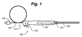
図1及び図2に例示されているように、本発明の一実施形態によるカテーテル及びハンドルシステム100は、細長いシャフト102及びシャフト102の第1又は遠位端部に結合されたアブレーションアセンブリ106を有するアブレーションカテーテルアセンブリ101、シャフト102の第2又は近位端部に結合された位置決めハンドルアセンブリ104、並びにカテーテルアセンブリ101及びハンドルアセンブリ104を送達装置、例えば、気管支鏡の作業チャネルに結合するための検査鏡結合アセンブリ103を含み得る。カテーテルアセンブリ101は、ハンドルアセンブリ104を介してシステムコンソール(不図示)にさらに流体的かつ電気的に結合され、冷却剤の供給及び戻りリザーバー、及びエネルギー供給部、例えば、RF発生器を備えている。ハンドルアセンブリ104は、処置を行う間にシャフト102の遠位部分又は端部、従って、アブレーションアセンブリ106を軸方向及び円周方向に操作するように構成されている。
(Detailed explanation)
As illustrated in FIGS. 1 and 2, a catheter and handle
図3に示されているように、本発明の非限定的な一実施形態では、アブレーションアセンブリ106は、1つ以上のエネルギー放射装置510、例えば、電極、及び拡張部材520、例えば、バルーン又はバスケットを含み得る。一部の実施形態では、アブレーションアセンブリ106は、電極510及び拡張部材520の表面を冷却して、電極510に接触した表面組織及び電極510に隣接した表面組織を保護するために冷却剤流路又は冷却回路600を含み得る。図4に示されているように、冷却回路600は、システムコンソールのリザーバー601から供給され、システムコンソールの任意の熱交換器603、ハンドル104、シャフト102の流入ルーメン、電極510が結合された導管540、拡張部材520、シャフト102の流出ルーメン、ハンドル104を経てシステムコンソールに戻る冷却剤を含む。システムコンソールの非限定的な例は、共に参照によりそれぞれの全内容が本明細書に組み入れられる、「冷却可能なエネルギー放出アセンブリを備えた送達装置(Delivery Devices with Coolable Energy Emitting Assemblies)」という名称の米国特許出願公開第2013/0289556号及び「気管支拡張のためのシステム及び方法(System and Method for Bronchial Dilation)」という名称の米国特許第8,489,192号で確認することができる。流体の循環は、例えば、蠕動ポンプ605によって達成される。代替の一実施形態では、冷却剤が電極の前に拡張部材を流れるように流れが逆転される。
As shown in FIG. 3, in one non-limiting embodiment of the invention,
再び図3を参照すると、アブレーションアセンブリ106は、導管540と拡張部材520との間の流れを制御するためのスロットル弁530を任意に含み得る。アブレーションアセンブリ106はまた、少なくともカテーテルシャフト102の長さに沿って、拡張部材520の近位端部520aの内部と遠位端部520bの内部との間に延びて、拡張部材520及びカテーテルシャフト102にさらなる軸方向の支持、捻じれ防止、及び座屈防止を提供する支持ワイヤ1214、例えば、ニチノールワイヤも任意に含み得る。より具体的には、支持ワイヤ1214の第1の部分又は端部1214aは、カテーテルシャフト102の遠位端部102aに結合され、第2の端部1214bは、スロットル弁530と拡張部材520との間の接合部で拡張部材520の遠位端部520bに結合されている。
Referring again to FIG. 3,
アブレーションアセンブリのさらなる詳細は、共に参照により上記それぞれの全内容が本明細書に組み入れられる、「気管支樹を処置するためのシステム、アセンブリ、及び方法(Systems, Assemblies, and Methods for Treating a Bronchial Tree)」という名称の米国特許第8,088,127号及び「冷却可能なエネルギー放射アセンブリを備えた送達装置(Delivery Devices with Coolable Energy Emitting Assemblies)」という名称の米国特許出願公開第2011/0152855号に記載されている。 Further details of the ablation assembly are provided in "Systems, Assemblies, and Methods for Treating a Bronchial Tree", the entire contents of each of which are incorporated herein by reference, together. U.S. Pat. No. 8,088,127 and "Delivery Devices with Coolable Energy Emitting Assemblies".
一部の実施形態では、図1及び図2を再び参照すると、ハンドルアセンブリ104は、張力緩和部材121によってハンドルアセンブリ104の端部に結合されたアンビリカルケーブル120を含み得、このアンビリカルケーブル120は、好ましくはシステムコンソールに組み込まれる付属器具又はアクセサリー、例えば、電源、エネルギー源、流体又は冷却剤供給部、熱交換機、及び制御装置にカテーテルアセンブリ101を流体的及び/又は電気的に結合する。アンビリカルケーブル120は、例えば、流入流体の冷却及び/又は加熱用の熱交換器を任意に含むコンソールの流体又は冷却剤供給部にシャフト102を流体結合させるための流入及び戻り流体チューブ又はルーメン105の接続部、並びにシャフト及び/若しくはアブレーションアセンブリを電源、温度監視用の熱電対、及び/又は冷却剤回路の圧力用の圧力センサに電気的に接続する1つ以上の電気ケーブル/コネクタ107を備えることができる。他の実施形態では、ハンドルアセンブリ104は、ハンドルアセンブリ104及び任意の付属器具又はアクセサリーを動作させるための内部バッテリー源を含み得る。
In some embodiments, referring again to FIGS. 1 and 2, the
図5を参照すると、カテーテルアセンブリ101及びハンドルアセンブリ104は、送達装置200、例えば、ガイドチューブ、送達シース、気管支鏡、又は内視鏡などに結合可能である。送達装置200は、1つ以上の視覚化装置、例えば、光学式視覚化装置(例えば、カメラ)、光学系(例えば、一連のレンズ)などを含み得る。特定の一実施形態では、送達装置200は、可撓性気管支鏡を備える。アブレーションアセンブリ(不図示)及び細長いシャフト102は、装置200の作業チャネルポート202に挿入される。次いで、ハンドルアセンブリ104が、検査鏡結合アセンブリ103を介して装置200に固定される。検査鏡結合アセンブリ103は、ハンドルアセンブリ104と一体若しくはハンドルアセンブリ104に結合しても良いし、又はそれ自体が、ハンドルアセンブリ104及びポート202の両方に結合するスタンドアロンアダプターであっても良い。検査鏡結合アセンブリ103は、例えば、摩擦若しくは当接嵌め(abutting fit)、ロッキングレバー、一致するねじ山の螺合、バヨネット若しくはスナップ嵌め、ばね荷重嵌め(spring loaded fit)、又は当業者に公知の任意の様々な機構によってポート202に確実に嵌められる。検査鏡結合アセンブリ103は、ハンドルアセンブリ104がポート202から不所望に外れるのを防止するロッキング機構208、例えば、レバー又はスライドロックをさらに含み得る。一旦固定されると、検査鏡結合アセンブリ103は、装置200に対して軸方向及び回転方向に固定される。次いで、事前に組み立てられていない場合は、ハンドルアセンブリ104は、より詳細に後述するように検査鏡結合アセンブリ103に固定される。
Referring to FIG. 5, the
ハンドルアセンブリ104の特定の一実施形態では、図6及び図7を参照すると、ハンドルアセンブリ104は、一般に、長手方向軸Aを有するハンドルアセンブリ104の内部空間を画定するハンドルハウジング又はカバー1002、及びハンドルフレーム、例えば、スピンドルチューブ1024を含む。一実施形態では、ハウジング1002は、第1のハンドルハウジング1002a及び第2のハンドルハウジング1002bを備え、該第2のハンドルハウジング1002bは、1つ以上のほぞ接合、対応する雄型及び雌型インターロッキング部品、ねじ、接着剤、溶接、又はハウジング接合のための任意の様々な機構によって第1のハンドルハウジング1002aに結合される。図示されていない他の実施形態では、ハウジングは、一体であるか、又は別法として3つ以上の部品から形成される。
In one particular embodiment of the
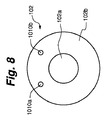
カテーテルアセンブリ101の細長いシャフト102の一部が、ハンドルハウジング1002内を長手方向軸Aに沿って延びている。カテーテルチューブ1004は、ハウジング1002内のシャフト102の鞘となり、該シャフト102を保護する。一実施形態では、図8を参照すると、カテーテルシャフト102は、システムコンソールの冷却剤供給部から新しい冷却剤又は循環冷却剤を、カテーテル102の遠位端部に結合されたアブレーションアセンブリ(例えば、図6に示されている)に供給するための中心冷却剤流入ルーメン102aを備える。冷却剤戻りルーメン102bは、該冷却剤戻りルーメン102bと冷却剤流入ルーメン102aが同軸となるように冷却剤流入ルーメン102aを取り囲んでいる。しかしながら、並列などの同軸でない他の配置も企図され得る。
A portion of the
図6を参照すると、近位端部のハンドルアセンブリ104のアンビリカルケーブルアセンブリ1006は、シャフト102の冷却剤流入ルーメン102a及び冷却剤戻りルーメン102bを冷却剤供給部及び戻りリザーバーに結合する。図1及び図2に関連して既に説明されたように、アンビリカルケーブルアセンブリ1006は、カテーテルシャフト102、そして最終的にアブレーションアセンブリ106を、好ましくはシステムコンソールに組み込まれた付属器具又はアクセサリー、例えば、電源、エネルギー源、流体若しくは冷却剤供給部、熱交換器、及び制御装置に流体的及び/又は電気的に結合するために、任意の様々なチューブ及び/又は電気ワイヤ若しくはケーブルをカテーテルチューブ1004及び/又はハンドルアセンブリ104に結合することができる。好ましくは、アンビリカルケーブルアセンブリ1006は、ゴム製の張力緩和部材121で終端する可撓性アンビリカルケーブル120を含む。
Referring to FIG. 6, the
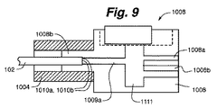
図9〜図12を参照すると、カテーテルチューブ1004とシャフト102の近位端部は、マニホールド1008を介してアンビリカルケーブルアセンブリ1006に動作可能に結合されている。マニホールド1008は、シャフト102とシステムコンソール(不図示)との間の流入、流出、及び/又は電気の流れを分配又は方向転換する。
With reference to FIGS. 9-12, the
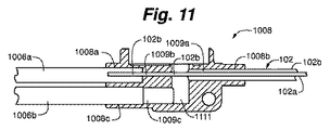
一実施形態では、図11及び図12を参照すると、マニホールド1008は、第1の流入ポート1008a及び第2の流入ポート1008bを備える。第1の流入ポート1008a及び第2の流入ポート1008bは、導管1009a及び1009b並びにゲート1111を介して互いに流体連通している。アンビリカルケーブルアセンブリ1006の冷却剤供給チューブ1006aの近位端部が、マニホールド1008の第1の部分1008aの内部に延び、接着結合、ヒートシール、超音波溶接、又は任意の様々な取り付け機構によって該第1の部分1008aの内面に固着されている。冷却剤供給チューブ1006aの遠位端部(不図示)は、システムコンソールの冷却剤供給部、任意の熱交換器、及びポンプに結合されている。
In one embodiment, referring to FIGS. 11 and 12, the
シャフト102の流入ルーメン102a及び流出ルーメン102bは、マニホールド1008の第2のポート1008b内に延び、かつ流出ルーメン102bは、接着結合、ヒートシール、超音波溶接、又は様々な取り付け機構のいずれかによってポート1008bの内面に固着されている。流入ルーメン102aは、シャフト102の流出ルーメン102bを越えて、導管1009a及び1009bを通って冷却剤供給チューブ1006aまで延びている。任意に、導管1009bの直径は、流入ルーメン102aを接着結合、ヒートシール、超音波溶接、又は様々な取り付け機構のいずれかによって導管1009bの内面に固着できるように、流入ルーメン102aの直径とほぼ同じである。
The
マニホールド1008は第3のポート1008cをさらに備える。アンビリカルケーブルアセンブリ1006の冷却剤戻りチューブ1006bの近位端部は、ポート1008c内に延びて、接着結合、ヒートシール、超音波溶接、又は様々な取り付け機構のいずれかによって第3のポート1008cの内面に固着されている。第3のポート1008cは、ゲート1111によって分離された導管1009c及び1009aを介して第2のポート1008b、従って該第2のポート1008bに固定された流出ルーメン102bに流体連通している。冷却剤戻りチューブ1006bの遠位端部(不図示)は、冷却剤の循環及び/又は廃棄のためにシステムコンソールのリザーバーに結合されている。
The manifold 1008 further includes a
使用の際は、冷却剤が、システムコンソールの冷却剤供給部から、アンビリカルケーブルアセンブリ1006の冷却剤供給チューブ1006aを介して供給される。次いで、冷却剤は、冷却剤供給チューブ1006aからカテーテルシャフト102の流入ルーメン102aの中に流れる。冷却剤は、後述するように、シャフト102の長さに沿ってアブレーションアセンブリ106の中に流れる。冷却剤は、アブレーションアセンブリ106を介して流出ルーメン102bの中に入り、シャフト102の長さに沿ってマニホールド導管1009a、リザーバー1111、そして導管1009cに入って循環する。冷却剤は、再循環及び/又は廃棄のために、冷却剤戻りチューブ1006bを介してマニホールド1008から流出してシステムコンソールに戻る。
In use, coolant is supplied from the coolant supply section of the system console via the
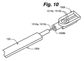
図9及び図10を再び参照すると、カテーテルチューブ1004は、マニホールド1008の第2のポート1008aの外面に固着され、従って第2のポート1008a、及びハンドルアセンブリ100に沿って該ハンドルアセンブリ内に延びたシャフト102の部分を覆っている。カテーテルチューブ1004は、接着結合、ヒートシール、超音波溶接、又は様々な取り付け機構のいずれかによってマニホールド1008に固定されている。
Referring again to FIGS. 9 and 10, the
図9、図11、及び図12を参照すると、マニホールド1008は、例えば、はんだ付け又は追加の直接プリントによって1つ以上のプリント回路基板を受容して固定するための、該マニホールド1008の表面に形成された凹状台座1113、並びにカテーテルアセンブリ101及び/又はアブレーションアセンブリ106の様々な位置における圧力、冷却剤の流入量及び流出流量、及び/又は温度を検出し、かつ任意に表示するための1つ以上の液体圧力センサ及び圧力計、流量センサ及び流量計、及び/又は熱電対をさらに備え得る。さらに、圧力センサ、流量センサ、及び/又は熱電対からのリード線が、台座1113をゲート1111に流体結合する、マニホールド1008の台座1113に形成された開口1115を通っている。リード線は、シャフト102を貫通して、最終的にアブレーションアセンブリ106に達している。一実施形態では、図8を再び参照すると、第1のリード線1010a及び第2のリード線1010bが、シャフト102の流出ルーメン102bを通ってアブレーションアセンブリ106まで延びている。
Referring to FIGS. 9, 11 and 12, a
マニホールド1008は、第1及び/又は第2のハンドルカバー1002a、1002bの内部に固定結合され、これによりマニホールド1008、従ってカテーテルチューブ1004がカバー1002に対して軸方向及び回転方向に固定されている。マニホールド1008は、例えば、図12に示されているように、ハウジング1002a又は1002bの内部に形成されたペグの、マニホールド1008に形成された対応するスリーブ1117への挿入によってハンドルカバー1002a及び/又は1002bに固定することができる。しかしながら、様々な取り付け機構のいずれかも企図され得る。
The manifold 1008 is fixedly coupled to the inside of the first and/or second handle covers 1002a, 1002b, whereby the
熱電対は、アブレーションアセンブリ106のエネルギー放射装置又は電極部位を含むカテーテルアセンブリ101内、冷却部材内の冷却剤の温度を測定するための該アブレーションアセンブリの該冷却部材内、並びに/又は流入及び/若しくは流出冷却剤の流れの温度を測定する際には細長いシャフト102内の流入及び/若しくは流出ルーメン102a、102b内の任意の場所に配置することができる。次いで、冷却剤の温度及び/又は冷却剤の流れが、アブレーション部位が十分に加熱されて表面組織が永久的な損傷を確実に受けるようにすると共に、電極及び冷却部材に接触している表面組織が十分に冷却されて標的組織の永久的な損傷が確実に回避又は防止されるように、システムコンソールにおいて手動又は自動で制御される。
Thermocouples are included in the
圧力及び/又は流量は、流入及び/又は流出ルーメン内で、並びに/又はアブレーションアセンブリの理論上の圧力及び/若しくは直圧を測定する際には冷却部材及び/若しくはアブレーションアセンブリ内で測定することができる。流入ルーメン内の圧力は、アブレーションアセンブリ内に配置されたスロットルにより、流出ルーメン内の圧力と比較して高くなり得る。特定の一実施形態では、アブレーションアセンブリの拡張部材、例えば、バルーンの圧力は、気道に望ましくない損傷を引き起こし得る気道内でのバルーンの過剰な拡張又は過剰なサイズを防止するために所定の圧力未満に維持される。流入ルーメン、スロットル、又は流出ルーメンが詰まった場合には、圧力センサ、例えば、ハンドルに配置された圧力センサが、対応するラインの圧力の上昇を検出して、拡張冷却部材が破裂又はバルーンが過剰に拡張しないように冷却剤ポンプを自動的に停止させ、かつ/又は処置部位が過剰に加熱されないように電極のエネルギー源を自動的に停止させる。代替の一実施形態では、圧力上昇を所定又は使用者設定の圧力限度に軽減するために圧力緩和弁をシステム内に組み入れることができる。特定の圧力測定アセンブリが以下により詳細に説明される。 The pressure and/or flow rate may be measured in the inflow and/or outflow lumens and/or in the cooling member and/or the ablation assembly when measuring the theoretical and/or direct pressure of the ablation assembly. it can. The pressure in the inflow lumen may be high compared to the pressure in the outflow lumen due to the throttle located in the ablation assembly. In one particular embodiment, the pressure of the expansion member of the ablation assembly, eg, the balloon, is less than a predetermined pressure to prevent over-expansion or over-sizing of the balloon within the airway that can cause unwanted damage to the airway. Maintained at. If the inflow lumen, throttle, or outflow lumen becomes clogged, a pressure sensor, for example, a pressure sensor located on the handle, detects an increase in pressure in the corresponding line, causing the expansion cooling member to burst or the balloon to become excessive. The coolant pump is automatically turned off to prevent expansion and/or the electrode energy source is turned off so that the treatment site is not overheated. In an alternative embodiment, a pressure relief valve may be incorporated into the system to reduce the pressure rise to a predetermined or user set pressure limit. Specific pressure measurement assemblies are described in more detail below.
一実施形態では、図13を参照すると、圧力センサ1200が、ハンドルアセンブリ1202又はその近傍に配置され、該圧力センサ1200は、カテーテルシャフト1203の流出ルーメン1204の圧力を測定するように構成されている。この実施形態は、アブレーションアセンブリ1206の下流(即ち、流出ルーメン1204)の圧力測定に基づいており、従って、理論圧力を相殺してアブレーションアセンブリ1206の拡張部材1208内の圧力を推定する必要がある。この実施形態では、拡張部材1208内の圧力は、該拡張部材1208に対するカテーテルシャフト1203内の流動抵抗により、計測器1200の圧力よりも高いと推定される。
In one embodiment, referring to FIG. 13, a
本発明のさらに別の実施形態では、拡張部材1208の過剰な膨張又は破裂を引き起こし得る、圧力センサ1200と該拡張部材1208との間の未検出の障害物又は閉塞を排除又は軽減するために、バルーン又はアブレーションアセンブリ1206内の圧力の直接測定が望ましい。図14を参照すると、圧力センサ1200が、ハンドルアセンブリ1202又はその近傍に配置されている。ポリマーチューブ及び/又は金属チューブ1210が、カテーテルシャフト1203の流出ルーメン1204に沿って配置されている。チューブ1210の第1の端部1210aは、圧力センサ1200に動作可能に結合され、第2の端部1210bは、アブレーションアセンブリ1206内で終端している。チューブ1210は、アブレーションアセンブリ1206内で圧力を直接測定するための静止カラムとして機能する;即ち、チューブ1210内のカテーテルシャフト1203を通る圧力が一定であるため、圧力センサ1200で測定される圧力が、アブレーションアセンブリ1206内の圧力に等しい。
In yet another embodiment of the present invention, to eliminate or mitigate undetected obstacles or occlusions between the
この実施形態では、チューブ1210は、可撓性でも良いし、又は剛性でも良い。図示されているように、支持ワイヤ1214、例えば、ニチノールワイヤが、拡張部材1208の内部の近位端部と遠位端部との間に延在し、拡張部材1208にさらなる軸方向の支持、捻じれ防止、及び座屈防止を提供する。より具体的には、支持ワイヤ1214の第1の端部1214aは、カテーテルシャフト1203の遠位端部1203aに結合され、第2の端部1214bは、スロットル弁1209と拡張部材1208との間の接合部において拡張部材1208の遠位端部に結合されている。この実施形態では、チューブ1210は、支持ワイヤ1214を補完することができる。
In this embodiment, the
さらに別の実施形態では、図15を参照すると、圧力チューブ1220が、前の実施形態の支持ワイヤの代わりをしている。この実施形態では、チューブ1220は、第1の端部1220aで、ハンドルアセンブリ1202又はその近傍に配置された圧力センサ1200に結合されている。チューブ1220の遠位部分1222は、拡張部材1208の近位端部と遠位端部との間に延在する。より具体的には、遠位部分1222の近位端部1222aは、カテーテルシャフト1203の遠位端部1203aに結合され、遠位部分1222の遠位端部1222bは、スロットル弁1209と拡張部材1208との間の接合部において拡張部材1208の遠位端部に結合されている。チューブ1220の遠位部分1222は、チューブ1220の長手方向軸に対し垂直に配置された1つ以上の開口1224を備える。前の実施形態と同様に、チューブ1210は、アブレーションアセンブリ1206内で圧力を直接測定するための静止カラムとして機能する;即ち、チューブ1210内のカテーテルシャフト1203を通る圧力が一定であるため、圧力センサ1200で測定される圧力が、アブレーションアセンブリ1206内の圧力に等しい。さらに、チューブ1220は、カテーテルシャフト1203及び拡張部材1208の全長に亘って軸方向の支持、捻じれ防止、及び座屈防止を提供し、これにより、より細くてより可撓性の高い流体保持チューブ(例えば、流入ルーメン及び流出ルーメン)が可能となる。
In yet another embodiment, referring to FIG. 15,
自動的に停止するシステム応答と組み合わせられた、システム内の圧力、流量、及び/又は温度のリアルタイム測定を含むプロセス制御ループが、不所望の組織又は気道の傷害を防止するための安全機構を提供する。 Process control loop, including real-time measurement of pressure, flow, and/or temperature in the system, combined with an automatically shut-down system response, provides a safety mechanism to prevent unwanted tissue or airway injury To do.
図6及び図7を再び参照すると、ハンドルアセンブリ104は、気管支鏡位置決めアセンブリ1012によって気管支鏡の作業チャネルに取り外し可能にさらに固定結合されている。一実施形態では、位置決めアセンブリ1012は、一方の回転方向のみで作業チャネルに取り付けできるように成形された検査鏡カップラー1014を含む。検査鏡カップラー1014は、ばね荷重ジョーレバー1016、ジョー戻りばね(圧縮ばね)1018、スライディングジョー1020、固定ジョー1022、及び該固定ジョー1022又は該カップラー1014に任意に結合されるシリコーンシール1023を介して気管支鏡(又は後述する気管支鏡アダプターアセンブリ)に結合される。レバー1016に加えられる力がばね1018に達し、これによりスライディングジョー1020及びジョー1022が、作業チャネルの凹部とのロック係合が解除され、検査鏡カップラー1014がこれらから解放される。
Referring again to FIGS. 6 and 7, the
スピンドルチューブ1024が、第1の端部1024aで、回転方向及び軸方向の両方向において検査鏡カップラー1014に固定結合されている。より具体的には、スピンドルチューブ1024のフランジ又はスカート1026が、検査鏡カップラー1014の平面1028に当接する。検査鏡カップラー1014の突出部1030は、ほぞ穴とほぞの方式でスピンドルチューブ1024の開口1032内に延在する。タブ1034は、突出部1030の一部にカチッと嵌り、検査鏡カップラー1014をスピンドルチューブ1024にロックする。スピンドルカバー1036が、ハンドルカバー1002に結合され、これによりスピンドルチューブ1024が、スピンドルカバー1036を介してその長さに沿って軸方向にスライド可能である。
A
スピンドルチューブ1024は、軸方向の微調整のために、スピンドルチューブ1024に対する長手方向軸Aに沿ったハンドルハウジング1002、従ってマニホールド1008及びカテーテルシャフト102の軸方向の移動により、ハンドルハウジング1002の内外に軸方向に伸長可能である。より具体的には、スピンドルチューブ1024は、カテーテルチューブ1004、従ってシャフト102の外径よりも大きい内径を有し、これにより、カテーテルチューブ1004及びシャフト102が、スピンドルチューブ1024の内外に軸方向に伸縮して、アブレーションアセンブリ106の軸方向の調整を達成する。シャフト102のスピンドルチューブ1024に対する移動距離は、アブレーションアセンブリ106の気管支鏡の作業端部又は先端部に対する所望の移動距離に基づいて選択される。一実施形態では、ハンドルハウジング1002が、検査鏡カップラー1014から離れるように軸方向に延びると、ハウジング1002に固定されたマニホールド1008も離れる方向に延び、シャフト102が該マニホールド1008と共に引っ張られ、これにより、該シャフト102の遠位部分に結合されたアブレーションアセンブリ106が気管支鏡に向かって、任意に完全に又は部分的に引き戻され、検査鏡カップラー1014に向かう軸方向の移動の場合は逆の動きとなる。
The
ハンドルハウジング1002及びカテーテルチューブ1004、従ってシャフト102は、スピンドルチューブ1024から完全に引き離されるのを防止している。より具体的には、スピンドルチューブ1024の第2の端部1024bが、スピンドル保持アセンブリ1040によってハウジング1002内に軸方向に保持される。スピンドル保持アセンブリ1040は、スピンドルチューブ1024の端部に固定されたスピンドルエンドキャップ1042、及びU字型のピンによってスピンドルエンドキャップ1042に結合されるハンドルストップ1044を含む。ハンドルハウジング1002が検査鏡カップラー1014から軸方向に延びて完全に伸長すると、ハンドルストップ1044の半径方向突出部が、ハンドルハウジング1002の内面から突き出た半径方向に延びた機能構造に当接し、これによりさらなる軸方向の伸長が防止される。同様に、ハウジング1002の長手方向の長さに沿ったハンドルハウジング1002の内面の機能構造が、スピンドルエンドキャップ1042がスピンドルチューブ1024と共に回転するときに、ハンドルストップ1044の外面の半径方向に延びたと突出部に当接してハンドルストップ1044がハウジング1002内で回転するのを防止する。
The
ハンドルストップ1044は、ノッチをさらに備え、該ノッチは、完全に引き戻された又は閉じた構造でマニホールド1008に隣接すると該マニホールド1008に取り外し可能に係合して、所望に応じてスピンドルチューブ1024をマニホールド1008及びハウジング1002に対する軸方向の移動をロックする。
The
アブレーションアセンブリ106の気管支鏡の作業端部又は先端部に対する所望の軸方向の移動距離は、カテーテルアセンブリ101のシャフト102の全長、及びカテーテルチューブ1004のハンドルアセンブリ104のスピンドルチューブ1024に対する関係によって設定又は決定される。一実施形態では、アブレーションアセンブリ106の気管支鏡の作業端部又は先端部に対する所望の移動距離は、アブレーションアセンブリ106の全長と同等以上である。一実施形態では、アブレーションアセンブリ106の長手方向の長さは、図7に示されているように、導管/電極に加えて拡張部材(例えば、バルーン)の長さを含み;代替の一実施形態では、アブレーションアセンブリ106の長手方向の長さは、拡張部材のみの長さを含む。単純にするために、アブレーションアセンブリ106の長手方向の長さが一般に参照され、該アブレーションアセンブリ106は、いずれかの長さを含み得る。
The desired axial travel of the
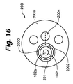
この関係を実証するために、非限定的な一実施形態では、作業チャネルの(ハンドルアセンブリを結合可能な)近位開口から遠位作業端部又は先端部(図16を参照)までの測定される市販の気管支鏡の作業長さは、約40〜約80cm、より詳細には約50〜約65cm、さらに詳細には約55〜約60cmである。ハンドルアセンブリ101のハウジング1002内に延びたシャフト102の部分は、約15〜約20cmの長さとすることができる。ハウジング1002内の部分及び気管支鏡を貫通して延在する長さを含む(ただし、アブレーションアセンブリ106の長さを含まない)カテーテルアセンブリ101のシャフト102の全長は、約55〜100cm、より詳細には約65〜約85cm、さらに詳細には約70〜80cmである。これにより確実に、シャフト102が、ハンドルハウジング1002を貫通して延出し、ハンドルアセンブリ104が気管支鏡に結合されると該気管支鏡を貫通して延出することができる。特定の一実施形態では、シャフト102は、アブレーションアセンブリ106が結合されたシャフト102の遠位部分が気管支鏡の作業端部又は先端部を越えて伸長可能で、シャフト102の約0.1cm〜約4cmが該気管支鏡の遠位側に露出するように、追加の長さを含む。
To demonstrate this relationship, in one non-limiting embodiment, the measurement from the proximal opening (to which the handle assembly can be coupled) of the working channel to the distal working end or tip (see FIG. 16) is performed. The working length of commercially available bronchoscopes is about 40 to about 80 cm, more specifically about 50 to about 65 cm, and more specifically about 55 to about 60 cm. The portion of
さらに、この実施形態では、アブレーションアセンブリ106は、約1〜約8cm、より詳細には約3〜約5cm、さらに詳細には約4cmの長手方向の長さを有するバルーン又はバスケットを含む。スピンドルチューブ1024が検査鏡カップラー1014に結合されると、ハンドルハウジング1002は、カテーテルチューブ1004、従ってシャフト102の一部が、アブレーションアセンブリ106の長手方向の長さと同等以上の長さ、ハンドルアセンブリ104のスピンドルチューブ1024内を伸縮する、又は該スピンドルチューブ1024に対して軸方向に移動するように選択される距離、軸方向に移動することができる。これにより、アブレーションアセンブリ106は、気管支鏡の作業端部又は先端部(シャフト102の全長によって、作業端部の外側の間隙を有する又は有さない)から完全に延出した状態と、該気管支鏡の作業端部(シャフト102の全長によって、作業端部の内側の間隙を有する又は有さない)内に完全に引き込まれた状態との間で変化可能となる。
Further, in this embodiment,
例えば、シャフト102の全長は、ハンドルアセンブリ104が気管支鏡に結合されて、完全に閉じるか又は収縮する(例えば、カテーテルチューブ1004が、本明細書では「完全に閉じたハンドル構造」と呼ばれるスピンドル1024内の最大引き込み位置にある)と、アブレーションアセンブリ106のバルーンの近位肩が約0.1〜約4.0cm、より詳細には約2cm、該気管支鏡の作業端部を越えて延びるように選択することができる。ハンドルアセンブリ104が、ハウジング1002が検査鏡結合アセンブリ103から軸方向の最大距離にある「完全に延出したハンドル構造」にあると、アブレーションアセンブリ106全体が作業端部内に引き込まれて、気道を遮るものがない視覚化が可能となる。この実施形態では、移動距離は、バルーンの長さよりも長く、例えば、この移動距離は、約1cm+0.1〜4.0cmから約8.0cm+0.1〜4.0cmなどである。気管支鏡の視覚化装置とバルーンとの間の光学的結合が、バルーンの近位肩が該気管支鏡の作業端部に当接するハンドルアセンブリ106の部分的な軸方向の延出(即ち、「部分的に延出したハンドル構造」)で起こる。
For example, the entire length of the
代替の一実施形態では、ハンドルアセンブリ104が完全に閉じたハンドル構造になると、アブレーションアセンブリ106のバルーンの近位肩が、気管支鏡の作業端部に当接して、該気管支鏡の作業端部に配置された視覚化装置に光学的に結合される。カテーテルチューブ1004、従ってシャフト102は、ハンドルアセンブリ104が完全に軸方向に延出して完全に延出したハンドル構造になったときにバルーン全体が気管支鏡の作業端部内に引き込まれるように、少なくともバルーンの長さに等しい距離、スピンドルチューブ1024に対して軸方向に移動する。
In an alternative embodiment, when the
別の代替の実施形態では、ハンドルアセンブリ104が完全に延出したハンドル構造になると、アブレーションアセンブリ106のバルーンの近位肩が、気管支鏡の作業端部に当接して、該気管支鏡の作業端部に位置する視覚化装置に光学的に結合される。この実施形態では、アブレーションアセンブリ106は気管支鏡内に引き込まれない。
In another alternative embodiment, when the
特定の一態様では、ハンドルハウジング1002の移動距離、従ってアブレーションアセンブリ106の移動距離は、シャフト102の全長の約1〜約20%、より詳細にはシャフト102の全長の約1〜約10%である。好ましい実施形態では、ハンドルハウジング1002のスピンドルチューブ1024に対する移動距離、従ってアブレーションアセンブリ106のスピンドルチューブ1024に対する移動距離は、少なくともアブレーションアセンブリ106の長さ、好ましくはアブレーションアセンブリ106の長さの少なくとも約105%、より好ましくはアブレーションアセンブリ106の長さの少なくとも約110%である。
In one particular aspect, the travel of the
特定の一態様では、ハンドルアセンブリ104のスピンドルチューブ1026、カテーテルチューブ1004、又は他の構成要素は、アブレーションアセンブリ106が気管支鏡内に完全に引き込まれたとき、及び/又はその他の様々な所望の位置にあるときに、該アブレーションアセンブリのバルーンが該気管支鏡の作業端部に物理的に当接すると視覚化装置と該アブレーションアセンブリとの光学的結合を表示するために視覚的及び/又は触覚的応答を提供する表示ノッチ又はタブマーキング、センサ、照明装置、又は他の適切な装置を所定位置(複数可)に備え得る。
In one particular aspect, the spindle tube 1026,
ハンドルハウジング1002、従ってマニホールド1008、カテーテルチューブ1004、及びカテーテルシャフト102はまた、処置領域内でのアブレーションアセンブリの円周方向の微調整のために、ハンドルハウジング1002の気管支鏡及び検査鏡カップラー1014に対する回転によってスピンドルチューブ1024に対して回転可能である。1つ以上の軸受1038a、1038bが、ハンドルハウジング1002のスピンドルチューブ1024を中心とするスムーズな回転を促進するためにハンドルハウジング1004の内面に摩擦固定される。ハンドルストップ1044がハウジング1002と共にスピンドルチューブ1024及びスピンドルエンドキャップ1042を中心に回転するため、ハンドルストップ1044及び/又はスピンドルチューブ1024は、任意に、回転量に対応する触覚表示又は「クリック」を提供する刻み目を備え得る。例えば、1クリックは、中立位置から1度以上の回転に対応させることができる。
The
背景の部分で説明されたように、気管支鏡及びカテーテルアセンブリが回転するときに撮影される画像が正しい向きに維持されるように、気管支鏡の光ファイバーカメラ部分が、気管支鏡に対して固定されている。これは、処置部位、例えば、気道内でのアブレーションアセンブリの実際の向きを分からなくする可能性がある。ここで図16及び図17A〜図17Cを参照すると、一実施形態では、シャフト102の遠位端部2000は、処置部位内でのアブレーションアセンブリ106の向きを表示するための1つ以上のマーカー2002を備え得る。一実施形態では、マーカー2002は、遠位端部2000の外側の少なくとも一部に沿って長手方向に延在する長手方向のストライプ又はバンド、例えば、黒色パッドプリントバンドを備える。検査鏡結合アセンブリ103及びハンドルアセンブリ104が気管支鏡に結合されると、カテーテルアセンブリ101の細長いシャフト102が、作業チャネル201及び検査鏡200を経て、図16に示されているように検査鏡200の作業端部200aで該作業チャネル201から延出する。ハンドルアセンブリは、唯一の向きで作業チャネル201のみに結合させることができるため、細長いシャフト102が、既知又は最初の向きで作業チャネル201を貫通して該作業チャネル201から延出する。この実施形態では、細長いシャフト102は、マーカー2002がカメラ2004の中心に整合するよう、気管支鏡を貫通して延在するようにハンドルアセンブリに結合される。
As described in the background section, the fiber optic camera portion of the bronchoscope is fixed relative to the bronchoscope so that the images taken as the bronchoscope and catheter assembly rotate are maintained in the correct orientation. There is. This can obscure the actual orientation of the ablation assembly within the treatment site, eg, the respiratory tract. 16 and 17A-17C, in one embodiment, the
任意に、放射線不透過性マーカー(不図示)を、アブレーションアセンブリの向きをX線撮影、蛍光透視、超音波、又は他の迅速な確認スキャン(confirmation scan)によって観察できるように、アブレーションアセンブリ、例えば、電極の近傍又は電極上にプリント又は他の方法で堆積させることができる。 Optionally, a radiopaque marker (not shown) may be used to allow the orientation of the ablation assembly to be viewed by radiography, fluoroscopy, ultrasound, or other rapid confirmation scan, eg, , Can be printed or otherwise deposited near or on the electrodes.
バンド2002は、アブレーションアセンブリの気管支鏡の作業端部に対する軸方向の向きでも役立ち得る。例えば、一旦アブレーションアセンブリが気道で拡張されると、アブレーションアセンブリを、バンドがカメラで観察できなくなるまで引き戻して気管支鏡に近づけることができる。これは、アブレーションアセンブリの光学的結合が達成されるようなバルーン又は拡張部材とカメラとの間の最適な距離を示す。これにより、アブレーションアセンブリの電極を気管支鏡の作業端部から観察することが可能となる。さらに、カメラは、アブレーションアセンブリと独立に移動させることができる。
編組2006を、シャフト102の遠位端部2000の少なくとも一部に沿って配設することができる。編組2006は、遠位端部2000に捩じり安定性を付与するため、ハンドルアセンブリ104のハウジング1002及びマニホールド1008の操作によりシャフト102の全長が移動し、これによりアブレーションアセンブリ106が、ハンドル及び/又は気管支鏡の動きに応答して直接回転し軸方向に移動する。編組2006はまた、シャフト102が捻じれるのを防止又は抑制する。上記のように、光学的結合を妨げないように、非編組部分2008の小さい間隙を遠位端部2000の端部に設けることもできる。
The
再び図5A〜図5Cを参照されたい。一旦装置200に係合すると、使用者は、アブレーションアセンブリ106を備えたカテーテルアセンブリ101を、処置が行われる空洞部又は管腔、例えば、気道で操作することができる。アブレーションアセンブリ106の粗調整は、ハンドルアセンブリ104、従ってマニホールド1008及びカテーテルチューブ1006が検査鏡結合アセンブリ103及び装置200と共に移動してアブレーションアセンブリ106を軸方向に移動及び/又は回転させるような装置200の軸方向及び回転方向の運動によって行われる。
Please refer to FIG. 5A to FIG. 5C again. Once engaged in the
アブレーションアセンブリ106の微調整は、図5A〜図5Cに示されているように、ハンドルハウジング1002の装置200及び検査鏡結合アセンブリ103に対する軸方向及び回転方向の運動(220及び230)によって達成される。例えば、ハウジング1002を、送達装置200に対する軸方向の引き込み位置(図5B)に移動させることにより、カテーテルチューブ1004が、スピンドルチューブ1024内に進入して、アブレーションアセンブリ106を備えたシャフト102の遠位端部が、装置200の遠位部分に対して最大に延出して、処置が行われる空洞部、管腔、又は脈管内に入る。これにより、例えば、使用者が、処置のために広範囲の組織を標的にすることが可能となる。カテーテルチューブ1004がスピンドルチューブ1024から引き戻されるハンドルハウジング1002の延出(図5A)により、シャフト102の遠位端部、従ってアブレーションアセンブリ106が、装置200の遠位部分に向かって引き戻され、場合によっては、装置200の作業端部内に引き戻される。
Fine adjustment of the
一部の実施形態では、図5Cを参照すると、ハンドルハウジング1002は、シャフト102及び/又はアブレーションアセンブリ106の円周方向又は回転方向の位置を調整するための制御部又は操作機構として機能する。例えば、ハンドルハウジング1002、従ってマニホールド1008及びカテーテルチューブ1006は、検査鏡カップラー1014及び装置200に対して所定の増分で、又は連続的に回転するように構成することができる。様々な回転目盛のいずれかを、例えば、1度、5度、10度、20度、30度、45度、90度、120度、又は180度の増分で視覚的及び/又は触覚的に(例えば、クリックで)ハンドル104に組み入れることができる。
In some embodiments, referring to FIG. 5C, handle
代替の一実施形態では、図18に示されているように、ハンドルアセンブリ304は、検査鏡カップラー303に固定されたスピンドルチューブ305を中心に回転するように構成された本体部分310を含む、円周方向/回転方向の操作のための制御機構を備え、該本体部分310が一円周方向に回転すると、装置200、作業チャネルポート202、及び検査鏡カップラー303が固定された状態で、カテーテルシャフト及びアブレーションアセンブリが同じ円周方向に回転する。他の実施形態では、本体部分310は同様に、スピンドルチューブ305及び検査鏡カップラー303に対して軸方向に移動するように構成され、本体部分310が一軸方向に移動すると、カテーテルシャフト及びアブレーションアセンブリが、装置200及び検査鏡カップラー303に対して同じ軸方向に移動する。
In an alternative embodiment, as shown in FIG. 18, the
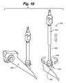
代替の一実施形態では、図19に示されているように、ハンドルアセンブリ402は、軸方向の操作用の第1の本体部分404及び回転操作用の第2の本体部分406を含む。ハンドルアセンブリ402は、検査鏡アダプター403を介して検査鏡200の作業チャネル部分202に結合されている。アダプター403は、ポート202に対して軸方向及び回転方向の両方向に固定されている。スピンドルチューブ405は、アダプター403に軸方向に固定されている。ハンドルアセンブリ402は、スピンドルチューブに沿って軸方向に移動するように構成された第1の本体部分404を含み得、この軸方向の移動は、カテーテルシャフトの遠位端部に固定されたアブレーションアセンブリの軸方向の運動に変換される。第2の本体部分406、スピンドルチューブ405、及び第1の本体部分404は、検査鏡アダプター403を中心として回転するように構成され、この回転は、アブレーションアセンブリの回転運動に変換される。
In an alternative embodiment, as shown in FIG. 19, the
さらに他の実施形態(不図示)では、軸方向及び円周方向の運動の制御部は、ハンドルの機構を手動で操作しなくても、内視鏡器具の遠位部分を操作できるように構成された、1つ以上のモーター、液圧若しくは空気圧シリンダー、又は関連するボタン、スイッチ、センサなどを備えた他の動力マニピュレーターを備え得る。さらに他の実施形態(不図示)では、正確又は微細な軸方向及び/又は回転方向の調整のための制御機構が、例えば、サーボモーターによって自動化される。 In yet another embodiment (not shown), the axial and circumferential motion controls are configured to allow manipulation of the distal portion of the endoscopic instrument without manually manipulating the handle mechanism. Can be equipped with one or more motors, hydraulic or pneumatic cylinders, or other power manipulators with associated buttons, switches, sensors, etc. In yet another embodiment (not shown), the control mechanism for precise or fine axial and/or rotational adjustment is automated, for example by a servomotor.
カテーテル位置決めハンドルアセンブリ及びシステムは、気管支鏡又は他の送達装置、及び該送達装置に結合された付属品、例えば、カメラ及び/又は光源から独立した、カテーテルシャフト及びアブレーションアセンブリの微調整及び操作を可能にする。例えば、ハンドルを使用して、気管支鏡に関連したカメラ又は他の光学素子で可視化してアブレーションアセンブリをより正確に配置することができ、該気管支鏡を介してカテーテルが配置される。好ましくは、ハンドルは、処置中にアブレーションアセンブリを光学素子で視認できるようにカテーテルの操作を容易にする。好ましい実施形態では、ハンドルは、カテーテルアセンブリの拡張部材と気管支鏡の光学素子との光学的結合を容易にし、位置決めの視覚的な手掛かりとなる二次情報源は、処置中にこのような光学的結合を維持するためにエネルギー放射装置が気管支鏡に対して適切となる位置へのカテーテルの固定を示す、アブレーションアセンブリ上の放射線不透過性マーカー又は放射線不透過性表示装置の形態にすることができる。 A catheter positioning handle assembly and system allows for fine tuning and manipulation of a catheter shaft and ablation assembly independent of a bronchoscope or other delivery device and accessories associated with the delivery device, eg, camera and/or light source. To For example, the handle can be used to visualize a camera or other optical element associated with the bronchoscope to more accurately position the ablation assembly through which the catheter is placed. Preferably, the handle facilitates manipulation of the catheter so that the ablation assembly is visible with optics during the procedure. In a preferred embodiment, the handle facilitates the optical coupling between the expansion member of the catheter assembly and the optics of the bronchoscope, and the secondary source of visual cues for positioning is such optical cues during the procedure. It can be in the form of a radiopaque marker or radiopaque indicator on the ablation assembly that shows the anchoring of the catheter in a position where the energy emitting device is appropriate to the bronchoscope to maintain the bond. ..
非限定的な実施形態によると、使用の際は、肺疾患の処置(例えば、標的肺除神経処置)中、気管支鏡を、典型的な気管支鏡処置手順に従って気道に配置することができる。使用者は、右又は左の主気管支を選択することができる。1つ以上の電極が結合されたバルーンを含むカテーテルアセンブリは、カテーテルのシャフトの遠位端部に対して折り畳む、収縮させる、又は巻き付けることができる。シャフト及びアブレーションアセンブリが、気管支鏡の作業チャネルに挿入され、ハンドルアセンブリと検査鏡アダプターが、該ハンドルアセンブリが該気管支鏡に固定されるように接続される。次いで、カテーテルシャフトが、カテーテルシャフトの遠位端部のバンドによって整合され、これにより使用者が、この最初の位置決めによって電極の気道に対する位置及び向きが分かる。一部の実施形態では、シャフトのマーキングは、気管支鏡から見ることができ、電極の位置決めの間に使用者に役立ち得る。任意に、放射線不透過性マーカーを、追加の位置確認用として組み込むことができる。 According to a non-limiting embodiment, in use, a bronchoscope can be placed in the airway according to typical bronchoscopic procedure during treatment of lung disease (eg, targeted pulmonary denervation procedure). The user can select the right or left main bronchus. A catheter assembly that includes a balloon with one or more electrodes attached can be folded, deflated, or wrapped against the distal end of the catheter shaft. The shaft and ablation assembly are inserted into the working channel of the bronchoscope and the handle assembly and spectroscopic adapter are connected so that the handle assembly is secured to the bronchoscope. The catheter shaft is then aligned by the band at the distal end of the catheter shaft, which allows the user to know the position and orientation of the electrode relative to the airway by this initial positioning. In some embodiments, the markings on the shaft may be visible through the bronchoscope and may assist the user during electrode positioning. Radiopaque markers can optionally be incorporated for additional localization.
使用者は、カテーテルシャフト及びアブレーションアセンブリを気道(例えば、右又は左の気管支)内に配置することができる。粗調整は、ハンドルが検査鏡と共に移動するため、気管支鏡自体の軸方向及び回転方向の移動によって行われる。微調整は、シャフト及びアブレーションアセンブリを検査鏡に対して調整して(即ち、検査鏡を移動させることなく)電極を処置に有利な位置に配置するハンドルの軸方向及び円周方向の制御部を用いる処置(例えば、無線周波数療法を用いる肺除神経)のために気道で行われる。例えば、一旦、気道の軟骨輪間に配置されると、使用者はバルーンを膨張させることができ、これにより電極(複数可)が気道壁に接触することになる。 The user can place the catheter shaft and ablation assembly in the airway (eg, right or left bronchus). Coarse adjustment is performed by axial and rotational movement of the bronchoscope itself as the handle moves with the examination mirror. Fine tuning involves adjusting the shaft and ablation assembly relative to the speculum (ie, without moving the speculum) to position the electrodes in a treatment-friendly position for axial and circumferential control of the handle. Performed in the respiratory tract for the procedure used (eg, pulmonary denervation using radio frequency therapy). For example, once placed between the cartilage rings of the airway, the user can inflate the balloon, which causes the electrode(s) to contact the airway wall.
気道内での電極及びバルーンの位置は、気道の解剖学的構造及び他の装置に対する電極及びバルーンの位置の視覚的な手掛かりを提供する、気管支鏡に結合されたカメラ、例えば、光ファイバー及び/又は電荷結合素子(CCD)チップを備えたレンズを用いて知らせることができる。電極及びバルーンの視覚化は、該電極及びバルーンとは独立にカメラを移動させて行うことができる。例えば、使用者は、固定されたカテーテルアセンブリのハンドルを保持し、次いで、電極及びバルーンの位置をずらすことなく該電極及びバルーンに向かってカメラを軸方向に移動させる。ハンドルを静止位置に維持することができるため、カテーテルアセンブリの電極及びバルーンが気道の固定位置に維持され、従って使用者が、様々な視野を得るためにカメラを軸方向及び円周方向に自由に移動させることができる。一旦所望の位置に達すると、使用者は、1つ以上の電極に電力供給すると同時に、上記のように冷却剤を冷却回路を循環させることによって処置を行うことができる。 The position of the electrodes and balloon within the airway provides a visual clue to the position of the electrodes and balloon relative to the airway anatomy and other devices, such as a camera coupled to a bronchoscope, such as an optical fiber and/or A lens with a charge coupled device (CCD) chip can be used for signaling. Visualization of the electrode and the balloon can be performed by moving the camera independently of the electrode and the balloon. For example, the user holds the handle of the fixed catheter assembly and then moves the camera axially toward the electrode and balloon without shifting the position of the electrode and balloon. Since the handle can be maintained in a rest position, the electrodes of the catheter assembly and the balloon are maintained in a fixed position in the airway, thus allowing the user to freely move the camera axially and circumferentially to obtain different views. Can be moved. Once the desired location is reached, the user can perform the procedure by energizing one or more electrodes while simultaneously circulating a coolant through the cooling circuit as described above.
一部の実施形態では、円周傷が望ましく、かつ電極のサイズが気道の周囲よりも小さい場合には、処置が繰り返される。例えば、最初のエネルギーの供給後に、使用者は、例えば、冷却剤の流れを停止又は遅くしてバルーン及び電極を備えた任意の導管を減圧することによって、少なくとも部分的又は完全にバルーンを収縮させる。次いで、使用者は、気管支鏡(粗調整)、そしてハンドルの制御機構(微調整)を回転及び/又は移動させ、これにより電極を移動させて組織の最初の四分円から回転及び/又は軸方向に離れた異なる四分円に電極を再配置することができる。一部の実施形態では、気管支鏡の位置を移動させることなく、ハンドルを用いるアブレーションの前に、電極を軸方向及び円周方向の一方又は両方でより細かく調整することができる。 In some embodiments, the procedure is repeated if a circumferential wound is desired and the electrode size is smaller than the circumference of the airway. For example, after the initial application of energy, the user at least partially or fully deflates the balloon, for example by stopping or slowing the flow of coolant to depressurize any conduit with the balloon and electrodes. .. The user then rotates and/or moves the bronchoscope (coarse adjustment) and the handle control mechanism (fine adjustment), thereby moving the electrodes to rotate and/or rotate from the first quadrant of the tissue. The electrodes can be rearranged in different quadrants that are separated in direction. In some embodiments, the electrodes may be more finely tuned in one or both axially and circumferentially prior to ablation with the handle without moving the position of the bronchoscope.
電極が主気管支の周囲の4分の1である特定の一実施形態では、気管支鏡を介して挿入されるときの電極の最初の位置は腹側である。例えば、左主気管支内に配置される場合は、電極が左側四分円にくるように、ハンドルアセンブリ及び気管支鏡が反時計回りに90度回転させられる。必要に応じて、上記のように軸方向及び/又は回転方向の微調整を電極に対して行うことができる。黒色バンドが依然としてカメラの中心にあるかのカメラでの確認、及び他の任意の確認が行われる。アブレーションアセンブリが上記のように加圧され、エネルギーが電極に供給されて標的組織がアブレーションされる。処置の完了時に、バルーンが少なくとも部分的に減圧され、電極が腹側四分円にくるように、気管支鏡及びハンドルアセンブリが共に時計回りに90度回転させられる。処置が上記のように繰り返される。次いで、気管支鏡及びハンドルアセンブリが、右側まで時計回りに90度回転させられ、処置が繰り返される。最後に、気管支鏡及びハンドルアセンブリが、背側四分円まで時計回りに90度回転させられ、処置が繰り返される。次いで、カテーテルアセンブリを気管支鏡内に引き戻すことができ、必要に応じて、該気管支鏡を右主気管支内に配置することができ、治療が繰り返される。この時計回りの処置により、実施者が、気管支鏡及びアブレーションアセンブリを気道の周囲に沿って片手で容易に回転させることが可能となる。 In a particular embodiment where the electrode is a quarter of the circumference of the main bronchus, the initial position of the electrode when inserted through the bronchoscope is the ventral side. For example, if placed in the left main bronchus, the handle assembly and bronchoscope are rotated 90 degrees counterclockwise so that the electrode is in the left quadrant. If necessary, the electrodes can be finely adjusted in the axial direction and/or the rotational direction as described above. A camera check is made to see if the black band is still in the center of the camera, and any other check. The ablation assembly is pressurized as described above and energy is delivered to the electrodes to ablate the target tissue. At the completion of the procedure, the balloon is at least partially decompressed and both the bronchoscope and handle assembly are rotated 90 degrees clockwise so that the electrodes are in the ventral quadrant. The procedure is repeated as above. The bronchoscope and handle assembly is then rotated 90 degrees clockwise to the right and the procedure is repeated. Finally, the bronchoscope and handle assembly is rotated 90 degrees clockwise to the dorsal quadrant and the procedure is repeated. The catheter assembly can then be withdrawn back into the bronchoscope, if desired the bronchoscope can be placed into the right main bronchus and the treatment repeated. This clockwise procedure allows the practitioner to easily rotate the bronchoscope and ablation assembly around the airway with one hand.
一部の実施形態では、処置条件として、例えば、領域又は気管支鏡先端部を清掃するために、気管支鏡の吸引動作を使用する必要があり得る。このような実施形態では、ハンドルが完全に延出した位置(例えば、図5Aを参照)にくるように該ハンドルを引っ張って、カテーテルシャフト及びアブレーションアセンブリの遠位部分全体を気管支鏡の作業チャネル内に引き込むことができる。次いで、真空装置又は吸引ルーメンを気管支鏡の作業チャネルを介して、該気管支鏡の位置をずらすことなくデブリを吸引する位置に延出させることができる。 In some embodiments, the treatment condition may require the use of a suction action of the bronchoscope, for example, to clean the area or bronchoscope tip. In such an embodiment, the handle is pulled so that it is in the fully extended position (see, eg, FIG. 5A), and the entire distal portion of the catheter shaft and ablation assembly is within the working channel of the bronchoscope. Can be pulled into. A vacuum device or suction lumen can then be extended through the working channel of the bronchoscope to a position for aspirating debris without shifting the position of the bronchoscope.
処置が完了したら、使用者は、ハンドル100を気管支鏡から分離することなく、該ハンドルをその完全に延出した位置(例えば、図5Aを参照)まで該ハンドルを引っ張って、カテーテルのシャフト及びアブレーションアセンブリ全体を該気管支鏡の作業チャネル内に引き込むことができる。これにより、カテーテルを気管支鏡カメラの視界に入らないようにすることができ、例えば、処置の有効性の評価が容易になる。次いで、使用者は、気管支鏡を処置のための他方の気管支に向きを合わせることができ、そしてカテーテルシャフト及びアブレーションアセンブリを気管支鏡の作業チャネルから他方の気管支内に進めることができる。
Once the procedure is complete, the user pulls the
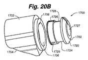
ここで図20A〜図20Fを参照すると、気管支鏡アダプターアセンブリの一実施形態が示されている。アダプターアセンブリ1700は、既に説明されたように装置200の作業チャネルポート202に対するカテーテルアセンブリのハンドルアセンブリの結合を容易にするように構成されており、作業チャネルは、カップラーアセンブリ103を収容するためのポートとは異なるサイズであるか、又は該ポートよりも小さい。アダプターアセンブリ1700は、一般に、シュラウド1702及びカップラー1720を含む。シュラウド(又はシェル)1702は、ハウジング部1704、貫通孔1706、及び任意の整合タブ1708を備える。カップラー1720は、フランジ1722、首部1724、カラー部1726、貫通孔1727、整合スロット1728、1つ以上の任意の部分リリーフスロット1729、及びカップラー1720の内面にあるレッジ1730を備える。フランジ1722は、ハンドル104のアダプターアセンブリ1700へのより容易な接続が可能となるように、図20A〜図20Fに示されているようにテーパ面を備え得る。
20A-20F, one embodiment of a bronchoscope adapter assembly is shown. The
図20Dに示されているように、フランジ1722は、内径D1及び外径D2を有する。図20Cに示されているように、首部1724は、首部1724とフランジ1722との間の接合部に当接レッジ1723が形成されるようにフランジ1722の内径D1よりも大きい内径D3を有する。当接レッジ1723は、ポート202の端部で当接する関係で保持フランジF1と協働し得る。
As shown in FIG. 20D, the
カラー部1726は、首部1724とカラー部1726との間の接合部に当接レッジ1730が形成されるように内径D3よりも大きい可変内径D4を有する。当接レッジ1730は、図20Cに示されているように、ポート202の端部において当接関係で保持フランジF2と協働し得る。
The
図20Bに示されているように、カラー1726は、アダプターアセンブリ1700とポート202との係合及び/又は係合解除の際に起こり得る拡張及び/又は収縮を容易にするための1つ以上の通しリリーフスロット(1728)及び/又は部分リリーフスロット(1729)を備え得る。
As shown in FIG.20B,
図20C及び図20Fに示されているように、カップラー1720は、ポート202の外周又は直径の周りに装着され、ハンドル104の結合アセンブリ103の大きい接触面を効果的に形成している。カップラー1720のスロット1728が、シュラウド1702のタブ1708を受容するように構成されている。アダプターアセンブリ1700を装置200のポート202に装着する際には、図20Eに示されているように、孔1706がカップラー1720の首部1724に近接して配置され、そして、例えば、D4が支持直径(resting diameter)であり、カラー部1726が拘束されないようにシュラウド1702が最初に配置される。次いで、アダプターアセンブリ1700をポート202に対して前進させることができ、このときにカラー部1726が自由に拡張して(従ってD4が自由に拡張して)、レッジ1730がポート202の第1の保持フランジF1を通過して第2の保持フランジF2に当接するのを可能にする。次いで、シュラウド1702を、図20Fに示されているように、シュラウド1702の孔1706がカップラー1720のカラー部1726に整合するロック位置に移動させることができ、これによりカラー部1726が締め付けられてD4が最小化して、該カラー部1726がポート202の周りに確実に適合する。この結果、アダプターアセンブリ1700がポート202に係合し、カテーテルアセンブリ101のハンドルアセンブリ104を、アダプターアセンブリ103を介してカップラー1720のフランジ1722に接続することができる。
As shown in FIGS. 20C and 20F, the
任意に、スロット1728は、カラー部1726に向かって広くなり、かつフランジ部1722に向かって狭くなるテーパ形状を備えることができる。スロット1728のこのようなテーパ構造により、シュラウド1702が、カップラー1720のフランジ1722に向かってカラー部1726から前進すると、アダプターアセンブリ1700がポート202から係合解除されるため、シュラウド1702のタブ1708が狭いスロット1728内を前進してカラー部1726が広がり、これによりリッジ1730が、ポート202の保持フランジを解放し、アダプターアセンブリ1700をポート202から除去されるという点で、アダプターアセンブリ1700のポート202との容易な係合及び/又は係合解除が促進される。
Optionally, the
アダプターアセンブリ1700の寸法は、様々な送達装置200に結合させるために、所望に応じて選択することができる。
The dimensions of the
代替の一実施形態では、シュラウドは、整合タブ(不図示)を備えず、図20Dに示されている代替のカップラー1800が可能であり、該カップラー1800は、通しスロットを備えない代わりに、アダプターアセンブリ1700とポート202との係合及び/又は係合解除の間に生じ得る拡張及び/又は収縮を容易にする複数の部分リリーフスロット1802を備えるように構成されている。
In an alternative embodiment, the shroud does not include alignment tabs (not shown) and allows the alternative coupler 1800 shown in FIG.20D, which instead of having a through slot, provides an adapter. It is configured with a plurality of
実施形態では、キット150は、上記のカテーテルアセンブリ101及びハンドルアセンブリ104、並びに、例えば、図21に示されている150の内容物を使用するための一連の使用説明書152を含み得る。キット150は、結合アセンブリ103及び/又はアダプターアセンブリ1700も含んでも良いし、又はアダプターアセンブリ103及び/又はアダプターアセンブリ1700をキット150とは別に提供しても良い。キット150は、1つ以上の密封され滅菌されたパッケージから構成することができる。キット150の内容物は、必要に応じて既に組み立てられた状態で提供しても良いし、又は内容物を個別に提供しても良く、使用説明書152は、本明細書に記載される内容物を連結するステップを含む。キット150及び/又はキット150の個々の内容物は、該キット及び/又は内容物を製造させることで使用者に利用可能にすることによって提供しても良い。
In an embodiment, the
使用説明書152は、限定されるものではないが、書面の説明書、CD、又はCD-ROM、CD、CD-ROM、DVD、ブルーレイを含む任意の様々な有形又は無形の表現媒体であり得、個人用機器、例えば、コンピューター、タブレット、スマート機器にデジタルダウンロード可能又はこれらで視聴可能であり、かつ/又はキット150の供給者による口頭の説明によるものであり得る。別の実施形態では、本明細書に記載の様々な実施形態に従ってアセンブリを使用するための説明書152は、例えば、アセンブリを提供することとは別にアセンブリの製造者又は供給者によって、例えば、インターネットを用いてアクセス可能な情報によって、又はセミナー、講義、若しくは講習会などによって提供される。
Instructions for
従って、本発明の実施形態により、使用者が、気管支鏡とは独立にカテーテルシャフト及びアブレーションアセンブリを操作して、効率的かつ効果的な処置を促進する位置に容易かつ便利に到達させることができ、最終的に患者の転帰が改善され、回復時間が短縮される。さらに、気管支鏡に結合されたハンドルアセンブリは、気管支鏡の視覚化装置又はカメラによって提供される視覚的な手掛かりを補完する、処置部位内のアブレーションアセンブリのポインター又はインジケーターとなる。最後に、気管支鏡に結合されたハンドルアセンブリは、気管支鏡視覚化装置のアブレーションアセンブリへの容易かつ効率的な視覚的又は光学的結合を可能にする。 Thus, embodiments of the present invention allow a user to manipulate the catheter shaft and ablation assembly independently of the bronchoscope to easily and conveniently reach a position that facilitates efficient and effective treatment. , Ultimately improving patient outcomes and reducing recovery time. In addition, the handle assembly coupled to the bronchoscope provides a pointer or indicator to the ablation assembly within the treatment site that complements the visual cues provided by the bronchoscope visualization or camera. Lastly, the handle assembly coupled to the bronchoscope allows easy and efficient visual or optical coupling of the bronchoscope visualization device to the ablation assembly.
実施形態によるハンドル及びカテーテルシステムは、上記の拡張部材及び1つ以上のエネルギー放射装置又は電極を備えるアブレーションアセンブリを操作するために使用することができ、かつ/又は、例えば、肺障害の処置用の神経毒、硬化剤、様々な薬剤のいずれかの注入又は送達のための針注射及び/若しくは無針注射又は薬物送達システムを含む様々な処置アセンブリのいずれかの軸方向、回転方向、及び/又は他の操作のために設計又は構成することができる。例えば、ハンドル及びカテーテルシステムは、1つ以上の針又はポートを気道の内部及び周りで軸方向(前進及び後退)及び/又は回転方向に操作するように構成することができる。アセンブリの様々な非限定的な例は、以下に列記される1つ以上の特許及び特許出願に記載され、これらの特許及び特許出願は全て、参照によりそれぞれの全内容が本明細書又は上記に組み入れられる:
「気管支樹を処置するためのシステム、アセンブリ、及び方法(Systems, Assemblies, and Method for Treating a Bronchial Tree)」という名称の米国特許第8,088,127号;
「冷却可能なエネルギー放射アセンブリを備えた送達装置(Delivery Devices with Coolable Energy Emitting Assemblies)」という名称の米国特許出願公開第2011/0152955号;
「組織を処置し、狭窄を制御するためのシステム、器具、及び方法(Systems, Apparatus, and Methods for Treating Tissue and Controlling Stenosis)」という名称の米国特許出願公開第2012/0310233号;
「除神経を行うための非侵襲性及び低侵襲性除神経の方法及びシステム(Non-invasive and Minimally Invasive Denervation Methods and Systems for Performing the Same)」という名称の米国特許出願公開第2011/0118725号;
「対象をスクリーニングするための方法及びシステム(Methods and Systems for Screening Subjects)」という名称の米国特許出願公開第2012/0302909号;
「肺の処置のためのシステム及び方法(System and Method for Pulmonary Treatment)」という名称の米国特許出願公開第2011/0301587号;
「神経毒を用いて喘息を処置するための器具(Apparatus for Treating Asthma Using a Neurotoxin)」という名称の米国特許第8,172,827号;
「少なくとも1つの気道の狭窄を制御するための方法及び装置(Method and Apparatus for Controlling Narrowing of at Least One Airway)」という名称の米国特許出願公開第号;
「気管支拡張のためのシステム及び方法(System and Method for Bronchial Dilation)」という名称の米国特許第8,483,831号;
「神経組織を傷害させるための器具及び方法(Apparatuses and Methods for Injuring Nerve Tissue)」という名称の国際公開第2013/052501号;
「肺機能を改善させるための小型の肺処置実施システム及び方法(Compact Delivery Pulmonary Treatment System and Method for Improving Pulmonary Function)」という名称の米国特許出願公開第2013/0310822号;
「薬効を改善するための方法(Methods for Improving Drug Efficacy)」という名称の米国仮特許出願第61/746,460号;
「処置のための流体送達システム及び方法(Fluid Delivery System and Method for Treatment)」という名称の米国仮特許出願第61/779,371号;
「超音波エネルギーで肺疾患を処置するためのシステム、装置、及び方法(Systems, Devices, and Methods for Treating a Pulmonary Disease with Ultrasound Energy)」という名称の米国仮特許出願第61/876,925号;
「肺の処置手順中に食道を保護するための方法(Methods for Protecting the Esophagus During Pulmonary Treatment Procedures)」という名称の米国仮特許出願第61/847,477号;及び
共に「薬剤で肺障害を処置するためのシステム、装置、及び方法(Systems, Devices, and Methods for Treating a Pulmonary Disorder with an Agent)」という名称の米国仮特許出願第61/799,742号及び同第61/870,373号。
The handle and catheter system according to embodiments can be used to manipulate an ablation assembly that includes the expansion member and one or more energy emitting devices or electrodes described above, and/or, for example, for the treatment of lung disorders. Axial, rotational, and/or any of a variety of treatment assemblies including neurotoxins, sclerosants, needle injections and/or needle-free injections or drug delivery systems for infusion or delivery of any of various agents. It can be designed or configured for other operations. For example, the handle and catheter system can be configured to manipulate one or more needles or ports axially (advancing and retracting) and/or rotationally within and around the airway. Various non-limiting examples of assemblies are described in one or more patents and patent applications listed below, all of which are hereby incorporated by reference in their entireties herein or above. Incorporated:
US Patent No. 8,088,127 entitled "Systems, Assemblies, and Method for Treating a Bronchial Tree";
US Patent Application Publication No. 2011/0152955 entitled "Delivery Devices with Coolable Energy Emitting Assemblies";
U.S. Patent Application Publication No. 2012/0310233 entitled "Systems, Apparatus, and Methods for Treating Tissue and Controlling Stenosis";
U.S. Patent Application Publication No. 2011/0118725 entitled "Non-invasive and Minimally Invasive Denervation Methods and Systems for Performing the Same";
US Patent Application Publication No. 2012/0302909 entitled "Methods and Systems for Screening Subjects";
US Patent Application Publication No. 2011/0301587 entitled "System and Method for Pulmonary Treatment";
US Pat. No. 8,172,827 entitled “Apparatus for Treating Asthma Using a Neurotoxin”;
U.S. Patent Application Publication No. "Method and Apparatus for Controlling Narrowing of at Least One Airway";
US Patent No. 8,483,831 entitled "System and Method for Bronchial Dilation";
WO 2013/052501 entitled "Apparatuses and Methods for Injuring Nerve Tissue";
U.S. Patent Application Publication No. 2013/0310822, entitled "Compact Delivery Pulmonary Treatment System and Method for Improving Pulmonary Function".
US Provisional Patent Application No. 61/746,460 entitled "Methods for Improving Drug Efficacy";
US Provisional Patent Application No. 61/779,371 entitled "Fluid Delivery System and Method for Treatment";
U.S. Provisional Patent Application No. 61/876,925 entitled "Systems, Devices, and Methods for Treating a Pulmonary Disease with Ultrasound Energy";
U.S. Provisional Patent Application No. 61/847,477 entitled "Methods for Protecting the Esophagus During Pulmonary Treatment Procedures"; and both "To treat lung disorders with drugs. US Provisional Patent Application Nos. 61/799,742 and 61/870,373 entitled "Systems, Devices, and Methods for Treating a Pulmonary Disorder with an Agent".
また、1又は複数の例示的な実施形態は単なる例であり、いかなる場合も本発明の主題の範囲、適用性、又は構成を限定することを意図するものではないことを理解されたい。むしろ、上記の詳細な説明は、1又は複数の例示的な実施形態の実施に役立つ開示を当業者に提供する。添付の特許請求の範囲及びその法的等価物に記載される本発明の主題の範囲から逸脱することなく、要素の機能及び構成を様々に変更できることを理解されたい。 Also, it is to be understood that the one or more exemplary embodiments are merely examples and are not intended to limit the scope, applicability, or configuration of the subject matter of the invention in any way. Rather, the foregoing detailed description will provide those skilled in the art with a disclosure that will be useful in implementing one or more exemplary embodiments. It is to be understood that various changes may be made in the function and arrangement of elements without departing from the scope of the inventive subject matter described in the appended claims and their legal equivalents.
上記の実施形態は、例示目的であり、限定するものではない。追加の実施形態は特許請求の範囲内である。特定の実施形態を参照して本主題を説明してきたが、当業者であれば、本発明の主題の精神及び範囲から逸脱することなく、形態及び細部を変更できることを理解されよう。 The above embodiments are for purposes of illustration and not limitation. Additional embodiments are within the claims. Although the present subject matter has been described with reference to particular embodiments, those skilled in the art will recognize that changes can be made in form and detail without departing from the spirit and scope of the subject matter of the invention.
当業者であれば、本開示を読めば、本発明の主題の様々な改良が明らかであろう。例えば、関連分野の一般的な技術者であれば、主題の様々な実施形態で述べられた様々な特徴は、本発明の主題の精神の範囲内で、他の特徴と適切に組み合わせる、組み合わせない、及び再び組み合わせても良いし、単独でも良いし、又は異なる組み合わせでも良いことを理解されよう。同様に、上記の様々な特徴は全て、本発明の主題の範囲又は精神の限定ではなく、実施形態の例と見なすべきである。従って、上記は、本発明のこの主題の範囲を限定することを企図するものではない。 Various modifications of the present subject matter will be apparent to those of ordinary skill in the art upon reading this disclosure. For example, one of ordinary skill in the relevant art will appreciate that various features described in various embodiments of the subject matter can be appropriately combined or not combined with other features within the spirit of the subject matter of the invention. , And may be recombined, alone, or in different combinations. Similarly, all of the various features described above are to be considered as example embodiments rather than limitations on the scope or spirit of the subject matter of the invention. Therefore, the above is not intended to limit the scope of this subject matter of the present invention.
本主題の請求項の理解を目的として、「〜の手段」又は「〜のステップ」という特定の語が特許請求の範囲で記載されない限り、米国特許法第112条の第6段落の規定が行使されないことを明確に意図する。
本件出願は、以下の構成の発明を提供する。
(構成1)
送達装置に結合するためのカテーテル及びハンドルアセンブリであって、該送達装置が、近位作業ポート、遠位作業端部、及び該作業ポートと該作業端部との間に延在し、作業長さを画定する作業チャネルを備え、該アセンブリが:
カテーテルアセンブリであって、
細長いシャフト、
該細長いシャフトの第1の端部に結合された、エネルギー放射装置を備えるアブレーションアセンブリを含む、該カテーテルアセンブリ;
該細長いシャフトの第2の端部に結合されたハンドルアセンブリであって、
ハンドルフレーム及び制御部を備え、該制御部が、該ハンドルフレームに対して移動可能であり、かつ該制御部の移動により、該アブレーションアセンブリが該ハンドルフレームに対して軸方向及び円周方向の少なくとも一方に移動するように、該細長いシャフトに結合されている、該ハンドルアセンブリ;及び
該ハンドルアセンブリ及び該送達装置の該作業ポートに結合するように構成された結合アセンブリであって、該制御部が移動して該アブレーションアセンブリを移動させる間に、該送達装置及び該ハンドルフレームに対する固定を維持するように構成され、該ハンドルアセンブリが該結合アセンブリを介して該送達装置に動作可能に結合されると、該細長いシャフトの第1の部分が、該送達装置の該作業チャネル内部に、及び通過して延在する、該結合アセンブリを含む、前記アセンブリ。
(構成2)
前記制御部が移動すると、前記細長いシャフト及び前記アブレーションアセンブリの両方が前記送達装置に対して移動する、構成1記載のアセンブリ。
(構成3)
前記結合アセンブリが、前記ハンドルアセンブリを前記送達装置の前記ポートに固定するためのカップラー及びロック機構を含む、構成1〜2のいずれか一項記載のアセンブリ。
(構成4)
前記制御部が、前記アブレーションアセンブリの前記送達装置に対する軸方向及び円周方向の操作用に構成されている、構成1記載のアセンブリ。
(構成5)
前記制御部が、前記ハンドルフレームの長手方向軸を中心に円周方向に回転して前記アブレーションアセンブリを円周方向に回転させるように構成された本体を備える、構成1〜4のいずれか一項記載のアセンブリ。
(構成6)
前記本体が、一円周方向に回転すると、前記アブレーションアセンブリが同じ円周方向に回転する、構成5記載のアセンブリ。
(構成7)
前記本体が、前記ハンドルフレームに回転可能に結合されたハンドルハウジングを備える、構成5記載のアセンブリ。
(構成8)
前記制御部が、軸方向の操作のために前記ハンドルの長手方向軸に沿って軸方向に移動するように構成された本体を備える、構成1〜7のいずれか一項記載のアセンブリ。
(構成9)
軸方向の操作用の前記制御部が、前記ハンドルの前記長手方向軸に沿って軸方向に移動するように構成された本体を備え、該本体が一軸方向に移動すると、前記シャフト及び前記アブレーションアセンブリが同じ軸方向に移動する、構成8記載のアセンブリ。
(構成10)
前記制御部が、前記ハンドルフレームに対して閉じた又は引き込まれた状態と延出した状態との間で変化可能であり、該制御部の変化により、前記アブレーションアセンブリが、前記ハンドルフレームに対して軸方向に移動するように、該制御部が前記細長いシャフトに結合され、かつ
前記カテーテルアセンブリの前記細長いシャフトが、前記制御部が前記引き込まれた状態及び前記延出した状態の一方にあるときに前記送達装置の前記作業長さと同等以上のカテーテル呼び長さを有する、構成1〜9のいずれか一項記載のアセンブリ。
(構成11)
前記カテーテル呼び長さが、前記送達装置の前記作業端部に結合された又は前記作業端部と一体の視覚化装置との前記アブレーションアセンブリの光学的結合を可能にする、構成10記載のアセンブリ。
(構成12)
前記制御部が、前記アブレーションアセンブリの少なくとも一部が前記作業チャネル内に引き込まれるように少なくとも部分的に延出した状態に変化可能である、構成10記載のアセンブリ。
(構成13)
前記アブレーションアセンブリの全体が、前記制御部が前記延出した状態にあるときに前記作業チャネル内に引き込まれる、構成12記載のアセンブリ。
(構成14)
前記アブレーションアセンブリが、前記制御部が引き込まれた状態にあるときに、前記送達装置の前記作業端部から約0.1〜約4.0cmの距離を延出する、構成10記載のアセンブリ。
(構成15)
前記制御部が前記引き込まれた状態と前記延出した状態との間で変化するときの前記アブレーションアセンブリの全移動距離が、該アブレーションアセンブリの長手方向の長さと同等以上である、構成10記載のアセンブリ。
(構成16)
前記アブレーションアセンブリの前記全移動距離が、前記カテーテル呼び長さの約1%〜約20%である、構成15記載のアセンブリ。
(構成17)
前記アブレーションアセンブリの前記全移動距離が、前記カテーテル呼び長さの約1%〜約10%である、構成16記載のアセンブリ。
(構成18)
前記ハンドルが、電源コードへの接続用のコネクタをさらに備える、構成1〜17のいずれか一項記載のアセンブリ。
(構成19)
前記ハンドルが、電源として内部バッテリーをさらに備える、構成1〜18のいずれか一項記載のアセンブリ。
(構成20)
前記ハンドルが、流体源に接続するための流体接合部をさらに備える、構成1〜19のいずれか一項記載のアセンブリ。
(構成21)
前記細長いシャフトの前記第1の端部が、蛍光透視で視認できる表示装置を備え、該表示装置が、前記アブレーションアセンブリの前記送達装置に対する整合を示す、構成1〜20のいずれか一項記載のアセンブリ。
(構成22)
前記表示装置が、前記細長いシャフトの前記第1の端部の外面に沿った細長いストライプを備え、バンドが前記細長いシャフトに対して実質的に平行である、構成15記載のアセンブリ。
(構成23)
前記アブレーションアセンブリが、蛍光透視視覚化下で該アブレーションアセンブリの前記送達装置に対する位置を示す放射線不透過性マーカーを含む、構成1〜22のいずれか一項記載のアセンブリ。
(構成24)
送達装置への結合用であり、該送達装置が気管支鏡を備える、構成1〜23のいずれか一項記載のアセンブリ。
(構成25)
前記アブレーションアセンブリが、第1の収縮状態と第2の拡張状態との間で移動可能な拡張部材をさらに含み、前記エネルギー放射装置が、該拡張部材の一部の上又は内部に配置される、構成1〜24のいずれか一項記載のアセンブリ。
(構成26)
前記アブレーションアセンブリが、前記エネルギー放射装置及び/又は前記拡張部材の表面を冷却するために、冷却剤が循環するための冷却剤流路を含む、構成25記載のアセンブリ。
(構成27)
前記カテーテルアセンブリが、カテーテルの第2の端部から前記細長いシャフトに沿って前記アブレーションアセンブリの前記拡張部材の中まで延びている圧力チューブを含み、該圧力チューブの第1の端部が、前記ハンドルアセンブリ上に又はその近傍に配置された圧力センサに動作可能に結合され、該圧力チューブの第2の端部が、該拡張部材内に配置され、かつ少なくとも1つの開口を備え、これにより該圧力センサが該拡張部材内の圧力を検出する、構成26記載のアセンブリ。
(構成28)
前記圧力チューブがニチノールから形成される、構成27記載のアセンブリ。
(構成29)
前記アセンブリを使用するための一連の使用説明書をさらに含み、該使用説明書が:
前記アブレーションアセンブリを送達装置のチャネルを介して気道内に配置すること;
前記結合アセンブリを該送達装置に固定すること;及び
該アブレーションアセンブリを該気道内の位置に軸方向及び円周方向に移動させて患者に肺処置を行うように該結合アセンブリが該送達装置に固定されたままで前記制御部を移動させること、を含む、構成1記載のアセンブリ。
(構成30)
構成1〜29のいずれか一項記載のカテーテル及びハンドルアセンブリを用いた肺処置の方法であって、前記アブレーションアセンブリを送達装置のチャネルを介して気道内に配置するステップ、前記結合アセンブリを該送達装置に固定するステップ、及び、該アブレーションアセンブリを該気道内の位置に軸方向及び円周方向に移動させて患者に肺処置を行うように該結合アセンブリが該送達装置に固定されたまま前記制御部を移動させるステップを含む、前記方法。
(構成31)
前記肺処置が、前記アブレーションアセンブリからエネルギーを送達して気道壁に沿って神経幹をアブレーションするステップを含む、構成30記載の方法。
(構成32)
前記アブレーションアセンブリからエネルギーを送達するステップが、該アブレーションアセンブリ内の圧力が所定の最大圧力を超えると中止される、構成31記載の方法。
(構成33)
前記アブレーションアセンブリが、前記送達装置とは独立に操作可能である、構成30記載の肺処置の方法。
(構成34)
肺処置の方法であって、カテーテルを送達装置を介して患者の気道内に導入するステップ、該カテーテルに結合されたハンドルアセンブリを該送達装置に固定するステップ、及び該ハンドルアセンブリの制御部を移動させて該カテーテルの遠位部分を気道内のある位置まで軸方向及び円周方向に操作して、患者に肺処置を行うステップを含み、該カテーテルの該遠位部分が、該送達装置に結合された可視化装置とは独立に操作可能であり、かつ該カテーテルの該遠位部分が、該遠位部分の表示が視覚化された状態で操作される、前記方法。
(構成35)
肺処置の方法であって:
カテーテルを送達装置を介して患者の気道内に導入するステップ;
該カテーテルに結合されたハンドルアセンブリを該送達装置に固定するステップ;
該ハンドルアセンブリの制御部を移動させて、該気道内の第1の円周位置まで該カテーテルの遠位部分を円周方向に操作するステップ;
該第1の円周位置で第1の処置を行うステップ;
該ハンドルアセンブリの該制御部を移動させて、該気道内の第2の円周位置まで該カテーテルの該遠位部分を円周方向に操作するステップ;及び
前記第2の円周位置で第2の処置を行うステップを含み;
該カテーテルの該遠位部分が該第1及び第2の円周位置に操作される間に、該ハンドルアセンブリが該送達装置に固定されたままである、前記方法。
(構成36)
前記カテーテルの遠位部分が前記第1及び第2の円周位置に操作されるときに、前記送達装置が前記気道に対して静止位置に維持される、構成35記載の方法。
(構成37)
前記第1の処置後及び前記第2の処置前に、前記ハンドルアセンブリが前記送達装置に固定されたまま前記制御部を移動させて、前記カテーテルの遠位部分を該送達装置内に引き込むステップをさらに含む、構成35記載の方法。
(構成38)
前記カテーテルの遠位部分が拡張部材を備え、該拡張部材の全長が前記送達装置内に引き込まれるように前記制御部が移動する、構成37記載の方法。
(構成39)
第1及び第2の処置が、前記カテーテルの遠位部分から前記気道の壁にエネルギーを送達して該壁に沿って神経幹をアブレーションするステップを含む、構成35記載の方法。
(構成40)
前記送達装置が光学チャネルを備え、前記方法が、前記カテーテルの遠位部分が前記第1及び第2の円周位置に操作されるときに、該遠位部分を該光学チャネルを介して観察するステップをさらに含む、構成35記載の方法。
(構成41)
前記カテーテルの遠位部分が、それに結合された拡張部材を有し、該拡張部材が、拡張した場合に前記光学チャネルに光学的に結合される所定の位置まで、前記制御部を移動させるステップをさらに含む、構成40記載の方法。
(構成42)
前記遠位部分を前記第1及び第2の円周位置に操作する間、前記カテーテルの遠位部分の表示を蛍光透視で視覚化するステップをさらに含む、構成35記載の方法。
(構成43)
前記第1の処置を行った後及び前記第2の処置を行う前に、前記ハンドルアセンブリが固定された前記送達装置を操作して、前記カテーテルの遠位部分を前記気道に対して回転方向に再配置するステップをさらに含む、構成35記載の方法。
(構成44)
構成1〜43のいずれか一項記載の肺処置の方法を行うためのキットであって:
カテーテルアセンブリであって、
細長いシャフト、
該細長いシャフトの第1の端部に結合された、エネルギー放射装置を備えるアブレーションアセンブリを含む、該カテーテルアセンブリ;
該細長いシャフトの第2の端部に結合されたハンドルアセンブリであって、
ハンドルフレーム及び制御部を含み、該制御部が、該ハンドルフレームに対して移動可能であり、かつ該制御部の移動により、該アブレーションアセンブリが該ハンドルフレームに対して軸方向及び円周方向の少なくとも一方に移動するように、該制御部が該細長いシャフトに結合されている、該ハンドルアセンブリ、
第1のカップラー及びロック装置を含む結合アセンブリであって、該ハンドルフレームを送達装置のポートに固定結合するように構成され、該アブレーションアセンブリが移動する間に該送達装置に対して固定されたままである、該結合アセンブリ;及び
構成1〜43のいずれか一項記載の肺処置の方法を行うための使用説明書、を含む、前記キット。
(構成45)
第2のカップラー及びシースを含むアダプターアセンブリをさらに含み、前記送達装置の前記ポートが、前記結合アセンブリの前記第1のカップラーが該ポートに直接結合されないように該第1のカップラーとは異なる大きさであり、該ポートが、該第2のカップラーの第1の端部が該ポートに結合可能であるように該第1の端部に実質的に等しい大きさであり、かつ該第2のカップラーの第2の端部が、該第2のカップラーの該第2の端部が該第1のカップラーに結合可能であるように該第1のカップラーに実質的に等しい大きさであり、これにより前記ハンドルアセンブリが該送達装置の該ポートに間接的に結合される、構成44記載のキット。
(構成46)
前記第2のカップラーが、前記第1の端部のフランジ、前記第2の端部のカラー部、及び該フランジと該カラーとの間に延在する首部を備え、前記第1のカップラーの端部を該フランジで受け止めるように構成され、該カラー部が前記ポートに適合するように構成されている、構成45記載のキット。
(構成47)
前記第2のカップラーの少なくとも前記カラーが、前記アダプターアセンブリの前記ポートとの係合及び/又は係合解除の際の前記カップラーの拡張及び/又は収縮を容易にするために1つ以上のリリーフスロットを備える、構成46記載のキット。
(構成48)
前記使用説明書が、書面の使用説明書、CD、CD-ROM、DVD、ブルーレイであり、かつ/又は個人用機器、例えば、コンピューター、タブレット、スマート機器にデジタルダウンロード可能又はこれらで視聴可能である、構成44〜47のいずれか一項記載のキット。
(構成49)
カテーテル及びハンドルアセンブリであって:
細長いシャフト;
該細長いシャフトの第1の端部に結合され、エネルギー放射装置を備えるアブレーションアセンブリ;
該細長いシャフトの第2の端部に固定されたハンドル;及び
該ハンドルに結合され、かつ送達装置のポートに結合可能な結合アセンブリを含み、該ハンドルの一部が、該結合アセンブリ及び該ポートに対して移動可能であり、該結合アセンブリが該送達装置に対して固定された状態で、該アブレーションアセンブリを該送達装置に対して軸方向及び円周方向の少なくとも一方に移動させる、前記カテーテル及びハンドルアセンブリ。
(構成50)
肺処置の方法であって、カテーテルを送達装置を介して患者の気道内に導入するステップ、該カテーテルに結合されたハンドルアセンブリを該送達装置に固定するステップ、及び該ハンドルアセンブリの制御部を移動させて該カテーテルの遠位部分を気道内のある位置まで軸方向及び円周方向に操作して、患者に肺処置を行うステップを含み、該カテーテルの該遠位部分が、該送達装置に結合された可視化装置とは独立に操作可能である、前記方法。
(構成51)
カテーテルアセンブリを使用者に提供するステップであって、該カテーテルが:
細長いシャフト;及び
該細長いシャフトの第1の端部に結合され、エネルギー放射装置を備えるアブレーションアセンブリを含む、該ステップ;
ハンドルアセンブリを該使用者に提供するステップであって、該ハンドルアセンブリが、該細長いシャフトの第2の端部に結合可能であり、該ハンドルアセンブリが:
ハンドルフレーム;及び
制御部であって、該ハンドルフレームに対して移動可能であり、該制御部の移動により、該ハンドルフレームに対して軸方向及び円周方向の少なくとも一方に該アブレーションアセンブリが移動するように該細長いシャフトに結合された、該制御部を含む、該ステップ;並びに
使用説明書を該使用者に提供するステップであって、該使用説明書が:
前記ハンドルアセンブリを送達装置のポートに固定すること;
該アブレーションアセンブリを患者の気道内の所望の位置に軸方向及び円周方向に移動させるように該ハンドルアセンブリの該制御部を操作すること;及び
該アブレーションアセンブリによって患者に肺処置を行うことを含む、該ステップを含む、方法。
(構成52)
結合アセンブリを前記使用者に提供するステップであって、該結合アセンブリが、前記ハンドルアセンブリと前記送達装置の前記ポートとを結合するように構成され、該結合アセンブリが、前記アブレーションアセンブリが移動する間に該送達装置に対する固定が維持されるように構成されている、該ステップをさらに含む、構成51記載の方法。
(構成53)
使用者にカテーテルアセンブリを提供するステップが、該カテーテルアセンブリを製造させ、該使用者に利用可能にするステップを含み、ハンドルアセンブリを該使用者に提供するステップが、該ハンドルアセンブリを製造させ、該使用者に利用可能にするステップを含む、構成51記載の方法。
For purposes of understanding the claims of the present subject matter, unless the specific words "means of" or "steps of" are set forth in the claims, the provisions of paragraph 6 of section 112 of the U.S.C. Not explicitly intended.
The present application provides the invention of the following configurations.
(Structure 1)
A catheter and handle assembly for coupling to a delivery device, the delivery device extending between a proximal working port, a distal working end, and the working port and the working end. With a working channel defining a height, the assembly comprising:
A catheter assembly,
Elongated shaft,
The catheter assembly including an ablation assembly comprising an energy emitting device coupled to a first end of the elongated shaft;
A handle assembly coupled to the second end of the elongated shaft,
A handle frame and a control unit, the control unit being movable relative to the handle frame, and the movement of the control unit causing the ablation assembly to be at least axially and circumferentially relative to the handle frame. The handle assembly coupled to the elongated shaft for movement in one direction; and
A coupling assembly configured to couple to the working port of the handle assembly and the delivery device, the fixation relative to the delivery device and the handle frame while the control moves to move the ablation assembly. And a first portion of the elongate shaft within the working channel of the delivery device when the handle assembly is operably coupled to the delivery device through the coupling assembly. And said coupling assembly extending therethrough.
(Configuration 2)
The assembly of configuration 1, wherein both the elongate shaft and the ablation assembly move relative to the delivery device when the control portion moves.
(Structure 3)
3. The assembly of any of configurations 1-2, wherein the coupling assembly includes a coupler and locking mechanism for securing the handle assembly to the port of the delivery device.
(Structure 4)
The assembly of Configuration 1, wherein the controller is configured for axial and circumferential manipulation of the ablation assembly with respect to the delivery device.
(Structure 5)
Any one of Configurations 1-4, wherein the controller comprises a body configured to rotate circumferentially about a longitudinal axis of the handle frame to rotate the ablation assembly circumferentially. Assembly as described.
(Structure 6)
6. The assembly of configuration 5, wherein when the body rotates in one circumferential direction, the ablation assembly rotates in the same circumferential direction.
(Structure 7)
6. The assembly of configuration 5, wherein the body comprises a handle housing rotatably coupled to the handle frame.
(Structure 8)
8. The assembly of any one of configurations 1-7, wherein the controller comprises a body configured to move axially along a longitudinal axis of the handle for axial manipulation.
(Configuration 9)
The control for axial manipulation comprises a body configured to move axially along the longitudinal axis of the handle, the body uniaxially moving to allow the shaft and the ablation assembly to move. The assembly of Configuration 8, wherein the two move in the same axial direction.
(Configuration 10)
The control portion is changeable between a closed or retracted state and an extended state with respect to the handle frame, the change of the control portion causing the ablation assembly to move relative to the handle frame. The control is coupled to the elongated shaft for axial movement, and
Configuration 1 wherein the elongate shaft of the catheter assembly has a nominal catheter length equal to or greater than the working length of the delivery device when the control is in one of the retracted state and the extended state. An assembly according to any one of claims 9 to 10.
(Configuration 11)
11. The assembly of configuration 10, wherein the nominal catheter length enables optical coupling of the ablation assembly with a visualization device coupled to or integral with the working end of the delivery device.
(Configuration 12)
11. The assembly of configuration 10, wherein the controller is changeable to at least partially extend such that at least a portion of the ablation assembly is retracted into the working channel.
(Configuration 13)
13. The assembly of configuration 12, wherein the entire ablation assembly is retracted into the working channel when the control is in the extended state.
(Configuration 14)
11. The assembly of configuration 10, wherein the ablation assembly extends a distance of about 0.1 to about 4.0 cm from the working end of the delivery device when the control is in the retracted state.
(Structure 15)
11. The configuration 10 wherein the total movement distance of the ablation assembly when the control unit changes between the retracted state and the extended state is equal to or greater than a longitudinal length of the ablation assembly. assembly.
(Configuration 16)
16. The assembly of configuration 15, wherein the total traveled distance of the ablation assembly is about 1% to about 20% of the nominal catheter length.
(Configuration 17)
17. The assembly of configuration 16, wherein the total distance traveled by the ablation assembly is between about 1% and about 10% of the nominal catheter length.
(Structure 18)
18. The assembly of any of configurations 1-17, wherein the handle further comprises a connector for connection to a power cord.
(Structure 19)
19. The assembly of any of configurations 1-18, wherein the handle further comprises an internal battery as a power source.
(Configuration 20)
20. The assembly of any one of configurations 1-19, wherein the handle further comprises a fluid interface for connecting to a fluid source.
(Configuration 21)
21. The configuration of any one of claims 1-20, wherein the first end of the elongate shaft comprises a fluoroscopically visible display device that indicates alignment of the ablation assembly with the delivery device. assembly.
(Configuration 22)
16. The assembly of configuration 15, wherein the indicator comprises an elongated stripe along an outer surface of the first end of the elongated shaft, the band being substantially parallel to the elongated shaft.
(Structure 23)
23. The assembly of any one of configurations 1-22, wherein the ablation assembly includes a radiopaque marker that indicates the position of the ablation assembly with respect to the delivery device under fluoroscopic visualization.
(Configuration 24)
24. An assembly according to any one of configurations 1-23, for coupling to a delivery device, the delivery device comprising a bronchoscope.
(Structure 25)
The ablation assembly further comprises an expansion member movable between a first contracted state and a second expanded state, the energy emitting device being disposed on or within a portion of the expansion member. The assembly of any one of configurations 1-24.
(Configuration 26)
26. The assembly of configuration 25, wherein the ablation assembly includes a coolant channel for circulation of a coolant to cool a surface of the energy emitting device and/or the expansion member.
(Structure 27)
The catheter assembly includes a pressure tube extending from a second end of the catheter along the elongate shaft and into the expansion member of the ablation assembly, the first end of the pressure tube including the handle. A second end of the pressure tube is operably coupled to a pressure sensor located on or near the assembly, the second end of the pressure tube is located within the expansion member, and comprises at least one opening, whereby the pressure 27. The assembly of configuration 26, wherein a sensor detects pressure within the expansion member.
(Structure 28)
28. The assembly of configuration 27, wherein the pressure tube is formed from Nitinol.
(Configuration 29)
Further comprising a set of instructions for using the assembly, the instructions for use are:
Placing the ablation assembly in the airway through the channel of the delivery device;
Securing the coupling assembly to the delivery device; and
Moving the controller while the ablation assembly is fixed to the delivery device to move the ablation assembly axially and circumferentially into position within the airway to perform a pulmonary procedure on a patient. The assembly of Configuration 1.
(Configuration 30)
30. A method of pulmonary treatment using the catheter and handle assembly of any one of Configurations 1-29, wherein the ablation assembly is placed in the airway through a channel of a delivery device, the delivery of the coupling assembly. Affixing to the device, and the control while the coupling assembly remains affixed to the delivery device to axially and circumferentially move the ablation assembly into position within the airway to perform a pulmonary procedure on a patient. The method, including the step of moving the section.
(Configuration 31)
31. The method of configuration 30, wherein the lung procedure comprises delivering energy from the ablation assembly to ablate a nerve trunk along an airway wall.
(Configuration 32)
32. The method of configuration 31, wherein delivering energy from the ablation assembly is discontinued when the pressure within the ablation assembly exceeds a predetermined maximum pressure.
(Configuration 33)
31. The method of lung treatment according to configuration 30, wherein the ablation assembly is operable independently of the delivery device.
(Structure 34)
A method of pulmonary treatment comprising introducing a catheter through a delivery device into a patient's airway, securing a handle assembly coupled to the catheter to the delivery device, and moving a control portion of the handle assembly. And axially and circumferentially manipulating the distal portion of the catheter to a position within the airway to perform a pulmonary procedure on the patient, the distal portion of the catheter coupled to the delivery device. And a distal visualization section of the catheter, wherein the distal section of the catheter is manipulated with a visualization of the distal section.
(Structure 35)
A method of pulmonary treatment:
Introducing a catheter into the patient's respiratory tract via a delivery device;
Securing a handle assembly coupled to the catheter to the delivery device;
Moving the control portion of the handle assembly to maneuver the distal portion of the catheter circumferentially to a first circumferential position within the airway;
Performing a first procedure at the first circumferential position;
Moving the control portion of the handle assembly to circumferentially manipulate the distal portion of the catheter to a second circumferential position within the airway; and
Performing a second procedure at the second circumferential position;
The method wherein the handle assembly remains secured to the delivery device while the distal portion of the catheter is manipulated to the first and second circumferential positions.
(Structure 36)
36. The method of configuration 35, wherein the delivery device is maintained in a rest position relative to the airway when the distal portion of the catheter is manipulated to the first and second circumferential positions.
(Structure 37)
After the first procedure and before the second procedure, moving the control while the handle assembly remains fixed to the delivery device to retract the distal portion of the catheter into the delivery device. The method of configuration 35, further comprising.
(Structure 38)
38. The method of configuration 37, wherein the distal portion of the catheter comprises an expansion member and the control is moved such that the entire length of the expansion member is retracted within the delivery device.
(Structure 39)
36. The method of configuration 35, wherein the first and second procedures include delivering energy from a distal portion of the catheter to a wall of the airway to ablate a nerve trunk along the wall.
(Structure 40)
The delivery device comprises an optical channel, the method observing the distal portion of the catheter through the optical channel when the distal portion is manipulated to the first and second circumferential positions. The method of configuration 35, further comprising steps.
(Structure 41)
A step of moving the control to a position in which the distal portion of the catheter has an expansion member coupled thereto, the expansion member being optically coupled to the optical channel when expanded. The method of configuration 40, further comprising.
(Structure 42)
36. The method of configuration 35, further comprising the step of fluoroscopically visualizing a representation of the distal portion of the catheter while manipulating the distal portion into the first and second circumferential positions.
(Configuration 43)
After performing the first procedure and before performing the second procedure, the delivery device having the handle assembly secured thereto is manipulated to rotationally move the distal portion of the catheter relative to the airway. 36. The method of configuration 35, further comprising the step of repositioning.
(Structure 44)
A kit for performing the method for lung treatment according to any one of the constitutions 1 to 43, comprising:
A catheter assembly,
Elongated shaft,
The catheter assembly including an ablation assembly comprising an energy emitting device coupled to a first end of the elongated shaft;
A handle assembly coupled to the second end of the elongated shaft,
A handle frame and a control unit, the control unit being movable relative to the handle frame, and the movement of the control unit causing the ablation assembly to be at least axially and circumferentially relative to the handle frame. The handle assembly, wherein the control is coupled to the elongate shaft for movement in one direction,
A coupling assembly including a first coupler and a locking device configured to fixedly couple the handle frame to a port of the delivery device and remain fixed relative to the delivery device during movement of the ablation assembly. A coupling assembly; and
44. A kit comprising: instructions for performing the method of pulmonary treatment according to any one of configurations 1-43.
(Structure 45)
Further comprising an adapter assembly including a second coupler and a sheath, wherein the port of the delivery device is of a different size than the first coupler so that the first coupler of the coupling assembly is not directly coupled to the port. And the port is sized substantially equal to the first end so that the first end of the second coupler can be coupled to the port, and the second coupler A second end of the second coupler is substantially equal to the first coupler such that the second end of the second coupler is connectable to the first coupler, and The kit of configuration 44, wherein the handle assembly is indirectly coupled to the port of the delivery device.
(Structure 46)
The second coupler comprises a flange at the first end, a collar at the second end, and a neck extending between the flange and the collar, the end of the first coupler 46. The kit of configuration 45, wherein the kit is configured to receive a portion at the flange and the collar portion is configured to fit into the port.
(Structure 47)
At least the collar of the second coupler has one or more relief slots to facilitate expansion and/or contraction of the coupler upon engagement and/or disengagement with the port of the adapter assembly. A kit according to configuration 46, which comprises:
(Structure 48)
The instructions for use are written instructions, CD, CD-ROM, DVD, Blu-ray and/or digitally downloadable or viewable on personal devices such as computers, tablets, smart devices. The kit of any one of configurations 44-47.
(Structure 49)
A catheter and handle assembly:
Elongated shaft;
An ablation assembly coupled to the first end of the elongated shaft and comprising an energy emitting device;
A handle secured to the second end of the elongated shaft; and
A coupling assembly coupled to the handle and couplable to a port of the delivery device, a portion of the handle movable relative to the coupling assembly and the port, the coupling assembly relative to the delivery device. The catheter and handle assembly moving the ablation assembly axially and/or circumferentially relative to the delivery device in a fixed state.
(Structure 50)
A method of pulmonary treatment comprising introducing a catheter through a delivery device into a patient's airway, securing a handle assembly coupled to the catheter to the delivery device, and moving a control portion of the handle assembly. And axially and circumferentially manipulating the distal portion of the catheter to a position within the airway to perform a pulmonary procedure on the patient, the distal portion of the catheter coupled to the delivery device. The method as described above, which is operable independently of the visualized device.
(Structure 51)
Providing a catheter assembly to a user, the catheter comprising:
Elongated shaft; and
The step of including an ablation assembly coupled to a first end of the elongate shaft and comprising an energy emitting device;
Providing a handle assembly to the user, the handle assembly connectable to a second end of the elongated shaft, the handle assembly comprising:
Handle frame; and
A control unit, the control unit being movable with respect to the handle frame, wherein the movement of the control unit causes the elongated body to move in at least one of an axial direction and a circumferential direction with respect to the handle frame. The step including the controller coupled to a shaft; and
Providing the user with instructions for use, the instructions being:
Securing the handle assembly to a port of the delivery device;
Manipulating the controls of the handle assembly to axially and circumferentially move the ablation assembly to a desired location within the patient's airway; and
A method comprising: performing a pulmonary procedure on a patient with the ablation assembly.
(Structure 52)
Providing a coupling assembly to the user, the coupling assembly configured to couple the handle assembly to the port of the delivery device, the coupling assembly during movement of the ablation assembly. 52. The method of configuration 51, further comprising the step of: being configured to remain secured to the delivery device.
(Structure 53)
Providing a catheter assembly to a user includes manufacturing the catheter assembly and making it available to the user, and providing a handle assembly to the user causes the handle assembly to be manufactured, The method of configuration 51, including the step of making it available to the user.
Claims (23)
カテーテルアセンブリであって、
可撓性の細長いシャフト、
該細長いシャフトの第1の端部に結合されたアブレーションアセンブリであって、該アブレーションアセンブリが、エネルギー放射装置、及び第1の収縮状態と第2の拡張状態との間で移動可能な拡張部材を有し、該エネルギー放射装置が、該拡張部材の一部の上又は内部に配置されており、該アブレーションアセンブリが、該エネルギー放射装置及び/又は該拡張部材の表面を冷却するために、冷却剤がその中を循環する冷却剤流路をさらに備える、該アブレーションアセンブリ、及び
該細長いシャフトの第2の端部から該細長いシャフトに沿って該アブレーションアセンブリの該拡張部材の中まで延びている圧力チューブであって、該圧力チューブの第1の端部が、該ハンドルアセンブリ上に又はその近傍に配置された圧力センサに動作可能に結合され、該圧力チューブの第2の端部が、該拡張部材内に配置され、かつ少なくとも1つの開口を備え、これにより該圧力センサが該拡張部材内の圧力を検出するように構成される、該圧力チューブ
を含む、該カテーテルアセンブリ;並びに
該細長いシャフトの第2の端部に結合されたハンドルアセンブリであって、
該ハンドルアセンブリがハンドルフレーム及び制御部を備え、該制御部が該ハンドルフレームに対し、及びそれに渡って移動可能であり、かつ該細長いシャフトに結合されており、該制御部は、該送達装置に対して該アブレーションアセンブリを回転させるために該カテーテル及びハンドルアセンブリが該送達装置に結合されたときに該ハンドルフレームを中心に回転するように構成され、かつ該送達装置に対して軸方向に該アブレーションアセンブリを移動させるために該ハンドルフレームに沿って軸方向に移動するように構成された本体を備え、
該細長いシャフトの第1の部分は、該カテーテル及びハンドルアセンブリが該送達装置に動作可能に結合されるときに該送達装置の該作業チャネル内部に、及びそれを通過して延在するように構成され、かつ
該ハンドルアセンブリが、該アブレーションアセンブリをそこを通過する流体の循環のための流体源に流体結合するように構成された流体接合部をさらに備える、該ハンドルアセンブリ
を備える、前記カテーテル及びハンドルアセンブリ。 A coupling catheter and handle assembly configured to couple to a delivery device, the delivery device comprising a proximal working port, a distal working end, and the proximal working port and the distal working end. The catheter and handle assembly including a working channel extending between and defining a working length.
A catheter assembly,
Flexible elongated shaft,
An ablation assembly coupled to a first end of the elongate shaft, the ablation assembly including an energy emitting device and an expansion member movable between a first contracted state and a second expanded state. Yes, and the energy emitting device is disposed on or within a portion of the expansion member, for the ablation assembly, to cool the surface of the energy emitting device and / or the extension member, coolant The ablation assembly , further comprising a coolant flow path circulating therein.
A pressure tube extending from a second end of the elongated shaft along the elongated shaft into the expansion member of the ablation assembly, the first end of the pressure tube on the handle assembly. Operatively coupled to a pressure sensor disposed at or near the pressure tube, the second end of the pressure tube being disposed within the expansion member and having at least one opening thereby providing the pressure sensor. configured to detect pressure of the expansion member, including pressure tube, the catheter assembly; a and the elongated combined handle assembly to the second end of the shaft,
The handle assembly includes a handle frame and a control unit, the control unit being movable relative to and across the handle frame and coupled to the elongated shaft, the control unit being coupled to the delivery device. Configured to rotate about the handle frame when the catheter and handle assembly is coupled to the delivery device to rotate the ablation assembly and axially relative to the delivery device. A body configured to move axially along the handle frame to move the assembly,
A first portion of the elongate shaft is configured to extend within and through the working channel of the delivery device when the catheter and handle assembly is operably coupled to the delivery device. And
The catheter and handle assembly comprising the handle assembly, wherein the handle assembly further comprises a fluid interface configured to fluidly couple the ablation assembly to a fluid source for circulation of fluid therethrough.
該結合アセンブリが、該ハンドルアセンブリを該送達装置の前記近位作業ポートに固定するためのカップラー及びロック機構を備える、請求項1又は2記載のカテーテル及びハンドルアセンブリ。 A handle assembly, and a coupling assembly configured to couple to the working port of the delivery device, wherein the delivery device and the handle frame are configured to move during movement of the controller to move the ablation assembly. Further comprising the coupling assembly configured to maintain a fixed position relative to the
3. The catheter and handle assembly of claim 1 or 2, wherein the coupling assembly comprises a coupler and locking mechanism to secure the handle assembly to the proximal working port of the delivery device.
該第1の状態において、該アブレーションアセンブリは前記作業チャネル内に引き込まれており、該第2の状態において、該アブレーションアセンブリは前記送達装置の前記作業端部から延出しており、かつ
該カテーテルアセンブリの該細長いシャフトは、該制御部が該第1の状態及び該第2の状態の一方にあるときに該送達装置の前記作業長さと同等以上のカテーテル呼び長さを有する、請求項1〜6のいずれか一項記載のカテーテル及びハンドルアセンブリ。 The control unit is changeable between a first state and a second state with respect to the handle frame, and the control unit changes the control unit to move the ablation assembly with respect to the handle frame. Coupled to the elongated shaft for axial movement,
In the first state, the ablation assembly is retracted into the working channel, and in the second state, the ablation assembly extends from the working end of the delivery device and the catheter assembly. 7. The elongated shaft of claim 1 has a nominal catheter length equal to or greater than the working length of the delivery device when the control is in one of the first and second states. A catheter and handle assembly according to any one of the preceding claims.
請求項1記載のカテーテル及びハンドルアセンブリ;及び
該カテーテル及びハンドルアセンブリを使用するために構成された一連の使用説明書であって、
前記アブレーションアセンブリを前記送達装置の前記作業チャネルを介して移動させることによって、該アブレーションアセンブリを気道内に配置すること;
前記ハンドルフレームを該送達装置に固定すること;及び
該アブレーションアセンブリを該気道内の位置に軸方向及び円周方向に移動させて患者に肺処置を行うように該ハンドルフレームが該送達装置に固定されたままで前記制御部を移動させること
を含む工程の記載を含む、該使用説明書
を含む、前記カテーテル及びハンドルキット。 A catheter and handle kit,
A catheter and handle assembly according to claim 1; and a set of instructions for using the catheter and handle assembly, comprising:
Positioning the ablation assembly in the airway by moving the ablation assembly through the working channel of the delivery device;
Securing the handle frame to the delivery device; and securing the handle frame to the delivery device to move the ablation assembly axially and circumferentially into position within the airway to perform a lung procedure on a patient. The catheter and handle kit, including the instructions for use, including a description of steps that include moving the control while still in place.
細長いシャフト;
該細長いシャフトの第1の端部に結合されたアブレーションアセンブリであって、該アブレーションアセンブリが、エネルギー放射装置、及び第1の収縮状態と第2の拡張状態との間で移動可能な拡張部材を有し、該エネルギー放射装置が、該拡張部材の一部の上又は内部に配置されており、該アブレーションアセンブリが、該エネルギー放射装置及び/又は該拡張部材の表面を冷却するために、冷却剤がその中を循環する冷却剤流路をさらに備える、該アブレーションアセンブリ;
該細長いシャフトの第2の端部から該細長いシャフトに沿って該アブレーションアセンブリの該拡張部材の中まで延びている圧力チューブであって、該圧力チューブの第1の端部が、該ハンドルアセンブリ上に又はその近傍に配置された圧力センサに動作可能に結合され、該圧力チューブの第2の端部が、該拡張部材内に配置され、かつ少なくとも1つの開口を備え、これにより該圧力センサが該拡張部材内の圧力を検出するように構成される、該圧力チューブ
該細長いシャフトの第2の端部に結合されたハンドル;及び
該ハンドルに結合され、かつ送達装置のポートに結合可能な結合アセンブリを備え、
該ハンドルの第1の部分が該結合アセンブリに対して固定され、該ハンドルの第2の部分が、該第1の部分を覆い、かつ該第2の部分が該第1の部分に対して軸方向に移動されるときには軸方向に、及び該結合アセンブリが該送達装置に対して固定された状態で該第2の部分が該第1の部分の周りを回転するときには回転方向に、該アブレーションアセンブリを該送達装置に対して移動させるために、該第1の部分及び該結合アセンブリに対して移動可能であり、
該ハンドルが、該アブレーションアセンブリをそこを通過する流体の循環のための流体源に流体結合するために構成された流体接合部をさらに備える、前記カテーテル及びハンドルアセンブリ。 A catheter and handle assembly:
Elongated shaft;
An ablation assembly coupled to a first end of the elongate shaft, the ablation assembly including an energy emitting device and an expansion member movable between a first contracted state and a second expanded state. Yes, and the energy emitting device is disposed on or within a portion of the expansion member, for the ablation assembly, to cool the surface of the energy emitting device and / or the extension member, coolant Further comprising a coolant flow path circulating therein ;
A pressure tube extending from a second end of the elongated shaft along the elongated shaft into the expansion member of the ablation assembly, the first end of the pressure tube on the handle assembly. Operatively coupled to a pressure sensor disposed at or near the pressure tube, the second end of the pressure tube being disposed within the expansion member and having at least one opening thereby providing the pressure sensor. A handle coupled to the second end of the pressure tube and the elongate shaft configured to detect pressure in the expansion member ; and a coupling coupled to the handle and to a port of a delivery device. With assembly,
A first portion of the handle is fixed relative to the coupling assembly, the shaft second portion of the handle covers the portion of the first and the second portion is with respect to the first part The ablation assembly axially when moved in a direction and rotationally when the second portion rotates about the first portion with the coupling assembly fixed relative to the delivery device. in order to move relative to the delivery device, is movable relative to the first portion and the coupling assembly,
The catheter and handle assembly, wherein the handle further comprises a fluid interface configured to fluidly couple the ablation assembly to a fluid source for circulation of fluid therethrough.
Applications Claiming Priority (3)
| Application Number | Priority Date | Filing Date | Title |
|---|---|---|---|
| US201361915282P | 2013-12-12 | 2013-12-12 | |
| US61/915,282 | 2013-12-12 | ||
| PCT/US2014/069971 WO2015089377A1 (en) | 2013-12-12 | 2014-12-12 | Catheter and handle assembly, systems, and methods |
Publications (3)
| Publication Number | Publication Date |
|---|---|
| JP2017502734A JP2017502734A (en) | 2017-01-26 |
| JP2017502734A5 JP2017502734A5 (en) | 2018-01-25 |
| JP6728046B2 true JP6728046B2 (en) | 2020-07-22 |
Family
ID=53371863
Family Applications (1)
| Application Number | Title | Priority Date | Filing Date |
|---|---|---|---|
| JP2016538675A Active JP6728046B2 (en) | 2013-12-12 | 2014-12-12 | Catheter and handle assembly, system, and method |
Country Status (5)
| Country | Link |
|---|---|
| US (1) | US20160310210A1 (en) |
| EP (2) | EP4324380A2 (en) |
| JP (1) | JP6728046B2 (en) |
| CN (2) | CN105828736B (en) |
| WO (1) | WO2015089377A1 (en) |
Families Citing this family (29)
| Publication number | Priority date | Publication date | Assignee | Title |
|---|---|---|---|---|
| US20040226556A1 (en) | 2003-05-13 | 2004-11-18 | Deem Mark E. | Apparatus for treating asthma using neurotoxin |
| EP1906923B1 (en) | 2005-07-22 | 2018-01-24 | The Foundry, LLC | Systems and methods for delivery of a therapeutic agent |
| US8483831B1 (en) | 2008-02-15 | 2013-07-09 | Holaira, Inc. | System and method for bronchial dilation |
| EP2529686B1 (en) | 2008-05-09 | 2015-10-14 | Holaira, Inc. | System for treating a bronchial tree |
| US20100114081A1 (en) | 2008-11-05 | 2010-05-06 | Spectranetics | Biasing laser catheter: monorail design |
| US8702773B2 (en) | 2008-12-17 | 2014-04-22 | The Spectranetics Corporation | Eccentric balloon laser catheter |
| US8911439B2 (en) | 2009-11-11 | 2014-12-16 | Holaira, Inc. | Non-invasive and minimally invasive denervation methods and systems for performing the same |
| CA2780608C (en) | 2009-11-11 | 2019-02-26 | Innovative Pulmonary Solutions, Inc. | Systems, apparatuses, and methods for treating tissue and controlling stenosis |
| US10201386B2 (en) | 2011-10-05 | 2019-02-12 | Nuvaira, Inc. | Apparatus for injuring nerve tissue |
| EP3212103B1 (en) | 2014-10-29 | 2021-12-15 | The Spectranetics Corporation | Laser energy delivery devices including laser transmission detection systems and methods |
| US10492863B2 (en) | 2014-10-29 | 2019-12-03 | The Spectranetics Corporation | Laser energy delivery devices including laser transmission detection systems and methods |
| US20190150963A1 (en) * | 2016-05-18 | 2019-05-23 | Montefiore Medical Center | Devices and methods for respiratory airways bleeding management and temporary occlusion of airways |
| EP3468495B1 (en) * | 2016-06-09 | 2024-02-28 | Nuvaira, Inc. | Systems for improved delivery of expandable catheter assemblies into body lumens |
| US11369434B2 (en) | 2016-06-22 | 2022-06-28 | Covidien Lp | Systems and methods for determining the status of a fluid-cooled microwave ablation system |
| WO2018067496A1 (en) | 2016-10-04 | 2018-04-12 | Avent, Inc. | Cooled rf probes |
| CN110177515A (en) | 2016-12-07 | 2019-08-27 | 努瓦拉公司 | For reducing treatment variability and increase treatment effect and persistent method and system |
| DE112017006264T5 (en) * | 2016-12-14 | 2019-09-26 | Olympus Corporation | endoscope |
| CN109464186B (en) | 2017-09-08 | 2023-12-22 | 泽丹医疗股份有限公司 | Device and method for treating lung tumors |
| CN112261915A (en) * | 2018-06-07 | 2021-01-22 | 赞克特机器人有限公司 | Attachment device for a body-mountable medical instrument |
| JP7265014B2 (en) * | 2018-09-14 | 2023-04-25 | 杭州▲くん▼博生物科技有限公司 | High frequency ablation catheter, pulmonary high frequency ablation system, corresponding control method, control device and computer readable storage medium |
| CN109805999B (en) * | 2019-02-19 | 2021-03-30 | 西安外科医学科技有限公司 | Plasma radio frequency bipolar high-frequency surgical knife head capable of being positioned and stretched under endoscope |
| US10835106B1 (en) | 2020-02-21 | 2020-11-17 | Ambu A/S | Portable monitor |
| US11166622B2 (en) | 2020-02-21 | 2021-11-09 | Ambu A/S | Video processing apparatus |
| US10980397B1 (en) | 2020-02-21 | 2021-04-20 | Ambu A/S | Video processing device |
| US20210282834A1 (en) * | 2020-03-13 | 2021-09-16 | Biocompatibles Uk Limited | Ramping up function for ablation devices |
| US11007001B1 (en) * | 2020-04-07 | 2021-05-18 | Sonivie Ltd. | Devices and methods for reducing parasympathetic nerve activity in patients with a respiratory syndrome |
| US11918282B2 (en) * | 2020-04-17 | 2024-03-05 | Biosense Webster (Israel) Ltd. | Pressure relief feature for irrigated RF balloon catheter |
| CN113521468B (en) * | 2021-06-21 | 2022-11-11 | 南昌大学第二附属医院 | Tracheal catheter's pipe depth detection device and tracheal catheter put |
| CN113413118B (en) * | 2021-07-31 | 2022-10-25 | 杭州市第一人民医院 | Accessory positioner for endoscopy |
Family Cites Families (34)
| Publication number | Priority date | Publication date | Assignee | Title |
|---|---|---|---|---|
| US5066295A (en) * | 1986-05-13 | 1991-11-19 | Mill-Rose Laboratories, Inc. | Rotatable surgical snare |
| US5536248A (en) * | 1992-05-11 | 1996-07-16 | Arrow Precision Products, Inc. | Method and apparatus for electrosurgically obtaining access to the biliary tree and placing a stent therein |
| US5599300A (en) * | 1992-05-11 | 1997-02-04 | Arrow Precision Products, Inc. | Method for electrosurgically obtaining access to the biliary tree with an adjustably positionable needle-knife |
| US6296639B1 (en) * | 1999-02-12 | 2001-10-02 | Novacept | Apparatuses and methods for interstitial tissue removal |
| WO2000066017A1 (en) * | 1999-05-04 | 2000-11-09 | Curon Medical, Inc. | Electrodes for creating lesions in tissue regions at or near a sphincter |
| US7785323B2 (en) * | 2000-12-04 | 2010-08-31 | Boston Scientific Scimed, Inc. | Loop structure including inflatable therapeutic device |
| US8613744B2 (en) * | 2002-09-30 | 2013-12-24 | Relievant Medsystems, Inc. | Systems and methods for navigating an instrument through bone |
| US20040226556A1 (en) | 2003-05-13 | 2004-11-18 | Deem Mark E. | Apparatus for treating asthma using neurotoxin |
| US7198625B1 (en) * | 2003-10-01 | 2007-04-03 | Stryker Corporation | Surgical instrument with retractable sheath |
| DE102004018872A1 (en) | 2004-04-19 | 2005-11-03 | Cervitech, Inc. | bone spreader |
| JP2006187471A (en) * | 2005-01-06 | 2006-07-20 | Olympus Medical Systems Corp | Treatment instrument for endoscope |
| JP2006288755A (en) * | 2005-04-11 | 2006-10-26 | Olympus Medical Systems Corp | Medical treatment device |
| JP5160050B2 (en) * | 2006-06-07 | 2013-03-13 | オリンパスメディカルシステムズ株式会社 | Endoscopic treatment tool |
| AU2007261646A1 (en) * | 2006-06-16 | 2007-12-27 | Wilson-Cook Medical Inc. | Wire guide sphincterotome |
| DE602006017366D1 (en) * | 2006-08-25 | 2010-11-18 | Pulsion Medical Sys Ag | Enteral feeding catheter and device for determining intra-abdominal pressure |
| US8597288B2 (en) * | 2008-10-01 | 2013-12-03 | St. Jude Medical, Artial Fibrillation Division, Inc. | Vacuum-stabilized ablation system |
| US8663221B2 (en) * | 2007-06-08 | 2014-03-04 | Olympus Medical Systems Corp. | Endoscopic treatment tool |
| US8105230B2 (en) * | 2007-07-09 | 2012-01-31 | Olympus Medical Systems Corp. | Medical system |
| JP5053749B2 (en) * | 2007-08-02 | 2012-10-17 | オリンパスメディカルシステムズ株式会社 | Operation unit structure of endoscope treatment tool |
| US8483831B1 (en) | 2008-02-15 | 2013-07-09 | Holaira, Inc. | System and method for bronchial dilation |
| EP2252228B1 (en) * | 2008-03-12 | 2016-11-02 | AFreeze GmbH | Handle for an ablation device |
| EP2529686B1 (en) | 2008-05-09 | 2015-10-14 | Holaira, Inc. | System for treating a bronchial tree |
| ITBO20090073U1 (en) * | 2009-09-30 | 2011-04-01 | Tre Esse Progettazione Biomedica S R L | TELESCOPIC DEVICE FOR DRIVING, WITH ADAPTERS, TO BE MOUNTED ON CATHETER TO HELP THEIR INSERTION IN THE HUMAN CARDIOVASCULAR SYSTEM WITH MANUAL PROCEDURE OR THROUGH A ROBOTIC MANIPULATOR. |
| US9649153B2 (en) * | 2009-10-27 | 2017-05-16 | Holaira, Inc. | Delivery devices with coolable energy emitting assemblies |
| CA2780608C (en) | 2009-11-11 | 2019-02-26 | Innovative Pulmonary Solutions, Inc. | Systems, apparatuses, and methods for treating tissue and controlling stenosis |
| WO2011060201A1 (en) | 2009-11-11 | 2011-05-19 | Innovative Pulmonary Solutions, Inc. | Methods and systems for screening subjects |
| US8911439B2 (en) | 2009-11-11 | 2014-12-16 | Holaira, Inc. | Non-invasive and minimally invasive denervation methods and systems for performing the same |
| WO2011077850A1 (en) * | 2009-12-22 | 2011-06-30 | オリンパスメディカルシステムズ株式会社 | Treatment device for endoscope |
| EP3482709B1 (en) | 2010-04-06 | 2021-07-07 | Nuvaira, Inc. | System for pulmonary treatment |
| US8911434B2 (en) * | 2010-10-22 | 2014-12-16 | Medtronic Cryocath Lp | Balloon catheter with deformable fluid delivery conduit |
| US20120136344A1 (en) * | 2010-10-26 | 2012-05-31 | Medtronic Ardian Luxembourg S.A.R.L. | Neuromodulation cryotherapeutic devices and associated systems and methods |
| US10201386B2 (en) | 2011-10-05 | 2019-02-12 | Nuvaira, Inc. | Apparatus for injuring nerve tissue |
| US10064678B2 (en) * | 2011-10-26 | 2018-09-04 | Medtronic Ablation Frontiers Llc | Semi-circular pulmonary vein ablation catheter |
| EP3639781B1 (en) | 2012-05-18 | 2023-12-20 | Nuvaira, Inc. | Systems and apparatuses for treating tissue and controlling stenosis |
-
2014
- 2014-12-12 WO PCT/US2014/069971 patent/WO2015089377A1/en active Application Filing
- 2014-12-12 US US15/103,500 patent/US20160310210A1/en active Pending
- 2014-12-12 EP EP23207081.3A patent/EP4324380A2/en active Pending
- 2014-12-12 CN CN201480068344.4A patent/CN105828736B/en active Active
- 2014-12-12 JP JP2016538675A patent/JP6728046B2/en active Active
- 2014-12-12 CN CN202210924088.0A patent/CN115227387A/en active Pending
- 2014-12-12 EP EP14868857.5A patent/EP3079621B1/en active Active
Also Published As
| Publication number | Publication date |
|---|---|
| EP3079621B1 (en) | 2023-11-01 |
| CN105828736B (en) | 2022-08-19 |
| EP3079621A4 (en) | 2017-08-23 |
| WO2015089377A1 (en) | 2015-06-18 |
| EP4324380A2 (en) | 2024-02-21 |
| EP3079621A1 (en) | 2016-10-19 |
| CN105828736A (en) | 2016-08-03 |
| CN115227387A (en) | 2022-10-25 |
| US20160310210A1 (en) | 2016-10-27 |
| JP2017502734A (en) | 2017-01-26 |
Similar Documents
| Publication | Publication Date | Title |
|---|---|---|
| JP6728046B2 (en) | Catheter and handle assembly, system, and method | |
| JP7094898B2 (en) | Systems and methods for improved delivery of expandable catheter assemblies to body cavities | |
| US10779891B2 (en) | System and method for navigation of surgical instruments | |
| JP6274923B2 (en) | Microwave energy delivery device and system | |
| AU2007309319B2 (en) | Electrode markers and methods of use | |
| US20230157783A1 (en) | Systems and methods for delivering targeted therapy | |
| US20140088457A1 (en) | Bleeding containment device | |
| US10342608B2 (en) | Ablation catheter system and method for deploying same | |
| JP7038159B2 (en) | Catheter extension control | |
| WO2023239970A1 (en) | Steerable catheter device with video capabilities and methods of treatment using same | |
| Aron | Ureteroscopy into the Future: Robotic Ureteroscopy |
Legal Events
| Date | Code | Title | Description |
|---|---|---|---|
| A521 | Request for written amendment filed |
Free format text: JAPANESE INTERMEDIATE CODE: A523 Effective date: 20171208 |
|
| A621 | Written request for application examination |
Free format text: JAPANESE INTERMEDIATE CODE: A621 Effective date: 20171208 |
|
| A131 | Notification of reasons for refusal |
Free format text: JAPANESE INTERMEDIATE CODE: A131 Effective date: 20180925 |
|
| A977 | Report on retrieval |
Free format text: JAPANESE INTERMEDIATE CODE: A971007 Effective date: 20180921 |
|
| A601 | Written request for extension of time |
Free format text: JAPANESE INTERMEDIATE CODE: A601 Effective date: 20181219 |
|
| A521 | Request for written amendment filed |
Free format text: JAPANESE INTERMEDIATE CODE: A523 Effective date: 20190322 |
|
| A131 | Notification of reasons for refusal |
Free format text: JAPANESE INTERMEDIATE CODE: A131 Effective date: 20190903 |
|
| A601 | Written request for extension of time |
Free format text: JAPANESE INTERMEDIATE CODE: A601 Effective date: 20191202 |
|
| A521 | Request for written amendment filed |
Free format text: JAPANESE INTERMEDIATE CODE: A523 Effective date: 20191227 |
|
| TRDD | Decision of grant or rejection written | ||
| A01 | Written decision to grant a patent or to grant a registration (utility model) |
Free format text: JAPANESE INTERMEDIATE CODE: A01 Effective date: 20200602 |
|
| A61 | First payment of annual fees (during grant procedure) |
Free format text: JAPANESE INTERMEDIATE CODE: A61 Effective date: 20200701 |
|
| R150 | Certificate of patent or registration of utility model |
Ref document number: 6728046 Country of ref document: JP Free format text: JAPANESE INTERMEDIATE CODE: R150 |
|
| R250 | Receipt of annual fees |
Free format text: JAPANESE INTERMEDIATE CODE: R250 |